

Page 1
THREE BAND
CHANNEL TONE
CONTROLS
PAD
GAIN
MID
LOW
MIC
PRE
CHANNEL
FADER
LEFT
TAPE IN
RCA
PAN
RIGHT
CHANNELS
line pad
(-16dB)
PHONES
LEVEL
PHONES
OUTPUT
RIGHT
LEFT
EFFECTS RETURN
3L - 3R
HI
RETURN 3
LEVEL
L - R
METERS
INSERT
MIC
LINE
LO
CUT
MUTE
PFL
LEFT & RIGHT
BAL OUT
HEADPHONE
AND METER
SWITCHES
L - R
LEFT
RIGHT
EFF 1
EFF 2
PFL
MON 1 - 4
LEVEL
LEFT
FADERS
GROUP 1
MUTE
TAPE OUT
GROUP 2
GROUP 3
GROUP 4
MON 3
MON 4
MON 1
MON 2
GROUPS 1 - 4
1 - 4
BAL TRS
BAL TRS
SWITCH TO
GRAPHIC EQ
RIGHT
ƒ
REQ
LEFT
RIGHT
EFFECTS RETURN
4L - 4R
TAPE IN
RTN 4
LEVEL
SWITCH TO
GRAPHIC EQ
MON 1 & 2 ONLY
PFL
MONO
MONO
BAL OUT
RIGHT
LEFT
ASSIGN
EFF SNDS
1 & 2
DSP x 2
MON 1 - 4
TO
L & R
TO
MONS 1 - 3
FADERS
LEFT
RIGHT
EFF 1
EFF 2
PFL
GROUP 1
GROUP 2
GROUP 3
GROUP 4
MON 3
MON 4
MON 1
MON 2
SIGPEAK
STEREO
IN 1
IN 2
MON 1
MON 2
MON 3
MON 4
EFF 2
EFF 1
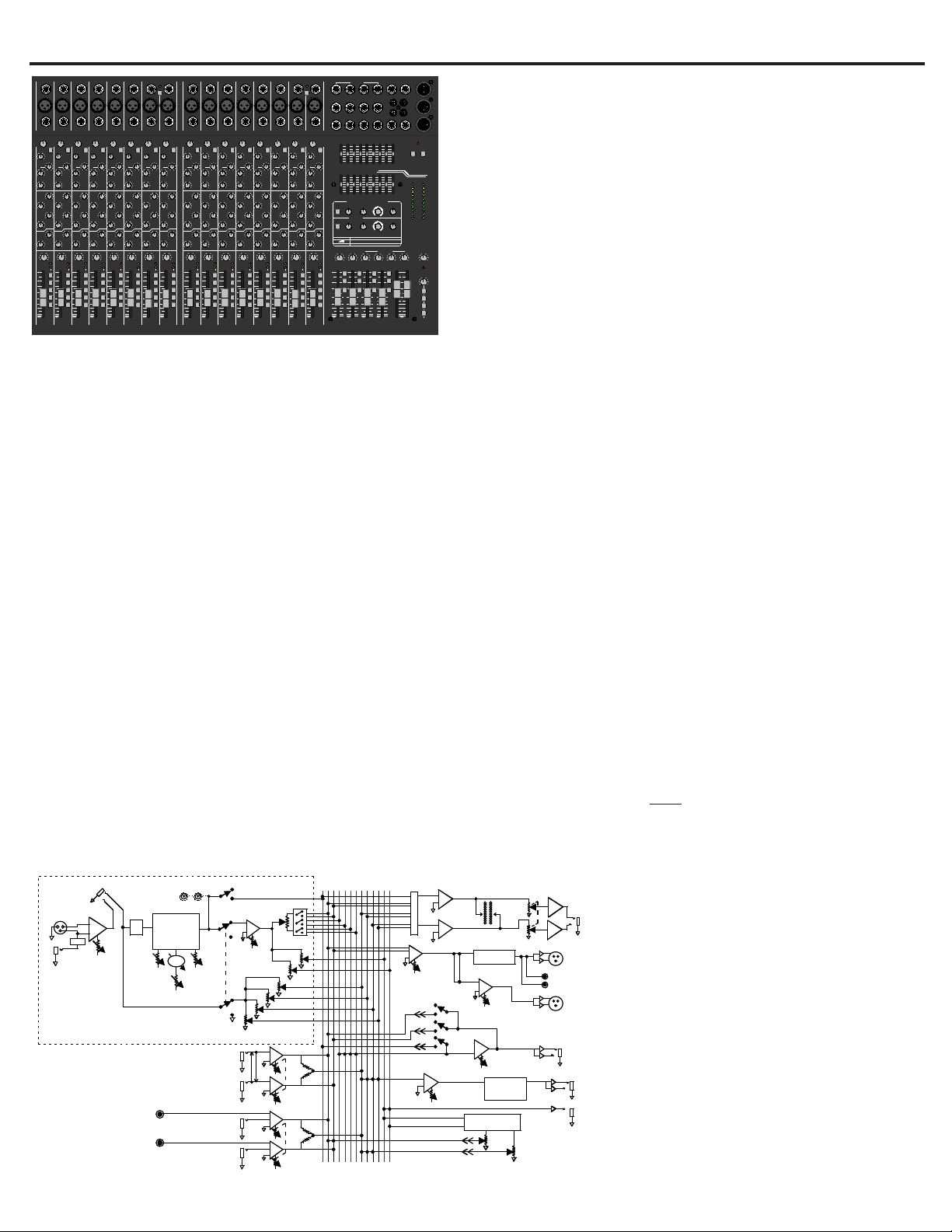
CARVIN ENGINEERING DATA C844, C1644(P), C2444, C3244 4-BUS MIXER OPERATING MANUAL
12340 World Trade Drive, San Diego, CA 92128
carvin.com (800) 854-2235
76-02444 0703
C1644 BLOCK DIAGRAM
MONO
0 0 0
0105010501050105010
5
RTN 3 MON 2MON 1 MON 4RTN 4 MON 3
TAPE INRETURN MONITORS
010
5
MONO
L-R
+18
+12
+6
0
-
6
-
12
-
18
-
24
-
30
PEAK
LR
POWER
PFL
PHONES
EQ 1
LEFT /
MON 1
EQ 2
RIGHT /
MON 2
dB
CONCERT SERIES
C1644
010
5
-
30
-
50
+
-
12
-
24
12
+
6
-
30
-
50
-
12
-
24
12
6
-
30
-
50
-
12
-
24
12
6
-
30
-
50
-
12
-
24
12
6
-
30
-
50
+
-
12
-
24
12
+
6
010
5
LEFT
RIGHT
LEFT
RIGHT
LEFT
RIGHT
LEFT
RIGHT
125 250 50063 1K 2K 4K 8K 16K
0
8
4
4
8
–12
+12
0
8
4
4
8
12-
12+
0
8
4
4
8
–12
+12
0
8
4
4
8
12-
12+
LR
TAPE IN
1
L
TAPE OUT
R
MON 1
423
PHONES
EFF 1 3L 3R
RETURN
MONO
MON 2 MON 3
RTN 4
MON 4
EFF SW
EFF 2
GROUPS
METERS
1234LR
PFL PFL PFL PFL
00
1-2
3-4
MON
MON
43218765
87654321
LINELINELINE LINELINELINELINE
86543217
1- 8
PHANTOM
POWER
MICMICMICMICMICMICMIC MIC
INSERT INSERT INSERT INSERT INSERT INSERT INSERT INSERT
121110916151413
161514131211109
9-16
PHANTOM
POWER
MIDMIDMIDMIDMIDMIDMIDMID
HIHIHIHIHIHIHIHI
FREQFREQ FREQFREQ FREQFREQ FREQFREQ
PFL
MUTE
3-4
1-2
L-R
0
-
12
-
24
-
30
-
50
+
12
+
6
-
6
100 5k
1k
010
5
010
5
010
5
010
5
010
5
010
5
C
LR
PANPA NPANPANPANPA NPANPAN
PEAK
SIG
PEAK
SIG
PEAK
SIG
PEAK
SIG
PEAK
SIG
PEAK
SIG
PEAK
SIG
PEAK
SIG
050
GAIN
LO CUT
LINE
PFL
MUTE
3-4
1-2
L-R
0
-
12
-
24
-
30
-
50
+
12
+
6
-
6
100 5k
1k
010
5
010
5
010
5
010
5
010
5
010
5
C
LR
050
GAIN
LO CUT
PFL
MUTE
3-4
1-2
L-R
0
-
12
-
24
-
30
-
50
+
12
+
6
-
6
100 5k
1k
010
5
010
5
010
5
010
5
010
5
010
5
C
LR
050
GAIN
LO CUT
PFL
MUTE
3-4
1-2
L-R
0
-
12
-
24
-
30
-
50
+
12
+
6
-
6
100 5k
1k
010
5
010
5
010
5
010
5
010
5
010
5
C
LR
050
GAIN
LO CUT
PFL
MUTE
3-4
1-2
L-R
0
-
12
-
24
-
30
-
50
+
12
+
6
-
6
100 5k
1k
010
5
010
5
010
5
010
5
010
5
010
5
C
LR
050
GAIN
LO CUT
PFL
MUTE
3-4
1-2
L-R
0
-
12
-
24
-
30
-
50
+
12
+
6
-
6
100 5k
1k
010
5
010
5
010
5
010
5
010
5
010
5
C
LR
050
GAIN
LO CUT
PFL
MUTE
3-4
1-2
L-R
0
-
12
-
24
-
30
-
50
+
12
+
6
-
6
100 5k
1k
010
5
010
5
010
5
010
5
010
5
010
5
C
LR
050
GAIN
LO CUT
LOW LOW LOW LOW LOW LOW LOW LOW
PFL
MUTE
3-4
1-2
L-R
0
-
12
-
24
-
30
-
50
+
12
+
6
-
6
100 5k
1k
010
5
010
5
010
5
010
5
010
5
010
5
C
LR
050
GAIN
LO CUT
0
-
15
+
15
0
-
15
+
15
0
-
15
+
15
0
-
15
+
15
0
-
15
+
15
0
-
15
+
15
0
-
15
+
15
0
-
15
+
15
0
-
15
+
15
0
-
15
+
15
0
-
15
+
15
0
-
15
+
15
0
-
15
+
15
0
-
15
+
15
0
-
15
+
15
0
-
15
+
15
0
-
15
+
15
LINELINELINE LINELINELINELINE
MICMICMICMICMICMICMIC MIC
INSERT INSERT INSERT INSERT INSERT INSERT INSERT INSERT
MIDMIDMIDMIDMIDMIDMIDMID
HIHIHIHIHIHIHIHI
FREQFREQ FREQFREQ FREQFREQ FREQFREQ
PFL
MUTE
3-4
1-2
L-R
0
-
12
-
24
-
30
-
50
+
12
+
6
-
6
100 5k
1k
010
5
010
5
010
5
010
5
010
5
010
5
C
LR
PANPA NPANPANPANPA NPANPAN
PEAK
SIG
PEAK
SIG
PEAK
SIG
PEAK
SIG
PEAK
SIG
PEAK
SIG
PEAK
SIG
PEAK
SIG
050
GAIN
LO CUT
LINE
PFL
MUTE
3-4
1-2
L-R
0
-
12
-
24
-
30
-
50
+
12
+
6
-
6
100 5k
1k
010
5
010
5
010
5
010
5
010
5
010
5
C
LR
050
GAIN
LO CUT
PFL
MUTE
3-4
1-2
L-R
0
-
12
-
24
-
30
-
50
+
12
+
6
-
6
100 5k
1k
010
5
010
5
010
5
010
5
010
5
010
5
C
LR
050
GAIN
LO CUT
PFL
MUTE
3-4
1-2
L-R
0
-
12
-
24
-
30
-
50
+
12
+
6
-
6
100 5k
1k
010
5
010
5
010
5
010
5
010
5
010
5
C
LR
050
GAIN
LO CUT
PFL
MUTE
3-4
1-2
L-R
0
-
12
-
24
-
30
-
50
+
12
+
6
-
6
100 5k
1k
010
5
010
5
010
5
010
5
010
5
010
5
C
LR
050
GAIN
LO CUT
PFL
MUTE
3-4
1-2
L-R
0
-
12
-
24
-
30
-
50
+
12
+
6
-
6
100 5k
1k
010
5
010
5
010
5
010
5
010
5
010
5
C
LR
050
GAIN
LO CUT
PFL
MUTE
3-4
1-2
L-R
0
-
12
-
24
-
30
-
50
+
12
+
6
-
6
100 5k
1k
010
5
010
5
010
5
010
5
010
5
010
5
C
LR
050
GAIN
LO CUT
LOW LOW LOW LOW LOW LOW LOW LOW
PFL
MUTE
3-4
1-2
L-R
0
-
12
-
24
-
30
-
50
+
12
+
6
-
6
100 5k
1k
010
5
010
5
010
5
010
5
010
5
010
5
C
LR
050
GAIN
LO CUT
0
-
15
+
15
0
-
15
+
15
0
-
15
+
15
0
-
15
+
15
0
-
15
+
15
0
-
15
+
15
0
-
15
+
15
0
-
15
+
15
0
-
15
+
15
0
-
15
+
15
0
-
15
+
15
0
-
15
+
15
0
-
15
+
15
0
-
15
+
15
0
-
15
+
15
0
-
15
+
15
0
-
15
+
15
0
-
15
+
15
0
-
15
+
15
0
-
15
+
15
0
-
15
+
15
0
-
15
+
15
0
-
15
+
15
0
-
15
+
15
PARAMETER
ECHO
REGEN
TIME
REVERB
DAMPING
DECAY
FLANGE
SPEED
DEPTH
CHORUS
REV LEVEL
DEPTH
SELECT
PK
PK
MUTE
MUTE
OFF
99
66
33
1MON 2MON
OFF
99
66
33
1MON 3MON
24-BIT DUAL STEREO EFFECTS
SELECT PARAMETER
101
2
3
4
56
7
8
9
101
2
3
4
5
6
7
8
9
EFFECTS 2
TO MONITORSRETURN
EFFECTS 1
100
1
2
3
4
5
6
7
8
9
100
1
2
3
4
5
6
7
8
9
161514131211109
4444 4444
3333 3333
2222 2222
1111 1111
MON MON MON MON MON MON MON MON
EFFEFFEFFEFF EFFEFFEFFEFF
1111 1111
2222 2222
4444 4444
3333 3333
2222 2222
1111 1111
MON MON MON MON MON MON MON MON
EFFEFFEFFEFF EFFEFFEFFEFF
1111 1111
2222 2222
c
E
C
H
O
R
E
V
E
R
B
C
H
O
R
U
S
F
L
A
N
G
E
E
C
H
O
R
E
V
E
R
B
C
H
O
R
U
S
F
L
A
N
G
E
C1644
CONCERT 44 SERIES The C844, C1644(P), C2444 and C3244 feature 8 to 32 channels with true 4-bus
performance. The C1644P adds four 300 watt power amplifiers built into our ROAD WARRIOR case. Never before
have so many features been packed into such a rugged, compact USA made mixer. The best feature of the Concert
44 Series is the sound. Sound that is pure and quiet enough for digital recording studios. Everything is logically laid out making the powerful features simple to use. The knobs have been located so that adjustments
can be made quick and easy with visible pointers showing you the status of your mix at a glance.
TRUE 4-BUS DESIGN The Concert 44 Series offers increased mixing flexibility over standard stereo consoles by letting you assign channels to one of the 4 sub groups or L/R. This allows you to mix the entire drum,
horn, choir, etc. into one sub group, which feeds the L/R faders. This is an easy way to control the volume of
grouped mics and inputs. If you don’t need subgrouping, you can depress the L/R channel button and the
channel goes directly into the L/R output like a standard stereo console. All 4 sub group outputs have balanced outputs for long cable runs.
TWO EFFECT SENDS / TWO 24-BIT EFFECT PROCESSORS Two built-in 24-Bit effects, each offering
256 stereo effects, is a first in a 4-bus mixing console. Since there are two, you no longer have to choose between
that great vocal reverb with delay and that awesome guitar chorus - you can have both! Each processor offers
lush REVERBS, rich CHORUSES, thick textured FLANGING and pristine ECHOES with fully adjustable parameters for damping, decay, depth, speed, time and regeneration. Both processors can be sent back into the monitor mix so the performers can hear exactly what the audience is hearing.
FOUR MONITOR SENDS Every channel has 4 MONITOR sends with MASTER output level controls. Monitor
send jacks are balanced TRS.
3 BAND EQ/MID SWEEP The superb EQ system gives extended 15 dB boost and cut tone shaping. The
LOW frequency control builds bass starting with 20 Hz through 80 Hz for a solid non-flabby low-end. The exclusive offset of the MID FREQ. control ends the confusion of selecting your mid frequency from 100 Hz to 5kHz.
The MID cut and boost control adjusts the gain to the perfect mid-dip or boost curve to enhance all instruments
and vocals. The 11.5k Hz HI treble control adds sparkle to your top-end without adding harshness. Both the
LOW and HI are “shelving”, which means they are effective from 20 Hz and up to 20k Hz. The LO CUT switch
eliminates stage rumble or other unwanted low frequencies that would normally rob power from your woofers.
TWO 9 BAND EQUALIZERS Precision equalizers provide precise 1 octave adjustments to tune in your overall sound and control feedback. Unlike one stereo equalizer, two independent 9 bands offers total flexibility.
With two convenient buttons, you can assign either EQ to the R/L outputs or to the 1/2 monitor outputs. Center
frequencies are 63, 125, 250, 500, 1k, 2k, 4k, 8k & 16k Hz.
RECEIVING INSPECTION—read before getting started
INSPECT YOUR MIXER FOR DAMAGE which may have occurred during shipping. If damage is
found, please notify the shipping company and CARVIN immediately.
SAVE THE CARTON & ALL PACKING MATERIALS. In the event you have to re-ship your unit, always
use the original carton and packing material. This will provide the best possible protection during
shipment. CARVIN and the shipping company are not liable for damage caused by improper packing.
SAVE YOUR INVOICE. It will be required for warranty service if needed in the future.
SHIPMENT SHORTAGE. If you find items missing, they may have been shipped separately. Please
allow several days for the rest of your order to arrive before inquiring.
RECORD THE SERIAL NUMBER on the enclosed warranty card or below on this manual for your
records. Keep your portion of the card and return the portion with your name and comments to us.
CHANNEL FEATURES Every channel has a full balanced XLR and LINE (1/4”) preamp with an INSERT
jack for a compressor or EQ that also serves as a DIRECT OUT when plugged half way. The PAN control directs the channel into the L/R output or any of the 4 sub groups after depressing the appropriate
ASSIGN switches. A PFL (pre fader listen) switch allows you to hear the channel before the fader is
turned up in the headphones. A solid “on” condition of the PEAK LED indicates that the MUTE switch
has been activated which turns the channel off including all monitor and effect sends. When flashing
during use, the PEAK LED also lets you know when to adjust the channel’s GAIN control to prevent channel cliping. The SIGNAL LED lets you know that a signal is coming through the channel starting at –20
dBu. A silky smooth 60mm audio taper FADER delivers professional fade-outs. The PHANTOM power
switches provide power through the XLR connectors for use with condenser mics like the Carvin CM90E
in groups of 8 channels.
MASTER FEATURES Each of the 4 SUB GROUP faders can be switched to the R/L outputs or used
independently through their own balanced output jacks. Each of the sub group’s PFL switches allow you
to listen to the sub groups in your headphones before it is turned up. The R/L MAIN output faders are
independent for added flexibility over a single stereo fader. A MONO control sums both the R/L outputs
together for a center, side fill or subwoofer output. The stereo HEADPHONE control tracks the METER
switches which allow you to look and listen from the L/R, MONO, MONITOR 1/2 and 3/4 outputs and
channel PFL switches. The master section also features 2 EFFECT SENDS, 4 RETURNS and RCA TAPE
IN/OUT jacks. All 4 SUB GROUPS, 4 MONITORS, XLR L/R and MONO outputs are balanced. A FOOT
SWITCH jack turns both effects processors on or off remotely with the optional FS22 foot switch.
SWITCHING POWER SUPPLY Our exclusive 125k Hz switching power supply eliminates transformer noise. Like a laptop computer, go anywhere in the world and not worry about power because
you can run on any voltage from 90 to 250VAC. (except C1644P)
SUPERB SOUND State-of-the-art low impedance, low noise preamps are featured on every channel.
The balanced common mode rejection is better than 70 dB to eliminate cable noise. All main outputs are
balanced to guard against system noise. The near theoretical limit on distortion has been achieved with THD
below .01% to guarantee the purity of your sound, ensuring it will be dynamically open and transparent.
ENGINEERED TO LAST Hidden deep in the heart of these San Diego, CA made mixers is the SMT construction that utilizes surface mounted components to prevent malfunctions caused by vibrations. Sealed
controls and switches guard against the outside elements while heavy-duty jacks provide a positive connection to your cables. Fire retardant FR-4 military spec circuit cards feature double-sided copper to eliminate radio frequency interference. Precision 1% tolerance components guarantee your settings will be
accurate every time. The Concert 44 Series is built to strict standards.
For your records, you may wish to record the following information. Serial No._________________________ InvoiceDate___________
Optional Accessories:
C844: CB800 Heavy padded bag FS22 foot switch for all models
C1644:
CB1600 Heavy padded bag AN1600 Anvil™ hard case
C2444: CB2400 Heavy padded bag AN2400 Anvil™ hard case
C3244: AN3200 Anvil™ hard case
c
CONCERT 44 SPECIFICATIONS:
For C1644P power amp specifcations see back page
Mic Input: Balanced XLR, Mic Imp. 150Ω
Line Input: Balanced 1/4” Jack Imp. 10k/20k bal.
Frequency Response: Mic or Line Inputs: 20Hz-20KHz ±0.5dB
Total Harmonic Distortion: Less than .01%
Equivalent Input Noise: 150 ohm source: -117dBu
Output Noise: less than -90dBu Master Line Out
Output Headroom: +28dB XLR bal, +20dB 1/4” unbal.
Maximum Gain: Mic in to Master Line Out: 74dB
Crosstalk: Adjacent channels: -60db at 1KHz
Common Mode Rejection: -75db at 1KHz
Phantom Power: All XLR Mic in (channel groups of 8)
Channel EQ.: 3 band active,LOW: 80Hz ±15dB
MID: 100Hz to 5kHz ±15dB
HI: 11.5KHz ±15dB
9 Band Graphic EQ.: ±12dB 63, 125, 250, 500, 1k, 2k, 4k, 16k
Mixers Only: 90 to 250VAC 50-60Hz, 20 to 50VA
Powered C1644P: 120VAC 60Hz or 240VAC 50Hz model,
1200VA
Size: C844: 14.25”D x 14.5”W x 3.25”H
C1644: 14.25”D x 22.25”W x 3.25”H
C1644P: 16”D x 24”W x 9”H
C2444: 14.25”D x 30”W x 3.25”H
C3244: 14.25”D x 38.1”W x 3.25”H
Page 2
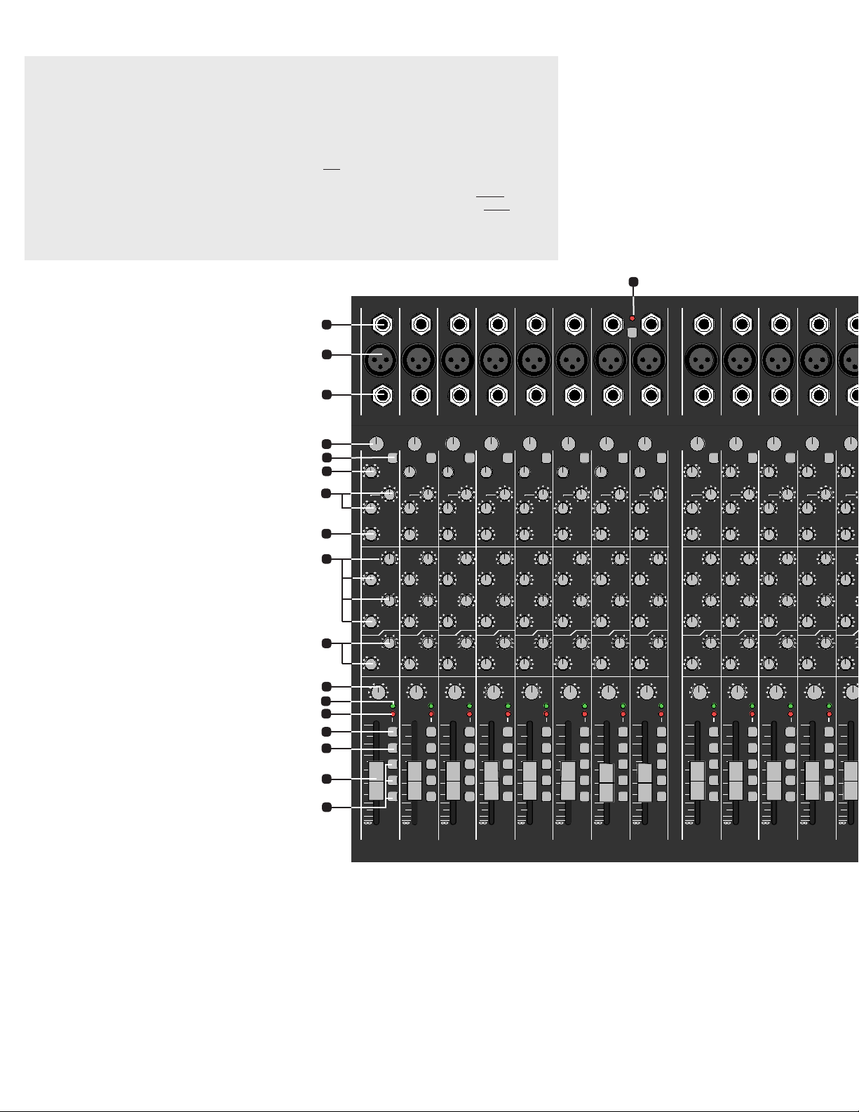
C44 SERIES CONTROLS
CHANNEL FEATURES
1. 1/4” LINE INPUTS
The line connectors are for connecting balanced and unbalanced instruments and line level sources such as drum
machines, keyboards, ETC.
2. XLR MIC INPUTS
The balanced Mic inputs are for connecting microphones that
use XLR connections. Both the LINE and XLR MIC inputs can
be used simultaneously.
3. CHANNEL INSERT/CHANNEL DIRECT OUT
To insert channel effects, compressor, etc. use a 1/4” TRS (Tip
Ring Sleeve) cable (see INSERTS AND DIRECT OUT illustration
on page 5 for TRS details). To achieve a direct out from the channel, insert a standard 1/4” cable to the first “click” (1/2 insert).
4. GAIN
The GAIN controls the input level for the channel. If the GAIN
is set too high, the PEAK LED will flash and distortion may
occur. Decrease the amount of GAIN until the PEAK LED does
not flash. It is important that the gain control should be kept
next to the PEAK LED flash point to maintain the lowest noise
of the channel. You can use the channel PFL switch to monitor the channel input level and use the meters to adjust the
GAIN control to 0dB. This will give you a good reference point
where the GAIN control should be set.
5. LOW CUT SWITCH
A 75 Hz LOW CUT filter helps eliminate unwanted low fre-
quencies. Great for reducing “boom” noise from mic stands
or from acoustic/electric guitars. Turning up the LOW EQ when
using this filter can help create a punchier bass response.
6. ACTIVE 3 BAND EQ WITH MID SWEEP
The C44 SERIES mixers provide studio EQ. The ±15 dB boost
or cut gives an overall 30 dB range for powerful EQ control.
The active circuits deliver deep bass from the 20-80 Hz LOW
control. The MID control works at 100Hz to 5kHz, depending on the MID FREQ control. The HI control functions at 1120k for crisp highs.
Start out with all tone controls at their center “zero” posi-
tion. Determine which position your MID FREQ sounds best,
then cut or boost your HI, MID, and LOW frequencies as
needed. If you are trying to mic instruments such as acoustic
guitar or drums, try various mics and mic placement before
adjusting your tone controls. A typical setting may be: HI +6,
MID -4 (MID FREQ set at 700Hz), and LOW +4. Don’t be afraid
to push the HI and LOW controls to get good presence and
depth while reducing the MIDs to clean up your sound. This
is one of the keys to great sound.
7. MID SWEEP
This control allows you to select which frequency (from 100Hz
to 5kHz) that the MID control will boost or cut. Instruments
and singers have various tonal qualities. By adjusting the MID
FREQ, you can select the exact frequency that will best complement these various inputs. 700Hz is a recommended setting for the MID FREQ control for guitar and vocals.
8. MONITOR 1 THRU 4 SEND CONTROLS
The channel MONITOR controls allow you to create four independent monitor mixes. The MONITOR signals (pre-EQ, pre
fader) are routed to the master MON 1, 2, 3 and 4 controls
(#21) respectively before going to the output connectors (#36).
9. EFF 1 & EFF 2 SEND CONTROLS
The EFF 1 or EFF 2 control sends signal (post EQ, post fader)
from the channel to the EFFECTS 1 or EFFECTS 2 internal
processors (#18) and to the EFF 1 or EFF 2 jacks (#33).
10. PAN CONTROL
Each channel’s PAN control allows stereo imaging by panning
Left or Right during recordings or live performances. The PAN
control also works for the sub-mix groups. A center position will send a channel’s signal to a pair of sub-group faders
(1-2, 3-4 when assigned). By panning hard left, the signal is
routed to only sub-group fader 1 or 3 when assigned. Panning
hard right routes the signal to sub-mix fader 2 or 4. Dual element pan controls provide 15dB greater separation than
standard pan controls.
11. CHANNEL SIGNAL GREEN LED
The SIGNAL LED is pre-fader and post EQ. This LED helps the
operator verify that the channel is receiving a signal from the
mic or instrument inputs even when the channel fader is off.
12. CHANNEL RED PEAK LED
This peak indicator is pre-fader and post EQ. If the PEAK LED
flashes, the channel needs a reduction with the GAIN control
(#4)to prevent distortion. A “solid” lit PEAK LED indicates that
the channel has been MUTED.
13. CHANNEL MUTE SWITCH
Use the MUTE switch to kill the channel. This feature saves
having to reset your faders and monitor sends.
14. CHANNEL PFL SWITCH
This switch allows the operator to listen to a channel (pre
fader listen) in the headphone mix to set tone and gain levels
as well as see the channel at the LED meter output (#29).
C844, C1644(P), C2444 & C3244 4-BUS MIXERS
QUICK START UP
If you’re like most new owners, you’re probably in a hurry
to plug your mixer in and use it. Here are some brief instructions to get you going quickly. With the mixer unplugged and
the unit turned off, complete the following procedures:
1. CONNECTING AC POWER TO YOUR MIXER
• The mixer can be used with 120 or 240VAC (it automatically switches internally except for C1644P)
• Use only a grounded (3 prong) power outlet to prevent a
shock hazard. This gives the quietest grounding for your mixer.
2. CONNECTING INPUTS TO YOUR MIXER
• For low level balanced devices such as microphones, plug
into the balanced MIC inputs using a shielded microphone
cable with XLR connectors.
• For high level balanced or unbalanced devices such as
instruments & keyboards, plug into the LINE input jacks using
a shielded cable with 1/4” phone plugs. Adjust the GAIN knob
for the mic or line input being used.
3. TURNING YOUR MIXER ON
• Adjust all channel FADERS and master LEVEL controls to
their OFF
positions
• Adjust all channel’s HI, MID, and BASS controls and the
two master 9 Band GRAPHICS to their center
positions.
• Adjust the Channel “PAN” controls to their center positions.
• Turn the mixer on by the rear panel POWER SWITCH
and watch for the POWER LED. Your mixer is now ready
to operate.
43218765
87654321
LINELINELINE LINELINELINELINE
86543217
1- 8
PHANTOM
POWER
MICMICMICMICMICMICMIC MIC
INSERT INSERT INSERT INSERT INSERT INSERT INSERT INSERT
1211109
131211109
MIDMIDMIDMIDMIDMIDMIDMID
HIHIHIHIHIHIHIHI
FREQFREQ FREQFREQ FREQFREQ FREQFREQ
PFL
MUTE
3-4
1-2
L-R
0
-
12
-
24
-
30
-
50
+
12
+
6
-
6
100 5k
1k
010
5
010
5
010
5
010
5
010
5
010
5
C
LR
PANPANPA NPANPANPA NPANPAN
PEAK
SIG
PEAK
SIG
PEAK
SIG
PEAK
SIG
PEAK
SIG
PEAK
SIG
PEAK
SIG
PEAK
SIG
050
GAIN
LO CUT
LINE
PFL
MUTE
3-4
1-2
L-R
0
-
12
-
24
-
30
-
50
+
12
+
6
-
6
100 5k
1k
010
5
010
5
010
5
010
5
010
5
010
5
C
LR
050
GAIN
LO CUT
PFL
MUTE
3-4
1-2
L-R
0
-
12
-
24
-
30
-
50
+
12
+
6
-
6
100 5k
1k
010
5
010
5
010
5
010
5
010
5
010
5
C
LR
050
GAIN
LO CUT
PFL
MUTE
3-4
1-2
L-R
0
-
12
-
24
-
30
-
50
+
12
+
6
-
6
100 5k
1k
010
5
010
5
010
5
010
5
010
5
010
5
C
LR
050
GAIN
LO CUT
PFL
MUTE
3-4
1-2
L-R
0
-
12
-
24
-
30
-
50
+
12
+
6
-
6
100 5k
1k
010
5
010
5
010
5
010
5
010
5
010
5
C
LR
050
GAIN
LO CUT
PFL
MUTE
3-4
1-2
L-R
0
-
12
-
24
-
30
-
50
+
12
+
6
-
6
100 5k
1k
010
5
010
5
010
5
010
5
010
5
010
5
C
LR
050
GAIN
LO CUT
PFL
MUTE
3-4
1-2
L-R
0
-
12
-
24
-
30
-
50
+
12
+
6
-
6
100 5k
1k
010
5
010
5
010
5
010
5
010
5
010
5
C
LR
050
GAIN
LO CUT
LOW LOW LOW LOW LOW LOW LOW LOW
PFL
MUTE
3-4
1-2
L-R
0
-
12
-
24
-
30
-
50
+
12
+
6
-
6
100 5k
1k
010
5
010
5
010
5
010
5
010
5
010
5
C
LR
050
GAIN
LO CUT
0
-
15
+
15
0
-
15
+
15
0
-
15
+
15
0
-
15
+
15
0
-
15
+
15
0
-
15
+
15
0
-
15
+
15
0
-
15
+
15
0
-
15
+
15
0
-
15
+
15
0
-
15
+
15
0
-
15
+
15
0
-
15
+
15
0
-
15
+
15
0
-
15
+
15
0
-
15
+
15
0
-
15
+
15
LINE LINELINELINELINE
MICMICMICMICMIC
INSERT INSERT INSERT INSERT INSERT
MMIDMIDMIDMID
HHIHIHIHI
FREQFREQ FREQFREQ FREQ
PFL
MUTE
3-4
1-2
L-R
0
-
12
-
24
-
30
-
50
+
12
+
6
-
6
100 5k
1k
010
5
010
5
010
5
010
5
010
5
010
5
C
LR
PANPANPA NPAN
PEAK
SIG
PEAK
SIG
PEAK
SIG
PEAK
SIG
PEA
S
050
GAIN
LO CUT
PFL
MUTE
3-4
1-2
L-R
0
-
12
-
24
-
30
-
50
+
12
+
6
-
6
100 5k
1k
010
5
010
5
010
5
010
5
010
5
010
5
C
LR
050
GAIN
LO CUT
PFL
MUTE
3-4
1-2
L-R
0
-
12
-
24
-
30
-
50
+
12
+
6
-
6
100 5k
1k
010
5
010
5
010
5
010
5
010
5
010
5
C
LR
050
GAIN
LO CUT
PFL
MUTE
3-4
1-2
L-R
0
-
12
-
24
-
30
-
50
+
12
+
6
-
6
100 5k
1k
010
5
010
5
010
5
010
5
010
5
010
5
C
LR
050
GAIN
LO CUT
0
-
12
-
24
-
30
-
50
+
12
+
6
-
6
1
010
5
010
5
010
5
C
LR
050
GAIN
LOW LOW LOW LOW L
0
-
15
+
15
0
-
15
+
15
0
-
15
+
15
0
-
15
+
15
0
-
15
+
15
0
-
15
+
15
0
-
15
+
15
0
-
15
+
15
0
-
15
+
15
0
-
15
+
15
0
-
15
+
15
0
-
15
+
15
0
-
15
+
15
0
-
15
+
15
0
-
15
+
15
131211109
4444 4444
3333 3333
2222 2222
1111 1111
MON MON MON MON MON MON MON MON
EFFEFFEFFEFF EFFEFFEFFEFF
1111 1111
2222 2222
44444
33333
22222
11111
MON MON MON MON MON
EFFEFFEFFEFF EFF
11111
22222
1
17
2
3
4
5
7
6
8
9
10
11
12
13
14
16
15
6
2
Page 3

15. CHANNEL ASSIGNMENT SWITCHES
These switches assign the channels’ signal to the Master L/R
faders, or to the SUB-GROUP faders 1 & 2, 3 & 4 for submixing in stereo pairs. For mono, PAN fully to the left and
assign a channel to Sub-Group fader 1 or 3 only. PAN fully
to the right and assign a channel to Sub-Group fader 2 or
4. Likewise assigning the L/R switches sends the channel
directly to the main L or R faders.
16. CHANNEL FADER
The CHANNEL FADER adjusts the output level of the channel.
The signal will go to one or more of the Master Faders, depending on both the Channel Assignment switches and the PAN control. Calibrated 109mm FADERS with audio tapers are featured
for smooth fade-outs. Slide all faders down when connecting your inputs.
17. MIC PHANTOM POWER SWITCH / RED LED
This switch provides +48V power for condenser mics such
as Carvin’s CM90E in groups of 8 channels. This leaves the
remaining MIC inputs for sources that don’t require phantom
power. The LINE inputs are unaffected by +48v power.
MASTER SECTION
18. TWO STEREO 24-BIT EFFECTS
The internal 24-BIT stereo processors receive signals from
the EFF 1 / EFF 2 channel controls. If the adjacent PK (peak)
LED flashes, reduce the level from the channel EFF 1 / EFF
2 send controls. A “solid” PK LED will show EFFECTS 1 or 2
have been muted either by the MUTE switches (#44) or by
the optional FS22 footswitch (#38). The RETURNcontrol will
adjust the volume level of the selected effects. Remember each
channel has its own two EFFECT sends that will send the signal
to the effects processors. The red PK LED will indicate when the
effects signal from the channel is distorting. Reduce the level
of the channel EFFECT control until the PK LED stops flashing.
EFFECT AND PARAMETERS
ECHO: When the SELECT control is at the “7 O-clock” posi-
tion, it is selected to the first ECHO setting where you get a single
repeat echo (minimal regeneration).
Turning the PARAMETER control to
1 will provide the shortest delay
time between the original signal and
the echo. Increasing the PARAME-
TER control to the right will increase
the time delay between the original
signal and the echo. To increase the
number of echo repeats, turn the
SELECT control clockwise to “9 Oclock” (maximum regeneration).
REVERB: When the SELECTcontrol
is at the “10 O-clock” position, it is
selected to the first REVERB setting.
Turning the SELECT control clockwise will increase the amount of high
frequencies in the reverb. Turning the
PARAMETER control to 1 will provide minimal decay time of the
reverb. Increasing to the right will
increase the reverb decay time.
CHORUS: When the SELECT control is at the “1 O-clock” position it
is selected to the first CHORUS set-
ting. Turning the SELECT control
clockwise will increase the amount
reverb in the chorus. Turning the
PARAMETER control to 1 will provide a minimal chorus depth setting.
Increasing to the right will increase
the chorus depth.
FLANGE: When the SELECTcontrol
is at the “4 O-clock” position it is
selected to the first FLANGE setting.
Turning the SELECT control clockwise will increase the flanger’s speed.
Turning the PARAMETER control to
1 will provide minimal flanging depth.
Increasing to the right will increase
the flanger’s depth.
To send effects to the monitors,
use the “TO MONITORS” controls,
MON 1/MON 2 & MON 1/MON 3.
The center position on both controls is OFF.
19. RETURN 3 L/R
Receives stereo or 2 mono effect signals from the RETURN 3
L /R jacks. These signals will also be present at MON 1 (#36).
20. RCA TAPE IN / RETURN 4
Receives a signal from the RTN 4 L/R 1/4” jacks (#35) & from the
TAPE IN jacks (#41). These signals will also be present at MON 1.
21. MONITOR 1-4 CONTROLS
These are the master outputs for the four monitor sends. These
correspond to the balanced 1/4” MON 1-4 output jacks
(#36)
.
22. GROUP/SUB-MIX FADERS 1-4
Once a channel has been assigned to one of these faders, the
mixing process is simplified to using these four faders. If
these faders are not assigned to the Master L-R faders (#25),
then each fader is bused to the corresponding 4 GROUP 1/4”
outputs (#37). By assigning the 4 faders to the Master L-R
faders, the operator can use the faders to sub-mix groups.
23. GROUP PFL SWITCHES
These
PFL
switches allow the operator to monitor the entire
GROUP mix. If
distortion is heard or if
the PFL level is near
PEAK
on the Master L/R METERS, lower the channel faders
assigned to that group. Also check the channel PEAK
LEDs.
24. GROUP ASSIGNMENT SWITCHES
These switches send the sub-group mix to the main L/R faders.
For mono mixing, assign to both L/R.
25. MASTER L/R FADERS
These faders adjust the level of the main stereo output created by
all channels and groups assigned to L/R faders. Output appears
at the L/R balanced XLR connectors
(#42)
.
26. MONO OUTPUT
The C44 SERIES creates an extra mono output from the
L/R
master faders (post) for center, side fill speakers or subwoofers.
The output is at the MONO XLR connector (#43).
27. HEADPHONE AND METER SOURCE
The stereo PHONES control sets the level of the PHONES jack
(#39). The PFL, L/R, MONO, MON 1-2 and MON 3-4 switches
allow for isolation of these sources through the headphones
and the L/R LED METERS (#29).
28. PFL RED LED
Indicates that the headphone & meters are monitoring only
the channels or groups where the PFL is switched on.
29. L/R LED VU METERS
This group of 10 LEDs offer 6 dB increment resolution that give
the operator a visual indication of the mixer’s output levels, selectable by the METER SOURCE or PFL switches
(#27).
30. DUAL PRECISION 9 BAND GRAPHIC EQs
are one octave filters at 60,125, 250, 500, 1k, 2k, 4k, 8k &
16k Hz centers that offer ±12dB adjustment to help eliminate feedback & enhance tone for the main or monitor mix.
31. EQ SWITCH 1 & 2
These switches swap the 9 band EQ’s from the standard L/R main
outputs “OUT” to the MON 1 & MON 2 outputs “IN” respectively.
32. POWER LED Verifies the mixer is on.
33. EFFECTS 1 & 2 OUTPUT JACKS
1/4” outputs drive external effects. Connect your effects
processor’s inputs to these jacks.
34. RETURN 3 L/R INPUT JACKS
Returns a stereo signal from an external effect. Connect your
effects processors’ stereo outputs to these jacks. If only one
RTN 3 jack is used, the mono signal will go to both L/R .
35. RTN 4 L/R INPUT JACKS
Returns a stereo signal from other sources.
36. MONITOR 1-4 OUTPUT JACKS
The C44 SERIES provides balanced 1/4” outputs for long cable
runs. Connect your monitor power amps to these jacks.
37. GROUP 1-4 OUTPUT JACKS
The C44 SERIES provides balanced 1/4” outputs. Connect your
4-track recorder or side fill power amps to these jacks.
38. EFF SW 1-2 FOOTSWITCH JACK
The optional FS22 will remotely shut off EFFECTS 1 or 2.
39. HEADPHONE JACK
1/4” stereo jack for headphone or control room output.
40. RCA L & R TAPE OUT
RCA jacks for connecting to a tape recorder input.
41. RCA L & R TAPE IN
For stereo playback of a tape/CD (parallel with RTN 4 jacks).
42. L/ R XLR OUTPUT CONNECTORS
This set of balanced XLR connectors are for connecting
the main L/R output to power amps or recording gear.
43. MONO XLR OUTPUT CONNECTOR
A balanced XLR output is featured for side fills or subwoofers.
MONO
0 0 0
0105010501050105010
5
RTN 3 MON 2MON 1 MON 4RTN 4 MON 3
TAPE INRETURN MONITORS
010
5
MONO
L-R
+18
+12
+6
0
-
6
-
12
-
18
-
24
-
30
PEAK
LR
POWER
PFL
PHONES
EQ 1
LEFT /
MON 1
EQ 2
RIGHT /
MON 2
dB
CONCERT SERIES
C1644
010
5
-
30
-
50
+
-
12
-
24
12
+
6
-
30
-
50
-
12
-
24
12
6
-
30
-
50
-
12
-
24
12
6
-
30
-
50
-
12
-
24
12
6
-
30
-
50
+
-
12
-
24
12
+
6
010
5
LEFT
RIGHT
LEFT
RIGHT
LEFT
RIGHT
LEFT
RIGHT
125 250 50063 1K 2K 4K 8K 16K
0
8
4
4
8
–12
+12
0
8
4
4
8
12-
12+
0
8
4
4
8
–12
+12
0
8
4
4
8
12-
12+
LR
TAPE IN
1
L
TAPE OUT
R
MON 1
423
PHONES
EFF 1 3L 3R
RETURN
MONO
MON 2 MON 3
RTN 4
MON 4
EFF SW
EFF 2
GROUPS
METERS
1234LR
PFL PFL PFL PFL
00
1-2
3-4
MON
MON
16151413
161514
9-16
PHANTOM
POWER
LINELINE
MICMIC MIC
INSERT INSERT INSERT
MIDMIDMIDMID
HIHIHIHI
FREQ FREQFREQ
PANPANPA NPAN
PEAK
SIG
PEAK
SIG
PEAK
SIG
LINE
PFL
MUTE
3-4
1-2
L-R
1k
010
5
010
5
010
5
LO CUT
PFL
MUTE
3-4
1-2
L-R
0
-
12
-
24
-
30
-
50
+
12
+
6
-
6
100 5k
1k
010
5
010
5
010
5
010
5
010
5
010
5
C
LR
050
GAIN
LO CUT
PFL
MUTE
3-4
1-2
L-R
0
-
12
-
24
-
30
-
50
+
12
+
6
-
6
100 5k
1k
010
5
010
5
010
5
010
5
010
5
010
5
C
LR
050
GAIN
LO CUT
PFL
MUTE
3-4
1-2
L-R
0
-
12
-
24
-
30
-
50
+
12
+
6
-
6
100 5k
1k
010
5
010
5
010
5
010
5
010
5
010
5
C
LR
050
GAIN
LO CUT
0
-
15
+
15
0
-
15
+
15
0
-
15
+
15
0
-
15
+
15
0
-
15
+
15
0
-
15
+
15
0
-
15
+
15
0
-
15
+
15
0
-
15
+
15
PARAMETER
ECHO
REGEN
TIME
REVERB
DAMPING
DECAY
FLANGE
SPEED
DEPTH
CHORUS
REV LEVEL
DEPTH
SELECT
PK
PK
MUTE
MUTE
OFF
99
66
33
1MON 2MON
OFF
99
66
33
1MON 3MON
24-BIT DUAL STEREO EFFECTS
SELECT PARAMETER
101
2
3
4
56
7
8
9
101
2
3
4
5
6
7
8
9
EFFECTS 2
TO MONITORSRETURN
EFFECTS 1
100
1
2
3
4
5
6
7
8
9
100
1
2
3
4
5
6
7
8
9
161514
4444
333
2222
111
MON MON MON
EFFEFFEFF
111
2222
c
E
C
H
O
R
E
V
E
R
B
C
H
O
R
U
S
F
L
A
N
G
E
E
C
H
O
R
E
V
E
R
B
C
H
O
R
U
S
F
L
A
N
G
E
36
37
18
29
30
31
32
33
34
35
43
42
21
26
28
23
27
19
22
23
25
20
40
38
39
41
3
44
Page 4

In a live sound reinforcement system, the input signals to the mixer will come from the microphones and instruments. Each microphone or instrument must be connected to one of the mixing
console inputs. It is preferred to have as many of the stage instruments as possible plugged into
the mixer. This allows for the best overall control of the instruments as they are mixed together
and then amplified by the system. The mixer can be operated on the stage or from a remote location in the audience using a “snake cable” to bring the signals from the stage to the mixer. The
advantage of the remote operation allows the performance to be mixed from the audience’s perspective. NOTE: Most snake cables are not designed for speaker connections.
THE SOUND CHECK
The sound check takes some skill but mostly patience from the performers and especially “you”
the system operator. If you get frustrated during the sound check, the sound may suffer due to
things missed in the sound check. The basic sound check follows this format: First test all microphones and other input devices(direct boxes, etc.) before the performers are included in the sound
check. A good thing to also check here is feedback in the monitors from the microphones. Good
positioning of the monitors and the use of a graphic equalizer solves most major monitor feedback problems. Now for a sound check with the performers. First set the level of each performer
individually and in cases where a performer has multiple microphones such as drummers, set
each drum mic individually then the drum set as a whole. This is also a good time to make some
channel EQ control adjustments to tailor the sound of the individual performers and instruments.
After setting each individual, have the performers run through a song. Don’t hesitate to stop the
performers if something needs to be adjusted or a performer or microphone needs to be heard
solo again. Remember the sound check is not a rehearsal but a system check. It is always a
good idea for the operator to have a microphone to inform the performers of what is needed during
the sound check. If a monitor system is being used, the operator’s microphone should only be
directed through the monitors when addressing the on stage performers, especially if something
needs to be checked during the show.
PROTECT
∞
5050
30
22
19
17
1515
13
12
11
10
9
8
7
6
5
4
3
2
1
0 dB0 dB
DCM1000
1000 Watt Power Amp
CLIP
SIGNAL
∞
5050
3030
22
19
17
1515
13
12
1111
10
9
8
7
6
5
4
3
2
1
0 dB0 dB
POWER
CHANNEL ONE CHANNEL TWO
CLIP
SIGNAL
PROTECT
∞
50
3030
2222
19
17
15
13
12
11
10
9
8
7
6
5
4
3
2
1
0 dB0 dB
DCM1000
1000 Watt Power Amp
CLIP
SIGNAL
∞
50
30
22
19
17
15
1313
1212
1111
10
9
8
7
6
5
4
3
2
1
0 dB0 dB
POWER
CHANNEL ONE CHANNEL TWO
CLIP
SIGNAL
PROTECT
∞
50
30
22
19
17
15
1313
12
11
10
9
8
7
6
5
4
3
2
1
0 dB
DCM1000
1000 Watt Power Amp
CLIP
SIGNAL
∞
5050
3030
22
19
17
15
13
12
11
10
9
8
7
6
5
4
3
2
1
0 dB0 dB
POWER
CHANNEL ONE CHANNEL TWO
CLIP
SIGNAL
PROTECT
∞
50
30
22
19
17
15
1313
12
11
10
9
8
7
6
5
4
3
2
1
0 dB
DCM1000
1000 Watt Power Amp
CLIP
SIGNAL
∞
5050
3030
22
19
17
15
13
12
11
10
9
8
7
6
5
4
3
2
1
0 dB0 dB
POWER
CHANNEL ONE CHANNEL TWO
CLIP
SIGNAL
PHANTOM
1-2
3-4
MONO
L-R
EQ 1 EQ 2
00
0105010501050105010
5
RTN 3 MON 2MON 1 MON 4RTN 4 MON 3
TAPE INRETURN MONITORS
010
5
PK
PK
MONO
MUTE
MUTE
MON4
EFF2
SOURCE
LR
POWER
PFL
PHONES
LEFT /
MON 1
RIGHT /
MON 2
+18
+12
+6
0
-
6
-12
-18
-24
-30
PEAK
dB
CONCERCONCERT SERIEST SERIES
C1644
010
5
OFF
99
66
33
1MON 2MON
OFF
99
66
33
1MON 3MON
-30
-50
-12
-24
12
6
-30
-50
-12
-24
12
6
-30
-50
-12
-24
12
6
-30
-50
+
-12
-24
12
010
5
LEFT
RIGHT
LEFT
RIGHT
LEFT
RIGHT
LEFT
RIGHT
24-BIT DUAL STEREO EFFECTS
125 250 50063 1K 2K 4K 8K 16K
0
8
4
4
8
±
12
+12
0
8
4
4
8
12-
12+
PARAM
ECHO
REGEN
TIME
REVERB
DAMPING
DECAY
FLANGE
SPEED
DEPTH
CHORUS
REV LEVEL
DEPTH
SELECT
SELECT PARAMETER
101
2
3
4567
8
9
101
2
3
4567
8
9
EFFECTS 2
TO MONITORSRETURN
EFFECTS 1
0
8
4
4
8
±12
+12
0
8
4
4
8
12-
12+
L R
TAPE IN
1
L
TAPE OUT
R
MON 1
423
PHONES
EFF 1 3L 3R
RETURN
MONO
MON 2 MON 3
RTN 4
MON 4
EFF 2
GROUPS
100
1
2
3
456
7
8
9
100
1
2
3
4
5
6
7
8
9
METERS
1234LR
PFL PFL PFL PFL
0 0
MON
MON
EFF SW 1 2
-
0
-12
-24
-30
-50
+
12
+
6
-6 -6-6 -6 -6
+
6
1-8
POWER
1
1
LINE
1
MIC
INSERT
MID
HI
C
LR
0
0
0
PAN
PEAK
SIG
010
5
010
5
2/3
MON
4
MON
EFF
1/2
1
MON
050
GAIN
LO
CUT
PFL
MUTE
3-4
1-2
L-R
OFF
MON
3MON 2
99
66
33
OFF
EFF
2EFF 1
99
66
33
LOW
FREQ
EFF
ALT
2
0
-12
-24
-30
-50
+
12
+
6
-6
100 5k
1k
+
15- 15
+
15- 15
+
15- 15
2
2
LINE
2
MIC
INSERT
MID
HI
C
LR
0
0
0
PAN
PEAK
SIG
010
5
010
5
2/3
MON
4
MON
EFF
1/2
1
MON
050
GAIN
LO
CUT
PFL
MUTE
3-4
1-2
L-R
OFF
MON
3MON 2
99
66
33
OFF
EFF
2EFF 1
99
66
33
LOW
FREQ
EFF
ALT
2
0
-12
-24
-30
-50
+
12
+
6
-6
100 5k
1k
+
15- 15
+
15- 15
+
15- 15
3
3
LINE
3
MIC
INSERT
MID
HI
C
LR
0
0
0
PAN
PEAK
SIG
010
5
010
5
2/3
MON
4
MON
EFF
1/2
1
MON
050
GAIN
LO
CUT
PFL
MUTE
3-4
1-2
L-R
OFF
MON
3MON 2
99
66
33
OFF
EFF
2EFF 1
99
66
33
LOW
FREQ
EFF
ALT
2
0
-12
-24
-30
-50
+
12
+
6
-6
100 5k
1k
+
15- 15
+
15- 15
+
15- 15
4
4
LINE
4
MIC
INSERT
MID
HI
C
LR
0
0
0
PAN
PEAK
SIG
010
5
010
5
2/3
MON
4
MON
EFF
1/2
1
MON
050
GAIN
LO
CUT
PFL
MUTE
3-4
1-2
L-R
OFF
MON
3MON 2
99
66
33
OFF
EFF
2EFF 1
99
66
33
LOW
FREQ
EFF
ALT
2
0
-12
-24
-30
-50
+
12
+
6
-6
100 5k
1k
+
15- 15
+
15- 15
+
15- 15
5
5
LINE
5
MIC
INSERT
MID
HI
C
LR
0
0
0
PAN
PEAK
SIG
010
5
010
5
2/3
MON
4
MON
EFF
1/2
1
MON
050
GAIN
LO
CUT
PFL
MUTE
3-4
1-2
L-R
OFF
MON
3MON 2
99
66
33
OFF
EFF
2EFF 1
99
66
33
LOW
FREQ
EFF
ALT
2
0
-12
-24
-30
-50
+
12
+
6
-6
100 5k
1k
+
15- 15
+
15- 15
+
15- 15
6
6
LINE
6
MIC
INSERT
MID
HI
C
LR
0
0
0
PAN
PEAK
SIG
010
5
010
5
2/3
MON
4
MON
EFF
1/2
1
MON
050
GAIN
LO
CUT
PFL
MUTE
3-4
1-2
L-R
OFF
MON
3MON 2
99
66
33
OFF
EFF
2EFF 1
99
66
33
LOW
FREQ
EFF
ALT
2
0
-12
-24
-30
-50
+
12
+
6
-6
100 5k
1k
+
15- 15
+
15- 15
+
15- 15
7
7
LINE
7
MIC
INSERT
MID
HI
C
LR
0
0
0
PAN
PEAK
SIG
010
5
010
5
2/3
MON
4
MON
EFF
1/2
1
MON
050
GAIN
LO
CUT
PFL
MUTE
3-4
1-2
L-R
OFF
MON
3MON 2
99
66
33
OFF
EFF
2EFF 1
99
66
33
LOW
FREQ
EFF
ALT
2
0
-12
-24
-30
-50
+
12
+
6
-6
100 5k
1k
+
15- 15
+
15- 15
+
15- 15
8
8
8
MIC
INSERT
MID
HI
C
LR
0
0
0
PAN
PEAK
SIG
010
5
010
5
2/3
MON
4
MON
EFF
1/2
1
MON
050
GAIN
LO
CUT
PFL
MUTE
3-4
1-2
L-R
OFF
MON
3MON 2
99
66
33
OFF
EFF
2EFF 1
99
66
33
LOW
FREQ
EFF
ALT
2
0
-12
-24
-30
-50
+
12
+
6
-6
100 5k
1k
+
15- 15
+
15- 15
+
15- 15
PHANTOM
9-16
POWER
9
9
LINE
9
MIC
INSERT
MID
HI
C
LR
0
0
0
PAN
PEAK
SIG
010
5
010
5
2/3
MON
4
MON
EFF
1/2
1
MON
050
GAIN
LO
CUT
PFL
MUTE
3-4
1-2
L-R
OFF
MON
3MON 2
99
66
33
OFF
EFF
2EFF 1
99
66
33
LOW
FREQ
EFF
ALT
2
0
-12
-24
-30
-50
+
12
+
6
-6
100 5k
1k
+
15- 15
+
15- 15
+
15- 15
10
10
LINE
10
MIC
INSERT
MID
HI
C
LR
0
0
0
PAN
PEAK
SIG
010
5
010
5
2/3
MON
4
MON
EFF
1/2
1
MON
050
GAIN
LO
CUT
PFL
MUTE
3-4
1-2
L-R
OFF
MON
3MON 2
99
66
33
OFF
EFF
2EFF 1
99
66
33
LOW
FREQ
EFF
ALT
2
0
-12
-24
-30
-50
+
12
+
6
-6
100 5k
1k
+
15- 15
+
15- 15
+
15- 15
11
11
LINE
11
MIC
INSERT
MID
HI
C
LR
0
0
0
PAN
PEAK
SIG
010
5
010
5
2/3
MON
4
MON
EFF
1/2
1
MON
050
GAIN
LO
CUT
PFL
MUTE
3-4
1-2
L-R
OFF
MON
3MON 2
99
66
33
OFF
EFF
2EFF 1
99
66
33
LOW
FREQ
EFF
ALT
2
0
-12
-24
-30
-50
+
12
+
6
-6
100 5k
1k
+
15- 15
+
15- 15
+
15- 15
12
12
LINE
12
MIC
INSERT
MID
HI
C
LR
0
0
0
PAN
PEAK
SIG
010
5
010
5
2/3
MON
4
MON
EFF
1/2
1
MON
050
GAIN
LO
CUT
PFL
MUTE
3-4
1-2
L-R
OFF
MON
3MON 2
99
66
33
OFF
EFF
2EFF 1
99
66
33
LOW
FREQ
EFF
ALT
2
0
-12
-24
-30
-50
+
12
+
6
-6
100 5k
1k
+
15- 15
+
15- 15
+
15- 15
13
13
LINE
13
MIC
INSERT
MID
HI
C
LR
0
0
0
PAN
PEAK
SIG
010
5
010
5
2/3
MON
4
MON
EFF
1/2
1
MON
050
GAIN
LO
CUT
PFL
MUTE
3-4
1-2
L-R
OFF
MON
3MON 2
99
66
33
OFF
EFF
2EFF 1
99
66
33
LOW
FREQ
EFF
ALT
2
0
-12
-24
-30
-50
+
12
+
6
-6
100 5k
1k
+
15- 15
+
15- 15
+
15- 15
14
14
LINE
14
MIC
INSERT
MID
HI
C
LR
0
0
0
PAN
PEAK
SIG
010
5
010
5
2/3
MON
4
MON
EFF
1/2
1
MON
050
GAIN
LO
CUT
PFL
MUTE
3-4
1-2
L-R
OFF
MON
3MON 2
99
66
33
OFF
EFF
2EFF 1
99
66
33
LOW
FREQ
EFF
ALT
2
0
-12
-24
-30
-50
+
12
+
6
-6
100 5k
1k
+
15- 15
+
15- 15
+
15- 15
15
15
LINE
15
MIC
INSERT
MID
HI
C
LR
0
0
0
PAN
PEAK
SIG
010
5
010
5
2/3
MON
4
MON
EFF
1/2
1
MON
050
GAIN
LO
CUT
PFL
MUTE
3-4
1-2
L-R
OFF
MON
3MON 2
99
66
33
OFF
EFF
2EFF 1
99
66
33
LOW
FREQ
EFF
ALT
2
0
-12
-24
-30
-50
+
12
+
6
-6
100 5k
1k
+
15- 15
+
15- 15
+
15- 15
16
16
16
MIC
INSERT
MID
HI
C
LR
0
0
0
PAN
PEAK
SIG
010
5
010
5
2/3
MON
4
MON
EFF
1/2
1
MON
050
GAIN
LO
CUT
PFL
MUTE
3-4
1-2
L-R
OFF
MON
3MON 2
99
66
33
OFF
EFF
2EFF 1
99
66
33
LOW
FREQ
EFF
ALT
2
0
-12
-24
-30
-50
+
12
+
6
-6
100 5k
1k
+
15- 15
+
15- 15
+
15- 15
E
C
H
O
R
E
V
E
R
B
C
H
O
R
U
S
F
L
A
N
G
E
R
E
C
H
O
R
E
V
E
R
B
C
H
O
R
U
S
F
L
A
N
G
E
R
10K
6K 45K
35K
25K
20
10 230
120
50
EQ IN
0
GAIN
PEAK
HI CUT
Hz
LOW CUT
Hz
-
OO
dB +6
31.5 4025 50 63
0dB
+6
+3
-3
-6
15
15
+
-
100 16012580 200 250 400 630500315
1k 1.25k800 1.6k 2k 3.15k 5k4k2.5k
6.3K 8K 12.5K 20K16K10K
10K
6K 45K
35K
25K
20
10 230
120
50
EQ IN
0
GAIN
PEAK
HI CUT
Hz
LOW CUT
Hz
-
OO
dB +6
31.5 4025 50 63
0dB
+6
+3
-3
-6
15
15
+
-
100 16012580 200 250 400 630500315
1k 1.25k800 1.6k 2k 3.15k 5k4k2.5k
6.3K 8K 12.5K 20K16K10K
ON
OFF
EQ2030
40 6325 100 160
0dB
+6
+3
-3
-6
15
15
+
-
400 1K630250 1.6K 2.5K 6.3K 16K10K4K
40 6325 100 160
0dB
+6
+3
-3
-6
15
15
+
-
400 1K630250 1.6K 2.5K 6.3K 16K10K4K
CHANNEL TWOCHANNEL ONE
ON
OFF
EQ2015
10K
6K 45K
35K
25K
20
10 230
120
50
EQ IN
0
GAIN
PEAK
HI CUT
Hz
LOW CUT
Hz
-
OO
dB +6
10K
6K 45K
35K
25K
20
10 230
120
50
EQ IN
0
GAIN
PEAK
HI CUT
Hz
LOW CUT
Hz
-
OO
dB +6
SOUND CHECK
CHANNEL CONNECTIONS AND SUB-MIXING
MASTER OUTPUTS
The main amps and speakers should contain an overall mix
of all channels. The sub-group faders 1-4 can have certain channels assigned to them before the mix arrives at the master LR faders. This is known as sub-mixing and can improve the
efficiency of mixing a large number of channels (see above).
The four independent monitor mixes should use the MON 1
through MON 4 sends. On the channel these sends are pre-EQ,
pre-fader. The MONO output can be used for a main mono
mix, a center mix or as a subwoofer output.
The sub group outputs can also be used as side or back fill
speakers. Long rooms can have poor sound at the back of the
room. Set up a set of back fill loudspeakers to fill in and add
a digital delay to the main speakers to correct the time delay
from front to back. This can improve the sound of the room
considerably.
PHANTOM
1-2
3-4
MONO
L-R
EQ 1 EQ 2
00
0105010501050105010
5
RTN 3 MON 2MON 1 MON 4RTN 4 MON 3
TAPE INRETURN MONITORS
010
5
PK
PK
MONO
MUTE
MUTE
MON4
EFF2
SOURCE
LR
POWER
PFL
PHONES
LEFT /
MON 1
RIGHT /
MON 2
+18
+12
+6
0
-
6
-12
-18
-24
-30
PEAK
dB
CONCERCONCERT SERIEST SERIES
C1644
010
5
OFF
99
66
33
1MON 2MON
OFF
99
66
33
1MON 3MON
-30
-50
-12
-24
12
6
-30
-50
-12
-24
12
6
-30
-50
-12
-24
12
6
-30
-50
+
-12
-24
12
010
5
LEFT
RIGHT
LEFT
RIGHT
LEFT
RIGHT
LEFT
RIGHT
24-BIT DUAL STEREO EFFECTS
125 250 50063 1K 2K 4K 8K 16K
0
8
4
4
8
±12
+12
0
8
4
4
8
12-
12+
PARAM
ECHO
REGEN
TIME
REVERB
DAMPING
DECAY
FLANGE
SPEED
DEPTH
CHORUS
REV LEVEL
DEPTH
SELECT
SELECT PARAMETER
101
2
3
4567
8
9
101
2
3
4567
8
9
EFFECTS 2
TO MONITORSRETURN
EFFECTS 1
0
8
4
4
8
±12
+12
0
8
4
4
8
12-
12+
L R
TAPE IN
1
L
TAPE OUT
R
MON 1
423
PHONES
EFF 1 3L 3R
RETURN
MONO
MON 2 MON 3
RTN 4
MON 4
EFF 2
GROUPS
100
1
2
3
456
7
8
9
100
1
2
3
4
5
6
7
8
9
METERS
1234LR
PFL PFL PFL PFL
0 0
MON
MON
EFF SW 1 2
-
0
-12
-24
-30
-50
+
12
+
6
-6 -6-6 -6 -6
+
6
1-8
POWER
1
1
LINE
1
MIC
INSERT
MID
HI
C
LR
0
0
0
PAN
PEAK
SIG
010
5
010
5
2/3
MON
4
MON
EFF
1/2
1
MON
050
GAIN
LO
CUT
PFL
MUTE
3-4
1-2
L-R
OFF
MON
3MON 2
99
66
33
OFF
EFF
2EFF 1
99
66
33
LOW
FREQ
EFF
ALT
2
0
-12
-24
-30
-50
+
12
+
6
-6
100 5k
1k
+
15- 15
+
15- 15
+
15- 15
2
2
LINE
2
MIC
INSERT
MID
HI
C
LR
0
0
0
PAN
PEAK
SIG
010
5
010
5
2/3
MON
4
MON
EFF
1/2
1
MON
050
GAIN
LO
CUT
PFL
MUTE
3-4
1-2
L-R
OFF
MON
3MON 2
99
66
33
OFF
EFF
2EFF 1
99
66
33
LOW
FREQ
EFF
ALT
2
0
-12
-24
-30
-50
+
12
+
6
-6
100 5k
1k
+
15- 15
+
15- 15
+
15- 15
3
3
LINE
3
MIC
INSERT
MID
HI
C
LR
0
0
0
PAN
PEAK
SIG
010
5
010
5
2/3
MON
4
MON
EFF
1/2
1
MON
050
GAIN
LO
CUT
PFL
MUTE
3-4
1-2
L-R
OFF
MON
3MON 2
99
66
33
OFF
EFF
2EFF 1
99
66
33
LOW
FREQ
EFF
ALT
2
0
-12
-24
-30
-50
+
12
+
6
-6
100 5k
1k
+
15- 15
+
15- 15
+
15- 15
4
4
LINE
4
MIC
INSERT
MID
HI
C
LR
0
0
0
PAN
PEAK
SIG
010
5
010
5
2/3
MON
4
MON
EFF
1/2
1
MON
050
GAIN
LO
CUT
PFL
MUTE
3-4
1-2
L-R
OFF
MON
3MON 2
99
66
33
OFF
EFF
2EFF 1
99
66
33
LOW
FREQ
EFF
ALT
2
0
-12
-24
-30
-50
+
12
+
6
-6
100 5k
1k
+
15- 15
+
15- 15
+
15- 15
5
5
LINE
5
MIC
INSERT
MID
HI
C
LR
0
0
0
PAN
PEAK
SIG
010
5
010
5
2/3
MON
4
MON
EFF
1/2
1
MON
050
GAIN
LO
CUT
PFL
MUTE
3-4
1-2
L-R
OFF
MON
3MON 2
99
66
33
OFF
EFF
2EFF 1
99
66
33
LOW
FREQ
EFF
ALT
2
0
-12
-24
-30
-50
+
12
+
6
-6
100 5k
1k
+
15- 15
+
15- 15
+
15- 15
6
6
LINE
6
MIC
INSERT
MID
HI
C
LR
0
0
0
PAN
PEAK
SIG
010
5
010
5
2/3
MON
4
MON
EFF
1/2
1
MON
050
GAIN
LO
CUT
PFL
MUTE
3-4
1-2
L-R
OFF
MON
3MON 2
99
66
33
OFF
EFF
2EFF 1
99
66
33
LOW
FREQ
EFF
ALT
2
0
-12
-24
-30
-50
+
12
+
6
-6
100 5k
1k
+
15- 15
+
15- 15
+
15- 15
7
7
LINE
7
MIC
INSERT
MID
HI
C
LR
0
0
0
PAN
PEAK
SIG
010
5
010
5
2/3
MON
4
MON
EFF
1/2
1
MON
050
GAIN
LO
CUT
PFL
MUTE
3-4
1-2
L-R
OFF
MON
3MON 2
99
66
33
OFF
EFF
2EFF 1
99
66
33
LOW
FREQ
EFF
ALT
2
0
-12
-24
-30
-50
+
12
+
6
-6
100 5k
1k
+
15- 15
+
15- 15
+
15- 15
8
8
8
MIC
INSERT
MID
HI
C
LR
0
0
0
PAN
PEAK
SIG
010
5
010
5
2/3
MON
4
MON
EFF
1/2
1
MON
050
GAIN
LO
CUT
PFL
MUTE
3-4
1-2
L-R
OFF
MON
3MON 2
99
66
33
OFF
EFF
2EFF 1
99
66
33
LOW
FREQ
EFF
ALT
2
0
-12
-24
-30
-50
+
12
+
6
-6
100 5k
1k
+
15- 15
+
15- 15
+
15- 15
PHANTOM
9-16
POWER
9
9
LINE
9
MIC
INSERT
MID
HI
C
LR
0
0
0
PAN
PEAK
SIG
010
5
010
5
2/3
MON
4
MON
EFF
1/2
1
MON
050
GAIN
LO
CUT
PFL
MUTE
3-4
1-2
L-R
OFF
MON
3MON 2
99
66
33
OFF
EFF
2EFF 1
99
66
33
LOW
FREQ
EFF
ALT
2
0
-12
-24
-30
-50
+
12
+
6
-6
100 5k
1k
+
15- 15
+
15- 15
+
15- 15
10
10
LINE
10
MIC
INSERT
MID
HI
C
LR
0
0
0
PAN
PEAK
SIG
010
5
010
5
2/3
MON
4
MON
EFF
1/2
1
MON
050
GAIN
LO
CUT
PFL
MUTE
3-4
1-2
L-R
OFF
MON
3MON 2
99
66
33
OFF
EFF
2EFF 1
99
66
33
LOW
FREQ
EFF
ALT
2
0
-12
-24
-30
-50
+
12
+
6
-6
100 5k
1k
+
15- 15
+
15- 15
+
15- 15
11
11
LINE
11
MIC
INSERT
MID
HI
C
LR
0
0
0
PAN
PEAK
SIG
010
5
010
5
2/3
MON
4
MON
EFF
1/2
1
MON
050
GAIN
LO
CUT
PFL
MUTE
3-4
1-2
L-R
OFF
MON
3MON 2
99
66
33
OFF
EFF
2EFF 1
99
66
33
LOW
FREQ
EFF
ALT
2
0
-12
-24
-30
-50
+
12
+
6
-6
100 5k
1k
+
15- 15
+
15- 15
+
15- 15
12
12
LINE
12
MIC
INSERT
MID
HI
C
LR
0
0
0
PAN
PEAK
SIG
010
5
010
5
2/3
MON
4
MON
EFF
1/2
1
MON
050
GAIN
LO
CUT
PFL
MUTE
3-4
1-2
L-R
OFF
MON
3MON 2
99
66
33
OFF
EFF
2EFF 1
99
66
33
LOW
FREQ
EFF
ALT
2
0
-12
-24
-30
-50
+
12
+
6
-6
100 5k
1k
+
15- 15
+
15- 15
+
15- 15
13
13
LINE
13
MIC
INSERT
MID
HI
C
LR
0
0
0
PAN
PEAK
SIG
010
5
010
5
2/3
MON
4
MON
EFF
1/2
1
MON
050
GAIN
LO
CUT
PFL
MUTE
3-4
1-2
L-R
OFF
MON
3MON 2
99
66
33
OFF
EFF
2EFF 1
99
66
33
LOW
FREQ
EFF
ALT
2
0
-12
-24
-30
-50
+
12
+
6
-6
100 5k
1k
+
15- 15
+
15- 15
+
15- 15
14
14
LINE
14
MIC
INSERT
MID
HI
C
LR
0
0
0
PAN
PEAK
SIG
010
5
010
5
2/3
MON
4
MON
EFF
1/2
1
MON
050
GAIN
LO
CUT
PFL
MUTE
3-4
1-2
L-R
OFF
MON
3MON 2
99
66
33
OFF
EFF
2EFF 1
99
66
33
LOW
FREQ
EFF
ALT
2
0
-12
-24
-30
-50
+
12
+
6
-6
100 5k
1k
+
15- 15
+
15- 15
+
15- 15
15
15
LINE
15
MIC
INSERT
MID
HI
C
LR
0
0
0
PAN
PEAK
SIG
010
5
010
5
2/3
MON
4
MON
EFF
1/2
1
MON
050
GAIN
LO
CUT
PFL
MUTE
3-4
1-2
L-R
OFF
MON
3MON 2
99
66
33
OFF
EFF
2EFF 1
99
66
33
LOW
FREQ
EFF
ALT
2
0
-12
-24
-30
-50
+
12
+
6
-6
100 5k
1k
+
15- 15
+
15- 15
+
15- 15
16
16
16
MIC
INSERT
MID
HI
C
LR
0
0
0
PAN
PEAK
SIG
010
5
010
5
2/3
MON
4
MON
EFF
1/2
1
MON
050
GAIN
LO
CUT
PFL
MUTE
3-4
1-2
L-R
OFF
MON
3MON 2
99
66
33
OFF
EFF
2EFF 1
99
66
33
LOW
FREQ
EFF
ALT
2
0
-12
-24
-30
-50
+
12
+
6
-6
100 5k
1k
+
15- 15
+
15- 15
+
15- 15
E
C
H
O
R
E
V
E
R
B
C
H
O
R
U
S
F
L
A
N
G
E
R
E
C
H
O
R
E
V
E
R
B
C
H
O
R
U
S
F
L
A
N
G
E
R
00
-30
-50
-12
-24
12
6
-30
-50
-12
-24
12
6
-30
-50
-12
-24
12
6
-30
-50
+
-12
-24
12
LEFT
RIGHT
LEFT
RIGHT
LEFT
RIGHT
LEFT
RIGHT
1234LR
PFL PFL PFL PFL
0 00
-12
-24
-30
-50
+
12
+
6
-6 -6-6 -6 -6
+
6
CONNECTING UP
The XLR Mic inputs are balanced low impedance inputs. +48V Phantom
power for condenser mics is available in channel groups of eight. This
enables the user to group all mics that require phantom power together,
leaving the rest of the channels available for dynamic microphones or line
inputs. The XLR Mic inputs and balanced 1/4” Line inputs on each channel can be used simultaneously, however the two signals will be controlled
by the channel GAIN control. Adjust the level of the instruments to balance the mix. For stereo instruments, such as keyboards or drum
machines, use two consecutive channels to connect the Left and Right
outputs from the instrument. Then use the PAN
controls on the two
channels to pan hard left
and right for a stereo
mix. If a pair of individual channels are not
available, one of the
stereo returns in the
master section can be
used.
Whenever possible, try to group all related instruments or mics near each
other on the mixer. For example: put all drum mics on channels 1 through
8, guitars, bass and keyboards on 9 through 16, and vocals on 17 through
24. This will make mixing, channel assigning and sub-mixing easier to
manage.
SUB-MIXING
The 4 bus section on the C44 mixers can be used for main outputs, surround outputs, side fills, outputs to a multi-track recorder, etc. but the most
common use is for sub mixing. Sub grouping is the process of assigning
multiple channels to a sub group fader in the master section. This is usually done to decrease the number of faders needed to adjust a group of
channels. For example: a drum kit with 6 or more microphones mixed in
mono can be assigned to a sub-mix fader. If the drums need to be adjusted
in the main mix, only one group fader needs to be adjusted instead of 6
channel faders. The individual microphones all use different fader settings, so it is important to get a balanced mix of the entire drum kit during
the sound check. The drum sub-group faders are then assigned to the LR main faders. For a mono mix, use the channel pan controls to pan the
audio “hard left” and the audio will only be assigned to sub- group fader
1 or 3. Panning “hard right” will bus the audio to sub-mix faders 2 or 4.
Always keep channel and sub group faders higher than the master L-R
faders. Using the L-R fader or sub group fader to boost the level of a week
channel signal can result in excess noise.
The diagram depicts a standard live sound system
1. Stereo EQ and power amp for the main speakers on the Left/Right outputs.
2. Stereo power amp and EQ for two monitor mixes on the MON 1 and MON 2 outputs.
3. Bridged power amp for a subwoofer on the MONO output.
4. Power amp for side fill or back of room fill on the Group outputs.
5. External effects processor in the EFF2 and EFF3 return loop.
1
2
3
4
5
The illustration shows channels 1-4 assigned to a sub-mix fader
4
Page 5

DIRECT OUT
Plug a 1/4” mono cable “half way” into
the Channel Insert Jack. The “half” insert
connection creates a send signal without
breaking the channels signal path. The
insert in this mode is no longer used as
an insert but becomes what is called an
DIRECT out.
FULL INSERT
The insert jack is a Tip Ring Sleeve (TRS)
1/4” phone jack, where the tip is the send,
the ring is the return and the sleeve is
ground. When used as an insert point or
in full INSERT mode, the channel is opened
up to allow an external piece of equipment
to be inserted into the channels signal
path. The signal coming from the microphone preamplifier will be forced to go
through the external equipment before it
can continue back through the channel, reentering before the channel EQ controls.
Most external equipment is not set up for
the TRS plug directly so an adapter cable
such as the Carvin AP1 or PP10is required.
Plug the 1/4” stereo TRS end into the
mixer insert all the way. The two mono 1/4”
TS jacks at the opposite end are the send
and return cables. If both an INSERT and
a DIRECT out is required, “Y” the SEND
cable.
MIC
INSERT
1
12
3
6
9129
6
3
- 0 +
GAIN
HI
MID
LOW
5
4
3
2
1
010
9
8
7
6
12
3
6
9
12
9
6
3
- 0 +
12
3
6
9
12
9
6
3
- 0 +
LINE
MIC Pre-Amp
PIN 2 (+)
PIN 3 (–)
GAIN
TO EFFECTS
STEREO PLUG
FULL INSERT
INSERT JACK
SEND RETURN
TIP: SEND
SLEEVE: GROUND
RING: RETURN
INSERTS AND DIRECT OUTS
MIC
INSERT
1
12
3
6
9129
6
3
- 0 +
GAIN
HI
MID
LOW
5
4
3
2
1
010
9
8
7
6
12
3
6
9
12
9
6
3
- 0 +
12
3
6
9
12
9
6
3
- 0 +
LINE
PIN 2 (+)
PIN 3 (–)
MONO PLUG
1/2 INSERT
MIC Pre-Amp
GAIN
INSERT JACK
TO RECORDER
TIP: SIGNAL
SLEEVE: GROUND
PHANTOM
1-2
3-4
MONO
L-R
EQ 1 EQ 2
00
0105010501050105010
5
RTN 3 MON 2MON 1 MON 4RTN 4 MON 3
TAPE INRETURN MONITORS
010
5
PK
PK
MONO
MUTE
MUTE
MON4
EFF2
SOURCE
LR
POWER
PFL
PHONES
LEFT /
MON 1
RIGHT /
MON 2
+18
+12
+6
0
-
6
-12
-18
-24
-30
PEAK
dB
CONCER
CONCER
T SERIES
T SERIES
C1644
C1644
010
5
OFF
99
66
33
1MON 2MON
OFF
99
66
33
1MON 3MON
-30
-50
-12
-24
12
6
-30
-50
-12
-24
12
6
-30
-50
-12
-24
12
6
-30
-50
+
-12
-24
12
010
5
LEFT
RIGHT
LEFT
RIGHT
LEFT
RIGHT
LEFT
RIGHT
24-BIT DUAL STEREO EFFECTS
125 250 50063 1K 2K 4K 8K 16K
0
8
4
4
8
±12
+12
0
8
4
4
8
12-
12+
PARAM
ECHO
REGEN
TIME
REVERB
DAMPING
DECAY
FLANGE
SPEED
DEPTH
CHORUS
REV LEVEL
DEPTH
SELECT
SELECT PARAMETER
101
2
3
4567
8
9
101
2
3
4567
8
9
EFFECTS 2
TO MONITORSRETURN
EFFECTS 1
0
8
4
4
8
±12
+12
0
8
4
4
8
12-
12+
L R
TAPE IN
1
L
TAPE OUT
R
MON 1
423
PHONES
EFF 1 3L 3R
RETURN
MONO
MON 2 MON 3
RTN 4
MON 4
EFF 2
GROUPS
100
1
2
3
456
7
8
9
100
1
2
3
4
5
6
7
8
9
METERS
1234LR
PFL PFL PFL PFL
0 0
MON
MON
EFF SW 1 2
-
0
-12
-24
-30
-50
+
12
+
6
-6 -6-6 -6 -6
+
6
1-8
POWER
1
1
LINE
1
MIC
INSERT
MID
HI
C
LR
0
0
0
PAN
PEAK
SIG
010
5
010
5
2/3
MON
4
MON
EFF
1/2
1
MON
050
GAIN
LO
CUT
PFL
MUTE
3-4
1-2
L-R
OFF
MON
3MON 2
99
66
33
OFF
EFF
2EFF 1
99
66
33
LOW
FREQ
EFF
ALT
2
0
-12
-24
-30
-50
+
12
+
6
-6
1005k
1k
+
15- 15
+
15- 15
+
15- 15
2
2
LINE
2
MIC
INSERT
MID
HI
C
LR
0
0
0
PAN
PEAK
SIG
010
5
010
5
2/3
MON
4
MON
EFF
1/2
1
MON
050
GAIN
LO
CUT
PFL
MUTE
3-4
1-2
L-R
OFF
MON
3MON 2
99
66
33
OFF
EFF
2EFF 1
99
66
33
LOW
FREQ
EFF
ALT
2
0
-12
-24
-30
-50
+
12
+
6
-6
1005k
1k
+
15- 15
+
15- 15
+
15- 15
3
3
LINE
3
MIC
INSERT
MID
HI
C
LR
0
0
0
PAN
PEAK
SIG
010
5
010
5
2/3
MON
4
MON
EFF
1/2
1
MON
050
GAIN
LO
CUT
PFL
MUTE
3-4
1-2
L-R
OFF
MON
3MON 2
99
66
33
OFF
EFF
2EFF 1
99
66
33
LOW
FREQ
EFF
ALT
2
0
-12
-24
-30
-50
+
12
+
6
-6
1005k
1k
+
15- 15
+
15- 15
+
15- 15
4
4
LINE
4
MIC
INSERT
MID
HI
C
LR
0
0
0
PAN
PEAK
SIG
010
5
010
5
2/3
MON
4
MON
EFF
1/2
1
MON
050
GAIN
LO
CUT
PFL
MUTE
3-4
1-2
L-R
OFF
MON
3MON 2
99
66
33
OFF
EFF
2EFF 1
99
66
33
LOW
FREQ
EFF
ALT
2
0
-12
-24
-30
-50
+
12
+
6
-6
1005k
1k
+
15- 15
+
15- 15
+
15- 15
5
5
LINE
5
MIC
INSERT
MID
HI
C
LR
0
0
0
PAN
PEAK
SIG
010
5
010
5
2/3
MON
4
MON
EFF
1/2
1
MON
050
GAIN
LO
CUT
PFL
MUTE
3-4
1-2
L-R
OFF
MON
3MON 2
99
66
33
OFF
EFF
2EFF 1
99
66
33
LOW
FREQ
EFF
ALT
2
0
-12
-24
-30
-50
+
12
+
6
-6
1005k
1k
+
15- 15
+
15- 15
+
15- 15
6
6
LINE
6
MIC
INSERT
MID
HI
C
LR
0
0
0
PAN
PEAK
SIG
010
5
010
5
2/3
MON
4
MON
EFF
1/2
1
MON
050
GAIN
LO
CUT
PFL
MUTE
3-4
1-2
L-R
OFF
MON
3MON 2
99
66
33
OFF
EFF
2EFF 1
99
66
33
LOW
FREQ
EFF
ALT
2
0
-12
-24
-30
-50
+
12
+
6
-6
1005k
1k
+
15- 15
+
15- 15
+
15- 15
7
7
LINE
7
MIC
INSERT
MID
HI
C
LR
0
0
0
PAN
PEAK
SIG
010
5
010
5
2/3
MON
4
MON
EFF
1/2
1
MON
050
GAIN
LO
CUT
PFL
MUTE
3-4
1-2
L-R
OFF
MON
3MON 2
99
66
33
OFF
EFF
2EFF 1
99
66
33
LOW
FREQ
EFF
ALT
2
0
-12
-24
-30
-50
+
12
+
6
-6
1005k
1k
+
15- 15
+
15- 15
+
15- 15
8
8
8
MIC
INSERT
MID
HI
C
LR
0
0
0
PAN
PEAK
SIG
010
5
010
5
2/3
MON
4
MON
EFF
1/2
1
MON
050
GAIN
LO
CUT
PFL
MUTE
3-4
1-2
L-R
OFF
MON
3MON 2
99
66
33
OFF
EFF
2EFF 1
99
66
33
LOW
FREQ
EFF
ALT
2
0
-12
-24
-30
-50
+
12
+
6
-6
1005k
1k
+
15- 15
+
15- 15
+
15- 15
PHANTOM
9-16
POWER
9
9
LINE
9
MIC
INSERT
MID
HI
C
LR
0
0
0
PAN
PEAK
SIG
010
5
010
5
2/3
MON
4
MON
EFF
1/2
1
MON
050
GAIN
LO
CUT
PFL
MUTE
3-4
1-2
L-R
OFF
MON
3MON 2
99
66
33
OFF
EFF
2EFF 1
99
66
33
LOW
FREQ
EFF
ALT
2
0
-12
-24
-30
-50
+
12
+
6
-6
1005k
1k
+
15- 15
+
15- 15
+
15- 15
10
10
LINE
10
MIC
INSERT
MID
HI
C
LR
0
0
0
PAN
PEAK
SIG
010
5
010
5
2/3
MON
4
MON
EFF
1/2
1
MON
050
GAIN
LO
CUT
PFL
MUTE
3-4
1-2
L-R
OFF
MON
3MON 2
99
66
33
OFF
EFF
2EFF 1
99
66
33
LOW
FREQ
EFF
ALT
2
0
-12
-24
-30
-50
+
12
+
6
-6
1005k
1k
+
15- 15
+
15- 15
+
15- 15
11
11
LINE
11
MIC
INSERT
MID
HI
C
LR
0
0
0
PAN
PEAK
SIG
010
5
010
5
2/3
MON
4
MON
EFF
1/2
1
MON
050
GAIN
LO
CUT
PFL
MUTE
3-4
1-2
L-R
OFF
MON
3MON 2
99
66
33
OFF
EFF
2EFF 1
99
66
33
LOW
FREQ
EFF
ALT
2
0
-12
-24
-30
-50
+
12
+
6
-6
1005k
1k
+
15- 15
+
15- 15
+
15- 15
12
12
LINE
12
MIC
INSERT
MID
HI
C
LR
0
0
0
PAN
PEAK
SIG
010
5
010
5
2/3
MON
4
MON
EFF
1/2
1
MON
050
GAIN
LO
CUT
PFL
MUTE
3-4
1-2
L-R
OFF
MON
3MON 2
99
66
33
OFF
EFF
2EFF 1
99
66
33
LOW
FREQ
EFF
ALT
2
0
-12
-24
-30
-50
+
12
+
6
-6
1005k
1k
+
15- 15
+
15- 15
+
15- 15
13
13
LINE
13
MIC
INSERT
MID
HI
C
LR
0
0
0
PAN
PEAK
SIG
010
5
010
5
2/3
MON
4
MON
EFF
1/2
1
MON
050
GAIN
LO
CUT
PFL
MUTE
3-4
1-2
L-R
OFF
MON
3MON 2
99
66
33
OFF
EFF
2EFF 1
99
66
33
LOW
FREQ
EFF
ALT
2
0
-12
-24
-30
-50
+
12
+
6
-6
1005k
1k
+
15- 15
+
15- 15
+
15- 15
14
14
LINE
14
MIC
INSERT
MID
HI
C
LR
0
0
0
PAN
PEAK
SIG
010
5
010
5
2/3
MON
4
MON
EFF
1/2
1
MON
050
GAIN
LO
CUT
PFL
MUTE
3-4
1-2
L-R
OFF
MON
3MON 2
99
66
33
OFF
EFF
2EFF 1
99
66
33
LOW
FREQ
EFF
ALT
2
0
-12
-24
-30
-50
+
12
+
6
-6
1005k
1k
+
15- 15
+
15- 15
+
15- 15
15
15
LINE
15
MIC
INSERT
MID
HI
C
LR
0
0
0
PAN
PEAK
SIG
010
5
010
5
2/3
MON
4
MON
EFF
1/2
1
MON
050
GAIN
LO
CUT
PFL
MUTE
3-4
1-2
L-R
OFF
MON
3MON 2
99
66
33
OFF
EFF
2EFF 1
99
66
33
LOW
FREQ
EFF
ALT
2
0
-12
-24
-30
-50
+
12
+
6
-6
1005k
1k
+
15- 15
+
15- 15
+
15- 15
16
16
16
MIC
INSERT
MID
HI
C
LR
0
0
0
PAN
PEAK
SIG
010
5
010
5
2/3
MON
4
MON
EFF
1/2
1
MON
050
GAIN
LO
CUT
PFL
MUTE
3-4
1-2
L-R
OFF
MON
3MON 2
99
66
33
OFF
EFF
2EFF 1
99
66
33
LOW
FREQ
EFF
ALT
2
0
-12
-24
-30
-50
+
12
+
6
-6
1005k
1k
+
15- 15
+
15- 15
+
15- 15
E
C
H
O
R
E
V
E
R
B
C
H
O
R
U
S
F
L
A
N
G
E
R
E
C
H
O
R
E
V
E
R
B
C
H
O
R
U
S
F
L
A
N
G
E
R
A multi-track recorder can be connected to the Channel Insert jacks (1/2 plugged).
This set up could be used with a live set up to record a live show.
PHANTOM
1-2
3-4
MONO
L-R
EQ 1 EQ 2
00
0105010501050105010
5
RTN 3 MON 2MON 1 MON 4RTN 4 MON 3
TAPE INRETURN MONITORS
010
5
PK
PK
MONO
MUTE
MUTE
MON4
EFF2
SOURCE
LR
POWER
PFL
PHONES
LEFT /
MON 1
RIGHT /
MON 2
+18
+12
+6
0
-
6
-12
-18
-24
-30
PEAK
dB
CONCERCONCERT SERIEST SERIES
C1644C1644
010
5
OFF
99
66
33
1MON 2MON
OFF
99
66
33
1MON 3MON
-30
-50
-12
-24
12
6
-30
-50
-12
-24
12
6
-30
-50
-12
-24
12
6
-30
-50
+
-12
-24
12
010
5
LEFT
RIGHT
LEFT
RIGHT
LEFT
RIGHT
LEFT
RIGHT
24-BIT DUAL STEREO EFFECTS
125 250 50063 1K 2K 4K 8K 16K
0
8
4
4
8
±
12
+12
0
8
4
4
8
12-
12+
PARAM
ECHO
REGEN
TIME
REVERB
DAMPING
DECAY
FLANGE
SPEED
DEPTH
CHORUS
REV LEVEL
DEPTH
SELECT
SELECT PARAMETER
101
2
3
4567
8
9
101
2
3
4567
8
9
EFFECTS 2
TO MONITORSRETURN
EFFECTS 1
0
8
4
4
8
±
12
+12
0
8
4
4
8
12-
12+
L R
TAPE IN
1
L
TAPE OUT
R
MON 1
423
PHONES
EFF 1 3L 3R
RETURN
MONO
MON 2 MON 3
RTN 4
MON 4
EFF 2
GROUPS
100
1
2
3
456
7
8
9
100
1
2
3
4
5
6
7
8
9
METERS
1234LR
PFL PFL PFL PFL
0 0
MON
MON
EFF SW 1 2
-
0
-12
-24
-30
-50
+
12
+
6
-6 -6-6 -6 -6
+
6
1-8
POWER
1
1
LINE
1
MIC
INSERT
MID
HI
C
LR
0
0
0
PAN
PEAK
SIG
010
5
010
5
2/3
MON
4
MON
EFF
1/2
1
MON
050
GAIN
LO
CUT
PFL
MUTE
3-4
1-2
L-R
OFF
MON
3MON 2
99
66
33
OFF
EFF
2EFF 1
99
66
33
LOW
FREQ
EFF
ALT
2
0
-12
-24
-30
-50
+
12
+
6
-6
100 5k
1k
+
15- 15
+
15- 15
+
15- 15
2
2
LINE
2
MIC
INSERT
MID
HI
C
LR
0
0
0
PAN
PEAK
SIG
010
5
010
5
2/3
MON
4
MON
EFF
1/2
1
MON
050
GAIN
LO
CUT
PFL
MUTE
3-4
1-2
L-R
OFF
MON
3MON 2
99
66
33
OFF
EFF
2EFF 1
99
66
33
LOW
FREQ
EFF
ALT
2
0
-12
-24
-30
-50
+
12
+
6
-6
100 5k
1k
+
15- 15
+
15- 15
+
15- 15
3
3
LINE
3
MIC
INSERT
MID
HI
C
LR
0
0
0
PAN
PEAK
SIG
010
5
010
5
2/3
MON
4
MON
EFF
1/2
1
MON
050
GAIN
LO
CUT
PFL
MUTE
3-4
1-2
L-R
OFF
MON
3MON 2
99
66
33
OFF
EFF
2EFF 1
99
66
33
LOW
FREQ
EFF
ALT
2
0
-12
-24
-30
-50
+
12
+
6
-6
100 5k
1k
+
15- 15
+
15- 15
+
15- 15
4
4
LINE
4
MIC
INSERT
MID
HI
C
LR
0
0
0
PAN
PEAK
SIG
010
5
010
5
2/3
MON
4
MON
EFF
1/2
1
MON
050
GAIN
LO
CUT
PFL
MUTE
3-4
1-2
L-R
OFF
MON
3MON 2
99
66
33
OFF
EFF
2EFF 1
99
66
33
LOW
FREQ
EFF
ALT
2
0
-12
-24
-30
-50
+
12
+
6
-6
100 5k
1k
+
15- 15
+
15- 15
+
15- 15
5
5
LINE
5
MIC
INSERT
MID
HI
C
LR
0
0
0
PAN
PEAK
SIG
010
5
010
5
2/3
MON
4
MON
EFF
1/2
1
MON
050
GAIN
LO
CUT
PFL
MUTE
3-4
1-2
L-R
OFF
MON
3MON 2
99
66
33
OFF
EFF
2EFF 1
99
66
33
LOW
FREQ
EFF
ALT
2
0
-12
-24
-30
-50
+
12
+
6
-6
100 5k
1k
+
15- 15
+
15- 15
+
15- 15
6
6
LINE
6
MIC
INSERT
MID
HI
C
LR
0
0
0
PAN
PEAK
SIG
010
5
010
5
2/3
MON
4
MON
EFF
1/2
1
MON
050
GAIN
LO
CUT
PFL
MUTE
3-4
1-2
L-R
OFF
MON
3MON 2
99
66
33
OFF
EFF
2EFF 1
99
66
33
LOW
FREQ
EFF
ALT
2
0
-12
-24
-30
-50
+
12
+
6
-6
100 5k
1k
+
15- 15
+
15- 15
+
15- 15
7
7
LINE
7
MIC
INSERT
MID
HI
C
LR
0
0
0
PAN
PEAK
SIG
010
5
010
5
2/3
MON
4
MON
EFF
1/2
1
MON
050
GAIN
LO
CUT
PFL
MUTE
3-4
1-2
L-R
OFF
MON
3MON 2
99
66
33
OFF
EFF
2EFF 1
99
66
33
LOW
FREQ
EFF
ALT
2
0
-12
-24
-30
-50
+
12
+
6
-6
100 5k
1k
+
15- 15
+
15- 15
+
15- 15
8
8
8
MIC
INSERT
MID
HI
C
LR
0
0
0
PAN
PEAK
SIG
010
5
010
5
2/3
MON
4
MON
EFF
1/2
1
MON
050
GAIN
LO
CUT
PFL
MUTE
3-4
1-2
L-R
OFF
MON
3MON 2
99
66
33
OFF
EFF
2EFF 1
99
66
33
LOW
FREQ
EFF
ALT
2
0
-12
-24
-30
-50
+
12
+
6
-6
100 5k
1k
+
15- 15
+
15- 15
+
15- 15
PHANTOM
9-16
POWER
9
9
LINE
9
MIC
INSERT
MID
HI
C
LR
0
0
0
PAN
PEAK
SIG
010
5
010
5
2/3
MON
4
MON
EFF
1/2
1
MON
050
GAIN
LO
CUT
PFL
MUTE
3-4
1-2
L-R
OFF
MON
3MON 2
99
66
33
OFF
EFF
2EFF 1
99
66
33
LOW
FREQ
EFF
ALT
2
0
-12
-24
-30
-50
+
12
+
6
-6
100 5k
1k
+
15- 15
+
15- 15
+
15- 15
10
10
LINE
10
MIC
INSERT
MID
HI
C
LR
0
0
0
PAN
PEAK
SIG
010
5
010
5
2/3
MON
4
MON
EFF
1/2
1
MON
050
GAIN
LO
CUT
PFL
MUTE
3-4
1-2
L-R
OFF
MON
3MON 2
99
66
33
OFF
EFF
2EFF 1
99
66
33
LOW
FREQ
EFF
ALT
2
0
-12
-24
-30
-50
+
12
+
6
-6
100 5k
1k
+
15- 15
+
15- 15
+
15- 15
11
11
LINE
11
MIC
INSERT
MID
HI
C
LR
0
0
0
PAN
PEAK
SIG
010
5
010
5
2/3
MON
4
MON
EFF
1/2
1
MON
050
GAIN
LO
CUT
PFL
MUTE
3-4
1-2
L-R
OFF
MON
3MON 2
99
66
33
OFF
EFF
2EFF 1
99
66
33
LOW
FREQ
EFF
ALT
2
0
-12
-24
-30
-50
+
12
+
6
-6
100 5k
1k
+
15- 15
+
15- 15
+
15- 15
12
12
LINE
12
MIC
INSERT
MID
HI
C
LR
0
0
0
PAN
PEAK
SIG
010
5
010
5
2/3
MON
4
MON
EFF
1/2
1
MON
050
GAIN
LO
CUT
PFL
MUTE
3-4
1-2
L-R
OFF
MON
3MON 2
99
66
33
OFF
EFF
2EFF 1
99
66
33
LOW
FREQ
EFF
ALT
2
0
-12
-24
-30
-50
+
12
+
6
-6
100 5k
1k
+
15- 15
+
15- 15
+
15- 15
13
13
LINE
13
MIC
INSERT
MID
HI
C
LR
0
0
0
PAN
PEAK
SIG
010
5
010
5
2/3
MON
4
MON
EFF
1/2
1
MON
050
GAIN
LO
CUT
PFL
MUTE
3-4
1-2
L-R
OFF
MON
3MON 2
99
66
33
OFF
EFF
2EFF 1
99
66
33
LOW
FREQ
EFF
ALT
2
0
-12
-24
-30
-50
+
12
+
6
-6
100 5k
1k
+
15- 15
+
15- 15
+
15- 15
14
14
LINE
14
MIC
INSERT
MID
HI
C
LR
0
0
0
PAN
PEAK
SIG
010
5
010
5
2/3
MON
4
MON
EFF
1/2
1
MON
050
GAIN
LO
CUT
PFL
MUTE
3-4
1-2
L-R
OFF
MON
3MON 2
99
66
33
OFF
EFF
2EFF 1
99
66
33
LOW
FREQ
EFF
ALT
2
0
-12
-24
-30
-50
+
12
+
6
-6
100 5k
1k
+
15- 15
+
15- 15
+
15- 15
15
15
LINE
15
MIC
INSERT
MID
HI
C
LR
0
0
0
PAN
PEAK
SIG
010
5
010
5
2/3
MON
4
MON
EFF
1/2
1
MON
050
GAIN
LO
CUT
PFL
MUTE
3-4
1-2
L-R
OFF
MON
3MON 2
99
66
33
OFF
EFF
2EFF 1
99
66
33
LOW
FREQ
EFF
ALT
2
0
-12
-24
-30
-50
+
12
+
6
-6
100 5k
1k
+
15- 15
+
15- 15
+
15- 15
16
16
16
MIC
INSERT
MID
HI
C
LR
0
0
0
PAN
PEAK
SIG
010
5
010
5
2/3
MON
4
MON
EFF
1/2
1
MON
050
GAIN
LO
CUT
PFL
MUTE
3-4
1-2
L-R
OFF
MON
3MON 2
99
66
33
OFF
EFF
2EFF 1
99
66
33
LOW
FREQ
EFF
ALT
2
0
-12
-24
-30
-50
+
12
+
6
-6
100 5k
1k
+
15- 15
+
15- 15
+
15- 15
E
C
H
O
R
E
V
E
R
B
C
H
O
R
U
S
F
L
A
N
G
E
R
E
C
H
O
R
E
V
E
R
B
C
H
O
R
U
S
F
L
A
N
G
E
R
MULTI-TRACK RECORDING
Follow this set up for mixing down to a two track recorder.
Connect the Multi-track recorders’ outputs to the line inputs
of the channels. Use the headphones or connect a professional power amplifier (Carvin’s DCM power amps) and high
quality studio monitors (Carvin’s SRS6.5) to your main L/R
outputs to monitor your mixdown sessions. Mixing is a practiced skill. A trained ear will know when to add EQ, effects,
compression, gate. Listen to your favorite CD through the
same headphones or monitoring system you plan to mix
through. Note each instrument’s level and position in the
stereo mix. Use this as a guide to help mix your project.
MULTI-TRACK MIXDOWN
5
ADJUSTING THE 9-BAND EQ
When the 9 band graphic EQ sliders are in their “center” position, they do not affect the
audio signal. When the EQ sliders are raised or lowered from this position, they boost
or cut respectively a narrow band of frequencies. To reduce feedback in the low frequency
range, try lowering one of the 63, 125 or 250 Hz sliders. High frequency feedback is reduced
by lowering one of the 2k or 4k Hz sliders. To help with feedback reduction, the main speaker
should always be placed in front of the microphones.
For tone enhancement, you may want to raise the 63, 125 (for deeper bass) and the 4, 8
and 16k (for crisper highs). At the same time you may want to reduce the mid frequency at
1k forming a “smile” curve as shown.
125 25063
GRAPHIC EQ
500 1K
0
8
4
4
8
12
12
+
-
4K 16K8K2K
0
8
4
4
8
12
12
+
-
Page 6

CAUTION
RISK OF ELECTRIC SHOCK
DO NOT OPEN
SAFETY INSTRUCTIONS (EUROPEAN)
The conductors in the AC power cord are colored in accordance with the following code.
GREEN & YELLOW—Earth BLUE—Neutral BROWN—Live
U.K. MAIN PLUG WARNING: Amolded main plug that has been cut off from the cord is unsafe. NEVER
UNDER ANY CIRCUMSTANCES SHOULD YOU INSERT A DAMAGED OR CUT MAIN PLUG INTO A POWER SOCKET.
IMPORTANT! FOR YOUR PROTECTION, PLEASE READ THE FOLLOWING:
WATER AND MOISTURE: Appliance should not be used near water (near a bathtub, washbowl, kitchen
sink, laundry tub, in a wet basement, or near a swimming pool, etc). Care should be taken so that
objects do not fall and liquids are not spilled into the enclosure through openings.
POWER SOURCES: The appliance should be connected to a power supply only of the type described
in the operating instructions or as marked on the appliance.
GROUNDING OR POLARIZATION: Precautions should be taken so that the grounding or polarization means of an appliance is not defeated.
POWER CORD PROTECTION: Power supply cords should be routed so that they are not likely to
be walked on or pinched by items placed upon or against them, paying particular attention to cords
at plugs, convenience receptacles, and the point where they exit from the appliance.
SERVICING: The user should not attempt to service the appliance beyond that described in the
operating instructions. All other servicing should be referred to qualified service personnel.
FUSING: If your unit is equipped with a fuse receptacle, replace only with the same type fuse. Refer
to replacement text on the unit for correct fuse type.
REFER SERVICING TO QUALIFIED SERVICE PERSONNEL!
This symbol is intended to alert the user
to the presence of uninsulated “dangerous
voltage” within the product’s enclosure that
may be of sufficient magnitude to consti-
tute a risk of electric shock to persons.
This symbol is intended to alert the
user to the presence of important
operating and maintenance (servicing) instructions in the literature
accompanying the appliance.
LIMITED WARRANTY
Your Carvin mixer is guaranteed against failure for 1 YEAR unless otherwise stated. Carvin will
service and supply all parts at no charge to the customer providing the unit is under warranty.
Shipping costs are the responsibility of the customer. CARVIN DOES NOT PAY FOR PARTS OR
SERVICING OTHER THAN OUR OWN. A COPY OF THE ORIGINAL INVOICE IS REQUIRED TO
VERIFY YOUR WARRANTY. Carvin assumes no responsibility for horn drivers or speakers damaged by this unit. This warranty does not cover, and no liability is assumed, for damage due to:
natural disasters, accidents, abuse, loss of parts, lack of reasonable care, incorrect use, or failure
to follow instructions. This warranty is in lieu of all other warranties, expressed or implied. No
representative or person is authorized to represent or assume for Carvin any liability in connection with the sale or servicing of Carvin products.
CARVIN SHALL NOT BE LIABLE FOR INCIDEN-
TAL OR CONSEQUENTIAL DAMAGES.
When RETURNING merchandise to the factory, you may call for a return authorization number.
Describe in writing each problem. If your unit is out of warranty, you will be charged the current FLAT RATE for parts and labor to bring your unit up to factory specifications.
MAINTAINING YOUR EQUIPMENT
Avoid spilling liquids or allowing any other foreign matter inside the unit. The panel of your
unit can be wiped from time to time with a dry or slightly damp cloth in order to remove
dust and bring back the new look.
As with all pro gear, avoid prolonged use in caustic
environments such as dust or salt air. When used in such an environment, be sure the
mixer is adequately protected by a cover.
1
4
3
C1644P REAR PANEL
2
C1644P POWER AMP SPECIFICATIONS:
RMS Continuous Power: 4Ω (20-20kHz, .1%THD) 300W/amp
8Ω (20-20kHz, .1%THD) 200W/amp
Frequency Response: ±0.5dB, 20Hz-20kHz
±1.5dB, 10Hz-40kHz
THD: (50% output) 0.03%
Output Noise: < -75dBu speaker out (all levels minimum)
Protection Circuits:
Soft Start, Short Circuit, No Load, SpeakerGuard , Thermal
Shut-Off, Protect and Clip Indicators, Distortion-free Peak
Limiters.
Maximum Gain: Mic in to Speaker Out: 74dB
Power Requirements: 120VAC 60Hz or optional 240VAC 50Hz model, 1200VA
Size: 24”W x 16”D x 9”H
Weight: 38 lbs.
C1644P REAR PANEL FEATURES:
1 & 2. SPEAKER OUTPUTS
The 1/4” JACK (1.), and TWIST-LOK JACK (2.) of each amp are wired in parallel.
The minimum load for each amp is 4 OHMS
. Chaining together more than one speaker on an output is
fine as long as the total impedance is not below 4 ohms. If the speaker load is lower than 4 ohms, the
amp may go into one of the PROTECT modes. (Two 8 ohm speakers in parallel = 4 ohms) 12 Gauge TWISTLOK speaker cables are an industry standard for high power applicattions (pin 1+ is POS, pin 1- is NEG,
pins 2+ and 2- are not used). The 1/4” jacks are used for lower power applications. Use only 16 gauge
(or heavier) speaker cables, NOT shielded instrument cables. Turn power off before connecting speaker
cables.
3. AMP ROUTING switch will select between two internally routed configurations:
OUT postion: AMP1-LEFT, AMP2-RIGHT, AMP3-MONITOR1, AMP4-MONITOR2
IN position: 1 amp each, for Monitors 1 thru 4.
Speaker output levels are adjusted from the Left/Right faders or Monitor 1-4 controls. The front panel
GRAPHIC EQs function with the amps, depending on the front panel EQ1 and EQ2 switch settings.
4. AMP PATCH INSERT jacks offer full flexibility for mixer to amp signal routing. These jacks are T-R-S
(Tip-Ring-Sleeve). Tip is the power amp input. Ring is the signal sent from the mixer determined by the
AMP ROUTING switch. The limiters are post insert. Patching a compressor or equalizer between the
mixer and the amp can be done by using a stereo insert cable (like Carvin’s AP1). Connect the RING
signal to the INPUT of the external device, and the TIP signal from the OUTPUT of the device. Plugging
in a standard 1/4” cable (mono) into the AMP PATCH INSERT jacks allows any external signal to be sent
to the internal power amps.
***DO NOT USE A BALANCED CABLE***
For example, you may want to patch the GROUP outputs (1-4) into the power amps.
-Plug one end of each cable into the GROUP jacks on the top panel of the mixer.
-Plug the other ends of the cables into the AMP PATCH INSERT jacks.
The GROUP 1-4 faders will now control what is heard at the SPEAKER OUTPUTS.
C1644P FRONT PANEL INDICATORS:
5. AMP CLIP LEDs - The red CLIP LEDs will flash when the particular amp has reached it’s maximum
output. Occasional flashing caused by bass frquencies is OK. Consistent flashing caused by higher frequencies may damage drivers due to excessive distortion. This will not damage the amp.
6. PROTECT LED - The yellow LED indicates the power amp system has gone into one of its protection
modes. There will be no output from the amps. If the amp output has been short circuited, or overloaded
by putting less than 4 ohms on the output the amp will go into protection. Check for shorted speaker
cables and speaker impedance, then reset the POWER switch (off-on). If the amp has overheated, lower
the volume and make sure the fan vents are not blocked. Wait for the fan to cool the amps. Normal operation will return in about 1-3 minutes.
C1644P 1200w Powered Mixer
6
5
C1644P FRONT PANEL
 Loading...