

Page 1
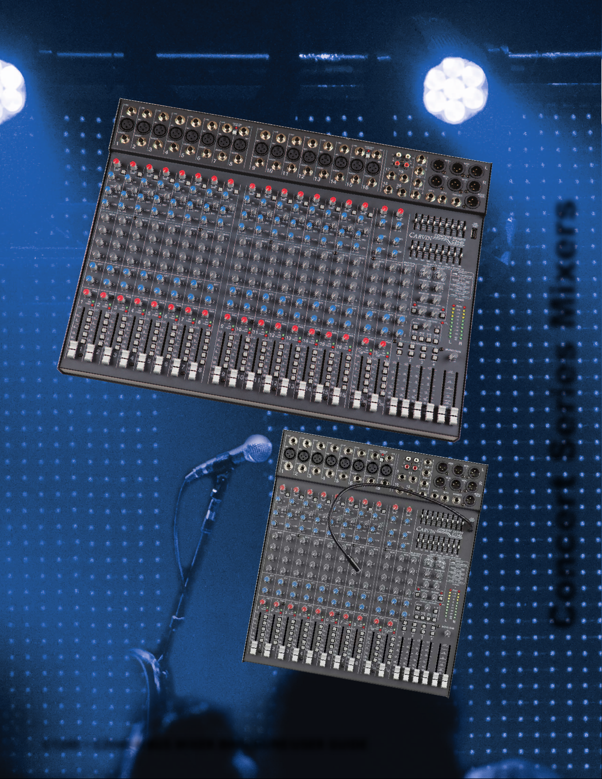
Concert Series Mixers
C1240 • C2040 4-BUS MIXER BROCHURE/USER GUIDE
c
Page 2
Overview
-6
+18
-0
+6
+12
20 20k50 100 200 500 1k 2k 5k
LO Mid
HI Mid
CARVIN has been serving the music
industry since 1946. Noted musicians
such as Frank Zappa, Steve Vai and Craig
Chaquico, have used Carvin consoles
over the years. Carvin’s commitment to
USA manufacturing 65 years ago is upheld
today in the face of most companies
turning to off-shore manufacturing. The
very best American workmanship and the
highest standards in quality control are
put into every Carvin product.
Improving Your Live Sound
Carvin’s C1240 and C2040 4-bus consoles
were designed for high performance live
mixing. Like all Carvin consoles, the heart
of each board starts with high quality Mic
Pre amps that provide smooth signals
with plenty of headroom. Construction and
circuit design is of the highest quality utilizing
sealed potentiometers; poly film capacitors
and 1% tolerance surface mount resistors.
With THD less than .01%, every sound will
remain pure to its source.
All primary outputs feature balanced
XLR connections. Main L-R, Subwoofer
and Monitor outputs are all balanced to
accommodate long runs from the board.
This is especially important when using
powered monitors. Sending a balanced
signal to the stage will ensure each monitor
amplifies a high quality mix.
Two 24-Bit on-board stereo effect
processors are available to every channel
through EFF send 1 and 2. Should an
outboard processor be needed, both EFF
sends can be routed out of the board
and returned in stereo using the last two
stereo channels.
Another alternate use of the EFF sends is
to use them as 2 additional monitor sends
should they be required. This would be
ideal for adding a personal ear monitor
system such as Carvin’s EM900. Should
the musicians choose to have both stage
monitors and ear monitors, the operator
can mix these separately and adjust master
levels separately as both the Monitor
sends and EFF sends have master send
controls.
Simplicity In Operation
These mixers are designed on a smallscale platform which will make it easy
to transport. No other console offers
more channels per linear desk inch. The
consoles are designed with the operator
in mind. Ease of operation is incredibly
important, because you may not have
a technician available. Everything is
logically arranged. Simply plug in the
channels, adjust the monitor levels and
bring up the main L/R faders and you’re
up and running.
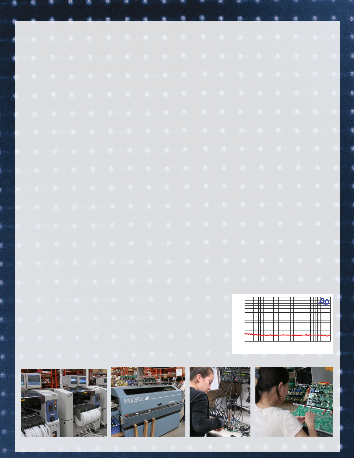
Stringent Testing
Our quality control department personally inspects every mixing console. After
the physical inspection, the most critical
and most important part of QC testing is
running every channel, master section and
connector through the Audio Precision™
computers to verify every function. This
means everything meets 100% of its
specifications. This is great assurance that
every EQ section, every output delivers the
highest voltages with the lowest possible
THD. The chart below shows that the THD
is actually .002% which is about 5 times
lower than our stated THD of .01%.
Construction
The engineering and design is what
you’d expect from this high-end
manufacturer. Ultra low-noise, high slew
rate IC’s for exceptional sound. Sealed
controls and switches guard against the
elements while the “SMT” Surface Mount
Technology construction ensures the
integrity of each component. The
rugged chassis incorporates the integral
SwitchMode™ 90V-260V 50-60 Hz power
supply, which can be used worldwide.
0.1
0.05
0.02
0.01
0.005
0.002
0.001
20
50
100 200 500 1k 2k
0dBu Mic input to Right out @ 0dBu
5k
20k
Carvin’s San Diego Factory
Page 3
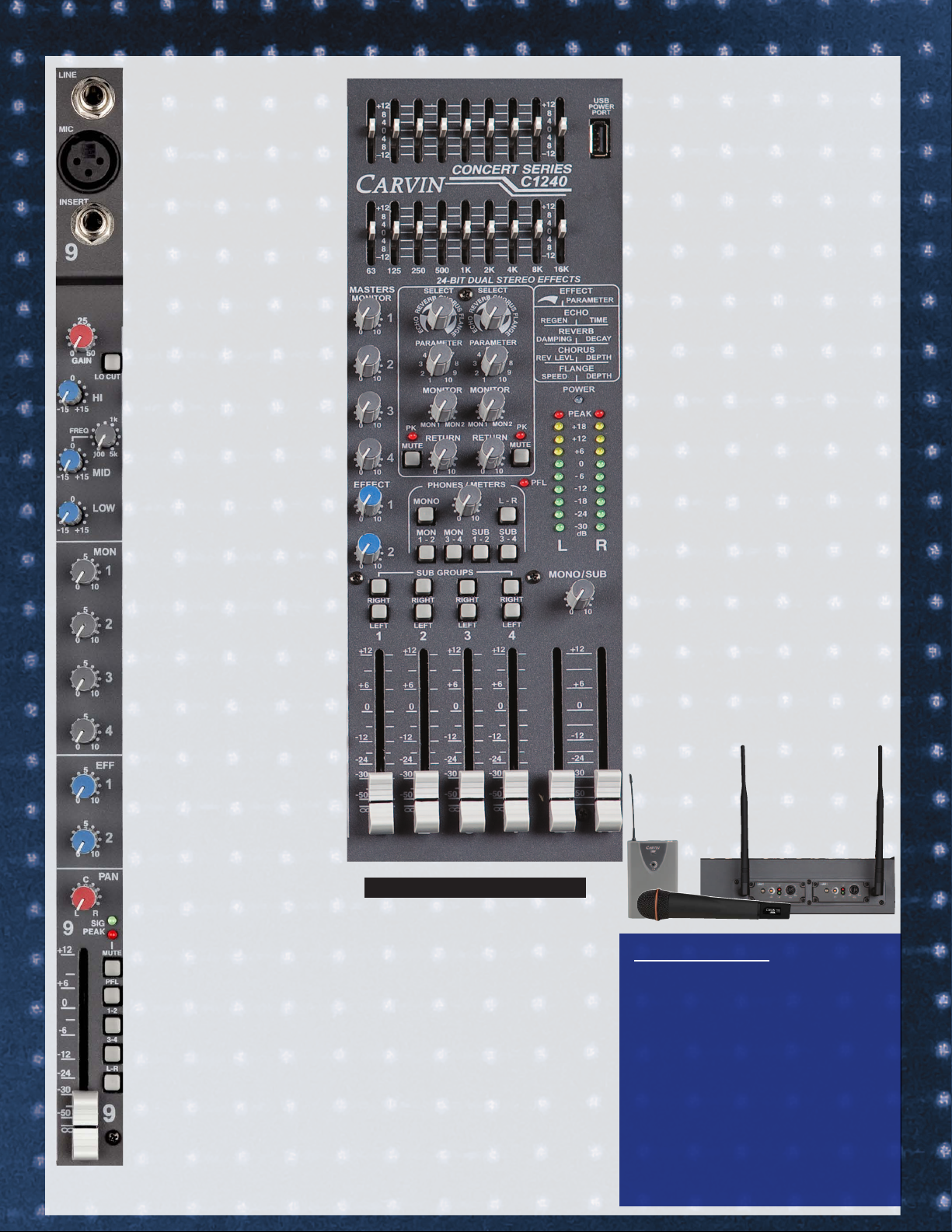
CHANNEL FEATURES
• 12 and 20 ch models
• 8 XLR + 4 Stereo CH or
16 XLR + 4 Stereo CH
• 4 Buses + L/R + MONO
• Adjustable Gain attenuator
• 3 Band EQ w/ Mid sweep
• Low Cut Filter
• 4 Ch Monitor Sends
• 2 Ch Effects Sends
• Ch mute/Peak indicator
• PFL/solo
3 BAND CH EQ + LO CUT
The 3-band Ch equalizer offers
both HF and LF EQ plus a mid
sweep to dial in critical midfrequencies. The LO CUT switch
eliminates frequencies below
75Hz. This is ideal for reducing
stage rumble and works well on
channels such as guitar and snare
drum where frequencies below
75Hz are not common.
4 CH MONITOR SENDS
4 monitor sends per channel is
ideal for providing each band
member their own custom monitor mix. Send each member’s
mix to a powered monitor or to
an in-ear monitor transmitter.
MASTER FEATURES
• 4 Sub Groups + L/R
• Center/Sub output
• 2 effect processors – 256 effects each
• Effects to monitors
• 2 9-band L/R Graphic EQ’s
• USB power port
• C2040: Rear slots for wireless options
(up to 2 mics or beltpacks)
• Ultra low THD – less than .001%
•
SwitchMode™ 90-260 VAC power supply
HEADPHONE MONITORING
Assign any combination of the 4 ch monitors, 4 busses, L/R and MONO outputs and
for headphone monitoring.
USB POWER PORT
A convenient USB power port is availalbe for
powering your iPod™ while in use or to power
an optional LED gooseneck light.
WIRELESS OPTION FOR C2040
The exclusive True Diversity USM16 built-in
wireless system can be installed in the C2040.
Two recievers can be installed which can be
used with wireless microphones, lavalier
mics or guitar transmitter. The signals are automatically routed to the first two channels on
the console. Each system is connected with a
simple plug-in connector. For more information, read about the UX16 wireless products,
which is the outboard version of the USM16.
See Carvin.com/USM.
2 CH EFFECT SENDS
2 effects sends permit two simulations effects for each channel
utilizing the two on board effects
processor or external processors.
CH FADERS &
ASSIGN SWITCHES
Each channel has assign switches that
allow the operator to bus each channel to the desired output. A mute and
PFL switch for solo monitoring is also
available on every channel.
See Demo CARVINCHANNEL.COM
SPECIFICATIONS
Freq. response: 20-20k Hz ±1 dB
THD distortion: .01% 20-20k Hz
E I N:
-117 dBm
S/N Ratio 90 dB
Dynamic Range: 104 dB
Mic Gain: 52 dB
Line Gain: 30 dB
Total Gain: 72 dB (balanced)
Max Output: +28 dBm
Power Req.
90 to 250VAC 50-60Hz
C1240: 14.5”W x 16.3D x 3.75”H, 14 lbs
36.8cmW x 41cmD x 9.5cmH, 6.4 kgs
C2040: 22.2”W x 16.3D x 3.75”H, 18 lbs
56cmW x 41.4cmD x 9.5cmH, 8.2 kgs
Page 4

QUICK START UP
Here are some brief instructions to get you going quickly.
With the mixer unplugged and the unit turned off, complete the following procedures:
1. CONNECTING AC POWER TO YOUR MIXER
• The mixer can be used with either 120 or 240VAC.
• Use only a grounded (3 prong) power outlet to prevent
a shock hazard and for the quietest grounding for your mixer.
2. CONNECTING INPUTS TO YOUR MIXER
• For low level balanced devices such as microphones,
plug into the balanced XLR MIC inputs.
• For high level balanced or unbalanced devices such
as instruments & keyboards, plug into the LINE input
jacks using a shielded 1/4” cable.
CHANNEL FEATURES
1. 1/4” LINE INPUTS
The line connectors are for connecting balanced and
unbalanced instruments and line level sources such as
drum machines, keyboards, ETC.
2. XLR MIC INPUTS
The balanced Mic inputs are for connecting microphones
with XLR connections. Both the LINE and XLR MIC inputs
can be used simultaneously.
3. CHANNEL INSERT/DIRECT OUT
To insert channel effects, compressor, etc. use a 1/4” TRS
(Tip/Ring/Sleeve) cable. For a direct out from the channel,
insert a standard 1/4” cable to the first “click” (half insert).
4. GAIN
The GAIN controls the input level for the channel. The
green SIG LED indicates the incoming signal. The PEAK
LED will flash red if the GAIN is set too high. Turn down
the GAIN until the PEAK LED does not flash to avoid distortion. You can use the channel PFL switch to monitor
the channel input level and use the meters to adjust the
GAIN control to 0dB for optimal signal gain.
5. LOW CUT SWITCH
A 75 Hz LOW CUT filter helps eliminate unwanted low
frequencies. Great for reducing “boom” noise from mic
stands or from acoustic/electric guitars. Turning up the
LOW EQ when using this filter can help create a punchier
bass response.
6. 3 BAND ACTIVE EQ
The ±15 dB boost or cut gives an overall 30 dB range for
powerful EQ control. The active circuits deliver deep bass
from the 20-80 Hz LOW control. The MID control works
from 100 to 5kHz, depending on the MID FREQ setting.
The stereo channels feature a ±15 dB MID boost or cut.
The HI control functions from 11-20k.
Start out with all tone controls at their center “zero” position. Determine which position your MID FREQ sounds
best, then cut or boost your HI and LOW frequencies as
needed. Try various mics and mic placement on instruments before adjusting the EQ. A typical setting may be:
HI -3, MID FREQ set at 700Hz -3 and LOW +3.
7. MID SWEEP
These controls allow you to select which frequency that the
MID control boost or cut. By adjusting the MID FREQ, you can
select the exact frequency to boost or cut that will best
complement various inputs. 700Hz is recommended for
the MID FREQ control for guitar & vocals.
Don’t be afraid to adjust the HI, MID & LOW controls to
get good presence and depth. This is one of the keys to
great sound.
8. MONITOR 1 THRU 4 SEND CONTROLS
The channel MONITORS allow you to create four independent monitor mixes. The MONITOR signals (pre-EQ,
pre fader) are routed to the master MON 1, 2, 3, & 4
controls (#20) respectively before going to the XLR output
connectors (#33).
3. TURNING YOUR MIXER ON
• Adjust all channel FADERS and master LEVEL controls
to their OFF positions
• Adjust all channel’s HI , M ID , a nd BA SS
controls and the two master 9 Band GRAPHICS to
their center positions.
• Adjust the Channel “PAN” controls to their center
positions.
• Turn the mixer on by the rear panel POWER SWITCH
and watch for the POWER LED.
• Adjust the GAIN controls for the channels being used.
Your mixer is now ready to operate.
9. EFF 1 & EFF 2 SEND CONTROLS
The EFF 1 or EFF 2 control sends signal (post EQ, post
fader) from the channel to the master EFFECTS 1 or
EFFECTS 2 levels to the internal processors (#19) and
to the EFF 1 or EFF 2 external output (#32).
10. PAN CONTROL
Each channel’s PAN control allows stereo imaging by
panning Left or Right during recordings or live performances. The PAN control also works for the sub-mix
groups. A center position will send a channel’s signal to
a pair of sub-group faders (1-2, 3-4 when assigned). By
panning hard left, the signal is routed to only sub-group
fader 1 or 3 when assigned. Panning hard right routes
the signal to sub-mix fader 2 or 4. Dual element pan
controls provide 15dB greater channel separation than
standard pan controls
11. CHANNEL SIGNAL GREEN LED
The SIGNAL LED is pre-fader and post EQ. This LED
helps the operator verify that the channel is receiving a
signal from the mic or instrument inputs even when the
channel fader is off.
12. CHANNEL RED PEAK LED
This peak indicator is pre-fader and post EQ. If the PEAK
LED flashes, the channel needs a reduction with the GAIN
control (#4) to prevent distortion. A “solid” lit PEAK LED
indicates that the channel has been MUTED (#12).
13. CHANNEL MUTE SWITCH
The MUTE switch will interrupt the channel signal. This
feature saves having to reset your faders and monitor sends.
The PEAK LED (#12) will light solid with no SIG LED.
14. CHANNEL PFL SWITCH
This switch allows the operator to listen to a channel
(pre fader listen) in the headphone mix to set EQ and
gain levels as well as see the channel’s level at the LED
meter output (#28).
15. CHANNEL ASSIGNMENT SWITCHES
These switches assign the channel’s signal to the Master
L/R faders or to the SUB-GROUP faders 1 & 2, 3 & 4 for
sub-mixing in stereo pairs. For mono, PAN fully to the
left and assign a channel to Sub-Group fader 1 or 3 only.
PAN fully to the right and assign a channel to Sub-Group
fader 2 or 4. Likewise assigning the L/R switches sends
the channel directly to the main L or R faders.
16. CHANNEL FADER
The CHANNEL FADER adjusts the output level of the chan-
nel. The signal will go to one or more of the Master Faders,
depending on both the Channel Assignment switches and the
PAN control. Calibrated 60mm FADERS with audio tapers are
featured for smooth fade-outs. Slide all faders down when
connecting your inputs. The featured dust covers will hold the
faders in place if not used over a period of time.
17. PHANTOM POWER SWITCH/RED LED
This switch provides +48v power for condenser mics such
as Carvin’s M90S in groups of 8 channels. This leaves
the remaining MIC inputs for sources that don’t require
phantom power. The LINE inputs are unaffected.
18. STEREO CHANNELS
The last 2 channels are for line level stereo sources such as
keyboards, CD/MP3 ETC. Connect either 1/4” audio cables
or RCA cables. These stereo channels can also be used as
stereo returns if using outboard stereo effects processors.
MASTER SECTION
19. DUAL STEREO 24-BIT EFFECTS
The internal 24-BIT stereo processors receive signals
from the channel EFF1 and EFF2 controls and the master
EFF1 and EFF2 controls. If the adjacent PK (peak) LED
flashes, reduce the level from the channel or master
EFF1 or EFF2 send controls. A “solid” PK LED will show
EFFECTS 1 or 2 have been muted by the MUTE switches.
The RETURN control will adjust the volume level of the
selected effects. Remember each channel has its own
two EFFECT sends that will send the signal to the effects
processors. The red PK LED will indicate when the effects
signal from the channel is distorting. Reduce the level of
the channel EFFECT control until the PK LED stops flashing.
EFFECT AND PARAMETERS
a.) ECHO: When the SELECT control is at the “seven
O’clock” position, it is selected to the first ECHO setting
where you get a single repeat echo (minimal regeneration).
Turning the PARAMETER to 1 will provide the shortest delay
time between the original signal and the echo. Increasing
the PARAMETER to the right will increase the time delay
between the original signal and the echo. To increase the
number of echo repeats, turn the SELECT up.
b.) REVERB: When the SELECT is at the “ten O’clock”
position, it is selected to the first REVERB setting. Turning
the SELECT clockwise will increase the amount of high
frequencies in the reverb. Turning the PARAMETER to 1
will provide minimal decay time of the reverb. Increasing
to the right will increase the reverb decay time.
c.) CHORUS: When the SELECT is at the “one O’clock”
position it is selected to the first CHORUS setting. Turning
the SELECT clockwise will increase the amount reverb in
the chorus. Turning the PARAMETER to 1 will provide a
minimal chorus depth setting. Increasing to the right will
increase the chorus depth.
d.) FLANGE: When the SELECT is at the “four O’clock”
position it is selected to the first FLANGE setting. Turning the
SELECT clockwise will increase the flanger’s speed. Turning
the PARAMETER to 1 will provide minimal flanging depth.
Increasing to the right will increase the flanger’s depth.
To send effects to the monitors, use the MONITORS
controls in the effects section. Turning the control
left sends effects to MON 1.Turning to the right sends
effects to MON 2. The center position on both controls
is OFF. (#19)
20. MASTER MONITOR 1-4 CONTROLS
These are the master outputs for the 4 monitor sends.
These correspond to the MON 1-4 XLR output jacks
21. MASTER EFF 1 & 2 SEND
Sends signals from each channel EFF 1 & EFF2 sends to the
internal processors and to the EFF1 & EFF2 outputs (#32).
22. GROUP/SUB-MIX FADERS 1-4
Once a channel has been assigned to one of these faders,
the four faders can be used to either submix the L/R main
mix or control the SUB GROUP (#34) output level.
23. GROUP ASSIGNMENT SWITCHES
These switches assign/send the sub-group mix to the main
L/R faders. For mono mixing, assign to both L/R. To bus out
to the 4 XLR outputs, do not assign to L/R.
24. MASTER L/R FADERS
These faders adjust the level of the main stereo output created
by all channels and groups assigned to L/R faders. Output
appears at the L/R balanced XLR connectors
(#36)
(#33)
.
.
Page 5

17
1
2
18
34
33
25. MONO/SUB CONTROL
36
A mono output is created from the
L/R
master
faders (post) for center, subwoofers, or side fill
speakers. The output is at the MONO/SUB XLR
connector (#37).
26. HEADPHONE/METER SOURCE
3
The stereo PHONES control sets the level of the
37
PHONES jack (#35). The L/R, MONO, MON 1-4 &
SUB 1-4 switches allow for monitoring of these
35
sources through the headphones and see the
32
levels on the L/R LED METERS (#28).
27. PFL RED LED
4
5
Indicates that the headphone & meters are monitoring only the channels or groups where the PFL is
switched on.
30
28. L/R LED VU METERS
6
This group of 10 LED’s offer 6 dB increment
resolution that give the operator a visual indication
7
6
of the mixer’s output levels, selectable by the METER
SOURCE or PFL switches
29. DUAL 9 BAND GRAPHIC EQs are
29
one octave filters at 63,125, 250, 500, 1k, 2k, 4k,
(#26).
8k & 16k Hz centers that offer ±12dB adjustment
to enhance the main mix.
20
30. USB POWER PORT
This port supplies +5V USB power to run accessories
like LED lighting or to charge MP3 players.
31. POWER BLUE LED Verifies the mixer
is on.
32. EFFECTS 1 & 2 OUTPUT JACKS
1/4” outputs for external effects. Return stereo
8
20
19
31
effects into the stereo channels.
19
33. MONITOR 1-4 XLR OUTPUTS
XLR outputs provide balanced signals for connecting either powered monitors or power amps.
34. SUB GROUP 1-4 OUTPUT JACKS
28
4 balanced 1/4” outputs correspond to the 4 sub
27
group faders. Depending on the intended use of
the sub groups, connect multi-track recording
9
21
devices, powered speakers or power amps.
35. HEADPHONE JACK
26
1/4” stereo jack for headphone or control room
21
output.
36. LEFT & RIGHT XLR OUTPUTS
25
10
11
12
13
This set of balanced XLR connectors are for
connecting the main L/R output to power amps
23
or recording gear.
37. MONO/SUB XLR OUTPUTS
A bal. XLR output is featured for side fills or
subwoofers.
14
15
See Demo CARVINCHANNEL.COM
16
22
24
Page 6

Accessories
BELTPACK ACCESSORIES
USM WIRELESS FOR C2040 (NOT AVAILABLE ON C1240)
C2040 features ports for up to two optional wireless recievers.
Purchase the antannae kit (USMKIT) and transmitter/receiver systems
(USM16-MC or USM16-BP) separately. Choose from the handheld
wireless vocal mic or the beltpack transmitter. With the beltpack
transmitter, you may purchase the optional guitar cable, lavalier mic,
or headset mic.
UX-HM2
Headset mic
USM16-BP BeltPack & Receiver
UX-LP1 Lavalier mic
USB-L
USB LED light
USM16-MC Handheld Mic & Receiver
UX-GT
Mini XLR to 1/4” instr. cable
BASIC LIVE SOUND SYSTEM
1. Speaker management processor/EQ and power amp for the main speakers on the Left/Right outputs.
2. Self-powered monitors connected to outputs MON1-4
3. Self-powered subwoofer on the MONO/SUB output.
4. Vocal mics.
5. Drum mics on channels 4-8, assigned to sub groups 1 & 2 for sub mixing.
6. Guitar amp microphone.
7. Direct Out from bass amp.
8. Stereo keyboard input into Stereo Channel.
Tom
Snare
Floor Tom
4
Kick
5
6
7
8
2
USMKIT for 2 receivers
RW1648 ROAD WARRIOR CASES for C2040
(NOT AVAILABLE FOR C1240)
1
drums on channels 4-8 assigned to sub-mix group faders 1 and 2
3
Page 7

Block Diagram
MONO
CHANNELS
STEREO
CHANNELS
This symbol is intended to
alert the user to the presence of uninsu lated “dan-
gerous voltage” withi n the
product’s enclosure that may be of sufficient magnitude to constitute a risk of
electric shock to persons.
CAUTION
RISK OF ELECTRIC SHOCK
DO NOT OPEN
This symbol is
intended to alert the
user to the presence
of important operating and maintenance (servicing)
instructions in the literature accompanying the appliance.
IMPORTANT! FOR YOUR PROTECTION, PLEASE READ THE FOLLOWING:
WATER AND MOISTURE: The product should not be used near water (near a bathtub, washbowl, kitchen sink, laundry
tub, in a wet basement, or near a swimming pool, etc). Care should be taken so that objects do not fall and liquids are
not spilled into the enclosure through openings.
POWER SOURCES: The product should be connected to a power supply only of the type described in the operating
instructions or as marked on the unit.
GROUNDING OR POLARIZATION: Precautions should be taken so that the grounding or polarization means of
the product is not defeated.
POWER CORD PROTECTION: Power supply cords should be routed so that they are not likely to be walked on or
pinched by items placed upon or against them, paying particular attention to cords at plugs, convenience receptacles,
and the point where they exit from the product.
SERVICING: The user should not attempt to service the unit beyond that described in the operating instructions.
All other servicing should be referred to qualified service personnel.
FUSING: If your unit is equipped with a fuse receptacle, replace only with the same type fuse. Refer to replacement
text on the unit for correct fuse type.
SAFETY INSTRUCTIONS (EUROPEAN)
The conductors in the AC power cord are colored in accordance with the following code.
GREEN (YELLOW)—Earth WHITE (BLUE)—Neutral BLACK (BROWN)—Hot
U.K. MAIN PLUG WARNING: A molded main plug that has been cut off from the cord is unsafe.
NEVER UNDER ANY CIRCUMSTANCES SHOULD YOU INSERT A DAMAGED OR CUT MAIN PLUG
INTO A POWER SOCKET.
USA LIMITED WARRANTY For all other customers, see carvinworld.com for warranty information.
CARVIN products are warranted against defective materials and workmanship for 1 YEAR. 3 YEARS for DCML
& HD Series Power Amps & active or passive Loudspeakers. 5 YEARS for Guitars, Basses & Cobalt Series. 90
DAYS on Tubes, Wireless Systems & Speaker Components (purchased as individual parts).
The Limited Warranty is void under the following conditions: a) any modified product, b) speakers with burned, damaged or open voice coils, c) moisture damage, d) salt/smoke/contaminants, e) natural
disasters, f) accidents, g) abuse, h) lack of reasonable care. This warranty is in lieu of all other warranties expressed or
implied. No representative or person is authorized to represent or assume for CARVIN any liability in connection with
the sale of servicing of CARVIN products. CARVIN shall not be liable for incidental or consequential damages
including damage to speakers or horn drivers caused by this unit.
Guitars and basses, including Cobalt acoustic guitars, are warranted for 5 years against manufactures’ defects.
The following are not covered under the limited warranty: a) fret wear, b) damage caused by incorrect use, c) broken truss rods due to improper adjustment, d) crack or warping due to extreme weather conditions or improper
storage, e) natural disasters, f) accidents, g) abuse, h) lack of reasonable care.
For USA warranties, CARVIN provides its own service and parts at no charge providing: a) covered under warranty,
b) customer provides “proof of purchase” and c) the unit is returned properly packed. Carvin is not responsible
for shipping damage. If covered under warranty: 1 to 90 days, Carvin pays ground shipping both ways. 91 days
to 365 days, customer pays shipping to Carvin, Carvin pays return ground shipping. Over one year, customer
pays shipping both ways.
For USA service, go on line to carvinservice.com and complete the “RMA Repair Form”. Ship item including RMA
Form and allow up two 2 weeks for CARVIN to receive. You will be contacted by email. If not covered under
warranty, a “Flat” service fee is available, or if we are no longer servicing the unit, you may be eligible for a new,
similar unit for a discount.
HELP/ MAINTENANCE
1) PRODUCT WILL NOT TURN ON -Check the power to the product (circuit breakers, ext. cords, etc.). Check the
product’s fuse. The product may be OK but occasionally a fuse may blow because of high AC voltage
surges. If the proper fuse fails continuously, the product may require servicing.
2) KEEP YOUR PRODUCT LOO KING NEW - Use a damp clo th to wipe the controls on t he front
& rear chassis panels. Wipe vinyl coverings with a damp cloth.
Page 8

LM15 Loudspeakers
XD360 Loudspeaker Management System
DCM2000L Power Amp
DMK3 Drum Mics
EM900 Wireless Ear Monitor System
LM15A Powered Monitors
M67 Instrument Mic
LS1801NA Powered Subwoofers
M68 Vocal Mic
76-02040A
c
carvin.c om • carvinworld.com
printed in U.S.A.
 Loading...