

Page 1
Air Conditioner Owner`s Guide
Acondicionador de Aire Manual del Usuário
Climatiseur Manuel de L`utilisateur
READ THE OWNER`S GUIDE BEFORE USING
Por favor lea el manual detenidamente antes de usar su aire aire condicionado
Nota: Las instrucciones en Español empiezan en la página 26.
Lisez attentivement toutes les directives avant d`installer votore appareil.
Note: Les instruciones en Français commencent a la page 50.
MODELS ZC - Cool Only
ZH - Heat Cool
ZQ - Heat Pump
Page 2

A FEW WORDS ABOUT YOUR NEW AIR CONDITIONER
Thank you for choosing a Carrier Air Conditioner! You can feel confident in your selection because the same
pride in craftsmanship and engineering knowledge that went into Carrier equipment installed in the Astrodome
in Texas, the Sistine Chapel in Rome; the United States Capitol halls of Congress, and thousands of other
installations worldwide has gone into the construction of your unit.
One of the principal advantages of owning a Carrier room air conditioner with electric heat is that the unit
heats AND cools, so it can be used year-round! (Only on models with heat feature)
While cooling, your new Carrier unit also filters and dehumidifies. In cold weather, the unit gently heats
and circulates air throughout the room. Carrier room air conditioners with electric heat quietly give you
maximum cooling comfort!
This Owner's Guide will supply you with all the information you need for installing, operating and maintaining
your new unit. Take a few moments to discover how to get the most in cooling comfort and economical
operation from your new room air conditioner.
SOME SUGGESTIONS
1. To avoid installation difficulties, read instructions completely before starting. This publication
contains information pertinent to the installation and operation of your new room air conditioner.
2. When possible, install unit on a shaded side of the house or building.
CAUTION
Coil fins on chassis are sharp and chassis is heavy. Chassis removal can cause personal injury.
3. Make sure that wall mounting area is structurally sound enough to support the unit.
4. For heat units, the heat is not for primary source of heat.
5. Room air conditioners are designed to fit easily into standard double-hung windows.
However, some window frame design variations require changes to modification to
the window for safe, proper installation. If assistance is needed, please call your local Carrier
Distributor. If there is no distributor in your area, call 1-800-CARRIER (227-7437).
Page 3

INDEX
INDICE / INDICE
RECEIVING THE AIR CONDITIONER
1
GETTING ACQUAINTED WITH THE AIR CONDITIONER
2
AIR CONDITIONER WITH REMOTE CONTROL
3
OPERATING THE ELECTRONIC UNIT WITH THE REMOTE CONTROL
4
OPERATING UNIT FROM THE CONTROL PANEL
5
(WITHOUT THE REMOTE CONTROL)
AIR DIRECTION AND EXHAUST CONTROL
6
TIPS TO ACHIEVE MAXIMUM EFFICIENCY AND COMFORT
7
WHERE AND HOW TO INSTALL THE AIR CONDITIONER TO
8
4
5
6
7
11
12
13
14
9
10
11
12
ACHIEVE A BETTER PERFORMANCE
DRAIN SYSTEM OPTIONS
SAFETY INSTRUCTIONS
MAINTENANCE AND PRESERVATION
PRACTICAL SOLUTIONS
17
22
22
24
Page 4
1. RECEIVING THE AIR
CONDITIONER
Read the instructions in the User's Manual.
Keep the Manual. It is always useful.
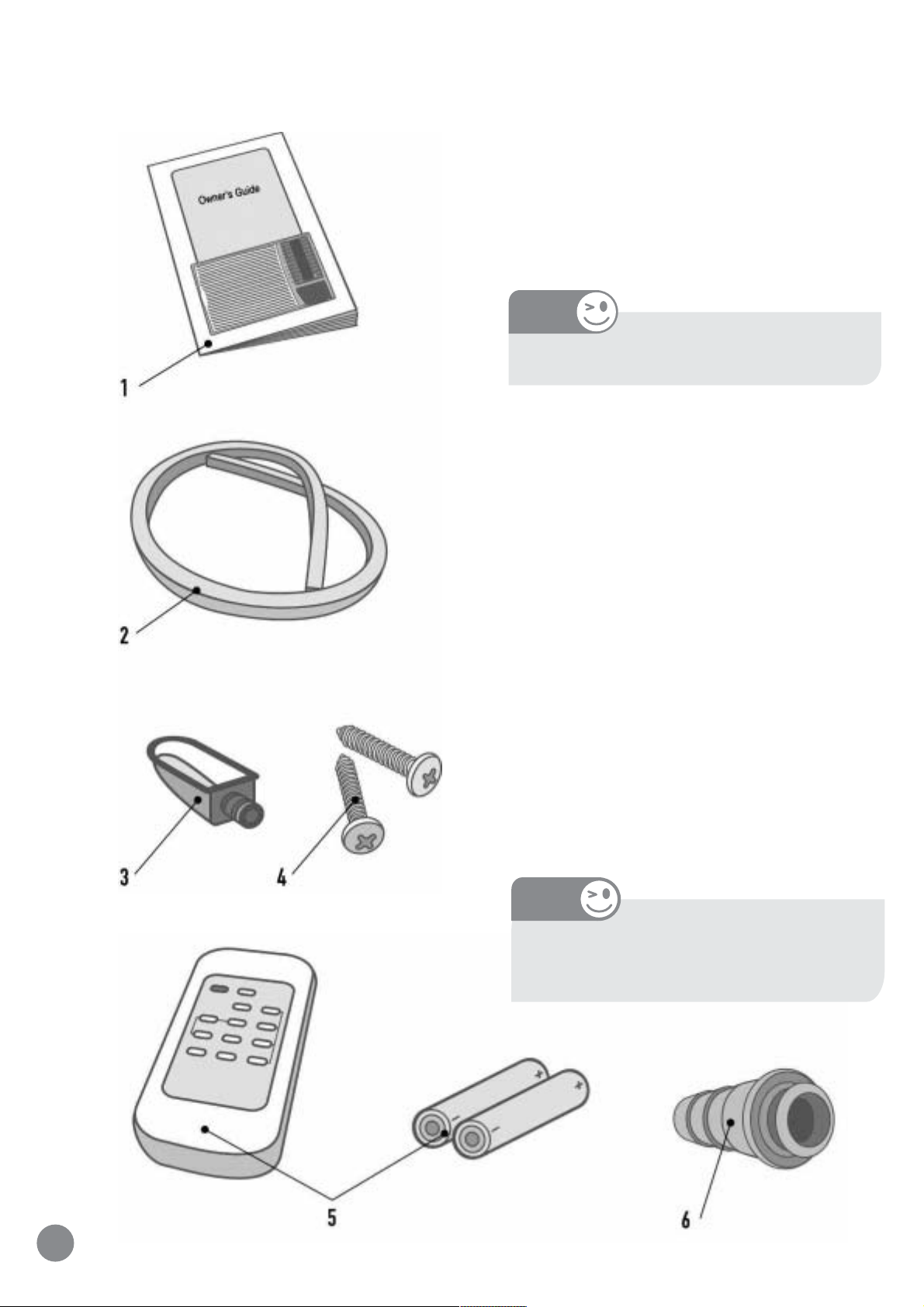
Unpack the unit.
NOTE
For your safety wear gloves.
Check if the unit exterior is in perfect condition.
Check if the items provided with the unit are inside the
box.
1 - User's Manual
2 - Seal
3 - Drain pan
4 - Screws (4)
5 - Remote control and batteries
6 - Rear drain
In case there is any damage, or if one of the mentioned
items is missing, contact the store that sold it to you.
NOTE
The window installation accessory kit
comes with cooling only units.
4
Page 5
2. GETTING ACQUAINTED WITH THE
AIR CONDITIONER
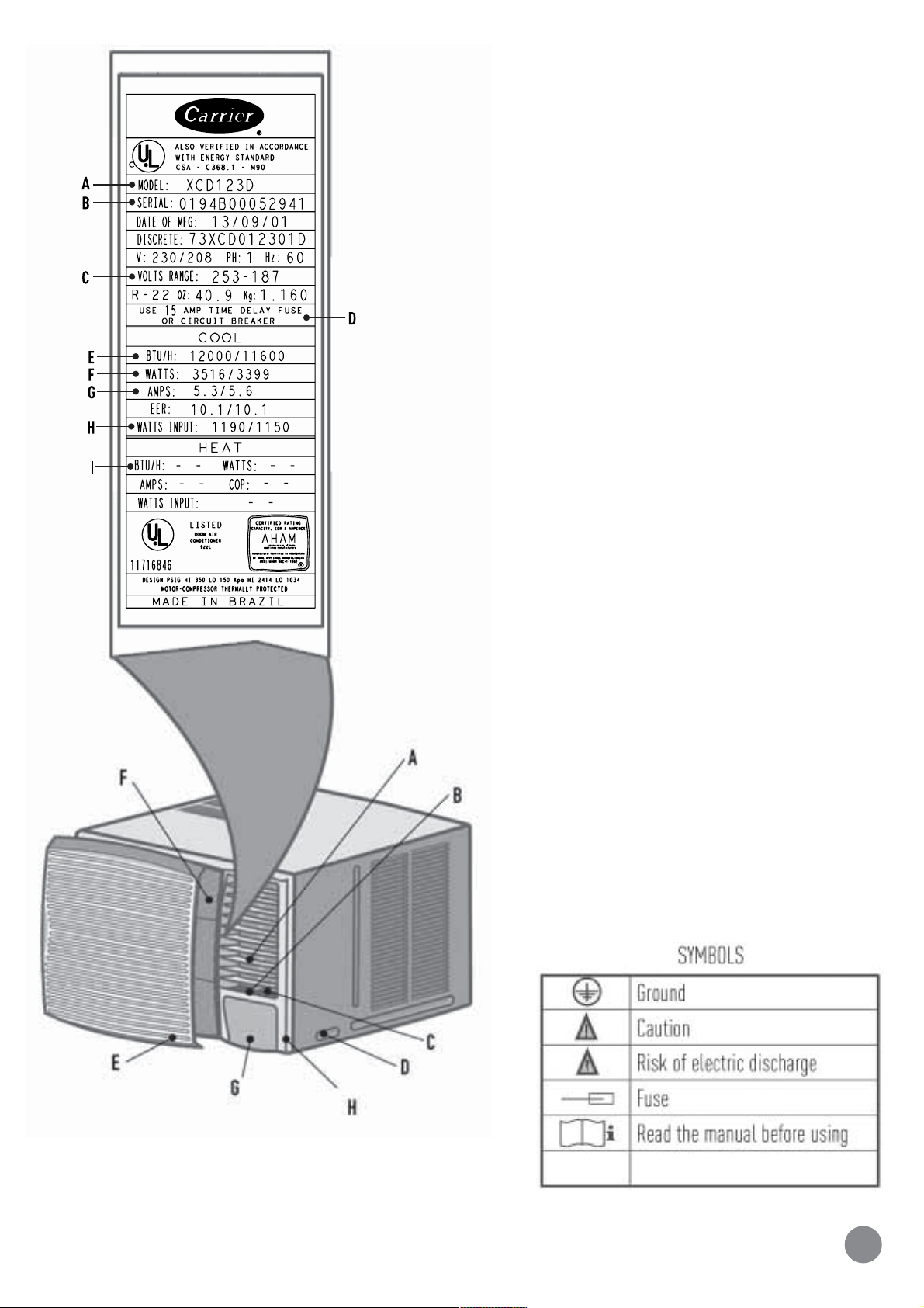
Check the appliance technical characteristics on the
nameplate.
Nameplate
A - Model
B - Serial number
C - Voltage (V)
D - Circuit Breaker (A)
E - Cooling capacity (Btu/h and W)
F - Power consumption (W)
G - Current (A)
H - Power efficiency (W/W)
I - Heating capacity (Btu/h and W)
Cabinet
A - Horizontal louvers for the air flow
B - Vertical louvers for the air flow
C - Air exhaust control
D - Safety screws (both sides)
E - Filter cover
F - Filter
G - Control panel
H - Front Grille
5
Page 6
3. AIR CONDITIONER WITH REMOTE CONTROL
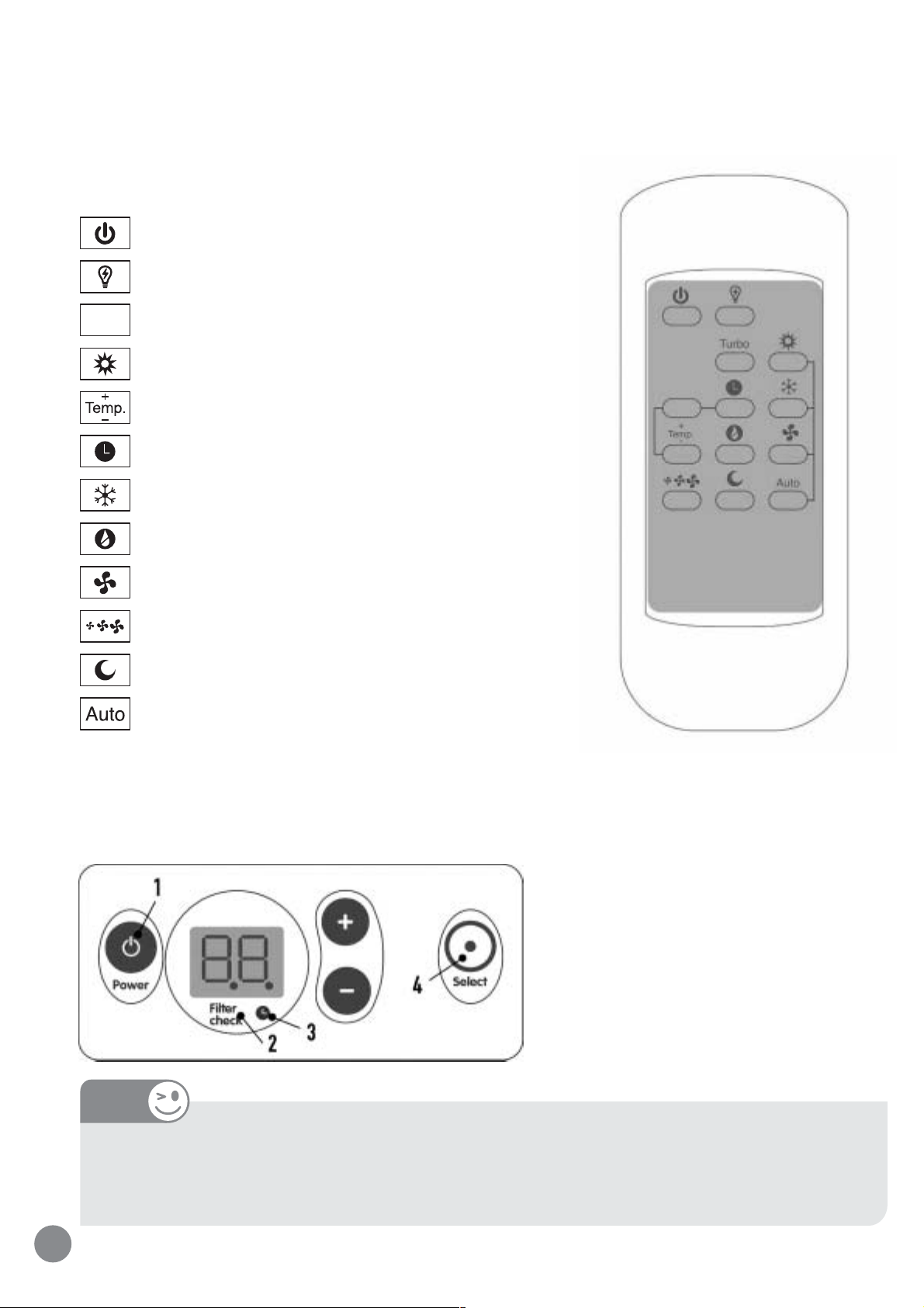
Remote control
On/Off
Energy Saver
Turbo
Turbo mode
Heating mode
Temperature and Timer adjustment
Timer
Cooling mode
De-humidification mode
Fan mode
Speed setting
Sleep mode
Auto mode
Control panel
Main display (indicates the selected temperature or mode)
NOTE
In order to change the temperature unit from Celsius to Fahrenheit degrees, or vice-versa,
simultaneously press the Select button and (+) for 3 seconds on the control panel.
6
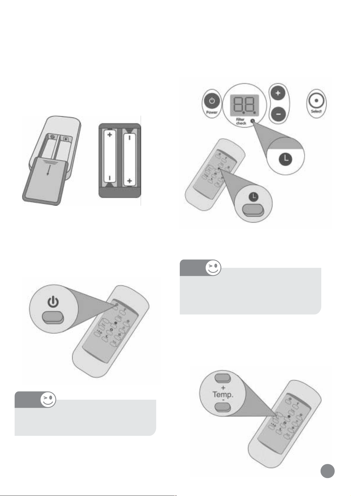
1 - On/Off
2 - Filter cleaning indicator
3 - Timer on indicator
4 - Selector
Page 7
4. OPERATING THE ELECTRONIC
UNIT WITH THE REMOTE CONTROL
Timer operation, turn the unit off or on at a
determined time (from 1 to 12 hours), press the Timer
button. If the unit is off, after the programming, it will
turn on at the end of the set time. If it is on, it will
Insert two 1.5 V AAA batteries (supplied with the
electronic model unit), opening the cover on the rear
of the remote control.
The battery useful life is around one year.
Use only new batteries. Use only specified batteries.
turn off at the end of the period.
When this function is activated, the corresponding
To turn on or off the unit, press the On/Off button.
NOTE
indicator remains lit on the panel.
NOTE
The unit display will turn off 5 minutes
after the mode is activated, and the Timer
indicator will remain lit.
In order to set the time to turn on and off, press the
buttons (+) or (-) until the desired time (in number of
hours) is achieved.
The unit "beeps" every time an
operation is activated.
7
Page 8
These buttons set the time hour by hour, up to 12 hours.
NOTE
To display the room temperature, press buttons (+)
and (-) simultaneously for 3 seconds.
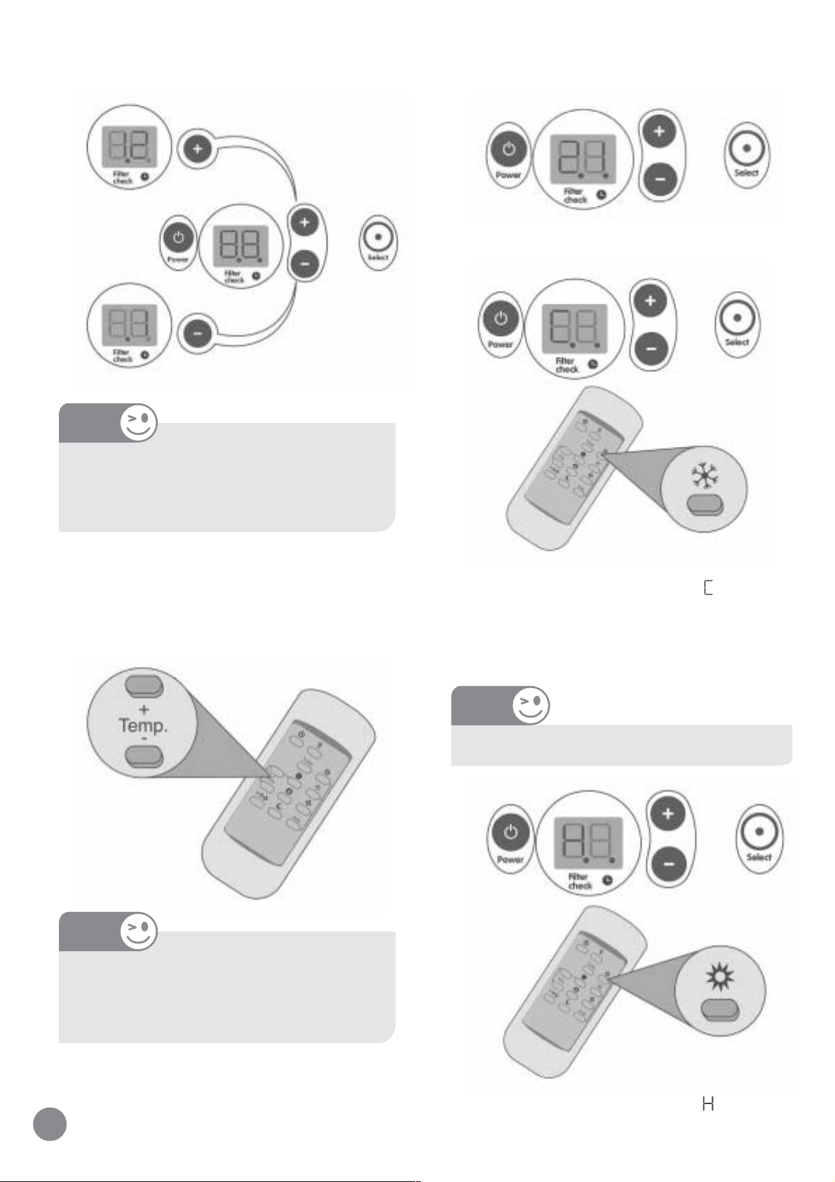
To cool, press the Cooling mode button.
To cancel this function, press the Timer
button again, and set the time to zero.
To increase or reduce the temperature in the room,
press the buttons (+) or (-), as required.
When this function is activated, the letter is displayed
on the panel.
To heat, press the Heating function button.
NOTE
Only for models with heat feature.
NOTE
The temperature ranges from 18ºC / 65°F
to 32ºC / 90°F. To set the maximum or the
minimum, the unit beeps twice.
8
When this function is activated, the letter
on the panel.
is displayed
Page 9
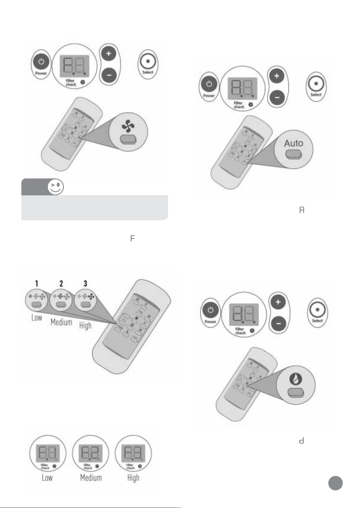
In order to circulate air (without cooling or heating),
To automatically adjust the unit according to the room
press the Fan button.
NOTE
The Fan Function only circulates the air in
the room.
temperature variations, alternating between cool and
heat and high, medium or low speed, activate the Auto
mode.
When this function is activated, the letter
on the panel.
is displayed
When this function is activated, the letter is displayed
on the panel.
To set the fan speed, press the fan speed button.
The speed can be selected among one of the three
existing levels.
To eliminate the air humidity in the room, press the
De-humidification button. This function gradually
removes the room humidity, with little changes to the
temperature, providing more comfort.
The selected speed (air flow) will be indicated on the
control panel as follows:
When this function is activated, the letter
on the panel. The unit will always operate in low cooling.
is displayed
9
Page 10

In order to cool or heat the room quickly, set the
temperature as desired, and press the Turbo mode
NOTE
button.
When this function is activated, the letter T is displayed
on the panel.
The Turbo function will turn off as soon as the selected
temperature is reached, and from then on, it will operate
in last selected mode.
The unit display will turn off 5 minutes
after the mode activation, and the Timer
indicator remains.
To save power, press the Energy Saver button.
To automatically set the room temperature during
sleep time, providing more cost-effectiveness and
comfort, activate the Sleep mode.
After this mode is activated, the unit will increase (in
cooling) or decrease (in heating) the set temperature
in 1ºC / 2°F per hour, during the first two hours,
remaining at this temperature for more than 6 hours.
When the total 8-hour period has elapsed, the unit will
return to the initial temperature. On the display,
will appear (sleep - to sleep).
The Energy Saver function reduces the consumption of
power, turning off the fan when the compressor or
resistance is off. The function is activated and deactivated by means of the remote control. When the
function is activated, the display exhibits the acronym
.
10
Page 11

5. OPERATING UNIT FROM THE CONTROL PANEL
(WITHOUT THE REMOTE CONTROL)
To select any one of the functions on the unit, press
the Select button once, and the function programmed
will appear on the display. Then, press the button (+),
or the button (-), until achieving the desired function.
Release the button, and the unit will take on this new
programming.
Display
- Fan
- Cooling
- De-humidification
- Auto (Automatic)
- Heating (only for HOT/COOL models)
- Turbo
To change the fan speed, press the Select button
twice, and the display will exhibit the programmed
speeds, that is, F1, F2 or F3. Then, press the button
(+), or the button (-), until achieving the new speed.
Release the button, and the unit will take on this
new programming.
- Sleep
- Energy Saver
Next, the desired temperature can be set using the
buttons (+), or (-).
11
Page 12

6. AIR DIRECTION AND EXHAUST
CONTROL
Four way air flow provided by the mobile
louvers.
When the vertical louvers are moved, the air
flow is directed to the left or to the right.
When the horizontal louvers are moved, the
air flow is directed up or downwards.
The air exhaust control is made through the
device located next to the louvers.
IMPORTANT
The Exhaust function allows removing the
used air, smoke, and odors from the room
and sending them to the outside.
The use of exhaust control with the unit in
cooling or heating reduces the unit efficiency.
Therefore, we recommend to use it, whenever
necessary, in the Fan function.
12
Page 13

7. TIPS TO ACHIEVE MAXIMUM
EFFICIENCY AND COMFORT
The air conditioner has been designed to
operate withim the folowing voltage and
temperature conditions.
Keep the air filter clean, and do not turn on the unit
without the air filter.
Do not wait until the room temperature gets too low or
too high. Turn on the unit before that.
Do not exaggerate in the temperature intensity (too hot
or too cold).
Exaggerated temperatures waste energy.
When turning on the air conditioner, keep doors, windows
Voltage
Nominal
115V/60Hz
208-230/60Hz 187V 253V
MAXIMUM OUTSIDE TEMPERATURE
Cooling..............maximum 109ºF (43°C)
Minimum
104V
Maximum
127V
NOTE
For the heating mode on the heat pump
models, the electrical heater start operating.
When the outside temperature drops below
45º F (7º C).
and curtains closed.
These precautions increase the unit efficiency, and
reduce the power consumption.
Before sleeping, set the unit to low speed in order to
reduce the noise level.
Do not use the air conditioner to dry clothes, to preserve
food, and nor to acclimatize environments for animals
or plants.
During long periods when the air conditioner is not
used, turn it on for some minutes once a month. If the
model is HEAT /COOL, turn it on in heating mode.
13
Page 14

8. WHERE AND HOW TO INSTALL
THE AIR CONDITIONER TO ACHIEVE
6. Comply with the minimum distance required for the
installation of more than one unit on a same wall.
A BETTER PERFORMANCE
1. Never obstruct the air circulation of the unit installing
it behind curtains, furniture or partition walls.
2. Try to install the unit on a wall directed toward the
east, because the sunrays are less intense.
3. Avoid using this unit in Cooling with inside temperatures
lower than 20ºC / 68°F, so that the ice does not accumulate
in the inside heat exchanger.
/ 40
7. Avoid installing the outside surface of the air
conditioner turned to closed environments as roof
boards, garages, etc, the outside temperature might go
over the maximum operating temperature and damage
the unit.
4. Install the air conditioner facing the largest
free area.
5. Pay attention to the minimum distances between
the external surface of the unit and the wall near
it.
8. Whenever you want to change from Cooling to Heating,
or vice versa, turn off the appliance, and wait for 3
minutes before turning it on again.
NOTE
The electronic models have an automatic
protective device that allows restarting
the compressor only 3 minutes after the
shutdown.
9. In case of power outage, turn off the air conditioner
immediately, and turn it on again only 1 minute after
the power is re-established. This procedure will prevent
voltage variations that can cause damage to the
compressor.
14
10. Do not use the circuit breaker as an On-Off switch.
The circuit breaker is the main safety device of the
electric circuit.
Page 15

THROUGH-THE-WALL INSTALLATION
Cut opening in wall. For dimensions see Fig. below.
NOTE
Window installation GW 05825004 instructions come
with the window accessory kit only for ZC models. It is
available as an accessory for ZH and ZQ models.
Through-the-wall installation can be made in wood
frame or masonry walls. The casing must be tipped to
the outside to aid in draining condensate. The installation
should be weatherproofed outside and finished
inside.Installations in wood framed or masonry walls
can be made using the casing as follows. Fasten the
casing directly to masonry or studding using masonry
or woodscrews. Adjust the outward tip front to rear, so
it drops from 3/16 to 3/8-in. (5-10-mm). If wall thickness
overlaps the side louver in unit casing,make wall opening
Frame opening in wall. For wood framing,provide
a wooden framing support or other approved
structure for fastening casing to wall. See Fig.
for typical wood framing.
WALL STUD
FINISHED
OPENING
DIMENSIONS
26 3/16” (665mm)
Tipical wood framing
17 5/16”
(440mm)
FRAME OR
BACK UP STRIP
wider, as shown in Fig. below. If wall projects beyond
back of unit, use baffles onrear corners of casing.
3/4
6
(17 cm)
45°
12 (30 cm)
For masonry framing, use a lintel to support wall
above opening. Mouting angles are sometimes
assembled to casing. Be sure to size the wall opening
to provide clearance for metal thickness of casing
and mouting angles if they are used. If mounting
angles are to be used with casing, position angles
as follows:
1. Flush with unfinished wall - plaster over or use
decorative molding.
2. Against finished wall - use decorative molding.
3. Inside wall opening - use decorative molding.
CAUTION
Good framing construction practices must
be followed to ensure a safe, secure and
properly installed unit.
15
Page 16

INSTALL CASING IN WALL
NOTE
Unit casing should project ½ (13mm) in to
room to ensure proper fit of decorative grille.
Remove the two screws that hold the plastic front (one
at each side).
Be careful not to be injured by the metal parts.
Disconnect the ground wire and remove the unit
from the wrapper pulling it by the bottom.
Tip casing to outside. Tip is necessary for draining
Remove the plastic front.
Remove the safety screw.
condensate to the rear of the basepan, to allow for
excess condensation run-off. The tip also helps to
prevent leakage into the room by allowing excess water
to drain away from the building.
The recommended outward tip is 3/16 to 3/8 in. (5 to 10
mm) from inside to outside. This means that back of
casing outside the room must be 3/16 to 3/8 in. (5 to 10
mm) lower than the front edge inside room.
16
Page 17

IMPORTANT
Install the draining system for the condensing water
before positioning the unit in the cabinet. You must use
If unit is installed where condensate
drainage from the back of the unit can
drip onto pedestrians or neighboring
property, use the external drain kit
supplied with the unit. See installation
instructions on drain kit. - Step 9.
Hold tip angle and mark with chalk the location of
screw holes to be drilled in each side of the casing for
fastening in wall opening.
Drill 3 screw holes in each side of wood frame.
Recheck outward tip.
one of the two existing systems, depending on how,
and where the unit will be installed.
9.1 DRAINING SYSTEM THROUGH THE REAR
OUTLET
NOTE
Remove the rear plug from the unit, and
install the drain (item 6, page 4).
NOTE
Chassis is heavy. Obtain help when lifting
to avoid personal injury.
9. DRAIN SYSTEM OPTIONS
The conditioner comes with the two drain holes closed
by plugs.
The conditioner is projected to use one of the three
function options:
1) No drain connection. That way provides the most
efficiency operation, but has splash noise, dripping
Pass a 5/8" (15,9 mm) plastic hose through the hole
located on the rear of the cabinet.
The hose must be long enough to reach the
rain water drain.
of rain water or condensate water.
2) Rear drain, which provides a good efficiency for
operation and very low splash noise, or
3) Drain pan, which captures the most condensate and
does not have splash noise, but has lower efficiency
operation. Both the rear drain and the drain pan can
be connected to a hose and directed to a convenient
location on the ground, or a suitable floor drain.
17
Page 18

Install one of the hose ends at the drain outlet.
9.2 DRAINING SYSTEM THROUGH THE BOTTOM
The other end of the hose must be connected to the
water mains.
OUTLET (USING THE DRAIN PAN)
The installation of this draining system is
not recommended when the unit is
installed on sites with difficult access
(example: far from windows and inside
buildings), because it is difficult to connect
the hose to the water mains.
Position the drain pan inside the cabinet.
Install a 5/8" (15,9 mm) plastic hose at the outlet of
the drain pan.
The hose must be long enough to reach the
18
rain water drain.
Page 19

The other end of the hose must be connected to the
rain water drain.
IMPORTANT
Remove the existing plug in the inside
portion of the unit, the "highest one",
located next to the letter "A".
INSTALLING THE UNIT IN THE CABINET
Two people must install the unit on the cabinet in order
to guarantee its perfect balance and alignment.
Take care not to crease or bend the hose.
The installation of this draining system is
recommended for most kinds of
installation (for example: on walls with
sash or on windows), since this makes
easier to connect the drain hose to the
rain water drain.
IMPORTANT
To get the maximum performance with the
lowest power consumption, we recommend
using the draining system through the rear
outlet.
Lift the unit, align it with the cabinet, and slide it until
it is perfectly inserted.
Install the safety screw on both sides.
19
Page 20

Install the sealing tape and the flashing finishing.
NOTE
ELECTRICAL DATA
1. All wiring must comply with local and national electrical
codes. All wiring must be installed by qualified and
Sealing tape and flashing are not included with
machine.
Positioning the cable on the power outlet side
skilled electricians. If you have any questions regarding
the following instructions, contact a qualified electrician.
2. Check available power supply and solve any household
wiring problems BEFORE installing and operating this
unit.
3. An individual branch circuit and single receptacle used
only for this air conditioner, must be available. See Table
1 for suggested wire sizes for individual branch circuit.
4. For your safety and protection, this unit is grounded
through the power cord plug when plugged into a matching
wall outlet. If you are note sure whether your wall
outlet is properly grounded, please consult a
qualified electrician.
5. The wall outlet you select must macth the plug on the
unit power cord, and must be within reach of the installed
unit.
The unit is prepared for this condition.
Install the plastic front, fastening it with two screws
NOTE
Power cord is 55 in. (1,4 m) long and extends from
bottom of control panel. See Step 24, if power cord
must be relocated to opposite side of unit. Do NOT
use a plug adapter or extension cord.
6. Follow fuse specifications indicated on unit
nameplate. See Table 2. Nameplate is located
above unit control panel inside the air discharge
section. For clear access to nameplate, front grille
must be removed as described on page 6.
NOTE
Unit model/catalog number, service/discrete number,
and serial number can be found on the nameplate.
When calling for information and service, be sure
to provide the service/discrete number.
(one on each side).
20
Page 21

To test your power supply cord:
1. Plug power supply cord into a grounded 3-prong outlet.
2. Press RESET.
3. Press TEST (listen for click; Reset button will trip and pop out)
4. Press and release RESET (listen for click; Reset button will latch and
remain in). The power supply cord is ready for operation.
POWER SUPPLY CORD
NOTE
Power cord is 55 in. (1,4 m) long and extends from
bottom of control panel. See Step 24, if power cord
must be relocated to opposite side of unit. Do NOT
use a plug adapter or extension cord.
NOTES
o
The Reset button must be pushed in for proper
operation.
o
The power supply cord must be replaced if it
fails to trip when the test button is pressed or
fails to reset.
o
Do not use the power supply cord as an off/on
switch. The power supply cord is designed as a
protective device.
o
A damaged power supply cord must be replaced
with a new power supply cord obtained from the
product manufacturer and must not be repaired.
o
The power supply cord contains no use
serviceable parts. Opening the tamper-resistant
case voids all warranty and performance claims.
This room air conditioner is equipped with a power supply
cord required by UL (Underwriters Laboratories). This power
supply cord contains state-of-the-art electronics that sense
leakage current. If the cord is crushed, the electronics detect
leakage current and power will be disconnected in a fraction
of a second.
21
Page 22

10. SAFETY INSTRUCTIONS
Do not allow children to operate the unit.
11. MAINTENANCE AND
PRESERVATION
During thunderstorms, turn off the unit on the panel, or
on the remote control, and turn off the circuit breaker,
too.
To clean the unit, always turn off the circuit breaker.
Do not turn the unit off at the socket.
Do not touch the power supply cable or any other electric
component of the unit with wet hands.
Never insert objects or fingers in the openings of the unit
because this can injure you.
Do not attempt to repair the unit if you are not duly
qualified.
Call the Authorized Carrier Technical Assistance Service.
If the air conditioner has a remote control, keep it in a
safe location, to prevent breakage or loss.
CLEANING OF THE PLASTIC FRONT AND OF
THE CABINET
To clean the plastic front and the cabinets, use a soft
cloth soaked in warm water and neutral detergent.
The filter door can be
removed for cleaning
purposes.
When cleaning, do not use steel sponge or any other
OPERATION WITH POWER OUTAGE
IMPORTANT
In case of a power outage while the unit
is running, the operating conditions will
be memorized and re-established when
the unit is turned on again. However, the
unit will not turn on automatically with
the recovery of the power.
The TIMER programming will be cancelled.
When you leave home during a power
outage, disconnect the unit from the
socket, to prevent it from turning on
abrasive product. This can scratch the unit.
Abrasive product
Steel sponge
Do not apply detergent, alcohol or water
directly to the plastic front.
automatically when the power is reestablished.
22
Page 23

CLEANING OF THE AIR FILTER
An obstructed air filter reduces the capacity of the air
conditioner, and increases the power consumption.
Check it monthly.
Do not use the air conditioner without the filter, since
the dust and the impurities will damage it, or require
a specialized cleaning.
Cleaning by vacuum: pass the vacuum cleaner hose
nozzle to remove the dust accumulation.
Washing: position the filter with the dirty part turned
downwards, and let the water run on it. This way, all the
dirt and impurities will be easily removed.
Install the filter with the knob downwards.
For electronic conditioners, there is an indicator (
that warns when the filter needs to be cleaned.
After cleaning, press simultaneously for 3 seconds, the
Select button and the (-) button, and the indicator light
will turn off.
The air conditioner filter can be cleaned by vacuum or
washing.
Before starting to clean, turn
)
Close the plastic front.
off the unit, and open
the plastic front.
Remove the filter.
INTERNAL CLEANING AND GENERAL
INSPECTION
The unit must be internally cleaned, at least once a year,
by a specialized technician of the Authorized Technical
Assistance.
If the unit is installed in a dusty environment, or operated
during many hours a day, the internal cleaning must be
made more frequently.
NOTE
This service is not covered by the
Warranty.
23
Page 24

12. PRACTICAL SOLUTIONS
Before calling an Authorized Technical Assistance, see how to act in case the air conditioner presents any of the
failures below:
OCCURRENCE PROBABLE CAUSES SOLUTIONS
The air conditioner
does not operate
The air conditioner does
not cool or does not
heat properly
Inside heat exchanger
is frozen
Water leaks to the
inside of the room
1. Circuit breaker off
2. Power supply cable disconnected from the electric current
3. Power failure
1. Dirty air filter
2. Obstruction in the air flow
3. Open room
4. Heat source in the room
5. Thermostat button improperly positioned
6. Unit improperly dimensioned for the room
7. Strong sunrays entering into the room
1. Insufficient air circulation
2. Dirty air filter
1. Obstructed drain
2. Incorrect installation.
3. Cabinet installed without the outward inclination
1. Turn on the circuit breaker again
2. Connect the cable to the socket
3. Wait until the power supply is re-established
1. Clean the air filter
2. Remove the obstructions: curtains, couches, etc.
3. Close the doors and windows
4. Eliminate the heat source
5. Adjust the conditioner controls properly
6. Redefine the unit model choosing a proper one for
the room
7. Block the rays, but do not obstruct the air flow
1. Unobstruct the appliance front
2. Clean the air filter
1. Unobstruct the drain
2. Correct the installation, according to the instructions
of this Manual
3. Correct the inclination, as described in this Manual
Compressor does not
start
Water noise in the
appliance
Message on the display
(electronic models)
E4
E5
FL
Remote control does not
operate
If the failure persists, and cannot be solved in accordance with the directions, turn off the appliance, and do not try to restart it. Request the
assistance of the nearest Authorized Service. For that, refer to the enclosed list of authorized offices.
1. Voltage below the normal level (115V or 220V)
2. Unit turned off, and turned on immediately after
1. Excessive accumulation of condensation water
inside the appliance
1. Failure in the inside temperature sensor
2. Failure in the outside temperature sensor
3. Dirty filter
1. Batteries without charge
2. Damaged remote control
1. Contact the power supply services in your region
2. Wait 3 minutes to turn on again
1. Use the Draining System through the bottom outlet
(using the drain pan)
1. Contact the Authorized Technical Assistance
2. Contact the Authorized Technical Assistance
3. Clean the filter, following the instructions on page 23
1. Replace the batteries
2. Use the electronic panel until the damaged control
is replaced
24
Page 25

Carrier
Room Air Conditioner
Full Warranty
ONE-YEAR WARRANTY - CARRIER warrants to the user that this product will be free from defects of workmanship under normal
use and maintenance for a period of one year from the date of original purchase. CARRIER, through an independent servicing dealer
or service station, will either repair or replace a defective product (as decided solely by CARRIER) free of charge to the user. CARRIER
may replace any defective part with either a new or remanufactured part, at CARRIER's sole option.
EXTENDED FOUR-YEAR WARRANTY ON SEALED REFRIGERATION SYSTEM ONLY - During the second through fifth years after
date of original purchase, CARRIER further warrants to the user that the compressor, condenser, evaporator, and connecting tubing
will be free from defects in material or workmanship under normal use and maintenance. CARRIER will either repair or replace (as
decided solely by CARRIER) any defective compressor, condenser, evaporator, or connecting tubing free of charge to the user, including
a recharge of refrigerant for the system if necessary. However, THIS LIMITED WARRANTY DOES NOT INCLUDE costs incurred for
diagnosing, removing, installing, shipping, or transporting the product or any parts. User is responsible for these costs; however,
SUCH COSTS MAY BE COVERED by a separate warranty or service agreement provided by the seller or another third party, such
agreement being separate and distinct from this factory warranty.
LIMITATION OF WARRANTIES - ALL IMPLIED WARRANTIES (INCLUDING IMPLIED WARRANTIES OF MERCHANTABILITY AND FITNESS
FOR A PARTICULAR PURPOSE) ARE HEREBY LIMITED IN DURATION TO THE PERIOD FOR WHICH HEREIN. Some states do not allow
limitations on how long an implied warranty lasts, so the above limitations may not apply to you. THE EXPRESS WARRANTIES MADE
IN THIS WARRANTY ARE EXCLUSIVE AND MAY NOT BE ALTERED, ENLARGED, OR CHANGED BY ANY DISTRIBUTOR, DEALER, OR OTHER
PERSON WHATSOEVER. CARRIER WILL NOT BE RESPONSIBLE FOR ANY SPECIAL, INCIDENTAL, OR CONSEQUENTIAL PROPERTY OR
COMMERCIAL DAMAGES OF ANY NATURE WHATSOEVER. Some states do not allow the exclusion of incidental or consequential
damages, so the above limitation may not apply to you. All work provided for by this warranty shall be performed during normal
working hours. All replacement parts, whether new or remanufactured, assume as their warranty period only the remaining time
period for which the applicable component is expressly warranted herein.
CARRIER WILL NOT BE RESPONSIBLE FOR:
1. Damage due to faillure to perform normal maintenance as outlined in the Owner's Guide.
2. Instruction on methods of control and use of air conditioning unit after initial installation.
3. Damage or repairs needed as a consequence of faulty installation or application. This is the reponsibility of the installer.
4. Failure to start due to voltage conditions, blown fuses, open circuit breakers, or any other damages due to the inadequacy or
interruption of electrical service.
5. Damage or repairs needed as a consequence of any misapplication, abuse, unauthorized alteration, improper servicing or operation.
6. Damage as a result of floods, winds, fires, lightning, accidents, corrosive environments, or other conditions beyond the control
of CARRIER.
7. Any parts not supplied or designated by CARRIER.
8. CARRIER products installed outside the continental U.S.A., Alaska, Hawaii, and Canada.
9. Shipping damage or damage as a result of storing or transporting the unit.
Form No. 530-048(Rev. 7/92)
This warranty gives you specific legal rights, and you may also have other rights which vary from state to state.
25
Page 26

CARRIER CORPORATION
IF YOUR UNIT DOES NOT WORK, FOLLOW THESE STEPS IN ORDER:
1. CHECK THE THINGS YOU CAN DO YOURSELF. These include being sure the air conditioner is plugged in firmly
in an appropriate receptacle, checking the fuse or circuit breaker and ensuring its replacement or resetting,
if necessary, and rereading the instruction book to ensure all controls are set properly. By doing this you
can save money. Many unnecessary calls result in the serviceman doing what the owner can do for himself.
2. CONTACT YOUR DEALER OR THE CARRIER AUTHORIZED SERVICE CENTER. You may find this name on the
product, on your invoice, or in your Homeowner's Packet.
3. CONTACT THE NEAREST CARRIER DISTRIBUTOR SERVING YOUR AREA. (See Telephone Yellow Pages.)
4. CONTACT CARRIER IF A SATISFACTORY SOLUTION IS NOT REACHED IN STEPS 2 AND 3.
Carrier Air Conditioning
Consumer Relations Department
P.O. Box 4808
Carrier Parkway
Syracuse, New York 13221
Telephone: 1-800-CARRIER (227-7437)
From Canada: (315) 432-7885
Model/Catalog No
Service/Discrete
Date of Installation
Name of Owner
Unit Serial No
Installed By
Address of Installation
26
Page 27

Page 28

GW256.08.003 - 12/06
 Loading...