

Page 1

Single Package Gas Heating and Electric Cooling Units
with Direct Spark Ignition and COMFORTLINK™ Controls
Installation Instructions
WEATHERMASTER
48ZG,ZN030-105
48ZT,ZW,Z6,Z8075-105
®
CONTENTS
Page
GENERAL . . . . . . . . . . . . . . . . . . . . . . . . . . . . . . . . . . . . . . . . 1
SAFETY CONSIDERATIONS . . . . . . . . . . . . . . . . . . . . .1,2
INSTALLATION . . . . . . . . . . . . . . . . . . . . . . . . . . . . . . . . 2-59
Jobsite Survey . . . . . . . . . . . . . . . . . . . . . . . . . . . . . . . . . . . 2
Unit Placement . . . . . . . . . . . . . . . . . . . . . . . . . . . . . . . . . . . 2
Roof Mount . . . . . . . . . . . . . . . . . . . . . . . . . . . . . . . . . . . . . . 2
Slab Mount. . . . . . . . . . . . . . . . . . . . . . . . . . . . . . . . . . . . . . . 2
Curb Gasketing . . . . . . . . . . . . . . . . . . . . . . . . . . . . . . . . . . 2
Field-Fabricated Ductwork . . . . . . . . . . . . . . . . . . . . . . . 2
Rigging . . . . . . . . . . . . . . . . . . . . . . . . . . . . . . . . . . . . . . . . . . 2
Condensate Drain Connections . . . . . . . . . . . . . . . . . 23
Install Outdoor Hoods
(48ZG,ZN,Z6,Z8 Units). . . . . . . . . . . . . . . . . . . . . . . . . 33
• UNIT SIZES 030-050
• UNIT SIZES 055-105
Install Economizer Hoods (48ZT,ZW Units) . . . . . . 35
• INSTALL SMALL HOODS
• INSTALL LARGE HOODS
Field Wire Routing . . . . . . . . . . . . . . . . . . . . . . . . . . . . . . 36
• UNIT SIZES 030-050
• UNIT SIZES 055-105
Field Electrical Connections . . . . . . . . . . . . . . . . . . . . 36
•POWER WIRING
Air Pressure Tubing . . . . . . . . . . . . . . . . . . . . . . . . . . . . . 51
• INLET GUIDE VANES
• VARIABLE FRQUENCY DRIVE
• MODULATING POWER EXHAUST
• RETURN/EXHAUST POWER EXHAUST
Supply-Fan Shipping Brackets . . . . . . . . . . . . . . . . . . 53
• UNIT SIZES 030-050
• UNIT SIZES 055-070
• UNIT SIZES 075-105
Return/Exhaust Fan Shipping Brackets
(48Z6,Z8 Units). . . . . . . . . . . . . . . . . . . . . . . . . . . . . . . . 53
Remove TXV Shipping Blocks. . . . . . . . . . . . . . . . . . . 54
Compressor Mounting . . . . . . . . . . . . . . . . . . . . . . . . . . 55
Gas Piping . . . . . . . . . . . . . . . . . . . . . . . . . . . . . . . . . . . . . . 55
Optional Staged Gas Control . . . . . . . . . . . . . . . . . . . . 55
Installing Flue/Inlet Hoods . . . . . . . . . . . . . . . . . . . . . . 56
Supply Air Thermistors
(Staged Gas Units Only) . . . . . . . . . . . . . . . . . . . . . . 56
Install Unit Accessories . . . . . . . . . . . . . . . . . . . . . . . . . 59
CONTROLS INSTALLATION . . . . . . . . . . . . . . . . . . 59-66
Constant Volume Units. . . . . . . . . . . . . . . . . . . . . . . . . . 59
• CONTROL WIRING
Variable Air Volume Units . . . . . . . . . . . . . . . . . . . . . . . 59
Optional and Accessory Control Wiring . . . . . . . . . 60
Carrier Comfort Network
Smoke Control Modes. . . . . . . . . . . . . . . . . . . . . . . . . . . 61
®
(CCN) Interface. . . . . . . 60
GENERAL
This installation instruction contains basic unit installation
information, including installation of thermostats and remote
temperature sensors.
For additional information and service instructions, refer to
the Controls and Troubleshooting literature also enclosed in
this literature packet.
The 48ZT,ZW units are equipped with standard integral
economizer and high-capacity power exhaust.
The 48Z6,Z8 units are equipped with factory-installed
return/exhaust fans.
The staged gas control (SGC) option adds the capability to
control the rooftop unit’s gas heating system to a specified supply air temperature set point for purposes of tempering a cool
mixed-air condition.
SAFETY CONSIDERATIONS
Installation and servicing of air-conditioning equipment can
be hazardous due to system pressure and electrical components. Only trained and qualified service personnel should
install, repair, or service air-conditioning equipment.
Untrained personnel can perform basic maintenance functions of cleaning coils and filters and replacing filters. All
other operations should be performed by trained service personnel. When working on air-conditioning equipment, observe
precautions in the literature, tags and labels attached to the unit,
and other safety precautions that may apply.
Follow all safety codes, including ANSI (American National Standards Institute) Z223.1. Wear safety glasses and work
gloves. Use quenching cloth for unbrazing operations. Have
fire extinguisher available for all brazing operations.
WARNING
Before performing service or maintenance operations on
unit, turn off main power switch to unit. Electrical shock
could cause personal injury.
FOR YOUR SAFETY
WHAT TO DO IF YOU SMELL GAS
Do not try to light any appliance. Do not touch any electrical switch; do not use any phone in your building. Immediately call your gas supplier from a neighbor’s phone.
Follow the gas supplier’s instructions. If you cannot reach
your gas supplier, call the fire department.
FOR YOUR SAFETY
Do not store or use gasoline or other flammable vapors and
liquids in the vicinity of this or any other appliance.
WARNING
Improper installation, adjustment, alteration, service, or
maintenance can cause injury or property damage. Refer to
this manual. For assistance or additional information, consult a qualified installer, service agency, or the gas supplier.
Manufacturer reserves the right to discontinue, or change at any time, specifications or designs without notice and without incurring obligations.
Catalog No. 04-53480060-01 Printed in U.S.A. Form 48Z-8SI Pg 1 4-09 Replaces: 48Z-7SI
Page 2
CAUTION
Disconnect gas piping from units when leak testing at pressures greater than 0.5 psig. Pressures greater than 0.5 psig
will cause gas valve damage resulting in a hazardous
condition. If gas valve is subjected to pressure greater than
0.5 psig, it must be replaced. When pressure testing fieldsupplied gas piping at pressures of 0.5 psig or less, the unit
connected to such piping must be isolated by manually
closing the gas valve.
INSTALLATION
Jobsite Survey —
installation.
1. Consult local building codes and the NEC (National
Electrical Code) (ANSI/NFPA [National Fire Protection
Association] 70) for special installation requirements.
2. Determine unit location (from project plans) or select unit
location.
3. Check for possible overhead obstructions which may interfere with unit lifting or rigging.
Complete the following checks before
CAUTION
Do not lift unit with forklift truck. Move unit with overhead rigging only.
Unit Placement — Inspect unit for transportation dam-
age. File claim with transportation agency.
Provide clearance around and above unit for airflow, safety,
and service access. Do not restrict top (area above condenser
fans) in any way. Allow at least 6 ft on all sides for rated performance, code compliance, and service.
Check unit dimensional drawings for unit arrangement and
minimum performance and service clearances.
Do not install unit in an indoor location. Do not locate air inlets near exhaust vents or other sources of contaminated air.
On units equipped with power exhaust option, high velocity
air is exhausted out the hood. Unit should be positioned with at
least 10 ft clearance between the exhaust hood and any obstruction. Although unit is weatherproof, guard against water from
higher level runoff and overhangs.
Level by using unit frame as a reference. Physical data is
shown in Tables 1A-6.
Roof Mount — Check building codes for weight distribu-
tion requirements. Unit weight is shown in Tables 1A-1E and
2. Unit may be mounted on class A, B, or C roofing material.
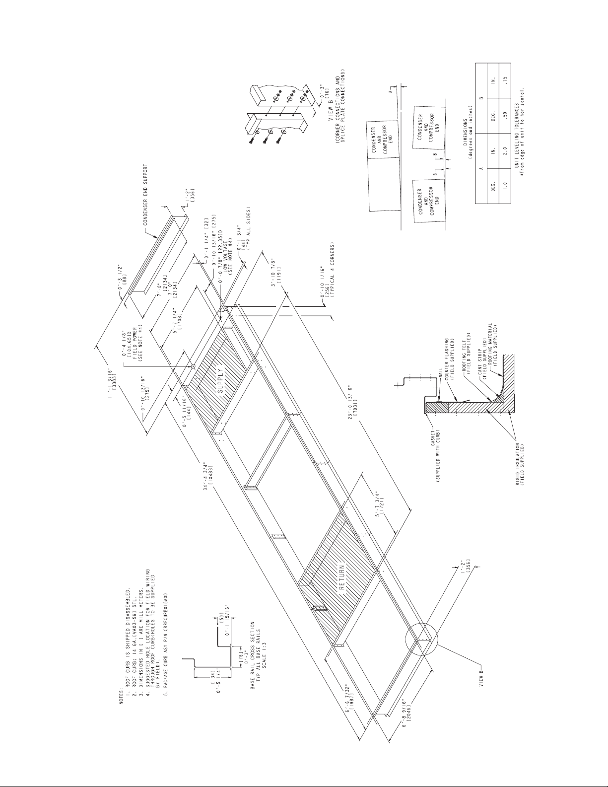
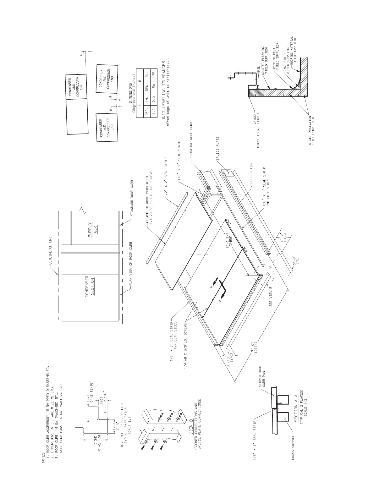
ROOF CURB — Assemble and install roof curb as described
in instructions shipped with the accessory. Accessory roof curb
and information required to field fabricate a roof curb is shown
in Fig. 1-5. Install insulation, cant strips, roofing and counter
flashing as required. For unit condensate drain to function
properly, curb must be level or within tolerances shown in
Fig. 1-5.
STEEL BEAMS — If roof curb is not used, support unit with
steel beams along its entire length and then support steel as required. As a minimum, unit must be supported across its width
at each lifting lug location.
Slab Mount — Provide a level concrete slab that extends
beyond unit cabinet at least 6 inches. Make a slab 8 in. thick
with 4 in. above grade. Use gravel apron in front of condenser
coil air inlet to prevent grass and foliage from obstructing
airflow. Ensure that slab is of sufficient height to allow for condensate trap of 4 in. on sizes 030-070 or 7 in. on sizes 075-105.
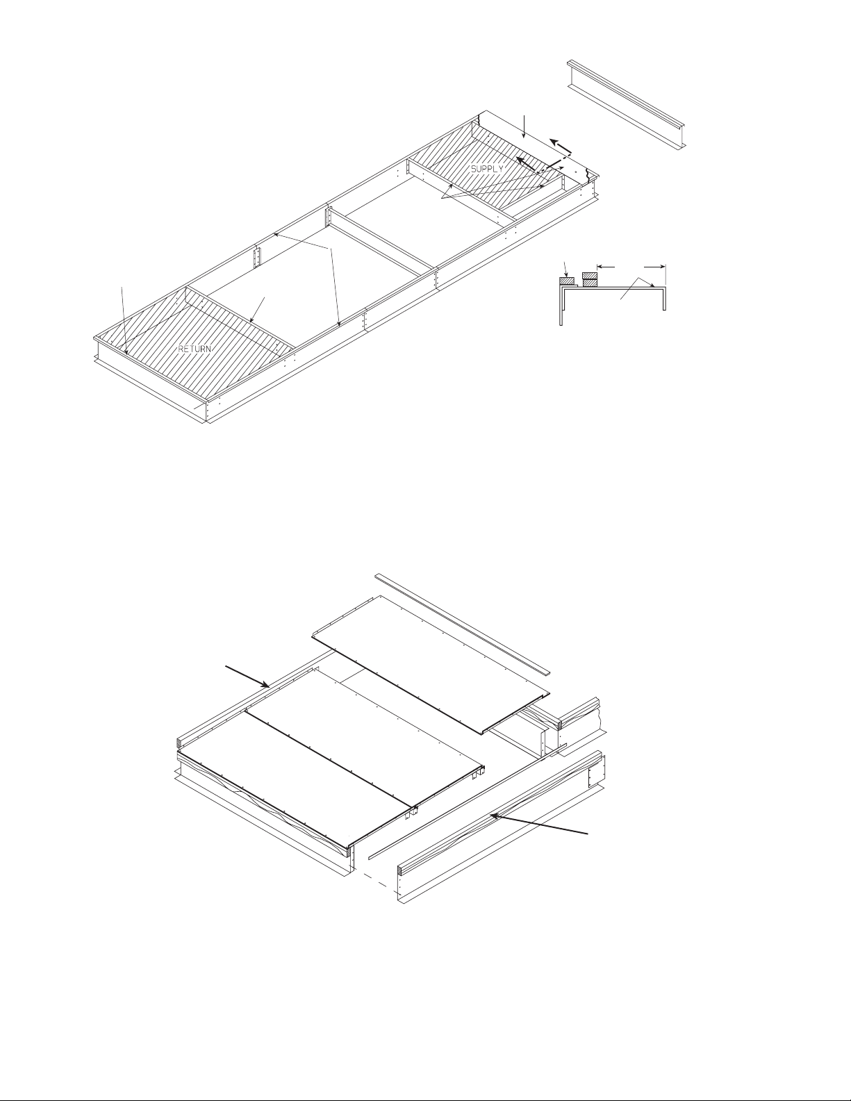
Curb Gasketing
SIZE 030-050 UNITS — After ductwork has been connected
to the roof curb, attach adhesive-backed gasketing on all end
rails, cross rails, and duct rails. Be sure all joints and corners of
gasket are square and flush to prevent possible water leaks.
Follow all applicable building codes.
SIZE 055-105 UNITS — After ductwork has been connected
to the roof curb, apply gasket material (
wide neoprene) where indicated.
Single-Thickness Gasketing (See Fig. 6-8 for Item Numbers) — Apply gasketing in the following places:
1. Along both side rails (1) — 2 places, full length
2. Along return air end rail (2) — 1 place
3. Around return air internal duct flange (3) — 1 or 2 places
4. Around supply air internal duct flanges (4) — 3 places
Double-Thickness Gasketing (See Fig. 6 and 8 and Detail
A-A) — Locate a line 93/4-in. from the supply air end of the
accessory curb. Apply a double-thickness of gasket material
along with line per detail A-A.
NOTE: Do not apply gasket material along the outside edge of
the curb (area “X”). This pan area of the curb extends out
beneath the end of the unit’s air handler section; applying gasket here develops a potential water trap area on top of the curb.
Condenser Section Roof Curb (See Fig. 7)
thickness gasket along both side rails (5).
1
/2-in. thick x 11/2-in.
— Apply single-
Field-Fabricated Ductwork
WARNING
For vertical supply and return units, tools or parts could
drop into ductwork and cause an injury. Install a 90-degree
turn in the supply and return ductwork between the unit
and the conditioned space. If a 90-degree elbow cannot be
installed, then a grille of sufficient strength and density
should be installed to prevent objects from falling into the
conditioned space. Failure to follow these instructions
could result in personal injury or property damage due to
falling objects.
The 48ZG,ZN,ZT,ZW,Z6,Z8 units are designed for vertical
supply/return only. Field-fabricated ductwork must be attached
to the roof curb, on to the support steel, prior to the final rigging
and installation of the unit. Supply and return duct dimensions
are shown in Fig. 1-3.
To attach ductwork to roof curb, insert duct approximately 10
to 11 in. up into roof curb. Connect ductwork to 14-gage roof
curb material with sheet metal screws driven from inside the duct.
Secure all ducts to the building structure, using flexible duct
connectors between roof curbs and ducts as required. Ducts
passing through an unconditioned space must be insulated and
covered with a vapor barrier. Outlet grilles must not lie directly
below unit discharge. The return duct must have a 90-degree
elbow before opening into the building space if the unit is
equipped with power exhaust.
Design supply duct strong enough to handle expected static
pressures.
Rigging — Do not drop unit; keep upright. Use spreader
bars over unit to prevent sling or cable damage. Sheets of plywood placed along the condenser coils will provide additional
protection. All lifting lugs MUST be used when lifting unit.
Level by using unit frame as a reference. See Fig. 9-13 for information. Unit and accessory weights are shown in Tables 1A1E and 2. Weight distribution and center of gravity can be
found in Fig. 14.
2
Page 3
Table 1A — Physical Data (48ZG,ZN030-050)
BASE UNIT 48ZG,ZN030 48ZG,ZN035
NOMINAL CAPACITY (tons) 30 35
OPERATING WEIGHT (lb) Standard Chassis Extended Chassis Standard Chassis Extended Chassis
Base Unit
Low Heat 5640 6140 5766 6266
High Heat 5770 6270 5895 6395
With Economizer
Low Heat 5941 6441 6066 6566
High Heat 6070 6570 6195 6695
COMPRESSORS Semi-Hermetic
Quantity...Type 2...06D 1...06D, 1...06E
Oil Charge (pints) 88, 14
Capacity Steps (%)
CV 50,100 43,100
VAV 17,33,50,67,83,100 14,28,42,57,71,86,100
Number of Refrigerant Circuits 22
REFRIGERANT R-22
Operating Charge (lb), Ckt 1/Ckt 2
Standard Evaporator Coil 29.0/29.0 29.0/30.5
Standard Evaporator with HGBP 31.0/29.0 31.0/30.5
Alternate High-Capacity Evaporator Coil N/A N/A
Alternate High-Capacity Evaporator with HGBP N/A N/A
CONDENSER COILS
Quantity 22
Rows...Fins/in.
Aluminum 3...15.0 3...15.0
Copper (Optional) 3...13.7 3...13.7
Total Face Area (sq ft) 37.5 37.5
EVAPORATOR COILS
Quantity 1
Total Face Area (sq ft) 32.1
Refrigerant Feed Device...No. per Circuit TXV...1
Standard Evaporator Coils
Rows...Fins/in. 3...15.0 4...15.0
Fin Type Double Wavy Double Wavy
Tube Type Cross Hatched Cross Hatched
Alternate, High-Capacity Evaporator Coils N/A N/A
Rows...Fins/in. N/A N/A
Fin Type N/A N/A
Tube Type N/A N/A
HEATING SECTION Low Heat High Heat Low Heat High Heat
Number of Heat Exchangers 1212
Input (MBtuh) 325 650 325 650
Output (MBtuh) 263 527 263 527
Temperature Rise Range (F) 10-40 25-55 10-40 25-55
Efficiency (%) 81 81 81 81
Burner Orifice Diameter
Quantity (in. ...drill no.) 7 (.1285...30) 14 (.1285...30) 7 (.1258...30) 14 (.1258...30)
Manifold Pressure (in. wg) 3.3 3.3 3.3 3.3
Line Pressure (in. wg) (min...max) 5.0...13.0 5.0...13.0 5.0...13.0 5.0...13.0
Firing Stages 2222
Number of Gas Valves 1212
CONDENSER FANS Propeller Type
Quantity...Diameter (in.) 2...30 2...30
Nominal Cfm 18,600 18,600
Motor Hp...Rpm 1.0...1140 1.0...1140
SUPPLY FAN Centrifugal 25 x 25 in.
Nominal Cfm 10,500 10,500
Maximum Allowable Cfm 15,000 15,000
Maximum Allowable Rpm 900 900
Shaft Diameter at Pulley (in.) 1
SUPPLY-FAN MOTOR AND DRIVE (Any motor available on any unit)
Motor Hp 7.510152025
Motor Frame Size 213T 215T 254T 256T 284T
Efficiency at Full Load (%)
High Efficiency 88.5 89.5 91.0 91.0 91.7
Premium Efficiency 91.7 91.7 93.0 93.6 93.6
Fan Pulley Pitch Diameter (in.) 13.7 13.7 13.7 13.7 13.7
Motor Pulley Pitch Diameter (in.) 3.4 4.3 4.9 5.5 6.5
Resulting Fan Speed (rpm) 438 549 626 703 830
Belts Quantity...Type 2...BX60 2...5VX630 2...5VX630 2...5VX630 2...5VX650
Center Distance Range (in.) 17.74-14.30 17.74-14.30 17.63-14.01 17.63-14.01 16.63-12.87
OPTIONAL POWER EXHAUST Centrifugal, 18 x 15 in. (Any motor available on any unit)
Quantity...Motor Hp 2...3.0 2...5.0 2...7.5 2...10
Motor Frame Size High Eff 56HZ 184T 213T 215T
Efficiency at Full Load (%) High/Premium 81.0/88.5 87.5/89.5 88.5/91.7 89.5/91.7
Fan Pulley Pitch Diameter (in.) High Eff 11 10.4 12 12
Motor Pulley Pitch Diameter Range (in.) High Eff 4.1-3.1 4.7-3.7 6.0-4.8 7.0-5.8
Motor Pulley Pitch Diameter Factory Setup (in.) 4.1 4.2 5.4 6.4
Blower Shaft Diameter at Pulley (in.) 1
Fan Rpm Range 500-656 621-785 717-882 854-1000
Factory Setup Fan Rpm 656 703 800 927
Maximum Allowable Rpm 1000 1000 1000 1000
Belts Quantity...No. High Eff 1...BX71 1...BX71 1...BX77 1...BX79
Center Distance Range (in.) 23.62-26.50 23.62-26.50 23.62-26.50 23.62-26.50
FILTERS
Standard Efficiency Throwaway (Standard) 8...20 x 25 x 2 8...20 x 25 x 2
Quantity...Size (in.) 8...20 x 20 x 2 8...20 x 20 x 2
Medium Efficiency (30%) Pleated (Optional) 8...20 x 25 x 2 8...20 x 25 x 2
Quantity...Size (in.) 8...20 x 20 x 2 8...20 x 20 x 2
High Efficiency (90%) Bag Filters
with High Velocity Prefilters (Optional)
Quantity...Size (in.)
Prem Eff 182T 184T 213T 215T
Prem Eff 11.0 10.4 12 12
Prem Eff 4.1-3.1 4.7-3.7 6.0-4.8 7.0-5.8
Prem Eff 1...BX71 1...BX71 1...BX77 1...BX79
Bag Filter
Prefilter
OUTSIDE AIR SCREENS
Standard Hood (25%) Quantity...Size (in.) None None
OPTIONAL ECONOMIZER FILTER Aluminum Frame, Permanent
Quantity...Size (in.)
7
/
16
1
/2 in. Tube Dia
11
/
16
6...20 x 24 x 22
6...20 x 20 x 22
12...16 x 20 x 2
3...20 x 24 x 2
5...20 x 20 x 2
2...20 x 25 x 1
LEGEND *460-3-60 only.
CV — Constant Volume
HGBP — Hot Gas Bypass
MBtuh — Btuh in Thousands
TXV — Thermostatic Expansion Valve
VAV — Var iabl e Ai r Volu me
17/
16
3
/8-in. Tube Diameter
17/
16
1
/2 in. Tube Dia
111/
16
6...20 x 24 x 22
6...20 x 20 x 22
12...16 x 20 x 2
3...20 x 24 x 2
5...20 x 20 x 1
2...20 x 25 x 1
17/
16
3
Page 4
Table 1A — Physical Data (48ZG,ZN030-050) (cont)
BASE UNIT 48ZG,ZN040 48ZG,ZN050
NOMINAL CAPACITY (tons) 40 50
OPERATING WEIGHT (lb) Standard Chassis Extended Chassis Standard Chassis Extended Chassis
Base Unit
Low Heat 6540 7040 6581 7081
High Heat 6670 7170 6710 7210
With Economizer
Low Heat 6841 7341 6881 7381
High Heat 6970 7470 7010 7510
COMPRESSORS Semi-Hermetic
Quantity...Type 2...06E 2...06E
Oil Charge (pints) 14 19, 14
Capacity Steps (%)
CV 50,100 57,100
VAV 25,50,75,100 18,37,56,63,81,100
Number of Refrigerant Circuits 22
REFRIGERANT R-22
Operating Charge (lb), Ckt 1/Ckt 2
Standard Evaporator Coil 40.0/40.0 41.5/39.0
Standard Evaporator with HGBP 42.0/40.0 43.5/39.0
Alternate High-Capacity Evaporator Coil 50.0/51.0 49.0/49.0
Alternate High-Capacity Evaporator with HGBP 52.0/51.0 51.0/49.0
CONDENSER COILS
Quantity 22
Rows...Fins/in.
Aluminum 3...15.0 3...15.0
Copper (Optional) 3...13.7 3...13.7
Total Face Area (sq ft) 50.0 50.0
EVAPORATOR COILS
Quantity 2
Total Face Area (sq ft) 45.5
Refrigerant Feed Device...No. per Circuit TXV...2
Standard Evaporator Coils
Rows...Fins/in. 3...15.0 4...15.0
Fin Type Double Wavy Double Wavy
Tube Type Cross Hatched Cross Hatched
Alternate, High-Capacity Evaporator Coils
Rows...Fins/in. 6...16.0 6...16.0
Fin Type Double Wavy Double Wavy
Tube Type Cross Hatched Cross Hatched
HEATING SECTION Low Heat High Heat Low Heat High Heat
Number of Heat Exchangers 1212
Input (MBtuh) 325 650 325 650
Output (MBtuh) 263 527 263 527
Temperature Rise Range (F) 10-40 25-55 10-40 25-55
Efficiency (%) 81 81 81 81
Burner Orifice Diameter
Quantity (in. ...drill no.) 7 (.1285...30) 14 (.1285...30) 7 (.1285...30) 14 (.1285...30)
Manifold Pressure (in. wg) 3.3 3.3 3.3 3.3
Line Pressure (in. wg) (min...max) 5.0...13.0 5.0...13.0 5.0...13.0 5.0...13.0
Firing Stages 2222
Number of Gas Valves 1212
CONDENSER FANS Propeller Type
Quantity...Diameter (in.) 3...30 3...30
Nominal Cfm 26,000 26,000
Motor Hp...Rpm 1.0...1140 1.0...1140
SUPPLY FAN Centrifugal 25 x 25 in.
Nominal Cfm 14,000 14,000
Maximum Allowable Cfm 20,000 20,000
Maximum Allowable Rpm 900 900
Shaft Diameter at Pulley (in.) 1
SUPPLY-FAN MOTOR AND DRIVE (Any motor available on any unit)
Motor Hp 7.51015202530*
Motor Frame Size 213T 215T 254T 256T 284T 286T
Efficiency at Full Load (%)
High Efficiency 88.5 89.5 91.0 91.0 91.7 92.4
Premium Efficiency 91.7 91.7 93.0 93.6 93.6 93.6
Fan Pulley Pitch Diameter (in.) 13.7 13.7 13.7 13.7 13.7 12.5
Motor Pulley Pitch Diameter (in.) 3.4 4.3 4.9 5.5 6.5 6.5
Resulting Fan Speed (rpm) 438 549 626 703 830 910
Belts Quantity...Type 2...BX60 2...5VX630 2...5VX630 2...5VX630 2...5VX650 3...5VX630
Center Distance Range (in.) 17.74-14.30 17.74-14.30 17.63-14.01 17.63-14.01 16.63-12.87 16.63-12.87
OPTIONAL POWER EXHAUST Centrifugal, 18 x 15 in. (Any motor available on any unit)
Quantity...Motor Hp 2...3.0 2...5.0 2...7.5 2...10
Motor Frame Size High Eff 56HZ 184T 213T 215T
Efficiency at Full Load (%) High/Premium 81.0/88.5 87.5/89.5 88.5/91.7 89.5/91.7
Fan Pulley Pitch Diameter (in.) High Eff 11 10.4 12 12
Motor Pulley Pitch Diameter Range (in.) High Eff 4.1-3.1 4.7-3.7 6.0-4.8 7.0-5.8
Motor Pulley Pitch Diameter Factory Setup (in.) 4.1 4.2 5.4 6.4
Blower Shaft Diameter at Pulley (in.) 1
Fan Rpm Range 500-656 621-785 717-882 854-1000
Factory Setup Fan Rpm 656 703 800 927
Maximum Allowable Rpm 1000 1000 1000 1000
Belts Quantity...No. High Eff 1...BX71 1...BX71 1...BX77 1...BX79
Center Distance Range (in.) 23.62-26.50 23.62-26.50 23.62-26.50 23.62-26.50
FILTERS
Standard Efficiency Throwaway (Standard) 8...20 x 25 x 2 8...20 x 25 x 2
Quantity...Size (in.) 8...20 x 20 x 2 8...20 x 20 x 2
Medium Efficiency (30%) Pleated (Optional) 8...20 x 25 x 2 8...20 x 25 x 2
Quantity...Size (in.) 8...20 x 20 x 2 8...20 x 20 x 2
High Efficiency (90%) Bag Filters
with High Velocity Prefilters (Optional)
Quantity...Size (in.)
Prem Eff 182T 184T 213T 215T
Prem Eff 11.0 10.4 12 12
Prem Eff 4.1-3.1 4.7-3.7 6.0-4.8 7.0-5.8
Prem Eff 1...BX71 1...BX71 1...BX77 1...BX79
Bag Filter
Prefilter
OUTSIDE AIR SCREENS
Standard Hood (25%) Quantity...Size (in.) None None
OPTIONAL ECONOMIZER FILTER Aluminum Frame, Permanent
Quantity...Size (in.)
7
/
16
1
/2 in. Tube Dia
1
/2 in. Tube Dia
11
/
16
6...20 x 24 x 22
6...20 x 20 x 22
12...16 x 20 x 2
3...20 x 24 x 2
5...20 x 20 x 2
2...20 x 25 x 1
LEGEND
CV — Constant Volume
HGBP — Hot Gas Bypass
MBtuh — Btuh in Thousands
TXV — Thermostatic Expansion Valve
VAV — Var iabl e Ai r Volu me
*460-3-60 only
.
17/
16
3
/8-in. Tube Diameter
17/
16
1
/2 in. Tube Dia
1
/2 in. Tube Dia
111/
16
6...20 x 24 x 22
6...20 x 20 x 22
12...16 x 20 x 2
3...20 x 24 x 2
5...20 x 20 x 1
2...20 x 25 x 1
17/
16
4
Page 5
Table 1B — Physical Data (48ZG,ZN055-070)
BASE UNIT 48ZG,ZN055 48ZG,ZN060 48ZG,ZN070
NOMINAL CAPACITY (tons) 55 60 70
OPERATING WEIGHT (lb) Standard Chassis Extended Chassis Standard Chassis Extended Chassis Standard Chassis
Base Unit
Low Heat 8700 9248 9000 9,548 9,420
High Heat 8820 9368 9120 9,668 9,550
With Economizer
Low Heat 9230 9730 9530 10,030 9,950
High Heat 9350 9850 9650 10,450 10,080
COMPRESSORS Semi-Hermetic
Quantity...Type 2...06E 2...06E 2...06E
Oil Charge (Pints) 19, 14 19 19
Capacity Steps (%)
CV 60,100 50,100 45,100
VAV 20,40,60,80,100 17,33,50,67,83,100 14,29,43,51,66,71,85,100
Number of Refrigerant Circuits 222
REFRIGERANT R-22
Operating Charge (lb), Ckt 1/Ckt 2
Standard Evaporator Coil 59.0/44.5 61.0/61.0 70.5/64.5
Standard Evaporator with HGBP 62.0/44.5 64.0/61.0 73.5/64.5
Alternate High-Capacity Evaporator Coil 72.0/58.0 69.5/69.5 82.5/74.5
Alternate High-Capacity Evaporator
with HGBP
CONDENSER COILS
Quantity 444
Rows...Fins/in.
Aluminum 2...17.0, 3...17.0 3...17.0 3...17.0
Copper (Optional) 2...15.7, 3...15.7 3...15.7 3...15.7
Total Face Area (sq ft) 72.4 72.4 108.4
EVAPORATOR COILS
Quantity 2
Total Face Area (sq ft) 61.5
Refrigerant Feed Device...No. per Circuit TXV...2
Standard Evaporator Coils
Rows...Fins/in. 3...17.0 4...17.0 4...17.0
Fin Type Double Wavy Double Wavy Double Wavy
Tube Type Smooth Smooth Smooth
Alternate, High-Capacity Evaporator Coils
Rows...Fins/in. 6...16 6...16 6...16
Fin Type Double Wavy Double Wavy Double Wavy
Tube Type Cross Hatched Cross Hatched Cross Hatched
HEATING SECTION Low Heat High Heat Low Heat High Heat Low Heat High Heat
Number of Heat Exchangers 232323
Input (MBtuh) 650 975 650 975 650 975
Output (MBtuh) 527 790 527 790 527 790
Temperature Rise Range (F) 10-40 20-50 10-40 20-50 10-40 20-50
Efficiency (%) 81 81 81 81 81 81
Burner Orifice Diameter
Quantity (in. ...drill no.) 14 (.1285...30) 21 (.1285...30) 14 (.1285...30) 21 (.1285...30) 14 (.1285...30) 21 (.1285...30)
Manifold Pressure (in. wg) 3.3 3.3 3.3 3.3 3.3 3.3
Line Pressure (in. wg) (min...max) 5.0...13.0 5.0...13.0 5.0...13.0 5.0...13.0 5.0...13.0 5.0...13.0
Firing Stages 222222
Number of Gas Valves 232323
CONDENSER FANS Propeller Type
Quantity...Diameter (in.) 4...30 4...30 5...30
Nominal Cfm 40,000 40,000 50,000
Motor Hp...Rpm 1.0...1140 1.0...1140 1.0...1140
SUPPLY FAN Centrifugal 25 x 25 in.
Nominal Cfm 17,500 21,000 24,500
Maximum Allowable Cfm 25,000 30,000 30,000
Maximum Allowable Rpm 800 800 800
Shaft Diameter at Pulley (in.) 111/
SUPPLY-FAN MOTOR AND DRIVE (Any motor available on any unit)
Motor Hp 15 20 25 30 40
Motor Frame Size 254T 256T 284T 286T S324T
Efficiency at Full Load (%)
High Efficiency 91.0 91.0 91.7 92.4 93.0
Premium Efficiency 93.0 93.6 93.6 93.6 94.5
Fan Pulley Pitch Diameter (in.) 13.7 13.7 13.7 15.5 16.1
Motor Pulley Pitch Diameter (in.) 4.5 5.1 5.5 5.9 6.7
Resulting Fan Speed (rpm) 575 651 703 711 740
Belts Quantity...Type 2...5VX1230 2...5VX1230 2...5VX1230 2...5VX1230 3...5VX1250
Center Distance Range (in.) 48.25-44.00 48.25-44.00 48.50-44.25 48.50-44.25 48.25-44.00
OPTIONAL POWER EXHAUST Centrifugal, 15 x 15 in. (Any motor available on any unit)
Quantity...Motor Hp 2...5 2...7.5 2...10
Motor Frame Size 184T 213T 215T
Efficiency at Full Load (%) High/Premium 87.5/89.5 88.5/91.7 89.5/91.7
Resulting Fan Rpm 740 820 920
Maximum Allowable Rpm 1000 1000 1000
FILTERS
Standard Efficiency Throwaway (Standard) 12...20 x 25 x 2 12...20 x 25 x 2 12...20 x 25 x 2
Quantity...Size (in.) 12...20 x 20 x 2 12...20 x 20 x 2 12...20 x 20 x 2
Medium Efficiency (30%) Pleated (Optional) 12...20 x 25 x 2 12...20 x 25 x 2 12...20 x 25 x 2
Quantity...Size (in.) 12...20 x 20 x 2 12...20 x 20 x 2 12...20 x 20 x 2
High Efficiency (90%) Bag Filters
with High Velocity Prefilters (Optional)
Quantity...Size (in.)
Bag Filter
Prefilter
OUTSIDE AIR SCREENS
Standard Hood (25%) Quantity...Size (in.)
OPTIONAL ECONOMIZER FILTER Aluminum Frame, Permanent
Quantity...Size (in.)
LEGEND
CV — Constant Volume
HGBP — Hot Gas Bypass
MBtuh — Btuh in Thousands
TXV — Thermostatic Expansion Valve
VAV — Variable Air Volume
75.0/58.0 72.5/69.5 85.5/74.5
3
/8-in. Tube Diameter
1
/2 in. Tube Dia
1
/2 in. Tube Dia
16
6...24 x 24 x 22
6...24 x 20 x 22
6...24 x 24 x 2
6...20 x 24 x 2
4...25 x 16 x 1
2...20 x 16 x 1
12...16 x 25 x 1
2...16 x 20 x 1
111/
16
6...24 x 24 x 22
6...24 x 20 x 22
6...24 x 24 x 2
6...20 x 24 x 2
4...25 x 16 x 1
2...20 x 16 x 1
12...16 x 25 x 1
2...16 x 20 x 1
6...24 x 24 x 22
6...24 x 20 x 22
6...24 x 24 x 2
6...20 x 24 x 2
4...25 x 16 x 1
2...20 x 16 x 1
12...16 x 25 x 1
2...16 x 20 x 1
111/
16
5
Page 6
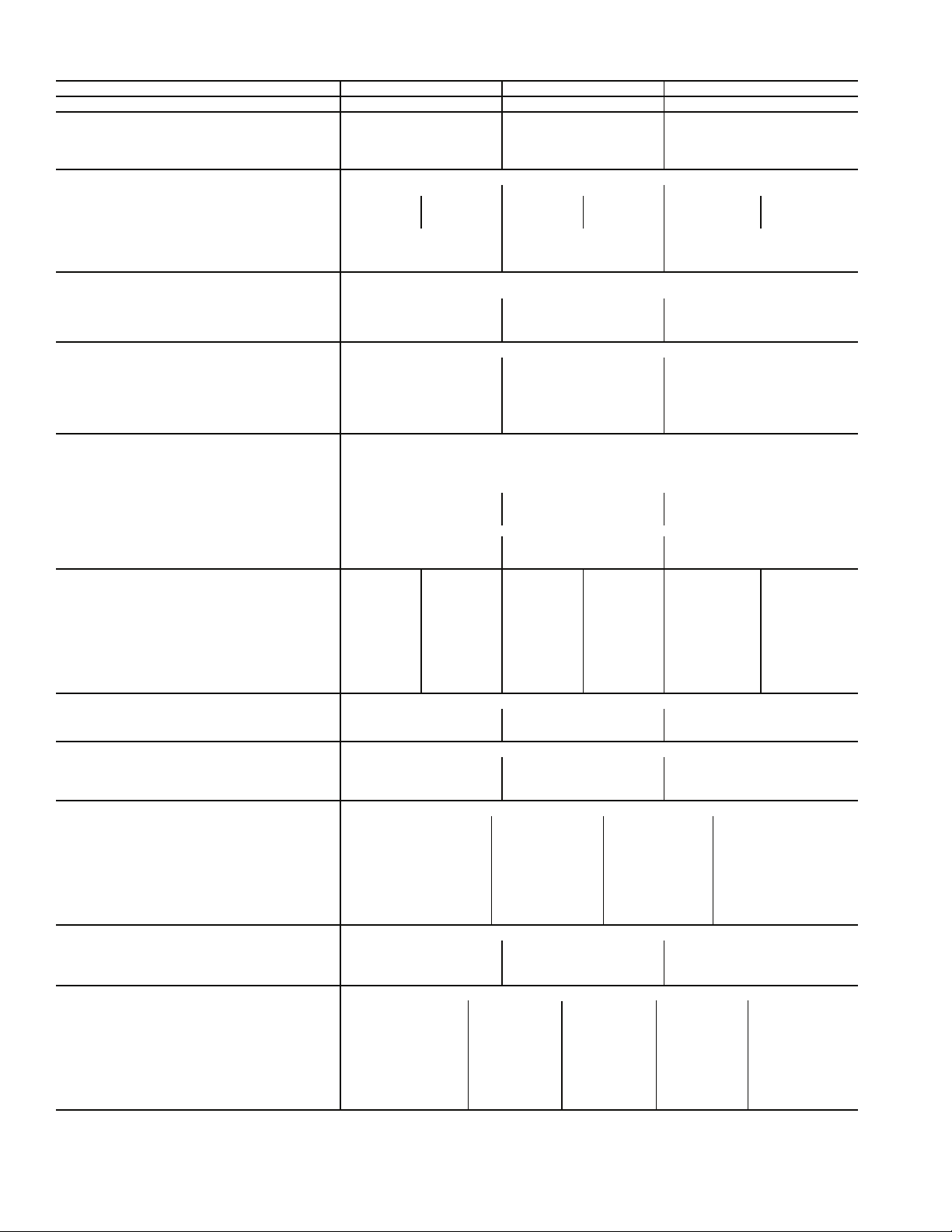
Table 1C — Physical Data (48ZG,ZN075-105)
BASE UNIT 48ZG,ZN075 48ZG,ZN090 48ZG,ZN105
NOMINAL CAPACITY (tons) 75 90 105
OPERATING WEIGHT (lb)
Base Unit without Economizer
Low Heat/High Heat 10,270/10,445 10,480/10,655 11,210/11,385
With Economizer
Low Heat/High Heat 10,800/10,975 11,010/11,185 11,740/11,915
COMPRESSOR Semi-Hermetic
Number 22 4
Circuit (No. Cyl) A (6) B (6) A (6) B (6) A1 (6), A2 (4) B1 (6), B2 (4)
Model 06E -275 -299 -299 -299 -275, -250 -275, -250
Oil Charge (pints) 19 19 19 19 19, 14 19, 14
Capacity Steps (%)
CV 43,100 50,100 50,100
VAV 14,29,43,51,66,86,100 17,33,50,67,83,100 20,30,40,50,60,60,70,80,80,90,100
Number of Refrigerant Circuits 22 2
REFRIGERANT R-22
Operating Charge (lb), Ckt 1/Ckt 2
Standard Evaporator Coil 70.5/64.5 64.0/64.0 68.0/68.0
Standard Evaporator with HGBP 73.5/64.5 67.0/64.0 71.0/68.0
Alternate High-Capacity Evaporator Coil 83.0/75.0 76.0/76.0 79.5/79.5
Alternate High-Capacity Evaporator with HGBP 86.0/75.0 79.0/76.0 82.5/79.5
CONDENSER COILS
Quantity 44 4
Rows...Fins/in.
Aluminum 3...17.0 3...17.0 3...17.0
Copper (Optional) 3...15.7 3...15.7 3...15.7
Fin Type Double Wavy Lanced, Sine-wave Lanced, Sine-wave
Tube Type Smooth Cross-Hatched Cross-Hatched
Total Face Area (sq ft) 108.4 108.4 108.4
EVAPORATOR COILS
Quantity 2
Total Face Area (sq ft) 61.5
Refrigerant Feed Device...No. per Circuit TXV...2
Standard Evaporator Coils
Rows...Fins/in. 4...17.0 4...17.0 4...17.0
Fin Type Double Wavy Lanced, Sine Wave Lanced, Sine Wave
Tub e Ty p e Smooth Cross Hatched Cross Hatched
Alternate, High-Capacity Evaporator Coils
Rows...Fins/in. 6...16 6...16 6...16
Fin Type Double Wavy Double Wavy Double Wavy
Tub e Ty p e Cross Hatched Cross Hatched Cross Hatched
HEATING SECTION Low Heat High Heat Low Heat High Heat Low Heat High Heat
Number of Heat Exchangers 2323 2 3
Input (MBtuh) 650 975 650 975 650 975
Output (MBtuh) 527 790 527 790 527 790
Temperature Rise Range (F) 10-40 20-50 10-40 20-50 10-40 20-50
Efficiency (%) 81 81 81 81 81 81
Burner Orifice Diameter
Quantity (in. ...drill no.) 14 (.1285...30) 21 (.1285...30) 14 (.1285...30) 21 (.1285...30) 14 (.1285...30) 21 (.1285...30)
Manifold Pressure (in. wg) 3.3 3.3 3.3 3.3 3.3 3.3
Line Pressure (in. wg) (Min...Max) 5.0...13.0 5.0...13.0 5.0...13.0 5.0...13.0 5.0...13.0 5.0...13.0
Number of Gas Valves 2323 2 3
CONDENSER FAN Propeller Type
Quantity...Diameter (in.) 5...30 6...30 6...30
Nominal Cfm 50,000 60,000 60,000
Motor Hp (ea)...rpm 1.0...1140 1.0...1140 1.0...1140
STANDARD SUPPLY FAN Forward Curved Centrifugal 36 x 30 in.
Nominal Cfm 24,500 29,750 35,000
Maximum Allowable Cfm 30,000 34,000 40,000
Maximum Allowable Rpm 670 670 670
Shaft Diameter at Pulley (in.) 1
STANDARD SUPPLY-FAN MOTOR AND DRIVE (Any motor available on any unit)
Motor Hp 30 40 50 60
Motor Frame Size S268T S324T S36T S364T
Efficiency at Full Load (%)
High Efficiency 92.4 93.0 93.0 93.6
Premium Efficiency 93.6 94.5 94.5 95.4
Fan Pulley Pitch Diameter (in.) 18.5 18.5 18.5 18.5
Motor Pulley Pitch Diameter (in.) 5.3 5.7 6.5 7.1
Resulting Fan Rpm 501 539 615 672
Belts Quantity...Type 3...5VX1320 4...5VX1320 4...5VX1320 4...5VX1320
Center Distance Range (in.) 47.88-45.01 47.64-44.76 47.42-44.52 47.42-44.52
ALTERNATE, AIRFOIL FAN Airfoil
Nominal Airflow (cfm) 24,500 29,750 35,000
Maximum Allowable Airflow (cfm) 30,000 34,000 40,000
Maximum Allowable Wheel Speed (rpm) 1846 1846 1846
Shaft Diameter at Pulley (in.) 2
ALTERNATE SUPPLY-FAN MOTOR AND DRIVE (Any motor available on any unit)
Motor Hp 30 40 50 60 75
Motor Frame Size S268T S324T S36T S364T 365T
Efficiency at Full Load (%)
High Efficiency 92.4 93.0 93.0 93.6 94.1
Premium Efficiency 93.6 94.5 94.5 95.4 95.4
Fan Pulley Pitch Diameter (in.) 9.7 10.2 8.9 8.9 10.8
Motor Pulley Pitch Diameter (in.) 7.5 8.7 8.1 8.7 11.1
Resulting Fan Rpm 1353 1493 1593 1711 1799
Belts Quantity...Type 2...5VX1150 2...5VX1180 3...5VX1150 3...5VX1150 3...5VX1230
Center Distance Range (in.) 42.96-45.82 42.96-45.57 42.96-45.57 42.45-45.35 42.45-45.35
1
/2 in. Tube Dia
11
/
16
11
/
16
3
/8-in. Tube Diameter
3
/8 in. Tube Dia
1
/2 in. Tube Dia
111/
16
211/
16
3
/8 in. Tube Dia
111/
16
211/
16
6
Page 7

Table 1C — Physical Data (48ZG,ZN075-105) (cont)
BASE UNIT 48ZG,ZN075 48ZG,ZN090 48ZG,ZN105
OPTIONAL POWER EXHAUST Centrifugal, 18 x 15 in. (Any motor available on any unit.)
Quantity...Motor Hp 2...5 2...7.5 2...10
Motor Frame Size 184T 213T 215T
Efficiency at Full Load (%)
High Efficiency 87.5 88.5 89.5
Premium Efficiency 89.5 91.7 91.7
Fan Pulley Pitch Diameter (in.) 10.6 10.6 10.6
Motor Pulley Pitch Diameter (in.) 4.5 5.0 5.6
Shaft Diameter at Pulley (in.) 1
Resulting Fan Rpm 740 820 920
Maximum Allowable Rpm 1000 1000 1000
FILTERS
Standard Efficiency Throwaway
(Standard)
Quantity...Size (in.) 12...20 x 20 x 2 12...20 x 20 x 2 12...20 x 20 x 2
30% and 65% Pleated (Optional) 12...20 x 25 x 2 12...20 x 25 x 2 12...20 x 25 x 2
Quantity...Size (in.) 12...20 x 20 x 2 12...20 x 20 x 2 12...20 x 20 x 2
OUTSIDE AIR SCREENS
Standard Hood (25%) Quantity...Size (in.)
OPTIONAL ECONOMIZER FILTER Aluminum Frame, Permanent
Quantity...Size (in.)
LEGEND
CV — Constant Volume
HGBP — Hot Gas Bypass
MBtuh— Btuh in Thousands
TXV — Thermostatic Expansion Valve
VAV — Va r ia b le A ir Vo lum e
7
/
16
17/
16
17/
16
12...20 x 25 x 2 12...20 x 25 x 2 12...20 x 25 x 2
4...25 x 16 x 1
2...20 x 16 x 1
12...16 x 25 x 1
2...16 x 20 x 1
4...25 x 16 x 1
2...20 x 16 x 1
12...16 x 25 x 1
2...16 x 20 x 1
4...25 x 16 x 1
2...20 x 16 x 1
12...16 x 25 x 1
2...16 x 20 x 1
7
Page 8
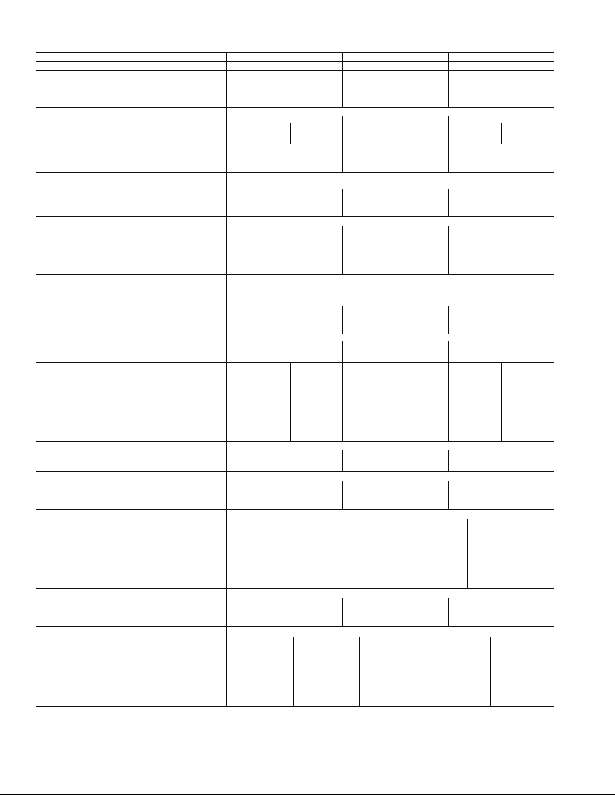
Table 1D — Physical Data (48Z6,Z8075-105)
BASE UNIT 48Z6,Z8075 48Z6,Z8090 48Z6,Z8105
NOMINAL CAPACITY (tons) 75 90 105
OPERATING WEIGHT (lb)
Base Unit without Economizer
Low Heat/High Heat 11,740/11,915 11,950/12,125 12,680/12,855
With Economizer
Low Heat/High Heat 12,270/12,445 12,480/12,655 13,210/13,385
COMPRESSOR Semi-Hermetic
Number 224
Circuit (No. Cyl) A (6) B (6) A (6) B (6) A1 (6), A2 (4) B1 (6), B2 (4)
Model 06E -275 -299 -299 -299 -275, -250 -275, -250
Oil Charge (pints) 19 19 19 19 19, 14 19, 14
Capacity Steps (%)
CV 43,100 50,100 50,100
VAV 14,29,43,51,66,71,86,100 17,33,50,67,83,100 20,30,40,50,60,70,80,90,100
Number of Refrigerant Circuits 222
REFRIGERANT R-22
Operating Charge (lb), Ckt 1/Ckt 2
Standard Evaporator Coil 70.5/64.5 64.0/64.0 68.0/68.0
Standard Evaporator with HGBP 73.5/64.5 67.0/64.0 71.0/68.0
Alternate High-Capacity Evaporator Coil 83.0/75.0 76.0/76.0 79.5/79.5
Alternate High-Capacity Evaporator with HGBP 86.0/75.0 79.0/76.0 82.5/79.5
CONDENSER COILS
Quantity 444
Rows...Fins/in.
Aluminum 3...17.0 3...17.0 3...17.0
Copper (Optional) 3...15.7 3...15.7 3...15.7
Fin Type Double Wavy Lanced, Sine-wave Lanced, Sine-wave
Tube Type Smooth Cross-Hatched Cross-Hatched
Total Face Area (sq ft) 108.4 108.4 108.4
EVAPORATOR COILS
Quantity 2
Total Face Area (sq ft) 61.5
Refrigerant Feed Device...No. per Circuit TXV...2
Standard Evaporator Coils
Rows...Fins/in. 4...17.0 4...17.0 4...17.0
Fin Type Double Wavy Lanced, Sine Wave Lanced, Sine Wave
Tub e Ty p e Smooth Cross Hatched Cross Hatched
Alternate, High-Capacity Evaporator Coils
Rows...Fins/in. 6...16 6...16 6...16
Fin Type Double Wavy Double Wavy Double Wavy
Tub e Ty p e Cross Hatched Cross Hatched Cross Hatched
HEATING SECTION Low Heat High Heat Low Heat High Heat Low Heat High Heat
Number of Heat Exchangers 2 32323
Input (MBtuh) 650 975 650 975 650 975
Output (MBtuh) 527 790 527 790 527 790
Temperature Rise Range (F) 10-40 20-50 10-40 20-50 10-40 20-50
Efficiency (%) 81 81 81 81 81 81
Burner Orifice Diameter
Quantity (in. ...drill no.) 14 (.1285...30) 21 (.1285...30) 14 (.1285...30) 21 (.1285...30) 14 (.1285...30) 21 (.1285...30)
Manifold Pressure (in. wg) 3.3 3.3 3.3 3.3 3.3 3.3
Line Pressure (in. wg) (Min...Max) 5.0...13.0 5.0...13.0 5.0...13.0 5.0...13.0 5.0...13.0 5.0...13.0
Number of Gas Valves 2 32323
CONDENSER FAN Propeller Type
Quantity...Diameter (in.) 5...30 6...30 6...30
Nominal Cfm 50,000 60,000 60,000
Motor Hp (ea)...rpm 1.0...1140 1.0...1140 1.0...1140
STANDARD SUPPLY FAN Forward Curved Centrifugal 36 x 30 in.
Nominal Cfm 24,500 29,750 35,000
Maximum Allowable Cfm 30,000 34,000 40,000
Maximum Allowable Rpm 670 670 670
Shaft Diameter at Pulley (in.) 1
STANDARD SUPPLY-FAN MOTOR AND DRIVE (Any motor available on any unit.)
Motor Hp 30 40 50 60
Motor Frame Size S268T S324T S36T S364T
Efficiency at Full Load (%)
High Efficiency 92.4 93.0 93.0 93.6
Premium Efficiency 93.6 94.5 94.5 95.4
Fan Pulley Pitch Diameter (in.) 18.5 18.5 18.5 18.5
Motor Pulley Pitch Diameter (in.) 5.3 5.7 6.5 7.1
Resulting Fan Rpm 501 539 615 672
Belts Quantity...Type 3...5VX1320 4...5VX1320 4...5VX1320 4...5VX1320
Center Distance Range (in.) 47.88-45.01 47.64-44.76 47.42-44.52 47.42-44.52
ALTERNATE, AIRFOIL FAN Airfoil
Nominal Airflow (cfm) 24,500 29,750 35,000
Maximum Allowable Airflow (cfm) 30,000 34,000 40,000
Maximum Allowable Wheel Speed (rpm) 1846 1846 1846
Shaft Diameter at Pulley (in.) 2
ALTERNATE SUPPLY-FAN MOTOR AND DRIVE (Any motor available on any unit.)
Motor Hp
Motor Frame Size
Efficiency at Full Load (%)
High Efficiency
Premium Efficiency
Fan Pulley Pitch Diameter (in.)
Motor Pulley Pitch Diameter (in.)
Resulting Fan Rpm
Belts Quantity...Type
Center Distance Range (in.)
1
/2 in. Tube Dia
11
/
16
11
/
16
30 40 50 60 75
S268T S324T S36T S364T 365T
92.4 93.0 93.0 93.6 94.1
93.6 94.5 94.5 95.4 95.4
9.7 10.2 8.9 8.9 10.8
7.5 8.7 8.1 8.7 11.1
1353 1493 1593 1711 1799
2...5VX1150 2...5VX1180 3...5VX1150 3...5VX1150 3...5VX1230
42.96-45.82 42.69-45.57 42.69-45.57 42.45-45.35 42.45-45.35
3
/8-in. Tube Diameter
3
/8 in. Tube Dia
1
/2 in. Tube Dia
111/
16
211/
16
3
/8 in. Tube Dia
111/
16
211/
16
8
Page 9
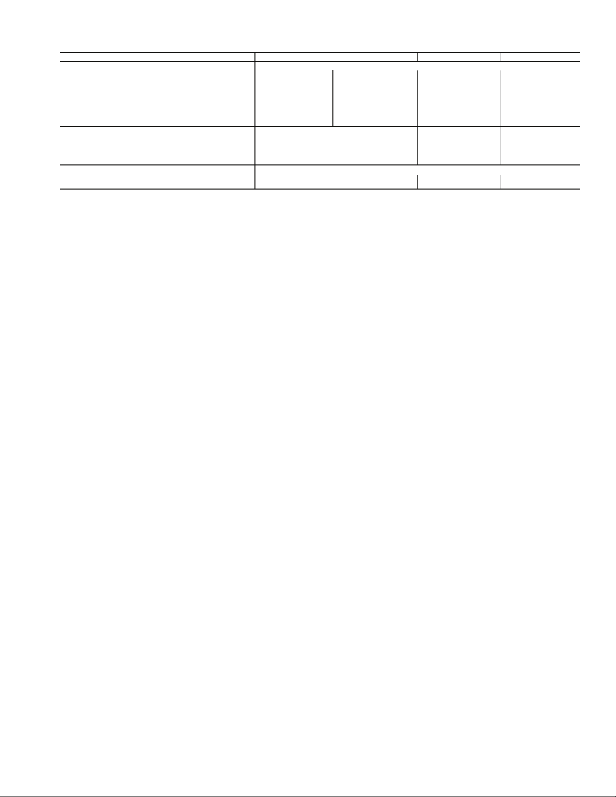
Table 1D — Physical Data (48Z6,Z8075-105) (cont)
BASE UNIT 48Z6,Z8075 48Z6,Z8090 48Z6,Z8105
RETURN/EXHAUST FAN Plenum Fan, 47.13 in. (Any motor available on any unit.)
Quantity...Motor Hp 1...20 1...25 1...30 1...40
Motor Frame Size 256T 284T 286T 324T
Efficiency at Full Load (%) High/Premium 91/93.6 91.7/93.6 92.4/93.6 93/93.8
Fan Pulley Pitch Diameter (in.) 8.5 9.8 8.5 8.5
Motor Pulley Pitch Diameter (in.) 5.3 6.7 6.1 6.7
Shaft Diameter at Pulley (in.) 2
Resulting Fan Rpm 1104 1209 1271 1396
Maximum Allowable Rpm 1447 1447 1447 1447
FILTERS
Standard Efficiency Throwaway (Standard) 12...20 x 25 x 2 12...20 x 25 x 2 12...20 x 25 x 2
Quantity...Size (in.) 12...20 x 20 x 2 12...20 x 20 x 2 12...20 x 20 x 2
30% and 65% Pleated (Optional) 12...20 x 25 x 2 12...20 x 25 x 2 12...20 x 25 x 2
Quantity...Size (in.) 12...20 x 20 x 2 12...20 x 20 x 2 12...20 x 20 x 2
OPTIONAL ECONOMIZER FILTER Aluminum Frame, Permanent
Quantity...Size (in.)
LEGEND
CV — Constant Volume
HGBP — Hot Gas Bypass
MBtuh— Btuh in Thousands
TXV — Thermostatic Expansion Valve
VAV — Va r ia b le A ir Vo lum e
15
/
16
12...16 x 25 x 1
2...16 x 20 x 1
215/
16
215/
16
12...16 x 25 x 1
2...16 x 20 x 1
215/
12...16 x 25 x 1
2...16 x 20 x 1
16
9
Page 10
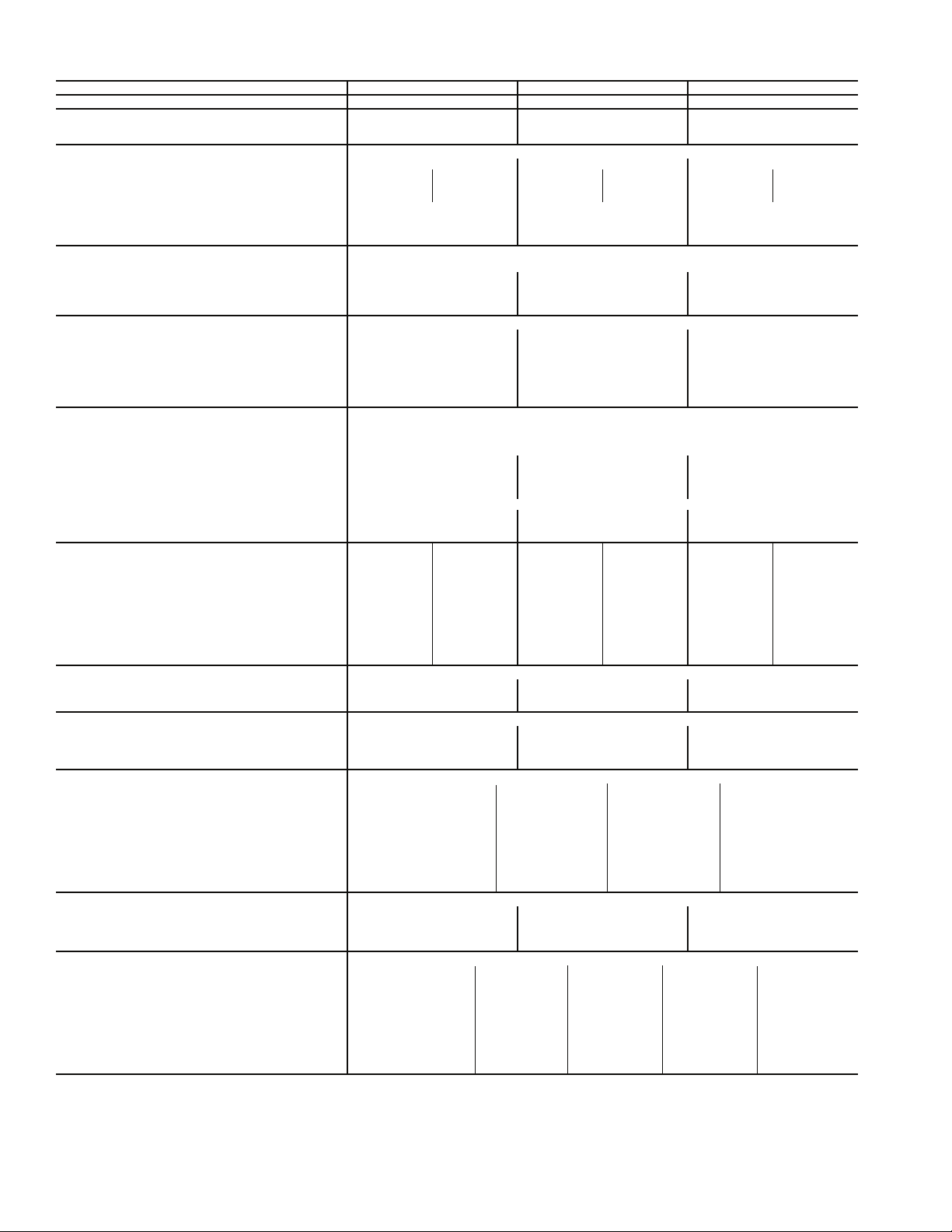
Table 1E — Physical Data (48ZT,ZW075-105)
BASE UNIT 48ZT,ZW075 48ZT,ZW090 48ZT,ZW105
NOMINAL CAPACITY (tons) 75 80 100
OPERATING WEIGHT (lb)
Base Unit without Economizer
Low Heat/High Heat 13,205/13,380 13,415/13,590 14,145/14,320
COMPRESSOR Semi-Hermetic
Number 224
Circuit (No. Cyl) A (6) B (6) A (6) B (6) A1 (6), A2 (4) B1 (6), B2 (4)
Model 06E -275 -299 -299 -299 -275, -250 -275, -250
Oil Charge (pints) 19 19 19 19 19, 14 19, 14
Capacity Steps (%)
CV 43,100 50,100 50,100
VAV 14,29,43,51,66,71,86,100 17,33,50,67,83,100 20,30,40,50,60,70,80,90,100
Number of Refrigerant Circuits 222
REFRIGERANT
Operating Charge (lb), Ckt 1/Ckt 2
Standard Evaporator Coil 70.5/64.5 64.0/64.0 68.0/68.0
Standard Evaporator with HGBP 73.5/64.5 67.0/64.0 71.0/68.0
Alternate High-Capacity Evaporator Coil 83.0/75.0 76.0/76.0 79.5/79.5
Alternate High-Capacity Evaporator with HGBP 86.0/75.0 79.0/76.0 82.5/79.5
CONDENSER COILS
Quantity 444
Rows...Fins/in.
Aluminum 3...17.0 3...17.0 3...17.0
Copper (Optional) 3...15.7 3...15.7 3...15.7
Fin Type Double Wavy Lanced, Sine-wave Lanced, Sine-wave
Tube Type Smooth Cross-Hatched Cross-Hatched
Total Face Area (sq ft) 108.4 108.4 108.4
EVAPORATOR COILS
Quantity 2
Total Face Area (sq ft) 61.5
Refrigerant Feed Device...No. per Circuit TXV...2
Standard Evaporator Coils
Rows...Fins/in. 4...17.0 4...17.0 4...17.0
Fin Type Double Wavy Lanced, Sine Wave Lanced, Sine Wave
Tube Type Smooth Cross Hatched Cross Hatched
Alternate, High-Capacity Evaporator Coils
Rows...Fins/in. 6...16 6...16 6...16
Fin Type Double Wavy Double Wavy Double Wavy
Tube Type Cross Hatched Cross Hatched Cross Hatched
HEATING SECTION Low Heat High Heat Low Heat High Heat Low Heat High Heat
Number of Heat Exchangers 232323
Input (MBtuh) 650 975 650 975 650 975
Output (MBtuh) 527 790 527 790 527 790
Temperature Rise Range (F) 10-40 20-50 10-40 20-50 10-40 20-50
Efficiency (%) 81 81 81 81 81 81
Burner Orifice Diameter
Quantity (in. ...drill no.) 14 (.1285...30) 21 (.1285...30) 14 (.1285...30) 21 (.1285...30) 14 (.1285...30) 21 (.1285...30)
Manifold Pressure (in. wg) 3.33.33.33.33.33.3
Line Pressure (in. wg) (Min...Max) 5.0...13.0 5.0...13.0 5.0...13.0 5.0...13.0 5.0...13.0 5.0...13.0
Number of Gas Valves 232323
CONDENSER FAN Propeller Type
Quantity...Diameter (in.) 5...30 6...30 6...30
Nominal Cfm 50,000 60,000 60,000
Motor Hp (ea)...rpm 1.0...1140 1.0...1140 1.0...1140
STANDARD SUPPLY FAN Forward Curved Centrifugal 36 x 30 in.
Nominal Cfm 24,500 29,750 35,000
Maximum Allowable Cfm 30,000 34,000 40,000
Maximum Allowable Rpm 670 670 670
Shaft Diameter at Pulley (in.) 1
STANDARD SUPPLY-FAN MOTOR AND DRIVE (Any motor available on any unit)
Motor Hp 30 40 50 60
Motor Frame Size S268T S324T S36T S364T
Efficiency at Full Load (%)
High Efficiency 92.4 93.0 93.0 93.6
Premium Efficiency 93.6 94.5 94.5 95.4
Fan Pulley Pitch Diameter (in.) 18.5 18.5 18.5 18.5
Motor Pulley Pitch Diameter (in.) 5.3 5.7 6.5 7.1
Resulting Fan Rpm 501 539 615 672
Belts Quantity...Type 3...5VX1320 4...5VX1320 4...5VX1320 4...5VX1320
Center Distance Range (in.) 47.88-45.01 47.64-44.76 47.42-44.52 47.42-44.52
ALTERNATE, AIRFOIL FAN Airfoil
Nominal Airflow (cfm) 24,500 29,750 35,000
Maximum Allowable Airflow (cfm) 30,000 34,000 40,000
Maximum Allowable Wheel Speed (rpm) 1846 1846 1846
Shaft Diameter at Pulley (in.) 2
ALTERNATE SUPPLY-FAN MOTOR AND DRIVE (Any motor available on any unit)
Motor Hp 30 40 50 60 75
Motor Frame Size S268T S324T S36T S364T 365T
Efficiency at Full Load (%)
High Efficiency 92.4 93.0 93.0 93.6 94.1
Premium Efficiency 93.6 94.5 94.5 95.4 95.4
Fan Pulley Pitch Diameter (in.) 9.7 10.2 8.9 8.9 10.8
Motor Pulley Pitch Diameter (in.) 7.5 8.7 8.1 8.7 11.1
Resulting Fan Rpm 1353 1493 1593 1711 1799
Belts Quantity...Type 2...5VX1150 2...5VX1180 3...5VX1150 3...5VX1150 3...5VX1230
Center Distance Range (in.) 42.96-45.82 42.96-45.57 42.96-45.57 42.45-45.35 42.45-45.35
1
/2 in. Tube Dia
11
/
16
11
/
16
R-22
3
/8-in. Tube Diameter
3
/8 in. Tube Dia
1
/2 in. Tube Dia
111/
16
211/
16
3
/8 in. Tube Dia
111/
16
211/
16
10
Page 11
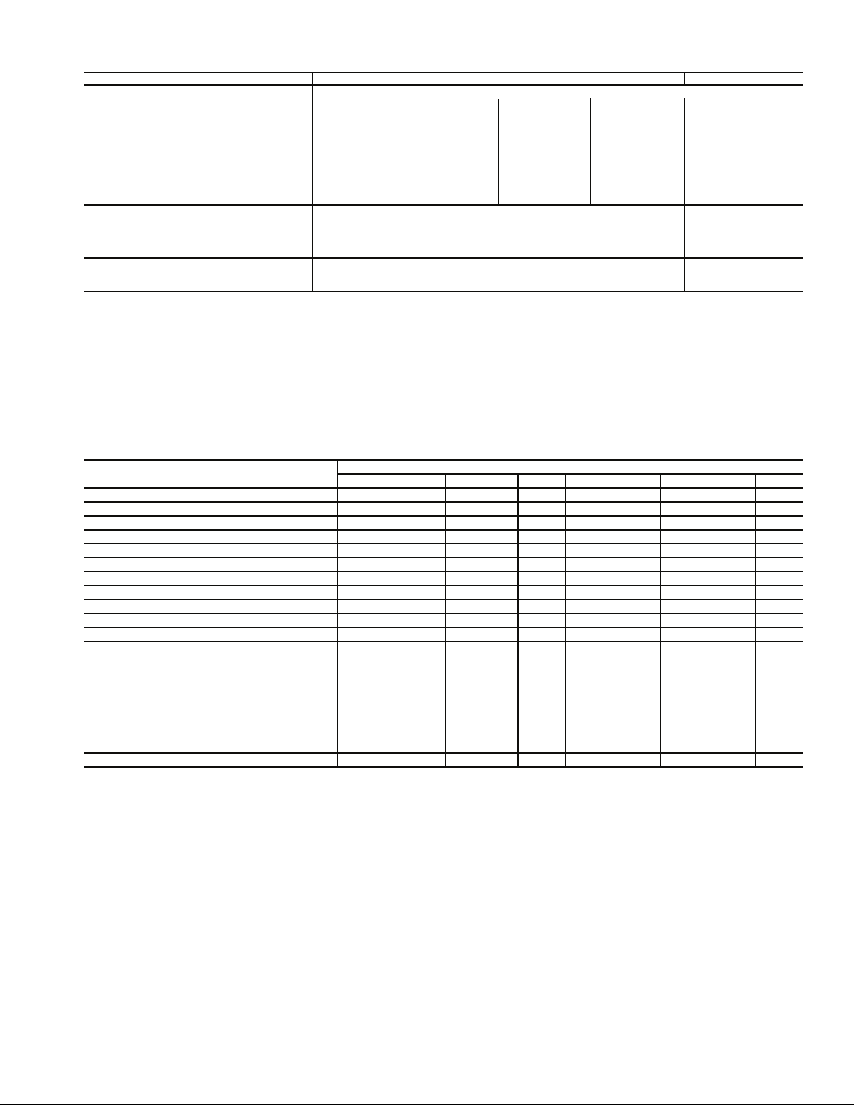
Table 1E — Physical Data (48ZT,ZW075-105) (cont)
BASE UNIT 48ZT,ZW075 48ZT,ZW090 48ZT,ZW105
POWER EXHAUST Centrifugal, 22 x 20 in., 1
Tot a l Hp 20 30 40 50 60
Quantity...Motor Hp 2...10 2...15 2...20 2...25 2...30
Motor Frame Size S215T D254T S256T S284T S286T
Efficiency at Full Load (%)
High Efficiency 89.5 91 91 91.7 92.4
Premium Efficiency 91.7 93 93.6 93.6 93.6
Fan Sheave Pitch Diameter (in.) 12.4 12.4 11.1 11.1 11.1
Motor Sheave Pitch Diameter (in.) 4.8 5.8 5.9 6.5 6.9
Resulting Fan Rpm 714 841 928 1020 1094
Maximum Allowable Rpm 1175 1175 1175 1175 1175
Belts — Quantity...Type 2...BX93 2...BX93 2...5VX950 2...5VX950 2...5VX950
FILTERS
Standard Efficiency Throwaway (Standard) 12...20 x 25 x 2 12...20 x 25 x 2 12...20 x 25 x 2
Quantity...Size (in.) 12...20 x 20 x 2 12...20 x 20 x 2 12...20 x 20 x 2
30% and 65% Pleated (Optional) 12...20 x 25 x 2 12...20 x 25 x 2 12...20 x 25 x 2
Quantity...Size (in.) 12...20 x 20 x 2 12...20 x 20 x 2 12...20 x 20 x 2
OUTSIDE AIR SCREENS
Standard Hood (25%) Quantity...Size (in.)
LEGEND
CV — Constant Volume
HGBP — Hot Gas Bypass
MBtuh— Btuh in Thousands
TXV — Thermostatic Expansion Valve
VAV — Va r ia b le A ir Vo lum e
8...25 x 16 x 1
2...20 x 16 x 1
11
/16 in. shaft diameter (Any motor available on any unit)
8...25 x 16 x 1
2...20 x 16 x 1
8...25 x 16 x 1
2...20 x 16 x 1
Table 2 — Operating Weights of Options and Accessories (lb)
OPTION OR ACCESSORY
Roof Curb 450 480 515 515 515 560 560 560
Condenser Section Roof Curb — — 540 540 625 625 625 625
Economizer* 300 300 530 530 530 530 530 530
Power Exhaust* 600 600 710 710 710 710 710 710
Barometric Relief 200 200 200 200 200 200 200 200
Return Exhaust Fan* — — — — — 1470 1470 1470
High-Efficiency Filters 20 20 20 20 20 — — —
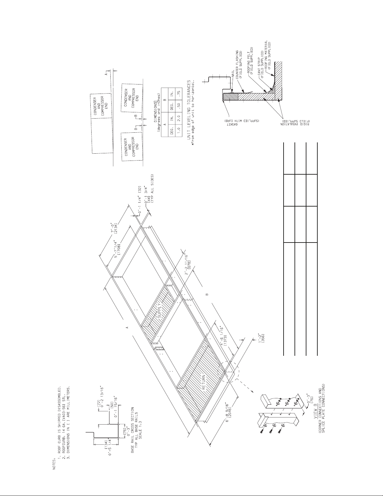
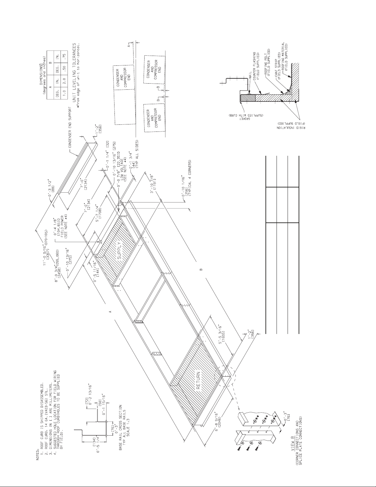
Bag Filters 35 35 40 40 40 — — —
Hail Guard 120 150 145 145 210 210 210 210
Copper Condenser Coil Fins 180 235 235 235 420 420 420 420
Inlet Guide Vanes 95 95 115 115 115 115 115 115
Variable Frequency Drive
7.5 hp
10 hp
15 hp
20 hp
25 hp
30 hp
40 hp
50 hp
60 hp
75 hp
High-Capacity Evaporator Coil — 300 300 300 300 300 300 300
030,035 040,050 055 060 070 075 090 105
65
65
110
111
190
—
—
—
—
—
65
65
110
111
190
190
—
—
—
—
UNIT SIZE
—
—
110
111
190
190
190
—
—
—
—
—
110
111
190
190
190
—
—
—
—
—
110
111
190
190
190
—
—
—
—
—
—
—
—
152
155
263
266
266
—
—
—
—
—
152
155
263
266
266
*Includes hood.
—
—
—
—
—
152
155
263
266
266
11
Page 12
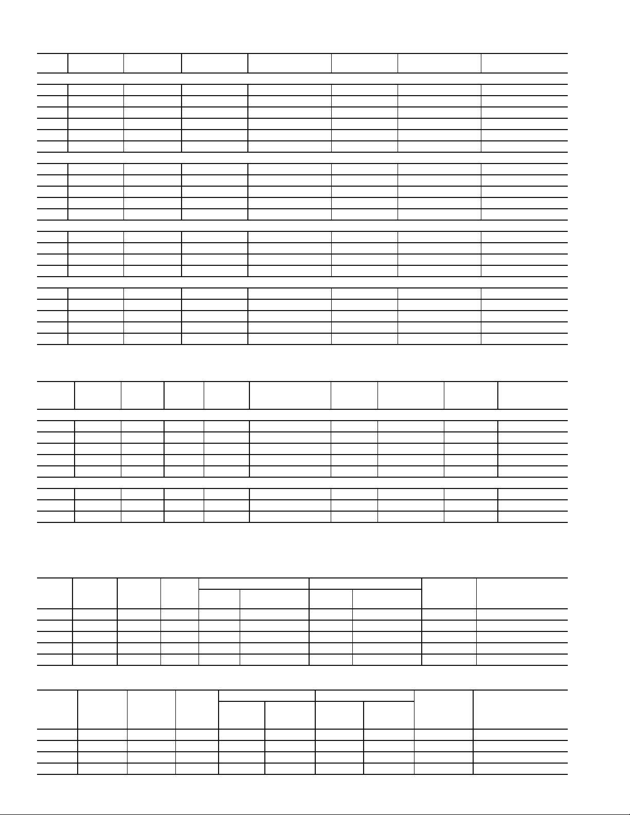
Table 3 — Supply Fan Drive Data
HP
SHAFT
DIA (in.)
SPEED
(rpm)
MOTOR
SHEAVE
MOTOR
PITCH DIA (in.)
WHEEL
SHEAVE
WHEEL
PITCH DIA (in.).
QUANTITY
...BELT
Sizes 030-050
7.5 1
10 1
15 1
20 1
25 1
30* 1
3
/
8
3
/
8
5
/
8
5
/
8
7
/
8
7
/
8
438 2BK36 3.4 2B5V136 13.7 2...BX60
549 2B5V42 4.3 2B5V136 13.7 2...5VX630
626 2B5V48 4.9 2B5V136 13.7 2...5VX630
703 2B5V54 5.5 2B5V136 13.7 2...5VX630
830 2B5V64 6.5 2B5V136 13.7 2...5VX650
910 3B5V64 6.5 3B5V124 12.5 3...5VX630
Sizes 055-070
15 1
20 1
25 1
30 1
40 2
5
/
8
5
/
8
7
/
8
7
/
8
1
/
8
575 2B5V44 4.5 2B5V136 13.7 2...5VX1230
651 2B5V50 5.1 2B5V136 13.7 2...5VX1230
703 2B5V54 5.5 2B5V136 13.7 2...5VX1230
711 2B5V62 6.3 2B5V154 15.5 2...5VX1230
740 3B5V66 6.7 3B5V160 16.1 3...5VX1250
Sizes 075-105 (Forward Curved Fan)
30 1
40 2
50 2
60 2
7
/
8
1
/
8
1
/
8
3
/
8
501 3B5V52 5.33 B5V184 18.5 3...5VX1320
539 4B5V56 5.74 B5V184 18.5 4...5VX1320
615 4B5V64 6.54 B5V184 18.5 4...5VX1320
672 4B5V70 7.14 B5V184 18.5 4...5VX1320
Sizes 075-105 (Airfoil Fan)
30 1
40 2
50 2
60 2
75 2
7
/
8
1
/
8
1
/
8
3
/
8
3
/
8
1353 2B5V74 7.5 2Q5V97 9.7 2...5VX1150
1493 2B5V86 8.7 2Q5V103 10.2 2...5VX1180
1593 3B5V80 8.1 3R5V90 8.9 3...5VX1150
1711 3B5V86 8.7 3R5V90 8.9 3...5VX1150
1799 3B5V110 11.1 3R5V109 10.8 3...5VX1230
*Sizes 040,050 only. NOTE: Part numbers are Browning Manufacturing Corp. reference.
Table 4 — Power Exhaust Fan Drive Data
TOTALHPMOTOR
QTY...HP
MOTOR
SHAFT
DIA (in.)
FAN
SPEED
RPM
MOTOR
SHEAVE
P/N
MOTOR SHEAVE
PITCH
DIA (in.)
FAN
SHEAVE
P/N
FAN SHEAVE
PITCH
DIA (in.)
BELTS
QTY...P/N
CENTER DIST
Sizes 030-050
6* 2...3
6† 2...3 1
10** 2...5 1
15** 2...7.5 1
20** 2...10 1
7
/
8
1
/
8
1
/
8
3
/
8
3
/
8
656 1VL44 4.1 BK115 11 1...BX71 23.62-26.50
656 1VP44L 4.1 BK115 11 1...BX71 23.62-26.50
785 1VP50L 4.7 BK110 10.4 1...BX71 23.62-26.50
882 1VP65 6.0 BK130 12 1...BX77 23.62-26.50
1000 1VP75 7.0 BK130 12 1...BX79 23.62-26.50
Sizes 055-105
1
10 2...5 1
15 2...7.5 1
20 2...10 1
*High-Efficiency Motor Option.
†Premium-Efficiency Motor Option.
**Applies to both motor options.
/
8
3
/
8
3
/
8
740 2P3V45 4.5 2Q3V106 10.6 2...3VX800 26.8-28.5
820 2P3V50 5.0 2Q3V106 10.6 2...3VX800 26.8-28.5
920 2P3V56 5.6 2Q3V106 10.6 2...3VX800 26.8-28.5
NOTE: Part numbers are Browning Manufacturing Corp. reference.
Table 5 — High-Capacity Power Exhaust Fan Drive Data (48ZT,ZW Units)
TOTALHPMOTOR
QTY...HP
MOTOR
SHAFT
DIA. (in.)
SPEED
RPM
20 2...10 1.375 714 2B5V48 4.8 2B5V124 12.4 2...BX93 32.8 to 36.7
30 2...15 1.625 841 2B5V58 5.8 2B5V124 12.4 2...BX93 32.6 to 36.5
40 2...20 1.625 928 2B5V58 5.9 2B5V110 11.1 2...5VX950 32.6 to 36.5
50 2...25 1.875 1020 2B5V64 6.5 2B5V110 11.1 2...5VX950 32.5 to 36.3
60 2...30 1.875 1094 2B5V68 6.9 2B5V110 11.1 2...5VX950 32.5 to 36.3
MOTOR SHEAVE BLOWER SHEAVE
Part
Number
Pitch Diameter
(in.)
Part
Number
Pitch Diameter
(in.)
QTY...BELT
CENTER DISTANCE
RANGE (in.)
Table 6 — Return/Exhaust Fan Drive Data (48Z6,Z8 Units)
RANGE (in.)
TOTALHPMOTOR
QTY...HP
MOTOR
SHAFT
DIA. (in.)
SPEED
RPM
MOTOR SHEAVE BLOWER SHEAVE
Part
Number
Pitch
Diameter
(in.)
Part
Number
Diameter
Pitch
(in.)
QTY...BELT
CENTER DISTANCE
RANGE (in.)
20 1...20 1.625 1104 3B5V52 5.3 3R5V85 8.5 3...5VX1000 38.1 to 41.0
25 1...25 1.875 1209 3B5V66 6.7 3R5V97 9.8 3...5VX1060 38.9 to 41.8
30 1...30 1.875 1271 3B5V60 6.1 3R5V85 8.5 3...5VX1030 38.9 to 41.8
40 1...40 2.125 1396 3B5V66 6.7 3R5V85 8.5 3...5VX1060 39.9 to 42.8
12
Page 13
*
″
″
″
″
16
8
8
16
/
/
/
/
5
7
5
11
16′-0
18′-1
27′-9
040,050
25′-8
UNIT SIZE
″
″
″
″
16
4
16
16
/
/
/
/
1
1
7
11
23′-9
21′-8
030,035
UNIT SIZE
15′-4
13′-3
A
B
A
B
UNIT TYPE DIMENSION
WITH GAS HEAT
VERTICAL SUPPLY AND RETURN
VERTICAL SUPPLY AND RETURN WITH
Fig. 1 — Roof Curb; Sizes 030-050
GAS HEAT AND EXTENDED CHASSIS
13
Page 14
*
″
″
″
″
8
8
16
16
/
/
/
/
7
3
3
11
055-105
UNIT SIZE
24′-11
29′-10
27′-9
22′-10
A
B
A
B
UNIT TYPE DIMENSION
WITH GAS HEAT
VERTICAL SUPPLY AND RETURN
VERTICAL SUPPLY AND RETURN WITH
GAS HEAT AND EXTENDED CHASSIS
Fig. 2 — Roof Curb; Sizes 055-070 and Sizes 075-105 without High-Capacity Power Exhaust
14
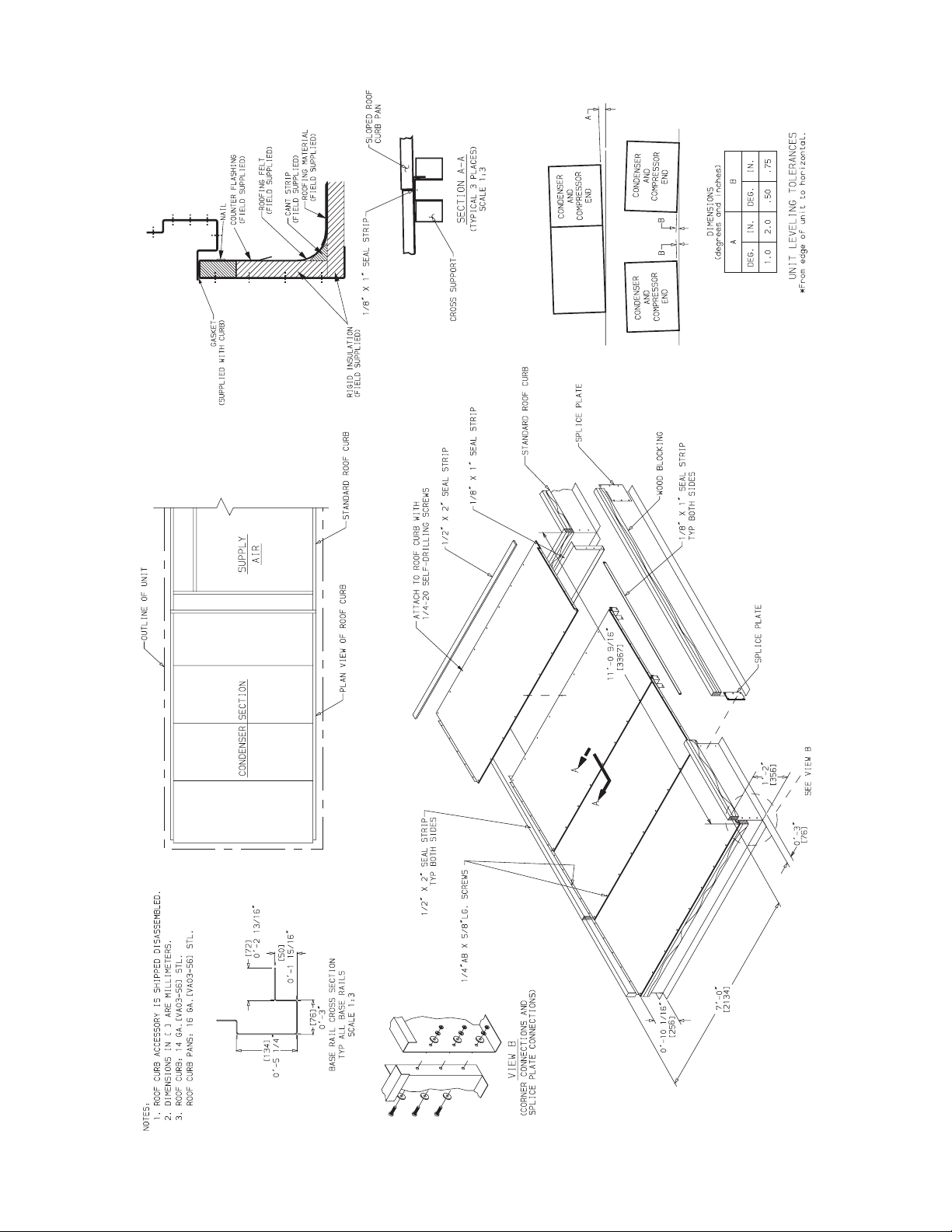
Page 15
15
Fig. 3 — Roof Curb; Sizes 075-105 with High-Capacity Power Exhaust
Page 16
*
16
Fig. 4 — Condenser Section Roof Curb (Size 055 and 060 Only)
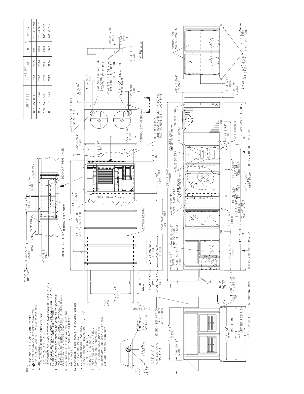
Page 17
*
17
Fig. 5 — Condenser Section Roof Curb (Size 070-105 Only)
Page 18
"X"
A
A
CONDENSER
END SUPPORT
4
1
4 REF.
9 3/4"
2
3
"X"-
NO GASKET
DETAIL A-A
Fig. 6 — Gasket Location on Roof Curb (48ZG,ZN055-105 and 48Z6,Z8075-105 Units)
5
5
Fig. 7 — Gasket Location — Condenser Section Roof Curb (Size 055-105 Units)
18
Page 19
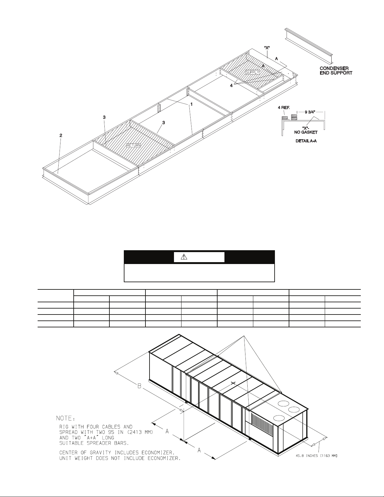
Fig. 8 — Gasket Location on Roof Curb (48ZT,ZW075-105 Units)
CAUTION
1. ALL PANELS MUST BE IN PLACE WHEN RIGGING.
2. DO NOT ATTEMPT TO FORK THESE UNITS.
NOTICE TO RIGGERS
UNIT
48Z030 5770 2623 83.23 2114 176.14 4474 300 136
48Z035 5895 2679 83.23 2114 177.99 4521 300 136
48Z040 6670 3032 92.64 2353 205.87 5229 300 136
48Z050 6710 3050 92.64 2353 207.01 5258 300 136
WEIGHT A B ECONOMIZER
lb kg in. mm in. mm lb kg
Fig. 9 — Rigging Label — Size 030-050 Units (Standard Chassis)
19
Page 20
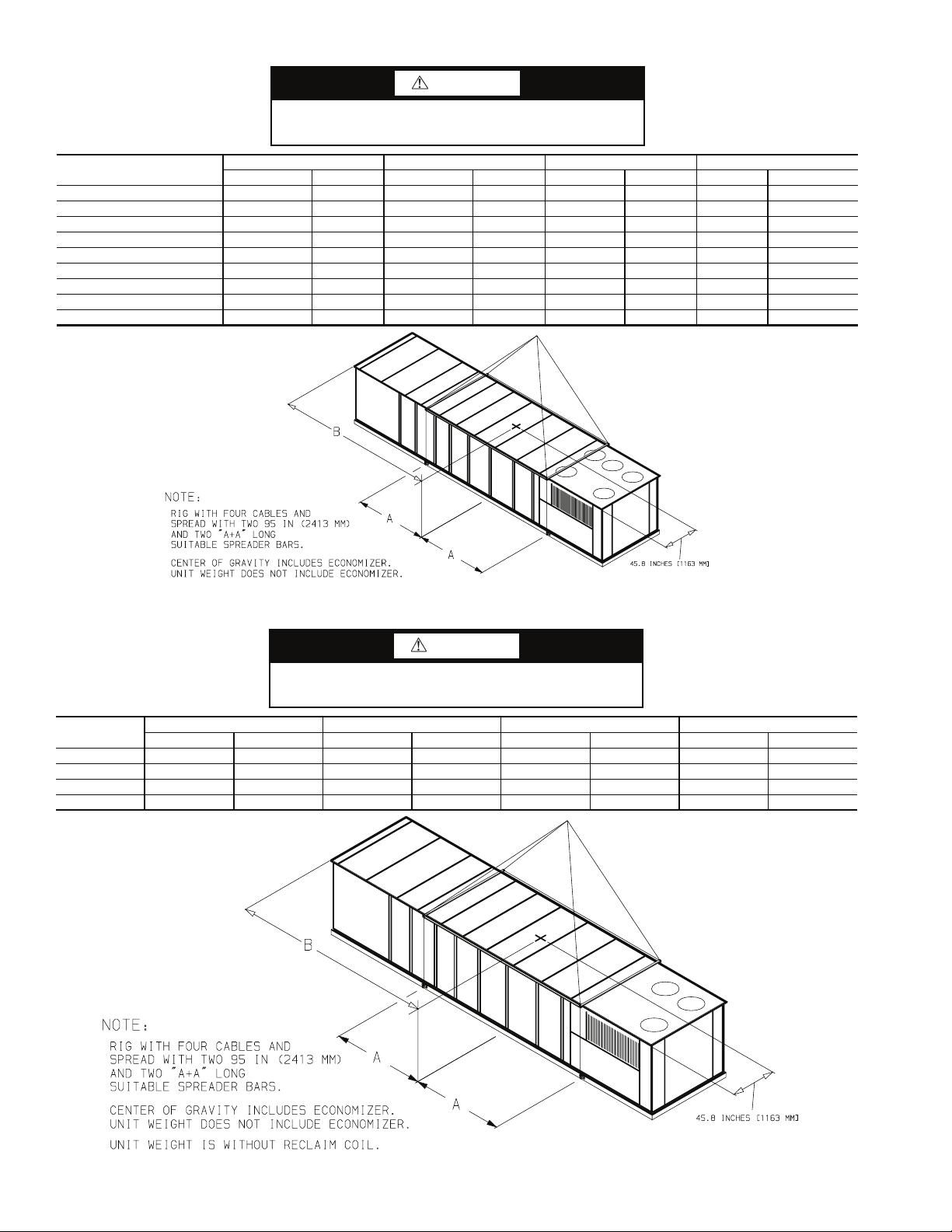
CAUTION
1. ALL PANELS MUST BE IN PLACE WHEN RIGGING.
2. DO NOT ATTEMPT TO FORK THESE UNITS.
NOTICE TO RIGGERS
UNIT
48Z055 8,820 4009 128.75 3270 235.0 5969 530 240.9
48Z060 9,120 4145 128.75 3270 235.0 5969 530 240.9
48Z070 9,550 4341 112.50 2858 252.0 6401 530 240.9
48ZG,ZN075 10,445 4738 127.80 3247 260.6 6618 530 240.9
48ZG,ZN090 10,655 4833 127.80 3247 262.4 6666 530 240.9
48ZG,ZN105 11,385 5164 127.80 3247 271.0 6883 530 240.9
48Z6,Z8075 11,915 5405 127.80 3247 260.6 6618 530 240.9
48Z6,Z8090 12,125 5500 127.80 3247 262.4 6666 530 240.9
48Z6,Z8105 12,855 5831 127.80 3247 271.0 6883 530 240.9
WEIGHT A B ECONOMIZER
lb kg in. mm in. mm lb kg
Fig. 10 — Rigging Label — Size 055-105 Units (Standard Chassis)
CAUTION
1. ALL PANELS MUST BE IN PLACE WHEN RIGGING.
2. DO NOT ATTEMPT TO FORK THESE UNITS.
UNIT
48Z030 6270 2844 95.83 2434 192.56 4891 300 136
48Z035 6395 2900 95.83 2434 194.72 4946 300 136
48Z040 7170 3252 105.24 2673 222.44 5650 300 136
48Z050 7210 3270 105.24 2673 223.50 5677 300 136
WEIGHT A B ECONOMIZER
lb kg in. mm in. mm lb kg
NOTICE TO RIGGERS
Fig. 11 — Rigging Label — Size 030-050 Units (Extended Chassis)
20
Page 21
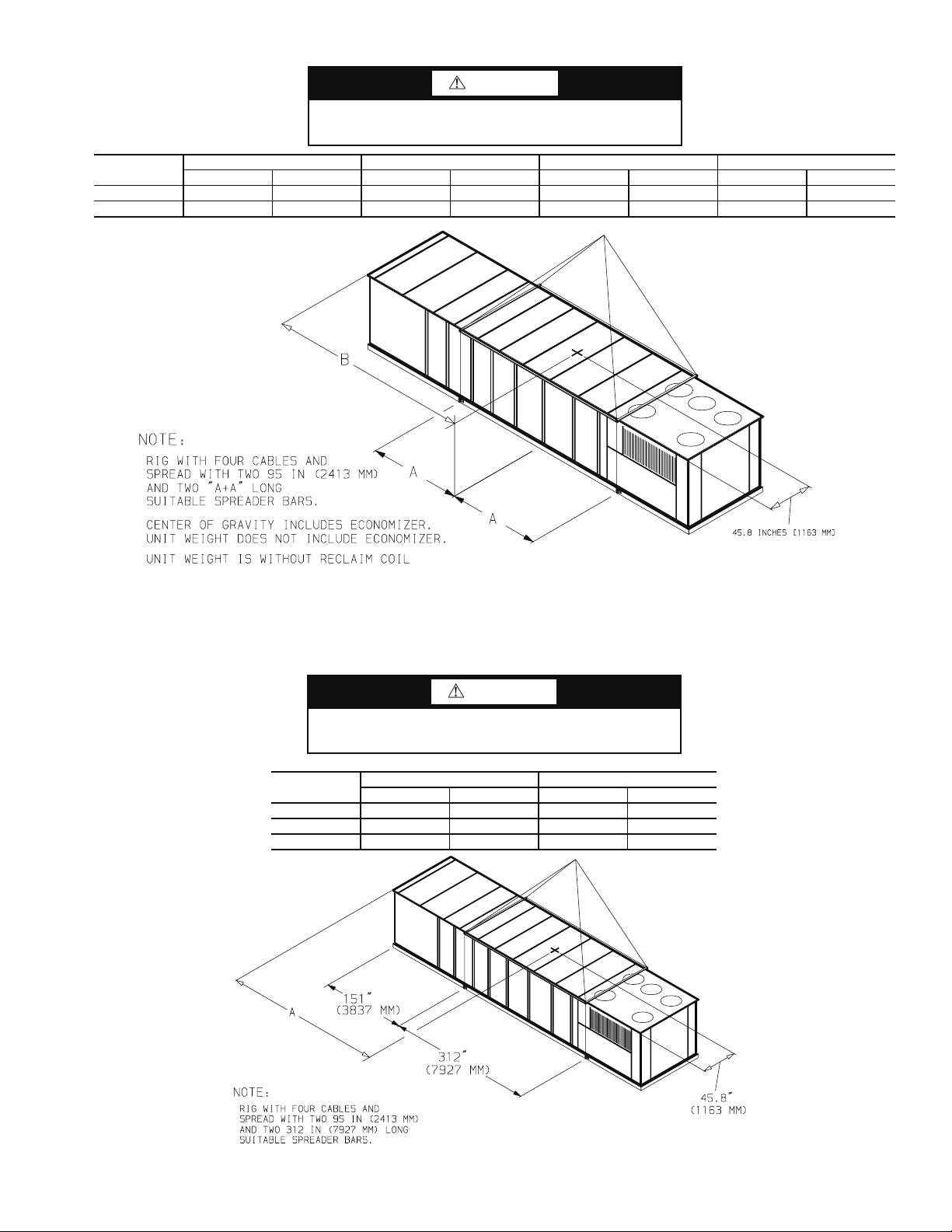
CAUTION
1. ALL PANELS MUST BE IN PLACE WHEN RIGGING.
2. DO NOT ATTEMPT TO FORK THESE UNITS.
NOTICE TO RIGGERS
UNIT
48Z055 9548 4330 121.50 3085.5 248.50 6312 530 240.9
48Z060 9668 4385 121.50 3085.5 248.50 6312 530 240.9
WEIGHT A B ECONOMIZER
lb kg in. mm in. mm lb kg
Fig. 12 — Rigging Label — Size 055,060 Units (Extended Chassis)
CAUTION
1. ALL PANELS MUST BE IN PLACE WHEN RIGGING.
2. DO NOT ATTEMPT TO FORK THESE UNITS.
UNIT
48Z075 13,380 6069 298.9 7591
48Z090 13,590 6164 300.7 7637
48Z105 14,320 6495 309.9 7873
NOTICE TO RIGGERS
WEIGHT A
lb kg in. mm
Fig. 13 — Rigging Label — 48ZT,ZW075-105 Units (High-Capacity Power Exhaust Units)
21
Page 22

3
B
4
UNITS 48ZG,ZN SIZE
VERTICAL SUPPLY AND RETURN/
LOW GAS HEAT
VERTICAL SUPPLY AND RETURN/
HIGH GAS HEAT
VERTICAL SUPPLY AND RETURN/
EXTENDED CHASSIS/LOW GAS HEAT
VERTICAL SUPPLY AND RETURN/
EXTENDED CHASSIS/HIGH GAS HEAT
2
A
CORNER WEIGHTS (lb)
1 2 3 4 ft-in. ft-in.
030 1968 1004 1005 1964 5,941 14- 9
035 1851 1184 1142 1889 6,066 14-11 3-913/
040 2246 1177 1179 2239 6,841 17- 27/
050 2264 1182 1179 2256 6,881 17- 4 3-913/
055 2478 2140 2144 2468 9,230 19- 7 3-913/
060 2557 2211 2212 2549 9,530 19- 7 3-913/
070 2648 2330 2334 2638 9,950 21- 0 3-913/
075 2955 2447 2445 2953 10,800 21- 71/
090 3035 2471 2471 3033 11,010 21- 97/
105 3342 2529 2529 3340 11,740 22- 6 3-913/
030 2000 1037 1038 1995 6,070 14- 81/
035 2061 1038 1037 2059 6,195 14-10 3-913/
040 2277 1210 1213 2270 6,970 17- 17/
050 2301 1206 1205 2297 7,010 17- 3 3-913/
055 2510 2168 2172 2500 9,350 19- 7 3-913/
060 2587 2242 2237 2584 9,650 19- 7 3-913/
070 2683 2361 2365 2672 10,080 21- 0 3-913/
075 3015 2474 2472 3013 10,974 21- 89/
090 3095 2499 2498 3092 11,184 21-107/
105 3405 2554 2554 3401 11,914 22- 7 3-913/
030 2133 1089 1091 2127 6,441 16- 111/
035 2198 1087 1087 2194 6,566 16- 37/
040 2411 1262 1264 2404 7,341 18- 71/
050 2434 1259 1256 2432 7,381 18- 85/
055 2617 2251 2255 2607 9,730 20- 9 3-913/
060 2698 2320 2325 2687 10,030 20- 9 3-913/
030 2188 1100 1101 2182 6,570 16- 23/
035 2187 1163 1161 2184 6,695 18- 67/
040 2454 1284 1287 2446 7,470 18- 71/
050 2017 1740 1738 2014 7,510 20- 9 3-913/
055 2649 2279 2283 2639 9,850 20- 9 3-913/
060 3442 1787 1791 3431 10,450 16- 09/
1
TOTAL
(lb)
AB
1
/
8
8
2
16
8
8
16
16
16
8
2
8
4
16
2
16
3-913/
3-913/
3-913/
3-913/
3-913/
3-913/
3-913/
3-913/
3-913/
3-913/
3-913/
3-913/
3-913/
3-913/
3-913/
3-913/
16
16
16
16
16
16
16
16
16
16
16
16
16
16
16
16
16
16
16
16
16
16
16
16
16
16
16
16
16
16
16
16
WITH HIGH-CAPACITY POWER EXHAUST
UNITS 48ZT,ZW
VERTICAL SUPPLY AND RETURN/
LOW GAS HEAT, HIGH-CAPACITY
POWER EXHAUST
VERTICAL SUPPLY AND RETURN/
HIGH GAS HEAT, HIGH-CAPACITY
POWER EXHAUST
UNITS 48Z6,Z8
WITH RETURN/EXHAUST FAN
VERTICAL SUPPLY AND RETURN
LOW GAS HEAT,
RETURN/EXHAUST FAN
VERTICAL SUPPLY AND RETURN
HIGH GAS HEAT,
RETURN/EXHAUST FAN
Fig. 14 — Weight Distribution and Center of Gravity
SIZE
CORNER WEIGHTS (lb)
1 2 3 4 ft-in. ft-in.
TOTAL
(lb)
075 3551 3053 3049 3551 13,204 24- 9
090 3629 3080 3075 3630 13,414 24- 15/
105 3948 3126 3121 3948 14,144 25- 91/
075 3611 3081 3076 3611 13,380 24-107/
090 3691 3106 3102 3691 13,590 25- 03/
105 4008 3155 3150 4008 14,320 25- 915/
SIZE
075 2802 3002 3008 2868 11,740 19-4 3-9
090 2940 3029 3035 2946 11,950 19-6 3-913/
CORNER WEIGHTS (lb)
1 2 3 4 ft-in. ft-in.
TOTAL
(lb)
105 3242 3091 3098 3249 12,680
075 2921 3029 3036 2928 11,914 19-6 3-913/
090 2999 3056 3063 3006 12,124 19-7 3-913/
105 3304 3116 3123 3311 12,854
AB
13
/
8
8
8
4
3-913/
16
3-913/
3-913/
3-913/
3-913/
3-913/
16
AB
20-2
20-4
3-913/
3-913/
16
16
16
16
16
16
13
/
16
16
16
16
16
16
22
Page 23

Condensate Drain Connections — There are a to-
tal of five drain connections required on each unit: one primary
drain (on right-hand side of the unit) and four secondary drains
(two on each side of unit).
PRIMARY DRAIN — The primary drain is a 2-in. NPT pipe
connection located on the right-hand side of the unit looking at
the unit from the return air end. See Fig. 15-24.
With field-supplied fittings and pipe sections, plumb the primary condensate drain to the 2-in. FPT connector on the base
rail. Use a trap height of at least 4-in. for size 030-070 units
and 7-in. for size 075-105 units. See Fig. 24 and 25. Install with
a height dimension of at least 2-in. from the top of the exit pipe
from the trap section to the bottom of the connector. Apply a
bead of RTV or similar sealant around the pipe joint at the connector in the base rail.
SECONDARY DRAINS (Units Installed on
Curb) — There are two secondary drain connections on each
side of the unit. See Fig. 26. There are secondary drains on
each side of the unit in the filter section and one on each side of
the unit in the supply fan section. There are labels marking
each location on the unit base rail. See Fig. 15-23.
Locate the four 1
mounting screws (shipped in a bag taped to the basepan in the
supply fan section, located behind the access panel marked
FAN SECTION). The drain couplings are a 10-gage plate with
1
a 1
/4 in. half coupling welded to the plate.
At each secondary drain hole location, there is a 1
hole pre-drilled in the bottom of the base rail, surrounded by
four 0.20-in. engagement holes. Install a drain coupling assembly using screws provided at each secondary drain hole location. See Fig. 27. Do not attach any drain coupling assemblies
in the condenser section base rail.
Using field-supplied fittings and pipe sections, assemble Utraps at each secondary drain fitting. See Fig. 28. Provide a
minimum size of ½-in. pipe for secondary drains. Use a trap at
least 4-in. deep for size 030-070 units and 7-in. deep for size
075-105 units. Apply a bead of RTV or similar sealant around
the drain assemblies.
Consult local plumbing codes for direction on joining multiple drain lines. Total size of any combined line does not need
to exceed nominal 2-in. size of primary drain connection.
1
/4-in. drain coupling assemblies and
3
/8-in.
Fill the U-traps at the secondary drain locations prior to unit
start-up. Also check the U-traps before each cooling season to
ensure the traps are filled and functioning properly.
SECONDARY DRAINS (Units Installed on Steel Beam or
Slab) — There are two secondary drain connections required
on each side of the unit. See Fig. 26. There are secondary
drains on each side of the unit in the filter section and one on
each side of the unit in the supply fan section. There are labels
marking each location on the unit base rail. See Fig. 15-23. Prior to final positioning of the unit, apply a bead of RTV or similar sealant around each secondary drain hole in the bottom of
the unit base rail. Then position the unit into final location.
Locate the four 1
1
/4-in. drain coupling assemblies and
mounting screws (shipped in a bag taped to the basepan in the
supply fan section, located behind the access panel marked
FAN SECTION). The drain couplings are a 10-gage plate with
1
a 1
/4 in. half coupling welded to the plate.
After final positioning of the unit, perform the following
procedure:
1. At each of the four secondary drain locations (marked
with labels on the unit base rail), position the drain coupling assembly in the side of the base rail. Mark the
screw holes and the drain hole locations on the base rail.
2. Drill holes for drain outlet (use 1
the mounting screws (use
3
3
/8-in. hole saw) and for
/16-in. drill bit).
3. Install a drain coupling assembly using screws provided
at each secondary drain hole location.
4. Using field-supplied fittings and pipe sections, assemble
U-traps at each secondary drain fitting. See Fig. 28. Provide minimum size of ½-in. pipe for secondary drains.
Use a trap at least 4-in. deep for size 030-070 units and
7-in. deep for size 075-105 units.
5. Apply a bead of RTV or similar sealant around the drain
assemblies.
Consult local plumbing codes for direction on joining multiple drain lines. Total size of any combined line does not need
to exceed nominal 2-in. size of primary drain connection.
Fill the U-traps at the secondary drain locations prior to unit
start-up. Also check the U-traps before each cooling season to
ensure the traps are filled and functioning properly.
23
Page 24

→
Fig. 15 — Base Unit Dimensional Drawing — 48ZG,ZN030,035 (Standard Chassis)
24
Page 25

25
Fig. 16 — Base Unit Dimensional Drawing — 48ZG,ZN040,050 (Standard Chassis)
Page 26

26
Fig. 17 — Base Unit Dimensional Drawing — 48ZG,ZN055-070 (Standard Chassis)
Page 27

a48-8451
27
Fig. 18 — Base Unit Dimensional Drawing — 48ZG,ZN075-105 (Standard Chassis)
Page 28
28
Fig. 19 — Base Unit Dimensional Drawing — 48ZG,ZN030,035 (Extended Chassis)
Page 29

29
Fig. 20 — Base Unit Dimensional Drawing — 48ZG,ZN040,050 (Extended Chassis)
Page 30

a48-8452
30
Fig. 21 — Base Unit Dimensional Drawing — 48ZG,ZN055,060 (Extended Chassis)
Page 31

a48-8453
4.65]
[10
[352]
1'-1 3/4"
POWER
[1933]
6'-4 1/8"
Fig. 22 — Base Unit Dimensional Drawing — 48ZT,ZW075-105 (Units with High-Capacity Power Exhaust)
CONTROL
[22.35] 0'-0 7/8" D LOW VOLTAGE
31
Page 32

a48-8454
32
Fig. 23 — Base Unit Dimensional Drawing — 48Z6,Z8075-105 (Units with Return/Exhaust Fan)
Page 33

Fig. 24 — Primary Drain Connection
A = 4-in. (102 mm) min — Sizes 030-070
7-in. (178 mm) min — Sizes 075-105
Fig. 25 — Slab-Mounted Condensate
Drain Piping Details
Fig. 26 — Secondary Condensate Drain Location
Fig. 27 — Secondary Drain Seal Plate Location
A = 4-in. (102 mm) min — sizes 030-070
7-in. (178 mm) min — sizes 075-105
Fig. 28 — Curb-Mounted Condensate
Drain Pipe Details
Install Outdoor Hoods (48ZG,ZN,Z6,Z8 Units)
UNIT SIZES 030-050
25% Outdoor-Air Hoods (Units without Economizer
Option) (Fig. 29)
1. Outdoor-air hoods are shipped bolted to the unit in a shipping position. Remove the 6 screws holding each 25%
outdoor air hood shipping cover in place.
2. Remove the holddown screw from each upper corner of
each hood.
3. Pivot hoods outward (2 hoods).
4. Install 17 screws around outside of each hood. (Screws
are in the fastener package taped to the basepan inside the
fan section.)
5. Apply a bead of RTV or similar sealant to corner of each
hood at pivot point to prevent water leaks. See Fig. 30.
Economizer Hoods (Units with Economizer Option)
(Fig. 31 and 32)
1. Remove the 4 screws holding each of the 2 economizer
side hoods in place.
2. Pivot hoods outwards (2 hoods).
3. Apply seal strip to vertical flange of hood sides.
4. Install hood sides of hood top using 19 screws (7 each
side, 5 top). Screws are in fastener package located with
the hood sides and seal strip which is taped inside the
unit.
5. Apply a bead of RTV or similar sealant to corners of
economizer hoods to prevent water leaks.
UNIT SIZES 055-105
25% Outdoor-Air Hoods (Fig. 33)
are factory installed on the 055-105 units.
Economizer Hoods (Units with Economizer Option) (Fig. 34-36)
1. Remove the 6 screws holding each of the 4 economizer
shipping covers in place.
2. Remove the holddown screw from each upper corner of
each economizer hood.
3. Pivot hoods outward (4 hoods).
4. Apply seal strip to vertical flange of hood sides.
5. Install 18 screws (5 each side, 6 top, and 2 bottom)
around the outside of each hood. (Screws are in the fastener package taped to the basepan inside the fan section.)
6. Apply a bead of RTV or similar sealant to corner of economizer hood at pivot point to prevent water leaks. (See
Fig. 30.)
— The outdoor-air hoods
33
Page 34

OUTDOOR
AIR HOOD
OUTDOOR
AIR HOOD
OUTDOOR
AIR HOODS
(FIXED)
Fig. 29 — Outdoor Air Hood Installation
(Sizes 030-050)
OUTDOOR-AIR HOOD
RTV
(ALL HOODS)
Fig. 30 — Outdoor-Air and Economizer Hood
SIDE HOOD
(ROTATE
OPEN)
Fig. 33 — 25% Outdoor-Air Hood Location
SIDE HOODS
(ROTATE OPEN)
END HOODS
4”
(FIXED)
SIDE HOODS
(ROTATE
OPEN)
Fig. 34 — Economizer Outdoor-Air Hood
Installation (Sizes 055-105)
SIDE HOODS
(ROTATE OPEN)
SIDE HOOD
(ROTATE
END HOOD
(FIXED)
OPEN)
Fig. 31 — Economizer Outdoor-Air Hood
Installation (Sizes 030-050)
SIDE HOOD
(ROTATE
OPEN)
END HOOD
(FIXED)
SIDE HOOD
(ROTATE
OPEN)
POWER EXHAUST (FIXED)
Fig. 32 — Economizer with Power Exhaust
Outdoor-Air Hood Installation (Sizes 030-050)
34
END HOODS
(FIXED)
POWER
EXHAUST (FIXED)
SIDE HOODS
(ROTATE
OPEN)
Fig. 35 — Economizer with Power Exhaust
Outdoor-Air Hood Installation (Sizes 055-105)
SIDE HOODS
(ROTATE OPEN)
END HOODS
(FIXED)
RETURN/
EXHAUST (FIXED)
SIDE HOODS
(ROTATE
OPEN)
Fig. 36 — Economizer with Return/Exhaust
Fan Outdoor-Air Hood Installation
(48Z6,Z8075-105 Units)
Page 35

Install Economizer Hoods (48ZT,ZW Units) —
The economizer uses a total of 4 outdoor intake hoods, 2 on
each side of the unit. See Fig. 37. Two small hoods (one per
side) are factory-installed and are pivoted inside the unit chassis for shipment. Two large hoods are shipped in packages
located inside the unit. The large hoods (1 on each side) require
field assembly and mounting.
INSTALL SMALL HOODS — To install the small economizer hoods, perform the following procedure:
1. Remove the 10 screws holding each of the small economizer hood shipping covers in place.
2. Pivot hoods outward. (There are a total of 2 hoods.)
3. Apply seal strip to vertical flange of hood sides.
4. Install 15 screws (4 each side, 7 across top) around the
outside of each hood. Screws are in the fastener package
taped to the basepan inside the fan section.
5. Apply a bead of RTV or similar sealant to corner of economizer hood at pivot point to prevent water leaks. (See
Fig. 30.)
INSTALL LARGE HOODS — Large hoods are shipped disassembled in the economizer section of the unit behind the
large economizer hood shipping cover. See Fig. 38 for assembly details for large economizer hoods. To install the large
economizer hoods, perform the following procedure:
1. Remove the 17 screws holding each of the large economizer hood shipping covers in place.
2. Remove the packages containing the disassembled large
economizer hoods (total of 2 packages). Each package
contains the following: left hood side, right hood side,
hood top, hood front, top filter flange, side filter flanges
(4), bottom support, front support, filters (6), filter clips
(9), seal strip, fasteners.
3. Place seal strip on backside of bottom support along entire length of support, covering 6 clearance holes.
4. Attach bottom support piece to unit. Be sure seal strip is
between bottom support and panel on unit.
5. Place seal strip on
3
/4-in. flange on both the left and right
hood side.
6. Attach the side filter flanges to the left and right hood
sides, 2 on each hood side.
7. Attach left and right hood sides to unit. Be sure seal strip
is between hood side and unit.
8. Place seal strip on
3
/4-in. flange on hood top.
9. Attach top filter flange to hood top.
10. Attach top hood to unit and to hood sides. Be sure seal
strip is between hood top and unit.
11. Attach front support between left and right hood sides.
12. Place seal strip on all filter flanges.
13. Attach filter clips to front and bottom supports.
14. Install filters and filter clips. Filters are held in place with
filter clips.
15. Attach hood front to hood top and sides.
16. Apply RTV or similar sealant to 6 places shown in
Fig. 38.
EXHAUST
AIR
PE VFD
POWER EXHAUST
ACCESS DOOR
AUXILIARY
CONTROL BOX
LARGE ECONOMIZER
HOOD LOCATION
ACCESS DOOR
LEGEND
PE VFD — Power Exhaust Variable Frequency Drive
Fig. 37 — Economizer Hood Location — 48ZT,ZW Units
SMALL ECONOMIZER
HOOD LOCATION
35
Page 36

DETAIL Z
SCALE 3:4
SEE DETAIL Z
AND BOTH ENDS OF
BOTTOM FILTER ROW
APPLY RTV IN THE
INDICATED AREAS
Fig. 38 — Large Economizer Hood Assembly
Field Wire Routing
UNIT SIZES 030-050 — Field wiring can be brought into the
unit through the basepan and roof curb or through the corner
post in the side of the unit next to the control box.
1
A 3
coupling for 24 v control wiring are provided in the basepan.
There are two 4
power wiring.
wiring out through one of the 4
supplied disconnect and then back into the unit through the other knockout. See Fig. 39 for recommended disconnect location.
wiring from field-supplied disconnect through top 4
knockouts into unit.
unit, a
next to the control box.
UNIT SIZES 055-105 — Field wiring is brought into the unit
through the bottom of the control box. Wiring can be brought
through the roof curb through field-supplied watertight connections. See Fig. 40 and 41.
24 v control wiring are provided in the bottom of the control
box. Field-supplied couplings must be used when routing wiring into the control box.
/2-in. NPT coupling for field power and a 3/4-in. NPT
5
/8-in. knockouts in the corner post for field
If field power wiring is brought through the roof curb, route
If power wiring is brought through the side of the unit, route
If control wiring is to be brought in through the side of the
7
/8-in. diameter hole must be drilled in the corner post
5
A 4
/32-in. hole for field power wiring and a 7/8-in. hole for
5
/8-in. knockouts to the field-
5
/8-in.
See Fig. 40 and 41 for recommended disconnect location.
Field Electrical Connections
IMPORTANT: The 48ZN,ZW,Z8 units generate, use,
and can radiate radio frequency energy. If units are not
installed and used in accordance with these instructions,
they may cause radio interference. They have been
tested and found to comply with limits of a Class A
computing device as defined by FCC (Federal Communications Commission) regulations, Subpart J of Part 15,
which are designed to provide reasonable protection
against such interference when operated in a commercial
environment.
POWER WIRING — Units are factory wired for the voltage
shown on the unit nameplate. The main terminal block is suitable for use with aluminum or copper wires. Maximum wire
size varies according to disconnect size.
Units Without Factory-Installed Disconnect
ing units, provide a disconnect per NEC (National Electrical
Code) of adequate size (MOCP [Maximum Overcurrent Protection] of unit is on the informative plate). All field wiring
must comply with NEC and all local codes. Size wire based on
MCA (Minimum Circuit Amps) on the unit informative plate.
See Fig. 42 for power wiring connections to the unit power terminal block and equipment ground. Maximum wire size is two
(2) 500 MCM (thousand circular mils) conductors per pole.
— When install-
36
Page 37

Units with Factory-Installed Disconnect
— The factoryinstalled disconnect is an interlocking, door-type. The disconnect handle locks the door when it is in the ON position. The
disconnect handle must be in the OFF position to open the control box door. The disconnect is located in a separate control
box behind the control box door for all units. See Fig. 43.
All field wiring must comply with NEC and all local codes.
Wire must be sized based on MCA (Minimum Circuit Amps)
on the unit informative plate. See Fig. 44 for power wiring connections to the unit disconnect and equipment ground.
DISCONNECT SIZE
200 Amps
400 Amps
600 Amps
Operating Voltage
— Operating voltage to the compressor
QUANTITY...MAXIMUM WIRE SIZE
(MCM)
1...300
1...600
2...600
must be within the voltage range indicated on the unit nameplate. Voltages between phases must be balanced within 2%,
and the current must be balanced within 10%. See Tables 7-16
for unit electrical data.
Use the following formula to determine the percentage of
voltage imbalance.
Voltage Imbalance
= 100 x
max voltage deviation from average voltage
average voltage
Example: Supply voltage is 460-3-60.
AB = 452 v
BC = 464 v
AC = 455 v
Average Voltage =
455 + 464 + 455
1371
=
3
3
= 457
Determine maximum deviation from average voltage:
(AB) 457 – 452 = 5 v
(BC) 464 – 457 = 7 v
(AC) 457 – 455 = 2 v
Maximum deviation is 7 v.
Determine percent voltage imbalance:
% Voltage Imbalance = 100 x
7
457
= 1.53%
This amount of phase imbalance is satisfactory as it is be-
low the maximum allowable 2%.
IMPORTANT: If the supply voltage phase imbalance is
more than 2%, contact local utility immediately.
Unit failure as a result of operation on improper line voltage
or excessive phase imbalance constitutes abuse and may cause
damage to electrical components.
CAUTION
Use care when drilling into corner post to avoid damage to condenser coil.
Fig. 39 — Disconnect Location — Size 030-050 Units
37
Page 38

CAUTION
Use care when drilling into corner post to avoid damage to condenser coil.
Fig. 40 — Disconnect Location — 48ZG,ZN055-105 and 48Z6,Z8075-105 Units
CAUTION
Use care when drilling into corner post to avoid damage to condenser coil.
Fig. 41 — Disconnect Location — 48ZT,ZW075-105 Units
38
Page 39

TB1
21
22
23
EQUIP GND
FACTORY
WIRE
11
22 21
12
13
DISCONNECT PER NEC
23
DISCONNECT
PER NEC
EQUIP
GND
LEGEND
EQUIP — Equipment
GND — Ground
NEC — National Electrical Code
TB — Terminal Block
Fig. 42 — Field Power Wiring Connections
13 12 11
FIELD
WIRE
LEGEND
EQUIP — Equipment
GND — Ground
NEC — National Electrical
Code
Fig. 44 — Field Power Wiring Connections
for Factory-Installed Disconnect
Fig. 43 — Factory-Installed Disconnect Location
39
Page 40

Table 7 — Electrical Data, 48ZG,ZN030 Units
NOMINAL
VO LTAGE
(3 Ph 60 Hz)
VO LTAGE
RANGE
COMPRESSOR
No. 1 No. 2
RLA LRA RLA LRA Qty
OFM IFM
Tot al
Hp FLA
FLA
1
/224.2/22.0
7
10 30.8/28.0
6.6
208/230 187-254 53.2 266 53.2 266 2
(ea)
15 46.2/42.0
20 59.4/54.0
25 74.8/68.0
1
7
11.0
/
2
10 14.0
460
414-508 28.8 120 28.8 120 2
3.3
(ea)
15 21.0
20 27.0
25 34.0
1
7
9.0
/
2
10 11.0
575
518-632 23.1 96 23.1 96 2
2.4
(ea)
15 17.0
20 22.0
25 27.0
LEGEND NOTE: Units use 1 (low heat) or 2 (high heat) combustion fan motors rated at
FLA — Full Load Amps
Hp — Nominal Horsepower
IFM — Indoor (Supply) Fan Motor
LRA — Locked Rotor Amps
MCA — Minimum Circuit Amps (for wire sizing)
MOCP — Maximum Overcurrent Protection
OFM — Outdoor (Condenser) Fan Motor
RLA — Rated Load Amps
0.3 FLA each.
EXHAUST
FAN
Tot al
Hp
— —/— 157.1/154.9 200/200
6 21.2/19.2 178.3/174.1 225/225
10 33.4/30.4 190.5/185.3 225/225
15 48.4/44.0 205.5/198.9 250/250
20 61.6/56.0 220.8/211.6 250/250
— —/— 163.7/160.9 200/200
6 21.2/19.2 184.9/180.1 225/225
10 33.4/30.4 197.1/191.3 250/250
15 48.4/44.0 212.1/204.9 250/250
20 62.0/56.0 227.4/217.6 250/250
— —/— 179.1/174.9 225/225
6 21.2/19.2 184.9/180.1 250/225
10 33.4/30.4 197.1/191.3 250/250
15 48.4/44.0 212.1/204.9 250/250
20 62.0/56.0 227.4/217.6 300/250
— —/— 193.9/187.1 250/225
6 21.2/19.2 215.1/206.3 250/250
10 33.4/30.4 227.3/217.5 250/250
15 48.4/44.0 242.3/231.1 300/250
20 62.0/56.0 256.0/243.6 300/250
— —/— 213.1/204.6 250/225
6 21.2/19.2 234.3/223.8 300/250
10 33.4/30.4 246.5/248.6 300/300
15 48.4/44.0 261.5/248.6 300/300
20 62.0/56.0 274.7/260.6 300/300
— — 82.4 110
6 9.6 92.0 110
10 15.2 97.6 125
15 22.0 104.4 125
20 28.0 110.4 125
— — 85.4 110
6 9.6 95.0 110
10 15.2 100.6 125
15 22.0 107.4 125
20 28.0 113.4 125
— — 92.4 110
6 9.6 102.0 125
10 15.2 107.6 125
15 22.0 114.4 125
20 28.0 120.4 125
— — 98.4 125
6 9.6 108.0 125
10 15.2 113.6 125
15 22.0 120.4 125
20 28.0 126.4 150
— — 106.7 125
6 9.6 116.3 150
10 15.2 121.9 150
15 22.0 128.7 150
20 28.0 134.7 150
—— 65.8 80
6 7.8 73.6 90
10 12.2 78.0 100
15 18.0 83.8 100
20 22.0 87.8 110
—— 67.8 90
6 7.8 75.6 90
10 12.2 80.0 100
15 18.0 85.8 100
20 22.0 89.8 110
—— 73.8 90
6 7.8 81.6 100
10 12.2 86.0 100
15 18.0 91.8 110
20 22.0 95.8 110
— — 78.8 100
6 7.8 86.6 100
10 12.2 91.0 110
15 18.0 96.8 110
20 22.0 100.8 110
— — 84.8 110
6 7.8 92.6 110
10 12.2 97.0 110
15 18.0 102.8 125
20 22.0 106.8 125
Tot al
FLA
POWER SUPPLY
MCA MOCP
40
Page 41

Table 8 — Electrical Data, 48ZG,ZN035 Units
NOMINAL
VO LTAGE
(3 Ph 60 Hz)
VO LTAGE
RANGE
COMPRESSOR
No. 1 No. 2
RLA LRA RLA LRA Qty
OFM IFM
Tot al
Hp FLA
FLA
1
/224.2/22.0
7
10 30.8/28.0
6.6
208/230 187-254 53.2 266 69.2 345 2
(ea)
15 46.2/42.0
20 59.4/54.0
25 74.8/68.0
1
7
11.0
/
2
10 14.0
460
414-508 28.8 120 34.6 173 2
3.3
(ea)
15 21.0
20 27.0
25 34.0
1
7
9.0
/
2
10 11.0
575
518-632 23.1 96 26.7 120 2
2.4
(ea)
15 17.0
20 22.0
25 27.0
LEGEND NOTE: Units use 1 (low heat) or 2 (high heat) combustion fan motors rated at
FLA — Full Load Amps
Hp — Nominal Horsepower
IFM — Indoor (Supply) Fan Motor
LRA — Locked Rotor Amps
MCA — Minimum Circuit Amps (for wire sizing)
MOCP — Maximum Overcurrent Protection
OFM — Outdoor (Condenser) Fan Motor
RLA — Rated Load Amps
0.3 FLA each.
EXHAUST
FAN
Tot al
Hp
— —/— 177.1/174.9 225/225
10 33.4/30.4 210.5/205.3 250/250
15 48.4/44.0 225.5/218.9 250/250
20 61.6/56.0 238.7/230.9 300/300
— —/— 183.7/180.9 250/250
10 33.4/30.4 217.1/211.3 250/250
15 48.4/44.0 232.1/224.9 300/250
20 62.0/56.0 245.3/236.9 300/300
— —/— 199.1/194.9 250/250
10 33.4/30.4 232.5/225.3 300/250
15 48.4/44.0 247.5/238.9 300/300
20 62.0/56.0 260.7/250.9 300/300
— —/— 212.3/206.9 250/250
10 33.4/30.4 245.7/237.3 300/300
15 48.4/44.0 260.7/250.9 300/300
20 62.0/56.0 273.9/262.9 300/300
— —/— 229.1/220.9 300/250
10 33.4/30.4 262.5/251.3 300/300
15 48.4/44.0 277.5/264.9 350/300
20 62.0/56.0 290.7/276.9 350/300
— — 89.7 110
10 15.2 104.9 125
15 22.0 111.7 125
20 28.0 117.7 150
— — 92.7 125
10 15.2 107.9 125
15 22.0 114.7 125
20 28.0 120.7 150
— — 99.7 125
10 15.2 114.9 125
15 22.0 121.7 150
20 28.0 127.7 150
— — 105.7 125
10 15.2 120.9 150
15 22.0 127.7 150
20 28.0 133.7 150
— — 112.7 125
10 15.2 127.9 150
15 22.0 134.7 150
20 28.0 140.7 175
—— 70.3 90
10 12.2 82.5 100
15 18.0 88.3 110
20 22.0 92.3 110
—— 72.3 90
10 12.2 84.5 110
15 18.0 90.3 110
20 22.0 94.3 110
— — 78.3 100
10 12.2 90.5 110
15 18.0 96.3 110
20 22.0 100.3 125
— — 83.3 100
10 12.2 95.5 110
15 18.0 101.3 125
20 22.0 105.3 125
— — 88.4 110
10 12.2 100.6 125
15 18.0 106.4 125
20 22.0 110.4 125
Tot al
FLA
6 21.2/19.2 198.3/194.1 250/250
6 21.2/19.2 204.9/200.1 250/250
6 21.2/19.2 220.3/214.1 250/250
6 21.2/19.2 233.5/226.1 300/250
6 21.2/19.2 250.3/240.1 300/300
6 9.6 99.3 125
6 9.6 102.3 125
6 9.6 109.3 125
6 9.6 115.3 125
6 9.6 122.3 150
6 7.8 78.1 100
6 7.8 80.1 100
6 7.8 86.1 110
6 7.8 91.1 110
6 7.8 96.2 110
POWER SUPPLY
MCA MOCP
41
Page 42

Table 9 — Electrical Data, 48ZG,ZN040 Units
NOMINAL
VO LTAGE
(3 Ph 60 Hz)
VO LTAGE
RANGE
COMPRESSOR
No. 1 No. 2
RLA LRA RLA LRA Qty
OFM IFM
Tot al
Hp FLA
FLA
1
/224.2/22.0
7
10 30.8/28.0
6.6
208/230 187-254 69.2 345 69.2 345 3
(ea)
15 46.2/42.0
20 59.4/54.0
25 74.8/68.0
1
7
11.0
/
2
10 14.0
15 21.0
460
414-508 34.6 173 34.6 173 3
3.3
(ea)
20 27.0
25 34.0
30 40.0
1
7
9.0
/
2
10 11.0
575
518-632 26.7 120 26.7 120 3
2.4
(ea)
15 17.0
20 22.0
25 27.0
LEGEND NOTE: Units use 1 (low heat) or 2 (high heat) combustion fan motors rated at
FLA — Full Load Amps
Hp — Nominal Horsepower
IFM — Indoor (Supply) Fan Motor
LRA — Locked Rotor Amps
MCA — Minimum Circuit Amps (for wire sizing)
MOCP — Maximum Overcurrent Protection
OFM — Outdoor (Condenser) Fan Motor
RLA — Rated Load Amps
0.3 FLA each.
EXHAUST
FAN
Tot al
Hp
— —/— 199.7/197.5 250/250
6 21.2/19.2 220.9/216.7 250/250
10 33.4/30.4 233.1/227.9 300/250
15 48.4/44.0 248.1/241.5 300/300
20 61.6/56.0 261.3/253.5 300/300
— —/— 206.3/203.5 250/250
6 21.2/19.2 227.5/222.7 250/250
10 33.4/30.4 239.7/233.9 300/300
15 48.4/44.0 254.7/247.5 300/300
20 62.0/56.0 267.9/259.5 300/300
— —/— 221.7/217.5 250/250
6 21.2/19.2 242.9/236.7 300/300
10 33.4/30.4 255.1/247.9 300/300
15 48.4/44.0 270.1/261.5 300/300
20 62.0/56.0 283.3/273.5 350/300
— —/— 234.9/229.5 300/250
6 21.2/19.2 256.1/248.7 300/300
10 33.4/30.4 268.3/259.9 300/300
15 48.4/44.0 283.3/273.5 350/300
20 62.0/56.0 296.5/285.5 350/350
— —/— 251.7/243.5 300/300
6 21.2/19.2 272.9/262.7 300/300
10 33.4/30.4 285.1/273.9 350/300
15 48.4/44.0 300.1/287.5 350/350
20 62.0/56.0 313.3/299.5 350/350
— — 98.8 125
6 9.6 108.4 125
10 15.2 114.0 125
15 22.0 120.8 150
20 28.0 126.8 150
— — 101.8 125
6 9.6 111.4 125
10 15.2 117.0 150
15 22.0 123.8 150
20 28.0 129.8 150
— — 108.8 125
6 9.6 118.4 150
10 15.2 124.0 150
15 22.0 130.8 150
20 28.0 136.8 150
— — 114.8 125
6 9.6 124.4 150
10 15.2 130.0 150
15 22.0 138.8 150
20 28.0 142.8 175
— — 121.8 150
6 9.6 131.4 150
10 15.2 137.0 150
15 22.0 143.8 175
20 28.0 149.8 175
— — 129.1 150
6 9.6 138.7 175
10 15.2 144.3 175
15 22.0 151.1 175
20 28.0 157.1 175
— — 76.3 100
6 7.8 84.1 110
10 12.2 88.5 100
15 18.0 94.3 110
20 22.0 98.3 110
— — 78.3 100
6 7.8 86.1 110
10 12.2 90.5 110
15 18.0 96.3 110
20 22.0 100.3 125
— — 84.3 110
6 7.8 92.1 110
10 12.2 96.5 110
15 18.0 102.3 125
20 22.0 106.3 125
— — 89.3 110
6 7.8 97.1 110
10 12.2 101.5 125
15 18.0 107.3 125
20 22.0 101.3 125
— — 94.4 110
6 7.8 102.2 125
10 12.2 106.6 125
15 18.0 112.4 125
20 22.0 116.4 125
Tot al
FLA
POWER SUPPLY
MCA MOCP
42
Page 43

Table 10 — Electrical Data, 48ZG,ZN050 Units
NOMINAL
VO LTAGE
(3 Ph 60 Hz)
VO LTAGE
RANGE
COMPRESSOR
No. 1 No. 2
RLA LRA RLA LRA Qty
OFM IFM
Tot al
Hp FLA
FLA
1
/224.2/22.0
7
10 30.8/28.0
6.6
208/230 187-254 89.7 446 69.2 345 3
(ea)
15 46.2/42.0
20 59.4/54.0
25 74.8/68.0
1
7
11.0
/
2
10 14.0
15 21.0
460
414-508 43.6 223 34.6 173 3
3.3
(ea)
20 27.0
25 34.0
30 40.0
1
7
9.0
/
2
10 11.0
575
518-632 36.5 164 26.7 120 3
2.4
(ea)
15 17.0
20 22.0
25 27.0
LEGEND NOTE: Units use 1 (low heat) or 2 (high heat) combustion fan motors rated at
FLA — Full Load Amps
Hp — Nominal Horsepower
IFM — Indoor (Supply) Fan Motor
LRA — Locked Rotor Amps
MCA — Minimum Circuit Amps (for wire sizing)
MOCP — Maximum Overcurrent Protection
OFM — Outdoor (Condenser) Fan Motor
RLA — Rated Load Amps
0.3 FLA each.
EXHAUST
FAN
Tot al
Hp
— —/— 225.3/223.1 300/300
10 33.4/30.4 258.7/253.5 300/300
15 48.4/44.0 273.7/267.1 350/350
20 61.6/56.0 286.9/279.1 350/350
— —/— 231.9/229.1 300/300
10 33.4/30.4 265.3/259.5 350/300
15 48.4/44.0 280.3/273.1 350/350
20 62.0/56.0 293.5/285.1 350/350
— —/— 247.3/243.1 300/300
10 33.4/30.4 280.7/273.5 350/350
15 48.4/44.0 295.7/287.1 350/350
20 62.0/56.0 308.9/299.1 350/350
— —/— 260.5/255.1 350/300
10 33.4/30.4 293.9/285.5 350/350
15 48.4/44.0 308.9/299.1 350/350
20 62.0/56.0 322.1/311.1 400/400
— —/— 275.9/269.1 350/350
10 33.4/30.4 309.3/299.5 350/350
15 48.4/44.0 324.3/313.1 400/400
20 62.0/56.0 337.5/325.1 400/400
— — 110.0 150
10 15.2 125.2 150
15 22.0 132.0 175
20 28.0 138.0 175
— — 113.0 150
10 15.2 128.2 150
15 22.0 135.0 175
20 28.0 141.0 175
— — 120.0 150
10 15.2 135.2 175
15 22.0 142.0 175
20 28.0 148.0 175
— — 126.0 150
10 15.2 141.2 175
15 22.0 148.0 175
20 28.0 154.0 175
— — 133.0 175
10 15.2 148.2 175
15 22.0 155.0 175
20 28.0 161.0 200
— — 139.0 175
10 15.2 154.2 175
15 22.0 161.0 200
20 28.0 167.0 200
— — 88.5 125
10 12.2 100.7 125
15 18.0 106.5 125
20 22.0 110.5 125
— — 90.5 125
10 12.2 102.7 125
15 18.0 108.5 125
20 22.0 112.5 125
— — 96.5 125
10 12.2 108.7 125
15 18.0 114.5 150
20 22.0 118.5 150
— — 101.5 125
10 12.2 113.7 150
15 18.0 119.5 150
20 22.0 123.5 150
— — 106.5 125
10 12.2 118.7 150
15 18.0 124.5 150
20 22.0 128.5 150
Tot al
FLA
6 21.2/19.2 246.5/242.3 300/300
6 21.2/19.2 253.1/248.3 300/300
6 21.2/19.2 268.5/262.3 350/350
6 21.2/19.2 281.7/274.3 350/350
6 21.2/19.2 297.1/288.3 350/350
6 9.6 119.6 150
6 9.6 122.6 150
6 9.6 129.6 150
6 9.6 135.6 175
6 9.6 142.6 175
6 9.6 148.6 175
6 7.8 96.3 125
6 7.8 98.3 125
6 7.8 104.3 125
6 7.8 109.3 125
6 7.8 114.3 150
POWER SUPPLY
MCA MOCP
43
Page 44

Table 11 — Electrical Data, 48ZG,ZN055 Units
NOMINAL
VO LTAGE
(3 Ph 60 Hz)
208/230 187-254 108 506 74.4 345 26.4
460 414-508 50.6 253 34.6 173 13.2
575 518-632 39.1 176 28.8 120 9.6
LEGEND NOTE: Units use 2 (low heat) or 3 (high heat) combustion fan
FLA — Full Load Amps
Hp — Nominal Horsepower
IFM — Indoor (Supply) Fan Motor
LRA — Locked Rotor Amps
MCA — Minimum Circuit Amps (for wire sizing)
MOCP — Maximum Overcurrent Protection
OFM — Outdoor (Condenser) Fan Motor
RLA — Rated Load Amps
VO LTAGE
RANGE
COMPR
NO. 1
RLA LRA RLA LRA
COMPR
NO. 2
OFM IFM
Tot al
Hp FLA MCA MOCP
FLA
15 46.2/42 281.6/277.4 350/350
20 59.4/54 294.8/289.4 400/350
25 74.8/68 310.2/303.4 400/400
30 88.0/80 323.4/315.4 400/400
40 114.4/104 351.5/339.4 450/400
15 21.0 132.1 175
20 27.0 138.1 175
25 34.0 145.1 175
30 40.0 151.1 200
40 52.0 163.4 200
15 17.0 104.3 125
20 22.0 109.3 125
25 27.0 114.3 150
30 32.0 119.3 150
40 41.0 128.8 150
motors rated at 0.3 FLA each.
BASE UNIT
ONLY
EXHAUST
FAN
Tota lHpTot al
FLA
10 34/30 315.0/307.4 400/400
15 48/44 330.0/321.4 400/400
20 62/56 343.2/333.4 450/400
10 34/30 328.2/319.4 400/400
15 48/44 343.2/333.4 450/400
20 62/56 356.4/345.4 450/450
10 34/30 343.6/333.4 450/400
15 48/44 358.6/347.4 450/450
20 62/56 371.8/359.4 450/450
10 34/30 356.8/345.4 450/450
15 48/44 371.8/359.4 450/450
20 62/56 385.0/371.4 450/450
10 34/30 384.9/369.8 450/450
15 48/44 399.9/383.4 500/450
20 62/56 412.6/395.4 500/500
10 15.2 147.3 175
15 22.0 154.1 200
20 28.0 160.1 200
10 15.2 153.3 200
15 22.0 160.1 200
20 28.0 166.1 200
10 15.2 160.3 200
15 22.0 167.1 200
20 28.0 173.1 200
10 15.2 166.3 200
15 22.0 173.1 200
20 28.0 179.1 225
10 15.2 178.6 225
15 22.0 185.4 225
20 28.0 191.4 225
10 12.2 116.5 150
15 18.0 122.3 150
20 22.0 126.3 150
10 12.2 121.5 150
15 18.0 127.3 150
20 22.0 131.3 150
10 12.2 126.5 150
15 18.0 132.3 150
20 22.0 136.3 175
10 12.2 131.5 150
15 18.0 137.3 175
20 22.0 141.3 175
10 12.2 141.0 175
15 18.0 146.8 175
20 22.0 150.8 175
BASE UNIT WITH
EXHAUST FAN
MCA MOCP
44
Page 45

Table 12 — Electrical Data, 48ZG,ZN060 Units
NOMINAL
VO LTAGE
(3 Ph 60 Hz)
208/230 187-254 108 506 108 506 26.4
460 414-508 50.6 253 50.6 253 13.2
575 518-632 39.1 176 39.1 176 9.6
LEGEND NOTE: Units use 2 (low heat) or 3 (high heat) combustion fan
FLA — Full Load Amps
Hp — Nominal Horsepower
IFM — Indoor (Supply) Fan Motor
LRA — Locked Rotor Amps
MCA — Minimum Circuit Amps (for wire sizing)
MOCP — Maximum Overcurrent Protection
OFM — Outdoor (Condenser) Fan Motor
RLA — Rated Load Amps
VO LTAGE
RANGE
COMPR
NO. 1
RLA LRA RLA LRA
COMPR
NO. 2
OFM IFM
Tot al
Hp FLA MCA MOCP
FLA
15 46.2/42 314.9/310.7 400/400
20 59.4/54 328.1/322.7 400/400
25 74.8/68 343.5/336.7 450/400
30 88.0/80 356.7/348.7 450/450
40 114.4/104 384.8/372.7 450/450
15 21.0 148.1 175
20 27.0 154.1 200
25 34.0 161.1 200
30 40.0 167.1 200
40 52.0 179.4 225
15 17.0 114.6 150
20 22.0 119.6 150
25 27.0 124.6 150
30 32.0 129.6 150
40 41.0 139.6 175
motors rated at 0.3 FLA each.
BASE UNIT
ONLY
EXHAUST
FAN
Tota lHpTot al
FLA
10 34/30 348.3/340.7 450/400
15 48/44 363.3/354.7 450/450
20 62/56 376.6/366.7 450/450
10 34/30 361.5/352.7 450/450
15 48/44 376.5/366.7 450/450
20 62/56 389.7/378.7 450/450
10 34/30 376.9/366.7 450/450
15 48/44 391.9/380.7 450/450
20 62/56 405.1/392.7 500/500
10 34/30 390.1/378.7 450/450
15 48/44 405.1/392.7 500/500
20 62/56 418.3/404.7 500/500
10 34/30 418.2/403.1 500/500
15 48/44 433.2/416.7 500/500
20 62/56 445.9/428.7 500/500
10 15.2 163.3 200
15 22.0 170.1 200
20 28.0 176.1 200
10 15.2 169.3 200
15 22.0 176.1 225
20 28.0 182.1 225
10 15.2 176.3 225
15 22.0 183.1 225
20 28.0 189.1 225
10 15.2 182.3 225
15 22.0 189.1 225
20 28.0 195.1 225
10 15.2 194.6 225
15 22.0 201.4 250
20 28.0 207.4 250
10 12.2 126.8 150
15 18.0 132.6 150
20 22.0 136.6 175
10 12.2 131.8 150
15 18.0 137.6 175
20 22.0 141.6 175
10 12.2 136.8 175
15 18.0 142.6 175
20 22.0 146.6 175
10 12.2 141.8 175
15 18.0 147.6 175
20 22.0 151.6 175
10 12.2 151.3 175
15 18.0 157.1 175
20 22.0 161.1 200
BASE UNIT WITH
EXHAUST FAN
MCA MOCP
45
Page 46

Table 13 — Electrical Data, 48ZG,ZN070 Units
NOMINAL
VOLTAGE
(3 Ph 60 Hz)
208/230 187-254 108 506 142 690 33.0
460 414-508 50.6 253 65.4 345 16.5
575 518-632 39.1 176 52.6 276 12.0
LEGEND NOTE: Units use 2 (low heat) or 3 (high heat) combustion fan
FLA — Full Load Amps
Hp — Nominal Horsepower
IFM — Indoor (Supply) Fan Motor
LRA — Locked Rotor Amps
MCA — Minimum Circuit Amps (for wire sizing)
MOCP — Maximum Overcurrent Protection
OFM — Outdoor (Condenser) Fan Motor
RLA — Rated Load Amps
VOLTAGE
RANGE
COMPR
NO. 1
RLA LRA RLA LRA
COMPR
NO. 2
OFM IFM
Tot al
Hp FLA MCA MOCP
FLA
15 46.2/42 364.8/360.6 500/500
20 59.4/54 378.0/372.6 500/500
25 74.8/68 393.4/386.6 500/500
30 88.0/80 406.6/389.6 500/500
40 114.4/104.0 433.0/422.6 500/500
15 21.0 169.9 225
20 27.0 175.9 225
25 34.0 182.9 225
30 40.0 188.9 250
40 52.0 200.9 250
15 17.0 133.9 175
20 22.0 138.9 175
25 27.0 143.9 175
30 32.0 148.9 200
40 41.0 157.9 200
motors rated at 0.3 FLA each.
BASE UNIT
ONLY
EXHAUST
FAN
Tot alHpTot al
FLA
10 34/30 398.2/390.6 500/500
15 48/44 413.2/404.6 500/500
20 62/56 426.4/416.6 500/500
10 34/30 411.4/402.6 500/500
15 48/44 426.4/416.6 500/500
20 62/56 439.6/428.6 500/500
10 34/30 426.8/416.6 500/500
15 48/44 441.8/430.6 500/500
20 62/56 455.0/442.6 500/500
10 34/30 440.0/428.6 500/500
15 48/44 455.0/442.6 500/500
20 62/56 468.2/454.6 600/500
10 34/30 466.4/453.0 600/500
15 48/44 481.4/466.6 600/600
20 62/56 494.1/478.6 600/600
10 15.2 185.1 250
15 22.0 191.9 250
20 28.0 197.9 250
10 15.2 191.1 250
15 22.0 197.9 250
20 28.0 203.9 250
10 15.2 198.1 250
15 22.0 204.9 250
20 28.0 210.9 275
10 15.2 204.1 250
15 22.0 210.9 275
20 28.0 216.9 275
10 15.2 216.1 250
15 22.0 222.9 250
20 28.0 228.9 250
10 12.2 146.1 175
15 18.0 151.9 200
20 22.0 155.9 200
10 12.2 151.1 200
15 18.0 156.9 200
20 22.0 160.9 200
10 12.2 156.1 200
15 18.0 161.9 200
20 22.0 165.9 200
10 12.2 161.1 200
15 18.0 166.9 200
20 22.0 170.9 200
10 12.2 170.1 200
15 18.0 175.9 225
20 22.0 179.9 225
BASE UNIT WITH
EXHAUST FAN
MCA MOCP
46
Page 47

Table 14 — Electrical Data — 48ZG,ZN075-105 Units
NOMINAL
UNIT
VOLTAGE
SIZE
FLA — Full Load Amps
Hp — Nominal Horsepower
IFM — Indoor (Supply) Fan Motor
LRA — Locked Rotor Amps
MCA — Minimum Circuit Amps (for wire sizing)
MOCP — Maximum Overcurrent Protection
OFM — Outdoor (Condenser) Fan Motor
RLA —
NOTE: Units use 2 (low heat) or 3 (high heat) combustion fan motors
rated at 460 v, single-phase, 60 Hertz and 0.3 FLA each.
(3 Ph
60 Hz)
075 460 414-50850.625365.4345————16.5
090 460 414-50865.434565.4345————19.8
105 460 414-508 50.6 253 34.6 173 50.6 253 34.6 173 19.8
VOLTAGE
RANGE
LEGEND
Rated Load Amps
No. 1 No. 2 No. 3 No. 4
RLA LRA RLA LRA RLA LRA RLA LRA
COMPRESSOR
OFM IFM
Tot al
FLA
BASE
UNIT
ONLY
Hp FLA MCA MOCP
30 40.0 188.9 250
40 52.0 200.9 250
50 65.0 213.9 250
60 77.0 228.8 300
75 96.0 252.5 300
30 40.0 207.0 250
40 52.0 219.0 250
50 65.0 232.0 250
60 77.0 246.9 300
75 96.0 270.6 350
30 40.0 242.9 250
40 52.0 255.2 300
50 65.0 271.5 300
60 77.0 286.5 350
75 96.0 310.2 400
OPTIONAL
POWER
EXHAUST
FAN
Tot alHpTot al
10 15.2 204.1 250
15 22.0 210.9 250
20 28.0 216.9 250
10 15.2 216.1 250
15 22.0 222.9 250
20 28.0 228.9 250
10 15.2 229.1 250
15 22.0 235.9 300
20 28.0 241.9 300
10 15.2 244.0 300
15 22.0 250.8 300
20 28.0 256.8 300
10 15.2 267.7 300
15 22.0 274.5 350
20 28.0 280.5 350
10 15.2 222.2 350
15 22.0 229.0 250
20 28.0 235.0 300
10 15.2 234.2 250
15 22.0 241.0 300
20 28.0 247.0 300
10 15.2 247.2 300
15 22.0 254.0 300
20 28.0 260.0 300
10 15.2 262.1 300
15 22.0 268.9 300
20 28.0 274.9 300
10 15.2 285.8 350
15 22.0 292.6 350
20 28.0 298.6 350
10 15.2 258.1 300
15 22.0 264.9 300
20 28.0 270.9 300
10 15.2 270.4 300
15 22.0 277.2 300
20 28.0 283.2 300
10 15.2 286.7 350
15 22.0 293.5 350
20 28.0 299.5 350
10 15.2 301.7 350
15 22.0 308.5 350
20 28.0 314.5 350
10 15.2 325.4 400
15 22.0 332.2 400
20 28.0 338.2 400
FLA
BASE UNIT
WITH
EXHAUST
FAN
MCA MOCP
47
Page 48

Table 15 — Electrical Data — 48Z6,Z8075-105 Units
VOLTAGE
UNIT
VO LTAGE
SIZE
(3 Ph, 60 Hz)
075 460 41450850.625365.4345———— 5
090 460 41450865.434565.4345———— 6
105 460 414 508 50.6 253 50.6 253 34.6 173 34.6 173 6
FLA — Full Load Amps
Hp — Nominal Horsepower
LRA — Locked Rotor Amps
MCA — Minimum Circuit Amps (for wire sizing)
MOCP — Maximum Overcurrent Protection
RLA — Rated Load Amps
NOTE: Units use 2 (low heat) or 3 (high heat) combustion fan motors
rated at 460 v, single-phase, 60 Hertz and 0.3 FLA each.
LEGEND
RANGE
Min Max RLA LRA RLA LRA RLA LRA RLA LRA Qty FLA Hp FLA Hp
No. 1 No. 2 No. 3 No.4
COMPRESSOR
CONDENSER
FAN MOTOR
3.3
(ea)
3.3
(ea)
3.3
(ea)
EVAPORATOR
FAN MOTO R
30 40.0
40 52.0
50 65.0
60 77.0
75 96.0
30 40.0
40 52.0
50 65.0
60 77.0
75 96.0
30 40.0
40 52.0
50 65.0
60 77.0
75 96.0
RETURN/
EXHAUST
FAN
FLA
(total)
20 27 215.9 250
25 34 222.9 250
30 40 228.9 250
40 52 240.9 300
20 27 227.9 250
25 34 234.9 300
30 40 240.9 300
40 52 252.9 300
20 27 240.9 300
25 34 247.9 300
30 40 253.9 300
40 52 265.9 300
20 27 255.8 300
25 34 262.8 300
30 40 268.8 300
40 52 280.8 350
20 27 279.5 350
25 34 286.5 350
30 40 292.5 350
40 52 304.5 400
20 27 234.0 250
25 34 241.0 300
30 40 247.0 300
40 52 259.0 300
20 27 246.0 300
25 34 253.0 300
30 40 259.0 300
40 52 271.0 300
20 27 259.0 300
25 34 266.0 300
30 40 272.0 300
40 52 284.0 300
20 27 273.9 350
25 34 280.9 350
30 40 286.9 350
40 52 298.9 350
20 27 297.6 350
25 34 304.6 400
30 40 310.6 400
40 52 322.6 400
20 27 269.9 300
25 34 276.9 300
30 40 282.9 300
40 52 294.9 300
20 27 282.2 300
25 34 289.2 300
30 40 295.2 300
40 52 307.2 350
20 27 298.5 350
25 34 305.5 350
30 40 311.5 350
40 52 323.5 350
20 27 313.5 350
25 34 320.5 350
30 40 326.5 400
40 52 338.5 400
20 27 337.2 400
25 34 344.2 400
30 40 350.2 400
40 52 362.2 450
POWER
SUPPLY
MCA MOCP
48
Page 49

Table 16 — Electrical Data — 48ZT,ZW075-105 Units
VO LTAGE
UNIT
SIZE
075
090 460 414-50865.434565.4345————19.8
3 PH,
60 Hz
460 414-50850.625365.4345————16.5
575 518-63239.117652.6276————12.0
VO LTAGE
RANGE
No. 1No. 2No. 3No. 4
RLA LRA RLA LRA RLA LRA RLA LRA
COMPRESSOR
OFM IFM
Tot al
FLA
Hp FLA LRA
30 40.0 230
40 52.0 304
50 65.0 370
60 77.0 453
75 96.0 —
30 32.0 —
40 41.0 —
50 52.0 —
60 62.0 —
30 40.0 230
40 52.0 304
50 65.0 370
60 77.0 453
75 96.0 —
EXHAUST
FAN
Tot alHpTot al
FLA
20 28 216.9 250
30 42 230.9 250
40 54 242.9 300
50 68 256.9 300
60 80 268.9 300
20 28 228.9 250
30 42 242.9 300
40 54 254.9 300
50 68 268.9 300
60 80 280.9 300
20 28 241.9 300
30 42 255.9 300
40 54 267.9 300
50 68 281.9 300
60 80 293.9 350
20 28 256.8 300
30 42 270.8 300
40 54 282.8 350
50 68 296.8 350
60 80 308.8 350
20 28 280.5 350
30 42 294.5 350
40 54 306.5 400
50 68 320.5 400
60 80 332.5 400
20 22 170.9 200
30 34 182.9 225
40 44 192.9 225
50 54 202.9 250
60 64 212.9 250
20 22 179.9 225
30 34 191.9 225
40 44 201.9 250
50 54 211.9 250
60 64 221.9 250
20 22 190.9 225
30 34 202.9 250
40 44 212.9 250
50 54 222.9 250
60 64 232.9 250
20 22 203.2 250
30 34 215.2 250
40 44 225.2 250
50 54 235.2 250
60 64 245.2 300
20 28 235.0 300
30 42 249.0 300
40 54 261.0 300
50 68 275.0 300
60 80 287.0 350
20 28 247.0 300
30 42 261.0 300
40 54 273.0 300
50 68 287.0 350
60 80 299.0 350
20 28 260.0 300
30 42 274.0 300
40 54 286.0 350
50 68 300.0 350
60 80 312.0 350
20 28 274.9 350
30 42 288.9 350
40 54 300.9 350
50 68 314.9 350
60 80 326.9 400
20 28 298.6 350
30 42 312.6 400
40 54 324.6 400
50 68 338.6 400
60 80 350.6 400
BASE UNIT
WITH
EXHAUST FAN
MCA MOCP
49
Page 50

Table 16 — Electrical Data — 48ZT,ZW075-105 Units (cont)
VO LTAGE
UNIT
SIZE
090 575 518-63252.627652.6276————14.4
105
FLA — Full Load Amps
Hp — Nominal Horsepower
IFM — Indoor (Evaporator) Fan Motor
LRA — Locked Rotor Amps
MCA — Minimum Circuit Amps (for wire sizing)
MOCP — Maximum Overcurrent Protection
OFM — Outdoor (Condenser) Fan Motor
RLA — Rated Load Amps
3 PH,
60 Hz
460 414-508 50.6 253 34.6 173 50.6 253 34.6 173 19.8
575 518-632 39.1 176 26.7 120 39.1 176 26.7 120 14.4
VO LTAGE
RANGE
LEGEND NOTE: Units use 2 (low heat) or 3 (high heat) combustion fan
No. 1No. 2No. 3No. 4
RLA LRA RLA LRA RLA LRA RLA LRA
COMPRESSOR
motors rated at 460 v, single-phase, 60 Hertz and 0.3 FLA each.
OFM IFM
Tot al
FLA
Hp FLA LRA
30 32.0 —
40 41.0 —
50 52.0 —
60 62.0 —
30 40.0 230
40 52.0 304
50 65.0 370
60 77.0 453
75 96.0 —
30 32.0 —
40 41.0 —
50 52.0 —
60 62.0 —
EXHAUST
FAN
Tot alHpTot al
FLA
20 22 186.8 225
30 34 198.8 250
40 44 208.8 250
50 54 218.8 250
60 64 228.8 250
20 22 195.8 225
30 34 207.8 250
40 44 217.8 250
50 54 227.8 250
60 64 237.8 250
20 22 206.8 250
30 34 218.8 250
40 44 228.8 250
50 54 238.8 250
60 64 248.8 300
20 22 219.1 250
30 34 231.1 250
40 44 241.1 300
50 54 251.1 300
60 64 261.1 300
20 28 270.9 300
30 42 284.9 300
40 54 296.9 300
50 68 310.9 350
60 80 322.9 350
20 28 283.2 300
30 42 297.2 300
40 54 309.2 350
50 68 323.2 350
60 80 335.2 350
20 28 299.5 350
30 42 313.5 350
40 54 325.5 350
50 68 339.5 400
60 80 351.5 400
20 28 314.5 350
30 42 328.5 400
40 54 340.5 400
50 68 354.5 400
60 80 366.5 400
20 28 338.2 400
30 42 352.2 400
40 54 364.2 450
50 68 378.2 450
60 80 390.2 450
20 22 209.8 225
30 34 221.8 250
40 44 231.8 250
50 54 241.8 250
60 64 251.8 300
20 22 219.3 250
30 34 231.3 250
40 44 241.3 250
50 54 251.3 300
60 64 261.3 300
20 22 233.0 250
30 34 245.0 250
40 44 255.0 300
50 54 265.0 300
60 64 275.0 300
20 22 245.5 300
30 34 257.5 300
40 44 267.5 300
50 54 277.5 300
60 64 287.5 300
BASE UNIT
WITH
EXHAUST FAN
MCA MOCP
50
Page 51

Air Pressure Tubing — Before options such as inlet
guide vanes (IGV), variable frequency drive (VFD), and/or
modulating power exhaust can operate properly, the pneumatic
tubing for pressure sensing must be installed. Use fire-retardant
plenum tubing (field-supplied). All control devices use
tubing. Tubing must be run from the appropriate sensing location (in the duct or in the building space) to the control device
location in the unit.
INLET GUIDE VANES — The tubing for the duct pressure
(DP) control option should sample supply duct pressure about
2
/3 of the way out from the unit in the main trunk duct, at a
location where a constant duct pressure is desired.
The duct pressure is sensed by a pressure transducer. The
output of the pressure transducer is directed to the unit control
module. On all sizes, the DP transducer is located in the unit
auxiliary control box. See Fig. 45 and 46 for auxiliary control
box location. See Fig. 47 and 48 for auxiliary control box
details. Use a nominal
1
/4-in. plastic tubing.
VARIABLE FREQUENCY DRIVE — The tubing for the
duct pressure (DP) control option should sample supply duct
pressure about
2
/3 of the way out from the unit in the main
trunk duct, at a location where a constant duct pressure is
desired.
On these units, the duct pressure is sensed by a pressure
transducer. The pressure transducer output is directed to the unit
control module. On all sizes, the DP transducer is located in the
unit auxiliary control box. See Fig. 45 and 46 for auxiliary
control box location. See Fig. 47 and 48 for auxiliary control
box details. Use a nominal
1
/4-in. plastic tubing.
1
/4-in.
Refer to appropriate base unit Controls and Troubleshooting
book for instructions on adjusting set points for duct pressure
controls.
MODULATING POWER EXHAUST — The tubing for the
building pressure (BP) control (achieved via the modulating
power exhaust option) should sample building pressure in the
area near the entrance lobby (or other appropriate and sensitive
location) so that location is controlled as closely to design pressures as possible.
These units use a pressure transducer for sensing building
pressure. The BP transducer is located in the unit auxiliary control box. See Fig. 45 and 46 for auxiliary control box location.
See Fig. 47 and 48 for auxiliary control box details. Use a nom-
1
inal
/4-in. plastic tubing.
For instructions on adjusting BP control set points, refer to
the Controls and Troubleshooting book.
RETURN/EXHAUST POWER EXHAUST — The tubing
for the building pressure (BP) control (achieved via the return/
exhaust power exhaust option) should sample building pressure in the area near the entrance lobby (or other appropriate
and sensitive location) so that location is controlled as closely
to design pressures as possible.
The units use a pressure transducer for sensing building
pressure. The BP transducer is located in the unit auxiliary control box. See Fig. 46 for auxiliary control box location. Fig. 49
for auxiliary control box details. Use a nominal
1
/4-in. plastic
tubing.
For instructions on adjusting BP control set points, refer to
the Controls and Troubleshooting book.
AUXILIARY
CONTROL
BOX
Fig. 45 — Auxiliary Control Box Location (Sizes 030-050)
51
Page 52

FS
AUXILIARY
CONTROL
BOX
Fig. 46 — Auxiliary Control Box Location (Sizes 055-105)
FS
DP
BP
DP
BP
OACFM
TRANSDUCER
LEGEND
BP — Building Pressure Transducer
DP — Duct Pressure Transducer
FS — Filter Switch
OACFM — Outdoor Air Cfm Sensor Transducer
Fig. 47 — Auxiliary Control Box Details
(Sizes 030-050)
OACFM
TRANSDUCER
LEGEND
BP — Building Pressure Transducer
DP — Duct Pressure Transducer
FS — Filter Switch
OACFM — Outdoor Air Cfm Sensor Transducer
Fig. 48 — Auxiliary Control Box Details
(Sizes 055-105 without Return Fan)
52
Page 53

FS
B
D
F
BP
OACFM
TRANSDUCER
DP
RF
CFM
PP
SS
Fig. 50 — Shipping Brackets; Size 030-050 Units
P—Building Pressure
Transducer
P—Duct Pressure
Transducer
S—Filter Switch RFCFM — Return Fan Cfm Sensor Transducer
LEGEND
OACFM — Outdoor Air Cfm
PPSS — Plenum Pressure
Sensor Transducer
Safety Switch
Fig. 49 — Auxiliary Control Box Details
(Size 075-105 Units with Return Fan)
Supply-Fan Shipping Brackets — Supply-fan ship-
ping brackets (4 per unit) must be removed from each corner of
the fan sled before starting unit.
UNIT SIZES 030-050
1. To remove brackets, raise fan sled by turning adjusting
bolt counterclockwise until spring is compressed slightly.
2. Remove screws holding shipping bracket to unit cross
rail.
3. Remove shipping bracket (top of bracket is slotted so that
it will slide out).
4. After removing all shipping brackets, level fan sled using
the adjusting screws. On all 4 corners, dimension from
cross rail to fan sled should be as shown in Fig. 50.
UNIT SIZES 055-070 — To remove shipping brackets, remove the 6 screws holding each bracket to the cross rail. There
are 8 brackets per unit. See Fig. 51.
After removing all shipping brackets, level fan sled using
the adjusting screws. On all 4 corners dimension from cross
rail to fan sled should be as shown in Fig. 51.
UNIT SIZES 075-105 — Supply-fan shipping brackets must
be removed from each corner of the fan sled before starting
unit. To remove shipping brackets, remove the 6 screws holding each bracket to the cross rail. There are 4 brackets per unit.
See Fig. 52.
After removing all shipping brackets, level fan sled using
the adjusting screws. On all 4 corners dimension from cross
rail to fan sled should be as shown in Fig. 52.
Return/Exhaust-Fan Shipping Brackets (48Z6,
Z8 Units) —
removed from each corner of the fan sled before starting unit.
To remove shipping brackets, remove 2 screws holding
each bracket to the cross rail. There are 4 brackets per unit.
After removing all shipping brackets, level the fan using the
adjustment screws. On all 4 corners the dimension from cross
rail to fan sled should be as shown in Fig. 53.
53
Fig. 51 — Shipping Brackets;
Size 055-070 Units
Return/exhaust fan shipping brackets must be
Page 54

Fig. 52 — Shipping Brackets (Sizes 075-105)
Remove TXV Shipping Blocks — Shipping blocks
for the TXV bracket are used on size 030-075 units with high
capacity coils and all 075-105 size units. Remove the foam
shipping block before starting unit. See Fig. 54.
SHIPPING BLOCK
NOTE: All dimensions are in inches.
Fig. 53 — Return/Exhaust Fan Shipping Brackets
Fig. 54 — Foam TXV Shipping Blocks
54
Page 55

Compressor Mounting
SIZES 030-090 — Each compressor is supported on
4 springs. The springs are compressed for shipment. After the
unit is installed, the holddown nuts need to be loosened for normal operation. See Fig. 55 for compressor mounting details.
Loosen each bolt using nut indicated until the flatwasher
3
(
/8-in.) can be moved with finger pressure. Do not remove the
locknuts. Check each compressor mounting to ensure all 4
springs have been loosened properly.
SIZE 105 — Compressors are mounted on rails and held
down by rail bolts during shipment. After unit is installed, loosen the rail bolts to allow the rails and compressors to float freely on the springs located under the rails. See Fig. 56 and 57.
Gas Piping — Unit is equipped for use with natural gas
only. Installation must conform with local building codes, or in
the absence of local codes, with the National Fuel Gas Code
(NFGC), ANSI Z223.1.
1
A
/8-in. NPT tapping plug, accessible for test gage connection, must be field installed immediately upstream of gas supply connection to unit, but after manual gas valve. See Fig. 58.
Natural gas pressure at unit gas connection must not be less
than 5 in. wg or greater than 13 in. wg.
Size gas supply piping for 0.5 in. wg maximum pressure
drop. Do not use supply pipe smaller than unit gas connection.
CAUTION
Fig. 56 — Front View of Compressor
Mounting Rail Assembly — Size 105 Units
Disconnect gas piping from unit when leak testing at pressures greater than 0.5 psig. Pressures greater than 0.5 psig
will cause gas valve damage resulting in a hazardous condition. If gas valve is subjected to pressure greater than
0.5 psig, it must be replaced.
Optional Staged Gas Control — The 48Z030-105
large rooftop units may be ordered with an optional factoryinstalled staged gas control system that monitors heating operation of the rooftop. The control system is composed of several
components as listed in sections below. Table 17 shows 48Z
Series staged gas implementation.
Refer to the Unit Controls and Troubleshooting book for in-
formation on configuring staged gas control.
COMPRESSOR MOUNTING FOOT
NUT
COMPRESSOR MOUNTING RAIL
Fig. 57 — Rear View of Compressor
Mounting Rail Assembly — Size 105 Units
NOTE: All dimensions are in inches (mm).
Fig. 55 — Compressor Mounting (Sizes 030-090)
55
Page 56
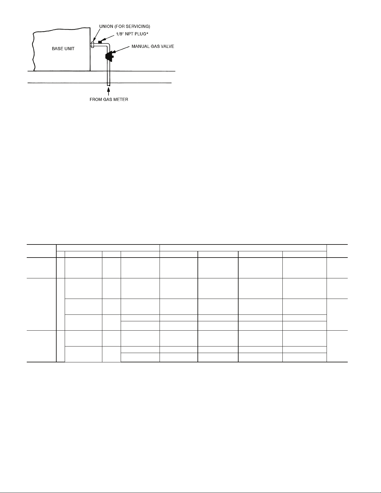
*NPT plug is field supplied.
NOTE: Follow all local codes.
Fig. 58 — Gas Piping Details
Installing Flue/Inlet Hoods — The flue and inlet
hoods are shipped in a package taped to the basepan in the fan
section. The flue (outlet) hoods are pre-assembled. The flue deflector and inlet hoods require assembly.
The hoods are located on the heating section access panel as
shown in Fig. 59 (sizes 030-050) or Fig. 60 (sizes 055-105).
See Table 18 for a list of parts used to assemble each hood and
quantities of each hood type used with each unit.
1. Remove shipping block-offs and shipping tape from all
openings in the access panel.
2. Attach flue outlet hoods (see Fig. 61) to access panel using screws provided. Hoods are placed over each combustion outlet.
3. Install flue deflector baffle inside flue deflector hood. See
Fig 62 for sizes 030-050 and 075-105 (V-type deflector).
See Fig. 63 for sizes 055-105 (curve-type deflector). Install flue deflector hood assembly over each flue outlet
hood (installed in Step 2). Observe the offset mounting
hole locations in the deflector hood flanges when attaching hood to panel (see Fig. 64). Holes in the mounting
flange must be at the bottom when attached.
4. Inlet hoods are shipped unassembled and must be assembled on the access panel (see Fig. 65). Flanges of the
hood top and sides should be placed on the inside of the
access panel openings. Install hood top and sides with
screws provided. Attach speed clips to screen and insert
screen into bottom opening of hood. Secure with 3
screws. On large inlet hoods, attach viewport cover over
opening in hood (see Fig. 66). Secure with two screws.
Supply-Air Thermistors (Staged Gas Units
Only) — Supply-air thermistors are a field-installed, factory-
provided component. Three supply-air thermistors are shipped
with staged gas units inside the heating section. Thermistor
wires must be connected to SGC in the heating section. See
Table 19. The supply-air thermistors should be located in the
supply duct with the following criteria:
• downstream of the heat exchanger cells
• equally spaced as far as possible from the heat
exchanger cells
• a duct location where none of the supply air thermistors
are within sight of the heat exchanger cells
• a duct location with good mixed supply air portion of the
unit.
Table 17 — 48Z Series Staged Gas Implementation
NO. OF
STAGES
2 stages Z H, K, W, Y 030
5 stages Z J, L, X, Z 030
9 stages Z J, L, X, Z 055
LEGEND
CAPMXSTG — Maximum Capacity per Changes
HTSTGTYP — Heat Stage Type
LIMTHIHT — Limit Switch Thermistor High Temperature
LIMTLOHT — Limit Switch Thermistor Low Temperature
MODEL NUMBER POSITION POINT
3 5 6,7,8 10 HTSTGTYP CAPMXSTG LIMTHIHT LIMTLOHT
035
040
050
035
040
050
H, K, W, Y 055
H, K 075
J, L 075
060
070
090
105
060
070
090
105
ALL Default=0 Default=45 Default=170 F Default=160 F Low
ALL Default=1 Default=20 Default=170 F Default=160 F High
ALL Default=1 Default=20 Default=135 F Default=125 F Low
-,A,B,C,D,E Default=1 Default=20 Default=135 F Default=125 F
G,H,J,K,L,M Default=1 Default=20 Default=130 F Default=120 F
ALL Default=3 Default=15 Default=135 F Default=125 F High
-,A,B,C,D,E Default=3 Default=15 Default=135 F Default=125 F
G,H,J,K,L,M Default=3 Default=15 Default=130 F Default=120 F
HEAT
SIZE
56
Page 57

INLET HOOD
FLUE HOOD AND
FLUE DEFLECTOR
HOOD (48 SERIES
HIGH-HEAT ONLY)
INLET HOOD
FLUE HOOD AND
DEFLECTOR
HOOD
INLET HOOD
Fig. 59 — Flue/Inlet Hood Locations, 030-060 Units
FLUE DEFLECTOR
PUSH
BAFFLE
DOWN SO
THESE 2
HOLES
ALIGN
BAFFLE
TOP (WHEN INSTALLED)
Fig. 62 — Flue Deflector Baffle, 030-050 and
075-105 Units (V-Type)
FLUE DEFLECTOR
HOOD
FLUE
DEFLECTOR
HOOD
FLUE AND
FLUE
DEFLECTOR
HOOD
FLUE HOOD
AND FLUE
DEFLECTOR
LARGE
INLET
HOOD
SMALL
INLET
HOOD
LARGE
INLET
HOOD
LOCATION
(
HIGH-HEAT
ONLY)
HOOD
FLUE AND
FLUE
DEFLECTOR
HOOD
LOCATION
(
HIGH-HEAT
ONLY)
Fig. 60 — Flue/Inlet Hood Locations, 055-105 Units
FLUE DEFLECTOR
BAFFLE (BOTH HOODS)
Fig. 63 — Flue Deflector Baffle, 055-105 Units
(Curve-Type)
OBSERVE OFFSET
MOUNTING HOLE
LOCATIONS WHEN
INSTALLING FLUE
DEFLECTOR HOODS.
Fig. 61 — Flue Outlet Hood
Fig. 64 — Mounting Deflector Hoods
57
Page 58

ACCESS PANEL
OPENING
COVER
(LARGE HOOD ONLY)
HOOD
VIEW PORT
COVER
SIDE (TYP
BOTH SIDES)
SPEED CLIP
(TYP 3)
Fig. 66 — Inlet Hood View Port Cover Installation
(055-105 Units Only)
Fig. 65 — Inlet Hood Assembly
Table 18 — Flue and Inlet Hood Usage
HOOD TYPE PARTS LIST FIG. NO.
Top (14-in.)
Side (Left)
Large Inlet
(14-in.)
Small Inlet
(6-in.)
Flue Outlet Pre-assembled 61 1 2 2 3 2 3
Flue Deflector
(V-Type)
Flue Deflector
(Curve-Type)
Side (Right)
Screen
Cover
Speed Clips
Screws
Top (6-in.)
Side (Left)
Side (Right)
Screen
Cover
Speed Clips
Screws
Hood
Deflector
Baffle
Screws
Hood
Deflector
Baffle
Screws
65,66 3 3 1 2 1 2
Sizes 030-050
(Low Heat)
65 — — 1 1 1 1
62 1 2 — — 2 2
63 — — 2 3 — 1
Sizes 030-050
(High Heat)
QUANTITY USED
Sizes 055-070
(Low Heat)
Sizes 055-070
(High Heat)
Sizes 075-105
(Low Heat)
Sizes 075-105
(High Heat)
58
Page 59

Table 19 — SGC Thermistor Designations
THERMISTOR
SAT1 J8 – 1,2 (SGC)
SAT2 J8 – 3,4 (SGC)
SAT3 J8 – 5,6 (SGC)
LIMTTEMP J8 – 15,16 (SGC)
SGC — Staged Gas Controller
PIN
CONNECTION
POINT
Supply-Air Thermistor (SAT) — Inserted into supply section
underneath the gas heat section (factory-provided,
field-installed)
Supply-Air Thermistor (SAT) — Inserted into supply section
underneath the gas heat section (factory-provided,
field-installed)
Supply-Air Thermistor (SAT) — Inserted into supply section
underneath the gas heat section (factory-provided,
field-installed)
Limit Switch Thermistor (LIMTTEMP) — Inserted next the
lower limit switch (factory-installed)
Install Unit Accessories — For applications requiring
accessories, the following packages are available:
All units:
• barometric relief
• space temperature sensor
•CO
• space temperature sensor with CO
sensor
2
2
• airflow switch
• filter switch
• smoke detector
All 48ZG,ZT,Z6 units:
• modulating power exhaust
• pressure operated unloaders
All 48ZN,ZW,Z8 units:
• modulating power exhaust
• VFD remote display
Refer to the individual accessory installation instructions in
each accessory package for information on installing accessories.
CONTROLS INSTALLATION
Constant Volume (CV) Units —
may be used in applications with additional control features,
options, or accessories. Refer to the appropriate accessory
installation instructions for more information on installing that
accessory. Control options and accessories available for CV
units are:
• thermostats
• enthalpy sensor
• enthalpy switch
• relative humidity sensor
• CEM (controls expansion module)
• Navigator™ hand-held display
CONTROL WIRING — The unit can be controlled with a
Carrier-approved accessory electro-mechanical or electronic
thermostat that has two stages of cooling, two stages of heating
control, and an output for fan control. The thermostat may also
include time of day scheduling or use scheduling routines built
into the ComfortLink™ controls.
Install the thermostat according to the installation instruc-
tions shipped with the accessory thermostat. Locate thermostat
assembly on a solid interior wall to sense average temperature.
Route thermostat cable or equivalent leads of colored wire
from subbase terminals through conduit into the low voltage
connections in the main control box. For thermostat TB203
connections, see Fig. 67.
NOTE: For wire runs up to 50 ft, use no. 18 AWG (American
Wire Gage) insulated wire (35 C minimum). For over 75 ft, use
no. 14 AWG insulated wire (35 C minimum). All wire larger
The 48ZG,ZT,Z6 units
FUNCTION AND LOCATION
Thermistors
PART NO .
HH79NZ033
than no. 18 AWG cannot be directly connected at the thermostat
and will require a junction box and splice at the thermostat.
Variable Air Volume (VAV) Units — The 48ZN,
ZW, Z8 units may be used in applications with additional control features, options, or accessories. Refer to the appropriate
accessory installation instructions for more information on installing that accessory. Refer to the Controls and Troubleshooting manual for more information concerning installation and
configuration of options and accessories. Control options and
accessories available for VAV units are:
• enthalpy sensor
• enthalpy switch
• relative humidity sensor
• CEM (controls expansion module)
• Navigator hand-held display
• VFD remote display
VAV CONTROL WIRING — The recommended types of
control wiring are shown below:
MANUFACTURER
Alpha 1895 —
American A21451 A48301
Belden 8205 884421
Columbia D6451 —
Manhattan M13402 M64430
Quabik 6130 —
Regular Wiring Plenum Wiring
PART NO.
SENSORS — Sensors should be wired using single twisted
pairs of 20 AWG (American Wire Gage) conductor cable rated
for the application, except for the T-56 accessory sensor which
requires 3-conductor cable.
NOTE: Humidity and CO
sensors must be powered from
2
isolated 24-v power supplies.
HUMIDITY CONTROL AND HOT WATER AND
STEAM VALVES — These devices require 20 AWG twisted
pair conductor cables rated for the application for the 4 to
20 mA signal.
SPACE TEMPERATURE SENSOR (T-55) — The space temperature sensor (P/N 33ZCT55SPT) is shipped standard with
every unit, and is located in the main control box. Space temperature sensor wires are to be connected to terminals in the
unit main control box.
CAUTION
Jumper MUST be in place between pins 1 and 3, 3 and 4
or inaccurate readings could result.
To connect the space temperature sensor, see Fig. 68.
59
Page 60

SPACE TEMPERATURE SENSOR (T-56) — The space temperature sensor (P/N 33ZCT56SPT) wires are connected to
terminals in the unit main control box.
CAUTION
Jumper MUST be in place between pins 1 and 3, 3 and 4
or inaccurate readings could result.
To connect the space temperature sensor, see Fig. 68.
COMMUNICATING SPACE TEMPERATURE SENSOR
(T-58) — The communicating space temperature sensor (P/N
33ZCT58SPT) is wired to the Carrier Comfort Network
(CCN) connections on TB202.
SPACE TEMPERATURE AVERAGING — Applications that
require averaging using multiple space temperature sensors can
be satisfied using either 4 or 9 sensors as shown in Fig. 69.
NOTE: Only Carrier sensors may be used for standard T-55
space averaging. Sensors must be used in multiples of 1, 4, and
9 only, with total sensors wiring not to exceed 1000 ft. However, space temperature reset can be accomplished with only
one sensor.
NOTE: Do not use T-56 sensors for space temperature averaging because the 5-degree offset function will not work in a
multiple sensor application.
HEAT INTERLOCK RELAY (VAV Units Only — Not Necessary For Digital Air Volume Applications) — Variable air volume (VAV) units using optimal start (morning warm-up) and/
or occupied heating require that room terminals be controlled
to the fully open position when the unit goes into Heating
mode. The HIR (heat interlock relay) function is provided for
this control. When the unit goes into Heating mode, the HIR is
energized to provide switch closure or opening (depending on
how the field-supplied power source is set up) to open the room
terminals. The field connections for the HIR are at TB201 terminals 7 and 8. See Fig. 70.
Option and Accessory Control Wiring — The Z
Series units may be used in applications with additional control
features, options, or accessories. Refer to the Controls and
Troubleshooting manual for more information concerning
installation and configuration of options and accessories.
Figures 70-80 contain wiring information on the following
features:
• heat interlock relay (Fig. 70)
• outdoor air enthalpy switch (Fig. 71)
•CO
space sensor (Fig. 72)
2
• filter status switch (Fig. 73)
• fan status switch (Fig. 74)
• space humidity sensor (Fig. 75)
• return air humidity sensor (Fig. 75)
• return air CO
sensor (Fig. 76)
2
• return air smoke detector (Fig. 77)
• smoke control — fire shutdown (Fig. 78)
• smoke control — purge (Fig. 79)
• smoke control — evacuation (Fig. 79)
• smoke control — pressurization (Fig. 79)
• CCN connections (Fig. 80)
Carrier Comfort Network (CCN) Interface — The
48ZN,ZW,Z8 units can be connected to the CCN system if desired. The communication bus wiring is supplied and installed
in the field. It consists of shielded, 3-conductor cable with shield
wire.
The system elements are connected to the communication
bus in a daisy chain arrangement. The positive pin of each
system element communication connector must be wired to the
positive pins of the system element on either side of it, the
negative pins must be wired to the negative pins, and the signal
pins must be wired to signal ground pins. Wiring connections
for the CCN system should be made at the terminal block using
the screw terminals. The board also contains an RJ14 CCN
plug that can be used to connect a Navigator™ device or field
service computer. There is also another RJ14 LEN (Local
Equipment Network) connection that is used to download software. Consult CCN Contractor’s Manual for further
information.
NOTE: Conductors and drain wire must be 20 AWG minimum
®
stranded, tinned copper. Individual conductors must be insulated with PVC, PVC/nylon, vinyl, Teflon, or polyethylene. An
aluminum/polyester 100% foil shield and an outer jacket of
PVC, PVC/nylon, chrome vinyl, or Teflon with a minimum
operating temperature range of –4 to 140 F (–20 C to 60 C) is
required. See Table 20 for cables that meet the requirements.
Table 20 — CCN Connection Approved
Shielded Cables
MANUFACTURER CABLE PART NO.
Alpha 2413 or 5463
American A22503
Belden 8772
Columbia 02525
IMPORTANT: When connecting the CCN communication bus to a system element, use a color coding system for
the entire network to simplify installation and checkout.
The following color code is recommended:
SIGNAL
TYPE
+ RED 1
GROUND WHITE 2
– BLACK 3
CCN BUS CONDUCTOR
INSULATION COLOR
COMM1 PLUG
PIN NO.
NOTE: If a cable with a different color scheme is selected, a
similar color code should be adopted for the entire network.
At each system element, the shields of its communication
bus cables must be tied together. If the communication bus is
entirely within one building, the resulting continuous field
must be connected to a ground at one point only. If the communication bus cable exits from one building and enters another,
the shields must be connected to grounds at the lightning
suppressor in each building where the cable enters or exits the
building (one point per building only).
To connect the unit to the network (Fig. 80):
1. Turn off power to the control box.
2. Cut the CCN wire and strip the ends of the red (+), white
(ground) and black (–) conductors. (If a different network
color scheme is used, substitute appropriate colors.)
3. Wire the CCN to the screw terminals on the COMM
board as follows (Fig. 80):
a. Secure the red (+) wire to CCN screw terminal +
on the COMM board.
b. Secure the white (ground) wire to CCN screw
terminal C on the COMM board.
c. Secure the black (–) wire to CCN screw terminal –
on the COMM board.
60
Page 61

d. Secure shield wire to CCN screw terminal
SHIELD on the COMM board.
IMPORTANT: A shorted CCN bus cable will prevent
some routines from running and may prevent unit from
starting. If abnormal conditions occur, unplug the connector. If conditions return to normal, check CCN connector,
and run new cable if necessary. A short in one section of
the bus can cause problems with all system elements on
the bus.
RJ14 PLUG WIRING — Units on the CCN can be monitored
from the space at the sensor through the RJ14 connector, if
desired. To wire the RJ14 connector into the CCN (Fig. 80):
IMPORTANT: The cable selected for the RJ14 connector
wiring MUST be identical to the CCN communication bus
wire used for the entire network.
1. Cut the CCN wire and strip ends of the red (+), white
(ground), and black (–) conductors. (If another wire color
scheme is used, strip ends of appropriate wires.)
2. Secure the red (+) wire to CCN screw terminal + on the
COMM board.
3. Secure the white (ground) wire to CCN screw terminal C
on the COMM board.
4. Secure the black (–) wire to CCN screw terminal – on the
COMM board.
5. Secure shield wire to CCN screw terminal SHIELD on
the COMM board.
6. Connect the other end of the communication bus cable to
the CCN communication bus.
Smoke Control Modes — Rooftop units can be used
for aid in building smoke control in the event of a building fire.
The available functions include: Fire Shutdown, Pressurization, Evacuation, and Smoke Purge. These functions are
enhanced when multiple rooftop units are used to zone a building. See Table 21 and Fig. 78 and 79.
FIRE SHUTDOWN — Fire Shutdown mode terminates all
unit operation (cooling, heating, supply fan, and power
exhaust). This mode prevents recirculation of contaminated air
back into the space. The mode will not allow admission into
the space of unsuitable outside air. See Fig. 78 for wiring.
PRESSURIZATION — Pressurization mode is intended to
keep smoke out of a zone. The factory-installed optional economizer is required for this function. Pressurization is accomplished by the following:
• opening the economizer (option)
• running the supply fan (optional inlet guide vanes open
or optional VFD at normal duct static pressure set point)
• closing the power exhaust dampers (if installed as option
or accessory)
• shutting off the power exhaust fans (if installed as option
or accessory)
This allows the space to be overpressurized relative to adja-
cent zones and prevents or slows entry of smoke into this space
from adjacent zones. See Fig. 79 for wiring.
EVACUATION — Evacuation mode removes smoke or undesirable air from interior spaces without reintroducing unsuitable air. The factory-installed optional economizer with option/
accessory power exhaust is required for this function. Evacuation is accomplished by the following:
• turning the supply fan off
• opening the economizer (option required)
• running the exhaust fans (option or accessory required)
• opening the exhaust dampers.
See Fig. 79 for wiring.
SMOKE PURGE — Smoke Purge mode removes smoke
from the interior spaces and replaces it with fresh outside air.
The factory-installed optional economizer with option/
accessory power exhaust are required for this function. Smoke
purge is accomplished by the following:
• turning supply fan on
• opening the economizer (option required)
• running the exhaust fans (option or accessory required)
• opening the exhaust dampers
See Fig. 79 for wiring.
SMOKE CONTROL INSTALLATION — Implementation of
the various smoke control modes on these units requires the installer to modify the unit wiring to add contacts (via either
manual switches or relays) that will selectively interrupt and
override standard factory control sequences. See Table 21 and
Fig. 78 and 79 for more information.
Table 21 — Smoke Control Modes
FUNCTION
Supply Fan Off On Off On
IGV/VFD† — Open/On — Open/On
Economizer Closed Open Open Open
Return Air
Damper
Exhaust
Fans
Exhaust
Damper
IGV — Inlet Guide Vane
PIC — Product Integrated Control
VAV — Variable Air Volume
VFD — Variable Frequency Drive
*Power exhaust option required for this mode.
†Applicable to VAV and PIC units with appropriate options.
1
Fire
Shutdown
Open Closed Closed Closed
Off Off On On
Closed Closed Open Open
LEGEND
FIELD SUPPLIED THERMOSTAT
Y1 Y2 W1 W2 G
RC
R
R
Y1 Y2 W1 W2 G
65432
Pressur-
ization
TB203
MODE
Evacuation*
Smoke
Purge*
Fig. 67 — Field Control Thermostat Wiring
T56- SPTT55- SPT
TH
10
C
SN
13
11
9
12
15
16
14
UNIT
TB202
T1
1
3
24
T2
5
7
8
6
Fig. 68 — T55 or T56 Wiring
61
Page 62

TB202
8
RED
9
TB202
8
9
BLK
SENSOR 1
SPACE TEMPERATURE AVERAGING (4 SENSOR APPLICATION)
SENSOR 1
SENSOR 2
SENSOR 2 SENSOR 3
SENSOR 3
SENSOR 4
NOTE: Use T55 sensor only.
SENSOR 4
SENSOR 7
SPACE TEMPERATURE AVERAGING (9 SENSOR APPLICATION)
SENSOR 5
SENSOR 8
SENSOR 6
SENSOR 9
Fig. 69 — Space Temperature Averaging Wiring
62
Page 63

Fig. 70 — Heat Interlock Relay Wiring
FIELD INSTALLED (FIELD
SUPPLIED) JUMPER WHEN
ENTHALPY SWITCH NOT USED
Fig. 71 — Outdoor Air Enthalpy Switch Wiring
RCB
J4
FILTER STATUS
Fig. 72 — CO
Space Sensor Wiring
2
Fig. 73 — Filter Status Wiring
MBB
J8
MBB
J8
63
Page 64

CEM
J6
RCB
J4
Fig. 74 — Fan Status Switch Wiring
Fig. 75 — Space and Return Air Humidity Sensor Wiring
Fig. 76 — Return Air CO
Sensor Wiring
2
64
Page 65

Fig. 77 — Return Air Smoke Detector Wiring
Fig. 78 — Fire Shutdown Wiring
MBB
J6
Fig. 79 — Purge, Evacuation, and Pressurization Wiring
65
RCB J4
Page 66

COMM
BOARD
MBB
J5
Fig. 80 — CCN Connections
66
Page 67

Page 68

Copyright 2009 Carrier Corporation
Manufacturer reserves the right to discontinue, or change at any time, specifications or designs without notice and without incurring obligations.
Catalog No. 04-53480060-01 Printed in U.S.A. Form 48Z-8SI Pg 68 4-09 Replaces: 48Z-7SI
 Loading...