

Carrier Transicold Supra 550, Transicold Supra 850, Transicold Supra 950, Transicold Supra 650, Transicold Supra 750 Operator's Manual


MANUAL
OPERATOR’S
Supra 550, 650,
750, 850 & 950
TRUCK
REFRIGERATION
UNITS

CONTENTS
Page
Unit Identification 2..........................
Safety 3....................................
Pre-Trip Inspection 4.........................
Unit Operation 6............................
Starting the Unit -- Road Operation 6...........
Starting the Unit -- Standby Operation 7........
Starting the Unit -- Manual Operation 8.........
Pretrip Check 9.............................
Changing Setpoint 10........................
Start/Stop Operation 12......................
Continuous Run Operation 14.................
Manual Defrost 15...........................
City Speed 16...............................
Function Change 17.........................
Unit Data 19................................
Alarm Display and Reset 21..................
Stopping Unit 23............................
Product Loading 24..........................
Recommended Transport Temperatures 26.....
Problems 27................................
Troubleshooting 28..........................
Relay Board 30.............................
Unit Maintenance 32.........................
Unit Maintenance Schedule 34................
Standby Operation Guidelines 39..............
Emergency Road Service 40..................

1
SUPRA OPERATOR’S MANUAL
This guide has been prepared for the operator of Carrier Transicold
diesel truck refrigeration units. It contains basic instructions for the
daily operation of the refrigeration unit as well as safety information,
troubleshooting tips, and other information that will help you to deliver the load in the best possible condition. Please take the time to
read the information contained in this booklet and refer to it whenever you have a question about the operation of your Carrier Transicold Supra unit.
Your refrigeration unit has been engineered to provide long,
trouble-free performance when it is properly operated and maintained. The checks outlined in this guide will help to minimize overthe-road problems. In addition, a comprehensive maintenance program will help to insure that the unit continues to operate reliably.
Such a maintenance program will also help to control operating
costs, increase the unit’s working life, and improve performance.
This guide is intended as an introduction to your unit and to provide
general assistance when needed. More comprehensive information can be found in the Operation and Service Manual for your unit.
This manual can be obtained from your local Carrier Transicold
dealer.
When having your unit serviced, be sure to specify genuine Carrier
Transicold replacement parts for the highest quality and best reliability.
At Carrier Transicold, we are continually working to improve the
products that we build for our customers. As a result, unit specifications may change without notice.
2
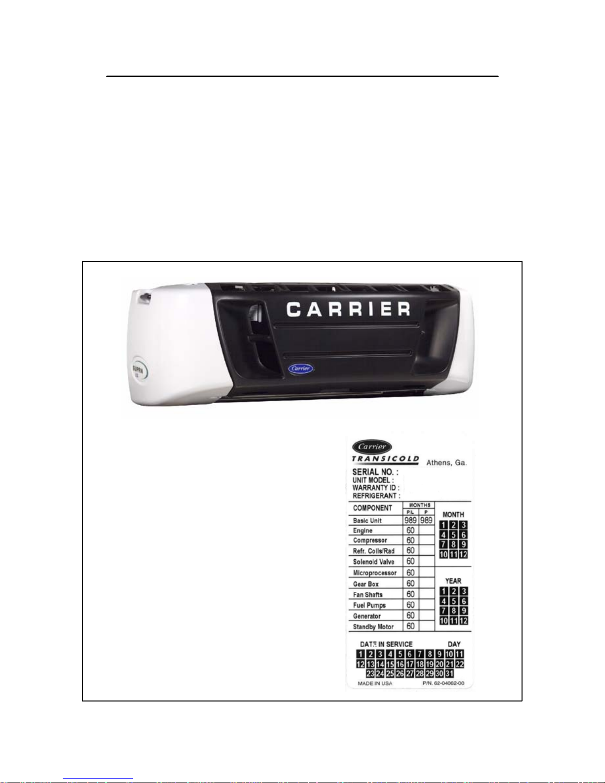
UNIT IDENTIFICATION
Each Supra 50 Series unit is identified by a nameplate attached to
the frame near the accumulator. This nameplate identifies the
complete model number of the unit, the serial number, the
refrigerant charge and quantity, and the date the unit was placed
in service.
If a problem occurs, please refer to the information on this plate,
and make a note of the model and serial number before calling for
assistance. This information will be needed when you contact a
technician or Carrier Transicold Service Engineer so that he or she
may properly assist you.
NAMEPLATE

3
SAFETY
Your Carrier Transicold refrigeration unit has been designed with
the safety of the operator in mind. During normal operation, all
moving parts are fully guarded to help prevent injury. During all
pre-trip inspections, daily inspections, and problem
troubleshooting, you may be exposed to moving parts; please stay
clear of all moving parts when the unit is in operation and when the
unit main power switch is in the RUN position.
AUTO-START/STOP
Your refrigeration unit is equipped with Auto-Start/Stop, a valuable
fuel saving feature. When the unit is set for Auto-Start/Stop
operation it may start at any time and without warning. When
performing any check of the refrigeration unit (e.g., checking the
belts, checking the oil), make certain that the main power switch is
in the OFF position.
ENGINE COOLANT
The engine is equipped with a pressurized cooling system. Under
normal operating conditions, the coolant in the engine and radiator
is under high pressure and is very hot. Contact with hot coolant can
cause severe burns. Do not remove the cap from a hot radiator. If
the cap must be removed, do so very slowly in order to release the
pressure without spray.
REFRIGERANTS
The refrigerant contained in the refrigeration system of your unit
can cause frostbite, severe burns, or blindness when in direct
contact with the skin or eyes. For this reason, and because of
legislation regarding the handling of refrigerants during system
service, we recommend that whenever your unit requires service
of the refrigeration system, you contact your nearest Carrier
Transicold authorized repair facility for service.
BATTERY
This unit utilizes a lead-acid type battery. The battery normally
vents small amounts of flammable hydrogen gas. Do not smoke
when checking the battery. A battery explosion can cause serious
physical harm and/or blindness.

4
PRE-TRIP INSPECTION
The pre-trip inspection should be performed before picking up any
load. This inspection is essential to anticipate and help minimize the
possibility of “over-the-road” problems. These checks take only a
few minutes.
1. Place the unit’s main switch in the STOP (0) position.
2. Fuel -- drain any water and impurities from the sump of the
refrigeration unit fuel tank by opening the drain-cock located on
the bottom of the tank (if so equipped). Close the valve when
only pure fuel emerges. Check the fuel level in the tank,
ensuring that the fuel supply is adequate for unit operation.
Refuel if necessary.
3. Belts -- Check the belt tension by depressing the belt with your
thumb, near the center of the longest free run of each belt.
Under moderate pressure each belt should deflect
approximately 6 mm to 13mm (1/4 inch to 1/2 inch). If the belts
deflect more than this they should be tightened (loose belts
may slip, generating heat and reducing belt life). If the belts are
too tight they should be loosened; tight belts can reduce
bearing life.
3. Battery -- on units equipped with serviceable batteries, the level
of the electrolyte in each of the cells should be checked. If the
level is low, distilled water should be added to the correct level.
Most units, however, are equipped with low or no--maintenance
batteries. These should be inspected to ensure that the
connections are clean and tight, and the battery hold--down
should be checked for tightness.

MARKS ONLY
NO WORDING
5
5. Engine Oil -- the engine oil should
be checked last since it is
necessary for oil to drain from the
block and into the oil pan to obtain
a correct reading. Remove the
dipstick, wipe it off and re-insert it
fully into the engine block. Once
again, remove the dip-stick and
observe the oil level; it should be
somewhere between the full and
add marks. If it is below the add
mark, add oil until the level is
correct.
6. Over-all Unit -- visually inspect the entire unit for leaks, loose
bolts, frayed, loose, or broken wires, etc. The radiator and
condenser coils of the unit should be free of dirt, bugs,
cardboard, or any other debris that may obstruct airflow across
the coils. The evaporator (located inside the body) should be
free of debris also, especially stretch-wrap, which is often used
during transport to prevent cargo shifting.
7. Truck body -- The body should be inspected prior to loading.
Check the door and vent seals for damage and wear. Inspect
the entire interior and exterior of the body for damage; check
for damage to the inner and outer skins of the body. Damage
to the insulation may compromise the unit’s ability to maintain
the product temperature by increasing the amount of heat gain
across the truck body.

6
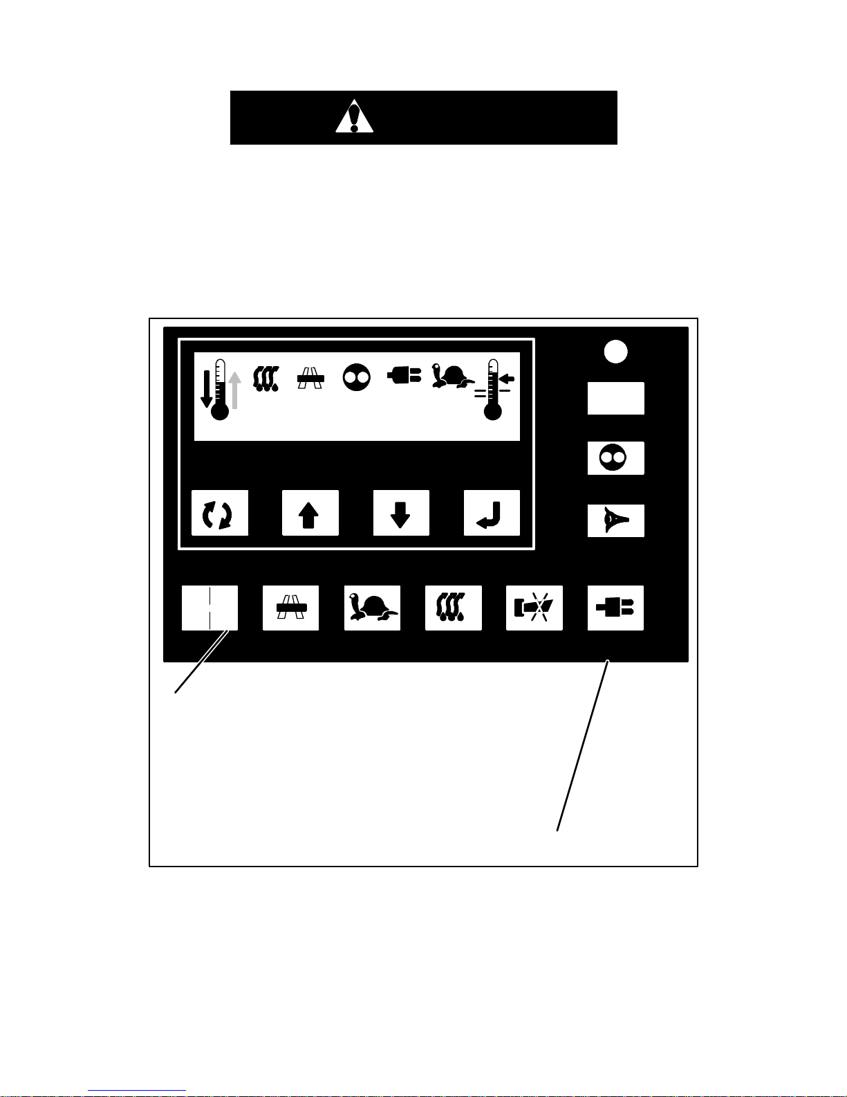
UNIT OPERATION
STARTING THE UNIT -- ROAD OPERATION
WARNING
Under no circumstances should ether or any other
starting aids be used to start engine.
BOX TEMPERATURE
AUTO START/STOP
I
UNIT DATA
PRETRIP
ALARM/FAULT
STANDBYBUZZER OFF
MAN
DEFROST
CITY
SPEED
ROAD
FUNCTION
ENTER
SETPOINT
O
i
-20 35° F
1. Place the I/O switch in the “I” position.
2. If unit was previously used in Standby
Mode, press the ROAD key.
Under normal circumstances this is all that is required to start the
unit. The unit will then perform a complete diagnostic check on the
microprocessor controller, pre-heat for the required amount of time
based on the engine temperature and start automatically.
Complete the Pre-Trip Inspection described in the previous section.
7
STARTING THE UNIT -- STANDBY OPERATION
WARNING
Make sure the power plug is clean and dry before connecting to any power source.
Do not attempt to connect or remove power plug or
perform service and/or maintenance before ensuring
the unit RUN/STOP Switch is in the STOP position and
the I/O switch is in the “O” position.
BOX TEMPERATURE
AUTO START/STOP
I
UNIT DATA
PRETRIP
ALARM/FAULT
STANDBYBUZZER OFF
MAN
DEFROST
CITY
SPEED
ROAD
FUNCTION
ENTER
SETPOINT
O
i
-20 35° F
2. Connect unit to appropriate power source.
(See table on page 39)
4. Press Standby key.
1. Place the unit RUN/STOP switch in the
“STOP” position and the I/O switch in the “O”
position.
3. Place the unit RUN/STOP switch in the
“RUN” position and the I/O switch in the “I”
position.
Under normal circumstances this is all that is required to run the unit
in standby power. The unit will then perform a complete diagnostic
check on the microprocessor controller and start automatically.
Complete the Pre-Trip Inspection described in the previous section.

8
STARTING THE UNIT -- MANUAL OPERATION
BOX TEMPERATURE
AUTO START/STOP
I
UNIT DATA
PRETRIP
ALARM/FAULT
STANDBYBUZZER OFF
MAN
DEFROST
CITY
SPEED
ROAD
FUNCTION
ENTER
SETPOINT
O
i
MAN OP
1. Place unit RUN/STOP switch in RUN and I/O switch in “I”
position. (Manual Operation will only function if unit is in
Continuous Mode. If AUTO START/STOP indictor is
illuminated, press AUTO START/STOP toggle key to
place unit in Continuous Mode.)
2. Press FUNCTION key until AUTO OP or MAN OP is
displayed. If MAN OP appears, unit is already in Manual
Start Mode.
3. If AUTO OP appears, first press
ENTER key,
then UP or DOWN arrow key until MAN OP
appears.
Press ENTER key to lock in Manual Mode.
4. Place manual GLOW/CRANK switch in
GLOW and hold for 5 to 15 seconds. Then
place switch in CRANK position to
crank and start.
Control Box

9
PRETRIP CHECK
BOX TEMPERATURE
AUTO START/STOP
I
UNIT DATA
PRETRIP
ALARM/FAULT
STANDBYBUZZER OFF
MAN
DEFROST
CITY
SPEED
ROAD
FUNCTION
ENTER
SETPOINT
O
i
PPPP
1. Start and run unit until box temperature is
40_±5°F(4.4_±2.8°C).
2. Press PRETRIP CHECK key.
The PRETRIP key initiates a check of all normal operating modes.
Upon initiation, the unit will cycle through all operating modes at 30
second intervals. The display will show “PPPP” at the beginning
and will show various unit data during the pre-trip cycle. The final
PRETRIP mode is Defrost. When Defrost ends, PRETRIP will be
complete.
This is not a self-diagnosing pretrip test. No specific pretrip alarms
will be generated. Pretrip must be monitored by the user to verify
that the unit operates through all cycles.

10
CHANGING SETPOINT
BOX TEMPERATURE
AUTO START/STOP
I
UNIT DATA
PRETRIP
ALARM/FAULT
STANDBYBUZZER OFF
MAN
DEFROST
CITY
SPEED
ROAD
FUNCTION
ENTER
SETPOINT
O
i
Press ENTER key when desired setpoint is
displayed to lock in new setpoint.
New setpoint will flash and then return to original
setpoint if ENTER key is not pressed within 5
seconds.
Press UP or DOWN arrow key to increase or
decrease displayed setpoint.
-20 35° F

11
Setpoints of -22°Fto+89°F (-30°Cto+32°C) may be entered via
the keypad. The controller always retains the last entered setpoint
in memory. If no setpoint is in memory (i.e. on initial startup), the
controller will lock out the run relay and flash “SP” on the left hand
display until a valid setpoint is entered. The setpoint may be
changed up or down in 1° increments by pressing and releasing
either the UP ARROW or DOWN ARROW key .
You cannot change setpoint when unit is in Pretrip or when viewing
Unit Data or Functional Parameters.
 Loading...