

Page 1

Minimum Load Control Accessory
Installation Instructions
Part No. 30GX-900---048,
(60 Hz — 115-v Control)
Part No. 30GX-900---049
(50 or 60 Hz — 230-v Control)
30GXN,R080-528
30HX076-271
50/60 Hz
CONTENTS
Page
SAFETY CONSIDERATIONS
INTRODUCTION
INSTALLATION
. . . . . . . . . . . . . . . . . . . . . . . . . . . . . . . . . . 1
. . . . . . . . . . . . . . . . . . . . . . . . . . . . . . . . . 1-8
Step 1 — Examine Package Contents
Step 2 — Install Piping
. . . . . . . . . . . . . . . . . . . . . . 1
. . . . . . . . . . . . 1
. . . . . . . . . . . . . . . . . . . . . . . . . . . 2
• REMOVE MINIMUM LOAD PORT PLUGS
AND INSTALL FITTINGS
• INSTALL PIPING
• INSTALL BALL AND SOLENOID VALVES
• CONNECT PIPING
• 30GXN,R UNITS ONLY
Step 3 — Dehydrate and Recharge Circuit
Step 4 — Install Control Wiring
. . . . . . . . . . . . . . . . . . . 3
. . . . . . . . 3
• 30HX UNITS
• 30GXN,R UNITS
• ALL UNITS
Step 5 — Configure Unit for Minimum
Load Control
. . . . . . . . . . . . . . . . . . . . . . . . . . . . . . . . . . . 8
Step 6 —Test Minimum Load Relay
Outputs
. . . . . . . . . . . . . . . . . . . . . . . . . . . . . . . . . . . . . . . . 8
Step 7 — Adjust Setting of Minimum
Load Ball Valve
. . . . . . . . . . . . . . . . . . . . . . . . . . . . . . . . 8
SAFETY CONSIDERATIONS
Installing, starting up, and servicing air-conditioning equip-
ment can be hazardous due to system pressures, electrical components, and equipment location.
Only trained, qualified installers and service technicians
should install, start up, and service this equipment.
When working on air-conditioning equipment, observe pre-
cautions in the literature and on tags, stickers, and labels
attached to the equipment.
Follow all safety codes. Wear safety glasses and work
gloves. Use care in handling equipment.
IMPORTANT: When removing refrigerant, use an
approved refrigerant recovery device. Do not vent refrigerant into the atmosphere.
INTRODUCTION
The minimum load control accessory allows 30HX and
30GXN,R chillers to have their capacities decreased below the
standard fully unloaded condition. The accessory provides
more precise control of leaving fluid temperature during light
load conditions.
The 30GXN,R and 30HX chillers have a dual-circuit
design. Each minimum load control accessory package contains the items required for both circuits. Because of a n automatic lead/lag feature on the chillers, the accessory should be
installed on both circuits.
INSTALLATION
Step 1 — Examine Package Contents —
age includes solenoid valves, ball valves, O-ring seal fittings,
and instructions. Examine each item. If any part is damaged or
missing, file a claim immediately with the shipper and notify
your Carrier representative. See Table 1 for accessory package
contents and field-supplied material.
Table 1 — Accessory Package Contents
and Field-Supplied Material
ACCESSORY PACKAGE
COMPONENTS
Solenoid Valve (2) EF23JX212 (2) EF23JX231
Ball Valve (2) EP71BA201 (2) EP71BA201
O-Ring Seal Fitting (4) 30GX503492 (4) 30GX503492
Tu be A s s e m b l y (2) 30GX503487 (2) 30GX503457
Tube Assembly (Condenser
Oil Separator)
FIELD SUPPLIED MATERIAL — REQUIRED PARTS
5
/8-in. OD Copper Tubing, Wiring, Conduit,
Thread Sealant, Electrical Supplies
(Ordered Separately)
ACCESSORY PART NUMBER
30GX-900---048 30GX-900---049
(2) 30HX402343 (2) 30HX402343
Pack-
Field Supplied
Be sure power to equipment is shut off before performing
maintenance or service.
Manufacturer reserves the right to discontinue, or change at any time, specifications or designs without notice and without incurring obligations.
Book 2
Ta b 5 c
PC 903 Catalog No. 533-00009 Printed in U.S.A. Form 30GX,HX-14SI Pg 1 102 7-00 Replaces: 30GX,HX-7SI
Page 2

Step 2 — Install Piping
Shut off all power to the unit, then lock out and safety-tag
all disconnects before proceeding with installation.
Remove refrigerant charge from circuits using an approved refrigerant recovery device before proceedi ng with
installatio n.
NOTE: The units have 2 circuits. Perform all of the followi ng
piping installation procedures on both A and B circuits.
REMOVE MINIMUM LOAD PORT PLUGS AND INSTALL FITTINGS — Plugs must be removed from these
ports and replaced with O-ring seal fittings. Note that plugs
were factory-installed with Loctitet 554 or equivalent
refrigerant-compatible sealant. Fittings should be installed with
similar sealant on threads.
30GXN,R
nipple on discharge line, located between oil separator and condenser. Remove plug from minimum load port on cooler shell.
See Fig. 1. Using thread sealant, install O-ring seal fitting in
minimum load port on cooler. Port on nipple in discharge line
is reserved for a brazed connection.
30HX
er shell and the condenser shell (30HXC) or oil separator
(30HXA). See Fig. 2. Using thread sealant, i nstall O-ring seal
fittings in minimum load ports.
— Cut plug end off of minimum load port braze
— Remove plugs from minimum load ports on the cool-
INSTALL PIPING — On 30GXN,R units, carefully thread the
cooler tube assemblies (P/N 30GX503487) on the O-ring seal
fittings installed in the cooler port. Do not tighten. Install fieldsupplied
5
/8-in. OD copper tubing between the tube assembly
and the brazed nipple on the discharge line.
On 30HX units, carefully thread the cooler tube assemblies
(P/N 30GX503487) and the condenser oil separator tube assembly (P/N 30HX402343) on the O-ring seal fittings installed
in the cooler and condenser/oil separator ports. Do not tighten.
Install field-supplied
5
/8-in. OD copper tubing between the
tube assemblies on the cooler shell and condenser (30HXC) or
oil separator (30HXA).
INSTALL BALL AND SOLENOID VALVES — Using good
piping practice, braze ball valve and sole noid valve into
5
/8-in.
minimum load piping. Fig. 2 shows a typical 30HX installation
and Fig. 3A and 3B show a typical 30GXN,R installation, including valve locations and orientation. Ensure that ball valve
is fully open, and that both the ball and solenoid valve are protected from excess heat during brazing process. Wrap wet
cloths around valve bodies and tube assembly locking nuts
during brazing to prevent damage to the valves and O-rings
from heat.
CONNECT PIPING — Lubricate O-rings with a light coating
of polyalphaolefin lubricant suitable for R-134a systems.
Thread tube assembly nuts onto the O-ring seal fittings until
they are finger-tight. Lightly snug the nut with a wrench;
DO NOT OVER TIGHTEN. Y ou s hould be able to feel the Oring compress on the last
1
/4-turn.
IMPORTANT: DO NOT over tighten the O-ring seal
nut. Damage will occ ur to t he se al, r esult ing in le aks.
→
102
Fig. 1 — Installing Fittings, 30GXN,R (Typical Size 080-150, 160 Shown)
2
Page 3

Fig. 2 — Installing Fittings and Valves, 30HX (Typical)
30GXN,R UNITS ONLY — Using good brazing practice,
braze the
5
/8-in. minimum load tubing to the copper nipple on
the discharge line (minimum load port) between the condenser
coil and oil separator. See Fig. 1, 3A and 3B.
Step 3 — Dehydrate and Recharge Circuit —
When piping has been completed, leak test the assembly. If
one of the O-ring seal fittings leaks, slowly tighten the O-ring
nut until the leak stops. If this does not fix the leak, the connection must be reinstalled using a new O-ring in the fitting. Contact your Carrier representative for assistance in locating these
parts.
After leak testing, evacuate, dehydrate, and recharge the circuit using an approved refrigerant recovery device. Correct
type and amount of refrigerant are listed on unit nameplate and
in base unit documentation.
Step 4 — Install Control Wiring
Be sure all power to the unit is off before proceeding. Lock
out and safety-tag all disconnects.
Wires between field-installed components and unit control
box must be enclosed in field-supplied conduit. Follow all local
codes and NEC (National Electrical Code, U.S.A.). Wire size
must be no. 16 AWG (American Wire Gage) (1.5 mm
2
) mini-
mum. See Fig. 4 and 5 for field wiring.
30HX UNITS — Remove the screws holding the right-side
access panel to the unit control box. Open the right-side access
panel.
Route wires through field-supplied conduit and attach the
conduit to the unit control box, using a suitable conduit fitting
and one of the available
7
/8-in. knockout openings. Attach the
other end of the conduit to the solenoid valve, using a suitabl e
fitting. Repeat for the other circuit. See Fig. 4.
30GXN,R UNITS —Route the field-supplied water proof conduit from the solenoid valves to the control box at the e nd of
the unit. See Fig. 4 and 5.
ALL UNITS — Using good wiring practice, connec t a white
wire from the solenoid valve on circuit A to a white wire from
the solenoid valve on circuit B. Connect both wires to TB2-9
(30HX) or TB4-2 (30GX).
Connect a pink wire to the solenoid valve on circuit A.
Connect a gray wire to the solenoid valve on circuit B. Con-
nect both the pink and gray wires to TB5-9 for all units.
Figure 4 shows the correct location of the wiring connection
points on the chiller.
3
Page 4

MINIMUM LOAD
CONTROL PORTS
CIRCUIT A (080-138)
CIRCUIT B (150, 160)
CIRCUIT B (080-138)
CIRCUIT A (150, 160)
SOLENOID VALVE (TYP)
BALL VALVE (TYP)
O-RING SEAL FITTING
AND ADAPTER (TYP)
→
O-RING SEAL
FITTING
BALL
VALV E
DETAIL C
Fig. 3A — Typical Piping and Valve Installation 30GXN,R080-178
and Associated Modular Sizes (080-150, 160 Shown)
SEE DETAIL C
SOLENOID
VALV E
FIELD INSTALLED
PIPING TO
CIRCUIT B DISCHARGE
LINE
MINIMUM LOAD PORT
CIRCUIT B
→
102
MINIMUM LOAD PORT
CIRCUIT A
FIELD INSTALLED PIPING
TO CIRCUIT A DISCHARGE LINE
Fig. 3B — Typical Piping and Valve Installation 30GXN,R204-350
and Associated Modular Sizes (204-268 Shown)
4
Page 5

30GXN,R080-178*
C —
CB —
CCP —
CLHR —
EMM —
EQUIP —
EXV —
FB —
FR —
GFI-CO —
MLC-B
CONDUIT
Contactor Compressor
Circuit Breaker
Comfort
Link™ Compressor
Protection
Cooler Heater Relay
Energy Management Module
Equipment
Electronic Expansion Valve
Fuse Block
Fan Relay
Ground Fault Interrupter Convenience Outlet
30HX076-186
LEGEND
GND —
LR —
MLC —
OPC —
PL —
PRI —
SCB —
SN —
MLC-A
CONDUIT
Ground
Loader Relay
Minimum Load Control
Oil Pump Contactor
Plug Assembly
Primary
Screw Compressor
Board
Sensor (Toroid)
SPT —
TB —
TRAN —
Suction Pressure
Transducer
Terminal Block
Transformer
Terminal Block Connection
Unmarked Splice
Factory Wiring
→
*And associated modular sizes.
Fig. 4 — Typical Minimum Load Control Wiring
5
102
Page 6

MLC-B
CONDUIT
MLC-A
CONDUIT
30HX206-271
*And associated modular sizes.
→
102
30GXN,R204-350*
Fig. 4 — Typical Minimum Load Control Wiring (cont)
6
Page 7
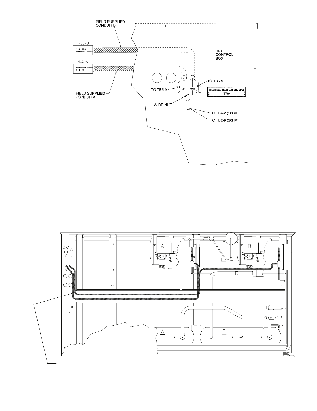
Fig. 4 — Typical Minimum Load Control Wiring (cont)
ROUTE CONDUITS THROUGH TRAY
AND ATTACH TO BOTTOM OF SHELF
ON TB-4 SIDE OF CONTROL BOX
Fig. 5 — Routing Field-Supplied Wiring and Conduit (30GXN,R Shown)
7
Page 8

Step 5 — Configure Unit for Minimum Load
Control —
tion are complete, the chiller must be configured for minimum
load control operation. This may be done using the Navigator.
Set the Enable/Off/Remote/Contact switch in the OFF position.
1. Press key until display reads ‘S ELECT A MENU
ITEM.’ Press key to light up Configuration mode.
Press . Press key to select sub-mode ‘OPT1’.
Press .
2. Press the down arrow key to select MLVS NO.
3. To enable the minimum load valve feature, press the
ENTER
4. The display may read as follows. (If not, skip to Step 7.)
ENTER P ASSWORD
5. Press 1 1 1 1 then key .
6. The Navigator again displays the following:
ML VS NO
7. Press key and key. The Navigator displays:
ML VS YES
The chiller is now configured for minimum load valve
control.
Once the piping installation and wiring installa-
ESCAPE
ENTER
ENTER
key.
ENTER
ENTER
Step 6 — Test Minimum Load Relay Outputs —
unit is recharged and reconfigured, test the operation of the relay and solenoid valve using the Service Test software function. T est both circuits as follows:
1. Press the key until the Navigator displays ‘SE-
2. The display may read as follows. (If not, skip to Step 4.)
3. Press 1 1 1 1 then key.
4. Press the down arrow key to select the ‘COMP’ sub-
5. Press the key.
After the accessory components are installed and the
ESCAPE
LECT A MENU ITEM.’ Press the key and light up
the Service Test mode. Press the key. Press the
ENTER ENTER
key and ‘TEST OFF’ will be displayed with ‘OFF’ flashing. Press the key then key and the Navigator
ENTER
displays ‘TEST ON.’ Switch the Enable/Off/Remote
contact switc h to the Enab le posit ion.
ENTER PASSWORD
ENTER
mode. Press the key and key to display MLV
ENTER
OFF.
ENTER
6. Press the and key to energize the relays. The
ENTER
display reads:
ML V ON
An audible click will be heard. Verify that the solenoid
valves for both circuits are energized.
7. Press the , and keys to turn the solenoids
ENTER ENTER
off. When finished, exit the Service Test mode (change
‘TEST ON’ to ‘TEST OFF’). Put the Enable/Off/Remote
Contact switch in the desired position.
After testing is compl ete, rechec k all e lectrical connections
for proper location and tightness. Replace and secure the access
panels for the unit control box.
Step 7 — Adjust Setting of Minimum Load Ball
Valve —
load ball valve mu st be adjusted to suit the ap plication. Calibrate one circuit at a time as follows:
1. Adjust the ball valve so that it is approximately half open.
2. Operate the chiller in Service Test mode, with one circuit
NOTE: Operation of the chiller in Manual Control mode is
described in the Controls, Start-Up, Operation, and Troubleshooting Guide that is included with the 30GXN,GXR,HX
ComfortLink™ chillers.
3. Record the cooler ∆T (the difference between cooler en-
4. Use the Service Test feature to enable the mini mum load
5. Observe and record the cooler ∆T with the minimum load
6. Adjust the minimum load ball valve until the cooler tem-
7. Open the ball valve to decrease the temperature differ-
Once the outputs have been tested and the ball valve adjusted, the ins tall ati on is co mple te.
Before the installation is complete, the minimum
operating, and all compressor loaders deenergized.
tering fluid temperature and cooler leaving fluid temperature) at this fully unloaded condition.
valve output.
valve energized.
perature difference reading from Step 5 is equal to half of
the temperature difference reading from Step 3.
ence or close the ball va lve to increase the temperature
difference (∆T). When the valve is adjusted correctly, the
difference between cooler entering and leaving fluid temperatures when the minimum load control is energized
must be at least half of the temperature difference when
the minimum load control is deenergized. For example, if
the difference between the cooler entering and leaving
water temperature is 3° F with the valve deenergized,
then the difference between cool er entering and leaving
water temperature must be at least 1.5° F with the val ve
energized.
Copyright 2000 Carrier Corporation
Manufacturer reserves the right to discontinue, or change at any time, specifications or designs without notice and without incurring obligations.
Book 2
Ta b 5 c
PC 903 Catalog No. 533-00009 Printed in U.S.A. Form 30GX,HX-14SI Pg 8 102 7-00 Replaces: 30GX,HX-7SI
 Loading...