

Carrier P5 42XPL036H3P, P5 42XPL030C3P, P5 42XPL030H3P, P5 42XPL036C3P, P5 38XPL030H3 User Manual
...Page 1
- 42XPL030C3P/38XPL030C3
- 42XPL030H3P/38XPL030H3
- 42XPL036C3P/38XPL036C3
- 42XPL036H3P/38XPL036H3
Page 2
Thank you for selecting Carrier!
You can be justifiably proud of your purchase because the same pride
in craftsmanship and engineering know-how that goes into Carrier equipment for cooling the Astrodome sports complex in Texas, the United
States Capitol’s Halls of Congress and countless other installations worldwide have been built into your unit.
One of the pleasant benefits awaiting you with room air conditioning is
that in addition to being cooled, the room air is filtered and dehumidified.
This manual is designed to help you be familiar with the many comforts
and technological features your unit offers.
Moreover, it contains vital information about maintenance, service and
economical operation. Take the next few minutes to discover for yourself
how to get the most in personal comfort and economical operation from
your new Carrier room air conditioner.
Page 3
CONTENTS
PRECAUTIONS 2
OWNER’S MANUAL
BEFORE OPERATION 5
UNIT OPERATION 9
GENERAL OPERATION
AUTOMATIC OPERATION(For Heat Pump Model)
TIMER OPERATION
COMBINATION OF ON, OFF AND DAILY TIMER
SLEEP TIMER
DISCHARGE AIR LOUVER CONTROL
AIR CLEANING OPERATION
CARE AND MAINTENANCE 17
POINTS TO NOTE
CLEANING THE FILTERS AND FRONT PANEL
CLEANING THE MAIN UNIT
AFTER-SEASON CARE
INSTALLATION MANUAL
STANDARD INSTALLATION ACCESSORIES 20
CHOOSING THE UNIT LOCATION 21
INDOOR UNIT
OUTDOOR UNIT
INSTALLATION TIPS 22
INDOOR UNIT INSTALLATION 23
INSTALLING THE WALL HANG BRACKET
MAKING THE WALL PENETRATION FOR THE INTERCONNECTING PIPING
INDOOR UNIT WIRING
FORMING THE DRAIN HOSE AND REFRIGERANT PIPING
INSTALLING THE INDOOR UNIT BODY TO THE WALL HANG BRACKET
CONNECTING THE PIPING 28
CONNECTING PIPE TO THE INDOOR UNIT
CONNECTING THE INTERCONNECTING PIPE TO THE OUTDOOR UNIT VALVE
AIR PURGE 29
USING THE VACUUM PUMP
GAS LEAK CHECK 30
FINISHING 30
OUTDOOR UNIT WIRING 31
ELECTRICAL CONNECTION 32
CONNECTING THE POWER SUPPLY 32
TEST RUNNING 33
HIGH PRESSURE CONTROL 33
CONFIGURATION 34
PUMP DOWN 35
TROUBLESHOOTING 36
Page 4
PRECAUTIONS
SAFETY CONSIDERATIONS
Installation and servicing of air conditioning equipment can be hazardous due to
system pressure and electric components. Only trained and qualified service personnel should install, repair or service air conditioning equipment.
Untrained personnel can perform basic maintenance functions of cleaning coils
and filters, and replacing filters. And untrained personnel don’t include children
and persons who with reduced physical sensory or mental capabilities, or lack
of experience and knowledge. They should have been given supervision or
instruction concerning use of the appliance by person responsible for their safety.
All other operations should be performed by trained service personnel. When
working on air conditioning equipment, observe precautions in the literature, tags
and labels attached to the unit and other safety precautions that may apply.
all safety codes. Wear glasses and work gloves. Use a quenching cloth for
Follow
brazing and detaching brazed connections. Have a fire extinguisher available for
all brazing operations.
WARNING
• Do not install by connecting them to other indoor or outdoor units without
consulting a Carrier or other competent air conditioning engineers.
Mismatching of the units and incompatibility between control devices in
the two units could lead to damage of both unit and voiding of the Carrier
warranty.
Carrier declines any responsibility, and warranty shall be void if these
installation instructions are not observed or if change are made to the
electrical connections.Contact your Carrier distributor if you need futher
help.
• Before performing service or main
off the main power switches and breaker of the unit. Electric shock may
cause personal injury. “If the supply cord is damaged. It must be replaced
with a same size BS approved cord or contact Carrier distributor to
arrange for replacement.”
tenance operations on the system, turn
CAUTION
TO DISCONNECT THE APPLIANCE FROM THE MAIN SUPPLY.
This appliance must be connected to the main by means of a circuit
breaker or a switch with a contact separation of at least 3 min.
Check that all current national safety code requirements have been followed for the installaltion. In particular ensure that a properly sized and
connected ground wire is in place.
WARNING
Do not switch off the split system by disconnecting the electric power
supply. The unit must always be switched off using the remote control.
WARNING
Check that the impedance of the mains power supply is inconformance
with the unit power input indicated in the electric data table, on page 32.
CAUTION
The mains supply must be connected to the outdoor unit.
2
2
Page 5
PRECAUTIONS
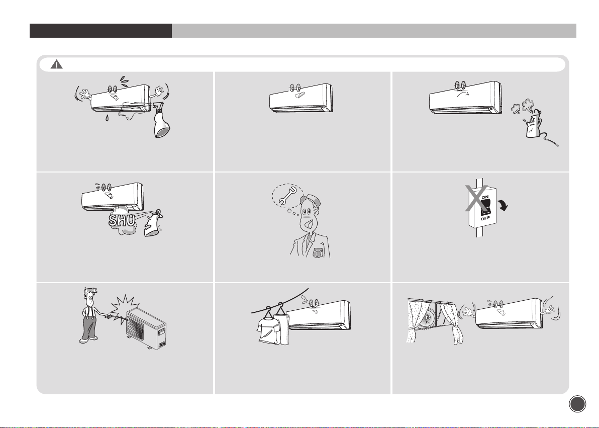
WARNING
To avoid the risk of serious electric shock,
never splash the indoor and the outdoor
unit with water.
Do not use flammable sprays near the unit.
The unit can be damaged by gasoline,
benzene, thinner,
insecticide and other chemical agents.
Do not put hands or objects into
the discharge grille of outdoor unit.
This unit has a fan running at high speed.
It is very dangerous to touch the fan.
Use the correct voltage.
Using voltage other than specified will
damage the unit.
Use only fuses of the proper amperage.
Do not obstruct the front of the discharge
grille of both units.
This will block air flow, reduce the cooling
effect and may result in unit malfunction.
Keep heat sources away from the unit,
high temperature can cause damage.
Do not use circuit breaker as a means
of turning off the unit.
The unit must always be switched off
using remote control.
In summer, if possible, prevent direct
sunlight from entering the room;
draw curtains or blinds.
3
Page 6

PRECAUTIONS
Standard Safety Instructions for Air-Conditioning Units
The air conditioner is not intended for use by young
children or special needs persons without supervision
by a person that is responsible for their safety.
Wiring connections must be secured tightly and the
cable should be routed properly to avoid the risk
Do not place the power cord near the heater
Do not touch the unit with a wet hand , there is a risk of
Electric Shock
Two or more people should lift and transport the product
and use proper Safety precautions while lifting the
product to avoid personal injury.
Young children should be supervised to ensure that they
do not play with the air conditioner.
Don’t use a damaged power cord , or loose socket as it
may cause fire or electrical shock
Install the panel and cover the control box securely
Do not place anything on the power cable , there is a
risk of fire and Electric shock
Always check for gas leakage after installation or repair
of product
4
Page 7
BEFORE OPERATION
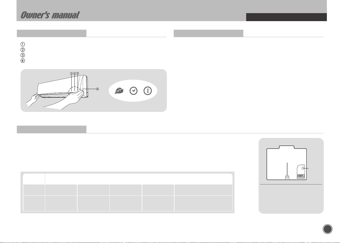
Indoor Unit Display
Ioniser(Left) light : illuminated during Ioniser activated.
Timer(Middle) light : illuminated during timer mode.
Power(Right) light : illuminated during operation.
EMER. button
Test Operation
This operation is used for checking after unit installation.
• Press the EMER. button continuously during 5~10sec. And then unit will be
operated as test mode.
• Press the EMER. button once more after checking to activate the remote
control. If there is any input signal ( remote control signal or EMER. button
press ) during test operation, the TEST mode will change to the input
signal mode.
• The setting conditions of the test operation are as follows:
- Operation mode : COOL - Fan speed : HIGH
- Timer mode : Disable - Discharge air direction : SWING
Emergency Operation
When the remote control is lost, damaged or the battery is discharged, the EMER. button can be used to run the unit.
• Press the EMER. button once briefly at the off mode condition shorter than for 5 sec.
- According to the room temperature, the unit operates the Cool mode in cool only model and the Auto mode
in Heat pump model.
• If you want to stop the emergency operation, push the EMER. button again or operate the remote control.
• The setting conditions of emergency operation are as follows:
Model Operation Preset mode Fan speed
Cooling
only
Heat
Pump
COOL 24°C AUTO Disable Horizontal
AUTO 25°C AUTO Disable
Timer mode
temperature
Discharge air direction
Preset location according
to ‘Cool’ or ‘Heat’ mode
EMER.
• EMER. button :
Can be used when the remote
control is lost or inoperative.
button
5
Page 8
BEFORE OPERATION
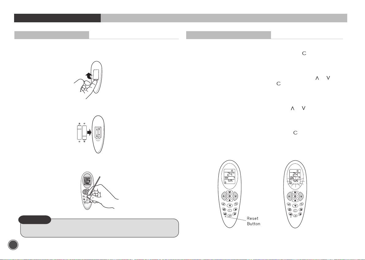
Replacing Batteries
Remove the cover of the battery compartment at the back
1
of the remote control by sliding it out in the direction of the arrow.
Remove the used batteries and insert new batteries. The remote
2
control uses two batteries.(1.5V(L)R03x2)
3
Press reset button with a sharp object if the remote control is not
operating properly or after replacing the batteries.
Setting Current Time and Reset
4
With the remote control On or OFF,
5 seconds
5
The current hour figure flashes.Press either button or to
set the current hour. Press button
set them.
For this setting always use either button or .
6
7
Once the current time is set, press button
press button for more than
to move to minutes and
to confirm it.
NOTE
• Changing batteries should be done after turning off the unit.
6
Page 9
BEFORE OPERATION
Matching Address between Indoor Unit and Remote Control
When two units are used in the same room, you can match the address of
the remote control to that of the unit.
Indoor Unit
Refer the page 35.
Remote control
Refer the page 34.
NOTE
• This function must only be performed by qualified service personnel.
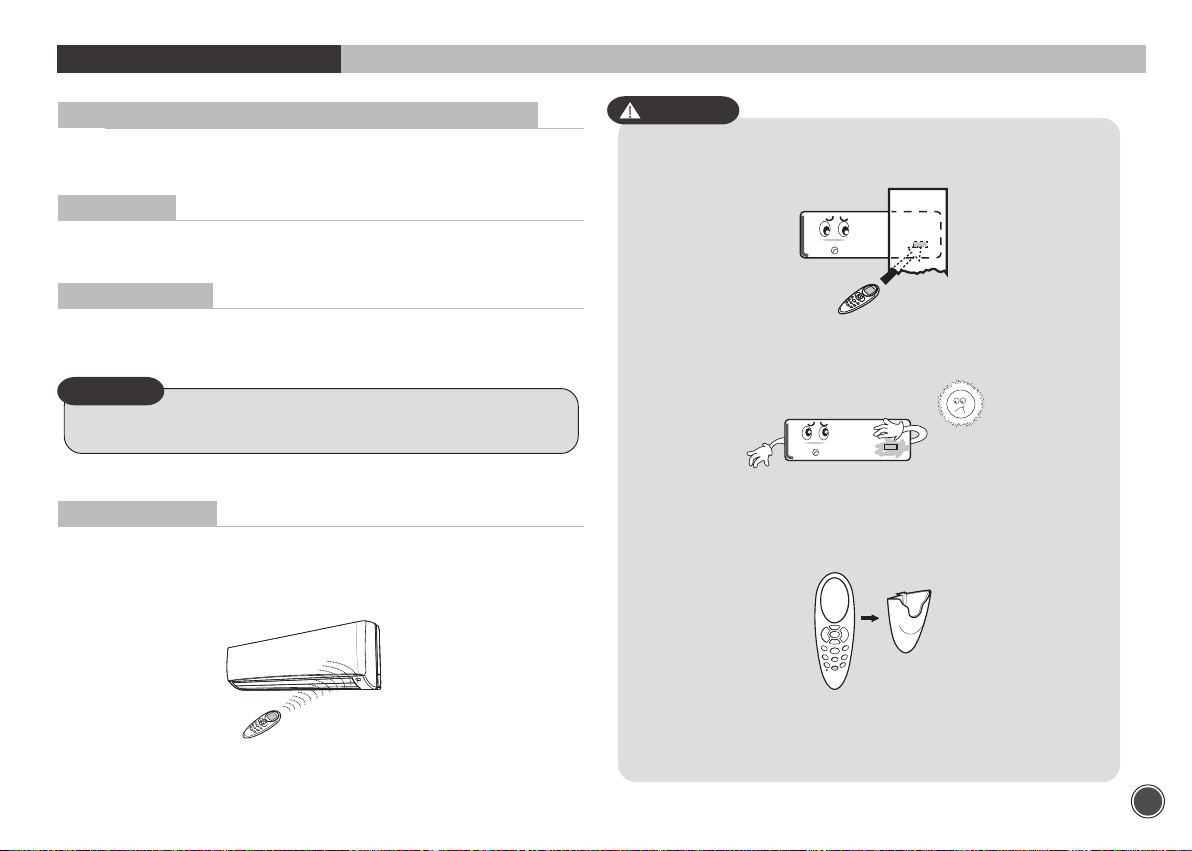
Signal Receiving
Use the remote control where its signals can reach the receiver of the air
conditioner. (A distance of 5m is allowed)
• You can hear a beep from the unit which indicates that the signal is received.
CAUTION
• The air conditioner will not operate if curtained, doors or other
materials block the signals from the remote control to the unit.
• If the infrared signal receiver on the unit is exposed to direct sunlight, the air
conditioner may not work properly. Draw the curtains to avoid direct sunlight.
• A mounting bracket for the remote control is supplied with the unit.
Install the mounting bracket on the wall where the remote signal
can be easily received from the remote.
5m maximum
• If the room using the air conditioner has florescent lighting with
electronic starter, signals may not be properly received. If you are
planning to use such fluorescent lamps, consult your local dealer.
7
Page 10
BEFORE OPERATION
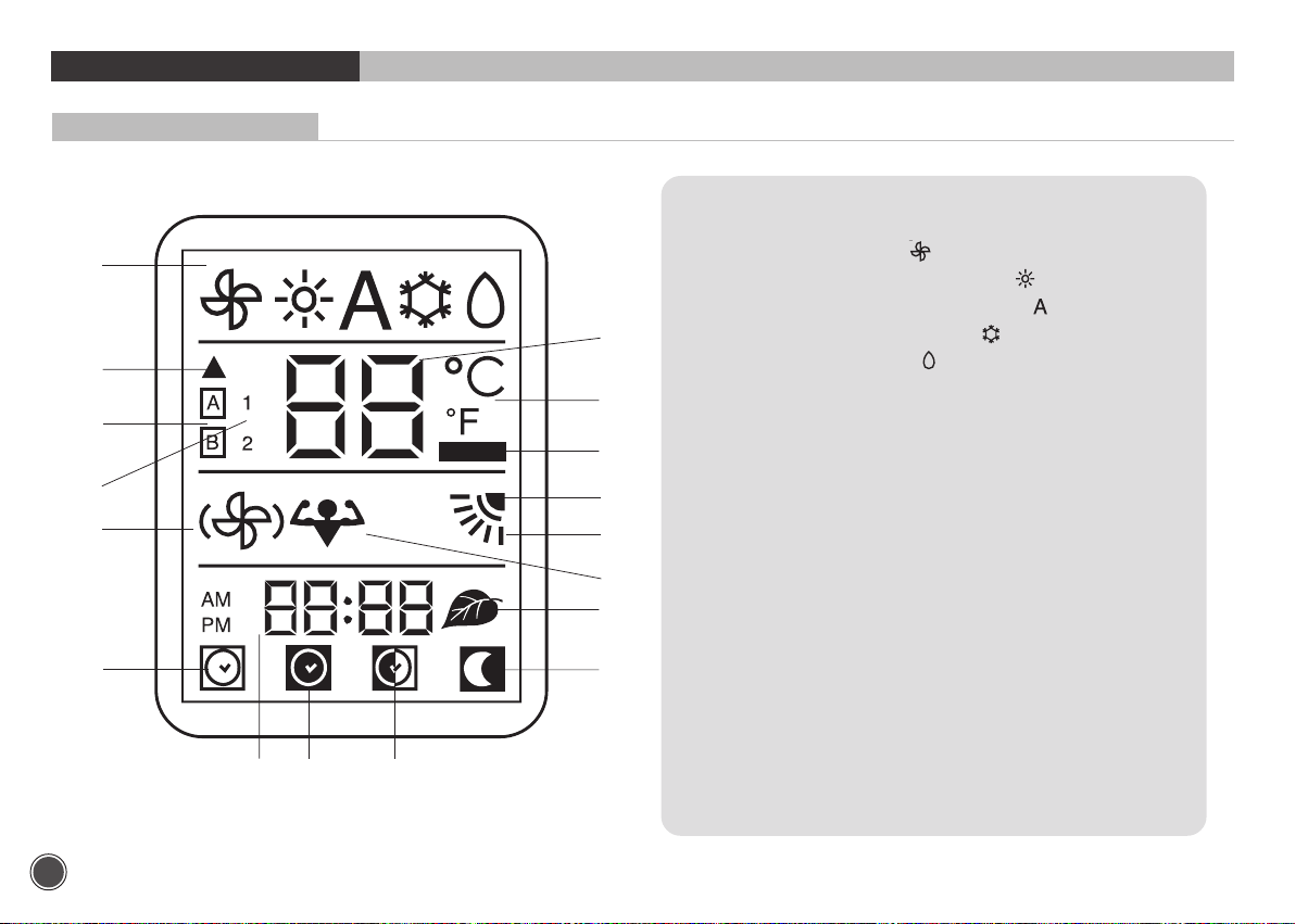
Remote Control Display
1
2
4
6
10
12
15 16 14
3
5
7
8
9
11
17
13
1. Operating mode (from left to right):
• Ventilation (fan only)
• Heating (heat pump models only)
• Automatic (heat pump models only)
• Cooling and dehumidification
• Dehumidification only
2. Signal transmission symbol
3. Temperature selected
4. Address selector
5. Temperature unit of measurement (°C or °F)
6. Unit configuration
7. Batteries exhausted indicator
8. Vertical louver swing indicator
9. Louvre positioning (Flap)
10. Fan speed
11. Turbo mode
12. ON timer selected
13. Night timer active
14. DAILY timer active (Everyday)
15. ON timer, OFF timer and current time
16. OFF timer selected
17. Ioniser active
8
Page 11
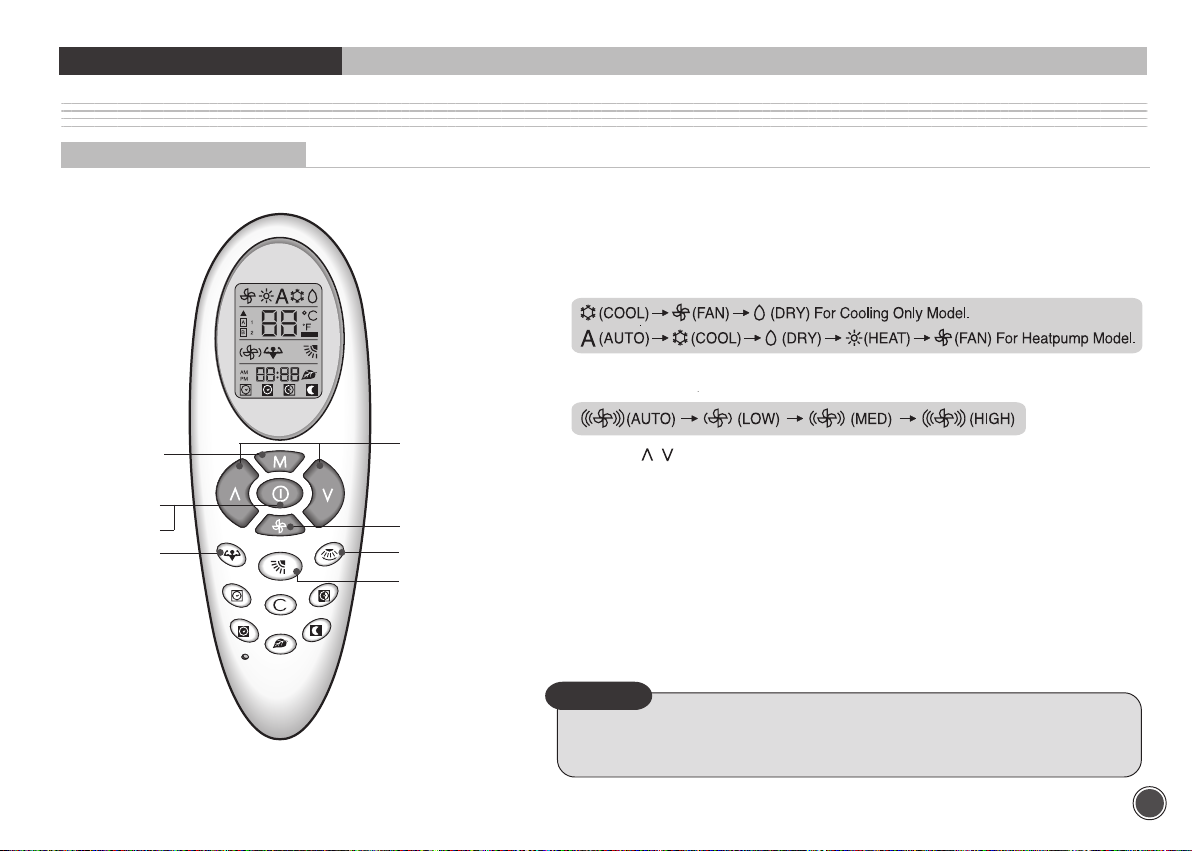
UNIT OPERATION
GENERAL OPERATION
PROCEDURE
ON/OFF button .........................................................................................................................
1
Press this button and the COOL (AUTO for Heat Pump Model) operation is indicated.
• A receiving beep is heard.
• The green UNIT ON lamp of the indoor unit display illuminates.
MODE button.............................................................................................................................
2
Press this button to select the desired operation.
3
FAN SPEED button..................................................................................................................
Press this button to select the desired fan speed.
2
4
1
7
8
3
6
5
TEMP.( ) button ...............................................................................................................
4
Press these buttons to set the desired temperature.
5
HORIZONTAL LOUVER button.......................................................................................
Press this button to control the desired air flow direction up and down.
VERTICAL LOUVER button ..............................................................................................
6
Press this button to control the desired air flow direction to the left and right side.
7
ON/OFF button
Press this button to stop the unit operation.
• A receiving beep is heard.
• The UNIT ON lamp is extinguished.
8
TURBO MODE button .........................................................................................................
Press this button to quickly cool down the indoor temperature.
NOTE
• Dry operation eliminates moisture economically by operating the compressor,
indoor and outdoor fan motor intermittently, so that the room temperature
is maintained at the set temperature.
.........................................................................................................................
9
Page 12
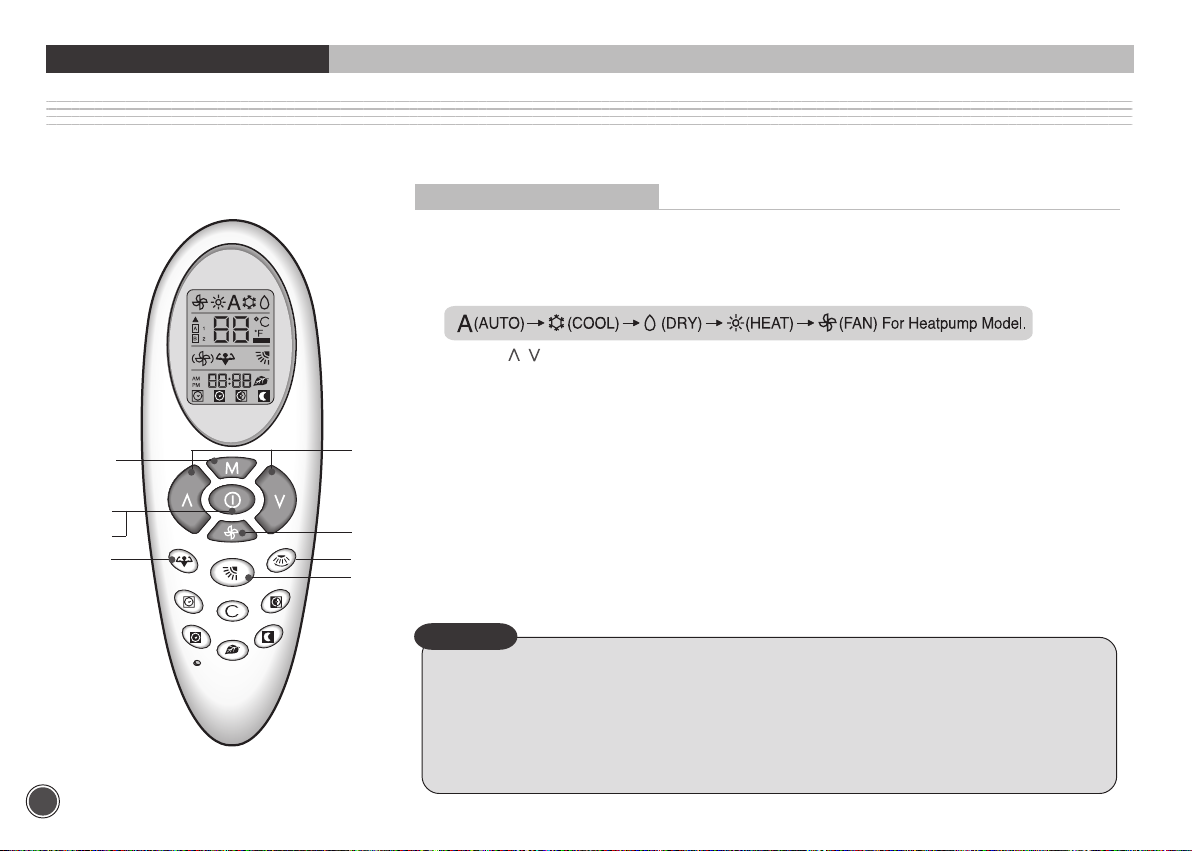
UNIT OPERATION
AUTOMATIC OPERATION (For Heat Pump Model)
Automatic operation means that the air conditioner operates automatically by selecting the COOL or HEAT mode and automatically changes the fan speed
according to the indoor condition to keep the room temperature comfortable.
PROCEDURE
ON/OFF button .......................................................................................................................................................
1
Press this button and the unit starts AUTO operation.
MODE button...........................................................................................................................................................
2
If the unit is operating in another mode, press the MODE botton to select Auto.
3
TEMP.( ) button .............................................................................................................................................
Set the desired temperature using the remote control buttons. At the start of the AUTO operation,
the temperature is set at 25°c and it is functional with in the total temperature range.
HORIZONTAL LOUVER button.....................................................................................................................
4
Press this button to control the desired air flow direction up and down.
5
VERTICAL LOUVER button ............................................................................................................................
Press this button to control the desired air flow direction to the left and right side.
FAN button ...............................................................................................................................................................
6
Set the desired fan speed. At start up, fan speed is set to AUTO.
7
ON/OFF button .......................................................................................................................................................
Press this button again to stop operation.
8
TURBO MODE button ......................................................................................................................................
Press this button to quickly cool down and heat up indoor temperature.
NOTE
• When the room temperature is between 21°c ~ 29°c.
- If the room temperature is lower 1°c or more than the set temperature : HEAT mode will be operated.
- If the room temperature is higher1°c or more than the set temperature : COOL mode will be operated.
• When the room temperature is lower than 21°c or higher than 29°c, the operation mode is restricted
regardless of the set temperature.
- If the room temperature is lower than 21°c then only the heating mode is allowed.
- If the room temperature is higher than 29°c then only the cooling mode is allowed.
• The Auto operation is not suitable for the application to the computer room or some food/wine stock storage.
10
2
3
1
7
8
6
5
4
Page 13

UNIT OPERATION
TIMER OPERATION
ON timer procedure
ON TIMER button ..........................................................
1
Press this button, even if the remote control is OFF.
The relevant icon and time figure will start to flash.
If 10 seconds have elapsed and no button is pressed,
the remote control turns OFF (if it was already OFF
when button
matically deactivates.
HOUR, MINUTE buttons(buttons and ) ............
2
If the unit is ON, the only possible selection is the
start-up time.
The unit will operate with the selections shown on the
display.
HOUR, MINUTE button(buttons and ) ..............
3
If the unit is OFF: to select the start-up time,
use the temperature control buttons
(buttons
have confirmed these by pressing button
the minutes using either button
To definitively set the time, press button
Operating mode ...............................................................
4
Choose the unit operating mode The icons will flash.
To select the mode, use the button
Once the mode has been decided, press button
The icon of the selected mode will stop flashing.
was pressed) or timer function auto-
and ). First select the hours and, after
or .
again.
.
, select
5
Desired temperature ...........................................................................................................
To select the desired temperature, the value is flashing, use either
button
Push button
6
Fan speed ..................................................................................................................................
Choose the fan speed, using button
been completed, press button
stop flashing
7
Louver positioning ...............................................................................................................
Now this icon is flashing. Use button
Press button
If you want to cancel selections up to here inserted, push button
if you want to cancel all options once timer has been set, push button
.
or .
and then .
, to confirm the selection. Numbers will stop flashing.
. When the selection has
for confirmation. The icon will
and
, to select desired position.
for confirmation. Now all icons are fixed on display.
;
11
Page 14

UNIT OPERATION
About the ON Timer
• When the ON Timer function is operating,the unit senses the room air temperature right before the start-up time.
• If you want to warm or cool the room at desired time, set the timer 30 minutes eariler than start time.
OFF timer procedure
OFF TIMER button ..........................................................................................................................................................................................
1
Press button . The OFF timer icon and numbers for time selection are flashing.This function can be set even
if the remote control is OFF.
12
HOUR/MINUTE selection button (buttons
2
To set the clock time, press either button or
To move from hour to minute, press button
NOTE
• If you reserve the ON Timer during operation, the unit will be operated continuously.
and ) .........................................................................................................................................
or .
. Press button again to confirm.
Page 15

UNIT OPERATION
Combination of ON, OFF and DAILY Timer
Procedure
DAILY timer ........................................................................................................
Push the button when the ON or OFF timer is active. The icon will appear on
display. In this way the ON and OFF timer memorization will be repeated every
day. To disactivate the daily function, press again the button
.
Combination of ON, OFF and DAILY timer procedure ...........................
If you want operation to start at 5.30 p.m. and stop at 10.30 p.m.,
proceed as follows:
1
Select ON timer at 5:30 p.m.
2
Select OFF timer at 10:30 p.m.
3
Select the desired operating mode (button
PM
PM
If you want to stop operation at 10:30 P.M. and start again at 7:30 A.M. with the
same operating mode, proceed as follows:
1
Select OFF timer at 10:30 p.m. during operation
2
Select ON timer at 7:30 A.m.
PM
AM
M
).
If you want Everyday operation to start at 5.30 p.m. and stop at 10.30 p.m., proceed
as follows:
Select ON timer at 5:30 p.m.
1
2
Select OFF timer at 10:30 p.m.
3
Press the everyday button (daily button
PM
PM
).
PM
Cancellation of ON, OFF and DAILY timer procedure ...............................................
If you want to cancel On or OFF timer setting, press the
following buttons in sequence:
1
A
B
2
PM
• button
• button .
To deactivate the Everyday function, press button
The Everyday function will remain operative until one
or
.
of the two timers (ON or OFF) is active.
NOTE
• In the ON and OFF Timer operation, the earlier setting compared to the current time will be
applied first.
• The DAILY Timer can be selected in case of a combination of the ON and OFF Timer
reservation. Daily timer is not available for sleep timer mode.
• You can change the ON/OFF reservation time during the DAILY Timer reservation.
• When the electricity fails while DAILY Timer is reserved, DAILY Timer
reservation will be canceled.
Reserve the DAILY Timer again after the electrici
• The TIMER lamp of the indoor unit will be on if either the ON Timer or the OFF Timer is
reserved.
ty comes on.
13
Page 16

UNIT OPERATION
Sleep Timer
Sleep timer procedure “night” ..........................................................................
Press this button to set the SLEEP timer with remote control on. The icon will
appear on the display.
This procedure permits setting the remaining unit operating time.
“1:hr” will be displayed together with the icon.
1
Press button (temperature increase).
2
The display will show the following settings in sequence:
1 hr, 2 hr, 3 hr, 4 hr, 5 hr, 6 hr, 7 hr, 8hr and 9 hr.
3
Once the remaining operating hours have been selected
with either button or , again press button to
confirm.
When the SLEEP timer is set, the unit will control the
4
set temperature to avoid overcooling or overheating
during operation. Also indoor fan operates at low fan
speed regardless of user selection.
The set temperature will change as follows:
NOTE
• When the SLEEP timer is set, the luminosity of the unit lamps will be dimmed
so as not to interrupt sleep.
• The SLEEP timer can be combined with the ON timer.
Turbo mode and Ioniser function
Turbo mode button
If you want more powerful capacity at Cooling and Heating mode, press
button . On the display, the powerful icon will start flashing.
During Turbo mode, you cannot control room temperature, and fan speed.
press one of the buttons or to cancel the turbo mode.
Ioniser function button ...................................................................................
....................................................................................
Turbo mode at Cooling mode
1
Performs the powerful cooling operation until room
temperature reach 17ºC or 20 minutes after pressing
turbo mode button.
At this mode, indoor fan speed is high and compressor
speed is over rating speed in order to obtain maximum
cooling capacity.
Turbo mode at Heating mode
2
Performs the powerful heating operation until room
temperature reach 32ºC or 20 minutes after pressing
turbo mode button.
At this mode, indoor fan speed is high and compressor
speed is over rating speed in order to obtain maximum
heating capacity.
Press Ioniser button to activate Ioniser function
1
during unit ON.
2
Press Ioniser button
Ioniser function.
again to stop
14
Page 17

UNIT OPERATION
DISCHARGE AIR LOUVER CONTROL
Up and Down Control
The air discharge direction can be controlled to swing up and down and can be fixed at a preferred position or at automatic position by the remote control.
CLOSE
COOL
Remote Control Auto Position
HEAT
Swing Range
HEAT
• If you select the flap position using the FLAP button in the remote control, the flap in the unit
will move to that position automatically.
Once you select the position, the unit remembers that position and whenever you turn on
the unit, the flap will be positioned to that position.
• If you select SWING, the flap will swing up and down. In the COOL, DRY and FAN mode,
the flap will swing in the cool range. In the HEAT mode, the flap will swing in the heat range.
• If you select AUTO, the flap will position itself to the preset position according to the operation mode.
Left and Right Control
If you want to adjust the direction of the discharge air left or right, Pressing the
‘vertical louver’ button. The button will set the swing on and off.
NOTE
• Please do not fix the flap at position for a long time, because this position
minimizes air circulation resulting in uneven room temperature.
• Do not adjust the flap by the hand during SWING operation because it may
damage the air swing mechanism.
• If you want maximum cooling or heating capacity, please set flap at position
Vertical louver button
.
NOTE
• Always use the remote control to adjust the flap position,
otherwise it may cause abnormal operation.
Please turn off the unit and turn it on again when you
manually adjust the flap out of range.
Horizontal Louver setting 6 and
Vertical Louver Swing Indicater
Time 1sec 1sec
Swing on
Swing off
15
Page 18

UNIT OPERATION
AIR CLEANING OPERATION
Information for filters
• Filters Standard Air Filter
Optional Filters (3 items available)
1
Active carbon filter
2
Photo catalytic filter
3
Triple filter
• Standard air filter eliminates dust and lint.
• Active carbon filter is particularly effective in eliminating odor.
• Photo catalytic filter effectively eliminates cigarette smoke in the room air.
• Triple filter (nano silver filter + vitamin filter + anti mite filter) deodorizes
ammonia, formaldehyde, toluene, and provides powerful anti-bacterial effect.
Active carbon
filter(Black)
Photo catalytic
filter(Blue)
Triple filter
(Yellow+Silver+Red)
Vitamin
Nano
Silver
Life time of filters
life of above filters varies according to the amount of air pollutant, room
• The
size and the operating time.
• Standard can be cleaned with a vacuum cleaner or rinsed under running
water after using a month.
Standard
Air filter
• The life time of Active carbon, Electrostatic, Photo-catalytic filter is
about 3 months.
Please replace them with new one every 3 months.
HOME AUTOMATION FUNCTION (optional)
• In case of fire, remote ON/OFF switching of the system is possible. In addition, the ON/OFF switching through the remote control can be locked.
• However, an adaptor and wiring connected to the central control room is necessary in the field when this function shall be feasible.
Anti mite
16
Page 19

CARE AND MAINTENANCE
POINTS TO NOTE
Operating Condition
• Temperature ran
Mode
COOL&DRY
HEAT Below 27˚C -10~24˚C -10~24˚C -10~24˚C
• When the unit operates above or below these conditions for a long time,
system diagnostics may detect a malfunction
• If the unit operates for a long time under abnormal situation of extremely high
humidity, condensed water may drip from the unit.
ges suitable for unit operation are as follows.
Indoor
(All Market)
21 ~ 32˚C 21 ~ 43˚C 21 ~ 52˚C 21 ~ 52˚C
Asia & Australia
Outdoor
Middle East Saudi Arabia
and the unit will not operate properly.
Time Delay
• If the operating mode changes from COOL and DRY to HEAT, there will be
3 minutes~3 minutes 15 sec time delay between compressor turning off
and turning on including starting the heat operation.
• If the operating mode changes from Heat to Cool and Dry, there will be
3 minutes~3 minutes 15 sec time delay .
• When heating operation starts, hot air delivery might be delayed due to
a warm up period.
Minimum Operation Time
• In normal operation, there is a minimum operation time of 3 minutes between
compressor turning on and turning off.
Defrost Operation (For Heat Pump Model)
• In the heating mode, when the outdoor coil is frosted, the indoor fan and
outdoor fan will turn off while the compressor will turn on to remove the frost
on the outdoor coil.
• The defrost mode stops after 5 minutes 20 sec or 9 minutes 40 sec according
to outdoor coil status or when compressor operates according to preset condition.
• When the power is off, the defrost operation is automatically conducted to
eliminate frost
accumulation on the outdoor coil.
Auto recovery Operation (Field selection)
• When the electricity fails while the unit is operating, the unit memorizes the
operating condition, and it will start operation automatically when the
electricity is restored.
• When you leave home during an electricity failure, please unplug the power
cord, or the unit will automatically restart in your absence.
• This function is field selectable by pressing the ‘Remote’ button upto field
requirements. Default from the factory is to have this function but it can be
selected.(Refer the page 35)
Frost Prevention of Indoor Unit
When the unit is operates at a low ambient temperature, frost may appear on
the indoor coil. When the indoor coil temperature is below 0
puter makes the compressor stop to protect the unit from frost.
º
c, the microcom-
Normal Operation
Any of the following can occur during normal operation:
• A sound like a “GURGLE” can sometimes be heard during operation or
when the unit stops.
- It is the sound of the refrigerant flowing through the unit.
• Bad smells can come
- Smells such as smoke or cosmetics can accumulate while room air
circulates through the unit.
- Cleaning the filters will reduce this problem.
• UNIT ON lamp on the indoor unit displays flashes and no air comes from the unit.
- It indicates malfunction of the unit and the compressor will stop operating.
• A “BAK-BAK” sounding noise can sometimes be heard during operation or
when the unit turns on.
- It is the sound of plastic expanding due to an abrupt temperature change.
from the unit.
17
Page 20

CARE AND MAINTENANCE
CLEANING THE FILTERS AND FRONT PANEL
Cleaning the Air Filter
1
Lift the front panel and pull the air filters
downward.
Clean the filters with a vacuum cleaner.
2
Rinse the filters under running water,
3
dry completely. and refit correctly into
their guides.
NOTE
• Turn off the unit and pull out the power plug before cleaning.
• Clean the air filters once a month.
Cleaning the Ioniser
• Clean Ioniser with a brush every three months
1) Unscrew a ioniser and open a cover
2) Rub needle on base of ioniser with brush
3) Tighten up a screw
WARNING
HIGH VOLTAGE!
The unit must be disconnected from the main supply before
maintenance or cleaning.
18
Page 21

CARE AND MAINTENANCE
Washing the Front Panel
1
Lift the front panel up to the top of the
unit and separate it from the unit.
Rinse the panel under running water
2
and dry completely in a shaded area.
Refit it correctly. Installation procedure
3
is reverse to the removal procedure.
NOTE
• Turn off the unit and pull out the power plug before washing.
• Clean the front panel if it becomes dirty and spotted.
• Front panel is removable.
CLEANING THE MAIN UNIT
• Use only a damp soapy towel.
NOTE
• When cleaning the unit, first turn it off and pull out the power plug.
AFTER-SEASON CARE
1
Clean the filters and refit them into the unit.
If the unit is to be switched off for an extended
2
period, run the unit on FAN only for two hours
to dry inside of the unit.
19
Page 22

The following installation accessories are supplied with unit. Use them as required.
Q.ty UseName and shape
STANDARD INSTALLATION ACCESSORIES
Wall hanging bracket
Screws 4xL10
Screws 3xL14
Screws 5xL25
Wirele
ss remote control
mou
The following field supplied items are required to complete the installation.
ting bracket
Electrostatic filter + photocatalytic filter +
Active carbon filter + Triple filter
1
2 F
1
14 For wall hanging bracket installation
1 For wireless remote control Installatio n
1~3
For indoor unit installation
or fixing unit and hanging bracket
For wireless remote control mounting bracket In stallatio n
For eliminating microscopic dust
and cigarette smoke, in the room air.(optional)
20
Page 23

CHOOSING THE UNIT LOCATION
1) Indoor Unit
1460mm
20cm or
more
mm043
10cm or
more
9cm or more
2m or more
2) Outdoor Unit
• Leave the space shown in Figure. 2 between the unit and any
obstruction for good air flow.
300 mm
10cm or
more
10cm or more
60cm or more
50cm
or
more
320 mm
277mm
Figure
508 mm
800 mm
600 mm
900 mm
• Leave the space shown in Figure. 1 for servicing or
removing the filter and for good air flow and for safety.
• If the room using the air conditioner has florescent
lighting with electronic starter, signals may not be
properly received. Keep the indoor unit away from
fluorescent lamp to receive the signal from remote.
CAUTION
Installation in the following places may cause
problem.
If it is unavoidable to use the unit in such places,
1
consult with your distributor.
• A place with an oily ambient.
CAUTION
Installation in the following places may cause problems.
319 mm
If it is unavoidable to use the unit in such places, consult
with your distributor.
• A place with machine oil.
• A saline place such as a seashore vicinity.
• A place with sulphur gas.
• A place where high-frequency waves are generated
by radio equipment, welders, and medical equipment.
363 mm
Figure 2
21
Page 24

INSTALLATION TIPS
The following points should be avoided.
Excessive distance between the indoor and the
outdoor unit. (Max 40m)
Kinking the connection pipes.
Dripping due to insufficient insulation of pipes.
22
Slack connections on the electrical cables for cooling only model & heat pump model.
Do not install the outdoor unit on grassy or soft
An uneven installation.
Indoor unit
Indoor unit
Max
Max
surfaces. ( Unit must be level. )
Excessive height between the indoor and the
outdoor unit. ( Max 20m )
Page 25

INDOOR UNIT INSTALLATION
• The piping can be connected to the four directions indicated by , , , .
When the piping is connected to the direction of
, or , detach the knock-
out either at the side or at the bottom of the unit. ( Fig. 3 )
Figure
3
1) Installing the Wall Hang Bracket
10cm
or more
30cm
or more
PLUMB
45cm
or more
Figure
4
• Install the wall hang bracket so that it is level. Use a plumb line if necessary.
( Figure. 4 )
• Be sure to leave the clearance spaces shown in Figure 1.
• Before installing the wall hang bracket, remove it from the unit by pushing up
marks ( ) at the bottom of the body.
• Fasten the wall hang bracket to the wall with 14 or more self-tapping screws
through the holes marked “ ” at the wall hang bracket.
•
Install the wall hang bracket so that there is no gap between the bracket and the wall.
• Check that the wall hang bracket does not move to prevent noise during
operation.
NOTE
• In case of removing the unit from the wall hang bracket after installing it
onto the wall, remove by pushing up MARKS ( ) at the bottom of
the body.
REMOVE SCREW
23
Page 26

INDOOR UNIT INSTALLATION
2) Making the Wall Penetration for the Interconnecting Piping
Rear Piping
• It is best for the piping to go through the wall behind the unit. So that the unit hides the pipes.
• For this method of installation, make a 65mm diameter hole in the wall at either point L or R. ( Figure. 5 )
50 130
5~10mm lower
Indoor side
Outdoor side
Figure
6
Side or Bottom Piping
• Remove the knock-out in the unit and pass the pipes through the wall.
• The pipe should slope downward and away from the unit to ensure good drainage.
24
Figure
5
• Drill a hole at a slope so that the outside end is lower ( 5-10mm ) than the inside
end to ensure good drainage.
• Cut the Wall Sleeve to match the wall thickness and to pass the pipe through the
hole. ( Figure. 6 )
Page 27

INDOOR UNIT INSTALLATION
3) Indoor Unit Wiring
• Lift the front panel up to the top of the unit and then it will be separated
from the unit.
• Detach the Terminal block cover and clamp wire. ( Figure. 7 )
• Connect the electrical connection cord with the screws to the terminal block
of the indoor unit as described at Figure. 8.
( Refer to the Wiring Diagram inside the Frame grille and Caution Label on the
frame grille. Caution Label is engraved on Frame grille )
• Reinstall the clamp wire and the terminal block cover with the screws
after wiring.
• Fit the front panel to the latch of the Frame grille.
Figure
7
For Cooling Only Model
For Heat Pump Model
CAUTION
• Do not connect wires when power is ON.
• The air conditioner always requires grounding. Ground the unit must be in
accordance with local codes.
• Every wire must be connected firmly. Use connection cable H07(H05, A07,
A05)RN-F 1.5mm
according to EN(IEC) 60335-2-40 and HD277.S1 standards.
• Wrong wiring causes malfunction of the unit and electric shock. Check
local electrical codes and also any specific wiring instructions or limitation.
• During installation, proceed first with refrigerant connections between in
door and outdoor units, and only then make the electrical ones; similarly,
when disassembling, disconnect the electrical wiring first and only then
open refrigerant connections.
• Unit must be installed according to applicable national installation standards.
2
, synthetic rubber insulation with Neoprene coating,
Figure
8
25
Page 28

INDOOR UNIT INSTALLATION
4) Forming the Drain Hose and Refrigerant Piping
• Drain hose and drain cap are assembled as shown in figure 9 in the factory. To do right-side(
the drain hose to right-side piping direction.(It is not necessary to exchange the location of drain hose and drain cap.)
• Tie the refrigerant pipe, the drain hose, and the electrical connection cord together.
• Form the refrigerant piping in the required direction, and bind the drain hose and the electrical connection cord together with vinyl tape.
The drain hose should be at the bottom. ( Figure. 10 )
Figure
9
• For Left Piping, fit the pipes and the wiring into the recess at the back of the unit as shown in Figure 11.
), right-botton( ) or right-back( ) piping in figure 3, draw
Figure
Figure
10
11
5) Installing the Indoor Unit Body to the Wall Hang Bracket
• Pass the pipes through the wall sleeve and then hook the indoor unit body onto the top of the wall hang bracket. ( Figure. 12 )
• For Left Piping, hang the unit onto the top of the wall hang bracket and incline the unit using a tool such as a screw
-driver set between the middle area of body and bottom right of the wall hang bracket. Connecting the pipe can be done more easily if the unit is inclined.
• Snap the marking places of the body(A, B) onto the hole of the bracket.
26
Page 29

INDOOR UNIT INSTALLATION
Wall hang
bracket
A
310 310
B
[mm]
Screw hole
• Next, check the drainage of the unit by pouring some water into the unit drain pan and ensure that the water drains out through the drain hose and
that there is no leakage from the other parts.
• After installation, if there is a significant gap between the unit and wall, it can be adjusted by securing 2 screws to the body and wall hang bracket.
Refer to the screw hole location(A, B) in Figure 12.
• Removing the frame grille ;
Hook
Detach terminal block cover by removing two screws and remove two screws from frame grille.
Pull the triangle marks located at the bottom of the frame grille and lift frame grille to the top of the unit.
NOTE
• The recommended bending of the drain
hose is shown in Figure 13.
Figure
13
Figure
12
27
Page 30

CONNECTING THE PIPING
Pay careful attention to the following points when installing the refrigerant pipes.
• Hold the pipe with one wrench while tightening the connections with a torque
• If the tightening torque is insufficient, gas will leak from the connection.
• If it is too strong, the flare will be damaged.
• Do not bend the pipe more than three times at one place.
• When extending the rolled pipe, straighten the pipe by unwinding as shown
or double-ended wrench.
wrench
Be careful not to damage the flare nut threads.
Tighten the nut with the torque shown in Table 1.
Flare nut Tightening(kgf-cm) Tourque(Nm)
6.35 mm (1/4”) 180 18
12.7 mm (1/2”) 560 55
15.88 mm (5/8”) 660 65
19.05 mm (3/4”) 1020 100
in Figure 14.
Figure
Table 1
14
1) Connecting Pipe to the Indoor Unit
a. Remove the indoor pipe flare nut. ( Check that there is no debris inside. )
b. Align the center of the flare surface, and tighten the indoor pipe union and
connection pipe flare nut with a torque wrench or double-ended wrench.
( Figure. 15 )
While aligning the center of the flare surface, tighten the nut by hand, hold the
union side with a wrench and tighten the nut according to the specified
tightening torque with a torque wrench.
Torque wrench or
double-ended wrench
Outdoor side
Figure
Indoor side
15
2) Connecting the Interconnecting Pipe to the Outdoor Unit Valve
• Repeat the procedure for flaring the tube to connect to the outdoor unit.
•
Tighten the flare nut of the connection pipe at the outdoor unit valve. ( Figure. 16 )
(Liquid pipe)
Two way valve
Interconnecting
pipework
(Gas pipe)
28
Three way valve
Figure
16
Page 31

AIR PURGE
Using the vacuum pump
For air purge, evacuate the air in the connecting pipe and indoor unit by using
vacuum pump. For details, please refer to the following procedure.
a. Connect the gauge manifold.
b. Open the low pressure valve and close the high pressure valve of the gauge
manifold completely.
c. Operate the vacuum pump during at least 20 minutes until the pressure
reaches -101Kpa (-760mm Hg).
d. Close the low pressure valve of the gauge manifold and stop the vacuum
pump operation. (If the indicator of gauge manifold is returned
within 1-2minute after stopping the vacuum pump, check the piping
connection leakage)
n both the two-way and three-way valve completely.
e. Ope
f. Close both the two-way and three-way valve caps completely.
g. Remove the gauge manifold and vacuum pump.(During the disconnection,
please be cautious not to lose any refrigerant and oil)
h. Reinstall the valve caps and service port nuts.
CAUTION
Refrigerant charging
• In case of refrigerant charging due to refrigerant leak or service refer to the nameplate on the outdoor unit.
• When the upward gas line is long, oil trap shall be installed every 10m in order to return oil to compressor.
When the connection pipe is less than 7.5m, extra amount of refrigerant per meter(If it is impossible to extract proper amount of refrigernat, please keep 7.5m piping
length by making loops or windingd for compressor reliability)
Figure
17
Connecting pipe Size Extra charge amount Example for 14.5m pipe
ø15.88mm 45 g/m (14.5 _ 7.5) x 45 = 315 g
ø19.05mm 60 g/m (14.5 _ 7.5) x 60 = 420 g
Note that the shorter connection pipe, the better the performance of system.
The maximum allowable length of the connection pipe is 40m and the maximum allowable elevation between indoor unit and outdoor unit should be less than 20m.
29
Page 32

GAS LEAK CHECK
After connecting the pipe, check the joints for gas leakage with gas leak detector or soapy water.
FINISHING
• Wrap the piping joints with the pipe insulation and fasten it with vinyl tape. ( Figure. 18, 19)
• Fill the gap between the inside of wall sleeve and the pipe with a sealer so that rain and wind does not enter. ( Figure. 20 )
30
Pipe
Pipe insulation
(Vinyl tape)
Figure
Pipe
Saddle
18
Figure
19
Wall sleeve
Indoor side
Wall
Wall cap
Sealer(Putty)
Outdoor side
Figure
20
Page 33

OUTDOOR UNIT WIRING
• Remove the service cover of the outdoor unit, and connect the end of the connection cord with screws to the terminal block. (
Refer to wiring diagram inside
the top cover and caution label on the service cover)
• When connections are completed, fasten the connection cord with the cable clamp and reinstall the service cover. ( Figure. 21 )
For Cooling Only Model
Terminal block
Ground screw
Cable clamp
Main power connection(L,N, )
Interconnection wire( ,R,C,Y)
Interconnection wire for Heatpump(O,W2,S)
For Heat Pump Model
Terminal block
Ground screw
Cable clamp
NOTE
• The air conditioner always requires grouding.
• Be sure to comply with local codes on running the wire from the indoor unit to the outdoor unit.
• Every wire must be connected firmly.
• During installation, proceed first with refrigerant connections between indoor and outdoor units, and only then
2
make the electrical ones;similarly, when disassembling, disconnect the electrical wiring first and only then open refrigerant connections.
• Unit must be installed according to applicable national installation standards.
Figure
21
31
Page 34

ELECTRICAL CONNECTION
For Cooling Only Model
CONNECTING THE POWER SUPPLY
• The mains supply must be connected to the outdoor unit.
Model
38XPL030C3
38XPL036C3
38XPL030H3
38XPL036H3
Phase
60Hz
60Hz
60Hz
60Hz
Starting
current
A
77
80
77
80
For Heat Pump Model
Main power
connection
Fuse
A
30
40
30
40
Wiresize
mm
4.0
4.0
4.0
4.0
size
n
OW2S
mm
1.0
1.0
1.0
1.0
2
Interconnectio
wire
2
RCY
mm
1.0
1.0
1.0
1.0
2
32
Page 35

TEST RUNNING
• Perform the operating test after the units have been installed in position and the gas leak test
has been completed.
• Check all electrical connections(instructions and wiring diagram).
• Insert the batteries into the remote control and leave it OFF.
• Energise the system, turning the power supply ON.
• Press the
than 5 seconds. The display will be cleared, the time segments will display the icon(Src=service
test)
When test mode is selected, the unit operates as described below:
• The green LED and the orange LED blink every 2 seconds.
• The indoor fan operates at low speed.
• The louver operates according to “Auto heat” or “Auto cool” based on operating mode.
• The system works in Cool Mode at fixed compressor frequency for 3 minutes.
• The system works in Cool Mode until Test Mode is exited.
During the cool mode and heat mode check the following conditions:
1. Difference between indoor ambient temperature and indoor unit air discharge temperature
must be greater than 3°C.
2. Indoor
3. Louver must be in auto heat or cool louver based on operating mode.
4. No fault code must be signalled by the system.
If one of the above conditions is not positive, please check the correct installation of the system.
• After test has been completed. press button
and buttons of the infrared remote control and hold them pressed for more
fan must operate at low speed.
on the remote control to leave the test menu.
NOTE
When 30 minutes have elapsed and no buttons have been pressed,
the remote control will automatically exit the test menu and resume its normal operation.
HIGH PRESSURE CONTROL
Unit for Middle East has high pressure switch to prevent head pressure from being out of limit due to high ambient.
If “High pressure switch” trips, cycle the power supply OFF and ON to reset the system, because electrical box is equipped with relay that prevent the unit from
starting, till the indoor unit is switched OFF.
When head pressure drops below 23bar, it is possible to restart the unit switching the indoor control ON.
33
Page 36

CONFIGURATION
Remote Control Configuration
• Remote Control is used for heat pump type air conditioner and cool only type
air conditioner.
Before user operates air conditioner, thus, cool only type and heat pump
type of remote configuration and other items must be selected as follows.
Press the and buttons of the infrared remote controller
1
and hold them pressed for more than 5 seconds.
The display will be cleared, the temperature segments will
2
display the first configuration item (CH = remote address) and
the time segments will display the default value of this
configuration item (Ab = control of both indoor units).
34
Press either the
3
(A) to the new value (b).
Press
4
5
Press either the
temperatures in Degrees Celsius (C) to the new value
Degrees Fahrenheit (
Press
6
7
Press either the
Heat pump in model type (HP) to new value cooling only
type(co).
8
Press
9
Press either the
Maximum heating setpoint or minimum cooling setpont.
Press
10
button repeatedly until “tU” is displayed.
button repeatedly until “rc” is displayed.
button repeatedly until “HR” or “CR” is displayed.
button repeatedly until “CL” is displayed.
or button to change the default value
or button to change the default value of
o
F).
or button to change the default value of
or button to change the default value of
Press either the or button to change the default value of
11
time format as AM/PM (12) to the new value of 24 hours time
format (24).
LOOK OUT! Whichever configuration value changed must
12
be confirmed pressing
13
Press
NOTE
When 30 seconds have elapsed and no buttons have been pressed, the
remote controller will automatically exit the configuration menu and the
procedure has to be restarted.
Confirguration item Value Description
button to leave the configuration menu.
"CH"
"tU"
"rc"
"HR"
"CR"
"CL"
A : Channel A Remote ID selection
Ab : Channel A and B
b : Channel B
C : Degrees C Temperature units
F : Degrees F Defaults to C
HP : Normal Operation Puts the Remote into
CO : Cooling Only Cooling Only Mode
17-32 : 17°~32°C Maximum heating setpoint
63-90 : 63°~90°F Degrees C or F is determined
17-32 : 17°~32°C Minimum cooling setpoint
63-90 : 63°~90°F Degrees C or F is determined
12 : 12 Hour Standard Time Format
(AM/PM) Defaults to 12
24 : 24 Hour Military
button each time.
Defaults to A
Defaults to HP
by “tU”configuration above
by “tU” configuration above
Page 37

CONFIGURATION
If you are installing two indoor units in the same room and you want them to operate in independent mode. It is necessary to assign each unit its own address so that
each unit can operate via its own remote control. For configuration, proceed as follows.
Unit configuration
• Press the and buttons of the infrared remote control and hold them pressed for more than 5 seconds.
• The display will be cleared, the time segments will display the first configuration item (rAdr=remote address) and the temperature segments will display the de
fault value of this configuration item(Ab=control of both indoor units).
• Press either the
• Press button repeatedly until “ZONE” is displayed.
• Press either the or button to change the default value of Zone number (0) to the new value(0-240).
• Press button repeatedly to configure Auto recovery function until “A St” is displayed.
• Press either the or button to change the default value of auto restart in last mode(On) to the new value of start in OFF mode(OF).
• LOOK OUT! Whichever configuration value changed must be transmitted to the indoor unit pressing button each time.
• Press button to leave the configuration menu.
NOTE
When 30 seconds have elapsed and no buttons have been pressed, the
remote control will automatically exit the configuration menu and the procedure has to be restarted.
or button to change the default value (Ab) to the new value (A) or (b).
PUMP DOWN
Pump down means collecting all the refrigerant in the system back into the outdoor unit without losing any refrigerant gas.
Pump down is used when the unit is moved or for servicing the refrigerant circuit.
• Close three-way valve halfway.
• Close two-way valve all the way.
• Turn the unit on for approximately 3 minutes in cooling mode.
• Close three-way valve all the way.
35
Page 38

TROUBLESHOOTING
Trouble Check Points Action
Check that the power cord is plugged Insert the power cord into the wall outlet.
into the wall outlet.
Unit does not Has the circuit breaker tripped or has the Reset the circuit breaker or replace the
operate fuse blown? fuse with the specified replacement fuse.
Has there been a power failure? Restart operation when power is resumed.
Does the “UNIT ON” lamp flash on and off? Call your service representative.
Is the voltage too low? Confirm the available voltage.
Is the filter blocked with dust? Clean the air filter.
Has the temperature been set properly? Check and reset it if necessary.
Cooling is Are the windows or doors open? Close the windows and doors.
abnormally low.
Heating is Has the temperature been set too low? Check and reset it if necessary.
abnormally low.
Unit stops during
operation. Has the room temperature reached the
If the above actions do not correct the operation, consult the dealer from whom you bought the unit.
Is anything obstructing the outdoor unit? Remove the obstruction.
Is the fan speed too low? Change the fan speed selection.
Is the operation mode FAN or AUTO?
Is the filter blocked with dust? Clean the air filter.
Are the windows or doors open? Close the windows and doors.
Is anything obstructing the outdoor unit? Remove the obstruction.
Is the OFF timer operating? Restart operation.
set temperature?
Change to cooling operation or reset the
temperature.
Normal operation.
36
Page 39

MODEL NO.
INDOOR
OUTDOOR
ELECTRICITY
COOL
CAPACITY
(Btu/h)
HEAT (W)
COOL
INPUT POWER
(kW)
HEAT
COOL
CURRENT
(A)
EER
HEAT
COOL
(Btu/hW)
COP (W/W)
DIMENSION
(MM)
WEIGHT
(KG)
HEAT
(R22) 1.95kg 2.5kg2.2kg 2.2kgREFRIGERANT
INDOOR
OUTDOOR
INDOOR
OUTDOOR
ANNUAL ENERGY CONSUMPTION
(KWH PER YEAR)
COUNTRY OF ORIGIN
(T1)
(T3)
(T1)
(T3)
(T1)
(T3)
(T1)
(T3)
42XPL030C3P
38XPL030C3
42XPL030H3P
38XPL030H3
42XPL036C3P
38XPL036C3
230V - 60Hz - 1Ph
28500
25000
-
2.26
2.70
-
9.9
11.9
-
12.61
9.26
-
1460*340*277
900*820*320
23
51
6102 6102 7128 7128
27000
24000
8000 - 9400
2.26
2.70
2.15
9.9
11.9
9.4
11.95
8.89
3.72
1460*340*277
900*820*320
23
58
32500
28500
2.64
3.19
-
11.7
14.1
-
12.31
8.93
-
1460*340*277
900*820*320
23
54
MADE IN KOREA
42XPL036H3P
38XPL036H3
31500
28000
2.64
3.19
2.66
11.7
14.1
11.8
11.93
8.78
3.53
1460*340*277
900*820*320
23
61
37
Page 40

P/N: 42KHC554040-R
 Loading...