


Carrier P1 Plus series, P2 Plus series Owners And Installation Manual


Thank you for selecting Carrier!
You can be justifiably proud of your purchase because the same pride
in craftsmanship and engineering know-how that goes into Carrier equipment for cooling the Astrodome sports complex in Texas, the United
States Capitol’s Halls of Congress and countless other installations worldwide have been built into your unit.
One of the pleasant benefits awaiting you with room air conditioning is
that in addition to being cooled, the room air is filtered and dehumidified.
This manual is designed to help you be familiar with the many comforts
and technological features your unit offers.
Moreover, it contains vital information about maintenance, service and
economical operation. Take the next few minutes to discover for yourself
how to get the most in personal comfort and economical operation from
your new Carrier room air conditioner.
42KH5A54020_O 2004.6.11, 3:6 PMPage 1 Adobe PageMaker 6.5K/PPC
PRECAUTIONS 2
BEFORE OPERATION 5
UNIT OPERATION 10
○○○○○○○○○○○○○○○○○○○○○○○○○○○○○○○○
GENERAL OPERATION
○○○○○○○○○○○○○○○○○○○○○○○○○○○○○○○○
AUTOMATIC OPERATION(For Heat Pump Model)
○○○○○○○○○○○○○○○○○○○○○○○○○○○○○○○○
TIMER OPERATION
○○○○○○○○○○○○○○○○○○○○○○○○○○○○○○○○
COMBINATION OF ON, OFF AND DAILY TIMER
○○○○○○○○○○○○○○○○○○○○○○○○○○○○○○○○
SLEEP TIMER
○○○○○○○○○○○○○○○○○○○○○○○○○○○○○○○○
DISCHARGE AIR LOUVER CONTROL
○○○○○○○○○○○○○○○○○○○○○○○○○○○○○○○○
AIR CLEANING OPERATION
CARE AND MAINTENANCE 18
○○○○○○○○○○○○○○○○○○○○○○○○○○○○○○○○
POINTS TO NOTE
○○○○○○○○○○○○○○○○○○○○○○○○○○○○○○○○
CLEANING THE FILTERS AND FRONT PANEL
○○○○○○○○○○○○○○○○○○○○○○○○○○○○○○○○
CLEANING THE MAIN UNIT
○○○○○○○○○○○○○○○○○○○○○○○○○○○○○○○○
AFTER-SEASON CARE
INSTALLATION TIPS 23
INDOOR UNIT INSTALLATION 24
○○○○○○○○○○○○○○○○○○○○○○○○○○○○○○○○
INSTALLING THE W ALL HANG BRACKET
○○○○○○○○○○○○○○○○○○○○○○○○○○○○○○○○
MAKING THE WALL PENETRATION FOR THE INTERCONNECTING PIPING
○○○○○○○○○○○○○○○○○○○○○○○○○○○○○○○○
INDOOR UNIT WIRING
○○○○○○○○○○○○○○○○○○○○○○○○○○○○○○○○
FORMING THE DRAIN HOSE AND REFRIGERANT PIPING
○○○○○○○○○○○○○○○○○○○○○○○○○○○○○○○○
INSTALLING THE INDOOR UNIT BODY TO THE WALL HANG BRACKET
CONNECTING THE PIPING 29
○○○○○○○○○○○○○○○○○○○○○○○○○○○○○○○○
CONNECTING PIPE TO THE INDOOR UNIT
○○○○○○○○○○○○○○○○○○○○○○○○○○○○○○○○
CONNECTING THE INTERCONNECTING PIPE TO THE OUTDOOR UNIT VALVE
AIR PURGE 30
○○○○○○○○○○○○○○○○○○○○○○○○○○○○○○○○
USING THE VACUUM PUMP
GAS LEAK CHECK 31
FINISHING 31
OUTDOOR UNIT WIRING 32
ELECTRICAL CONNECTION 33
CONNECTING THE POWER SUPPLY 33
TEST RUNNING 34
AUTO RECOVERY OPERATION - FIELD SELECTION 34
PUMP DOWN 35
ADDRESS SWITCHES 35
TROUBLESHOOTING 36
OWNER’S MANUAL
INSTALLATION MANUAL
Chargeless
• No additional refrigerant required.
NOTE
STANDARD INSTALLATION ACCESSORIES 21
CHOOSING THE UNIT LOCATION 22
○○○○○○○○○○○○○○○○○○○○○○○○○○○○○○○○
INDOOR UNIT
○○○○○○○○○○○○○○○○○○○○○○○○○○○○○○○○
OUTDOOR UNIT
CONTENTS
42KH5A54020_O 2004.6.17, 11:25 AMPage 23 Adobe PageMaker 6.5K/PPC

2
PRECAUTIONS
Installation and servicing of air conditioning equipment can be hazardous due to
system pressure and electric components. Only trained and qualified service personnel should install, repair or service air conditioning equipment.
Untrained personnel can perform basic maintenance functions of cleaning coils
and filters, and replacing filters.
All other operations should be performed by trained service personnel. When
working on air conditioning equipment, observe precautions in the literature, tags
and labels attached to the unit and other safety precautions that may apply.
Follow all safety codes. Wear glasses and work gloves. Use a quenching cloth for
brazing and detaching brazed connections. Have a fire extinguisher available for
all brazing operations.
SAFETY CONSIDERATIONS
• Do not install by connecting them to other indoor or outdoor units without
consulting a Carrier or other competent air conditioning engineers.
Mismatching of the units and incompatibility between control devices in
the two units could lead to damage of both unit and voiding of the Carrier
warranty.
Carrier declines any responsibility, and warranty shall be void if these
installation instructions are not observed or if change are made to the
electrical connections.Contact your Carrier distributor if you need futher
help.
• Before performing service or maintenance operations on the system, turn
off the main power switches and breaker of the unit. Electric shock may
cause personal injury. “If the supply cord is damaged. It must be replaced
with a same size BS approved cord or contact Carrier distributor to
arrange for replacement.”
WARNING
TO DISCONNECT THE APPLIANCE FROM THE MAIN SUPPLY.
This appliance must be connected to the main by means of a circuit
breaker or a switch with a contact separation of at least 3 min.
If this is not possible, a power supply plug with earth must be used. This
plug must be easily accessible after installation. The plug must be disconnected from the power supply socket in order to disconnect the appliance completely from the main. The appliance must be positioned so
that the plug is accessible.
Check that all current national safety code requirements have been followed for the installaltion. In particular ensure that a properly sized and
connected ground wire is in place.
CAUTION
Do not switch off the split system by disconnecting the electric power
supply. The unit must always be switched off using the remote control.
WARNING
42KH5A54020_O 2004.6.11, 3:6 PMPage 2 Adobe PageMaker 6.5K/PPC
3
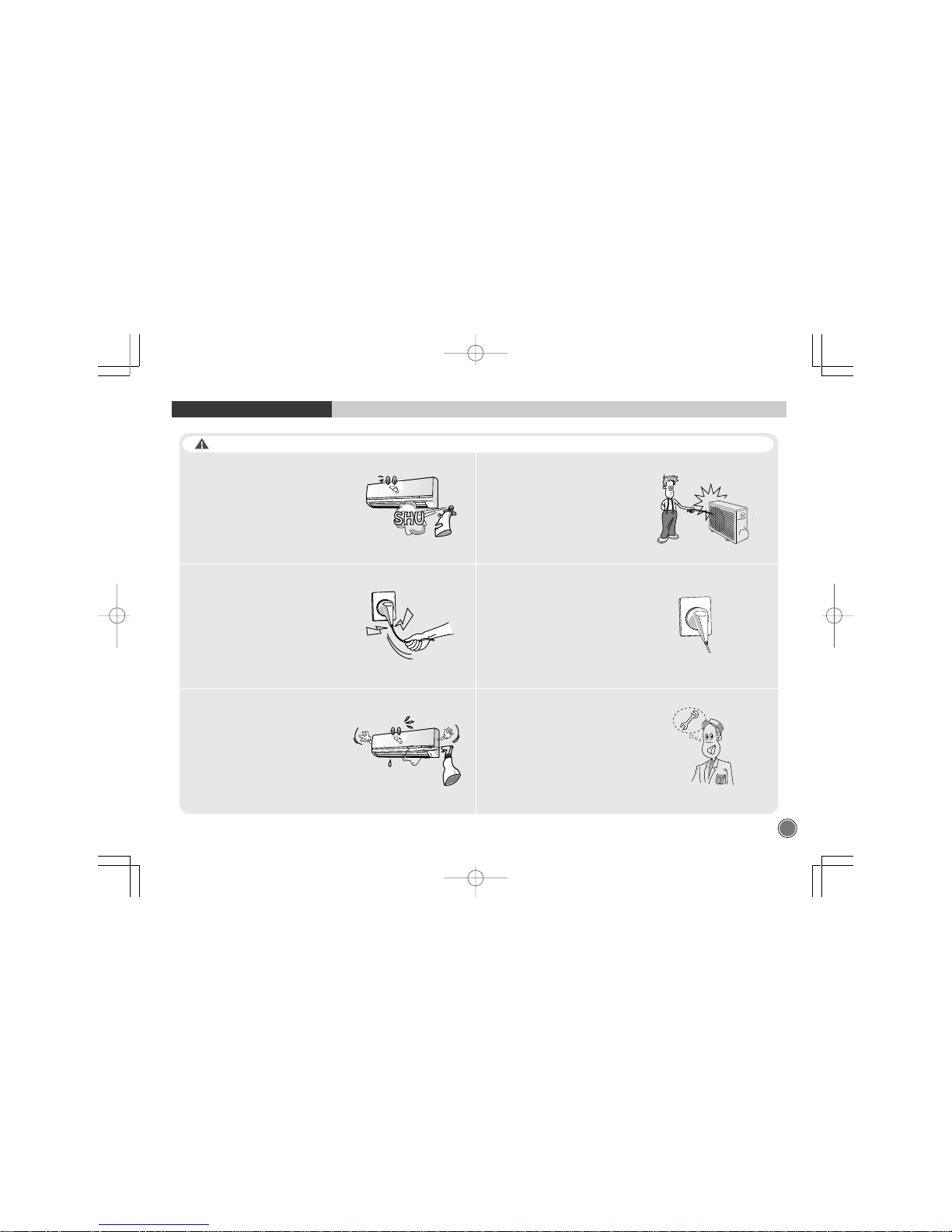
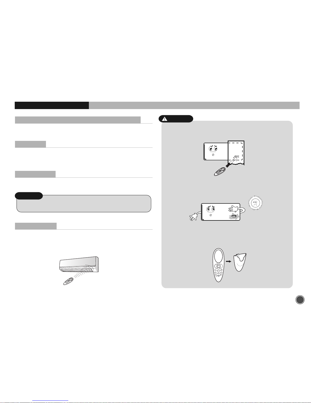
Do not use flammable sprays near the unit.
The unit can be damaged by gasoline,
benzene, thinner,
insecticide and other chemical agents.
When unplugging the power plug,
do not pull by the power cord.
The power cord will get damaged
and it can cause electric shock.
To avoid the risk of serious electric shock,
never splash the indoor and the outdoor
unit with water.
Do not put hands or objects into
the discharge grille of outdoor unit.
This unit has a fan running at high speed.
It is very dangerous to touch the fan.
Check the power plug.
If the power plug is not inserted tightly, or
if there is any damage to the power cord,
it could result in leakage or electric shock.
Use only fuses of the proper amperage.
PRECAUTIONS
WARNING
42KH5A54020_O 2004.6.11, 3:6 PMPage 3 Adobe PageMaker 6.5K/PPC

4
PRECAUTIONS
Do not obstruct the front of the discharge
grille of both units.
This will block air flow, reduce the cooling
effect and may result in unit malfunction.
Keep heat sources away from the unit,
high temperature can cause damage.
In summer, if possible, prevent direct
sunlight from entering the room;
draw curtains or blinds.
Use the correct voltage.
Using voltage other than specified will
damage the unit.
Do not use the power cord as a means
of turning off the unit.
WARNING
42KH5A54020_O 2004.6.11, 3:6 PMPage 4 Adobe PageMaker 6.5K/PPC
5
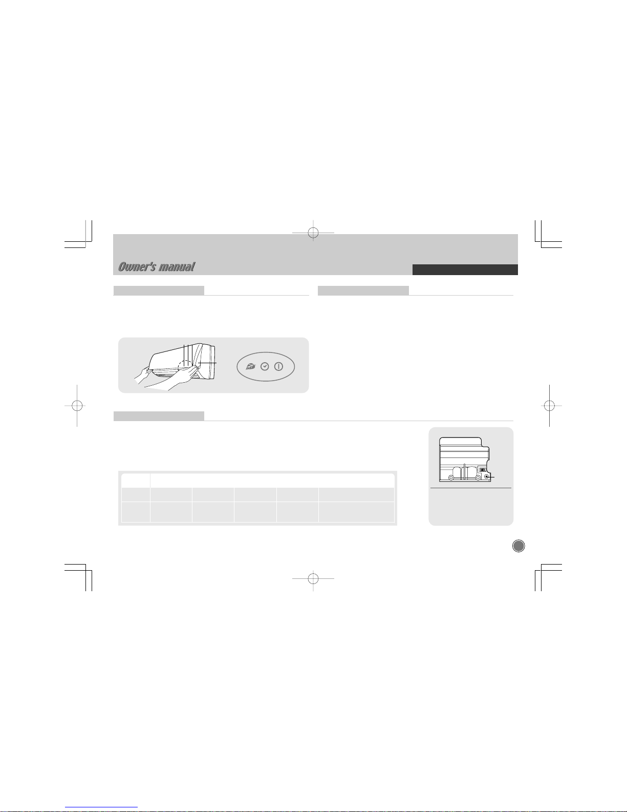
Emergency Operation
BEFORE OPERATION
햲 Blue light : illuminated during Ioniser activated.
햳 Orange light : illuminated during timer mode.
햴 Green light : illuminated during operation.
햵 EMER. button
When the remote control is lost, damaged or the battery is discharged, the EMER. button can be used to run the unit.
• Press the EMER. button once briefly at the off mode condition shorter than for 5 sec.
- According to the room temperature, the unit operates the Cool mode in cool only model and the Auto mode
in Heat pump model.
• If you want to stop the emergency operation, push the EMER. button again or operate the remote control.
• The setting conditions of emergency operation are as follows:
Indoor Unit Display
• EMER. button :
Can be used when the remote
control is lost or inoperative.
EMER.
button
Test Operation
This operation is used for checking after unit installation.
• Press the EMER. button continuously during 5~10sec. And then unit will be
operated as test mode.
• Press the EMER. button once more after checking to activate the remote
control. If there is any input signal ( remote control signal or EMER. button
press ) during test operation, the TEST mode will change to the input
signal mode.
• The setting conditions of the test operation are as follows:
- Operation mode : COOL - Fan speed : HIGH
- Timer mode : Disable - Discharge air direction : SWING
Cooling
only
Heat
Pump
Model Operation Preset mode Fan speed
Timer mode
Discharge air direction
temperature
COOL 24°C AUTO Disable Horizontal
AUTO 25°C AUTO Disable
Preset location according
to ‘Cool’ or ‘Heat’ mode
햵
햴
햳
햲
42KH5A54020_O 2004.6.17, 11:25 AMPage 5 Adobe PageMaker 6.5K/PPC

6
Setting Current Time and Reset
BEFORE OPERATION
Replacing Batteries
BEFORE OPERATIO
• Changing batteries should be done after turning off the unit.
NOTE
4
For this setting always use either button or .
With the remote control On or OFF,
press button for more than
5 seconds
Once the current time is set, press button
to confirm it.
5
The current hour figure flashes.Press either button or to
set the current hour. Press button
to move to minutes and
set them.
Press reset button with a sharp object if the remote control is not
operating properly or after replacing the batteries.
3
1
Remove the cover of the battery compartment at the back
of the remote control by sliding it out in the direction of the arrow.
Remove the used batteries and insert new batteries. The remote
control uses two batteries.(1.5V(L)R03x2)
2
6
7
42KH5A54020_O 2004.6.17, 11:25 AMPage 6 Adobe PageMaker 6.5K/PPC
7
When two units are used in the same room, you can match the address of
the remote control to that of the unit.
Turn off the unit and pull out the power plug. Remove the insert grille and
terminal block cover.
Assign the address selector of one indoor unit as B.
Refer the page 9.
BEFORE OPERATION
Matching Address between Indoor Unit and Remote Control
• This function must only be performed by qualified service personnel.
NOTE
Signal Receiving
Use the remote control where its signals can reach the receiver of the air
conditioner. (A distance of 5m is allowed)
• You can hear a beep from the unit which indicates that the signal is received.
5m maximum
Indoor Unit
Remote control
• The air conditioner will not operate if curtained, doors or other
materials block the signals from the remote control to the unit.
• If the infrared signal receiver on the unit is exposed to direct sunlight, the air
conditioner may not work properly. Draw the curtains to avoid direct sunlight.
CAUTION
• A mounting bracket for the remote control is supplied with the unit.
Install the mounting bracket on the wall where the remote signal can
be easily received from the remote.
8
BEFORE OPERATION
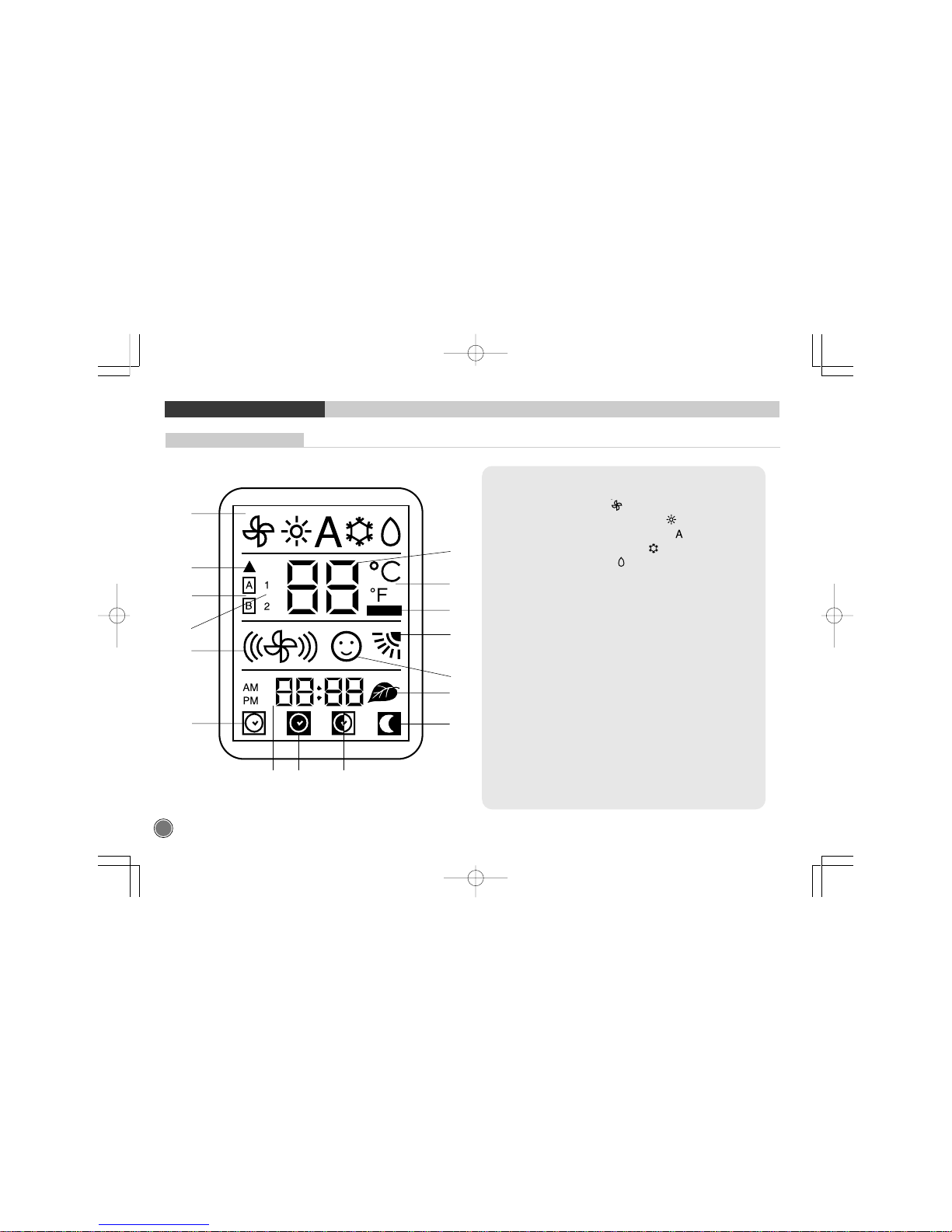
Remote Control Display
3
5
7
8
10
16
12
14 15 13
1
2
4
6
9
11
1. Operating mode (from left to right):
• Ventilation (fan only)
• Heating (heat pump models only)
• Automatic (heat pump models only)
• Cooling and dehumidification
• Dehumidification only
2. Signal transmission symbol
3. Temperature selected
4. Address selector
5. Temperature unit of measurement (°C or °F)
6. Unit configuration
7. Batteries exhausted indicator
8. Louvre positioning (Flap)
9. Fan speed
10. Personalisation active
11. ON timer selected
12. Night timer active
13. DAILY timer active (Everyday)
14. ON timer, OFF timer and current time
15. OFF timer selected
16. Ionizer active
42KH5A54020_O 2004.6.11, 3:6 PMPage 8 Adobe PageMaker 6.5K/PPC
9
1
BEFORE OPERATION
Remote Control Configuration
• Dew drop type remote is used for heat pump type air conditioner and cool
only type air conditioner.
Before user operates air conditioner, thus, cool only type and heat pump
type of remote configuration and other items must be selected as follows.
Press the and buttons of the infrared remote controller
and hold them pressed for more than 5 seconds.
The display will be cleared, the temperature segments will
display the first configuration item (CH = remote address) and
the time segments will display the default value of this
configuration item (A = control of both indoor units).
Press either the
or button to change the default value
(A) to the new value (b).
Press
button repeatedly until “tU” is displayed.
Press either the
or button to change the default value of
temperatures in Degrees Celsius (C) to the new value
Degrees Fahrenheit (
o
F).
Press
button repeatedly until “rc” is displayed.
Press either the or button to change the default value of
Heat pump in model type (HP) to new value cooling only
Export (CO1) or cooling only korean (CO2).
Press
button repeatedly until “CL” is displayed.
Press either the
or button to change the default value of
time format as AM/PM (12) to the new value of 24 hours time
format (24).
LOOK OUT! Whichever configuration value changed must
be confirmed pressing button each time.
Press
button to leave the configuration menu.
Note:
When 30 seconds have elapsed and no buttons have been
pressed, the remote controller will automatically exit the
configuration menu and the procedure has to be restarted.
9
2
3
4
5
6
7
8
10
11
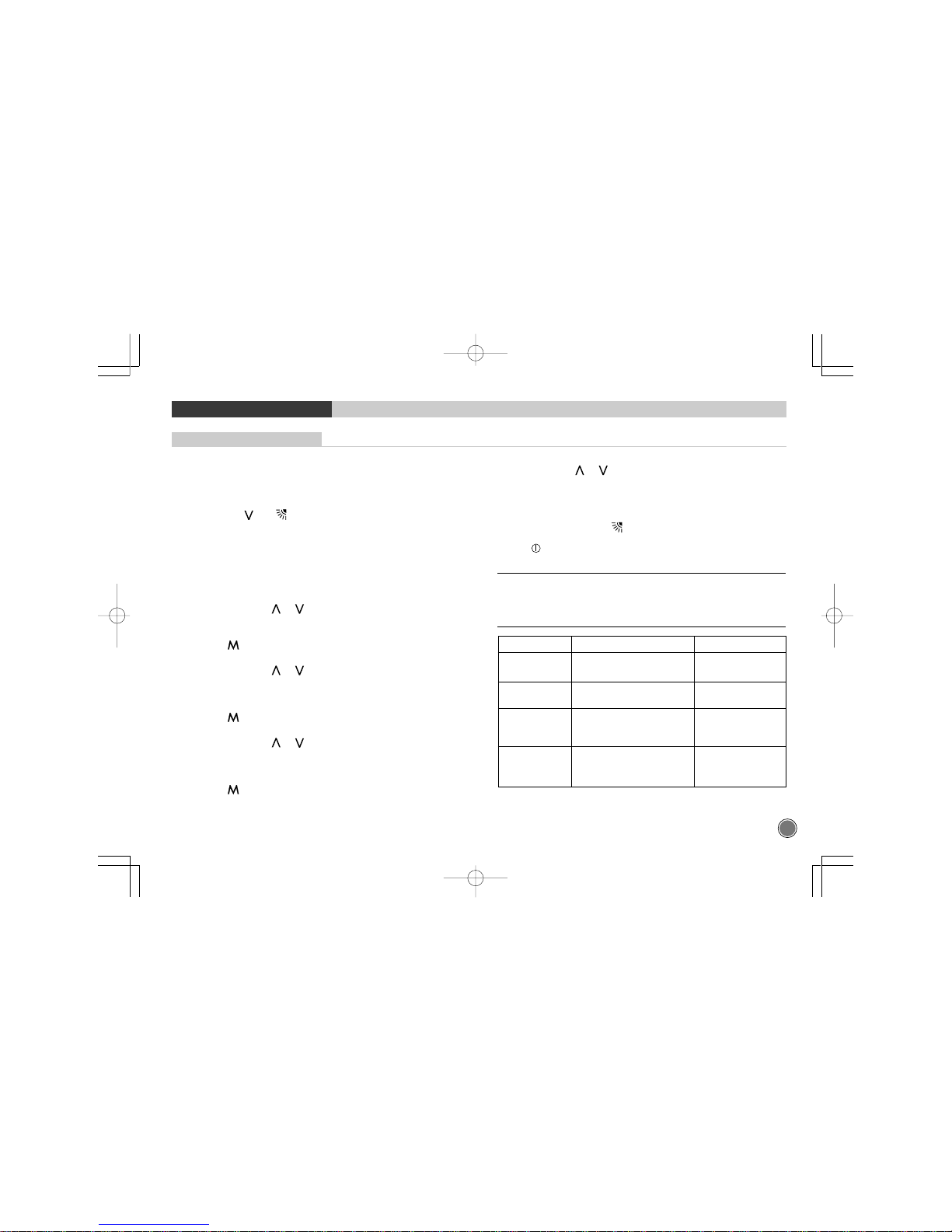
Confirguration item
Value Description
"CH" A : Channel A Remote ID selection
b : Channel B Defaults to A
"tU" C : Degrees C Temperature units
F : Degrees F Defaults to C
"rc" HP : Normal Operation Puts the Remote into
CO 1 : Cooling Only for Export Cooling Only Mode
CO 2 : Cooling Only for Korea Defaults to HP
"CL" 12 : 12 Hour Standard Time Format
(AM/PM) Defaults to 12
24 : 24 Hour Military
42KH5A54020_O 2004.6.11, 3:6 PMPage 9 Adobe PageMaker 6.5K/PPC