

Carrier NSB-10K-2-I-2, NSB-10K-2-I-8-BB2, NSB-10K-2-I-2-M304, NSB-10K-2-I-4, NSB-10K-2-I-8 Installation And Operation Manual
...Page 1
Immersion Temperat ure Sensors
Operation
Specifications subject to change without notice.
1 of 7
Catalog No. 11-808-632-01
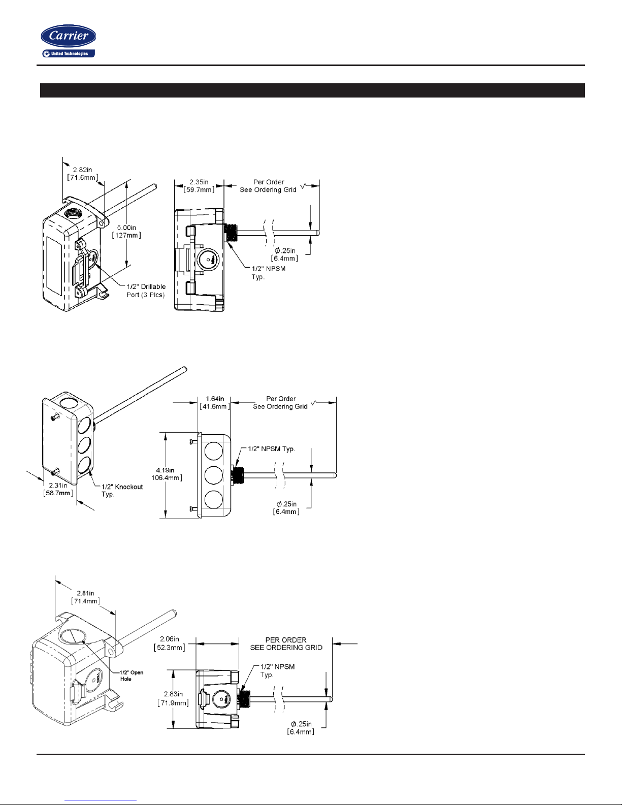
Figure 2: J-Box Immersion (Standard)
Part #
Figure 1:
Part #
NSB-10K-2-I-4-M304 (4” probe, 304 SS thermowell)
Figure
Part #
A Pierce
is available
#20907 – 2/20/19
Overview
The Immersion Temperature Sensor is made for thermowell mounting and temperature measurement in water pipes, water tanks or
cooling tower sump applications. The rigid probe is made of Stainless Steel and made in different lengths for a custom thermowell fit.
Enclosure mounting sty les come in plastic or metal for both NEMA 1 and NEMA 4 applications and are all plenum rated.
Installation and
BB2 Box Immersion
s NSB-10K-2-I-2-BB2 (2” probe, no thermowell)
NSB-10K-2-I-4-BB2 (4” probe, no thermow ell)
NSB-10K-2-I-8-BB2 (8” probe, no thermowell)
NSB-10K-2-I-2-M304 (2” probe, 304 SS thermowell)
s NSB-10K-2-I-2 (2” probe, no thermowell)
NSB-10K-2-I-4 (4” probe, no thermowell)
NSB-10K-2-I-8 (8” probe, no thermowell)
NSB-10K-2-I-2-M304 (2” probe, 304 SS thermowell)
NSB-10K-2-I-4-M304 (4” probe, 304 SS thermowell)
NSB-10K-2-I-8-M304 (8” probe, 304 SS thermowell)
3: BB4 Box Immersion
s NSB-10K-2-I-2-BB4 (2” probe, no thermowell)
NSB-10K-2-I-4-BB4 (4” probe, no thermowell)
NSB-10K-2-I-8-BB4 (8” probe, no thermowell)
able Knockout Plug (Part #NSB-PKP-100)
for the open port in the BB4.
Page 2

Immersion Temperat ure Sensors
Installation and Operation
Specifications subject to change without notice.
2 of 7
Catalog No. 11-808-632-01
Figure 4: Machined Bar Stock ThermoWell
Part #
Figure 5: Two-Part Welded Thermowell
Part #
#20907 – 2/20/19
Specifications
Sensor: Passive, 2 wire
Thermistor Thermal resistor (NTC)
Temp. Output Resistance Per Order1
Accuracy (std) ±0.36ºF, (±0.2ºC)
Stability 0.036ºF/Year, (<0.02ºC/Year)
Heat dissipation 2.7 mW/ºC
Temp. Drift <0.02ºC per year
Probe range -40º to 221ºF (-40º to 105ºC)
Sensitivity Approximate @ 32ºF (0ºC)
Thermistor Non-linier
Lead wire 22 AWG stranded
Insulation Etched Teflon, Plenum rated
Probe Rigid, 304 Stainless Steel,
0.25” OD
Probe Length 2” or 4”
Mounting ½” NPSM Plastic Threads
Enclosure Types
J-Box (-JB) With eight ½” knockouts
BB2 Box With three ½” NPSM & three ½” drill-outs
BB4 Box With three ½” drill-outs & one ½” open port
Enclosure Ratings
J-Box (-JB)
BB2 Box NEMA 4X,
IP66 BB4 Box IP10
Enclosure Materials
J-Box (-JB) Galvanized steel, UL94H-B
BB2 Box Polycarbonate, UL94V-0, UV rated
BB4 Box Polycarbonate & Nylon, UL94V-0
Ambient (Encl.) 0 to 100% RH, Non-condensing
BB2 & BB4 Boxes -40ºF to 185ºF, (-40º to 85ºC)
J-Box & No Box -40ºF to 212ºF, (-40º to 100ºC)
NEMA 1
(IP44 with Knockout Plug in the open port)
Thermowells
Thermowells are hollow tubes closed off on one end and threaded at the other end. They are permanently placed into pipes, tanks, or
sumps so that the probes on immersion temperature sensors can be inserted into the pipe. The temperature of the pipe’s contents is
transferred through the wall of the thermowell. The thermowell prevents the pipe’s contents from escaping and maintains the pressure
of pressurized pipes.
s ZSI-T-2-MB
ZSI-T-2-MSS
ZSI-T-4-MB
ZSI-T-4-MSS
ZSI-T-8-MSS
Agency RoHS, *CE
JIS C1604-1989
*Thermistors are CE compliant
s ZSI-T-2-WSS
ZSI-T-4-WSS
ZSI-T-8-WSS
Page 3
Immersion Temperat ure Sensors
Operation
Specifications subject to change without notice.
3 of 7
Catalog No. 11-808-632-01
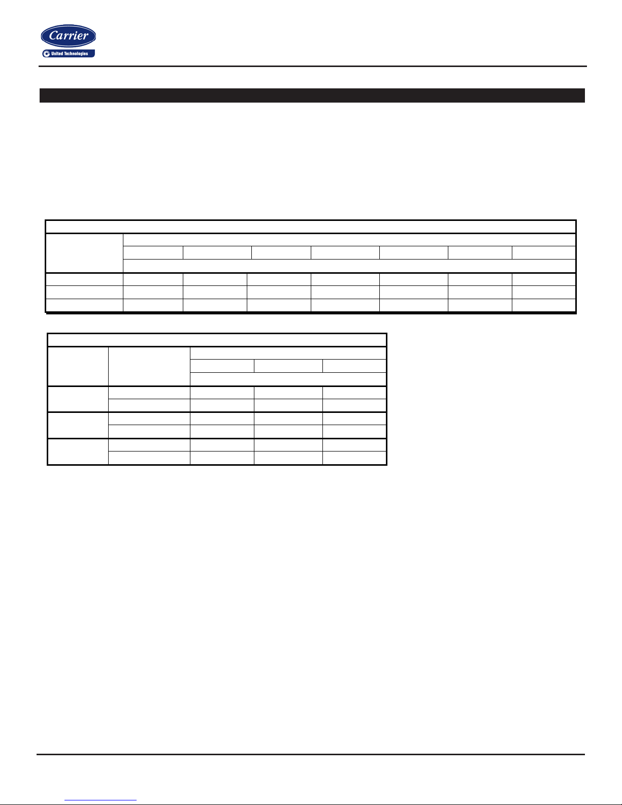
Table 2: Maximum Fluid Velocity versus Insertion Length
Insertion Length (inches)
1-2”
1-4”
1-8”
Maximum Fluid Velocity (Feet per second)
Air/Steam
207
75.5
27.3
Water
59.3
32.2
19.7
Air/Steam
169
61
20
Water
88
20
10
Air/Steam
300
109
39.5
Water
148
82.2
-
Table 1: Pressure Rating versus Temperature
Temperature in Degrees Fahrenheit
70ºF
200ºF
400ºF
600ºF
800ºF
1000ºF
1200ºF
Pressure Rating (Pounds per Square Inch)
Brass
5000
4200
1000 - - - -
Welded 304 SS
982
820
675
604
550
510
299
304 SS
7000
6200
5600
5400
5200
4500
1650
Installation and
#20907 – 2/20/19
Thermowells (continued…)
Choosing the correct Thermowell
As part of our ZS Sensor line, Carrier sells 2.5” and 4.5” machined thermowells made of Brass or 304 Stainless Steel (SS) and twopart welded thermowells made of 304 Stainless Steel. The two-part welded thermowells are not as strong as their machined
counterparts. Carrier recommends the use of welded thermowells be limited to small diameter systems in low vibration environments.
Carrier strongly encourages that single-piece machined thermow ells be used when pos si bl e. See the entries for Welded SS in the
following design tables. Additi onal ly , welded stainless steel thermowells should not be used in turbulent flow; ideally they should be
three to five pipe diameters from elbows or transitions.
Thermowell
Material
The values shown in Table 3 are based
on operating temperatures of 350ºF for
Thermowell
Material
Brass
Fluid Type
brass and 1000ºF for stainless steel.
Slightly higher velocities are possible at
lower temperatures.
Welded
304 SS
304 SS
Comparing the Wake Frequency and the Resonant Frequency
Table 2 and Table 3 were developed to insure that there will be no thermowell failures due to application stresses. Thermowell
failures, in most cases, are not due to the effects of pressure or temperature on the well. The calculations necessary to provide
adequate strength, under given conditions, are familiar enough to permit proper choice of wall thickness and material. The values
shown in Table 2 are conservative, and intended primarily as a guide.
Less familiar, and more dangerous, are the vibration effects to which thermowells are subjected. Fluid, flowing by the well, forms a
turbulent wake (called the Von Karman Trail) which has a definite frequency, based on the diameter of the thermowell and the velocity
of the fluid. It is important that the thermowell have sufficient stiffness so that the wake frequency will never equal the resonant (natural)
frequency of the thermowell itself.
If the resonant frequency of the thermowell coincided with the wake frequency, the thermowell would vibrate to destruction and break
off in the piping. Thermowells are also safe if the resonant frequency below the wake frequency or if the fluid velocity is constantly
fluctuating through the critical velocity point. Nevertheless, if the installation is not hampered by the use of a sufficiently stiff thermowell,
Carrier recommends the values given in Table 3 not be exceeded.
Page 4

Immersion Temperat ure Sensors
Installation and Operation
Specifications subject to change without notice.
4 of 7
Catalog No. 11-808-632-01
#20907 – 2/20/19
Thermowells (continued…)
Table 3: Pipe Insertion Recommendations using Carrier Thermowells
Thermowell Installation
To install a thermowell, a pipe fitter typically drills a
¾-inch hole into the pipe where the thermowell is
needed. A customer-provided fittin g, cal led a
Threadolet or Weldolet, is welded to the pipe over
the hole. The Threadolet has a ½” NPT thread in the
center. Thread sealant such as Teflon tape or pipe
dope is applied to the ½” NPT threads of the
thermowell. The thermowell is then inserted into the
Threadolet and tightened.
Figure 6 shows a 4” thermowell and 4” immersion
probe installed in a 12” pipe. In a properly
sensor
insulated pipe with liquid or steam, the temperature is
essentially the same across the entire cross-sect ion of the
pipe.Usually thermowells are sized to extend to the center
of the pipe; however, shorter thermowells will give proper
temperature readings if properly installed. The shor ter
thermowells are used in pipes with high flow velocities.
Since the wall thickness of the pipe commonly used
for HVAC plumbing is ½-inch, the thermowell sticks
four inches into the pipe. The four-inch distance is
from the inside surface of the pipe to the end of the
thermowell.
6.5” Overall
Probe Length
2” Thick
Pipe Insulation
1/2” Thick
Pipe Wall
(Schedule 80)
4” Thermowell
Insertion Length
Threadolet
Weld
Figure 6: Typical Immersion Probe Installed in a Thermowell
Page 5

Immersion Temperat ure Sensors
Operation
Specifications subject to change without notice.
5 of 7
Catalog No. 11-808-632-01
Length Per Order
*Sensor Slides
1.
Installation and
#20907 – 2/20/19
Thermowell Installation (continued…)
Pipes less than 3 inches in diameter
T- Mount
Figure 7 shows how a 2” tee and a ½” to 2” bushing
allows a 2” thermowelll to measure the temperature of the
contents of a 2” water pipe.
Be sure to use a thread sealant on the outside threads of
the thermowell.
Corner Mount
Figure 8 shows how a pipe tee can be used in an elbow
application. A 2” tee and a ½” to 2” bushing allows a 4”
thermowell to measure the temperature of the conte nts of
a 2” water pipe.
NOTE Temperatures in pipes as small as 1-1/4” may be
measured by this method. In small pipes, the diameter of
the thermowell may become a significant obstr u ctio n, so
be sure to check for proper flow rates after installation is
complete.
1/2 inch NPT
T-pipe fitting
Figure 7: Typical T-Mount
Reducer
Reducer
1/2 inch NPT
T-pipe fitting
Figure 8: Typical Corner Mount
Immersion Sensor Inst all at ion
Immersion probes come with a plastic fitting that
screws into the threads of the thermowell.
Pull the immersion probe away from the plastic fitting
until the probe is fullly extended. Insert the probe into
the thermowell until the plastic fi ttings come into contact
with the threads in the thermowell. Hand tighten the
immersion sensor snugly into the thermowell without
too much torque. The temperature probe slides back
into the enclosure as the sensor contacts the end of the
thermowell.
Make sure that the tip of the immersion sensor probe is
in good contact with the bottom of the thermowell by
pushing on the flaired end of the probe until the tip
bottoms out in the thermowell.
Pull Sensor to
Extend Fully
2.
Insert
3.
Hand Tighten
Figure 9: Immersion Sensor Before Insertion
* As the immersion sensor is hand-threaded into the thermowell, the flair end of the
probe will be pushed into the enclosure as the probe tip bottoms out in the
thermowell. The probe can slide up to 1.6”. The Junction Box enclosure is shown
above but the process is the same for the other enclosure styles.
Page 6

Immersion Temperat ure Sensors
Installation and Operation
Specifications subject to change without notice.
6 of 7
Catalog No. 11-808-632-01
Per order
*Sensor slides
1.
Pull sensor to
3.
Hand tighten
Per order
*Sensor slides
Per order
*Sensor slides
1. Pull sensor to
3. Hand tighten
4.
Pull sensor to
6.
Hand tighten
#20907 – 2/20/19
Immersion Sensor Inst all at ion (continued…)
Hand tighten into well
extend fully
2.
Insert
Figure 10: Typical Sensor Inserted Figure 11: BB4 Sensor Before Insertion
extend fully
2. Insert
extend fully
5.
Insert
Figure 12: BB2 Sensor Before Insertion Figure 13: Standard J-Box Before Insertion
*As the box is hand screwed, the probe will push into the box as the probe tip bottoms out in the well. The probe can slide up to 1.6 inches
Page 7

Specifications subject to change without notice.
7 of 7
Immersion Temperat ure Sensors
Installation and Operation
Catalog No. 11-808-632-01
Thermistor
To Controller
Analog Input (AI)
(No Polarity)
To Controller Analog
Figure 14: 2 Wire Lead Wire Termination for Thermistor
#20907 – 2/20/19
Wiring & Termination
Carrier recommends using twisted pair of at least 22AWG and sealant filled connectors for all wire connections. Larger gauge wire
may be required for long runs. All wiring must comply with the National Electric Code (NEC) and local codes. Do NOT run this device’s
wiring in the same conduit as high or low voltage AC power wiring. Tests show that inaccurate signal levels are possible when AC
power wiring is present in the same conduit as the sensor wires.
Sensor
Input (AI) (No
Polarity)
Diagnostics
Problems:
Controller reports higher or lower
than actual temperature.
Possible Solutions:
-
Confirm the input is set up correctly in the front end software
-
Check wiring for proper termination and continuity (shorted or open).
-
Disconnect wires and measur e sensor res ist anc e and ver ify the “Sen sor” outp ut is corre ct.
 Loading...