

Carrier Neos 100S, Integra 20X, Integra 35X, Integra 30S, Integra 40X Installation And Commissioning Manual
...Page 1

Installation & Commi ss ioning Manua l:
Truck Refrigeration
Neos 100S, 20X, 30S, 35X , 40X, 50X
INST ALLA TION AND
COMMISSIONING MANUAL
for
Neos 100S
62-11165 Rev D
62-11165 Rev D
®
Integra 20X, 30S, 35X, 40X,
Direct Drive Refrigeration Units
© 2017 Carrier Corporation • Printed in U. S. A. 0217
50X
1
Page 2

Installation & Commi ss ioning Manua l:
Neos 100S, 20X, 30S, 35X , 40X, 50X
Safety Precautions
Electrical Power
Beware of HIGH VOLTAGE supplied by the main power as
the unit may start automatically.
Before working on any unit, make sure that the main
Run/Stop switch is in STOP position and the negative
battery terminal is disconnected.
Fan Blades
All refrigeration units are equipped with Automatic Start/Stop
and may start at any time without warning. Beware all fan
®
62-11165 Rev D
blade, belts, and other moving parts.
Vehicle Battery
Vehicles are equipped with a lead-acid type battery. The
battery normally vents small amounts of flammable
hydrogen gas. Keep any flame, lighted object, or source of
spark away. A battery explosion can cause serious physical
harm and/or blindness
2
Page 3

Installation & Commi ss ioning Manua l:
Neos 100S, 20X, 30S, 35X , 40X, 50X
Safety Precautions
Electrical Conn ection
DISCONNECT the battery ground (-) on the vehicle battery.
Personal Protective Equipment
Always use personal protective equipment while doing
anything on this refrigeration unit.
Engine Coolant
All engines have a pressurized coolant system. Under
normal operating conditions, the coolant in the engine and
radiator is under high pressure and very hot. Do not remove
®
62-11165 Rev D
the cap from a hot radiator. If the cap has to be removed, do
so very slowly in order to release pressure without spray.
Refrigerants
The refrigerant contained in the refrigeration system of the
units can cause frostbite, severe burns, or blindness when in
direct contact with the skin or eyes.
3
Page 4

Installation & Commi ss ioning Manua l:
Neos 100S, 20X, 30S, 35X , 40X, 50X
Evaporator Clearances
B
A
®
62-11165 Rev D
Do not obstruct the evaporator fan
inlet(s) or outlet
For any movable bulkheads, there
must be a MINIMUM distance “A”
between the evaporator outlet and
any obstruction.
When mounting X Series
evaporators, it is recommended to
leave a MINIMUM distance “B” for
installation and service access.
MODEL
NEOS 100S, 20X
30S
35X,40X, 50X
“A” Minimum Distance
Inches (millimeters)
20.0” (500)
32.0” (800)
40.0” (1,000)
“B” Minimum Distance
Inches (millimeters)
6.0” (150)
Not Applicable
6.0” (150)
4
Page 5

Installation & Commi ss ioning Manua l:
Neos 100S, 20X, 30S, 35X , 40X, 50X
Condenser Installation – Roof T op A pplication
NEOS 100S
20X
8.86”
(225)
4 x Ø 0.56”
(4 x Ø 15)
21.65” (550)
3.54”
(90)
1.25” to 9.25”
(30 to 235)
Ø 3.50”
(Ø 90)
14.57” (370)
35X
®
62-11165 Rev D
30S
28.35” (720)
12.20”
(310)
4 x Ø 0.56”
(4 x Ø 15)
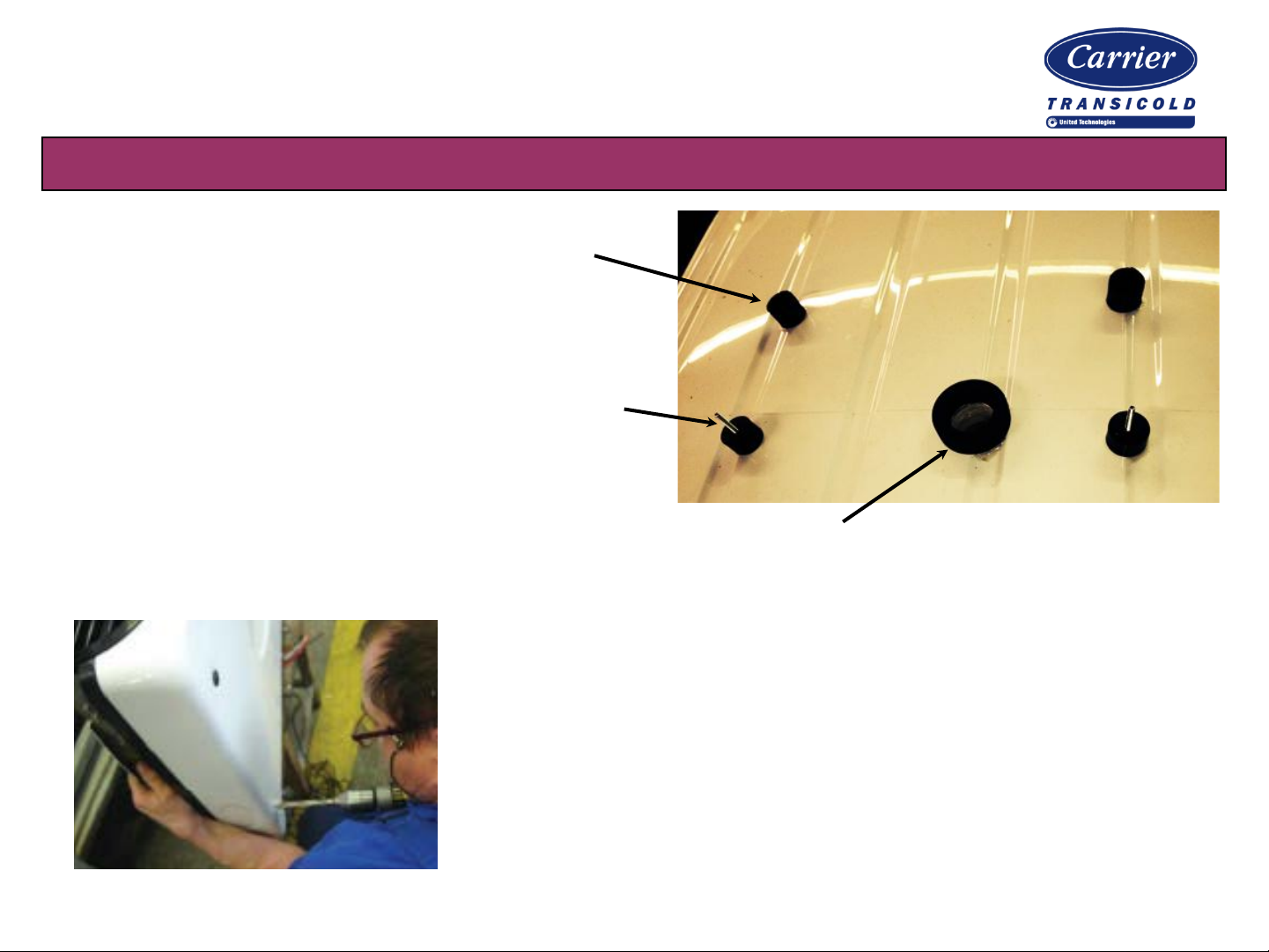
Note: For 30S, use the black ma rking on the
bottom cover of the unit as a template for drilling
the large refrigerant and electrical pass-thru hole.
Roof Top Applications
Mark and drill the four condenser
mounting holes, as well as the
larger refrigerant and electrical
pass-thru hole, as indicated
above (depending on unit model)
5
Page 6
Installation & Commi ss ioning Manua l:
Neos 100S, 20X, 30S, 35X , 40X, 50X
Condenser Installation – Roof T op A pplication
Install the four condenser mounting pads
by first applying waterproof silicone caulk
to the bottom cups in each pad.
Apply waterproof silicone caulk to each of the
four condenser mounting screws to prevent
water entry around the screw.
Apply waterproof silicone caulk to both sides of the center pad, which is used for
hoses and wiring, and install the center pad.
62-11165 Rev D
®
Remove the condenser cover. On the bottom cover of the
unit, drill the four 0.56” (15mm) mounting holes and the
larger electrical/hose hole as per the diagram on page 5.
Mount the condenser on the mounting pads in fasten in
place using the hardware supplied in the kit.
6
Page 7
Installation & Commi ss ioning Manua l:
Neos 100S, 20X, 30S, 35X , 40X, 50X
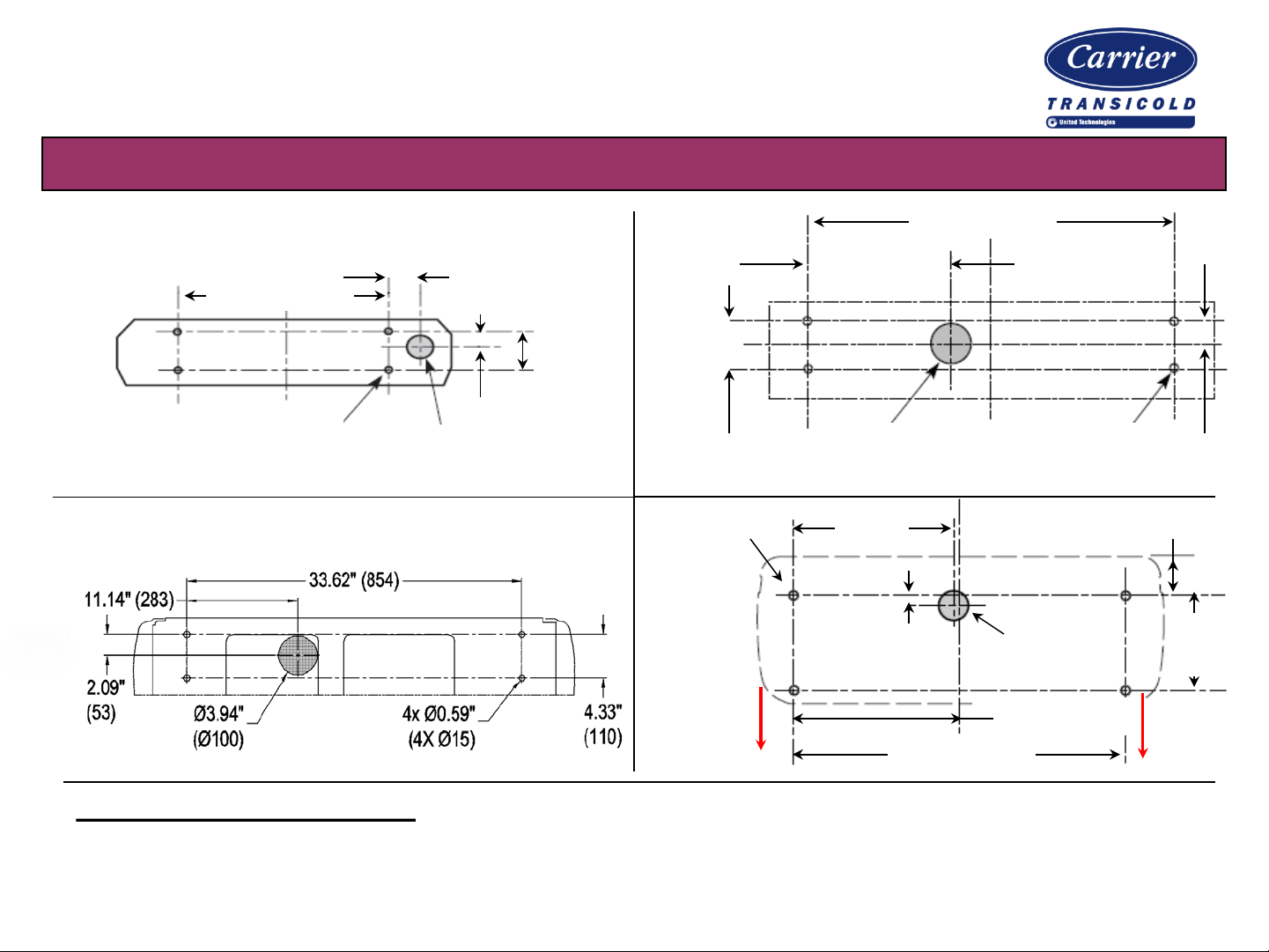
Condenser Installation – Front Mount Application
NEOS 100S, 20X
24.41” (620)
2.36”
(60)
5.12”
(130)
2.36” (60)
4 x Ø 0.56”
(4 x Ø 15)
35X
Ø 3.50”
(Ø 90)
4 x Ø 0.63”
(4 x Ø 16)
40X
50X
30S
4.33”
(110)
12.75”
(324)
Ø 4.0”
(Ø 100)
21.26”
(540)
1.18”
(30)
62-11165 Rev D
33.66” (855)
4 x Ø 0.56”
(4 x Ø 15)
Ø 4.0”
(Ø 100)
®
2.17”
(55)
5.31” (135)
12.6”
(320)
6” MIN to
cab roof
44.1” (1,120)
22.05” (560)
Front Mount Applications: Mark and drill the four condenser mounting holes, as well as the
larger refrigerant and electrical pass-thru hole, as indicated above (depending on unit model)
Bolt the condensing unit in place using the hardware supplied in the mounting kit.
7
Page 8

Installation & Commi ss ioning Manua l:
Neos 100S, 20X, 30S, 35X , 40X, 50X
Evaporator Mounting Preparation
20.86”
(530)
Neos
15.95”
(405)
30.71”
(780)
20X
100S
35X
40X
17.72”
(450)
17.72”
(450)
50X
30S
53.54” (1,360)
®
62-11165 Rev D
33.66”
(855)
18.5”
(470)
26.77” (680)
21.85”
(555)
40.55” (1,030)
Remove evaporator access panels. If the box has mounting studs, fasten the evaporator using supplied
hardware; otherwise, mark the mounting holes as indicated above (depending on unit model). Leave a
minimum of 6” (150mm) between the box wall and the rear of the evaporator.
58.27” (1,480)
29.13” (740)
8
Page 9
Installation & Commi ss ioning Manua l:
Neos 100S, 20X, 30S, 35X , 40X, 50X
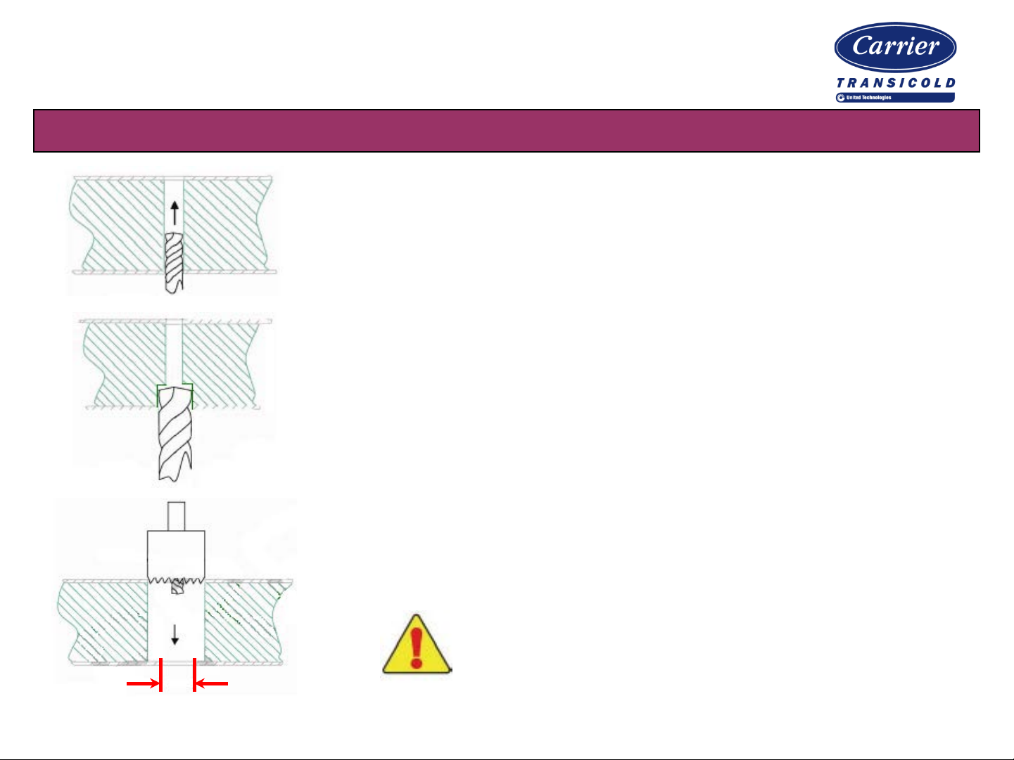
Evaporator Mounting Preparation – M ushroom Dri lling
From the inside of the box, drill 4 holes completely through
the roof of the vehicle using a 7/32” (5mm) drill bit.
From the inside of the box, step drill only through the inside
skin of the vehicle using a ½” (12.5mm) drill bit.
®
62-11165 Rev D
From the outside of the box, us e a 7/8” (22mm) hol e saw to
drill the outer roof of the box and the insulating foam.
0.50” (12.5)
Make certain NOT to drill all the way through
the roof. The ½” (12.5mm) hole in the inside
skin of the vehicle must remain intact.
9
Page 10

Installation & Commi ss ioning Manua l:
Neos 100S, 20X, 30S, 35X , 40X, 50X
Evaporator Mounting Preparation – M ushroom Instal lation
L
L
1
2 3
Measure the roof depth from the outside of the roof to the inside
of the inner box skin (distance “L”).
Measure mushrooms from the bottom of the head
to end of the mushroom. Mark and cut them to the
same length “L”. Apply waterproof silicone caulk to
the underside of the mushroom head and tap into
the vehicle roof to slightly crush the caulk. Bolt the
evaporator in place using the hardware supplied.
The correct bolting arrangement is show with the mushrooms
®
62-11165 Rev D
4
5 6 7
8
and evaporator in place. Note that the evaporator should not
press directly against the mushrooms due to the step drilling.
1) Mushroom (34-01262-00)
2) Silicone caulk
3) V ehicle roof
4) Box insulation
5) Inner box skin
6) Evaporator housing
7) Washer
8) Mounting screw
10
Page 11

Installation & Commi ss ioning Manua l:
Neos 100S, 20X, 30S, 35X , 40X, 50X
Evaporator Mounting – Drain Line Installation
Install the evaporator drain lines.
A MINIMUM drop of 4.0” (100mm) is
recommended between the drain pan outlet
and where the drain lines exit the vehicle.
Note the difference in drain line recommendations
4.0” (100)
For perishable applications, connect the water drain hoses
together and route outside the vehicle. Note the diagram
showing recommended ways of routing the lines.
for perishable versus frozen applications
®
62-11165 Rev D
For frozen applications, do NOT tee drain lines together. It is
important for each line to directly exit the vehicle in as short a
distance as possible to prevent condensate from freezing.
Make certain there are no low spots that can
trap w ater in any of the drain line routings .
Secure drain lines in place using ty-wraps or clamps.
11
Page 12

Installation & Commi ss ioning Manua l:
Neos 100S, 20X, 30S, 35X , 40X, 50X
Refrigerant Hose Installation – Handling Recommendations
For proper functioning of the refrigeration unit,
the hoses must be kept clea n and dry
It is recommended to leave the caps installed on
the ends of the hoses while routing them to
prevent internal dama ge or moi stur e entry.
Make sure to use the clamps provided in the installation kit to
secure the hoses and keep them from vibrating or rubbing.
When securing hoses, note the hoses will slightly change length
under pressure. When securing and clamping the hoses, make
sure to account for the slight variations in length that will occur.
®
62-11165 Rev D
Minimum Bend Radius
#6 hose (3/8”) 3.5” (90mm)
#8 hose (1/2”) 4.0” (100mm)
#10 hose (5/8”) 4.5” (115mm)
#12 hose (3/4”) 5.25” (135mm)
Use the rubber grommets provided in the installation kit when
passing through holes and bulkheads to prevent the hoses and
electrical wires from rubbing on any sharp edges.
As shown in the diagram, do not twist, curve or
route the hoses in any manner which will stress
the hose. Use as large a bend radius as possible.
Use elbows and fitting as necessary to ease
installation and increase hose life.
12
Page 13

Installation & Commi ss ioning Manua l:
Neos 100S, 20X, 30S, 35X , 40X, 50X
Refrigerant Hose Installation – Installation Preparation
Always use the required tools as follows:
Hose Cutting / Crimping Kit: 07-60117-00
Fitting Insertion Tool: 07-60177-00
Cut the hose to the required length using
the Carrier hose cutting tool.
®
62-11165 Rev D
Lubricate the inside of the hose end with
POE oil.
Widen the internal hose clearance using
the expanding tool before sliding the
double zinc clamp over the hose.
13
Page 14

Installation & Commi ss ioning Manua l:
Neos 100S, 20X, 30S, 35X , 40X, 50X
Refrigerant Hose Installation – Installation Preparation
Lubricate the fitting and O-ring with POE oil.
Insert the connector into the hose.
To avoid damaging to the O-ring, do NOT twist
the fitting during or after inser tion i nto the hose
®
62-11165 Rev D
Crimp the double zinc clamp using the required crimping tool.
You will need to prepare up to 5 refrigerant lines, as indicated:
• Oil return line (all units EXCEPT 20X)
• Discharge line
• Liquid line
• Hot gas line
• Suction line
14
Page 15

Installation & Commi ss ioning Manua l:
Neos 100S, 20X, 30S, 35X , 40X, 50X
Refrigerant Connection Lines – Neos 100S / 20X ONLY
Liquid
90° ORS 3/8”
Hot Gas
90° ORS 3/8”
Road Suction
O-Ring pilot 5/8”
Road Suction
90° ORS 5/8”
Low Pressure
Service Valve
5/8”
High Pressure
Service Valve
1/2”
®
62-11165 Rev D
Evaporator
Liquid Line
90° ORS 3/8”
Hot Gas
90° ORS 3/8”
Neos 100S /
20X
ONLY
Road Compressor
Road Discharge
O-Ring pilot 1/2”
Road Discharge
90° ORS 1/2”
Condenser
15
Page 16

Installation & Commi ss ioning Manua l:
Neos 100S, 20X, 30S, 35X , 40X, 50X
Refrigerant Connection Lines – 30S ONLY
Standby
Hot Gas
90° ORS 3/8”
Road Suction
O-Ring pilot 5/8” -> ¾”
Road Suction
90° ORS ¾”
Low Pressure
Service Valve
3/4”
High Pressure
Service Valve
Suction
90° ORS 5/8”
½”
Liquid
90° ORS 3/8”
Standby Units
Hot Gas
90° ORS 3/8”
62-11165 Rev D
Evaporator
ONLY
Liquid Line
®
90° ORS 3/8”
30S ONLY
Road
Compressor
Oil Return
90° ORS ¼” -> 3/8”
Road Discharge
O-Ring pilot ½”
Road Discharge
90° ORS ½”
Condenser
Standby Suction
90° ORS 5/8”
16
Page 17

Installation & Commi ss ioning Manua l:
Neos 100S, 20X, 30S, 35X , 40X, 50X
Refrigerant Connection Lines – 35X, 40X, 50X ONLY
Standby
Hot Gas
90° ORS 3/8”
Road Suction
O-Ring pilot 5/8” -> ¾”
Road Suction
90° ORS ¾”
Low Pressure
Service Valve
3/4”
High Pressure
Suction
90° ORS 5/8”
Service Valve
5/8”
90° ORS 3/8”
90° ORS 3/8”
Liquid
Hot Gas
Evaporator
Standby Units
ONLY
®
62-11165 Rev D
Liquid Line
90° ORS 3/8”
35X, 40X, 50X
ONLY
Road
Compressor
Oil Return
90° ORS ¼” -> 3/8”
Road Discharge
O-Ring pilot ½”
Road Discharge
90° ORS 5/8”
Condenser
Standby Suction
90° ORS 5/8”
17
Page 18

Installation & Commi ss ioning Manua l:
Neos 100S, 20X, 30S, 35X , 40X, 50X
Electrical Connections
®
62-11165 Rev D
If required, route the Return Air Sensor
(RAS) and mount to the evaporator fan inlet.
Make all required electrical connections.
Note that most are connectors that are “plug
and play”. The required electrical
connections are listed as follows:
Evaporator Connections:
• Evaporator fan motor(s)
• Return Air Sensor (RAS)
• BPV (quench valve)
• Low Pressure switch
Engine Compartment:
• CLHR (road clutch)
• BBT (quench thermostat)
18
Page 19

Installation & Commi ss ioning Manua l:
Neos 100S, 20X, 30S, 35X , 40X, 50X
Cab Command Installation
Route the cab command harness to the interior of the vehicle
Protect the harness from all sharp sheet metal
Make sure the harness is not in c ontact with anything hot
Make certain the harness is secured from vibration
Mount the cab command in a accessible location
where it may not be damaged; for example, where
the rear view mirror would otherwise be mounted.
®
62-11165 Rev D
Be careful not to damage any of the vehicle hoses or wires.
If it is mounted i n the das hboard, k eep as far as possibl e from heating ducts.
Maximum exposure temperature: 158°F (70°C).
Do not mount it where it can be exposed to constant, dire ct sunl ight
19
Page 20

Installation & Commi ss ioning Manua l:
Neos 100S, 20X, 30S, 35X , 40X, 50X
Compressor Mounting
Install the road compressor on the vehicle following the bracket manufacturer’s
installation instructions.
Connect the high pressure line (HP) and the larger
HP
suction line (LP).
Install the injection thermostat (BPT) on the compressor
BPT
high pressure line using the supplied clamp.
Make sure the injection thermostat is making
LP
good contact with the high pressure line.
62-11165 Rev D
®
Make electrical connections for the injection thermostat and
the compressor clutch. Place wires in protective split loop.
After connecting the injection thermostat terminals,
insulate the injection thermostat body with the
insulating material supplied.
20
Page 21

Installation & Commi ss ioning Manua l:
Neos 100S, 20X, 30S, 35X , 40X, 50X
Battery and Ignition Harness Connections
Route the neiman cable to the vehicle fuse box. Connect the wire
to the 1 A mp fuse holder supplied in the mounting kit.
Connect to a +12Volt DC switched circuit (refer to the specific
vehicle manufacturer’s recommendations).
Cut the battery harness to the required length. Strip back both the
positive (+) and negative (-) harness wires, crimp the electrical
terminals on, and connect to the corresponding terminals on the
fuse holder.
It is recommended to also use soft solder on the
terminal connections.
®
62-11165 Rev D
Mount road fuse holder as close as possible to the vehicle battery.
Put electrical grease on fuse holder connections, install the road
fuse supplied in the installation kit, and put protective cap on.
Connect the unit ground (-) to the vehi cle chassis.
Re-connect the vehicle battery ground (-) to the battery.
21
Page 22

Installation & Commi ss ioning Manua l:
Neos 100S, 20X, 30S, 35X , 40X, 50X
Evacuation, Leak Checking, and Refrigerant Charging
The presence of moisture in a refrigeration system can have many undesirable
effects, such as sludge formation, “freezing up” of metering devices, and metal
corrosion caused by acid formation. Make every effort to keep the system dry.
After performing a pressure leak test, evacuate and dehydrate the system.
Essential tools to properly evacuate and
dehydrate a system include a good
vacuum pump (5 cfm=8m
P/N 07-00176-01) and a good vacuum
gauge indicator (P/N 07-00414-00).
NOTE: a compound gauge is NOT recommended
3
H displacement,
®
62-11165 Rev D
Keep the ambient temperature above 60°F (16°C) to speed evaporation of moisture. If the
ambient is lower than 60°F (16°C), ice may form before moisture removal is complete. If
necessary, heat lamps or alternate sources m ay be used to raise system temperature.
The unit is shipped with a dry nitrogen holding charge. Remove the nitrogen, and then
evacuate and dehydrate the system by connecting three hoses (do not use standard
service hoses) to the vacuum pump and refrigeration unit. Connect an evacuation manifold
with evacuation hoses only to the vacuum gauges and refrigerant recovery system.
22
Page 23

Installation & Commi ss ioning Manua l:
Neos 100S, 20X, 30S, 35X , 40X, 50X
Evacuation, Leak Checking, and Refrigerant Charging
Check the evacuation system for leaks: Without being connected to the inline service ports,
open the vacuum pump and manifold gauge valves and start the pump and draw a deep
vacuum. Shut off the pump and check to see that the vacuum holds. Repair if necessary.
Connect the manifold gauge set hoses to the service ports. Open the
vacuum pump and manifold gauge valves (if they are not already open)
and start the vacuum pump. Evacuate unit until the vacuum gauge
indicates 2,000 microns. Close the vacuum gauge and vacuum pump
valves. Wait a few minutes to be sure the vacuum holds.
62-11165 Rev D
®
Break the vacuum with clean, dry nitrogen. Raise system
pressure to approximately 2 psig
Repeat the steps outlined above one more time.
23
Page 24

Installation & Commi ss ioning Manua l:
Neos 100S, 20X, 30S, 35X , 40X, 50X
Evacuation, Leak Checking, and Refrigerant Charging (Final Step)
Evacuate the unit to 500 microns. Close off the vacuum pump valve and stop the pump. Wai t
five minutes to see if the vacuum holds. This checks for residual moisture and/or leaks.
With a vacuum still in the unit, the refrigerant charge may be drawn into the system from a
refrigerant container on weight scales. The correct amount of refrigerant may be added by
monitoring the scales.
Make sure to use the correct
refrigerant for each refrigeration unit.
When the correct charge has been added, close the unit
manifold valves and disconnect the manifold gauges.
MODEL Refrigerant
Type
Refrigerant Charge
Pounds Kilograms
62-11165 Rev D
®
Neos 100S R134a 2.2 lb. 1 kg
20X R404a 3.10 lb. 1.4 kg
30S R134a 4.00 lb. 1.8 kg
35X R404a 3.30 lb. 1.5 kg
40X R404a 6.60 lb. 3.0 kg
50X R404a 7.05 lb. 3.2 kg
24
Page 25

Installation & Commi ss ioning Manua l:
Neos 100S, 20X, 30S, 35X , 40X, 50X
Evacuation Process
5000
4500
4000
3500
3000
2500
2000
(Inches of Hg)
®
62-11165 Rev D
1st Step
2nd Step
1500
Final Step
1000
Vacuum Indicated By The Meter
500
0
Dry & Tight Circuit
0 1 2 3 4 5 6 min
25
Page 26

Installation & Commi ss ioning Manua l:
Neos 100S, 20X, 30S, 35X , 40X, 50X
Evaporator CPR Adjustment
The Compressor Regulation Valve (CPR) is designed to regulate the flow of refrigerant
returning to the compressor from the evaporator and ensures the correct capac ity of the unit.
The CPR also reduces compressor start-up and operation load. It is critical it is set correctly.
CPR adjustment MUST be done under the foll owing conditions:
• Road operation at 2,400 compressor RPM
• Heat or Defrost mode
Connect manifold gauges to the CPR fitting port.
Start the unit in Heating or Defrost mode. Check that
the road compressor speed is 2,400 RPM
Remove the cap on the CPR valve.
62-11165 Rev D
®
Adjust the CPR with an 8mm Allen (hex head) wrench
to get correct gauge pressure (see next page).
• To raise the suction pressure, turn the set screw
clockwise
• To low e r the suction pr ess ure, turn the s et
screw counter-clockwise.
26
Page 27

Installation & Commi ss ioning Manua l:
Neos 100S, 20X, 30S, 35X , 40X, 50X
Evaporator CPR Adjustment
* The CPR adjustment must be INCREASED by approximately +0.5 psi for
every additional foot (+ 0.1 bar per meter) that the evaporator is locate d
(distance D minus 6”) fr om the front wall of the vehicle.
MODEL CPR Setting at CPR Port
PSI BAR
Neos 100S 10.3 psi .7 bar
20X 27.5 psi 1.9 bar
30S* 18.9 psi 1.3 bar
35X 30.5 psi 2.1 bar
40X 33.4 psi 2.3 bar
50X 37.7 psi 2.6 bar
®
62-11165 Rev D
D
*Only the 115V standby versio n o f the 30S has a CPR .
No other 30S versions require adjustment.
When the setting has been adjusted, tighten the
jam nut securely against the setting screw to
prevent any vibration of the set screw (and to
prevent disruption of the CPR setting).
Replace the CPR cap and remove gauges.
27
Page 28

Installation & Commi ss ioning Manua l:
Neos 100S, 20X, 30S, 35X , 40X, 50X
Evaporator TXV Setting
®
62-11165 Rev D
The Thermo Expansion Valve (TXV) is
designed to precisely meter the flow of
liquid refrigerant into the evaporator
and control the refrigerant gas leaving
the evaporator.
The evaporator outlet pressure (P2)
must be converted to saturation
temperature (T3) using a P/T chart.
The superheat is the difference
between the temperature at the bulb
location (T1) and the evaporator outlet
T1
P2
saturation temperature (T3).
Connect a gauge to the evaporator
outlet fitting. Put a thermocouple at
the expansion valve bulb location and
insulate it. Run the unit in Cool mode.
28
Page 29

Installation & Commi ss ioning Manua l:
Neos 100S, 20X, 30S, 35X , 40X, 50X
Evaporator TXV Setting
To INCREASE superheat, turn clockwise
To DECREASE superheat, turn counter-clockwise
®
62-11165 Rev D
Repeat process a
minimum of 3 times
SUPERHEAT = T1 – T3
Superheat at
MODEL
ALL 14.5°F
To complete the installation, re-install any evaporator panels.
32°F (0°C) Box
8°C
Superheat at
0°F (-20°C) Box
7°F
4°C
29
Page 30

Installation & Commi ss ioning Manua l:
Neos 100S, 20X, 30S, 35X , 40X, 50X
North America
Carrier Transicold
700 Olympic Drive
Athens, GA 30601 USA
Tel: 1-706 -357 -7223
Fax: 1-706 -355 -5435
Central America
and Mexico
Ejercito Nacional 253 - A Piso 5
Colonia Anahuac
11320 Mexico, D.F.
Tel: 55315010
Fax: 55315010 ext. 1005
®
62-11165 Rev D
Carrier Transicold Division,
Carrier Corporation
P.O. Box 4805
Syracuse, N.Y. 13221 U.S.A.
www.carrier.transicold.com
A member of the United Technologies Corporation family. Stock symbol UTX
30
 Loading...