

Page 1
.
.................. 'Й
‘Ш 1
Electric Heating: 182,500 to 808,000 Btuh
Electric Cooling: 220,000 to 753,000 Btuh
Sirag
là
pi^eE)
©
'"((Doieg umts
1.
in®
1Ш“,
® I 1
p
Air Distribiitioin S|/steni
Jr MociM-rac
Electric Cooling: 220,000 to 744,000 Btuh
Versatile
rooftop units —
for constant or
Moduline® for
VAV system
variable air volume
applications in the
20- to 60-ton range
NOW — with energysaving features for
years of outstanding
performance
• SOLID-STATE CONTROL
LOGIC
• INTEGRATED ECONOMIZER/MECHANICAL
COOLING
• LOW-LEAKAGE
DAMPERS
• INTERTWINED COILS
• TWO-SPEED INDOOR "
FAN OPTION
' Carrier Corporation 1982
Form 50DF-2P
Page 2

£
FEATURES AND BENEFITS
OPTIONS AND ACCESSORIES
PHYSICAL DATA
BASE UNIT DIMENSIONS
ACCESSORY DIMENSIONS
SELECTION PROCEDURE
PERFORMANCE DATA
Cooling Capacities
Heating Capacities
Optional Equipment Resistances
Indoor Air Fan Pulley Data
Fan Performance
ELECTRICAL DATA
CONTROLS
Operating Sequence
Electrical Protection
TYPICAL WIRING SCHEMATIC
APPLICATION DATA
TYPICAL PIPING AND WIRING
GUIDE SPECIFICATIONS
50DF
3
4,5
6
7
8
9
9,10
10
10
11
12
13-15
16
17
18
19
16
20,21
50DF Modu"Pac@
22-24
24
25
26
27
28
29,30
32
32
32
31
33
32
33
34
—
35
36
VL
Page 3
50DF
High quality features assure easy installation
— plus performance and energy savings
Solid-state components for precise
system control — Units contain a
solid-state control system that pro
vides maximum operating economy.
The “brain” of the system is a logic
panel that offers 2-stage heating and
cooling modes based on space re
quirements. Panel also is the logic net
work that coordinates operation of the
economizer, energy management and
two-speed indoor fan options.
Solid-state components require no
calibration, are easily replaced and
have long operating life.
Practical curb design for low in
stallation costs — The curb supports
unit on the roof. Eliminates special steel
support frames and assures a low roof
silhouette. Weatherproof enclosure
eliminates need for a rooftop adapter or
roof openings that could be sources
of troublesome leaks. All utilities enter
unit within the curb; saves time and
reduces installation costs. A wood nailstrip is also included.
Adaptable duct connections — The
Carrier design provides large duct
openings that permit low airflow veloci
ties and even air distribution. Bottom
supply and return ductwork is easily
installed. Concentric ductwork with
diffusers also may be connected to the
20-, 25-, and 30-ton units.. .with no
internal modifications.
For convenience, alternate side supply
and return openings are provided for
horizontal duct applications. Simply
relocate side supply and return panels,
place them in the bottom openings,
relocate one interior panel and the unit
is quickly converted for side duct con
nection. An accessory conversion kit
is required for units with economizer.
Factory-installed filter rack includes
2-in. filters.
115-volt convenience outlet — An
on-the-job power source for service
light or hand tools.
Pre-installed tracks for hydronic coil
application. Factory installed on units
without electric heat option.
Weather Armor cabinet stands up to
the weather. Cabinet design exceeds
UL and Carrier rain test requirements.
Units keep attractive appearance for
years — even in salt air or heavy in
dustrial environment.
Time Guard® circuit — Compressor
will not short cycle on a safety device or
power interruption. Starts outdoor air
fans 15 seconds before compressor to
minimize solar heat buildup and reduce
start-up load.
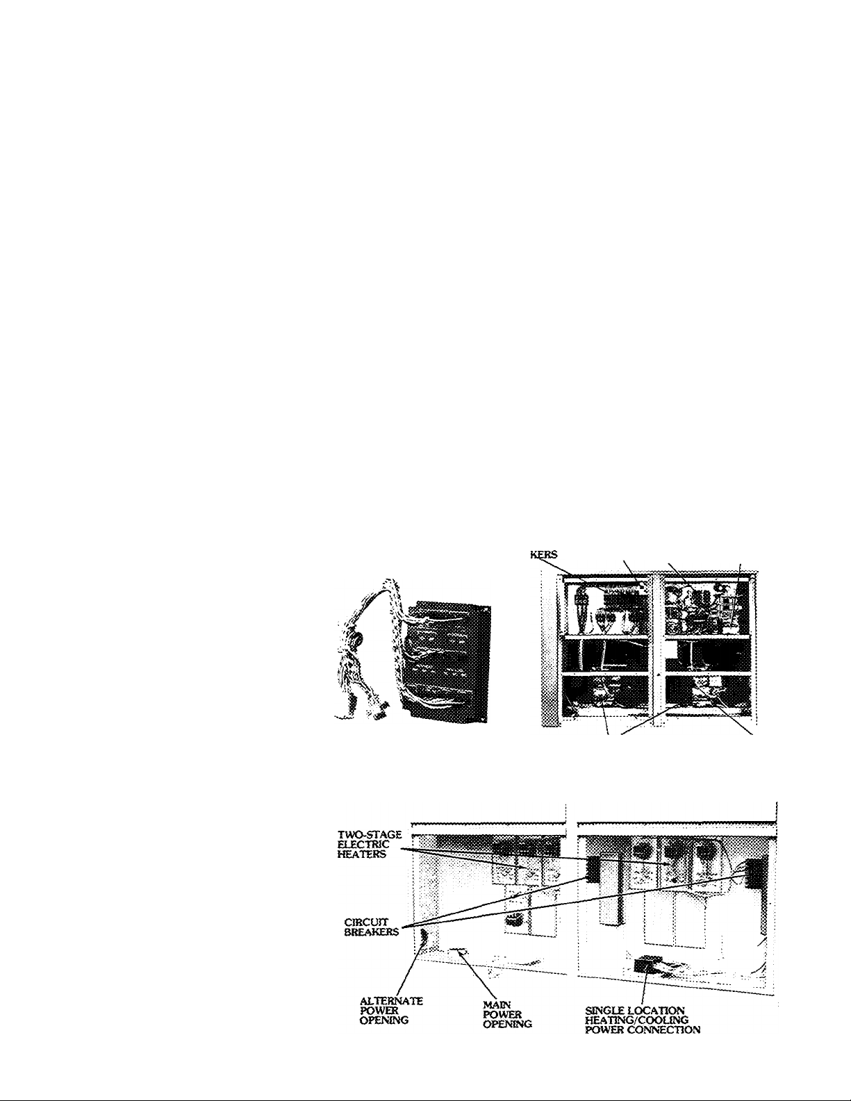
Single-location power connections
— Unit is factory wired with all heating
and cooling power circuits internally
routed to a terminal block in one com
partment. Some units, with higher heat/
cool ratios, have 2 terminal blocks. No
need to route expensive wiring to
separate heating and cooling power
locations. Saves time, money and labor.
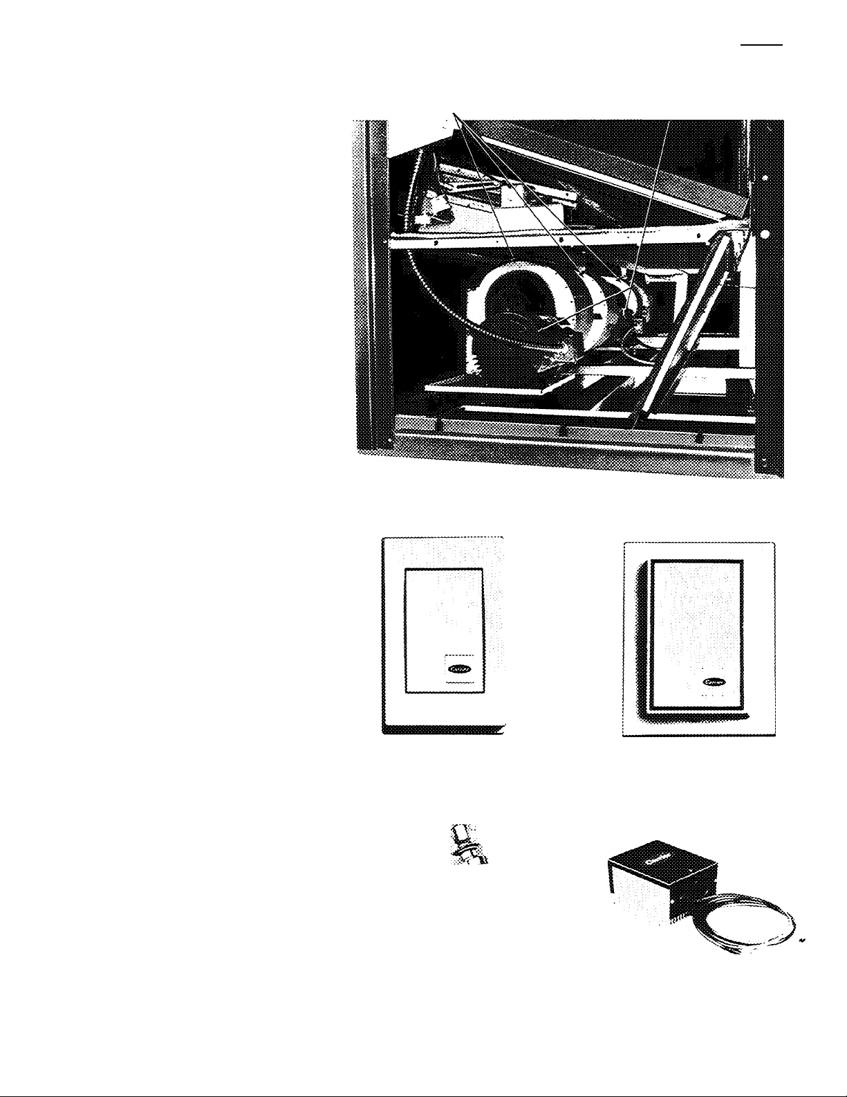
Fixed-speed evaporator fan drive —
less vibration than variable-speed drive.
Extends belt life and minimizes drive
noise.
Manual damper, on standard units,
can be preset to admit as much as 25%
outdoor air for year-round ventilation.
Cfficurr
8REA:
LOGIC PANEL
Built-in convenience — Quick-release
access panels, slide-out filters and plug
in relays simplify routine inspection
and maintenance.
Carrier-built intertwined refrigerant
coils have staggered copper tubes with
mechanically bonded fins to ensure
optimum heat transfer. Intertwined
design provides cooling of the full air
stream with minimum compression.
Direct-drive condenser fans are
factory lubricated. Vertical discharge
moves air quietly and efficiently.
Carrier compressors have factoryinstalled service valves, crankcase
heaters, reversible oil pumps, mufflers,
overloads in the control box and
internal motor protection. Liquid line
sight glasses and filter driers are also
included.
Low-ambient temperature capa
bility permits all units to operate at out
door temperatures as low as 35 F.
CON\gv(IENCE logic LOW VOLTAGE
OUTLET , PANEL TERNHNAL BLOCK
CARRIER SERVICEABLE
HERMETIC COMPRESSORS
«LEAD
COMPRESSOR
(Uses Suction
Pressure)
Page 4

Factory-installed options and
field-installed
accessories offer flexibility to
application
Modulating outdoor air control
package (economizer) — Even when
outdoor air temperatures are low, many
installations still require cooling. The
economizer uses the cool outside air to
provide this cooling. Saves energy,
reduces compressor wear and tear and
lowers operating costs.
The economizer contains these
energy saving features:
• Electronic control logic balances
the conditioned space demand against
the cooling system output. Ensures that
the economizer modulates to correct
position or closes to minimum position
to maintain a stable temperature in the
conditioned space. Never too much or
too little cooling.
The control logic also integrates
economizer cooling with mechanical
cooling. If outdoor enthalpy permits,
economizer acts as first stage of cooling.
If conditioned space requires more
cooling, economizer works in conjunc
tion with mechanical cooling to maintain
required indoor temperature.
The integrated system supplies only
the amount of mechanical cooling
necessary.
• Low-leakage dampers limit infiltra
tion. Rated by the manufacturer at 3%
with 3-in. wg pressure differential.
• Spring return damper motor auto
matically closes the outdoor air dampers
in the event of a power failure. (Option
or Accessory)
Two-speed indoor fan option —
Substantial energy cost savings can be
obtained because fans automatically
operate at low speed during most cool
ing operating hours. High speed is used
only if and when necessary to maintain
comfort conditions.
A 4-stage electronic logic panel
selects the most efficient fan speed and
compressor stage to satisfy room de
mand. Economizer performance is
optimized by utilizing low-speed opera
tion except when space conditions
require the additional capacity of high
speed “free cooling”.
The two-speed option is available in
either standard or alternate motor
sizes. All control and power wiring are
factory installed; thus, costly field wiring
and adjustments are not necessary.
The two-speed fan motors are 2
winding (4 pole/6 pole) with rpm’s of
1760/1170.
Power exhaust — Coupled with the
economizer, up to 75% of the return air
can be exhausted. Also, eliminates
over-pressurization of the building.
Designed for use with bottom duct
connection arrangements. Used only
with economizer. (Option or Accessory)
Electric heaters — Three factory-
installed and one field-installed heating
capacity are available. Factory wired for
2-stage heat. Outdoor air thermostats
can be added to provide additional
stages as required. Branch circuit pro
tection is built in on each unit. (Option
or Accessory)
Bag filter — Extended surface media
provides high filtration of 50% (NBS
Dust Spot Test). Filter frame permits
use of field-supplied bag filters to pro
most any
vide up to 95% filtering efficiency.
(Option only)
Alternate indoor fan motor and
drive provides increased perform
ance for application requirements
beyond standard unit operation range.
(Option only)
Energy management kit—Additional
energy savings occur thru the use of
the multi-feature energy management
kit which contains a setback/setup
module, a 7-day programmable clock
and morning warmup thermostat.
During unoccupied periods, the set
back/setup module provides a select
able amount of heating setback and
either cooling shutdown or a selectable
amount of cooling setup
The 7-day clock controls unit opera
tion in and out of the setback/setup
modes. Clock contains a 10-hour spring
carryover for continuous operation
during power failures. Re-programming
is not necessary.
A 5-hour bypass switch provides unit
operation during unoccupied modes.
The clock and bypass switch are con
tained in an attractive remote control
panel which installs in a convenient
location. Six status lights on the panel
indicate system operating modes.
The morning warmup thermostat
senses return air temperature and saves
energy by keeping the outdoor air
damper closed until morning warmup
is complete. Avoids using energy to
warm cold outside air. (Option or
Accessory)
REMOTE CONTROL PANEL
(Control Box)
SETBACK/SETUP MODULE
7-DAY CLOCK
Page 5
Barometric relief damper operates
automatically to help exhaust excess
air during economizer operation. Ac
cessory comes partially assembled for
easy installation.
Roof curb supports unit and frames
roof opening. Provides a strong, water
tight interface between unit and roof.
Once curb is set in place, the unit may
be rigged at any time — no need to
schedule around the roofer. Design
complies with National Roofing
Contractors Association (NRCA)
requirements.
Outdoor air thermostat allows addi
tional staging of electric heat. Multiple
thermostats permit as many stages of
control as there are heaters in the unit.
Suction pressure unloader package
— Additional staging, beyond the stand
ard 2 stages of capacity control, can be
accomplished with field-installed suc
tion pressure actuated compressor
unloaders. (024 size is excluded, uses a
standard electric unloader.)
Motormaster® head pressure con
trol modulates the speed of outdoor air
fan motor to maintain correct con
densing temperature at low outdoor air
temperatures. Permits operation to
-20 F, if required.
Electronic temperature sensing —
Three electronic sensing/transmitting
devices are available to meet your
specific application requirements. Each
transmitting device contains dual
(heating/cooling) set point adjustment
levers concealed under a locking cover.
Light emitting diodes (LED’s), also con
cealed under the cover, allow diagnostic
checkout of control system from the
transmitting device. The choices are:
• Thermostat with integral sensor —
A traditional application. Both the
temperature set points and the sensing
device are contained in one device
installed in the conditioned space.
• Transmitter with remote sensor —
The transmitter contains the tempera
ture set points and LED’s under its
cover. In this application, a remote wall-
mounted sensor is installed in the con
ditioned space and the transmitter is
installed in a restricted-access area.
Eliminates unauthorized adjustment of
conditioned space temperature.
• Thermostat or transmitter on subbase
—provides manual COOL-AUTO.-
HEAT-OFF system switching and
AUTO.-ON fan switching from a con
venient location. Recommended for
units without energy management kit.
fsODFl
FANS
MOTORS
I
____
PO’WER EXHAUST FANS AND MOTORS
THERMOSTAT OR
TRANSMITTER
REMOTE
SENSOR
UNLOADER PACKAGE MOTORMASTER CONTROL
Page 6
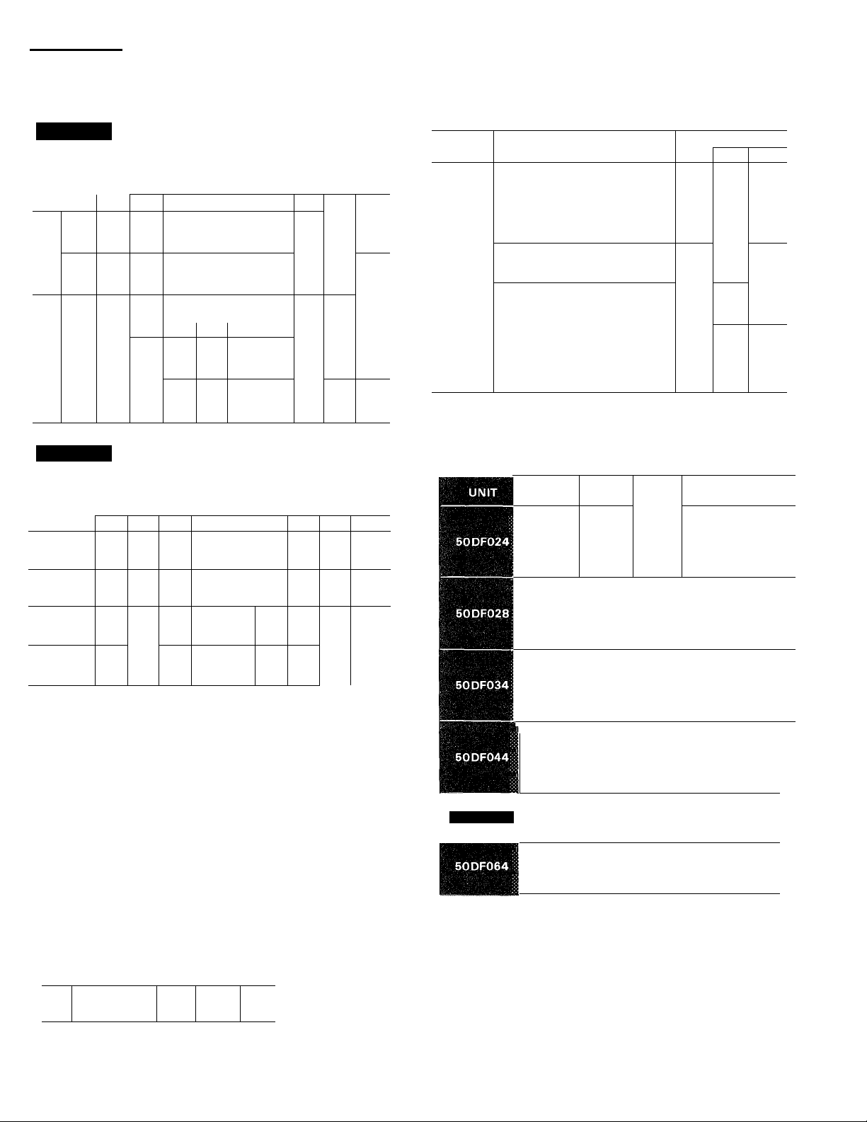
I 50DF~
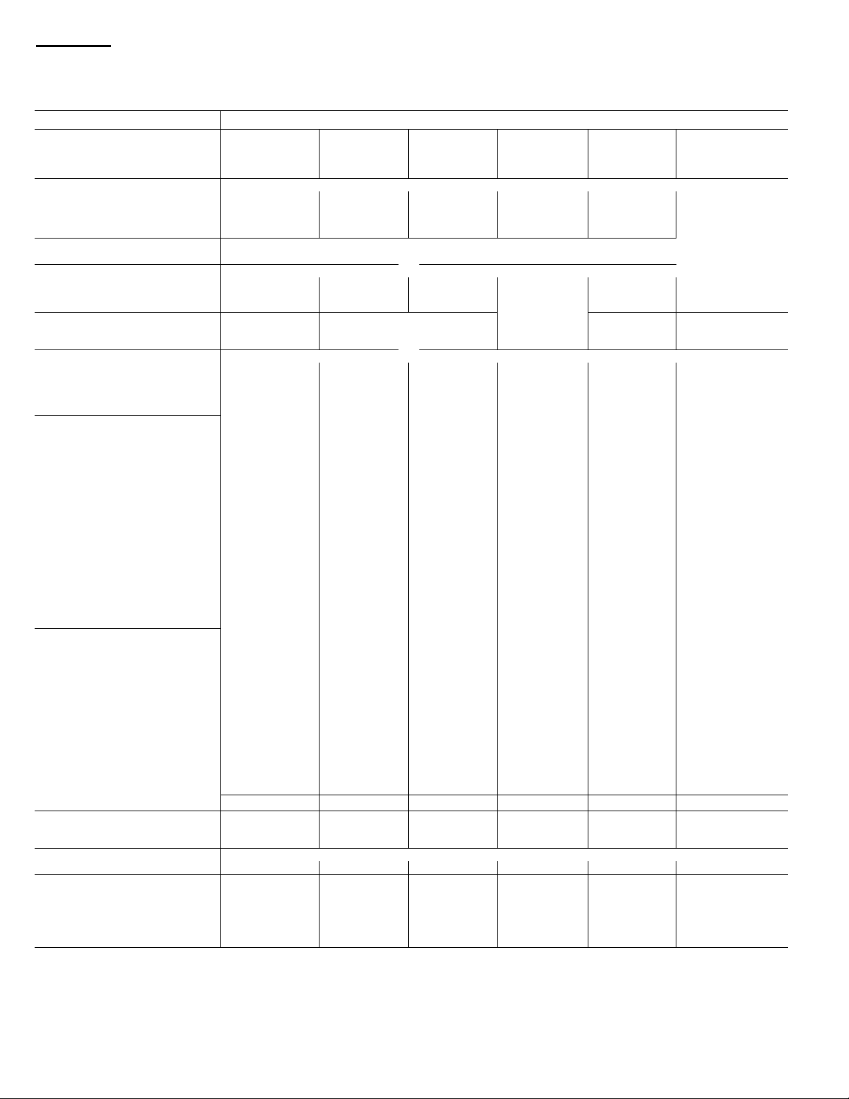
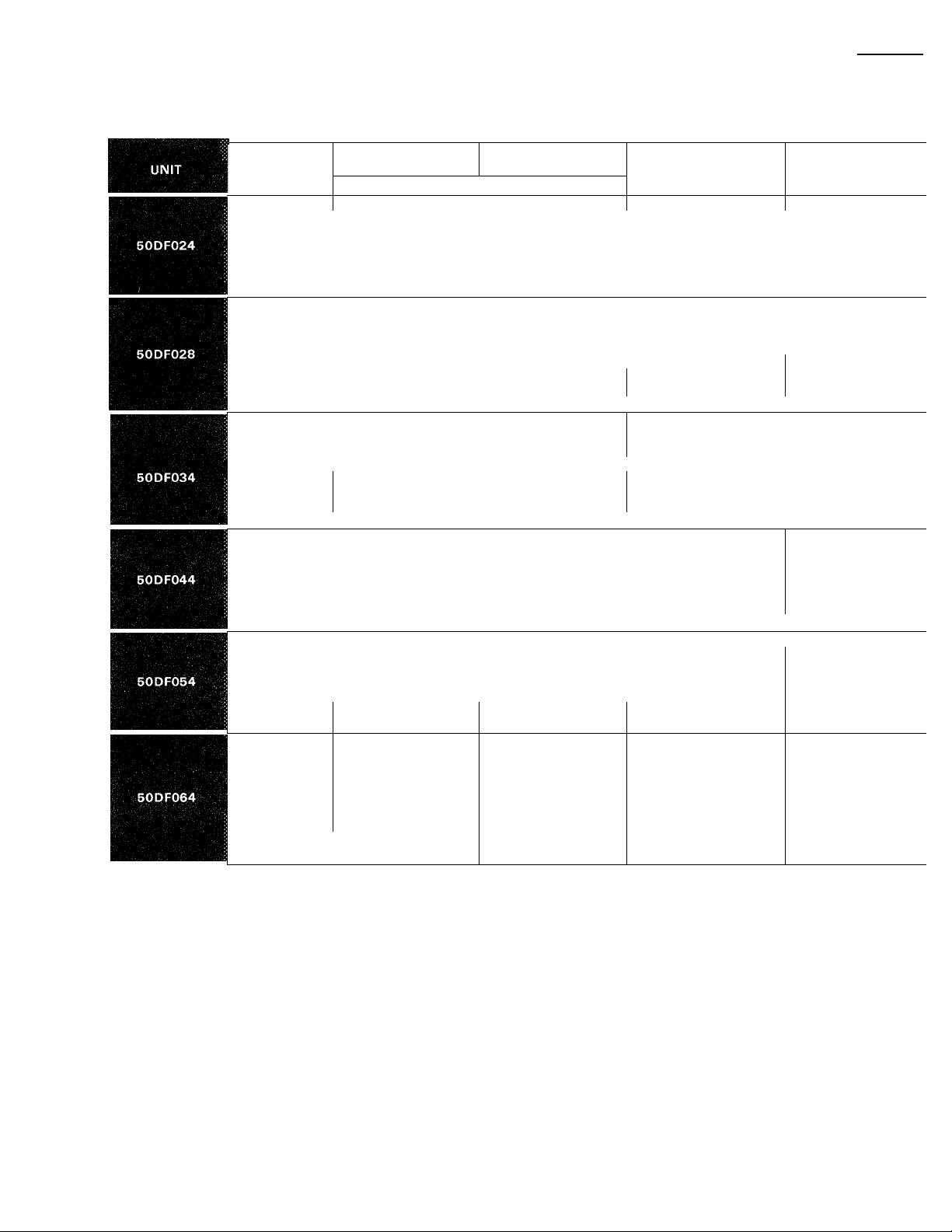
Physical data
UNfT SOOF
OPERATING WEIGHT (lb)
Base Unit
Economizer 150 175 200 225 250
Roof Curb
COMPRESSOR
No ..Type
No Cylinders (ea)...Rpm
Capacity Steps (%) (Std)
With Accessory Unloaders
REFRIGERANT CHARGE Type 22; Controlled by Thermostatic Expansion Valve
Sys 1...Sys 2 (lb)
OUTDOOR AIR FANS
No ...Diameter (in.)
Nominal Cfm
Motor Hp...Rpm
CONDENSER COIL
Rows.. Fins/in.
Total Face Area (sq ft)
INDOOR AIR FANt
No. ...Size (in.)
Max Allowable Rpm
Nominal Cfm
Standard Motor and Drive
Motor Hp
Motor Frame Size
Single-Speed
Two-Speed
Fan Pulley Pitch Diam (in )
Fan Pulley Bore
Single-Speed Motor Rpm
Two-Speed Motor Rpm
Motor Pulley Pitch Diam (in.)
Pulley A
Pulley B
Resulting Fan Rpm
Single-Speed with Pulley A...B
Two-Speed with Pulley A.. B
Alternate Motor and Drive
Motor Hp
Motor Frame Size
Single-Speed
Two-Speed
Fan Pulley Pitch Diam (in.)
Fan Pulley Bore
Single-Speed Motor Rpm
Two-Speed Motor Rpm
Motor Pulley Pitch Diam (in.)
Pulley A
Pulley B
Resulting Fan Rpm
Single-Speed with Pulley A...B
Two-Speed with Pulley A...B
EXHAUST FAN MOTOR Qty...Hp
EVAPORATOR COIL
Rows...Fins/in.
Total Face Area (sq ft)
ELEC RESISTANCE HEATERS
Heat:Kw
INDOOR AIR Filters
No .. Size
Standard; 2-In Throwaway
Bag Type; 12-in. (Opt)
02A
3000
125 150
1 06E 2 060
4 1750 6 1750
50,100 60,100 50,100
—
36 0 —
2 30
14,000
1 1050 1 1050 1 1050 1 1050 1 1050 1 1150
3 139 3 139
31 1
2 15x11 2 15x15
1300
8,000 10,000
5 (460V)
7-1/2 (208-230V)
184T (460V)
213T (208-230V)
215T (460V)
254T (208-230V)
106 106
1 -3/16
1750
1750/1170
65
60 56
1073 991
1073/751
991/661 925/617
7-1/2
213T
254T
80
1-3/16
1750 1750 1750 1750 1750
1750/1170
53 5 3
56 56
1159 1225
1159/773 .
1225/817 1225/817
1 3
4 15
15 1 177
37,55,91
6 20x25
6 15x25
3 12x24 4 .12x24
3 24x24 4. .24x24 5. 24x24 6 24x24
028
3700 4400
19,38,57,100 16,33,50,100
23 75 18 25 29 0 29 0 37 0 37 0
2 30 3 .30 3 30 4 30
14,000 21,000 21,000 28,000 31,000
38.0
1300 1300 1300 1300
7-1/2
21 3T 21 5T 254T 256T
254T
1-3/16
1750 1750 1750 1750
1750/1170 1750/1170 1750/1170
65 6 5 65 6 5 5 6
1073 925 1073 925 1073 925 1073. 925 1225 1312
1073/751. 1073/751
10
215T 254T 256T 284T
256T 284T 286T 286T
80 80 80 80
1-3/16 1-11/16 1-11/16 1-11/16
1750/1170
1159 1225 1159 1225 1159 1225 1159 1225
1159/773 1159/773 , 1159/773 1159/773
1 3 1 3 2 3 2 3 2. 3
4 15
Open Nichrome Wire Elements with Multiple-Stage Control
55,73,110 55,91,128
18. 16x25
034
175
Serviceable, Hermetic
2 06D
6 1750
Direct Driven, Propeller Type
3 158
49 0
i
Belt Drive, Centrifugal Type
3 15x9 4 15x9
12,000
10 15 20
256T 284T 286T 286T
106 106
1-11/16 1-11/16 1-11/16
5 6
925/617 925/617 991/661
15 20 25t 30t
1750/1170
53 5,3 53
56 5 6
1225/817 1225/817
4 15
24 8
9, 20x25
12 16x25
5.. 12x24
044 054 064
5406
200 225
2 06E
4 1750
50,100
25,50,75,100
3 158 3 158
61 0
16,000 20,000
56
1073/751
1750/1170
4 15 4 15 4 139
30 2 35,4
73,110,165
27.. 16x25
6. 12x24
20,40,60,80,100
1073/751
6100 6485
**
2 06E*
4,6 1750
60,100
53 0 42 0 81 0 81 0
81 5
4 15x11
106
1750/1170 1750/1170
60
1750/1170
56
1225/817
91,146 91,146
9 20x25 9 20x25
21 16x25 21 16x25
7 12x24
7 24x24
250
225
2 06E
6 1750
50,100
16,33,50,67,83,100
4 30
4 158
81 25
4 15x11
1450
24,000
25
284T
80
1-11/16
1750
60
1225/817
1312/875
286T
—
60
1-11/16
1750
1750/1170
50
**
1450 —
1450/967 ,
35 4
_
#
*Unit contains one 06EA250 and one 06EA275 compressor
fStandard fan motor supplied with standard fan drive pulleys and belts;
alternate fan motor supplied with alternate fan drive pulleys and belts Other
combinations are field supplied Pulley A is installed in unit; pulley B is shipped
with unit (024-054)
itDue to large frame size, the 25 hp, 208-230 volt and 30 hp motors are avail
able in single speed only
**The 50DF064 alternate drive Is supplied with Pulley A only
1182
Page 7
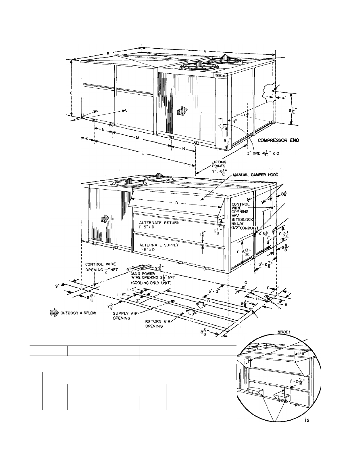
Base unit dimensions
ELECTRIC
HEATER
ACCESS
panels
50DF
OUTDOOR AIR FANS:
2- 024.028
3- 034,044
4- 054, 064
ALTERNATE
CONTROL WIRE
OPENING CONDUIT
ALTERNATE PIELO POWER WRING
ICOOLiNG ONLY UNIT)
a®OOR AtR FAN
AND FiLTEB
ACCESS PANELS
©»«PRESSOR
END
INDOOR AIRFLOW
DIMENSIONS (ft-in.)
UNIT
50DF
Cenified dimension drawings available on request.
NOTES;
1. Allow 12 ft above unit 8 ft on filter access pane! erxland 4ft on remaining sides of unit for
2 For smaller clearances, contact Carrier.
3 Refer to Roof Curb dimensions for details of roof openings
024
10-10
A
8
C
4-11
D
0-10-1/4
E
0- 9-7/8 0- 9-7/8 ¡0- 9-7/8 1- 1-1/4
F
6
H
J
K
L
M
N
airflow arwJ service clearance.
—
—
3-1/2" NPT
2- 4 2- 4 ; 2-10 2-10 2-10
6- 1-1/2 9- 0 ; 11- S :14-10-1/2
—
~
028 I 034 I 044
13- 8-1/2‘1 17- 1 ['20- 6-1/2
6-11 ■ 9-0 i 11- 0
0-10-1/4 i 0-10-5/16 0-10-5/16
4" NPT i 4" NPT 4“ NPT <ea)
— 1 — ¡4-7
7-3-1/8
4-11
— — 0- 9-3/16
— i — 1- 8-1/4
— Î — 1 5- 8-1/2
054
24-11-1/2 24-11-1/2 \
13- 0-1/2
0-10-5/16 0-10-5/16 1
1- 3
0- 9-1/8
1-10-11/32
4" NPT (ea)
19- 3-1/2
7- 7-1/2
5-10
19- 3-1/2
9- 4-1/2
Q04 AIR INTAKE HOOD
1- 3 1
2-10
6-10
OPTIONAL
13- 0-1/2 li
0- 9-1/8 \
1-10-11/32 V
4" NPT (eal V
DRAIN
2|" DiAM U"
*^MPT C0NN.,i.
alternate
drain 2~“ KO <r HURT
MAIN POWER WIRE
OPENING <J) CHEATING/
COOLING UNIT', (2ON
044,054 AND 064)
OPTIONAL JS-034
EXHAUST HOO0SÌ4-O44
CONN. iNStOE)
ALTERNATE
POWER WIRE
OPENING 3^"NPT
GCATING/COOUNG
" UNITK2 ON
044.054 AND
064)
ENTHALPY
CONTROL
LOCATION
{5-054,064
-024,028
Page 8
50Df1
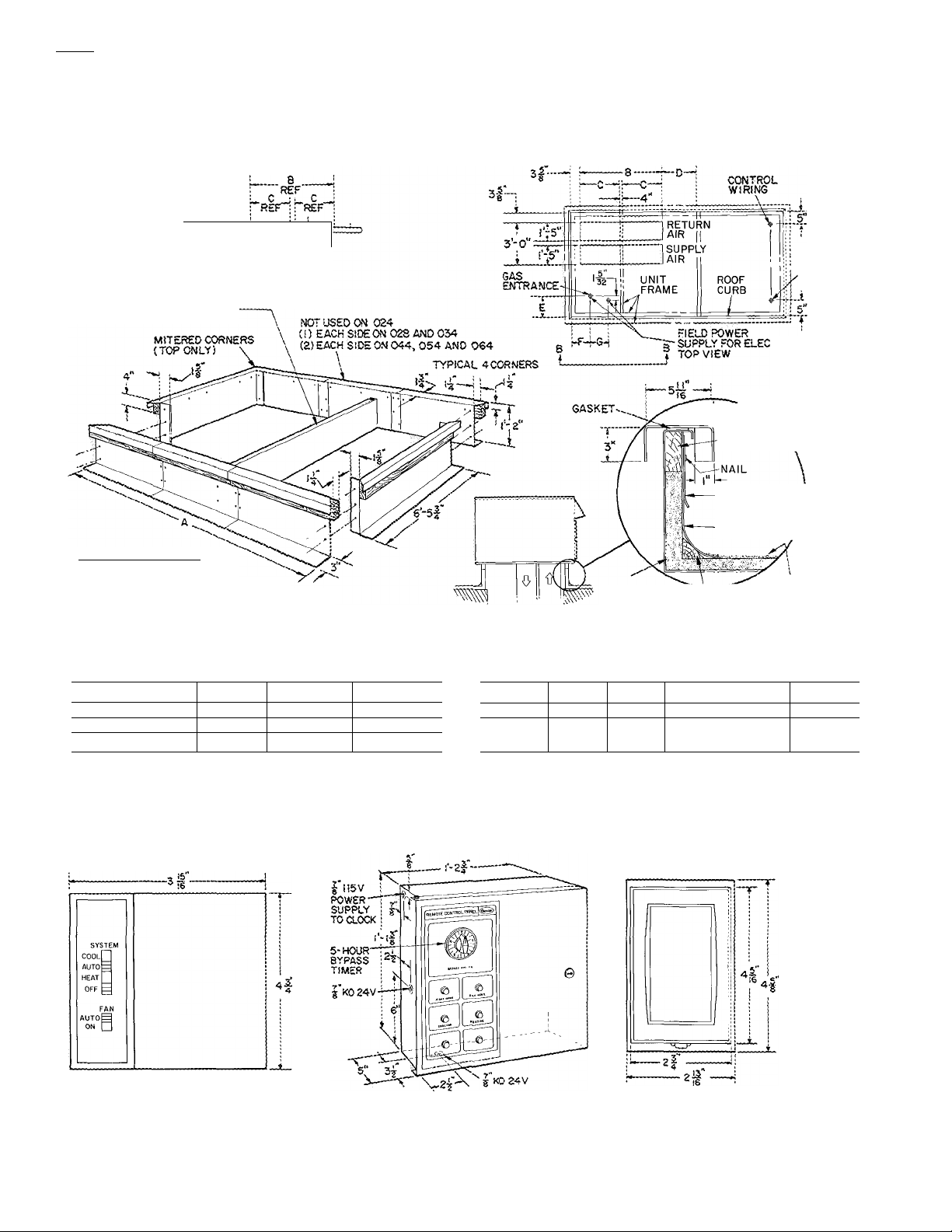
Accessory dimensions
DUCT WORK (FIELD
SUPPLIED) MUST BE
NOTCHED TO CLEAR
SUPPORT
NOT USED ON 024.028
(LOCATE PER DIMENSIONS)'
ROOF CURS ASSEMBLY
NOTE:
CURB MUST BE LEVEL SO THAT UNIT
DRAINS FUNCTION PROPERLY
SEE BASE UNIT INSTALLATION INSTRUCTIONS
FOR LEVELING TOLERANCES
■ 5*i"
V1EW8-B
VIEWA-A
DIMENSIONS (ft-in.)
RIGID
INSULATION
(FIELD SUPPLIED) \
FIELD
POWER
SUPPLY
HEAT UNITS
TYPICAL 4 SIDES
ILTi^v^r-UNIT BASE
Jr \ RAIL
WOOD NAILER
(FACTORY SUPPLIED)
COUNTER FLASHINS
(FIELD SUPPLIED)
ROOFING FELT /
(FIELD SUPPLIED)
ROOFING MATERIAL
(FIELD SUPPLIED)
CANT STRIPiFIELOSUPPl
.lEO)
UNIT A
50DF024 ;10- 0-1/4
50DF028 ;12-10-3/4 : 6-11
50DF034 Ì16- 3-1/8
; 8
; 4-n
; 9- 0
SU^ASE
c D E
: „
i “
; 4-4
0-6-1/4
0-6-1/4
0-6 0-8-1/4 0-6-7/8 i -
F : G
0-5-1/8 : —
0-5-1/8 i -
UNIT
50DF044
S0DF054
50DF(^
REMOTE CONTROL PANEL
(Control Box)
A B i c O E F
19-8-1/4 11-0 15-4
24-1-3/4
13-0:6-4
THERMOSTAT/TRANSMITTER
0-6 :0-6-1/4 ;6-9-1/4
0-6 10-6-1/4 iO-6-3/4
G
0-7
0-7-11 /32
n
1182
Page 9
SctectlOîî procedure (with example)
1 Determine cooling and heating requirements at design SHC of 236,000 Btuh. Calculate SHC correction, if
conditions. required, using notes under cooling capacities tables
Given III Select heating capacity of unit to provide design condi-
Required Cooling Capacity (TC)
.......................
300,000 Btuh ^ion requirement.
Sensible Heat Capacity (SHC) ............................ 236,000 Btuh In the Heating Capacities table, note that unit 50DF028 with
Required Heating Capacity
Condenser Entering Air Temperature ........................... 95 F c j j •
Indoor Air Temperature ....
Evaporator Air Quantity......................................
External Static Pressure
Electrical Characteristics (V-Ph-Hz)
................................
...................
80 F edb, 67 F ewb Determine fan speed and power requirements at design
.......................................
..............
240,000 Btuh 73 kw heaters will provide 249150 Btuh
10,000 cfm conditions.
1 80 in wg f^an Performance table at 10,000 cfm and 1 80 in wg
460-3-60 ^^at the fan speed is 1210 rpm and the power required is
II Select unit based on required cooling capacity >^P
Enter Cooling Capacities table at condenser entering ^ Select unit that corresponds to power source available,
temperature of 95 F Unit 50DF028 at 10,000 cfm and 67 F The Electrical Data table shows that a 460-3-60 unit is available,
ewb will provide a total capacity of 308,000 Btuh and a
Performance data
COOLING CAPACITIES
50DF024
m
Temp (F)
Air Ent
TC 266
85
SHC 132 165 197
KW 21.3 20.1
TC 250 228 206
95
SHC
KW 22.6 1 2l;6 20.1
TC 243 221
100 SHC 124
KW 23 2 22 2
TC 236 214
105
SHC
KW
TC 227 207
110 SHC 119 151
KW
6000/.042
72
127
122
23 9 22 6 21 4
24 8 23 2
50DF034
Temp (F)
Air Ent
Cond
TC
85 SHC 214
TC
95
SHC 203
TC
100
SHC
TC
105
TC
110
10,000/.068 12,000/.082 | 13,500/ 088
72 67
412 380
KW 32 0
392 360
KW 34 7
383
200 255
KW
35 9
373 344
SHC 197
KW
37 4
354
SHC 191
KW
39 3 37 8
67 62
243 220
19 0
159 191
201
157 189
20 7
195 247
154 186
188
183
22 0 25 3
62
349 424
266
321
30 7 29 3
332
258 315
33 4 31 5
352
323
311
34 6
32 6 37 1
316 384
252
308
35 8
34 2
326
299
245
299
36 0 39.9
Evap Air — Cfm/BF
; SOOOAOy
Evap Air — Ewb (F)
72
278 255 233 283 260 237
147
22.0 20.8
263
142
23.4
255
139 182 212
24 0
137
24.6
238 216
135 176
Evap Air — Cfm/BF
Evap Air — Ewb (F)
72 67
226 292
33.2
401 370 342
218
35.3 33.8
392
214
211
38.1 36 2
363
206
____
{
9000/.070
67 62 72 67 62
191 231 157 206 237
239 218
184
22.0
232 212 260 236 216
22.8 21 4
225
179 206 147 192
23.4
24 1
391 360 430 397 366
31.5
283 342 231 303 347
361
280
35.0 33 2 37 5 35 7 33 6
353 325 390 358
278 325 222 297 330
335
271
38 3 36.6 40 5 38 5 36 9
22.4
19.6
218
20.8 23.7 22.5 21.1
206
22.1
198
198
22 5
62 72 67 62
356 240 311 366
29.7 33.5 31 8 29 9
31.8
334 399 367 339
334
34 6
308
308 215
21.1
243 222
268
153
198
150 196
23 1 21 7
24 3
251 229
23.7
24.9
241
220 202
144
189 202
25 6 24 4
376 347
408
34 4
36 2
227
300 339
38 7
36 8
370
340
291 312
50DF028
Temp (F)
Air Ent
TC 345 318
85
20.0
222
216
210
210 105
22.3 KW
22 8
SHC 178 229
KW
TC 330 303
95
SHC
KW 31 2
TC 320 295 271
100
SHC
KW 32 7 30 4
TC 310 286 263 315
SHC 168
TC 300 277 255
110
SHC
KW
9000/.058 ! 10,000/.068~T 11,000/ 074
72
67 62
294
29.5 27.8 26.2
174
171
34 0 31 7 29 9
165
35 3 33 1 31 0
278 185
278
272
223
27.7
29.3
220 268
29 0
216
263 176
255 171
213
50DF044
Temp (F)
Air Ent
85 SHC 281
95 SHC 269 345 419
32 4
100
330
105 SHC 258 333
34 8 KW 49 2 46 6 43 6
312
110 SHC
14.000/051 ^ 16,000/.062 i 18,000/.070
72 67 62
TC 538 499 457
KW 43.7 41 8
TC
KW 46.8 43.7 41.0
TC
SHC
KW 47 9 45 0 42 5
TC 475 436 397
TC
KW 50 8 47 9 45 2 51 3
357
436
39 5
506
465 427
491
263 339 411
458 419 380
252
411
450
397
326 380 269
Evap Air — Cfm/BF
Evap Air — Ewb (F)
72
67 62
351 322
242
28 2 25.4
30.0
335 308 283 339 312 287
236
181
31.4
29.5
325
299
233
178
33 1
30.8
290
229
34.4
32 1 30.2
281
305
226
33 4
35 5
Evap Air — Cfm/BF
Evap Air — Ewb (F)
67
72
507
549
295 383 468
45.1 42.5 33.8
516 475 436
285 369 436 301
47.1 44,5
499
460
364
280
45.6
48 3
444
483
275
358
49.8 47 1 443
■427"
'465"
353
48.5 46.0
72 67
355 327 302
298
296 194
283 190
28.2 ! 31.7 30.1 28.5
275
275
29 2
267
267
259
259 180 239 262
31 2
62
468
41 8 47 5
420 506 466
420
43 1 48 7
405 490
405 290 383
"388‘
388
253 302
30.2
28 4
248
329 303 279
187
245 279
31 3 29 6
33 3
294
318
183
242
24 7 32 3
284
309
35 7
33 6 31 7
72 67
558 515 476
408 476
312
45 4 42 9
524
481 445
394
45 0 42 7
295 390 428
46 2 44 1
450
50 6 47 5 45 2
473 433
377 395
283
51 7 49 0
62
26.6
287
270
270
30 5
262
62
40 6
445
428
412
412
395
46 8
Page 10
ПорП
Performcince data (cont)
COOLING CAPACITIES
60DF054
Temp (F)
Air Ent
18,000/ (^8~T2ao6oZo6S ] 22^000/.073
72 67 62
TC 686 639 596
85
SHC
361 462
KW 56 3 53 2
TC 650 602 558
95 SHC 347 446 546
KW 61 1
TC 629
57 6
581 538 637
100 SHC 340 438 538
105
KW
TC
SHC 333
KW
59 0 56 3
63 1
608 563 518
432
61 4
51 0
TC 589 540 496
110 SHC
325 423 496 344
KW
—
63 8 60 3
Evap Air — Cfm/BF
Evap Air — Ewb (F)
67
565
50 4
72
636 648
376 485
57 6
54.2 50.7 58 6
72 67
62
604 704 654
392
600
659 610 566 666 616 572
472
363
53 8
61.5 57.8 53.7 62 2 58 8 54 7
589
354
465
63.7
59.8
380 499 572
566
644
545
371
545
56.6 64 3 60 2 56 9
616 570 525 622
518
58 1
457
348
61 6 584
—
597 546
448
64.2 60.5
—
525 365 483
—
604 552
502
502 359 475 510
—
514
54 5
597
493 552
576
62 1
64 8
50DF064
Evap Air — Ewb (F)
55 9
600
59 6
63 4
562
1 09 X cfm
Evap Air — Cfm/BF
67^
72 :
807 ; 744
432 : 553
62.4 j
766;
418 i
66.8'
718
400 521
70.9672
74.9 i
SHC — Sensible Heat Cap
TC — Total Cap (1000 Btuh) Gross
684
658
59.4
56.6
70Г'
649
536
635
63.4
60.4 67.2 62.7
663
612
609
67.4
64.3
617
576
576
71.1
68.1
(1000 Btuh)
62
72
67
820
753 696
449
579 683
63
59.9 57 1
775
714
433
563
726
671
416
546
71 4
67 8
678 624
399 526
75 4
71 6
Temp (F)
Air Ent
Cond
85
95 SHC
105
115 SHC 365 471 556 384 • 502
BF — Bypass Factor
Ewb — Entering Wet-Bulb
KW — Compr Mtr Pwr Input
NOTES;
Direct interpolation is permissible Do not extrapolate
The following formulas may be used.
f|db fedb
f|wb
h|wb = hewb
Where:
hewb" Enthalpy of air entering evaporator coil
SHC is based on 80 F edb temp of air entering evaporator coil Below 80 Fedb,
subtract (corr factor x cfm) from SHC
21,000 / .070 i 24,000 / .081 26,400 / .090
72
67 62
TC i
796 731 669
413 521 620
SHC
KW 61 9
TC 751 693 634
KW
TC 709 650 598
SHC 387 487 579
KW 70 3 66.6
TC
58.8
397 505
66 0 62 8
665 609
KW 74 3 70 5 67 0
sensible capacity (Btuh)
Wet-bulb temperature of corresponding to enthalpy of air leaving
evaporator coil (h|^p)
total capacity (Btuh)
------------
------------------
612
612
51 6
552
532
532
58 7
510
60 9
62
660
657
61.1
624
624
65 8
591
591
71 9
62
OPTIONAL EQUIPMENT RESISTANCES (in. wg)
UNIT
MODEL
50DF
024044
50DF
054
50DF
064
OPTION
Bag Filter
Economizer
Economizer with Exhaust
Electric Heaters 0 5:1 (Low) 06
(Heat Cool Ratio)0 75 1 (Med)
1.0.1 (High)
Bag Filter
Economizer
Economizer with Exhaust
Electric Heaters 0 5:1 (Low) 12
(Heat: Cool Ratio)0 75 1 (Med)
1 0 1 (High) 22 39 61
Bag Filter
Economizer
Economizer with Exhaust
Electric Heaters 0 5 1 (Low)
(Heat Cool Ratio)0 75:1 (Med) 24 44
UNIT CFM/TON
Г3ОО 400
14
03 05
.09 .15 .23
09 15 23
.14
14
03
.11
15
20 36 55
04 07 11
13 21
18 35
HEATING CAPACITIES
50DF054 ■
VOLTS
(Nominal)
208-230
460
208-230
460
208-230
30-37
I 37
; 45-55
1 75-91
460
208-230
460 i 55 ^ 67
208-230
460
208-230
460
208-230
460 55 ; 67
208-230
460
208-230
I 460
208-230
460 i 73 ;
208-230
460 1 110
208-230
460 ; 165
208-230 i 75-91
460 ; 91 ;
208-230 120-146 :
460 ! 146
208-230
460
208-230
460
' 45-55
1
60-73 ! 50
; 73
30-110 ' 50
i 110 : 50 375,430
1 45-55
i 75-91
; 91
Ì105-128 1 57
; 128 57 436,865
! 60-73
190-110
135-165 1
1
75-91
i 91 ; 60 310,585
0 20-146 , 50
; 146 50 : 498,300
STAGE
KW ^
55
91
1%
’50
; 50
: 67
; 67
, 60
i 60
1 67
50 249,150
i 67
! 60 255,975-310,585
i 60 310,585
1
50
50
1
50
50 ! 375,430
56
56
1
66
60 ;■ -310,585
50
50
66
1
102,390-126,280
; 126,280
1153,585-187,715
; 187,715
255,975-310.585
1153,585-187,715
¡204,780-249,150
1307,170-375,430
153,585-187,715
358.365-436,865
1204,780-249,150
i 249,150
1307,170-375,430
¡460.755-563,145
: 563,145
255,975-310,586
409,560-498,300
1255,975-310,585
¡409,560-498,300
25 38
09
.25 .35
25
04
.15 .24
23 38
30
BTUH
310,585
187,715
187,715
498,300
500
08
13
38
08
46
31
54
68
9
Entering Air Dry-Bulb Temp (F)
BF
Correction Factor
.05 1.04 2 07 3 11
.10
.20 87
Interpolation is permissible
Correction Factor = 1.09 x (1 - BF) x (edb - 80)
4 Cooling capacities are gross and do not include deduction for indoor fan
motor heat
98 1 96
2 94 3 92
1 74 2.62 3.49
4 14
5 18
491
4 36
use formula
shown below
1182
«
10
Page 11
INDOOR AIR FAN PULLEY DATA
50DF I
FAN
RPM
925
931 2~3V—6.0
1073 2—3V—6.5
TÓ93
1159
1225 2—3V—5.6
1300 2—3V—6 0
925
984
1073 2—3V—6.5
1093 2—3V—5 0
1139 2_3V—6 9
1159
1225 2—3V—5.6 3_3V— 8.0
1300
925 2—3V—5.6
991
1073
1093 3—3V—5 0
1141
1159
1225
1300
925 4—3V—5.6
991
1073
1093 4—3V—5.0
1159 5—3V—5.3
1225
j 1300
1 925 4—3V—5 6
991
1039
1073
1093 5—3V—5 0
1159 5~3V—5.3 5_3V— 8.0
i 1225
1 925
I
1 1039 5—3V—4 75
1 1073 4—3V—6 5
1 1093 5—3V—5 0
1 1159
1 1225 5—3V-5.6
1 1312
I 1450 1 5—3V—5.0
MOTOR
PULLEY
No. Grooves—Type—in.
2—3V—5.6
2—3V—5 0
2—3V—5.3
2-3V-5.6
2—3V—4 5
3—3V—5.3 3~3V— 8.0
2—3V—6 0
2—3V—6 0
2-3V—6.5
4—3V—4.5
4—3V—5.3
4—3V—5.6
3—3V—6.0
3—3V—6.0
4—3V—6.5
4_3V~5.6 5—3V— 8.0
4—3V—6 0
4-3V-8.0
5—3V—4.75
4—3V—6.5
5-3V—5.6
4—3V—5 6
4—3V—6 0
5—3V—5 3
5_3V—6.0 5—3V— 8.0
FAN
PULLEY
2—3V—10.6
2—3V—10.6
2~3V—10.6
2—3V~ 8.0
2-3V— 8.0
2—3V— 8.0
2—3V— 8.0
2—3V—10.6
2—3V— 8.0
2-3V—10.6
2—3V— 8 0
2-.3V—10.6
2—3V— 8 0
2—3V—10.6
2—3V—10.6 2—3V—750
2—3V—10.6
3—3V— 8 0
4-3V— 6.9
4~3V— 8.0
4—3V— 8.0
3—3V— 8 0
4—3V—10.6
3_3V—10.6
4-3V—10.6
4—3V— 8 0
5—3V— 8.0
4—3V— 8 0
4—3V—10.6
4—3V—10.6
5-3V— 8.0
4-3V—10.6
5—3V— 8.0
5_3V— 8.0
4—3V—10 6
4—3V—10 6
5—3V— 8 0
4—3V—10 6
5—3V— 8 0
5—3V— 8.0
5—3V— 8.0
5-3V— 6.0
SINGLE-SPEED
BELT
NO.-SIZE
2—3V—710
2_3V~750
2-3V—750
2—3V—670
2—3V—670
2—3V—670
2—3V—710
2—3V—670 1
2—3V—750 : 2—3V—750
2—3V—710 i 2—3V—710
2—3V—750 ■ 2—3V—750
3_3V_710 2_3V~710
3_3V_710*
2—3V—710 i
2—3V—750
2—3V—750
3—3V—710
4—3V—670
4—3V—710
4—3V—710
3—3V—710
3—3V—750t
3—3V—750
3_3V_750t
4—3V—710
5_3V—710
5_3V_710*
4—3V—710
4~3V—750
4—3V—750
5—3V—710
4—3V—750
5—3V—710
5_3V_-710
5—3V—710
4—3V—750
4—3V—750
5—3V—710
4—3V—750
5—3V—710
5—3V—710
5—3V—710
5_3V_-710
5_3V—670
2-3V—750 i
TWO-SPEED
BELT
NO.—SIZE
2—3V—710
2—3V~750
2~3V—750
2—3V—7i0
2—3V~710
2—3V—710
2—3V—750
2—3V—750
2—3V—670
3—3V—710
2—3V—710
2—3V—750
i 2—3V—750
2—3V—750
3—3V—670
4—3V—670
4—3V—710
4—3V—710
1 3—3V—710 ■
3_^V—770
3—3V—770
3—3V—770
4—3V—710
5—3V—710
5-3V—710
1 4—3V—710
4^V—750
4—3V—770
5—3V—710
4—3V—770
5—3V—720
5—3V—720
5--3V_720
4—3V—750
4—3V—770
5—3V—710
4—3V—770
5—3V—720
5—3V—720
5~3V—720
5—3V—720
—
Shaded values indicate standard or optional pulley combi
nations available as shown in Physical Data table All
other combinations are field supplied
‘Remove one belt.
fDrive requires 3 belts; 4 belts may be used if desired.
11
Page 12
50DF
Performance data (coni)
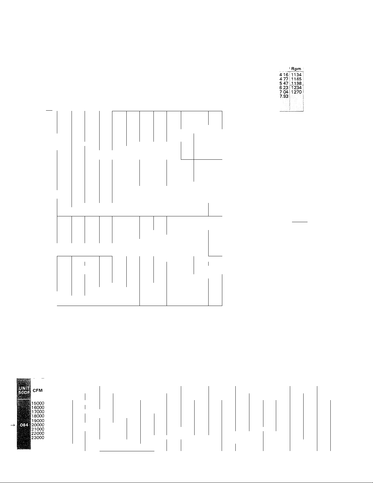
FAN PERFORMANCE
CFM
6000
6500
7000
7500
8000
8500
9000
9500
110000
7500
8000
8500
9000
9500
10000
10500
11000
11500
12000
112500
9000
9500
10000
10500
11000
11500
12000
12500
13000
13500
14000
14500
15000
12000
13000
14000
15000
16000
17000
18000
19000
20000
15000
16000
17000
18000
19000
20000
21000
22000
23000
24000
25000
Bhp — Brake horsepower
Rpm — Revolutions per minute
NOTES:
1 Values in italics indicate that motor larger than optional fan motor is required
2 Fan performance has deductions for unit casing losses, wet coil and clean
standard filters
3 Fan motor bhp is based on minimum voltages and 80 F air across motor
0.20
Rpm I Bhp
699
1 72
2 12
746
794
2 59
3 13
843
3 74
892
4 42
941
991
5 19
1041
6.04
6.99
109
662
1 78
696
2 09 763
730
2 43
2 81 829
764
3 22
799
834
3 68
4 20 929
870
4 70 963
905
941
5 30
977
6 00
6.70
1013
2 86
690
3 29
720
3 76 813
751
782
4 28
814
4 80
5 50 901
845
877
6 10
6 80
909
7 60
941
8 50
973
1006
9 40
1038
10 30
1071
11.30
734
4 80
6 00
791
7 40
848
907
9 10
11 00
966
1026
13 30
15 70
1086
1147
18 50
1208
21.70
704
5 08
741
6 00
7 02 843
779
817
8 17
9 44 915
855
894
10 84
12 38
933
14 06 1025
972
1590
1011
1790
1051
20 05
1090
Alternate fan motor or drive is required
Field supplied drive required
0.40 0 60
Rpm
Bhp
2 04'
763
807
2 48
852
2 97
897
3 54
943
4 17
990
4 89
1037
5 68
1085
6 56
1133
7 53
2 25 791
731
2 60 820 3 07
2 99 851 3 49 905
796
341 883 3 95 933
862
3 87
895 4 37 948
4 90 981 5 60
5 50 1014 6 20 1059
997
6 10
1031 6 80 1080 7 70
1065 7.60
755 3 40 812
784
3 88
4 40 867 4 97 917
4 96 895 5 57
842
871
5 60
6 20 952 6 90
931 7 00 981
962 7 70 1010 8 50'1055
992 8 50 1039 9 40 1083
1023 9 40
1054
10 40 1099
1085 11 40
1116
12.40 1159
784 5 40 838 6 20
831 6 60 883
880 7 90 928 8 80
932 9 50
985 11 40
1040 13 50 1071
1097
1590 1122
11S4
13 60 1175
1212 21,70 1229 22.20 1255
772
6 10 829
807 7 13
8 26 898
878 9 51 933
10 87
951 12 37 1003
988 14 00 1038 15 50
15 77
1062 17 69
1100
13 78
1138
22 03
Bhp
Rpm
820
862
905
948
992
1037
1082
1128
1174
915 4 46 963
1047
1114
839
923 6 20
1069
1129
974 1040
1022
863
968
1074 17 37
mo 1940
1147 21 58 1190 23 27
1183 23 92
Rpm
872
2 34
912
2 81
3 34
953
3 94
995
1038
4 60
5 35
1081
617
1125
1169
7 08
1214
8.08
2 71
848
877
5 01 994
1027
6 90 1092
1125
1157
8.40
3 91 865
891
4 42
943
971
999 7 60 1042
7 70 1027
10 30 1112
U41
11 30
1170
12 30
1200
13.50
889
930
7 40
974
1019
1064
12 20
14 30
1170
1157
16 60
19 20:1205
6 94 882
913
8 08
9 32 946
10 68 980
12 16
1015
13 76
1050
1084
1119 1884
1155
1226
EXTERNAL STATIC PRESSURE (in. wg)
0.80
Bhp
2 64'
3 13
3 69
4 32
5 02
1080
6 79
6 65
7 59
8.62
3 21 904
3 60 928 4 15
4 03
4 49
5 01
5 59
6 20 1069 6 80 1113
690
7 60
S.40 1165
9.30
4 42
4 95 940
5 53 964
6 16
6 80 1016
8 40
9 20
1010
11.10
12 10 1181
13 20
14.40
7 00 937
8 20 977
9 70 1017
11 40
13 30
15 30
17 60
20.20 1241
23.00
7 80 933
8 93 963
10 24 993 11 21 1039 1225
11 70
13 28 1058
15 00 1092 16 11
16.85 1126 18 07
20 93 1196
25 72
1 00
Rpm
Bhp
922
2 95
959
3 46 11005
999
4 03 1042
1039
469 1081 i
5,42 1121 :
6 23 1162 :
1122
1165
7.12 1203:
1208
803Ì1246:
1?.53.
9.1S\12SS
3 76 956 4 36 1005
4 59
955
5 09
983
1012
5 63
1040 6 20 1085
1100 7 50 1142 8.20
1132 8 30
9 10
1197
10.CX)
4 94 960 5 42
916
5 49
6 09 1010
990 6 75
7 50 1059
8 20 1085
1069
9.00
1097
990
1125
1090 1163 11.60
1153 11 90 1191 12.60
1230
14 10
1203
1238 75.30
7 80
9 10
10 60
12 40
1060
1104
14 30
1150
16 50 tl.8,6Mr.6Q..
1135
18.80
21.40
1388 34.30
871
9 91
1024
12 65
14 30 1100
1161 2017 1199
22.42
24 83
1231
1266 27 39 :1303:28.93
1.20
Rpm j Bhp
969
3 26
3 79
4 39
5 06
5 81
6 65 ;.U8.9.
75711240' 801:1275
a 58 :128Ì i $ OS
5.6? : :
980 4 76
1004
5 20 1052
1029 5 70 1076
1057
6 26
6 87 1127
7 50
1171
900
1202
9,80 1240
1234
10.70
985 6 03
6 67 1051
1034
7 35 1076
8 10
8 30 1125
1110 9 70
1136
1060 1176
1218
1370
^1245
14.90
1275
76.10
987
8 70
1022
10 00
1060 11 60
13 40
1101
1142 15 30
1231
20.00
1276
22.70
983
9 68 1031
1010 1089 1057
1069
1375 1112
15 36
1717
1132
1165 19 19
21 38
23 74
1234
.28,25 1304
1268
1.40
Rpm I Bhp
1012
3 56
1048
4 13
1084 :
4 75
1121 ;
544 1160
6 21 ,1197
1159 :
.7..07.ÌÌ235
4 98
1028
5 40
5 87
6 35
1100
6 92
7 53
1155
8 20
1184
900
1212
, 9J?0
10 60:
1270
11,50;
1006
5 94 11052
1026
6 54'1071
7 22 1091
7 96 1114
1100
8 70 1139
9 50 :1164
nso
1040 :1188
11 30:1213
1230; 1238
1201
13.40:1264
1227
1254
14.50:1290
1282
15.70 :
1034
950 1081Ì1050 1125:11 40: 1169:125Q:1211 :13.70
1068
1100 1110:n 90,1165 12.90: 1195 1390
1102
1140
1181
JU2.1.
,.1S-60
1265
521,10
10 67
11 93
13 31
1083
1484
16 54
1142
1172
18 35
20 32
1203
22 54
1235
24 97
1269
27.58
1333
30 36
1.60
Rpm
l'Ó54
3 85 1094 :
1089
445: 1126:
1125
5 12: 1162:
5.83:1198
5,82] 1234'
7.49
8.46
11054
5 69 1105
11074
6 07
1096
6 55
7 0S
1120
; Ì1144
I :.U22,
1260 1145:1360
14 40 1179'1540
16.40 1217 17,50
1169
•1194
-9,20J1260
(1251
10.50
: 1279
11 40
11 10
12.0Q.Ì1249
13.10
14.10
15.30
lassifg'.sa
1299:122 30
11077 I
11 75
illOl i
12 99
'1127
14 42
15 97
1153
:1181
17 68
■1211
1958
;i241
21 62
.1273:
23ÌàXÌ308
51304;
26.19 :1338
;1337:
28 8S: 1370
Ì1371 :
31.71 :1403
7 63
8.24
390
6 48
7 10
7 77
8.51
930
0 20
1.80
Rpm Bhp
1270
1120
1140
1162
1186
mo.
1234
1236
1094
1114
1133
1152
1174
1200
.1221
1273
1298
1184 1450:1227,1,5.60.
.3220...1.6.50.
1254 518.60
1292.2090
1122
1144
1169
1194
1221
1249
1.2.78
647
6.82
7 26
7.80
8 39
-9.00.
9.70
10.40
11.30
7 02
7 57
8 36
910
990
10.80
.1.1.80.
12.80
13.30
14,90
12 82
14 13
15 54
1716
1889
20.79
.2.2,90.
25.16
27.54
30.13
33,03
2,00
Bhp I Rpm : Bhp
4 48
5 1Cp.202,
,5,.3.lil233
6,60 SI 268
7.46'
1153
7 31
1167
7,64
8 05
1183
8 55
1203
1226
9.15
8.31
1250
1273
10.50
1298
11.20
7.57
1133
8 24
1153
1174
8 97 „1.21.1,
1193
9 73
1212
1.0.50.
1233
11 40(1270
12.40
1258
1284
13.50
1257 ; 17.50
1292 ; 19.70
1166
13 87
1187
15 29
1203
16 75
1234
1834
20 14
1260
22 07
1286
1314
24.17
1343
26.49
1373
28.98
1403
31,59
1434
34 40
2.20
1173 ■
1199
1213
5.222
1244
1254
1237
1173
1190
1232
1250
1291
1237
1266
1295
1206
1228
1249
1272
1.297
1323
1349
1377
1407
1437
4.80
.5.44.
6.15
6.97
8 18
8,53
..8,8.1.
837;
9.83
10,60
8 18
8 81
9 56
10.'37
11.20
12.10
13.10
15.10
16.70
18.60
14 94
1641
17 99
19 61
.21 3.9.
'23.39
:25.S2
527.82
Ì30.36
■33.09
#
0.75
Rpm Bhp
7 56
868
871
901
10 02
935
11 45
963
1004
13 02
14 71
1038
1074
1 6 53
18 50
1109
1144
20 62
24000 1180
25000:1217
22 89
25 32
Alternate fan motor and drive required
1.
Rpm Bhp
934
963 9 90
993
1024
1058 14 30
1092
1126
1161 20 17
1196
1231
1266
60
8 72 996
11 20 1050
12 65 1080
16 1 1 1141
18 07
22 42 1243
24 83
27 40
1.25
Rpm Bhp Rpm
1022
1110
1175 19 47 1222 20 94
1208
1277
1312 ;29.30
1054
9 94
11 16 1079
1106
12 51
1133
140:
15 64 1162
17 44 1191
21 67 1253
1287
24 05
26.59 1320
1355 ;31.04
EXTERNAL STATIC PRESSURE (in. wg)
1 50 1.75
Bhp Rpm Bhp Rpm Bhp
1120 Ilio 12 55
12 46 1134 13 84
1158 15 26 1209 16 75
13 88
1547
1185
17 10
18 96
23 13 1298
25 58
28 22 1361 29.81 1403 31 56 1444
16 88
1212 18 60
20 49
1240
22 56
1269
24 78
27 18
1329
1395
32.70
2 00 2 25
1165 13 85
1186
15 29 1237
1234
18 34 1282
1260
20 16 1307
1287
2210 1332
1314
24 19 1359
1343
26.48
1373
28.95 1415
1434
34 40
12
Bhp
Rpm
1216 15 21 1266 1661 1314
16 67
1259
18 29
19 94
21 71
23 73 1376
25 89
1386
28 20 1429
30 71
33.42
___
2.50 2.75
Rpm Bhp
1286
1307
1329 21 57 1375 23 12 1419 24 71
1352
1402 27 60
Rpm
18 11
1333
19 75
1353
23 40 1396 25 13 1440 26 78
25 37
1420 27 15
1444
29 99
1361
3.Ò0
Bhp
19 54
Bhp Rpm
18 06
19 59 1378 21 12
21 27 1397 22 83
29 32
Rpm
1406
1423
1441
3.
Bhp
21 CM
22 68
24 44
t
Page 13

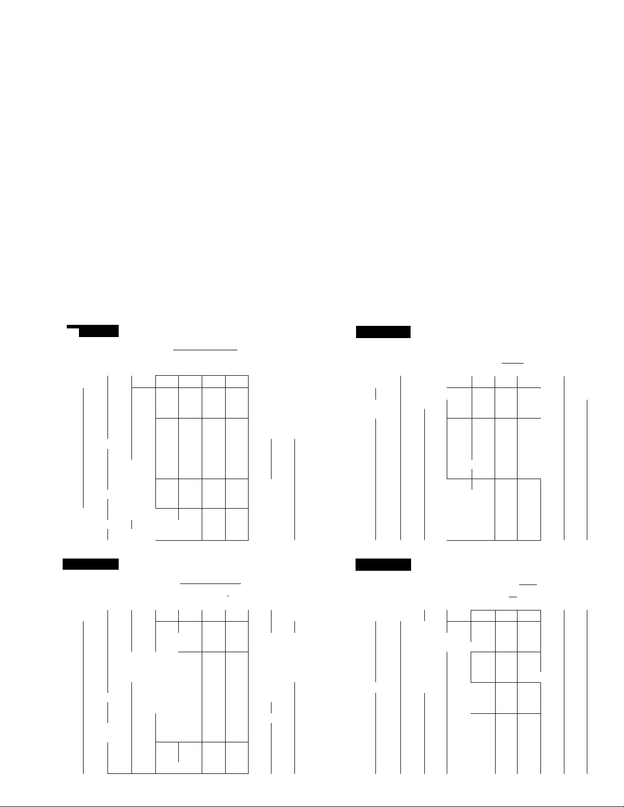
Electrical data
50DF024 and 028
MODEL
NOMINAL
VOLTS/PH/tHZ
50DF024 187
208-230/3/60
50DF024
460/3/60
50DF024
575/3/60
50DF028
208-230/3/60
50DF028
460/3/60
50DF028
575/3/60
COMPR — Compressor
FLA — Full Load Amps
Hp — Nominal Horsepower
Kw — Kilowatts
LRA — Locked Rotor Amps
VOLTAGE
RANGE
Min Max
414
518
187
414
518
254
508
632
254
508
660
COM PR
NO. 1
RLA LRA
80
37 0
30 0
63 5
27 5
22 0
345
173
120
266
120
96
COMPR
NO. 2
RLA
LRA
43
191
193
86
150 69
MCA MOCP RLA —
*Fuse only
OUTDOOR
FAN
MOTORS
Qty
FLA
7 6
(ea)
33
(ea)
2 7
(ea)
7 6
33
(ea)
2 7
(ea)
INDOOR
HP_
7 5
7 5
7 5
7 5
7 5
7 5
7 5
7 5
7 5
7 5
7 5
7 5
7 5
7 5
7 5
7 5
7 5
7 5
7 5
7 5
7 5
7 5
7 5
7 5
7 5
7 5
7 5
7 5
10
7 5
7 5
7 5
10
7 5
7 5
7 5
10
10
10
10
10
10
7 5
7 5
10
7 5
7 5
7 5
10
7 5
7 5
7 5
10
10
10
10
10
10
7 5
7 5
10
10
MOTOR
5
5
5
5
5
5
5
5
5
5
FAN
FLA
24 2
24 2
24 2
24 2
24 2
24 2
24 2
24 2 3
24 2 3
24 2 3
24 2
24 2
24 2
24 2
24 2
24 2
7 6
7 6 3
1 1 \J
1 6
7 6
7 6
11 0
7 6 3
7 6
7 6
11 0
11 0
11 0
11 0
11 0 3
11 0 3
6 1
6.1
9 0
9 0
24 2
24 2
30 8
24 2
24 2
24 2
30 8 3
24 2 3 11
24 2 3 11
24 2 3 11
30 8
30 8
30 8
30 8 3 11
30 8 3 11
30 8
11 0
11 0 3
14 0
11 0
11 0
11 0
14 0
11 0 3 48
11 0
11 0
140
140
140
140
140 3 48
140 3
9 0
90 3 39
11 0
11 0
LEGEND
Minimum Circuit Ampacity
Maximum Overcurrent Protection
Rated Load Amps
EXHAUST
FAN
MOTOR
FLA
—
-
3 11
—
—
—
—
_
11
3
11 30- 36 6
11 45- 54 9
11 75- 91 5
—
—
—
—
—
11
3
3 11
3 11
—
__
48
__
—
—
—
3
48
48 36 6
3 48 54 9
3 48 91
— —
— —
— —
3 48 36 6
48
48 91
—
—
3
3 9
—
— — —
3
3 9
— —
3 11
—
—
—
—
—
11
— —
— —
— —
3 11 90-109 8
48
- —
— —
—
—
3 4 8
3 48
3 48 109 8
—
—
—
—
_
3
48 55
48 109 8 138
— — — —
_
—
3 39
HEATERS
Kw
— —
— —
— —
30- 36 6
45- 54 9
75- 91 5
— —
30- 36 6 83- 92
45- 54 9
75- 91 5
30- 36 6
45- 54 9
75- 91 5
' — —
— —
36 6 46
54 9
91
— —
36 6
54 9
91
54 9
— —
— —
— —
— —
45- 54 9
60- 73 2 166-184
90-109 8
— —
45- 54 9
60- 73 2
90-109 8 249-276
45- 54 9
60- 73 2 166-184
90-109 8 249-276
45- 54 9
60- 73 2 166-184
83- 92
125-138
208-230
83- 92
125-138
208-230
125-138
208-230
83- 92
125-138
208-230
— —
125-138
249-276
125-138
166-184
125-138
125-138
249-276
I I
— —
55 69
73.2
109 8
— —
55 69
73 2 92
55
73 2 92
109 8
73 2 92
— —
— —
— —
NOTES:
1 All outdoor fan motors are single-phase motors
2 All heaters are 3-phase assemblies
3 Circuit no 2 is provided as indicated: total unit MCA equals
the sum of circuit no 1 MCA plus circuit no 2 MCA
FLA
115
115
115
115
_
138
138
138
50DF
POWER SUPPLY*
Circuit
No. 1
MCA
138
138-146
1 87-203
138-146
149
149-149
187-203
149-149
128-146
187-203
138-146
149-149
187-203
149-149
69
46
69
46
69
46
69
92
69
69
154
154
100
158
100
158
160
171
167
187-203
238-261
187-203
178
187-203
238-261
187-203
195-211
246-269
195-211
195-211
246-269
195-211
100
129
187
100
129
187
104
133
190
104
133
190
138
149
60
65
63
67
96
68
67
96
72
72
49
53
52
56
71
76
74
79
57
61
59
63
MOCP
200
225
200
200-200
200-225
200-200
225
225-225
225-225
225-225
200-200
200-225
200-200
225-225
225-225
225-225
90
100
100
90
90
125
100
100
100
125
100
110
150
100
110
150
70
80
80
80
225
225
225
200-225
250-250
225-225
225
225-225
250-250
225-225
225-250
250-300
225-250
225-250
250-300
225-250
90
100
100
110
125
175
100
110
125
175
125
125
175
125
125
175
70
80
80
80
MCA
156-173
156-173
156-173
156-173
156-173
156-173
156-173
156-173
Circuit
No. 2
175-200
1 75-200
175-200
175-200
175-200
175-200
175-200
1 75-200
MOCP
13
Page 14

fsOPF I
Electrical data (cont)
50DF034 and 044
MODEL
NOMINAL
VOLTS/PH/HZ
50DF034
208-230/3/60
50DF034
VOLTAGE
RANGE
Min Max
187
414
254
508
'Ì60/3/60
50DF034
575/3/60
50DF044
208-230/3/60
50DF044
460/3/60
50DF044
575/3/60
518
187
414
518
660
254
508
632
COMPR — Compressor
FLA — Full Load Amps
Hp — Nominal Horsepower
Kw — Kilowatts
LRA — Locked Rotor Amps
COMPR
NO. 1
RLA LRA
63 5
27 5
22 0
80
37 0
30 0
COMPR
NO. 2
RLA LRA
266
63 5
27 5
120
22 0
96
80
345
37 0
173
30 0
120
MCA —Minimum Circuit Ampacity
MOCP — Maximum Overcurrent Protection
RLA — Rated Load Amps
*Fuse only
OUTDOOR
Qty
266
120
96
345
173
120
FAN
MOTORS
INDOOR
FAN
MOTOR
FLA
Hp
10
10 30 8
15
10
10 30 8
10
15
10 30 8 3 11
7 6
10 30 8 3 11 75- 91 5
(ea)
10 30 8 3 11
15 46 0
15 46 0
15
15 46 0 3 11
15
15
10 MO
10
15 21 0
10 140
10
10 140
15 20 0 3
10 140
3 3
10 140 3
(ea)
10
15 21 0
15
15
15
15 21 0
15 21 0
10
10
2 7
15
(ea)
— —
15
15
20
15
15 46 0
15
20 53 5
15
7 6
15 46 0
(ea)
15 46 0 3
20
20 53 5
20 53 5
20 53 5 3
20 53 5
20
15 21 0
15 21 0
20
15 21 0
15 21 0
15 21 0
20
15 21 0
33
15 21 0
(ea)
15 21 0
20
20
20 27 0
20
20
20
15
15
2 7
20 20
(ea)
20 20
EXHAUST
FAN
MOTOR
FLA
Hp
— — _ —
30 8
3 11
__
46 0
— —
30 8
_
— —
30 8
46 0 3 11
—
—
— —
46 0
3
46 0
46 0 3 11 105-128 1 291-322
— — — —
140 3 48
— —
—
—
140
—
3 48
140 3
— —
_
21 0
— —
21 0
21 0
3
3 4 8 91 5
3 4 8 128 1 161
— —
11 0
11 0 3 3 9
—
—
3 39
__
46 0
46 0 3 11
— — —
53 5
—
46 0
46 0
46 0
53 5
53 5
27 0
27 0 3
27 0
27 0
27 0 3
27 0
27 0 3
154
154 3
- —
— —
3
3
3 11
—
—
—
3 11
3
—
3
— —
— —
— —
—
3
3
3
— —
—
— —
3
— — —
—
3
LEGEND
14
HEATERS
Circuit
No
1
FLA Kw FLA MCA MOCP
POWER SUPPLY*
—
—
—
— -
45- 54 9
75- 91 5 208-230 197-197 250-250
105-128 1
—
45- 54 9 125-138
105-128 1
—
45- 54 9 125-138 214-230 300-300
—
75- 91 5 208-230 212-212 250-250 156-173
105-128 1 291-322 214-230 300-300
45- 54 9 125-138 223-230 300-300
11 75- 91 5 208-230
__
_
54 9 69 104
—
—
—
91 5
128 1 161
—
54 9
91 5
54 9
91 5
128 1
54 9
—
— —
—
—
48
48
48 128 1
48
—
125-138
291-322 197-211
—
208-230 208-208 250-250 156-173
291-322 208-211
—
—
115 162
—
69 104
115 162
161
69 113
115 170 175
161
69 113 150
115 170 175
—
—
— —
—
11
11 60- 73 2 166-184
11 135-164 7 374-414
—
—
—
11 60- 73 2 166-184
11 135-164 7 374-414
—
48
—
48
48
48
48 164 7 207 142
—
48
48
48
39
— —
39
—
—
-
60- 73 2 166-184
90-109 8 249-276
135-164 7
—
90-109 8
60- 73 2 166-184
90-109 8 249-276
135-164 7
—
—
—
374-414 265-288
—
249-276
374-414 283-305
90-109 8 249-276 285-305
—
__
—
73 2
109 8
164 7 207
—
73 2
109 8 138 199 200
73 2
109 8 138 207 225
164 7 207
73 2 92
109 8
164 7 207
—
—
—
—
92
138 199 200
—
92
92
138 207
—
—
—
— 106 125
197 250
208
212
197-211 250-250
223 250
208-211
250
250
250-250 208-230
250-250
250-250 208-230
223-223
223-230
250-250
300-300
86
91
93 110
219 200
98
219
110
110
125
150
125
125
150
200
150
228 225
228 225
69 90
73 90
75 90
79
249
271
263 300
265-288 350-350
249-249 300 208-230 275-250
285
271-288 350-350
271-271 350-350
271-288 350-350 259-288 300-300
283-305 350-350
263-263 300-300 208-230
285-305
285-305
115 150
124
121
142 175
142 175
130 150
142 175
149 200
149 200 144
149 200
149 200 144
93
101 125
98 125
100 — —
300
350
350-350 259-288 300-300
350
350-350 259-288
350-350
350-350 208-230
350-350 259-288
150
150
175 144
225
no
NOTES;
1 All outdoor fan motors are single-phase motors
2 All heaters are 3-phase assemblies
3 Circuit no 2 is provided as indicated; total unit MCA equals
the sum of circuit no 1 MCA plus circuit no 2 MCA
MCA
—
— —
— —
—
156-173
—
—
—
208-230
— —
156-173
208-230
—
— -
— —
— —
— —
— —
—
— —
— —
—
— —
—
— —
— —
—
— —
— —
—
— —
— —
— —
-
— —
- —
208-230
— —
—
— —
— —
—
— —
— —
144
— —
—
— —
—
—
— —
—
___
—
___
—
Circuit
No. 2
175-200
225-250
175-200
225-250
1 75-200
225-250
175-200
225-250
MOCP
___
—
—
—
__
___
—
—
—
—
—
—
—
—
225-250
225-250
300-300
__
225-250
300-300
150
—
150
___
—
150
—
150
-—
--
—
i
Page 15

50DF054 and 064
MODEL
NOMINAL
VOLTS/PH/HZ
50DF054
208-230/3/60
50DF054
460/3/60
50DF054
575/3/60
50DF064
208-230/3/60
50DF064
460/3/60
VOLTAGE
RANGE
Min Max
187
414
518
187
414
254
508
632
254
508
COMPR
NO 1
RLA LRA
117
53 0
42 5
119
53
506
253
176
506
220
COMPR
NO 2
RLA LRA
78 5
36 0
28 6
119
53
345
173
120
506
220
OUTDOOR
FAN
MOTORS
Qty
FLA
INDOOR
FAN
MOTOR
FLA
Hp
20
60 0
20 60 0
25 75 0
20
60 0
20
60 0
20
60 0
25 75 0
20
60 0 3 11
20
60 0 3 11
20
60 0 3 11
25
75 0
25 75 0
25 75 0
25 75 0
25
75 0 3 11
25
75 0 3 11
20
27 0
20
27 0
25 34 0
20 27 0
20
27 0
20 27 0
25
34 0 3 4 8
20 27 0 3
20 27 0 3
20 27 0
25 34 0
25 34 0
25 34 0
25
34 0 3
25 34.0 3
25 34.0 3
20
22 0
20
22 0
25 27 0
25 27 0
25
75 0
25
75 0 3
30
88 0
25
75 0
25
75 0
30
88 0
25
75 0
25 75 0
30
88 0
30
88.0
30 88 0
30 88 0
25
34 0
25
34 0
30 40 0
25 34 0
25 34 0
30
40.0
25
34 0
25
34 0
30 40 0
30 40 0
30
40 0 3
30
40 0
EXHAUST
FAN
MOTOR
FLA
Hp
—
3 11
—
—
—
—
3 11
— —
— —
—
3 11
—
3 4 8
— —
—
—
— —
48 91 5
48 146 6 184
3 48 201 3
—
—
—
48 91 5
48 146 6
4.8
— — —
3 3 9
—
3
3 9 — —
—
11 0
—
— —
—
3 11 0
3 11 0 75- 91 5
3 11 0 120-146 6
— —
—
3 11 0 75- 91 5
3 11 0 120-146 6
—
3 48
—
~
—
3 48
3 48 91.5
3 48 146.6
—
—
48 91.5
3 4.8 146 6
Kw FLA
— — —
—
—
—
—
—
—
—
—
—
—
—
— —
—
75- 91 5
120-146 6
165-201 3
— —
75- 91.5
120-146 6
165-201 3
75- 91 5
120-146 6
165-201 3
75- 91.5
120-146 6
165-201 3
___ ___
— —
—
91.5 115
146 6 184
201 3
—
91.5
146.6
201 3
201 3
— —
—
— —
_
—
—
—
— — —
—
—
—
—
_
—
— —
75- 91 5
120-146.6
—
75- 91 5
120-146 6
_
—
91 5 115 187
146 6
_
91 5 115 194
146 6 184
HEATERS
MCA
312
—
208-230 335-363
332-368
457-506 335-363
208-230 335-363
332-368 334-334
457-506 335-363
208-230
332-368
457-506
208-230 354-382 500-500
332-368 349-349
457-506 354-382
—
253
—
115
253
115 187
184
253
115 187
184 273
253
___
—
___
—
208-230
332-368 370-370 400-400
—
208-230 392-392
332-368
208-230
332-368 383-383
208-230 405-405
334
327 400
312-312
349 450
354-382
327-327
354-382
141
151
148 200
178 200
264
149 200 202
158 200
178 200
264
151 200 202
273 300
158 200 202
158 200 202
113 150
121
118
126
370
392
383
370-382
405 450
392-392
383-398 500-500
332-368 405-405 450-450
___
—
184 273
—
115 187
184
115 194
184
166 200
175
172
181 200
273 300
280
280 300
rsÒDFl
POWER SUPPLY*
Cin
:;uit
. 1
No
MOCP
400
450
400-450
400-400
400-400 312-345
450-450
450-450 260-288
450-450 312-345
500-500
400-400
500-500
450-450 260-288
500-500 31 2-345
175
200
250
250
250
250
300
150
150
150
400
450
450
500-500
500-500
450-450
450-450 260-288 300-300
500-500
200
200
250
300
260-288
260-288 300-300
312-349
260-288
260-288 300-300
260-288 300-300
250
250
300
250
MCA
_
___
___
—
—
—
— —
_
_
—
—
—
—
—
—
— —
___
___
—
—
_ _
— —
_ —
_
___
_
—
—
— —
—
— —
—
___
_
—
—
—
_
—
___
___ ___
—
— —
—
Circuit
No. 2
300-300
350-400
300-300
350-400
350-400
300-300
350-400
300-300
MOCP
_
_
_
___
___
___
—
_
___
___
—
225
___
—
225
___
___
225
___
___
225
—
_
—
—
—
—
___
_
—
___
___
___
—
—
___
—
—
COMPR — Compressor
FLA — Full Load Amps
Hp — Nominal Horsepower
Kw — Kilowatts
LRA — Locked Rotor Amps
MCA
MOCP
RLA
•Fuse only
LEGEND
— Minimum Circuit Ampacity
— Maximum Overcurrent Protection
Rated Load Amps
15
NOTES:
1 All outdoor fan motors are single-phase motors
2 All heaters are 3-phase assemblies
3 Circuit no. 2 is provided as indicated; total unit MCA equals
the sum of circuit no 1 MCA plus circuit no 2 MCA.
Page 16

Typical piping and wiring
CONTROL BOX
itt
Controls
Operating sequence with economizer — (With
out energy management Option/Accessory) using
thermostat with subbase.
Cooling
System switch set at AUTO, or COOL, indoor air fan runs
continually. Thermostat set at desired setting.
When thermostat calls for cooling and outdoor air
enthalpy is below setting of enthalpy controller, economizer
modulates open. (If outdoor air enthalpy is above enthalpy
set point, economizer remains at the minimum position.)
Economizer acts as first stage of cooling, providing “free
cooling” with outside air. If outside air alone cannot satisfy
the cooling requirements of the conditioned space, econo
mizer cooling is integrated with mechanical cooling.
Compressor(s), working simultaneously with econo
mizer, will be staged on to meet cooling load.
As conditioned space temperature approaches thermo
stat’s cooling set point, stages cycle off, last stage first.
After all stages of mechanical cooling are off, economizer
modulates to minimum position.
During the cooling cycle, a discharge air sensor senses
discharge air temperature. If discharge air temperature
drops below 62 F, economizer starts to modulate toward
the minimum position. At 50 F, economizer will be at the
minimum position.
Heating
System switch set at HEAT and AUTO., thermostat set
at desired setting. When thermostat calls for heating, one or
2 stages of heat energize to satisfy the heating demand.
16
t
i
Page 17

50DF
As space temperature approaches the heating tempera
ture set point, heating stages cycle off.
During heating, economizer is limited to the minimum
position to provide minimum outdoor air for ventilation
requirements.
Operating sequence with economizer and energy
management Option/Accessory (Using electronic
thermostat or transmitter)
Clock in remote control box switches controls to DAY
(OCCUPIED) mode. Indoor air fan runs continually while
in DAY (OCCUPIED) mode.
If return air temperature is below the adjustable setting of
the morning warm-up thermostat, economizer remains
closed.
When return air temperature goes above the setting of
morning warm-up thermostat, economizer goes to adjust
able minimum position.
When thermostat calls for cooling and outdoor air
enthalpy is below setting of enthalpy controller, economizer
modulates open. (If outdoor air enthalpy is above enthalpy
set point, economizer remains at minimum position.) The
economizer acts as first stage of cooling, providing “free
cooling” with outside air. If outside air alone cannot satisfy
cooling requirements of conditioned space, economizer
cooling is integrated with mechanical cooling.
Compressor(s), working simultaneously with econo
mizer, will be staged on to meet cooling load.
As conditioned space temperature approaches the
thermostat’s cooling set point, stages cycle off, last stage
first. After all stages of mechanical cooling are off, econo
mizer modulates to minimum position.
During cooling cycle, a discharge air sensor senses dis
charge air temperature. If discharge air temperature drops
below 62 F, economizer starts to modulate toward minimum
position. At 50 F, economizer wil be at minimum position.
At end of the DAY (OCCUPIED) mode on the clock, unit
controls enter NIGHT (UNOCCUPIED) mode. Econo
mizer closes. Indoor air fan runs only on a call for heating
or cooling. The temperature controls go into a HEATING
SETBACK, COOLING SETUP or COOLING SHUT
DOWN mode.
The HEATING SETBACK is field selectable at the unit
for 5, 8, 12 or 15 F below set point on the room thermostat.
The COOLING SETUP is field selectable at unit for 5,8,
or 12 F above the set point on the room thermostat.
During the UNOCCUPIED mode, unit continues to use
economizer cooling first and then integrates economizer
cooling with mechanical cooling to meet cooling
requirements.
A 5-hour manual bypass timer is located in the remote
control box to provide for times when air conditioning is
needed during normally unoccupied hours.
Two-speed indoor fan option
The 2-speed indoor fan staging sequence is based upon
room demand. As the conditioned space requires cooling,
this cooling demand is transmitted from the room thermo
stat to the logic panel. Up to 4 stages of cooling can be
sequenced on to meet the demand from the conditioned
space.
As shown in the 2-speed indoor fan staging tables, the
high fan speed is used only if and when needed.
When outdoor air enthalpy permits economizer opera
tion, the indoor fan runs at high speed only when necessary
to take maximum advantage of oufside air to provide cool
ing. Low speed is used when modulating economizer can
handle the cooling load.
When outdoor air enthalpy does not permit economizer
operation, the economizer dampers remain at minimum
position and the indoor fan motor runs at high speed only
when cooling is at its highest demand.
During HEATING mode, the fans operate at low speed
for ventilation only, and at high speed at all times during
active heating.
TWO-SPEED INDOOR AIR FAN STAGING
ECONOMIZER COOLING (Enthalpy Permitting)
............
.....................................................r
(Call for Minimum Cooling) !
OPERATING i
CONDITION i
No Call for Cooling {
(Vent Air) I
Step 1 1
(Economizer Cooling) *
Econ /Mech Cooling) |
Step 4
Econ /Mech Cooling) |
Step 2
Step 3 1
(Integrated |
(Integrated |
SPEED
1
ECONOMIZER
FAN
Low
Low
High Full Open
High Full Open
High Full Open
DAMPER
POSITION
Min
Position
Modulating
Between
Min and Full
Open
COMPRESSOR
OPERATtON
Off
Off
Off
Compr 1
Compr and 2
MECHANICAL COOLING
(Enthalpy Not Permitting Economizer Cooling)
Low
Low
Low
Low
High“
ECONOMIZER
DAMPER
POSnrtON
Min Position
Min F*osition
Min Position
Min Position
Min Position
COMPRESSOR
OPERATiON
Off
'ofl
Compr 1
Compr 1 and 2
Compr 1 and 2
OPERATING i FAN
CONDITtON j SPEED
No Cali for Cooling
(Ventilation Air)
Step 1
Step 2
Step 3
Step 4
Electrical protection devices
Compressor circuit breakers, calibrated for specific
applications, are current sensitive and temperature com
pensated to shut off compressor if current draw is excessive.
Must be manually reset.
Inherent compressor thermal protection with auto
matic reset de-energizes control circuit if extreme motor
temperature should occur due to excessive suction gas
temperature or motor overloading.
Low-pressure switch automatically shuts off compressor
if refrigerant pressure drops below setting for loss-of-charge
protection.
Fusible plugs, located in refrigerant system, protect
against excessive pressures or temperatures in case of fire
or other abnormal high-temperature condition.
Inherent outdoor fan motor protection with auto
matic reset — Power circuit opens if motor temper^ure
becomes excessive.
Indoor fan motor circuit breakers — These manually
reset circuit breakers protect against fan motor overload.
Limit switches, heat limiters and overcurrent circuit
breakers provide thermal and overcurrent protection for
electric resistance heaters.
17
Page 18

fsODFl
Typiccll wiring schematic (2-speed option shown)
ccsv
CR
DM
DMAS
Econ
EMC
ENTH
FPT
Fu
Hr
IFC
IFM
IFR
IP
LAL
IPS
OFC
1182
Capacity Control Solenoid Valve
Control Relay
Damper Motor
Damper Motor Auxiliary Switch
■ Economizer
• Exhaust Motor Contactor
Enthaipy Control
■ Freezeup Protection Thermostat
Fuse
• Heater Relay
Indoor Fan Contactor
■ Indoor Fan Motor
• Indoor Fan Relay
• Internal Protector
Low-Ambient Lockout
■ Low-Pressure Switch
■ Outdoor Fan Contactor
OFM — Outdoor Fan Motor
PER — Power Exhaust Relay
PI - Plug
Sec — Secondary
TB — Terminal Block
TM — Timer Motor
Tran — Transformer
Q Terminal Block
O Terminal (Unmarked)
O Terminal (Marked)
B Terminal (Circuit Board, Factory
Connected)
18
Terminal (Circuit Board, Field
(S
or Accessory Connected)
Factory Wiring
Circuit Board Run
Option Wiring
Field Wiring
Splice
To indicate common potential only;
not to represent wire
Plug
Receptacle
t
i
Page 19

Application data
50DF
Duct connections — Concentric
m
ducting requires a field-fabricated tran
sition piece external to the unit.
Field conversion to side duct connec
tions is possible on all models except
those utilizing power exhaust. Units
using economizer with side duct con
nections require accessory conversion
kit.
Head pressure control — The refrig
eration systems in all units are inherently
designed to operate efficiently at out
door air temperatures down to 35 F
without extra controls or modifications.
An outdoor air temperature activated
fan cycling thermostat is factory in
stalled in each unit, as required, to
accomplish this.
To permit unit to operate at outdoor
air temperatures below 35 F, a Motormaster® head pressure control may be
field installed. This control varies the
outdoor air fan speed to maintain
correct condensing temperature at out
door air temperatures down to -20 F.
A Motormaster accessory package is
available for each unit and voltage
configuration.
Sound and vibration — Operation of
rooftop units on modern, light roof
construction may induce sound and
vibration problems. On each individual
job, unit location, vibration isolation,
sound attenuation and local outdoor
noise codes may require special con
sideration. For installation information,
refer to ASHRAE Systems Handbook,
Chapter 35, Sound and Vibration and
Carrier application literature.
CONCENTRIC DUCT CONNECTION
THRU-THE-SIDE
DUCT CONNECTIONS
NOTE: Thru-the-side connections are not
applicable to units with power exhaust
option.
19
Page 20

50DF
Guide Specifications
BASE UNIT
Unit shall be of a one-piece air-to-air electric cooling and
electric heating unit and shall be mounted on a full perimeter
roof curb.
Total cooling capacity of the unit shall be
greater, and sensible capacity shall be
at conditions of:
at
_____
wet-bulb,
air temperature of_______dry-bulb.
Heating capacity of the system shall be
Unit cabinet shall be constructed of galvanized steel,
bonderized and coated with baked enamel.
Compressor system — The unit shall contain serviceable
hermetic compressor(s) with service valves, suitable vibra
tion isolators, crankcase heater(s), sight glass(es) and
filter drier(s).
Coils shall be aluminum plate fins mechanically bonded to
copper tubes. They shall be of an intertwined design for
equal circuit loading and full active coil on part load opera
tion to assure proper treatment of conditioned air.
115-volt convenience outlet shall be sized to handle a
small power load or service light.
Controls shall contain a solid-state logic panel providing:
ability to accept parallel inputs from multiple dual set point
thermostats, 2-position on/off outputs for staged heating/
cooling control. Shall utilize electronic space sensor in con-
________
_______
cfm evaporator air entering unit
dry-bulb and condenser entering
__________
_______
__________
Btuh or
Btuh or greater
kw
junction with discharge thermostat for stable operation,
and contain adjustable outdoor air thermostat to lock out
mechanical cooling when outdoor air is below its setting
Pre-installcd tracks shall be provided on non-electrically
heated units to accommodate a field-installed hydronic coil.
Fans and motors — The indoor air fans shall be of the
forward-curved centrifugal Class I type, belt driven by
a
______
hp motor. The outdoor air fan(s) shall be of the
propeller type, each directly driven by a
protected motor.
Electric heaters shall have a total output of
Each heater assembly shall include circuit breakers, auto
matic resetting limit switches and heat limiters for primary
and secondary over-current and thermal protection.
Safety controls — Cooling section shall be protected by
fusible plug, low and high pressurestat, compressor motor
overloads, and a timing device which will prohibit the
compressor motor from being subjected to starting current
more than once every 5 minutes.
Unit connections — Heating and cooling power wires in
the unit shall be powered by single-point terminal connec
tions. All utility connections shall be routed thru bottom of
unit. Alternate openings in sides of unit shall also be
provided.
Dimensions — The unit casing shall have width of not
more than
height of not more than________inches
______
in., length of not more than
_______
____________
________
hp inherently
Btuh
in., and
9^'
Options and accessories
Belt-driven centrifugal power exhaust, coupled with
the economizer, to exhaust up to 75% return air. (Option
or Accessory)
Bag filters with 50% efficiency (NBS Dust Spot Test). Bag
filter rack shall accept filter of up to 95% efficiency. (Option)
Indoor fan motor and drive to provide higher fan output
when job requirements exceed standard fan capacity.
(Option)
Two-speed indoor fan option shall provide economical
indoor fan operation based on conditioned space demands.
Economizer (when supplied) and compressor operation
shall be integrated with 2-speed fan control to supply
optimum cooling performance and energy savings.
Roof curb — Roof curb shall be of same manufacture as
unit, shall support unit and provide a watertight enclosure
to protect ductwork and utility services. Curb design shall
comply with NRCA requirements. (Accessory)
Suction pressure unloader shall provide capacity control
for reduced compressor capacity at light loads. (Accessory)
Head pressure control — An outdoor air fan speed
control to permit unit to operate down to -20 F shall be
provided. (Accessory)
Outdoor air thermostats shall be provided for additional
staging of electric heaters. (Accessory)
Modulating outdoor air control package (economizer)
shall provide “free cooling” with outside air without com
pressor operation. The package shall:
• Contain low leak dampers rated at 3% at 3-in. static
pressure.
• Contain spring return motor to close dampers during
power failure.
• Be capable of integrated (simultaneous) economizer
cooling and mechanical cooling.
• Utilize room demand signal, enthalpy changeover and
discharge air sensor for damper control. (Option or
Accessory)
Energy management shall provide energy-saving settings
for unoccupied periods. It shall include these components:
• Setback/setup module providing a selectable amount of
heating setback or cooling setup or shut down.
• Morning warmup thermostat to hold outdoor air
dampers closed until return air temperature exceeds the
selected set point.
20
Page 21

50DF
• Remote control box containing 6-system status lights
and a 7-day clock which shall control the unoccupied to
occupied time periods; with a 10-hour spring carryover;
contain a 5-hour manual override switch for entering unit
in occupied mode during normally unoccupied time periods.
(Option or Accessory)
Barometric relief damper — An automatic damper to
relieve positive building pressure shall be provided.
Electronic sensing device shall be of a solid-state dual
set point type. It shall be one of the following:
• Electronic thermostat with integral temperature sensor.
Capable of automatic heating to cooling changeover with
out system switches.
• Transmitter with a remote temperature sensor. Capable
of automatic heating-to-cooling changeover without system
switches.
• Electronic thermostat with integral sensor on a subbase.
Subbase shall provide manual HEAT-COOL-AUTO.-OFF
system switching and AUTO.-ON fan switching.
• Transmitter on a subbase with a remote sensor. Subbase
shall provide manual HEAT-COOL-AUTO.-OFF system
switching and AUTO--ON-FAN switching.
Each Thermostat or Transmitter shall have these features:
— Separate locking heating and cooling set point adjust
ment levers concealed under a locking cover.
— An adjustable (3 F — 30 F) “dead-band” between heating
and cooling set points
— Two LED’s, concealed under locking cover, to provide
remote checkout of control system.
— Load reactive time delays to insure stable system
performance.
— Capability to utilize 4 remote space sensors for control
of average temperature of conditioned space.
(Accessory)
#
21
Page 22

I 50DF Modu-Pac® |
M odu-Pac®
the uncomplicated way to air condition
your building for today . . . and tomorrow!
Modu-Pac is Carrier’s packaged cooling and air distri
bution system for variable volume, constant temperature
applications. The self-contained 50DF rooftop unit, in 5
popular sizes, supplies the cooling. The air is distributed
by Carrier’s Moduline® or Modubox variable volume
terminals, with airflows from 15 thru 400 cfm. Together they
form Modu-Pac, the air conditioning system that allows
your building to change with the times, whenever interior
layouts are updated or modified.
The secret to Modu-Pac’s unparalleled flexibility is the
Moduline terminals which leave all your design options
open. A single thermostat and volume regulator, located in
one of the air terminals, can be used to control the variable
supply air quantity individually or in a series of air terminals.
When interior partitioning changes, you’ll see how adapt
able this air conditioning system really is. There’ll be a
minimum of changes needed... terminals, ductwork or
thermostats.
Modu-Pac serves any building... schools, offices,
libraries, shopping centers... new construction or renova
tion. Just set the packaged cooling unit on its accessory roof
curb, attach the ductwork and install the self-contained
Moduline terminals. Get the performance you expect from
a built-up system without the extra costs of designing and
installing one. Modu-Pac does it all.
And the Moduline terminals are suitable for any type of
ceiling.. .T-bar, concealed spline, metal pan, wet plaster,
hardboard. Save on ductwork expenses, too, since the
plenum of each terminal is a part of the duct system.
With Modu-Pac, the building starts paying for itself
sooner. Added income is possible because the self-balancing
Moduline terminals permit quicker individual occupancy.
Tenants can move in weeks, even months, ahead of con
ventional schedules. There’s no need to balance the entire
system after the building interior is completed.
Whatever your cooling needs, Modu-Pac’s unique system
approach handles them with ease. Today. Five years from
now. Or whenever interior layouts are changed.
The simplicity of rooftop, packaged air condi
tioners brings reduced design time and low
installation costs to Moduline systems.
With a packaged system, there’s no need to put design
time into selecting various components of a split system.
Just select the appropriately sized rooftop unit. You know
the components are compatible... you know they’ve been
thoroughly tested... there’s no guesswork. And when you
see how smoothly installation goes, you know you made the
right move. A trouble-free installation saves money from
start to finish.
Jobsite expenses are minimized
The full perimeter roof curb eliminates costly steel support
frames and permits a low silhouette which often eliminates
the need for expensive parapets. The National Roofing
Contractors Association (NRCA) approved curb is installed
and made watertight by the roofer... before the unit is
installed. All ductwork, utility and condensate connections
enter the unit within the curb.
1 — Economizer Damper Control
2 — Accessory Roof Curb
3 — Accessory Static Pressure Control Regulator
4 — Hot Gas Bypass
5 — Weather Armor Cabinet
6 — Belt-Driven Evaporator Fans
7 — Heavy-Duty Fan Motor and Drive
8 — Lifting Lugs
9 — Direct Drive Condenser Fans
10 — Variable Volume Control Box
11 — Compressors with Electric Unloaders
12 — Power and Utility Connections
t
22
Page 23

micro
processor
MORNING
WARMUP
THERMOSTAT
^Loader
RELAYS
¡»ТИШСК
_
NiGHT relay
Day relay
Page 24

I 50DF Modu-Pac® |
Reduced operating cost, energy conservation and high capacity performance are built into each unit.
50DF Modu-pac® units contain an advanced solid-state control
system which provides maximum operating economy The “brain”
of the system is a microprocessor that coordinates economizer
operations, sequences cooling stages, and controls system modes
The economizer, standard on 50DF Modu-pac units, provides
“free-cooling” on in-between days When outdoor temperatures
are low, the economizer uses the cool outside air to provide
cooling.
On occasion, the cool outside air may not meet the cooling
demand The microprocessor moves into action. It integrates
economizer cooling with mechanical cooling Cool, outside air
is mixed with mechanically cooled air, providing low-cost comfort
inside. The integrated system supplies only the amount of
mechanical cooling necessary Saves energy, reduces compressor
wear and lowers operating costs.
The microprocessor-reset capability prevents costly over
cooling of the conditioned space If overcooling occurs, the m.icro-
processor resets the discharge air temperature in relation to the
conditioned space temperature A stable, comfortable tempera
ture is maintained.
The microprocessor also features an adjustable control band
to tune the control system for specific applications.
At very light loads, when the system experiences minimum
airflows, hot gas bypass maintains capacity control, so space con
ditions stay comfortable.
The Modu-pac® control system includes a remote control box
that contains a 7-day programmable clock. The clock saves energy
by shutting down the system during unoccupied periods If a fieldsupplied thermostat and accessory electric heat are used, unit
starts up only on a call for heating or cooling. There’s no energy
or dollars wasted when building is unoccupied
The clock contains a 10-hour spring carryover for continuous
operation during power failure. No readjustment is necessary.
Standard features for years of energy savings and convenience
Low-leakage dampers limit infiltration. Rated by the manu
facturer at 3% with 3-in. wg pressure differential.
Spring return damper motor automatically closes outdoor air
dampers in the event of a power failure.
Enthalpy controller senses total heat content of outside air.
Assures optimum use of outside air for cooling.
2-stage morning warmup thermostat saves fuel by keeping
outdoor air damper closed until morning warmup is completed.
Avoids using energy to warm cold outside air
Status lights on remote control box indicate operating mode
Five-hour manual bypass switch provides unit operation
during unoccupied periods. Located at the remote control box, it’s
a quick and easy way to operate the system temporarily.
Intertwined coil provides cooling of the full air stream with use of
minimum compression.
Options and Accessories
Static pressure control and damper assembly regulates duct
static pressure at rooftop unit to keep the entire system at design
level This assures quiet operation even when maximum static
pressure exists in the duct. The static pressure damper assembly
installs neatly and easily within the roof curb, and may also be used
for side flow connection arrangements All necessary hardware
and mounting fixtures are factory supplied A dial adjustment is
all that’s required to select the desired air pressure setting.
(Accessory)
Roof curb supports entire unit and frames roof openings for
ductwork, wiring and fast connections It provides a strong, water
tight interface between unit and roof Once the curb is set in place,
the unit may be rigged at any time No need to schedule around
the roofer. The design complies with National Roofing Contractors
Association requirements (Accessory)
Motormaster® head pressure control modulates the speed of
a condenser fan motor to maintain correct condensing tempera
ture at low outdoor air temperatures. Permits subzero tempera
ture operation to -20 F if required. (Accessory)
High-efficiency filter. Bag-type filter has 50% filtering efficiency
(NBS Dust Spot Test). Unit bag filter frame also accepts fieldsupplied bag filters of up to 95% filtering efficiency.
Filtration not only assures supply of clean air to terminals and
conditioned space, but also reduces frequency of system and
terminal cleaning. (Option)
Higher hp indoor fan motor and drive deliver more fan per
formance when it’s needed Provide increased performance for
variable volume applications (Option)
Electric heater provides morning warmup following unoccupied
periods Prevents the early morning chill before internal loads
buildup.
ft
1182
MOTORMASTER HEAD PRESSURE CONTROL
STATIC PRESSURE CONTROL REGULATOR
24
Page 25

Physical data
I 50DF Modii"Pac® |
UNIT SODF
OPERATING WEIGHT (ib)
Base Unit
Economizer
Roof Curb
COMPRESSOR
No. ..Type 1 06E
No. Cylinders (ea). .Rpm 4 1750 6 1750
Capacity Steps (%) (Std) 50,100
REFRIGERANT CHARGE Type 22; Controlled by Thermostatic Expansion Valve
Sys 1...Sys 2 (lb)
OUTDOOR AIR FANS
No. ...Diameter (in.)
Nominal Cfm
Motor Hp...Rpm
CONDENSER COIL
Rows ..Fins/in.
Total Face Area (sq ft)
INDOOR AIR FAN
No. ...Size (in.)
Max Allowable Rpm
Standard Drive* Fan Pulley Bore
Fan Pulley Pitch Diam (in.)
Motor Hp...Rpm
Motor Pulley Pitch Diam (in.)
Pulley A
Pulley B
Resulting Fan Rpm
With Pulley A
With Pulley B
Optional Drive*
Fan Pulley Pitch Diam (in.)
Motor Hp...Rpm
Motor Pulley Pitch Diam (in.)
Pulley A
Pulley B
Resulting Fan Rpm
With Pulley A
With Pulley B
EXHAUST FAN MOTOR—No...Hp
EVAPORATOR COIL
Rows...Fins/in.
Total Face Area (sq ft)
ELEC RESISTANCE HEATERS
Kw
INDOOR AIR FILTERS
No. ...Size
Standard; 2-in. Throwaway
Bag Type; 12-in. (Opt)
024 i
3000
150
125
19,38,57,
62,81,100
36 —
2...30
14,000
1 ..1050
3 139
31 1
2 15x11
1300
1-3/16
106
t 1750
6 5 6 5
60
1073
991
80 80
7V2 1750 10. .1750
5 3 5 3
5 6 5 6 5 6 56
1159
1225
1 .3
4 139
15 1 17 7
37
6 20x25
6 16x25
3 12x24 4 12x24
3.24x24 4 24x24
23 75 18 25:
7-1/2 . 1750
028 1 034 :
3700
175
150
2 06D
2 30
14,000 21,000 21,000 28,000
1 1050
3 13.9
38 0
2 . 15x15
1300
1-3/16
106
5.6 5 6 5.6 60
1073
925
1159 1159
1225
1 3
4 139 4 13 9
55
18 16x25
4400
200
175
Serviceable, Hermetic
2 06D 2 06E 2 06EA275,250
6 1750 4 1750 4,6 1750
16,33,50,
63,83,100
29 0 29 0 1 37 0 37 0 Î 53 0..42 0 '
Direct Driven, Propeller Type
3 30
1 1050
3. .15 8
49 0
Belt Drive, Centrifugal Type
3 .15x9
1300
1-11/16
106
10.1750
6 5 6 5 6 5
1073
925
80
15 1750 20 .1750 25 1750 30 1750
53
1225
1 . 3
24 8
Open Nichrome Wire Elements with Multiple-Stage Control
55
9 20x25
12 16x25
5 12x24 6 12x24
5 24x24 6 24x24 7. 24x24
044 ^ 054 i
5406 6100 :
225
200
25,50,75,
100
3 30 4 30
1 1050 1 1050
3 158
61 0
4. .15x9 4 15x11 4 15x11
1300
1-11/16 1-11/16 1-11/16
10.6 106 80
15 1750 20 1750
1073 1073 1225
925
80
53 5 3 50
1159
1225
2 3 2 3
4 139 4 139
30 2
73 91 91
27 16x25
i
250
20,40,60,
80,100
3 158
81 5 81 25
1300 1450
991 1312
80 60
5 6
1159
1225
35 4 35 4
9 20x25
21 16x25
7 12x24
064
6485
250
225
2 06E
6 1750
16,33,50,
67,83,100
81 .81
4 30
31,000
1 1150
4 .15
25 1750
5 6
60
t
1450
t
r 2 3
4 139
9 20x25
21. .16x25
*Standard fan motor supplied with standard fan drive pulleys and
belts: optional fan motor supplied with optional fan drive pulleys
and belts Other combinations are field supplied Pulley A is installed
in unit; pulley B is shipped with unit.
t208/230-volt units use standard 7-1/2 hp motors. 460-volt units
use standard 5 hp motor and optional 7-1/2 hp motor
tThe 50DF064 optional drive is supplied with pulley A installed in unit
Pulley B is not supplied
25
1182
Page 26

I 50DF Modu-Pac® |
Base unit dimensions
r
NOTES:
1 Allow 12ft above un it, 8 ft on filter access pane! end and A ft on recna ming sides of unit for airflow and service
clearance.
2. for smaller clearances, contact Carrier,
3. Refer to Roof Curb Dimensions for details of roof openings.
Certified dimension drawings avaiiabie on request.
26
Page 27

Accessory dimensions
50DF Modu-Pac®
ROOF CURB
NOT ON 024,028-
MITERED CORNERS
(TOP ONLY!
NOT USED ON 024
(OEACH SIDE ON 028 AND 034
<2)EA(X S!DE ON 044,0S4 AND 064
TYPICAL CORNERS
UNIT LEVELING TOLERANCES
OOTSlOe AIR INLET HOOD
unît
MODEL
50OF
024
028
034
044
054&064
•From edge of unit to horizontal.
DIMENSIONS (degress and inches)
A 1 8
deg ! in.* {deg { in,*
0.75i1-S/t6 |t.00!2-5/16!0.S0! 11Л6; 1.00 i 1-3/8
0.60Ì1-S/8 10.87 2-3/8 jO-SO 11/18Ì 1.00 ! 1-3/8
0.50!l-n/16i0.75 ¡2-1/2 iO.50 11/16! l.OOh-3/8
0.40il-11/16!0.62 i2-9/ieÌ0.50 11/1611.00 1-3/8
0.401 2 |0.S0i2-9/16j0.S0 11/16j 1.00 1-3/8
END
i ^
■ n
CONDENSER
AND
COMPRESSOR
CONDENSER
AND
compressor!
END
HORIZONTAL
I HORIZONTAL
HORIZONTAL
С 1 D
deg j in.* ! deg | in.*
RIGID iNSULATiON
(FIELD SUPPLIED)
CANT STRIP
(FIELD SUPPLIED)
DIMENSIONS (ft-m.)
1O0 --I/4
024
12-10-3 /4
4-11
--
UNIT 50 DF
A
В
C
Certified dimension drawings available on request.
I 034
028
6-11 9-0
16-3-1/8 19-8-1/4
j 4-4
ROORNG MATERIAL
(FIELD SUPPUED)
1 044
n-0
1 5-4
054&06 4
24-1-3/4
13-0
REMOTE CONTROL PANEL
{CONTROL BOX)
f II5V
POWER . --
SUPPLY I
TD CLOCK I
STATIC PRESSURE REGULATOR
BASE UNIT
ROOF
CURS
OPENING'
6-4
OFFSET
NOTE; Duct connection outlet dimensions are same
as unit outlet openings.
-1 t.
d
П L
DISCHARGE
AIR
<3^
___
J
»
_
27
1182
Page 28

50DF Modu-Pac® |
Selection procedure (with example)
I Determine space requirements and design conditions. IV Determine outdoor air ventilation rate (OAVR)
Given: 100% x cfmoa
Outdoor Air Temperature (Toa)
Room Design Conditions (Troom)
Room Sensible Fieat (RSH)
Room Latent Heat (RLH) ...................................... 60,000 Btuh ^ 10,600
Ventilation Requirement (V)
Moduline® variable volume systems generally supply smaller
quantities of air at lower temperatures than conventional (manual damper or economizer),
constant volume systems. The lower temperature and V Determine conditions of mixed air entering the
moisture content (grains/lb of air) typically results in lower evaporator.
space relative humidity This example is based on 45% rh Use a psychrometric chart or calculate to determine mixed
rather than the conventional 50% air temperatures (T^adb and T^awb)
Room sensible heat and room latent heat are block load Tmadb = 19xToa + -81xTroomdb
maximum quantities = 79 F db
II Calculate block load grand total heat (GTH). Btuhma = .19xBtuhoa + -81 xBtuhroom
Total Ventilation Air (outdoor air) Cfmoa “ 19 x 38.6 + 81 x 27.2
Cfmoa = A X V = 29 4 Btuh
" Therefore, Ewb = 64 2 F
= i980 cim
Ventilation Total Heat (VTH) «election.
Use psychrometric chart to determine this ventilation cooling The grand total heat expressed in tons is
- и c /oi u Di u \ ^-ru 426,500 Btuh
VTH - 4.5 X Cfmoa X (Btuhoa “Btuhroom) GTH - , q onn Rt и
= 4 5 X 1980 X (38 6 - 27 2) ^2,000 Btu/ton
= 101,500 Btuh = 35 6 tons
Ventilation Sensible Heat (VSH) Unit 50DF044 (nominal 40 tons) will be the trial selection
VSH = 109 X Cfmoa x(Toadb-Troomdb) Enter Cooling Capacities table for unit 50DF044 at 10,600
= 1.09 X 1980 X (95 - 75) and 95° By interpolation for 64.2 F ewb, calculate that
= 43,200 Btuh TC = 433,100 Btuh
Ventilation Latent Heat (VLH) ^ , , , ,
VLH = VTH - VSH Correctthesensibleheatcapacityforenteringdry bulbof 79F
ico’ ^ Heat Correction = Corr Factor x BL cfm
TSH = RSH + VSH = ^1 05 X 10,600
Total Latent Heat (TLH) = 339,000 Btuh
TLH = RLH + VLH SHC
Grand Total Heat (GTH) - 79- i q9 x 10 600
GTH = TSH + TLH =AQ7p'
p. , . ui 1 1 j • /Di t \ — 433,100 Btuh vs 426,500 Btuh required
III Determine block load air quantity (BL cfm). SHC - 339,000 Btuh vs 308,200 Btuh required
If supply air temperature leaving the unit is maintained at Latent cooling — 93,900 Btuh vs 118,300 Btuh required
r , SHC = 350,200 Btuh
= 101 500 - 43,200 Corr Factor = 1 09 (1 - BF) (edb - 80)
.58,300 Bfuh :iS&)TÍ)‘^^-I0^?
= 265,000 + 43,200 = _цдзо Btuh
= 308,200 Btuh Corrected SHC = 350,200 - 11,130
= 60,000 + 58,300 TLDB = Evap Air db - ^ gg
= 118,300 Btuh ^ 339,000
= 308,200 + 118,300
= 426 500 Btuh design conditions, this unit will provide:
......................
..................
.................................
.............................
95 F db, 75 F wb OAVR = — 75 F db/45% rh
265,000 Btuh _ 100 x 1980
0.18 cfm/sq ft 19/о о do
75 F room design is VII Select indoor air fan speed and motor bhp. Enter Fan
1.08 X (75 - 52) = 25 Btu/cfm Performance table for unit 50DF044. At 10,600 cfm and
_ . . . system static pressure of 2.0 in. wg read by interpolation that
The following forrnula may be used to determine the maxi- tfie standard motor is suitable. Read the fan speed required
mum block load air quantity: (1133 rpm). Enter Indoor Air Fan Drive Data table. Select the
BLcfm= 25 5.3V - 5.3 motor pulley; 5-3V-8.0 fan pulley; 5 -3V -710 belts).
RSH next higher speed pulley/belt combination (i.e 1159 rpm;
265 000 Select a unit that matches job electrical characteristics.
= —— Enter Electrical Data table at unit 50DF044. Read electrical
= 10,600 cfm ments for unit of correct nominal voltage
Йи'ЖЖ “•"'I’''
characteristics of unit to determine power supply require-
28
#
Page 29

Performance data
COOLING CAPACITIES
50DF024
Temp (F)
Ent
)nd
TC
SHC 114
85
KW 20 5 19 5
TLD8 53.9 49.0
TC 229
SHC
95
KW 21 8 20 8
TLDB
TC 223
SHC
100
KW 22 8
TLDB 55.5
TC
SHC
105
KW
TLDB| 56.1 51 1 ; 46.3 591
TC
SHC
110
KW 23 9
TLDB
fc ” 203
SHC 100
115
KW 25 5
TLDB 57 1
4000/.023 5000/.033
....... ' '
.....
67 62 72
72
241 219
109 130
55.0
107
216
104 126
23 2
210
102 123
56 6 51 8
197
135 157
18 6
44 0 57.2
207
185"
151
19 7
45 4
50.2
183
202
149
128
21 0 20 1 22 9 22.0 20 6
45 8
50 6
177’
197
147
20 2
21 9
172 ■
Ì9Ò
144 111
21 6
22 9
47 0 59.5
184'
Ì6’7"
141
120
22 0
23 4
47 7
52 5
50DF028 — VAV
Temp (F)
Air Ent
TC 307 283'
SHC
85
KW
TLDB
TC 294
SHC 139 168
95
KW i 28 3
1
I
TLDB
TC
SHC
100
KW 30 0 28 3
TLDB 55 0 49 7
TC 279
SHC
105
KW
TLDB 55.6 50.3 45 1 60 3
TC 271 248’
SHC
110
KW 32 3
TLDB 56 1 50 8
tc
SHC
115
KW 34 0 31 5
TLDB 56 5 51 4 46 2 61 1 : 56.1 : 510 63 6 58 6
5000/ 028
67 62
72
144 174 203 151
27 2
53.6
54 5 49 2
286
136 165 193
133
31 0
260 :
23 7 ;
26 0
42 8 58.9 ; 53.8 43 7
48.1
■ 269 248'
196
' 27 5 26 3
44 0
262
240'
26 7
44 6
255 233"
162
190
29 2 27 5 32 8
227-
130 159
2’66
128
187
30 2 28 6
45 7
241 '
220" "2'80' ■'258
156 184 144 i 182 : 221
29 1
Evap Air -
Evap Air -
67 62
255 233
124'
151
199 19 1
21 3
52 3 47 5
241
220 198~
148 171
119
21 4
22 5
53.2
58 2
234 : 214 i l'93~
117 144 169
53.6 49 0
58,5
’’22'7“ 208
141
114
22.5
24 3
54.1
220 201 182
138
24.7 23.5 22 0
54 7
194
213
135
108
24.1
26 1
60 2 55.2
Evap Air — Cfrn/BF
7000/.044
Evap Air
67
72
330
28,6 : 27 2 24 7
316
166
302
59 6
"З'ОГ :"2'8'3'
154
31 2
59 8
298
150
289
147 : 186
34 0
607
35 6
; 62 '
; 306 : 281
; 200
; 239
; 290
i 194
i 233
28 5
: 54.6
i 49 5 I 62 3 57 3
Г259Г':
191 i 231 171 j 220
29 7
55 0 i 49 7
274 t'25l”
188 : 226 И 68 216
; 304
: 29 0
: 55 4 ; 50,4
"266'
: 32 2
; 55 6
"237”
,■ 33 0
211
177
20.2
48.6
fS8
168
21 4
49 2
165
497
175
162
22 6
503
266
271
27 9
. 62 6 1 57 6 52 7
! 310
244"
223 165 213
29 8
50 8 63 2 58 3
308
Cfm/BF
6ÒÓÒ/.Ò42
Ewb (F)
f2
67
266
132 165
21 3
59 8
250 228 206"'
127 159 191
22 6
60 6 55 7 50 8
243
124
23 2
61 0
236 2l4
122
23 9
61 3 56 5 51 6
227 207
119
24 8 23 2 22 0
61 8 56 9 52 0
218
117 149 181
27 0 25 2
62 1
9000/ 058
Ewb IF)
72
345 318 i 294
178 223
29 5 27 8 26 2
61 9
330 303
174
3? 2
320 295 ■' 271 ■
32 7 30 4 29 0
34 0 ^
62 9
300' 111
35 3 33 1
290
161 210
— —
62
243 220
197 147 ;
20 1
19 0
49 9
54 8
21 6
20 1 23 4
221
201 ■'
157 187
22 2
20 7
51 4
56 0
195 247 225
154
186 137 179
22 6 21 4
188 : 238 218
151
183
200
182
23 1 27 4
57 2 52 3 547
62"
67 1
278
56 7
51 7
218
223
272 181 236
27 7
29 3 ,
52 3 63 4
268 178
28'6
263
263
31 7
29 9
58 0 53 2
255
255 : 171 ; 226 ■
31 0
54 0 i 643 ; S3 3 : 56.2
268 247' 2W
247
31 9
54 8
8000/.061
67 ;
72 :
278T
255 233
191
22 o; 20 8 196
63.1 58.1
239
263"
184
142
22 0.
63.7
58 9
232
255
139 182
24 0
22 8 21 4
64 1
59.1 55.7
23 4
24 6
64.3 59.5
135 176
24 1
25 3
645 59.8
228 209
175
133
28 0
59 9
10.000/.066
67 :
72
351 322;
242;
185
30 0 2S.2- 26.4
63.0 57,8; 52,8
335 308
31 4 29 5 28 2
58:3: 54.0
325
299; 275
233 i
33 1
30 8 i 29 2
63.7
58.6; 54.8
315 290 i
176
229 ;
344
32 1 ; 30 2
: 63.9 59 0: 55.5
'"305“
281 ;
35 5:
33 4 31 2
2'72"
; 172 : 225
—
— ; 32 0
: 642 59 4 i 571
62
231
53 5
218
218
20 S
55.0
212
212
20$
206
22 1
56.4
198
198
22.5
57.3
181
181
23.6
59.2
62
298
296
283
283
275
267
267
259
259
250
250
I 50DF Modu"Pac®
BF — Bypass Factor
Edb — Entering Dry-Bulb
Ewb — Entering Wet-Bulb
KW — Compressor Motor Power Input
SHC — Sensible Heat Capacity
TC — Total Capacity (1000 Btuh) Gross
TLDB — Temperature Leaving Dry-Bulb
NOTES:
Interpolation is permissible
Correction Factor = 1 09 x (1 - BF) x (edb - 80)
4, Cooling capacities are gross and do not include deduction for
(1000 Btuh)
Direct interpolation is permissible Do not extrapolate
The following formulas may be used:
^Idb ^ ^edb
^Iwb
^lwb“^ewb '
Where:
hewb“^^^*^^'Py of air entering evaporator coil
SHC is based on 80 F edb temperature of air entering evap
orator coil
Below 80 F edb, subtract (corr factor x cfm) from SHC
Above 80 f edb. add <cocr factor x to SHC.
BF
.01
05
.10
indoor fan motor heat
sensible capacity (Btuh)
1 09 X cfm
Wet-bulb temperature corresponding to enthalpy of
air leaving evaporatorcoil (hjwb)
total capacity (Btuh)
4 5 X cfm
ENTERING AIR DRY-BULB TEMP (F)
! .. — ' ■ V ■■ i r
79
81
1 07
1 04
98
77 76 75
78
82 83
2 16 3 24
2 07
3 11
1 96 2 94
84
Correction Factor
4 32 5 40
4 14
3 92 4 91
85
5 18
under 75
over 85
use formula
shown below
50DF034 — VAV
Temp (F)
Ent
nd
tc 374
SHC
85
KW 29 7 29 0
TLDB
tc 3'56
SHC 166
95
KW
TLDB
TC 349
SHC
100
KW 34 4
TLDB 55 1
tc 341 311 285
SHC
105
KW
TLDB
tc ■■ 333
SHC
110
KW 36 6
TLDB
TC " 324
SHC 155
115
KW
TLDB
6000/ 034
72
172
53 7
33 2
54 6 48 8 43 6 58 8
163 201 235 182 228 273 200
160 197 232 179
35 6
55 5 49 9
158
55 8 50 3
37 8
56 3 50 8 602
Evap Air
80ÓO/Ì053
67
62 72
341 !
313 ЗЖ" 365" з'3'б’
211
244 132 238
27 8
42 7
47 7
324
299" "3'77~ "347“ 3Ì8 3'92 360
204
238 185 232 276 203 258
31 1 29 7
317 292' “3'6S"
32 4 30 7 35 7 34 0
44 1
49 3
32 1
33 6
44 5
277'
ЗОЗ'
194
228
34 8 32 9 37 9
45 1
296'
270" ~3S3~
224
191
35 6 33 6 388
Evap Air -
67
30 9
301 29 3
52 7 47 4 60 4
58 0
344 32 4
53 4
"3'40”
53 9 43.7 61 7
59 1
"зж Ш~
227
34.8
36 6
54.0
59.6
”352"^2T72Sr'
222 266
177
35.8
59.7 545
"STS”
218
173
37.2
ss.o
284
30 9
48 3 61 4 56 3
"ЗТГ
32 0 35 9 34 6
269 197 252
33.4
49 2 61 9 56 9
34 0 39 3 37 8
49 5 62 5
"2'8'3"
263 181
35.2 39 6
49 8
Cfm/BF
10,000/ 068
— Ewb (F)
72
62
412 380
214 266 321
32 0
34 7
383 352
373 344
37 4
354
191 245
355 326'
63 4
67 62
349
30 7
29 3
55 6
50 S 62 7 57 7
332 401
315
33 4 31 5
51 1
323
255 311
32 6
56 6 51 5
316 384
308 211
35 8
34 2
51 7
326
299"
299
36.0
57 5
52 6
299"
246
299
38 3
36 2
57 4
52 6
12,000/.082
72 "67' 67
424
391 '
226 232
33.2 31.5 29 7
370
218 283
35.9 33 8
58.4
63.3
392 361 334
214
280 334
37 1 35 0
58.6
63 6
353
278
38.1 36.2
63 9 58 7
ЗбзТЗЗ'б"
206
39 9
64 3
'363"
206
40 1 38 8
643
271
38 3
59 3
335
271
59 3
"à'ó's""
29
350
356
52.8
342
342
31 8
53.9
33.2
54.5
325
325
34.6
55.2
308
36.6
56.5
308
308
37 0
S6.5
Page 30

I 50DF Modu-Pac® |
Performcince data (cont)
COOLING CAPACITIES
50DF044 - VAV
Temp (F)
Air Ent
72 67 62l
TC 484
231
SHC
85
KW 40.8 38 7 34 8
53.5 48.3 43,3
TLDB
454 415
TC
SHC 217 263
95
100
105
110
115
43 7
KW
TLDB 55.1 49.8 44,9
440 403 368
TC
212 256 301
SHC
46 4 42 2 39 9
KW
55.7 50.6 45.5
TLDB
427 389 352 456 417 ! 380 475 436
TC
206 251 295
SHC
KW 47 5
56 4
TLDB
TC 413
200 243 290 228 S287
SHC
KW 48 5
TLDB 57.1
400
TC
195 239 282
SHC
KW 49 8
TLDB 57 6
50DF054 — VAV
Temp (F)
Air Ent
TC 619
85
TLDB 53.3 47 6
TC
95
TLDB 54,5
TC
100
TLDB 55.1
TC 548
105
TLDB 55.8
TC 529
110
115
10.000/.027 ; 14.000/.043 18.000/.058
72 67 62
291 353 415
SHC
KW 51 7
58.5
SHC 278
KW 56 0 52 1
566 524 481 " eòe 555 ; si 7 629 581 538
271 331 389 307 385 ; 467 340 438
SHC
KW
57 8
264
SHC
KW 60 2
256 314
SHC
KW 62 6 59 0
TLDB 56,5
TC 510
SHC 249
—
KW
57 2 51 9 47 0 61J2|S6.2Ì512 63.7 58 9
TLDB
8000/.016
445
407
276
320
380
306
41.4
38.3
44,6 41 8
46 2
51 2
376 344 440 i 402
46.0
42 9 50.2 1483 44.6 50 8 47.9 45 2
52,1 46,7
364
332 426 ! 388
47.1 441
52.6 47 7
575 533
48 9 45 9
41 9
541
499 624 ] S79 : 538 650
338 398
49 3 59.0! 55.4; 51.6 61 1
49.0 43 5
54 5 51 1 60.7 1 57.6 : 54.2 63 1 59.0
49.6 443
505 463 "586TS40't 498
322 380 333 432
56 6
53 1
50.5 45.1
485 446 566 i 519 1 476 589 540 496
371
55 0
51.2 46.0 60.7 ! 55.6 ; 50.6
465 424
306 360 287 ! 363 ; 439 320 414 476
57 7
61 6
Evap Air — Cfm/BF
: 10.000/.034 i
518 U79
257
43-5 S40.8 38.3
56.4 150,8 45.1
487 Ì447
245 306 366 269 345
46,0 43.3 40.4 46 8 43.7 41.0
573! 51.9
471
239 i 299 ; 360 263 339 411
47.5 (45.1 i 4Z0
58.1 ! 52.6 :
i 233 293 i
483! 46.2 43.1
58.6 ! 53.1 47.5 63 1 58.2
59.1 i 53.7 48.2 63 5
223 283
59.5 ( 54.0 4a7 63 9 59.4
...
72'! 67 1 62
Evap Air —
72
67
318 380 281 357
!431 ; 394 491 450 411
— !49.8 46.0
Evap Air — Cfm/BF
Evap Air — Ewb (F)
659!'б16 i 533
326 408 ; 431
54.8 52.0: 47.9
58.6 ! 53.3 ! 47.8
313 i 394 1 474
59.5 i 54.2 ! 48.9
59.9 ! 54.8 i 49.4
301 380 ! 458
63.4 59.6 ! 56.0 51 0 61 4
60.3 ! 55.1 ! 50.0
294 372 I 448
— 61.8 i 58.5
546 t 500 ; 456
— 1 — : —
14.000/.051
Ewb (F)
62
72 67
439 538 499 457
43 7 41 8
61.6
56.6 51.4
506
^'08
46.4 62.4 57.4
47.0^
354
Г366" 458 419 380
i 347 252
354
341
465 427
47 9
45 0 42.5
62 8 57.8 53.1
258
333 397
49 2 46.6
326
58.6
442 396
246 314
52 5
51.0 48 5
72
67 62 ■72T
686 639
361
462 565
56 3
53 2
61 6 56.5
602
347
446 546
57.6 53 8
62 3 57 3
62 7 57.7
608 563
63 0 58 0
325
423 496
—
63 8
63 4
58 4
570 520 476
— — — — Ì
62
72 ! 67 1 62
549 i S07 i 468
436
295 ; 383 ; 468
39.5
45.1 : 425 i 39.8
63.1 : 58.0 i 53.2
■“516 T 4751-436
419
285 1 369 436
47.1 : 44.5 ¡418
52.5
63.7 1 58.8 55.0
499'460 1 420
280 ; 364 j 420
483 : 4S.6 43.1
63.9 ; 59.1 1 55.9
397
”4831 444T4Ò5
. 275 ; 358 1 405
43 6
43.8 i 47.1 443
54 0
643 ; 59.5 56.8
"4toT«7i3to~
380
269 : 353 388
51.3- 48.5 ¡46.0
55 1
64.6 - 593 157.8
366
448 : 410 ! 371
366
263 i 346 j 371
— i ______ ;
56 0
643 1 60.2 i 58.7
596
ОУО 5 648 ; 604
376
50.4
57.6 ; 54.2 ! 50.7
51 2
62.8!
558
659 i 610 i 566
363 i 472 ; 566
61.5!
52 2
63.31 58.3 ! 54.0
"бзУ|
354
538
562 63.7
52 6 63.8!
518
616 [
518
348
58 1
53 6
64.0 j
597 i
344 Ì
60 3
54 7
64.2 59.4:57.0
"■577I
336
55 7
64.6 59.7 j 57 9
16.000/.062
20,000/.065
■ 67“Т'б2"
i
485 1 600
57.8 :52.5
57.8 ; 537
589 • 545
465 ; 545
59.8 1 56.6
58.7 ; 55.0
570 ; 525
457 ! 525
61.6! 58.4
— !
59.0! 55.9
546 ■: 502
448 1 502
64.2 60.5
— !
527 1 482
442 482
BF — Bypass Factor
Edb — Entering Dry-Biilb
Ewb — Entering Wet-Bulb
KW — Compressor Motor Power Input
SHC — Sensible Heat Capacity
TC — Total Capacity (1000 Btuh) Gross
TLDB —Temperature Leaving Dry-Bulb
NOTES:
1 Direct interpolation is permissible Do not extrapolate
2 The following formulas may be used:
___
__
J
3. SHC is based on 80 F edb temperature of air entering evap
Interpolation is permissible
Correction Factor = 1 09 x (1 - BF) x (edb - 80)
4 Cooling capacities are gross and do not include deduction for
(1000 Btuh)
*ldb " *edb ”
^iwb
*^lwb ^ewb
Where:
hewb^^'^^^^^PV air entering evaporator coil
orator coil.
Below 80 F edb, subtract (corr factor x cfm) from SHC
BF
.01
.05
.10
indoor fan motor heat
sensible capacity (Btuh)
1 09 X cfm
Wet-bulb temperature corresponding to enthalpy of
air leaving evaporatorcoil(h|y^^)
total capacity (Btuh)
4.5 X cfm
ENTERING AIR DRY-BULB TEMP (F)
79 i 78 I 77 I 76^ 75 f under 75
Correction Factor
1 07 2.16 3 24
1.04 2 07
1 96 2 94
98
3 11
4 32
5 40
4 14
5 18
3 92 4 91
use formula
shown below
50DF064 — VAV
Temp
Air Ent
Cond
TC 713
SHC 341
KW
TLDB 53,6 48.5 43,7 ! 57.3 i
TC
SHC
KW 62 0
TLDB 54.8
TC
SHC
KW
TLDB
TC
SHC
KW
TLDB
12.000/.035 15,000/.047
72 67
650
407 471
57 9 54 9
679 619
327 393
58 8 55 7 i 63.9 i 60.6
49.7 44 8
586 532
643
313 378
62 6 59 1
66 1
50,8 46.0
55,8
552 501
604
297 363
66 2 62 5
70 0
52 0
57 1
62
; 72 j
592
; 750 ! 686 625 776 711
: 368 i 448 526 391 486
52 1
i 59.7 ! 56.7 53.7 60 9
562
i 713 i
456
! 353 ! 433 510 375 470
i 58.2
! 671 1 616
441
i 337 i 417
i 67.9
! 59-2 I
1 631 !
425
! 322 1
47 2
! 60.1 ;
67
62 72 67
52.4
47.5 59 9
651 593
57.4
53.3 48.5 60 7
560
493
64.5
60.9
54.3 49.6
579 526
402 476
68.2 84.4 73 3 69 4
72.0 :
55.2
50.6
Evap Air — Cfm/BF
18,000/.058
Evap Air — Ewb (F)
57 9 54 9
55 0
732
674
65 0 61 8
55 8 51 3
692
633 581
360
453 540
69 2
65 6
61 5
56 7 52 2
650 594 546
344
437
62 3 57 5
21.000/.070
62
72 67 i
796
576
413 521 !
61.9 68.8 ! 55.9 62 4 59 4
50 4
61.8
615 751
558 397
58 6
66.0 62.8 ! 596 66 8 63 4 60 4
62.5 57.7 ;
709 650 :
387
62 2
70.3 66,6 i
62.9
66S
520 365 471 1
65 8
74.3 70.5 i
53 3 63.9
62 72 67 62
731 !
57.0 !
693 i 634 766 703
60S !
487 !
58.5 ;
609 i 562 672
S9.2 ■
!
807 744 684
669
432
620
52.7
63 3 58 7
600 418 536
53 5 63 9
S68 718
579 400 521
63.4
70 9 67 4 64 3
64 6
54,5
384
556
67.0 74 9
55.5 65 2
30
24,0007.081
553
59 3 55 5
663 612
59 9
617 576
502
71 1
60 6 57 8
658
56 6
54.6
649
635
609
56.5
576
68 1
Page 31

CFM 1.00
4000 788
4500 817
5000 850
5500
6000
6500 959
7000 999
7500
8000 1080 ! 5.42
5000
5500 821
6000
6500
7000 880
7500
8000 928
8500
9000
9500 1012 5 63 1057 6 26)1100 ! 5.92;
10000 1040
6000
6500 806
7000
7500 846 3 50
8000
8500
9000 916
9500 940 5 49
10000
10500 990
11000 1016 7 50
11500
12000 1069
8000 814 413
9000 840
10000 870 5 60
11000
12000
13000
14000 1017
15000 1060
16000 1104:14.30
10000 811
11000
12000 855
13000 879
14000
15000 933
16000
17000
18000 1025
19000 1058
20000
Bhp Rpm Bhp
Rpm
1 45
1.74 870 1 98 920
2.09
886 2 50
922 2 95
3 46 1005 3 79 1048 4.13
4.03
4.69
1039
807 2 49
2 65
836 2 84 899
857 3 10 913 3 70
3 42 933 3 99
904 3 76
4 15
955 4 59
983 5 09
6,20 1085 6.87 ;1127 7.53 ;
789 2 47 845
2 76 862 3 20 914 3 63
827 3 12
866 3 92
4 41
890
4 94 960 5 42 1006 5 94
964 6 09
6 75
1042
8 20 1085
9,00
4 78 898 5 60
903 6 60
937 7 80
977 9 10
10 60 1060 11 60 i1102 12.60
12 40 1101 13.40 :i140 14.40
4 51 870
832 5 18 889 5 96 943 6 78
5 91 911 6 77 963
6 72
906 7 67 957 8 58 1007 9 58
8 71 983 9 68 1031 10 67
9 86
961
992 11 18 1038
12 65 1067 13 68
14 30
1092 16.11
1.20 1.40
844
900 2 34
933 2 77
969 3 26 1012 3 56
1042
1081
1121
872 3 10 934
884
956 4 36 1005
980 4 76
1004 5 20 1052 5 87 •
1029
878 3 54 930 4 02
899 3 95 946
919 4 40 967
938
985 6 03 1026 6 54
1010 6 67 1051 7 22
1034
1059
1110
872 491 928 5 76
924 6 40 977 7 30
954 7 40 1004 8 30
987 8 70 1034 9 50
1022
1142 15.30 ¡1181 16.40
933 7 64 985 8 57
1010
1099
1132 i17.17
Rpm Bhp
166 897 1 89
948
978
4.39 !1084
5.06 ¡1121
11S9
5.81
944 3 94
3 28
3 47 957 4 16
971
986
1028
5 70 1076 6 36 ;
2 87
889
4 83 987
7 35
1076
8 10 1100
8.90 1125 9.50
9.70 i1150 ;10.40
951
1000
1068
5 26
925
10 89 1057 11 93
1221
1084 1331
1111
15 33 1139 16.46
1170 1829
2 22
2 61
304
4.75 :
5.44 ■
6.21 i
3 78
4 38
4 65
4 98
5 40
3 21
4 41
4 88
5 39
7.96
8.70
6 47
11.00
606
7 62
14.81
I 50DF Modu-Pac® |
FAN PERFORMANCE
EXTERNAL STATIC PRESSURE (in. wg)
CFM 1.00
Rpm Bhp
12000
13000 880
14000 906
15000
16000 963 9 90
17000
18000 1024
19000
20000
21000 1126
22000
23000 1196
24000
25000
Optional fan motor or drive is required
I Optional fan motor and field-supplied drive required
Bhp — Brake horsepower
Rpm — Revolutions per minute
NOTES;
1 Fan performance has deductions for unit casing losses, wet coil and clean standard filters
2 Fan motor bhp is based on minimum voltages and 80 F air across motor
3 Field-supplied indoor air fan drive data is shown in Application Data
855 5 91
6 73 946 7 88 1009 9 01 1068 10 19
7 67 970
934 8 72
11 20 1050 12 51 1106 13 88 1158 15 26
993
12.65 1080
14 30 1110 15 64 1162 17 10 1212
1058
16 11 1141
1092
18 07 1175
1161 20 17
22 42 1243 24 05 1287 25 58 1329
1231 24 83
1266
27 40!1312! 29,30|1355
1.25 1.50 1.75
Rpm
924 6 97 988 8 05 1049
996 9 94 1054 11 20 1110
1022 11 16
1208 21 67 1253 23 13 1298
1277
Rpm Bhp Rpm
Bhp
8 82 1031
14.01
17 44
19 47 1222 20 94 1269
26.59 1320 28.22 1361
10 09 1089
12 46 1134
1079
15,41
1133
1191 18 96 1240 20 49
31.04 11395 132.70
EXTERNAL STATIC PRESSURE (in. wg)
Bhp Rpm
9 20 1107
1124 11 42
11 30 1143 12 57 1196
12 55 1165 13 85 1216
13 84 1186
1185
1209
1234
16.88
18 60 1260
1287 22 10
22 56
1314
24 78
1343
27 18 11373
29.81 1403 31.56 1444 :33.42
1434
31
2.00 2.25
Rpm Bhp Rpm Bhp
Bhp
1039 1161
15 29 1237 16 67 1286
16 75 1259 18 29
18.34 1282 19.94
20 16 1307
2419 1359 25 89
26.48
28.95
34.40
11 58
12 70
1179
13 89 1247 15.26
15 21
21 71 1352
1332 23 73 1376 25 37
13 86 28.20
1415 S30.71
. A.,
2.50 2.75
1213 12 78 1263
1230 1400 1279 15 29
1266 16.61 1314 18 06
1307
1329
1402
1429
Rpm Bhp
1403 1312 15 30
1297
16 65 1344
18 11 1333 19 59
19 75 1353 21 27
21.57
1375 23,12
23 40 1396 25 13
27,60
29 99
1420
1444
27.15
29.32
3.00 3.25
Rpm Bhp Rpm
1326 16 60 1373 17 96
18 05
1361 19 54
21 12
1378
1397 22 83 1441 24 44
1419 24.71
1440 26 78
Bhp
16.54
1359
1944
1388
21 04
1406
1423 22 68
Page 32

I 50DF Modu-Pac® |
Performance data (cont)
INDOOR AIR FAN PULLEY DATA
MOTOR
PULLEY
No. Grooves
925
2—3V-6 0
931
2-3V-6 5
1073
1033
2-3V-5 0
2~3V-5 3
1159
2-3V-5.8
1225
2.-3V~6 0
1300
925
2-3V-5 6
2-3V-4 S
984
2~3V—6 S
1073
2~-3V-5,0
1093
2— 3V—6.9
1139
3— 3V-5 3
1159
2-3V-56
1225
2—3V-6 0
1300
2-3V-5 6
325
2_3V~6 0
991
2—3V—6 5
1073
3_3V_S 0
1093
4_3V-^ 5
1141
4-3V-5.3
1159
4—3V—5 6
1225
3~3V~6 0
1300
4_3V—5.6
925 !
3— 3V—6 0
991
4— 3V—6.S
1073 :
4- 3V-5 0
1093
5- _3V-5 3
1159 '.
4...3V-S 6
1225 ;
4_3V_6 0
1300 '
T—3V—5 6‘
925^
4~3V—6 0
991 ;
S_3V—4 75
1039 ■
4_3V—6 5
1073 ;
5-3V-5 C
1093
S-3V-5 3
1159 :
5„3V~5 6
1225 Í
4—3V—6 6 1 4--3V—1 0 6 4—3V—750
925
4—3V—6 0 I 4—3V—10 6 4—3V—750
991
i 1039
Shaded values indicate standard or optional pulley combinations
available as shown in Physical Data table All other combinations
'Remove one belt.
fDrive requires 3 belts: 4 belts may be used if desired
are field supplied
5-3V—4 75 1 5—3V— 8 0 5—3V-710
4—3V—6 5 i 4—3V—10 6 4—3V-750
1073
5—3V—5 0 i 5—3V— 8 0 5—3V--710
1093
5—3V—5 3 1 5—3V— 8 0 5—3V—710
1159
5...3V—5 6 ; 5—3V— 8 0
1225
5—3V—6 0 ; 5—3V— 8 0
1312
S-3V—5 0 : 5—3V— 6 0
1450
-Type-
1— 3V-
2— 3V-
2—3V-
2-3V-
2--3V-
2—3V2—3V-
2--3V2-3V2-3V2-3V2- 3V3— 3V3—3V2—SV
2—3V2—3V-
2- 3V3- 3V4- 3V-
4_3V~
4-3V-
3-3V-
4~3V-
3- 3V-
4— 3V-
4- 3V-
5— 3V-
5-3V-
4—3V-
-1
4_3V_
4- 3V-
5— 3V-
4— 3V-
5- -3V.
5—3V-
5-3V-
FAN
PULLEY
IO 6
106 :
106 ;
Toe'T
■ 80 '
106 :
■ 80 '
■10.6 i
■ SO ;
■ 80 •
•106 :
■106 ■
■106 ;
■ 80
-10.5 ;
-TO 6
-105 ;
- SO '
- 80 :
- 8.0 ;
- 80 ;
-ioT*!
-10 6
- S 0
-106 :
-80
- 80 :
- 80 ;
80 •
80 Í
80 Í
80 '
80 ;
80 :
69 I
8.0 :
80 :
BELT
NO -SIZE
'2—3V-7ÌÓ '
2—3V-750
2—3V—750
2-3V-670
2-3V-670
2—3V-670
2-3V-710
2—3V-
750
2-3V-
■670
2—3V-
750
2-3V-
■710
2— 3V-
■750
3- 3V-
■710
3—3V-
■ 710'
2-3V-
■710
2-3V-
-750
2—3V-
-750
2— 3V-
-750
3— 3V-
-710
4— 3V-
-670
4—3V-
-710
4—3V-
-710
3—3V-
-710
3~3V-
■7S0t
3—3V-
■750
3— 3V-
•750t
4— 3V-
■710
5— 3V-
■710
5—3V-
■ 710*
4—3V-
■710
4::_3V-
■7’50“
4— 3V-
■750
5— 3V-
710
4— 3V-
750
5- 3V-
710
5--3V-
■710
S--3V-
■710
5—3V-710
5-3V-710
5—3V—670
OPTIONAL EQUIPMENT RESISTANCES (in. wg)
UNIT
MODEL
50DF
024044
50DF
054
50DF
064
OPTION
Bag Filter
Economizer
Economizer with Exhaust
Electric Heaters 0 5 1 (Low)
(Heat: Cool Ratio)0 75 1 (Med)
_ 1 0:1 (High)
Bag Filter
Economizer
Ecormmizer with Exhaust_
Electric Heaters 05 1 (Low)
Bag Filter
Economizer
Economizer with Exhaust _
Electric Heaters 05 1 (Low)
UNIT CFM/TON
300 400
14
03
09 .15
06 09
09 15 23
14
14
03 04
11
12
.20 36
04 07
.13
18 35
HEATING CAPACITIES
VOLTS
(Nominal)
"2Ò8-230’"
460
208-230
460
208-230
460
208-230
460
208-230
460
208-230
460
KW
30-37^
37
45-55
55
45-55
55^
60-73
73
75-91
91
75-91
91
J
...
25
05
.25
25
.15 .24
.23
.21 —
BTUH
126,280
187.715
187.715
249,150
310,585
,585
500
.23
.35
.38
38
08
38
08
55
—
—
13
Controls
Variable volume operating sequence (with optional electric heat)
Clock in remote control box switches controls to DAY
(OCCUPIED) mode. Indoor air fan runs for one minute
before any other controls function. (This allows sensing
of unit discharge air to start from the conditioned space
ambient rather than initial unit ambient.)
If return air is below adjustable set point of first stage of
the morning warmup thermostat, heaters energize. Out
door air dampers remain closed. Normally open contacts
in base unit override the VAV terminal controls and room
terminals remain open during heating. (Field-supplied
controls)
When first stage of morning warmup thermostat is
satisfied, heaters shut down, indoor air fan runs contin
uously, and outdoor air dampers remain closed.
When conditioned space temperature rises to adjustable
set point of second stage of morning warmup thermostat,
1182
unit switches to COOLING mode; outdoor air dampers go
to at least the minimum position. (Once the unit has gone
into cooling mode, heat cannot come on during occupied
time period set on the clock.)
If outdoor air enthalpy is below setting of enthalpy con
troller, economizer modulates open. (If outdoor air enthalpy
is above enthalpy set point, economizer remains at mini
mum position.) Economizer acts as first stage of cooling
providing “free-cooling” with outside air. If outside air alone
cannot satisfy cooling requirements of the conditioned
space, economizer cooling is integrated with mechanical
cooling.
Compressor(s) will start, stop, load and unload and
economizer will modulate to maintain discharge air tem
perature. If outside air temperature drops below the
adjustable setting (normally 50 F) of the low-ambient
lockout, the compressor(s) will shut down.
At end of DAY (OCCUPIED) mode on the clock, the
unit enters the NIGHT (UNOCCUPIED) mode. The out
door air damper closes, and indoor fan and compressors
shut down.
32
Page 33

I 50DF Modu-Pac®
If a field-supplied night thermostat is installed in the con
ditioned space, indoor air fan runs only on a call for heating
or cooling. Dampers open only on a call for cooling. On a
call for cooling, economizer cooling is used first and then
integrated with mechanical cooling to meet the cooling
requirement.
A 5-hour, manual bypass timer is provided in remote
control box. This timer, when manually set by building
occupant, will override the UNOCCUPIED mode and place
unit in OCCUPIED mode for up to 5 hours.
Static pressure regulator — When supply air static pres
sure exceeds or drops below pressure regulator setting,
regulator completes an electrical circuit to a damper
motor. The damper motor moves damper to a position that
maintains required static air pressure in the system.
lectriccJ data
NOMINAL
V/PH/HZ
208-230/3/60
460/3/60
575/3/60
208-230/3/60
460/3/60
575/3/60
208-230/3/60
460/3/60
575/3/60
208-230/3/60
460/3/60
208-230/3/60
460/3/60
208-230/3/60
FLA — Full Load Amps
Hp — Nominal Horsepower
LRA — Locked Rotor Amps
575/3/60
575/3/60
460/3/60
-—
VOLTAGE COM PR
4GE
RAr
Max
iviin
254 80 0
187
414
508
632
518
254
187
414 508 27 5
660 220
518
254
187
508 27 5
414
518 660 22 0 96
187 254 80 0
414 508 370 172
■■
632 30 0
518
254
187
508
414
632
518
187 254
415 508
_________
j
RLA~
37 0
30 0
63 5 266
63 5 266
1170 506
53 0 253
42 5 176
119 506
i
MOCP — Maximum Overcurrent Protection
RLA — Rated Load Amps
NO
. 1
”lra~
345 2
172 2
120
120
96
120
345
120
53
253
NO
RLA~
-
43 0 191 2
193 86 2
150 69
63 5 266 3
27 5 120 3
22 0 96 3
80 0 345 3
37 0
30 0 120 3
78 5 345
36 0
28 6
119 506
53 253
2
lra”
-
172 3
172 4
120
Electrical protection
Compressor circuit breakers, calibrated for specific
applications, are current sensitive and temperature com
pensated to shut off compressor if current draw is exces
sive. Provide single-phase protection. Reset manually.
Inherent compressor thermal protection, with auto
matic reset, de-energizes the control circuit if extreme com
pressor motor temperature should occur due to excessive
suction gas temperature or motor overloading.
Low-pressure switch automatically shuts off compressor
if refrigerant pressure drops below setting; provides loss
of charge protection.
Inherent outdoor fan motor protection with auto
matic reset — Power circuit opens if motor temperature
becomes excessive.
Indoor fan motor circuit breakers — These manually
reset circuit breakers protect against fan motor overload.
-
-
POWER SUPPLY
Min
Ckt
Amp
60 90
63 100
67 90
72
49
52
160 225
167
187-203
195-211
100
104 125
222
197-211
265-288 350-350
121 150
335-362
354-382
370-382
- - —- -
200-225
225-250
71 90
74
57
59
197
250-250
86
93
104
69
75
249
263
350-350
115 150
93 110
98 125
312 400
327 400
400-450
141 175
148
178
187 250
113 150
118
500-500
370 400
383
500-500*"
166 200
172 200
187 250
194
1
MO
CP
200
100
225
100
110
250
250
no
no
125
150
300
300
200
200
1 50
450
70
80
70
80
90
90
OUTDOOR
Fi
kN
MOT
ORS
Qty
2
2
4
4
4
4
INDOOR
FAN
MOTOR
'Hp~Ì 'fLA ~
FLA ”
76
(ea|
33
(eal
27
(eal
76
(ea)
33
(ea)
2 7
(ea)
76
(ea)
33
(ea)
27
(ea)
(eal
(ea)
27
(ea )
(ea)
33
(ea)
2 7
(ea)
6 6/6
30
75
75
50
7 5 11 0 —
50
7.5
50
7 5
75 24 2
10075308
10.0
75 11 0
100
75
100
75
10.0
10
15
10
15 46 0
10 140
15
10
15
10
15
15 46 0
20 53 5
15 46 0
20
15
20
15
20 27 0
15
20 20 0
20
25 75 0
20
25
20
25
20
— -
20
25
25
30
25
30
25
30
25 34
30
— L__ — _ _ —
HEA
TERS
“kw~
’Tla”” “
24 2
24 2
66
6 6
11.0
5 6
90
24 2
30.8 45-55
140
11 0
140
90
11 0
30 8
46 0
30 8
21 0
140
21 0 55 69 113
11 0
170
53 5
21 0
27 0
21 0
15 4
60 0
60 0
75 0
27 0
34 0
27 0
22 0
27 0
75
88
75
88
34
40
40
— - 138
30-37
—
37
37 46
—
--
45-55
55
55
—
—
45-55
45-55
83-92 138-146 200-200
_
—
46
—
__
125-138
125-138
_
69
69
—
—
125-138
125-138 214-230 330-330
— —
55
—
— —
__
60-73
60-73 166-184 283-305
— —
__
73 92 142 175
73 92 149 200
—
__
75-92
75-92
—
92
92
__
-
—
75-91 5
75-91 5
_
91 5 115
91 5 115
A.. L . —. _
69
__
166-184
__
—
208-230
208-230
_
115
115
—
208-230
208-230 383-398 500-500
__
............
33
Page 34

I 50DF Modu-Pac®
Typiccil wiring schematic
REMOTE CONTROL
BOX
FIELD
POWER SUPPLY
I ■
UNLOADER JUNCTION BOX
028,034,044,054,
064 ONLY
LEGEND
— Bypass Switch
BS
— Clock
Ck
— Cooling
CIg
— Day Mode
DM
— Day Relay
DR
— Pleating
Htg
— Interlock Relay
IR
— Morning Warm-Up
MW
— Night Mode
NM
— Night Relay
NR
— Plug Assembly
PL
— Terminal Block
TB
— Time Delay Relay
TDR
— Unloader
U
— Unloader Relay
UR
— Warm-Up Relay
WR
□
o Terminal (Unmarked)
O
Terminal Block
Terminal (Marked)
Factory Wiring
Field Wiring
Plug
Receptacle
To indicate common potential only;
not to represent wire
#
VARIABLE VOLUME BOX
34
Page 35

Typical piping and wiring
I 50DF Modu-Pac® |
35
Page 36

Typical piping and wiriiig
I 50DF Modu-Pac® |
Page 37

50DF Modu"Pac® |
Guide specifications
Unit shall be of a one-piece air-to-air electric cooling unit and
shall be mounted on a full-perimeter roof curb. Unit shall be UL
listed and carry UL label.
Total cooling capacity of the unit shall be
sensible capacity shall be
dry-bulb temperature shall be
evaporator air entering unit at
and condenser entering air temperature of_______F dry bulb.
Unit cabinet shall be constructed of galvanized steel, bonderized
and coated with baked enamel
Refrigeration system — The unit shall contain serviceable her
metic compressor(s) with service valves, vibration isolation, crank
case heater(s), sight glass(es) and filter-drier(s). Electric unloaders,
providing steps of
installed to provide close control of leaving air dry-bulb tempera
ture regardless of load variations Compressors shall be of same
manufacture as unit.
Hot gas bypass to the evaporator shall be factory installed to
permit unit operation down to minimum airflow. Evaporator coil
shall always have the full face active to assure proper treatment of
all air flowing thru unit
Controls — The variable volume control network shall be factory
installed and wired in the unit and contain:
• Microprocessor which shall:
— provide precise control of capacity staging.
— contain an adjustable set point for discharge air temperature
— contain a control memory function effectively “remembering”
the previous 50 minutes of system operation and maintaining
a stable, average discharge temperature based on the previous
50 minutes of operation.
— contain the ability to program a reset of discharge air tem
perature in accordance with temperature readings trans
mitted from conditioned space. This reset function shall be
adjustable in both amount of reset and point at which reset
is initiated on a preprogrammed schedule.
— contain a control band adjustment (2-16 F) to tune control
system to specific applications
• Morning warmup thermostat containing 2 stages of control
for demand oriented discriminant energy usage: First stage of
thermostat shall shut down electric heaters (if provided). A “dead
band” shall exist between first stage and second stage of thermo
stat. In the “dead-hand” zone, indoor air fan runs but cooling mode
will not energize until return air temperature exceeds the adjust
able set point of second stage of morning warmup thermostat.
At call for cooling, the morning warmup thermostat shall switch
control of unit to microprocessor.
• Remote control panel containing a 7-day clock and 6 system
status lights.
The clock shall enter system into DAY (OCCUPIED) or NIGHT
(UNOCCUPIED) modes as preprogrammed. Remote control
panel shall contain a 5-hour bypass timer to provide air condi
tioning during normally unoccupied hours.
_______
______
______
_____%,_____
Btuh or greater and the leaving
_______
F at conditions of
F wet-bulb,
%, and
_____
•
Btuh or greater,
______
_____
.%, shall be factory
cfm
F dry-bulb
Coils shall be aluminum plate fins mechanically bonded to copper
tubes. They shall be of an intertwined design for equal circuit load
ing and full active coil on part load operation to assure proper
treatment of conditioned air.
115-volt convenience outlet shall be sized to handle a small
power load or service light.
Modulating outdoor air control package (Economizer) shall
provide “free cooling” with outside air The package shall:
• contain low leak dampers rated at 3% at 3-in. wg static pressure.
• contain spring return motor to close dampers during power
failure.
• use 100% outside air during integrated (simultaneous) econ
omizer cooling and mechanical cooling.
• utilize discharge air sensor and enthalpy changeover for damper
control.
• contain adjustable outdoor air thermostat to lock out mech
anical cooling when outdoor air is below its setting
Pre-installed tracks shall be provided to accommodate field-
installed hydronic coils. (Unit without electric heat)
Fans and motors — The indoor air fans shall be of the forward-
curved centrifugal Class I type, belt driven by a
The outdoor air fan(s) shall be of the propeller type, each directly
driven by a 1-hp inherently protected motor
Safety controls — Cooling system shall be protected by: fusible
plug, low and high pressurestat, compressor motor overloads, and
a timing device which will prohibit the compressor motor from
being subjected to a starting current more than once every
5 minutes.
Unit connections — Power wires in the unit shall be powered by
single-point terminal connections All utility connections shall be
routed thru bottom of unit within curb perimeter. Alternate
openings in sides of unit shall also be provided
Dimensions — The unit casing shall have width of not more than
_____
in., length of not more than
more than
Motor and drive to provide higher fan output when job require
ments exceed standard fan capacity shall be provided.
Bag filters with 50% efficiency (NBS Dust Spot Test) shall be
provided. Bag filter rack shall accept filters of up to 95% efficiency.
Roof Curb — Roof curb shall be of same manufacture as unit,
shall support unit and provide a watertight enclosure to protect
ductwork and utility services Curb design shall comply with
National Roofing Contractors Association requirements.
Static pressure control shall consist of a self-locating damper
assembly and motor/regulator assembly and shall permit bottom
or side connection discharge and shall include a duct transition for
connection of field ductwork.
Head pressure control — An indoor air fan speed control to
permit unit to operate down to -20 F shall be provided.
_____
inches
________
_______
in , and height of not
hp motor.
Number One
AirConditbning
Maker
Division ot
Carrier Corporation
Carrier Parkway • Syracuse NY 13221
Manufacturer reserves the right to discontinue, or change at any time, specifications or designs without notice and without incurring obligations
1
Book
Tab 1b
Form50DF-2P Supersedes 50DF-1P
Printed in U S A
1182
1-82 PC111
Catalog No 525-080
 Loading...