

Page 1
OWNER’S MANUAL
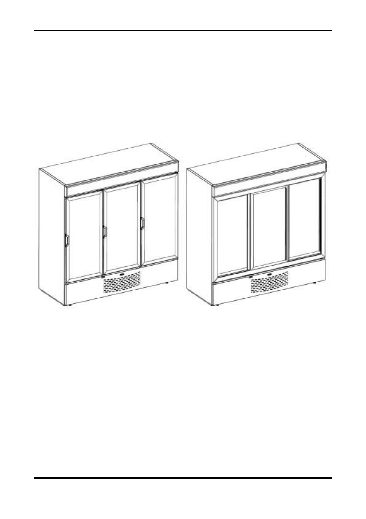
MIRACOOL™ GLASS DOOR MERCHANDISER
2000L
Sales Office:
P.O. Box 5932
Spartanburg, S.C. 29304-5932
Technical Service: 1-800-558-7627
Parts Order Fax: 1-800-262-9381
Manufacturer reserves the right to discontinue,or change at any time, specifications or designs without notice and without incurring obligations.
Printed in Mexico 10-06 79BC560010-01_C
Page 2
CONTENTS
Page
GENERAL.........................................................2
UNIT INSPECTION ...........................................2
INSTALLATION.............................................2-5
LOCATE UNIT..............................................2
LEVEL .........................................................4
INSTALL SHELVES .....................................5
CONDENSATE DISPOSAL..........................5
START-UP.....................................................6-7
PRELIMINARY CHECKS..............................6
INITIAL START-UP.......................................7
REFRIGERATION SYSTEM SERVICE........8-11
COMPONENTS............................................8
SERVICE AND TROUBLESHOOTING....8-11
MAINTENANCE.........................................12-13
LAMP REPLACEMENT..............................12
CONDENSATE REMOVAL.........................12
CONDENSER/EVAPORATOR...................12
CABINET EXTERIOR.................................12
INTERIOR SURFACE.................................12
GENERAL
These instructions cover the installation,
operation, and maint enance of Carrier Miracool™
series glass door mer c handiser units, size 2000L.
UNIT INSPECTION
Examine all packages for damage to packaging
material. Damage to external packaging may hav e
resulted in unit damage. Check packages for all
accessories and components, including legs,
casters, and shelves. File a claim immediately
with the shipping company if shipment is
damaged or incomplete.
INSTALLATION
LOCATE UNIT
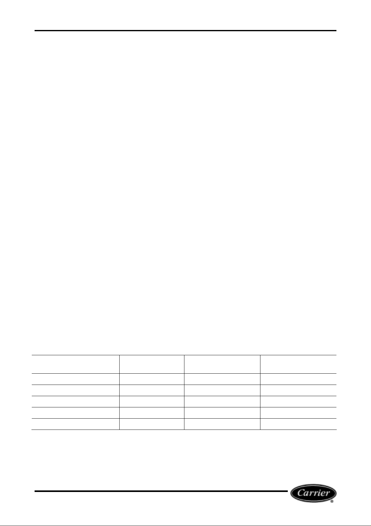
Refer to Figure 1 for unit components. Units are
designed for indoor placement only. Provide at
least 3 inches of space between uni t cabinet and
any adjacent wall or fixture.
Remove skid base by removing the retaining
screws (8 hex head bol t screws). Refer to Figure
2 to remove the front grille and gain access to skid
retaining screws. If optional casters will be used,
unit must be l ocated on flat, level surface. Refer to
Table 1 for a list of standard part s.
TABLE 1 – STANDARD PARTS
PART FACTORY
INSTALLED
Shelves X 15
Shelf Clips X 60
Instruction Manual - - 1
Leveling Feet X 4
Lamps X 4
Note: Parts shown are for standard units. Quantity of shelves and clips may vary based on factory-supplied options.
FIELD INSTALLED QUAN TITY
2
Page 3
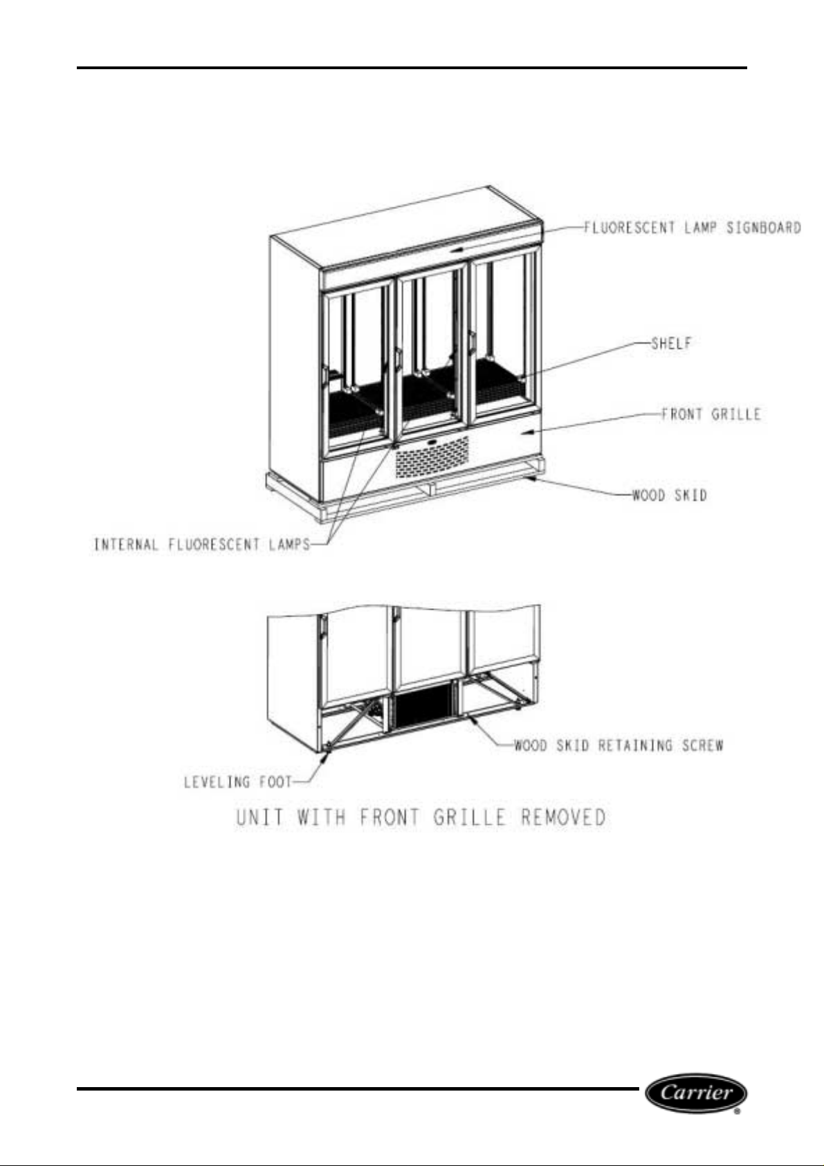
FIGURE 1 - MIRACOOL™ BOTTLE COOLER UNIT COMPONENTS (MC2000H S HOWN)
3
Page 4
LEVEL UNIT
To provide adequate condensate drainage and
proper door alignment and operation of unit, the
unit cabinet must be level. Leveling feet are
factory installed. Remove the front grille to gain
access to front and back feet.
TO GAIN ACCESS TO LEVELING
FEET
U
DANGER
Before servicing unit, disconnect electrical
service. Failure to disconnect electrical service
could result in electrical shock and cause
personal inj ur y or death.
1. After disconnect ing the unit from the power
supply, remove the grille retaining screw
located in the upper -most part of t he grille.
(See Figure 2)
2. Lift the grille up and away fr om the unit.
3. Unplug the power supply cord located at the
bottom of the cabinet. (See Figure 3)
FIGURE 3 – DISCONNECT SERVICE CORD
TO LEVEL UNIT
U
DANGER
Before servicing unit, disconnect electrical
service. Failure to disconnect electrical service
could result in electrical shock and cause
personal inj ur y or death.
Swing Doors- The door is equipped with gravity
assisted cams and will not function properly
without proper leveling of cabinet. Adjust feet
using adjustable wrench so that unit sits
approximately level to floor and doors close
properly. For best door operation, adjust leveling
feet so that cabinet has a
front to back. Optional casters are available to
replace leveling feet.
Slidin g Doors- The door will not function properl y
without proper leveling of cabinet. Adjust feet
using adjustable wrench so that unit sits
approximately level to floor and doors close
properly.
1/16-in. rake or sl ant from
FIGURE 2 – REMOVE FRONT GRILLE
NOTE: If casters are not used, local codes may
require cabinet to be sealed around the perimeter
of the cabinet base. Consult local sanitation c odes.
Use only sealant material approved for this use,
such as Dow Corning #732.
4
Page 5
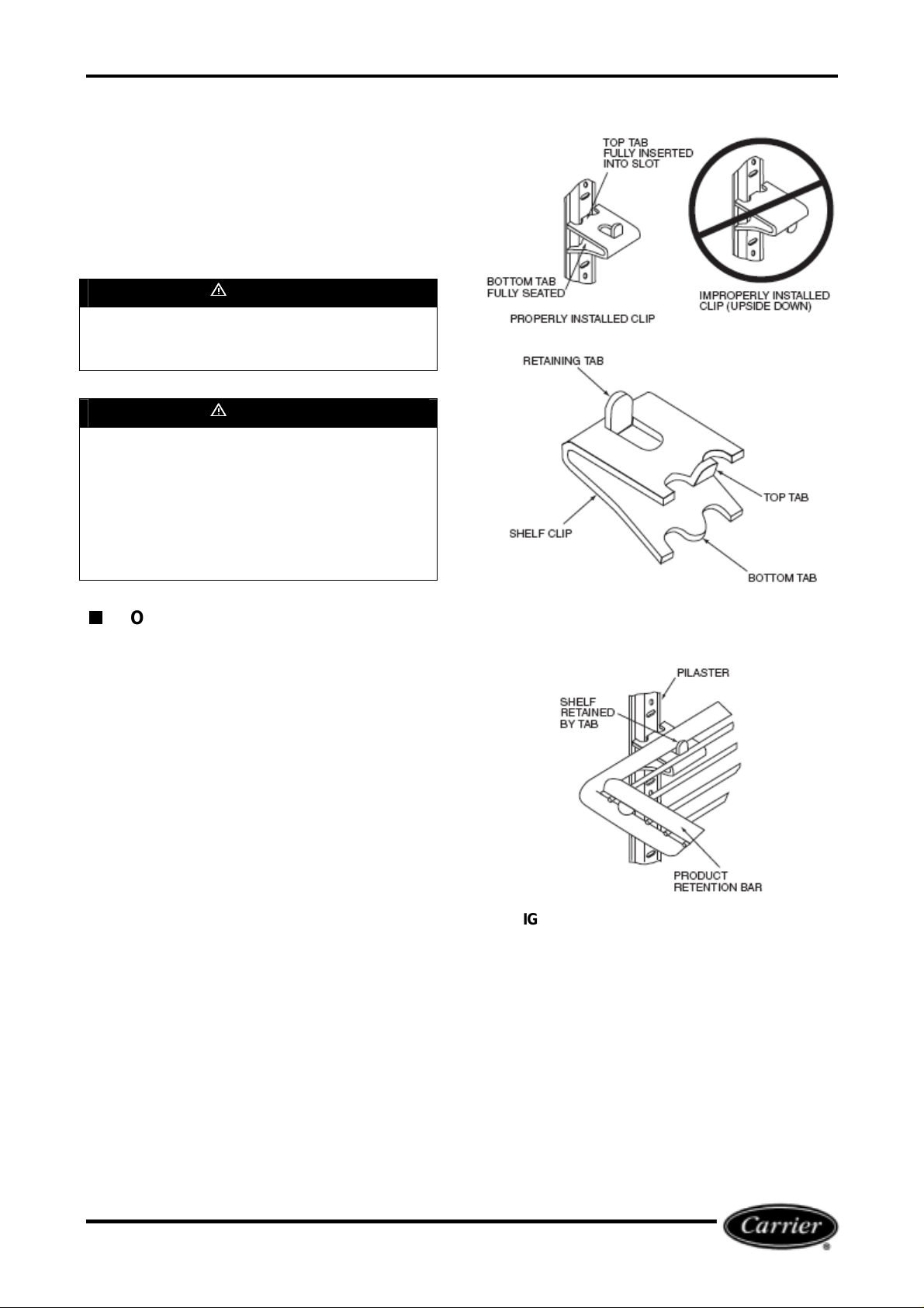
INSTALL SHELVES
Product shelves and a bag containing shelf
support clips are pac ked inside the unit. Refer t o
Table 1 to verify quantity of shelves and shelf
supporting cli ps. Bottom shelf m ust be placed on
interior floor and should be inserted into the two
retainer clips provided at the rear corners or the
unit floor.
U
WARNING
Improper shelf clip installation may cause shelf
and/or product to fall which could result in
personal inj ur y or damage t o the unit .
U
WARNING
Do not overload t he shelves. The unit is designed
to use all the shelves provided, installed in
equally spaced configuration. Failure to install
shelves correctl y could result in personal i njury or
damage to the unit. If fewer shelv es or a dif ferent
installation configuration is desired, contact the
manufacturer t o ensure that shelf overl oading will
no occur.
TO INSTALL SHELVES
1. Determine proper location for shelf clips.
Refer to the numbers on the pilaster to
ensure that all clips are properly located.
2. Insert top tab of the shelf clip into the
desired hole of the pilaster. The retaining
tab should be facing upward as shown in
Figure 4.
3. Rotate the clip downward and insert the
bottom tab into the appropriat e hole on the
pilaster. If necessary, squeeze the clip
slightly duri ng installation.
4. Install all remaining clips as described
above.
5. Instal l shelves onto clips so that the product
retention bar is facing upward. Be careful
not to dislodge clips during shelf installation.
6. Shelves must be placed so that the retaining
tab on the shelf captures the shelf as shown
in Figure 5.
7. Before loading the shelf, ensure that the
shelf is resting on each of 4 clips and that
the clip are install ed as shown in Figures 4
and 5.
FIGURE 4 – SHELF CLIP INSTALLATION
FIGURE 5 – PROPER INSTALLATION OF
SHELF ON CLIP
CONDENSATE DISPOSAL
The evaporat or drain pan i s loc ated i n the base of
the product. Airflow in compartment hastens
condensate evaporation so that external drain
plumbing is not r equir ed.
5
Page 6

START-UP
PRELIMINARY CHECKS
BI-PIN FLUORESCENT LAMP
INSTALLATION / VERIFICATION
Before applying power to the unit, verify that all
lamps have been properly installed and are fully
engaged in the lam p holders. There are 2 lamps
in the signboard and 2 insi de the cooler.
U
CAUTION
Improperl y install ed lam ps may cause dam age to
the lighting cir cuit. Carrier will not be responsible
for equipment of component falilures or other
damages or losses that arise as a result of
improper lamp installation.
To achieve proper lamp engagement, rotate the
lamp 90 degrees fr om its insertion posi tion until it
snaps or clicks into place.
On units without safety shields, visually verify
proper lamp installation by checking the
identification mark on the end of the bulb. If the
bulb has been properly install ed, the mark will be
centered between the “halv es” of the lamp holder.
Refer to Figure 6.
On units with safety shields, the identification
mark cannot be seen (See Figure 7). Verify
manually that the lamp has been rotated and
locked into place.
BI-PIN LAMP END
IDENTIFICATION
MARK
Properl y install ed lamp wit hout
shield. Verify identification
mark is posit i on ed as s h ow n.
Properly installed lamp
with shield. Requires
manual verification that
lamp has been rotated
and locked into place.
Improperly installed lamp
with shield. N ote that p ins
have not ac hieved full 90°
rotation.
FIGURE 7- CHECK INSTALLATION OF LAMP
WITH SHIELD.
ELECTRICAL SUPPLY AND
CONNECTIONS
Check to be sure that t he electrical servi ce to the
unit meets all local and national elect rical codes.
Unit electri cal data is shown in the unit data label,
located on the inside of the cabinet in the upper
lefthand cor ner.
Review this label before initi ating elec trical servi ce.
Voltage range of power supply to unit should be
105 to 125 volts. Refer to T abl e 2 for unit data.
NOTE: Other motors or heavy appli ances should
not be used on the same circuit with the cooler.
See Figure 1 for loc ation of service cord.
U
DANGER
Before servicing unit, disconnect electrical
service. Failure to disconnect electrical service
could result in electrical shock and cause
personal inj ur y or death.
U
CAUTION
If an extension cord is necessary, use only three
wire grounding type. The use of ungrounded
cords or overloaded circuit voids compressor
warranty.
FIGURE 6 – CHECK INSTALLATION OF LAMP
WITHOUT SAFETY SHIELD.
6
Page 7

TABLE 2 – UNIT DATA
UNIT MC2000H /
MC2000S
Voltage (V)
Nominal 115
Range 105-125
Frequency (Hz) 60
Total Amps 11.3
Refrigerant Type R-134A
Charge Amount (oz) 19.4
Design Pressure (psig)
High Side 220
Low Side 88
INITIAL START-UP
POWER SUPPLY
Connect unit to power supply. Check to verify that
the compressor, lam p and fans are running.
Important: Low li ne v oltage is often the cause of
service complaints. Check to see that the line
voltage is within specified range with the unit
running.
TEMPERATURE
CONTROL KNOB
FIGURE 8 – TEMPERATURE CONTROL KNOB
TEMPERATURE CONTROL
The temperatur e control knob is locat ed inside t he
cabinet in the m otors panel. See Figure 8. Unit is
factory set at the number 4 position (normal),
which will maintain the product at approximately
38F. For colder temperature, turn the black
adjustment knob to a higher setting. Adjust
temperature control in small increments, one
position at a tim e.
U
CAUTION
Allow 24 hours between temperature control
adjustments. Excessive tampering with
temperature control could lead to service
difficulties.
NOTE: For operation above 3,000-ft altitude,
thermostat should be adjusted by a qualified
service technician.
7
Page 8

REFRIGERATION
SYSTEM SERVICE
SERVICE AND
TROUBLESHOOTING
COMPONENTS
The Carrier Miracool™ refrigeration system
consists of a hermetically sealed com pressor and
finned evaporat or and condenser coils.
CONDENSER
The condenser has wide finned spaces, which
allow more air passage with less dirt or dust
accumulation. The condenser still requires
periodic cleaning for maximum efficiency.
CONDENSER FAN MOT OR
The condenser fan motor assembly is mounted
between the condenser and the compressor. Air is
drawn through the condenser, over the body of
the compressor and out the rear of the unit
compartment . The m otor i s wired t o cycl e wit h the
compressor but will continue to operate should the
compressor cut out on the overl oad. (The motor i s
permanently lubricated; therefore, oiling is not
required.)
DRIER
The drier is installed in the system just before the
capillary tube. The drier traps minute particles of
foreign material and absorbs any moisture in the
system.
LIQUID CONTROL AND HEAT
EXCHANGER
Liquid ref rigerant control to the evaporator of the
system is accompli shed by the use of a capillary
tube. This capill ary tube i s soldered to the sucti on
line to form a heat exchanger, whic h subcools the
liquid ref rigerant to m aintain high eff iciency within
the system.
CONDENSING UNIT SERVICING
U
DANGER
Before servicing unit, disconnect electrical
service. Failure to disconnect electrical service
could result in electrical shock and cause
personal inj ur y or death.
1. After disconnect ing the unit from the power
supply, remove the grille retaining screw
located in the upper -most part of t he grille.
(See Figure 2)
2. Lift the grille up and away fr om the unit.
3. Unplug the power supply cord located at the
bottom of the cabinet. (See Figure 3)
4. Remove the 2 hex-head screws that hold
the condensing unit base to the cabinet
main rails. (See figure 9)
5. Push the condensing unit base to gain
access to the refrigeration system
components.
U
DANGER
Before servicing unit, disconnect electrical
service. Failure to disconnect electrical service
could result in electrical shock and cause
personal inj ur y or death.
FIGURE 9 – RELEASE COND. UNIT BASE
8
Page 9

EVAPORATOR COMPARTMENT
SERVICING
U
DANGER
Before servicing unit, disconnect electrical
service. Failure to disconnect electrical service
could result in electrical shock and cause
personal inj ur y or death.
1. After disconnect ing the unit from the power
supply, remove the grille retaining screw
located in the upper -most part of t he grille.
(See Figure 2)
2. Lift the grille up and away fr om the unit.
3. Unplug the power supply cord located at the
bottom of the cabinet. (See Figure 3)
4. Remove the 4 philips screws that hold the
evaporator cover. (See Figure 10)
5. Hold the cover until it is completely loose
and hanged by the supporting pins. (See
Figure 11).
U
DANGER
Before servicing unit, disconnect electrical
service. Failure to disconnect electrical service
could result in electrical shock and cause
personal inj ur y or death.
EVACUATION
Moisture in a refrigeration system may affect
performance.
When large amounts of moisture are present,
system freeze ups will occur. Even in minute
amounts, moisture will combine with refrigerants
to form an acid.
The corrosive action of this acid forms sludge,
which will plug the lines and drier.
Since most fi eld type vacuum pumps cannot pull a
low enough vacuum to remove all moisture from
the system, it is recommended that the system be
triple evacuated, breaking each time with dry
refrigerant nitrogen. Use care to purge air from the
charging hose when breaki ng the vacuum.
CHARGING REFRIGERATION
SYSTEM
Refer to Table 2 for refrigerant type and amount of
charge. Since capillary tube systems have small
critic al refrigerant charges, it is recommended t hat
a field charge eit her be weighed in or transfer red
from a portabl e charging cylinder . After maximum
vacuum has been obtained as detailed above,
attach chargi ng cyli nder to the system li ne making
sure to purge air from hose with refrigerant. With
the unit running, allow refrigerant to run slowly into
the system until the desired charge is reached.
When using refriger ant blends it is recommended
to charge into the high side of the system with the
initial c harge and then add any remaining charge
into the suction side; however, car e m ust be taken
to meter the remaining amount into the low side
so that excess liquid does not enter the
compressor.
FIGURE 10 – RELEASE EVAPORATOR COVER
FIGURE 11 – EVAPORATOR COVER SUPPORT
TROUBLESHOOTING
Refer to Table 3 and Figure 12.
9
Page 10

TABLE 3 – REFRIGERATION SYSTEM SERVICE AND ANALYSIS CHART
REFRIGERATION SYSTEM
MALFUNCTION POSSIBLE CAUSE SOLUTION
1. Line cord n ot plugged in.
Compressor will not start
- no hum -
Compressor will not start
- hums but tri ps on ov erload
protector.
Compressor starts but does not
switch off of start winding.
Compressor starts and
runs, but short cycles on
overload protector.
Unit runs OK, but short
cycles.
Unit oper at es l ong or
continuously.
Start capacitor open, shorted or
blown.
Run capacitor open, shorted
or blown
Relay defective or burned out
Space temperature too high
Cooler freezing beverage 1. Temperature control 1. Reset control.
Unit noisy
2. Fuse rem ov ed or bl ow n .
3. Overload protector tripped.
4. Temp control stuck in open position.
5. Wiring improper or loose.
1. Low voltage to unit. 1. Determ in e reason and corr ec t.
2. Relay failing to close
3. Starting capacitor defective. 3. Determine reason and replace.
4. Improperly wired . 4. Ch eck wiring ag ai ns t di agram.
1. Low voltage to unit. 1. Determ in e reason and corr ec t.
2. Relay failing to open.
3. Run capacitor defective. 3. Determine reason and replace.
4. Compr essor mountin g w in di ng is op en or
shorted.
1. Additional current passing through overload
protector.
2. Low voltage to unit. 2. Determ in e reason and corr ec t.
3. Overload protector defective. 3. Check current, replace protector.
4. Run capacitor defective. 4. Determine reason and replace.
5. Excessive discharge pressure.
6. Compressor too hot - return gas hot.
1. Overload protector. 1. Check wiring diagram for correct wiring.
2. Cold control. 2. Differential set too close.
3. Overcharge. 3. Reduce refrigerant charge.
4. Air in system. 4. Recover and recharge.
5. Undercharge. 5. Fix leak and recharge with refrigerant.
1. Dirty condenser. 1. Clean condenser.
2. Shortage of refrigerant. 2. Fix leak, add charge, correct charge.
3. Temperature control contacts stuck or frozen. 3. Replace temperature control.
4. Evaporator coil iced. 4. Defrost.
5. Restriction in refrigeration system. 5. Determine location and remove.
1. Relay contacts not opening properly. 1. Replace relay.
2. Low voltage to unit. 2. Determ in e reason and corr ec t.
3. Improper relay. 3. Replace.
1. Improper capacitor. 1. Determine correct size and replace.
2. Excessively high line voltage (110% of rated
max).
1. Incorrect relay. 1. Check and replace.
2. Line volt ag e too high or too low . 2. Det er m in e reason and rep l ac e.
3. Relay being influenced by loose vibrating
mounting.
1. Control setting too high. 1. Reset control.
2. Overcharged with refrigerant.
3. Inadequate air circulation. 3. Improve air movement.
1. Loose p arts or m ou nti ngs . 1. Find and tig hten.
2. Tubing rattles. 2. Reform to be free of contact.
3. Bent fan blade causing vibration. 3. Replace blade.
4. Fan motor bearings worn. 4. Replace mot or.
1. Plug in the cord.
2. Replace fuse.
3. Refer to electrical section.
4. Repair or replace temp control.
5. Check wiring agai ns t diagram.
2. Determine reason and correct, replace if
necessary.
2. Determine reason and correct, replace if
necessary.
4. Determine cause, correct, and replace
compressor.
1. Check wiring diagram. Check for added fan
motors, pu m ps , etc . c onn ec ted to wrong side of
protector.
5. Check ventilation, restrictions in cooling medium,
restrictions in refrigeration system.
6. Check refrigerant charge (fix leak if necessary).
Check airflow across condenser.
2. Determine reason and correct.
3. Remount rigidly.
2. Recover r ef rig erant and rech ar g e w it h proper
charge sp ec if i ed on data plate.
10
Page 11

FIGURE 12 – WIRING DIAGRAM
11
Page 12

MAINTENANCE
LAMP REPLACEMENT
U
DANGER
Before servicing unit, disconnect electrical
service. Failure to disconnect electrical service
could result in electrical shock and cause
personal inj ur y or death.
Remove lamp by rotating lamp 90 degrees to
align lamp pins with hol der slots. Refer to Bi-Pin
Fluorescent Lamp Installation / Verification section
on page 5.
CONDENSATE REMOVAL
The evaporat or drain pan i s loc ated i n the base of
the condensing unit. The evaporator pan should
be cleaned periodically to prevent odors and
maintain evapor ating efficiency. T he pan contains
wicks to assist evaporation and should be
replaced periodically.
CONDENSER
U
DANGER
Before servicing unit, disconnect electrical
service. Failure to disconnect electrical service
could result in electrical shock and cause
personal inj ur y or death.
CABINET EXTERIOR
Cabinets should be cl eaned with a solution of mild
soap and water or mild household c leaner. Do not
use caustic soap or abrasive cleaners, since
these might damage the cabinet finish. If stainless
steel surfac e bec om es di scolored, scrub by
rubbing only i n dir ection of the finish grain. Do not
use steel wool or rusting may occur. Refer to
Table 4.
INTERIOR SURFACE
The inside of the cabi net is coated with baked-on
epoxy. To clean, use a mil d soap and water
solution or mil d househol d c leaner.
EVAPORATOR HOUSING
U
DANGER
Before servicing unit, disconnect electrical
service. Failure to disconnect electrical service
could result in electrical shock and cause
personal inj ur y or death.
Evaporator and other enclosed parts normally will
not require cl eaning.
In case there’s some spill age refer to Evaporat or
Compartment Servici ng secti on on page 9 to open
the compartm ent.
For effici ent operation, it is recommended t hat the
condenser coil and f ans be cleaned ever y 3 to 6
months. Remove front grille for access. Refer to
Condenser Unit Servicing section on page 8.
Vacuum clean front surface of coil thoroughly or
direct forced air through condenser fi ns. Failure to
clean condenser can cause compressor
malfuncti on and wil l v oid warrant y .
Side walls and cover should be cleaned as
described in I nterior Surface section in this page.
12
Page 13

TABLE 4 –METHODS FOR CLEANING STAINLESS STEEL
TASK CLE A NING AGENT * METHOD OF A P P L I CATI ON EFFECT ON FINISH
Routine Cleaning Soap, am m on i a or det ergent
Stubborn Spots and Stain s,
Caked-on Splatter, and other
Light Discolor ations
Heat Ting or Heavy
Discoloration
Caked-on Foods and Grease ,
Fatty Acids Milkstone (where
swabbing or rubbing is not
practical)
Hard Water Spots and Scale Vinegar. Swab or wipe with cloth. Rinse
and water
Revere Ware, Goddard’s,
Twinkle or Cameo stainless
steel cleaner or Soft Scrub
cleaner.
Household cleansers, such as
Old Dutch, Bon Ami, Ajax,
Comet.
Revere Ware, Goddard’s,
Twinkle or Cameo stainless
steel cleaner.
Easy-Off oven cleaner. Apply generous coating. Allow
Sponge with cloth, then rinse
with clear w at er and wi p e dry.
Apply with a damp sponge or
cloth. Rub with a damp cloth.
Rub with a dam p cl oth. May
contain chlorine bleachers.
Rinse thoroughly aft er use.
Apply with damp sponge or
cloth.
to stand f or 10 t o 15 min ut es .
Rinse. Repeated application
may be necessary.
with water an d dry.
*Use of brand names is intended only to indicate a type of
clean er and d oes n ot cons ti tute an end ors em ent; nor does th e
omission of any brand name cleaner imply its inadequacy.
Many pr oducts n amed are r egion al in distri bution and can be
found in local su permarket s, department and hardw are stores.
All products should be used in strict accordance with
instruct i ons on package.
NOTES:
1. Use the mildest cleaning procedur e that will do the job
effici ent l y an d effectivel y.
2. Always rub in the direction of the polish lines for
maxim um eff ectiveness and to avoid marri ng th e surface.
3. Use only a soft cl ot h, sponge, fiberous brushes, plastic or
stainless steel pads for cleaning and scouring.
4. Rinse thoroughly with fresh water after every cleaning
operation.
5. Always wip e dry t o av oi d w at er m ar ks.
6. Never use common steel wood pads; these will cause
rust.
Satisfactory for use on all
finishes.
Satisfactory for use on all
finishes if rubbing is light. Use
in directi on of polish lines .
Use in direction of polish lines.
May scratch or dull highly
polished finishes.
Use in direction of polish lines.
May scratch or dull highly
polished finishes.
Excellent removal. Satisfactory
for use on all fin is hes.
Satisfactory for use on all
finishes.
13
Page 14

Copyright 2006 Carrier Corporation
Manufacturer reserves the right to discontinue, or change at any time, specifications or designs without notice and without incurring obligations.
Printed in Mexico 10-06 79BC560010-01_C
 Loading...