

Carrier MDB121NO170F, MDB121TO170F, BDB121NO170F, BDB121TO170F, MDB123TO170F Use And Maintenance
...Page 1

USE AND MAINTENANCE
BEDIENUNGSANLEITUNG
INSTRUCTIONS D’USAGE ET ENTRETIEN
USO E MANUTENZIONE
DB-O
DB-O
Page 2

2
a = Condensing Unit • Verflüssigungssatz • Unité de Condensation • Unità Condensante
b = Cooler • Verdampfer • Evaporateur • Unità Evaporante
Pipe connections
Rohranschlüsse
Raccordements
Raccordi
Code Cooling capacity Nominal horsepower Voltage
Running Nominal absor. Max. Absor. Refrigerant Air Flow Air throw Net Weight Suction line Liquid line
Code Kälteleistung Nennleistung Spannung
Nennaufnahme bei Betrieb
Nennaufnahme max.
Kältemittel Luftmenge Luftwurf Poids Net Saugleitung Flüssigkeit
Code Puissance frig Puissance nominale Tension
Absorp. nomin. en marche Absorp. max
Réfrigérant Débit d’air Projection d’air Nettogewicht Aspiration Liquide
Codice Potenza Frigorifera Potenza nominale Tensione
Assorb. nom. in marcia Assorb. mass. Refrigerante Portata d’aria Freccia d’aria Peso Netto Aspirazione Liquido
Ta/Tc (°C) Watt HP Kw Volt/Ph/Hz Kw A A m
3
/h m Kg
ø mm ø mm
ab
MDB121NO170F
+30 / 0 1096 1/2 0,4 230/1~/50 0,6 3,8 5,4 R404A 600 4 39 13 12 6
MDB121TO170F
+30 / 0 1162 5/8 0,5 230/1~/50 0,7 4,3 7,9 R404A 600 4 43 13 12 6
BDB121NO170F
+30 / -20 761 1 0,7 230/1~/50 0,8 4,8 7,6 R404A 600 4 43 13 12 6
BDB121TO170F
+30 / -20 965 1,2 0,9 230/1~/50 0,8 5,0 7,5 R404A 600 4 46 13 12 6
MDB123TO170F
+30 / 0 1332 3/4 0,6 230/1~/50 0,8 5,0 8,4 R404A 600 4 43 13 12 6
BDB123TO170F
+30 / -20 1096 1,7 1,3 230/1~/50 0,9 5,5 11,3 R404A 600 4 50 13 12 6
MDB221TO170F
+30 / 0 2243 1,2 0,9 400/3N~/50 1,5 4,3 5,9 R404A 1200 4 61 19 16 10
BDB221NO170F
+30 / -20 1507 1,7 1,3 230/1~/50 1 6,9 11,9 R404A 1200 4 61 19 16 10
BDB221TO170F
+30 / -20 1773 2 1,5 400/3N~/50 2,2 5,7 11,9 R404A 1200 4 69 19 16 10
MDB135NO170F
+30 / 0 3516 1,5 1,1 400/3N~/50 1,8 5,3 7,0 R404A 1800 9 62 28 16 10
MDB135TO170F
+30 / 0 4019 2 1,5 400/3N~/50 2,3 6,2 7,8 R404A 1800 9 70 28 16 10
BDB135NO170F
+30 / -20 2295 2 1,5 400/3N~/50 2,4 6,3 12,5 R404A 1800 9 72 28 16 10
BDB135TO170F
+30 / -20 2613 3 2,2 400/3N~/50 1,9 5,5 7,5 R404A 1800 9 78 28 16 10
- Maximum Outside temperature - Maximale Umgebungstemperatur - Temperature éxtérieure maximaIe- Limiti temperatura esterna : 45°C
DADATTAASHEET • DA
SHEET • DA
TENBLA
TENBLA
TT • FICHE TECHNIQUE • SCHEDA
TT • FICHE TECHNIQUE • SCHEDA
TECNICA
TECNICA
Page 3

3
SERVICE SHEET - SERVICEBLATT - FICHE DE SERVICE - FOGLIO SERVIZIO
DATE - DATUM OPERATION -MASSNAHME SERVICE FIRM - SERVICEFIRMA
SIGNATURE- UNTERSCHRIFT
DATE - DATA OPERATION - OPERAZIONE ETS DE SERVICE - DITTA ASSISTENZA SIGNATURE - FIRMA
Page 4

T
hank you for choosing our refrigerating unit. This model is equipped with a highly evolved electronic control panel that dispenses with a series
of conventional components such as timers, thermostats and thermometers while offering the facility for straightforward personalisation of the
control program to suit your needs. The panel also provides a self-diagnostic function showing the nature of any functional anomalies so that
they can be solved fast. This operation and programming manual has been published to assist you, please read it carefully.
1) OPERATION
The distinguishing feature of this unit is that it is formed of two separate parts: the condensing unit with remote electronic control panel, for instal-
lation outside the coldroom , and the evaporator for installation inside the room. This design solution eliminates problems related to space
restrictions outside the cell. The two units can be installed at a distance from each other. The air is drawn through the evaporator by means of
the motor driven fan and exhausted through the grids on the sides. In the evaporator, the air drawn in by the motor driven fan units is cooled
by the heat exchanger and expelled from the front of the unit. The temperature is monitored by room sensor. Once the set-point is reached the
refrigeration plant is stopped. Defrosting is automatic by means of electrical heaters in the evaporator; this cycle terminates in correspondence
with the "defrost end" temperature set on the control unit and detected by a sensor. The defrost water is collected in a tray located beneath
the evaporator from where it is drained to outside the rooml.
2) INSTALLATION
For correct installation, proceed thus:
1) Position the condenser unit on floor level outside the coldroom.
2) Secure the evaporator unit to the coldroom ceiling (pict. 1) as follows:
2A) Open the fan holder bottom ‘A’ by
loosing screws ‘B’ (pict. 2-3).
2B) Drill the fixing holes on the
coldroom ceiling observing the
recommended distance from the
wall (pict. 4).
2C) Secure the evaporator using the
supplied components (pict. 5):
1 - Threaded bar
2 - Washer
3 - Nut
2D) Hook up the evaporator to the electrical supply utilising the terminal board located inside
the junction box. Close the junction box and clamp the cable so that it is clear of the fan
blades.
2E) Re-close the air-cooler cover and then make the refrigeration connections (pict. 6).
REMOTE CONTROL PANEL INSTALLATION
Unscrew the lateral fixings to remove the remote control panel cover plate (pict. 7).
Fix the base plate in the desired position using the pre-drilled
holes and making sure it is level (pict. 8).
Replace the cover plate by performing the operation indicated at
pict. 7 in reverse.
Adjust the cable connection between the control panel and the
unit, making sure it does not interfere with existing cable
connections.
To assure optimal operation of the refrigerating unit:
A) Restrict the number of times the coldroom is opened.
B) Make sure that the unit has an efficient air intake and expels a generous amount of turbulent air.
C) Position the unit on horizontal planes..
D) Avoid to place the condensing unit in closed ambient or not ventilated.
4
pict. 3pict. 2
pict. 4 pict. 5
pict. 6
Condensing unit
Evaporator
pict. 1
pict. 7
pict. 8
E
N
G
L
I
S
H
100-150
B
A
3
1
2
2
1
Page 5

3) ELECTRICAL HOOK-UP
To make the correct electrical connections:
1) Make sure the line voltage corresponds to the voltage indicated on the dataplate of the unit (± 10%).
2) To reach the electronic panel it is necessary to remove the front cover (C) of the condensing unit (pict.1). For this operation remove the fixing
screws and position the selector (A) on 0.
3) Unscrew the screws (B) indicated in pict. 2 and remove the cover from the electronic panel.
LINE CABLE FOR SINGLE PHASE UNITS (230 V)
- Remove the plug (D) (pict.2) and insert a cable gland
PG16. Insert the power cable (of the section indicated in
the table of fuses) in the cable gland and connect:
1) the phase wire to the terminal1 (L1) of the isolator Q1
2) the neutral wire to the terminal 5 (N)
3) the protection wire (earth) to the terminal PE
- Tighten the cable gland.
LINE CABLE FOR THREE-PHASE UNITS (400 V)
- Remove the plug (D) (pict.2) and insert a cable gland PG 16. Insert the power cable (of the section indicated in the table of fuses) in the cable
gland and connect:
1) the phase wires to the terminals 1 (L1) - 3 (L2) - 5 (L3)
2) the neutral wire to the terminal 7 (N)
3) the protection wire (earth) to the terminal PE
- Tighten the cable gland.
CONNECTION CABLE DOOR HEATER
- Remove the plug (E) (pict. 2) and insert a cable gland PG 11. Insert the cable of the door heater and connect:
1) the phase wire to the terminal 40 of the electrionic control panel (G)
2) the neutral wire to the terminal N of the electronic control panel (G)
3) the protection wire (earth) to the earth terminal (60) GND
- Tighten the cable gland.
Remeber that the voltage in output to the card is 230 V 1Amp. MAX. It is necessary to protect the door heater with a fuse (by costumer).
MICRO-DOOR CONNECTION
- Remove the plug (F) (pict.2) and insert a cable gland PG 11.
- Insert the cable deriving from the micro-door and connect the bands to the terminals 19 and 20 of the electronic control panel (G) after removing connection bridge .
The installation has to follow the sequence:
closed door - micro-door contact closed
opened door - micro-door contact opened
- Tighten the cable gland.
WARNING: do not give voltage to the micro-door as it is fed with voltage deriving from the electronic control panel (low voltage).
When the operations for the electronic panel connection have finished close with the screws B (pict.2). Close the front cover (C) of the conden-
sing unit (pict. 1).
4) PROCEDURES BEFORE STARTING
Before switching on the unit check that:
The fixing screws are properly tightened
The electrical and refrigeration connections have been made correctly
If the unit has been opened check that:
No tools have been inadvertently left inside the enclosure
The enclosure has been assembled correctly
There are no gas leaks
The panels have been fitted correctly.
5) PLACING INTO SERVICE
Perform all the above mentioned connections and then the unit can be started.
A period of pre-heating is required; this is achieved by powering up the unit without switching on the control unit for at least 2 hours (3 hours in
cold climates). This procedure must be repeated whenever the plant is idle for periods in excess of 12 hours.
5
pict. 1
pict. 2
E
N
G
L
I
S
H
G
C
B
A
F
E
D
Q1
PE
Page 6

6) DESCRIPTION OF ELECTRONIC PANEL
1) Compressor LED (GREEN):
LIT: the compressor is running.The unit is cooling.
FLASHING: the compressor is a delayed start mode.
OFF: the compressor is OFF. The required room temperature has been reached .
2) Evaporator fan LED (GREEN):
LIT: Evaporator fan is running.
FLASHING: the evaporator fan is in a delayed start mode.
OFF: Evaporator fan is off.Unit in Defrost mode.
3) Defrost LED (YELLOW):
LIT: automatic or manual defrost in progress.
4)Alarm LED (RED):
LIT: Alarm mode: malfunctioning of a sensor, or intervention of pressure-stat or room temperature
outside preset limits.
OFF: Unit working normally.
5) DISPLAY: When the machine is not in operation, the label “OFF” and the cell temperature are inter
mittently displayed one after the other on the digital display.When the machine is in operation,
during the normal working cycle, the display indicates the cell temperature. Parameters being set
will be displayed during programming. A "Fault Code" will be displayed during alarm mode.
6) “SET” KEY. Permits entry of room temperature requirements.
7) “DOWN” KEY. Key to decrease data values.
8) “MAN.DEFR./UP” KEY. Key to increase data values. Press for 8 seconds at least to initiate manual defrost as well.
9) Key “T.A.A.” Key to mute audible alarm.
This alarm is not fitted as standard to the unit but can be added by the client. To connect use the free terminals 1 & 2 (volt free) on the internal
electronic panel. Terminal 2 should have a live feed brought to it.
10) “ON/OFF” KEY.Main switch.
11) “LAMP” KEY.Push to turn room lamp ON/OFF.A red LED lights when lamp is ON.
7) PROGRAMMING
With the unit in normal operating mode,the only active keys are "ON/OFF" (10) and "LAMP"(11). The latter is always operative except when in
programming mode.
Cell temperature programming:
- Press key (10) to turn ON unit.The actual room temperature will be shown on the display (5).In this condition the unit is ready for programming.It is necessary therefore to set the required room temperature bearing in mind the limits of the range which the unit is able to operate.
- Press the SET (6) key (the yellow LED will light).The last set temperature will be displayed on the display screen (5) which showes the set
value.
Press the set key (6): the yellow led will light for one second and the display (5) will start flashing a few seconds later, indicating the set tempera-
ture. If you wish to change the setting, use the following keys:
(8) to raise set temperature
(7) to lower set temperature
Once the required setting is displayed, press the set key (6) to confirm. The unit is now fully operational and no other programming is requi-
red. The refrigerating cycle is fully automatic according to factory-set parameters, that can eventually be modified by authorised personnel
only.
8) ALARMS
When a fault is detected,the red Led in key (4) will be lit and a fault code displayed on the screen (5).This code enables a speedy identification
of the problem and should be reported when making the service call.(The audible alarm will also sound if fitted).
HIGH TEMPERATURE ALARM
The label (HI) and the cell temperature are intermittently displayed one after the other.
Alarm relay activated
Causes: - The door has been opened too frequently - The product load in the cell exceeds cell capacity - The temperature of the products
stored in the cell is too high - Refrigeration system malfunction
LOW TEMPERATURE ALARM
The label (LO) and the cell temperature are intermittently displayed one after the other.
Alarm relay activated
Causes: -Electronic control unit malfunction. Solution: -Call technical assistance service
AMBIENT TEMPERATURE SENSOR ALARM
The label (EO) appears on the digital display.
Alarm relay is active
Causes: -The sensor is not connected. Solution: -Replace sensor
EVAPORATOR SENSOR ALARM
The label (E1) and the cell temperature are intermittently displayed one after the other.
6
Minimum Temp. Maximum Temp
M RANGE (Medium temperature) - 5 °C +10 °C
B RANGE (Low temperature) - 25 °C - 15 °C
E
N
G
L
I
S
H
4
5910
3
2
1
67811
Page 7

Causes: -The sensor is not connected. Solution: -Replace sensor
HIGH PRESSURE ALARM
The label (HH) and the cell temperature are intermittently displayed one after the other; led (4) lights up each time the high pressure switch is tripped.
If the high pressure switch is tripped more than 10 times in a one-hour period, the label (PP) and the cell temperature will appear intermittently
one after the other on display (5), while the alarm relay will be activated together with led (4). Room light switch, evaporator & condenser fan
OFF. To reset the alarm, disconnect the refrigeration unit, wait for a few seconds, then restore connection.
Causes: -Ensure that the condenser fan is working properly -Ensure that the condenser is clean.
9) EMERGENCY
In case of fault or malfunctioning of the electronic control panel,if a short-term replacing is not possible, an
“EMERGENCY SYSTEM” can be used to keep the unit running until a new control panel may be installed.
The “EMERGENCY SYSTEM” consists of a terminal board sited on the control panel, fitted with 4 terminals , as
shown in picture 1.
Proceed as follows to use the system:
1)
Switch the electronic control panel off by pressing the key ON/OFF (10).
N.B.: The electronic control panel should remain in this condition during the whole emergency period.
2) Switch the unit off.
3) Connect a thermostat (6 inductive Amps.) to the terminals E1 and E2 (Pict. 2).
4) Bridge terminals E2 and E3 as well as terminals E3 and E4. (Pict. 2).
5) A wire comes out from nr. 30 on the card; it is welded in the card an connented to terminal 4. Disconnect it and
let it free.
6) Enter the thermostat bulb inside room.
7) Adjust the 'stat at the required temperature and switch the unit on.
8) When the set temperature is reached, compressor, evaporator and condenser fans will stop.
9) During emergency period, defrost-cycle is cut-out;it is therefore advisable to reduce door openings to a minimum.
10) When installing a new control panel, remove all connections stated in items 3 and 4,before switching the unit on.
10) ROUTINE MAINTENANCE
- All installation, maintenance or repair interventions must be carried out exclusively by authorised personnel.
- In order to assure reliable operation of the unit the condenser must be cleaned periodically (the frequency of cleaning depends mainly on the
surroundings in which the unit is installed). This operation must be carried out with the unit stopped; we recommend using a jet of compressed
air blowing from the inside toward the outside; if this is not practical, use a brush with long bristles and brush the outside of the condenser unit
- Refrigerants (HFC) must not be disposed of in the environment.
- The plant cannot be charged with refrigerants other than the type specified on the dataplate unless this action has been previously explicitly
authorised by the manufacturer.
IMPORTANT NOTE: the units are equipped with a pressure switch monitoring condensation pressure so the condenser fan may stop during
operation of the compressor.
7
Pict. 1
Pict. 2
E
N
G
L
I
S
H
E4 E3 E2 E1
E4 E3 E2 E1
T
FTE
Page 8

PPOOWWEERR CCUURRRREENNTT FFUUSSEE CC AA RRDD FFUUSSEE
LLIINNEE CCAABBLLEESS SSEECCTTIIOONN
LLEEIITTUUNNGGSSSSII CCHHEERRUUNNGG KKAARR TT EENNSSIICCHHEE
KKAABBEELLSSLLIINNIIEESSCCHHNNIITTTT
LL II SS TT OOFF FFUUSSEESS -TT AA FF EELL DDEERR SSCC HH MMEELL ZZ SS II CCHH EE RR UU NN GG EENN -TTAABBLL EEAAUU DDEERR FFUUSSIIBB LL EE SS -TT AABBEE LL LL AA FFUUSSIIBB IILL II
LL II SS TT OOFF FFUUSSEESS -TT AA FF EELL DDEERR SSCC HH MMEELL ZZ SS II CCHH EE RR UU NN GG EENN -TTAABBLL EEAAUU DDEERR FFUUSSIIBB LL EE SS -TT AABBEE LL LL AA FFUUSSIIBB IILL II
FFUUSSII BBLL EE DD EE LLIIGGNNEE CCAARR TT EE FFUUSSII BBLL EE
SSEECCTTIIOONN CCAABBLLEESS LLIIGGNNEE
FFUUSSII BBIILLEE DD II LLIINNEEAA FFUUSSIIBBIILLEE SSCCHH EEDDAA
CCAAVVOO LLIINNEEAA CCOONNSS..
DDIIAAZZEEDD
MM OO DDEELL RRaannggee VVee rrssiioonn VVoollttaaggee
MM OO DDEELL LL RReeiihhee AAuu ssffuueehh rruunngg SSppaannnnuunngg
MM OO DDEELL EE GGaammmmee VVeerrssiioonn GGaass VVoollttaaggee AAmmppeerr ee nnºº .. AAmmppeerree mmmm
22
MM OO DDEE LL LL OO GGaammmmaa VVeerrssiioonnee TTeennssiioo nnee
20
POWER CURRENT FUSE: We advise the use of such a fuse (circuit breaker) fitted in the line ; otherwise a suitable fused isolator can be used.
LEISTUNGSSICHERUNG: Man raet die Verwendung solcher Schmelzsicherung auf der Linie eingebaut ; anderfalls kann man einen
Thermomagnetschalter verwenden.
FUSIBLE DE LIGNE: Nous conseillons d' installer cet fusible en amont de l'installation ; alternativement on peut utiliser un adéquat interrupteur
magnétothermique.
FUSIBILE DI LINEA: Si intende un fusibile posto a monte dell'impianto , che vivamente consigliamo;in alternativa é possibile l'utilizzo di un
adeguato interruttore magnetotermico.
M
MDB121NO170F
R404A 230/1~/50 16 1 6,3 3x1,5
DB121
MDB121TO170F
R404A 230/1~/50 20 1 6,3 3x1,5
B
BDB121NO170F
R404A 230/1~/50 25 1 6,3 3x1,5
BDB121TO170F
R404A 230/1~/50 25 1 6,3 3x1,5
M
MDB123TO170F
R404A 230/1~/50 25 1 6,3 3x1,5
DB123
B
BDB123TO170F
R404A 230/1~/50 25 1 6,3 3x2,5
M
MDB221TO170F
R404A 400/3N~/50 16 1 6,3 5x1,5
DB221
B
BDB221NO170F
R404A 230/1~/50 25 1 6,3 3x2,5
BDB221TO170F
R404A 400/3N~/50 25 1 6,3 5x2,5
M
MDB135NO170F
R404A 400/3N~/50 20 1 10 5x1,5
DB135
MDB135TO170F
R404A 400/3N~/50 25 1 10 5x1,5
B
BDB135NO170F
R404A 400/3N~/50 35 1 10 5x2,5
BDB135TO170F
R404A 400/3N~/50 25 1 10 5x1,5
Page 9

21
PARAMETERS MODIFICATION
PARAMETERÄNDERUNG
MODIFICATION PARAMETRES
ISTRUZIONI PER LA MODIFICA DEI PARAMETRI UTENTE
1. HOW TO SET THE PARAMETERS:
WIE MAN IN DIE PROGRAMMIERUNG EINZUTRETEN:
COMME ENTRER DANS LA PROGRAMMATION:
COME ENTRARE IN PROGRAMMAZIONE:
1A . - Keep the keys 9 and 6 pressed togheter for more than 5 second.
- Die tasten 9 und 6 auf mehr als 5 Sekunden gleichzeitg drücken.
- Tenir les touches 9 et 6 pressées pour plus de 5 secondes.
- Premere contemporaneamente i tasti 9 ed 6 per più di 5 secondi.
1B . - “00” will be displayed.
- “00” wird am Display gezeigt.
- Su le display s’affiche 00.
- A display compare 00.
1C . - Press the key 8 to display 22 (password).
- Die taste 8 bis zum 22 (password)gezeigt wird drücken.
- Presser la touche 8 jusqu’on voit 22 (password) sur le display .
- Premere il tasto 8 fino a visualizzare 22 (password).
1D . - Confirm with 6.
- Bestätigen mit 6.
- Confirmer avec 6.
- Confermare con 6.
1E . - The first parameter to be changed will be displayed. To modify parameters see next section “Parameters modification”.
- Am Display wird die Kode vom ersten Parameter gezeigt. Für Anderung der Parameter den nächsten Abschmitt sehen.
- Sur le display on voit le code du premier paramètre à changer. Pour modifier les paramètres voire la section “Modification paramètres”.
- A display compare il codice del primo parametro modificabile. Per modificare i parametri si veda la successiva sezione “Modifica Parametri”.
2. PARAMETERS MODIFICATION:
PARAMETER ANDERUNG:
MODIFICATION PARAMETRES:
MODIFICA PARAMETRI:
- To modify a parameter please follow the instruction given here under:
- Um einen Parameter zu änderu, diesen Anleitungen folgen:
- Pour modifier un paramètre opérer comme suite :
- Per modificare un parametro operare come di seguito indicato:
2A . - Press 8 or 7 to display the parameter of which you want modify the value (see user parameters).
- 8 oder 7 bis der gew. Parameter am Display gezeigt wird drücken (siehe Tafel der Parameter).
- Presser 8 ou 7 jusqu’on voit le paramètre dont on veut modifier la valeur (voire paramètres usages).
- Premere 8 o 7 fino a visualizzare il parametro di cui si vuole modificare il valore (vedi tabella parametri).
2B . - Press the key 6 to display the value connected the parameter.
- Die taste 6 drücken, um den wert des Parameters sichtbar zu machen.
- Presser la touche 6 pour voir la valeur associée au paramètre.
- Premere il tasto 6 per visualizzarne il valore associato al parametro.
2C . - Modify the value pressing 8 and 9 until you reach the required one.
- Um den wert zu änderu 8 und 9 bis zum gew. wert drücken.
- Modifier la valeur en pressant ensamble 8 et 9 jusqu’on rejoint la valeur désiderée.
- Modificare il valore agendo con i tasti 8 e 9 fino al raggiungimento di quello voluto.
2D . - Press the key 6 to confirm temporarily the new value and return to the display of the parameter code.
- Die taste 6 drücken, um den neuen wert vorlänfig zu bestätigen und die Parameter Kode wieder sichtbar zu machen.
- Presser la touche 6 pour confirmer temporairement la nouvelle valeur et tourner à voire la code du paramètre;
- Premere il tasto 6 per confermare temporaneamente il nuovo valore e tornare alla visualizzazione del codice del parametro;
2E . - Repeat every operation code from point 2A in order to modify the other parameters’ values.
- Alle Operationen von Punkt 2A an zur Anderung von anderen Parametern wiederholen.
- Repeter toutes les opérations du point 2A pour modifier les valeurs des autres paramètres.
- Ripetere tutte le operazioni dal punto 2A per modificare i valori di altri parametri.
3. MEMORIZATION OF NEW VALUES:
SPEICHERUNG DER NEUEN WERTE:
MEMORISATION DES NOUVELLES VALEURS :
MEMORIZZAZIONE DEI NUOVI VALORI:
3A . - Press the key 9 to memorize all the new values and go out from the parameters modification proceeding.
TO EXIT WITHOUT MODIFYING PARAMETERS : do not press any key for at least 60 seconds (exit for TIME OUT).
- Die taste 9 drücken, um neue werte zu speichern und dann von den Parameter Anderung auszutreten.
UM OHNE DIE PARAMETER ZU ANDERU AUSZUTRETEN: Keine Taste für mindestens 60 Sekunden drücken (uscita per TIME OUT).
- Presser la touche 9 pour mémoriser toutes les nouvelles valeurs et sortir de la procédure de modification paramètres.
POUR SORTIR SANS MODIFIER LES PARAMETRES: ne pas presser aucune touche pour moins 60 secondes (sortie pour TIME OUT).
- Premere il tasto 9 per memorizzare tutti i nuovi valori ed uscire dalla procedura di modifica parametri.
Per uscire senza modificare i parametri: non premere nessun tasto per almeno 60 secondi (uscita per TIME OUT).
ATTENTION: if you do not press the key 9 after the parameter changes, all the modifications brought will be lost.
ACHTUNG: Werm man die taste 9 nach den Operationen drückt, Verliert man alle Anderungen.
ATTENTION: si ou ne presse pas la touche 9 après les operations de modification, tous les changements sont perdu.
ATTENZIONE: se non viene premuto il tasto 9 dopo le operazioni di modifica, tutte le modifiche apportate vengono perse.
9
6
7
8
Page 10

22
PARAMETERS DESCRIPTION - BESCHREIBUNG DER PARAMETER
DESCRIPTION PARAMETRES - DESCRIZIONE PARAMETRI
TEMPERATURE PROBE SETTING - VORBEREITUNG DER SONDE - PREPARATION DE LA
SONDE - PREDISPOSIZIONE DELLA
SONDA.
C: CALIBRATION - KALIBRIERUNG - CALIBRAGE - CALIBRAZIONE
2: DIGITAL FILTER - STABILITÄT DER MESSUNG - STABILITE DE LA MESURE - STABILITÀ DI MISURA
3: INPUT LIMITATION - LESEGESCHWINDIGKEIT DER SONDE - VITESSE LECTURE SONDE - VELOCITÀ LETTURASONDA
4: VIRTUAL PROBE - MITTELWERT SONDE - MOYENNE SONDES - MEDIA SONDE
5: CELSIUS/FAHRENHEIT - GRAD CELSIUS/FAHRENHEIT - CELSIUS/FAHRENHEIT - CENTIGRADI / FHARENHEIT (0=°C / 1=°F)
6: DECIMAL POINT (1=yes / 0=no) - DEZIMALPUNKT (1=ja / 0=nein) - POINT DECIMAL (1=oui / 0=no) - PUNTO DECIMALE (1=si / 0=no)
rd : REGULATION DELTA - DIFFERENZIAL - ECART - DIFFERENZIALE
r1 : MINIMUM SET ALLOWED - MIN. ERLAUBTER SOLLWERT - VALEUR MINIMUM ADMISE - SET MINIMO CONSENTITO
r2: MAXIMUM SET ALLOWED - MAX. ERLAUBTER SOLLWERT - VALEUR MAXIMUM ADMISE - SET MASSIMO CONSENTITO
r3: DIRECT / REVERSE - BEFÄHIGUNG ALARM ED - ACTIVATION ALARME ED - ABILITAZIONE ALLARME Ed
r4: CURTAIN SET-POINT DELTA - AUTOMATISCHE ÄNDERUNG DES SOLLWERTS BEI NACHTBETRIEB - VARIATION AUTOMATIQUE DU REGLAGE EN FONC-
TION NOCTURNE - VARIAZIONE AUTOMATICA DEL SET POINT in funz. notturno
r5: MAXIMUM AND MINIMUM ENABLE - BEFÄHIGUNG ÜBERWACHUNG ZEIT MIN. UND MAX. - ACTIVATION CONTROLE TEMPERATURE MIN. ET MAX. -
ABILITAZIONE monitorraggio temp. min e max
rt: MONITORING INTERVAL - TATSÄCHLICHES MESSINTERVALLTEMPERATUR MIN. UND MAX. - INTERVALLE EFFECTIF DE MESURE TEMPERATURE MIN.
ET MAX. - INTERVALLO effettivo di rivelazione temp. min e max
rH: MAXIMUM TEMPERATURE MEASURED DURING rt - MAX. GEMESSENE TEMPERATUR IM INTERVALL rt - TEMPERATURE MAXIMUM MESUREE DANS
L’INTERVALLE rt - TEMPERATURA MAX rilevata nell’intervallo rt
rL: MINIMUM TEMPERATURE MEASURED DURING rt. - MIN. GEMESSENE TEMPERATUR IM INTERVALL rt - TEMPERATURE MINIMUM MESUREE DANS L’IN-
TERVALLE rt - TEMPERATURA MIN rilevata nell’intervallo rt.
c0: DELAYAFTER RESET - VERZÖGERUNG EINSCHALTUNG KOMPRESSOR VON EINSCHALTUNG DES INSTRUMENTS - RETARD ACTIVATION COMPRES-
SEUR APRES ALLUMAGE INSTRUMENT - RITARDO inserimento compres. dall’accensione strumento
c1: MINIMUM TIME BETWEEN TWO COMPRESSOR POWER-ONs - MINDESTZEIT ZWISCHEN 2 AUFEINANDERFOLGENDEN EINSCHALTUNGEN DES KOM-
PRESSORS - TEMPS MINIMUM ENTRE 2 ALLUMAGES SUCCESSIFS DU COMPRESSEUR - TEMPO MINIMO TRA 2 ACCENSIONI succesive del compressore
c2: OFF MINIMUM TIME - MINDESTZEIT FÜR DIE ABSCHALTUNG DES KOMPRESSORS - TEMPS MINIMUM D’EXTINCTION DU COMPRESSEUR -
TEMPO MINIMO di spegnimento del compressore
c3: ON MINIMUM TIME - MINDESTZEIT FÜR DEN BETRIEB DES KOMPRESSORS - TEMPS MINIMUM DE FONCTIONNEMENT DU COMPRESSEUR -
TEMPO MINIMO di funzionamento del compressore
c4: SECURITY RELAY (0=OFF / 100=ON) - SICHERHEITSRELAIS (0=OFF / 100=ON) - SECURITE RELAIS (0=OFF / 100=ON) - SICUREZZA RELE’ (0=OFF /
100=ON)
DEFROST SETTING - VORBEREITUNG FÜR DAS
ABTAUEN - PREPARATION DU DEGIVRAGE - PREDISPOSIZIONE DELLO SBRINAMENTO.
d0: DEFROST TYPE (0= heater / 1= hot gas) - TYP DES ABTAUENS (0= Elektro/ 1= Heissgas) - TYPE DE DEGIVRAGE (0= résistance/ 1= gas chaud) - TIPO DI
SBRINAMENTO (0= resistenza/ 1= gas caldo)
dI: DEFROST INTERVAL - INTERVALL ZWISCHEN ZWEI ABTAUVORGÄNGEN - INTERVALLE ENTRE 2 DEGIVRAGES - INTERVALLO TRA 2 SBRINAMENTi
dt: DEFROST-END SET-POINT - TEMPERATURSOLLWERT ENDE ABTAUEN - VALEUR DE TEMPERATURE DE FIN DEGIVRAGE - SET POINT temperatura di
FINE SBRINAMENTO
dP: DEFROST TIME - MAXIMALE DAUER ABTAUEN - DUREE MAXIMUM DE DEGIVRAGE - DURATA massima di SBRINAMENTO
d4: AFTER-RESET DEFROST (1=yes / 0=no) - ABTAUEN BEIM EINSCHALTEN DES INSTRUMENTS (1=ja / 0=nein) - DEGIVRAGE A L’ALLUMAGE DE L’INSTRU-
MENT (1=oui / 0=no) - SBRINAMENTO all’accensione dello strumento (1=si / 0=no)
d5: DEFROST DELAYAFTER RESET OR EXTERNAL TRIGGER - VERZÖGERUNG ABTAUEN VON EINSCHALTEN INSTRUMENT DURCH MULTIFUNCTION-EIN-
GANG - RETARD DEGIVRAGE APRES ALLUMAGE DE L’INSTRUMENT PAR ENTREE MULTIFONCTIONS - RITARDO SBRINAMENTO dall’accensione strumento da ingr. multifunction
d6: DISPLAY LOCK DURING DEFROST (1=yes / 0=no) - SPERRUNG ANZEIGE WÄHREND ABTAUEN (1=ja / 0=nein) - ARRETAFFICHAGE PENDANT LE DEGI-
VRAGE (1=oui / 0=no) - BLOCCO visualizzazione durante lo sbrinamento (1=si / 0=no)
dd: DRIPPING TIME - ABTROPFZEIT - TEMPS D’EGOUTTEMENT - TEMPO DI GOCCIOLAMENTO
d8: ALARMS EXCLUSION TIME AFTER DEFROST AND DOOR OPEN. - Zeit AUSSCHALTUNG ALARM NACH ABTAUEN UND/ODER TÜR OFFEN -
TEMPS D’INHIBITION ALARME APRES DEGIVRAGE ET/OU PORTE OUVERTE - TEMPO ESCLUSIONE ALLARME DOPO SBRINAMENTO E/o PORTA APERTA.
d9: FORCE DEFROST START (1=yes / 0=no) - VORRANG ABTAUEN AN SCHUTZVORRICHTUNGEN KOMPRESSOR (1=ja / 0=nein)
PRIORITE DEGIVRAGE SUR LES PROTECTIONS DU COMPRESSEUR (1=oui / 0=no) - PRIORITÀ SBRINAMENTO sulle protezioni compressore (1=si / 0=no)
d: DEFROST PROBE MEASURE - ABLESUNG ABTAUSONDE - LECTURE SONDE DE DEGIVRAGE - LETTURA SONDA SBRINAMENTO
dC: TIME BASE (0=hours/min, 1=min/sec) - ZEITBASIS (0=Std/min, 1=min/Sek) - BASE DES TEMPS (0=heure/min, 1=min/sec) - BASE DEI TEMPI (0=ore/min,
1=min/sec)
ALARMS -
ALARME - ALARMES - ALLARMI
A0: ALARM AND FAN DELTA - DIFFERENZIAL ALARM UND GEBLÄSE - ECARTALARME ET VENTILATEURS - DIFFERENZIALE allarme e ventole
AL: MINIMUM RELATIVE SET - ALARM NIEDRIGE TEMPERATUR - ALARME TEMPERATURE MINIMUM - ALLARME BASSA TEMPERATURA
AH: MAXIMUM RELATIVE SET - RELATIVER MAXIMALER SOLLWERT - REGLAGE MAXIMUM RELATIF - SET MASSIMO RELATIVO
Ad: TEMPERATURE ALARM DELAY - VERZÖGERUNG ALARM HOHE TEMPERATUR - RETARD ALARME TEMPERATURE MAX - RITARDO ALLARME alta
TEMPERATURA
A4: DIGITAL INPUT 1 - KONFIGURIERUNG DIGITALEINGANG NUMMER 1 (Mikroport) - CONFIGURATION ENTREE NUMERIQUE N° 1 - Configurazione ingresso
digitale numero 1 (microporta)
A5: NUMBER 2 [warming up] DIGITAL INPUT CONFIGURATION - KONFIGURIERUNG DIGITALEINGANG NUMMER 2 (Mikroport) - CONFIGURATION ENTREE
NUMERIQUE N° 2 (préchauffage) - Configurazione ingresso digitale numero 2 (preriscaldo)
A6: COMPRESSOR FAILURE DUE TO AN EXTERNAL ALARM (0=OFF / 100=ON) - SPERRUNG KOMPRESSOR DURCH EXTERNEN ALARM (0=OFF / 100=ON) -
ARRET COMPRESSEUR PAR ALARME EXTERNE (0=OFF / 100=ON) - BLOCCO COMPRESSORE da allarme esterno (0=OFF / 100=ON)
A7: DELAY TIME FOR ENTRY IN A4 OR A5 - VERZÖGERUNGSZEIT FÜR EINGANG A4 ODER A5 - TEMPS DE RETARD POUR L’ENTREE A4 OU A5 - Tempo di
ritardo per l’ingresso A4 o A5
F
ANS - GEBLÄSE - VENTILATEURS - VENTOLE
F0: FAN MANAGEMENT (0 = always on except F2, F3, Fd) - STEUERUNG GEBLÄSE (0 = staendig laufend aus genommen F2, F3, Fd) - GESTION VENTILATEURS
(0 = toujours en marche F2, F3, Fd) - Gestione VENTOLE (0 = ventole sempre ON salvo i parametri F2, F3, Fd)
F1: FAN SWITCH OFF TEMPERATURE - TEMPERATUR ABSCHALTUNG GEBLÄSE - TEMPERATURE EXTINCTION VENTILATEURS - Temperatura spegnimento
ventole
F2: OFF WHEN COMPRESSOR STOPPED (1=yes / 0=no) - GEBLÄSE ANHALTEN BEI STEHENDEM KOMPRESSOR (1=ja / 0=nein) - ARRET VENTILATEURS
AVEC COMPRESSEUR ARRETE (1=oui / 0=no) - Stop ventole a compressore fermo (1=si / 0=no)
F3: FANS DURING DEFROST (1=yes / 0=no) - GEBLÄSE ANHALTEN BEI ABTAUEN (1=ja / 0=nein) - ARRET VENTILATEURS EN PHASE DE DEGIVRAGE (1=oui /
0=no) - Stop ventole in sbrinamento (1=si / 0=no)
Fd: STOP AFTER DRIPPING - ANHALTEN NACH ABTROPFEN - ARRET APRES EGOUTTEMENT - FERMO POST GOCCIOLAMENTO
OTHER SETTINGS - WEITERE VORBEREITUNGEN -
AUTRES REGLAGES - ALTRE PREDISPOSIZIONI
H0: SERIAL ADDRESS - SERIELLE ADRESSE - ADRESSE PORT SERIE - INDIRIZZO SERIALE
H1: LIGHT/ALARM RELAY - RELAIS 4: ALARM/AUX - RELAIS 4: ALARME/AUX - RELE’ 4 : ALLARME/aux
P0: PRESSURESTHAT - ANZAHL EINGRIFFE DRUCKWÄCHTER - NOMBRE D’INTERVENTIONS PRESSOSTAT - NUMERO INTERVENTI PRESSOSTATO
P1: PRESSURESTHAT TIMER - Zeit DRUCKWÄCHTER - TEMPS PRESSOSTAT - TEMPO PRESSOSTATO
3
100-150
1
2
2
1
Page 11

23
USER P
USER P
ARAMETERS - T
ARAMETERS - T
AFEL
AFEL
DER P
DER P
ARAMETER - P
ARAMETER - P
ARAMETRES USAGER - T
ARAMETRES USAGER - T
ABELLA
ABELLAPP
ARAMETRI UTENTE
ARAMETRI UTENTE
CC
°C/F° -20 20 0 0 0 0
22
-1154444
33
-1158888
44
- 0 100 0 0 0 0
55
flag 0 1 0 0 0 0
66
flag 0 1 0 0 0 0
rrdd
°C/F° 0,1 19,9 2 2 2 2
rr11
°C/F° -40 r2 -5 -25 -5 -25
rr22
°C/F° r1 199 10 -15 10 -15
rr33
flag 0 1 0 0 0 0
rr44
°C/F° 0 20 0 0 0 0
rr55
flag 0 1 0 0 0 0
rrtt
ore 0 199 - - - -
rrHH
°C/F° -50 90 - - - -
rrLL
°C/F° -50 90 - - - -
cc00
min 0 15 0 0 0 0
cc11
min 0 15 3 3 3 3
cc22
min 0 15 2 2 2 2
cc33
min 0 15 0 0 0 0
cc44
min 0 100 8 8 8 8
dd00
flag 0 1 0 0 1 1
dd11
ore 0 199 4 4 4 4
ddtt
°C/F° -40 199 8 8 15 15
ddPP
min 1 199 30 30 20 20
dd44
flag 0 1 0 0 0 0
dd55
min 0 199 0 0 0 0
dd66
flag 0 1 0 0 0 0
dddd
min 0 15 2 2 2 2
dd88
ore 0 15 1 1 1 1
dd99
flag 0 1 0 0 0 0
dd
°C/F° - - - - - -
ddCC
flag 0 1 0 0 0 0
AA00
°C/F° 0,1 20 2 2 2 2
AALL
°C/F° 0 199 5 5 5 5
AAHH
°C/F° 0 199 5 5 5 5
AAdd
min 0 199 199 199 199 199
AA44
-075555
AA55
-070000
AA66
min 0 100 0 0 0 0
AA77
min 0 199 0 0 0 0
FF00
flag 0 1 0 0 0 0
FF11
°C/F° 0 20 20 20 20 20
FF22
flag 0 1 0 0 0 0
FF33
flag 0 1 1 1 1 1
FFdd
min 0 15 1 1 1 1
HH00
-0150000
HH11
flag 0 1 0 0 0 0
PPOO
flag 0 15 10 10 10 10
PP11
min 0 199 60 60 60 60
T3 T4 T1 T2
CCOODDEE - CCOODDEE - CCOODDEE - CCOODDIICCEE
MANUFACTURED STANDARDS - HERSTELLERSTANDARD
STANDARDS CONSTRUCTEUR - STANDARD COSTRUTTORE
Unit of measure Operating Field - Arbitsbereich Electric defrost
- Elektrisch. Abt
Hot gas defrost -
Heissgasabt.
Maßeinheit Champ de travail
Degivrage electrique Degivrage gas chaud
LABEL Unité de mesure Campo lavoro Sbrin. elettrico Sbrin. gas caldo
Unità di misura Range - Reihe Range - Reihe
Gamme - Gamma Gamme - Gamma
Min Max
MB M B
Code electronic control panel electric defrost range M: 3SCH018
range B: 3SCH019
Code electronic control panel hot gas defrost range M: 3SCH016
range B: 3SCH017
Code steuerplatine elektroabtauung temperatur bereich M: 3SCH018
bereich B: 3SCH019
Code steuerplatine heissgassbtauung temperatur bereich M: 3SCH016
bereich B: 3SCH017
Code panneau de controle electronique degivrage electrique
gamme M: 3SCH018
gamme B: 3SCH019
Code panneau de controle electronique degivrage gas chaud
gamme M: 3SCH016
gamme B: 3SCH017
Codice centralina elettronica sbrinamento elettrico gamma M: 3SCH018
gamma B: 3SCH019
Codice centralina elettronica sbrinamento gas caldo gamma M: 3SCH016
gamma B: 3SCH017
Page 12

24
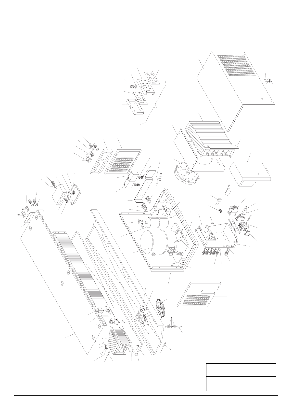
22
1 DB121 / 123
18/05/99 Arfini
Tav n° Modello :
Data : Disegnatore :
75
71
72
46
73
74
61
60
9
8
5
4
11
17
13
14
9
8
9
8
63
62
37
6
11
64
6659
26
28
7
27
69
68
29
33
41
3
2
50
51
44
45
33
49
65
52
47
19
12
39
21
20
23
54
53
41
35
31
18
48
76
79
15
9
8
16
40
42
10
30
32
1
25
55
38
80
78
3634
43
24
70
14
13
67
58
57
56
77
67
Page 13

MDB121NO170F
MDB121TO170F
BDB121NO170F
BDB121TO170F
MDB123TO170F
BDB123TO170F
1 UNIT BASE FRAME RAHMENGESTELL BASE BASAMENTO 2225070/A 1 1 1 1 1 1
3CMP648 1
3CMP644 1
2 COMPRESSOR KOMPRESSOR COMPRESSEUR COMPRESSORE 3CMP369 1
3CMP373 1
3CMP372 1
3CMP650 1
3 RECEIVER SAMMLER RESERVOIR SERBATOIO 3ACL059 1 1 1 1 1 1
4 VALVE VENTIL VANNE RUBINETTO 2RBN083 1 1 1 1 1 1
5 VALVE VENTIL VANNE RUBINETTO 2RBN084 1 1 1 1 1 1
6 SUPPORT HALTERUNG SUPPORT SUPPORTO 2009098 1 1 1 1 1 1
7 RIGHT-HAND SIDE RECHTE SEITENWAND FLANC DROIT FIANCO DESTRO 2225089 1 1 1 1 1 1
8 NUT MUTTER ECROU DADO 3DDO047 14 14 14 14 14 14
9 CABLE GLAND KABELSCHELLE SERRE-CÅBLE PRESSACAVO 3PRC027 14 14 14 14 14 14
10 SUPPORT HALTERUNG SUPPORT SUPPORTO 2009103 1 1 1 1 1 1
11 JUNCTION BOX ANSCHLUSSDOSE BOITE CONNEXION SCATOLA CONNESSIONI 3CSD008 1 1 1 1 1 1
12 MOTOR MOTOR MOTEUR MOTORE 3MVN003 1 1 1 1 1 1
13 NUT MUTTER ECROU DADO 3DDO045 6 6 6 6 6 6
14 CABLE GLAND KABELSCHELLE SERRE-CABLE PRESSACAVO 3PRC025 6 6 6 6 6 6
15 NUT MUTTER ECROU DADO 3DDO048 1 1 1 1 1 1
16 CABLE GLAND KABELSCHELLE SERRE-CABLE PRESSACAVO 3PRC028 1 1 1 1 1 1
17 TERMINAL BOX SIDE KLEMMKASTENWAND PAROI BORNIER PARETE MORSETTIERA 3ELE002 1 1 1 1 1 1
18 TERMINAL BOARD KLEMMKASTEN BOITE A’BORNES MORSETTIERA 3MOR011 1 1 1 1 1 1
19 H/P SWITCH HOCHDRUCKSCHALTER PRESSOSTAT H.P. PRESSOSTATO MAX 3PRS025 1 1 1 1 1 1
20 SHROUD LUFTLEITER CONVEYEUR D’AIR CONVOGLIATORE 2125055/A 1 1 1 1 1 1
21 CONDENSER KONDENSATOR CONDENSEUR CONDENSATORE 3CND176 1 1 1 1 1 1
22 COVER ABDECKUNG COUVERCLE COPERCHIO 2125078 1 1 1 1 1 1
23 DEFLECTOR SWITCH ABLEITER DETOURNEUR DEVIATORE 2125058 1 1 1 1 1 1
24 BOTTOM E. P. SCHALTTAFELSBODEN FOND T. E. FONDO Q. E. 2012044 1 1 1 1 1 1
25 COVER E. P. ABDECKUNG COUVERCLE A. E. COPERCHIO Q. E. 2012045 1 1 1 1 1 1
26 SWITCH L/P PRESSOSTAT MIN PRESSOS. BAS. PRES. PRESSOSTATO MIN 3PRS011 1 1 1 1 1 1
27 VALVE VENTIL VANNE RUBINETTO 3RBN101 1 1 1 1 1 1
28 PRESSURE SWITCH DRUCKSCHALTER PRESSOSTAT PRESSOSTATO 3PRS006 1 1 1 1 1 1
29 SUPPORT HALTERUNG SUPPORT SUPPORTO 2125060 1 1 1 1 1 1
30 FILTER FILTER FILTRE FILTRO 3FLT036 1 1 1 1 1 1
31 HEATER HEIZELEMENT RESISTANCE RESISTENZA 3RST022 1 1 1 1 1 1
32 SUPPORT PLATE HALTERUNGSPLATTE PLAQUE SUPPORT PIASTRA SUPP. 2125079 1 1 1 1 1 1
33 VALVE VENTIL VANNE RUBINETTO 3RBN096 2 2 2 2 2 2
34 SELECTOR WÄHLER SECTIONNEUR SEZIONATORE 3ING034 1 1 1 1 1 1
35 PRINTED CARD PRINTPLATTE. CARTE ELECTRONIQUE CENTRALINA
3SCH018 1 1 1
3SCH019 1 1 1
36 EXTENSION VERLÄNGERUNG RALLONGE PROLUNGA 3PRL009 1 1 1 1 1 1
37 TERMINAL KLEMME BORNE MORSETTO 3MOR010 8 8 8 8 8 8
38 CONTACTOR FERNSCHALTER TELERUPTEUR TELERUTTORE 3TLR191 1 1 1 1 1 1
39 HANDLE HANDGRIFF POIGNÉE MANIGLIA 3MNG009 1 1 1 1 1 1
40 LEFT-HAND SIDE LINKE SEITENWAND FLANC GAUCHE FIANCO SINISTRO 2225072 1 1 1 1 1 1
41 REINFORCEMENT VERSTÄRKUNG RENFORCEMENT RINFORZO 2009093 2 2 2 2 2 2
42 SIGHT GLASS SCHAUGLAS VOYANT LIQUIDE INDICATORE 3INU019 1 1 1 1 1 1
43 TERMINAL KLEMME BORNE MORSETTO 3MRS004 1 1 1 1 1 1
44 NUT MUTTER ECROU DADO 3DDO043 2 2 2 2 2 2
45 CABLE GLAND KABELSCHELLE SERRE-CABLE PRESSACAVO 3PRC023 2 2 2 2 2 2
46 COVER DECKEL COUVERCLE COPERCHIO QUADRO 2012032 1 1 1 1 1 1
47 KEYPAD TASTATURFOLIE SERIGRAPHIE SERIGRAFIA 3PNP037 1 1 1 1 1 1
48 VARISTOR VARISTOR VARISTEUR VARISTORE 3VRS008 1 1 1 1 1 1
49 REMOTE CONTROL FERNBEDIENUNG PANNEAU CONTROLE PANNELLO REMOTO 2PRM226 1 1 1 1 1 1
50 FAN GUARD GITTER GRILLE GRIGLIA 2GRI029 1 1 1 1 1 1
51 MOTOR DRIVEN FAN MOTORLÜFTER MOTOVENTILATEUR VENTOLA 3VNT010 1 1 1 1 1 1
52 FAN GUARD GITTER GRILLE GRIGLIA EVAP. 3GRI028 1 1 1 1 1 1
53 FAN GUARD GITTER GRILLE GRIGLIA 3GRI046 1 1 1 1 1 1
54 FAN LÜFTER VENTILATEUR VENTOLA 3VNT013 1 1 1 1 1 1
55 SUPPORT HALTERUNG SUPPORT SUPPORTO 2012047 1 1 1 1 1 1
56 DRIP TRAY TROPFSCHALE BAC ECOULEMENT BACINELLA 2121005 1 1 1 1 1 1
57 SPRING FEDER RESSORT MOLLA 3001223 4 4 4 4 4 4
58 HEATER HEIZELEMENT RESISTANCE RESISTENZA 3RST018 1 1 1 1 1 1
59 EVAPORATOR VERDAMPFER EVAPORATEUR EVAPORATORE 3EVP185 1 1 1 1 1 1
60 BOTTOM UNTERSEITE FOND FONDO 2012033 1 1 1 1 1 1
61 KEY BOARD TASTATUR CLAVIER TASTIERA REMOTA 3TST006 1 1 1 1 1 1
62 SOLENOID VALVE SOLENOIDVENTIL SOLENOIDE SOLENOIDE 3VLS001 1 1 1 1 1 1
63 SOLENOID COIL SOLENOIDSPULE BOBINE SOLENOIDE BOBINA SOLENOIDE 3CVS001 1 1 1 1 1 1
64 EXPANSION VALVE EXPANSIONSVENTIL DETENDEUR TERMOSTATICA
3BUL058 1 1 1
3BUL051 1 1 1
65 DRAIN LINE ABLAUF ECOULEMENT SCARICO 3SCA001 1 1 1 1 1 1
66 ORIFICE MÜNDUNG ORIFICE ORIFICIO 3ORF002 1 1 1 1 1 1
67 SENSOR SONDE SONDE SONDA 3SNS033 2 2 2 2 2 2
68 MOTOR MOTOR MOTEUR MOTORE 3MVN002 1 1 1 1 1 1
69 COVER ABDECKUNG COUVERCLE COPER.EVAP. 2121004/A 1 1 1 1 1 1
70 BOTTOM UNTERSEITE FOND FONDO EVAP. 2121003/A 1 1 1 1 1 1
71 VALVE VENTIL VANNE RUBINETTO 2RBN087 1 1 1 1 1 1
72 VALVE VENTIL VANNE RUBINETTO 2RBN088 1 1 1 1 1 1
73 NUT MUTTER ECROU DADO 3DDO046 1 1 1 1 1 1
74 CABLE GLAND KABELSCHELLE SERRE-CABLE PRESSACAVO 3PRC026 1 1 1 1 1 1
75 SUPPORT HALTERUNG SUPPORT SUPPORTO 2010080 1 1 1 1 1 1
76 FUSE SICHERUNG FUSIBLE FUSIBILE 3FSB017 1 1 1 1 1 1
77 HEATER HEIZELEMENT RESISTANCE RESISTENZA 3RST013 1 1 1
78 RELAY RELAIS RELAIS RELE’ 3RLM051 1 1 1 1 1 1
79 RELAY BASE RELAISSOCKEL SUPPORT RELAIS ZOCCOLO RELE’ 3ZCC015 1 1 1 1 1 1
80 RELAY SPRING RELAIS FEDER RESSORT RELAIS MOLLA RELE’ 3MOL009 1 1 1 1 1 1
25
Code-Code
Code-Codice
Pos.
Description - Beschreibung - Description - Descrizione
English Deutsch Francais Italiano
Tav
.n° 1
DB 121 / DB 123
LEGEND - LEGENDE - LEGENDE - LEGENDA :
Page 14

26
74
2 DB 221
18/05/99 Arfini
Tav n° Modello :
Data : Disegnatore :
61
73
46
47
39
71
72
60
49
20
9
8
5
4
37
11
17
13
9
8
9
8
11
14
7
6
54
53
78
19
42
10
26
28
27
44
45
33
29
33
41
3
30
12
32
21 22
35
18
48
76
80
23
25
55
38
81
79
3634
75
70
63
62
14
13
67
64
66
59
58
69
57
43
2
50
56
51
68
52
65
67
31
8
41
1
77
9
15
16
40
24
Page 15

MDB221TO170F
BDB221NO170F
BDB221TO170F
27
Code-Code
Code-Codice
Pos.
Description - Beschreibung - Description - Descrizione
English Deutsch Francais Italiano
LEGEND - LEGENDE - LEGENDE - LEGENDA :
Tav.n° 2
DB 221
1 UNIT BASE FRAME RAHMENGESTELL BASE BASAMENTO 2225070/B 1 1 1
3CMP667 1
2 COMPRESSOR KOMPRESSOR COMPRESSEUR COMPRESSORE
3CMP372 1
3CMP382 1
3 RECEIVER SAMMLER RESERVOIR SERBATOIO 3ACL006 1 1 1
4 VALVE VENTIL VANNE RUBINETTO 2RBN081 1 1 1
5 VALVE VENTIL VANNE RUBINETTO 2RBN082 1 1 1
6 SUPPORT HALTERUNG SUPPORT SUPPORTO 2009098 1 1 1
7 RIGHT-HAND SIDE RECHTE SEITENWAND FLANC DROIT FIANCO DESTRO 2225089 1 1 1
8 NUT MUTTER ECROU DADO 3DDO047 14 14 14
9 CABLE GLAND KABELSCHELLE SERRE-CÅBLE PRESSACAVO 3PRC027 14 14 14
10 SUPPORT HALTERUNG SUPPORT SUPPORTO 2009102 1 1 1
11 JUNCTION BOX ANSCHLUSSDOSE BOITE CONNEXION SCATOLA CONNESSIONI 3CSD008 1 1 1
12 MOTOR MOTOR MOTEUR MOTORE 3MVN003 1 1 1
13 NUT MUTTER ECROU DADO 3DDO045 7 7 7
14 CABLE GLAND KABELSCHELLE SERRE-CABLE PRESSACAVO 3PRC025 7 7 7
15 NUT MUTTER ECROU DADO 3DDO048 1 1 1
16 CABLE GLAND KABELSCHELLE SERRE-CABLE PRESSACAVO 3PRC028 1 1 1
17 TERMINAL BOX SIDE KLEMMKASTENWAND PAROI BORNIER PARETE MORSETTIERA 3ELE002 1 1 1
18 TERMINAL BOARD KLEMMKASTEN BOITE A’BORNES MORSETTIERA 3MOR011 1 1 1
19 H/P SWITCH HOCHDRUCKSCHALTER PRESSOSTAT H.P. PRESSOSTATO MAX 3PRS025 1 1 1
20 SHROUD LUFTLEITER CONVEYEUR D’AIR CONVOGLIATORE 2225074/A 1 1 1
21 CONDENSER KONDENSATOR CONDENSEUR CONDENSATORE 3CND177 1 1 1
22 COVER ABDECKUNG COUVERCLE COPERCHIO 2225096 1 1 1
23 DEFLECTOR SWITCH ABLEITER DETOURNEUR DEVIATORE 2225077 1 1 1
24 BOTTOM E. P. SCHALTTAFELSBODEN FOND T. E. FONDO Q. E. 2012044 1 1 1
25 COVER E. P. ABDECKUNG COUVERCLE A. E. COPERCHIO Q. E. 2012045 1 1 1
26 SWITCH L/P PRESSOSTAT MIN PRESSOS. BAS. PRES. PRESSOSTATO MIN 3PRS011 1 1 1
27 VALVE VENTIL VANNE RUBINETTO 3RBN102 1 1 1
28 PRESSURE SWITCH DRUCKSCHALTER PRESSOSTAT PRESSOSTATO 3PRS006 1 1 1
29 SUPPORT HALTERUNG SUPPORT SUPPORTO 2225095 1 1 1
30 FILTER FILTER FILTRE FILTRO 3FLT041 1 1 1
31 HEATER HEIZELEMENT RESISTANCE RESISTENZA
3RST022 1 1
3RST014 1
32 SUPPORT PLATE HALTERUNGSPLATTE PLAQUE SUPPORT PIASTRA SUPP. 2009094 1 1 1
33 VALVE VENTIL VANNE RUBINETTO 3RBN096 2 2 2
3ING025 1
34 SELECTOR WÄHLER SECTIONNEUR SEZIONATORE 3ING034 1
3ING026 1
35 PRINTED CARD PRINTPLATTE. CARTE ELECTRONIQUE CENTRALINA
3SCH018 1
3SCH019 1 1
36 EXTENSION VERLÄNGERUNG RALLONGE PROLUNGA 3PRL009 1 1 1
37 TERMINAL KLEMME BORNE MORSETTO 3MOR010 8 8 8
38 CONTACTOR FERNSCHALTER TELERUPTEUR TELERUTTORE 3TLR191 1 1 1
39 HANDLE HANDGRIFF POIGNÉE MANIGLIA 3MNG009 1 1 1
40 LEFT-HAND SIDE LINKE SEITENWAND FLANC GAUCHE FIANCO SINISTRO 2225072 1 1 1
41 REINFORCEMENT VERSTÄRKUNG RENFORCEMENT RINFORZO 2009093 2 2 2
42 SIGHT GLASS SCHAUGLAS VOYANT LIQUIDE INDICATORE 3INU006 1 1 1
43 TERMINAL KLEMME BORNE MORSETTO 3MRS004 1 1 1
44 NUT MUTTER ECROU DADO 3DDO043 2 2 3
45 CABLE GLAND KABELSCHELLE SERRE-CABLE PRESSACAVO 3PRC023 2 2 3
46 COVER DECKEL COUVERCLE COPERCHIO QUADRO 2012032 1 1 1
47 KEYPAD TASTATURFOLIE SERIGRAPHIE SERIGRAFIA 3PNP037 1 1 1
48 VARISTOR VARISTOR VARISTEUR VARISTORE 3VRS008 1 1 1
49 REMOTE CONTROL FERNBEDIENUNG PANNEAU CONTROLE PANNELLO REMOTO 2PRM226 1 1 1
50 FAN GUARD GITTER GRILLE GRIGLIA 2GRI029 2 2 2
51 MOTOR DRIVEN FAN MOTORLÜFTER MOTOVENTILATEUR VENTOLA 3VNT010 2 2 2
52 FAN GUARD GITTER GRILLE GRIGLIA EVAP. 3GRI028 2 2 2
53 FAN GUARD GITTER GRILLE GRIGLIA 3GRI048 1 1 1
54 FAN LÜFTER VENTILATEUR VENTOLA 3VNT017 1 1 1
55 SUPPORT HALTERUNG SUPPORT SUPPORTO 2012047 1
56 DRIP TRAY TROPFSCHALE BAC ECOULEMENT BACINELLA 2221005 1 1 1
57 SPRING FEDER RESSORT MOLLA 3001223 4 4 4
58 HEATER HEIZELEMENT RESISTANCE RESISTENZA 3RST019 1 1 1
59 EVAPORATOR VERDAMPFER EVAPORATEUR EVAPORATORE 3EVP187 1 1 1
60 BOTTOM UNTERSEITE FOND FONDO 2012033 1 1 1
61 KEY BOARD TASTATUR CLAVIER TASTIERA REMOTA 3TST006 1 1 1
62 SOLENOID VALVE SOLENOIDVENTIL SOLENOIDE SOLENOIDE 3VLS002 1 1 1
63 SOLENOID COIL SOLENOIDSPULE BOBINE SOLENOIDE BOBINA SOLENOIDE 3CVS001 1 1 1
64 EXPANSION VALVE EXPANSIONSVENTIL DETENDEUR TERMOSTATICA
3BUL058 1
3BUL051
11
65 DRAIN LINE ABLAUF ECOULEMENT SCARICO 3SCA001 1 1 1
66 ORIFICE MÜNDUNG ORIFICE ORIFICIO 3ORF003 1 1 1
67 SENSOR SONDE SONDE SONDA 3SNS033 2 2 2
68 MOTOR MOTOR MOTEUR MOTORE 3MVN002 2 2 2
69 COVER ABDECKUNG COUVERCLE COPER.EVAP. 2221004/A 1 1 1
70 BOTTOM UNTERSEITE FOND FONDO EVAP. 2221003/A 1 1 1
71 VALVE VENTIL VANNE RUBINETTO 2RBN085 1 1 1
72 VALVE VENTIL VANNE RUBINETTO 2RBN086 1 1 1
73 NUT MUTTER ECROU DADO 3DDO046 1 1 1
74 CABLE GLAND KABELSCHELLE SERRE-CABLE PRESSACAVO 3PRC026 1 1 1
75 SUPPORT HALTERUNG SUPPORT SUPPORTO 2010080 1 1 1
76 FUSE SICHERUNG FUSIBLE FUSIBILE 3FSB017 1 1 1
77 HEATER HEIZELEMENT RESISTANCE RESISTENZA 3RST013 1 1
78 SUPPORT HALTERUNG SUPPORT SUPPORTO 2225094 1 1 1
79 RELAY RELAIS RELAIS RELE’ 3RLM051 1 1 1
80 RELAY BASE RELAISSOCKEL SUPPORT RELAIS ZOCCOLO RELE’ 3ZCC015 1 1 1
81 RELAY SPRING RELAIS FEDER RESSORT RELAIS MOLLA RELE’ 3MOL009 1 1 1
Page 16
28
22
3 DB 135
18/05/99 Arfini
Tav n° Modello :
Data : Disegnatore :
71
75
72
46
73
74
61
60
9
8
5
4
37
11
11
17
13
14
9
8
9
8
7
6
28
26
29
33
41
27
3
2
69
44
45
33
49
47
19
20
12
42
10
30
32
41
21
35
31
18
48
76
39
23
25
38
80
78
79
15
9
8
16
24
3634
43
70
63
62
14
13
64
66
596758
57
50
56
68
51
1
52
65
77
67
40
Page 17

1 UNIT BASE FRAME RAHMENGESTELL BASE BASAMENTO 2135201/B 1 1 1 1
3CMP374 1
2 COMPRESSOR KOMPRESSOR COMPRESSEUR COMPRESSORE 3CMP548 1
3CMP382 1
3CMP368 1
3 RECEIVER SAMMLER RESERVOIR SERBATOIO 3ACL006 1 1 1 1
4 VALVE VENTIL VANNE RUBINETTO 2RBN081 1 1 1 1
5 VALVE VENTIL VANNE RUBINETTO 2RBN082 1 1 1 1
6 SUPPORT HALTERUNG SUPPORT SUPPORTO 2009098 1 1 1 1
7 RIGHT-HAND SIDE RECHTE SEITENWAND FLANC DROIT FIANCO DESTRO 2135232 1 1 1 1
8 NUT MUTTER ECROU DADO 3DDO047 14 14 14 14
9 CABLE GLAND KABELSCHELLE SERRE-CÅBLE PRESSACAVO 3PRC027 14 14 14 14
10 SUPPORT HALTERUNG SUPPORT SUPPORTO 2009102 1 1 1 1
11 JUNCTION BOX ANSCHLUSSDOSE BOITE CONNEXION SCATOLA CONNESSIONI 3CSD008 1 1 1 1
12 ELECTRIC MOTOR ELEKTROMOTOR MOTEUR ELECTRIQUE MOTOVENTILATORE 3MTV099 1 1 1 1
13 NUT MUTTER ECROU DADO 3DDO045 8 8 8 8
14 CABLE GLAND KABELSCHELLE SERRE-CABLE PRESSACAVO 3PRC025 8 8 8 8
15 NUT MUTTER ECROU DADO 3DDO048 1 1 1 1
16 CABLE GLAND KABELSCHELLE SERRE-CABLE PRESSACAVO 3PRC028 1 1 1 1
17 TERMINAL BOX SIDE KLEMMKASTENWAND PAROI BORNIER PARETE MORSETTIERA 3ELE002 1 1 1 1
18 TERMINAL BOARD KLEMMKASTEN BOITE A’BORNES MORSETTIERA 3MOR011 1 1 1 1
19 H/P SWITCH HOCHDRUCKSCHALTER PRESSOSTAT H.P. PRESSOSTATO MAX 3PRS025 1 1 1 1
20 SHROUD LUFTLEITER CONVEYEUR D’AIR CONVOGLIATORE 2135209/A 1 1 1 1
21 CONDENSER KONDENSATOR CONDENSEUR CONDENSATORE 3CND178 1 1 1 1
22 COVER ABDECKUNG COUVERCLE COPERCHIO 2135238 1 1 1 1
23 DEFLECTOR SWITCH ABLEITER DETOURNEUR DEVIATORE 2135206 1 1 1 1
24 BOTTOM E. P. SCHALTTAFELSBODEN FOND T. E. FONDO Q. E. 2012044 1 1 1 1
25 COVER E. P. ABDECKUNG COUVERCLE A. E. COPERCHIO Q. E. 2012045 1 1 1 1
26 SWITCH L/P PRESSOSTAT MIN PRESS. BAS. PRES. PRESSOSTATO MIN 3PRS011 1 1 1 1
27 VALVE VENTIL VANNE RUBINETTO 3RBN102 1 1 1 1
28 PRESSURE SWITCH DRUCKSCHALTER PRESSOSTAT PRESSOSTATO 3PRS006 1 1 1 1
29 SUPPORT HALTERUNG SUPPORT SUPPORTO 2135237 1 1 1 1
30 FILTER FILTER FILTRE FILTRO 3FLT041 1 1 1 1
31 HEATER HEIZELEMENT RESISTANCE RESISTENZA
3RST014 1 1 1
3RST022 1
32 SUPPORT PLATE HALTERUNGSPLATTE PLAQUE SUPPORT PIASTRA SUPP. 2009094 1 1 1 1
33 VALVE VENTIL VANNE RUBINETTO 3RBN096 2 2 2 2
34 SELECTOR WÄHLER SECTIONNEUR SEZIONATORE
3ING025 1 1
3ING026 1 1
35 PRINTED CARD PRINTPLATTE. CARTE ELECTRONIQUE CENTRALINA
3SCH018 1 1
3SCH019 1 1
36 EXTENSION VERLÄNGERUNG RALLONGE PROLUNGA 3PRL009 1 1 1 1
37 TERMINAL KLEMME BORNE MORSETTO 3MOR010 8 8 8 8
38 CONTACTOR FERNSCHALTER TELERUPTEUR TELERUTTORE 3TLR191 1 1 1 1
39 HANDLE HANDGRIFF POIGNÉE MANIGLIA 3MNG009 1 1 1 1
40 LEFT-HAND SIDE LINKE SEITENWAND FLANC GAUCHE FIANCO SINISTRO 2135203 1 1 1 1
41 REINFORCEMENT VERSTÄRKUNG RENFORCEMENT RINFORZO 2009093 2 2 2 2
42 SIGHT GLASS SCHAUGLAS VOYANT LIQUIDE INDICATORE 3INU006 1 1 1 1
43 TERMINAL KLEMME BORNE MORSETTO 3MRS004 1 1 1 1
44 NUT MUTTER ECROU DADO 3DDO043 3 3 3 2
45 CABLE GLAND KABELSCHELLE SERRE-CABLE PRESSACAVO 3PRC023 3 3 3 2
46 COVER DECKEL COUVERCLE COPERCHIO QUADRO 2012032 1 1 1 1
47 KEYPAD TASTATURFOLIE SERIGRAPHIE SERIGRAFIA 3PNP037 1 1 1 1
48 VARISTOR VARISTOR VARISTEUR VARISTORE 3VRS008 1 1 1 1
49 REMOTE CONTROL FERNBEDIENUNG PANNEAU CONTROLE PANNELLO REMOTO 2PRM226 1 1 1 1
50 FAN GUARD GITTER GRILLE GRIGLIA 2GRI029 3 3 3 3
51 MOTOR DRIVEN FAN MOTORLÜFTER MOTOVENTILATEUR VENTOLA 3VNT010 3 3 3 3
52 FAN GUARD GITTER GRILLE GRIGLIA EVAP. 3GRI028 3 3 3 3
56 DRIP TRAY TROPFSCHALE BAC ECOULEMENT BACINELLA 2135314 1 1 1 1
57 SPRING FEDER RESSORT MOLLA 3001223 6 6 6 6
58 HEATER HEIZELEMENT RESISTANCE RESISTENZA 3RST020 1 1 1 1
59 EVAPORATOR VERDAMPFER EVAPORATEUR EVAPORATORE 3EVP186 1 1 1 1
60 BOTTOM UNTERSEITE FOND FONDO 2012033 1 1 1 1
61 KEY BOARD TASTATUR CLAVIER TASTIERA REMOTA 3TST006 1 1 1 1
62 SOLENOID VALVE SOLENOIDVENTIL SOLENOIDE SOLENOIDE 3VLS002 1 1 1 1
63 SOLENOID COIL SOLENOIDSPULE BOBINE SOLENOIDE BOBINA SOLENOIDE 3CVS001 1 1 1 1
64 EXPANSION VALVE EXPANSIONSVENTIL DETENDEUR TERMOSTATICA
3BUL058 1 1
3BUL05
111
65 DRAIN LINE ABLAUF ECOULEMENT SCARICO 3SCA001 1 1 1 1
66 ORIFICE MÜNDUNG ORIFICE ORIFICIO 3ORF004 1 1 1 1
67 SENSOR SONDE SONDE SONDA 3SNS033 2 2 2 2
68 MOTOR MOTOR MOTEUR MOTORE 3MVN002 3 3 3 3
69 COVER ABDECKUNG COUVERCLE COPER.EVAP. 2135313/A 1 1 1 1
70 BOTTOM UNTERSEITE FOND FONDO EVAP. 2135325/A 1 1 1 1
71 VALVE VENTIL VANNE RUBINETTO 2RBN085 1 1 1 1
72 VALVE VENTIL VANNE RUBINETTO 2RBN086 1 1 1 1
73 NUT MUTTER ECROU DADO 3DDO046 1 1 1 1
74 CABLE GLAND KABELSCHELLE SERRE-CABLE PRESSACAVO 3PRC026 1 1 1 1
75 SUPPORT HALTERUNG SUPPORT SUPPORTO 2010080 1 1 1 1
76 FUSE SICHERUNG FUSIBLE FUSIBILE 3FSB018 1 1 1 1
77 HEATER HEIZELEMENT RESISTANCE RESISTENZA 3RST013 1 1
78 RELAY RELAIS RELAIS RELE’ 3RLM051 1 1 1 1
79 RELAY BASE RELAISSOCKEL SUPPORT RELAIS ZOCCOLO RELE’ 3ZCC015 1 1 1 1
80 RELAY SPRING RELAIS FEDER RESSORT RELAIS MOLLA RELE’ 3MOL009 1 1 1 1
29
Pos.
Description - Beschreibung - Description - Descrizione
English Deutsch Francais Italiano
MDB135NO170F
MDB135TO170F
BDB135NO170F
BDB135TO170F
Tav.n° 3
DB135
Code-Code
Code-Codice
LEGEND - LEGENDE - LEGENDE - LEGENDA :
Page 18

REFRIGERA
REFRIGERA
TION DIAGRAM - KÄL
TION DIAGRAM - KÄL
TETECHNIKSCHEMA
TETECHNIKSCHEMA
- SCHEMA
- SCHEMA
FRIGORIFIQUE - SCHEMA
FRIGORIFIQUE - SCHEMA
FRIGORIFERO
FRIGORIFERO
30
DB 121 - 123 - 221 - 135
DB 121 - 123 - 221 - 135
N Description Beschreibung Description Descrizione
1 COMPRESSOR KOMPRESSOR COMPRESSEUR COMPRESSORE
2 H/P SWITCH HOCHDRUCKSCHALTER PRESSOSTAT H/P PRESSOSTATO ALTA PRESS.
3 CONDENSER KONDENSATOR CONDENSEUR CONDENSATORE
4 CONDENSER MOTOR DRIVEN FAN KOND.-MOTORVENTILATOR MOTOVENTILATEUR CONDENSEUR MOTOVENTILATORE COND.
5 LIQUID RECEIVER FLÜSSIGKEITSSAMMER RESERVOIR LIQUIDE RICEVITORE LIQUIDO
6 FILTER FILTER FILTRE FILTRO
7 SIGHT GLASS SCHAUGLAS VOYANT LIQUIDE SPIA LIQUIDO
8 VALVE VENTIL VANNE RUBINETTO
9 SOLENOID VALVE SOLENOIDVENTIL SOLENOIDE SOLENOIDE
10 EXPANSION VALVE EXPANSIONVENTIL DETENDEUR THERMOSTATIQUE TERMOSTATICA
11 EVAPORATOR MOTOR DRIVEN FAN VERDAMPFER.-MOTORVENTILATOR MOTOVENTILATEUR EVAPORATEUR MOTOVENTIL.EVAPORATORE
12 EVAPORATOR VERDAMPFER EVAPORATEUR EVAPORATORE
13 DEFROST HEATER ABTAUHEIZUNG RESISTANCE DEGIVRAGE RESISTENZA SBRINAMENTO
14 DEFROST DRAIN LINE ABTAUWASSERABFLUSS ECOULEMENT EAU DEGIVRAGE SCARICO AQUA SBRINAM.
15 ROOM SENSOR RAUMSONDE SONDE CHAMBRE SONDA AMBIENTE
16 DEFROST END SENSOR ABTAUENDESONDE SONDE FIN DEGIVRAGE SONDA FINE SBRINAM.
17 COND.FAN PRESSURE SWITCH DRUCKSCHALTER (
KONDENSATORLÛFTER) PRESSOSTAT VENTIL.COND. PRESS.VENTOLA COND.
18* DRAIN LINE HEATER ABFLUSSEIZUNG RESISTANCE ECOULEMENT RESISTENZA SCARICO COND.
19 CONDENSER FAN SWITCH KOND. VENTILATORPRESSOSTAT PRESSOSTAT VENTILATEUR CONDENSEUR PRESSOSTATO VENTOLA CONDENSTORE
20 L/P SWITCH NIEDERDRUCKPRESSOSTAT PRESSOSTAT BASSE PRESSION PRESSOSTATO BASSA PRESSIONE
* Range "B" only Nur für Serie "B" Uniquement pour la gamme "B" Solo per gamma "B"
8
8
7
8
9
10
15
12
11
M
1
PF
19
PL
20
2
PH
6
4
M
5
3
8
16
1
4
1
8
13
Page 19

NNOOTTEE ((NNOOTTEESS)) :
:
31
Page 20

0MAN043/C del 04/2001
 Loading...