

Page 1

GEOTHERMAL SPLIT SYSTEMS
CARRIER
INDOOR & OUTDOOR SPLIT GEOTHERMAL
HEATING AND COOLING COMFORT SYSTEMS
GT-PX INDOOR SPLIT (50YDS) SERIES - SIZES 026-064
GT-G INDOOR SPLIT (50YCS) SERIES - SIZES 018-060
GT-S OUTDOOR SPLIT (38WQS) SERIES - SIZES 018-060
Page 2

Page 3

Indoor & Outdoor Split
Geothermal Comfort Systems
Table of Contents
Geothermal Advantages ....................................................................................................................................................................................................................................... 2
Loop Systems ............................................................................................................................................................................................................................................................. 3
GT-PX Indoor Split (50YDS) Series Introduction ................................................................................................................................................................................. 4
GT-PX Indoor Split (50YDS) Series Features & Benefi ts .................................................................................................................................................................. 5
GT-G Split Indoor (50YCS) Series Features & Benefi ts ..................................................................................................................................................................... 8
GT-S Outdoor Split (38WQS) Series Introduction .............................................................................................................................................................................10
GT-S Outdoor Split (38WQS) Series Features & Benefi ts .............................................................................................................................................................. 12
ARI/ISO/ASHRAE 13256-1 Data .................................................................................................................................................................................................................... 14
Model Nomenclature .............................................................................................................................................................................................................................................16
Reference Calculations & Legend ...................................................................................................................................................................................................................17
GT-GS/GT-S Performance Correction Factors ........................................................................................................................................................................................ 17
GT-PX Performance Correction Factors ....................................................................................................................................................................................................18
GT-PX Performance Data ................................................................................................................................................................................................................................... 19
GT-GS/GT-S Performance Data .......................................................................................................................................................................................................................27
Physical Data ...............................................................................................................................................................................................................................................................34
GT-PX Dimensional Data ....................................................................................................................................................................................................................................35
GT-GS Dimensional Data .................................................................................................................................................................................................................................... 36
GT-S Dimensional Data ........................................................................................................................................................................................................................................37
Electrical Data ............................................................................................................................................................................................................................................................. 38
Thermostat Wiring ..................................................................................................................................................................................................................................................39
CXM Control Features .........................................................................................................................................................................................................................................40
Typical Wiring Diagram - GT-PX Units ........................................................................................................................................................................................................43
Typical Wiring Diagram - GT-GS Units ........................................................................................................................................................................................................ 44
Typical Wiring Diagram - GT-S Units ............................................................................................................................................................................................................ 45
Equipment Selection ............................................................................................................................................................................................................................................... 46
Engineering Guides .................................................................................................................................................................................................................................................. 49
Accessories, Options, & Warranty .................................................................................................................................................................................................................. 52
Guide Revision Log .............................................................................................................................................................................................................................Back Cover
Revised: 08/10/05D
Carrier Indoor & Outdoor Split Geothermal Heat Pumps - Rev.: 08/10/05
1
Page 4

Carrier
Geothermal Advantages
Geothermal systems transfer heat from a build ing
to the earth in the cooling mode, or from the
earth to the building in the heating mode. Water
is used as the heat transfer medium, either in a
closed loop piping system, or by directly pumping
well water. By using this stable thermal source,
geothermal heat pumps provide energy effi cient
comfort year around.
Highest Effi ciency
The extremely high levels of effi ciency are
possible because a geothermal heat pump only
uses electricity to move heat, not produce it. A
geothermal unit typically supplies 4 kilo watts of
heat for every kilowatt of elec tric i ty used. Three of
these kilo watts of heat come directly from the ear th
itself, and are clean, free, and renewable. Overall,
geothermal technology offers the highest cooling
EER’s and heating COP’s available in the industry.
Most systems also include a hot water generator,
which diverts a portion of the supplied heat to the
domestic water heater. This provides a substantial
portion of a family’s hot water needs at a very low
cost. Overall, geothermal technology offers the
highest cooling EER’s and heating COP’s available in
the industry.
Agency (EPA) and the De part ment of Energy
(DOE). Because it is lowest in CO2 emissions,
geothermal tech nol o gy provides a solution to global
warming by primarily using the natural energy
of the earth. In contrast, traditional space
conditioning systems depend upon the exploitation
and burning of fossil energy sources with the
resultant greenhouse gas emis sions. Also, Puron®
HFC 410A refrigerant is used in the GT-PX series
equipment for minimum global warming impact and
zero ozone depletion.
Better Investment
Low life-cycle costs are provided by the low
op er at ing and maintenance costs of geothermal
systems, even when the higher initial in stal la tion costs
are considered. In new con struc tion, monthly energy
savings typically exceed the increased mort gage
payments. Therefore, cash fl ow can be positive from
the start. In retrofi t systems, a buyer who purchases
with cash usually realizes a return on in vest ment
well above certifi cate of deposit rates. And, with
equip ment life ex ceed ing 20 years, a Carrier
geothermal system is a lasting in vest ment.
Electric utilities, recognizing the dual benefi ts of
high effi ciency and low electric peak demand, often
provide incentives to purchase these systems.
Maximum Comfort
Geothermal heat pumps also provide higher
comfort levels than traditional space conditioning
equipment. By using a relatively warm source of
heat such as the earth, supply air temperatures
are signifi cantly higher in the heating mode than
traditional air-source heat pumps. Geo ther mal
heat pumps also cycle much less often than fossil
furnaces, creating a consistent indoor temperature
with comfortable relative humidity.
Environmentally Friendly
The environmental advantages of geothermal
systems have caught the eye of governmental
agencies such as the En vi ron men tal Pro tec tion
Carrier Indoor & Outdoor Split Geothermal Heat Pumps - Rev.: 08/10/05
2
Before choosing a geothermal system, many
application factors must be evaluated including:
• Ground water availability and quality
• Loop installation costs
• Land area available
• Sub-soil conditions
• Local codes
• Owner preferences
Carrier dealers have the expertise and computer
software to determine the best type of system.
Many regions have contractors specializing in the
in stal la tion of the ground loop portion of the system.
Page 5

Indoor & Outdoor Split
Geothermal Comfort Systems
Closed Loop Systems
Closed Loop Systems consist of an underground
heat exchange network of sealed, high strength
poly eth yl ene plastic pipe and a Flow Controller
pumping module. When cooling, the loop fl uid
temperature will rise, and rejected heat is dissipated
into the cooler earth. Con verse ly, while heating, the
loop fl uid temperatures fall, and heat is absorbed
from the earth. Carrier Flow Controller pumping
modules utilize small wattage pumps to circulate the
water/antifreeze fl uid within the piping system. The
plastic heat exchange loop is closed and ther mal ly
fusion-welded at all connections in the same manner
as natural gas distribution lines. Closed loops do not
require a ground water supply or drain, and they are
not subject to mineral build up.
Closed Loops can be installed in vertical or
hor i zon tal confi gurations, or submerged in a
pond or lake. When designed properly, all three
alternatives operate with similar effi ciency. Carrier
high density poly eth yl ene plastic pipe is used for all
closed loop installations. Pipe con nec tions are heat
fused to form joints that are stronger than the pipe
itself. Carrier loop piping has a life expectancy in
excess of 50 years.
Vertical Loops are the ideal choice when available
land area is limited.
Drilling equipment is
used to bore smalldiameter vertical
holes. Two pipes
joined together with
a u-bend fi tting are
inserted into the
vertical bore. Bore hole depth ranges from 100-300
feet per system ton. Bores must be spaced from
10-15 feet apart and properly grouted. The land
space required ranges from 100-200 square feet per
system ton.
Pond (Lake) Loops are very economical to install
when a body of
surface water is
available, because
ex ca va tion costs are
mostly eliminated.
Coils or “slinky” mats
of pipe are simply
placed on the bottom
of the pond (lake). In most cases, 1/4 to 1/2 acre of
water surface, with a min i mum depth of 8-10 feet, is
needed for a typical res i dence.
Horizontal Loops are often considered when
adequate land space
is available. The
pipes are placed in
trenches, excavated
by a backhoe or chain
trencher to a depth of
4-6 feet. De pend ing
on design, from 1-6
pipes are installed in each trench. Multiple pipe
and coiled “slinky” con fi g u ra tions are often used
to conserve land re quire ments and reduce overall
installed loop costs. Horizontal boring technology
can also be used to install u-bend loops 10-15 feet
deep with minimal landscaping disruption. Trench
lengths range from 100-400 feet per system ton.
Trenches must be spaced from 6-10 feet apart. The
overall land area required ranges from 750-1,500
square feet per system ton.
Carrier Indoor & Outdoor Split Geothermal Heat Pumps - Rev.: 08/10/05
Ground Water Systems
Open loop systems utilize ground water as a direct
energy source when
good quality water
is available at a
reasonable pumping
depth. A well must
have enough capacity
to deliver a minimum
of 1.5 gpm per system
ton during peak
op er a tion. Ditches, fi eld tiles, ponds and streams are
the most common discharge systems. Re in jec tion or
semi-closed recirculation wells can also be utilized
in some regions. In ideal con di tions, an open loop
ap pli ca tion can be the most eco nom i cal type of
system to install.
3
Page 6
GT-PX
Rounding Out the Product Line
Building upon the overwhelming market success of
the GT-PX packaged unit, the split system uses the
same components in a more fl exible confi guration.
The GT-PX split system compressor section can be
coupled with a variety of air handlers and add-on
furnace coils to achieve the highest effi ciencies of
any split system heat pump on the market today,
while still providing the fl exibility of an all-electric or
dual fuel system and a remote compressor section
location. Split systems are often used in areas where
it would be diffi cult to install a packaged unit, such as
in an attic or crawl space.
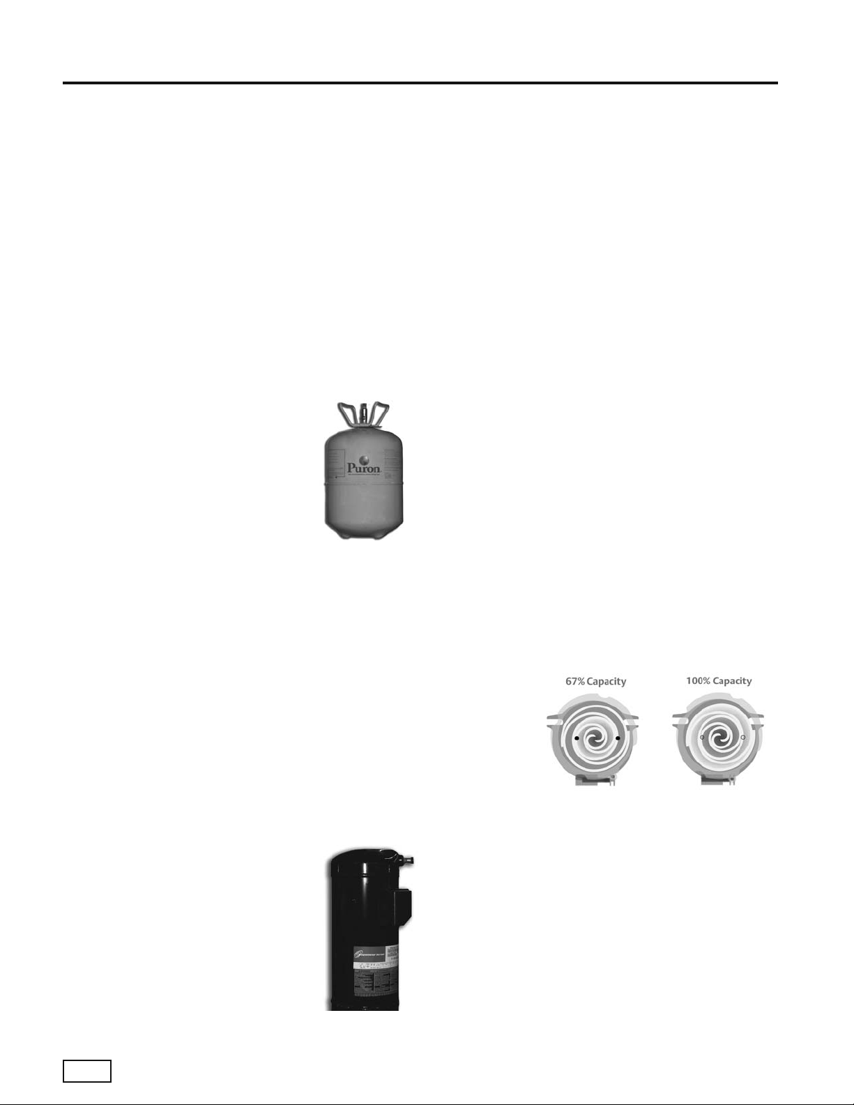
Puron® Refrigerant
Puron® is a non-chlorine based (HFC
410A) refrigerant, that with R-407C
and R-134A, is seen as the future of
all refrigerants used worldwide. HFC
410A characteristics compared to R22 are:
• Binary and near azeotropic mixture of 50% R-32
and 50% R-125.
•
Higher effi ciencies (50-60% higher
operating pressures).
• Zero ozone depletion potential and low global
warming potential.
• Virtually no glide. Unlike other alternative
refrigerants, the two components in HFC 410A
have virtually the same leak rates. Therefore,
refrigerant can be added if necessary without
recovering the charge.
Copeland Two-Stage Scroll Compressor
Achieve a greater level of comfort.
The Copeland Scroll UltraTech™
provides superior comfort than
fi xed-capacity compressors by
incorporating a revolutionary twostep design. With a unique 67%
part-load capacity step, systems
with UltraTech™ maintain precise
temperature levels and lower relative
humidity. This eliminates uneven peaks and valleys
and allows for steady cooling comfort. Homeowners
now have a better, more effi cient way to power
their heating and cooling system, raising their level of
comfort, while lowering energy bills. So when your
customers need a new heating and cooling system,
make sure it has the best technology inside – the
Copeland Scroll UltraTech™ compressor.
Save with superior effi ciency. Over 40% of summer
utility bills can come from the air conditioner
compressor operation. A system with the Copeland
Scroll UltraTech™ compressor delivers higher
effi ciency than any other single compressor system.
In fact, systems with UltraTech™ provide up to 60%
greater energy effi ciency as compared to 10 SEER
systems – which can save homeowners hundreds
of dollars a year in energy costs.
Take it easy with quieter control. Copeland
Scroll UltraTech™ is remarkably quiet at both
full- and part-load capacity. In fact, it is up to four
times quieter than a reciprocating compressor.
Homeowners can enjoy its superior effi ciency and
comfort without having to hear the operation.
Learn the beauty of the design. With Copeland Scroll
UltraTech™, two internal bypass ports enable the
system to run at 67% part-load capacity for better
effi ciency
and humidity
control. Based
on demand,
the modulation
ring is
activated,
sealing the bypass ports and instantly shifting capacity
to 100%. Take advantage of “shift on the fl y” stage
changing (no stopping and starting required like other
two-stage compressors).
Choose proven scroll performance. While Copeland
Scroll UltraTech™ builds on established scroll
technology, it is still a scroll at heart, which means
it operates with fewer moving parts, no volumetric
effi ciency drop-off or compression leakage. The result
is unsurpassed reliability and virtually silent operation
for both indoor and outdoor applications.
Carrier Indoor & Outdoor Split Geothermal Heat Pumps - Rev.: 08/10/05
4
Page 7

Two-Stage Indoor Split
Puron® Systems
Other New Features
• Stylish two-tone look with textured black powder
coat paint and stainless steel front access panel.
• Liftout handle for front access panel.
• Factory supplied (fi eld-installed) fi lter drier for
trouble free reliability.
• Easy access low profi le horizontal control box.
• Double isolated compressor for quiet and
vibration free operation.
• Spring-mounted compressor for additional
noise suppression.
• Open Service-Friendly Cabinet (i.e, all
components in compressor section can be
serviced from the front).
The GT-PX Series Split System has abundant
features and industry leading effi ciency.
Application Flexibility
• Four Capacities 026, 038, 049, and 064.
• Extended range operation (20-120°F EWT) and
fl ow rates as low as 1.5 gpm per ton.
• Compressor section match-ups for a variety of air
handlers and add-on furnace coils for the ultimate
in system and fuel type fl exibility.
• Precharged compressor section with back-seating
service valves for quick installation.
• Circuit breaker protected loop and hot water
generator pumps.
• Field selectable freeze protection setting for well
or loop.
•
Puron® HFC 410A zero ozone depletion refrigerant.
• Highest effi ciencies for split systems in ARI/ISO/
ASHRAE/ANSI 13256-1 ratings for heating COP’s,
cooling EER’s with low water fl ow rates.
• Two-Stage operation for ultra high effi ciencies and
unsurpassed comfort.
• Operating temperature range and high effi ciency
allow shorter loops.
• Optional hot water generator with internal pump
generates hot water at considerable savings.
• Rugged and highly effi cient next generation
Copeland UltraTech™ scroll compressors provide
the industry’s highest effi ciencies and full capacity
with reduced cycling losses.
• Oversized coaxial tube water-to-refrigerant heat
exchangers operate at low liquid pressure drop.
Convoluted copper (and optional cupronickel)
water tube functions effi ciently at low-fl ow rates
and provides freeze-damage resistance.
Service Advantages
• Removable panels - 3 for compressor section
(plus removable top panel).
• Low profi le control box grants easy access to all
internal components.
• Factory supplied (fi eld installed) liquid line
fi lter/drier.
• Brass swivel-type water connections for quick
connection and elimination of wrenches or
sealants during installation.
• Bi-directional thermal expansion valve.
• CXM control features status lights with memory
for easy diagnostics.
• Unit Performance Sentinel alerts homeowner of
potential performance issues.
•
Circuit breaker protected 75VA control transformer.
• High and low pressure service ports on
refrigerant circuit.
• Accurate refrigerant sensing freeze protection.
Factory Quality
• All units are built on our Integrated Process
Control Assembly System (IPCS). The IPCS is
a unique state of the art manufacturing system
that is designed to assure quality of the highest
standards of any manufacturer in the water-source
industry. Our IPCS system:
- Verifi es that the correct components are
being assembled.
Carrier Indoor & Outdoor Split Geothermal Heat Pumps - Rev.: 08/10/05
5
Page 8

GT-PX
- Automatically performs special leak tests on
all joints.
- Conducts pressure tests.
- Performs highly detailed run test unparalleled in
the HVAC industry.
- Automatically disables packaging for a “failed” unit.
- Creates computer database for future service
analysis and diagnostics from run test results.
• Heavy gauge galvanized steel cabinets are epoxy
powder coated for durable and long-lasting fi nish.
• All refrigerant brazing is done in a nitrogen
atmosphere.
• All units are deep evacuated to less than 100
microns prior to refrigerant charging.
• All joints are both helium and halogen leak tested
to insure annual leak rate of less than 1/4 ounce.
• Coaxial heat exchanger, refrigerant suction lines
and all water lines are fully insulated to eliminate
condensation problems in low temperature
applications.
• Noise Reduction features include: double isolation
mounted compressors, compressor springs,
insulated compressor compartment, and interior
cabinet insulation using 1/2” coated glass fi ber.
•
Safety features include: high pressure and loss of
charge to protect the compressor; condensate
overfl ow protection; low water temperature
limit sensors to safeguard the coaxial heat
exchanger and air coil; hot water high limit and low
compressor discharge temperature switch provided
to shut down the hot water generator when
conditions dictate. Fault lockout enables emergency
heat and prevents compressor operation until
thermostat or circuit breaker has been reset.
Advanced Unit Controls With
Easy Diagnostics And
Unit Protection Sentinel Functions
Options & Accessories
• Optional hot water generator with internally
mounted pump.
• Optional cupronickel coaxial heat exchanger.
• Electronic thermostat.
• Closed loop Flow Controller.
• Electronic auto-changeover thermostat with 3stage heat, 2-stage cool and indicator LED’s.
• Hose kits.
Carrier Indoor & Outdoor Split Geothermal Heat Pumps - Rev.: 08/10/05
6
Puron® HFC 410A Refrigerant
Page 9
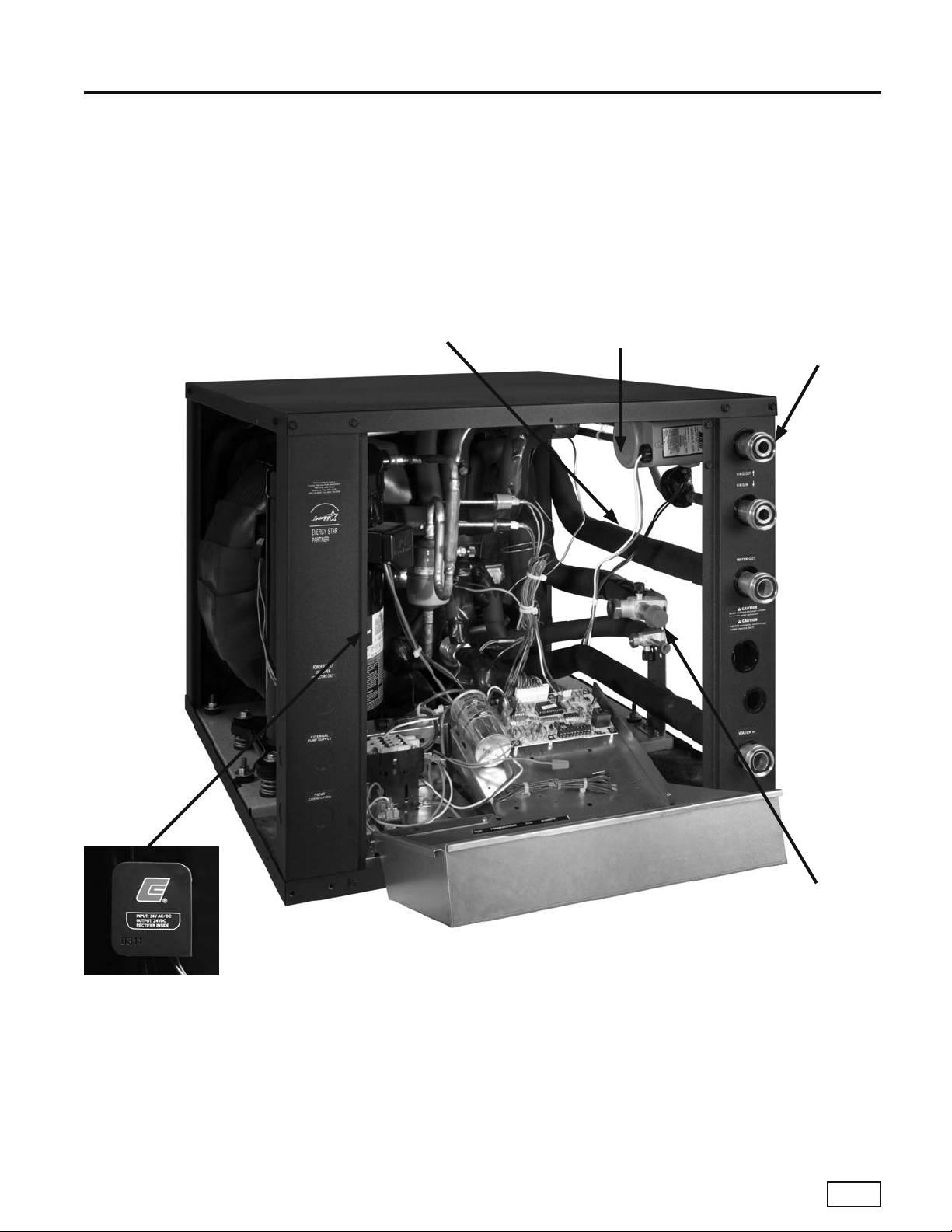
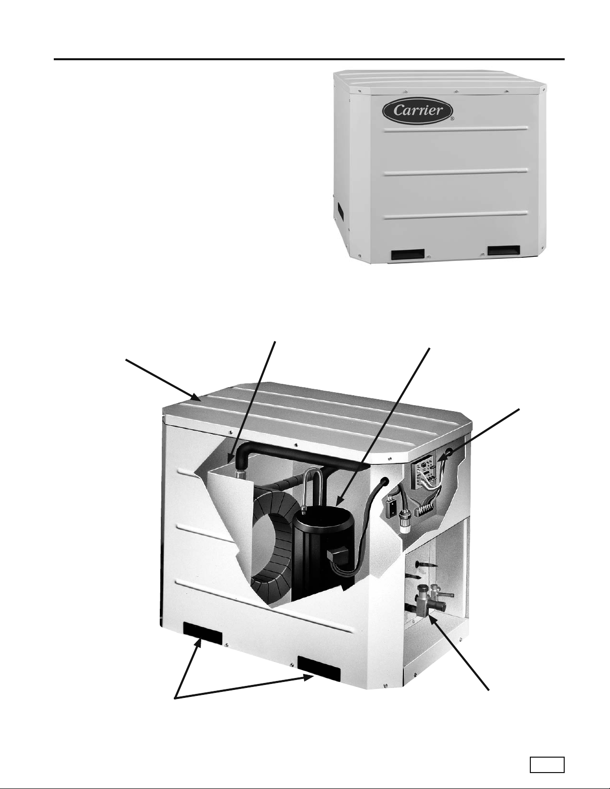
Features and Benefi ts
Three Easy, Lift-out
Service Access Panels with
Stainless Steel Front Panel
Fully Insulated
Water and
Refrigerant Lines
Two-Stage Indoor Split
Optional Factory
Installed Hot Water
Genorator With
Internal Pump
Puron® Systems
Brass Swivel
Water Connections
Oversized
Water Coil
Two-Stage Copeland
UltraTech™ Unloading
Scroll Compressor
Low Profi le Control Box
Backseating Brass
Service Valves with
Service Port
Carrier Indoor & Outdoor Split Geothermal Heat Pumps - Rev.: 08/10/05
7
Page 10

GT-GS
Application Flexibility
• Eight Capacities 018, 024, 030, 036, 042, 048,
and 060.
• Voltage availability in 208-230/60/1.
• Stackable cabinets.
• Extended range operation (20-120°F EWT) and
fl ow rates as low as 1.5 gpm per ton.
• Circuit breaker protected loop and hot water
gen er a tor pumps.
• Field selectable low temperature cut-out selection
setting for well or loop.
• Corner located electrical box for wiring access
from two sides.
• Compressor mounting springs “matched” to each
compressor for maximum quietness.
• Narrow cabinet for movement through doorways.
• Precharged refrigerant circuit with backseating
service valves for quick installation.
Operating Effi ciencies
• ARI/ASHRAE/ISO 13256-1 ratings for heating
COP’s, cooling EER’s and low water fl ow rates.
• Operating and temperature range allow
shorter loops.
• Optional hot water generator with internal pump
generates hot water at considerable savings.
• Rugged, super quiet, and highly effi cient
scroll compressors.
• Oversized coaxial tube water to refrigerant heat
exchangers operate at low liquid pressure drop.
• Convoluted copper (and optional cupronickel)
water tube functions effi ciently at low-fl ow rates
and provides freeze-damage resistance.
Service Advantages
• Removable panels-3 for compressor.
• Brass swivel-type water and HWG connections
for quick connection and elimination of wrenches
or sealants during installation.
Solid state digital compressor module provides
•
reliable lockout, diagnostic, and time delay functions.
• High side loss-of-charge sensing reduces nuisance
low pressure faults.
• LED Fault and status indication with memory for
easy diagnostics.
Designed for front-access service in tight ap pli ca tions.
•
• High and low pressure service ports in the
refrigerant circuit.
• Refrigerant sensing freeze protection for more
accurate low temperature cut-out.
Factory Quality
• All units are built on our Integrated Process
Control Assembly System (IPCS). The IPCS is
a unique state of the art manufacturing system
that is designed to assure quality of the highest
standards of any manufacturer in the water-source
industry. Our IPCS system:
- Verifi es that the correct components are
being assembled.
- Automatically performs special leak tests on
all joints.
- Conducts pressure tests.
- Performs highly detailed run test unparalleled in
the HVAC industry.
Automatically disables packaging for a “failed” unit.
-
- Creates computer database for future service
analysis and diagnostics from run test results.
• Heavy gauge galvanized steel cabinets are epoxy
powder coated for durable and long-lasting fi nish.
• All refrigerant brazing is done in a nitrogen
atmosphere.
• All units are deep evacuated to less than 100
microns prior to refrigerant charging.
• All joints are both helium and halogen leak tested
to insure annual leak rate of less than 1/4 ounce.
• Coaxial heat exchanger, refrigerant suction lines
and all water lines are fully insulated to eliminate
condensation problems in low temperature
applications.
• Noise Reduction features include: double isolation
mounted compressors, compressor springs,
insulated compressor compartment, and interior
cabinet insulation using 1/2” coated glass fi ber.
Safety features include: high pressure and loss of
•
charge to protect the compressor; condensate
overfl ow protection; low water temperature
limit sensors to safeguard the coaxial heat
exchanger and air coil; hot water high limit and low
compressor discharge temperature switch provided
to shut down the hot water generator when
conditions dictate. Fault lockout enables emergency
and prevents compressor operation until
heat
thermostat or circuit breaker has been reset.
Carrier Indoor & Outdoor Split Geothermal Heat Pumps - Rev.: 08/10/05
8
Page 11
Options & Accessories
• Optional hot water generator with internally
mounted pump.
• Optional cupronickel coaxial heat exchanger.
• Wide thermostat selection.
• Closed loop fl ow controller.
• Hose kits.
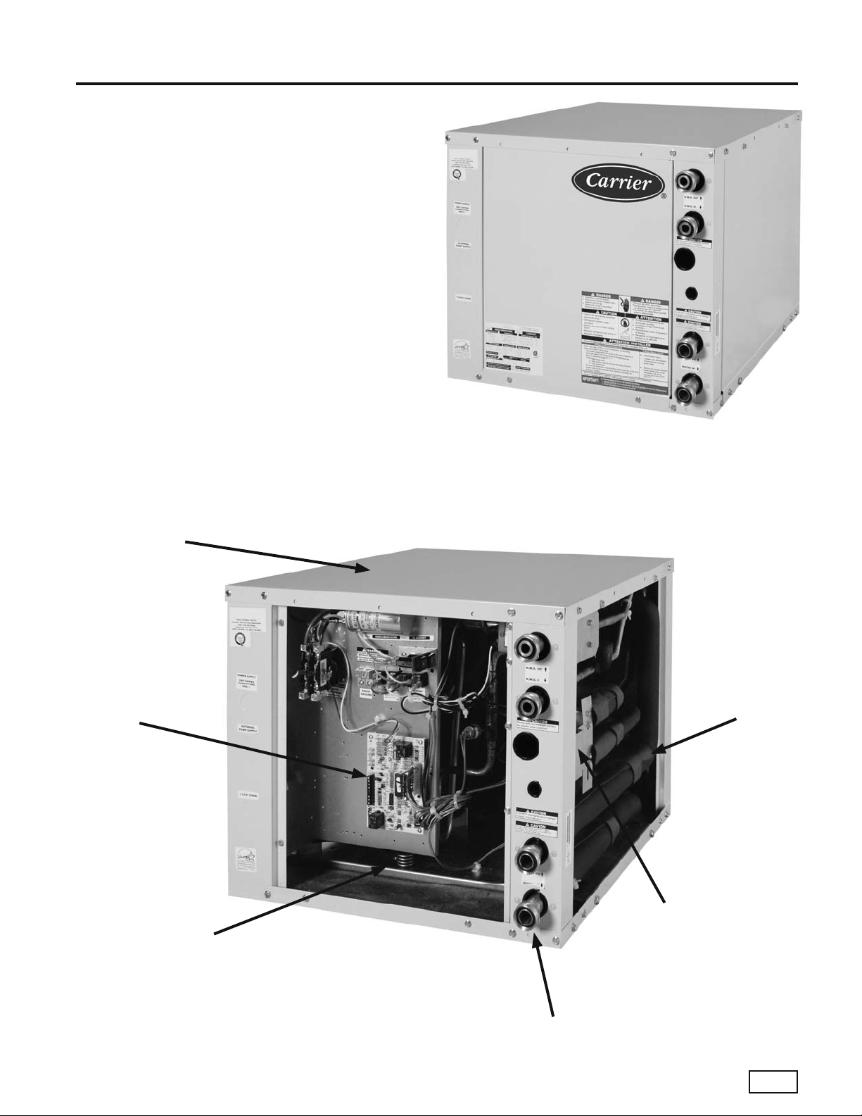
Features and Benefi ts
Single-Stage Indoor Split
R22 Systems
Epoxy Powder Coat Painted
Stackable Cabinet
Digital Controls
Easy Service Access From
Three Sides
Fully Insulated
Water and
Refrigerant Lines
Backseating Brass
Service Valves with
Service Port
Copeland Scroll Compressors
1” Brass Swivel Water Connections
Carrier Indoor & Outdoor Split Geothermal Heat Pumps - Rev.: 08/10/05
9
Page 12

GT-S
What is the GT-S?
Carrier introduced the industry to the fi rst ever
“outdoor” geothermal split system with internal
pumping for residential applications. We are giving
the consumer choices for unit location! The unit may
be installed inside or outside, thereby satisfying the
requirements of almost any home. When installed
outside, the unit may be placed on an existing pad
and easily connected to existing electric service. And
with this installation option, the fl uid loop remains
outside avoiding extensive installation inside the home.
The GT-S is geothermal without the hassle.
Why “Paradigm Shift”?
We have defi ned the paradigm shift as follows: to
advance a model of technology beyond the familiar.
But what do we mean? Essentially, our GT-S is taking
traditional geothermal technology a step fur ther
by offering a unique split system design suitable for
any home. Home owners can now enjoy all the
savings of a geothermal system with lower installation
costs and less hassle. More importantly, the GT-S is
opening up the previously illusive retrofi t market.
Hence, our slogan “From Air to Water...”. The GT-S is
a competitive product designed to shift traditional air
source homeowners to the benefi ts of water source
geothermal technology.
From the utility perspective, the
perfectly embodies what the utility industry has been
searching for in geothermal: Lower fi rst cost, simple
and easy to service, fi ts traditional dealer practices
and broad market appeal especially for retrofi t, etc.
GT-S
The
niche into more of a mainstream segment.
can pull geothermal out of its high end
GT-S
just about
The GT-S Concept
The
GT-S
provides a unique solution to many of the
problems associated with single-package geothermal
units. In addition, it substantially reduces overall
installed costs and perhaps more importantly, opens
up the largely untapped retrofi t market (which, for
conventional equipment, is over 3 times larger than
the new construction market).
In new construction, the
over packaged geothermal units: The fl uid loop is
kept outside, which keeps large diameter piping,
fl ammable antifreezes and fl ushing carts (a large,
messy service tool) out of the home. The outdoor
compressor means noise and most service activity
will remain outside. The indoor air handlers are quiet,
require less space and allow less costly ductwork
(they don’t have to be side return with canvas collars
and plenum lining). Also, a GT-S can utilize a gas
furnace as the blower and supplemental heat (dual
fuel or add-on) which removes a major consumer
barrier in that geothermal has traditionally forced the
homeowner to make an all-electric home decision.
An add-on application also allows the option of sizing
the geothermal component to the cooling load,
rather than heating, which may further reduce fi rst
GT-S
costs. The
construction segment than geothermal currently
captures, even when marketed through existing
geothermal dealers.
In the replacement market, the
the range of suitable geothermal applications. Current
geothermal retrofi ts have required a complete change
out of all existing equipment, elaborate ductwork
modifi cations, complex routing of interior loop fl uid
lines including below grade foundation penetrations,
upgraded electrical service and unit feeders (110v
furnace being changed to 240v heat pump with
electric backup), and more. This assumes that a
geothermal package unit can even be adapted to fi t
into the existing space. This process is expensive and
disruptive to the owner (they typically don’t want to
change radically from what they have); hence the lack
of geothermal retrofi ts existing. In contrast, the
S
can be installed outside on the same line set and
electric service supplying the existing air conditioner
or heat pump condensing unit. The loop stays outside.
Only the indoor coil might need to be changed on
an existing furnace, or possibly the air handler on an
older heat pump. The purchase timing could be driven
by a fi rst-time central cooling addition; the upgrade
replacement of an aging or broken air conditioner, heat
pump or furnace; an HVAC change necessitated by a
renovation; or an effi ciency upgrade driven by a utility
marketing program.
should be able to tap a larger new
GT-S
offers many benefi ts
GT-S
greatly expands
GT-
Carrier Indoor & Outdoor Split Geothermal Heat Pumps - Rev.: 08/10/05
10
Page 13
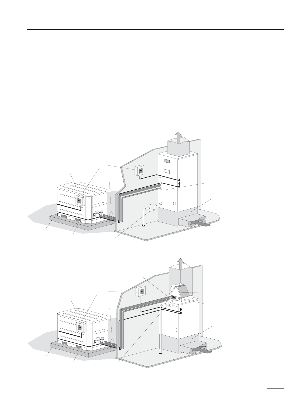
Single-Stage Outdoor Split
R22 Systems
The GT-S does not need to be located outside.
It can be placed in garages, carports, basements,
crawl spaces, etc. This may be important to some
homeowners who may be very concerned about
outdoor aesthetics. They also can utilize ground
water if placed in an appropriate indoor location.
Noise is not a problem as the GT-S is extremely
quiet (the box is sealed and insulated). The GT-S also
has excellent heating and latent cooling capacities
compared with competitive high effi ciency geothermal
units. In many cases a GT-S produces the heating
Typical GT-S / Air Handler Installation
Power
Condensing
Unit
Disconnects
Insulated line
set with UV
Paint
output of one size larger competitor unit. And the
GT-S is likely to be the highest EER per dollar cost
unit available in the geothermal industry today.
The goal for the
GT-S
Series is based upon
application fl exibility, effi ciency, reliability and a solid
state microprocessor compressor control, producing
a reliable, simple product both easy to service and
install. Its effi ciency and application fl exibility make it
the “Paradigm” of geothermal heat pumps.
Air Handler
TXV “IN” toward
outdoor
condensing Unit
Air Pad
Low Voltage Wiring
PVC Condensate
with vented trap
Typical GT-S / Add-on Coil Installation
TXV “IN” toward outdoor
condensing unit
Power
Condensing
Unit
Disconnects
Insulated line
set with
UV Paint
Fossil Furnace
Return Plenum
Add-On
“A” Coil
Air
Temperature
Limit Switch
Return Plenum
Air Pad
Low Voltage Wiring
PVC Condensate
with vented trap
Carrier Indoor & Outdoor Split Geothermal Heat Pumps - Rev.: 08/10/05
11
Page 14

GT-S
Application Flexibility
• Eight Capacities 018, 024, 030, 036, 042, 048,
and 060.
• Voltage availability in 208-230/60/1.
• Stackable cabinets.
• Extended range operation (20-120°F EWT)
and fl ow rates as low as 2.25 gpm per ton
(geothermal closed loop operation).
• Circuit breaker protected loop and hot water
gen er a tor pumps.
• Field selectable low temperature cut-out selection
setting for geothermal closed loop operation.
• Easily accessible electrical box for wiring.
• Weather-resistent cabinet.
Internally-mounted (fi eld installed) Flow Controller
•
• Precharged refrigerant circuit with backseating
service valves for quick installation.
Operating Effi ciencies
• ARI/ASHRAE/ISO 13256-1 ratings for heating
COP’s, cooling EER’s and low water fl ow rates.
• Operating and temperature range allow
shorter loops.
• Optional remoted-mounted hot water generator
with internal pump generates hot water at
considerable savings.
• Rugged, super quiet, and highly effi cient scroll
compressors (rotary for size 018).
• Oversized coaxial tube water to refrigerant heat
exchangers operate at low liquid pressure drop.
• Convoluted copper (and optional cupronickel)
water tube functions effi ciently at low-fl ow rates
and provides freeze-damage resistance.
Service Advantages
• Removable side and top panels for easy access to
water/refrigerant circuits.
• Low ambient temperature switch activates loop
pump in extreme temperatures.
Solid state digital compressor module provides
•
reliable lockout, diagnostic, and time delay functions.
• High side loss-of-charge sensing reduces nuisance
low pressure faults.
• LED Fault and status indication with memory for
easy diagnostics.
Carrier Indoor & Outdoor Split Geothermal Heat Pumps - Rev.: 08/10/05
12
• High and low pressure service ports in the
refrigerant circuit.
• Refrigerant sensing freeze protection for more
accurate low temperature cut-out.
Factory Quality
• All units are built on our Integrated Process
Control Assembly System (IPCS). The IPCS is
a unique state of the art manufacturing system
that is designed to assure quality of the highest
standards of any manufacturer in the water-source
industry. Our IPCS system:
- Verifi es that the correct components are
being assembled.
- Automatically performs special leak tests on
all joints.
- Conducts pressure tests.
- Performs highly detailed run test unparalleled in
the HVAC industry.
Automatically disables packaging for a “failed” unit.
-
- Creates computer database for future service
analysis and diagnostics from run test results.
• Heavy gauge galvanized steel cabinets are epoxy
powder coated for durable and long-lasting fi nish.
• All refrigerant brazing is done in a nitrogen
atmosphere.
• All units are deep evacuated to less than 100
microns prior to refrigerant charging.
• All joints are both helium and halogen leak tested
to insure annual leak rate of less than 1/4 ounce.
• Coaxial heat exchanger, refrigerant suction lines
and all water lines are fully insulated to eliminate
condensation problems in low temperature
applications.
• Noise Reduction features include: double isolation
mounted compressors, compressor springs,
insulated compressor compartment, and interior
cabinet insulation using 1/2” coated glass fi ber.
Safety features include: high pressure and loss of
•
charge to protect the compressor; condensate
overfl ow protection; low water temperature
limit sensors to safeguard the coaxial heat
exchanger and air coil; hot water high limit and low
compressor discharge temperature switch provided
to shut down the hot water generator when
conditions dictate. Fault lockout enables emergency
heat and prevents compressor operation until
thermostat or circuit breaker has been reset.
Page 15
Options & Accessories
• Optional remote-mounted hot water generator
with internally mounted pump.
• Optional cupronickel coaxial heat exchanger.
• Wide thermostat selection.
• Closed loop fl ow controller.
Features and Benefi ts
Single-Stage Outdoor Split
R22 Systems
Powder Coated Galvanized
Heavy Gauge Steel
Insulated Weather
Resistant Cabinet
Internally Mounted
Flow Controller
Copeland Scroll Compressor
(Rotary in 018)
Digital Controls
Hot Water
Generator Ready
Integral Carrying Handles
BackSeating Brass Service Valves
with Service port
Carrier Indoor & Outdoor Split Geothermal Heat Pumps - Rev.: 08/10/05
13
Page 16
Carrier
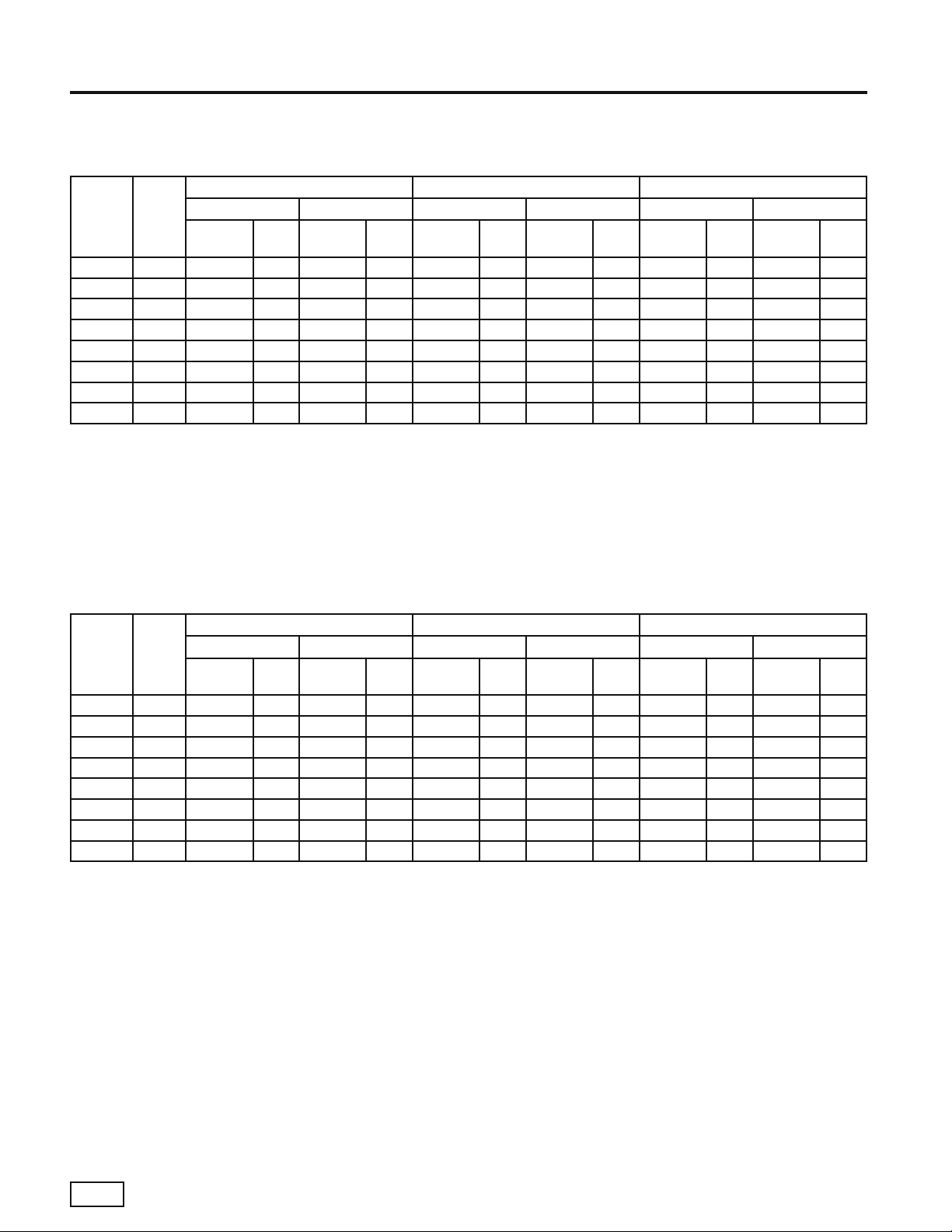
ARI/ISO/ASHRAE 13256-1
GT-PX (50YDS) Performance Data - English (IP) Units
ARI/ISO/ASHRAE 13256-1
English (IP) Units
Water Loop Heat Pump Ground Water Heat Pump Ground Loop Heat Pump
Model Load
026 Full 24,700 15.0 31,400 5.3 28,600 23.2 25,600 4.7 26,400 18.0 19,500 3.9
026 Part 18,300 16.3 24,300 5.4 22,000 29.4 19,200 4.6 20,800 24.5 16,600 4.1
038 Full 35,900 14.8 44,700 5.0 40,100 21.4 35,900 4.5 37,300 16.7 27,000 3.8
038 Part 24,400 16.5 30,300 5.6 28,000 27.1 24,400 4.6 27,100 23.7 21,400 4.1
049 Full 48,100 14.6 59,400 5.2 53,900 20.9 47,700 4.6 50,200 16.6 37,200 4.0
049 Part 33,300 16.0 42,000 5.4 38,700 26.8 33,800 4.7 37,000 22.8 29,900 4.2
064 Full 56,900 14.5 74,000 4.7 63,800 19.2 58,800 4.3 59,500 15.3 45,700 3.6
064 Part 40,800 15.8 52,700 5.2 46,000 25.7 42,300 4.4 44,800 22.2 37,500 4.0
Cooling 86°F Heating 68°F Cooling 59°F Heating 50°F Cooling 77°F Heating 32°F
Capacity
Btuh
Btuh/W
EER
Capacity
Btuh
COP
Capacity
Btuh
EER
Btuh/W
Capacity
Btuh
COP
Capacity
Btuh
EER
Btuh/W
Capacity
Btuh
COP
GT-PX (50YDS) Performance Data - Metric (SI) Units
ARI/ISO/ASHRAE 13256-1
Metric (SI) Units
Water Loop Heat Pump Ground Water Heat Pump Ground Loop Heat Pump
Model Load
026 Full 7,239 4.4 9,203 5.3 8,382 6.8 7,503 4.7 7,737 5.3 5,715 3.9
026 Part 5,363 4.8 7,122 5.4 6,448 8.6 5,627 4.6 6,096 7.2 4,865 4.1
038 Full 10,522 4.3 13,101 5.0 11,753 6.3 10,522 4.5 10,932 4.9 7,913 3.8
038 Part 7,151 4.8 8,880 5.6 8,206 7.9 7,151 4.6 7,943 6.9 6,272 4.1
049 Full 14,097 4.3 17,409 5.2 15,797 6.1 13,980 4.6 14,713 4.9 10,903 4.0
049 Part 9,760 4.7 12,309 5.4 11,342 7.9 9,906 4.7 10,844 6.7 8,763 4.2
064 Full 16,676 4.2 21,688 4.7 18,699 5.6 17,233 4.3 17,438 4.5 13,394 3.6
064 Part 11,958 4.6 15,445 5.2 13,482 7.5 12,397 4.4 13,130 6.5 10,991 4.0
Cooling capacities based upon 80.6°F DB, 66.2°F WB entering air temperature.
Heating capacities based upon 68°F DB, 59°F WB entering air temperature.
All ratings based upon 208V operation.
Cooling 30°C Heating 20°C Cooling 15°C Heating 10°C Cooling 25°C Heating 0°C
Capacity
Watts
EER
W/W
Capacity
Watts
COP
Capacity
Watts
EER
W/W
Capacity
Watts
COP
Capacity
Watts
EER
W/W
Capacity
Watts
COP
Carrier Indoor & Outdoor Split Geothermal Heat Pumps - Rev.: 08/10/05
14
Page 17
Indoor & Outdoor Split
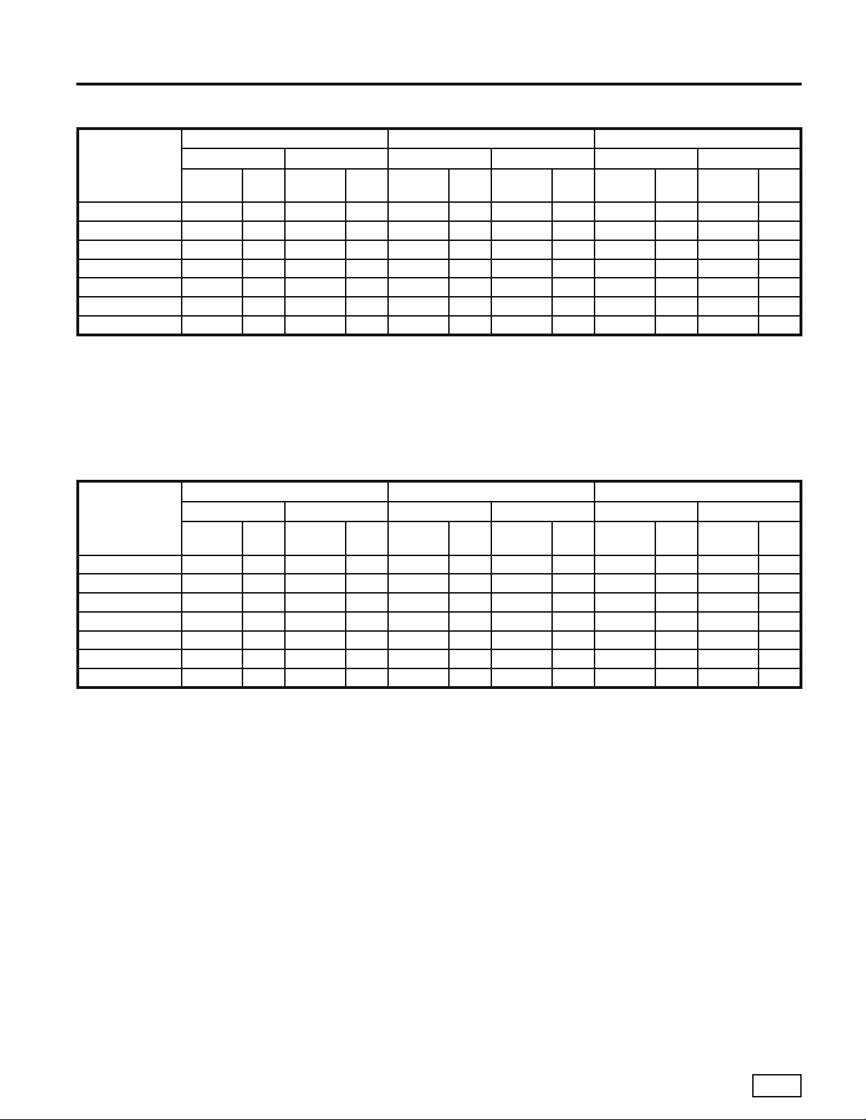
ARI/ISO/ASHRAE 13256-1
GT-GS (50YCS) & GT-S (38WQS) Performance Data - English (IP) Units
Water Loop Heat Pump Ground Water Heat Pump Ground Loop Heat Pump
Model
018 16,600 14.4 20,300 4.8 18,500 22.1 15,500 4.0 17,800 16.2 12,800 3.5
024 23,500 14.5 29,300 4.7 25,700 20.6 22,800 3.9 25,200 16.6 18,600 3.5
030 28,000 14.7 34,000 4.7 30,200 20.8 26,400 3.9 29,800 16.4 21,500 3.5
036 32,800 14.5 39,200 4.4 34,900 20.1 31,900 3.9 34,700 15.9 25,900 3.3
042 39,800 14.1 48,300 4.7 44,100 19.7 37,800 3.9 42,000 15.5 31,700 3.6
048 44,500 14.2 52,500 4.8 47,500 19.3 42,000 3.9 47,400 15.9 35,800 3.6
060 55,100 13.0 72,700 4.6 57,800 17.2 57,100 3.7 57,600 14.2 47,200 3.5
Cooling capacities based upon 80.6°F DB, 66.2°F WB entering air temperature.
Heating capacities based upon 68°F DB, 59°F WB entering air temperature.
All ratings based upon 208V operation.
Cooling 86°F Heating 68°F Cooling 59°F Heating 50°F Cooling 77°F Heating 32°F
Capacity
Btuh
Btuh/W
EER
Capacity
Btuh
COP
Capacity
Btuh
EER
Btuh/W
Capacity
Geothermal Comfort Systems
Capacity
Btuh
COP
Btuh
EER
Btuh/W
Capacity
Btuh
COP
GT-GS (50YCS) & GT-S (38WQS) Performance Data - Metric (SI) Units
Water Loop Heat Pump Ground Water Heat Pump Ground Loop Heat Pump
Model
018 4,865 4.2 5,950 4.8 5,422 6.5 4,543 4.0 5,217 4.7 3,751 3.5
024 6,887 4.2 8,587 4.7 7,532 6.0 6,682 3.9 7.386 4.9 5,451 3.5
030 8,206 4.3 9,965 4.7 8,851 6.1 7,737 3.9 8.734 4.8 6,301 3.5
036 9,613 4.2 11,489 4.4 10,229 5.9 9,349 3.9 10,170 4.7 7,591 3.3
042 11,665 4.1 14,156 4.7 12,925 5.8 11,079 3.9 12,309 4.5 9,291 3.6
048 13,042 4.2 15,387 4.8 13,921 5.7 12,309 3.9 13,892 4.7 10,492 3.6
060 16,149 3.8 21,307 4.6 16,940 5.0 16,735 3.7 16,882 4.2 13,834 3.5
Cooling capacities based upon 80.6°F DB, 66.2°F WB entering air temperature.
Heating capacities based upon 68°F DB, 59°F WB entering air temperature.
All ratings based upon 208V operation.
Cooling 30°C Heating 20°C Cooling 15°C Heating 10°C Cooling 25°C Heating 0°C
Capacity
Watts
EER
W/W
Capacity
Watts
COP
Capacity
Watts
EER
W/W
Capacity
Watts
COP
Capacity
Watts
EER
W/W
Capacity
Watts
COP
Carrier Indoor & Outdoor Split Geothermal Heat Pumps - Rev.: 08/10/05
15
Page 18

Carrier
Model Nomenclature
YDS05
026
038
049
064
UNIT TYPE:
SIZE:
OPTION
N
AIRFLOW CONFIGURATION:
UNIT SIZES 018 thru 060
RETURN
NONE
YDS = INDOOR PURON SPLIT
SYSTEM CONDENSING UNIT
GT-PX Nomenclature
YCS05
YCS = INDOOR SPLIT SYSTEM
UNIT TYPE:
CONDENSING UNIT
SIZE:
018
024
030
036
042
048
060
OPTION
AIRFLOW CONFIGURATION:
UNIT SIZES 018 thru 060
RETURN
N
NONE
GT-GS Nomenclature
321
DISCHARGE
NONE
321
DISCHARGE
NONE
3
FILTER
NONE
CONTROL:
C = CXM
2
FILTER
NONE
CONTROL:
L = CXM
86754
C08N
86754
L04N
1211109
3C
0
1
PACKAGING:
1=SINGLE PACK,DOMESTIC
REVISION LEVEL:
0 = CURRENT REVISION
VOLTAGE:
3 = 208V, 230V/1PH/60Hz
HEAT EXCHANGER OPTIONS:
C = COPPER WATER COIL
D = COPPER WATER COIL W/HOT WATER GENERATOR
N = CUPRO-NICKEL WATER COIL
P = CUPRO-NICKEL WATER COIL W/HOT WATER GENERATOR
Rev.: 08/15/05D
1211109
3C
0
1
PACKAGING:
1=SINGLE PACK,DOMESTIC
REVISION LEVEL:
0 = CURRENT REVISION
VOLTAGE:
3 = 208V, 230V/1PH/60Hz
HEAT EXCHANGER OPTIONS:
C = COPPER WATER COIL
D = COPPER WATER COIL W/HOT WATER GENERATOR
N = CUPRO-NICKEL WATER COIL
P = CUPRO-NICKEL WATER COIL W/HOT WATER GENERATOR
Rev.: 03/16/04D
1
W
83
WQS = OUDOOR SPLIT SYSTEM
UNIT TYPE:
CONDENSING UNIT
Q S 0 2
SIZE:
018
024
030
036
042
048
38WQS Nomenclature
Carrier Indoor & Outdoor Split Geothermal Heat Pumps - Rev.: 08/10/05
16
060
5432
4
STANDARD:
SS = STANDARD
76810
S S C 3
9
11 1 2
0 1
VOLTAGE:
3=208V,230V/1PH/60Hz
HEAT EXCHANGER OPTIONS:
C = COPPER WATER COIL
N = CUPRO-NICKEL WATER COIL
PACKAGING:
1 = SINGLE PACK, DOMESTIC
REVISION LEVEL:
1 = CURRENT REVISION
Rev.: 04/18/04D
Page 19

Indoor & Outdoor Split
Geothermal Comfort Systems
Heating
LWT = EWT -
LAT = EAT +
CFM = airfl ow, cubic feet/minute
EWT = entering water temperature, ˚F
GPM = water fl ow in US gallons/minute
EAT = entering air temperature, Fahrenheit
(dry bulb/wet bulb)
HC = air heating capacity, Mbtuh
TC = total cooling capacity, Mbtuh
SC = sensible cooling capacity, Mbtuh
KW = total power unit input, KiloWatts
HR = total heat of rejection, Mbtuh
HE = total heat of extraction, Mbtuh
HE
GPM x 500
HC
CFM x1.08
LWT = EWT +
LAT (DB) = EAT (DB) -
Cooling
HR
GPM x 500
SC
CFM x1.08
HWC = Hot Water Generator (desuperheater)
capacity, Mbtuh
WPD = Water coil pressure drop (psi & ft hd)
EER = Energy Effi ciency Ratio
= BTU output/Watt input
COP = Coeffi cient of Performance
= BTU output/BTU input
LWT = leaving water temperature, °F
LAT = leaving air temperature, °F
LC = latent cooling capacity, Mbtuh
S/T = sensible to total cooling ratio
LC = TC - SC
SC
S/T =
TC
GT-GS & GT-S Performance Correction Factors
Heating Corrections Cooling Corrections
Ent Air DB°FHtg Cap Power Heat of
60 1.019 0.896 1.054 60 0.881 0.943 1.067 1.192 1.240 * * * 0.983 0.899
65 1.010 0.948 1.028 65 0.940 0.797 0.952 1.106 1.125 1.261 * * 0.991 0.949
68 1.004 0.980 1.011 66.2 0.976 0.693 0.868 1.043 1.063 1.217 * * 0.997 0.980
70 1.000 1.000 1.000 67 1.000 0.624 0.812 1.000 1.023 1.188 1.343 1.352 1.000 1.000
75 0.997 1.059 0.979 70 1.012 0.697 0.820 0.835 0.944 1.067 1.257 1.002 1.010
80 0.993 1.118 0.957 75 1.024 0.637 0.658 0.817 0.983 1.159 1.005 1.019
*
Sensible capacity equals total capacity (no latent capacity) at conditions shown as "*"
ARI/ISO/ASHRAE 13256-1 uses entering air conditions of Clg- 80.6°F DB/66.2°F WB and Htg- 68°F DB/59°F WB
Ext
Ent Air
WB °F
Total Clg
Cap
Sens Clg Cap Multiplier - Entering DB °F
70 75 80 80.6 85 90 95
Power Heat of
Rej
Rev. 5/2/00M
Carrier Indoor & Outdoor Split Geothermal Heat Pumps - Rev.: 08/10/05
17
Page 20

GT-PX
Airfl ow Correction Factors
TT Full Load Air Flow Corrections
Airflow Cooling Heating
CFM Per
Ton of Clg
240 60 0.925 0.788 0.913 0.922 0.946 1.153 0.896
275 69 0.946 0.829 0.926 0.942 0.959 1.107 0.924
300 75 0.960 0.861 0.937 0.955 0.969 1.078 0.942
325 81 0.972 0.895 0.950 0.968 0.977 1.053 0.959
350 88 0.983 0.930 0.965 0.979 0.985 1.032 0.974
375 94 0.992 0.965 0.982 0.990 0.993 1.014 0.988
400 100 1.000 1.000 1.000 1.000 1.000 1.000 1.000
425 106 1.007 1.033 1.020 1.009 1.006 0.989 1.011
450 113 1.012 1.064 1.042 1.018 1.012 0.982 1.019
475 119 1.016 1.092 1.066 1.025 1.018 0.979 1.027
500 125 1.018 1.116 1.091 1.032 1.022 0.977 1.033
520 130 1.019 1.132 1.112 1.037 1.026 0.975 1.038
TT Part Load Air Flow Corrections
CFM Per
Ton of Clg
240 60 0.920 0.781 0.959 0.927 0.946 1.241 0.881
275 69 0.942 0.832 0.964 0.946 0.960 1.163 0.915
300 75 0.956 0.867 0.969 0.959 0.969 1.115 0.937
325 81 0.969 0.901 0.975 0.970 0.978 1.076 0.956
350 88 0.981 0.934 0.982 0.981 0.986 1.043 0.973
375 94 0.991 0.967 0.990 0.991 0.993 1.018 0.988
400 100 1.000 1.000 1.000 1.000 1.000 1.000 1.000
425 106 1.007 1.033 1.011 1.008 1.006 0.990 1.010
450 113 1.013 1.065 1.023 1.015 1.012 0.986 1.017
475 119 1.018 1.098 1.036 1.021 1.017 0.983 1.024
500 125 1.021 1.131 1.051 1.026 1.021 0.981 1.030
520 130 1.023 1.159 1.063 1.030 1.024 0.979 1.034
% of
Nominal
Airflow Cooling Heating
Nominal
Total Cap Sens Cap Power Heat of Rej Htg Cap Power Heat of Ext
% of
Total Cap Sens Cap Power Heat of Rej Htg Cap Power Heat of Ext
Performance Correction Factors
Entering Air Correction Factors
TT Full Load Entering Air Corrections
Full Load Heating Corrections Full Load Cooling Corrections
Ent Air
Ent Air DB
Htg Cap Power
°F
40 1.052 0.779 1.120
45 1.043 0.808 1.102
50 1.035 0.841 1.084
55 1.027 0.877 1.065
60 1.019 0.915 1.045
65 1.010 0.957 1.023
68 1.004 0.982 1.010
70 1.000 1.000 1.000
75 0.989 1.045 0.974
80 0.976 1.093 0.946
Heat of
Ext
* Sensible capacity equals total capacity (no latent capacity) at conditions shown as "*"
ARI/ISO/ASHRAE 13256-1 uses entering air conditions of Clg- 80.6°F DB/66.2°F WB and Htg- 68°F DB/59°F WB
Total Clg
WB
°F
Cap
60 65 70 75 80 80.6 85 90 95 100
45 0.832 1.346 1.461 1.603 0.946 0.853
50 0.850 1.004 1.174 1.357 0.953 0.870
55 0.880 0.694 0.902 1.115 1.331 0.964 0.896
60 0.922 0.646 0.875 1.103 1.329 1.356 0.977 0.932
65 0.975 0.639 0.869 1.096 1.123 1.320 0.993 0.979
66.2 0.990 0.582 0.812 1.039 1.066 1.262 1.482 0.997 0.991
67 1.000 0.545 0.774 1.000 1.027 1.223 1.444 1.000 1.000
70 1.040 0.630 0.853 0.880 1.075 1.297 1.517 1.011 1.035
75 1.117 0.601 0.627 0.821 1.046 1.275 1.510 1.033 1.101
TT Part Load Entering Air Corrections
Part Load Heating Corrections Part Load Cooling Corrections
Ent Air
Ent Air DB
Htg Cap Power
°F
40 1.084 0.732 1.161
45 1.073 0.764 1.140
50 1.060 0.802 1.117
55 1.046 0.846 1.090
60 1.031 0.893 1.061
65 1.016 0.945 1.031
68 1.006 0.978 1.013
70 1.000 1.000 1.000
75 0.984 1.058 0.968
80 0.968 1.117 0.936
Heat of
Ext
* Sensible capacity equals total capacity (no latent capacity) at conditions shown as "*"
ARI/ISO/ASHRAE 13256-1 uses entering air conditions of Clg- 80.6°F DB/66.2°F WB and Htg- 68°F DB/59°F WB
Total Clg
WB
°F
Cap
60 65 70 75 80 80.6 85 90 95 100
45 0.876 1.286 1.302 1.389 0.981 0.895
50 0.883 1.002 1.099 1.241 0.985 0.901
55 0.903 0.706 0.871 1.060 1.271 0.989 0.918
60 0.935 0.617 0.844 1.079 1.319 1.349 0.993 0.945
65 0.979 0.595 0.849 1.098 1.128 1.342 0.998 0.982
66.2 0.991 0.531 0.789 1.040 1.070 1.284 1.522 0.999 0.993
67 1.000 0.486 0.747 1.000 1.030 1.245 1.481 1.000 1.000
70 1.035 0.583 0.842 0.873 1.090 1.327 1.552
75 1.105 0.552 0.584 0.811 1.057 1.290 1.510 1.008 1.088
Sens Clg Cap Multipliers- Entering DB °F
*******
*******
******
Sens Clg Cap Multipliers- Entering DB °F
*******
*******
******
****
***
**
**
*
****
***
**
**
*
Power Heat of
Power Heat of
1.003 1.030
Rej
Rev.: 03/29/04
Rej
Rev.: 03/29/04
Carrier Indoor & Outdoor Split Geothermal Heat Pumps - Rev.: 08/10/05
18
Page 21

50YDS026 Part Load With FV4003
Two-Stage Indoor Split
Puron® Systems
530 CFM Nominal (Rated) Airfl ow Cooling, 530 CFM Nominal (Rated) Airfl ow Heating
EWT
20 7.00 4.5 10.4 450 0 0 0 0 0 0 10.9 1.17 7.2 92.4 2.73 1.9
20 7.00 4.5 10.4 530 0 0 0 0 0 0 11.1 1.12 7.4 89.4 2.90 1.7
30 3.50 1.2 2.8 450 22.1 11.7 0.62 24.1 35.6 - 13.2 1.23 9.1 97.2 3.15 2.0
30 3.50 1.2 2.8 530 22.5 12.5 0.63 24.6 35.7 - 13.4 1.18 9.4 93.4 3.33 1.7
30 5.75 2.9 6.7 450 22.3 11.7 0.61 24.3 36.6 - 13.8 1.23 9.7 98.4 3.29 2.0
30 5.75 2.9 6.7 530 22.7 12.5 0.62 24.8 36.6 - 14.0 1.18 10.0 94.5 3.48 1.7
30 7.00 4.1 9.5 450 22.4 11.7 0.60 24.4 37.3 - 14.0 1.23 9.9 98.8 3.34 1.9
30 7.00 4.1 9.5 530 22.8 12.5 0.61 24.9 37.4 - 14.2 1.18 10.2 94.8 3.53 1.7
40 3.50 1.1 2.5 450 22.6 12.6 0.70 24.9 32.3 - 16.0 1.32 11.6 102.9 3.55 2.0
40 3.50 1.1 2.5 530 23.0 13.5 0.71 25.4 32.4 - 16.2 1.27 11.9 98.3 3.74 1.8
40 5.75 2.6 6.0 450 22.8 12.6 0.65 24.9 35.1 - 16.7 1.32 12.3 104.4 3.71 2.0
40 5.75 2.6 6.0 530 23.2 13.5 0.66 25.4 35.2 - 16.9 1.27 12.6 99.5 3.90 1.7
40 7.00 3.6 8.3 450 22.9 12.6 0.65 25.0 35.2 - 16.9 1.32 12.5 104.8 3.75 2.0
40 7.00 3.6 8.3 530 23.3 13.5 0.66 25.5 35.3 - 17.1 1.27 12.8 99.9 3.95 1.7
50 3.50 1.0 2.3 450 22.1 12.9 0.79 24.8 28.0 0.7 18.6 1.38 14.1 108.3 3.95 2.1
50 3.50 1.0 2.3 530 22.5 13.8 0.80 25.3 28.1 0.7 18.9 1.32 14.5 103.0 4.20 1.8
50 5.75 2.4 5.5 450 22.4 12.9 0.74 24.8 30.3 0.6 19.4 1.38 14.8 109.9 4.12 2.1
50 5.75 2.4 5.5 530 22.8 13.8 0.75 25.3 30.4 0.6 19.7 1.32 15.2 104.4 4.37 1.8
50 7.00 3.4 7.9 450 22.4 12.9 0.72 24.8 31.1 0.6 19.6 1.38 15.0 110.3 4.16 2.0
50 7.00 3.4 7.9 530 22.8 13.8 0.73 25.3 31.2 0.6 19.9 1.32 15.4 104.8 4.42 1.8
60 3.50 1.0 2.3 450 21.1 12.8 0.90 24.1 23.4 1.1 21.3 1.44 16.4 113.8 4.34 2.2
60 3.50 1.0 2.3 530 21.5 13.7 0.92 24.6 23.4 1.1 21.6 1.38 16.9 107.7 4.59 1.9
60 5.75 2.3 5.3 450 21.6 13.0 0.83 24.4 26.0 1.0 22.2 1.45 17.3 115.7 4.49 2.2
60 5.75 2.3 5.3 530 22.0 13.9 0.85 24.9 25.9 1.0 22.5 1.39 17.8 109.3 4.74 1.9
60 7.00 3.2 7.4 450 21.7 13.0 0.81 24.4 26.8 0.9 22.4 1.45 17.5 116.1 4.53 2.1
60 7.00 3.2 7.4 530 22.1 13.9 0.83 24.9 26.6 0.9 22.7 1.39 18.0 109.7 4.79 1.9
70 3.50 0.9 2.1 450 19.6 12.4 1.03 23.2 19.0 1.4 24.0 1.48 19.0 119.4 4.75 2.3
70 3.50 0.9 2.1 530 20.0 13.3 1.05 23.6 19.0 1.5 24.3 1.42 19.5 112.5 5.02 2.0
70 5.75 2.1 4.9 450 20.3 12.6 0.95 23.5 21.4 1.3 24.8 1.49 19.9 121.0 4.88 2.3
70 5.75 2.1 4.9 530 20.7 13.5 0.97 24.0 21.3 1.4 25.2 1.43 20.4 114.0 5.16 2.0
70 7.00 3.0 6.9 450 20.5 12.7 0.93 23.6 22.0 1.2 25.1 1.49 20.0 121.6 4.94 2.2
70 7.00 3.0 6.9 530 20.9 13.6 0.95 24.1 22.0 1.2 25.5 1.43 20.6 114.5 5.23 1.9
80 3.50 0.8 1.8 450 18.1 11.9 1.18 22.1 15.3 1.8 26.6 1.52 21.4 124.7 5.13 2.4
80 3.50 0.8 1.8 530 18.5 12.7 1.20 22.5 15.4 1.8 27.0 1.46 22.0 117.2 5.42 2.1
80 5.75 2.0 4.6 450 18.8 12.1 1.10 22.6 17.1 1.6 27.7 1.53 22.4 127.0 5.31 2.4
80 5.75 2.0 4.6 530 19.2 13.0 1.12 23.0 17.1 1.7 28.1 1.47 23.0 119.1 5.60 2.1
80 7.00 2.8 6.5 450 19.0 12.2 1.08 22.7 17.6 1.5 28.0 1.54 22.7 127.6 5.33 2.4
80 7.00 2.8 6.5 530 19.4 13.1 1.10 23.1 17.6 1.5 28.4 1.48 23.3 119.6 5.62 2.1
85 3.50 0.8 1.8 450 17.4 11.6 1.26 21.7 13.8 2.0 28.0 1.55 22.7 127.6 5.29 2.5
85 3.50 0.8 1.8 530 17.7 12.4 1.28 22.1 13.8 2.0 28.4 1.49 23.3 119.6 5.59 2.2
85 5.75 1.9 4.4 450 18.1 11.9 1.18 22.1 15.3 1.8 29.1 1.56 23.7 129.9 5.47 2.5
85 5.75 1.9 4.4 530 18.4 12.7 1.20 22.5 15.3 1.9 29.5 1.50 24.4 121.5 5.76 2.2
85 7.00 2.7 6.2 450 18.2 12.0 1.15 22.2 15.8 1.7 29.4 1.56 24.0 130.5 5.52 2.5
85 7.00 2.7 6.2 530 18.6 12.8 1.17 22.6 15.9 1.7 29.8 1.50 24.7 122.1 5.82 2.2
90 3.50 0.8 1.8 450 16.7 11.4 1.34 21.3 12.5 2.4 29.4 1.57 23.9 130.5 5.49 2.6
90 3.50 0.8 1.8 530 17.0 12.2 1.36 21.7 12.5 2.5 29.8 1.51 24.6 122.1 5.78 2.2
90 5.75 1.9 4.4 450 17.2 11.6 1.26 21.5 13.7 1.9 30.6 1.60 25.1 133.0 5.61 2.6
90 5.75 1.9 4.4 530 17.5 12.4 1.28 21.9 13.7 2.0 31.0 1.53 25.8 124.2 5.94 2.2
90 7.00 2.7 6.2 450 17.4 11.7 1.23 21.6 14.1 1.8 30.9 1.60 25.4 133.6 5.66 2.5
90 7.00 2.7 6.2 530 17.7 12.5 1.25 22.0 14.2 1.8 31.3 1.53 26.1 124.7 6.00 2.2
100 3.50 0.8 1.8 450 15.1 10.8 1.50 20.3 10.1 2.4 0 0 0 0 0 0
100 3.50 0.8 1.8 530 15.4 11.6 1.53 20.7 10.1 2.5 0 0 0 0 0 0
100 5.75 1.8 4.2 450 15.6 11.0 1.43 20.5 10.9 2.2 0 0 0 0 0 0
100 5.75 1.8 4.2 530 15.9 11.8 1.46 20.9 10.9 2.3 0 0 0 0 0 0
100 7.00 2.6 6.0 450 15.8 11.0 1.40 20.6 11.3 2.0 0 0 0 0 0 0
100 7.00 2.6 6.0 530 16.1 11.8 1.43 21.0 11.3 2.0 0 0 0 0 0 0
110 3.50 0.7 1.6 450 13.9 10.7 1.70 19.8 8.2 2.7 0 0 0 0 0 0
110 3.50 0.7 1.6 530 14.2 11.4 1.73 20.2 8.2 2.8 0 0 0 0 0 0
110 5.75 1.7 3.9 450 14.2 10.6 1.63 19.8 8.7 2.5 0 0 0 0 0 0
110 5.75 1.7 3.9 530 14.5 11.3 1.66 20.2 8.7 2.5 0 0 0 0 0 0
110 7.00 2.5 5.8 450 14.4 10.7 1.60 19.9 9.0 2.2 0 0 0 0 0 0
110 7.00 2.5 5.8 530 14.7 11.4 1.63 20.3 9.0 2.3 0 0 0 0 0 0
120 3.50 0.7 1.6 450 12.9 10.6 1.95 19.6 6.6 3.0 0 0 0 0 0 0
120 3.50 0.7 1.6 530 13.2 11.3 1.99 20.0 6.6 3.0 0 0 0 0 0 0
120 5.75 1.7 3.9 450 13.2 10.5 1.85 19.5 7.1 2.7 0 0 0 0 0 0
120 5.75 1.7 3.9 530 13.5 11.2 1.88 19.9 7.2 2.7 0 0 0 0 0 0
120 7.00 2.4 5.5 450 13.2 10.5 1.82 19.5 7.3 2.4 0 0 0 0 0 0
120 7.00 2.4 5.5 530 13.5 11.2 1.85 19.9 7.3 2.5 0 0 0 0 0 0
Interpolation is permissible; extrapolation is not.
All entering air conditions are 80°F DB and 67°F WB in cooling, and 70°F DB in heating. ARI/ISO certifi ed conditions are 80.6°F DB and
66.2°F WB in cooling and 68°F DB in heating.
Table does not refl ect fan or pump power corrections for ARI/ISO conditions.
All performance is based upon the lower voltage of dual voltage rated units.
Operation below 40°F EWT is based upon a 15% antifreeze solution.
Operation below 60°F EWT requires optional insulated water/refrigerant circuit (standard on residential models).
See performance correction tables for operating conditions other than those listed above.
“-” HWG operation is limited by a discharge temperature switch.
GPM
°F
20 Operation not recommended
30
40
50
60
70
80
85
90
100
110
120
WPD Cooling - EAT 80/67°F Heating - EAT 70°F
PSI FT
Airfl ow
CFM
TC SC kW HR EER
HWC
Performance capacities shown in thousands of Btuh
HC kW HE LAT COP HWC
Operation not recommended
Carrier Indoor & Outdoor Split Geothermal Heat Pumps - Rev.: 08/10/05
19
Page 22

GT-PX
50YDS026 Full Load With FV4003
850 CFM Nominal (Rated) Airfl ow Cooling, 850 CFM Nominal (Rated) Airfl ow Heating
EWT
20 8.00 5.6 12.9 750 0 0 0 0 0 0 14.9 1.54 9.8 88.4 2.84 2.4
20 8.00 5.6 12.9 880 0 0 0 0 0 0 15.1 1.49 10.1 85.9 2.97 2.1
30 4.00 1.5 3.5 750 29.4 18.4 1.09 32.6 27.0 - 17.6 1.60 12.4 91.7 3.22 2.4
30 4.00 1.5 3.5 880 29.9 19.8 1.15 33.8 26.0 - 17.9 1.55 12.7 88.8 3.38 2.1
30 6.00 3.1 7.2 750 29.6 18.4 1.04 32.6 28.5 - 18.5 1.61 13.2 92.8 3.37 2.4
30 6.00 3.1 7.2 880 30.1 19.8 1.10 33.8 27.4 - 18.8 1.56 13.5 89.8 3.53 2.1
30 8.00 5.1 11.8 750 29.8 18.5 1.01 32.7 29.5 - 18.9 1.62 13.5 93.3 3.42 2.4
30 8.00 5.1 11.8 880 30.3 19.9 1.07 33.9 28.3 - 19.2 1.57 13.9 90.2 3.58 2.1
40 4.00 1.4 3.2 750 29.2 19.0 1.18 32.7 24.7 - 21.1 1.67 15.5 96.0 3.70 2.5
40 4.00 1.4 3.2 880 29.7 20.4 1.25 33.9 23.8 - 21.4 1.62 15.9 92.5 3.87 2.2
40 6.00 2.8 6.5 750 29.4 19.0 1.13 32.8 26.0 - 22.1 1.69 16.4 97.3 3.83 2.5
40 6.00 2.8 6.5 880 29.9 20.4 1.19 34.0 25.1 - 22.4 1.64 16.8 93.6 4.00 2.2
40 8.00 4.6 10.6 750 29.5 19.0 1.10 32.8 26.8 - 22.6 1.71 16.9 97.9 3.87 2.4
40 8.00 4.6 10.6 880 30.0 20.4 1.16 34.0 25.9 - 22.9 1.66 17.3 94.1 4.04 2.1
50 4.00 1.3 3.0 750 28.4 19.2 1.30 32.3 21.8 1.1 24.2 1.74 18.3 99.9 4.08 2.6
50 4.00 1.3 3.0 880 28.9 20.6 1.37 33.5 21.1 1.1 24.6 1.69 18.8 95.9 4.27 2.3
50 6.00 2.6 6.0 750 28.9 19.2 1.23 32.6 23.5 1.0 25.2 1.78 19.3 101.1 4.15 2.6
50 6.00 2.6 6.0 880 29.4 20.7 1.30 33.8 22.6 1.0 25.6 1.72 19.8 96.9 4.36 2.3
50 8.00 4.3 9.9 750 29.1 19.2 1.19 32.7 24.5 0.9 25.8 1.80 19.7 101.9 4.20 2.6
50 8.00 4.3 9.9 880 29.6 20.7 1.26 33.9 23.5 0.9 26.2 1.74 20.2 97.6 4.41 2.2
60 4.00 1.2 2.8 750 27.2 18.9 1.42 31.7 19.2 1.5 27.1 1.83 20.9 103.5 4.34 2.8
60 4.00 1.2 2.8 880 27.7 20.3 1.50 32.9 18.5 1.6 27.5 1.77 21.5 98.9 4.55 2.5
60 6.00 2.5 5.8 750 27.9 19.2 1.34 32.1 20.8 1.3 28.1 1.86 21.8 104.7 4.43 2.8
60 6.00 2.5 5.8 880 28.4 20.6 1.42 33.3 20.0 1.4 28.5 1.80 22.4 100.0 4.64 2.4
60 8.00 4.0 9.2 750 28.2 19.2 1.32 32.2 21.4 1.1 28.7 1.87 22.3 105.4 4.50 2.7
60 8.00 4.0 9.2 880 28.7 20.7 1.39 33.4 20.6 1.2 29.1 1.81 22.9 100.6 4.71 2.4
70 4.00 1.1 2.5 750 25.8 18.4 1.56 30.9 16.5 2.0 29.8 1.90 23.3 106.8 4.60 3.1
70 4.00 1.1 2.5 880 26.3 19.8 1.65 32.0 15.9 2.1 30.2 1.84 23.9 101.8 4.81 2.7
70 6.00 2.3 5.3 750 26.6 18.8 1.49 31.4 17.9 1.8 30.7 1.93 24.2 107.9 4.66 3.0
70 6.00 2.3 5.3 880 27.1 20.2 1.57 32.5 17.3 1.8 31.2 1.87 24.8 102.8 4.89 2.6
70 8.00 3.8 8.8 750 27.0 19.0 1.44 31.6 18.8 1.5 31.3 1.95 24.6 108.6 4.70 3.0
70 8.00 3.8 8.8 880 27.5 20.4 1.52 32.7 18.1 1.5 31.8 1.89 25.3 103.5 4.93 2.6
80 4.00 1.0 2.3 750 24.4 17.9 1.72 29.9 14.2 2.6 32.1 1.97 25.4 109.6 4.78 3.4
80 4.00 1.0 2.3 880 24.8 19.2 1.82 31.0 13.6 2.6 32.6 1.91 26.1 104.3 5.00 2.9
80 6.00 2.2 5.1 750 25.2 18.2 1.64 30.4 15.4 2.2 33.3 2.01 26.4 111.1 4.86 3.3
80 6.00 2.2 5.1 880 25.6 19.6 1.73 31.5 14.8 2.3 33.8 1.95 27.1 105.6 5.08 2.9
80 8.00 3.5 8.1 750 25.5 18.4 1.59 30.6 16.0 1.9 33.8 2.03 26.9 111.7 4.88 3.3
80 8.00 3.5 8.1 880 26.0 19.8 1.68 31.7 15.5 1.9 34.3 1.97 27.6 106.1 5.10 2.8
85 4.00 1.0 2.3 750 23.5 17.5 1.82 29.4 12.9 2.9 33.3 2.01 26.5 111.1 4.86 3.6
85 4.00 1.0 2.3 880 23.9 18.8 1.92 30.5 12.4 3.0 33.8 1.95 27.2 105.6 5.08 3.1
85 6.00 2.1 4.9 750 24.4 17.9 1.72 29.9 14.2 2.5 34.5 2.04 27.5 112.6 4.96 3.5
85 6.00 2.1 4.9 880 24.8 19.2 1.82 31.0 13.6 2.6 35.0 1.98 28.2 106.8 5.18 3.1
85 8.00 3.4 7.9 750 24.8 18.0 1.68 30.1 14.8 2.1 35.1 2.06 28.0 113.3 4.99 3.5
85 8.00 3.4 7.9 880 25.2 19.4 1.77 31.2 14.2 2.1 35.6 2.00 28.7 107.5 5.22 3.0
90 4.00 1.0 2.3 750 22.7 17.1 1.90 29.0 11.9 3.2 34.5 2.04 27.6 112.6 4.96 3.7
90 4.00 1.0 2.3 880 23.1 18.4 2.01 30.0 11.5 3.3 35.0 1.98 28.3 106.8 5.18 3.3
90 6.00 2.1 4.9 750 23.6 17.6 1.81 29.4 13.0 2.8 35.7 2.08 28.5 114.1 5.03 3.7
90 6.00 2.1 4.9 880 24.0 18.9 1.91 30.5 12.6 2.8 36.2 2.02 29.3 108.1 5.25 3.2
90 8.00 3.4 7.9 750 24.0 17.8 1.76 29.6 13.6 2.3 36.3 2.11 29.0 114.8 5.04 3.6
90 8.00 3.4 7.9 880 24.4 19.1 1.86 30.7 13.1 2.3 36.8 2.04 29.8 108.7 5.29 3.1
100 4.00 1.0 2.3 750 21.1 16.5 2.11 28.1 10.0 3.9 0 0 0 0 0 0
100 4.00 1.0 2.3 880 21.5 17.7 2.23 29.1 9.6 4.0 0 0 0 0 0 0
100 6.00 2.0 4.6 750 21.9 16.8 2.00 28.5 11.0 3.4 0 0 0 0 0 0
100 6.00 2.0 4.6 880 22.3 18.1 2.11 29.5 10.6 3.4 0 0 0 0 0 0
100 8.00 3.2 7.4 750 22.3 17.0 1.95 28.7 11.4 2.8 0 0 0 0 0 0
100 8.00 3.2 7.4 880 22.7 18.3 2.06 29.7 11.0 2.8 0 0 0 0 0 0
110 4.00 0.9 2.1 750 19.7 15.9 2.34 27.4 8.4 4.7 0 0 0 0 0 0
110 4.00 0.9 2.1 880 20.0 17.1 2.47 28.4 8.1 4.8 0 0 0 0 0 0
110 6.00 1.9 4.4 750 20.3 16.2 2.21 27.7 9.2 4.0 0 0 0 0 0 0
110 6.00 1.9 4.4 880 20.7 17.4 2.34 28.7 8.8 4.1 0 0 0 0 0 0
110 8.00 3.1 7.2 750 20.6 16.4 2.16 27.8 9.5 3.3 0 0 0 0 0 0
110 8.00 3.1 7.2 880 21.0 17.6 2.28 28.8 9.2 3.4 0 0 0 0 0 0
120 4.00 0.9 2.1 750 18.3 15.5 2.59 27.0 7.1 5.6 0 0 0 0 0 0
120 4.00 0.9 2.1 880 18.6 16.7 2.74 28.0 6.8 5.7 0 0 0 0 0 0
120 6.00 1.8 4.2 750 18.9 15.7 2.46 27.1 7.7 4.7 0 0 0 0 0 0
120 6.00 1.8 4.2 880 19.2 16.9 2.60 28.1 7.4 4.8 0 0 0 0 0 0
120 8.00 3.0 6.9 750 19.2 15.8 2.40 27.2 8.0 3.9 0 0 0 0 0 0
120 8.00 3.0 6.9 880 19.5 17.0 2.54 28.2 7.7 4.0 0 0 0 0 0 0
Interpolation is permissible; extrapolation is not.
All entering air conditions are 80°F DB and 67°F WB in cooling, and 70°F DB in heating. ARI/ISO certifi ed conditions are 80.6°F DB and 66.2°F
WB in cooling and 68°F DB in heating.
Table does not refl ect fan or pump power corrections for ARI/ISO conditions.
All performance is based upon the lower voltage of dual voltage rated units.
Operation below 40°F EWT is based upon a 15% antifreeze solution.
Operation below 60°F EWT requires optional insulated water/refrigerant circuit (standard on residential models).
See performance correction tables for operating conditions other than those listed above.
“-” HWG operation is limited by a discharge temperature switch.
GPM
°F
20 Operation not recommended
30
40
50
60
70
80
85
90
100
110
120
WPD Cooling - EAT 80/67°F Heating - EAT 70°F
PSI FT
Airfl ow
CFM
TC SC kW HR EER
HWC
Performance capacities shown in thousands of Btuh
HC kW HE LAT COP HWC
Operation not recommended
Carrier Indoor & Outdoor Split Geothermal Heat Pumps - Rev.: 08/10/05
20
Page 23

50YDS038 Part Load With FV4005
Two-Stage Indoor Split
Puron® Systems
700 CFM Nominal (Rated) Airfl ow Cooling, 700 CFM Nominal (Rated) Airfl ow Heating
EWT
20 8.00 4.7 10.9 600 0 0 0 0 0 0 16.5 1.64 11.1 95.5 2.95 2.4
20 8.00 4.7 10.9 700 0 0 0 0 0 0 16.7 1.57 11.4 92.1 3.12 2.1
30 4.00 1.2 2.8 600 27.5 17.0 0.90 30.5 30.6 - 18.1 1.66 12.8 97.9 3.20 2.4
30 4.00 1.2 2.8 700 28.0 18.2 0.92 31.1 30.4 - 18.4 1.59 13.1 94.3 3.39 2.1
30 6.00 2.6 6.0 600 27.8 17.0 0.85 30.6 32.7 - 18.8 1.66 13.3 99.0 3.32 2.4
30 6.00 2.6 6.0 700 28.3 18.2 0.87 31.2 32.5 - 19.1 1.59 13.7 95.3 3.52 2.1
30 8.00 4.5 10.4 600 28.0 17.1 0.83 30.7 33.7 - 19.1 1.67 13.7 99.5 3.35 2.4
30 8.00 4.5 10.4 700 28.5 18.3 0.85 31.3 33.5 - 19.4 1.60 14.1 95.7 3.55 2.1
40 4.00 1.1 2.5 600 28.2 18.4 1.01 31.6 27.9 - 20.7 1.69 15.2 101.9 3.59 2.5
40 4.00 1.1 2.5 700 28.7 19.7 1.03 32.2 27.9 - 21.0 1.62 15.6 97.8 3.80 2.2
40 6.00 2.6 6.0 600 28.4 18.4 0.93 31.6 30.5 - 21.5 1.69 16.0 103.2 3.73 2.5
40 6.00 2.6 6.0 700 28.9 19.7 0.95 32.2 30.4 - 21.8 1.62 16.4 98.8 3.94 2.1
40 8.00 4.4 10.2 600 28.5 18.4 0.90 31.6 31.7 - 22.0 1.69 16.4 104.0 3.82 2.4
40 8.00 4.4 10.2 700 29.1 19.7 0.92 32.2 31.6 - 22.3 1.62 16.8 99.5 4.03 2.1
50 4.00 1.0 2.3 600 28.0 19.0 1.14 31.8 24.6 0.8 23.4 1.72 17.7 106.1 3.99 2.6
50 4.00 1.0 2.3 700 28.5 20.3 1.16 32.4 24.6 0.8 23.7 1.65 18.2 101.3 4.21 2.2
50 6.00 2.5 5.8 600 28.3 19.1 1.05 31.8 27.0 0.7 24.3 1.72 18.6 107.5 4.14 2.6
50 6.00 2.5 5.8 700 28.8 20.4 1.07 32.4 26.9 0.8 24.7 1.65 19.1 102.7 4.39 2.2
50 8.00 4.2 9.7 600 28.4 19.1 1.01 31.9 28.1 0.7 24.9 1.73 19.1 108.4 4.22 2.5
50 8.00 4.2 9.7 700 29.0 20.4 1.03 32.5 28.2 0.7 25.3 1.66 19.6 103.5 4.47 2.2
60 4.00 0.9 2.1 600 26.9 19.1 1.29 31.3 20.9 1.3 26.6 1.75 20.7 111.0 4.45 2.7
60 4.00 0.9 2.1 700 27.4 20.4 1.31 31.9 20.9 1.3 27.0 1.68 21.3 105.7 4.71 2.3
60 6.00 2.4 5.5 600 27.6 19.2 1.19 31.6 23.2 1.2 27.8 1.76 21.8 112.9 4.63 2.7
60 6.00 2.4 5.5 700 28.1 20.5 1.21 32.2 23.2 1.2 28.2 1.69 22.4 107.3 4.89 2.3
60 8.00 4.1 9.5 600 27.9 19.2 1.14 31.7 24.5 1.1 28.4 1.76 22.4 113.8 4.73 2.6
60 8.00 4.1 9.5 700 28.4 20.5 1.16 32.3 24.5 1.1 28.8 1.69 23.0 108.1 4.99 2.3
70 4.00 0.8 1.8 600 25.5 18.5 1.45 30.5 17.6 1.8 29.9 1.78 23.7 116.1 4.92 2.8
70 4.00 0.8 1.8 700 26.0 19.8 1.48 31.1 17.6 1.8 30.3 1.71 24.4 110.1 5.19 2.5
70 6.00 2.3 5.3 600 26.3 18.8 1.35 30.9 19.5 1.7 31.2 1.79 25.1 118.1 5.11 2.8
70 6.00 2.3 5.3 700 26.8 20.1 1.37 31.5 19.6 1.7 31.7 1.72 25.8 111.9 5.40 2.4
70 8.00 4.0 9.2 600 26.7 19.0 1.30 31.1 20.5 1.5 31.9 1.80 25.8 119.2 5.19 2.8
70 8.00 4.0 9.2 700 27.2 20.3 1.32 31.7 20.6 1.5 32.4 1.73 26.5 112.9 5.49 2.4
80 4.00 0.7 1.6 600 23.9 17.8 1.64 29.5 14.6 2.3 33.2 1.83 27.1 121.2 5.32 3.0
80 4.00 0.7 1.6 700 24.4 19.0 1.67 30.1 14.6 2.3 33.7 1.75 27.8 114.6 5.64 2.6
80 6.00 2.3 5.3 600 24.8 18.2 1.52 30.0 16.3 2.1 34.9 1.84 28.6 123.9 5.56 3.0
80 6.00 2.3 5.3 700 25.3 19.5 1.55 30.6 16.3 2.1 35.4 1.76 29.4 116.8 5.89 2.6
80 8.00 3.9 9.0 600 25.2 18.4 1.46 30.2 17.3 1.9 35.8 1.84 29.5 125.2 5.70 2.9
80 8.00 3.9 9.0 700 25.7 19.7 1.49 30.8 17.2 1.9 36.3 1.76 30.3 118.0 6.04 2.6
85 4.00 0.7 1.6 600 23.2 17.5 1.74 29.0 13.3 2.5 35.0 1.84 28.7 124.0 5.57 3.2
85 4.00 0.7 1.6 700 23.6 18.7 1.77 29.6 13.3 2.6 35.5 1.76 29.5 117.0 5.91 2.7
85 6.00 2.2 5.1 600 23.9 17.8 1.62 29.5 14.8 2.3 36.8 1.86 30.4 126.8 5.80 3.2
85 6.00 2.2 5.1 700 24.4 19.1 1.65 30.1 14.8 2.3 37.3 1.78 31.2 119.3 6.14 2.7
85 8.00 3.8 8.8 600 24.4 18.0 1.56 29.7 15.6 2.1 37.8 1.86 31.3 128.3 5.96 3.0
85 8.00 3.8 8.8 700 24.9 19.3 1.59 30.3 15.7 2.1 38.3 1.78 32.2 120.7 6.31 2.65
90 4.00 0.7 1.6 600 22.4 17.1 1.84 28.6 12.2 2.7 36.9 1.86 30.5 126.9 5.81 3.2
90 4.00 0.7 1.6 700 22.8 18.3 1.87 29.1 12.2 2.8 37.4 1.78 31.3 119.5 6.16 2.8
90 6.00 2.1 4.9 600 23.2 17.5 1.71 29.0 13.6 2.5 38.7 1.88 32.2 129.7 6.03 3.2
90 6.00 2.1 4.9 700 23.6 18.7 1.74 29.6 13.6 2.5 39.3 1.80 33.1 122.0 6.40 2.8
90 8.00 3.7 8.5 600 23.5 17.7 1.65 29.2 14.2 2.2 39.8 1.88 33.3 131.4 6.20 3.1
90 8.00 3.7 8.5 700 24.0 18.9 1.68 29.8 14.3 2.3 40.4 1.80 34.2 123.4 6.58 2.7
100 4.00 0.6 1.4 600 20.9 16.6 2.05 27.9 10.2 3.1 0 0 0 0 0 0
100 4.00 0.6 1.4 700 21.3 17.8 2.09 28.4 10.2 3.2 0 0 0 0 0 0
100 6.00 2.1 4.9 600 21.6 16.8 1.92 28.2 11.3 2.8 0 0 0 0 0 0
100 6.00 2.1 4.9 700 22.0 18.0 1.96 28.7 11.2 2.9 0 0 0 0 0 0
100 8.00 3.6 8.3 600 22.0 17.0 1.86 28.4 11.8 2.5 0 0 0 0 0 0
100 8.00 3.6 8.3 700 22.4 18.2 1.89 28.9 11.9 2.6 0 0 0 0 0 0
110 4.00 0.6 1.4 600 19.8 16.4 2.29 27.6 8.6 3.5 0 0 0 0 0 0
110 4.00 0.6 1.4 700 20.2 17.6 2.33 28.1 8.7 3.5 0 0 0 0 0 0
110 6.00 2.0 4.6 600 20.3 16.4 2.15 27.7 9.4 3.1 0 0 0 0 0 0
110 6.00 2.0 4.6 700 20.7 17.6 2.19 28.2 9.5 3.2 0 0 0 0 0 0
110 8.00 3.4 7.9 600 20.6 16.5 2.08 27.7 9.9 2.8 0 0 0 0 0 0
110 8.00 3.4 7.9 700 21.0 17.7 2.12 28.2 9.9 2.9 0 0 0 0 0 0
120 4.00 0.5 1.2 600 19.0 16.2 2.51 27.7 7.6 3.8 0 0 0 0 0 0
120 4.00 0.5 1.2 700 19.4 17.3 2.56 28.2 7.6 3.9 0 0 0 0 0 0
120 6.00 1.9 4.4 600 19.4 16.4 2.39 27.7 8.1 3.4 0 0 0 0 0 0
120 6.00 1.9 4.4 700 19.8 17.6 2.43 28.2 8.1 3.5 0 0 0 0 0 0
120 8.00 3.3 7.6 600 19.6 16.5 2.35 27.7 8.3 3.1 0 0 0 0 0 0
120 8.00 3.3 7.6 700 20.0 17.7 2.39 28.2 8.4 3.1 0 0 0 0 0 0
Interpolation is permissible; extrapolation is not.
All entering air conditions are 80°F DB and 67°F WB in cooling, and 70°F DB in heating. ARI/ISO certifi ed conditions are 80.6°F DB and 66.2°F
WB in cooling and 68°F DB in heating.
Table does not refl ect fan or pump power corrections for ARI/ISO conditions.
All performance is based upon the lower voltage of dual voltage rated units.
Operation below 40°F EWT is based upon a 15% antifreeze solution.
Operation below 60°F EWT requires optional insulated water/refrigerant circuit (standard on residential models).
See performance correction tables for operating conditions other than those listed above.
“-” HWG operation is limited by a discharge temperature switch.
GPM
°F
20 Operation not recommended
30
40
50
60
70
80
85
90
100
110
120
WPD Cooling - EAT 80/67°F Heating - EAT 70°F
PSI FT
Airfl ow
CFM
TC SC kW HR EER
HWC
Performance capacities shown in thousands of Btuh
HC kW HE LAT COP HWC
Operation not recommended
Carrier Indoor & Outdoor Split Geothermal Heat Pumps - Rev.: 08/10/05
21
Page 24

GT-PX
50YDS038 Full Load With FV4005
1200 CFM Nominal (Rated) Airfl ow Cooling, 1200 CFM Nominal (Rated) Airfl ow Heating
EWT
GPM
°F
20 9.00 5.9 13.6 1000 0 0 0 0 0 0 23.3 2.25 15.9 91.6 3.04 2.9
20 Operation not recommended
20 9.00 5.9 13.6 1200 0 0 0 0 0 0 23.6 2.18 16.3 88.2 3.17 2.5
30 4.50 1.7 3.9 1000 41.8 21.7 1.66 46.7 25.2 - 25.7 2.32 18.0 93.8 3.25 3.0
30 4.50 1.7 3.9 1200 42.5 23.3 1.75 48.4 24.3 - 26.1 2.25 18.5 90.1 3.40 2.6
30 6.75 3.3 7.6 1000 41.9 21.7 1.54 46.5 27.2 - 26.9 2.34 19.1 94.9 3.37 3.0
30
30 6.75 3.3 7.6 1200 42.6 23.3 1.63 48.2 26.1 - 27.3 2.27 19.6 91.1 3.52 2.6
30 9.00 5.7 13.2 1000 42.1 21.7 1.50 46.4 28.1 - 27.6 2.36 19.7 95.6 3.43 2.9
30 9.00 5.7 13.2 1200 42.8 23.3 1.58 48.1 27.1 - 28.0 2.29 20.2 91.6 3.58 2.5
40 4.50 1.5 3.5 1000 41.0 23.0 1.81 46.5 22.7 - 29.9 2.44 21.7 97.7 3.59 3.1
40 4.50 1.5 3.5 1200 41.7 24.7 1.91 48.2 21.8 - 30.3 2.36 22.3 93.4 3.76 2.7
40 6.75 3.2 7.4 1000 41.6 23.1 1.69 46.7 24.6 - 31.2 2.47 23.0 98.9 3.70 3.0
40
40 6.75 3.2 7.4 1200 42.3 24.8 1.79 48.4 23.6 - 31.7 2.39 23.6 94.5 3.89 2.6
40 9.00 5.4 12.5 1000 41.8 23.1 1.64 46.7 25.5 - 32.0 2.49 23.8 99.6 3.77 3.0
40 9.00 5.4 12.5 1200 42.5 24.8 1.73 48.4 24.6 - 32.5 2.41 24.4 95.1 3.95 2.6
50 4.50 1.3 3.0 1000 39.8 23.9 1.98 45.9 20.1 1.4 34.1 2.55 25.5 101.6 3.92 3.2
50 4.50 1.3 3.0 1200 40.5 25.7 2.09 47.6 19.4 1.4 34.6 2.47 26.2 96.7 4.11 2.8
50 6.75 3.1 7.2 1000 40.7 24.2 1.85 46.4 22.0 1.2 35.9 2.60 27.1 103.2 4.05 3.2
50
50 6.75 3.1 7.2 1200 41.4 26.0 1.96 48.1 21.1 1.2 36.4 2.52 27.8 98.1 4.23 2.8
50 9.00 5.2 12.0 1000 41.1 24.3 1.79 46.5 23.0 1.0 36.8 2.62 28.0 104.1 4.12 3.1
50 9.00 5.2 12.0 1200 41.8 26.1 1.89 48.2 22.1 1.0 37.3 2.54 28.7 98.8 4.30 2.7
60 4.50 1.2 2.8 1000 38.3 24.6 2.16 45.1 17.7 1.9 38.6 2.69 29.5 105.7 4.21 3.5
60 4.50 1.2 2.8 1200 39.0 26.5 2.28 46.7 17.1 1.9 39.2 2.61 30.3 100.2 4.40 3.0
60 6.75 3.0 6.9 1000 39.4 25.1 2.03 45.7 19.4 1.6 40.7 2.75 31.4 107.7 4.34 3.4
60
60 6.75 3.0 6.9 1200 40.1 27.0 2.14 47.4 18.7 1.7 41.3 2.66 32.2 101.9 4.55 3.0
60 9.00 5.0 11.6 1000 39.9 25.3 1.96 46.0 20.4 1.4 41.8 2.79 32.3 108.7 4.39 3.4
60 9.00 5.0 11.6 1200 40.6 27.2 2.07 47.7 19.6 1.4 42.4 2.70 33.2 102.7 4.60 2.9
70 4.50 1.1 2.5 1000 36.5 25.2 2.36 44.1 15.5 2.5 43.4 2.84 33.7 110.2 4.48 3.8
70 4.50 1.1 2.5 1200 37.2 27.1 2.49 45.7 14.9 2.6 44.0 2.75 34.6 104.0 4.69 3.3
70 6.75 2.9 6.7 1000 37.8 25.8 2.21 44.8 17.1 2.2 45.7 2.92 35.9 112.3 4.59 3.7
70
70 6.75 2.9 6.7 1200 38.5 27.7 2.34 46.4 16.5 2.2 46.4 2.83 36.8 105.8 4.81 3.2
70 9.00 4.8 11.1 1000 38.4 25.9 2.14 45.2 17.9 1.8 47.1 2.96 37.0 113.6 4.66 3.7
70 9.00 4.8 11.1 1200 39.1 27.9 2.26 46.8 17.3 1.9 47.8 2.87 38.0 106.9 4.88 3.2
80 4.50 1.0 2.3 1000 34.7 25.5 2.58 43.0 13.4 3.3 48.4 3.01 38.1 114.8 4.71 4.2
80 4.50 1.0 2.3 1200 35.3 27.4 2.73 44.6 12.9 3.3 49.1 2.92 39.1 107.9 4.93 3.6
80 6.75 2.8 6.5 1000 36.0 26.1 2.42 43.7 14.9 2.8 51.1 3.11 40.6 117.3 4.82 4.1
80
80 6.75 2.8 6.5 1200 36.6 28.1 2.56 45.3 14.3 2.8 51.9 3.01 41.7 110.0 5.05 3.6
80 9.00 4.5 10.4 1000 36.6 26.4 2.35 44.1 15.6 2.3 52.7 3.16 42.0 118.8 4.89 4.0
80 9.00 4.5 10.4 1200 37.3 28.4 2.48 45.7 15.0 2.4 53.5 3.06 43.1 111.3 5.12 3.5
85 4.50 1.0 2.3 1000 33.7 25.6 2.73 42.6 12.3 3.7 51.0 3.11 40.4 117.2 4.81 4.4
85 4.50 1.0 2.3 1200 34.3 27.5 2.88 44.1 11.9 3.8 51.8 3.01 41.5 110.0 5.04 3.6
85 6.75 2.8 6.5 1000 35.0 26.2 2.55 43.2 13.7 3.2 54.0 3.21 43.1 120.0 4.93 4.4
85
85 6.75 2.8 6.5 1200 35.6 28.2 2.69 44.8 13.2 3.2 54.8 3.11 44.2 112.3 5.16 3.6
85 9.00 4.5 10.4 1000 35.7 26.6 2.46 43.5 14.5 2.6 55.8 3.27 44.5 121.7 5.00 4.5
85 9.00 4.5 10.4 1200 36.3 28.6 2.60 45.1 14.0 2.4 56.6 3.17 45.7 113.7 5.23 3.7
90 4.50 0.9 2.1 1000 32.7 25.7 2.86 42.1 11.4 4.1 53.6 3.20 42.8 119.6 4.91 4.6
90 4.50 0.9 2.1 1200 33.3 27.6 3.02 43.6 11.0 4.2 54.4 3.10 43.9 112.0 5.14 4.0
90 6.75 2.7 6.2 1000 34.0 26.4 2.67 42.7 12.7 3.5 57.0 3.32 45.6 122.8 5.03 4.6
90
90 6.75 2.7 6.2 1200 34.6 28.4 2.82 44.2 12.3 3.6 57.8 3.22 46.8 114.6 5.26 4.0
90 9.00 4.4 10.2 1000 34.7 26.7 2.58 43.0 13.4 2.9 58.7 3.38 47.2 124.4 5.09 4.5
90 9.00 4.4 10.2 1200 35.3 28.7 2.73 44.6 12.9 3.0 59.6 3.28 48.4 116.0 5.33 3.9
100 4.50 0.8 1.8 1000 30.7 25.8 3.16 41.2 9.7 5.0 0 0 0 0 0 0
100 4.50 0.8 1.8 1200 31.2 27.7 3.34 42.7 9.3 5.1 0 0 0 0 0 0
100 6.75 2.6 6.0 1000 31.9 26.5 2.95 41.7 10.8 4.3 0 0 0 0 0 0
100
100 6.75 2.6 6.0 1200 32.5 28.5 3.12 43.2 10.4 4.3 0 0 0 0 0 0
100 9.00 4.2 9.7 1000 32.6 26.8 2.86 42.0 11.4 3.5 0 0 0 0 0 0
100 9.00 4.2 9.7 1200 33.2 28.8 3.02 43.5 11.0 3.6 0 0 0 0 0 0
110 4.50 0.8 1.8 1000 28.8 25.9 3.52 40.5 8.2 6.0 0 0 0 0 0 0
110 4.50 0.8 1.8 1200 29.3 27.8 3.72 42.0 7.9 6.1 0 0 0 0 0 0
110 6.75 2.5 5.8 1000 30.0 26.5 3.28 40.9 9.1 5.1 0 0 0 0 0 0
110
110 6.75 2.5 5.8 1200 30.5 28.5 3.47 42.4 8.8 5.2 0 0 0 0 0 0
110 9.00 4.0 9.2 1000 30.6 26.9 3.17 41.1 9.7 4.2 0 0 0 0 0 0
110 9.00 4.0 9.2 1200 31.1 28.9 3.35 42.6 9.3 4.3 0 0 0 0 0 0
120 4.50 0.7 1.6 1000 27.0 25.9 3.94 40.3 6.9 7.2 0 0 0 0 0 0
120 4.50 0.7 1.6 1200 27.5 27.9 4.16 41.8 6.6 7.3 0 0 0 0 0 0
120 6.75 2.5 5.8 1000 28.1 26.5 3.66 40.4 7.7 6.1 0 0 0 0 0 0
120
120 6.75 2.5 5.8 1200 28.6 28.5 3.87 41.9 7.4 6.2 0 0 0 0 0 0
120 9.00 3.8 8.8 1000 28.7 26.9 3.54 40.5 8.1 5.0 0 0 0 0 0 0
120 9.00 3.8 8.8 1200 29.2 28.9 3.74 42.0 7.8 5.1 0 0 0 0 0 0
Interpolation is permissible; extrapolation is not.
All entering air conditions are 80°F DB and 67°F WB in cooling, and 70°F DB in heating. ARI/ISO certifi ed conditions are 80.6°F DB and 66.2°F
WB in cooling and 68°F DB in heating.
Table does not refl ect fan or pump power corrections for ARI/ISO conditions.
All performance is based upon the lower voltage of dual voltage rated units.
Operation below 40°F EWT is based upon a 15% antifreeze solution.
Operation below 60°F EWT requires optional insulated water/refrigerant circuit (standard on residential models).
See performance correction tables for operating conditions other than those listed above.
“-” HWG operation is limited by a discharge temperature switch.
WPD Cooling - EAT 80/67°F Heating - EAT 70°F
PSI FT
Airfl ow
CFM
TC SC kW HR EER
HWC
Performance capacities shown in thousands of Btuh
HC kW HE LAT COP HWC
Operation not recommended
Carrier Indoor & Outdoor Split Geothermal Heat Pumps - Rev.: 08/10/05
22
Page 25

50YDS049 Part Load With FV4006
Two-Stage Indoor Split
Puron® Systems
1000 CFM Nominal (Rated) Airfl ow Cooling, 1000 CFM Nominal (Rated) Airfl ow Heating
EWT
20 11.00 4.0 9.2 850 0 0 0 0 0 0 22.3 2.16 15.3 94.3 3.03 3.3
20 11.00 4.0 9.2 1000 0 0 0 0 0 0 22.6 2.07 15.7 90.9 3.20 2.8
30 5.50 1.1 2.5 850 37.1 22.5 1.19 41.1 31.2 - 24.5 2.23 17.1 96.7 3.22 3.4
30 5.50 1.1 2.5 1000 37.8 24.1 1.21 41.9 31.2 - 24.9 2.14 17.6 93.1 3.41 2.9
30 8.25 2.3 5.3 850 37.3 22.5 1.12 41.1 33.3 - 25.3 2.24 18.0 97.6 3.31 3.3
30 8.25 2.3 5.3 1000 38.0 24.1 1.14 41.9 33.3 - 25.7 2.15 18.5 93.8 3.50 2.9
30 11.00 3.9 9.0 850 37.5 22.5 1.08 41.2 34.7 - 25.8 2.25 18.5 98.1 3.36 3.3
30 11.00 3.9 9.0 1000 38.2 24.1 1.10 42.0 34.7 - 26.2 2.16 19.0 94.3 3.55 2.9
40 5.50 1.0 2.3 850 38.8 24.6 1.35 43.4 28.7 - 28.1 2.32 20.4 100.6 3.55 3.5
40 5.50 1.0 2.3 1000 39.6 26.3 1.37 44.2 28.9 - 28.5 2.22 21.0 96.4 3.76 3.0
40 8.25 2.2 5.1 850 39.1 24.7 1.26 43.5 31.0 - 29.4 2.33 21.6 102.0 3.70 3.4
40 8.25 2.2 5.1 1000 39.9 26.4 1.28 44.3 31.2 - 29.8 2.23 22.2 97.6 3.92 3.0
40 11.00 3.7 8.5 850 39.2 24.7 1.24 43.5 31.6 - 30.0 2.34 22.3 102.7 3.76 3.4
40 11.00 3.7 8.5 1000 40.0 26.4 1.26 44.3 31.7 - 30.4 2.24 22.9 98.1 3.98 2.9
50 5.50 0.9 2.1 850 38.4 25.1 1.47 43.4 26.1 0.9 32.1 2.40 24.1 105.0 3.92 3.6
50 5.50 0.9 2.1 1000 39.1 26.9 1.50 44.2 26.1 0.9 32.6 2.30 24.8 100.2 4.15 3.1
50 8.25 2.1 4.9 850 38.7 25.2 1.39 43.5 27.8 0.8 33.6 2.41 25.6 106.6 4.09 3.5
50 8.25 2.1 4.9 1000 39.5 27.0 1.42 44.3 27.8 0.9 34.1 2.31 26.3 101.6 4.33 3.1
50 11.00 3.6 8.3 850 38.8 25.2 1.38 43.6 28.1 0.8 34.4 2.42 26.4 107.5 4.17 3.5
50 11.00 3.6 8.3 1000 39.6 27.0 1.41 44.4 28.1 0.8 34.9 2.32 27.1 102.3 4.41 3.0
60 5.50 0.8 1.8 850 37.2 25.4 1.70 43.0 21.9 1.6 36.3 2.48 27.9 109.5 4.29 3.7
60 5.50 0.8 1.8 1000 37.9 27.2 1.73 43.8 21.9 1.6 36.8 2.38 28.7 104.1 4.53 3.3
60 8.25 2.0 4.6 850 37.9 25.5 1.59 43.3 23.8 1.4 38.0 2.49 29.7 111.4 4.47 3.7
60 8.25 2.0 4.6 1000 38.6 27.3 1.62 44.1 23.8 1.5 38.6 2.39 30.5 105.7 4.73 3.2
60 11.00 3.5 8.1 850 38.1 25.6 1.54 43.4 24.7 1.3 39.0 2.50 30.6 112.5 4.57 3.7
60 11.00 3.5 8.1 1000 38.8 27.4 1.57 44.2 24.7 1.3 39.6 2.40 31.4 106.7 4.84 3.2
70 5.50 0.8 1.8 850 35.1 24.9 1.90 41.7 18.5 2.2 40.4 2.57 31.7 114.0 4.61 3.9
70 5.50 0.8 1.8 1000 35.8 26.7 1.94 42.5 18.5 2.2 41.0 2.46 32.6 108.0 4.88 3.4
70 8.25 2.0 4.6 850 36.1 25.2 1.79 42.3 20.2 2.0 42.4 2.59 33.7 116.2 4.80 3.9
70 8.25 2.0 4.6 1000 36.8 27.0 1.82 43.1 20.2 2.0 43.0 2.48 34.6 109.8 5.08 3.4
70 11.00 3.3 7.6 850 36.6 25.4 1.73 42.5 21.2 1.8 43.6 2.60 34.7 117.5 4.91 3.9
70 11.00 3.3 7.6 1000 37.3 27.2 1.76 43.3 21.2 1.8 44.2 2.49 35.7 110.9 5.20 3.4
80 5.50 0.7 1.6 850 32.7 24.1 2.14 39.9 15.3 2.8 44.5 2.66 35.4 118.5 4.90 4.2
80 5.50 0.7 1.6 1000 33.3 25.8 2.18 40.7 15.3 2.8 45.1 2.55 36.4 111.8 5.18 3.6
80 8.25 1.9 4.4 850 33.8 24.6 2.01 40.7 16.8 2.5 46.6 2.69 37.5 120.8 5.08 4.1
80 8.25 1.9 4.4 1000 34.5 26.3 2.05 41.5 16.8 2.6 47.3 2.58 38.5 113.8 5.37 3.6
80 11.00 3.2 7.4 850 34.4 24.8 1.94 41.0 17.7 2.3 47.7 2.70 38.5 122.0 5.18 4.1
80 11.00 3.2 7.4 1000 35.1 26.5 1.98 41.8 17.7 2.3 48.4 2.59 39.6 114.8 5.48 3.6
85 5.50 0.7 1.6 850 31.4 23.6 2.27 39.1 13.8 3.1 46.3 2.71 37.1 120.4 5.01 4.4
85 5.50 0.7 1.6 1000 32.0 25.3 2.31 39.8 13.9 3.1 47.0 2.60 38.1 113.5 5.30 3.8
85 8.25 1.9 4.4 850 32.6 24.1 2.13 39.8 15.3 2.8 48.5 2.74 39.1 122.8 5.19 4.3
85 8.25 1.9 4.4 1000 33.2 25.8 2.17 40.6 15.3 2.9 49.2 2.63 40.2 115.6 5.48 3.8
85 11.00 3.1 7.2 850 33.2 24.3 2.07 40.1 16.0 2.5 49.6 2.76 40.2 124.0 5.27 4.3
85 11.00 3.1 7.2 1000 33.8 26.0 2.11 40.9 16.0 2.6 50.3 2.65 41.3 116.6 5.56 3.7
90 5.50 0.7 1.6 850 30.0 23.2 2.40 38.2 12.5 3.3 48.2 2.76 38.8 122.5 5.12 4.5
90 5.50 0.7 1.6 1000 30.6 24.8 2.44 38.9 12.5 3.4 48.9 2.65 39.9 115.3 5.41 3.9
90 8.25 1.8 4.2 850 31.2 23.6 2.26 39.0 13.8 3.0 50.4 2.81 40.8 124.9 5.26 4.4
90 8.25 1.8 4.2 1000 31.8 25.3 2.30 39.7 13.8 3.1 51.1 2.69 41.9 117.3 5.57 3.9
90 11.00 3.1 7.2 850 31.8 23.9 2.19 39.3 14.5 2.7 51.5 2.83 41.9 126.1 5.33 4.4
90 11.00 3.1 7.2 1000 32.4 25.6 2.23 40.1 14.5 2.8 52.2 2.71 43.0 118.3 5.65 3.8
100 5.50 0.7 1.6 850 27.4 22.2 2.69 36.6 10.2 3.8 0 0 0 0 0 0
100 5.50 0.7 1.6 1000 27.9 23.8 2.74 37.3 10.2 3.9 0 0 0 0 0 0
100 8.25 1.8 4.2 850 28.5 22.7 2.53 37.2 11.3 3.5 0 0 0 0 0 0
100 8.25 1.8 4.2 1000 29.1 24.3 2.58 37.9 11.3 3.5 0 0 0 0 0 0
100 11.00 3.0 6.9 850 29.1 22.9 2.46 37.6 11.8 3.1 0 0 0 0 0 0
100 11.00 3.0 6.9 1000 29.7 24.5 2.51 38.3 11.8 3.2 0 0 0 0 0 0
110 5.50 0.6 1.4 850 25.0 21.5 3.01 35.3 8.3 4.3 0 0 0 0 0 0
110 5.50 0.6 1.4 1000 25.5 23.0 3.07 36.0 8.3 4.3 0 0 0 0 0 0
110 8.25 1.7 3.9 850 26.0 21.9 2.86 35.7 9.1 3.9 0 0 0 0 0 0
110 8.25 1.7 3.9 1000 26.5 23.4 2.91 36.4 9.1 3.9 0 0 0 0 0 0
110 11.00 2.8 6.5 850 26.5 22.1 2.77 36.0 9.6 3.5 0 0 0 0 0 0
110 11.00 2.8 6.5 1000 27.0 23.6 2.82 36.7 9.6 3.5 0 0 0 0 0 0
120 5.50 0.6 1.4 850 23.2 21.3 3.40 34.7 6.8 4.7 0 0 0 0 0 0
120 5.50 0.6 1.4 1000 23.6 22.8 3.46 35.4 6.8 4.8 0 0 0 0 0 0
120 8.25 1.7 3.9 850 23.8 21.3 3.21 34.8 7.4 4.2 0 0 0 0 0 0
120 8.25 1.7 3.9 1000 24.3 22.8 3.27 35.5 7.4 4.3 0 0 0 0 0 0
120 11.00 2.7 6.2 850 24.2 21.4 3.12 34.9 7.8 3.8 0 0 0 0 0 0
120 11.00 2.7 6.2 1000 24.7 22.9 3.18 35.6 7.8 3.9 0 0 0 0 0 0
Interpolation is permissible; extrapolation is not.
All entering air conditions are 80°F DB and 67°F WB in cooling, and 70°F DB in heating. ARI/ISO certifi ed conditions are 80.6°F DB and 66.2°F
WB in cooling and 68°F DB in heating.
Table does not refl ect fan or pump power corrections for ARI/ISO conditions.
All performance is based upon the lower voltage of dual voltage rated units.
Operation below 40°F EWT is based upon a 15% antifreeze solution.
Operation below 60°F EWT requires optional insulated water/refrigerant circuit (standard on residential models).
See performance correction tables for operating conditions other than those listed above.
“-” HWG operation is limited by a discharge temperature switch.
GPM
°F
20 Operation not recommended
30
40
50
60
70
80
85
90
100
110
120
WPD Cooling - EAT 80/67°F Heating - EAT 70°F
PSI FT
Airfl ow
CFM
TC SC kW HR EER
HWC
Performance capacities shown in thousands of Btuh
HC kW HE LAT COP HWC
Operation not recommended
Carrier Indoor & Outdoor Split Geothermal Heat Pumps - Rev.: 08/10/05
23
Page 26

GT-PX
50YDS049 Full Load With FV4006
1650 CFM Nominal (Rated) Airfl ow Cooling, 1650 CFM Nominal (Rated) Airfl ow Heating
EWT
GPM
°F
20 12.00 4.8 11.1 1400 0 0 0 0 0 0 31.8 2.89 22.2 91.0 3.22 3.8
20 Operation not recommended
20 12.00 4.8 11.1 1650 0 0 0 0 0 0 32.3 2.80 22.8 88.1 3.38 3.3
30 6.00 1.3 3.0 1400 55.8 35.9 2.23 62.5 25.0 - 34.7 3.00 24.7 92.9 3.39 4.0
30 6.00 1.3 3.0 1650 56.8 38.6 2.36 64.8 24.1 - 35.2 2.91 25.4 89.8 3.55 3.5
30 9.00 2.7 6.2 1400 56.2 36.0 2.11 62.5 26.6 - 36.3 3.04 26.1 94.0 3.50 3.9
30
30 9.00 2.7 6.2 1650 57.2 38.7 2.23 64.8 25.7 - 36.8 2.95 26.8 90.7 3.66 3.4
30 12.00 4.6 10.6 1400 56.6 36.0 2.03 62.6 27.9 - 37.2 3.07 26.9 94.6 3.55 3.9
30 12.00 4.6 10.6 1650 57.6 38.7 2.15 64.9 26.8 - 37.7 2.97 27.6 91.2 3.72 3.3
40 6.00 1.1 2.5 1400 55.5 37.2 2.43 63.0 22.8 - 39.8 3.17 29.2 96.3 3.68 4.1
40 6.00 1.1 2.5 1650 56.5 40.0 2.57 65.3 22.0 - 40.4 3.07 30.0 92.7 3.86 3.6
40 9.00 2.6 6.0 1400 56.1 37.2 2.30 63.0 24.4 - 41.8 3.22 31.0 97.6 3.80 4.0
40
40 9.00 2.6 6.0 1650 57.1 40.0 2.43 65.3 23.5 - 42.4 3.12 31.8 93.8 3.98 3.5
40 12.00 4.4 10.2 1400 56.3 37.3 2.23 63.0 25.2 - 42.9 3.25 32.0 98.4 3.87 4.0
40 12.00 4.4 10.2 1650 57.3 40.1 2.36 65.3 24.3 - 43.5 3.15 32.8 94.4 4.05 3.4
50 6.00 1.1 2.5 1400 54.2 37.8 2.63 62.4 20.6 1.9 45.1 3.33 33.9 99.8 3.97 4.3
50 6.00 1.1 2.5 1650 55.2 40.6 2.78 64.7 19.9 2.0 45.8 3.23 34.8 95.7 4.16 3.7
50 9.00 2.5 5.8 1400 55.3 37.9 2.49 63.0 22.2 1.7 47.5 3.40 36.0 101.4 4.09 4.2
50
50 9.00 2.5 5.8 1650 56.3 40.8 2.63 65.3 21.4 1.7 48.2 3.29 37.0 97.0 4.29 3.7
50 12.00 4.2 9.7 1400 55.7 37.9 2.42 63.1 23.0 1.4 48.9 3.44 37.3 102.3 4.17 4.2
50 12.00 4.2 9.7 1650 56.7 40.8 2.56 65.4 22.1 1.4 49.6 3.33 38.3 97.8 4.37 3.6
60 6.00 1.0 2.3 1400 52.2 37.3 2.84 61.2 18.4 2.8 50.9 3.51 39.0 103.7 4.25 4.6
60 6.00 1.0 2.3 1650 53.1 40.1 3.00 63.4 17.7 2.8 51.6 3.40 40.0 99.0 4.45 4.0
60 9.00 2.4 5.5 1400 53.7 37.8 2.69 62.1 20.0 2.4 53.7 3.59 41.5 105.5 4.38 4.5
60
60 9.00 2.4 5.5 1650 54.7 40.7 2.84 64.4 19.3 2.4 54.5 3.48 42.6 100.6 4.59 3.9
60 12.00 4.0 9.2 1400 54.3 38.0 2.62 62.5 20.7 2.0 55.3 3.63 43.0 106.6 4.46 4.5
60 12.00 4.0 9.2 1650 55.3 40.9 2.77 64.8 20.0 2.0 56.1 3.52 44.1 101.5 4.67 3.9
70 6.00 0.9 2.1 1400 49.7 36.5 3.08 59.4 16.1 3.8 56.7 3.70 44.1 107.5 4.49 5.0
70 6.00 0.9 2.1 1650 50.6 39.3 3.25 61.6 15.6 3.8 57.5 3.59 45.3 102.3 4.69 4.4
70 9.00 2.3 5.3 1400 51.5 37.3 2.91 60.7 17.7 3.2 60.0 3.80 47.1 109.7 4.63 5.0
70
70 9.00 2.3 5.3 1650 52.4 40.1 3.08 62.9 17.0 3.3 60.9 3.68 48.3 104.2 4.85 4.3
70 12.00 3.8 8.8 1400 52.4 37.7 2.83 61.2 18.5 2.7 61.8 3.86 48.7 110.9 4.69 4.9
70 12.00 3.8 8.8 1650 53.3 40.5 2.99 63.4 17.8 2.7 62.7 3.74 50.0 105.2 4.91 4.2
80 6.00 0.9 2.1 1400 46.9 35.5 3.34 57.6 14.0 4.9 62.7 3.91 49.3 111.5 4.70 5.6
80 6.00 0.9 2.1 1650 47.7 38.2 3.53 59.7 13.5 5.0 63.6 3.79 50.6 105.7 4.92 4.8
80 9.00 2.3 5.3 1400 48.7 36.4 3.16 58.9 15.4 4.2 66.4 4.02 52.6 113.9 4.84 5.5
80
80 9.00 2.3 5.3 1650 49.6 39.1 3.34 61.0 14.9 4.3 67.4 3.90 54.0 107.8 5.07 4.8
80 12.00 3.6 8.3 1400 49.7 36.8 3.07 59.5 16.2 3.5 68.5 4.10 54.5 115.3 4.90 5.4
80 12.00 3.6 8.3 1650 50.6 39.6 3.24 61.7 15.6 3.5 69.5 3.97 55.9 109.0 5.13 4.7
85 6.00 0.9 2.1 1400 45.3 34.8 3.49 56.6 13.0 5.6 65.6 4.02 51.9 113.4 4.78 5.9
85 6.00 0.9 2.1 1650 46.1 37.4 3.69 58.7 12.5 6.3 66.6 3.90 53.3 107.4 5.00 5.1
85 9.00 2.2 5.1 1400 47.3 35.6 3.30 57.9 14.3 4.8 69.6 4.16 55.4 116.0 4.90 5.8
85
85 9.00 2.2 5.1 1650 48.1 38.3 3.49 60.0 13.8 4.9 70.6 4.03 56.9 109.6 5.13 5.1
85 12.00 3.6 8.3 1400 48.2 36.1 3.21 58.6 15.0 3.9 71.7 4.23 57.3 117.4 4.97 5.4
85 12.00 3.6 8.3 1650 49.1 38.8 3.39 60.7 14.5 4.0 72.8 4.10 58.8 110.9 5.20 5.0
90 6.00 0.9 2.1 1400 43.7 34.0 3.64 55.7 12.0 6.2 68.7 4.14 54.6 115.4 4.86 6.2
90 6.00 0.9 2.1 1650 44.5 36.6 3.85 57.7 11.6 6.3 69.7 4.01 56.0 109.1 5.09 5.4
90 9.00 2.2 5.1 1400 45.8 34.9 3.44 56.9 13.3 5.3 72.8 4.28 58.2 118.1 4.99 6.1
90
90 9.00 2.2 5.1 1650 46.6 37.5 3.63 59.0 12.8 5.4 73.9 4.15 59.7 111.5 5.22 5.3
90 12.00 3.5 8.1 1400 46.8 35.3 3.34 57.6 14.0 4.3 75.1 4.37 60.1 119.7 5.04 6.0
90 12.00 3.5 8.1 1650 47.6 38.0 3.53 59.7 13.5 4.4 76.2 4.23 61.7 112.8 5.28 5.2
100 6.00 0.8 1.8 1400 40.7 32.8 3.99 53.8 10.2 7.6 0 0 0 0 0 0
100 6.00 0.8 1.8 1650 41.4 35.3 4.22 55.8 9.8 7.8 0 0 0 0 0 0
100 9.00 2.1 4.9 1400 42.6 33.6 3.77 54.9 11.3 6.5 0 0 0 0 0 0
100
100 9.00 2.1 4.9 1650 43.4 36.1 3.98 56.9 10.9 6.6 0 0 0 0 0 0
100 12.00 3.3 7.6 1400 43.6 33.9 3.66 55.6 11.9 5.3 0 0 0 0 0 0
100 12.00 3.3 7.6 1650 44.4 36.5 3.87 57.6 11.5 5.4 0 0 0 0 0 0
110 6.00 0.8 1.8 1400 37.6 31.8 4.40 52.3 8.5 9.2 0 0 0 0 0 0
110 6.00 0.8 1.8 1650 38.3 34.2 4.65 54.2 8.2 9.4 0 0 0 0 0 0
110 9.00 2.0 4.6 1400 39.4 32.4 4.15 53.2 9.5 7.8 0 0 0 0 0 0
110
110 9.00 2.0 4.6 1650 40.1 34.8 4.38 55.1 9.2 7.9 0 0 0 0 0 0
110 12.00 3.2 7.4 1400 40.4 32.7 4.02 53.7 10.0 6.4 0 0 0 0 0 0
110 12.00 3.2 7.4 1650 41.1 35.2 4.25 55.6 9.7 6.5 0 0 0 0 0 0
120 6.00 0.8 1.8 1400 34.8 31.2 4.88 51.1 7.1 10.9 0 0 0 0 0 0
120 6.00 0.8 1.8 1650 35.4 33.5 5.16 53.0 6.9 11.1 0 0 0 0 0 0
120 9.00 2.0 4.6 1400 36.4 31.4 4.59 51.7 7.9 9.3 0 0 0 0 0 0
120
120 9.00 2.0 4.6 1650 37.0 33.8 4.85 53.6 7.6 9.4 0 0 0 0 0 0
120 12.00 3.0 6.9 1400 37.2 31.7 4.46 52.1 8.3 7.6 0 0 0 0 0 0
120 12.00 3.0 6.9 1650 37.9 34.1 4.71 54.0 8.0 7.7 0 0 0 0 0 0
Interpolation is permissible; extrapolation is not.
All entering air conditions are 80°F DB and 67°F WB in cooling, and 70°F DB in heating. ARI/ISO certifi ed conditions are 80.6°F DB and 66.2°F
WB in cooling and 68°F DB in heating.
Table does not refl ect fan or pump power corrections for ARI/ISO conditions.
All performance is based upon the lower voltage of dual voltage rated units.
Operation below 40°F EWT is based upon a 15% antifreeze solution.
Operation below 60°F EWT requires optional insulated water/refrigerant circuit (standard on residential models).
See performance correction tables for operating conditions other than those listed above.
“-” HWG operation is limited by a discharge temperature switch.
WPD Cooling - EAT 80/67°F Heating - EAT 70°F
PSI FT
Airfl ow
CFM
TC SC kW HR EER
HWC
Performance capacities shown in thousands of Btuh
HC kW HE LAT COP HWC
Operation not recommended
Carrier Indoor & Outdoor Split Geothermal Heat Pumps - Rev.: 08/10/05
24
Page 27

50YDS064 Part Load With FV4006
Two-Stage Indoor Split
Puron® Systems
1200 CFM Nominal (Rated) Airfl ow Cooling, 1200 CFM Nominal (Rated) Airfl ow Heating
EWT
20 14.00 4.1 9.5 1000 0 0 0 0 0 0 28.6 2.93 19.0 96.5 2.86 3.4
20 14.00 4.1 9.5 1200 0 0 0 0 0 0 29.0 2.81 19.5 92.4 3.02 3.0
30 7.00 0.5 1.2 1000 42.0 26.0 1.64 47.5 25.6 - 31.6 3.01 21.7 99.3 3.08 3.5
30 7.00 0.5 1.2 1200 42.8 27.8 1.67 48.4 25.6 - 32.1 2.89 22.3 94.8 3.26 3.1
30 10.50 1.9 4.4 1000 42.8 26.3 1.59 48.2 26.9 - 32.6 3.01 22.7 100.2 3.17 3.5
30 10.50 1.9 4.4 1200 43.6 28.1 1.62 49.1 26.9 - 33.1 2.89 23.3 95.5 3.36 3.0
30 14.00 3.9 9.0 1000 44.1 26.9 1.57 49.5 28.1 - 33.1 3.02 23.3 100.6 3.21 3.4
30 14.00 3.9 9.0 1200 45.0 28.8 1.60 50.4 28.1 - 33.6 2.90 23.9 95.9 3.40 3.0
40 7.00 0.4 0.9 1000 44.7 28.2 1.79 50.8 25.0 - 36.1 3.10 25.9 103.4 3.41 3.6
40 7.00 0.4 0.9 1200 45.6 30.2 1.82 51.8 25.1 - 36.6 2.97 26.6 98.2 3.61 3.1
40 10.50 1.8 4.2 1000 45.0 28.2 1.69 50.8 26.6 - 37.4 3.11 27.2 104.6 3.52 3.6
40 10.50 1.8 4.2 1200 45.9 30.2 1.72 51.8 26.7 - 37.9 2.98 27.9 99.2 3.73 3.1
40 14.00 3.7 8.5 1000 45.3 28.3 1.66 51.0 27.3 - 38.0 3.11 27.7 105.2 3.58 3.5
40 14.00 3.7 8.5 1200 46.2 30.3 1.69 52.0 27.3 - 38.6 2.98 28.5 99.8 3.80 3.1
50 7.00 0.3 0.7 1000 45.1 29.1 1.98 51.9 22.8 1.0 40.9 3.20 30.3 107.9 3.75 3.7
50 7.00 0.3 0.7 1200 46.0 31.1 2.02 52.9 22.8 1.0 41.5 3.07 31.1 102.0 3.96 3.2
50 10.50 1.8 4.2 1000 45.6 29.1 1.86 51.9 24.5 0.9 42.5 3.21 31.8 109.4 3.88 3.7
50 10.50 1.8 4.2 1200 46.5 31.1 1.89 52.9 24.6 0.9 43.1 3.08 32.7 103.3 4.10 3.2
50 14.00 3.6 8.3 1000 45.7 29.1 1.81 51.9 25.2 0.8 43.3 3.21 32.6 110.1 3.95 3.6
50 14.00 3.6 8.3 1200 46.6 31.1 1.84 52.9 25.3 0.8 43.9 3.08 33.5 103.9 4.18 3.2
60 7.00 0.3 0.7 1000 43.9 28.7 2.23 51.4 19.7 1.7 46.2 3.31 35.2 112.8 4.09 3.9
60 7.00 0.3 0.7 1200 44.7 30.7 2.27 52.4 19.7 1.7 46.9 3.17 36.2 106.2 4.34 3.4
60 10.50 1.7 3.9 1000 44.8 29.1 2.08 51.9 21.5 1.5 48.1 3.32 37.0 114.5 4.25 3.8
60 10.50 1.7 3.9 1200 45.7 31.1 2.12 52.9 21.6 1.6 48.8 3.18 38.0 107.7 4.50 3.3
60 14.00 3.4 7.9 1000 45.2 29.2 2.01 52.1 22.5 1.4 49.1 3.33 37.9 115.5 4.32 3.8
60 14.00 3.4 7.9 1200 46.1 31.3 2.05 53.1 22.5 1.4 49.8 3.19 38.9 108.4 4.58 3.3
70 7.00 0.2 0.5 1000 41.8 27.9 2.52 50.4 16.6 2.3 51.7 3.42 40.3 117.9 4.43 4.1
70 7.00 0.2 0.5 1200 42.6 29.9 2.57 51.4 16.6 2.4 52.5 3.28 41.4 110.5 4.69 3.6
70 10.50 1.7 3.9 1000 43.2 28.6 2.35 51.1 18.4 2.1 53.8 3.44 42.2 119.8 4.58 4.1
70 10.50 1.7 3.9 1200 44.0 30.6 2.39 52.1 18.4 2.2 54.6 3.30 43.4 112.1 4.85 3.5
70 14.00 3.3 7.6 1000 43.8 28.8 2.27 51.5 19.3 1.9 54.9 3.46 43.2 120.8 4.65 4.0
70 14.00 3.3 7.6 1200 44.6 30.8 2.31 52.5 19.3 2.0 55.7 3.32 44.4 113.0 4.92 3.5
80 7.00 0.2 0.5 1000 39.4 27.0 2.87 49.2 13.7 3.0 57.3 3.56 45.3 123.1 4.72 4.4
80 7.00 0.2 0.5 1200 40.2 28.9 2.92 50.1 13.8 3.0 58.1 3.41 46.5 114.8 4.99 3.8
80 10.50 1.6 3.7 1000 40.9 27.7 2.66 49.9 15.4 2.7 59.5 3.59 47.4 125.1 4.86 4.3
80 10.50 1.6 3.7 1200 41.7 29.6 2.71 50.9 15.4 2.7 60.4 3.44 48.7 116.6 5.15 3.7
80 14.00 3.1 7.2 1000 41.6 28.0 2.57 50.3 16.2 2.4 60.7 3.61 48.5 126.2 4.93 4.3
80 14.00 3.1 7.2 1200 42.4 30.0 2.62 51.3 16.2 2.5 61.6 3.46 49.8 117.5 5.22 3.7
85 7.00 0.2 0.5 1000 38.1 26.5 3.05 48.6 12.5 3.5 60.0 3.63 47.7 125.6 4.84 4.6
85 7.00 0.2 0.5 1200 38.8 28.4 3.11 49.5 12.5 3.6 60.9 3.48 49.0 117.0 5.13 4.0
85 10.50 1.6 3.7 1000 39.5 27.2 2.85 49.3 13.9 3.0 62.3 3.68 49.8 127.7 4.96 4.5
85 10.50 1.6 3.7 1200 40.3 29.1 2.90 50.2 13.9 3.0 63.2 3.53 51.2 118.8 5.25 3.9
85 14.00 3.0 6.9 1000 40.3 27.5 2.75 49.7 14.7 2.7 63.6 3.70 51.0 128.9 5.04 4.5
85 14.00 3.0 6.9 1200 41.1 29.4 2.80 50.7 14.7 2.7 64.5 3.55 52.4 119.8 5.33 3.9
90 7.00 0.1 0.2 1000 36.8 26.1 3.24 47.9 11.4 3.5 62.7 3.71 50.1 128.1 4.95 4.7
90 7.00 0.1 0.2 1200 37.5 27.9 3.30 48.8 11.4 3.6 63.6 3.56 51.5 119.1 5.24 4.1
90 10.50 1.5 3.5 1000 38.3 26.6 3.03 48.6 12.6 3.2 65.2 3.77 52.4 130.4 5.07 4.6
90 10.50 1.5 3.5 1200 39.0 28.5 3.09 49.5 12.6 3.3 66.1 3.61 53.8 121.0 5.37 4.0
90 14.00 3.0 6.9 1000 39.0 27.0 2.93 49.1 13.3 2.9 66.3 3.80 53.4 131.4 5.11 4.6
90 14.00 3.0 6.9 1200 39.8 28.9 2.98 50.0 13.4 2.9 67.3 3.64 54.9 121.9 5.42 4.0
100 7.00 0.1 0.2 1000 34.2 25.2 3.68 46.9 9.3 4.1 0 0 0 0 0 0
100 7.00 0.1 0.2 1200 34.9 27.0 3.75 47.8 9.3 4.2 0 0 0 0 0 0
100 10.50 1.5 3.5 1000 35.6 25.7 3.45 47.4 10.3 3.7 0 0 0 0 0 0
100 10.50 1.5 3.5 1200 36.3 27.5 3.51 48.3 10.3 3.8 0 0 0 0 0 0
100 14.00 2.8 6.5 1000 36.3 26.0 3.34 47.7 10.9 3.3 0 0 0 0 0 0
100 14.00 2.8 6.5 1200 37.0 27.8 3.40 48.6 10.9 3.4 0 0 0 0 0 0
110 7.00 0.1 0.2 1000 32.1 24.9 4.16 46.4 7.7 4.6 0 0 0 0 0 0
110 7.00 0.1 0.2 1200 32.7 26.6 4.24 47.3 7.7 4.7 0 0 0 0 0 0
110 10.50 1.5 3.5 1000 33.2 25.0 3.91 46.5 8.5 4.1 0 0 0 0 0 0
110 10.50 1.5 3.5 1200 33.8 26.8 3.98 47.4 8.5 4.2 0 0 0 0 0 0
110 14.00 2.7 6.2 1000 33.7 25.2 3.79 46.7 8.9 3.7 0 0 0 0 0 0
110 14.00 2.7 6.2 1200 34.4 27.0 3.86 47.6 8.9 3.8 0 0 0 0 0 0
120 7.00 0.1 0.2 1000 30.7 24.7 4.70 46.8 6.5 5.0 0 0 0 0 0 0
120 7.00 0.1 0.2 1200 31.3 26.4 4.79 47.7 6.5 5.1 0 0 0 0 0 0
120 10.50 1.4 3.2 1000 31.4 24.8 4.42 46.5 7.1 4.5 0 0 0 0 0 0
120 10.50 1.4 3.2 1200 32.0 26.5 4.50 47.4 7.1 4.6 0 0 0 0 0 0
120 14.00 2.6 6.0 1000 31.8 25.0 4.29 46.4 7.4 4.1 0 0 0 0 0 0
120 14.00 2.6 6.0 1200 32.4 26.8 4.37 47.3 7.4 4.1 0 0 0 0 0 0
Interpolation is permissible; extrapolation is not.
All entering air conditions are 80°F DB and 67°F WB in cooling, and 70°F DB in heating. ARI/ISO certifi ed conditions are 80.6°F DB and 66.2°F
WB in cooling and 68°F DB in heating.
Table does not refl ect fan or pump power corrections for ARI/ISO conditions.
All performance is based upon the lower voltage of dual voltage rated units.
Operation below 40°F EWT is based upon a 15% antifreeze solution.
Operation below 60°F EWT requires optional insulated water/refrigerant circuit (standard on residential models).
See performance correction tables for operating conditions other than those listed above.
“-” HWG operation is limited by a discharge temperature switch.
GPM
°F
20 Operation not recommended
30
40
50
60
70
80
85
90
100
110
120
WPD Cooling - EAT 80/67°F Heating - EAT 70°F
PSI FT
Airfl ow
CFM
TC SC kW HR EER
HWC
Performance capacities shown in thousands of Btuh
HC kW HE LAT COP HWC
Operation not recommended
Carrier Indoor & Outdoor Split Geothermal Heat Pumps - Rev.: 08/10/05
25
Page 28

GT-PX
50YDS064 Full Load With FV4006
1850 CFM Nominal (Rated) Airfl ow Cooling, 1850 CFM Nominal (Rated) Airfl ow Heating
EWT
20 15.00 5.0 11.6 1575 0 0 0 0 0 0 39.4 3.90 26.5 93.2 2.96 4.0
20 15.00 5.0 11.6 1850 0 0 0 0 0 0 40.0 3.78 27.2 90.0 3.10 3.5
30 7.50 0.6 1.4 1575 61.7 37.7 3.19 71.7 19.3 - 43.5 4.06 30.0 95.6 3.14 4.1
30 7.50 0.6 1.4 1850 62.8 40.5 3.37 74.3 18.6 - 44.1 3.93 30.8 92.1 3.29 3.6
30 11.25 2.3 5.3 1575 62.6 38.1 3.05 72.1 20.5 - 45.3 4.11 31.7 96.6 3.23 4.1
30 11.25 2.3 5.3 1850 63.7 41.0 3.22 74.7 19.8 - 46.0 3.98 32.5 93.0 3.39 3.5
30 15.00 4.8 11.1 1575 63.9 38.9 2.98 73.1 21.4 - 46.2 4.14 32.5 97.2 3.27 4.0
30 15.00 4.8 11.1 1850 65.0 41.8 3.15 75.7 20.6 - 46.9 4.01 33.4 93.5 3.43 3.5
40 7.50 0.5 1.2 1575 63.0 39.2 3.40 73.7 18.5 - 50.1 4.29 35.9 99.5 3.42 4.3
40 7.50 0.5 1.2 1850 64.1 42.2 3.59 76.4 17.9 - 50.8 4.16 36.8 95.4 3.58 3.7
40 11.25 2.2 5.1 1575 63.9 39.5 3.23 73.9 19.8 - 52.2 4.36 37.7 100.7 3.51 4.2
40 11.25 2.2 5.1 1850 65.0 42.5 3.41 76.6 19.1 - 53.0 4.22 38.7 96.5 3.68 3.6
40 15.00 4.5 10.4 1575 64.1 39.5 3.14 73.9 20.4 - 53.4 4.39 38.8 101.4 3.57 4.1
40 15.00 4.5 10.4 1850 65.2 42.5 3.32 76.6 19.6 - 54.2 4.25 39.8 97.1 3.74 3.6
50 7.50 0.4 0.9 1575 62.9 40.0 3.64 74.4 17.3 2.0 57.0 4.53 41.8 103.5 3.69 4.5
50 7.50 0.4 0.9 1850 64.0 43.0 3.85 77.1 16.6 2.1 57.8 4.39 42.9 98.9 3.86 3.9
50 11.25 2.1 4.9 1575 63.6 40.1 3.44 74.4 18.5 1.8 59.5 4.60 44.1 105.0 3.79 4.4
50 11.25 2.1 4.9 1850 64.7 43.1 3.63 77.1 17.8 1.8 60.4 4.46 45.3 100.2 3.97 3.8
50 15.00 4.3 9.9 1575 63.9 40.1 3.34 74.3 19.1 1.5 61.0 4.64 45.4 105.9 3.85 4.3
50 15.00 4.3 9.9 1850 65.0 43.1 3.53 77.0 18.4 1.5 61.9 4.50 46.6 101.0 4.03 3.8
60 7.50 0.4 0.9 1575 60.7 39.7 3.92 73.3 15.5 2.9 64.2 4.78 48.1 107.7 3.94 4.8
60 7.50 0.4 0.9 1850 61.8 42.7 4.14 76.0 14.9 3.0 65.1 4.63 49.4 102.6 4.12 4.2
60 11.25 2.1 4.9 1575 62.1 40.1 3.68 73.8 16.9 2.5 67.2 4.87 50.9 109.5 4.04 4.7
60 11.25 2.1 4.9 1850 63.2 43.1 3.89 76.5 16.2 2.5 68.2 4.72 52.2 104.1 4.23 4.1
60 15.00 4.1 9.5 1575 62.6 40.2 3.58 73.9 17.5 2.1 69.0 4.93 52.3 110.6 4.10 4.7
60 15.00 4.1 9.5 1850 63.7 43.2 3.78 76.6 16.9 2.1 70.0 4.78 53.7 105.0 4.29 4.0
70 7.50 0.3 0.7 1575 58.0 39.1 4.24 71.7 13.7 4.0 71.7 5.06 54.8 112.2 4.15 5.3
70 7.50 0.3 0.7 1850 59.0 42.0 4.48 74.3 13.2 4.0 72.8 4.90 56.2 106.4 4.35 4.6
70 11.25 2.0 4.6 1575 59.7 39.6 3.97 72.5 15.0 3.4 75.4 5.17 58.0 114.3 4.27 5.2
70 11.25 2.0 4.6 1850 60.8 42.6 4.20 75.1 14.5 3.4 76.5 5.01 59.5 108.3 4.48 4.5
70 15.00 3.9 9.0 1575 60.5 39.9 3.85 72.9 15.7 2.8 77.4 5.23 59.7 115.5 4.34 5.1
70 15.00 3.9 9.0 1850 61.6 42.9 4.07 75.5 15.1 2.9 78.5 5.07 61.3 109.3 4.54 4.4
80 7.50 0.2 0.5 1575 54.6 38.1 4.61 69.8 11.8 5.2 79.8 5.35 61.8 116.9 4.37 5.8
80 7.50 0.2 0.5 1850 55.6 41.0 4.87 72.3 11.4 5.3 81.0 5.18 63.4 110.5 4.58 5.1
80 11.25 2.0 4.6 1575 56.7 38.9 4.31 70.7 13.2 4.4 84.1 5.48 65.5 119.4 4.50 5.7
80 11.25 2.0 4.6 1850 57.7 41.8 4.55 73.3 12.7 4.5 85.3 5.31 67.2 112.7 4.71 5.0
80 15.00 3.7 8.5 1575 57.8 39.2 4.16 71.2 13.9 3.6 86.4 5.56 67.6 120.8 4.55 5.6
80 15.00 3.7 8.5 1850 58.8 42.2 4.40 73.8 13.4 3.7 87.7 5.39 69.4 113.9 4.77 4.9
85 7.50 0.2 0.5 1575 52.9 37.6 4.83 68.7 11.0 5.9 84.1 5.50 65.5 119.4 4.48 6.2
85 7.50 0.2 0.5 1850 53.8 40.4 5.10 71.2 10.5 6.0 85.3 5.33 67.2 112.7 4.69 5.4
85 11.25 1.9 4.4 1575 55.0 38.4 4.50 69.8 12.2 5.0 88.7 5.66 69.5 122.1 4.59 6.1
85 11.25 1.9 4.4 1850 56.0 41.3 4.76 72.3 11.8 5.1 90.0 5.48 71.3 115.0 4.81 5.5
85 15.00 3.6 8.3 1575 56.1 38.8 4.35 70.3 12.9 4.1 91.3 5.74 71.8 123.7 4.66 6.0
85 15.00 3.6 8.3 1850 57.1 41.7 4.60 72.8 12.4 4.2 92.6 5.56 73.7 116.3 4.88 5.2
90 7.50 0.2 0.5 1575 51.1 37.0 5.03 67.7 10.2 6.5 88.3 5.66 69.2 121.9 4.57 6.5
90 7.50 0.2 0.5 1850 52.0 39.8 5.32 70.2 9.8 6.6 89.6 5.48 71.0 114.8 4.79 5.6
90 11.25 1.9 4.4 1575 53.3 37.8 4.70 68.7 11.3 5.5 93.3 5.82 73.6 124.9 4.70 6.4
90 11.25 1.9 4.4 1850 54.2 40.7 4.97 71.2 10.9 5.6 94.7 5.64 75.5 117.4 4.92 5.5
90 15.00 3.5 8.1 1575 54.4 38.3 4.54 69.2 12.0 4.6 96.1 5.91 76.0 126.5 4.77 6.3
90 15.00 3.5 8.1 1850 55.4 41.2 4.80 71.7 11.5 4.6 97.5 5.73 78.0 118.8 4.99 5.4
100 7.50 0.1 0.2 1575 47.4 35.7 5.53 65.8 8.6 8.0 0 0 0 0 0 0
100 7.50 0.1 0.2 1850 48.2 38.4 5.84 68.2 8.3 8.2 0 0 0 0 0 0
100 11.25 1.8 4.2 1575 49.6 36.6 5.15 66.7 9.6 6.8 0 0 0 0 0 0
100 11.25 1.8 4.2 1850 50.5 39.4 5.44 69.1 9.3 6.9 0 0 0 0 0 0
100 15.00 3.3 7.6 1575 50.7 37.1 4.97 67.2 10.2 5.6 0 0 0 0 0 0
100 15.00 3.3 7.6 1850 51.6 39.9 5.25 69.6 9.8 5.7 0 0 0 0 0 0
110 7.50 0.1 0.2 1575 43.6 34.4 6.09 64.1 7.2 9.7 0 0 0 0 0 0
110 7.50 0.1 0.2 1850 44.4 37.0 6.43 66.4 6.9 9.9 0 0 0 0 0 0
110 11.25 1.8 4.2 1575 45.8 35.3 5.67 64.8 8.1 8.2 0 0 0 0 0 0
110 11.25 1.8 4.2 1850 46.6 38.0 5.99 67.1 7.8 8.4 0 0 0 0 0 0
110 15.00 3.1 7.2 1575 47.0 35.8 5.47 65.1 8.6 6.7 0 0 0 0 0 0
110 15.00 3.1 7.2 1850 47.8 38.5 5.78 67.5 8.3 6.9 0 0 0 0 0 0
120 7.50 0.1 0.2 1575 40.1 33.2 6.73 62.9 6.0 11.5 0 0 0 0 0 0
120 7.50 0.1 0.2 1850 40.8 35.7 7.11 65.2 5.7 11.7 0 0 0 0 0 0
120 11.25 1.7 3.9 1575 42.1 34.0 6.26 63.2 6.7 9.8 0 0 0 0 0 0
120 11.25 1.7 3.9 1850 42.9 36.6 6.61 65.5 6.5 9.9 0 0 0 0 0 0
120 15.00 2.9 6.7 1575 43.2 34.5 6.04 63.5 7.2 8.0 0 0 0 0 0 0
120 15.00 2.9 6.7 1850 44.0 37.1 6.38 65.8 6.9 8.1 0 0 0 0 0 0
Interpolation is permissible; extrapolation is not.
All entering air conditions are 80°F DB and 67°F WB in cooling, and 70°F DB in heating. ARI/ISO certifi ed conditions are 80.6°F DB and 66.2°F
WB in cooling and 68°F DB in heating.
Table does not refl ect fan or pump power corrections for ARI/ISO conditions.
All performance is based upon the lower voltage of dual voltage rated units.
Operation below 40°F EWT is based upon a 15% antifreeze solution.
Operation below 60°F EWT requires optional insulated water/refrigerant circuit (standard on residential models).
See performance correction tables for operating conditions other than those listed above.
“-” HWG operation is limited by a discharge temperature switch.
GPM
°F
20 Operation not recommended
30
40
50
60
70
80
85
90
100
110
120
WPD Cooling - EAT 80/67°F Heating - EAT 70°F
PSI FT
Airfl ow
CFM
TC SC kW HR EER
HWC
Performance capacities shown in thousands of Btuh
HC kW HE LAT COP HWC
Operation not recommended
Carrier Indoor & Outdoor Split Geothermal Heat Pumps - Rev.: 08/10/05
26
Page 29

50YCS018 / 38WQS018 With GAH018
WPD HEATING - EAT 70°F COOLING - EAT 80/67 °F
EWT °FGPM
20 3.5 1.2 2.7 475 Operation not recommended
30 3.5 1.1 2.6 475 13.5 1.23 9.3 96.4 3.22 1.6 20.9 12.9 0.75 23.5 27.9 0.6
40 3.5 1.1 2.5 475 15.6 1.28 11.3 100.5 3.58 1.8 20.6 12.9 0.81 23.4 25.6 0.9
50 3.5 1.1 2.5 475 17.8 1.33 13.3 104.7 3.93 2.1 20.2 12.8 0.89 23.2 22.7 1.2
60 3.5 1.0 2.4 475 20.0 1.37 15.3 109.0 4.28 2.4 19.5 12.7 0.99 22.9 19.7 1.5
70 3.5 1.0 2.3 475 22.3 1.41 17.4 113.4 4.62 2.6 18.7 12.5 1.11 22.5 16.9 1.8
80 3.5 1.0 2.2 475 24.5 1.45 19.5 117.8 4.94 3.0 17.8 12.1 1.24 22.1 14.4 2.1
90 3.5 0.9 2.1 475 26.7 1.49 21.6 122.1 5.26 3.3 16.8 11.7 1.37 21.5 12.3 2.4
100 3.5 0.9 2.1 475 15.8 11.1 1.52 21.0 10.4 2.7
110 3.5 0.9 2.0 475 14.7 10.5 1.66 20.4 8.9 3.0
Interpolation is permissable, extrapolation is not.
All entering air conditions are 80°F DB and 67°F WB in cooling and 70°F DB in heating.
All performance data is based upon the lower voltage of dual voltage rated units.
Operation below 40°F EWT is based on 15% antifreeze solution.
See performance correction tables for operating conditions other than those listed above.
Table does not reflect fan or pump power ISO corrections.
PSI FT
2.2 0.5 1.2 475
4.5 1.8 4.2 475 11.8 1.19 7.7 92.9 2.89 1.3
2.2 0.5 1.2 475 12.9 1.22 8.7 95.2 3.10 1.5 20.7 12.9 0.80 23.4 26.0 0.5
4.5 1.8 4.1 475 13.8 1.24 9.6 96.9 3.26 1.6 20.9 12.9 0.74 23.5 28.3 0.6
2.2 0.5 1.1 475 14.8 1.26 10.5 98.9 3.44 1.8 20.3 12.9 0.87 23.2 23.2 1.0
4.5 1.7 3.9 475 16.0 1.29 11.6 101.1 3.63 1.9 20.8 12.9 0.79 23.4 26.4 0.8
2.2 0.5 1.1 475 16.8 1.31 12.4 102.8 3.78 2.0 19.7 12.7 0.97 23.0 20.3 1.4
4.5 1.7 3.8 475 18.2 1.33 13.6 105.5 4.00 2.2 20.3 12.9 0.86 23.3 23.7 1.0
2.2 0.5 1.0 475 18.9 1.35 14.3 106.8 4.10 2.3 18.9 12.5 1.08 22.6 17.4 1.7
4.5 1.6 3.7 475 20.5 1.38 15.8 109.9 4.35 2.4 19.7 12.8 0.96 23.0 20.6 1.3
2.2 0.4 1.0 475 21.0 1.39 16.2 110.8 4.43 2.6 18.0 12.2 1.21 22.2 14.9 2.0
4.5 1.5 3.6 475 22.8 1.42 17.9 114.4 4.70 2.7 19.0 12.6 1.07 22.6 17.7 1.6
2.2 0.4 1.0 475 23.1 1.43 18.2 114.9 4.74 2.9 17.1 11.8 1.34 21.7 12.7 2.2
4.5 1.5 3.5 475 25.1 1.46 20.1 118.9 5.03 3.1 18.1 12.2 1.20 22.2 15.1 1.9
2.2 0.4 0.9 475 25.1 1.46 20.2 119.0 5.04 3.1 16.1 11.3 1.48 21.1 10.9 2.5
4.5 1.4 3.3 475 27.4 1.50 22.3 123.4 5.35 3.4 17.1 11.8 1.33 21.7 12.8 2.3
2.2 0.4 0.9 475 15.0 10.7 1.62 20.5 9.3 2.9
4.5 1.4 3.2 475 16.1 11.3 1.48 21.1 10.9 2.5
2.2 0.4 0.9 475 14.0 10.1 1.75 20.0 8.0 3.2
4.5 1.3 3.1 475 15.0 10.7 1.62 20.6 9.3 2.8
CFM
600 Operation not recommended
600
600 12.1 1.12 8.2 88.6 3.17 1.2
600 13.2 1.14 9.3 90.4 3.40 1.3 22.1 14.7 0.80 24.9 27.5 0.5
600 13.9 1.16 9.9 91.4 3.52 1.3 22.3 14.7 0.76 24.9 29.5 0.5
600 14.1 1.16 10.2 91.8 3.57 1.4 22.4 14.7 0.75 24.9 30.0 0.5
600 15.2 1.18 11.2 93.4 3.77 1.5 21.7 14.7 0.88 24.7 24.6 0.9
600 16.0 1.20 11.9 94.7 3.92 1.6 22.1 14.7 0.81 24.8 27.1 0.8
600 16.4 1.21 12.2 95.2 3.98 1.7 22.2 14.7 0.79 24.9 27.9 0.8
600 17.2 1.22 13.1 96.6 4.13 1.8 21.0 14.6 0.98 24.3 21.4 1.3
600 18.2 1.24 14.0 98.1 4.31 1.8 21.6 14.7 0.90 24.6 24.0 1.2
600 18.6 1.25 14.4 98.8 4.38 1.9 21.7 14.7 0.87 24.7 25.0 1.1
600 19.3 1.26 15.0 99.9 4.49 2.0 20.2 14.3 1.09 23.9 18.4 1.6
600 20.5 1.28 16.1 101.6 4.69 2.1 20.9 14.5 1.00 24.3 20.9 1.5
600 21.0 1.29 16.6 102.4 4.77 2.2 21.1 14.6 0.97 24.4 21.8 1.4
600 21.5 1.30 17.0 103.1 4.84 2.2 19.3 13.9 1.22 23.4 15.8 2.0
600 22.8 1.32 18.3 105.2 5.06 2.3 20.0 14.2 1.12 23.8 17.9 1.8
600 23.4 1.33 18.8 106.0 5.14 2.4 20.3 14.3 1.08 24.0 18.8 1.7
600 23.6 1.34 19.1 106.5 5.18 2.4 18.3 13.5 1.36 22.9 13.5 2.3
600 25.1 1.36 20.5 108.8 5.41 2.5 19.1 13.8 1.25 23.3 15.3 2.2
600 25.7 1.37 21.1 109.7 5.51 2.7 19.4 14.0 1.21 23.5 16.0 2.0
600 25.8 1.37 21.1 109.8 5.51 2.7 17.2 12.9 1.49 22.3 11.5 2.6
600 27.4 1.40 22.6 112.3 5.76 2.8 18.0 13.3 1.39 22.7 13.0 2.5
600 28.1 1.40 23.3 113.3 5.85 2.9 18.3 13.5 1.35 22.9 13.6 2.3
600 16.1 12.2 1.63 21.6 9.8 3.0
600 16.9 12.7 1.53 22.1 11.0 2.8
600 Operation not recommended 17.2 12.9 1.49 22.3 11.6 2.6
600 14.9 11.5 1.77 21.0 8.4 3.3
600 15.7 12.0 1.67 21.5 9.4 3.1
600 16.1 12.2 1.63 21.6 9.8 2.9
HC KW HE LAT COP HWC TC SC KW HR EER HWC
Indoor & Outdoor Split
Geothermal Comfort Systems
Performance capacities shown in thousands of Btuh.
Rev: 12/12/03 B
Carrier Indoor & Outdoor Split Geothermal Heat Pumps - Rev.: 08/10/05
27
Page 30

Carrier
WPD HEATING - EAT 70°F COOLING - EAT 80/67 °F
EWT °F GPM
20 4.5 1.0 2.2 650 Operation not recommended
30 4.5 0.9 2.1 650 19.1 1.69 13.4 97.2 3.32 2.5 30.0 19.6 0.89 33.0 33.8 1.0
40 4.5 0.9 2.1 650 21.9 1.77 15.9 101.2 3.63 2.9 29.2 19.0 1.06 32.8 27.6 1.5
50 4.5 0.9 2.0 650 24.7 1.85 18.4 105.2 3.92 3.3 28.4 18.4 1.23 32.5 23.1 2.0
60 4.5 0.8 1.9 650 27.5 1.93 20.9 109.1 4.16 3.8 27.2 18.1 1.36 31.9 20.0 2.4
70 4.5 0.8 1.9 650 30.2 2.02 23.3 113.0 4.38 4.2 26.1 17.9 1.49 31.2 17.5 2.9
80 4.5 0.8 1.8 650 32.9 2.09 25.8 116.9 4.60 4.7 25.4 17.2 1.68 31.1 15.1 3.4
90 4.5 0.8 1.7 650 35.6 2.17 28.2 120.8 4.81 5.2 24.7 16.4 1.86 31.1 13.3 3.9
100 4.5 0.7 1.7 650 23.3 16.0 2.09 30.5 11.2 4.4
110 4.5 0.7 1.6 650 22.0 15.5 2.32 29.9 9.5 4.8
Interpolation is permissable, extrapolation is not.
All entering air conditions are 80°F DB and 67°F WB in cooling and 70°F DB in heating.
All performance data is based upon the lower voltage of dual voltage rated units.
Operation below 40°F EWT is based on 15% antifreeze solution.
See performance correction tables for operating conditions other than those listed above.
Table does not reflect fan or pump power ISO corrections.
PSI FT
3.0 0.4 1.0 650
6.0 1.7 3.9 650 16.0 1.62 10.5 92.8 2.89 2.1
3.0 0.4 0.9 650 18.9 1.69 13.2 97.0 3.29 2.4 29.4 19.3 0.92 32.6 32.1 0.9
6.0 1.6 3.8 650 19.3 1.69 13.5 97.5 3.35 2.6 30.6 19.9 0.86 33.5 35.6 1.0
3.0 0.4 0.9 650 21.5 1.75 15.6 100.7 3.60 2.8 28.7 18.7 1.10 32.4 26.2 1.6
6.0 1.6 3.7 650 22.3 1.78 16.2 101.8 3.67 3.0 29.7 19.3 1.02 33.1 29.1 1.3
3.0 0.4 0.9 650 24.1 1.82 17.9 104.4 3.88 3.2 27.9 18.2 1.28 32.3 21.9 2.2
6.0 1.6 3.6 650 25.3 1.87 18.9 106.1 3.96 3.4 28.8 18.7 1.18 32.8 24.4 1.7
3.0 0.4 0.9 650 26.6 1.90 20.1 107.9 4.09 3.6 27.0 18.0 1.42 31.9 19.0 2.7
6.0 1.5 3.5 650 28.4 1.96 21.7 110.4 4.23 3.9 27.4 18.3 1.30 31.9 21.2 2.2
3.0 0.4 0.8 650 29.0 1.98 22.3 111.3 4.29 4.1 26.1 17.8 1.57 31.5 16.7 3.2
6.0 1.5 3.4 650 31.4 2.06 24.4 114.7 4.47 4.3 26.1 18.0 1.41 30.9 18.4 2.7
3.0 0.3 0.8 650 31.6 2.05 24.6 115.0 4.51 4.5 25.4 17.1 1.77 31.5 14.4 3.6
6.0 1.4 3.2 650 34.3 2.14 27.0 118.8 4.69 4.8 25.4 17.2 1.59 30.8 16.0 3.1
3.0 0.3 0.8 650 34.2 2.12 26.9 118.6 4.72 5.0 24.7 16.4 1.96 31.4 12.6 4.1
6.0 1.4 3.1 650 37.1 2.22 29.5 122.9 4.89 5.4 24.7 16.5 1.77 30.7 14.0 3.6
3.0 0.3 0.7 650 23.4 15.9 2.20 30.9 10.6 4.6
6.0 1.3 3.0 650 23.3 16.0 1.98 30.1 11.8 4.1
3.0 0.3 0.7 650 22.0 15.4 2.44 30.3 9.0 5.1
6.0 1.3 2.9 650 21.9 15.5 2.20 29.4 10.0 4.6
CFM
800 Operation not recommended
800
800 16.2 1.59 10.8 88.7 2.99 1.8
800 19.2 1.62 13.7 92.3 3.48 2.0 31.0 21.2 0.94 34.2 33.0 0.8
800 19.4 1.64 13.8 92.4 3.47 2.1 31.0 21.2 0.91 34.1 34.3 0.8
800 19.5 1.65 13.9 92.6 3.47 2.2 31.1 21.2 0.87 34.1 35.6 0.8
800 21.9 1.69 16.1 95.3 3.80 2.4 30.2 20.6 1.12 34.0 26.9 1.4
800 22.2 1.70 16.3 95.6 3.81 2.5 30.2 20.6 1.08 33.9 28.0 1.4
800 22.5 1.72 16.6 96.0 3.82 2.6 30.2 20.6 1.04 33.8 29.2 1.3
800 24.5 1.75 18.5 98.3 4.10 2.8 29.4 20.0 1.31 33.8 22.5 2.1
800 24.9 1.77 18.9 98.9 4.13 2.9 29.3 20.0 1.25 33.6 23.4 2.0
800 25.4 1.79 19.3 99.4 4.16 3.0 29.3 20.0 1.20 33.4 24.4 1.8
800 27.1 1.82 20.9 101.4 4.38 3.2 28.4 19.6 1.46 33.4 19.5 2.7
800 27.9 1.84 21.6 102.3 4.43 3.3 28.2 19.6 1.39 32.9 20.3 2.5
800 28.7 1.87 22.3 103.2 4.49 3.4 28.0 19.7 1.32 32.5 21.2 2.3
800 29.7 1.88 23.3 104.4 4.63 3.5 27.5 19.3 1.61 33.0 17.1 3.2
800 30.8 1.92 24.3 105.7 4.72 3.7 27.0 19.3 1.53 32.3 17.7 3.0
800 32.0 1.95 25.3 107.0 4.80 3.8 26.6 19.4 1.44 31.5 18.4 2.8
800 32.4 1.95 25.7 107.4 4.87 3.9 26.8 18.5 1.81 32.9 14.8 3.7
800 33.6 1.99 26.8 108.9 4.96 4.0 26.3 18.6 1.72 32.2 15.3 3.5
800 34.9 2.03 28.0 110.4 5.04 4.2 25.9 18.6 1.62 31.4 15.9 3.2
800 35.0 2.01 28.1 110.5 5.10 4.2 26.0 17.7 2.01 32.9 12.9 4.3
800 36.4 2.06 29.4 112.1 5.18 4.4 25.6 17.8 1.91 32.1 13.4 4.0
800 37.8 2.11 30.6 113.8 5.25 4.6 25.2 17.9 1.80 31.3 14.0 3.7
800 24.6 17.2 2.26 32.3 10.9 4.8
800 24.2 17.3 2.14 31.5 11.3 4.5
800 Operation not recommended 23.8 17.3 2.02 30.7 11.8 4.2
800 23.2 16.7 2.50 31.7 9.3 5.3
800 22.8 16.7 2.37 30.9 9.6 5.0
800 22.4 16.8 2.24 30.0 10.0 4.7
HC KW HE LAT COP HWC TC SC KW HR EER HWC
50YCS024 / 38WQS024 With GAH024
Performance capacities shown in thousands of Btuh.
Rev: 12/12/03 B
Carrier Indoor & Outdoor Split Geothermal Heat Pumps - Rev.: 08/10/05
28
Page 31

50YCS030 / 38WQS030 With GAH030
WPD HEATING - EAT 70°F COOLING - EAT 80/67 °F
EWT °F GPM
20 5.5 1.4 3.3 800 Operation not recommended
30 5.5 1.4 3.2 800 21.5 1.96 14.8 94.9 3.20 3.0 34.6 22.4 1.07 38.3 32.4 1.1
40 5.5 1.3 3.1 800 24.9 2.04 18.0 98.9 3.58 3.6 33.6 22.2 1.26 37.9 26.7 1.8
50 5.5 1.3 3.0 800 28.4 2.12 21.2 102.8 3.93 4.1 32.6 22.0 1.45 37.5 22.5 2.4
60 5.5 1.3 2.9 800 31.8 2.21 24.3 106.8 4.22 4.6 31.2 21.1 1.59 36.7 19.7 3.0
70 5.5 1.2 2.8 800 35.3 2.30 27.4 110.8 4.50 5.2 29.9 20.2 1.73 35.8 17.3 3.6
80 5.5 1.2 2.7 800 38.6 2.37 30.5 114.7 4.77 5.8 28.9 20.2 1.93 35.5 15.0 4.2
90 5.5 1.1 2.6 800 41.9 2.44 33.6 118.5 5.03 6.4 27.9 20.2 2.13 35.2 13.1 4.8
100 5.5 1.1 2.5 800 26.3 19.2 2.32 34.2 11.4 5.4
110 5.5 1.1 2.4 800 24.7 18.1 2.50 33.2 9.9 6.0
Interpolation is permissable, extrapolation is not.
All entering air conditions are 80°F DB and 67°F WB in cooling and 70°F DB in heating.
All performance data is based upon the lower voltage of dual voltage rated units.
Operation below 40°F EWT is based on 15% antifreeze solution.
See performance correction tables for operating conditions other than those listed above.
Table does not reflect fan or pump power ISO corrections.
PSI FT
3.7 0.6 1.5 800
7.5 2.7 6.2 800 18.4 1.92 11.9 91.3 2.82 2.6
3.7 0.6 1.4 800 20.6 1.97 13.9 93.8 3.06 2.9 34.5 22.6 1.09 38.2 31.6 1.1
7.5 2.6 6.0 800 22.4 1.96 15.7 95.9 3.35 3.2 34.8 22.2 1.05 38.4 33.2 1.2
3.7 0.6 1.4 800 24.0 2.03 17.1 97.8 3.48 3.4 33.5 22.3 1.31 37.9 25.5 1.9
7.5 2.5 5.8 800 25.8 2.06 18.8 99.9 3.68 3.7 33.7 22.1 1.20 37.8 28.0 1.6
3.7 0.6 1.3 800 27.5 2.08 20.4 101.8 3.87 4.0 32.4 22.1 1.53 37.7 21.2 2.7
7.5 2.4 5.6 800 29.3 2.16 21.9 103.9 3.98 4.2 32.7 21.9 1.36 37.3 24.0 2.1
3.7 0.6 1.3 800 31.0 2.17 23.6 105.8 4.19 4.5 31.2 21.4 1.66 36.9 18.8 3.3
7.5 2.4 5.4 800 32.7 2.25 25.0 107.9 4.25 4.8 31.2 20.8 1.52 36.4 20.6 2.7
3.7 0.5 1.3 800 34.4 2.25 26.8 109.9 4.48 5.0 30.0 20.7 1.79 36.2 16.8 3.9
7.5 2.3 5.3 800 36.1 2.35 28.1 111.8 4.51 5.3 29.7 19.7 1.67 35.5 17.8 3.3
3.7 0.5 1.2 800 37.9 2.31 30.0 113.9 4.81 5.6 29.0 20.7 2.00 35.9 14.5 4.5
7.5 2.2 5.1 800 39.3 2.44 31.0 115.5 4.73 6.0 28.7 19.7 1.87 35.1 15.4 3.9
3.7 0.5 1.2 800 41.4 2.37 33.3 117.9 5.12 6.2 28.0 20.7 2.20 35.5 12.7 5.1
7.5 2.1 4.9 800 42.5 2.52 33.9 119.2 4.94 6.7 27.7 19.7 2.06 34.8 13.5 4.5
3.7 0.5 1.1 800 26.4 19.6 2.39 34.6 11.0 5.8
7.5 2.0 4.7 800 26.2 18.7 2.24 33.8 11.7 5.1
3.7 0.5 1.1 800 24.8 18.6 2.58 33.6 9.6 6.4
7.5 2.0 4.5 800 24.6 17.7 2.42 32.8 10.2 5.7
CFM
1000 Operation not recommended
1000
1000 18.6 1.88 12.2 87.2 2.91 2.2
1000 20.7 1.92 14.1 89.1 3.15 2.5 36.0 25.2 1.04 39.5 34.4 0.9
1000 21.6 1.92 15.1 90.0 3.30 2.6 36.0 24.7 1.09 39.7 33.1 1.0
1000 22.6 1.92 16.1 90.9 3.45 2.7 36.1 24.1 1.14 40.0 31.8 1.0
1000 24.1 1.98 17.4 92.4 3.58 3.0 34.9 25.0 1.25 39.2 27.8 1.8
1000 24.9 1.98 18.2 93.1 3.68 3.1 34.9 24.4 1.28 39.3 27.3 1.7
1000 25.7 1.99 18.9 93.8 3.78 3.2 35.0 23.9 1.31 39.5 26.8 1.6
1000 27.6 2.03 20.7 95.6 3.99 3.4 33.8 24.7 1.47 38.8 23.1 2.6
1000 28.2 2.05 21.2 96.1 4.04 3.6 33.9 24.2 1.47 38.9 23.0 2.4
1000 28.8 2.06 21.8 96.6 4.09 3.7 33.9 23.8 1.48 39.0 23.0 2.2
1000 31.1 2.09 24.0 98.8 4.37 3.9 32.7 23.8 1.67 38.3 19.6 3.3
1000 32.0 2.11 24.8 99.6 4.45 4.1 32.7 23.5 1.62 38.3 20.2 3.0
1000 32.9 2.13 25.6 100.4 4.52 4.2 32.8 23.1 1.58 38.2 20.7 2.8
1000 34.6 2.14 27.3 102.0 4.73 4.4 31.5 23.0 1.87 37.9 16.9 3.9
1000 35.8 2.17 28.4 103.1 4.83 4.5 31.6 22.8 1.78 37.7 17.8 3.7
1000 37.0 2.20 29.5 104.2 4.92 4.7 31.7 22.5 1.69 37.5 18.8 3.4
1000 38.0 2.20 30.5 105.2 5.08 4.8 30.5 23.0 2.08 37.6 14.7 4.6
1000 39.1 2.24 31.5 106.2 5.12 5.0 30.6 22.7 1.98 37.3 15.4 4.3
1000 40.2 2.28 32.4 107.2 5.17 5.2 30.6 22.5 1.89 37.1 16.3 4.0
1000 41.5 2.25 33.8 108.4 5.41 5.2 29.4 23.0 2.30 37.3 12.8 5.3
1000 42.5 2.31 34.6 109.3 5.40 5.5 29.5 22.7 2.19 37.0 13.5 4.9
1000 43.5 2.36 35.4 110.3 5.40 5.7 29.6 22.5 2.08 36.7 14.2 4.6
1000 27.7 21.8 2.49 36.2 11.1 6.0
1000 27.8 21.6 2.38 35.9 11.7 5.6
1000 Operation not recommended 27.9 21.3 2.26 35.6 12.3 5.2
1000 26.0 20.6 2.69 35.2 9.7 6.7
1000 26.1 20.4 2.57 34.9 10.2 6.2
1000 26.2 20.2 2.44 34.5 10.7 5.8
HC KW HE LAT COP HWC TC SC KW HR EER HWC
Indoor & Outdoor Split
Geothermal Comfort Systems
Performance capacities shown in thousands of Btuh.
Rev: 12/12/03 B
Carrier Indoor & Outdoor Split Geothermal Heat Pumps - Rev.: 08/10/05
29
Page 32

Carrier
WPD HEATING - EAT 70°F COOLING - EAT 80/67 °F
EWT °FGPM
20 7.0 3.3 7.6 975 Operation not recommended
30 7.0 3.2 7.3 975 26.2 2.31 18.3 94.9 3.32 3.7 41.7 27.3 1.27 46.1 32.9 1.3
40 7.0 3.1 7.1 975 29.8 2.42 21.6 98.3 3.61 4.4 40.4 26.7 1.47 45.4 27.5 2.1
50 7.0 3.0 6.9 975 33.4 2.53 24.8 101.7 3.88 5.0 39.0 26.1 1.67 44.7 23.4 2.8
60 7.0 2.9 6.7 975 36.9 2.65 27.9 105.1 4.08 5.6 37.3 25.9 1.84 43.6 20.3 3.6
70 7.0 2.8 6.5 975 40.5 2.78 31.0 108.4 4.26 6.3 35.6 25.8 2.01 42.4 17.7 4.3
80 7.0 2.7 6.2 975 44.0 2.88 34.2 111.8 4.47 7.0 34.3 24.9 2.23 41.9 15.4 5.0
90 7.0 2.6 6.0 975 47.5 2.98 37.4 115.1 4.67 7.8 33.0 24.0 2.45 41.4 13.4 5.7
100 7.0 2.5 5.8 975 30.9 24.1 2.75 40.3 11.2 6.5
110 7.0 2.4 5.6 975 28.9 24.2 3.05 39.3 9.5 7.2
Performance capacities shown in thousands of Btuh.
All entering air conditions are 80°F DB and 67°F WB in cooling and 70°F DB in heating.
All performance data is based upon the lower voltage of dual voltage rated units.
Operation below 40°F EWT is based on 15% antifreeze solution.
See performance correction tables for operating conditions other than those listed above.
Table does not reflect fan or pump power ISO corrections.
PSI FT
4.5 1.6 3.8 975
9.0 4.9 11.2 975 23.1 2.15 15.7 91.9 3.14 3.2
4.5 1.6 3.7 975 25.6 2.38 17.5 94.3 3.14 3.6 41.8 27.1 1.32 46.3 31.6 1.2
9.0 4.7 10.9 975 26.8 2.24 19.2 95.5 3.51 3.9 41.6 27.5 1.22 45.8 34.2 1.3
4.5 1.5 3.5 975 29.2 2.46 20.8 97.7 3.48 4.2 40.4 26.5 1.53 45.6 26.5 2.2
9.0 4.6 10.6 975 30.4 2.38 22.3 98.9 3.75 4.5 40.4 26.9 1.41 45.2 28.5 1.9
4.5 1.5 3.4 975 32.8 2.53 24.2 101.1 3.80 4.8 38.9 26.0 1.73 44.8 22.5 3.2
9.0 4.4 10.2 975 34.1 2.52 25.5 102.3 3.96 5.2 39.1 26.2 1.61 44.6 24.3 2.4
4.5 1.4 3.3 975 36.2 2.65 27.2 104.4 4.01 5.5 36.9 25.7 1.90 43.3 19.4 3.9
9.0 4.3 9.9 975 37.7 2.66 28.6 105.8 4.15 5.8 37.7 26.2 1.78 43.8 21.2 3.2
4.5 1.4 3.2 975 39.6 2.76 30.2 107.6 4.20 6.1 34.8 25.4 2.07 41.9 16.8 4.7
9.0 4.1 9.6 975 41.3 2.80 31.7 109.2 4.32 6.5 36.3 26.2 1.96 43.0 18.6 3.9
4.5 1.3 3.1 975 43.2 2.86 33.4 111.0 4.42 6.8 33.5 24.5 2.30 41.4 14.6 5.4
9.0 4.0 9.3 975 44.8 2.90 34.9 112.6 4.53 7.3 35.0 25.2 2.17 42.4 16.1 4.6
4.5 1.3 3.0 975 46.7 2.97 36.6 114.4 4.61 7.5 32.3 23.6 2.52 40.9 12.8 6.1
9.0 3.9 8.9 975 48.3 3.00 38.1 115.9 4.72 8.1 33.7 24.3 2.38 41.8 14.1 5.4
4.5 1.3 2.9 975 30.3 23.7 2.83 39.9 10.7 6.9
9.0 3.7 8.6 975 31.6 24.4 2.67 40.7 11.8 6.1
4.5 1.2 2.8 975 28.2 23.9 3.14 38.9 9.0 7.7
9.0 3.6 8.3 975 29.5 24.6 2.97 39.6 9.9 6.8
CFM
1200 Operation not recommended
1200
1200 22.9 2.23 15.3 87.7 3.01 2.7
1200 25.9 2.30 18.1 90.0 3.30 3.0 42.2 29.1 1.38 46.9 30.5 1.1
1200 26.3 2.31 18.4 90.3 3.33 3.2 42.0 29.4 1.33 46.5 31.7 1.1
1200 26.6 2.32 18.7 90.5 3.36 3.3 41.9 29.8 1.27 46.2 32.9 1.2
1200 29.6 2.37 21.5 92.8 3.65 3.6 40.7 28.5 1.60 46.1 25.5 2.1
1200 29.9 2.39 21.8 93.1 3.67 3.7 40.6 28.8 1.54 45.9 26.4 2.0
1200 30.3 2.41 22.1 93.4 3.69 3.9 40.6 29.0 1.48 45.6 27.5 1.9
1200 33.2 2.44 24.9 95.6 3.99 4.2 39.2 27.9 1.81 45.4 21.7 3.1
1200 33.6 2.47 25.2 95.9 3.99 4.3 39.3 28.1 1.75 45.2 22.5 2.8
1200 34.0 2.49 25.5 96.2 4.00 4.5 39.3 28.3 1.68 45.0 23.4 2.6
1200 36.9 2.54 28.2 98.4 4.25 4.7 37.4 28.2 1.98 44.1 18.9 3.9
1200 37.5 2.57 28.7 98.9 4.28 4.9 37.8 28.2 1.91 44.3 19.8 3.6
1200 38.2 2.59 29.3 99.4 4.32 5.1 38.2 28.3 1.85 44.5 20.7 3.3
1200 40.5 2.64 31.5 101.3 4.49 5.3 35.5 28.4 2.15 42.8 16.5 4.7
1200 41.4 2.67 32.3 101.9 4.55 5.5 36.3 28.3 2.08 43.4 17.5 4.4
1200 42.3 2.69 33.1 102.6 4.61 5.7 37.1 28.2 2.01 44.0 18.5 4.1
1200 44.2 2.74 34.8 104.1 4.72 5.8 34.2 27.4 2.39 42.3 14.3 5.5
1200 45.0 2.76 35.6 104.7 4.78 6.1 35.0 27.3 2.31 42.9 15.2 5.1
1200 45.9 2.79 36.4 105.4 4.83 6.3 35.8 27.2 2.23 43.4 16.0 4.8
1200 47.8 2.84 38.1 106.9 4.93 6.3 32.9 26.4 2.62 41.9 12.6 6.3
1200 48.7 2.86 38.9 107.5 4.98 6.6 33.7 26.3 2.54 42.3 13.3 5.9
1200 49.5 2.88 39.7 108.2 5.04 6.9 34.4 26.2 2.45 42.8 14.0 5.5
1200 30.9 26.5 2.94 40.9 10.5 7.2
1200 31.6 26.4 2.85 41.3 11.1 6.7
1200 Operation not recommended 32.3 26.3 2.75 41.6 11.7 6.2
1200 28.8 26.7 3.26 39.9 8.8 8.0
1200 29.5 26.6 3.16 40.2 9.3 7.5
1200 30.1 26.5 3.05 40.5 9.9 7.0
HC KW HE LAT COP HWC TC SC KW HR EER HWC
50YCS036 / 38WQS036 With GAH036
Performance capacities shown in thousands of Btuh.
Rev: 12/12/03 B
Carrier Indoor & Outdoor Split Geothermal Heat Pumps - Rev.: 08/10/05
30
Page 33

50YCS042 / 38WQS042 With GAH042
WPD HEATING - EAT 70°F COOLING - EAT 80/67 °F
EWT °FGPM
20 9.0 4.9 11.2 1150 Operation not recommended
30 9.0 4.7 10.9 1150 31.4 2.71 22.2 95.3 3.40 4.3 49.9 32.6 1.62 55.4 30.9 1.6
40 9.0 4.6 10.6 1150 36.1 2.81 26.5 99.1 3.76 5.0 48.0 31.7 1.87 54.4 25.6 2.5
50 9.0 4.4 10.2 1150 40.7 2.91 30.8 102.8 4.10 5.8 46.0 30.8 2.13 53.3 21.6 3.4
60 9.0 4.3 9.9 1150 45.2 3.02 34.9 106.4 4.38 6.5 45.4 30.4 2.36 53.4 19.3 4.2
70 9.0 4.1 9.6 1150 49.6 3.13 38.9 109.9 4.65 7.3 44.7 30.0 2.58 53.5 17.3 5.0
80 9.0 4.0 9.3 1150 54.3 3.23 43.2 113.7 4.92 8.1 42.5 29.1 2.87 52.3 14.8 5.8
90 9.0 3.9 8.9 1150 58.9 3.34 47.5 117.5 5.17 9.0 40.2 28.1 3.16 51.0 12.7 6.7
100 9.0 3.7 8.6 1150 38.2 27.6 3.53 50.3 10.8 7.5
110 9.0 3.6 8.3 1150 36.2 27.0 3.91 49.6 9.3 8.4
All entering air conditions are 80°F DB and 67°F WB in cooling and 70°F DB in heating.
All performance data is based upon the lower voltage of dual voltage rated units.
Operation below 40°F EWT is based on 15% antifreeze solution.
See performance correction tables for operating conditions other than those listed above.
Table does not reflect fan or pump power ISO corrections.
PSI FT
5.2 2.0 4.7 1150
10.5 6.2 14.3 1150 26.5 2.62 17.5 91.3 2.96 3.6
5.2 2.0 4.6 1150 31.3 2.71 22.0 95.2 3.38 4.1 50.5 33.1 1.67 56.2 30.3 1.6
10.5 6.0 13.9 1150 31.6 2.71 22.4 95.4 3.42 4.4 49.3 32.2 1.57 54.6 31.4 1.7
5.2 1.9 4.5 1150 35.8 2.80 26.3 98.9 3.75 4.8 48.6 32.2 1.94 55.2 25.1 2.7
10.5 5.8 13.5 1150 36.3 2.82 26.7 99.3 3.77 5.2 47.3 31.3 1.81 53.5 26.1 2.3
5.2 1.9 4.3 1150 40.4 2.88 30.6 102.5 4.11 5.6 46.7 31.3 2.21 54.2 21.1 3.8
10.5 5.6 13.0 1150 41.1 2.94 31.1 103.1 4.10 6.0 45.4 30.4 2.05 52.4 22.1 2.9
5.2 1.8 4.2 1150 44.5 2.98 34.3 105.8 4.37 6.3 45.3 31.0 2.44 53.6 18.6 4.6
10.5 5.5 12.6 1150 45.9 3.06 35.4 106.9 4.40 6.7 45.5 29.9 2.27 53.2 20.0 3.8
5.2 1.8 4.0 1150 48.6 3.08 38.1 109.1 4.62 7.0 43.9 30.8 2.67 53.0 16.4 5.5
10.5 5.3 12.2 1150 50.6 3.17 39.8 110.8 4.67 7.5 45.5 29.3 2.49 54.0 18.2 4.6
5.2 1.7 3.9 1150 53.0 3.16 42.2 112.7 4.91 7.9 41.7 29.8 2.97 51.8 14.0 6.3
10.5 5.1 11.8 1150 55.5 3.30 44.2 114.7 4.93 8.4 43.2 28.4 2.77 52.7 15.6 5.4
5.2 1.6 3.8 1150 57.5 3.25 46.4 116.3 5.19 8.7 39.5 28.8 3.27 50.7 12.1 7.1
10.5 4.9 11.4 1150 60.4 3.43 48.7 118.6 5.16 9.4 41.0 27.4 3.05 51.4 13.4 6.3
5.2 1.6 3.6 1150 37.5 28.2 3.65 50.0 10.3 8.0
10.5 4.7 11.0 1150 38.9 26.9 3.41 50.6 11.4 7.1
5.2 1.5 3.5 1150 35.6 27.6 4.04 49.4 8.8 8.9
10.5 4.6 10.5 1150 36.9 26.3 3.77 49.7 9.8 7.9
CFM
1400 Operation not recommended
1400
1400 27.2 2.60 18.4 88.0 3.07 3.1
1400 31.3 2.65 22.3 90.7 3.46 3.5 52.4 36.4 1.73 58.3 30.3 1.3
1400 31.9 2.67 22.8 91.1 3.51 3.6 52.5 36.6 1.68 58.2 31.3 1.4
1400 32.5 2.68 23.3 91.5 3.55 3.8 52.6 36.9 1.63 58.2 32.4 1.5
1400 35.9 2.73 26.6 93.7 3.85 4.2 50.4 35.4 2.01 57.2 25.1 2.5
1400 36.9 2.77 27.4 94.4 3.90 4.3 50.5 35.6 1.94 57.1 26.0 2.4
1400 37.8 2.80 28.3 95.0 3.96 4.5 50.5 35.9 1.88 57.0 26.9 2.3
1400 40.4 2.82 30.8 96.7 4.21 4.8 48.4 34.3 2.29 56.2 21.1 3.6
1400 41.8 2.87 32.0 97.7 4.27 5.0 48.4 34.6 2.21 56.0 21.9 3.4
1400 43.2 2.92 33.2 98.6 4.34 5.2 48.5 34.9 2.13 55.8 22.8 3.1
1400 45.0 2.90 35.1 99.7 4.55 5.5 46.9 33.3 2.52 55.5 18.6 4.6
1400 46.4 2.94 36.3 100.7 4.61 5.7 47.0 33.7 2.42 55.2 19.4 4.2
1400 47.8 2.99 37.6 101.6 4.68 5.9 47.0 34.1 2.31 54.9 20.3 3.9
1400 49.5 2.98 39.4 102.8 4.87 6.2 45.5 32.3 2.75 54.8 16.5 5.5
1400 50.9 3.02 40.6 103.7 4.94 6.4 45.5 32.7 2.63 54.4 17.3 5.1
1400 52.3 3.07 41.9 104.6 5.00 6.6 45.5 33.2 2.50 54.0 18.2 4.8
1400 54.1 3.06 43.6 105.8 5.17 6.7 43.2 31.2 3.06 53.6 14.1 6.4
1400 55.7 3.13 45.1 106.9 5.22 7.0 43.2 31.7 2.92 53.2 14.8 6.0
1400 57.4 3.19 46.5 108.0 5.27 7.3 43.2 32.2 2.78 52.7 15.6 5.6
1400 58.6 3.15 47.9 108.8 5.46 7.3 40.9 30.2 3.37 52.4 12.1 7.4
1400 60.5 3.23 49.5 110.0 5.49 7.7 40.9 30.7 3.21 51.9 12.7 6.9
1400 62.5 3.31 51.2 111.3 5.53 8.0 40.9 31.1 3.06 51.4 13.4 6.4
1400 38.9 29.6 3.76 51.7 10.3 8.3
1400 38.9 30.0 3.59 51.1 10.8 7.8
1400 Operation not recommended 38.9 30.5 3.42 50.6 11.4 7.2
1400 36.8 29.0 4.16 51.0 8.8 9.2
1400 36.8 29.4 3.97 50.4 9.3 8.6
1400 36.9 29.9 3.78 49.8 9.8 8.1
HC KW HE LAT COP HWC TC SC KW HR EER HWC
Indoor & Outdoor Split
Geothermal Comfort Systems
Performance capacities shown in thousands of Btuh.
Rev: 12/12/03 BInterpolation is permissable, extrapolation is not.
Carrier Indoor & Outdoor Split Geothermal Heat Pumps - Rev.: 08/10/05
31
Page 34

Carrier
WPD HEATING - EAT 70°F COOLING - EAT 80/67 °F
EWT °F GPM
20 9.0 4.9 11.2 1300 Operation not recommended
30 9.0 4.7 10.9 1300 34.8 3.04 24.4 94.8 3.35 5.0 54.9 35.7 1.84 61.1 29.9 1.7
40 9.0 4.6 10.6 1300 39.1 3.13 28.4 97.8 3.66 5.8 53.3 35.1 2.11 60.5 25.3 2.8
50 9.0 4.4 10.2 1300 43.4 3.21 32.4 100.9 3.95 6.7 51.7 34.4 2.38 59.9 21.8 3.8
60 9.0 4.3 9.9 1300 48.5 3.31 37.2 104.5 4.29 7.5 50.1 33.6 2.62 59.1 19.2 4.8
70 9.0 4.1 9.6 1300 53.6 3.40 42.0 108.1 4.62 8.4 48.5 32.8 2.86 58.3 17.0 5.8
80 9.0 4.0 9.3 1300 57.2 3.48 45.4 110.8 4.82 9.4 46.7 32.0 3.15 57.5 14.8 6.7
90 9.0 3.9 8.9 1300 60.9 3.56 48.8 113.4 5.01 10.4 44.9 31.2 3.45 56.7 13.0 7.7
100 9.0 3.7 8.6 1300 43.3 30.8 3.85 56.4 11.2 8.7
110 9.0 3.6 8.3 1300 41.6 30.5 4.26 56.1 9.8 9.7
All entering air conditions are 80°F DB and 67°F WB in cooling and 70°F DB in heating.
All performance data is based upon the lower voltage of dual voltage rated units.
Operation below 40°F EWT is based on 15% antifreeze solution.
See performance correction tables for operating conditions other than those listed above.
Table does not reflect fan or pump power ISO corrections.
PSI FT
6.0 2.6 5.9 1300
12.0 7.6 17.6 1300 30.1 3.01 19.8 91.4 2.93 4.2
6.0 2.5 5.8 1300 34.2 2.99 24.0 94.3 3.35 4.8 54.9 35.5 1.91 61.4 28.7 1.7
12.0 7.4 17.1 1300 35.4 3.10 24.8 95.2 3.35 5.1 54.8 35.9 1.76 60.9 31.1 1.8
6.0 2.4 5.6 1300 37.9 3.07 27.4 97.0 3.61 5.6 53.4 34.9 2.19 60.9 24.4 3.0
12.0 7.2 16.6 1300 40.3 3.19 29.4 98.7 3.71 6.0 53.2 35.2 2.03 60.1 26.3 2.6
6.0 2.3 5.4 1300 41.6 3.16 30.8 99.6 3.86 6.4 51.9 34.2 2.47 60.3 21.0 4.3
12.0 7.0 16.1 1300 45.2 3.27 34.0 102.2 4.05 6.9 51.6 34.6 2.29 59.4 22.6 3.3
6.0 2.3 5.2 1300 46.9 3.26 35.8 103.4 4.21 7.3 50.1 33.6 2.71 59.4 18.5 5.3
12.0 6.7 15.6 1300 50.1 3.36 38.6 105.7 4.37 7.7 50.1 33.6 2.52 58.8 19.9 4.3
6.0 2.2 5.1 1300 52.2 3.36 40.7 107.2 4.55 8.1 48.4 32.9 2.96 58.5 16.4 6.3
12.0 6.5 15.1 1300 54.9 3.44 43.2 109.1 4.68 8.6 48.7 32.7 2.76 58.1 17.7 5.3
6.0 2.1 4.9 1300 56.1 3.45 44.3 110.0 4.77 9.0 46.6 32.1 3.26 57.7 14.3 7.2
12.0 6.3 14.6 1300 58.4 3.52 46.4 111.6 4.86 9.7 46.9 31.9 3.04 57.2 15.4 6.3
6.0 2.0 4.7 1300 60.1 3.53 48.0 112.8 4.98 10.0 44.8 31.3 3.57 57.0 12.6 8.2
12.0 6.1 14.0 1300 61.8 3.60 49.5 114.0 5.04 10.8 45.1 31.1 3.33 56.4 13.6 7.2
6.0 2.0 4.5 1300 43.1 30.9 3.99 56.7 10.8 9.3
12.0 5.9 13.5 1300 43.4 30.7 3.72 56.1 11.7 8.2
6.0 1.9 4.4 1300 41.5 30.6 4.41 56.5 9.4 10.3
12.0 5.6 13.0 1300 41.7 30.4 4.11 55.8 10.2 9.2
CFM
1600 Operation not recommended
1600
1600 31.4 2.95 21.3 88.2 3.12 3.6
1600 36.7 2.98 26.5 91.2 3.61 4.0 56.7 38.9 2.00 63.5 28.3 1.4
1600 36.8 3.01 26.5 91.3 3.58 4.2 56.5 38.7 1.93 63.1 29.4 1.5
1600 36.9 3.04 26.5 91.4 3.56 4.4 56.4 38.5 1.85 62.7 30.5 1.6
1600 40.7 3.07 30.2 93.6 3.89 4.8 55.1 38.2 2.30 63.0 24.0 2.8
1600 41.3 3.09 30.7 93.9 3.92 5.0 54.9 38.0 2.21 62.4 24.9 2.6
1600 41.9 3.11 31.3 94.2 3.95 5.2 54.7 37.8 2.12 61.9 25.8 2.5
1600 44.7 3.15 33.9 95.9 4.15 5.6 53.6 37.5 2.59 62.4 20.7 4.1
1600 45.8 3.16 35.0 96.5 4.24 5.8 53.3 37.3 2.49 61.8 21.4 3.8
1600 46.8 3.17 36.0 97.1 4.33 6.0 53.0 37.1 2.40 61.2 22.1 3.5
1600 48.7 3.24 37.6 98.2 4.40 6.3 52.7 37.2 2.83 62.4 18.6 5.2
1600 50.3 3.25 39.2 99.1 4.53 6.6 52.4 37.0 2.73 61.7 19.2 4.8
1600 52.0 3.27 40.8 100.1 4.66 6.8 52.0 36.9 2.62 60.9 19.8 4.5
1600 52.6 3.32 41.3 100.5 4.64 7.1 51.9 36.9 3.07 62.4 16.9 6.3
1600 54.9 3.35 43.5 101.8 4.81 7.3 51.4 36.8 2.96 61.5 17.4 5.9
1600 57.1 3.37 45.6 103.0 4.97 7.6 50.9 36.6 2.85 60.6 17.9 5.5
1600 56.6 3.41 45.0 102.8 4.87 7.8 50.0 36.0 3.39 61.5 14.7 7.4
1600 58.6 3.43 47.0 103.9 5.01 8.1 49.5 35.8 3.26 60.6 15.2 6.9
1600 60.7 3.44 48.9 105.1 5.16 8.4 49.0 35.7 3.14 59.7 15.6 6.4
1600 60.6 3.49 48.7 105.1 5.08 8.4 48.0 35.0 3.71 60.7 13.0 8.5
1600 62.4 3.51 50.4 106.1 5.21 8.8 47.6 34.9 3.57 59.7 13.3 8.0
1600 64.2 3.52 52.2 107.2 5.35 9.2 47.1 34.8 3.43 58.8 13.7 7.4
1600 46.3 34.6 4.14 60.4 11.2 9.6
1600 45.8 34.5 3.99 59.4 11.5 9.0
1600 Operation not recommended 45.4 34.4 3.84 58.4 11.8 8.4
1600 44.5 34.2 4.58 60.1 9.7 10.7
1600 44.1 34.1 4.41 59.1 10.0 10.0
1600 43.6 34.0 4.24 58.1 10.3 9.4
HC KW HE LAT COP HWC TC SC KW HR EER HWC
50YCS048 / 38WQS048 With GAH048
Performance capacities shown in thousands of Btuh.
Rev: 12/12/03 BInterpolation is permissable, extrapolation is not.
Carrier Indoor & Outdoor Split Geothermal Heat Pumps - Rev.: 08/10/05
32
Page 35

50YCS060 / 38WQS060 With GAH060
WPD HEATING - EAT 70°F COOLING - EAT 80/67 °F
EWT °F GPM
20 11.3 3.2 7.4 1650 Operation not recommended
30 11.3 3.1 7.1 1650 45.5 4.13 31.4 95.5 3.23 6.2 67.6 43.9 2.58 76.4 26.2 2.3
40 11.3 3.0 6.9 1650 53.0 4.35 38.2 99.8 3.57 7.3 65.4 43.3 2.96 75.5 22.1 3.5
50 11.3 2.9 6.7 1650 60.6 4.57 45.0 104.0 3.88 8.3 63.2 42.6 3.34 74.6 18.9 4.8
60 11.3 2.8 6.5 1650 68.1 4.79 51.7 108.2 4.16 9.4 61.9 41.7 3.61 74.2 17.1 6.0
70 11.3 2.7 6.3 1650 75.6 5.01 58.5 112.4 4.42 10.4 60.6 40.7 3.89 73.9 15.6 7.2
80 11.3 2.6 6.1 1650 82.7 5.20 64.9 116.4 4.66 11.7 58.0 40.0 4.32 72.7 13.4 8.4
90 11.3 2.5 5.9 1650 89.8 5.39 71.4 120.4 4.88 13.0 55.3 39.2 4.76 71.5 11.6 9.6
100 11.3 2.4 5.6 1650 53.7 38.8 5.27 71.6 10.2 10.8
110 11.3 2.4 5.4 1650 52.0 38.4 5.78 71.8 9.0 12.1
All entering air conditions are 80°F DB and 67°F WB in cooling and 70°F DB in heating.
All performance data is based upon the lower voltage of dual voltage rated units.
Operation below 40°F EWT is based on 15% antifreeze solution.
See performance correction tables for operating conditions other than those listed above.
Table does not reflect fan or pump power ISO corrections.
PSI FT
7.5 1.6 3.7 1650
15.0 5.1 11.8 1650 41.1 4.04 27.3 93.0 2.98 5.3
7.5 1.6 3.6 1650 43.1 4.09 29.2 94.2 3.09 6.0 67.5 44.2 2.64 76.5 25.5 2.2
15.0 4.9 11.4 1650 47.9 4.18 33.6 96.9 3.36 6.4 67.6 43.6 2.52 76.2 26.9 2.3
7.5 1.5 3.5 1650 50.4 4.29 35.8 98.3 3.45 7.0 65.3 43.5 3.05 75.7 21.4 3.8
15.0 4.8 11.1 1650 55.7 4.42 40.6 101.3 3.69 7.5 65.5 43.0 2.86 75.2 22.9 3.2
7.5 1.5 3.4 1650 57.7 4.48 42.4 102.4 3.77 8.0 63.1 42.9 3.46 74.9 18.2 5.4
15.0 4.6 10.7 1650 63.5 4.66 47.6 105.6 3.99 8.6 63.3 42.4 3.21 74.2 19.7 4.1
7.5 1.4 3.3 1650 64.9 4.68 48.9 106.4 4.06 9.1 61.6 41.9 3.78 74.6 16.3 6.6
15.0 4.5 10.4 1650 71.3 4.90 54.5 110.0 4.26 9.7 62.1 41.4 3.45 73.9 18.0 5.4
7.5 1.4 3.2 1650 72.2 4.88 55.5 110.5 4.33 10.1 60.2 41.0 4.11 74.2 14.7 7.8
15.0 4.3 10.0 1650 79.0 5.15 61.5 114.4 4.50 10.8 61.0 40.4 3.68 73.5 16.6 6.6
7.5 1.3 3.1 1650 79.4 5.08 62.1 114.6 4.58 11.3 57.6 40.2 4.56 73.2 12.6 9.0
15.0 4.2 9.7 1650 86.0 5.33 67.8 118.2 4.73 12.1 58.3 39.7 4.09 72.3 14.3 7.8
7.5 1.3 3.0 1650 86.7 5.28 68.7 118.7 4.81 12.5 55.0 39.5 5.02 72.1 11.0 10.2
15.0 4.1 9.4 1650 92.9 5.51 74.1 122.1 4.94 13.5 55.6 39.0 4.49 71.0 12.4 9.0
7.5 1.2 2.9 1650 53.3 39.1 5.56 72.3 9.6 11.5
15.0 3.9 9.0 1650 54.0 38.5 4.98 71.0 10.8 10.2
7.5 1.2 2.8 1650 51.7 38.6 6.10 72.5 8.5 12.8
15.0 3.8 8.7 1650 52.4 38.1 5.46 71.0 9.6 11.4
CFM
2000 Operation not recommended
2000
2000 41.5 3.99 27.9 89.2 3.05 4.5
2000 43.8 4.05 30.0 90.3 3.17 5.0 69.1 47.2 2.73 78.5 25.3 1.8
2000 46.1 4.09 32.2 91.4 3.30 5.3 68.8 46.7 2.68 77.9 25.7 1.9
2000 48.5 4.13 34.4 92.4 3.44 5.5 68.4 46.1 2.63 77.4 26.0 2.0
2000 51.3 4.25 36.8 93.7 3.54 6.0 66.8 46.5 3.15 77.6 21.2 3.5
2000 53.3 4.28 38.7 94.7 3.65 6.2 66.5 46.0 3.07 77.0 21.7 3.4
2000 55.3 4.32 40.6 95.6 3.75 6.5 66.3 45.5 2.99 76.5 22.1 3.2
2000 58.7 4.44 43.5 97.2 3.87 7.0 64.6 45.8 3.58 76.8 18.1 5.2
2000 60.4 4.48 45.2 98.0 3.96 7.2 64.3 45.3 3.47 76.1 18.6 4.8
2000 62.2 4.51 46.8 98.8 4.04 7.5 64.1 44.8 3.36 75.5 19.1 4.4
2000 66.1 4.64 50.3 100.6 4.17 7.9 63.1 45.4 3.90 76.4 16.2 6.5
2000 68.5 4.67 52.6 101.7 4.30 8.2 63.2 45.0 3.74 75.9 16.9 6.1
2000 71.0 4.71 54.9 102.9 4.42 8.5 63.2 44.6 3.58 75.4 17.7 5.6
2000 73.5 4.83 57.0 104.0 4.45 8.9 61.7 45.0 4.23 76.1 14.6 7.9
2000 76.6 4.87 60.0 105.5 4.61 9.2 62.0 44.7 4.02 75.7 15.4 7.3
2000 79.7 4.90 63.0 106.9 4.77 9.5 62.4 44.3 3.80 75.4 16.4 6.8
2000 80.9 5.03 63.7 107.5 4.71 9.7 59.0 44.2 4.70 75.0 12.5 9.2
2000 83.8 5.05 66.6 108.8 4.86 10.1 59.3 43.8 4.46 74.5 13.3 8.6
2000 86.7 5.07 69.4 110.1 5.01 10.5 59.7 43.5 4.22 74.1 14.1 8.0
2000 88.3 5.23 70.5 110.9 4.95 10.5 56.3 43.4 5.17 73.9 10.9 10.6
2000 91.0 5.24 73.1 112.1 5.09 11.0 56.6 43.0 4.90 73.3 11.5 9.9
2000 93.7 5.25 75.8 113.4 5.23 11.5 56.9 42.7 4.64 72.8 12.3 9.2
2000 54.6 42.9 5.72 74.1 9.5 11.9
2000 54.9 42.6 5.43 73.5 10.1 11.2
2000 Operation not recommended 55.3 42.2 5.14 72.8 10.7 10.4
2000 52.9 42.5 6.28 74.4 8.4 13.3
2000 53.3 42.1 5.96 73.6 8.9 12.5
2000 53.6 41.8 5.64 72.8 9.5 11.6
HC KW HE LAT COP HWC TC SC KW HR EER HWC
Indoor & Outdoor Split
Geothermal Comfort Systems
Performance capacities shown in thousands of Btuh.
Rev: 12/12/03 BInterpolation is permissable, extrapolation is not.
Carrier Indoor & Outdoor Split Geothermal Heat Pumps - Rev.: 08/10/05
33
Page 36

Carrier
Physical Data
GT-PX (50YDS) Physical Data
Model 026 038 049 064
Compressor [1 Each) Copeland UltraTech Two-Stage Scroll
Factory Charge R410A (oz) [kg] 90 [2.55] 104 [2.95] 126 [3.57] 168 [4.76]
Water Connection Size
IPT (in) 1 1 1 1
HWG Connection Size
IPT (in) 1 1 1 1
Line Set Connection Size
Suction Line Sweat Connection (in.) 3/4 7/8 7/8 1-1/8
Liquid Line Sweat Connection (in.) 3/8 3/8 3/8 1/2
Weight - Operating, (lbs) [kg] 203 [92] 221 [100] 250 [113] 265 [120]
Weight - Packaged, (lbs) [kg] 218 [99] 236 [107] 265 [120] 280 [127]
All units have spring compressor mountings, TXV expansion devices, and 1/2” [12.2mm] & 3/4” [19.1mm] electrical knockouts.
GT-GS (50YCS) Physical Data
Model 018 024 030 036 042 048 060
Compressor [1 Each) Scroll
Factory Charge R410A (oz) [kg] 90 [2.55] 104 [2.95] 108 [3.06] 117 [3.32] 122 [3.46] 130 [3.69] 136 [3.86]
Water Connection Size
IPT (in) 1 1 1 1 1 1 1
HWG Connection Size
IPT (in) 1 1 1 1 1 1 1
Line Set Connection Size
Suction Line Sweat Connection (in.) 3/4 7/8 7/8 7/8 7/8 7/8 1-1/8
Liquid Line Sweat Connection (in.) 3/8 3/8 3/8 3/8 3/8 3/8 1/2
Weight - Operating, (lbs) [kg] 165 [75] 203 [92] 205 [93] 217 [98] 221 [100] 229 [104] 235 [107]
Weight - Packaged, (lbs) [kg] 180 [82] 218 [99] 220 [100] 232 [105] 236 [107] 244 [111] 250 [113]
All units have spring compressor mountings, TXV expansion devices, and 1/2” [12.2mm] & 3/4” [19.1mm] electrical knockouts.
GT-S (38WQS) Physical Data
Model 018 024 030 036 042 048 060
Compressor [1 Each) Rotary Scroll
Factory Charge R410A (oz) [kg] 70 [1.98] 74 [2.10] 86 [2.52] 101 [2.86] 122 [3.46] 130 [3.69] 136 [3.86]
Water Connection Size
EPT (in) 1-1/4
Line Set Connection Size
Suction Line Sweat Connection (in.) 3/4 3/4 7/8 7/8 7/8 7/8 1-1/8
Liquid Line Sweat Connection (in.) 3/8 3/8 3/8 3/8 3/8 3/8 1/2
Weight - Operating, (lbs) [kg] 165 [75] 203 [92] 205 [93] 217 [98] 221 [100] 229 [104] 235 [107]
Weight - Packaged, (lbs) [kg] 180 [82] 218 [99] 220 [100] 232 [105] 236 [107] 244 [111] 250 [113]
All units have spring compressor mountings, TXV expansion devices, weather resistant cabinet, and 1/2” [12.2mm] & 3/4”
[19.1mm] electrical knockouts. Hot Water Generator with factory installed hot gas service ports.
Carrier Indoor & Outdoor Split Geothermal Heat Pumps - Rev.: 08/10/05
34
Page 37

Indoor & Outdoor Split
GT-PX Dimensional Data
GT-PX (50YDS) Dimensional Data
Overall Cabinet Water Connections Refrigerant Connection Electrical Knockouts
1
2
D1
D2
E
F
Model
026
038
049
064
A
WidthBHeightCDepth
in 22.4 19.3 25.6 1 1 1.6 2.1 11.0 13.9 16.9 3/4 3/8 7.3 5.1 3.6 6.1 8.6 1.4
cm 56.9 49.0 65.0 - - 4.1 5.3 27.9 35.3 42.9 - - 18.5 13.0 9.1 15.5 21.8 3.6
in 25.4 21.3 30.6 1 1 1.7 3.4 12.1 15.6 18.9 7/8 3/8 8.4 6.1 3.6 6.1 8.6 1.7
cm 64.5 54.1 77.7 - - 4.3 8.6 30.7 39.6 48.0 - - 21.3 15.5 9.1 15.5 21.8 4.3
in 25.4 21.3 30.6 1 1 1.7 3.4 12.1 15.6 18.9 7/8 3/8 8.4 6.1 3.6 6.1 8.6 1.7
cm 64.5 54.1 77.7 - - 4.3 8.6 30.7 39.6 48.0 - - 21.3 15.5 9.1 15.5 21.8 4.3
in 25.4 21.3 30.6 1 1 1.7 3.4 12.1 15.6 18.9 1-1/8 1/2 8.4 6.1 3.6 6.1 8.6 1.7
cm 64.5 54.1 77.7 - - 4.3 8.6 30.7 39.6 48.0 - - 21.3 15.5 9.1 15.5 21.8 4.3
Water
In/Out
Swivel
HWG
In/Out
Water
In
Water
In
Water
Out
HWG
In
G
HWG
Out
Suction4Liquid
Geothermal Comfort Systems
3
HIJKLM
C
Top View
7/8" [22.2mm]
Knockout
1-1/8" [28.6mm]
Knockout
L
K
J
Isometric
A
HWG Out
2
HWG In
2
1
Water Out
Suction
3
Liq. Line
4
Water
1
View
In
D2
B
G
F
E
H
I
1.177
[29.9mm]
M
Front ViewLeft Side View
Carrier Indoor & Outdoor Split Geothermal Heat Pumps - Rev.: 08/10/05
D1
35
Page 38

Carrier
GT-GS Dimensional Data
GT-GS (50YCS) Dimensional Data
Overall Cabinet Water Connections Refrigerant Connections Electrical Knockouts
Model A B C 1 - Water In & Out 2 - HWG In & Out D E F G 3-Size 4-Size H I J K L
018
024
030
036
042
048
060
Width Height Depth Swivel Swivel In Out HWG In HWG Out Suction Liquid Suction Liquid
22.4 19.3 25.6
in.
cm.
[56.9] [49.0] [65.0] [6.1] [13.7] [35.3] [42.9] [14.5] [24.6] [31.0]
22.4 19.3 25.6
in.
cm.
[56.9] [49.0] [65.0] [6.1] [13.7] [35.3] [42.9] [14.5] [24.6] [31.0]
22.4 19.3 25.6
in.
cm.
[56.9] [49.0] [65.0] [6.1] [13.7] [35.3] [42.9] [14.5] [24.6] [31.0]
22.4 19.3 25.6
in.
cm.
[56.9] [49.0] [65.0] [6.1] [13.7] [35.3] [42.9] [14.5] [24.6] [31.0]
25.4 21.3 30.6
in.
cm.
[64.5] [54.1] [77.7] [6.1] [13.7] [40.4] [48.0] [20.6] [29.7] [36.1]
25.4 21.3 30.6
in.
cm.
[64.5] [54.1] [77.7] [6.1] [13.7] [40.4] [48.0] [20.6] [29.7] [36.1]
25.4 21.3 30.6
in.
cm.
[64.5] [54.1] [77.7] [6.1] [13.7] [40.4] [48.0]
1" 1"
1" 1"
1" 1"
1" 1"
1" 1"
1" 1"
1" 1"
A
A
2.4 5.4 13.9 16.9
2.4 5.4 13.9 16.9
2.4 5.4 13.9 16.9
2.4 5.4 13.9 16.9
2.4 5.4 15.9 18.9
2.4 5.4 15.9 18.9
2.4 5.4 15.9 18.9
3/4" 3/8"
3/4" 3/8"
7/8" 3/8"
7/8" 3/8"
7/8" 3/8"
7/8" 3/8"
1-1/8" 1/2"
1.6
1.6
[20.6]
8.1
[20.6]
8.1
[20.6]
8.1
[20.6]
9.1
[23.2]
9.1
[23.2]
9.1
[23.2] [20.6] [29.7] [36.1]
11.1
[28.3]
11.1
[28.3]
11.1
[28.3]
12.1
[30.8]
12.1
[30.8]
12.1
[30.8]
5.7 9.7 12.2
5.7 9.7 12.2
5.7 9.7 12.2
8.1 11.7 14.2
8.1 11.7 14.2
8.1 11.7 14.2
5.7 9.7 12.2
11.1
8.1
[28.3]
Rev.: 08/10/05D
3/4" HV
3/4" HV
Knockout
Knockout
1/2" LV
1/2" LV
Knockout
Knockout
B
B
C
C
1.1
1.1
1.6
1.6
2
2
3
3
4
4
1
1
DEHIFG
DEHIFG
L
L
K
K
J
J
Carrier Indoor & Outdoor Split Geothermal Heat Pumps - Rev.: 08/10/05
36
Page 39

GT-S Dimensional Data
GT-S (38WQS) Dimensional Data
Indoor & Outdoor Split
Geothermal Comfort Systems
26
[66.0cm]
22
[55.9cm]
33
[83.8cm]
Carrier Indoor & Outdoor Split Geothermal Heat Pumps - Rev.: 08/10/05
37
Page 40

Carrier
GT-PX (50YDS) Electrical Data
Electrical Data
Model
Compressor
RLA LRA Qty
026 10.3 52 1 0.4 4.0 14.7 17.2 25 10 110 (33.5)
038 16.7 82 1 0.4 4.0 21.0 25.2 40 8 120 (36.5)
049 21.2 96 1 0.4 4.0 25.5 30.8 50 6 160 (48.5)
064 25.6 118 1 0.4 4.0 30.0 36.4 60 6 135 (41.0)
Rated Voltage of 208/230/60/1 Min/Max Voltage of 197/254
HACR circuit breaker in USA only All fuses Class RK-5
Wire length based on one way measurement with 2% voltage drop Wire size based on 60°C copper conductor
HWG
Pump
FLA
External
Pump
FLA
Total
Unit
FLA
Min
Circuit
Amps
Max
Fuse/
HACR
Min
AWG
GT-GS (50YCS) Electrical Data
Model
Compressor
RLA LRA Qty
018 9.0 42.0 1 0.40 4.0 13.4 15.7 20 12 80 (24.4)
024 10.3 56.0 1 0.40 4.0 14.6 17.2 25 10 110 (33.5)
030 12.2 67.0 1 0.40 4.0 16.5 19.6 30 10 100 (30.5)
036 13.5 73.0 1 0.40 4.0 17.8 21.2 30 10 90 (27.4)
042 16.5 95.0 1 0.40 4.0 20.9 25.0 40 8 120 (36.6)
048 18.3 109.0 1 0.40 4.0 22.7 27.3 45 6 180 (54.9)
060 25.0 169.0 1 0.40 4.0 29.3 35.6 60 6 140 (42.7)
Rated Voltage of 208/230/60/1 Min/Max Voltage of 197/254
HACR circuit breaker in USA only All fuses Class RK-5
Wire length based on one way measurement with 2% voltage drop Wire size based on 60°C copper conductor
HWG
Pump
FLA
External
Pump
FLA
Total
Unit
FLA
Min
Circuit
Amps
Max
Fuse/
HACR
Min
AWG
Max
Wire Ft.
(m)
Max
Wire Ft
(m)
GT-S (38WQS) Electrical Data
Compressor
Model
RLA LRA Qty
018 7.1 38.0 1 N/A 0.40 4.0 11.2 12.9 20 12 90 (27.4)
024 10.3 56.0 1 0.17 0.40 4.0 14.4 17.0 25 10 120 (36.6)
030 12.2 67.0 1 0.17 0.40 4.0 16.4 19.4 30 10 100 (30.5)
036 13.5 73.0 1 0.17 0.40 4.0 17.6 21.0 30 10 90 (27.4)
042 16.5 95.0 1 0.17 0.40 4.0 20.7 24.8 40 8 120 (36.6)
048 18.3 109.0 1 0.17 0.40 4.0 22.5 27.1 45 8 110 (33.5)
060 28.9 169.0 1 0.29 0.40 4.0 33.1 40.4 60 6 120 (36.6)
Rated Voltage of 208/230/60/1 Min/Max Voltage of 197/254
HACR circuit breaker in USA only All fuses Class RK-5
Wire length based on one way measurement with 2% voltage drop Wire size based on 60°C copper conductor
Carrier Indoor & Outdoor Split Geothermal Heat Pumps - Rev.: 08/10/05
38
Crank-
case
HWG
Pump
FLA
Ext Loop
Pump
FLA
Tot al
Unit
FLA
Min
Circuit
Amps
Max
Fuse/
HACR
Min
AWG
Max
Wire Ft
(m)
Page 41

Thermostat Wiring
Indoor & Outdoor Split
Geothermal Comfort Systems
Thermostat Installation
The thermostat should be located on an interior wall in
a larger room, away from supply duct drafts. DO NOT
locate the thermostat in areas subject to sunlight, drafts
or on external walls. The wire access hole behind the
thermostat may in certain cases need to be sealed to
prevent erroneous temperature measurement. Position
the thermostat back plate against the wall so that it
appears level and so the thermostat wires protrude
through the middle of the back plate. Mark the position
of the back plate mounting holes and drill holes with a
3/16” (5mm) bit. Install supplied anchors and secure
plate to the wall. Thermostat wire must be 18 AWG wire.
Wire the appropriate thermostat as shown in Figures
28a through 28c to the low voltage terminal strip on
the CXM control board. Practically any heat pump
thermostat will work with these units, provided it has the
correct number of heating and cooling stages.
Typical Thermostat Wiring, Two-Stage Units
(3 Heat / 2 Cool)
From Compressor
Solenoid Valve
CXM Board
(Compressor
Section)
Y
O
FV4
Air Handler
Y/Y2
Y1
O
TSTAT CCPRH01
or BBPRH01
Y/Y2
Y1/W2
O/W2
Typical Thermostat Wiring, Single-Stage
Units (2 Heat / 1 Cool)
From Compressor
Solenoid Valve
CXM Board
(Compressor
Section)
Y
O
R
C
Notes:
1. Thermostat DIP switches must be configured for two-speed heat pump.
2. Compressor 2nd stage connection is not part of the terminal strip on
the CXM board. A wire nut connection is required between the
compressor solenoid valve and Y/Y2 connection at the fan coil.
FV4
Air Handler
Y/Y2
Y1
O
G
R
Remove Jumper
for Dehum Mode
DH
W1
W2
C
Humidifier
Sol. Vlv. 24VAC
Outdoor
Sensor
TSTAT CCPRH01
or BBPRH01
Y/Y2
Y1/W2
O/W2
G
R
DHum
W/W1
C
Hum
S1
S2
G
R
C
Notes:
1. Thermostat DIP switches must be configured for two-speed heat pump.
2. Compressor 2nd stage connection is not part of the terminal strip on
the CXM board. A wire nut connection is required between the
compressor solenoid valve and Y/Y2 connection at the fan coil.
R
Remove Jumper
for Dehum Mode
DH
W1
W2
C
Humidifier
Sol. Vlv. 24VAC
Outdoor
Sensor
G
R
DHum
W/W1
C
Hum
S1
S2
Typical Thermostat Wiring,
Infi nity / Evolution Controls
From Compressor
Solenoid Valve
(Notes 1,2)
CXM Board
(Compressor
Section)
Y
O
C
R
Notes:
1. Compressor 2nd stage connection is not part of the terminal strip on
the CXM board. A wire nut connection is required between the
compressor solenoid valve and N.I.M.
2. Y2 connection on N.I.M. is not used for single stage units.
Network
Interface Module
Y2
Y1
O
C
R
A
B
C
D
FE4 or Other
Communicating
Indoor Unit
User
Interface
A
B
C
D
A
B
C
D
Carrier Indoor & Outdoor Split Geothermal Heat Pumps - Rev.: 08/10/05
39
Page 42

Carrier
CXM Controls
CXM Control
For detailed control information, see CXM/DXM
Application, Operation and Maintenance (AOM) manual
(part #97B0003N08).
Field Selectable Inputs
Test mode: Test mode allows the service technician to
check the operation of the control in a timely manner. By
momentarily shorting the test terminals, the CXM control
enters a 20 minute test mode period in which all time
delays are sped up 15 times. Upon entering test mode,
the status LED will fl ash a code representing the last
fault. For diagnostic ease at the thermostat, the alarm
relay will also cycle during test mode. The alarm relay
will cycle on and off similar to the status LED to indicate
a code representing the last fault, at the thermostat. Test
mode can be exited by shorting the test terminals for 3
seconds.
Retry Mode: If the control is attempting a retry of a fault,
the status LED will slow fl ash (slow fl ash = one fl ash
every 2 seconds) to indicate the control is in the process
of retrying.
Field Confi guration Options
Note: In the following fi eld confi guration options, jumper
wires should be clipped ONLY when power is removed
from the CXM control.
Water coil low temperature limit setting: Jumper 3 (JW3FP1 Low Temp) provides fi eld selection of temperature
limit setting for FP1 of 30°F or 10°F [-1°F or -12°C]
(refrigerant temperature).
Not Clipped = 30°F [-1°C]. Clipped = 10°F [-12°C].
Air coil low temperature limit setting: Jumper 2 (JW2FP2 Low Temp) provides fi eld selection of temperature
limit setting for FP2 of 30°F or 10°F [-1°F or -12°C]
(refrigerant temperature). Note: This jumper should
only be clipped under extenuating circumstances, as
recommended by the factory.
Not Clipped = 30°F [-1°C]. Clipped = 10°F [-12°C].
Alarm relay setting: Jumper 1 (JW1-AL2 Dry) provides
fi eld selection of the alarm relay terminal AL2 to
be jumpered to 24VAC or to be a dry contact (no
connection).
Not Clipped = AL2 connected to R. Clipped = AL2 dry
contact (no connection).
2, the compressor will have a 3 second delay before
energizing. Also, if set for stage 2, the alarm relay will
NOT cycle during test mode.
On = Stage 1. Off = Stage 2
DIP switch 3: Not Used.
DIP switch 4: DDC Output at EH2 - provides selection
for DDC operation. If set to “DDC Output at EH2,” the
EH2 terminal will continuously output the last fault code
of the controller. If set to “EH2 normal,” EH2 will operate
as standard electric heat output.
On = EH2 Normal. Off = DDC Output at EH2.
NOTE: Some CXM controls only have a 2 position DIP
switch package. If this is the case, this option can be
selected by clipping the jumper which is in position 4
of SW1.
Jumper not clipped = EH2 Normal. Jumper clipped =
DDC Output at EH2.
DIP switch 5: Factory Setting - Normal position is “On.”
Do not change selection unless instructed to do so by
the factory.
CXM LED And Alarm Relay Operations
Description of Operation LED Alarm Relay
Normal Mode On Open
Normal Mode with UPS Warning On Cycle (closed 5 sec., Open 25 sec.)
CXM is non-functional Off Open
Fault Retry Slow Flash Open
Lockout Fast Flash Closed
Over/Under Voltage Shutdown Slow Flash Open (Closed after 15 minutes)
Test Mode - No fault in memory Flashing Code 1 Cycling Code 1
Test Mode - HP Fault in memory Flashing Code 2 Cycling Code 2
Test Mode - LP Fault in memory Flashing Code 3 Cycling Code 3
Test Mode - FP1 Fault in memory Flashing Code 4 Cycling Code 4
Test Mode - FP2 Fault in memory Flashing Code 5 Cycling Code 5
Test Mode - CO Fault in memory Flashing Code 6 Cycling Code 6
Test Mode - Over/Under
shutdown in memory
Test Mode - UPS in memory Flashing Code 8 Cycling Code 8
Test Mode - Swapped Thermistor Flashing Code 9 Cycling Code 9
-Slow Flash = 1 fl ash every 2 seconds
-Fast Flash = 2 fl ashes every 1 second
-Flash code 2 = 2 quick fl ashes, 10 second pause, 2 quick
fl ashes, 10 second pause, etc.
-On pulse 1/3 second; off pulse 1/3 second
Flashing Code 7 Cycling Code 7
DIP Switches
Note: In the following fi eld confi guration options, DIP
switches should only be changed when power is
removed from the CXM control.
DIP switch 1: Unit Performance Sentinel Disable provides fi eld selection to disable the UPS feature.
On = Enabled. Off = Disabled.
DIP switch 2: Stage 2 Selection - provides selection of
whether compressor has an “on” delay. If set to stage
Carrier Indoor & Outdoor Split Geothermal Heat Pumps - Rev.: 08/10/05
40
Page 43

CXM Controls
Indoor & Outdoor Split
Geothermal Comfort Systems
Safety Features – CXM Control
The safety features below are provided to protect
the compressor, heat exchangers, wiring and other
components from damage caused by operation outside
of design conditions.
Anti-short cycle protection: The control features a 5
minute anti-short cycle protection for the compressor.
Note: The 5 minute anti-short cycle also occurs at power up.
Random start: The control features a random start upon
power up of 5-80 seconds.
Fault Retry: In Fault Retry mode, the Status LED begins
slowly fl ashing to signal that the control is trying to
recover from a fault input. The control will stage off the
outputs and then “try again” to satisfy the thermostat
input call. Once the thermostat input call is satisfi ed,
the control will continue on as if no fault occurred.
If 3 consecutive faults occur without satisfying the
thermostat input call, the control will go into “lockout”
mode. The last fault causing the lockout will be stored
in memory and can be viewed by going into test mode.
Note: FP1/FP2 faults are factory set at only one try.
Lockout: In lockout mode, the status LED will begin fast
fl ashing. The compressor relay is turned off immediately.
Lockout mode can be “soft” reset by turning off the
thermostat (or satisfying the call). A “soft” reset keeps
the fault in memory but resets the control. A “hard” reset
(disconnecting power to the control) resets the control
and erases fault memory.
Lockout with emergency heat: While in lockout mode, if W
becomes active (CXM), emergency heat mode will occur.
High pressure switch: When the high pressure switch
opens due to high refrigerant pressures, the compressor
relay is de-energized immediately since the high pressure
switch is in series with the compressor contactor coil. The
high pressure fault recognition is immediate (does not
delay for 30 continuous seconds before de-energizing the
compressor).
High pressure lockout code = 2
Example: 2 quick fl ashes, 10 sec pause, 2 quick fl ashes,
10 sec. pause, etc.
Low pressure switch: The low pressure switch must be open
and remain open for 30 continuous seconds during “on”
cycle to be recognized as a low pressure fault. If the low
pressure switch is open for 30 seconds prior to compressor
power up it will be considered a low pressure (loss of
charge) fault. The low pressure switch input is bypassed for
the initial 60 seconds of a compressor run cycle.
Low pressure lockout code = 3
Water coil low temperature (FP1): The FP1 thermistor
temperature must be below the selected low
temperature limit setting for 30 continuous seconds
during a compressor run cycle to be recognized as a
FP1 fault. The FP1 input is bypassed for the initial 60
seconds of a compressor run cycle. FP1 is set at the
factory for one try. Therefore, the control will go into
lockout mode once the FP1 fault has occurred.
FP1 lockout code = 4
Air coil low temperature (FP2): The FP2 thermistor
temperature must be below the selected low
temperature limit setting for 30 continuous seconds
during a compressor run cycle to be recognized as a
FP2 fault. The FP2 input is bypassed for the initial 60
seconds of a compressor run cycle. FP2 is set at the
factory for one try. Therefore, the control will go into
lockout mode once the FP2 fault has occurred.
FP2 lockout code = 5
Condensate overfl ow: The condensate overfl ow sensor
must sense overfl ow level for 30 continuous seconds to
be recognized as a CO fault. Condensate overfl ow will
be monitored at all times.
CO lockout code = 6
Over/under voltage shutdown: An over/under voltage
condition exists when the control voltage is outside the
range of 19VAC to 30VAC. Over/under voltage shut
down is a self-resetting safety. If the voltage comes back
within range for at least 0.5 seconds, normal operation is
restored. This is not considered a fault or lockout. If the
CXM is in over/under voltage shutdown for 15 minutes,
the alarm relay will close.
Over/under voltage shut down code = 7
Unit Performance Sentinel-UPS (patent pending): The
UPS feature indicates when the heat pump is operating
ineffi ciently. A UPS condition exists when:
a) In heating mode with compressor energized, FP2
is greater than 125°F [52°C] for 30 continuous
seconds, or:
b) In cooling mode with compressor energized, FP1
is greater than 125°F [52°C] for 30 continuous
seconds, or:
c) In cooling mode with compressor energized, FP2 is
less than 40°F [4.5°C] for 30 continuous seconds. If
a UPS condition occurs, the control will immediately
go to UPS warning. The status LED will remain on
as if the control is in normal mode. Outputs of the
control, excluding LED and alarm relay, will NOT be
affected by UPS. The UPS condition cannot occur
during a compressor off cycle. During UPS warning,
the alarm relay will cycle on and off. The cycle rate
will be “on” for 5 seconds, “off” for 25 seconds, “on”
for 5 seconds, “off” for 25 seconds, etc.
UPS warning code = 8
Swapped FP1/FP2 thermistors: During test mode, the
control monitors to see if the FP1 and FP2 thermistors
are in the appropriate places. If the control is in test
mode, the control will lockout, with code 9, after 30
seconds if:
a) The compressor is on in the cooling mode and the
FP1 sensor is colder than the FP2 sensor, or:
b) The compressor is on in the heating mode and the
FP2 sensor is colder than the FP1 sensor.
Swapped FP1/FP2 thermistor code = 9.
Carrier Indoor & Outdoor Split Geothermal Heat Pumps - Rev.: 08/10/05
41
Page 44

Carrier
Diagnostic Features
The LED on the CXM board advises the technician of
the current status of the CXM control. The LED can
display either the current CXM mode or the last fault in
memory if in test mode. If there is no fault in memory,
the LED will fl ash Code 1 (when in test mode).
CXM Control Start-up Operation
The control will not operate until all inputs and safety
controls are checked for normal conditions. The
compressor will have a 5 minute anti-short cycle delay
at power-up. The fi rst time after power-up that there is a
call for compressor, the compressor will follow a 5 to 80
second random start delay. After the random start delay
and anti-short cycle delay, the compressor relay will
be energized. On all subsequent compressor calls, the
random start delay is omitted.
Unit Operation
CXM Controls
TTS GSS/PDW GSS/PDW
GT-PX GT-GS / GT-S GT-GS / GT-S
T-stat signal
Variable Speed
Air Handler
Variable Speed
Air Handler
PSC Air Handler
G Fan only Fan only Fan only
G, Y or Y1 Stage 1 heating
G, Y1, Y2 Stage 2 heating
G, Y1, Y2, W Stage 3 heating
1
1
1
Stage 1 heating
Stage 2 heating
Stage 3 heating
3
3
3
Stage 1 heating
Stage 2 heating
G, W Emergency heat Emergency heat Emergency heat
G, Y or Y1, O Stage 1 cooling
G, Y1, Y2, O Stage 2 cooling
1 Stage 1 = 1st stage compressor, 1st stage fan operation
Stage 2 = 2nd stage compressor, 2nd stage fan operation
Stage 3 = 2nd stage compressor, auxiliary electric heat, 2nd
or 3rd stage fan operation (depending on fan settings)
2 Stage 1 = 1st stage compressor, 1st stage fan operation, reversing valve
Stage 2 = 2nd stage compressor, 2nd stage fan operation, reversing valve
3 Stage 1 = compressor, 1st stage fan operation
Stage 2 = compressor, 2nd stage fan operation
Stage 3 = compressor, auxiliary electric heat, 2nd or 3rd stage fan operation (depending on fan settings)
4 Stage 1 = compressor, 1st stage fan operation, reversing valve
Stage 2 = compressor, 2nd stage fan operation, reversing valve
5 Stage 1 = compressor, fan
Stage 2 = compressor, auxiliary electric heat, fan
6 Cooling = compressor, fan, reversing valve
2
2
Stage 1 cooling
Stage 2 cooling
4
4
N/A
Cooling
N/A
5
5
6
Carrier Indoor & Outdoor Split Geothermal Heat Pumps - Rev.: 08/10/05
42
Page 45

GT-PX Split Wiring Diagram
Indoor & Outdoor Split
Geothermal Comfort Systems
Carrier Indoor & Outdoor Split Geothermal Heat Pumps - Rev.: 08/10/05
43
Page 46

Carrier
GT-GS Split Wiring Diagram
Carrier Indoor & Outdoor Split Geothermal Heat Pumps - Rev.: 08/10/05
44
Page 47

GT-S Split Wiring Diagram
Indoor & Outdoor Split
Geothermal Comfort Systems
Carrier Indoor & Outdoor Split Geothermal Heat Pumps - Rev.: 08/10/05
45
Page 48

Carrier
Equipment Selection
The installation of geothermal heat pump units and all
associated components, parts, and accessories which
make up the installation shall be in accordance with
the regulations of ALL authorities having jurisdiction
and MUST conform to all applicable codes. It is the
responsibility of the installing contractor to determine
and comply with ALL applicable codes and regulations.
General
Proper indoor coil selection is critical to system
effi ciency. Using an older-model coil can affect
effi ciency and may not provide the customer with
rated or advertised EER and COP. Coil design and
technology have dramatically improved operating
effi ciency and capacity in the past 20 years.
Homeowners using an older coil are not reaping
these cost savings and comfort benefi ts. NEVER
MATCH AN R-22 INDOOR COIL WITH AN R-410A
COMPRESSOR SECTION.
Newer indoor coils have a larger surface area,
enhanced fi n design, and grooved tubing. These
features provide a larger area for heat transfer,
improving effi ciency and expanding capacity. Typical
older coils may only have one-third to one-half the face
area of these redesigned coils.
Indoor Coil Selection - GT-PX (50YDS) Puron®
Geothermal Split System
Geothermal split system heat pumps are rated in the
ARI directory with a specifi c indoor coil match. GT-
PX Puron split system (50YDS) models are rated with
Carrier/Bryant FV4 or FE4 series variable speed air
handlers as shown in Table 1a. Other combinations
(e.g. variable speed furnace with cased coil) may attain
the same ARI ratings providing that the specifi cations
meet or exceed those listed in Table 1a AND Table
1b. An ECM motor and TXV is required. Cap tubes
and fi xed orifi ces are not acceptable. PSC fans may
be used if matched to Table 1b, but will not meet ARI
ratings. If using PSC fan, compressor section must be
operated as a single stage unit (i.e. wired for either
1st stage or 2nd stage). Without the ability to vary the
airfl ow, supply air temperatures may not be acceptable if
the compressor is allowed to change stages when used
with a PSC fan motor.
GT-PX Air Handler Matches for ARI Ratings
Table 1a: GT-PX (50YDS) Puron® Geothermal Split System Air Handler Matches for ARI Ratings
Compressor Section 026 038 049 064
Air Handler
Model FV4 or FE4
Refrigerant R-410A
Metering Device TXV (required)
Air Coil
Type
Rows - Fins/in.
Face Area (sq. ft.)
Cabinet Confi guration
ECM Settings for
ARI Ratings
(FV4 Fan Coil)
Fan Motor Type - HP ECM - 1/2 ECM - 1/2 ECM - 3/4 ECM - 3/4
AC/HP size: 036
CFM Adjust: Nom
003 005 006 006
Slope
3 - 14.5
3.46
Upfl ow / Downfl ow / Horizontal (Multipoise)
System Type:
Comfort AC/HP
AC/HP size: 036
HP-Effi c AC/HP
CFM Adjust: High
A
3 - 14.5
5.93
System Type:
A
3 - 14.5
7.42
AC/HP size: 048
System Type:
Comfort AC/HP
CFM Adjust: High
A
3 - 14.5
7.42
AC/HP size: 060
System Type:
Comfort AC/HP
CFM Adjust: High
Carrier Indoor & Outdoor Split Geothermal Heat Pumps - Rev.: 08/10/05
46
Page 49

Indoor & Outdoor Split
Equipment Selection
Table 1b: Selection of Coils other than Above Models for Puron® Geothermal Split
GT-PX Air Handler Characteristics for Brands other than Above Models
Systems
Geothermal Comfort Systems
Add-on CK5P
Model*
026 - Part Load 1.5 50 530 19.2 - 22.4 A/T/W 036 018
026 - Full Load 2.0 52 880 24.2 - 28.2 A/T/W 036 030
038 - Part Load 2.5 51 700 25.2 - 29.2 A/T/W 048 036
038 - Full Load 3.0 50 1200 34.5 - 40.1 A/T 060 036
049 - Part Load 3.5 47 1000 34.3 - 39.9 A/T 060 042
049 - Full Load 4.0 48 1650 46.3 - 53.8 X060 048
064 - Full Load 5.0 48 1850 54.5 - 63.3 2 - A/T/W 036 060
* Nominal tons are at ARI/ISO 13256-1 GLHP conditions. Two-stage units may be operated in single-stage mode if desired,
where smaller capacity is required. For example, a model 026 may be used as a 1-1/2 ton unit if “locked” into 1st stage
operation only. If PSC fan is used, unit must be “locked” into either 1st or 2nd stage. An ECM fan is required for two-stage
operation and for ARI ratings. Size air handler for “Full Load” if operating in two-stage mode.
**When selecting an air handler based upon the above conditions, choose entering WB temperature of 67ºF. Use evaporator
temperature, CFM and capacity requirements as listed above. The air handler capacity must be at least at the minimum
capacity shown in the table in order for the ARI rating condition to be valid. See Figure 1 for an example selection.
Indoor Coil Selection - R-22 Units
Geothermal split system heat pumps with R-22
refrigerant are rated in the ARI directory with a
“generic” indoor coil match and PSC fan. Selection of
air handlers that attain the published ARI ratings must
meet or exceed the specifi cations listed in Table 2. A
TXV is required. Cap tubes and fi xed orifi ces are
not acceptable.
Nominal
Tons*
Evaporator
Temp (ºF)
CFM
Capacity
(MBtuh)**
Coil with TXV
AND Vspd
furn.
FX4 PSC
Fan Coil
(not an ARI rated
combination)
Table 2: R-22 Air Handler Characteristics
R-22 Air Handler Characteristics
Nominal
Model*
018 1.5 50 600 18.5 - 21.3
024 2.0 47 800 25.5 - 29.3
030 2.5 49 1000 31.5 - 36.2
036 3.0 48 1200 37.0 - 42.5
042 3.5 45 1400 42.2 - 48.5
048 4.0 46 1600 50.0 - 57.5
060 5.0 45 2000 58.0 - 66.7
* Nominal tons are at ARI/ISO 13256-1 GLHP conditions.
**When selecting an air handler based upon the above conditions, choose entering WB temperature of 67ºF. Use evaporator
temperature, CFM and capacity requirements as listed above. The air handler capacity must be at least at the minimum
capacity shown in the table in order for the ARI rating condition to be valid. See Figure 1 for an example selection.
Tons*
Evaporator
Temp (ºF) CFM
Carrier Indoor & Outdoor Split Geothermal Heat Pumps - Rev.: 08/10/05
Capacity
(MBtuh)**
47
Page 50

Carrier
Air Handler Selection Example
Figure 1 shows a typical peformance table for a heat
pump air handler. Suppose the evaporator temperature
required is 50ºF, the capacity required is 35,000 Btuh
and the airfl ow required is 1,200 CFM. Each evaporator
temperature listed in the table shows three wet bulb
temperatures. As recommended in the table notes
above, select the 67ºF WB column. At 1,200 CFM, the
model 003 capacity is 36 MBtuh, which is higher than
the minimum capacity required of 35,000 Btuh. In this
example, model 003 would be the appropriate match.
Selecting Air Handler
Figure 1: Selecting Air Handler
Equipment Selection
Utilizing the Existing Air Handler or Coil (R22 units only)
It is recommended that a new coil or air handler be
installed with any geothermal split system compressor
section due to the low initial cost of the additional
equipment versus the reliability and benefi t of new
technology, increased reliability and warranty. However, if
the existing air handler must be used (R22 systems only),
the following conditions apply:
• If the existing coil currently uses an orifi ce, the orifi ce
must be removed and replaced with a TXV. If the coil
utilizes capillary tubes, it will not operate properly with
the geothermal split system and should be replaced.
• If life expectancy of indoor coil (and associated
components - fan, cabinet, etc.) is less than 7-10 years,
indoor section should be replaced.
Carrier Indoor & Outdoor Split Geothermal Heat Pumps - Rev.: 08/10/05
48
Page 51

GT-PX Split (50YDS) Series
Two-Stage Indoor Split
Puron® Systems
General
The liquid source heating/cooling split condensing
units shall be ARI/ISO/ASHRAE 13256-1 (groundsource closed-loop) performance certifi ed and listed
by a nationally recognized safety-testing laboratory or
agency, such as the Canadian Standards Association
(CSA US). Each unit shall be water run-tested at the
factory. Each unit shall be pallet mounted and shipped
with appropriate protective packaging to help avoid
damage in transportation. The units shall be warranted
by the manufacturer against defects in materials and
workmanship for a period of fi ve years on all parts, and
ten years on the compressor and refrigerant circuit
parts with a service labor allowance during the fi rst 30
days. An optional extended warranty is available for the
GT-PX Series units, which adds a labor allowance and
trip charge. The water source units shall be designed to
operate with entering fl uid temperature between 20°F
and 120°F.
Casing & Cabinet
The cabinet shall be fabricated from heavy-gauge
galvanized steel and painted with an epoxy powder
coating. The interior shall be insulated with 1/2” thick,
multi-density, coated glass fi ber. Three compressor
compartment access panels shall be provided and shall
be removable with linesets and water piping in place. The
internal component layout shall provide for major service
with the unit in-place for restricted access installations.
Refrigerant Circuit
All units shall contain Puron® (HFC 410A) sealed
refrigerant circuit employing a hermetic motor
compressor, bidirectional thermal expansion valve,
reversing valve, coaxial tube water-to-refrigerant heat
exchanger and service ports. An optional Hot Water
Generator (desuperheater) coil shall be provided.
Compressors shall be Copeland UltraTech™ TwoStage scroll type designed for heat pump duty and
mounted on spring vibration isolators. Compressor
motors shall be single phase PSC with internal over
load protection. A factory provided bidirectional fi lter
drier shall be included in all models. The coaxial waterto-refrigerant heat exchangers shall be designed for
close approach temperatures and be construct ed of
a convoluted copper (optional cupronickel) inner tube
and a steel outer tube. The thermal expansion valve
shall provide proper superheat over the entire fl uid
temperature range with minimal “hunting”. The valve
shall operate only in the heating mode with the use of
an internal check valve. The water-to-refrigerant heat
exchanger, optional desuperheater coil and refrigerant
suction lines shall be insulated to prevent condensation
at low liquid temperatures.
Electrical
CXM Control - A microprocessor-based compressor
controller shall be provided to monitor and control
unit operation. The control shall provide compressor
sequencing, high and low pressure monitoring, fi eld
selectable low water temperature sensing, over/under
voltage monitoring, and unit performance sentinel
(UPS). The control shall also provide for water valve
connection, a test mode, short cycle protection, random
start-up, as well as fault LED, fault memory, and
intelligent fault retry.
The control shall employ quick attach harness
assemblies for low voltage connections to the control
board to aid in troubleshooting or replacement. An
integral terminal block with screw terminals shall be
provided on the control for fi eld low voltage connections.
A circuit breaker protected 75VA transformer shall be
employed. Line voltage box lugs shall be provided for
unit wiring. Units shall have knockouts for entrance of
low and line voltage wiring. The control box shall be
harness plug-connected for easy removal. Residential
models shall have a dual circut-breaker protected power
block for the connection of external Flow Controller
pump module.
Piping
Supply and return water connections, as well as Hot
Water Generator (desuperheater) connections shall be
1” FPT brass swivel fi ttings which provide a union and
eliminate the need for pipe wrenches and sealants when
making fi eld connections. A thread by sweat fi tting shall
be provided for connection to the water heater. All water
piping shall be insulated to prevent condensation at low
liquid temperatures.
Carrier Indoor & Outdoor Split Geothermal Heat Pumps - Rev.: 08/10/05
49
Page 52

GT-GS
GT-GS Indoor Split (50YCS) Series
General
The liquid source heating/cooling split con dens ing units
shall be ARI/ASHRAE/ISO 13256-1 loop per for mance
certifi ed and listed by a nationally recognized safety-
testing laboratory or agency, such as Un der writ er’s
Lab o ra to ry (UL), or Canadian Stan dards Association
(CSA-US). Each unit shall be water run-tested at the
factory. Each unit shall be pallet mounted and shipped in
clear shrink wrap for visual shipping damage inspection.
The units shall be war rant ed by the man u fac tur er against
defects in materials and workmanship for a period of fi ve
years on all parts, and ten years on the compressor and
refrigerant circuit parts with a service labor allowance
during the fi rst 30 days. An optional extended war ran ty
is available for the GT-GS Split Series units, which adds
a labor allowance and trip charge. The liquid source
units shall be designed to operate with entering liquid
temperature between 20°F and 120°F.
Casing & Cabinet
The cabinet shall be designed for indoor installations.
The cabinet shall be fabricated from heavy-gauge
galvanized steel painted with a epoxy powder coat
paint with a 1000 hr. salt spray test rating. The interior
shall be insulated with 1/2" thick, multi-density, coated
glass fi ber with edges sealed or tucked under fl anges.
Three compressor com part ment access panels shall
be provided and shall be removable with linesets and
water piping in place. The internal com po nent layout
shall provide for major service with the unit in-place for
restricted access installations.
Electrical
CXM Control - A microprocessor-based compressor
controller (CXM) shall be provided to monitor and control
unit operation. The control shall provide high and low
pressure monitoring, fi eld selectable water and air coil
low water temperature sensing, over/under voltage
monitoring, and unit performance sentinel (UPS). The
control shall also provide for water valve connection, a
test mode, short cycle protection, random start-up, as
well as fault LED, fault mem o ry, and intelligent fault retry.
The control shall employ quick attach harness
as sem blies for low voltage connections to the control
board to aid in troubleshooting or replacement. An
integral terminal block with screw ter mi nals shall
be provided on the control for all fi eld low voltage
connections. Line voltage lugs shall be provided for unit
wiring. Units shall have knockouts for entrance of low
and line voltage wiring. The control box shall be harness
plug-connected for easy removal.
Piping
Supply and return water connections shall be 1" swivel
fi ttings. All water piping shall be insulated to prevent
con den sa tion at low liquid temperatures.
Refrigerant Circuit
All units shall contain split refrigerant circuits employing
a hermetically sealed com pres sor, thermal expansion
valve, reversing valve, coaxial tube water-to-refrigerant
heat exchanger, service ports, and backseating service
valves. Compressors shall be high-effi ciency advanced
scroll type designed for heat pump duty and mounted
on spring vibration isolators. Compressor motors
shall be single phase PSC with internal overload
pro tec tion. A factory installed bidirectional fi lter drier
shall be provided. The coaxial water-to-refrigerant
heat exchanger shall be designed for close approach
temperatures and be con struct ed of a convoluted copper
(optional cupronickel) inner tube and a steel outer
tube. The thermal expansion valve shall provide proper
superheat over the entire liquid temperature range with
min i mal “hunting”. The valve shall operate only in the
heating mode with the use of an internal check valve.
The water-to-refrigerant heat exchanger and refrigerant
suction lines shall be insulated to prevent condensation
at low liquid temperatures. Air coil con nec tions shall be
made through brass backseating service valves with
built-in Schrader ports.
Carrier Indoor & Outdoor Split Geothermal Heat Pumps - Rev.: 08/10/05
50
Page 53

GT-S Outdoor Split (38WQS) Series
Single-Stage Outdoor Split
R22 Systems
General
The liquid source heating/cooling split con dens ing units
shall be ARI/ASHRAE/ISO 13256-1 loop per for mance
certifi ed and listed by a nationally recognized safety-
testing laboratory or agency, such as Un der writ er’s
Lab o ra to ry (UL), or Canadian Stan dards Association
(CSA-US). Each unit shall be water run-tested at the
factory. Each unit shall be pallet mounted and shipped in
clear shrink wrap for visual shipping damage inspection.
The units shall be war rant ed by the man u fac tur er
against defects in materials and workmanship for a
period of fi ve years on all parts, and ten years on the
compressor and refrigerant circuit parts with a service
labor allowance during the fi rst 30 days. An optional
extended war ran ty is available for the GT-S Split Series
units, which adds a labor allowance and trip charge.
The liquid source units shall be designed to operate with
entering liquid temperature between 20°F and 120°F.
Casing & Cabinet
The cabinet shall be weather resistant and designed
for outdoor installations. The cabinet shall be fabricated
from heavy-gauge galvanized steel painted with a epoxy
powder coat paint with a 1000 hr. salt spray test rating.
The interior shall be insulated with 1/2" thick, multi-density,
coated glass fi ber with edges sealed or tucked under
fl anges. Two compressor com part ment access panels
shall be provided and shall be removable with linesets
and water piping in place. The internal com po nent layout
shall provide for major service with the unit in-place for
restricted access installations. The cabinet shall provide
adequate space to house the one or two pump Flow
Controller pumping module within the cabinet.
be made through brass backseating service valves
with built-in Schrader ports. Hot Water Generator
(desuperheater) connections shall be accomplished with
1/2” backseating service valves.
Electrical
CXM Control - A microprocessor-based compressor
controller (CXM) shall be provided to monitor and
control unit operation. The control shall provide high
and low pressure monitoring, fi eld selectable low water
temperature sensing, over/under voltage monitoring,
and unit performance sentinel (UPS). The control shall
also provide for water valve connection, a test mode,
short cycle protection, random start-up, as well as fault
LED, fault mem o ry, and intelligent fault retry.
The control shall employ quick attach harness
as sem blies for low voltage connections to the control
board to aid in troubleshooting or replacement. An
integral terminal block with screw ter mi nals shall
be provided on the control for all fi eld low voltage
connections. Line voltage lugs shall be provided for unit
wiring. Units shall have knockouts for entrance of low
and line voltage wiring. The control box shall be harness
plug-connected for easy removal.
Piping
Supply and return water connections shall be 1-1/4"
MPT fi ttings. All water piping shall be insulated to
prevent con den sa tion at low liquid temperatures.
Refrigerant Circuit
All units shall contain split refrigerant circuits employing
a hermetically sealed com pres sor, thermal expansion
valve, reversing valve, coaxial tube water-to-refrigerant
heat exchanger, service ports, and backseating service
valves. Compressors shall be high-effi ciency advanced
scroll or rotary type designed for heat pump duty and
mounted on vibration isolators. Compressor motors
shall be single phase PSC with internal overload
pro tec tion. A factory installed bidirectional fi lter drier
shall be provided. The coaxial water-to-refrigerant
heat exchanger shall be designed for close approach
temperatures and be con struct ed of a convoluted copper
(optional cupronickel) inner tube and a steel outer
tube. The thermal expansion valve shall provide proper
superheat over the entire liquid temperature range with
min i mal “hunting”. The valve shall operate only in the
heating mode with the use of an internal check valve.
The water-to-refrigerant heat exchanger and refrigerant
suction lines shall be insulated to prevent condensation
at low liquid temperatures. Air coil con nec tions shall
Carrier Indoor & Outdoor Split Geothermal Heat Pumps - Rev.: 08/10/05
51
Page 54

Carrier
Accessories & Options
Hot Water Generator (internal) - GT-PX & GT-GS
units only
An optional heat reclaiming desuperheater coil of vented
double-wall copper construction suitable for potable
water shall be provided. The coil and hot water circulating
pump shall be factory mounted inside the unit. A high limit
(GT-PX/GT-GS units) and low compressor discharge line
temperature switch (GT-PX units) shall be provided to
disable the pump when these conditions occur.
Hot Water Generator (fi eld installed) - GT-S units only
An optional heat reclaiming Hot Water Generator
(desuperheater) Remote Module with vented double-wall
copper con struc tion suitable for potable water shall be
provided as a fi eld installed accessory. A high limit shut-off
switch shall be provided. The HWG Remote Module shall be
located remote from the compressor section, near the water
heater, and shall include an internal pump and water coil.
Cupro-Nickel Heat Exchanger
An optional corrosion resistant CuNi coaxial heat
exchanger shall be factory installed in lieu of standard
copper construction.
Cooling TXV Kit (fi eld installed) - R-22 GT-GS & GT-S
units only
A cooling ther mo stat ic expansion valve kit shall be
provided to be fi eld installed on the A-Coil or at the
air handler.
Warranty Information
The Carrier residential warranty refl ects the reliability
built in to every unit and includes fi ve years on all parts,
and ten years on the compressor and refrigerant circuit
parts with a service labor allowance during the fi rst 30
days. An optional extended warranty is available for
residential units, which adds a labor allowance and trip
charge. See extended warranty
certifi cate (CA186) for details.
Thermostat (fi eld in stalled)
A multistage auto-changeover electronic digital
ther mo stat shall be pro vid ed. The thermostat shall offer
2 heating and 1 cooling stages (GT-GS/GT-S units) or 3
heating and 2 cooling stages (GT-PX units) with precise
temperature control. An OFF-HEAT-AUTO-COOLEMERG system switch, OFF-AUTO fan switch, and
in di cat ing LED’s shall be provided. The thermostat shall
read out in °F or °C and be calibratable.
Flow Controller (fi eld installed)
A self-contained module shall provide all fl uid pumping,
fi ll and connection requirements for ground-source closed
loop systems up to 20 GPM. The Flow Controller shall
provide 1” pump isolation valves and 3-way service valves.
Pump heads shall be removable from the volute for easy
replacement. The Flow Controller shall be enclosed in
a galvanized steel or plastic case and fully insulated
with urethane foam to prevent condensation. The Flow
Controller shall have a 5-year warranty on all parts.
Hose Kits (fi eld installed) - GT-PX & GT-GS only
A rubber hose kit shall provide connections between the
unit and Flow Controller. Rubber 1” hose allows fl exible
connection and absorbs vibration transmission between
unit and Flow Controller. Brass elbows with MPT fi ttings
for unit connection, barbed fi ttings for hose connection
and FPT fi ttings for Pressure/Temperature ports shall be
included to allow service and troubleshooting of the unit.
Hose clamps shall be used to connect the hose to the
brass elbows and Flow Controller.
Carrier Indoor & Outdoor Split Geothermal Heat Pumps - Rev.: 08/10/05
52
Page 55

Page 56

Revision Log
Date Page Description
08/10/05 All First Published
7300 S.W. 44th Street
Oklahoma City, OK 73179
Phone: 405-745-2920
Fax: 405-745-6620
Carrier works continually to improve its products. As a result, the design and specifi cations of each product at the time for order may be changed without notice and may
not be as described herein. Please contact Carrier’s Customer Service Department at 1-405-745-2920 for specifi c information on the current design and spec i fi ca tions.
Statements and other in for ma tion contained herein are not express warranties and do not form the basis of any bargain between the parties, but are merely Carrier’s
opinion or com men da tion of its products.
© Carrier, Inc. 2005
CA204 Rev.: 08/10/05D
 Loading...