

Carrier GT-PX Split Series, GT-GS Indoor Split Series, GT-S Outdoor Split Series Installation, Operation & Maintenance Instructions Manual
Split Products
GT-PX Split (50YDS) Series
GT-GS Indoor Split (50YCS) Series
GT-S Outdoor Split (38WQS) Series
Indoor and Outdoor Split
Geothermal Heat Pumps
Installation, Operation &
Table of Contents
Model Nomenclature 3
Safety 4
Storage 5
Pre-Installation 5
Equipment Selection 6
Air Coil Match-ups 6-7
Air Handler Selection 8
Installation 9
Water Connections 10-11
Ground Loop Applications 11-13
Open Loop - Ground Water Systems 14-15
Water Quality Standards 16
Refrigeration Installation 17-22
Lineset Information 17
Hot Water Generator 23-24
Electrical - Line Voltage 27-26
Electrical - Line Voltage 27-28
Electrical - HWG Wiring 29
Electrical - Low Voltage Wiring 30-32
Thermostat Wiring 32
CXM Controls 33-36
Unit Start-Up and Operating Conditions 37-38
Unit Start-Up Procedure 39
Unit Operating Conditions 40-42
Preventive Maintenance 43
Troublesh o o t i n g 4 4
CXM Process Flow Chart 45
Functional Troubleshooting Charts 46-47
Troublesh o o t i n g Fo r m 48
Revision Log 50
Maintenance Instructions
97B0048N01
Revision: 5 June, 2008

Residential Split - 60Hz R22 &R410A
Rev.: 5 June, 2008
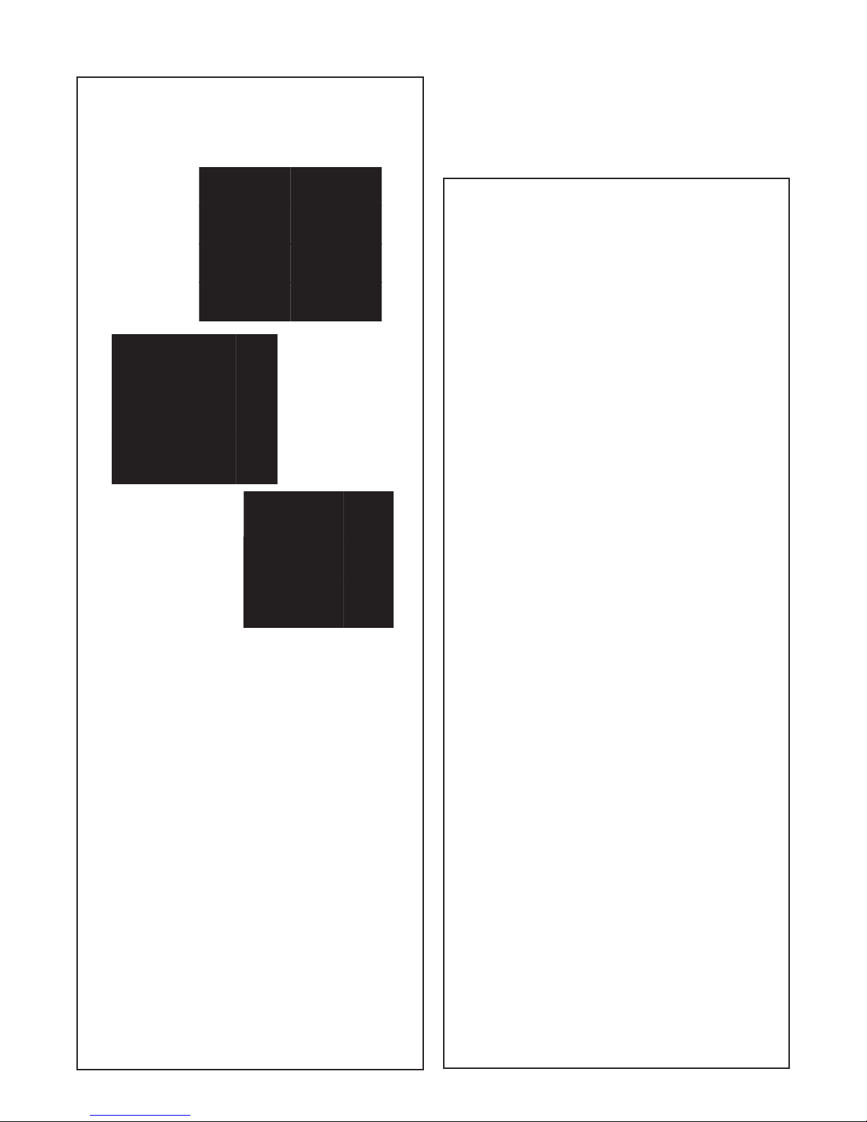
Model Nomenclature: for Indoor Split Series
321
YDS05
YDS = INDOOR TWO-STAGE PURON
SPLIT SYSTEM CONDENSING UNIT
YCS = INDOOR SPLIT SYSTEM
YCS
018
024
030
036
042
048
060
NOTE: Some options/configurations not availaible on all series. Please consult Engineering Guides for model specific options.
UNIT TYPE:
CONDENSING UNIT
SIZE:
YDS
026
038
049
064
AIRFLOW CONFIGURATION:
2
N = NONE
CONTROL:
YDS - C = CXM
YCS - L = CXM
86754
C06N
3C
HEAT EXCHANGER OPTIONS:
C = COPPER WATER COIL
D = COPPER WATER COIL W/HOT WATER GENERATOR
N = CUPRO-NICKEL WATER COIL
P = CUPRO-NICKEL WATER COIL W/HOT WATER GENERATOR
NOTE: Above model nomenclature is a general reference. Consult individual specifi cation catalogs
for detailed information.
1211109
0
1
PACKAGING:
1=SINGLE PACK,DOMESTIC
REVISION LEVEL:
0 = CURRENT REV IS ION
VOLTAGE:
3 = 208V, 230V/1PH/60Hz
Rev.: 08/15/05D
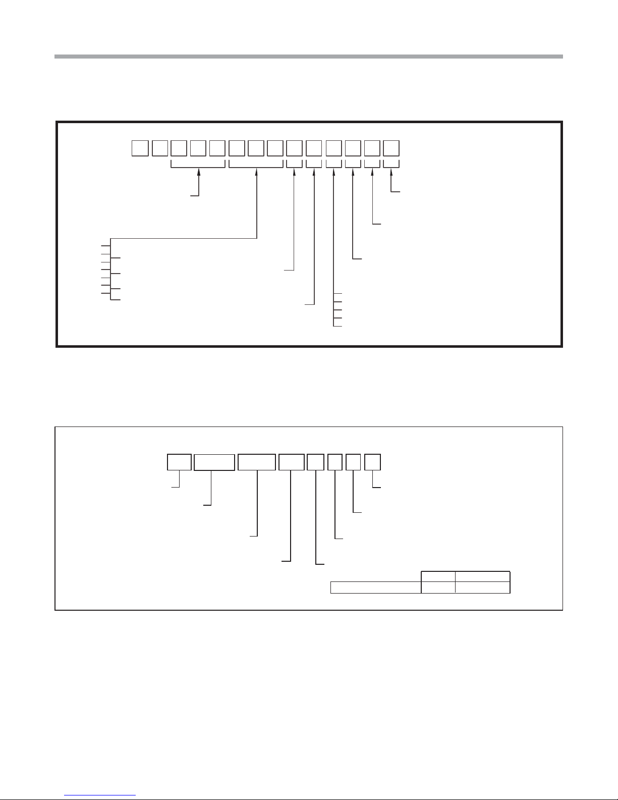
Model Nomenclature: for Outdoor Split Series
38 SS0 2 4 C 3 1 1
Prefix
WQS = Extended Range Ultra High
Efficiency Residential Outdoor Split
Series
018, 024, 030, 036, 042, 048, 060
1 2 3
WQS
Unit Size
4 5 6 7 8 9 10 11 12
Voltage
3 = 208-230/60/1
Standard
SS = Standard
Heat Exchanger Options
Standard
Packaging
1 = Single Pack, Domestic
Revision Level
1 = Current Revision
Copper Cupro-Nickel
CN
Carrier: Turn to the Experts
3

Residential Split - 60Hz R22 &R410A
Rev.: 5 June, 2008
Safety
Safety
Warnings, cautions and notices appear throughout this
manual. Read these items carefully before attempting any
installation, service or troubleshooting of the equipment.
DANGER: Indicates an immediate hazardous situation, which
if not avoided will result in death or serious injury. DANGER
labels on unit access panels must be observed.
WARNING: Indicates a potentially hazardous situation, which
if not avoided could result in death or serious injury.
CAUTION: Indicates a potentially hazardous situation or an
unsafe practice, which if not avoided could result in minor or
moderate injury or product or property damage.
NOTICE: Notifi cation of installation, operation or
maintenance information, which is important, but which is
not hazard-related.
WARNING!
WARNING! All refrigerant discharged from this unit must be
recovered WITHOUT EXCEPTION. Technicians must follow
industry accepted guidelines and all local, state, and federal
statutes for the recovery and disposal of refrigerants. If a
compressor is removed from this unit, refrigerant circuit oil will
remain in the compressor. To avoid leakage of compressor oil,
refrigerant lines of the compressor must be sealed after it is
removed.
CAUTION!
CAUTION!
these units as a source of heating or cooling during the
construction process. The mechanical components and
fi lters will quickly become clogged with construction dirt
and debris, which may cause system damage.
To avoid equipment damage, DO NOT use
WARNING!
WARNING! Verify refrigerant type before proceeding.
Units are shipped with R-22, R-407c and R-410A (Puron®)
refrigerants. The unit label will indicate which refrigerant
is provided. The Puron® Application and Service Manual
should be read and understood before attempting to service
refrigerant circuits with R-407c or R-410A.
WARNING!
WARNING! To avoid the release of refrigerant into the
atmosphere, the refrigerant circuit of this unit must be
serviced only by technicians who meet local, state, and
federal profi ciency requirements.
4
Water-Source Heating and Cooling Systems

Residential Split - 60Hz R22 &R410A
Rev.: 5 June, 2008
General Information
Inspection
Upon receipt of the equipment, carefully check the shipment
against the bill of lading. Make sure all units have been
received. Inspect the packaging of each unit, and inspect each
unit for damage. Insure that the carrier makes proper notation
of any shortages or damage on all copies of the freight bill and
completes a common carrier inspection report. Concealed
damage not discovered during unloading must be reported
to the carrier within 15 days of receipt of shipment. If not fi led
within 15 days, the freight company can deny the claim without
recourse. Note: It is the responsibility of the purchaser to fi le
all necessary claims with the carrier. Notify your equipment
supplier of all damage within fi fteen (15) days of shipment.
Storage
Equipment should be stored in its original packaging in a
clean, dry area. Store units in an upright position at all times.
Stack units a maximum of 3 units high.
Unit Protection
Cover units on the job site with either the original packaging
or an equivalent protective covering. Cap the open ends of
pipes stored on the job site. In areas where painting, plastering,
and/or spraying has not been completed, all due precautions
must be taken to avoid physical damage to the units and
contamination by foreign material. Physical damage and
contamination may prevent proper start-up and may result in
costly equipment clean-up.
5. Loosen compressor bolts on units equipped with
compressor spring vibration isolation until the
compressor rides freely on the springs. Remove shipping
restraints.
6. REMOVE COMPRESSOR SUPPORT PLATE 1/4”
SHIPPING BOLTS (2 on each side) TO MAXIMIZE
VIBRATION AND SOUND ATTENUATION (R22 indoor
units only).
7. Locate and verify any hot water generator (HWG) or
other accessory kit located in the compressor section.
CAUTION!
CAUTION! DO NOT store or install units in corrosive
environments or in locations subject to temperature or
humidity extremes (e.g., attics, garages, rooftops, etc.).
Corrosive conditions and high temperature or humidity can
signifi cantly reduce performance, reliability, and service life.
Always move and store units in an upright position. Tilting
units on their sides may cause equipment damage.
NOTICE! Failure to remove shipping brackets from springmounted compressors will cause excessive noise, and could
cause component failure due to added vibration.
CAUTION!
Examine all pipes, fi ttings, and valves before installing any of
the system components. Remove any dirt or debris found in
or on these components.
Pre-Installation
Installation, Operation, and Maintenance instructions
are provided with each unit. Horizontal equipment is
designed for installation above false ceiling or in a ceiling
plenum. Other unit confi gurations are typically installed
in a mechanical room. The installation site chosen should
include adequate service clearance around the unit. Before
unit start-up, read all manuals and become familiar with the
unit and its operation. Thoroughly check the system before
operation.
Prepare units for installation as follows:
1. Compare the electrical data on the unit nameplate with
ordering and shipping information to verify that the
correct unit has been shipped.
2. Keep the cabinet covered with the original packaging
until installation is complete and all plastering, painting,
etc. is fi nished.
3. Verify refrigerant tubing is free of kinks or dents and that
it does not touch other unit components.
4. Inspect all electrical connections. Connections must be
clean and tight at the terminals.
CAUTION! CUT HAZARD - Failure to follow this caution
may result in personal injury. Sheet metal parts may have
sharp edges or burrs. Use care and wear appropriate
protective clothing, safety glasses and gloves when
handling parts and servicing heat pumps.
Carrier: Turn to the Experts
5

Residential Split - 60Hz R22 &R410A
Rev.: 5 June, 2008
Equipment Selection
The installation of geothermal heat pump units and all
associated components, parts, and accessories which make
up the installation shall be in accordance with the regulations
of ALL authorities having jurisdiction and MUST conform to
all applicable codes. It is the responsibility of the installing
contractor to determine and comply with ALL applicable
codes and regulations.
General
Proper indoor coil selection is critical to system effi ciency.
Using an older-model coil can affect effi ciency and may
not provide the customer with rated or advertised EER
and COP. Coil design and technology have dramatically
improved operating effi ciency and capacity in the past 20
years. Homeowners using an older coil are not reaping these
cost savings and comfort benefi ts. NEVER MATCH AN R-22
INDOOR COIL WITH AN R-410A COMPRESSOR SECTION.
Newer indoor coils have a larger surface area, enhanced fi n
design, and grooved tubing. These features provide a larger
area for heat transfer, improving effi ciency and expanding
capacity. Typical older coils may only have one-third to onehalf the face area of these redesigned coils.
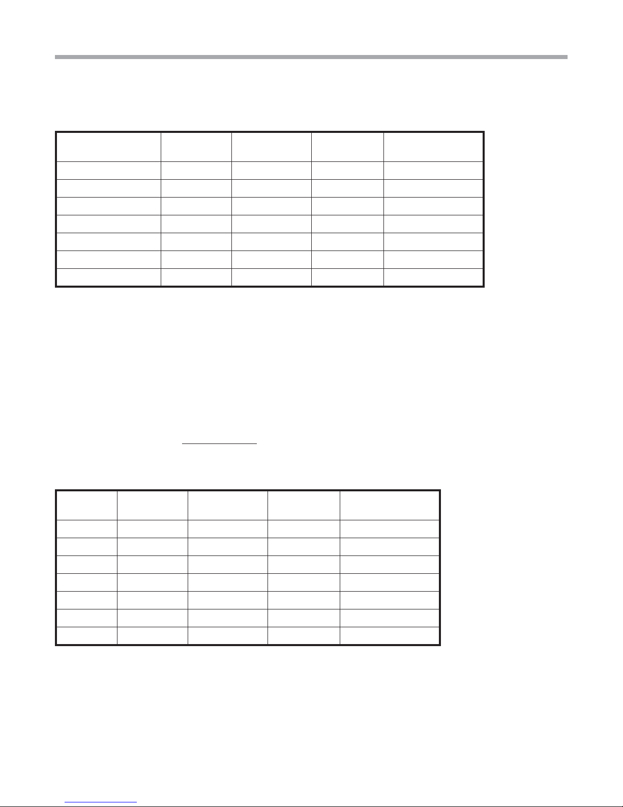
Table 1a: GT-PX Air Handler Matches for ARI Ratings
Indoor Coil Selection - GT-PX Split (50YDS)
Carrier Geothermal split system heat pumps are rated in
the ARI directory with a specifi c indoor coil match. GT-PX
Split (50YDS) models are rated with Carrier/Bryant FV4 or
FE4 series variable speed air handlers as shown in Table
1a. Other brands of air handlers may attain the same ARI
ratings providing that the specifi cations meet or exceed
those listed in Table 1a AND Table 1b. An ECM motor
and TXV is required. Cap tubes and fi xed orifi ces are not
acceptable. PSC fans may be used if matched to Table 1b,
but will not meet ARI ratings. If using PSC fan, compressor
section must be operated as a single stage unit (i.e. wired for
either 1st stage or 2nd stage). Without the ability to vary the
airfl ow, supply air temperatures may not be acceptable if the
compressor is allowed to change stages when used with a
PSC fan motor.
Compressor Section 026 038 049 064
Air Handler
Model FV4
003 005 006 006
Refrigerant R-410A
Metering Device TXV (required)
Air Coil
Type
Rows - Fins/in.
Face Area (sq. ft.)
Cabinet Confi gura-
Slope
3 - 14.5
3.46
A
3 - 14.5
5.93
Upfl ow/Downfl ow/Horizontal (Multipoise)
A
3 - 14.5
7.42
A
3 - 14.5
7.42
tion
ECM Settings for
ARI Ratings
(FV4 Fan Coil)
AC/HP size: 036
System Type:
Comfort AC/HP
CFM Adjust: Nom
AC/HP size: 036
System Type:
HP-Effi c AC/HP
CFM Adjust: High
AC/HP size: 048
System Type:
Comfort AC/HP
CFM Adjust: High
AC/HP size: 060
System Type:
Comfort AC/HP
CFM Adjust: High
Fan Motor Type - HP ECM - 1/2 ECM - 1/2 ECM - 3/4 ECM - 3/4
6
Water-Source Heating and Cooling Systems
Residential Split - 60Hz R22 &R410A
Table 1b: GT-PX Air Handler Characteristics for Brands other than Above Models
Rev.: 5 June, 2008
Equipment Selection
Model*
Nominal
Tons*
Evaporator
Temp (ºF)
CFM
Capacity
(MBtuh)**
026 - Part Load 1.5 50 530 19.2 - 22.4
026 - Full Load 2.0 52 880 24.2 - 28.2
038 - Part Load 2.5 51 700 25.2 - 29.2
038 - Full Load 3.0 50 1200 34.5 - 40.1
049 - Part Load 3.5 47 1000 34.3 - 39.9
049 - Full Load 4.0 48 1650 46.3 - 53.8
064 - Full Load 5.0 48 1850 54.5 - 63.3
* Nominal tons are at ARI/ISO 13256-1 GLHP conditions. Two-stage units may be operated in single-stage mode if desired, where smaller
capacity is required. For example, a model 026 may be used as a 1-1/2 ton unit if “locked” into 1st stage operation only. If PSC fan is used,
unit must be “locked” into either 1st or 2nd stage. An ECM fan is required for two-stage operation and for ARI ratings. Size air handler for
“Full Load” if operating in two-stage mode.
**When selecting an air handler based upon the above conditions, choose entering WB temperature of 67ºF. Use evaporator temperature,
CFM and capacity requirements as listed above. The air handler capacity must be at least at the minimum capacity shown in the table in
order for the ARI rating condition to be valid. See Figure 1 for an example selection.
Indoor Coil Selection - R-22 Units
Geothermal split system heat pumps with R-22 refrigerant
are rated in the ARI directory with a “generic” indoor
coil match and PSC fan. Selection of air handlers that
attain the published ARI ratings must meet or exceed the
specifi cations listed in Table 2. A TXV is required. Cap tubes
and fi xed orifi ces are not acceptable.
Table 2: R-22 Air Handler Characteristics
Model*
Nominal
Tons*
018 1.5 50 600 18.5 - 21.3
024 2.0 47 800 25.5 - 29.3
030 2.5 49 1000 31.5 - 36.2
036 3.0 48 1200 37.0 - 42.5
042 3.5 45 1400 42.2 - 48.5
048 4.0 46 1600 50.0 - 57.5
060 5.0 45 2000 58.0 - 66.7
* Nominal tons are at ARI/ISO 13256-1 GLHP conditions.
**When selecting an air handler based upon the above conditions, choose entering WB temperature of 67ºF. Use evaporator temperature,
CFM and capacity requirements as listed above. The air handler capacity must be at least at the minimum capacity shown in the table in
order for the ARI rating condition to be valid. See Figure 1 for an example selection.
Evaporator
Temp (ºF)
CFM
Capacity
(MBtuh)**
Carrier: Turn to the Experts
7

Residential Split - 60Hz R22 &R410A
Rev.: 5 June, 2008
Equipment Selection
Air Handler Selection Example
Figure 1 shows a typical performance table for a heat pump air
handler. Suppose the evaporator temperature required is 50ºF,
the capacity required is 35,000 Btuh and the airfl ow required
is 1,200 CFM. Each evaporator temperature listed in the table
shows three wet bulb temperatures. As recommended in the
table notes above, select the 67ºF WB column. At 1,200 CFM,
the model 003 capacity is 36 MBtuh, which is higher than the
minimum capacity required of 35,000 Btuh. In this example,
model 003 would be the appropriate match.
Figure 1: Selecting Air Handler
Utilizing the Existing Air Handler or Coil (R22 units only)
It is recommended that a new coil or air handler be installed
with any geothermal split system compressor section due
to the low initial cost of the additional equipment versus the
reliability and benefi t of new technology, increased reliability
and warranty. However, if the existing air handler must be used
(R22 systems only), the following conditions apply:
• If the existing coil currently uses an orifi ce, the orifi ce
must be removed and replaced with a TXV. If the coil
utilizes capillary tubes, it will not operate properly with the
geothermal split system and should be replaced.
• If life expectancy of indoor coil (and associated components
- fan, cabinet, etc.) is less than 7-10 years, indoor section
should be replaced.
8
Water-Source Heating and Cooling Systems

Residential Split - 60Hz R22 &R410A
Rev.: 5 June, 2008
Installation
NOTICE! Failure to remove shipping brackets from springmounted compressors will cause excessive noise, and could
cause component failure due to added vibration.
The installation of water source heat pump units and all
associated components, parts and accessories which make
up the installation shall be in accordance with the regulations
of ALL authorities having jurisdiction and MUST conform to
all applicable codes. It is the responsibility of the installing
contractor to determine and comply with ALL applicable
codes and regulations.
Removing Existing Condensing Unit (Where Applicable)
1. Pump down condensing unit. Close the liquid line
service valve of existing condensing unit and start
compressor to pump refrigerant back into compressor
section. Then, close suction service valve while
compressor is still running to trap refrigerant in outdoor
section. Immediately kill power to the condensing unit.
2. Disconnect power and low voltage and remove old
condensing unit. Cut or unbraze line set from unit.
Remove condensing unit.
3. If condensing unit is not operational or will not pump
down, refrigerant should be recovered using appropriate
equipment.
4. Replace line set, especially if upgrading system from R22 to R-410A refrigerant. If line set cannot be replaced,
it must be thoroughly fl ushed before installing new
compressor section. R-410A compressors use POE
oil instead of mineral oil (R-22 systems). Mineral oil is
not compatible with POE oil, and could cause system
damage if not completely fl ushed from the line set.
“Indoor” Compressor Section Location
Both “indoor” and “outdoor” versions of the geothermal split
system compressor section are available. “Indoor” version
is not designed for outdoor installation. Locate the unit
in an INDOOR area that allows enough space for service
personnel to perform typical maintenance or repairs without
removing unit. Units are typically installed in a mechanical
room or closet. Never install units in areas subject to freezing
or where humidity levels could cause cabinet condensation
(such as unconditioned spaces subject to 100% outside air).
Consideration should be given to access for easy removal
of service access panels. Provide suffi cient room to make
water, electrical, and line set connections.
2. Provide adequate clearance for maintenance and
service. Do not block access panels with piping, conduit
or other materials.
3. Provide access for servicing the compressor and coils
without removing the unit.
4. Provide an unobstructed path to the unit within the
closet or mechanical room. Space should be suffi cient to
allow removal of the unit, if necessary.
5.
In limited side access installations, pre-removal of the
control box side mounting screws will allow control box
removal for future servicing (R22 units only).
6. Provide access to water valves and fi ttings and
screwdriver access to the unit side panels and all
electrical connections.
“Outdoor” Compressor Section Loacation
Locate the unit in an outdoor area that allows easy loop
and lineset access and also has enough space for service
personnel to perform typical maintenance or repairs. The
“outdoor” compressor section is usually installed on a
condensor pad directly outside the lineset access into the
building. The service valve side can be located toward
the building, keeping the loop access end away from the
building. Conform to the following guidelines when selecting
unit location:
1. Provide adequate access for loop trench excavation.
2.
Locate unit directly outside lineset penetration if possible.
Utilize existing condensor pad where possible.
3. Provide access for servicing and maintenance.
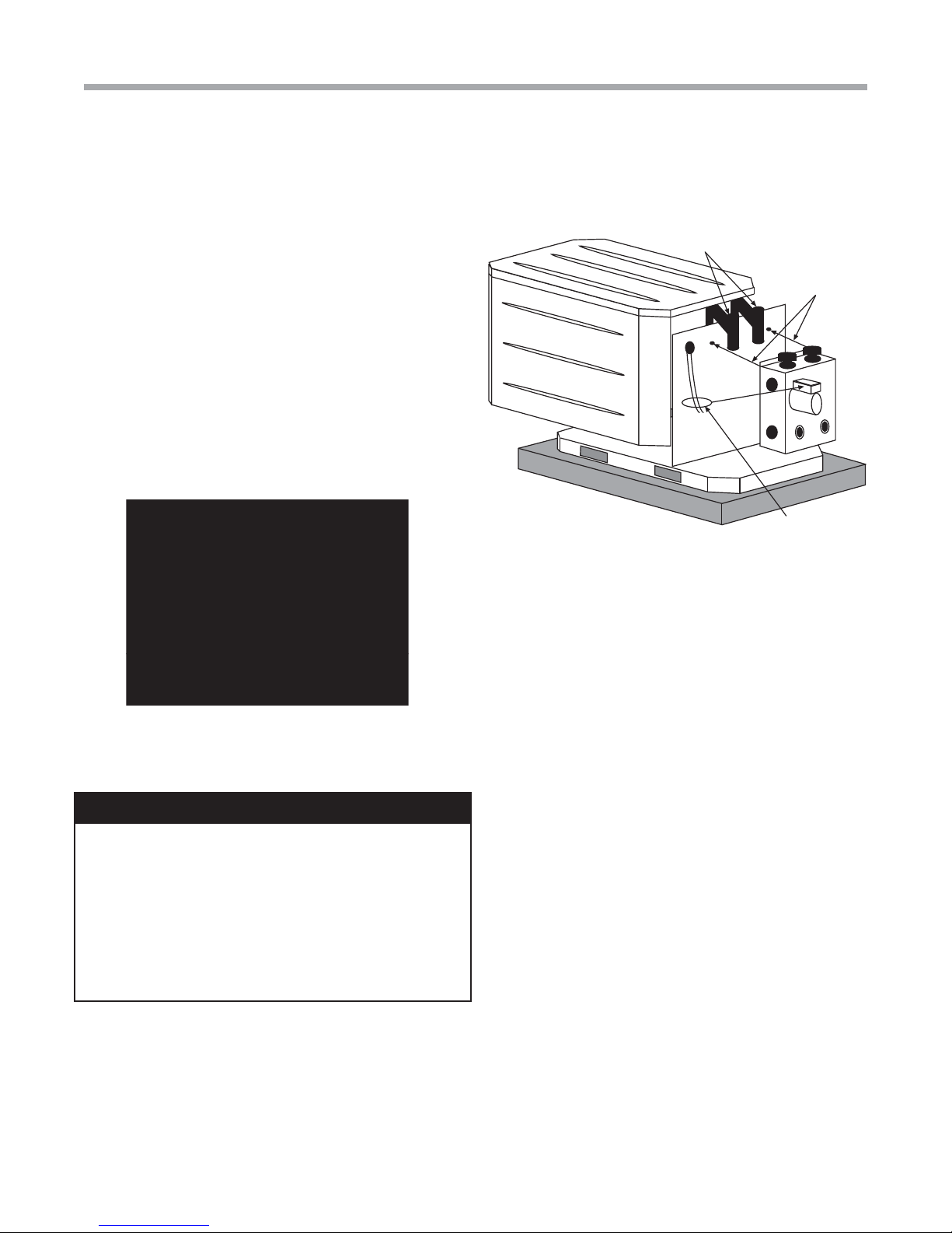
“Outdoor” compressor section may be mounted on a
vibration isolation pad with loop access hole as shown in
Figure 3. When mounting on an existing concrete condenser
pad, 3” [76mm] holes should be bored through the pad to
accomodate the pipe (1-1/4” - 32mm) and insulation (1/2”
[13mm] wall thickness). Figure 3 illustrates location and
dimensions of the holes required.
Air Handler Installation
This manual specifi cally addresses the compressor section
of the system. Air handler location and installation should
be according to the instructions provided with the air
handling unit.
Any access panel screws that would be diffi cult to remove
after the unit is installed should be removed prior to setting
the unit. Refer to Figure 2 for an illustration of a typical
installation. Refer to “Physical Dimensions” section for
dimensional data.
selecting unit location:
Install the unit on a piece of rubber, neoprene or other
1.
mounting pad material for sound isolation. The pad should
be at least 3/8” [10mm] to 1/2” [13mm] in thickness.
Extend the pad beyond all four edges of the unit.
Conform to the following guidelines when
Carrier: Turn to the Experts
9

Residential Split - 60Hz R22 &R410A
Air Pad with
access hole
Existing Pad larger than 22" x 33" [54 x 84cm]
Bottom view
of Unit
22" x 33"
[56 x 84cm]
Flow
Controller
8.00"
25"
[63.5cm]
Drill 3" [76mm] holes for
clearance of 1-1/4" [32mm] pipe
with 1/2" [13mm] wall insulation
5.5"
[14.0cm]
8.25"
[21.0cm]
Gasket
Swivel Nut
Stainless steel
snap ring
Brass Adaptor
Hand Tighten
Only!
Do Not
Overtighten!
Rev.: 5 June, 2008
Installation
Figure 2: 50YDS/GT-GS Installation
Figure 3: GT-S Installation
External Flow Controller Mounting
The Flow Controller can be mounted beside the unit as
shown in Figure 7. Review the Flow Controller installation
manual for more details.
Water Connections-Residential (Distributor) Models
Residential models utilize swivel piping fi ttings for water
connections that are rated for 450 psi (3101 kPa) operating
pressure. The connections have a rubber gasket seal
similar to a garden hose gasket, which when mated to the
10
fl ush end of most 1” threaded male pipe fi ttings provides
a leak-free seal without the need for thread sealing tape or
joint compound. Insure that the rubber seal is in the swivel
connector prior to attempting any connection (rubber seals
are shipped attached to the swivel connector). DO NOT
OVER TIGHTEN or leaks may occur.
Water-Source Heating and Cooling Systems
The female locking ring is threaded onto the pipe threads
which holds the male pipe end against the rubber gasket,
and seals the joint. HAND TIGHTEN ONLY! DO NOT
OVERTIGHTEN!
Figure 4: Water Connections (Indoor Compressor Section)
Residential Split - 60Hz R22 &R410A
Rev.: 5 June, 2008
Installation
Internal Flow Controller Mounting “Outdoor” Compressor Section Only
The Flow Controller can be mounted in the “outdoor”
compressor section directly inside the cabinet as shown in
Figure 5. Remove the water legs from the outdoor unit at the
union fi ttings. Attached the AFC4T 1” MPT x o-ring fi ttings
to the removed water legs. Carefully attached the Flow
Controller to the loop piping and mount to the outdoor unit
using the mounting lugs attached to the unit. Insert the water
legs into the Flow Controller using the o-ring fi ttings. Re-
connect the water leg unions.
NOTICE! Opening in the bottom of the unit for loop piping
must be sealed to prevent rodents from getting into the
cabinet and damaging control wiring. Spray type foam may
be used to seal the opening(s).
Figure 6: AFC4T Connector
Figure 5: Water Connections (Outdoor Compressor Section)
1” IPT Water Connections
Mount Flow Controller
on studs provided
Wire pump power
using provided wires
for L1 and L2
GROUND-LOOP HEAT PUMP APPLICATIONS
CAUTION!
CAUTION! The following instructions represent industry
accepted installation practices for closed loop earth
coupled heat pump systems. Instructions are provided
to assist the contractor in installing trouble free ground
loops. These instructions are recommendations only.
State/provincial and local codes MUST be followed and
installation MUST conform to ALL applicable codes. It is
the responsibility of the installing contractor to determine
and comply with ALL applicable codes and regulations.
Pre-Installation
Prior to installation, locate and mark all existing underground
utilities, piping, etc. Install loops for new construction before
sidewalks, patios, driveways, and other construction has
begun. During construction, accurately mark all ground loop
piping on the plot plan as an aid in avoiding potential future
damage to the installation.
Piping Installation
The typical closed loop ground source system is shown in
Figures 7 and 8. All earth loop piping materials should be
limited to polyethylene fusion only for in-ground sections of
the loop. Galvanized or steel fi ttings should not be used at
any time due to their tendency to corrode. All plastic to metal
threaded fi ttings should be avoided due to their potential to
leak in earth coupled applications. A fl anged fi tting should
be substituted. P/T plugs should be used so that fl ow
can be measured using the pressure drop of the unit heat
exchanger.
Carrier: Turn to the Experts
11

Residential Split - 60Hz R22 &R410A
Rev.: 5 June, 2008
Ground-Loop Heat Pump Applications
Earth loop temperatures can range between 25 and
110°F [-4 to 43°C]. Flow rates between 2.25 and 3 gpm
per ton [2.41 to 3.23 l/m per kW] of cooling capacity is
recommended in these applications.
Test individual horizontal loop circuits before backfi lling.
Test vertical U-bends and pond loop assemblies prior to
installation. Pressures of at least 100 psi [689 kPa] should be
used when testing. Do not exceed the pipe pressure rating.
Test entire system when all loops are assembled.
Flushing the Earth Loop
Once piping is completed between the unit, Flow Controller
and the ground loop (Figures 7 and 8), the loop is ready for
fi nal purging and charging. A fl ush cart with at least a 1.5 hp
[1.1 kW] pump is required to achieve enough fl uid velocity
in the loop piping system to purge air and dirt particles. An
antifreeze solution is used in most areas to prevent freezing.
All air and debris must be removed from the earth loop
piping before operation. Flush the loop with a high volume
of water at a minimum velocity of 2 fps (0.6 m/s) in all piping.
The steps below must be followed for proper fl ushing.
1. Fill loop with water from a garden hose through the fl ush
cart before using the fl ush cart pump to insure an even
fi ll.
2. Once full, the fl ushing process can begin. Do not allow
the water level in the fl ush cart tank to drop below the
pump inlet line to avoid air being pumped back out to
the earth loop.
3. Try to maintain a fl uid level in the tank above the return
tee so that air cannot be continuously mixed back into
the fl uid. Surges of 50 psi (345 kPa) can be used to help
purge air pockets by simply shutting off the return valve
going into the fl ush cart reservoir. This “dead heads”
the pump to 50 psi (345 kPa). To purge, dead head the
pump until maximum pumping pressure is reached.
Open the return valve and a pressure surge will be sent
through the loop to help purge air pockets from the
piping system.
4. Notice the drop in fl uid level in the fl ush cart tank when
the return valve is shut off. If air is adequately purged
from the system, the level will drop only 1-2 inches (2.5
- 5 cm) in a 10” (25 cm) diameter PVC fl ush tank (about a
half gallon [2.3 liters]), since liquids are incompressible. If
the level drops more than this, fl ushing should continue
since air is still being compressed in the loop fl uid.
Perform the “dead head” procedure a number of times.
Note: This fl uid level drop is your only indication of air in
the loop.
Antifreeze may be added before, during or after the fl ushing
procedure. However, depending upon which time is chosen,
antifreeze could be wasted when emptying the fl ush cart
tank. See antifreeze section for more details.
Loop static pressure will fl uctuate with the seasons.
Pressures will be higher in the winter months than during
the cooling season. This fl uctuation is normal and should
be considered when charging the system initially. Run the
unit in either heating or cooling for a number of minutes to
condition the loop to a homogenous temperature. This is
a good time for tool cleanup, piping insulation, etc. Then,
perform fi nal fl ush and pressurize the loop to a static
pressure of 50-75 psi [345-517 kPa] (winter) or 35-40 psi
[241-276 kPa] (summer). After pressurization, be sure to
loosen the plug at the end of the Grundfos loop pump
motor(s) to allow trapped air to be discharged and to insure
the motor housing has been fl ooded. This is not required
for Taco circulators. Insure that the Flow Controller provides
adequate fl ow through the unit by checking pressure drop
across the heat exchanger and compare to the pressure
drop tables at the back of the manual.
Antifreeze
In areas where minimum entering loop temperatures drop
below 40°F [5°C] or where piping will be routed through
areas subject to freezing, antifreeze is required. Alcohols
and glycols are commonly used as antifreeze; however your
local sales manager should be consulted for the antifreeze
best suited to your area. Freeze protection should be
maintained to 15°F [9°C] below the lowest expected
entering loop temperature. For example, if 30°F [-1°C] is
the minimum expected entering loop temperature, the
leaving loop temperature would be 25 to 22°F [-4 to -6°C]
and freeze protection should be at 15°F [-10°C]. Calculation
is as follows:
30°F - 15°F = 15°F [-1°C - 9°C = -10°C].
All alcohols should be premixed and pumped from a
reservoir outside of the building when possible or introduced
under the water level to prevent fumes. Calculate the
total volume of fl uid in the piping system. Then use the
percentage by volume shown in Table 2 for the amount
of antifreeze needed. Antifreeze concentration should be
checked from a well mixed sample using a hydrometer to
measure specifi c gravity.
Low Water Temperature Cutout Setting
CXM or DXM Control
When antifreeze is selected, the FP1 jumper (JW3) should
be clipped to select the low temperature (antifreeze 13°F
[-10.6°C]) set point and avoid nuisance faults (see “Low
Water Temperature Cutout Selection” in this manual). NOTE:
Low water temperature operation requires extended range
equipment.
12
Water-Source Heating and Cooling Systems

Residential Split - 60Hz R22 &R410A
Rev.: 5 June, 2008
Ground-Loop Heat Pump Applications
Table 1: Approximate Fluid Volume (U.S. gal. [L]) per
100' of Pipe
Fluid Volume (gal [liters] per 100’ [30 meters) Pipe)
Pipe Size Volume (gal) [liters]
1” 4.1 [15.3]
Copper
Rubber Hose 1” 3.9 [14.6]
Polyethylene
Unit Heat Exchanger Typical 1.0 [3.8]
Flush Cart Tank
1.25” 6.4 [23.8]
2.5” 9.2 [34.3]
3/4” IPS SDR11 2.8 [10.4]
1” iPS SDR11 4.5 [16.7]
1.25” IPS SDR11 8.0 [29.8]
1.5” IPS SDR11 10.9 [40.7]
2” IPS SDR11 18.0 [67.0]
1.25” IPS SCH40 8.3 [30.9]
1.5” IPS SCH40 10.9 [40.7]
2” IPS SCH40 17.0 [63.4]
10” Dia x 3ft tall
[254mm x 91.4cm tall]
10 [37.9]
Figure 7: Loop Connection (Indoor
Compressor Section)
Unit Power
Disconnect
AH & Thermostat
Wiring
Air Pad or
Extruded
polystyrene
insulation board
Flow
Controller
Insulated
Hose Kit
To Loop
P/T Plugs
Figure 8: Loop Connection (Outdoor Compressor Section)
P/T Ports
Flow Controller
Insulate all piping with 1/2"
[13mm] closed cell insulation
Backfill carefully to avoid
stress on piping and flow
controller connection
Air Pad with access hole
Header Pit
Table 2: Antifreeze Percentages by Volume
Type
Methanol
100% USP food grade Propylene Glycol
Ethanol*
10°F [-12.2°C] 15°F [-9.4°C] 20°F [-6.7°C] 25°F [-3.9°C]
25%
38%
29%
Minimum Temperature for Low Temperature Protection
NOTICE! Cabinet opening around loop piping (outdoor
compressor section) must be sealed to prevent entry of
rodents that could potentially damage unit wiring by chewing
on the insulation.
NOTICE! Outdoor compressor section may not be tilted
more than 5 degrees from level. Damage to the compressor
or stress on the loop piping could result if unit is tilted. A
concrete pad, anchor posts and/or soil compaction may be
required to avoid tilting as ground settles.
21%
25%
25%
16%
22%
20%
10%
15%
14%
* Must not be denatured with any petroleum based product
Carrier: Turn to the Experts
13

Residential Split - 60Hz R22 &R410A
Rev.: 5 June, 2008
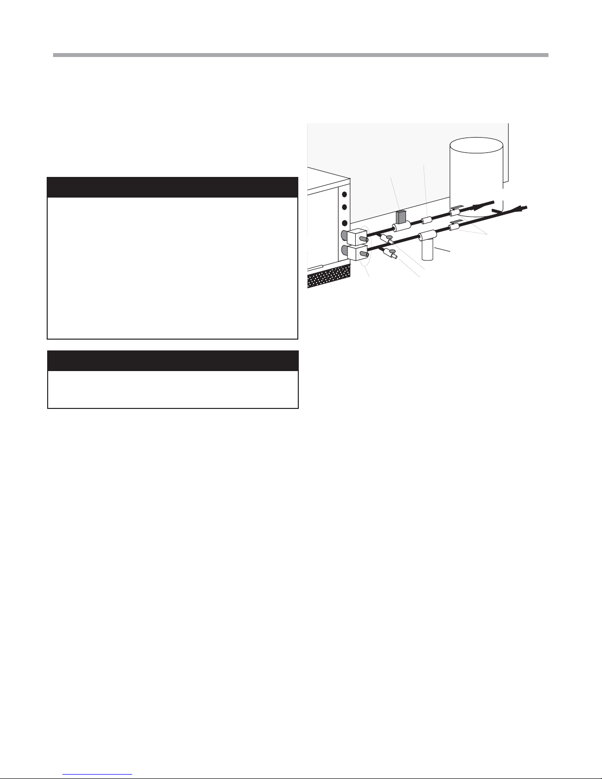
Ground-Water Heat Pump Applications “Indoor” Compressor Section Only
Open Loop - Ground Water Systems
(“Indoor” Compressor Section Only)
The “outdoor” version of the compressor section may not
be used with open loop systems due to potential freezing of
water piping. Typical open loop piping is shown in Figure 9.
Shut off valves should be included for ease of servicing. Boiler
drains or other valves should be “tee’d” into the lines to allow
acid fl ushing of the heat exchanger. Shut off valves should
be positioned to allow fl ow through the coax via the boiler
drains without allowing fl ow into the piping system. P/T plugs
should be used so that pressure drop and temperature can be
measured. Piping materials should be limited to copper or PVC
SCH80. Note: Due to the pressure and temperature extremes,
PVC SCH40 is not recommended.
Water quantity should be plentiful and of good quality.
Consult Table 3 for water quality guidelines. The unit can
be ordered with either a copper or cupro-nickel water
heat exchanger. Consult Table 3 for recommendations.
Copper is recommended for closed loop systems and open
loop ground water systems that are not high in mineral
content or corrosiveness. In conditions anticipating heavy
scale formation or in brackish water, a cupro-nickel heat
exchanger is recommended. In ground water situations
where scaling could be heavy or where biological growth
such as iron bacteria will be present, an open loop system
is not recommended. Heat exchanger coils may over time
lose heat exchange capabilities due to build up of mineral
deposits. Heat exchangers must only be serviced by a
qualifi ed technician, as acid and special pumping equipment
is required. Desuperheater coils can likewise become scaled
and possibly plugged. In areas with extremely hard water,
the owner should be informed that the heat exchanger
may require occasional acid fl ushing. In some cases, the
desuperheater option should not be recommended due to
hard water conditions and additional maintenance required.
Water Quality Standards
Table 3 should be consulted for water quality requirements.
Scaling potential should be assessed using the pH/Calcium
hardness method. If the pH <7.5 and the Calcium hardness
is less than 100 ppm, scaling potential is low. If this method
yields numbers out of range of those listed, the Ryznar
Stability and Langelier Saturation indecies should be
calculated. Use the appropriate scaling surface temperature
for the application, 150°F [66°C] for direct use (well water/
open loop) and DHW (desuperheater); 90°F [32°F] for
indirect use. A monitoring plan should be implemented in
these probable scaling situations. Other water quality issues
such as iron fouling, corrosion prevention and erosion and
clogging should be referenced in Table 3.
Expansion Tank and Pump
Use a closed, bladder-type expansion tank to minimize
mineral formation due to air exposure. The expansion tank
should be sized to provide at least one minute continuous
run time of the pump using its drawdown capacity rating to
prevent pump short cycling. Discharge water from the unit
is not contaminated in any manner and can be disposed
of in various ways, depending on local building codes (e.g.
recharge well, storm sewer, drain fi eld, adjacent stream
or pond, etc.). Most local codes forbid the use of sanitary
sewer for disposal. Consult your local building and zoning
department to assure compliance in your area.
The pump should be sized to handle the home’s domestic
water load (typically 5-9 gpm [23-41 l/m]) plus the fl ow rate
required for the heat pump. Pump sizing and expansion
tank must be chosen as complimentary items. For example,
an expansion tank that is too small can causing premature
pump failure due to short cycling. Variable speed pumping
applications should be considered for the inherent energy
savings and smaller expansion tank requirements.
Water Control Valve
Note the placement of the water control valve in fi gure 9.
Always maintain water pressure in the heat exchanger by
placing the water control valve(s) on the discharge line
to prevent mineral precipitation during the off-cycle. Pilot
operated slow closing valves are recommended to reduce
water hammer. If water hammer persists, a mini-expansion
tank can be mounted on the piping to help absorb the
excess hammer shock. Insure that the total ‘VA’ draw of the
valve can be supplied by the unit transformer. For instance,
a slow closing valve can draw up to 35VA. This can overload
smaller 40 or 50 VA transformers depending on the other
controls in the circuit. A typical pilot operated solenoid valve
draws approximately 15VA (see Figure 24). Note the special
wiring diagrams for slow closing valves (Figures 25 & 26).
Flow Regulation
Flow regulation can be accomplished by two methods. One
method of fl ow regulation involves simply adjusting the ball
valve or water control valve on the discharge line. Measure
the pressure drop through the unit heat exchanger, and
determine fl ow rate from Tables 11a through 11b. Since
the pressure is constantly varying, two pressure gauges
may be needed. Adjust the valve until the desired fl ow of
1.5 to 2 gpm per ton [2.0 to 2.6 l/m per kW] is achieved. A
second method of fl ow control requires a fl ow control device
mounted on the outlet of the water control valve. The device
is typically a brass fi tting with an orifi ce of rubber or plastic
material that is designed to allow a specifi ed fl ow rate. On
occasion, fl ow control devices may produce velocity noise
that can be reduced by applying some back pressure from
the ball valve located on the discharge line. Slightly closing
the valve will spread the pressure drop over both devices,
lessening the velocity noise. NOTE: When EWT is below
50°F [10°C], a minimum of 2 gpm per ton (2.6 l/m per kW)
is required.
14
Water-Source Heating and Cooling Systems
Residential Split - 60Hz R22 &R410A
Rev.: 5 June, 2008
Ground-Water Heat Pump Applications
Water Coil Low Temperature Limit Setting
For all open loop systems the 30°F [-1.1°C] FP1 setting
(factory setting-water) should be used to avoid freeze damage
to the unit. See “Low Water Temperature Cutout Selection” in
this manual for details on the low limit setting.
CAUTION!
CAUTION! Many units installed with a factory or fi eld
supplied manual or electric shut-off valve. DAMAGE WILL
OCCUR if shut-off valve is closed during unit operation. A
high pressure switch must be installed on the heat pump
side of any fi eld provided shut-off valves and connected to
the heat pump controls in series with the built-in refrigerant
circuit high pressure switch to disable compressor operation
if water pressure exceeds pressure switch setting. The fi eld
installed high pressure switch shall have a cut-out pressure
of 300 psig and a cut-in pressure of 250 psig. This pressure
switch can be ordered from Carrier Geothermal with a 1/4”
internal fl are connection as part number 39B0005N02.
CAUTION!
CAUTION! Refrigerant pressure activated water regulating
valves should never be used with Carrier Geothermal
equipment.
Figure 9: Water Well Connections
Wate r
Control
Va l v e
P/T Plugs
Flow
Regulator
Boiler
Drains
Pressure
Ta n k
Water Out
Water In
Shut-Off
Valve
Optional
Filter
Carrier: Turn to the Experts
15
 Loading...