

Carrier GR-45, GR-60 Operation And Service

Bus Air
Conditioning
Equipment
Models
GR--45
GR--60
(N.A.O.)
T--295
AC Pressure Sensor
OPERATION AND
SERVICE MANUAL
BUS
AIR CONDITIONING
UNIT
Models
Carrier Refrigeration Operations
Carrier Transicold Division, Carrier Corporation, P.O. Box 4805, Syracuse, N.Y. 13221 U. S. A.
Carrier Corporation 2000 D Printed in U. S. A. 0300
GR--45
GR--60
(N.A.O.)
AC Pressure Sensor

SAFETY SUMMARY
GENERAL SAFETY NOTICES
The following general safety notices supplement the specific warnings and cautions appearing elsewhere in this
manual. They are recommended precautions that must be understood and applied during operation and maintenance
of the equipment covered herein. A listing of the specific warnings and cautions appearing elsewhere in the manual
follows the general safety notices.
FIRST AID
Aninjury,no matterhow slight, should nevergo unattended.Alwaysobtain firstaidormedicalattentionimmediately.
OPERATING PRECAUTIONS
Always wear safety glasses.
Keep hands, clothing and tools clear of the evaporator and condenser fans.
No work should be performed on the unit until all circuit breakers and start-stop switches are placed in the OFF
position, and power supply is disconnected.
Always work in pairs. Never work on the equipment alone.
In case of severe vibration or unusual noise, stop t he unit and investigate.
MAINTENANCE PRECAUTIONS
Beware of unannounced starting of the evaporator and condenser fans. Do not open the unit cover before turning
power off.
Besurepoweristurnedoffbeforeworkingon motors, controllers, solenoid valves and electricalcontrols. Tagcircuit
breaker and power supply to prevent accidental energizing of circuit.
Do not bypass any electrical safety devices, e.g. bridging an overload, or using any sort of jumper wires. Problems
with the system should be diagnosed, and any necessary repairs performed, by qualified service personnel.
Whenperforming any arcweldingon the unit, disconnect allwireharnessconnectors from the modulesin the control
box. Do not remove wire harnessfrom the modules unless you aregrounded to the unit frame with a static-safewrist
strap.
In case of electrical fire, open circuit switch and extinguish with CO
SPECIFIC WARNINGS AND CAUTIONS
(never use water).
2
WARNING
DO NOT USE A NITROGEN CYLINDER WITHOUT A PRESSURE REGULATOR
WARNING
DO NOT USEOXYGEN IN OR NEAR A REFRIGERATION SYSTEM AS AN EXPLOSIONMAY
OCCUR.
WARNING
THE FILTER-DRIER MAY CONTAIN LIQUID REFRIGERANT. SLOWLY LOOSEN THE
FLARE NUTS AND AVOID CONTACT WITH EXPOSED SKIN OR EYES.
CAUTION
Donot under anycircumstancesattempt toservicethemicroprocessor. should aproblem developwith
the microprocessor, replace it.
CAUTION
If unit was recently operated, be careful of remaining hot coolant in the hoses when disassembling.
Safety-1
AC Pressure Sensor
T--295

TABLE OF CONTENTS
PARAGRAPH NUMBER Page
SAFETY SUMMARY Safety-1.....................................................................
DESCRIPTION 1-1...............................................................................
1.1 INTRODUCTION 1-1..............................................................
1.2 GENERAL DESCRIPTION 1-2......................................................
1.2.1 Apex Unit 1-2..................................................................
1.2.2 Condensing S ection 1-2..........................................................
1.2.3 Evaporator Section 1-3...........................................................
1.2.4 Compressor Assembly 1-4........................................................
1.2.5 Fresh Air System 1-4............................................................
1.2.6 System Operating Controls And Components 1-4.....................................
1.3 REFRIGERATION SYSTEM COMPONENT SPECIFICATIONS 1-5........................
1.4 ELECTRICAL SPECIFICATIONS -- MOTORS 1-5......................................
1.5 ELECTRICAL SPECIFICATIONS -- SENSORS AND TRANSDUCERS 1-5..................
1.6 SAFETY DEVICES 1-5.............................................................
1.7 AIR FLOW 1-6....................................................................
1.8 AIR CONDITIONING REFRIGERATION CYCLE 1-6...................................
1.9 HEATING CYCLE 1-8.............................................................
1.10 RELAY BOARD 1-9...............................................................
1.10.1 Permanent Magnet Motors with 2 speed switching from series to parallel
connection (Option 1) 1-9........................................................
1.10.2 Electronically Communtated DC Motors with 2--speed Evaporator Input Signal (Option 2) 1-11.
1.11 LOGIC BOARD 1-12................................................................
1.12 CONTROL PANEL (Diagnostic Module) 1-13............................................
OPERATION 2-1.................................................................................
2.1 STARTING, STOPPING AND OPERATING INSTRUCTIONS 2-1..........................
2.1.1 Power to Logic Board 2-1........................................................
2.1.2 Starting 2-1....................................................................
2.1.3 Self-Test and Diagnostics (Check for Errors and/or Alarms) 2-1..........................
2.1.4 Stopping 2-1...................................................................
2.2 PRE--TRIP INSPECTION 2-1........................................................
2.3 MODES OF OPERATION 2-3.......................................................
2.3.1 Temperature Control 2-3.........................................................
2.3.2 Cooling Mode 2-3..............................................................
2.3.3 Heating Mode 2-3..............................................................
2.3.4 Boost Pump 2-3................................................................
2.3.5 Vent Mode 2-3.................................................................
2.3.6 Fresh Air System 2-3............................................................
2.3.7 Compressor Unloader Control 2-3..................................................
2.3.8 Evaporator Fan Speed Selection 2-4................................................
2.3.9 Condenser Fan Control 2-4.......................................................
2.3.10 Compressor Clutch Control 2-4....................................................
i T--295

TABLE OF CONTENTS (Continued)
PARAGRAPH NUMBER Page
2.3.11 Alarm Description 2-4...........................................................
2.3.12 Hour Meters 2-4................................................................
2.4 MICROPROCESSOR DIAGNOSTICS 2-4..........................................
2.4.1 Connecting 2-4.................................................................
2.4.2 Control 2-5....................................................................
2.4.3 Diagnostic Mode 2-5............................................................
2.4.4 System Parameters 2-5...........................................................
2.4.5 Test Mode 2-5.................................................................
TROUBLESHOOTING 3-1.........................................................................
3.1 SELF DIAGNOSTICS 3-1...........................................................
3.2 SYSTEM ALARMS 3-1............................................................
3.2.1 Alarm Codes 3-1...............................................................
3.2.2 Activation 3-1.................................................................
3.2.3 Alarm Queue 3-1...............................................................
3.2.4 Alarm Clear 3-1................................................................
3.3 TROUBLESHOOTING 3-1..........................................................
3.3.1 System Will Not Cool 3-4........................................................
3.3.2 System R uns But Has Insufficient C ooling 3-4........................................
3.3.3 Abnormal Pressures 3-4..........................................................
3.3.4 Abnormal Noise Or Vibrations 3-4.................................................
3.3.5 Control System Malfunction 3-5...................................................
3.3.6 No Evaporator Air Flow Or Restricted Air Flow 3-5...................................
3.3.7 Expansion Valve Malfunction 3-5..................................................
3.3.8 Heating Malfunction 3-5.........................................................
SERVICE 4-1....................................................................................
4.1 MAINTENANCE SCHEDULE 4-1....................................................
4.2 OPENING TOP COVER 4-1.........................................................
4.3 SUCTION AND DISCHARGE SERVICE VALVES 4-1...................................
4.4 INSTALLING MANIFOLD GAUGE SET 4-2...........................................
4.5 PUMPING THE SYSTEM DOWN OR REMOVING THE REFRIGERANT CHARGE 4-2.......
4.5.1 System Pump Down For Low Side Repair 4-2........................................
4.5.2 Refrigerant Removal From An Inoperative Compressor. 4-3.............................
4.5.3 Pump Down An Operable Compressor For Repair 4-3..................................
4.5.4. Removing Entire System Charge 4-4................................................
4.6 REFRIGERANT LEAK CHECK 4-4..................................................
4.7 EVACUATION AND DEHYDRATION 4-4.............................................
4.7.1 General 4-4....................................................................
4.7.2 Preparation 4-4.................................................................
4.7.3 Procedure for Evacuation and Dehydrating System 4-4.................................
T--295
ii

TABLE OF CONTENTS (Continued)
PARAGRAPH NUMBER Page
4.8 ADDING REFRIGERANT TO SYSTEM 4-5...........................................
4.8.1 Checking Refrigerant Charge 4-5..................................................
4.8.2 Adding Full Charge 4-5..........................................................
4.8.3 Adding Partial Charge 4-5........................................................
4.9 CHECKING FOR NONCONDENSIBLES 4-5...........................................
4.10 CHECKING AND REPLACING HIGH PRESSURE SWITCH 4-5..........................
4.11 FILTER-DRIER 4-6................................................................
4.11.1 To Check Filter--Drier 4-6.........................................................
4.11.2 To Replace Filter--Drier 4-6.......................................................
4.12 CONDENSER COIL REPLACEMENT 4-6.............................................
4.13 EVAPORATOR COIL REPLACEMENT 4-7............................................
4.14 SERVICING THE HEAT VALVE 4-7..................................................
4.14.1 COIL REPLACEMENT 4-7......................................................
4.14.2 INTERNAL PART REPLACEMENT 4-7............................................
4.14.3 REPLACE ENTIRE VALVE 4-7...................................................
4.15 SERVICING THE LIQUID LINE SOLENOID VALVE 4-8.................................
4.15.1 Coil Replacement 4-8............................................................
4.15.2 Internal Part Replacement 4-8.....................................................
4.15.3.Replace Entire Valve 4-8.........................................................
4.16 CONDENSER FAN/MOTOR ASSEMBLY 4-8..........................................
4.16.1 Removal 4-8...................................................................
4.16.2 Inspection And Cleaning 4-9......................................................
4.16.3 Brush Replacement 4-9..........................................................
4.17 REPLACING EVAPORATOR FAN 4-9................................................
4.18 REPLACING RETURN AIR FILTERS 4-9.............................................
4.19 THERMOSTATIC EXPANSION VALVE 4-9............................................
4.19.1 Valve Replacement 4-9..........................................................
4.19.2 Superheat Measurement 4-10.......................................................
4.20 COMPRESSOR MAINTENANCE 4-10.................................................
4.20.1 Removing the Compressor 4-10....................................................
4.20.2 Transferring Compressor Clutch 4-11................................................
4.20.3 Compressor Oil Level 4-12........................................................
4.20.4 Checking Unloader Operation 4-12..................................................
4.21 TEMPERATURE SENSOR CHECKOUT 4-13...........................................
4.22 PRESSURE TRANSDUCER CHECKOUT 4-13..........................................
4.23 REPLACING SENSORS AND TRANSDUCERS 4-13.....................................
4.24 LOGIC BOARD CONFIGURATION 4-13...............................................
ELECTRICAL 5-1................................................................................
5--1 INTRODUCTION 5-1...............................................................
INDEX Index-1..................................................................................
iii T--295

LIST OF ILLUSTRATIONS
FIGURE NUMBER Page
Figure 1-1. A/C Component Identification 1-1..................................................
Figure 1-2. Apex Unit Components 1-2........................................................
Figure 1-3. Condensing Section Components 1-3................................................
Figure 1-4. Evaporator Section Components 1-4.................................................
Figure 1-5. Air Flow Paths 1-6..............................................................
Figure 1-6. Refrigerant Flow Diagram 1-7.....................................................
Figure 1-7. Heating Cycle Flow Diagram 1-8...................................................
Figure 1-8 Relay Board (Option 1) 1-9........................................................
Figure 1-9 Relay Board (Option 2) 1-11........................................................
Figure 1-10 Logic Board 1-12................................................................
Figure 1-11. Micromate Control Panel 1-13.....................................................
Figure 2-1 Capacity Control Diagram 2-2......................................................
Figure 4-1. Opening Top Cover 4-1...........................................................
Figure 4-2.Suction or Discharge Service Valve 4-2...............................................
Figure 4-3. Manifold Gauge Set 4-2..........................................................
Figure 4-4. Low Side Pump Down Connections 4-3..............................................
Figure 4-5. Compressor Service Connections 4-3................................................
Figure 4-6. S ystem Charge Removal Connections 4-4............................................
Figure 4-7. Checking High Pressure Switch 4-6.................................................
Figure 4-8. Filter--Drier Removal 4-6.........................................................
Figure 4-9. Heat Valve 4-7..................................................................
Figure 4-10. Liquid Line Solenoid Valve 4-8...................................................
Figure 4-11. Condenser Fan/Motor Assembly 4-8................................................
Figure 4-12. Evaporator Fan Removal 4-9.....................................................
Figure 4-13. Thermostatic Expansion Valve 4-9.................................................
Figure 4-14.Thermostatic Expansion Valve Bulb and Thermocouple 4-10..............................
Figure 4-15.Removing Bypass Piston Plug 4-11..................................................
Figure 4-16. Compressor C lutch 4-11..........................................................
Figure 4-17. Compressors 4-12...............................................................
Figure 4-18 Transducer Terminal Location 4-13..................................................
Figure 5--1. Electrical Wiring Schematic Diagram - Legend 5-2.....................................
Figure 5--2. Wiring Schematic, Permanent Magnet Motors - Interconnection 5-3.......................
Figure 5--3. Wiring Schematic, Permanent Magnet Motors - Relays to External Components 5-4..........
Figure 5--4. Wiring Schematic, Electronically Communtated Motors - Interconnection 5-5...............
Figure 5--5. Wiring Schematic, Electronically Communtated Motors - Relays To External Components 5-6..
T--295
iv

LIST OF TABLES
TABLE NUMBER Page
Table 2-1. Evaporator Fan Speed Relay Operation 2-4.............................................
Table 2-2. C ontroller Test List 2-5.............................................................
Table 2-3. Parameter Codes 2-6...............................................................
Table 3-2 Alarm Codes 3-2..................................................................
Table 3-3 General System Troubleshooting Procedures 3-4.........................................
Table 4-1. Temperature Sensor Resistance 4-13...................................................
Table 4-2. PressureTransducer Voltage 4-14......................................................
Table 4-3. Logic Board Configuration 4-14.......................................................
v T--295

SECTION 1
DESCRIPTION
1.1 INTRODUCTION
This manual contains Operating Instructions, Service
Instructions and Electrical Data for the Model GR Air
Conditioning and Heating equipment furnished by
Carrier Transicold Division as shown in Table 1-1.
ModelGR systems consistsofan ApexUnit,containing
the condenser and evaporator and an engine
compartment mounted compressor. To complete the
Table 1-1. Model
MODEL
GR45 ROOF MOUNTED 05K 4 4
SERIES COMPRESSOR CONDENSER
GR60 ROOF MOUNTED 05G 6 6
Table 1-2. Additional Support Manuals
MANUAL/FORM NUMBER
EQUIPMENT COVERED TYPE OF MANUAL
62--02491 O5K Compressor Operation and Service
62--02460 O5K Compressor Parts List
62--02756 O5G Compressor Operation and Service
T--200 O5G Compressor Parts List
system, the air conditioning and heating equipment
interfaces with electrical cabling, refrigerant piping,
enginecoolant piping (forheating), duct work andother
components furnished by the bus manufacturer.
Operation of the units is controlled automatically by a
microprocessor based Micromax Controller which
maintains the vehicle’s interior temperature at the
desired set point.
FANS
EVAPORATOR
FANS
4
3
2
1
13
1. Compressor
2. Refrigerant Lines
3. Compressor Harness
4. Heat Valve
5. Electronics Boards
6. Apex Unit
7. Main Harness
5
Figure 1-1. A/C Component Identification
6
12 10 9
11
7
8. Driver Control
9. Power Harness
10. Power Relay
11. Battery
12. Alternator
13. Discharge Check Valve
8
1-1
T--295
1.2 GENERAL DESCRIPTION
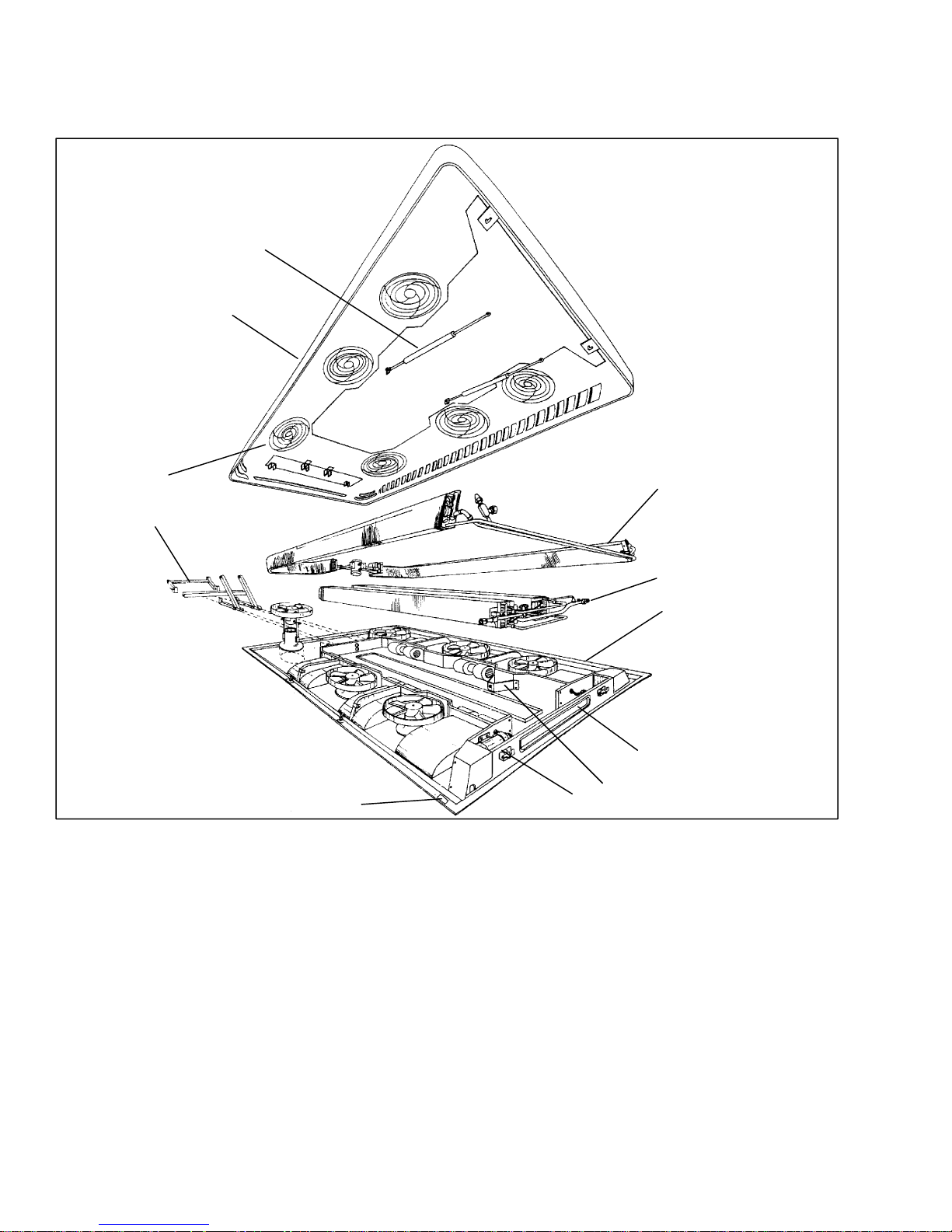
1.2.1 Apex Unit
The apex unit (see Figure 1-2) includes the condensing
2
1
section, evaporator section, Micromax electronics, and
theFresh AirSystem.All components are accessibleby
lifting the top cover. Descriptions of the systems are
provided in the following sub paragraphs.
11
10
9
1. Top Cover
2. Gas Spring (2)
3. Condenser Section (See Figure 1-3)
4. Evaporator Section (See Figure 1-4)
5. Base
6. Fresh Air System
7. Gas Spring Support (2)
8. Lock (2)
9. Serial Plate
Figure 1-2. Apex Unit Components
(GR-60 Shown)
1.2.2 Condensing Section
The condensing section (Figure 1-3) includes the
condenser coils, fan and motor assemblies, filter-drier,
receiver, liquid line solenoid valve, service valves, and
an ambient temperature sensor.
The condenser coils provide heat transfer surface for
condensing refrigerant gas at a high temperature and
3
4
5
6
7
8
10. Hinge
1 1. Condenser Fan Grille (4-GR45,
6-GR60)
12. Front Drain (2)*
13. Intermediate Drain (2)*
14. Evaporator Rear Drain (2)*
15. Condenser Rear Drain (2)*
* Not Shown
pressure into a liquid at high temperature and pressure.
The condenser fans circulate ambient air across the
outside of the condenser tubes at a temperature lower
than refrigerant circulating inside the tubes; this results
in condensation of the refrigerant into a liquid. The
filter-drier removes m oisture and debris from the liquid
refrigerant before it enters the thermostatic expansion
valve in the evaporator assembly.
T--295
1-2

The receiver collects and stores liquid refrigerant. The
receiver is fitted with upperand lowerliquid level sight
glasses to enable determining refrigerant liquid level.
The receiver is also fitted with a fusible plug which
protects the system from unsafe high pressure
conditions. The liquid line solenoid valve closes when
system is shut down to prevent flooding of coils with
liquidrefrigerant.The servicevalvesenable isolationof
the filter-drier for service. The ambient temperature
sensor measures ambient temperature and sends an
electrical signal to the controller.
The dischargecheck valve is a spring loaded, normally
closedvalve that opens withthe flowofrefrigerantfrom
the compressor. When the compressor clutch is
disengaged, the discharge check valve will close,
preventing the flow of high pressure liquid from the
condenser back into the compressor.
12 3
13
12
4
5
6
7
8
9
11
1. Condenser Coil (2)
2. Receiver
3. Protection Plate
4. Service Valve
5. Discharge Line
6. Precharge Valve
7. Liquid Line Solenoid Valve
8. Filter Drier Upper Support
Figure 1-3. Condensing Section Components
10
(GR-60 Shown)
1.2.3 Evaporator Section
The evaporator section (Figure 1-4) includes the
evaporator coils, six fan and motor assemblies,
evaporator/heater coil assemblies, a thermostatic
expansion valve and condensate drain connections.
The evaporator coils provide heat transfer surface for
transferring heat from air circulating over the outside
the coil to refrigerant circulating inside the tubes; thus
providing cooling. The heating coils provide heat
transfer surface for transferring heat from engine
coolant water circulating inside the tubes to air
9. Filter Drier
10. Filter Drier Lower Support
1 1 Condenser Fan and Motor Assembly
(4-GR45, 6-GR60)
12. Condenser Coil Fastener (4)
13. Condenser Motor Support
(4-GR45, 6-GR60)
circulating over the outside surface of the tubes, thus
providing heating. The fans circulate the air over the
coils. The air filters remove dirt particles from the air
before it passes over the coils. The thermostatic
expansion valve meters flow of refrigerant entering the
evaporator coils. The heat valve controls the flow of
enginecoolant water to the heatingcoils upon receipt of
a signal from the controller. The condensate drain
connections provide a means for connecting tubing for
disposing of condensate collected on the evaporator
coils during cooling operation.
1-3
T--295

4
1
23
5
6
7
8
9
1. Evaporator Coil With Integrated
Heating Coil (2)
2. Protection Plate
3. Expansion V alve
4. Evaporator Motor Fastening Clamps
(4-GR45, 6-GR60)
Figure 1-4. Evaporator Section Components
(GR-60 Shown)
1.2.4 Compressor Assembly
The compressor assembly includes the refrigerant
compressor, clutch assembly, suction and discharge
service valves, high pressure switch, low pressure
switch,suctionanddischargeservicing(charging) ports
and electric solenoid unloaders.
The compressor raises the pressure and temperature of
the refrigerant and forces it into the condenser tubes.
The clutch assembly provides a means of belt driving
the compressor by the bus engine. The suction and
discharge service valves enable servicing of the
compressor. Suction and discharge servicing(charging)
ports mounted on the service valves enable connection
of charging hoses for servicing of the compressor, as
well as other parts of the refrigerant circuit. The high
pressureswitch contacts open on a pressure rise to shut
down the system when abnormally high refrigerant
pressuresoccur. The electricunloaders provide a means
of controlling compressor capacity, which enables
controlof temperatureinside the bus. For more detailed
informationon the compressor, referto manual number
62-02756.
1.2.5 Fresh Air System
The Fresh Air System (6, Figure 1-2) consists of a
damperand damper operator. Thedamperoperatormay
becontrolled bythe driver,if aswitchisprovided.Inthe
automatic mode, it is controlled by the Micromax to
open and close thedamper to allow addition of fresh air
5. Evaporator Motor (4-GR45,
6-GR60)
6. Suction Line
7. Heating Lines
8. Service Valve
9. Evaporator Harness
into the air entering the evaporator coil. For additional
information on air flow, refer to paragraph 1.7.
1.2.6 System Operating Controls And Components
The system is operated by a Carrier Transicold
Micromaxmicroprocessorcontrollerwhichconsist of a
logic board (Figure 1-10), relay board (Figure 1-8 or
Figure 1-9), and manualoperator switches. The manual
operatingswitchesarelocatedon the driverscontroland
may consist of a single OEM supplied ON/OFF switch,
additional OEM supplied switches or a Carrier
Transicold supplied Micromate control panel
(Figure 1-11).The logic boardregulates the operational
cycles of the system by energizing or de--energizing
relays on the relay board in response to deviations in
interior temperature. Modes of operation include
Cooling, Heat andVent. On systems fitted with only an
ON/OFF switchand on systems withthe Micromateset
in the AUTO mode, the logic board will cycle the
system between the operating modes as required to
maintain desired set point temperature.
In the vent mode the evaporator fans are operated to
circulate air in the bus interior.
Intheheatmodetheheatvalve is opened to allow aflow
of engine coolant through the heat section of the
evaporatorcoil. The evaporatorfansoperateto circulate
air over the evaporator coil in the same manner as the
vent mode.
T--295
1-4

In the cooling mode the compressor is energized while
p
the evaporator and condenser fans are operated to
provide refrigeration as required. The compressor is
fitted with cylinder unloaders to match compressor
capacity to the bus requirements. Once interior
temperature reaches the desired set point, the system
may operate in the clutch cycle or reheat mode. A
controller programmed for clutch cycle will
de--energizethecompressorclutchandallowthesystem
to operate in the vent mode until further cooling is
required. A controller programmed for reheat will
maintain compressor operation and open the heatvalve
to allow reheating of the return air. In the reheat mode
interior temperature is maintained at the desired set
point while additional dehumidification takes place.
Controls may also be provided to allow manual
operation of the evaporator fans in low or high speed
andmanual controlofthefreshairdamper in the open or
closed position.
1.3 REFRIGERATION SYSTEM COMPONENT
SPECIFICATIONS
a. Refrigerant Charge
R--134a 14.3 lb (6.5 kg)
b. Compressor
UNIT MODEL
GR45 GR60
Compressor 05K 05G
No of Cylinders 4 6
Weight - Dry 108 lbs
(49 kg)
Oil Charge 5.5 pints
(2.6 liters)
137 lbs
(62 kg)
6.75 pints
(3.2 liters)
Oil Level:
Levelin sightglass betweenMin.--Max marks on
compressor crankcase (curbside)
Approved Compressor Oils - R-134a:
Castrol: Icematic SW68C
Mobil: EAL Arctic 68
ICI: Emkarate RL68H
c. Thermostatic Expansion Valve:
Superheat Setting (Non-externally adjustable):
10 to 12F
MOP Setting (Nonadjustable): 55 ±4 psig (3.74
±2.27 bar)
d. High Pressure Switch (HPS):
Opens at: 300 ±10 psig (20.41 ±0.68bar)
Closes at: 200 ±10 psig (13.61 ±0.68bar)
e. Low Pressure Switch (LPS)
Opens at: 6 ±3psig (0.41 ±0.20 bar)
Closes at: 25 ±3psig(1.7±0.20 bar)
1.4 ELECTRICAL SPECIFICATIONS -- MOTORS
a. Evaporator Fan Motor
ECDC* Permanent
Evaporator Motor
27.5
VDC
Magnet
24 VDC 12 VDC
Horsepower (kW) 0.34(.25) 1/8 (.09)
Full Load Amps
8.4 9.5 19
(FLA)
Operating Speed
High/Low (RPM)
4252/
3165
4200/
1850
Bearing Lubrication Factory Lubricated (addi-
tional grease not required)
b. Condenser Fan Motor
ECDC* Permanent
Condenser Motor
24 VDC 24 VDC 12 VDC
Magnet
Horsepower (kW) 0.15(.11) 1/8 (.09)
Full Load Amps
7 9 18
(FLA)
Operating Speed
High/Low (RPM)
4252/
NA
4200/
1850
Bearing Lubrication Factory Lubricated (addi-
tional grease not required)
* Electronically Communicated Direct Current
1.5 ELECTRICAL SPECIFICATIONS -- SENSORS
AND TRANSDUCERS
a. Suction and Discharge Pressure Transducer
Supply Voltage: 4.5 to 5.5 vdc (5 vdc nominal)
Supply current: 8 mA maximum
Output Range: 8K ohms minimum
Input Range: --6.7 to 450 psig (--0.46 to 30.62 bar)
Output Current: -1.5 mA minimum t o
1.5 mA maximum
Output Voltage: vdc = 0.0098 x psig + 0.4659
(See Table 4-2 for calculations.)
b. Temperature Sensors
Input Range: --52.6 to 158F (--47 to 70C)
Output: NTC 10K ohms at 77F(25C)
(See Table 4-1 for calculations.)
1.6 SAFETY DEVICES
System components are protectedfrom damage caused
by unsafe operating conditions with safety devices.
Safety devices with Carrier Transicold supplied
equipment include high pressure switch (HPS), low
pressure switch (LPS), circuit breakers and fuses.
a. Pressure Switches
High Pressure Switch (HPS)
During the A/C mode, compressor operation will
automaticallystop if the HPS switch contacts open due
toan unsafeoperatingcondition.OpeningHPScontacts
de-energizes, through the controller, the compressor
clutchshutting downthecompressor. The high pressure
switch (HPS) is installed in the center head of the
compressor.
1-5
T--295
Low Pressure Sw itch (LPS)
The low pressure switch is installed in the compressor
and opens on a pressure drop to shut down the system
whena lowpressurecondition occurs. Inaddition, ifthe
control monitors a pressure less than 10 psig (0.68
bar)by the suction pressure transducer mounted in the
evaporator section, the system will be shut down for at
least one minute.
b. Fuses and Circuit Breakers
The Relay Board is protected against high current by an
OEM supplied 150 amp fuse. Independent 15 amp
circuit breakers protect each motor while the output
circuits are protected by an additional 15 amp circuit
breaker.Duringahigh currentcondition,the breaker(or
OEM fuse) may open. When power is removed from a
device, a breaker alarm will be generated.
c. Ambient Lockout
The ambient temperature sensor located in the
condenser section measures the condenser inlet air
temperature. When the temperatureis below the cut out
set point the compressor is locked out until the
temperaturerisesabovethecutin setting. The set points
maybe programmedto cutoutat45F7.2C)andcutin
at 50F10C) or cut out at 25 F--3.9C) and cut in at
45F7.2C) in accordance with bus purchase
specification.This setting protects the compressorfrom
damage caused by operation at low pressures.
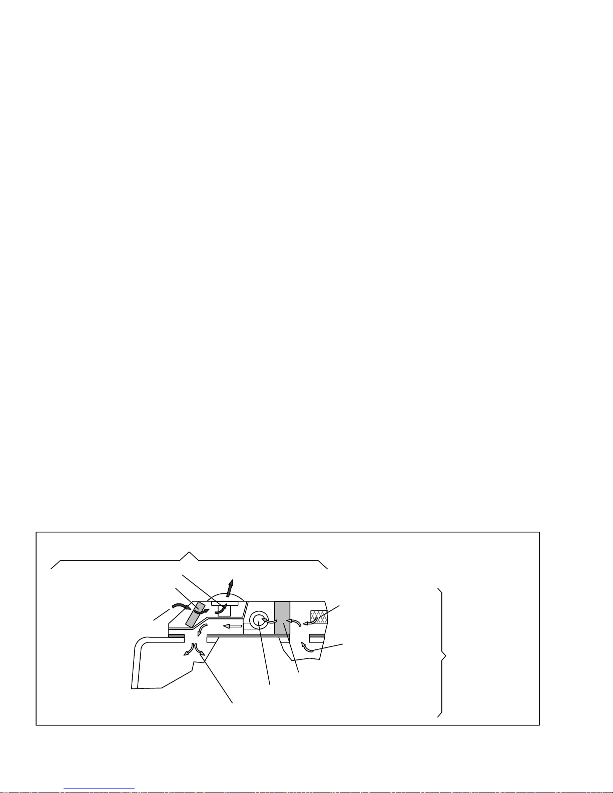
1.7 AIR FLOW
The paths for ambient air through the condenser and
coach air through the evaporator are illustrated in
Figure 1-5.
1.8 AIR CONDITIONING REFRIGERATION
CYCLE
When air conditioning (cooling) is selected by the
controller, the unit operates as a vapor compression
system using R-134a as a refrigerant (see Figure 1-6).
The main components of the system are the
reciprocating compressor, air-cooled condenser coils,
receiver, filter-drier, thermostatic expansion valve,
liquid line solenoid valve and evaporator coils.
The compressor raises thepressureand thetemperature
of the refrigerant and forcesit into the condenser tubes.
The condenser fan circulates surrounding air (which is
at a temperature lower than the refrigerant) over the
outside of the condenser tubes. Heat transfer is
establishedfrom the refrigerant (inside the tubes) to the
condenser air (flowing over the tubes). The condenser
tubes have fins designed to improve the transfer ofheat
from the refrigerant gas to the air; this removal of heat
causes the refrigerant to liquefy, thus liquid refrigerant
leaves the condenser and flows to the receiver.
The receiver serves as a liquid refrigerant reservoir so
that a constant supply of liquid is available to the
evaporators as needed, and acts as a storage space when
pumping down the system. The receiver is equipped
with sight glasses to observe the refrigerant for
restricted flow and correct charge level.
The refrigerant leaves the receiver and passes through
the receiver outlet/service valve, through a filter-drier
where an absorbent keeps the refrigerantclean and dry.
From the filter-drier, the liquid refrigerant then flows
through the liquid line solenoid valve to the
thermostatic expansion valve. the thermal expansion
valve reduce pressure and temperatureof the liquid and
metersthe flow of liquid refrigerant tothe evaporatorto
obtain maximum use of the evaporator heat transfer
surface.
Thelow pressure,lowtemperatureliquidthatflowsinto
the evaporator tubes is colder than the air that is
circulated over the evaporator tubes by the evaporator
fans (fans). Heat transfer is established from the
evaporatorair (flowing over the tubes)to the refrigerant
(flowing inside the tubes). The evaporator tubes have
aluminum fins to increase heat transfer from the air to
the refrigerant; therefore the cooler air is circulated to
the interior of thebus. Liquidline solenoid valvecloses
during shutdown to prevent refrigerant flow.
The transfer of heat from the air to the low temperature
liquid refrigerant in the evaporator causes the liquid to
vaporize. This low temperature, low pressure vapor
passes through the suction line and returns to the
compressor where the cycle repeats.
CONDENSER AIR FLOW
3. THROUGH FAN
2. THROUGH CONDENSER
1. FROM AMBIENT
T--295
4. RETURN TO AMBIENT
1. FROM DAMPER
3. THROUGH EVAPORAT OR
4. THROUGH FAN
5. RETURN TO COACH
Figure 1-5. Air Flow Paths
1-6
(IF ACTIVE)
2. FROM COACH
EVAPORATOR
AIR
FLOW

12
45
3
6
7
8
9
16
A
A
DISCHARGE
LIQUID
SUCTION
RECEIVER
VIEW A-A
16
17
18
MAIN ENGINE
RADIATOR
10
11
12
13
11
14
15
SUCTION
DISCHARGE
1. Condenser Fan Assembly
2. Evaporator Fan Assembly
3. Expansion V alve
4. Expansion V alve Equalizer Line
5. Liquid Line
6. Precharge Valve
7. Expansion V alve Bulb
8. Pressure Transducer, Low Side
9. Service Port, Low Side
10. Pressure Transducer, High Side
11. Service Valve With Port
12. Liquid Line Solenoid Valve
13. Filter Drier
14. Service Port, High Side
15. Discharge Check Valve
16. Receiver
17. Refrigerant Sight Glass
18. Moisture Indicator
Figure 1-6. Refrigerant Flow Diagram
(GR60 Shown)
1-7
COMPRESSOR
T--295

SUPPLY
RETURN
Figure 1-7. Heating Cycle Flow Diagram
(GR60 Shown)
1.9 HEATING CYCLE
Heating circuit (Figure 1-7) components furnished by
Carrier Transicold include the integral evaporator coil
heater cores and a solenoid operated heat valve.
Componentsfurnishedby the bus manufacturerinclude
auxiliary heater and boost water pump. The controller
automaticallycontrols theheat valveduring theheating
and reheat modes to maintain required temperatures
HEAT
VALVE
BOOST
PUMP
MAIN ENGINE
RADIATOR
COMPRESSOR
inside the bus. Engine coolant (glycol solution) is
circulatedthrough the heating circuitby the engine and
an auxiliary boost water pump. When the heat valve
solenoid i s energized, the valve will open to allow
enginecoolanttoflowthrough theheatercoil. Thevalve
is normally closed so that if a failureoccurs, the system
will be able to cool.
T--295
1-8
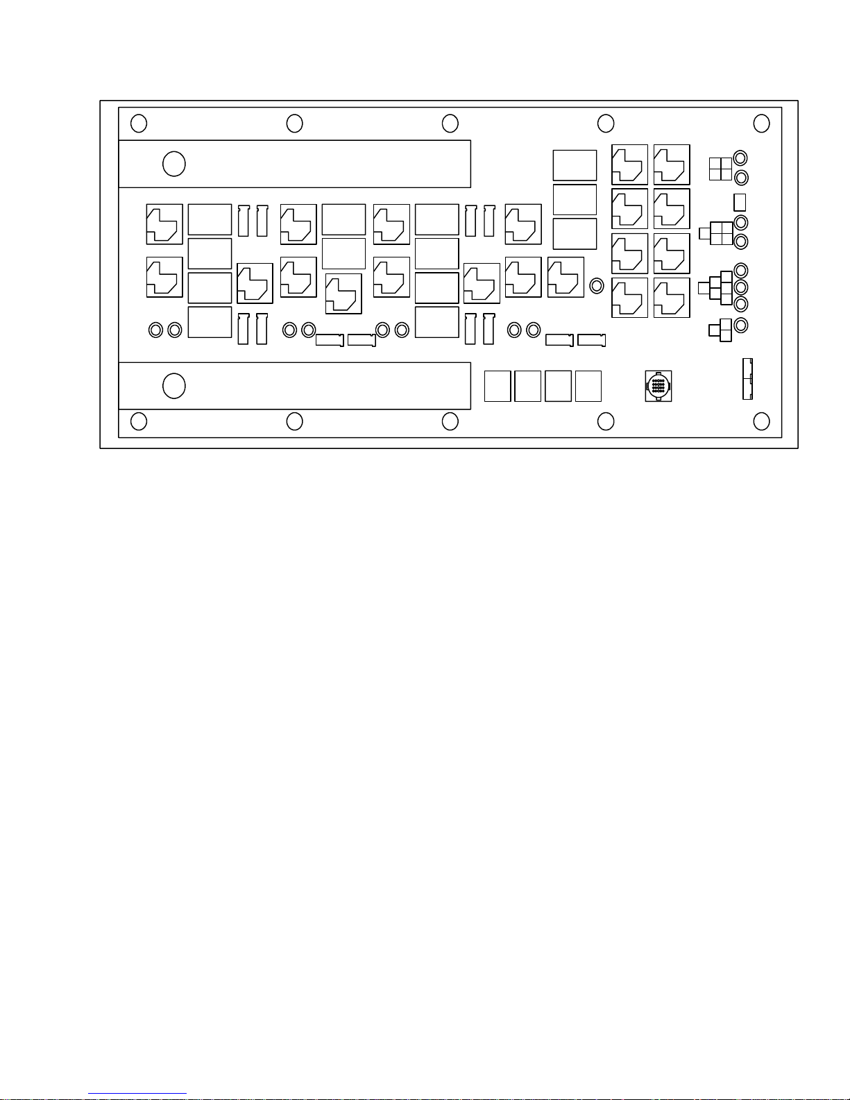
1.10 RELAY BOARD
1.10.1 Permanent Magnet Motors with 2 speed switching from series to parallel connection (Option 1)
JP6
K1
K2
D2 D6
CB 1
CB 2
CB 3
CB 4
EF1
EF2
K5
EF4EF3
D14
K3
K4
D17
EF6
CB 5
CB 6
K6
D26 D30
EF5
K7
K8
CB 7
CB 8
CB 9
CB 10
CF1
CF3
CF2
K11
CF4
K9
K10
D38 D41
K22K24
CB 13
CB 11
CB 12
K12
CF6 CF5
K23K21
K15K14
K17K16
K20K18
D85
K13K19
JP1
1
D57
3
4
2
D54
JP5
4
23
1
1
D63
5
D60
JP4
D72
4
2
5 6
D66
3
D51
JP3
23
1
D69
JP2
Figure 1-8 Relay Board (Option 1)
a. Relays
K1 Energizes evaporator fans 1 & 2 in high speed
or evaporator fans 1,2,3 & 4 in low speed.
K2 Energizes evaporator fans 3 & 4 in high speed
(not energized in low speed).
K3 Energizes evaporator fan 5 in high speed or
evaporator fans 5 & 6 in low speed.
K4 Energizes evaporator fan 6 in high speed (not
energized in low speed).
K5 Connects the negative side of evaporator fans
1 & 2 to ground in high speed. Connects the
negative side of evaporator fans 1 & 2 to
positive side of evaporator fans 3 & 4 in
low speed
K6 Connects the negative side of evaporator fan
5 to ground in high speed. Connects the
negative side of evaporator fan 5 to
positive side of evaporator fan 6 in
low speed
K 7 Energizes condenser fans 1 & 2 in high speed
or condenser fans 1,2,3 & 4 in low speed
K 8 Energizes condenser fans 3 & 4 in high speed
(not energized in low speed).
K 9 Energizes condenser fan 5 in high speed or
condenser fans 5 & 6 in low speed.
K10 Energizes condenser fan 6 in high speed
(not energized in low speed).
K11 Connects the negative side of condenser fans
1 & 2 to ground in high speed. Connects the
negative side of condenser fans 1 & 2 to
the positive side of condenser fans 3 & 4 in
low speed.
K12 Connects the negative side of condenser fan
5 to ground in high speed. Connects the
negative side of condenser fan 5 to
the positive side of condenser fan 6 in
low speed.
K13 Energizes the A/C clutch.
K14 Energizes unloader 1.
K15 Energizes unloader 2.
K16 Energizes the fresh air damper.
K17 Energizes the heat valve.
K18 Energizes the fault light output.
K19 Energizes the Boost Pump.
K20 Energizes the spare output.
K21 Is energized by the logic board to turn the
evaporator fans on high. The contacts of this
relay energize the coils of relays K1, K2,
K3 & K4.
K22 Is energized by the logic board to turn the
evaporator fans on low. The contacts of this
relay energize the coils of relays K1, K3,
K5 & K6.
K23 Is energized by the logic board to turn the
condenser fans on high. The contacts of this
relay energize the coils of relays K7, K8,
K9 & K10.
K24 Is energized by the logic board to turn the
condenser fans on low. The contacts of this
relay energize the coils of relays K7, K9,
K11 & K12.
1-9
T--295
 Loading...