


Bus Air
Conditioning
Equipment
Models
GR--45
GR--60
(N.A.O.)
T--295
AC Pressure Sensor

OPERATION AND
SERVICE MANUAL
BUS
AIR CONDITIONING
UNIT
Models
Carrier Refrigeration Operations
Carrier Transicold Division, Carrier Corporation, P.O. Box 4805, Syracuse, N.Y. 13221 U. S. A.
Carrier Corporation 2000 D Printed in U. S. A. 0300
GR--45
GR--60
(N.A.O.)
AC Pressure Sensor

SAFETY SUMMARY
GENERAL SAFETY NOTICES
The following general safety notices supplement the specific warnings and cautions appearing elsewhere in this
manual. They are recommended precautions that must be understood and applied during operation and maintenance
of the equipment covered herein. A listing of the specific warnings and cautions appearing elsewhere in the manual
follows the general safety notices.
FIRST AID
Aninjury,no matterhow slight, should nevergo unattended.Alwaysobtain firstaidormedicalattentionimmediately.
OPERATING PRECAUTIONS
Always wear safety glasses.
Keep hands, clothing and tools clear of the evaporator and condenser fans.
No work should be performed on the unit until all circuit breakers and start-stop switches are placed in the OFF
position, and power supply is disconnected.
Always work in pairs. Never work on the equipment alone.
In case of severe vibration or unusual noise, stop t he unit and investigate.
MAINTENANCE PRECAUTIONS
Beware of unannounced starting of the evaporator and condenser fans. Do not open the unit cover before turning
power off.
Besurepoweristurnedoffbeforeworkingon motors, controllers, solenoid valves and electricalcontrols. Tagcircuit
breaker and power supply to prevent accidental energizing of circuit.
Do not bypass any electrical safety devices, e.g. bridging an overload, or using any sort of jumper wires. Problems
with the system should be diagnosed, and any necessary repairs performed, by qualified service personnel.
Whenperforming any arcweldingon the unit, disconnect allwireharnessconnectors from the modulesin the control
box. Do not remove wire harnessfrom the modules unless you aregrounded to the unit frame with a static-safewrist
strap.
In case of electrical fire, open circuit switch and extinguish with CO
SPECIFIC WARNINGS AND CAUTIONS
(never use water).
2
WARNING
DO NOT USE A NITROGEN CYLINDER WITHOUT A PRESSURE REGULATOR
WARNING
DO NOT USEOXYGEN IN OR NEAR A REFRIGERATION SYSTEM AS AN EXPLOSIONMAY
OCCUR.
WARNING
THE FILTER-DRIER MAY CONTAIN LIQUID REFRIGERANT. SLOWLY LOOSEN THE
FLARE NUTS AND AVOID CONTACT WITH EXPOSED SKIN OR EYES.
CAUTION
Donot under anycircumstancesattempt toservicethemicroprocessor. should aproblem developwith
the microprocessor, replace it.
CAUTION
If unit was recently operated, be careful of remaining hot coolant in the hoses when disassembling.
Safety-1
AC Pressure Sensor
T--295

TABLE OF CONTENTS
PARAGRAPH NUMBER Page
SAFETY SUMMARY Safety-1.....................................................................
DESCRIPTION 1-1...............................................................................
1.1 INTRODUCTION 1-1..............................................................
1.2 GENERAL DESCRIPTION 1-2......................................................
1.2.1 Apex Unit 1-2..................................................................
1.2.2 Condensing S ection 1-2..........................................................
1.2.3 Evaporator Section 1-3...........................................................
1.2.4 Compressor Assembly 1-4........................................................
1.2.5 Fresh Air System 1-4............................................................
1.2.6 System Operating Controls And Components 1-4.....................................
1.3 REFRIGERATION SYSTEM COMPONENT SPECIFICATIONS 1-5........................
1.4 ELECTRICAL SPECIFICATIONS -- MOTORS 1-5......................................
1.5 ELECTRICAL SPECIFICATIONS -- SENSORS AND TRANSDUCERS 1-5..................
1.6 SAFETY DEVICES 1-5.............................................................
1.7 AIR FLOW 1-6....................................................................
1.8 AIR CONDITIONING REFRIGERATION CYCLE 1-6...................................
1.9 HEATING CYCLE 1-8.............................................................
1.10 RELAY BOARD 1-9...............................................................
1.10.1 Permanent Magnet Motors with 2 speed switching from series to parallel
connection (Option 1) 1-9........................................................
1.10.2 Electronically Communtated DC Motors with 2--speed Evaporator Input Signal (Option 2) 1-11.
1.11 LOGIC BOARD 1-12................................................................
1.12 CONTROL PANEL (Diagnostic Module) 1-13............................................
OPERATION 2-1.................................................................................
2.1 STARTING, STOPPING AND OPERATING INSTRUCTIONS 2-1..........................
2.1.1 Power to Logic Board 2-1........................................................
2.1.2 Starting 2-1....................................................................
2.1.3 Self-Test and Diagnostics (Check for Errors and/or Alarms) 2-1..........................
2.1.4 Stopping 2-1...................................................................
2.2 PRE--TRIP INSPECTION 2-1........................................................
2.3 MODES OF OPERATION 2-3.......................................................
2.3.1 Temperature Control 2-3.........................................................
2.3.2 Cooling Mode 2-3..............................................................
2.3.3 Heating Mode 2-3..............................................................
2.3.4 Boost Pump 2-3................................................................
2.3.5 Vent Mode 2-3.................................................................
2.3.6 Fresh Air System 2-3............................................................
2.3.7 Compressor Unloader Control 2-3..................................................
2.3.8 Evaporator Fan Speed Selection 2-4................................................
2.3.9 Condenser Fan Control 2-4.......................................................
2.3.10 Compressor Clutch Control 2-4....................................................
i T--295

TABLE OF CONTENTS (Continued)
PARAGRAPH NUMBER Page
2.3.11 Alarm Description 2-4...........................................................
2.3.12 Hour Meters 2-4................................................................
2.4 MICROPROCESSOR DIAGNOSTICS 2-4..........................................
2.4.1 Connecting 2-4.................................................................
2.4.2 Control 2-5....................................................................
2.4.3 Diagnostic Mode 2-5............................................................
2.4.4 System Parameters 2-5...........................................................
2.4.5 Test Mode 2-5.................................................................
TROUBLESHOOTING 3-1.........................................................................
3.1 SELF DIAGNOSTICS 3-1...........................................................
3.2 SYSTEM ALARMS 3-1............................................................
3.2.1 Alarm Codes 3-1...............................................................
3.2.2 Activation 3-1.................................................................
3.2.3 Alarm Queue 3-1...............................................................
3.2.4 Alarm Clear 3-1................................................................
3.3 TROUBLESHOOTING 3-1..........................................................
3.3.1 System Will Not Cool 3-4........................................................
3.3.2 System R uns But Has Insufficient C ooling 3-4........................................
3.3.3 Abnormal Pressures 3-4..........................................................
3.3.4 Abnormal Noise Or Vibrations 3-4.................................................
3.3.5 Control System Malfunction 3-5...................................................
3.3.6 No Evaporator Air Flow Or Restricted Air Flow 3-5...................................
3.3.7 Expansion Valve Malfunction 3-5..................................................
3.3.8 Heating Malfunction 3-5.........................................................
SERVICE 4-1....................................................................................
4.1 MAINTENANCE SCHEDULE 4-1....................................................
4.2 OPENING TOP COVER 4-1.........................................................
4.3 SUCTION AND DISCHARGE SERVICE VALVES 4-1...................................
4.4 INSTALLING MANIFOLD GAUGE SET 4-2...........................................
4.5 PUMPING THE SYSTEM DOWN OR REMOVING THE REFRIGERANT CHARGE 4-2.......
4.5.1 System Pump Down For Low Side Repair 4-2........................................
4.5.2 Refrigerant Removal From An Inoperative Compressor. 4-3.............................
4.5.3 Pump Down An Operable Compressor For Repair 4-3..................................
4.5.4. Removing Entire System Charge 4-4................................................
4.6 REFRIGERANT LEAK CHECK 4-4..................................................
4.7 EVACUATION AND DEHYDRATION 4-4.............................................
4.7.1 General 4-4....................................................................
4.7.2 Preparation 4-4.................................................................
4.7.3 Procedure for Evacuation and Dehydrating System 4-4.................................
T--295
ii

TABLE OF CONTENTS (Continued)
PARAGRAPH NUMBER Page
4.8 ADDING REFRIGERANT TO SYSTEM 4-5...........................................
4.8.1 Checking Refrigerant Charge 4-5..................................................
4.8.2 Adding Full Charge 4-5..........................................................
4.8.3 Adding Partial Charge 4-5........................................................
4.9 CHECKING FOR NONCONDENSIBLES 4-5...........................................
4.10 CHECKING AND REPLACING HIGH PRESSURE SWITCH 4-5..........................
4.11 FILTER-DRIER 4-6................................................................
4.11.1 To Check Filter--Drier 4-6.........................................................
4.11.2 To Replace Filter--Drier 4-6.......................................................
4.12 CONDENSER COIL REPLACEMENT 4-6.............................................
4.13 EVAPORATOR COIL REPLACEMENT 4-7............................................
4.14 SERVICING THE HEAT VALVE 4-7..................................................
4.14.1 COIL REPLACEMENT 4-7......................................................
4.14.2 INTERNAL PART REPLACEMENT 4-7............................................
4.14.3 REPLACE ENTIRE VALVE 4-7...................................................
4.15 SERVICING THE LIQUID LINE SOLENOID VALVE 4-8.................................
4.15.1 Coil Replacement 4-8............................................................
4.15.2 Internal Part Replacement 4-8.....................................................
4.15.3.Replace Entire Valve 4-8.........................................................
4.16 CONDENSER FAN/MOTOR ASSEMBLY 4-8..........................................
4.16.1 Removal 4-8...................................................................
4.16.2 Inspection And Cleaning 4-9......................................................
4.16.3 Brush Replacement 4-9..........................................................
4.17 REPLACING EVAPORATOR FAN 4-9................................................
4.18 REPLACING RETURN AIR FILTERS 4-9.............................................
4.19 THERMOSTATIC EXPANSION VALVE 4-9............................................
4.19.1 Valve Replacement 4-9..........................................................
4.19.2 Superheat Measurement 4-10.......................................................
4.20 COMPRESSOR MAINTENANCE 4-10.................................................
4.20.1 Removing the Compressor 4-10....................................................
4.20.2 Transferring Compressor Clutch 4-11................................................
4.20.3 Compressor Oil Level 4-12........................................................
4.20.4 Checking Unloader Operation 4-12..................................................
4.21 TEMPERATURE SENSOR CHECKOUT 4-13...........................................
4.22 PRESSURE TRANSDUCER CHECKOUT 4-13..........................................
4.23 REPLACING SENSORS AND TRANSDUCERS 4-13.....................................
4.24 LOGIC BOARD CONFIGURATION 4-13...............................................
ELECTRICAL 5-1................................................................................
5--1 INTRODUCTION 5-1...............................................................
INDEX Index-1..................................................................................
iii T--295

LIST OF ILLUSTRATIONS
FIGURE NUMBER Page
Figure 1-1. A/C Component Identification 1-1..................................................
Figure 1-2. Apex Unit Components 1-2........................................................
Figure 1-3. Condensing Section Components 1-3................................................
Figure 1-4. Evaporator Section Components 1-4.................................................
Figure 1-5. Air Flow Paths 1-6..............................................................
Figure 1-6. Refrigerant Flow Diagram 1-7.....................................................
Figure 1-7. Heating Cycle Flow Diagram 1-8...................................................
Figure 1-8 Relay Board (Option 1) 1-9........................................................
Figure 1-9 Relay Board (Option 2) 1-11........................................................
Figure 1-10 Logic Board 1-12................................................................
Figure 1-11. Micromate Control Panel 1-13.....................................................
Figure 2-1 Capacity Control Diagram 2-2......................................................
Figure 4-1. Opening Top Cover 4-1...........................................................
Figure 4-2.Suction or Discharge Service Valve 4-2...............................................
Figure 4-3. Manifold Gauge Set 4-2..........................................................
Figure 4-4. Low Side Pump Down Connections 4-3..............................................
Figure 4-5. Compressor Service Connections 4-3................................................
Figure 4-6. S ystem Charge Removal Connections 4-4............................................
Figure 4-7. Checking High Pressure Switch 4-6.................................................
Figure 4-8. Filter--Drier Removal 4-6.........................................................
Figure 4-9. Heat Valve 4-7..................................................................
Figure 4-10. Liquid Line Solenoid Valve 4-8...................................................
Figure 4-11. Condenser Fan/Motor Assembly 4-8................................................
Figure 4-12. Evaporator Fan Removal 4-9.....................................................
Figure 4-13. Thermostatic Expansion Valve 4-9.................................................
Figure 4-14.Thermostatic Expansion Valve Bulb and Thermocouple 4-10..............................
Figure 4-15.Removing Bypass Piston Plug 4-11..................................................
Figure 4-16. Compressor C lutch 4-11..........................................................
Figure 4-17. Compressors 4-12...............................................................
Figure 4-18 Transducer Terminal Location 4-13..................................................
Figure 5--1. Electrical Wiring Schematic Diagram - Legend 5-2.....................................
Figure 5--2. Wiring Schematic, Permanent Magnet Motors - Interconnection 5-3.......................
Figure 5--3. Wiring Schematic, Permanent Magnet Motors - Relays to External Components 5-4..........
Figure 5--4. Wiring Schematic, Electronically Communtated Motors - Interconnection 5-5...............
Figure 5--5. Wiring Schematic, Electronically Communtated Motors - Relays To External Components 5-6..
T--295
iv

LIST OF TABLES
TABLE NUMBER Page
Table 2-1. Evaporator Fan Speed Relay Operation 2-4.............................................
Table 2-2. C ontroller Test List 2-5.............................................................
Table 2-3. Parameter Codes 2-6...............................................................
Table 3-2 Alarm Codes 3-2..................................................................
Table 3-3 General System Troubleshooting Procedures 3-4.........................................
Table 4-1. Temperature Sensor Resistance 4-13...................................................
Table 4-2. PressureTransducer Voltage 4-14......................................................
Table 4-3. Logic Board Configuration 4-14.......................................................
v T--295

SECTION 1
DESCRIPTION
1.1 INTRODUCTION
This manual contains Operating Instructions, Service
Instructions and Electrical Data for the Model GR Air
Conditioning and Heating equipment furnished by
Carrier Transicold Division as shown in Table 1-1.
ModelGR systems consistsofan ApexUnit,containing
the condenser and evaporator and an engine
compartment mounted compressor. To complete the
Table 1-1. Model
MODEL
GR45 ROOF MOUNTED 05K 4 4
SERIES COMPRESSOR CONDENSER
GR60 ROOF MOUNTED 05G 6 6
Table 1-2. Additional Support Manuals
MANUAL/FORM NUMBER
EQUIPMENT COVERED TYPE OF MANUAL
62--02491 O5K Compressor Operation and Service
62--02460 O5K Compressor Parts List
62--02756 O5G Compressor Operation and Service
T--200 O5G Compressor Parts List
system, the air conditioning and heating equipment
interfaces with electrical cabling, refrigerant piping,
enginecoolant piping (forheating), duct work andother
components furnished by the bus manufacturer.
Operation of the units is controlled automatically by a
microprocessor based Micromax Controller which
maintains the vehicle’s interior temperature at the
desired set point.
FANS
EVAPORATOR
FANS
4
3
2
1
13
1. Compressor
2. Refrigerant Lines
3. Compressor Harness
4. Heat Valve
5. Electronics Boards
6. Apex Unit
7. Main Harness
5
Figure 1-1. A/C Component Identification
6
12 10 9
11
7
8. Driver Control
9. Power Harness
10. Power Relay
11. Battery
12. Alternator
13. Discharge Check Valve
8
1-1
T--295
1.2 GENERAL DESCRIPTION
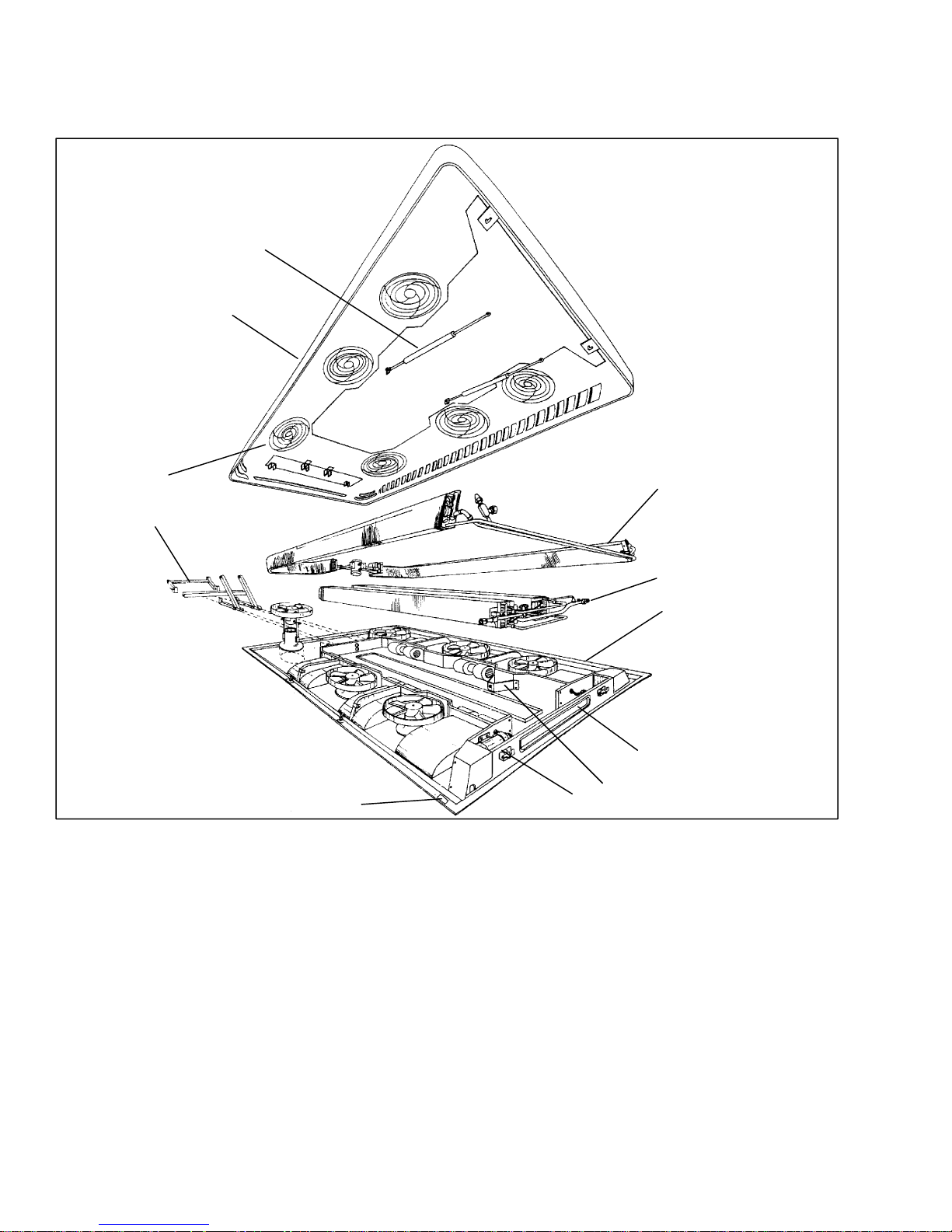
1.2.1 Apex Unit
The apex unit (see Figure 1-2) includes the condensing
2
1
section, evaporator section, Micromax electronics, and
theFresh AirSystem.All components are accessibleby
lifting the top cover. Descriptions of the systems are
provided in the following sub paragraphs.
11
10
9
1. Top Cover
2. Gas Spring (2)
3. Condenser Section (See Figure 1-3)
4. Evaporator Section (See Figure 1-4)
5. Base
6. Fresh Air System
7. Gas Spring Support (2)
8. Lock (2)
9. Serial Plate
Figure 1-2. Apex Unit Components
(GR-60 Shown)
1.2.2 Condensing Section
The condensing section (Figure 1-3) includes the
condenser coils, fan and motor assemblies, filter-drier,
receiver, liquid line solenoid valve, service valves, and
an ambient temperature sensor.
The condenser coils provide heat transfer surface for
condensing refrigerant gas at a high temperature and
3
4
5
6
7
8
10. Hinge
1 1. Condenser Fan Grille (4-GR45,
6-GR60)
12. Front Drain (2)*
13. Intermediate Drain (2)*
14. Evaporator Rear Drain (2)*
15. Condenser Rear Drain (2)*
* Not Shown
pressure into a liquid at high temperature and pressure.
The condenser fans circulate ambient air across the
outside of the condenser tubes at a temperature lower
than refrigerant circulating inside the tubes; this results
in condensation of the refrigerant into a liquid. The
filter-drier removes m oisture and debris from the liquid
refrigerant before it enters the thermostatic expansion
valve in the evaporator assembly.
T--295
1-2

The receiver collects and stores liquid refrigerant. The
receiver is fitted with upperand lowerliquid level sight
glasses to enable determining refrigerant liquid level.
The receiver is also fitted with a fusible plug which
protects the system from unsafe high pressure
conditions. The liquid line solenoid valve closes when
system is shut down to prevent flooding of coils with
liquidrefrigerant.The servicevalvesenable isolationof
the filter-drier for service. The ambient temperature
sensor measures ambient temperature and sends an
electrical signal to the controller.
The dischargecheck valve is a spring loaded, normally
closedvalve that opens withthe flowofrefrigerantfrom
the compressor. When the compressor clutch is
disengaged, the discharge check valve will close,
preventing the flow of high pressure liquid from the
condenser back into the compressor.
12 3
13
12
4
5
6
7
8
9
11
1. Condenser Coil (2)
2. Receiver
3. Protection Plate
4. Service Valve
5. Discharge Line
6. Precharge Valve
7. Liquid Line Solenoid Valve
8. Filter Drier Upper Support
Figure 1-3. Condensing Section Components
10
(GR-60 Shown)
1.2.3 Evaporator Section
The evaporator section (Figure 1-4) includes the
evaporator coils, six fan and motor assemblies,
evaporator/heater coil assemblies, a thermostatic
expansion valve and condensate drain connections.
The evaporator coils provide heat transfer surface for
transferring heat from air circulating over the outside
the coil to refrigerant circulating inside the tubes; thus
providing cooling. The heating coils provide heat
transfer surface for transferring heat from engine
coolant water circulating inside the tubes to air
9. Filter Drier
10. Filter Drier Lower Support
1 1 Condenser Fan and Motor Assembly
(4-GR45, 6-GR60)
12. Condenser Coil Fastener (4)
13. Condenser Motor Support
(4-GR45, 6-GR60)
circulating over the outside surface of the tubes, thus
providing heating. The fans circulate the air over the
coils. The air filters remove dirt particles from the air
before it passes over the coils. The thermostatic
expansion valve meters flow of refrigerant entering the
evaporator coils. The heat valve controls the flow of
enginecoolant water to the heatingcoils upon receipt of
a signal from the controller. The condensate drain
connections provide a means for connecting tubing for
disposing of condensate collected on the evaporator
coils during cooling operation.
1-3
T--295

4
1
23
5
6
7
8
9
1. Evaporator Coil With Integrated
Heating Coil (2)
2. Protection Plate
3. Expansion V alve
4. Evaporator Motor Fastening Clamps
(4-GR45, 6-GR60)
Figure 1-4. Evaporator Section Components
(GR-60 Shown)
1.2.4 Compressor Assembly
The compressor assembly includes the refrigerant
compressor, clutch assembly, suction and discharge
service valves, high pressure switch, low pressure
switch,suctionanddischargeservicing(charging) ports
and electric solenoid unloaders.
The compressor raises the pressure and temperature of
the refrigerant and forces it into the condenser tubes.
The clutch assembly provides a means of belt driving
the compressor by the bus engine. The suction and
discharge service valves enable servicing of the
compressor. Suction and discharge servicing(charging)
ports mounted on the service valves enable connection
of charging hoses for servicing of the compressor, as
well as other parts of the refrigerant circuit. The high
pressureswitch contacts open on a pressure rise to shut
down the system when abnormally high refrigerant
pressuresoccur. The electricunloaders provide a means
of controlling compressor capacity, which enables
controlof temperatureinside the bus. For more detailed
informationon the compressor, referto manual number
62-02756.
1.2.5 Fresh Air System
The Fresh Air System (6, Figure 1-2) consists of a
damperand damper operator. Thedamperoperatormay
becontrolled bythe driver,if aswitchisprovided.Inthe
automatic mode, it is controlled by the Micromax to
open and close thedamper to allow addition of fresh air
5. Evaporator Motor (4-GR45,
6-GR60)
6. Suction Line
7. Heating Lines
8. Service Valve
9. Evaporator Harness
into the air entering the evaporator coil. For additional
information on air flow, refer to paragraph 1.7.
1.2.6 System Operating Controls And Components
The system is operated by a Carrier Transicold
Micromaxmicroprocessorcontrollerwhichconsist of a
logic board (Figure 1-10), relay board (Figure 1-8 or
Figure 1-9), and manualoperator switches. The manual
operatingswitchesarelocatedon the driverscontroland
may consist of a single OEM supplied ON/OFF switch,
additional OEM supplied switches or a Carrier
Transicold supplied Micromate control panel
(Figure 1-11).The logic boardregulates the operational
cycles of the system by energizing or de--energizing
relays on the relay board in response to deviations in
interior temperature. Modes of operation include
Cooling, Heat andVent. On systems fitted with only an
ON/OFF switchand on systems withthe Micromateset
in the AUTO mode, the logic board will cycle the
system between the operating modes as required to
maintain desired set point temperature.
In the vent mode the evaporator fans are operated to
circulate air in the bus interior.
Intheheatmodetheheatvalve is opened to allow aflow
of engine coolant through the heat section of the
evaporatorcoil. The evaporatorfansoperateto circulate
air over the evaporator coil in the same manner as the
vent mode.
T--295
1-4

In the cooling mode the compressor is energized while
p
the evaporator and condenser fans are operated to
provide refrigeration as required. The compressor is
fitted with cylinder unloaders to match compressor
capacity to the bus requirements. Once interior
temperature reaches the desired set point, the system
may operate in the clutch cycle or reheat mode. A
controller programmed for clutch cycle will
de--energizethecompressorclutchandallowthesystem
to operate in the vent mode until further cooling is
required. A controller programmed for reheat will
maintain compressor operation and open the heatvalve
to allow reheating of the return air. In the reheat mode
interior temperature is maintained at the desired set
point while additional dehumidification takes place.
Controls may also be provided to allow manual
operation of the evaporator fans in low or high speed
andmanual controlofthefreshairdamper in the open or
closed position.
1.3 REFRIGERATION SYSTEM COMPONENT
SPECIFICATIONS
a. Refrigerant Charge
R--134a 14.3 lb (6.5 kg)
b. Compressor
UNIT MODEL
GR45 GR60
Compressor 05K 05G
No of Cylinders 4 6
Weight - Dry 108 lbs
(49 kg)
Oil Charge 5.5 pints
(2.6 liters)
137 lbs
(62 kg)
6.75 pints
(3.2 liters)
Oil Level:
Levelin sightglass betweenMin.--Max marks on
compressor crankcase (curbside)
Approved Compressor Oils - R-134a:
Castrol: Icematic SW68C
Mobil: EAL Arctic 68
ICI: Emkarate RL68H
c. Thermostatic Expansion Valve:
Superheat Setting (Non-externally adjustable):
10 to 12F
MOP Setting (Nonadjustable): 55 ±4 psig (3.74
±2.27 bar)
d. High Pressure Switch (HPS):
Opens at: 300 ±10 psig (20.41 ±0.68bar)
Closes at: 200 ±10 psig (13.61 ±0.68bar)
e. Low Pressure Switch (LPS)
Opens at: 6 ±3psig (0.41 ±0.20 bar)
Closes at: 25 ±3psig(1.7±0.20 bar)
1.4 ELECTRICAL SPECIFICATIONS -- MOTORS
a. Evaporator Fan Motor
ECDC* Permanent
Evaporator Motor
27.5
VDC
Magnet
24 VDC 12 VDC
Horsepower (kW) 0.34(.25) 1/8 (.09)
Full Load Amps
8.4 9.5 19
(FLA)
Operating Speed
High/Low (RPM)
4252/
3165
4200/
1850
Bearing Lubrication Factory Lubricated (addi-
tional grease not required)
b. Condenser Fan Motor
ECDC* Permanent
Condenser Motor
24 VDC 24 VDC 12 VDC
Magnet
Horsepower (kW) 0.15(.11) 1/8 (.09)
Full Load Amps
7 9 18
(FLA)
Operating Speed
High/Low (RPM)
4252/
NA
4200/
1850
Bearing Lubrication Factory Lubricated (addi-
tional grease not required)
* Electronically Communicated Direct Current
1.5 ELECTRICAL SPECIFICATIONS -- SENSORS
AND TRANSDUCERS
a. Suction and Discharge Pressure Transducer
Supply Voltage: 4.5 to 5.5 vdc (5 vdc nominal)
Supply current: 8 mA maximum
Output Range: 8K ohms minimum
Input Range: --6.7 to 450 psig (--0.46 to 30.62 bar)
Output Current: -1.5 mA minimum t o
1.5 mA maximum
Output Voltage: vdc = 0.0098 x psig + 0.4659
(See Table 4-2 for calculations.)
b. Temperature Sensors
Input Range: --52.6 to 158F (--47 to 70C)
Output: NTC 10K ohms at 77F(25C)
(See Table 4-1 for calculations.)
1.6 SAFETY DEVICES
System components are protectedfrom damage caused
by unsafe operating conditions with safety devices.
Safety devices with Carrier Transicold supplied
equipment include high pressure switch (HPS), low
pressure switch (LPS), circuit breakers and fuses.
a. Pressure Switches
High Pressure Switch (HPS)
During the A/C mode, compressor operation will
automaticallystop if the HPS switch contacts open due
toan unsafeoperatingcondition.OpeningHPScontacts
de-energizes, through the controller, the compressor
clutchshutting downthecompressor. The high pressure
switch (HPS) is installed in the center head of the
compressor.
1-5
T--295
Low Pressure Sw itch (LPS)
The low pressure switch is installed in the compressor
and opens on a pressure drop to shut down the system
whena lowpressurecondition occurs. Inaddition, ifthe
control monitors a pressure less than 10 psig (0.68
bar)by the suction pressure transducer mounted in the
evaporator section, the system will be shut down for at
least one minute.
b. Fuses and Circuit Breakers
The Relay Board is protected against high current by an
OEM supplied 150 amp fuse. Independent 15 amp
circuit breakers protect each motor while the output
circuits are protected by an additional 15 amp circuit
breaker.Duringahigh currentcondition,the breaker(or
OEM fuse) may open. When power is removed from a
device, a breaker alarm will be generated.
c. Ambient Lockout
The ambient temperature sensor located in the
condenser section measures the condenser inlet air
temperature. When the temperatureis below the cut out
set point the compressor is locked out until the
temperaturerisesabovethecutin setting. The set points
maybe programmedto cutoutat45F7.2C)andcutin
at 50F10C) or cut out at 25 F--3.9C) and cut in at
45F7.2C) in accordance with bus purchase
specification.This setting protects the compressorfrom
damage caused by operation at low pressures.
1.7 AIR FLOW
The paths for ambient air through the condenser and
coach air through the evaporator are illustrated in
Figure 1-5.
1.8 AIR CONDITIONING REFRIGERATION
CYCLE
When air conditioning (cooling) is selected by the
controller, the unit operates as a vapor compression
system using R-134a as a refrigerant (see Figure 1-6).
The main components of the system are the
reciprocating compressor, air-cooled condenser coils,
receiver, filter-drier, thermostatic expansion valve,
liquid line solenoid valve and evaporator coils.
The compressor raises thepressureand thetemperature
of the refrigerant and forcesit into the condenser tubes.
The condenser fan circulates surrounding air (which is
at a temperature lower than the refrigerant) over the
outside of the condenser tubes. Heat transfer is
establishedfrom the refrigerant (inside the tubes) to the
condenser air (flowing over the tubes). The condenser
tubes have fins designed to improve the transfer ofheat
from the refrigerant gas to the air; this removal of heat
causes the refrigerant to liquefy, thus liquid refrigerant
leaves the condenser and flows to the receiver.
The receiver serves as a liquid refrigerant reservoir so
that a constant supply of liquid is available to the
evaporators as needed, and acts as a storage space when
pumping down the system. The receiver is equipped
with sight glasses to observe the refrigerant for
restricted flow and correct charge level.
The refrigerant leaves the receiver and passes through
the receiver outlet/service valve, through a filter-drier
where an absorbent keeps the refrigerantclean and dry.
From the filter-drier, the liquid refrigerant then flows
through the liquid line solenoid valve to the
thermostatic expansion valve. the thermal expansion
valve reduce pressure and temperatureof the liquid and
metersthe flow of liquid refrigerant tothe evaporatorto
obtain maximum use of the evaporator heat transfer
surface.
Thelow pressure,lowtemperatureliquidthatflowsinto
the evaporator tubes is colder than the air that is
circulated over the evaporator tubes by the evaporator
fans (fans). Heat transfer is established from the
evaporatorair (flowing over the tubes)to the refrigerant
(flowing inside the tubes). The evaporator tubes have
aluminum fins to increase heat transfer from the air to
the refrigerant; therefore the cooler air is circulated to
the interior of thebus. Liquidline solenoid valvecloses
during shutdown to prevent refrigerant flow.
The transfer of heat from the air to the low temperature
liquid refrigerant in the evaporator causes the liquid to
vaporize. This low temperature, low pressure vapor
passes through the suction line and returns to the
compressor where the cycle repeats.
CONDENSER AIR FLOW
3. THROUGH FAN
2. THROUGH CONDENSER
1. FROM AMBIENT
T--295
4. RETURN TO AMBIENT
1. FROM DAMPER
3. THROUGH EVAPORAT OR
4. THROUGH FAN
5. RETURN TO COACH
Figure 1-5. Air Flow Paths
1-6
(IF ACTIVE)
2. FROM COACH
EVAPORATOR
AIR
FLOW

12
45
3
6
7
8
9
16
A
A
DISCHARGE
LIQUID
SUCTION
RECEIVER
VIEW A-A
16
17
18
MAIN ENGINE
RADIATOR
10
11
12
13
11
14
15
SUCTION
DISCHARGE
1. Condenser Fan Assembly
2. Evaporator Fan Assembly
3. Expansion V alve
4. Expansion V alve Equalizer Line
5. Liquid Line
6. Precharge Valve
7. Expansion V alve Bulb
8. Pressure Transducer, Low Side
9. Service Port, Low Side
10. Pressure Transducer, High Side
11. Service Valve With Port
12. Liquid Line Solenoid Valve
13. Filter Drier
14. Service Port, High Side
15. Discharge Check Valve
16. Receiver
17. Refrigerant Sight Glass
18. Moisture Indicator
Figure 1-6. Refrigerant Flow Diagram
(GR60 Shown)
1-7
COMPRESSOR
T--295

SUPPLY
RETURN
Figure 1-7. Heating Cycle Flow Diagram
(GR60 Shown)
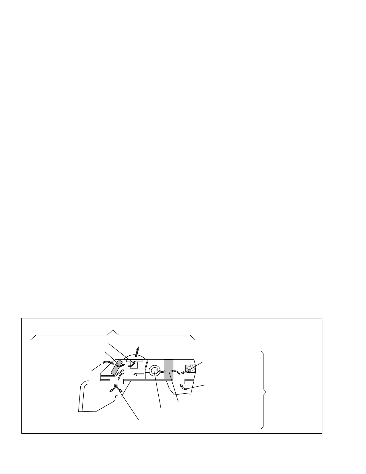
1.9 HEATING CYCLE
Heating circuit (Figure 1-7) components furnished by
Carrier Transicold include the integral evaporator coil
heater cores and a solenoid operated heat valve.
Componentsfurnishedby the bus manufacturerinclude
auxiliary heater and boost water pump. The controller
automaticallycontrols theheat valveduring theheating
and reheat modes to maintain required temperatures
HEAT
VALVE
BOOST
PUMP
MAIN ENGINE
RADIATOR
COMPRESSOR
inside the bus. Engine coolant (glycol solution) is
circulatedthrough the heating circuitby the engine and
an auxiliary boost water pump. When the heat valve
solenoid i s energized, the valve will open to allow
enginecoolanttoflowthrough theheatercoil. Thevalve
is normally closed so that if a failureoccurs, the system
will be able to cool.
T--295
1-8
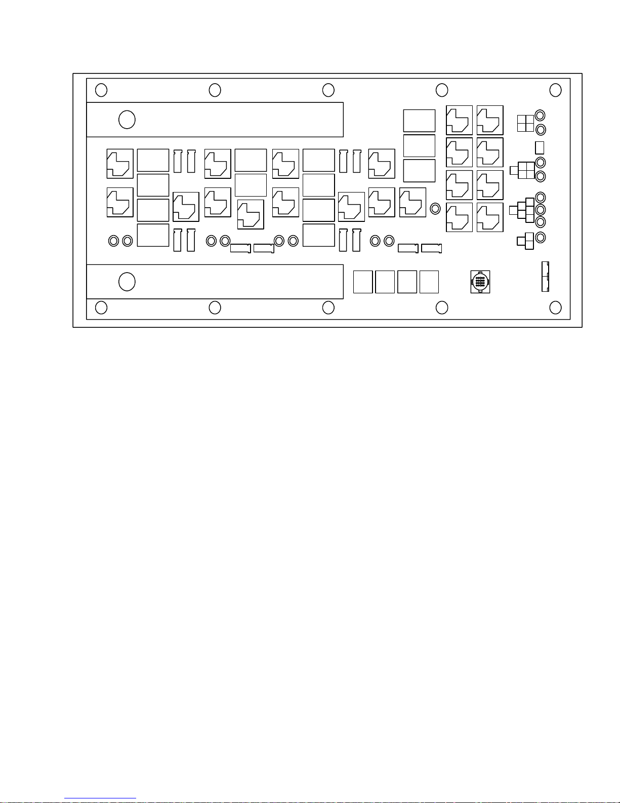
1.10 RELAY BOARD
1.10.1 Permanent Magnet Motors with 2 speed switching from series to parallel connection (Option 1)
JP6
K1
K2
D2 D6
CB 1
CB 2
CB 3
CB 4
EF1
EF2
K5
EF4EF3
D14
K3
K4
D17
EF6
CB 5
CB 6
K6
D26 D30
EF5
K7
K8
CB 7
CB 8
CB 9
CB 10
CF1
CF3
CF2
K11
CF4
K9
K10
D38 D41
K22K24
CB 13
CB 11
CB 12
K12
CF6 CF5
K23K21
K15K14
K17K16
K20K18
D85
K13K19
JP1
1
D57
3
4
2
D54
JP5
4
23
1
1
D63
5
D60
JP4
D72
4
2
5 6
D66
3
D51
JP3
23
1
D69
JP2
Figure 1-8 Relay Board (Option 1)
a. Relays
K1 Energizes evaporator fans 1 & 2 in high speed
or evaporator fans 1,2,3 & 4 in low speed.
K2 Energizes evaporator fans 3 & 4 in high speed
(not energized in low speed).
K3 Energizes evaporator fan 5 in high speed or
evaporator fans 5 & 6 in low speed.
K4 Energizes evaporator fan 6 in high speed (not
energized in low speed).
K5 Connects the negative side of evaporator fans
1 & 2 to ground in high speed. Connects the
negative side of evaporator fans 1 & 2 to
positive side of evaporator fans 3 & 4 in
low speed
K6 Connects the negative side of evaporator fan
5 to ground in high speed. Connects the
negative side of evaporator fan 5 to
positive side of evaporator fan 6 in
low speed
K 7 Energizes condenser fans 1 & 2 in high speed
or condenser fans 1,2,3 & 4 in low speed
K 8 Energizes condenser fans 3 & 4 in high speed
(not energized in low speed).
K 9 Energizes condenser fan 5 in high speed or
condenser fans 5 & 6 in low speed.
K10 Energizes condenser fan 6 in high speed
(not energized in low speed).
K11 Connects the negative side of condenser fans
1 & 2 to ground in high speed. Connects the
negative side of condenser fans 1 & 2 to
the positive side of condenser fans 3 & 4 in
low speed.
K12 Connects the negative side of condenser fan
5 to ground in high speed. Connects the
negative side of condenser fan 5 to
the positive side of condenser fan 6 in
low speed.
K13 Energizes the A/C clutch.
K14 Energizes unloader 1.
K15 Energizes unloader 2.
K16 Energizes the fresh air damper.
K17 Energizes the heat valve.
K18 Energizes the fault light output.
K19 Energizes the Boost Pump.
K20 Energizes the spare output.
K21 Is energized by the logic board to turn the
evaporator fans on high. The contacts of this
relay energize the coils of relays K1, K2,
K3 & K4.
K22 Is energized by the logic board to turn the
evaporator fans on low. The contacts of this
relay energize the coils of relays K1, K3,
K5 & K6.
K23 Is energized by the logic board to turn the
condenser fans on high. The contacts of this
relay energize the coils of relays K7, K8,
K9 & K10.
K24 Is energized by the logic board to turn the
condenser fans on low. The contacts of this
relay energize the coils of relays K7, K9,
K11 & K12.
1-9
T--295

b. Thermal Circuit Breakers
CB 1 Evaporator Fan #1. 15 Amp.
CB 2 Evaporator Fan #2. 15 Amp.
CB 3 Evaporator Fan #3. 15 Amp.
CB 4 Evaporator Fan #4. 15 Amp.
CB 5 Evaporator Fan #5. 15 Amp.
CB 6 Evaporator Fan #6. 15 Amp.
CB 7 Condenser Fan #1. 15 Amp.
CB 8 Condenser Fan #2. 15 Amp.
CB 9 Condenser Fan #3. 15 Amp.
CB10 Condenser Fan #4. 15 Amp.
CB11 Condenser Fan #5. 15 Amp.
CB12 Condenser Fan #6. 15 Amp.
CB13 A/C clutch, Unloaders 1&2,
Fresh Air Damper, Heat Valve,
Fault Output and Spare
output. 15 Amp
c. Connectors
EF1-EF6 Evaporator fans.
CF1-CF4 Condenser fans.
JP1 External evaporator & condenser fan
thermal overload connections.
JP2 Logic board connector.
JP3 Boost pump.
JP4 A/C clutch, fault output, compressor high
pressure switch.
JP5 Spare output, fresh air output, heat valve.
JP6 Unloaders 1 & 2.
d. LEDS
D 2 Relay K1 output active (evaporator fans 1,2,3 &
4 energized)
D 6 Will be brightly lit if evaporator fans 1, 2, 3 & 4
are on high. Will be at half intensity of they are on low.
D14 Relay K3 output active (evaporator fans 5 & 6
energized).
D17 .Will be brightly lit if evaporator fans 5 &6 are
on high. Will be at half intensity of they are on low.
D26 Relay K7 output active (condenser fans 1, 2, 3
& 4 energized).
D30 Will be brightly lit if condenser fans 1, 2, 3 & 4
are on high. Will be at half intensity of they are on low.
D38 Relay K9 output active (condenser fans 5 & 6
energized).
D41 Will be brightly lit if condenser fans 5 &6 are on
high. Will be at half intensity of they are on low.
D51 A/C clutch output active.
D54 Unloader 1 output active.
D57 Unloader 2 output active.
D60 Fresh air output active.
D63 Heat valve output active.
D66 Fault output active.
D69 Boost pump output active.
D72 Spare output active.
T--295
1-10

1.10.2 Electronically Communtated DC Motors with 2--speed Evaporator Input Signal (Option 2)
JP6
1
K1
K2
D2 D6
CB 1
CB 2
CB 3
CB 4
EF1
EF3
EF2
EF4
K5
K3
K4
K14
K16
K18
K20
K15
K17
K19
K13
JP1
CB 13
CB 11
K9
CF1
CF3
K11
CF2
CF4
K24
K10
D41D38
K22
CB 12
D85
CF HIGH SIGNAL
CF6 CF5
K23K21
K7
K8
D30
CB 7
CB 8
CB 9
CB 10
CB 5
CB 6
D81
D17D14
EF HIGH SIGNAL
EF6 EF5
D26
1
1
2
JP5
JP4
23
JP3
1
3
4
4
2
5
3
4
5 6
2
3
JP2
D57
D54
D63
D60
D72
D66
D51
D69
Figure 1-9 Relay Board (Option 2)
a Relays
K1 Energizes evaporator fans 1 & 2
K2 Energizes evaporator fans 3 & 4.
K3 Energizes evaporator fan 5.
K4 Energizes evaporator fan 6.
K5 Provides evaporator fan high output signal.
(Motors are in low speed when K5
is de--energized)
K6 Not Used
K 7 Energizes condenser fans 1 & 2.
K 8 Energizes condenser fans 3 & 4.
K 9 Energizes condenser fan 5
K10 Energizes condenser fan 6.
K13 Energizes the A/C clutch.
K14 Energizes unloader 1.
K15 Energizes unloader 2.
K16 Energizes the fresh air damper.
K17 Energizes the heat .
K18 Energizes the fault light output.
K19 Energizes the Boost Pump.
K20 Energizes the spare output.
K21 or K22 Is energized by the logic board to
turn the evaporator fans on. The contacts
of these relays energize the coils of relays K1,
K2, K3 & K4.
K23 or K24 Is energized by the logic board to
turn the condenser fans on high. The contacts
of these relays energize the coils of relays K7,
K8, K9 & K10.
b Thermal Circuit Breakers
Refer to paragraph 1.10.1b.
c. Connectors
Refer to paragraph 1.10.1c.
EF HIGH SIGNAL Output to the evaporator fans
to operate on high.
CF HIGH SIGNAL Output to the condenser fans
to operate on high.
d. LEDS
Refer to paragraph 1.10.1d.
D81 Evaporator fans on high
D85 Condenser fans on high
1-11
T--295

1.11 LOGIC BOARD
J1 Logic board power in.
J2 Display interface.
J3 Manual control inputs.
J4 Interlock Inputs
(WTS, low side pressure switch etc.)
J5 Relay board interface.
J6 Sensor inputs (Thermistors, etc.).
T--295
J7 Diagnostics interface (RS232, DB9).
D2 Blinks once per second in normal operation.
On steady to indicate alarms detected.
D3 Off In normal operation, blinks out alarm
codes (2 digits each) when alarms detected.
A-P Configuration Jumpers
Figure 1-10 Logic Board
1-12

1.12 CONTROL PANEL (Diagnostic Module)
123 4 5 6
7
1. Display
2. DOWN Button -- decrease selection
3. UP Button -- increase selection
4. VENT (Only) Button
5. AUTO Button (Automatic Control)
6. COOLING (Only) Button
Figure 1-11. Micromate Control Panel
91011
8
7. HEAT (Only) Button
8. FAN SPEED Button
9. FRESH AIR Button
10. TEMPERATURE ( Inside / Outside)
Button
11. ON/OFF Button
1-13
T--295

SECTION 2
OPERATION
2.1 STARTING, STOPPING AND OPERATING
INSTRUCTIONS
2.1.1 Power to Logic Board
Before starting, electricalpower must beavailable from
the bus power supply. The system components receive
power from two sources:
a. 24 vdc power for the microprocessor electronics is
supplied through the bus multiplex module.
b. 24 vdc, 125 amp, power from a fuse in the battery
compartment supplies power for the, clutch, compressor unloader solenoids, evaporator and condenser assemblies; this power is controlled by the Logic
Board.
2.1.2 Starting
a. If the engine is not running, start the engine.
b. OEM SUPPLIED SWITCHES
Actual start sequence depends on the operating controlssupplied.If only an ON/OFF switch issupplied,
placethe switch in the ON position to start thesystem
in the automatic mode. If additional OEM switches
are supplied, refer to the following Micromate control description for operating instructions.
c. MICROMATE CONTROL PANEL
It is suggested the system be started in the automatic
mode.
1 The Micromate Control Panel Display (see
Figure 1-11) may be programmed to display the set
pointtemperatureor returnairtemperature.Todetermine which display temperature is programmed,
press the TEMPERATURE button so that the OUT
SIDE AIR indicator is illuminated. If the controller
cycles back to the INSIDE AIR indicator, than the
controller is programmed to display return air temperature. If the controller does not automatically
cycle back to the return air indicator, than the controller is programmed to display set point temperature.
2 Tostartthesystem,pressthe I/Obutton to illuminate
theindicatorlight and signal the Logic Board to perform start up. Ensure the AUTO button indicator is
illuminated. If not, press the AUTO button to place
the system in the automatic mode. Afterthe pre--trip
inspection is completed, the switches may be set in
accordance with the desired control modes.
3 If cooling only, heating only or ventilation only is
desired, press the corresponding button (refer to
Figure 1-11) to illuminate the indicator light and
place the system in that mode of operation.
4 Iflow or high speedevaporatorfan speed is desired,
press the FAN SPEED button to illuminate the indicator light and bring speed to the desired level.
5 To open or close the fresh air damper, press the
FRESH AIR button to illuminate the indicator light
and bring the damper to the desired position.
6 To read interior or exterior temperature, press the
TEMPERATUREbutton to illuminate the indicator
lightandbringthedisplayto the desiredtemperature
reading.After a short delay,thedisplaywillreturnto
the default set point or return air temperature reading.
7 Setpoint may be changed by pressing the UP or
DOWN arrow button. The UP button will increase
the setpoint temperatureand the DOWN button will
decrease the setpoint temperature.
8 For additional Micromate operating data refer to
paragraph 2.4.
2.1.3 Self-Test and Diagnostics (Check for Errors
and/or Alarms)
Self-test of the main Logic Board electrical circuit is
automaticallyinitiated when the system is powered up.
If there is an error in the circuit, an alarm will be
indicated by flashing LED’s on the Logic Board. If a
Micromate is connected to the Logic Board, the error
codecanalso be read on thedisplay. If there are no errors
inthecircuit,system will operatenormally andflashthe
status LED at a one second interval. During normal
operation, the Logic Board monitors system operating
parameters for out of tolerance conditions. If an out of
tolerance condition occurs, ALARM will be indicated
through the code LED or on the Micromate display.
Refer to section 3 for definition of system errors and
alarms and general troubleshooting procedures.
2.1.4 Stopping
Placing the ON/OFF switch in the OFF position or
pressing the Micromate ON/OFF button will stop the
system operation by removing power to the Logic
Board.
2.2 PRE--TRIP INSPECTION
Afterstartingsystem, allowsystemto stabilizefor tento
fifteen minutes and check for the following:
a. Listen for abnormalnoises in compressor or fan mo-
tors.
b. Checkcompressoroil level. (Refer to section 4.20.3)
c. Check refrigerant charge. (Refer to section 4.8.1 )
d. Ensure that self-test has been successfullyperformed
andthat there are noerrors oralarms indicated. (Refer
to section 2.1.3.)
2-1
T--295

AUTO MODE REHEAT
AUTO MODE CYCLE
HEAT MODE
3°F
2°F
1°F
SETPOINT
-- 1 °F
-- 2 °F
-- 3 °F
COOL
HIGH SPEED
LOADED
COOL
HIGH SPEED
4 CYLINDERS
COOL
LOW SPEED
2 CYLINDERS
REHEAT 100%
DUTY CYCLE
LOW SPEED
4 CYLINDERS
3°F
2°F
1°F
SETPOINT
-- 1 °F
-- 2 °F
-- 3 °F
COOL
HIGH SPEED
LOADED
COOL
HIGH SPEED
4 CYLINDERS
COOL
LOW SPEED
2 CYLINDERS
VENT
HEAT
2°F
1°F
SETPOINT
VENT
-- 1 °F
-- 2 °F
HEAT
-- 3 °F
-- 4 °F
3°F
2°F
1°F
SETPOINT
-- 1 °F
HEAT
COOLING MODE COOLING MODE
REHEAT
COOL
HIGH SPEED
LOADED
COOL
HIGH SPEED
4 CYLINDERS
COOL
LOW SPEED
2 CYLINDERS
REHEAT 100%
DUTY CYCLE
LOW SPEED
4 CYLINDERS
3°F
2°F
1°F
SETPOINT
-- 1 °F
CYCLE
COOL
HIGH SPEED
LOADED
COOL
HIGH SPEED
4 CYLINDERS
COOL
LOW SPEED
2 CYLINDERS
VENT
-- 2 °F
Figure 2-1 Capacity Control Diagram
T--295
-- 2 °F
2-2

2.3 MODES OF OPERATION
The system is operated by a Carrier Transicold
Micromax microprocessor controllerwhich consists of
a logic board (Figure 1-10), relay board (Figure 1-8 or
Figure 1-9), and manual operator switches. The logic
board regulates operational cycles of the system by
energizing or de--energizing Relay Board relays in
responsetodeviationsin interiortemperature.Modes of
operation include Cooling, Heat and Vent. Refer
toFigure 2-1 and the following paragraphs for a
description of each mode.
Figure 2-1 shows the Logic Board actions at various
temperature deviations from setpoint. On rising
temperature, changes occur when the temperature rises
above Logic Board setpoints, On falling temperature,
changes occur when temperatures falls below Logic
Boardsetpoint. The system will operatein thesemodes
unless pressures override the Logic Board settings.
2.3.1 T emperature Control
Temperature is controlledby maintaining the return air
temperature measured at the return air grille.
2.3.2 Cooling Mode
Coolingis accomplished by energizing the compressor
and condenser fans, opening the liquid line solenoid
valve and closing the heating valve. Once interior
temperature reaches the desired set point, the system
may operate in the clutch cycle or reheat mode.
Selection of clutch cycle or reheat is factory
programmed in accordance with the bus purchase
specification.
A controller programmed for clutch cycle will
de--energizethecompressorclutchandallowthesystem
to operate in the vent mode until further cooling is
required.
A controller programmed for reheat will maintain
compressor operation and cycle the heat valve to allow
reheating of the return air. In the reheat mode interior
temperatureis maintained at the desired set point while
additional dehumidification takes place.
2.3.3 Heating Mode
In the heat mode the liquid line solenoid is closed and
the compressor and condenser fans are shut down. The
heat valve is opened to allow a flow of engine coolant
through the heat section of the evaporator coil. The
evaporator fans speed is varied as required to circulate
air over the evaporator coil based on the temperature
difference from setpoint.
Heatingwill not startuntil thewatertemperatureswitch
(WTS) closes. The WTS is located on the block of the
vehicleandisprovidedby theOEM. Itsensestheengine
coolant temperature and closes on temperature rise at
105F . Theswitch preventsthe circulationof cooler air
throughout the vehicle as the engine comes up to
temperature.
2.3.4 Boost Pump
When the unit is in heat the boost pump relay is
energized, providing 24 VDC to activate the boost
pump.
2.3.5 Vent Mode
In the vent mode the evaporator fans are operated to
circulate air in the bus interior.
2.3.6 Fresh Air System
The fresh air damper is opened to allow entrance of
ambientair into theairenteringtheevaporatorcoil. The
damperisoperatedby thecontrollertoopenwhenreturn
airt emperatureiswithin+/--5F (+/--2.8C)of setpoint.
2.3.7 Compressor Unloader Control
When operating in cooling, the unloaders are used to
reduce system capacity as return air temperature
approaches set point. Operation of the unloaders
balances system capacity with the load and thereby
prevents overshoot from set point.
Relay Board mounted unloader outputs control the
capacity of the compressor by energizing or
de-energizing unloader solenoid valves. The model
05K (GR45)has two banks of twocylinders each while
the model 05G compressor (GR60) has three banks of
two cylinders each. Energizing a valve de-activates a
bankofcylinders.The05K right cylinder bank(looking
at the pump end) and theoutboardcylinderbanks of the
05G are equipped with unloader valves (UV1 and, for
the 05G, UV2), each controlling two cylinders; this
allowsthe05Ktobeoperatedwithtwoorfourcylinders
and the 05G to be operated with two, four or six
cylinders.
Whenever the compressor is started, the unloaders are
energized for thirty seconds to reduce starting torque.
After thirty seconds, unloaders may be de-energized.
Any subsequent changes between energizing and
de-energizing the unloaders for temperature control
must be staged with a thirty second delay. Once an
unloader is energized for pressure control, it remains
energized for two seconds to prevent short cycling.
Only one unloader may change state at a time when
staging is required. Operating parameters for
temperature control, suction pressure control and
discharge pressure control are as follows.
a. Temperature Control
The unloaders are used to control system capacity by
controlling compressor capacity.
1 Compressor Unloader UV1 Relay.
When return air
temperature falls to less than 2F (1.1C) above set
point unloader UV1 is energized. If temperature
rises to greater than 3F (1.7C) above set point,
UV--1 will be de--energized to place the compressor
at 100% capacity.
2 Compressor Unloader UV2 Relay. When return air
temperature falls to less than 1F (0.6C) above set
point unloader UV2 is energized. If temperature
rises to greater than 2F (1.1C) above set point,
UV--2 will be de--energized to place the compressor
(GR60 only) at 66% capacity.
b. Suction Pressure
2-3
T--295

The unloaders are used to control suction pressure and
thereby prevent coil frosting:
1 CompressorUnloaderUV1Relay.
Whenthe suction
pressuredecreasesbelow26 psig (1.77 bar),unloader UV1 is energizedunloading a cylinder bank (two
cylinders); this output will remain energized until
the pressure increases to above 34 psig (2.31 bar).
2 Compressor Unloader UV2 Relay.
When suction
pressure decreases below 23 psig (1.56 bar) [on a
GR60], unloader UV2 is energized unloading the
second compressor cylinder bank; this output will
remain energized until the pressure increases to
above 31 psig (2.11 bar).
c. Discharge Pressure
Dischargepressure is also controlled by the unloaders:
1 Compressor Unloader UV1 Relay.
When the discharge pressure increases above 275 psig (18.71
bar), unloader UV1 is energized; this output will remain energized until the pressure decreases below
220 psig (14.97 bar). Staging is ignored during discharge pressure override.
2 Compressor Unloader UV2 Relay.
When the discharge pressure increases above 285 psig (19.39
bar),unloader UV2 is energized; this output will remain energized until the pressure decreases below
225 psig(15.31 bar).
2.3.8 Evaporator Fan Speed Selection
Temperature control is the primary method of
determining the fan speed selection. The following
table indicates relay operational status for the various
fanmotorstates while Figure 2-1provides Logic Board
speed selections at various deviations form set point..
Table 2-1. Evaporator Fan Speed Relay Operation
STATE
HIGH
SPEED
RELA YS
EVAP FAN
RELA Y
Off Off Off
Low Off On
High On On
2.3.9 Condenser Fan Control
The condenser fans are energized when the compressor
clutch output is energized. The fans are started in low
speed and will remain in low speed until the discharge
pressureincreases to 225 psig(15.31 bar). The fanswill
remainin high speed until dischargepressuredecreases
below 190 psig (12.93 bar). The fans will also be
activated if a highpressure alarmhas been activated and
operation has not been locked out (refer to Table 3-3).
2.3.10 Compressor Clutch Control
A belt driven electric clutch is employed to t ransmit
engine power to the air conditioning compressor.
De-energizing the clutch electric coil disengages the
clutch and removes power from the compressor. The
clutch will be engaged when in cooling and disengaged
whenthesystemisoff,inheatingor duringhighandlow
pressure conditions.
The clutch coil is prevented from engagement when the
ambient temperature is below 45F (7.2C).
The clutch coil will be de-energized if the discharge
pressure rises to the 300 psig (20.41 bar) cutout setting
of the compressor mounted high pressure switch. The
clutch coil will energize when the discharge pressure
falls to 200 psig (13.61 bar).
The clutch coil will be de-energized if the suction
pressure decreases below 10 psig (0.68 bar).
2.3.11 Alarm Description
Alarm descriptions and troubleshooting procedures are
provided in section 3.
2.3.12 Hour Meters
Hourmeterreadings are available in the parametercode
list of the Micromate. The hour meters record the
compressor run time and the total time the evaporator
fans are on. The maximum hours is 999,999. Refer to
paragraph 2.4.3 for instructions on reading parameter
codes.
2.4 MICROPROCESSOR DIAGNOSTICS
The Micromate allows the user to interface with the
microprocessor based control. This allows system
parameters, alarms and settings to be viewed and
modified. On systems with OEM supplied operating
switches, a Micromate may be connected as a service
tool using a special harness. The following instructions
supplement those provided in paragraph 2.1.2. Once a
Micromate is connected as a service tool, the following
instructions are applicable.
2.4.1 Connecting
Connect the Micromate harness to the service port
locatedinthereturnairsectionoftheA/C system.When
the Micromate is connected, the panel lights will be
energized and the currently stored setpoint will be
displayed. If any alarm is active, the reading will be
A##, where A indicates that the alarm is active and ##
indicates the alarm number.
T--295
2-4

2.4.2 Control
NOTE
1 This procedure should be performed by an
HVAC technician who has been trained on
Carrier Model GR system design. Control
configuration is preset by the manufacturer
and resetting of the parameters should not
berequired.ItisrecommendedthatCarrier
Service or Engineering is contacted before
any control configuration is changed.
Carriercannot beresponsibleforfailuresor
damage resulting from unauthorized
changes.
2 If a replacement LogicModule is installed,
it is necessary to match the configuration
jumpers (see Figure 1-10) to the original
board. Refer to paragraph 4.24.
a. Turnthe A/C main power switch (located in thedriv-
er’s area) to OFF.
b. Connect the Micromateto the serviceport located in
the return air section.
c. Unplug the logic board connector J3.
d. Turn theA/Cmain powerswitchback to the ONposi-
tion.
e. Activate the system by pressing the 1/0 key on the
Micromate panel.
NOTE
Be sure to reconnect J3 when testing is completed or the system will fail to operate when
the Micromate is disconnected.
NOTE
When modifying the setpoint temperature for
diagnostic purposes, be sure to reset the setpoint when testing is complete.
2.4.3 Diagnostic Mode
Diagnostic mode can be entered by pressing the up and
down arrow keys simultaneously for 5 seconds.
Diagnostic mode allows alarms and system parameters
to be viewed. If there are any alarms stored, the most
recent alarm will be shown. To view additional alarm
information, refer to section 3. Press the up and down
arrow keys to view parameters.
2.4.4 System Parameters
Pressing the up/down arrow keys will allow the user to
scroll up or down through the parameters. If no key is
pressed for 30 seconds this mode is exited and the
display will revert back to the default display.Pressing
the on/off key any time will exit this mode and the
display will again indicate the default. The parameters
are shown in Table 2-3. When scrolling through the
parameters, the current parameter will be displayed for
two seconds. After two seconds, the display will show
the data for the current parameter. When the last
parameter is reached, the list will wrap back to P1.
2.4.5 T est Mode
Withthe system in normal operation,thecontrollermay
be placed in the test mode, by doing the following:
a. Enter the diagnostic mode by pressing the up and
downarrow keyssimultaneouslyfor5 seconds. Enter
the test mode by pressing the COOL key five times.
b. In the test mode, the display will read “T##” where
“##” indicated the test number t hat is currently running.
c. The initial indication will be “T00”. This indicates
thecontrolleris in thetestmodeand all relays arede-energized. Press the arrow keys to scroll through and
perform each test When the highest test number is
reached, thedisplaywill increment back tothelowest
test number. A listing of tests is provided in
Table 2-2.
d. To terminate testing, press the I/0 key.
Table 2-2. Controller Test List
TEST
OUTPUT STATE
T00 All Relays Off
T01 Evaporator High On
T02 Evaporator Low On
T03 Condenser High On
T04 Condenser Low On
T05 Compressor On
T06 Unloader Valve 1 On
T07 Unloader Valve 2 On
T08 Fresh Air Damper On
T09 Heat On
T10 Fault On
T11 Boost On
T12 Spare/Motor Input On
2-5
T--295

Table 2-3. Parameter Codes
CODE
P1 Return Air
CODE NAME DESCRIPTION
This value is the temperature measured by the return air sensor. If the sensor is
Temperature
shorted it will display CL. If it is open circuited it will display OP.
P2 Coil Temperature This value is the coil temperature measured by the evaporator temperature sen-
sor. If the sensor is shorted it will display CL. If it is open circuited it will display OP.
P3 Ambient Temperature This value is the outside temperature measured by the ambient temperature
sensor. If the sensor is shorted it will display CL. If it is open circuited it will
display OP.
P4 Suction Line Temper-
Not used.
ature
P5 Suction Pressure This value is the suction pressure measured by the suction pressure transducer.
If the sensor is shorted it will display CL If it is open circuited it will display
OP.
P6 Discharge Pressure This value is the discharge pressure measured by the discharge pressure trans-
ducer. If the sensor is shorted it will display “CL” and if it is open circuited it
will display “OP”.
P7 Superheat Not used.
P8 Analog Set Point
Not used.
Temperature
P9 A/C Control Window#1This is the number of degrees F above setpoint at which the unloaders will be
both energized. This value can be modified between 0 and 10 degrees F. The
default value is 1 degree F.
P10 A/C Control Window#2This is the number of degrees F above AC control window one at which the
first unloader will be energized. This value can be modified between 0 and 10
degrees F. The default value is 1 degree F.
P11 A/C Control Window#3This is the number of degrees F above AC control window two at which the
evaporator fan speed will be set to low. This value can be modified between 0
and 10 degrees F . The default value is 1 degree F .
P12 Heat Control Window This is the number of degrees F below setpoint before the heat valve is energi-
zed. This value can be modified between 0 and 10 degrees F. The default value
is 2 degree F for heat and 4 degrees F for reheat.
P13 Compressor Safety
Off Delay
This number is the minimum time in minutes that the compressor must be off
after a high or low pressure alarm before it can be restarted. This value can be
modified between one and five minutes. The default value is 1.
P14 Fan Delay This is the minimum time (in seconds) that the fans must run at a particular
speed before changing to another speed. This value can be modified between
one and 60 seconds. The default value is two seconds.
P15 Unloader/Heat Valve
Delay
This is the minimum time (in seconds) that the unloaders and heat valve must
be in a particular state (open /closed) before changing to another state. This
value can be modified between 1 and 60 seconds. The default value is 2 sec-
onds.
P16 Compressor High
Pressure Switch
P17 Condenser Fan Speed
This is the current state of the compressor high pressure switch input. “CL”
will be displayed i f it is closed and “OP” will be displayed if it is open.
Not used.
Switch
T--295
2-6

Table 2-3. Parameter Codes -- Continued
Code
Code Name Description
P18 Maximum Setpoint This is the maximum value that the operator will be allowed to set the setpoint
temperature. The value can be modified in degrees with the up and down keys
to a value between 60F and 80F.
P19 Minimum Setpoint This is the minimum value that the operator will be allowed to set the setpoint
temperature. The value can be modified in degrees with the up and down keys
to a value between 60F and 80F.
P20 Compressor Hours
High
P21 Compressor Hours
Low
P22 Evaporator Hours
High
P23 Evaporator Hours
Low
P24 Maintenance 1 Hour
High
This is the number of hours of operation that the compressor has run with the
clutch energized in thousands
This is the number of hours of operation that the compressor has run with the
clutch energized in hundreds, tens and ones.
This is the number (in thousands) of hours of operation with the evaporator
fans energized.
This is the number (in hundreds, tens and ones) of hours of operation with the
evaporator fans energized.
This is the value of compressor hours high (P20) at which maintenance alarm
#1 will be activated. This value can be modified by the up and down arrow
keys. If both high and low values are zero the alarm is disabled.
P25 Maintenance 1 Hour
Low
This is the value of compressor hours low (P21) at which maintenance alarm
#1 will be activated. This value can be modified by the up and down arrow
keys. If both high and low values are zero the alarm is disabled.
P26 Maintenance 2 Hours
High
This is the value of evaporator fan hours high (P22) at which maintenance
alarm #2 will be activated. This value can be modified by the up and down arrow keys. If both high and low values are zero the alarm is disabled.
P27 Maintenance 2 Hours
Low
This is the value of evaporator fan hours low (P23) at which maintenance alarm
#2 will be activated. This value can be modified by the up and down arrow
keys. If both high and low values are zero the alarm is disabled.
P28 Freeze Alarm Setting This is the value at which the freeze alarm will be activated. The default value
is 32F. This value can be modified between 20F and 40F in one degree in-
crements by using the arrow keys
P29 Relay Module Voltage This is the voltage being supplied to the relay module.
P30 Main Board Software
This is the software version of the logic board.
Version
P31 Display Software
This is the software version of the display module.
Version
P32 Ki Not used.
P33 Kp Not used.
P34 Default Display This is the value displayed on the Micromate control panel. It is set to OFF to
display set point temperature or set to ON to display return air temperature.
This feature is available in software revision 1.9 and later.
P33
Not Defined Not used. These codes will show in software revision 1.9 and later.
to
P34
2-7
T--295

SECTION 3
TROUBLESHOOTING
CAUTION
Donot under anycircumstancesattempt toservicethemicroprocessor. should aproblem developwith
the microprocessor, replace it.
3.1 SELF DIAGNOSTICS
errorcodes can be read by counting thenumber of times
that the Logic Board STATUS and CODE LED’s (see
A self test is performed by the Micromax Logic Board
each time the boardis poweredup.Errors,ifany,willbe
indicated and the unit will not be allowed to start. The
Table 3-1 Error Codes
CODE
NAME DESCRIPTION
Figure 1-10) flash simultaneously. The Micromate
display will indicate errors with the code ER-#, where
“ER” is the error prefix and # is the error number.
ER 1 Data Memory Logic board data memory failure.
ER 2 Program Memory Logic board program memory failure.
ER 3 A/D A/D and multiplexer failure.
ER 4 Communication Failure Failure in communication between the logic board and MDST.
ER 5 Program Memory Display program memory failure.
3.2 SYSTEM ALARMS
3.2.2 Activation
When alarms are detected, they are placed in an alarm
3.2.1 Alarm Codes
queue in the order at which they initiated unless the
alarm is already present. Each alarm recorded will also
captureanevaporatorhourmeterreadingcorresponding
The Micromax Logic Board continuously monitors
system parameters and will generate an ALARM if a
parameter exceeds preset limits. Alarms are indicated
and the controller will respond in accordance with the
informationprovided in Table 3-2.Thealarmcodescan
be read by counting the number of times that the Logic
Board CODE LED (see Figure 1-10) flashes. Each
alarm code is a two digit number,the first set of flashes
is the first digit and (after a slight pause) the second set
of flashes is the second digit. The Micromate display
will indicate alarms with the code A-## or i--##, where
“A” is an active alarm prefix, “i” is an inactive alarm
prefixand ## is the errornumber. If multiple alarmsare
present the user can scroll through each alarm by
pressing the ARROW keys. When the end of the alarm
list is reached the display will show “------”. If the auto
key is held down for five seconds while “------” is
displayed all inactive alarms are cleared. A listing of
alarm codes is provided in Table 3-2.
to the activation time. If the AUTO key is pressedwhile
analarmisdisplayed,the activationtimecapturewillbe
shown.
3.2.3 Alarm Queue
The alarm queue consist of 10 alarm locations. When
the alarm queue is full the Logic Board will take the
requiredactionbut the alarmwill not be recorded.When
this situation occurs, an “AlarmQueue Full”alarm will
be generated. When the alarms are viewed this will be
the first alarm to be shown.
3.2.4 Alarm Clear
Theuser may clearinactivealarmsusingtheMicromate
keypad. Refer to paragraph 3.2.1.
3.3 TROUBLESHOOTING
General procedures for system troubleshooting are
provided in Table 3-3
T-295
3-1

Table 3-2 Alarm Codes
ALARM
NO.
TITLE CAUSE REMEDY CONTROLLER
A11 Coil Freeze Coil temperature is
less than 32F and the
compressor is operating.
A12 High Voltage The battery voltage is
greater than 32 volts.
A13 Low Voltage The battery voltage is
less than 17 volts.
A14 Return Air Probe Failure Return air temperature
sensor failure or wiring defective.
A15 Suction Pressure
Transducer Failure
Suction pressure
transducer failure or
wiring defective.
A16 Discharge Pressure
Transducer Failure
Discharge pressure
transducer failure or
wiring defective.
A17 Low Pressure Shutdown Low suction pressure
switch open or wiring
defective.
A21 High Discharge Pressure High discharge pres-
sure switch open or
wiring defective.
Check causes of coil
freezing. (Refer to
section 3.3.6)
Check, repair or replace alternator.
Check, repair or replace wiring or alternator.
Ensure all connectors
are plugged in. Check
sensor resistance or
wiring. Refer to paragraph 4.21. Replace
sensor or repair wiring.
Ensure all connectors
are plugged in. Check
sensor voltage or wiring. Replace sensor or
repair wiring.
Ensure all connectors
are plugged in. Check
sensor voltage or wiring. Replace sensor or
repair wiring.
Check cause of low
suction pressure. (Refertosection3.5.3)
Check discharge pressure transducer reading, wiring or cause of
high discharge pressure. (Refer to section
3.3.3)
RESPONSE
An alarm will be generated and the system will
shutdown. The evaporator fans will remain running while the compressor is off.
The system is shut down
until the voltage returns
to normal levels.
The system is shut down
until the voltage returns
to normal levels.
All outputs except the
evaporator fans will be
de-energized.
Both unloaders are energized.
One unloader is energized.
The clutch is de-energized for the minimum
off time. The evaporator
fans will remain running
during this period. After
the compressor cycles
off three times in 30
minutes all outputs will
be de-energized and the
system is locked out until the power is cycled or
the alarm is reset.
The clutch is de-energized for the minimum
off time. The condenser
and evaporator fans will
remain running during
this period. After the
compressor cycles off
three times in 30 minutes all outputs will be
de-energized and the
system is locked out until the power is cycled or
the alarm is reset.
3-2
T--295

Table 3-2 Alarm Codes -- Continued
ALARM
NO
TITLE CAUSE REMEDY CONTROLLER
A22 Breaker Trip Alarm A breaker on the relay
board has tripped or a
fan relay has failed.
A23 Evaporator Fan Overload Evaporator fan over-
load jumper is open.
A24 Condenser Fan Overload Condenser fan over-
load jumper is open.
A25 Motor Failure A brushless motor has
not reached full operating speed or a motor
failure.
A26 Not used
A31 Maintenance Alarm 1 The compressor hour
meter is greater than
the value in Mainte-
nance Hour Meter 1.
A32 Maintenance Alarm 2 The evaporator hour
meter is greater than
the value in Mainte-
nance Hour Meter 2.
Check breakers for
tripped device. Repair
short and reset breaker .
Ensure connector is
plugged in or repair
wiring.
Ensure connector is
plugged in or repair
wiring.
Replace motor, or correct pressure shutdown.
Reset the maintenance
hour meter.
Reset the maintenance
hour meter.
RESPONSE
Alarm will be generated.
Alarm will be generated.
Alarm will be generated.
Alarm displayed and the
motor fail output is energized.
Alarm will be generated.
Alarm will be generated.
A99 Alarm Queue Full All locations of the
alarm queue are cur-
rently full and no
more alarms can be
saved.
Record and clear
alarm queue.
Alarm will be generated.
T-295
3-3

Table 3-3 General System Troubleshooting Procedures
INDICATION/
TROUBLE
3.3.1 System Will Not Cool
POSSIBLE CAUSES
Compressor will not run Active system alarm
V-Belt loose or defective
Clutch coil defective
Clutch malfunction
Compressor malfunction
Electrical malfunction Coach power source defective
Circuit Breaker/safety device open
3.3.2 System Runs But Has Insufficient Cooling
Compressor V-Belt loose or defective
Compressor valves defective
Refrigeration system Abnormal pressures
No or restricted evaporator air flow
Expansion valve malfunction
Restricted refrigerant flow
Low refrigerant charge
Service valves partially closed
Safety device open
Liquid solenoid valve stuck closed
REFERENCE
SECTION
3.2
Check
Check/Replace
Check/Replace
See Table 1-2.
Check/Repair
Check/Reset
Check
See Table 1-2.
3.3.3
3.3.6
3.3.7
4.11
4.8
Open
1.6
Check
Restricted air flow No evaporator air flow or restriction 3.3.6
Heating system Heat valve stuck open 3.3.8
3.3.3 Abnormal Pressures
High discharge pressure Discharge transducer failure
Refrigerant overcharge
Noncondensable in system
Condenser motor failure
Condenser coil dirty
Low discharge pressure Discharge transducer failure
Compressor valve(s) worn or broken
Low refrigerant charge
Replace
4.8.1
Check
Check
Clean
See Note.
See Table 1-2.
4.8
High suction pressure Compressor valve(s) worn or broken See Table 1-2.
Low suction pressure Suction service valve partially closed
Filter-drier inlet valve partially closed
Filter-drier partially plugged
Low refrigerant charge
Expansion valve malfunction
Restricted air flow
Suction transducer failure
Suction and discharge pressures
Compressor valve defective See Table 1-2.
Open
Check/Open
4.11
4.8
3.3.7
3.3.6
Replace
tend to equalize when system is
operating
3.3.4 Abnormal Noise Or Vibrations
Compressor Loose mounting hardware
Worn bearings
Worn or broken valves
Liquid slugging
Insufficient oil
Clutch loose, rubbing or is defective
V-belt cracked, worn or loose
Dirt or debris on fan blades
Check/Tighten
See Table 1-2.
SeeTable 1-2.
3.3.7
4.20.3
Check
Check/Adjust
Clean
3-4
T--295

Table 3-3 General System Troubleshooting Procedures -- Continued
INDICATION/
TROUBLE
3.3.4 Abnormal Noise Or Vibrations -- Continued
POSSIBLE CAUSES
Condenser or evaporator fans Loose mounting hardware
Defective bearings
Blade interference
Blade missing or broken
3.3.5 Control System Malfunction
Will not control Sensor or transducer defective
Relay(s) defective
Microprocessor controller malfunction
REFERENCE
SECTION
Check/Tighten
Replace
Check
Check/Replace
4.21 or 4.22
Check
Check
Logic Board J3 connector unplugged
3.3.6 No Evaporator Air Flow Or Restricted Air Flow
Air flow through coil blocked Coil frosted over
Dirty coil
Dirty filter
No or partial evaporator air flow Motor(s) defective
Motor brushes defective
Evaporator fan loose or defective
Fan damaged
Return air filter dirty
Icing of coil
Fan relay(s) defective
Safety device open
Fan rotation incorrect
3.3.7 Expansion Valve Malfunction
Low suction pressure with high
superheat
Low refrigerant charge
Wax, oil or dirt plugging valve orifice
Ice formation at valve seat
Power assembly failure
Loss of bulb charge
Broken capillary tube
Low superheat and liquid slugging in the compressor
Bulb is loose or not installed.
Superheat setting too low
Defrost coil
Clean
Clean/Replace
Repair/Replace
Replace
Repair/Replace
Repair/Replace
Clean/Replace
Clean/Defrost
Check/Replace
1.6
Check
4.8
Check
4.6
Replace
Replace
4.19
4.19
4.19
Ice or other foreign material holding valve open
Side to side temperature difference (Warm Coil)
3.3.8 Heating Malfunction
Insufficient heating Dirty or plugged heater core
No Heating Coolant solenoid valve(s) malfunctioning or plugged
Wax, oil or dirt plugging valve orifice
Ice formation at valve seat
Power assembly failure
Loss of bulb charge
Broken capillary
Coolant solenoid valve(s) malfunctioning or plugged
Low coolant level
Strainer(s) plugged
Hand valve(s) closed
Water pumps defective
Auxiliary Heater malfunctioning.
Controller malfunction
Pump(s) malfunctioning
Safety device open
Check
4.7
Replace
Replace
4.19
Clean
Check/Replace
Check
Clean
Open
Repair/Replace
Repair/Replace
Check/Replace
Replace
Repair/Replace
1.6
Continuous Heating Coolant solenoid valve stuck open Replace
T-295
3-5

SECTION 4
SYSTEMREFERENCE
SERVICE
WARNING
BE SURE TO OBSERVEWARNINGS LISTED IN THE SAFETY SUMMARY INTHE FRONT OF
THIS MANUAL BEFORE PERFORMING MAINTENANCE ON THE HVAC SYSTEM
NOTE
Followingcompletionofallmaintenanceorserviceactivities,the alarmqueueshouldbe clearedof anyoriginal alarms and any alarms generated during service. Refer to paragraph 3.2.1
4.1 MAINTENANCE SCHEDULE
SYSTEM
ON OFF
a. Daily Maintenance
X
Pre-trip Inspection -- after starting
X
Check tension and condition of V-belt
b. W eekly Inspection
X
Perform daily inspection
X
Check condenser, evaporator coils and air filters for cleanliness
X
Check refrigerant hoses and compressor shaft seal for leaks
X
Feel filter-drier for excessive temperature drop across drier
c. Monthly Inspection and Maintenance
X
Perform weekly inspection and maintenance
X
Clean evaporator drain pans and hoses
X
Check wire harnesses for chafing and loose terminals
X
Check fan motor bearings
X
Check compressor mounting bolts for tightness
X
Check fan motor brushes
4.2 OPENING TOP COVER
To open the top cover, push in on the latches and pull
forward as the cover is lifted . (See Figure 4-1.)
REFERENCE
SECTION
2.2
None
See above
None
4.6
4.11
See above
None
Replace/Tighten
None
None
None
4.3 SUCTION AND DISCHARGE SERVICE VALVES
The suction and discharge service valves (Figure 4-2)
areprovidedwith a double seat and a gauge port, which
allowsservicingofthe compressorand refrigerantlines.
1
PUSH IN ON LATCHES
Figure 4-1. Opening Top Cover
PULL & LIFT
2
Turning the valve stem counterclockwise (all the way
out) will backseat the valve to open the line to the
compressor and close off the gauge port. In normal
operation, the valve is backseated to allow full flow
through the valve. The valve should always be
backseated before removing the gauge port cap.
Turning the valve stem clockwise(all the wayforward)
will frontseat the valve to isolate the compressor line
and open the gauge port.
To measure suction or discharge pressure, midseat the
valve by opening the valve clockwise 1/4 to 1/2 turn.
With the valve stem midway between frontseated and
backseated positions, the suction or discharge gauge
port is open to both the compressor and the line.
4-1
T-295

TO DISCHARGE OR
FROM SUCTION
LINE
PORT TO
COMPRESSOR
Service Valve
Frontseated
(clockwise)
Figure 4-2.Suction or Discharge Service Valve
4.4 INSTALLING MANIFOLD GAUGE SET
SERVICE
PORT
Service Valve
Backseated
(counterclockwise)
VALVE CAP
VALVE
STEM
e. Frontseat (clockwise) both manifold gauge hand
valves.
f. Turn the service valve connected to the discharge
gauge port toward frontseat (clockwise) approximately 1/4 to 1/2 turn.
g. Slowly turn the manifold discharge hand valve to-
ward backseat (counterclockwise) approximately
one turn.
h. Tighten charging hose onto dummy fitting.
i. Slowly turn the manifold suction hand valve toward
backseat (counter--clockwise) to remove air from
line.
j. Tighten suction hose at the service valve port.
k. Frontseat (close) both manifold hand valves.
l. Turntheservicevalve connectedto the suction gauge
port toward frontseat (clockwise) approximately 1/4
to 1/2 turn.
A manifold gauge set (Figure 4-3) can be used to
determine system operating pressures, add charge,
equalize or evacuate the system.
Suction
Pressure
Gauge
Hand Valve
(Backseated)
A. Connection to Low Side of System
B. Connection to High Side of System
C. Connection to Vacuum Pump, Refrigerant
Cylinder, Oil Container or Evacuation Line
Figure 4-3. Manifold Gauge Set
ABC
Discharge
Pressure
Gauge
Hand Valve
(Frontseated)
When the suction pressure hand valve is frontseated
(turnedall the wayin), thesuction(low)pressure can be
read. When the discharge pressure hand valve is
frontseated, discharge (high) pressure can be read.
When both valves are open (turned counterclockwise),
high pressure vapor will flow into the low side. When
only the low pressure valve is open, the system can be
charged or evacuated. To install a manifold gauge set,
do the following (refer to Figure 4-4, Figure 4-5 or
Figure 4-6 as applicable).
a. Remove the service valve stem caps and backseat
(counterclockwise) both valves. Remove the service
port caps.
b. Connectthe discharge side hose tightly to the service
valve port.
c. Connect the suction side hoselooselyto theotherser-
vice valve port.
d. Loosen charging (center) hose at dummy fitting of
manifold set.
4.5 PUMPING THE SYSTEM DOWN OR REMOV-
ING THE REFRIGERANT CHARGE
NOTE
To avoid damage to the earth’sozone layer, use
arefrigerant recovery system wheneverremoving refrigerant.
4.5.1 System Pump Down For Low Side Repair
To service or replace the filter--drier, thermostatic
expansionvalve, suction lineor evaporator coils, pump
the refrigerant to the condenser and receiver as follows:
a. Install m anifold gauge set. Refer to Figure 4-4
b. Frontseat the filter--drier inlet service valve by turn-
ingclockwise.Disconnectsuction pressuretransduc-
er and install a jumper on the compressor mounted
low pressure switch.
c. St art the system and run in cooling. Stop the unit
when suction reaches 10 ”/hg (25.4 cm/hg) vacuum.
d. Frontseatcompressor suction servicevalvetotrapre-
frigerant in the high side of the system between the
compressor suction service valve and the filter--drier
inlet valve. Wait 5 minutes to verify that system re-
mains in a vacuum. If system pressure rises above
vacuum, open compressor suction service valve and
repeat steps c and d until system remains in vacuum.
e. Service or replace necessary components.
f. Leak check connections and replace filter--drier. Re-
fer to paragraph 4.6.
g. Usingrefrigeranthoses designed for vacuum service,
evacuateand dehydratethe low side of the system by
connecting a vacuum pump to center connection of
manifoldgauge set. Evacuate system to 500microns.
Closeoffpump valve,isolatevacuum gauge andstop
pump. Wait 5 minutes to verify that vacuum holds.
h. Recharge low side to 20 to 30 psig (1.36 to 2.04 bar)
by admitting vapor from the refrigerant cylinder.
T-295
4-2

3
DS
4
f. Check refrigerant level. Refer to paragraph 4.8.1. It
may be necessary to clear any alarms that have been
generated.
5
10
9
8
2
1
1. Filter-Drier Inlet
Service Valve
2. Thermostatic
Expansion Valve
3. Manifold Gauge
Set
4. Thermistor Vacuum
Gauge
Figure 4-4. Low Side Pump Down Connections
7
5. Vacuum Pump
6. Refrigerant Cylinder
7. Reclaimer
8. Filter-Drier
9. Liquid Solenoid
Valve
10. Filter-Drier Outlet
Service Valve
6
i. Re--connect suction pressure transducer and remove
low pressure switch jumper. If required, clear any
alarms that have been generated during this procedure.
j. Open service valves and check refrigerant level. Re-
fer to paragraph 4.8.1.
4.5.2 Refrigerant Removal From An Inoperative
Compressor.
Toremove the refrigerant from a compressor that isnot
operational, do the following:
a. Attach a manifold gauge set as shown in Figure 4-5
andisolatethecompressorbyfrontseatingthesuction
and discharge valves.
b. Recoverrefrigerantwitharefrigerantreclaimer. Ifthe
discharge service valve port is not accessible, it will
be necessary to recover refrigerant through the suction service valve port only.
c. Service or replace components as required and leak
check the compressor.
d. Usingrefrigeranthoses designed for vacuum service,
connect a vacuum pumpto centerconnection ofmanifold gauge set. Evacuate system to 500 microns.
Closeoffpump valve,isolatevacuum gauge andstop
pump. Wait 5 minutes to verify that vacuum holds.
e. Once vacuum is maintained, recharge low side to 20
to 30 psig (1.36 to 2.04 bar) by admitting vapor from
the refrigerant cylinder. Disconnect manifold gauge
set and backseat compressor service valves.
3
DS
2
1
7
6
1. Discharge Service
Valve and Port
2. Suction Service
Valve and Port
3. Manifold Gauge
Set
Figure 4-5. Compressor Service Connections
4.5.3 Pump Down An Operable Compressor For
Repair
4. Vacuum Pump
5. Reclaimer
6. Refrigerant Cylinder
7. Thermistor Vacuum
Gauge
4
5
To servicean operablecompressor,pumptherefrigerant
into the condenser coil and receiver as follows:
a. Install m anifold gauge set. Refer to Figure 4-5.
b. Frontseat the compressor suction service valve by
turning clockwise.
c. Place a jumper on the low pressure switch. Start the
unit and run in cooling until 10 ”/hg (25.4 cm/hg) of
vacuum is reached. Shut the system down.
d. Frontseatthe compressor dischargeservice valve and
wait5 minutes to verify vacuum is maintained.If the
pressure rises above vacuum, open the compressor
dischargeservicevalveand repeatsteps candd until a
vacuum is maintained.
e. Service or replace components as required and leak
check the compressor.
f. Usingrefrigeranthoses designed for vacuumservice,
connect a vacuum pumpto centerconnection ofmanifold gauge set. Evacuate system to 500 microns.
Closeoffpump valve,isolatevacuum gauge andstop
pump. Wait 5 minutes to verify that vacuum holds.
g. Oncevacuum is maintained,re--connectlowpressure
switch,disconnect manifoldgaugesetand open compressor service valves.
h. Check refrigerant level. Refer to paragraph 4.8.1. It
may be necessary to clear any alarms that have been
generated.
4-3
T-295

2
3
1
8
7
1. Suction Service
Valve and Port
2. Discharge Line
Service Port
3 Check Valve
4. Manifold Gauge
Figure 4-6. System Charge Removal Connections
4.5.4. Removing Entire System Charge
DS
Set
5. Vacuum Pump
6. Reclaimer
7. Refrigerant Cylinder
8. Thermistor Vacuum
Gauge
4
5
6
To remove the entire refrigerant charge, do the
following:
a. Connect a manifold gauge setto the system asshown
in Figure 4-6.
b. Connect a reclaimer to the center manifold gauge set
connection.
c. Recover refrigerant in accordance with reclaimer
manufacturers instructions.
4.6 REFRIGERANT LEAK CHECK
A refrigerant leak check should always be performed
after the system has been opened to replace or repair a
component.
To check for leaks in the refrigeration system, perform
the following procedure:
NOTE
It must be emphasized that only the correct refrigerant should be used to pressurize the system. Use of any other refrigerant will contaminate the system, and require additional
evacuation.
a. Ensure theliquid line serviceandsolenoid valves are
open.
b. If system is without refrigerant, charge system with
refrigerant vapor to build up pressure between 20 to
30psig(1.36to2.04bar).
c. Add sufficient nitrogen to raise system pressure to
150 to 200 psig (10.21 to 13.61 bar).
d. Check for leaks. The recommended procedure for
finding leaksina system is withan electronic leak detector. Testing joints with soapsuds is satisfactory
only for locating large leaks.
e. Remove test gas and replace filter--drier.
f. Evacuate and dehydrate the system. (Refer to para-
graph 4.7.)
g. Charge the unit. (Refer to paragraph 4.8.)
h. Ensure that a Logic Board self-test has been per-
formed and that there are no errors or alarms indi-
cated. (Refer to paragraph 2.1.3.)
4.7 EVACUATION AND DEHYDRATION
4.7.1 General
The presence of moisture in a refrigeration system can
have many undesirable effects. The most common are
copper plating, acid sludge formation, “freezing-up”of
metering devices by free water, and formation of acids,
resulting in metal corrosion.
4.7.2 Preparation
NOTE
Using a compound gauge for determination of
vacuum level is not recommended because of
its inherent inaccuracy.
a. Evacuate and dehydrateonly after pressure leak test.
(Refer to paragraph 4.6)
b. Essential tools to properly evacuate and dehydrate
anysystem includeagood vacuumpumpwithamini-
mum of 5 cfm (8.5 m
3
/hr) volume displacement,
(CTD P/N 07-00176-01), and a good vacuum indica-
tor (available through Robinair Manufacturing,
Montpelier, Ohio, Part Number 14010).
c. Keep the ambient temperature above 60F (15.6C)
tospeed evaporationofmoisture.Ifambienttempera-
tureis lowerthan 60F (15.6C),i ce may form before
moisture removal is complete.
4.7.3 Procedure for Evacuation and Dehydrating
System
a. Remove refrigerant using a refrigerant recovery sys-
tem. Refer to paragraph 4.5.4
b. The recommended method is connecting lines (3/8”
OD copper tubing or refrigerant hoses designed for
vacuum service) as shown in Figure 4-6.
c. Make sure vacuum pump valve is open.
d. Startvacuumpump. Slowly openvalves halfway and
then open vacuum gauge valve.
e. Evacuate unit until vacuum gaugeindicates1500mi-
crons Hg vacuum. Close gauge valve, vacuum pump
valve, and stop vacuum pump.
f. Break the vacuum with clean dry refrigerant. Use re-
frigerantthat the unit callsfor. Raise system pressure
to approximately 2 psig (0.14 bar).
T-295
4-4

g. Remove refrigerant using a refrigerant recovery sys-
tem.
h. Start vacuum pump and open all valves. Dehydrate
unit to 500 microns Hg vacuum.
i. Closeoffpump valve, and stop pump. Waitfive min-
utes to see if vacuum holds.
j. Charge system. Refer to paragraph 4.8.2
4.8 ADDING REFRIGERANT TO SYSTEM
4.8.1 Checking Refrigerant Charge
The following conditions must be met to accurately
check the refrigerant charge.
a. Coach engine operating at high idle.
b. Unit operating in cool mode for 15 minutes.
c. Headpressure at least 150psig (10.21 bar). (It maybe
necessary to block condenser air flow to raise head
pressure.)
d. Under the above conditions, the system is properly
charged when the refrigerant liquid level is at 1/2 to
3/4 of the lower receiver sight glass. If it is not at the
proper level, add or remove refrigerant to bring it to
the proper level. Refrigerant level should not appear
in the upper sight glass, as this would indicate an
overcharge.
4.8.2 Adding Full Charge
a. Install manifold gauge set at the compressor suction
service valve and service port above the discharge
line check valve. See figure Figure 4-6.
b. Evacuate and dehydrate system. (Refer to paragraph
4.7)
c. Pl ace appropriate refrigerant cylinderon scales. Pre-
pare to charge liquid refrigerant by connect charging
hose from container to center connection on gage
manifold . Purge air from hoses.
d. Note weight of refrigerant and cylinder.
e. Open cylinder valve, backseat discharge valve on
gauge manifold and allow liquid refrigerant to flow
into the high side of the system
f. When correct charge has been added, refer to para-
graph 1.3, close cylinder valve and frontseat man-
ifold discharge valve. At this point, the high side of
thesystemhasbeencharged but the lowsideis still in
avacuum becausetheliquidline solenoid is normally
closed.
g. Preparethe cylinder as requiredto allowvaporcharg-
ing. Backseat the manifold suction valve and charge
vapor to build 20 to 30 psig (1.36 to 2.04 bar) pres-
sure on the manifold suction gauge. Close cylinder
valve and frontseat suction manifold set.
h. Check charge level inaccordancewith theprocedures
of paragraph 4.8.1.
4.8.3 Adding Partial Charge
a. Install manifold gauge set at the compressor suction
service valve and service port above the discharge
line check valve. See figure Figure 4-6.
b. Place appropriate refrigerant cylinder on scales. Pre-
pareto chargevapor refrigerantby connecting charging hose from container to center connection on
gauge manifold . Purge air from hoses.
c. Run unit in cool mode for 15 minutes. With suction
servicevalve midseated open cylinder valve and add
vapor charge until refrigerant level appears in the
lower receiver sight glass. Under the above conditions, the system is properly chargedwhen the refrigerant liquid levelis at 1/2 to 3/4 of the lower receiver
sight glass. If it is not at the proper level, add or remove refrigerant to bring it to the proper level. Re-
frigerant level should not appear in the upper sight
glass, as this would indicate an overcharge.
d. Backseat suction servicevalve. Closevapor valve on
refrigerant drum and note weight. Remove manifold
gauge set and replace all valve caps.
4.9 CHECKING FOR NONCONDENSIBLES
T o check for noncondensibles, proceed as follows:
a. Stabilize system to equalize pressure between the
suction and discharge side of the system.
b. Check temperature at the condenser and receiver.
c. Check pressure at the compressor discharge service
valve.
d. Check saturation pressure as it corresponds to the
condenser/receiver temperature using the Tempera-
ture-Pressure Chart, Table 4-4.
e. If gauge reading is 3 psig (0.20 bar) or more than the
saturation pressure in step d, noncondensibles are
present.
f. Remove refrigerant using a refrigerant recovery sys-
tem.
g. Evacuate and dehydrate the system. (Refer to para-
graph 4.7.)
h. Charge the unit. (Refer to paragraph 4.8.2.)
4.10 CHECKING AND REPLACING HIGH PRES-
SURE SWITCH
WARNING
DO NOT USE A NITROGEN CYLINDER
WITHOUT A PRESSURE REGULATOR
WARNING
DO NOT USE OXYGEN IN OR NEAR A
REFRIGERATION SYSTEM AS AN EXPLOSION MAY OCCUR.
a. Disconnect wiring and remove switch from unit. All
units are equipped with a schrader valve at the high
pressure switch connection.
b. Connect switch to a cylinder of dry nitrogen. (See
Figure 4-7.)
4-5
T-295

1
4
2
3
1. Cylinder Valve and Gauge
2. Pressure Regulator
3. Nitrogen Cylinder
4. Pressure Gauge (0 to 400 psig = 0 to 27.22 bar)
5. Bleed-Off Valve
6. 1/4 inch Connection
Figure 4-7. Checking High Pressure Switch
5
6
c. Connect an ohmmeter across switch terminals.
d. Set nitrogen pressure regulator higher than switch
cutout setting. (refer to paragraph 1.3.)
e. Closecylinder valveand open bleed--offvalve. Open
cylinder valve andslowly closebleed--off valve. The
switch should open, (no continuity) with in required
cut out tolerance.
f. Closecylindervalveand releasepressure through the
bleed-off valve. As pressure drops, switch should
close, (continuity) within required cut in tolerance.
g. Replace or re--install switch (as required) and recon-
nect wiring.
4.11.2 To Replace Filter--Drier
a. Perform a low side pump down. Refer to paragraph
4.5.1.
b. Turn the driver’s A/C switch to “OFF” position.
c. Frontseat the filter--drier outlet service valve and
place a new filter-drier near the unit for immediate
installation.
WARNING
THE FILTER-DRIER MAY CONTAIN
LIQUID REFRIGERANT. SLOWLY
LOOSEN THEFLARE NUTSANDAVOID
CONTACT WITH EXPOSED SKIN OR
EYES.
d. Using two open end wrenches, slowly crack open the
flare nuts on each side of the filter-drier. Remove the
filter- drie r.
e. Remove seal caps from the new filter-drier. Apply a
light coat of compressor oil to the flares.
f. Assemble the new filter-drier to lines ensuring that
the arrow on the body of the filter-drier points in the
direction of the refrigerant flow (refrigerant flows
from the receiver to the evaporator). Finger tighten
flare nuts.
g. Tighten filter-drier flare nuts using two open end
wrenches.
h. Evacuate the filter--drier and lines by connecting a
vacuum pump as shown in Figure 4-4. Evacuate to
500 microns.
i. Backseat (fullyclose) bothservicevalve portsandre-
place valve caps.
4.11 FILTER-DRIER
1234 5 623
1. Filter-Drier Inlet
Service Valve
2. Valve Service Port
3. Flare Nut
4. Filter-Drier
Figure 4-8. Filter--Drier Removal
4.11.1 To Check Filter--Drier
5 Liquid Line
Solenoid Valve
6. Filter-Drier Outlet
Service Valve
The filter--drier (see Figure 4-8) must be changed if the
receiver mounted moisture indicator shows high
moisture content or the drier is partially restricted.
Check for a restriction by feeling the inlet and outlet
linesof thefilter--drier.If theoutletsidefeelscoolerthan
the inlet side, then the filter--drier should be changed
j. Test filter-drier for leaks.
k. Check refrigerant level.
4.12 CONDENSER COIL REPLACEMENT
a. Place the driver’sA/C switch in theOFF position and
tag to prevent unintentional starting.
b. Remove the refrigerant charge. Refer to paragraph
4.5.4.
c. Remove the connection access covers to gain access
to the mounting screws. Remove the mounting
screwsin the connectioncompartmentandat the rear
of the unit next to the receiver supports.
d. Removethefilter--driermounting screwsandremove
the filter--drier. Disconnect the discharge hose.
e. Begin to lift the coil assembly at the left rear. Lift to
clear the service valve then push to the right to clear
theprecharge valve. Continue to lift towards thefront
to clear the sight glasses and remove from the unit.
f. To install the coil assembly ,reverse the removal pro-
cedure.
T-295
4-6

4.13 EVAPORATOR COIL REPLACEMENT
a. If refrigerant remains in the system, perform a low
sidepumpdown to remove refrigerantfromtheevaporator coils.
CAUTION
If unit was recently operated, be careful of
remaininghotcoolant in the hoses whendisassembling.
b. Remove fresh air intake.
c. Drain heater coil by removing the required coolant
from the engine cooling system.
d. Remove 12 mounting screws, 4 each at the receiver
support, at the front of the unit and at the return air
opening.
e. Remove the electronic board and harness.
f. Remove the filter--drier.
g. Disconnect suction line hose and lift coil out of unit.
h. Toinstall the coilassembly, reverse the removal pro-
cedure.
4.14 SERVICING THE HEAT VALVE
The heat valve (Figure 4-9) requires no maintenance
unless a malfunction to the internalparts or coil occurs.
This may be caused by foreign material such as: dirt,
scale, or sludge in the coolant system, or improper
voltage to the coil.
There are only three possible valve malfunctions: coil
burnout, failure to open, or failure to close.
Coil burnout may be caused by the following:
1 Improper voltage.
2 Continuous over-voltage, more than 10% or Under-
voltage of more than 15%.
3. Incomplete magnetic circuit due to the omission of
the coil housing or plunger.
4. Mechanical interference with movement of plunger
which may be caused by a deformed enclosing tube.
Failure to open may be caused by the following:
1 Coilburned out or anopencircuitto coil connections.
2 Improper voltage.
3 Torn diaphragm.
4 Defectiveplunger or deformedvalve body assembly.
Failure to close may be caused by the following:
1 Defective plunger or deformed valve body assem-
bly.
2 Foreign material in the valve.
3 Torn diaphragm.
4.14.1 Coil Replacement
a. It is not necessary to drain the coolant from the sys-
tem.
b. Placemainbatterydisconnectswitch in OFF position
and lock.
c. Disconnect wire leads to coil.
d. Remove coil retaining screw and nameplate.
e. Li ft bur ned -out coil from enclo sing tube and replace.
f. Connect wire leads and test operation.
4.14.2 Internal Part Replacement
a. PlacemainbatterydisconnectswitchinOFFposition
and lock.
b. Openthe vent fitting at the top of the outlet headerof
the heater coil.
c. Drain coilbyopeningthe drain-cockon theinlettube.
d. Disassemble valve and replace defective parts.
e. Assemble valve, refill and bleed coolant lines.
4.14.3 Replace Entire Valve
a. PlacemainbatterydisconnectswitchinOFFposition
and lock.
b. Drain coolant from lines as previously describedand
disconnect hoses to valve .
c. Disconnect wire leads to coil.
d. Remove valve assembly from bracket.
e. Install new valve and re-connect hoses. It is not ne-
cessary to disassemblethevalvewheninstalling.
f. Refill and bleed coolant lines.
g. Connect wire leads and test operation.
1
2
3
4
5
6
7
8
9
10
1. Coil Retaining Screw
2. Nameplate
3. Coil Housing
Assembly
4. Enclosing Tube &
Bonnet Assembly
Figure 4-9. Heat Valve
5. Kick-Off Spring
6. Plunger
7. Closing Spring
8. D iaphragm
9. O-Ring
10. Valve Body
4-7
T-295

4.15 SERVICING THE LIQUID LINE SOLENOID
VALVE
The Liquid line solenoid valve (Figure 4-10) is very
similar to the heat valve. It requires no maintenance
unless a malfunction to the internalparts or coil occurs.
This may be caused by foreign material such as: dirt,
scale,or sludge in the refrigerationsystem, or improper
voltage to the coil.
There are only three possible valve malfunctions: coil
burnout, failure to open, or failure to close.
Coil burnout may be caused by the following:
2
1
3
4
5
1 Improper voltage.
2 Continuous over-voltage, more than 10% or under-
voltage of more than 15%.
3 Incompletemagnet circuit due to the omission of the
coil hosing or plunger.
4 Mechanical interface with movement of plunger
which may be caused by a deformed enclosing tube.
Failure to open may be caused by the following:
1 Coilburned out or anopencircuitto coil connections.
2 Improper voltage.
3 Defectiveplunger or deformedvalve body assembly.
Failure to close may be caused by the following:
1 Defectiveplunger or deformedvalve body assembly.
2 Foreign material in the valve.
4.15.1 Coil Replacement
a. It is not necessary to remove the refrigerant charge
from the system.
b. .Place main battery disconnect switch in OFF posi-
tion and lock.
c. Disconnect wire leads to coil.
d. Remove coil retaining clip and nameplate.
e. Lift burned-out coil from enclosing tube and replace.
f. Connect wire leads and test operation
6
7
8
1. Snap Cap
2. Coil Assembly
3. Enclosing Tube
Assembly
4. Plunger Assembly
Figure 4-10. Liquid Line Solenoid Valve
4.15.3.Replace Entire Valve
5. Gasket
6. Piston Assembly
7. Body
8. Bracket Adapter
a. Perform a low side pump down, remove coil and
plunger assembly and un--braze valve from lines.
b. Remove valve assembly from bracket.
c. Disconnect wire leads to coil.
d. Disassemblenew valve, to protect internal parts, and
solder to lines.
e. Assemble and leak check valve.
f. Evacuate low side and re--open system.
g. Connect wire leads and test operation.
4.16 CONDENSER FAN/MOTOR ASSEMBLY
4.16.1 Removal
a. PlacemainbatterydisconnectswitchinOFFposition
and lock.
b. Unlatch motor draw latches. See Figure 4-11.
c. Disconnect motor wire harness and lift motor out of
unit.
4.15.2 Internal Part Replacement
a. PlacemainbatterydisconnectswitchinOFFposition
and lock.
b. Perform a low side pump down. Refer to paragraph
4.5.1.
c. Slowly loosen enclosing tube assembly to bleed any
remaining pressure from the valve. Disassemble
valve and replace defective parts.
d. Assemble valve and leak check.
e. Evacuate low side and re--open system.
T-295
3
2
1
1. Motor Support
2. Draw Latch
3. Fan/Motor Assembly
Figure 4-11. Condenser Fan/Motor Assembly
4-8
4
4
5
4. Motor
5. Brush

4.16.2 Inspection And Cleaning
a. At regular maintenance periods, remove brush cov-
ers, examine and clean motor interior.
b. Placemainbatterydisconnectswitch in OFF position
and lock.
c. Remove all foreign material. such as dirt and carbon
dust with dry moderately compressed air. Clean by
suction if possible to avoid blowing foreign matter
into the motor.
d. Confirm free movement of brushes to prevent bind-
ing.
e. Examine brush wear and general condition. If bro-
ken, cracked chipped or worn to 1/3 the original
length, replace. Refer to paragraph 4.16.3.
f. Examinethecondition of the brush springs. Adiscol-
oredspring isa sign of overheatingwhich may weaken the spring. If discolored, replace.
g. Observe condition of communtator and armature
coils
4.16.3 Brush Replacement
a. PlacemainbatterydisconnectswitchinOFFposition
and lock.
b. Remove condenser motor, refer to paragraph 4.16.1.
c. Remove brush covers, remove and inspect brush as-
semblies. Replace if required.
d. Replace brush covers and reinstall condenser motor.
e. To reassemble, reverse the above procedure. Ensure
motor is properly seated in support.
f. Verify the proper operation of motor.
d. To reassemble, reverse procedure.
4.18 REPLACING RETURN AIR FILTERS
The return air filters are located behind the return air
grill, inside the vehicle.
The filters should be checked for cleanliness
periodicallydepending on operating conditions. A dirty
filterwill restrictair flow overtheevaporatorcoilwhich
may cause insufficient cooling or heating and possible
frost buildup on the coil. To remove the filters, do the
following.
a. PlacemainbatterydisconnectswitchinOFFposition
and lock.
b. Remove the return air grille.
c. Loosen filter retaining clips and remove the filter
from the grille.
d. Reverse procedure to install new filters.
4.19 THERMOSTATIC EXPANSION VALVE
The thermostat expansion valve (Figure 4-13) is an
automaticdevicewhich maintainsconstantsuperheatof
the refrigerant gas leaving the evaporator regardless of
suction pressure. The valve functionsare:(a)automatic
control of refrigerantflow to match t he evaporator load
and (b) prevention of liquid refrigerant entering the
compressor. Unless the valve is defective, it seldom
requires any maintenance.
1
2
3
4
MOUNTING
CLIP
Figure 4-12. Evaporator Fan Removal
4.17 REPLACING EVAPORATOR FAN
a. PlacemainbatterydisconnectswitchinOFFposition
and lock.
b. Disconnect wire leads to the motor. Mark leads for
proper reassembly.
c. Remove motor by lifting the mounting clip (see
Figure 4-12) up and out. Slide motor from unit.
5
4
6
7
1. Power Head
Assembly
2. Equalizer Connection
3. Bulb
Figure 4-13. Thermostatic Expansion Valve
4.19.1 Valve Replacement
4. Gasket
5. Cage Assembly
6. Body Flange
7. Cap screw
a. Pump down low side of the unit. (Referto paragraph
4.5.1)
b. Remove insulation from expansion valve bulb. (See
Figure 4-13 and Figure 4-14.)
c. Loosen retaining straps holding bulb to suction line
and detach bulb from the suction line.
d. Loosen flare nuts on equalizer line and disconnect
equalizer line from the expansion valve.
4-9
T-295

e. Remove capscrews and lift off power head and cage
assemblies and gaskets.
c. Loosen one TXV bulb clamp and make sure areaun-
der clamp is clean.
f. Check, clean and remove any foreign material from
the valve body, valve seat and mating surfaces. If required, replace valve body.
NOTE
Do not adjust the new replacement expansion
valve. Valves are preset at the factory.
g. Using new gaskets, install new cage and power head
assemblies.
h. Leakcheckthenew valveandevacuateand dehydrate
low side. (Refer to paragraph 4.7.)
i. The thermal bulb is installed below the center of the
suctionline(fouror eighto’clockposition). This area
must be clean to ensure positive bulb contact. Strap
thermal bulb t o suction line. Ensure that retaining
straps are tight and renew insulation.
j. Fasten equalizer line to the expansion valve.
k. Open filter-drier inlet service valve and compressor
service valves.
l. R un the coach for approximately 30 minutes on fast
idle.
m.Check refrigerant level. (Refer to paragraph 4.8.1)
n. Check superheat. (Refer to paragraph 4.19.2.)
4.19.2 Superheat Measurement
NOTE
All readingsmust be taken from the TXV bulb
location and out of the direct air stream.
d. Place temperature thermocouple in contact with the
suction tube and parallel to the TXV bulb, and then
secure loosened clamp making sure both bulb and
thermocouple are firmly secured to suction line.
(SeeFigure 4-14.) Reinstall insulation around the
bulb.
e. Connect an accurate low pressure gauge to the low
pressure port (9, Figure 1-6)
f. Close top cover being careful to route thermocouple
sensing wire and gauge hose outside the unit.
g. Start bus and run on fastidle until unit has stabilized,
about 20 to 30 minutes.
NOTE
Whenconductingthis test, the suction pressure
must be at least 6 psig (0.41 bar) below theexpansion valve maximum operating pressure
(MOP). Refer to paragraph 1.3 for MOP.
h. From the temperature/pressure chart (Table 4-4), de-
termine the saturation temperature corresponding to
the evaporator outlet pressure.
i. Note the temperatureof the suction gas at the expan-
sion valve bulb. Subtract the saturation temperature
fromthistemperature.The differenceisthesuperheat
of the suction gas.
j. The superheat may cycle from a low to high reading.
Monitor the superheat taking readings every 3--5
minutes for a total of 5--6 readings. Calculate the superheats, add the readings and divide by the number
of readings taken to determine average superheat.
The superheat should be 10Fto12F.
k. Ifsuperheat is not withintolerance,replace the valve.
3
2
1
1. Suction Line
(section view)
2. TXV Bulb Clamp
3. Nut & Bolt (clamp)
Figure 4-14.Thermostatic Expansion Valve Bulb
and Thermocouple
4. Thermocouple
5. TXV Bulb (Shown
in the 4’clock
position)
a. Open top cover. Refer to paragraph 4.2.
b. Remove Presstite insulation from expansion valve
bulb and suction line.
T-295
4.20 COMPRESSOR MAINTENANCE
4.20.1 Removing the Compressor
If compressor is inoperative and the unit still has
4
refrigerant pressure,isolate the compressor and remove
the refrigerant. R efer to paragraph 4.5.2. If compressor
5
is operative, perform a pump down. Refer to paragraph
4.5.3.
a. PlacemainbatterydisconnectswitchinOFFposition
and lock.
b. Loosen bolts at suction and discharge service valve
flanges and break seal to be sure pressure isreleased.
remove bolts.
c. Tag and disconnect wiring to the high pressure and
low pressure switch, unloaders and clutch.
d. Remove four bolts holding compressor to base
e. Attach sling or other deviceto the compressor and re-
movecompressorfrom thecoachthroughthe rearac-
cess door.
4-10

NOTES
1 Service replacement compressors are sold
without service valves. Valve pads are
installed in their place. The optional
unloaders are not supplied, as the cylinder
heads are shipped with plugs. Customer
should retain the original unloader valves
for use on the replacement compressor.
2 The piston plug that is removed from the
replacement compressor head must be
installed in the failed compressor if
returning for warranty or core credit.
3 Do not interchange allen-head capscrews
that mount the piston plug and unloader,
they are not interchangeable.
4 Check oil level in service replacement
compressor. (Refer to paragraphs 1.3 and
4.20.3.)
f. Remove the three socket head capscrews from the
cylinder head(s) t hat have unloader valves installed.
See Figure 4-15. Remove the unloader valve and bypass piston assembly, keeping the same capscrews
with the assembly. The original unloader valve must
be transferred to the replacement compressor. The
plug arrangement removed from the replacement is
installedin theoriginalcompressorasaseal.Ifpiston
is stuck, it may be extracted by threading a socket
headcapscrewinto top of piston. A small Teflon seat
ring at the bottom of the bypass piston plug must be
removed.
GASKET
COMPRESSOR
HEAD
BYPASS
PISTON
PLUG
Figure 4-15.Removing Bypass Piston Plug
SPRING
FLANGE
COVER
CAPSCREWS
(NOT INTERCHANGEABLE WITH
CONTROL VALVE SCREWS)
g. Remove the pressure switches and install on replace-
mentcompressoraftercheckingswitch operation(refer to paragraph 4.10).
h. Remove clutch assemble and retain original clutch
key. Install on replacement compressor. Refer to
paragraph 4.20.2.
i. Install compressorin unit by performing the removal
stepsinreverse.It i s recommendedthat new locknuts
be used when replacing compressor. Install new gaskets on service valves and tighten bolts uniformly.
j. Leak check connections and replace filter--drier. Re-
fer to paragraph 4.6.
k. Usingrefrigeranthoses designedforvacuum service,
connect a vacuum pump (see Figure 4-5) and evacu-
ate compressor to 500 microns. Front seat both manifold valves to isolate the pump.
l. Start unit and check refrigerant level (refer to para-
graph 4.8.1).
m.Check compressor oil level (refer to paragraph
4.20.3). Add or remove oil if necessary.
n. Check compressor unloader operation.
o. Remove manifold gauge set.
4.20.2 Transferring Compressor Clutch
To removea clutch (seeFigure 4-16)fromacompressor
and install on a replacement compressor, do the
following:
1
2
3
4
5
6
7
8
1. Compressor (typical)
2. Seal Cover
3. Coil
4. Rotor
Figure 4-16. Compressor Clutch
5. Rotor Nut
6. Armature
7SpacerNuts
8. Snap Ring
a. Using a wrench on the armature flats to keep it from
turning, remove the special bolt holding it to the
shaft.
b. Using special tool (CTD Part Number 07--00242
--01), remove the rotor nut and rotor. Retain original
key.
c. Noting thepositionofthe wire,removethethreebolts
holding the coil to the compressor.
d. Remove every other bolt from the seal cover of the
new compressor in the same manner as the original
compressor.Mount the coilassemblywiththewirein
thesameorientationasitwasmountedon theoriginal
compressor. Tighten the mounting bolts to 45 lbs/ft
(6.2 mkg).
e. Mount rotor on shaft with rotor nut. Be sure pulley
turns freely without binding.
f. Install armatureon shaft using originalkey andtight-
en mounting bolt to 20 ft/lbs (2.8 mkg).
g. Perform acheck of theair gap betweentheinsideface
of the armature and the mating face of the rotor. The
air gap should be measured with a minimum of 50
psig (3.4 bar) in the crankcase. A preliminary check
may be performedbeforethecrankcase ispressurized
but a finalcheckmust be performedbefore the clutch
is operated. The gap should be between 0.016 and
4-11
T-295

0.030inch (0.41 to 0.76 mm).Ifrequired,removethe
eight armaturespacer nutsand spacer. Add orremove
shims to adjust gap. Reinstall spacer nuts and tighten
to 7--8 ft/lbs(1.0 to 1,1 mkg).
h.Reconnect wiring and test clutch operation.
4.20.3 Compressor Oil Level
To check, and if required correct, the compressor oil
level do the following:
a. Operate the coach for at least one--half hour at fast
idle speed, with the temperature controls at the coolestsetting,andthe compressorfully loaded.It may be
necessary to pre--heat the coach and/or operate the
system inthereheat mode to keepthe compressorfully loaded throughout this procedure
b. Ensure thesystem is fullycharged (refer to paragraph
4.8.1) and the compressor crankcase is warm to the
touch after fifteen minutes of operation.
c. Shut off the system and immediately record the oil
level in the compressor sight glass. See Figure 4-17.
Ifthe compressor is not level, an average between the
sight glass levels will have to be made to determine
level.
3. Evacuate compressor to 500 microns. Backseat
compressor suction and discharge valves, start system and recheck oil level.
4. Remove manifold gauge set.
12
11
10
9
8
7
1
2
3
4
5
6
05G - GR60
11
12
1
d. Theproperoil levelisbetween the marks on the com-
pressor crankcase (05G compressors) or between 1/4
and1/2 of the sight glass (05Kcompressors).Refer to
Figure 4-17. If the oil level is correct, release the
coach into service. If the level is above the required
amount, proceed to step e.. If the level is below the
required amount proceed to step f.
e. To remove oil and bring the level to the proper
amount, do the following:
1. Pumpdown the compressor until only a slight positive pressureremains inthe crankcase.Refertoparagraph 4.5.3.
2. Shutoffthe coach engine and ensure thecompressor
discharge and suction servicevalves are frontseated.
Reclaimtheremaining refrigerantin thecompressor
crankcase.
3. Drain or pump out compressor oil until the level is
brought to the minimum for this compressor.
4. Evacuate the compressor to 500 microns. Backseat
thecompressorservicevalvesand repeattheoil level
check procedure.
f. To addoiltothe compressorcrankcase,do thefollow-
ing:
1. With the system off,connectamanifoldgauge set to
the compressor suction and dischargeservice valves
(SeeFigure 4-5)and reclaim therefrigerantto below
atmospheric pressure. Shut off the reclaimer and
verify the pressuredoes notrise.Ifthe pressurerises,
continue reclaiming until the pressure remains below atmospheric.
2. Addoil to compressor crankcaseslowly,throughthe
oil fill plug opening (see Figure 4-17) to bring level
to mid range of allowed levels.
3
2
9
7
05K - GR45
1. Electric Unloader
Valve
2. Suction Service
Valve Charging Port
3. Suction Service
Valve
4. Clutch
5. OilFillPlug
Figure 4-17. Compressors
4.20.4 Checking Unloader Operation
6. Bottom Plate
7. Oil Drain Plug
8. Oil Level Sight Glass
9. Oil Pump
10. O-ring
11 .Discharge Service
Valve
12 .Service Port
5
8
To check unloader operation do the following:
a. Install a manifold gauge set as shown in Figure 4-6.
Ensure both manifold valvesare frontseated and cen-
ter connection is tight on blank fitting.
b. Midseat compressor suction service valve.
c. At thebus roof, disconnect thesuctionpressuretrans-
ducer (
energize the unloader(s).
8, Figure 1-6). This will force the controller to
d. Start the bus and run in cooling lower set point if re-
quiredto ensuresystem remainsinfullspeedcooling.
e. Locate the unloader connectorat the compressor. Ob-
serve manifold suction gauge while unplugging the
T-295
4-12

connector. Pressureshould decrease3 to 5 psi (0.2 to
0.4 bar) when theunloader is unplugged andincrease
the same amount as the plug is reconnected. repeat
test for second unloader if fitted.
f. If pressures do not react as described, checkunloader
coil or repair unloader mechanism as required.
g. When testing is complete, reconnect transducer and
unloaderconnectorsand remove manifold gauge set.
h. Disconnectionof the suction pressure transducerwill
cause an “A15” alarm. Once the transducer is reconnected, the alarm will go to inactive and can then be
cleared.
Table 4-1. T emperature Sensor Resistance
Temperature
F C
Resistance In Ohms
-- 2 0 --28.9 165,300
-- 1 0 --23.3 117,800
0 --17.8 85,500
10 --12.2 62,400
20 -- 6.7 46,300
30 -- 1.1 34,500
32 0 32,700
40 4.4 26,200
50 10.0 19,900
60 15.6 15,300
70 21.1 11,900
77 25 10,000
80 26.7 9,300
90 32.2 7,300
100 37.8 5,800
110 43.3 4,700
120 48.9 3,800
4.21 TEMPERATURE SENSOR CHECKOUT
a. An accurate ohmmeter must be used to check resist-
ance values shown in Table 4-1.
b. Due to variations and inaccuracies in ohmmeters,
thermometers or other test equipment, a reading
within two percent of the chart value would be considered accaptable. If a sensor is bad, the resistance
valuewould usuallybe muchhigher orlowerthanthe
value given in Table 4-1 .
c. At least one sensor lead must be disconnected from
the controller before any reading can be taken. Not
doing so will result in a false reading. T wopreferred
methodsof determiningthe actual test temperatureat
the sensor are an ice bath at 32F (0C) and/or a calibrated digital temperature meter.
4.22 PRESSURE TRANSDUCER CHECKOUT
NOTE
System must beoperatingto checktransducers.
a. With the system running use the driver display or
manifold gauges to check suction and/or discharge
pressure(s).
b. Use a digital volt-ohmmeter measure voltage across
the transducer at terminals A & C . See Figure 4-18.
Comparetovaluesin Table 4-2. A readingwithintwo
percentof the values in the tablewould be considered
good.
C
A
Figure 4-18 Transducer Terminal Location
4.23 REPLACING SENSORS AND TRANSDUCERS
B
a. PlacemainbatterydisconnectswitchinOFFposition
and lock.
b. Tag and disconnect wiring from defective sensor or
transducer.
c. Remove and replace defective sensor or transducer.
d. Connect wiring to replacement sensor or transducer.
e. Checkout replacement sensor ortransducer.(Refer to
section 4.21 or 4.22, as applicable.)
f. Repair or replace any defective component(s), as re-
quired.
4.24 LOGIC BOARD CONFIGURATION
If a replacement Logic Board is installed, it is necessary
to match the configuration jumpers (see Figure 1-10) to
the original board.
Table 4-3 provides a list of jumper
functions
4-13
T-295

Table 4-2. PressureTransducer Voltage
Table 4-3. Logic Board Configuration
“/hg Voltage Psig Voltage Psig Voltage
20” 0.369 100 1.446 215 2.573
10” 0.417 105 1.495 220 2.622
Psig Voltage 110 1.544 225 2.671
0 0.466 115 1.593 230 2.720
5 0.515 120 1.642 235 2.769
10 0.564 125 1.691 240 2.818
15 0.614 130 1.740 245 2.867
20 0.663 135 1.789 250 2.916
25 0.712 140 1.838 255 2.965
30 0.761 145 1.887 260 3.014
35 0.810 150 1.936 265 3.063
40 0.858 155 1.985 270 3.112
45 0.907 160 2.034 275 3.161
50 0.956 165 2.083 280 3.210
55 1.007 170 2.132 285 3.259
60 1.054 175 2.181 290 3.308
65 1.103 180 2.230 295 3.357
70 1.152 185 2.279 300 2.406
75 1.204 190 2.328 305 3.455
80 1.250 195 2.377 310 3.504
85 1.299 200 2.426 315 3.553
90 1.348 205 2.475 320 3.602
95 1.397 210 2.524 325 3.651
Jumper
Description
A. High Reheat -- Selects fan speed
B. High Vent -- Selects fan speed
C. Dry Heat -- Selects re--heat configuration
D. Reheat/Cycle -- Selects clutch cycle
E. Transducers -- Selects transducer configu-
ration
F. Refrigerant -- Selects refrigerant
G. Unit Type -- Selects software configuration
H. Unit Type -- Selects software configuration
I. Factory -- Reserved for the manufacturer.
J. Invert H2O -- Selects temperature switch
configuration
K. Voltage -- Selects unit voltage
L. Factory -- Reserved for the manufacturer.
M. Psig/Bars -- Selects display configuration
N. C/F -- Selects display configuration
O. Loaded Start -- Selects start --up configura-
tion
P. PI Reheat -- Selects reheat algorithm
T-295
4-14

Table 4-4. R-134a Temperature - Pressure Chart
Temperature Vacuum
F C
“/hg cm/hg kg/cm@@@@ bar
-- 4 0 -- 4 0 14.6 49.4 37.08 0.49
.35 .37 12.3 41.6 31.25 0.42
-- 3 0 -- 3 4 9.7 32.8 24.64 0.33
-- 2 5 -- 3 2 6.7 22.7 17.00 0.23
-- 2 0 -- 2 9 3.5 11.9 8.89 0.12
-- 1 8 -- 2 8 2.1 7.1 5.33 0.07
-- 1 6 -- 2 7 0.6 2.0 1.52 0.02
Temperature Pressure
F C
psig kPa kg/cm@@@@ bar
-- 1 4 -- 2 6 0.4 1.1 0.03 0.03
-- 1 2 -- 2 4 1.2 8.3 0.08 0.08
-- 1 0 -- 2 3 2.0 13.8 0.14 0.14
-- 8 -- 2 2 2.9 20.0 0.20 0.20
-- 6 -- 2 1 3.7 25.5 0.26 0.26
-- 4 -- 2 0 4.6 31.7 0.32 0.32
-- 2 -- 1 9 5.6 36.6 0.39 0.39
0 -- 1 8 6.5 44.8 0.46 0.45
2 -- 1 7 7.6 52.4 0.53 0.52
4 -- 1 6 8.6 59.3 0.60 0.59
6 -- 1 4 9.7 66.9 0.68 0.67
8 -- 1 3 10.8 74.5 0.76 0.74
10 -- 1 2 12.0 82.7 0.84 0.83
12 -- 1 1 13.2 91.0 0.93 0.91
14 -- 1 0 14.5 100.0 1.02 1.00
16 -- 9 15.8 108.9 1.11 1.09
18 -- 8 17.1 117.9 1.20 1.18
20 -- 7 18.5 127.6 1.30 1.28
22 -- 6 19.9 137.2 1.40 1.37
24 -- 4 21.4 147.6 1.50 1.48
26 -- 3 22.9 157.9 1.61 1.58
Temperature Pressure
F C
psig kPa kg/cm@@@@ bar
28 -- 2 24.5 168.9 1.72 1.69
30 -- 1 26.1 180.0 1.84 1.80
32 0 27.8 191.7 1.95 1.92
34 1 29.6 204.1 2.08 2.04
36 2 31.3 215.8 2.20 2.16
38 3 33.2 228.9 2.33 2.29
40 4 35.1 242.0 2.47 2.42
45 7 40.1 276.5 2.82 2.76
50 10 45.5 313.7 3.20 3.14
55 13 51.2 353.0 3.60 3.53
60 16 57.4 395.8 4.04 3.96
65 18 64.1 441.0 4.51 4.42
70 21 71.1 490.2 5.00 4.90
75 24 78.7 542.6 5.53 5.43
80 27 86.7 597.8 6.10 5.98
85 29 95.3 657.1 6.70 6.57
90 32 104.3 719.1 7.33 7.19
95 35 114.0 786.0 8.01 7.86
100 38 124.2 856.4 8.73 8.56
105 41 135.0 930.8 9.49 9.31
110 43 146.4 1009 10.29 10.09
115 46 158.4 1092 11.14 10.92
120 49 171.2 1180 12.04 11.80
125 52 184.6 1273 12.98 12.73
130 54 198.7 1370 13.97 13.70
135 57 213.6 1473 15.02 14.73
140 60 229.2 1580 16.11 15.80
145 63 245.6 1693 17.27 16.93
150 66 262.9 1813 18.48 18.13
155 68 281.1 1938 19.76 19.37
4-15
T-295

SECTION 5
ELECTRICAL
5--1 INTRODUCTION
This section includes electrical wiring schematics. The schematic shown in this section provides information for all
unit models andoptional configurations. For model GR45 units, which arefittedwith four evaporator and condenser
fans, the components used to control the fifth and sixth fans are not energized.For applications with OEM supplied
operating switches, the switches arewired to Logic Board connector J3 as shown. For units with aMicromate as the
operatorscontrol, there is no wiring to theLogicBoardJ3connector. The Micromateis hardwiredtothe LogicBoard
connector J2 in the same manner as shown for service port use.
5-1
T--295

SYMBOLS
LEGEND
SYMBOL
CONNECTOR TERMINAL
GROUND
FACTORYWIRING
OEM WIRING
GROUND STUD
POWER STUD
CONNECTOR
NORMALLY OPEN CONTACT
A
CONNECTOR, POSITON”A”
LAMP
DIODE
FUSE
COIL
MOTOR (EF or CF)
PRESSURE SENSOR
LED ASSEMBLY
PRESSURE SWITCH
TEMPERATURESENSOR
MANUAL RESET BREAKER
RELAY COIL
MANUAL SWITCH
POLYSWITCH
TEMPERATURESWITCH
MULTI--PLEX MODULE
RIBBON CABLE
ATS
BPS
CB1
CB2
CB3
CB4
CB5
CB6
CB7
CB8
CB9
CB10
CB11
CB12
CB13
CF1
CF2
CF3
CF4
CF5
CF6
CTH
D2
D6
D14
D17
D26
D30
D38
D41
D51
D54
D57
D60
D63
D66
D72
DPT
EM1
EM2
EM3
EM4
EM5
EM6
F
FAV
FTS
HV
K1
K2
K3
K4
K7
K8
K9
K10
K13
K14
K15 UV2 RELAY
K16
K17
K18
K19
K20
K21
K22
K23
K24
LPS
LLS
RAS
SPT
UV1
UV2
WTS WATER TEMPERATURE SWITCH
DESCRIPTION
AMBIENT TEMPERATURE SENSOR
BOOST PUMP SIGNAL
CIRCUIT BREAKER, EF1
CIRCUIT BREAKER, EF2
CIRCUIT BREAKER, EF3
CIRCUIT BREAKER, EF4
CIRCUIT BREAKER, EF5
CIRCUIT BREAKER, EF6
CIRCUIT BREAKER, CF1
CIRCUIT BREAKER, CF2
CIRCUIT BREAKER, CF3
CIRCUIT BREAKER, CF4
CIRCUIT BREAKER, CF5
CIRCUIT BREAKER, CF6
CIRCUIT BREAKER, MISC
COND MOTOR 1
COND MOTOR 2
COND MOTOR 3
COND MOTOR 4
COND MOTOR 5
COND MOTOR 6
COMPRESSORCLUTCH
EF1/2 LEDASSEMBLY
EF3/4 LEDASSEMBLY
EF5 LED ASSEMBLY
EF6 LED ASSEMBLY
CF1/2 LEDASSEMBLY
CF3/4 LEDASSEMBLY
CF5 LED ASSEMBLY
CF6 LED ASSEMBLY
CLUTCH LED ASSEMBLY
UV1 LED ASSEMBLY
UV2 LED ASSEMBLY
FRESH AIR VALVE LED ASSEMBLY
RSV LED ASSEMBLY
ALARM LED ASSEMBLY
SPARELED ASSEMBLY
DISCHARGE PRESSURE TRANSDUCER
EVAPMOTOR 1
EVAPMOTOR 2
EVAPMOTOR 3
EVAPMOTOR 4
EVAPMOTOR 5
EVAPMOTOR 6
FUSE
FRESH AIR VALVE
FREEZE TEMPERATURE SENSOR
HEAT VALV E
EF1/2 RELAY
EF3/4 REALY
EF5 RELAY
EF6 RELAY
CF1/2 RELAY
CF3/4 RELAY
CF5 RELAY
CF6 RELAY
CLUTCH RELAY
UV1 RALAY
FRESH AIR RELAY
HEAT RELAY
FAULT RELAY
BOOST RELAY
SPARERELAY
EVAP. FAN HIGH RELAY
EVAP. FAN LOW RELAY
COND. FAN HIGH RELAY
COND. FAN LOW RELAY
LOW PRESSURE SWITCH
LIQUIDLINE SOLENOID
RETURN AIR SENSOR
SUCTION PRESSURE TRANSDUCER
UNLOADER SOLENOID VALVE #1
UNLOADER SOLENOID VALVE #2
CONNECTOR LEGEND
DESCRIPTIONSYMBOL
J1
J3
J4
J5
J6
J7
JP1
JP2
JP3
JP4
JP5
JP6
W_ATS
W_COMP
W_FAV
W_HPS
W_LPS
W_LLS
W_WTS
LOGIC POWER
ON/TEST
INPUT
RELAY BOARD INTERFACE
SENSOR
DIAGNOSTIC LINK
MOTOR OVERLOAD
LOGIC BOARD INTERFACE
BOOST PUMP
CLUTCH
HEAT/FAIL
UNLOADER
AMBIENT TEMPERATURE SENSOR
COMPRESSOR
FRESH AIR VALVE
HIGH PRESSURE SWITCH
LOW PRESSURE SWITCH
LIQUIDLINE
WATER TEMPERATURESWITCH
Figure 5--1. Electrical Wiring Schematic Diagram - Legend
T--295
5-2

K21SPB
K22
LOW
HIGH
D88
D24
D87
D22
D21
D79
85
85
K2
K1
86
86
85
K5
86
D23
D80
85
85
K4
86
K3
86
85
K6
86
K23
K24
LOW
HIGH
D90
D48
D89
D46
D45
D81
85
85
K7
K8
86
86
85
K11
86
D47
D82
85
85
86
K9
K10
86
K12
86 85
RELAY BOARD
2
JP1
JUMPER
1
JP1
24V
1
JP2
JP2
1 24V
J5
J1
1
J2
1
12V
PORT
SERVICE
SPB
4
3
2
GND
DATA
DATA
SPA
SPC
SPD
SPA
SPD
SPC
4
JP1
JUMPER
3
JP1
1
JP4
A
W_HPS
HPS
B
W_HPS
4
JP4
86
86
86
K15
K14
K13
85
85
CLUTCH RELAY
UV1 RELAY
6
JP2
18
6
18
J3
LOGIC BOARD
453
85
FRESH AIR
UV2 RELAY
JP2
7
JP2
8
8
7
2
8
7
6
JP1
JUMPER
5
JP1
86
86
86
86
K18
K17
K16
85
JP2
9
9
J4
1
24VDC
FAULT REL AY
85
85
85
HEAT RELAY
JP2
10
10
2
BOOST RELAY
JP2
JP2
11
11
J6
4
8
JP1
JUMPER
7
JP1
86
86
K21
K20
K19
12
12
2
1
SPARE
EVAP FAN HIGH RELAY
85
JP2
13
13
3
EVAP FAN LOW RELAY
85
2
JP2
2
564
B
A
W_ATS
W_ATS
86
86
K22
COND FAN HIGH RELAY
85
3
JP2
3
23
22
24
C
A
B
86
K24
K23
COND FAN LOW RELAY
85
85
5
4
JP2
JP2
5
4
3
J1
20
21
19
C
A
B
5
2
6
3
J2
MICROMATE
4
1
24VDC
SIGNAL
ALTERNATOR
SIGNAL
DIM
24VDC
Figure 5--2. Wiring Schematic, Permanent Magnet Motors - Interconnection
VENT
A B
W_LPS LPS W_LPS
WTS
24VDC
SPEEDLOW
HIGH SPEED
24VDC
HEAT
COOL
24VDC
AUTO/ON
24VDC
24VDC
RAS
105F
GROUND (--)
5-3
ATS
FTS
(--)
(+)
SPT
(--)
(+)
DPT
T--295

POWER
CABLE
F(150A) +24VDC
1--120
(NOVA)
K1
D2
CB1
CB2
EF1
EF2
EF1
EF2
K5
1
1
EM1
A
2
A
2
EM2
B
B
MOTOR CONNECTION
MARKING
TYPICAL ALL MOTORS
A B
CIRCUIT BREAKER
CONNECTION MARKING
TYPICALALLBREAKERS
1
2
ALL BREAKERS 15 AMP
RELAY CONNECTION
MARKING
30 87
30
87A
87
RELAYSK5, K6
K11&K12
ALL OTHERS
K2
K3
K4
K7
K8
K9
K10
D6
D14
D17
D26
D30
D38
D41
CB13
CB3
CB4
CB5
CB6
CB7
CB8
CB9
CB10
CB11
CB12
K16
K20
K14
K15
K13
K17
K18
K19
EF3
EF4
EF5
EF6
CF1
CF2
CF3
CF4
CF5
CF6
D60
D72
D54
D57
D51
D63
D66
D69
2
2
2
2
2
2
2
2
2
2
A EM3
EM4A
EM5
A EM6
CF1
A
CF2
A
A CF3
CF4
A
A CF5
A CF6
JP4
2
JP5
3
B
B
BA
B
B
B
B
B
B
B
JP5
2
JP5
1
JP6
2
JP6
1
A
W_LLS
A
W_CTRL2
JP4
3
W_CTRL2
JP3
3
JP3
3
EF3
1
EF4
1
EF5
1
EF6
1
CF1
1
CF2
1
CF3
1
CF4
1
CF5
1
CF6
1
W_FAV
A
SPARE
W_COMP
D
W_COMP
F
LLS
C
K6
K11
K12
FAV
UV1
UV2
W_COMP
B
W_LLS
A
A/C FAIL
F(15A)
W_CTRL2
B
1-- 121 (NOVA)
POWER CABLE (--)
W_FAV
B 4
W_COMP
C
W_COMP
E
A CTH
W_COMP
B
HV
FLOOR HEATERS
JP5
JP6
4
JP6
3
JP4
4
B
+24VDC
BPM +
Figure 5--3. Wiring Schematic, Permanent Magnet Motors - Relays to External Components
T--295
5-4

K24
K22
K21
EVAP FAN HIGH
EVAP FAN LOW
D79
D21
8685
8685
K5
K1
EF3/4 RELAY
EF1/2 RELAY
EF HIGH RELAY
D23
D22
8685
8685
K3
K2
EF5 RELAY
EF6 RELAY
K23
COND FAN HIGH
COND FAN LOW
D47
D46
D24
D45
8685
8685
8685
K7
K4
CF1/2 RELAY
K8
CF3/4 RELAY
D48
8685
8685
K9
CF5 RELAY
K10
CF6 RELAY
RELAY BOARD
105F
8
JP1
JUMPER
7
JP1
86
86
86
K21
K20
K19
K18
85
BOOST RELAY
JP2
12
11
12
11
J6
5
(SEE FOLLOWING DIAGRAM)
2
1
RAS
SPARE
EVAP FAN HIGH RELAY
85
JP2
13
13
3
FTS
EVAP FAN LOW RELAY
85
2
JP2
2
564
B
A
W_ATS
W_ATS
ATS
86
86
K22
COND FAN HIGH RELAY
85
3
JP2
3
23
22
24
C
A
B
(--)
(+)
SPT
86
K24
K23
COND FAN LOW RELAY
85
85
5
4
JP2
JP2
5
4
3
J1
20
21
19
C
A
B
(--)
(+)
DPT
2
JP1
JUMPER
1
JP1
24V
1
JP4
A
W_HPS
HPS
B
W_HPS
4
JP4
86
86
K13
85
85
CLUTCH RELAY
UV1 RELAY
1
JP2
JP2
1 24V
J5
J1
1
J2
1
12V
SPB
PORT
SERVICE
SPB
5
J2
4
3
2
GND
DATA
DATA
SPA
SPC
SPD
SPA
SPD
SPC
2
6
3
6
JP2
18
18
J3
JP2
6
LOGIC BOARD
453
2
JP1
JUMPER
34
JP1
86
K15
K14
85
UV2 RELAY
JP2
7
8
8
7
7
86
85
FRESH AIR
JP2
J4
8
6
JP1
JUMPER
5
JP1
86
86
K17
K16
9
9
1
24VDC
FAULT REL AY
85
HEAT RELAY
W_LPS LPS W_LPS
85
JP2
JP2
10
10
2
4
MOTOR FAIL SIGNAL
A B
WTS
MICROMATE
4
1
24VDC
SIGNAL
ALTERNATOR
SIGNAL
DIM
24VDC
Figure 5--4. Wiring Schematic, Electronically Communtated Motors - Interconnection
VENT
24VDC
HIGH SPEED
SPEEDLOW
24VDC
5-5
GROUND (--)
T--295
HEAT
COOL
24VDC
AUTO/ON
24VDC
24VDC

POWER
CABLE
F (125A)
+24VDC
K7
D26
K8
D30
K9
D38
CB7
CB8
CB9
CB10
CB11
CF1
2
CF2
2
CF3
2
CF4
2
CF5
2
CF1
CF2
CF3
CF4
CF5
B
B
B
B
B
A
A
A
A
A
CF1
CF2
CF3
CF4
1
1
1
1
CF5
C
C
C
C
1
C
TO J4--5
SEE PRECEEDING DIAGRAM
MOTOR CONNECTION
MARKING
TYPICAL ALL MOTORS
A B
CIRCUIT BREAKER
CONNECTION MARKING
TYPICALALLBREAKERS
1
2
ALL BREAKERS 15 AMP
RELAY CONNECTION
MARKING
30 87
TYPICAL ALL RELAYS
K10
K1
K2
K3
K4
D41
D2
D6
D14
D17
CB13
CB12
K5
K16
K20
K14
K15
K13
K17
K18
K19
CB1
CB2
CB3
CB4
CB5
CB6
D81
D60
D72
D54
D57
D51
D63
D66
D69
CF6
2
EF1
2
EF2
2
EF3
2
EF4
2
EF5
2
EF6
2
CF6
B
B
B
B
B
B
B
W_COMP
W_COMP
A
C
EF1
EF2
D
D
EF3
EF4
CF5
EF6
W_FAV
A
SPARE
D
F
LLS
1
C
D
1
1
C
C
1
1
C
D
1
C
D
1
D
C
FAV
UV1
UV2
W_LLS
A
F(15A)
W_CTRL2
B
W_FAV
W_COMP
W_COMP
W_COMP
A
B
A/C FAIL
JP5
B
C
E
W_COMP
CTH
HV
FLOOR HEATERS
4
JP6
4
JP6
3
JP4
4
B
B
+24VDC
BPM +
A
CF6
A
EF1
EF2
A
A
EF3
EF4
A
A
CF5
A
EF6
EF HIGH
4
JP5
2
JP5
1
JP6
2
JP6
1
JP4
2
W_LLS
JP5
3
JP4
3
JP3
3
JP3
3
Figure 5--5. Wiring Schematic, Electronically Communtated Motors - Relays To External Components
T--295
5-6

INDEX
A
Air Filters, 4-9
Alarm, 2-4, 3-1
Alarm Clear, 3-1
Alarm Codes, 3-1
Alarm Queue, 3-1
Ambient Lockout, 1-6
Apex Unit, 1-2
B
Boost Pump, 2-3
C
Circuit Breaker, 1-6, 1-10, 1-11
Clutch,2-4,4-11
Compressor, 1-4, 1-5, 4-10
Condenser Coil, 4-6
F
Filter-- Drier, 4-6
Fresh Air System, 1-4, 2-3
Fuse, 1-6
H
Heat V alve, 4-7
Heating Cycle, 1-8
Heating Mode, 2-3
High Pressure Switch, 1-5, 4-5
Hour Meter, 2-4
L
Liquid Line Solenoid, 4-8
Logic Board, 1-12, 2-1, 4-13
Low Pressure Switch, 1-5, 1-6
Condenser Fan, 1-5, 2-4, 4-8
Condensing Section, 1-2
Control Panel, 1-13
Cooling Mode, 2-3
D
DESCRIPTION, 1-1
Diagnostics, 2-1, 2-4, 2-5
Discharge Pressure, 2-4
E
ELECTRICAL, 5-1
Evacuation, 4-4
Evaporator, 1-3
Evaporator Coil, 4-7
Evaporator Fan, 1-5, 2-4, 4-9
M
Maintenance Schedule, 4-1
Manifold Gauge Set, 4-2
Modes Of Operation, 2-3
N
Noncondensibles, 4-5
O
Oil Charge, 4-12
Operating Controls, 1-4
Operating Instructions, 2-1
OPERATION, 2-1
Index-1
T--295

INDEX -- Continued
P
Pre--Trip Inspection, 2-1
Pressure Transducer, 1-5, 4-13
Pump Down, 4-2, 4-3
R
Refrigerant Charge, 1-5, 4-2, 4-4, 4-5
Refrigerant Removal, 4-3, 4-4
Refrigeration Cycle, 1-6
Relay Board, 1-9
S
SAFETY, i
Self Diagnostics, 3-1
SERVICE, 4-1
Service Valves, 4-1
Starting, 2-1
Stopping, 2-1
T
Temperature Control, 2-3
Te mperature Pressure Chart, 4-15
Temperature Sensor, 1-5, 4-13
Thermostatic Expansion Valve, 1-5, 4-9
Top Cover, 4-1
TROUBLESHOOTING, 3-1
U
Unloaders, 2-3
V
Vent Mode, 2-3
W
Wiring Schematics, 5-1
Suction Pressure, 2-3
Superheat, 4-10
System Parameters, 2-5
T--295
Index-2
 Loading...