

Carrier Gemini 38AU07 Series, Gemini 38AU08 Series, Gemini 38AU12 Series, Gemini 38AU14 Series Installation Instructions Manual

Installation Instructions
CONTENTS
Page
SAFETY CONSIDERATIONS. . . . . . . . . . . . . . . . . . . . . . 1
INSTALLATION GUIDELINES. . . . . . . . . . . . . . . . . . . . . 2
Replacement/Retrofit — R-22 to Puron . . . . . . . . . . . 2
Rated Indoor Airflow (cfm) . . . . . . . . . . . . . . . . . . . . . . . 3
Identify Factory Options . . . . . . . . . . . . . . . . . . . . . . . . . 3
Matching 38AU Model to Evaporator Coil . . . . . . . . 3
General . . . . . . . . . . . . . . . . . . . . . . . . . . . . . . . . . . . . . . . . . . 3
INSTALLATION . . . . . . . . . . . . . . . . . . . . . . . . . . . . . . . . . . 6
Jobsite Survey . . . . . . . . . . . . . . . . . . . . . . . . . . . . . . . . . . . 6
Step 1 — Plan for Unit Location . . . . . . . . . . . . . . . . . . 6
Step 2 — Complete Pre-Installation Checks . . . . . . 7
Step 3 — Prepare Unit Mounting Support . . . . . . . . 7
Step 4 — Rig and Mount the Unit. . . . . . . . . . . . . . . . . 7
Step 5 — Determine Refrigerant Line Sizes . . . . . . 7
Suction Riser . . . . . . . . . . . . . . . . . . . . . . . . . . . . . . . . . . . 10
Step 6 — Complete Refrigerant Piping
Connections. . . . . . . . . . . . . . . . . . . . . . . . . . . . . . . . . . 10
Step 7 — Install Accessories . . . . . . . . . . . . . . . . . . . . 14
Step 8 — Complete Electrical Connections. . . . . . 14
Step 9 — Wind Baffles for Low Ambient
Control . . . . . . . . . . . . . . . . . . . . . . . . . . . . . . . . . . . . . . . 23
PRE-START-UP . . . . . . . . . . . . . . . . . . . . . . . . . . . . . . . . . 23
System Check. . . . . . . . . . . . . . . . . . . . . . . . . . . . . . . . . . . 23
Turn on Crankcase Heater . . . . . . . . . . . . . . . . . . . . . . 23
Preliminary Charge . . . . . . . . . . . . . . . . . . . . . . . . . . . . . 23
START-UP . . . . . . . . . . . . . . . . . . . . . . . . . . . . . . . . . . . . . . 23
Preliminary Checks . . . . . . . . . . . . . . . . . . . . . . . . . . . . . 23
Start Unit. . . . . . . . . . . . . . . . . . . . . . . . . . . . . . . . . . . . . . . . 24
OPERATING SEQUENCE . . . . . . . . . . . . . . . . . . . . . . . . 32
Base Unit Controls . . . . . . . . . . . . . . . . . . . . . . . . . . . . . . 32
38AUDC with SVR Relays . . . . . . . . . . . . . . . . . . . . . . . 33
All Units. . . . . . . . . . . . . . . . . . . . . . . . . . . . . . . . . . . . . . . . . 33
MAINTENANCE . . . . . . . . . . . . . . . . . . . . . . . . . . . . . . . . . 34
Quarterly Inspection (and 30 Days After
Initial Start) . . . . . . . . . . . . . . . . . . . . . . . . . . . . . . . . . . . 34
Seasonal Maintenance . . . . . . . . . . . . . . . . . . . . . . . . . . 34
SERVICE . . . . . . . . . . . . . . . . . . . . . . . . . . . . . . . . . . . . . . . . 34
Refrigeration System. . . . . . . . . . . . . . . . . . . . . . . . . . . . 34
Comfort Alert Diagnostic Module . . . . . . . . . . . . . . . 36
Compressor Protection . . . . . . . . . . . . . . . . . . . . . . . . . 38
Fastener Torque Values. . . . . . . . . . . . . . . . . . . . . . . . . 39
TROUBLESHOOTING . . . . . . . . . . . . . . . . . . . . . . . . . . . 40
Appendix A — Air Conditioner and Heat Pump
with Puron® Quick Reference Guide . . . . . . . . . 41
Appendix B — Wiring Diagram List . . . . . . . . . . . . . 42
Appendix B — Low Ambient-Option,
Factory Installed. . . . . . . . . . . . . . . . . . . . . . . . . . . . . . 43
START-UP CHECKLIST . . . . . . . . . . . . . . . . . . . . . . CL-1
SAFETY CONSIDERATIONS
Improper installation, adjustment, alteration, service, maintenance, or use can cause explosion, fire, electrical shock or
Gemini™
38AU07-14
Air-Cooled Condensing Units
®
with Puron
other conditions which may cause personal injury or property
damage. Consult a qualified installer, service agency, or your
distributor or branch for information or assistance. The qualified installer or agency must use factory-authorized kits or accessories when modifying this product. Refer to the individual
instructions packaged with the kits or accessories when
installing.
Follow all safety codes. Wear safety glasses and work
gloves. Use quenching cloths for brazing operations and have a
fire extinguisher available. Read these instructions thoroughly
and follow all warnings or cautions attached to the unit. Consult local building codes and appropriate national electrical
codes (in USA, ANSI/NFPA 70, National Electrical Code
(NEC); in Canada, CSA C22.1) for special requirements.
It is important to recognize safety information. This is the
safety-alert symbol . When you see this symbol on the unit
and in instructions or manuals, be alert to the potential for personal injury.
Understand the signal words DANGER, WARNING, CAUTION, and NOTE. These words are used with the safety-alert
symbol. DANGER identifies the most serious hazards which
will result in severe personal injury or death. WARNING signifies hazards which could result in personal injury or death.
CAUTION is used to identify unsafe practices, which may result in minor personal injury or product and property damage.
NOTE is used to highlight suggestions which will result in enhanced installation, reliability, or operation.
FIRE, EXPLOSION HAZARD
Failure to follow this warning could result in personal
injury or death.
Disconnect gas piping from unit when leak testing at pres-
sure greater than 0.5 psig (3450 Pa). Pressures greater than
0.5 psig (3450 Pa) will cause gas valve damage resulting in
hazardous condition. If gas valve is subjected to pressure
greater than 0.5 psig (3450 Pa), it must be replaced before
use. When pressure testing field-supplied gas piping at
pressures of 0.5 psig (3450 Pa) or less, a unit connected to
such piping must be isolated by closing the manual gas
valve.
ELECTRICAL SHOCK HAZARD
Failure to follow this warning could cause personal injury
or death.
Before performing service or maintenance operations on
unit, always turn off main power switch to unit and install
lock(s) and lockout tag(s). Unit may have more than one
power switch.
(R-410A) Refrigerant
WARNING
WARNING
Catalog No. 04-53380020-01 Printed in U.S.A. Form 38AU-7-14-03SI Pg 1 1-19 Replaces: 38AU-7-14-02SI
Manufacturer reserves the right to discontinue, or change at any time, specifications or designs without notice and without incurring obligations.
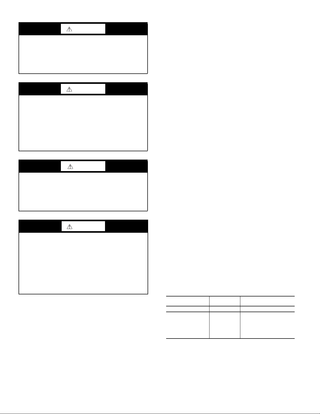
WARNING
UNIT OPERATION AND SAFETY HAZARD
Failure to follow this warning could cause personal injury,
death and/or equipment damage.
Puron (R-410A) refrigerant systems operate at higher pres-
sures than standard R-22 systems. Do not use R-22 service
equipment or components on Puron refrigerant equipment.
WARNING
PERSONAL INJURY AND ENVIRONMENTAL HAZARD
Failure to follow this warning could cause personal injury or
death.
Relieve pressure and recover all refrigerant before system
repair or final unit disposal.
Wear safety glasses and gloves when handling refrigerants.
Keep torches and other ignition sources away from refrigerants and oils.
CAUTION
CUT HAZARD
Failure to follow this caution may result in personal injury.
Sheet metal parts may have sharp edges or burrs. Use care
and wear appropriate protective clothing, safety glasses and
gloves when handling parts and servicing air-conditioning
equipment.
WARNING
CARBON-MONOXIDE POISONING HAZARD
Failure to follow instructions could result in severe personal
injury or death due to carbon-monoxide poisoning, if combustion products infiltrate into the building.
Check that all openings in the outside wall around the vent
(and air intake) pipe(s) are sealed to prevent infiltration of
combustion products into the building.
Check that furnace vent (and air intake) terminal(s) are not
obstructed in any way during all seasons.
INSTALLATION GUIDELINES
Replacement/Retrofit — R-22 to Puron® Refrigerant
Replacement/retrofit installations require change-out of
outdoor unit, metering device, and filter driers. Change-out
of indoor coil (evaporator) and interconnecting tubing is
recommended.
EXISTING EVAPORATOR COIL
If the existing evaporator coil may be re-used, check with
the coil manufacturer to verify the coil construction is suitable for operation with the higher pressures of Puron refrigerant (R-410A). Also determine if the existing TXV valve is
compatible with R-410A, replace if necessary. The minimum
factory test pressure rating must be 250 psig (1725 kPa). Existing coil will need to be purged with Nitrogen to remove as
much mineral oil as possible to eliminate cross contamination of oils.
ACID TEST
If the existing system is being replaced because of a compressor electrical failure, assume acid is in system. If system is being
replaced for any other reason, use an approved acid test kit to determine acid level. If even low levels of acid are detected, install
a 100 percent activated alumina suction-line filter drier in addition to the replacement liquid-line filter drier. Remove the suction line filter drier as soon as possible, with a maximum of 72 hr
of operation. Recommendation: Install a ball valve in the liquid
line at the filter drier location when installing a suction filter in
the suction line.
EXISTING REFRIGERATION PIPING
Reuse of existing refrigerant piping involves three issues:
quality (strength) of existing tubing, cleanliness and tube size.
Inspect all tube segments and joints for signs of damage, corrosion or poor brazing. Flush the interconnecting piping system
with dry Nitrogen to eliminate as much trace of mineral oil as
possible.
Same tube sizes are capable of handling higher flowrates (expressed as tons of cooling capacity) with Puron refrigerant compared to R-22 at constant pressure drops. For example, a
OD liquid line is rated at 33% higher tons with Puron than with
R-22 (at 5°F pressure drop). A 1
1
/8-inch OD suction line is rated
at 53% higher tons with Puron than with R-22 (at 2°F pressure
drop). Refrigeration lines selected for R-22 use are typically
oversized for Puron applications. Carefully check the existing
suction line size against the table for maximum size; replace vertical riser segments if necessary. Check existing liquid line size
against sizing data in Table 1 or 2; replace with smaller lines
when feasible.
Table 1 — Evaporator Coil Connections
EVAPORATOR
COIL HAS
Single Circuit 38AUZ ONLY —
Two Circuits
CONNECT TO
MODEL
38AUZ
or
38AUD
NOTES
Manifold evaporator circuits
into single piping system.
Use two separate piping
systems
1
/2-inch
2

Table 2 — Equivalent Lengths for Common Fittings
(ft)
NOMINAL
TUBE OD
3
/
8
1
/
2
5
/
8
3
/
4
7
/
8
1
1
/
8
3
/
1
8
5
1
/
8
1
2
/
8
NOMINAL
TUBE OD
3
/
8
1
/
2
5
/
8
3
/
4
7
/
8
1
/
1
8
3
1
/
8
5
1
/
8
1
/
2
8
90° Std 90° Lrad 90° Street 90° Std 90° Street
1.3 0.8 2.2 0.6 1.0
1.4 0.9 2.3 0.7 1.1
1.6 1.0 2.5 0.8 1.3
1.8 1.2 2.9 0.9 1.5
2.0 1.4 3.2 0.9 1.6
2.6 1.7 4.1 1.3 2.1
3.3 2.3 5.6 1.7 3.0
4.0 2.6 6.3 2.1 3.4
5.0 3.3 8.2 2.6 4.5
Branch
Flow
2.6 0.8 1.1 1.3
2.7 0.9 1.2 1.4
3.0 1.0 1.4 1.6
3.5 1.2 1.7 1.8
4.0 1.4 1.9 2.0
5.0 1.7 2.3 2.6
7.0 2.3 3.1 3.3
8.0 2.6 3.7 4.0
10.0 3.3 4.7 5.0
ELBOWS
TEES
Straight-Thru
No Reduct Reduce 25% Reduce 50%
NOTE: Equivalent line lengths will vary based on tube diameter.
Calculate equivalent line length for each pipe by adding equivalent length adjustments to linear lengths for each pipe.
Enter the appropriate table to select the recommended line
sizes.
INSTALLATION
1. Remove the existing evaporator coil or fan coil and
install the replacement coil when appropriate.
2. Drain oil from low points and traps in suction line tubing
(and hot gas bypass tubing if appropriate) and evaporator
if they were not replaced. Removing oil from evaporator
coil may require purging of the tubing with dry nitrogen.
3. Unless indoor unit is equipped with a Puron approved
metering device, change the metering device to a thermal
expansion valve (TXV) designed for Puron refrigerant
(R-410A).
4. Remove the existing outdoor unit. Install the new outdoor unit according to these installation instructions.
5. Install a new field-supplied liquid-line filter drier at the
indoor coil just upstream of the TXV or fix orifice metering device.
6. If a suction line filter drier is also to be installed, install
suction line drier downstream of suction line service
valve at condensing unit.
CAUTION
UNIT DAMAGE HAZARD
Failure to follow this caution may result in equipment dam-
age or improper operation. Never install suction-line filter
drier in the liquid line of a Puron system.
7. If required, install a 100% activated alumina suction line
filter drier at the outdoor unit.
8. Evacuate and charge the system according to the instructions in this installation manual.
9. Operate the system for 10 hr. Monitor the pressure drop
across the suction line filter drier. If pressure drop
exceeds 3 psig (21kPa), replace suction-line and liquidline filter driers. Be sure to purge system with dry nitrogen and evacuate when replacing filter driers. Continue
to monitor the pressure drop across suction-line filter
drier. Repeat filter changes if necessary. Never leave suction-line filter drier in system longer than 72 hr (actual
time).
Rated Indoor Airflow (cfm)
Tables 3 and 4 lists the rated indoor airflow used for the
AHRI efficiency rating for the units covered in this document.
Table 3 — 38AUZ with 40RUA
MODEL NUMBERS FULL LOAD AIRFLOW (CFM)
38AUZA/B07 — 40RUA*07 2400
38AUZD/E07 — 40RUA*07 2625
38AUZ*08 — 40RUA*08 3000
38AUZ*12 — 40RUA*12 4000
38AUZ*14 — 40RUA*14 4375
Table 4 — 38AUD with 40RUA
MODEL NUMBERS FULL LOAD AIRFLOW (CFM)
38AUD*12 — 40RUA*12 4000
38AUD*14 — 40RUA*14 4400
Identify Factory Options
Factory options will affect 38AU unit pipe sizing selections.
Coil type impacts liquid lift limits; Hot Gas Bypass impacts
the selection of suction tube size in vertical riser segments.
Check this unit’s Model Number against the Model Number Nomenclature, Fig. 1. Determine the significance of this unit’s values in Position 11 (Coil type) and Position 6 (Hot Gas Bypass,
38AUDC12 only). Copy the unit’s Model Number from the
unit’s dataplate into the open line in the header above Fig. 1 to
facilitate this step. For date of unit manufacture see Serial Number Nomenclature, see Fig. 2.
Matching 38AU Model to Evaporator Coil
The Model 38AUZ is a single-circuit unit design, requiring
one set of refrigeration piping. This model can be connected to
an evaporator coil with one circuit or with two circuits (by manifolding the evaporator connections into a single piping system).
The Model 38AUD is a dual-circuit unit design that requires
two sets of refrigeration piping between the outdoor unit and the
evaporator coil (or coils). This model can only be connected to
an evaporator coil that has two refrigeration circuits (or to two
separate evaporator coils). The Model 38AUD CANNOT be
connected to a single-circuit evaporator coil. The Model 38AUD
CANNOT be field-converted to a single-circuit design.
Before unpacking this new 38AU model, compare the evaporator coil design to the 38AU model.
General
For unit dimensions see Fig. 3. For corner weights see Table 5. For physical data see Table 6.
MODEL/POSITION
#6
38AUZ 71
38AUD 82
TABLE
QUANTITY OF LINE
SETS
3

1 2 3 4 5 6 7 8 9 101112131415161718
DESIGNATESPOSITION
Week of manufacture (fiscal calander)
Manufacturing location5
rebmun ecneuqeS
Year of manufacture (”15” = 2015)
1−2
6−10
3−4
POSITION NUMBER
TYPICAL
12345678910
0515C12345
38AUDC1 2A0A6A0A0A 0
Model Type
38AU = Carrier Condensing Unit
®
Puron
R--- 410A Refrigerant
Typ e of Coi l
Z = Single Circuit, A/C Scroll Compressor
D = Dual Circuit, A/C Scroll Compressor
Refrigerant Options
A = None
B = Low Ambient
C = Hot Gas Bypass (38AUD size 12 only)
D = Single Circuit / 2-Stage (38AUZ size 07 only)
E = Single Circuit / 2-Stage with Low Ambient
(38AUZ size 07 only)
Nominal Tonnage
07 = 6 Tons
08 = 7.5 Tons
12 = 10 Tons
14 = 12.5 Tons
Not Used
A = Not Used
Not Used
0 = Not Used
Packaging
0=Standard
1=LTL
Electrical Options
A = None
C = Non-Fused Disconnect
Service Options
0=None
1 = Un-powered Convenience Outlet
2 = Powered Convenience Outlet
Not Used
A=PlaceHolder
Base Unit Controls
0 = Electro-Mechanical Controls
Design Rev
A = Initial Release
B = 38AUZ(D,E)08 only
Voltage
1 = 575/3/60
5 = 208 / 230/3/6
6 = 460/3/60
Coil Options (RTPF)
A= Cu/Al
B = Precoat (Cu/Al)
C = E-Coat (Cu/Al)
E=Cu/Cu
M= Cu/Al with Louvered Hail Guard
N = Precoat (Cu/Al) with Louvered Hail Guard
P = E-Coat (Cu/Al) with Louvered Hail Guard
R = Cu/Cu with Louvered Hail Guard
Fig. 1 — Model Number Nomenclature
Fig. 2 — Serial Number Nomenclature
4
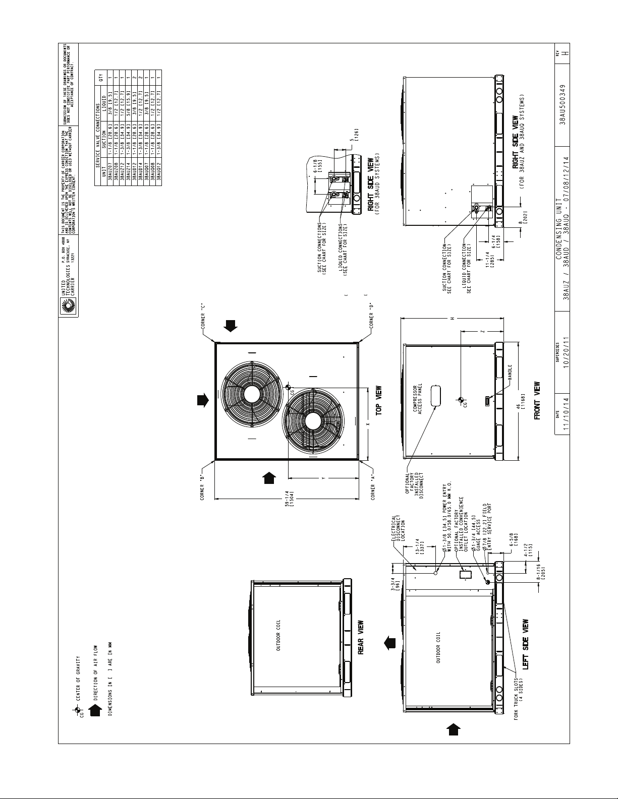
Fig. 3 — 38AUD/Z 07-14 Base Unit Dimensions
5

Table 5 — 38AU Corner Weights
STD. UNIT
UNIT
38AUZ*07 (RTPF) 38917614164964462289141
38AUZ*08
(RTPF)
38AUZ*12 (RTPF) 490 222 177 80 120 54 78 35 114 52
38AUZ*14
(RTPF)
38AUD*12
(RTPF)
38AUD*14
(RTPF)
WT.
lbs. kg. lbs. kg. lbs. kg. lbs. kg. lbs. kg. X Y Z H
39117714264964462289141
598 271 195 88 142 64 110 50 151 68
516 234 185 84 117 53 83 38 131 59
654 297 214 97 155 70 120 54 165 75
CORNER A CORNER B CORNER C CORNER D CENTER OF GRAVITY
18
[457.2]
18
[457.2]
18
[457.2]
20
[508.0]
19
[482.6]
20
[508.0]
24
[609.6]
24
[609.6]
24
[609.6]
25
[635.0]
23
[584.2]
25
[635.0]
21
[533.4]
21
[533.4]
24
[609.6]
24
[609.6]
24
[609.6]
24
[609.6]
Table 6 — 38AU**07-14 Physical Data
SINGLE CIRCUIT MODELS with RTPF – ROUND TUBE/PLATE FIN COIL DESIGN
38AUZ(A,B)07 38AUZ(D,E)07 38AUZ(A,B)08 38AUZ(D,E)08 38AUZ12 38AUZ14
Refrigeration System
# Circuits / # Comp. / Type 1 / 1 / Scroll 1 / 1 / Scroll 1 / 1 / Scroll 1 / 1 / Scroll 1 / 1 / Scroll 1 / 1 / Scroll
Refrigerant Type Puron® R-410A
R-410A shipping charge A/B (lbs, 60 Hz) 9.0 9.0 9.0 9.0 9.0 9.0
System charge w/ fan coil* (60 Hz) 14.0 14.0 17.0 19.0 20.0 43.0
R-410A shipping charge A/B (lbs, 50 Hz) 9.0 NA 9.0 N/A N/A N/A
System charge w/ fan coil* (50 Hz) 14.0 NA 17.0 N/A N/A N/A
Metering device TXV TXV TXV TXV TXV TXV
High-press. Trip / Reset (psig) 630 / 505 630 / 505 630 / 505 630 / 505 630 / 505 630 / 505
Low-press. Trip / Reset (psig) 54 / 117 54 / 117 54 / 117 54 / 117 54 / 117 54 / 117
Compressor
Model ZP61 ZPS60 ZP83 ZPS83 ZP104 ZP137
Oil Charge A/B (oz) 56 56 60 58 110 110
Speed (rpm, 60/50 Hz) 3500 / 2900 3500 / 2900 3500 / 2900 3500 3500 3500
Condenser Coil
Material Al/Cu Al/Cu Al/Cu Al/Cu Al/Cu Al/Cu
Coil type RTPF RTPF RTPF RTPF RTPF RTPF
Rows / FPI 2 / 17 2 / 17 2 / 17 2 / 17 2 / 17 3 / 17
total face area (ft
Condenser fan / motor
Qty / Motor drive type 2 / direct 2 / direct 2 / direct 2 / direct 2 / direct 2 / direct
Motor HP / RPM
Fan diameter (in.) 22 22 22 22 22 22
Nominal Airflow (cfm) 6,000 6,000 6,000 6,000 6,000 6,000
Watts (total) 610 610 610 610 610 610
Piping Connections
Qty / Suction (in. ODS) 1 / 1
Qty / Liquid (in. ODS) 1 / 3/
* Approximate system charge with about 25 ft piping of sizes indi-
cated with matched 40RU.
Jobsite Survey
Complete the following checks before installation.
1. Consult local building codes and the NEC (National
Electrical Code) ANSI/NFPA 70 for special installation
requirements.
2. Determine unit location (from project plans) or select
unit location.
3. Check for possible overhead obstructions which may
interfere with unit lifting or rigging.
2
) 17.5 17.5 17.5 23.0 25.1 31.8
1
/4 / 1100
1
/8 1 / 11/
8
1
/4 / 1100
1 / 3/
1
/4 / 1100
8
8
1 / 11/
1 / 1/
8
2
1
/4 / 1100
1 / 11/
1 / 1/
1
/4 / 1100
8
2
1 / 13/
1 / 1/
8
2
Step 1 — Plan for Unit Location
The 38AU units are designed and approved for outdoor in-
INSTALLATION
stallation only. Do not locate these units indoors. Do not add
ducting to unit fan system.
Select a location for the unit and its support system (pad,
rails or other) that provides for the minimum clearances required for safety. This includes the clearance to combustible
surfaces, unit performance and service access below, around
and above unit as specified in unit drawings. See Fig. 4.
NOTE: Local codes may require different clearances than
specified in Fig. 4. It is the responsibility of installers to be
knowledgeable in local codes and to modify the recommended clearances to satisfy local codes.
NOTE: Consider also the effect of adjacent units on airflow performance and control box safety clearance.
UNIT
HEIGHT
42 3/8
[1076.0]
42 3/8
[1076.0]
50 3/8
[1279.2]
50 3/8
[1279.2]
50 3/8
[1279.2]
50 3/8
[1279.2]
1
/4 / 1100
1 / 13/
1 / 5/
8
8
6

REAR:
Min 18" (457 mm)
required for service
RIGHT:
Min 18" (457 mm)
required for service
LEFT:
Min 18" (457 mm)
required for service
FRONT:
42” (1067 mm)
required for service
NOTE: Observe requirements for 39" (914 mm) operating
clearance on either Left or Rear coil opening.
Fig. 4 — Service Clearance Dimensional Drawing
Do not install the outdoor unit in an area where fresh air
supply to the outdoor coil may be restricted or when recirculation from the condenser fan discharge is possible. Do not
locate the unit in a well or next to high walls.
Evaluate the path and required line length for interconnecting refrigeration piping, including suction riser requirements (outdoor unit above indoor unit), liquid line lift (outdoor unit below indoor unit) and hot gas bypass line. Relocate
sections to minimize the length of interconnecting tubing.
IMPORTANT: DO NOT BURY REFRIGERANT LINES
Although unit is weatherproof, avoid locations that permit
water from higher level runoff and overhangs to fall onto the
unit.
Step 2 — Complete Pre-Installation Checks
CHECK UNIT ELECTRICAL CHARACTERISTICS
Confirm before installation of unit that voltage, amperage
and circuit protection requirements listed on unit data plate
agree with power supply provided.
UN-CRATE UNIT
Remove unit packaging except for the top skid assembly,
which should be left in place until after the unit is rigged into
its final location.
INSPECT SHIPMENT
File a claim with shipping company if the shipment is
damaged or incomplete.
CONSIDER SYSTEM REQUIREMENTS
Consult local building codes and National Electrical Code
(NEC, U.S.A.) for special installation requirements.
Allow sufficient space for airflow clearance, wiring, refrigerant piping, and servicing unit. See Fig. 3 for unit dimensions and weight distribution data.
Locate the unit so that the outdoor coil (condenser) airflow
is unrestricted on all sides and above.
The unit may be mounted on a level pad directly on the base
channels or mounted on raised pads at support points. See Fig. 3
for weight distribution based on recommended support points.
NOTE: If vibration isolators are required for a particular installation, use the data in Fig. 3 to make the proper selection.
Step 3 — Prepare Unit Mounting Support
SLAB MOUNT
Provide a level concrete slab that extends a minimum of
6 in. (150 mm) beyond unit cabinet. Install a gravel apron in
front of condenser coil air inlet to prevent grass and foliage
from obstructing airflow.
Step 4 — Rig and Mount the Unit
CAUTION
UNIT DAMAGE HAZARD
Failure to follow this caution may result in equipment dam-
age or improper operation. Never install suction-line filter
drier in the liquid line of a Puron
®
system.
RIGGING
These units are designed for overhead rigging. Refer to the
rigging label for preferred rigging method. Spreader bars are
not required if top crating is left on the unit. All panels must
be in place when rigging. As further protection for coil faces,
plywood sheets may be placed against the sides of the unit,
behind cables. Run cables to a central suspension point so
that the angle from the horizontal is not less than 45 degrees.
Raise and set the unit down carefully.
If it is necessary to roll the unit into position, mount the
unit on longitudinal rails, using a minimum of 3 rollers. Apply force to the rails, not the unit. If the unit is to be skidded
into position, place it on a large pad and drag it by the pad.
Do not apply any force to the unit.
Raise from above to lift the unit from the rails or pad when
unit is in its final position.
After the unit is in position, remove all shipping materials
and top crating.
Step 5 — Determine Refrigerant Line Sizes
Select the recommended line sizes for 38AUZ and 38AUD
unit from the appropriate tables.
Determine the linear length of interconnecting piping required between the outdoor unit and indoor unit (evaporator).
Consider and identify also the arrangement of the tubing path
(quantity and type of elbows in both lines), liquid line solenoid
size, filter drier and any other refrigeration specialties located
in the liquid line. Refer to the indoor unit installation instructions for additional details on refrigeration specialties devices.
Determine equivalent line length adjustments for path and
components and add to linear line lengths. See Table 2,
Equivalent Lengths for Common Fittings, for usual fitting
types. Also identify adjustments for refrigeration specialties.
Refer to Part 3 of the Carrier System Design Manual for additional data and information on equivalent lengths.
MODEL POSITION TABLE
38AUZ/ALL 71
38AUD/A,B 82
38AUD/C 92
LIQUID LIFT
A liquid lift condition exists when the outdoor unit is located below the indoor (evaporator) unit and liquid flows vertically up in a portion of the liquid line. The vertical column
of liquid reduces the available state point sub-cooling at the
evaporator coil’s thermal expansion valve. This effect reduces the length of liquid lift (feet of elevation) that a liquid line
size can accommodate. Longer linear tube lengths will also
reduce the amount of liquid lift possible.
Check Tables 7 (38AUZ), 8 (38AUD), and 9
(38AUDC12) for maximum liquid lift capabilities for line
sizes. Reselect the liquid line tube size if necessary. If maximum available tube size cannot provide the required lift distance on this installation, relocate the outdoor unit to reduce
the equivalent line length or the lift requirement.
QUANTITY OF LINE
SETS
7

Table 7 — 38AUZ Piping Recommendations (Single-Circuit)
MODEL &
NOMINAL
CAPACITY
LINEAR LINE (FT) 0 - 25 25 - 50 50 - 75 75 - 100 100 - 125 125 - 150 150 - 175 175 - 200
EQUIV. LINE (FT) 0 - 38 38 - 75 75 - 113 113 - 150 150 - 188 188 - 225 225 - 263 263 - 300
Liquid Line Size (in.)
3
/8"3/8"
1
1
/2"
/2"5/8"1/2" 5/8"1/2"5/8"1/2"5/8"1/2"5/8"1/2"5/8"
Liquid PD (F) 2.0 4.0 0.7 1.1 0.3 1.4 0.4 1.8 0.5 2.1 0.6 2.5 0.7 2.8 0.8
Max Lift (ft) 18 7 34 313944574157355431532752
38AUZ*07
Max Lift PD (F) 3.5 4.6 3.5 3.5 3.5 5.0 5.0 5.0 5.0 4.9 5.0 5.0 5.0 5.0 5.0
Suction Line Size (in.)7/8"7/8" 11/8"7/8" 11/8"7/8" 11/8"7/8"11/8"1
1
Suction Ln PD (F) 0.9 1.8 0.5 2.7 0.8 3.6 1.0 4.5 1.3 1.6 1.8 2.1
Charge (lb) 10.8 11.8 13.7 15.2 18.5 16.9 21.3 18.7 24.2 21.4 27.1 23.4 30.0 25.3 32.8
#/TR 1.90 2.07 2.41 2.67 3.25 2.97 3.74 3.28 4.25 3.8 4.75 4.1 5.26 4.4 5.75
Liquid Line Size (in.)
1
/2"1/2"
5
1
/8"
/2"5/8"1/2"5/8"1/2" 5/8"1/2"5/8"1/2" 5/8"1/2"5/8"
Liquid PD (F) 0.6 1.3 0.3 1.9 0.5 2.5 0.7 3.2 0.9 3.8 1.0 4.4 1.2 5.1 1.4
Max Lift (ft) 25 50 50 75 75 100 100 97 97 90 90 82 121 74 119
38AUZ(A,B)08
Max Lift PD (F) 2.7 5.4 4.5 8.1 6.7 10.8 9.0 11.2 8.9 11.2 8.5 11.2 11.2 11.2 11.2
Suction Line Size (in.)7/8"7/8"11/8"7/8"11/8"11/8"1
1
/8"13/8"11/8"13/8"11/8"13/8"11/8"13/8"
Suction Ln PD (F) 1.5 3.1 0.8 4.6 1.2 1.6 2.1 0.7 2.5 0.8 2.9 1.0 3.3 1.1
Charge (lb) 13.6 15.4 16.1 17.2 20.5 19.5 23.3 21.5 27.1 23.4 30.2 25.4 33.2 27.3 36.3
#/TR 1.78 2.02 2.11 2.25 2.68 2.55 3.05 2.81 3.54 3.06 3.95 3.32 4.34 3.57 4.75
Liquid Line Size (in.)
1
/2"1/2"
5
1
/8"
/2"5/8"1/2" 5/8"1/2" 5/8"1/2"5/8"1/2" 5/8"1/2" 5/8"
Liquid PD (F) 0.6 1.3 0.3 1.9 0.5 2.5 0.7 3.2 0.9 3.8 1.0 4.4 1.2 5.1 1.4
Max Lift (ft) 25 50 50 75 75 100 100 97 97 90 90 82 121 74 119
38AUZ(D,E)08
Max Lift PD (F) 2.7 5.4 4.5 8.1 6.7 10.8 9.0 11.2 8.9 11.2 8.5 11.2 11.2 11.2 11.2
Suction Line Size (in.)7/8"7/8"11/8"7/8"11/8"11/8"1
1
/8"13/8"11/8"13/8"11/8"13/8"11/8"13/8"
Suction Ln PD (F) 1.5 3.1 0.8 4.6 1.2 1.6 2.1 0.7 2.5 0.8 2.9 1.0 3.3 1.1
Charge (lb) 15.6 19.0 19.7 20.8 24.1 23.1 26.9 25.1 30.7 26.0 32.8 27.0 34.8 27.9 37.1
#/TR 2.08 2.53 2.63 2.77 3.21 3.08 3.59 3.35 4.09 3.47 4.37 3.60 4.64 3.73 4.95
Liquid Line Size (in.)
1
/2"1/2"
5
1
/8"
/2"5/8"1/2"5/8"1/2"5/8"1/2"5/8"
Liquid PD (F) 0.9 1.9 0.5 2.8 0.8 3.8 1.0 4.7 1.3 5.7 1.6 1.8 2.1
Max Lift (ft) 25 40 50 28 54 34 68 22 65 11 63 59 55
38AUZ*12
Max Lift PD (F) 2.9 5.0 4.5 5.0 5.0 6.5 6.4 6.5 6.4 6.5 6.5 6.4 6.4
Suction Line Size (in.)7/8"7/8"11/8"11/8"13/8"11/8"13/8"11/8"13/8"11/8"13/8"11/8"13/8"11/8"13/8"
Suction Ln PD (F) 2.4 4.8 1.2 1.8 0.6 2.4 0.9 3.1 1.1 3.7 1.3 4.3 1.5 4.9 1.7
Charge (lb) 15.7 17.5 19.7 19.8 23.1 21.6 26.1 23.6 29.2 25.5 32.3 34.1 35.3 36.9 38.4
#/TR 1.67 1.86 2.09 2.10 2.45 2.29 2.77 2.50 3.10 2.71 3.43 3.62 3.75 3.92 4.08
Liquid Line Size (in.)
5
/8"5/8"
3
5
/4"
/8"3/4"5/8"3/4"5/8"3/4"5/8"3/4"5/8"3/4"3/4"7/8"
Liquid PD (F) 0.4 0.8 0.4 1.2 0.6 1.6 0.8 2.0 1.1 2.4 1.1 2.8 1.5 1.7 0.6
Max Lift (ft) 23 16 23 10 18 28 38 21 36 14 35 9 30 25 43
Max Lift PD (F) 1.8 1.84 1.84 1.8 1.8 3.3 3.3 3.3 3.3 3.3 3.3 3.3 3.3 3.3 3.3
38AUZ*14
Suction Line Size (in.) 11/8"11/8"13/8"11/8"13/8"13/8"1
S uc t i on L n PD ( F)
(Cap Red)
1.1 2.2 0.8
3 . 3
(-2.3%)
1.2 1.6 2.0 0.8
3
/8"15/8"13/8"15/8"13/8"15/8"13/8"15/8"
2 . 4
(-0.7%)
Charge (lb) 31.8 34.7 37.6 37.6 41.8 41.1 46.1 44.2 51.6 47.3 56.1 50.3 60.6 63.4 76.9
#/TR 2.62 2.86 3.09 3.09 3.44 3.38 3.79 3.64 4.24 3.89 4.61 4.14 4.98 5.21 6.32
LEGEND
#/TR — Charge to unit capacity ratio, lbs per ton (at 45°F SST, 95°F ODA)
Cap Red — Capacity reduction caused by suction line pressure drop > 2°F
Liquid PD (F) — Liquid line pressure drop, saturated temperature, degrees F
Max Lift — Maximum liquid lift (Indoor unit ABOVE outdoor unit only), at maximum permitted pressure drop.
Max Lift PD (F) — Pressure drop including Maximum liquid lift value
ODA — Outdoor Air
SC — Sub-cooling, degrees F (at liquid line valve)
SST — Saturated Suction Temperature
Suction Ln PD (F) — Suction Line Pressure Drop, saturated temperature, degree F
TC — Total Capacity, MBH (at 45°F Saturated suction, 95°F outdoor air temp)
/8"1
1.0
1
/8"1
5
/8"
2 . 8
(-1.4%)
1.2
3 . 2
(-2.1%)
1
/8"
5
/8"
1.3
8
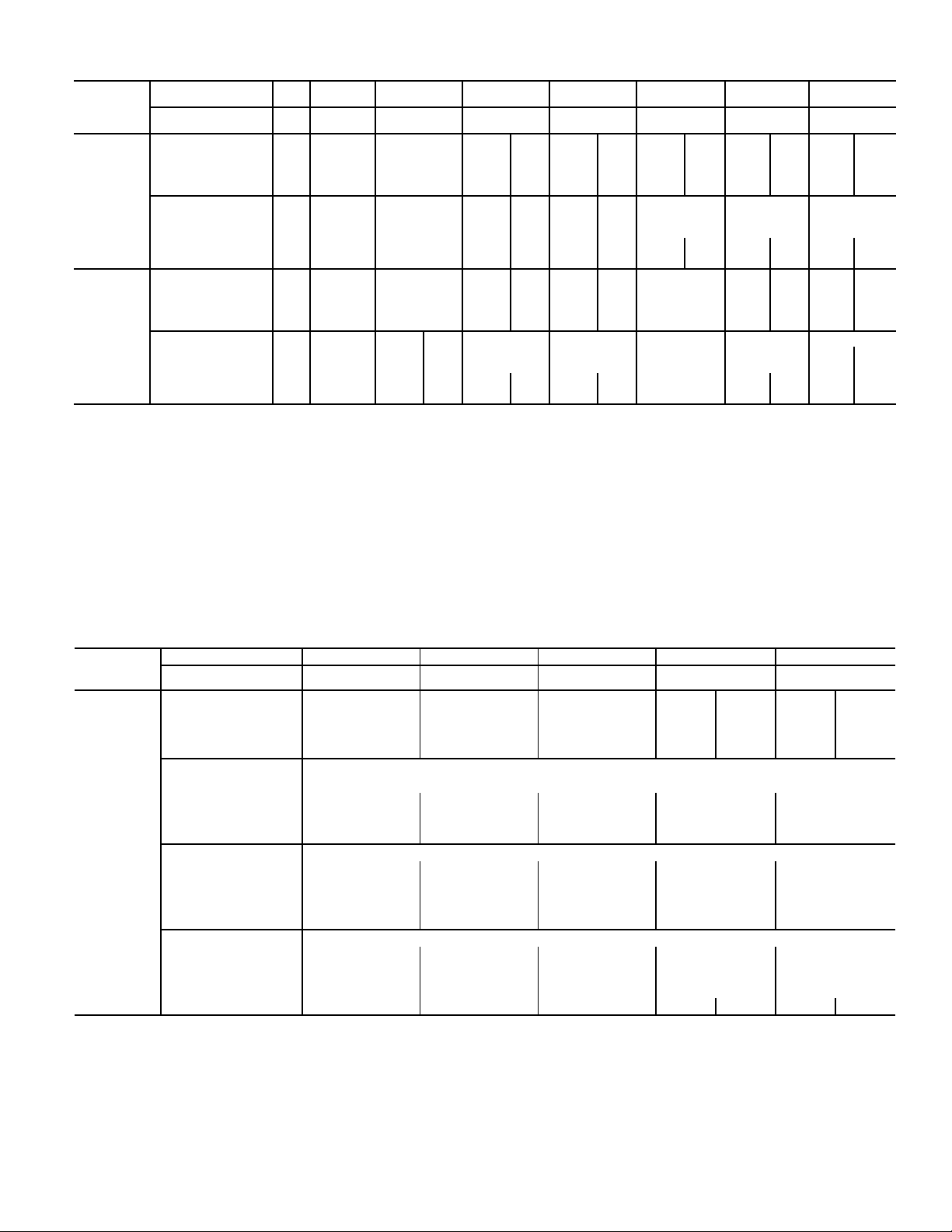
Table 8 — 38AUD Piping Recommendations (Dual-Circuit)
MODEL AND
NOMINAL
CAPACITY
LINEAR LINE
(ft (mm))
EQUIV. LINE
(FT (MM))
Liquid Line Size (in.)
Liquid PD (F) 1.4 2.7 5.5 5.5 0.9 6.9 1.1 8.2 1.4 1.6 0.5 1.8 0.5
Max Lift (ft) 25 50 75 82 100 66 125 49 133 130 144 128 144
Max Lift PD (F) 3.4 6.8 10.2 12.1 9.0 12.1 11.2 12.1 12.1 12.1 12.1 12.1 12.1
38AUD--12
Suction Line Size (in.)
Suction Ln PD
(F) (Cap Red)
Charge (lb) 9.0 10.0 11.0 12.1 15.7 13.1 17.7 14.9 19.6 21.5 28.2 23.5 31.0
#/TR 0.73 0.81 0.89 0.97 1.27 1.05 1.42 1.20 1.58 1.74 2.27 1.89 2.50
Liquid Line Size (in.)
Liquid PD (F) 2.1 4.1 6.2 8.2 1.5 10.3 1.8 2.2 2.6 0.7 2.9 0.8
Max Lift (ft) 128 50 75 69 155 42 125 145 140 163 135 162
Max Lift PD (F) 4.0 8.1 12.1 13.6 9.4 13.6 11.7 13.6 13.6 13.6 13.6 13.6
38AUD--14
Suction Line Size (in.)
Suction Ln PD
(F) (Cap Red)
Charge (lb) 17.0 18.0 19.0 19.5 20.6 23.7 21.8 25.7 27.6 29.5 36.2 31.5 39.0
#/TR 1.36 1.44 1.52 1.56 1.65 1.90 1.74 2.05 2.21 2.36 2.89 2.52 3.12
LEGEND
#/TR — Charge to unit capacity ratio, lbs per ton (at 45°F SST, 95°F ODA)
Cap Red — Capacity reduction caused by suction line pressure drop > 2°F
Liquid PD (F) — Liquid line pressure drop, saturated temperature, degrees F
Max Lift — Maximum liquid lift (Indoor unit ABOVE outdoor unit only), at maximum permitted pressure drop.
Max Lift PD (F) — Pressure drop including Maximum liquid lift value
ODA — Outdoor Air
SC — Sub-cooling, degrees F (at liquid line valve)
SST — Saturated Suction Temperature
Suction Ln PD (F) — Suction Line Pressure Drop, saturated temperature, degree F
TC — Total Capacity, MBH (at 45°F Saturated suction, 95°F outdoor air temp)
0 - 25
25 - 50 50 - 75 75 - 100 100 - 125 125 - 150 150 - 175 175 - 200
(0-8)
0 - 38 38 - 75 75 - 113 113 - 150 150 - 188 188 - 225 225 - 263 263 - 300
3
/8"
3
/4"
1.4 1.2 1.8
3
/8"
7
/8"
1.0 1.9
3
/8"
7
/8"
3
/8"
7
/8"
3
/8"
7
/8"
3
/8"
7
/8"11/8"1
2.9
(-1.5%)
3
/8"
7
/8"11/8"7/8"11/8"1
2.5
(-0.8%)
3
/8"
1
/8"1
0.8 1.1 1.4 1.6 1.9
1
0.8
1
3
1
/2"
/8"
3.1
(-1.9%)
3
/2"
/8"
1
/8"1
3
/2"
/8"
0.9 1.1 1.3 1.5
1
/2"
1
1
/2"
1
/8"1
1
/2"
1
/8"1
5
/2"
/8"1/2"
1
/8"1
1
5
/2"
/8"1/2"
1
/8"1
2 . 2
(-0.3%)
5
/8"
1
/8"
5
/8"
1
/8"
0.7
Table 9 — 38AUDC12 Hot Gas Bypass Piping Recommendations (Dual-Circuit)
MODEL AND
NOMINAL
CAPACITY
38AUDA/B12
NOTES:
1. 38AUDC units require TWO sets of refrigeration piping.
2. For applications with equivalent length greater than 188 ft. (57 m.)
and/or linear length greater than 125 ft. (38 m.), contact your local
Carrier representative.
Linear Line (ft (mm)) 0-25 (0-8) 25-50 (8-15) 50-75 (15-23) 75-100 (23-30) 100-125 (30-38)
Equiv. Line (ft (mm)) 0-38 (0-12) 38-75 (12-23) 75-113 (23-34) 113-150 (34-46) 150-188 (46-57)
Liquid Line Size (in.)
3
/
8
Pressure Drop (°F) 1.8 3.5 5.2 8.7 1.2 8.7 1.5
Max Lift (ft) 25 50 57 65 100 62 125
Pressure Drop (°F) 3.8 7.5 11.3 12.2 9.4 13.7 11.7
Suction Line Size (in.)
Circuit 1: Vapor riser required, not greater than 20 ft (6.1 m) — See Fig. 5
Tube S
Tube A
5
/8 in
5
/8 in
.
.
Pressure Drop (°F) 2.0 2.0 1.9 2.0 2.0
Circuit 1: Vapor riser greater than 20 ft (6.1 m) — See Fig. 6
Tube S
Tube A
5
/8 in
5
/8 in
.
.
Tube B NR
Pressure Drop (°F) 1.6 1.7 1.7 2.1
Circuit 1: No vapor riser required
7
/8 in
.
Circuit 2:
7
/8 in
.
Pressure Drop (°F) 1.1 2.1 0.9 1.2 1.5
Charge (lb) 1/2 13.3 14.3 15.8 16.9 20.0 18.1 22.0
3
/
8
1 1/8 in
5
/8 in
7
/8 in
5
/8 in
1
/2 in
7
/8 in
7
/8 in
3
/
8
.
.
.
.
.
.
.
1 3/8 in
5
/8 in
5
/8 in
5
/8 in
1 1/8 in
1 1/8 in
.
.
.
.
.
.
3
/
8
1 3/8 in
5
/8 in
5
/8 in
5
/8 in
1 1/8 in
1 1/8 in
1
/
2
.
.
.
.
.
.
3
/
8
1 3/8 in
1 1/8 in
1 1/8 in
5
5
5
/8 in
/8 in
/8 in
1
/
2
.
.
.
.
.
.
9
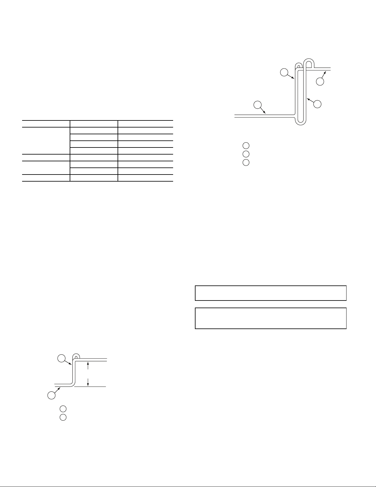
Suction Riser
CONDENSING
UNIT
20-FT (6.1 M) MAX
A
A - Suction Riser Without Trap
LEGEND
S - Suction Line to Condensing Unit
S
FROM
EVAPORATOR
A
A - Suction Riser Without Trap
B - Suction Riser With Trap
S - Suction Line to Condensing Unit
LEGEND
B
S
S
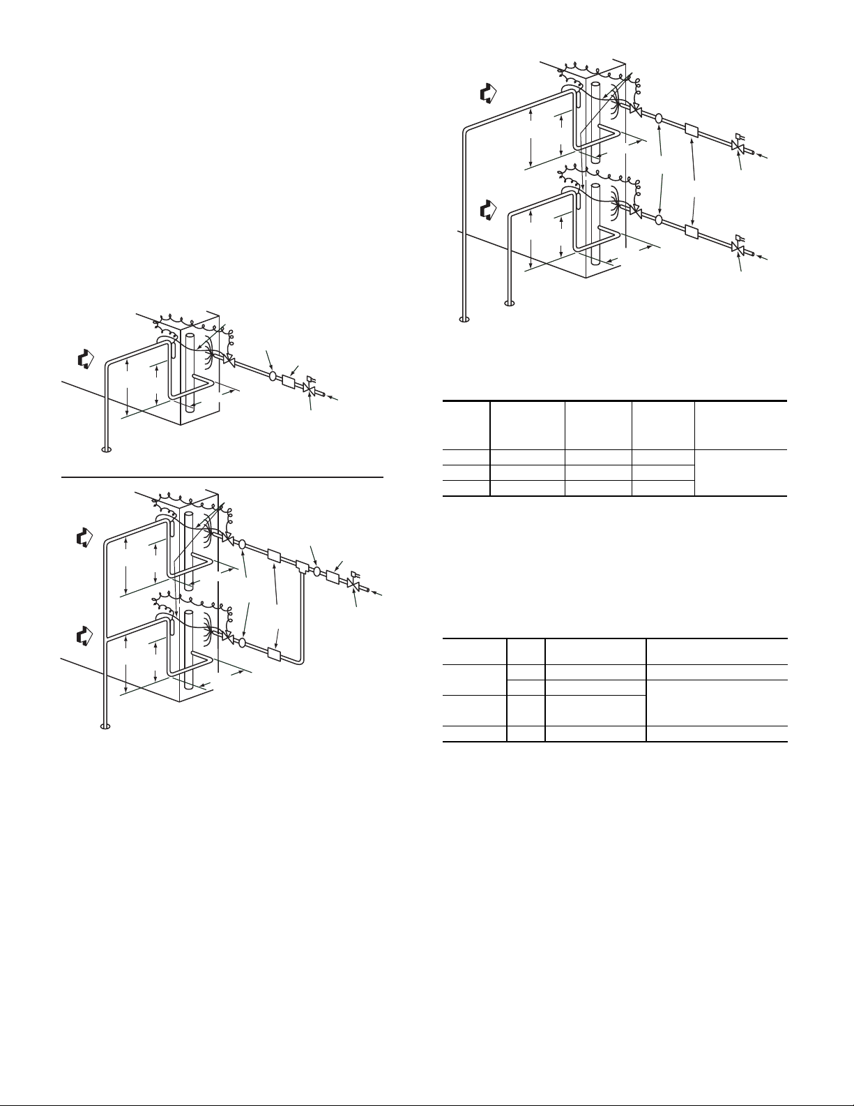
A suction riser condition exists when the outdoor unit is
located above the indoor (evaporator) unit and suction vapor
must flow vertically up to return to the compressor. Oil return
is a concern when the suction tube size is too large to produce
the minimum refrigerant velocity to ensure oil return at minimum load conditions.
38AUZ (ALL) AND 38AUD (A,B) WITHOUT HGBP
Check Table 10 for maximum suction tube size for 38AU
units at minimum load conditions. Consider suction speed riser (reduced tube size for vertical segment only) or double
suction riser arrangement if the planned suction tube size
does not provide necessary minimum flow-rates for this riser.
Table 10 — 38AU Maximum Suction Pipe Size
MODEL UNIT SIZE MAXIMUM TUBE SIZE
38AUZA, B
38AUZD, E 07 1 1/8
38AUDA, B
38AUDC 12 See Table 7
38AUDC12 WITH OPTIONAL HOT GAS BYPASS
Special consideration for suction riser requirements must
be considered when applying this factory-installed hot gas
bypass. It is extremely important to consider the lowest possible refrigerant tons of refrigerant flow when hot gas bypass is
functioning to assure proper oil return up suction risers.
Table 9 provides recommended tube sizes for model
38AUDC12 unit which includes the factory-installed hot gas
bypass system on Circuit 1. The selections in this table are
based on evaluations of system minimum load operating conditions for comfort cooling applications, with compressor saturated suction pressure to 28°F (–2.2°C) minimum.
Table 9 includes liquid line size selections based on use of
RTPF coil option only.
Table 9 includes three different suction line size selections
for Circuit 1 based on the elevation difference conditions between the 38AUD unit and the evaporator coil location.
Outdoor Unit ABOVE Evaporator Coil
This installation will have at least one suction riser segment. If the vertical elevation difference is less than 20-ft (6.1
m) linear feet and requires only one or two segments, consider a speed riser selection for Circuit 1; use the line marked
VAPOR RISER REQUIRED; NOT GREATER THAN 20 FT
(6.1 M). See Fig. 5. Tube S is the horizontal line size; tube A
is the reduced diameter riser size.
(6.1-m) linear feet or requires more than two short lift segments, select the Circuit 1 suction line size from Double
Fig. 5 — Suction Line Piping - Speed Riser
If the vertical elevation difference is greater than 20-ft
07 1 3/8
08 1 5/8
12 1 5/8
14 2 1/8
12 1 3/8
14 1 5/8
Suction Riser lines data under VAPOR RISER GREATER
THAN 20 FT (6.1 M). See Fig. 6. Tube S is the horizontal
line size. Tube A is the reduced diameter riser size without
bottom trap; Tube B is the parallel riser size with bottom oil
trap.
Fig. 6 — Suction Line Piping - Double Riser
Outdoor Unit BELOW Evaporator Coil and No Vertical
Riser Segments
Select Circuit 1 suction line size from NO VAPOR RISER
line.
Circuit 2 Suction Line
Because there is no hot gas bypass system in Circuit 2, no
special riser selections are necessary. Select Circuit 2 suction
line from bottom line for all 38AUDC installations.
Vertical Separation (outdoor unit above indoor unit)
Vertical elevation difference of 200 ft (60 m) is permitted
when the outdoor unit (38AUZ or 38AUD) is located above
the indoor unit.
Step 6 — Complete Refrigerant Piping Connections
IMPORTANT: DO NOT BURY REFRIGERANT LINES.
IMPORTANT: A refrigerant receiver is not provided with
the unit. Do not install a receiver.
PROVIDE SAFETY RELIEF
If local codes dictate an additional safety relief device, purchase locally and install locally. Installation will require the recovery of the factory shipping charge before the factory tubing
can be cut and the supplemental relief device is installed.
Model 38AUD has two separate refrigeration systems. If
required, each circuit will require a field-supplied/installed
supplemental relief device.
CHECK 38AU MODEL WITH EVAPORATOR COIL CONNECTIONS
Confirm before installation of unit that the evaporator coil
connections are consistent with this 38AU model. See Table 1
on page 2.
INSULATE SUCTION LINES
Apply closed-cell tubular insulation to all suction lines between evaporator coil connection and 38AU unit’s suction
service valve.
10

38AUD PIPING CONNECTIONS
Circuit 1
Connections
Circuit 2
Connections
CKT
2
CKT
1
The 38AUD unit’s two circuits are designated Circuit 1
and Circuit 2. Circuit 1 is controlled by the thermostat’s Y1
(or TC1) contact and will be the first circuit on and last circuit
off. Circuit 2 is controlled by the thermostat’s Y2 (or TC2)
contact and this circuit is always the “lag” circuit.
See Fig. 7 for location of Circuit 1 and Circuit 2 service
valves and field piping connections. Circuit 1 is on the righthand side of the service valve compartment; Circuit 2 is on
the left.
When a single piece evaporator coil with two separate circuits is connected to a 38AUD, the lower coil circuit should
be connected to the 38AUD unit’s Circuit 1 so that the evaporator’s lower coil segment is first-on/last-off (to avoid reevaporation of condensate on dry lower coil segments).
LIQUID LINE
CONNECTION
SUCTION-VAPOR
CONNECTION
CONDENSATE DRAIN
CONNECTION
FIRST ON/LAST OFF = 2
VERTICAL INSTALLATION
CONDENSATE DRAIN CONNECTION
FIRST ON/LAST OFF = 1
HORIZONTAL INSTALLATION
Fig. 7 — 38AUD Service Valve Locations
Plan the Circuit 1 and Circuit 2 tubing segments carefully,
mark each segment and check constantly as piping systems
are assembled to avoid piping errors.
38AUD unit cannot be field-piped as a single-circuit/tandem
system.
FINAL TUBING CHECK. 38AUD
Before completing the field piping connections to the
38AUD unit service valves, confirm that the suction line to the
indoor coil’s first-on/last-off circuit (and its companion liquid
line) are correctly identified as Circuit 1 use for the 38AUD
unit. If a suction riser is required, it must be in Circuit 1.
Connecting 40RU to 38AUD
The 40RU fan coil in sizes 12, 14 and 16 is a face-split coil
design that also has its circuits designated as 1 and 2. See
Fig. 8. Note that the lower coil segment changes as the arrangement of the 40RU changes. In a vertical arrangement,
the 40RU unit’s lower coil segment is segment 2; this segment should be connected to the 38AUD unit’s Circuit 1. In a
horizontal arrangement, the 40RU unit’s lower segment is
now segment 1; this segment should be connected to the
38AUD unit’s Circuit 1.
Note that refrigerant suction piping should be insulated.
ARRANGEMENT
40RU
Vertical
Horizontal
COOLING
STAGE
Y1 2 Circuit 1
Y2 1 Circuit 2
Y1 1 Circuit 1
Y2 2 Circuit 2
40RU COIL
SEGMENT
CONNECT TO
38AUD
Fig. 8 — Typical Evaporator Coil Connections
(40RU)
INSTALL FILTER DRIER(S) AND MOISTURE INDICATOR(S)
Every unit MUST have a filter drier in the liquid line.
38AUD models require two filter driers (one in each liquid
line). Locate the filter drier(s) at the indoor unit, close to the
evaporator coil’s thermal expansion valve (TXV) inlets.
The 38AU units include one (38AUZ) or two (38AUD)
Puron-duty filter drier(s), shipped in cartons attached to the
unit basepan (see Table 11). Remove the filter drier(s) and
prepare to install in the liquid line(s) at the evaporator coil.
Do not remove connection fitting plugs until ready to connect
and braze the filter drier into the liquid line position.
Table 11 — Puron-duty Filter Drier(s)
MODEL
SIZE
38AUZ*07 1
38AUZ*07 1
38AUZ*07 1
38AUZ*07 1
38AUD*12 2
38AUD*14 2
QTY
LIQUID LINE
OD (in.)
3
/
8
1
/
2
1
/
2
5
/
8
3
/
8
1
/
2
DESICCANT
VOLUME
8 cu in. KH43LG091
16 cu in. KH43LG085
16 cu in. KH43LG085
16 cu in. KH43LG086
8 cu in. KH43LG091
16 cu in. KH43LG085
PART
NUMBER
REF.
Installation of liquid line moisture indicating sightglass in
each circuit is recommended. Locate the sightglass(es) between
the outlet of the filter drier and the TXV inlet.
Refer to Table 12 for recommendations on refrigeration
specialties.
In some applications, depending on space and convenience requirements, it may be desirable to install 2 filter driers and sight glasses in a single circuit application. One filter
drier and sight glass may be installed at A locations (see Fig.
9) or 2 filter driers and sight glasses may be installed at B locations (see Fig. 9 and 10).
11
Select the filter drier for maximum unit capacity and mini-
INDOOR
COIL CKT 2
AIRFLOW
INDOOR
COIL CKT 1
AIRFLOW
15 DIAMS
MIN
10
DIAMS
8 DIAMS
MIN
TXV
SENSING
BULB
EQUALIZER LINE
SIGHT GLASS
A LOCATION
SIGHT
GLASSES
B LOCATION
TXV
CKT 2
FILTER DRIER
A LOCATION
FILTER
DRIERS
B LOCATION
FLOW
TXV
SENSING
BULB
TXV
CKT 1
8 DIAMS
MIN
15 DIAMS
MIN
10
DIAMS
SINGLE CIRCUIT COIL PIPING CONFIGURATION
FOR SINGLE COMPRESSOR CONDENSING UNITS
DUAL CIRCUIT COIL PIPING CONFIGURATION
FOR SINGLE COMPRESSOR CONDENSING UNITS
15 DIAMS
MIN
10
DIAMS
8 DIAMS
MIN
INDOOR
COIL CKT
AIRFLOW
TXV
SENSING
BULB
EQUALIZER LINE
SIGHT GLASS
A LOCATION
TXV
FILTER DRIER
A LOCATION
LIQUID LINE
SOLENOID
VALVE
FLOW
LIQUID LINE
SOLENOID
VALVE
AIRFLOW
SUCTION
CIRCUIT 2
SUCTION
CIRCUIT 1
AIRFLOW
15 DIAMS
MIN
10
DIAMS
8 DIAMS
MIN
TXV
SENSING
BULB
EQUALIZER LINE
SIGHT
GLASSES
TXV
CKT 2
FILTER
DRIERS
LIQUID LINE
SOLENOID VALVE
CIRCUIT 2
FLOW
LIQUID LINE
SOLENOID VALVE
CIRCUIT 1
FLOW
TXV
SENSING
BULB
TXV
CKT 1
8 DIAMS
MIN
15 DIAMS
MIN
10
DIAMS
DUAL CIRCUIT COIL PIPING CONFIGURATION
FOR TWO CIRCUIT CONDENSING UNITS
mum pressure drop. Complete the refrigerant piping from the
indoor unit to the outdoor unit before opening the liquid and
suction lines at the outdoor unit.
INSTALL LIQUID LINE SOLENOID VALVE
It is recommended that a solenoid valve be placed in the
main liquid line (see Fig. 9 and 10) between the condensing
unit and the evaporator coil. Locate the solenoid valve at the
outlet end of the liquid line, near the evaporator coil connections, with flow direction arrow pointed at the evaporator
coil. Refer to Table 12. (A liquid line solenoid valve is required when the liquid line length exceeds 75 ft [23 m].) This
valve prevents refrigerant migration (which causes oil dilution) to the compressor during the off cycle, at low outdoor
ambient temperatures. Wire the solenoid in parallel with the
compressor contactor coil (see Fig. 9 and 10). This means of
electrical control is referred to as solenoid drop control.
Fig. 9 — Location of Sight Glass(es) and Filter
Driers Typical 38AUZ Systems
Fig. 10 — Location of Sight Glasses and Filter
Driers Typical 38AUD Systems
Table 12 — Refrigerant Specialties Part Numbers
LINE
SIZE
3
/
1
/
5
/
LIQUID LINE
SOLENOID
VALVE
(LLSV)
EF680033 EF680037 KM680008
8
EF680035 EF680037 KM680004
2
EF680028 EF680032 KM680005
8
LLSV COIL
SIGHT
GLASS
Provided with
LIQUID
Solenoid Drop Control Wiring
Control the power to the liquid line solenoid through a Solenoid Valve Relay (SVR) in all units. Use part number
HN61PC005 (field-supplied, installed). 38AUZ unit requires
one SVR; 38AUD unit requires two relays.
A unit with two liquid line solenoid valves also requires a
separate control power transformer for the liquid solenoid
valve loads. Select TRAN3 transformer part number according to unit power supply.
QTY
MODEL
38AUZ
RELAY SVR QTY
LSV
- PART NUMBER
1 1 — HN61PC005 N/R
2 2 — HN61PC005 208/230V: HT01BD202
38AUDA,B 2 2 — HN61PC005
TRAN3 PRIMARY V:
PART NUMBER
460V: HT01BD702
575V: HT01BD902
38AUDC 2 1 — HN61PC005 N/R #
LEGEND
LSV —Liquid Solenoid Valve
SVR — Solenoid Valve Relay
N/R —Not Required
N/R # —Not Required / Factory Installed
* Install as SVR-2 (SVR-1 is factory-installed).
12
FILTER
DRIER
unit, see
Table 11
Mount the SVR (and transformer TRAN3 when used) in
FACTORY
HIGH-FLOW
ACCESS PORT
SERVICE VALVE
WITH STEM CAP
FIELD SERVICE
ACCESS PORT
(SCHRADER CORE)
SWEAT
CONNECTION
unit control box. Connect per wiring schematic label on unit.
NOTE: TRAN3 is provided with the HGBP factory installed op-
tion for 38AUDC12 units.
Evaporator Capacity Control Liquid Line Solenoid Valve
Many older unit designs included automatic capacity controls that sensed changes in suction pressure and could increase or decrease compressor capacity automatically as the
evaporator load changed. Control systems were used on these
units that had the thermostat’s second stage contacts control a
capacity control liquid line solenoid valve to open or shutoff
a portion of the evaporator surface without any direct connection to the compressor circuit.
This form of system capacity staging control is not possible with 38AU models. If this installation is a retrofit for a
unit that included automatic pressure-operated unloading,
check the existing thermostat and liquid solenoid valve.
When found, convert the evaporator second stage solenoid
control into a drop-solenoid control. Use the two SVR relays
and transformer as required on 38AUD models (above); wire
the SVRs and transformer per two solenoid valve systems.
SELECTING AN ACCUMULATOR
Because all 38AU models use scroll compressors, an accumulator is not required. If an accumulator is to be added,
check the accumulator manufacturer’s literature carefully for
indication of its suitability for use with R-410A; look for
minimum working pressure of 200 psig (1380 kPa). Select
the accumulator first on the basis of its cataloged minimum
capacity (tons) to ensure oil return from the accumulator, then
on tube size or holding capacity.
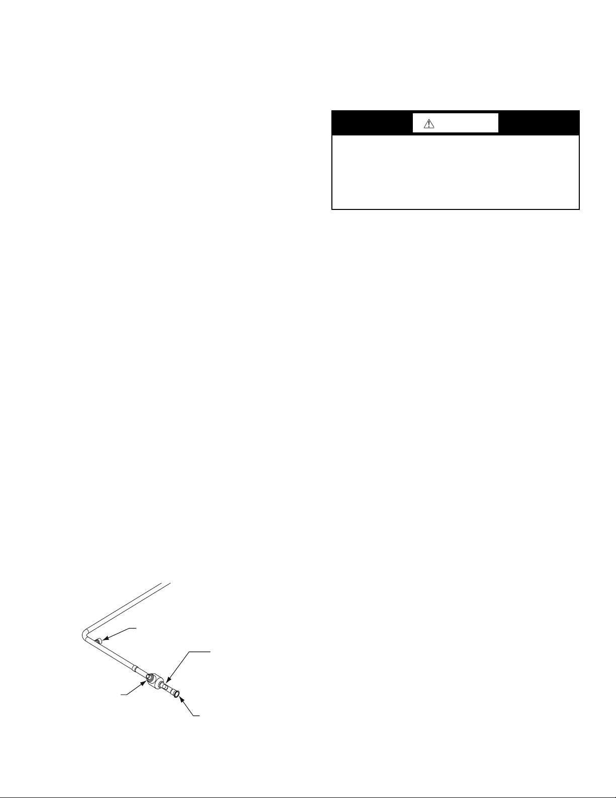
MAKE PIPING CONNECTIONS
Piping connections at the 38AU unit are ball valves with
stub tube extensions. Do not open the unit service valves until
all interconnecting tube brazing has been completed. The stub
tube connections include
Schrader valve cores (see Fig. 11). Before making any brazed
connections to the unit service valves, remove both Schrader
valve caps and cores and save for re-installation. Connect a
source for nitrogen to one of these service fittings during tube
brazing to prevent the formation of copper oxides inside the
tubes at brazed joints.
When connecting the field tubing to the 38AU service
valves, wrap the valves in wet rags to prevent overheating.
Pressure-test all joints from outdoor unit connections over
to the evaporator coil, using nitrogen as pressure and with
soap-and-bubbles.
When pressure-testing is completed, remove the nitrogen
source at the outdoor unit service valves and re-install the
two Schrader valve cores. Torque the cores to 2-3 in.-lbs
(23-34 N-cm).
Fig. 11 — Typical Piping Connection Assembly
1
/4-in. SAE service fittings with
EVACUATION/DEHYDRATION
Evacuate and dehydrate the connected refrigeration system(s) (excluding the 38AU unit) to 500 microns using a twostage vacuum pump attached to the service ports outside the
38AU service valves, following description in GTAC II,
Module 4, System Dehydration.
WARNING
UNIT OPERATION AND SAFETY HAZARD
Failure to follow this warning could cause personal injury,
death and/or equipment damage.
Puron (R-410A) refrigerant systems operate at higher pressures than standard R-22 systems. Do not use R-22 service
equipment or components on Puron refrigerant equipment.
This unit is designed for use with Puron (R-410A) refrigerant. Do not use any other refrigerant in this system.
Puron (R-410A) refrigerant is provided in pink (rose) colored cylinders. These cylinders are available with and without dip tubes; cylinders with dip tubes will have a label indicating this feature. For a cylinder with a dip tube, place the
cylinder in the upright position (access valve at the top) when
removing liquid refrigerant for charging. For a cylinder without a dip tube, invert the cylinder (access valve on the bottom) when removing liquid refrigerant.
Because Puron (R-410A) refrigerant is a blend, it is strongly
recommended that refrigerant always be removed from the cylinder as a liquid. Admit liquid refrigerant into the system in the
discharge line. If adding refrigerant into the suction line, use a
commercial metering/expansion device at the gauge manifold;
remove liquid from the cylinder, pass it through the metering
device at the gauge set and then pass it into the suction line as a
vapor. Do not remove Puron (R-410A) refrigerant from the cylinder as a vapor.
PRELIMINARY CHARGE
Before starting the unit, charge R-410A liquid refrigerant
into the high side of each 38AU circuit through the liquid service valve(s). The amount of refrigerant added must be at
least 80% of the operating charge listed in Table 6 for LINEAR line length LESS the factory charge quantity (if factory
shipping charge has not been removed). See example below.
Allow high and low side pressures to equalize. If pressures
do not equalize readily, charge R-410A vapor (using special
service manifold with expansion device) into the suction line
service port for the low side of system to assure charge in the
evaporator. Refer to GTAC II, Module 5, Charging, Recover,
Recycling, and Reclamation for liquid charging procedures.
Example:
38AUZ*12
60-ft (18.3 m) linear line length
Equivalent line length 90-ft (27.4 m)
Liquid Lift: 20-ft (6.1 m)
Select line sizes from Table 7 (38AUZ):
Liquid
Suction 1
Charge 23.1 lbs (at 75-ft linear length)
80% of Operating Charge:
0.80 x 23.1 = 18.5 lbs
Factory Shipping Charge: 9 lbs
Field-Charge quantity: 18.5 - 9.0 = 9.5 lbs
For linear line lengths longer than 125 ft (38 m), contact
your local Carrier representative for system charge value.
13
1
/2 in.
1
/8 in.
Step 7 — Install Accessories
COPPER
WIRE ONLY
ELECTRIC
DISCONNECT
SWITCH
ALUMINUM
WIRE
Accessories requiring modifications to unit wiring should
be completed now. These accessories may include Winter
Start controls and Low Ambient controls. Refer to the instructions shipped with the accessory.
Step 8 — Complete Electrical Connections
WARNING
ELECTRICAL SHOCK HAZARD
Failure to follow this warning could cause personal injury or
death.
Do not use gas piping as an electrical ground. Unit cabinet
must have an uninterrupted, unbroken electrical ground to
minimize the possibility of personal injury if an electrical
fault should occur. This ground may consist of electrical wire
connected to unit ground lug in control compartment, or conduit approved for electrical ground when installed in accordance with NEC (National Electrical Code); ANSI/NFPA
70, latest edition (in Canada, Canadian Electrical Code CSA
[Canadian Standards Association] C22.1), and local electrical codes.
NOTE: Check all factory and field electrical connections for
tightness. Field-supplied wiring shall conform with the limitations of 63°F (33°C) rise.
FIELD POWER SUPPLY
If equipped with optional Powered Convenience Outlet: The
power source leads to the convenience outlet’s transformer primary are not factory connected. Installer must connect these
leads according to required operation of the convenience outlet.
If an always-energized convenience outlet operation is desired,
connect the source leads to the line side of the unit-mounted disconnect. (Check with local codes to ensure this method is acceptable in your area.) If a de-energize via unit disconnect switch operation of the convenience outlet is desired, connect the source
leads to the load side of the unit disconnect. On a unit without a
unit-mounted disconnect, connect the source leads to compressor contactor C and indoor fan contactor IFC pressure lugs with
unit field power leads.
Field power wires are connected to the unit at line-side
pressure lugs on compressor contactor C and TB1 (see wiring
diagram label for control box component arrangement) or at
factory-installed option non-fused disconnect switch. Max
wire size is #4 AWG (copper only).
NOTE: TEST LEADS — Unit may be equipped with short
leads (pigtails) on the field line connection points on contactor C
or optional disconnect switch. These leads are for factory runtest purposes only; remove and discard before connecting field
power wires to unit connection points. Make field power connections directly to line connection pressure lugs only.
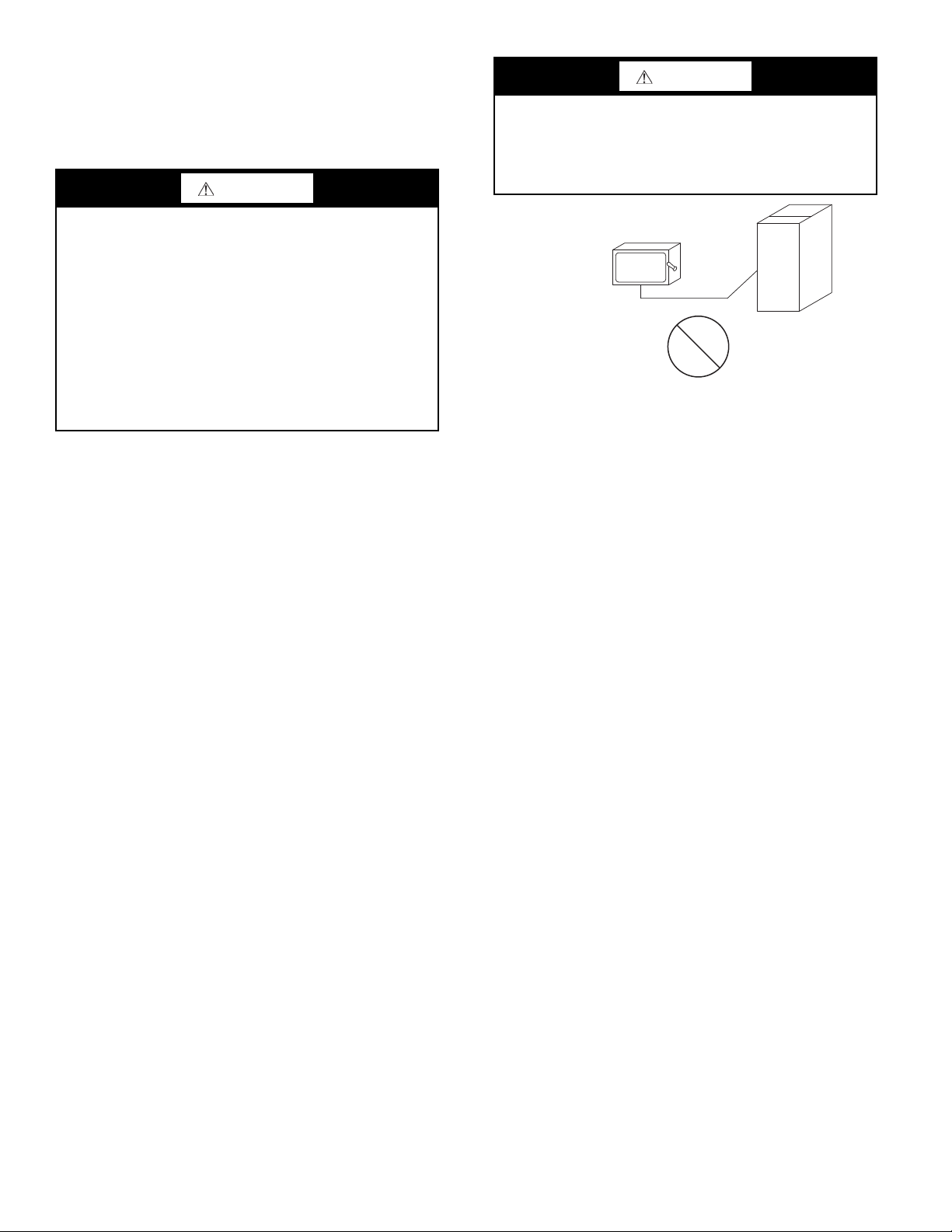
WARNING
FIRE HAZARD
Failure to follow this warning could result in personal injury,
death, and/or equipment damage.
Do not connect aluminum wire between disconnect switch
and condensing unit. Use only copper wire. (See Fig. 12.)
Fig. 12 — Disconnect Switch and Unit
UNITS WITH FACTORY-INSTALLED NON-FUSED DISCONNECT
The factory-installed option disconnect switch is located
in a weatherproof enclosure located under the main control
box. The manual switch handle is accessible through an opening in the access panel.
UNITS WITHOUT FACTORY-INSTALLED NON-FUSED DISCONNECT
When installing units, provide a disconnect switch per
NEC (National Electrical Code) of adequate size. Disconnect
sizing data is provided on the unit informative plate. Locate
on unit cabinet or within sight of the unit per national or local
codes. Do not cover unit informative plate if mounting the
disconnect on the unit cabinet.
ALL UNITS
All field wiring must comply with NEC and all local
codes. Size wire based on MCA (Minimum Circuit Amps) on
the unit informative plate. See Fig. 13 for power wiring connections to the unit contactor and terminal block and equipment ground.
Provide a ground-fault and short-circuit over-current protection device (fuse or breaker) per NEC Article 440 (or local
codes). Refer to unit informative data plate for MOCP (Maximum Over-current Protection) device size.
All units except 208/230-v units are factory wired for the
voltage shown on the nameplate. If the 208/230-v unit is to be
connected to a 208-v power supply, the control transformer must
be rewired by moving the black wire with the
spade connector from the 230-v connection and moving it to the
1
208-v
/4-in. male terminal on the primary side of the transform-
er. Refer to unit label diagram for line-side information.
Affix the crankcase heater warning sticker to the unit disconnect switch.
1
/4-in. female
14
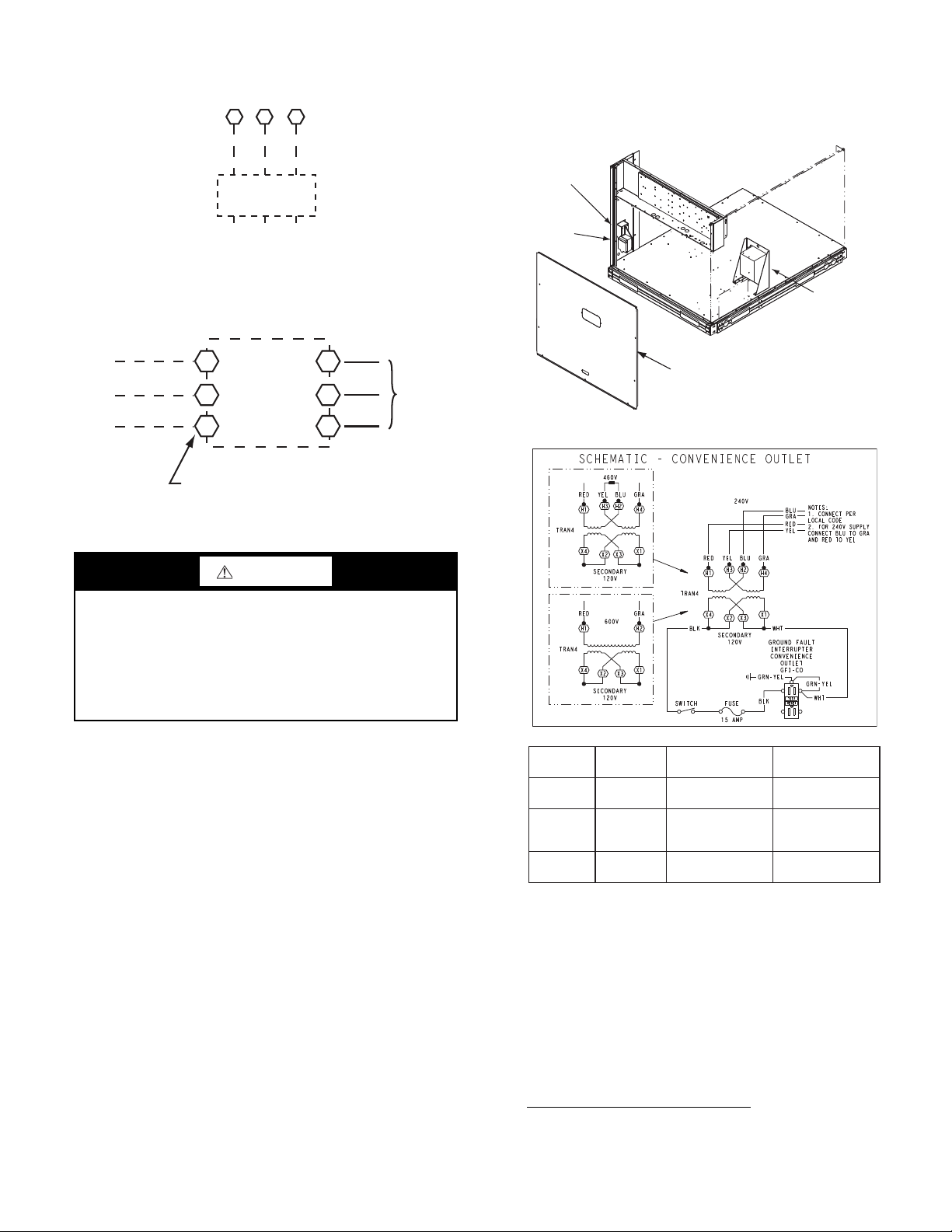
Fig. 13 — Power Wiring Connections
11 13
L1
L2 L3
C TB1
208/230-3-60
460-3-60
575-3-60
Units Without Disconnect Option
Units With Disconnect Option
2
4
6
1
3
5
L1
L2
L3
Optional
Disconnect
Switch
Disconnect factory test leads; discard.
Factory
Wiring
Disconnect
per
NEC
Control Box
Access Panel
Pwd-CO
Transformer
Convenience
Outlet
GFCI
Pwd-CO
Fuse
Switch
CONVENIENCE OUTLETS
mounted non-fused disconnect or HACR breaker switch; this
will provide service power to the unit when the unit disconnect
switch or HACR switch is open. Other connection methods will
result in the convenience outlet circuit being de-energized when
the unit disconnect or HACR switch is open. See Fig. 15.
Fig. 14 — Convenience Outlet Location
WARNING
ELECTRICAL OPERATION HAZARD
Failure to follow this warning could result in personal injury
or death.
Units with convenience outlet circuits may use multiple dis-
connects. Check convenience outlet for power status before
opening unit for service. Locate its disconnect switch, if
appropriate, and open it. Tag-out this switch, if necessary.
Two types of convenience outlets are offered on 38AU
models: Non-powered and unit-powered. Both types provide
a 125-volt GFCI (ground-fault circuit-interrupter) duplex receptacle rated at 15-A behind a hinged waterproof access
cover, located on the end panel of the unit. See Fig. 14.
Non-Powered Type
This type requires the field installation of a general-purpose 125-volt 15-A circuit powered from a source elsewhere
in the building. Observe national and local codes when selecting wire size, fuse or breaker requirements and disconnect
switch size and location. Route 125-v power supply conductors into the bottom of the utility box containing the duplex
receptacle. Maximum continuous current for this type of convenience outlet (non-unit powered) must not exceed 8 Amps.
Unit-Powered Type
A unit-mounted transformer is factory-installed to step
down the main power supply voltage to the unit to 115-v at
the duplex receptacle. This option also includes a manual
switch with fuse, located in a utility box and mounted on a
bracket behind the convenience outlet; access is through the
unit’s control box access panel. See Fig. 14.
The primary leads to the convenience outlet transformer are
not factory-connected. Selection of primary power source is a
customer-option. If local codes permit, the transformer primary
leads can be connected at the line-side terminals on the unit-
UNIT
VOLTAGE
208,
230
460 480
575 600
CONNECT
AS
240
PRIMARY
CONNECTIONS
L1: RED + YEL
L2: BLU + GRA
L1: RED
Splice BLU + YEL
L2: GRA
L1: RED
L2: GRA
TRANSFORMER
TERMINALS
H1 + H3
H2 + H4
H2 + H3
Fig. 15 — Powered Convenience Outlet Wiring
The unit-powered convenience outlet has a 1000 VA rated
transformer. Maximum continuous current must not exceed
8Amps.
Test the GFCI receptacle by pressing the TEST button on
the face of the receptacle to trip and open the receptacle. Check
for proper grounding wires and power line phasing if the GFCI
receptacle does not trip as required. Press the RESET button to
clear the tripped condition.
Fuse on power type: The factory fuse is a Bussman
“Fusetron” T-15, non-renewable screw-in (Edison base) type
plug fuse.
1. Bussmann and Fusetron are trademarks of Cooper Technologics
Company.
15
H1
H4
H1
H2
1
WARNING
TOP
TOP
TOP
WET LOCATIONS
WET LO
CATIONS
ELECTRICAL OPERATION HAZARD
Failure to follow this warning could result in personal injury
or death.
Using unit-mounted convenience outlets: Units with unit-
mounded convenience outlet circuits will often require that
two disconnects be opened to de-energize all power to the
unit. Treat all units as electrically energized until the convenience outlet power is also checked and de-energization is
confirmed. Observe National Electrical Code Article 210,
Branch Circuits, for use of convenience outlets.
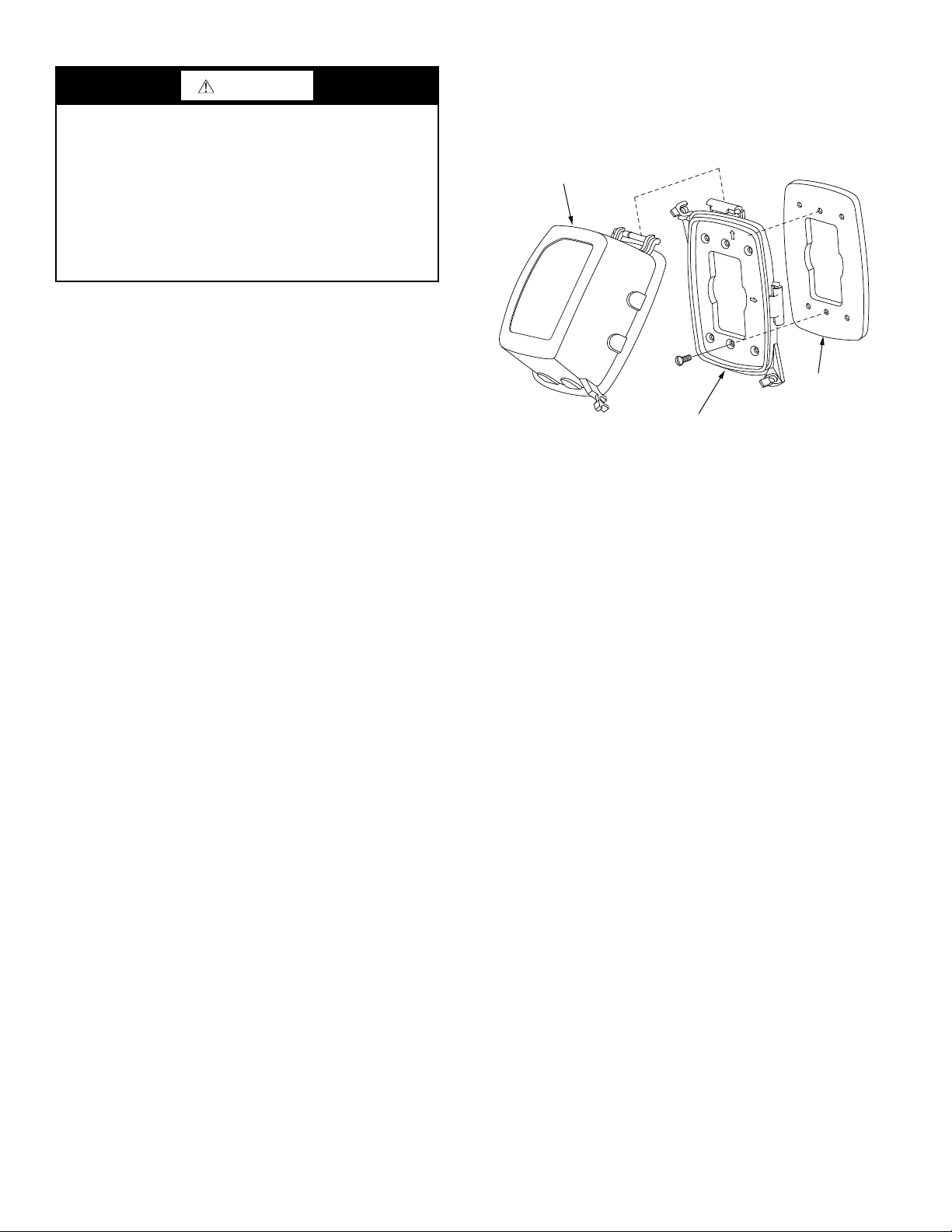
Installing Weatherproof Cover
A weatherproof while in use cover for the factory installed
convenience outlets is now required by UL standards. This
cover cannot be factory mounted due its depth; it must be installed at unit installation. For shipment, the convenience outlet is covered with a blank cover plate.
The weatherproof cover kit is shipped in the unit’s control
box. The kit includes the hinged cover, a backing plate and
gasket.
DISCONNECT ALL POWER TO UNIT AND CONVENIENCE OUTLET.
Remove the blank cover plate at the convenience outlet;
discard the blank cover.
Loosen the two screws at the GFCI duplex outlet, until approximately
Press the gasket over the screw heads. Slip the backing plate
over the screw heads at the keyhole slots and align with the
gasket; tighten the two screws until snug (do not overtighten).
Mount the weatherproof cover to the backing plate as
shown in Fig. 16. Remove two slot fillers in the bottom of the
cover to permit service tool cords to exit the cover. Check for
full closing and latching.
ALL UNITS
Voltage to compressor terminals during operation must be
within voltage range indicated on unit nameplate. See Tables
13-16. On 3-phase units, voltages between phases must be balanced within 2% and the current within 10%. Use the formula
1
/2-in. (13 mm) under screw heads are exposed.
shown in the legend for Tables 13-16, Note 4 (see page 18) to
determine the percent of voltage imbalance. Operation on improper line voltage or excessive phase imbalance constitutes
abuse and may cause damage to electrical components. Such
operation would invalidate any applicable Carrier warranty.
GFCI RECEPTACLE
COVER - WHILE-IN-USE
WEATHERPROOF
BASEPLATE FOR
GFCI RECEPTACLE
NOT INCLUDED
GASKET
Fig. 16 — Weatherproof Cover Installation
FIELD CONTROL WIRING
38AU unit control voltage is 24 v. See Fig. 17-19 for typical field control connections and the unit’s label diagram for
field-supplied wiring details. Route control wires to the
38AU unit through the opening in unit’s end panel to the connections terminal board in the unit’s control box.
Remainder of the system controls connection will vary according to the specific construction details of the indoor section
(air handler or packaged fan coil). Fig. 20 (38AUZ) and 21
(38AUD) depict typical connections to a Carrier 40RU fan coil
unit. Plan for field connections carefully and install control
wiring correctly per the project plan. Additional components
and supplemental transformer accessory may be required.
The 38AU unit requires an external temperature control device. This device can be a thermostat (field-supplied) or a PremierLink controller (available as a field-installed accessory, for
use on a Carrier Comfort
®
Network or as a stand alone control).
16
 Loading...