

Page 1
GB
D
F
I
USE & MAINTENANCE INSTRUCTIONS
BEDIENUNGSANLEITUNG
INSTRUCTIONS D'USAGE ET ENTRETIEN
MANUALE USO E MANUTENZIONE
C
C
U
U
-
-
O
O
Page 2
2 Carrier
SERVICE SHEET - SERVICEBLATT - FICHE DE SERVICE - FOGLIO SERVIZIO
DATE - DATUM OPERATION - MASSNAHME SERVICE FIRM - SERVICEFIRMA
SIGNATURE - UNTERSCHRIFT
DATE - DATA OPERATION - OPERAZIONE ETS DE SERVICE - DITTA ASSISTENZA SIGNATURE - FIRMA
Page 3

1. Description of the unit ....................................................................page 4
1.1 How the unit works ............................................................................page 4
1.2 Safety devices and safety measures ................................................page 4
1.3 Synopsis of signs ..............................................................................page 5
1.4 Residual risks ....................................................................................page 6
2. Technical features of the unit ........................................................page 7
3. Intended uses ..................................................................................page 7
3.1 Dangers deriving from using the unit for purposes
other than those it is designed for ....................................................page 7
4. Moving the unit................................................................................page 8
5. Installation........................................................................................page 8
5.1 Signs..................................................................................................page 8
5.2 Dimensions of unit and packing ........................................................page 8
5.3 Commissioning ..................................................................................page 9
5.4 Area surrounding the unit to be kept clear ........................................page 9
6. Assembly and preparation for commissioning ............................page 9
6.1 Cleaning the unit................................................................................page 11
6.2 Connecting the unit to external power sources ................................page 11
6.2.1 Power mains connection ..................................................................page 11
6.2.2 Water mains connection ....................................................................page 12
6.3 Checks, adjustments and settings ....................................................page 12
6.4 Setting of the controll and power devices..........................................page 12
7. Start-up ............................................................................................page 13
7.1 Electrical controls ..............................................................................page 13
7.1.1 Control panel ....................................................................................page 13
8. How to use the unit ........................................................................page 13
8.1 Description of the unit’s work cycle ..................................................page 13
8.2 Diagram of the unit’s electrical system ..............................................page 13
9. Maintenance and repairs ................................................................page 14
9.1 General maintenance operations ......................................................page 14
9.2 Special maintenance operations ......................................................page 14
9.3 Operations to be carried out by qualified personnel
or by the manufacturer ......................................................................page 14
9.4 Troubleshooting guide ......................................................................page 14
9.5 Parts subject to wear and spares ......................................................page 15
10. Disposal of packaging ....................................................................page 15
11. Disassembling the unit ..................................................................page 15
GB
D
F
I
Carrier 3
List of contents
Page 4
Thank you for choosing a uniblock product.
Please read this booklet carefully - it has been specially designed to provide
advice and information on how to install, use and maintain the unit correctly, so
as to use it to the best of its capacities.
The term CAUTION is used to indicate situations that may cause damage to
the unit. These appear in italics.
The term WARNING is used to indicate situations that might endanger the
safety of operators. These appear in italics and, in some case, also in bold.
All measures indicated in this catalogue are stated in millimetres
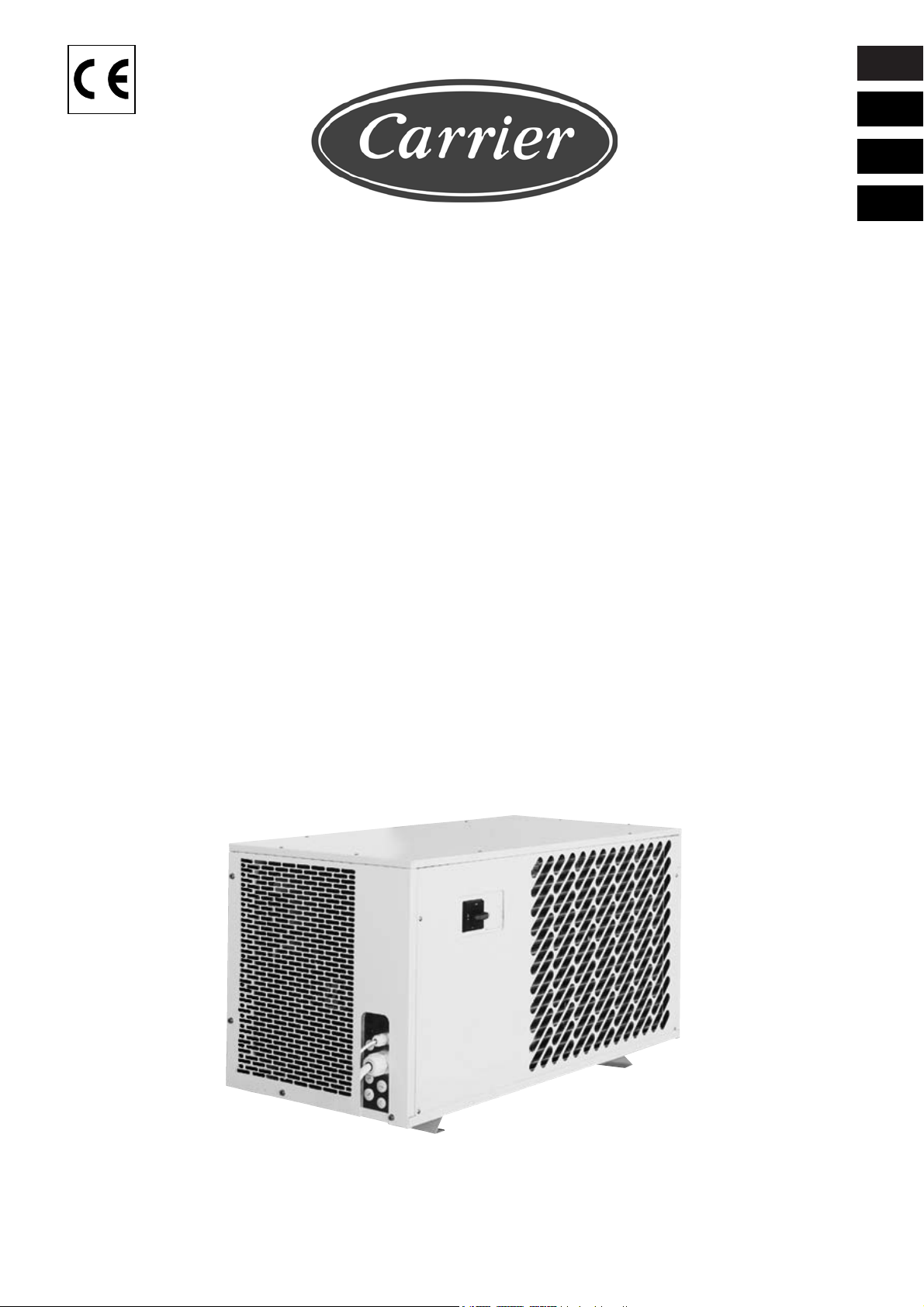
T he CU-O range consists in:
1. a condenser unit, with air or water condensation installed external to the cell
2. an electrical control panel, located on the condenser unit
1.1 How the unit works The units CU-O are condensing parts operating by means of a sealed or semisealed a/c mains powered refrigerating compressor (three-phase), using HFC
refrigerating liquids.
1.2 Safety devices and safety measures
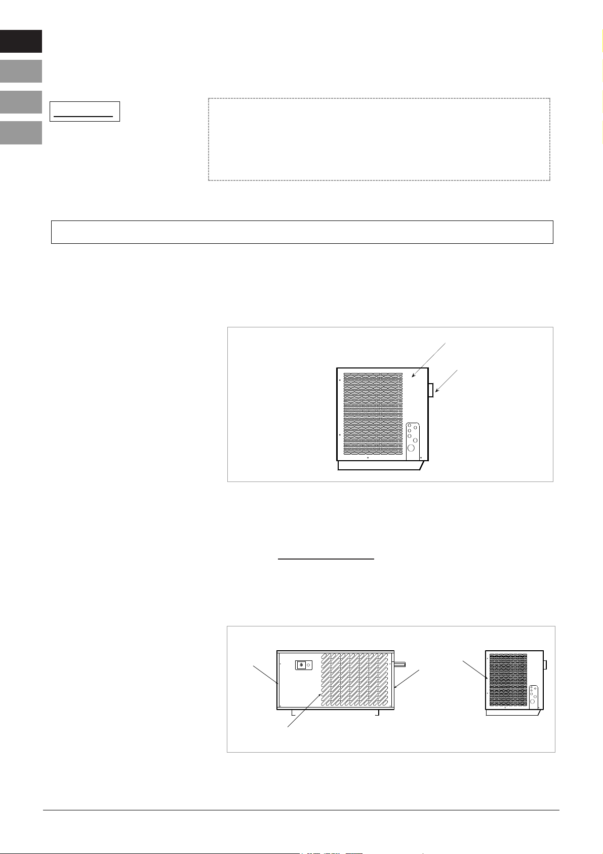
The following mechanical safety devices are supplied by the manufacturer (fig. 2):
1. fixed side guards of the evaporator and condenser units: these are fixed to the
metal casing with locking screws.
GB
D
F
I
4 Carrier
LEGENDA
fig.1
1
2
fig.2
1
1
1
1
1. DESCRIPTION OF UNIT
Page 5
The following electrical safety devices are supplied by the manufacturer:
1. Fan thermal protection (incorporated into the motors) with manual resetting:
protects electric fans against excessive current absorption.
2. High pressure switch with manual resetting: protects against excessively high
pressure.
3. Thermistors or thermostats with manual resetting: protects the motor against
overheating.
4. Minimum/maximum tension electronic relay (monitor) with automatic resetting
(optional).
WARNING
Safety devices have been designed by the manufacturer to ensure the safety of
operators while carrying out their work
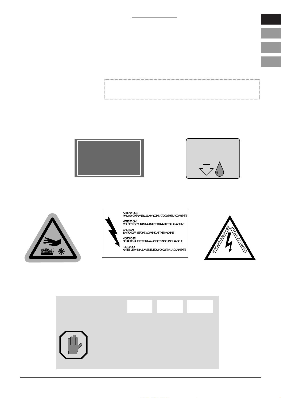
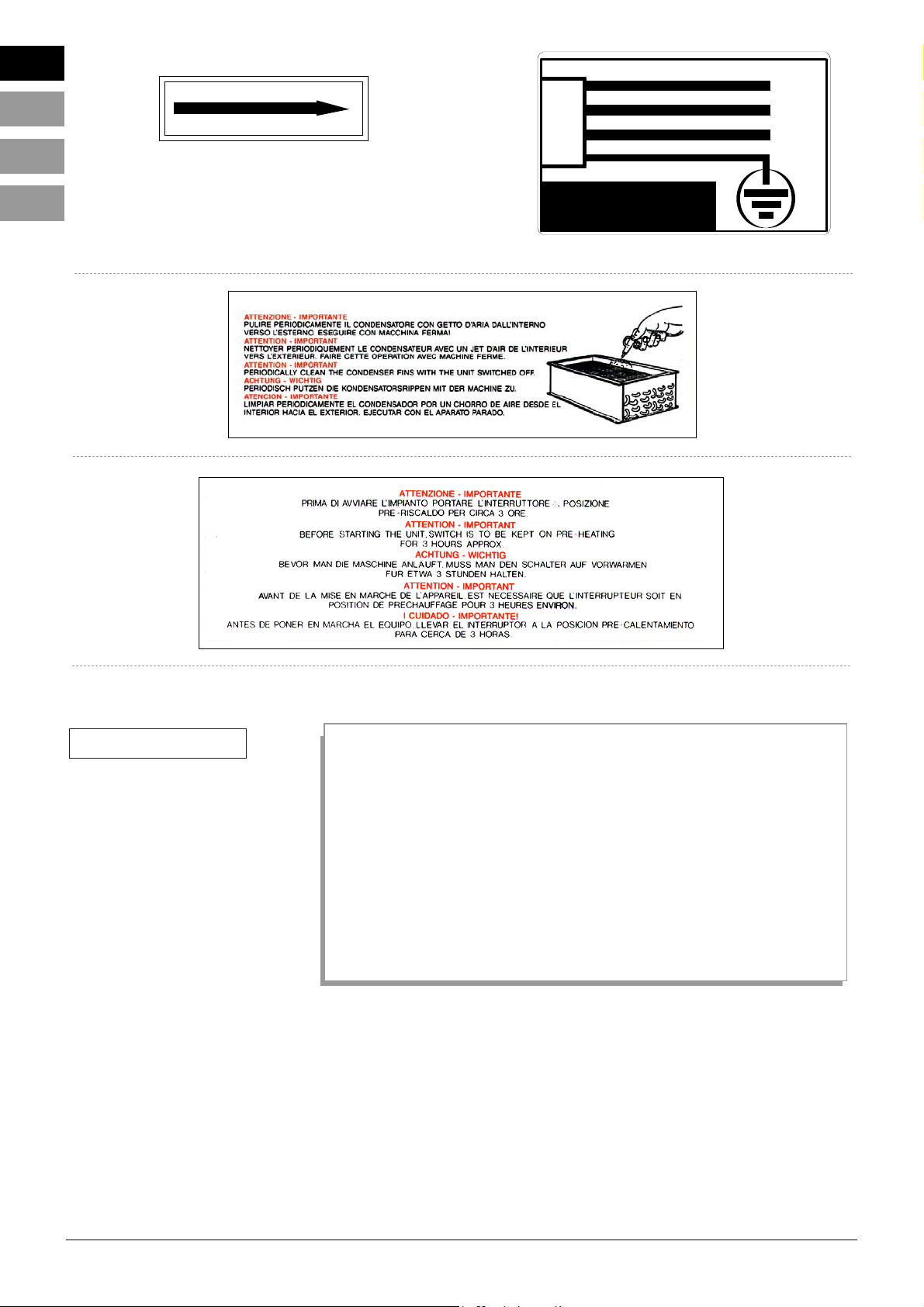
1.3 Synopsis of labels The following caution and warning signs have been placed on the unit by the
manufacturer:
INDICATION:
TYPE OF REFRIGERATING LIQUID
WARNING:
CAUTION!
hot and/or cold parts
CAUTION:
GB
D
F
I
Carrier 5
ATTENZIONE! PERICOLO
Volt
Phases
Hz
COLLEGAMENTO UNIBLOCK
UNIT ELECTRICAL CONNECTION
CONNEXION DE L'UNITE'
EL EK TR ISCH. AN SCHLU S S
CONEXION DE L'UNIDAD
COLLEGARE QUESTO CAVO AD UN INTERRUTTORE MAGNETOTERMICO. MAI
DIRETTAMENTE ALLA LINEA PRINCIPALE.
CONNECTION SHOULD ALWAYS BE MADE FROM A FUSED ISOLATOR. NEVER CONNECT
THE CABLE TO THE MAINS SUPPLY LINE DIRECTLY
LA CONNEXION DOIT ETRE EFFECTUEE AU MOYEN D'UN INTERRUPTEUR MAGNETOTHERMIQUE. JAMAIS CONNECTER LE CABLE A LA LIGNE PRINCIPALE DIRECTEMENT
DER ANSCHLUSS DES KABELS SOLL DURCH EINEN THERMOMAGNETSCHALTER
FOLGEN. KEIN DIREKTER ANSCHLUSS DER HAUPTSPEISELEITUNG
CONNECTAR EL CABLE A UN INTERRUPTOR MAGNETOTERMICO. Y NUNCA
A LA LINEA DIRECTAMENTE
R 404 A
3ETA237
SCARICO CONDENSA
CONDENSATE DRAIN LINE
ECOULEMENT DE CONDENSATION
KONDENSATABLAßROHR
DESAGÜE CONDENSACíON
Page 6
Direction of rotation
1.4 RESIDUAL RISKS
Below we list all the situations - from the delivery of the unit to its demolition
- in which the user will need to exercise caution in order to avoid damage to
persons.
CHAPTER 4 - Positioning the unit
Maximum caution should be used in ensuring that no one passes through
the area while the suspended load is being handled, in order to avoid any
chance of damage to persons.
CHAPTER 9 - Maintenance
Condenser and evaporator groups’ fins: any maintenance operations must
be carried out using personal protection devices (e.g. gloves) in order to
avoid any chance of damage to hands.
GB
D
F
I
6 Carrier
GIALLO/VERDE JAUNE/VERT
GELB/GRUEN YELLOW/GREEN
L2
L1
L3
V.400/3~/50 Hz.
Page 7
The specific technical features of each CU model are indicated on the data plate
attached to the unit (fig. 3).
The CU-O ranges are air condensing units manufactured to operate automatically.
Using the machine for any purposes other than those envisaged represents an anomaly and may seriously endanger people’s safety.
3.1 Dangers deriving from using the The unit is not designed to operate in premises where explosives are stored.
unit for purposes other than Therefore, it is categorically forbidden to use it in locations where any risk of
those it is designed for explosion exists.
Should the user wish to use the unit for any purposes or in any fields other than
those intended (see ch. 8, section 8.2 of this manual), or wish to modify the unit
in any way, he should consult the manufacturer/distributor about any contraindications or dangers that may derive from the incorrect use of the unit.
GB
D
F
I
Carrier 7
2. TECHNICAL FEATURES OF THE UNIT
fig.3
Mod.
Mod.
Matricola
Serial Number
Ten si on e
Vol tage
Assorb. Marcia
Run Absorption
Refrigerante
Refrigerant
Massa
Mass
AKw
Kg
Via Martin L. King, nr. 30
46020 PEGOGNAGA
(Mantova) - Italy
ZANOTTI
SS..pp..AA..
Modello
Model
Potenza compressore
Compressor power
A
Assorb. Max
Max Absor.
Kw
Schemi
Diagr.
1) Anno di costruzione
2) Codice unità "CARRIER"
3) Numero matricola
4) Tensione
5) Assorbimento Marcia (Macchina)
6) Assorbimento massimo
7) Assorbimento di spunto (Macchina all' avviamento)
8) Potenza nominale compressore
9) Refrigerante : Tipo ; Quantità
10) Massa macchina
11) Numero schema elettrico (Progetto)
Carrier Refrigeration AB
A
Ass. Spunto
Start. Abs.
Kg
3. INTENDED USES
1) Year of manufacture
2) Carrier unit code
3) Serial number
4) Voltage
5) Operating current
6) Maximum current
7) Starting current
8) Compressor’s nominal power
9) Refrigerating liquid Type; Quantity
10) Mass of the unit
11) Electric diagram (Project) number
Page 8
The unit can be moved with lifting and transport devices. (Fig.4)
WARNING
Take the utmost care in ensuring no one passes through the platform truck’s
manoeuvring area, so as to avoid any risk to personnel while the load is
being handled.
The unit is shipped packed in a wooden case or in a wooden crate: the
movement has to be done securing the packaging with a sling in an appropriate way.
Take special care in ensuring that the packing crate containing the unit is not lif-
ted too quickly to avoid oscillations which may damage or break the unit.
5.1 Signs The Manufacturer has envisaged the posting of the following caution and warning signs:
Caution: Low /high temperature
Switch off before handling the unit
Caution: danger
5.2 Dimensions of unit and packing CU range units come in different sizes, as indicated in the following diagrams (fig. 5-6).
CU 401 - 451 - 501 - 631 /O
GB
D
F
I
8 Carrier
5. INSTALLATION
fig.4
4.
POSITIONING THE UNIT
fig.5
* delivery pipe
** suction pipe
Cod. H G
GCU401 10 22
HCU401 10 28
GCU451 12 28
HCU451 12 35
GCU501 12 28
HCU501 12 35
GCU631 12 28
HCU631 12 42
Mod. A B C D E F
CU401 52 542 1075 105 532 28
CU451 52 602 1575 105 642 28
CU501 52 602 1575 105 642 28
CU631 83 802 1725 105 742 28
C
D
ø G**
ø H*
E
F
A
B
Page 9
PACKING
5.3 Commissioning In order to achieve optimum performance, the unit must be:
a) Place the cell in a well ventilated room, away from heat sources .
b) Check that the unit has adequate aspirating and extracting power.
5.4 Area surrounding the unit In order to allow it to work properly and to facilitate its maintenance in safety conditions, the unit should be installed providing the minimum spatial requirements
for opening the unit, indicated in figs 5.
Ensure that no damage has occurred to the unit or the equipment it contains
during transportation, particularly to the components fixed to the electric control
panel door and to the refrigerating system pipes. To install the unit, proceed as
indicated in the diagrams, taking special care to level the unit (fig.7).
Connect the condensing unit to its evaporator following the diagrams of the fig.7
and using pipes with the correct diameter as indicated in the enclosed tables.
GB
D
F
I
Carrier 9
fig.6
Mod. A B C Kg
CU401-O 670 1350 810 56
CU451/501-O
780 1850 865 89
CU631-O 880 2000 1100 114
A
B
C
6. ASSEMBLY AND PREPARATION PRIOR TO COMMISSIONING
fig. 7
PIANO PAVIMENTO
fig. 7.a
-Section of suction
line in an installation
having the compres
sor sited underneath
heevaporator
Insulate the whole
suction line
FLOOR PLANE
Page 10

GB
D
F
I
10 Carrier
PIANO PAVIMENTO
fig.7.b
Insulate the whole suc-
tion line
-First section of the
suction line in an
installation having
the compressor
sited above the
evaporator (difference of level less
than 3 mt)
fig.7
PIANO PAVIMENTO
fig.7.c
Insulate the whole
suction line
-First section of the
suction line in an
installation having
the compressor
sited above the
evaporator (difference of level
more than 3 mt).
FLOOR PLANE
FLOOR PLANE
Page 11

D
F
I
Carrier 11
6.1 Cleaning the unit
Carefully clean the unit with detergents or degreasing substances, removing dust, dirt
and any foreign matter that may have deposited on it during transportation.
CAUTION! Do not use solvents
6.2 Connecting the unit to external 6.2.1 Power mains connection
energy sources Before making the electrical connection, ensure that the voltage and frequency of
the mains supply are as indicated on the unit’s serial plate and that the power
supply is within +/- 10% of nominal value
Having conducted a preliminary inspection of the elements of the panel, make the
electrical connection. Connection to the mains supply must be made through a
magnetothermal or fused switch.
Safety devices (magnetothermal and/or fused switches ) should be installed on the
power supply line taking into account the current absorption indicated on the plate.
For instance:
Current absorption indicated on the plate:
Operating current 12KW - 28,5 A
Maximum current 40 A
Starting absorption 134A
In this case, a 40A magnetothermal switch with a “C” curve (CEI 23.3 IV -EN 60-
898) should be installed. Alternatively, an appropriately sized fused switch should
be used for the maximum 40A current, which should also be capable of withstan-
ding a 134A starting current without being tripped. The system must be fitted with
an adequate equipotential safety circuit (earth connection).
It is also advisable to install a differential switch at source.
Follow the diagram below to make the electrical connection correctly for CU-O :
Id
Esempio con
CON FUSIBILI
INTERRUTTORE
N
L3
L2
L1
400V 3~ N 50Hz
Id
42
N
5
3
1
N6
MAGNETOTERMICO
Esempio con
400V 3~ N 50Hz
INT.
DIFFERENZIALE
INTERRUTTORE GENERALE
INT.
DIFFERENZIALE
INTERRUTTORE GENERALE
N
L3
L2
L1
UNITÀ CONDENSANTE
GB
Id
Esempio con
CON FUSIBILI
INTERRUTTORE
N
L3
L2
L1
400V 3~ N 50Hz
Id
42
N
5
3
1
N6
MAGNETOTERMICO
Esempio con
400V 3~ N 50Hz
INT.
DIFFERENZIALE
INTERRUTTORE GENERALE
INT.
DIFFERENZIALE
INTERRUTTORE GENERALE
N
L3
L2
L1
UNITÀ CONDENSANTE
CONDENSER UNIT
Ex: MAGNETOTHERMAL
SWITCH
Ex.: FUSED SWITCH
MAINS SWITCH
DIFFERENTIAL SWITCH
MAINS SWITCH
DIFFERENTIAL SWITCH
fig.8
Page 12

GB
D
F
I
12 Carrier
When a cell contains more than one unit, each should be fitted with its own
magnetothermal switch.
Now connect the unit paying attention to the colour of the wires that make up the
power supply cable:
a) 230V/3~/50-60 Hz 4 wires Blue = phase
Yellow/green = earth
Brown = phase
Black = phase
b) 400V/3N~/50-60 Hz 5 wires Blue = neutral
Yellow/Green = earth
Brown = phase
Black = phase
Black = phase
N.B.: All units are supplied with terminals 3-4 to which it is possible to connect
any device not alive; for example an ambient thermostat.
CAUTION
Magnetothermal safety switches should be used to protect the main power sup-
ply line from power surges.
Only qualified personnel is authorised to replace the safety thermal relays fitted
on motors.
Only qualified personnel must be authorised to make electrical connections.
6.2.2 Connection to the water mains (water condenser)
The water condenser must be connected to the water mains following the indications
on the plates next to the tubes, which are marked IN (ENTRATA) and OUT (USCITA). The diameter of the pipes used to make the connection must not be smaller
than the unit’s outlet tubes. Pressure in the water circuit must be at least 1 bar.
6.3 Checks, adjustments and settings Before switching the machine on, ensure that:
- locking screws are fixed tight
- electrical connections have been made correctly
When the unit is opened, check that:
- no tools have been left inside
- assembly has been correctly performed
- there are no gas leaks
- panels have been correctly fixed.
6.4 Setting of the control and During the testing on make the setting of these devices. Below we list the rated
power devices values of the pressure switches settings; these values must be considered
approximates as size order.
Low pressure switch 0,2 bar
high pressure switch 28 bar working with R404A
Page 13

D
F
I
Carrier 13
I ON
GB
To start the machine up proceed as follows:
A) Adjust the ambient thermostat, which is on the evaporator, to the desired tempera-
ture inside the refrigerating cell. Units with remote control panels are equipped with
an electronic room thermostat which is located on the remote control panel itself.
The thermostat can be connected following the scheme; or it can work on the sole-
noid valve which pipes the refrigerant to the evaporator.
B) Position the switch preheating/stop/running, arranged by the customer, on
preheating (the indication for the connection is in the electric scheme).
C) Move the mains switch to position (ON). Leave the unit in the pre-start position
for at least 4 hours. If the temperature is particularly cold, keep the unit in the
pre-start position for at least 12 hours.
D) At the end of the pre-start phase, move the pre-start/stop/start switch to opera-
ting position.
E) If the compressor fails to start, check:
- connection to the power supply
- a blockage in the minimum pressure switch due to the lack of refrigerating gas. In this case the leak must be identified and repaired before
refilling the compressor and proceeding again with the operations
illustrated above.
- Faulty auxiliary fuse = identify and eliminate the cause.
7.1 Electrical controls 7.1.1 Control panel
The CU-O units use only one model of control panel. (fig.9)
8.1 Description of the unit Uniblock CU refrigerating units operate through a sealed or semi-sealed refrige-
working cycle rating compressor, powered by mains a/c supply (three phase) and use HFC
refrigerating liquids.
8.2 Diagram of the unit’s Units in the CU-O range feature a special electrical system, a diagram
electrical system of which is attached to this manual.
7. PLACING INTO SERVICE OF THE UNIT
I ON
fig.9
Mains
switch
8. HOW TO OPERATE THE UNIT
Page 14

GB
D
F
I
14 Carrier
Adequate maintenance is an important factor to ensure the long life and optimum
performance of the unit and the safety conditions required by the Manufacturer.
9.1 General maintenance It is essential to clean the condenser which is located in the lower part of the
compressor unit (externally to the cell) in an easily accessible position.
The condenser is used to cool the refrigerating gas and it will work more effecti-
vely if it is kept free of dust.
The unit can be cleaned by simply using a dry brush and reaching deep between
the condenser’s fins or, better still, by using an air jet and blowing from the inside
out. This operation must be carried out while the unit is switched off.
If there are traces of oil on the condenser, check where they come from and,
having repaired the leak, clean using a detergent such as alcohol or petrol.
WARNING: To avoid cutting your hands, use protective gloves.
9.2 Special maintenance operations Periodically check the wear of electrical contacts and remote control switches
and replace if necessary.
9.3 Operations to be carried out Below is a list of maintenance operations that require specific technical compe-
by qualified personnel or by tencies and must therefore be carried out by qualified personnel or by the
the Manufacturer Manufacturer.
The User must on no account:
- replace electrical components
- tamper with the electric system
- make repairs on mechanical parts
- tamper with the refrigerating system
- tamper with the control panel
- tamper with safety and protection devices
9.4 Troubleshooting guide Technical problems that may occur during the operation of the machine:
1. In case of malfunction of the system, check the refrigerating gas through the flow
indicator located on all units (this must be checked when the unit is operating and the
cell temperature is close to the required temperature). Normally the indicator is clear,
while, in the absence of gas, gas bubbles will appear.
2. If the compressor or fan stop, check the following:
- whether the safety fuses of the main and auxiliary circuit have been blown, in
which case they should be replaced, after checking the suitability of the mains
tension and ensuring that phase polarity is correct.
- if the compressor has blocked, it is necessary to wait for the automatic resetting
of the internal protention.
- if the fan is blocked, it will automatically reactivate, never the less it is necessary
to look for the cause of the blocking.
WARNING:
It absolutely forbidden to remove the safety devices provided by the anufacturer
to protect operators while the machine is in operation.
3. Other malfunctions may be due to the triggering of the following electrical
safety devices:
a) Fan thermal protection (incorporated in the motor) - automatic resetting. This
device is designed to safeguard electrical fans against excessive current absorption due to:
- overheating
- lack of one phase (only for three phase models)
- dirt in the condenser
9. MAINTENANCE AND REPAIRS
Page 15

b) High pressure switch - manual resetting
It is designed to protect the compressor from excessive pressure, which cause
the pressure switch to be triggered too often, deriving from:
- dirt in the condenser
- condenser fans not working
- excessive temperature in the room where the system is located
- use of the system in unsuitable conditions or with inappropriate products.
To reset press the button on the pressure switch.
c) Low pressure switch - automatic resetting.
If the thermostat, arranged by the customer, works on the solenoid valve which
pipes the refrigerant to the evaporator, the unit will stop at every closure of the
solenoid valve, through the switch L/P (pump down). The intervention of the air
pressure switch can be caused even by some anomalies as:
- lack of gas due to the breakage of a pipe or to loose hub
- clogged up filters
- solenoid valve failure
- ice in the evaporator
The minimum and maximum temperature pressure switches and the oil pressure
switch are located inside the motor casing. Before resetting, disconnect from mains.
d) Thermistors or thermostats - automatic resetting
These are inserted in the compressor’s coil to protect the motor from overheating
(see electrical diagram)
e) Minimum and maximum tension electronic relay (Monitor)optional - auto-
matic reset (where applicable). It is used to protect the unit against anomalies in
the power supply (+/-12% of nominal value). The unit starts with a delay of 8
minutes, indicated on the panel by a LED.
The main factors that cause the triggering of the device are anomalies in the
power supply (for further information see attachment)
f) Condenser fan pressure switch
it is designed to control the condensing temperature.
In case of failure it can determine the activation of the h.p. pressure switch.
9.5 Parts subject to wear and spares Only qualified personnel or the Manufacturer are authorised to replace worn
parts.
Materials such as wood, plastics, polystyrene are used in packing and must be
disposed of in compliance with local legislation.
When, for whatever reason, the owner wishes to dispose of the machine and
dismantle it, it is necessary to follow some fundamental rules for protecting
human health and the environment in which we live.
Conduits, flexible tubes, plastic or non-metallic components must be disassem-
bled and disposed of separately.
Electrical components such as switches, transformers, etc. must be disassem-
bled in order to be reused if they are still in good condition, or to be reconditioned
and recycled where possible.
Pneumatic and electrical components such as valves, electrical valves, pressure
regulators must be disassembled in order to be reused if they are still in good
condition, or to be reconditioned and recycled where possible.
The refrigerating liquid must be drained completely and disposed of by specialists.
The casing and all metal parts of the unit should be disassembled and different
materials should be separately grouped. The various parts thus obtained will thus
D
F
I
Carrier 15
GB
10. DISPOSAL OF PACKING MATERIAL
11. DISMANTLING THE UNIT
Page 16

GB
D
F
I
16 Carrier
be allowed to be demolished and melted to allow the recycling of the unit’s components.
LIST OF FUSES
GCU401NO170F R404A 400V/3N~/50 3 20
GCU401TO170F R404A 400V/3N~/50 3 25
HCU401NO170F R404A 400V/3N~/50 3 50
GCU451NO170F R404A 400V/3N~/50 3 35
HCU451TO170F R404A 400V/3N~/50 3 50
GCU501TO170F R404A 400V/3N~/50 3 35
HCU501NO170F R404A 400V/3N~/50 3 63
HCU501TO170F R404A 400V/3N~/50 3 80
GCU631NO170F R404A 400V/3N~/50 3 63
GCU631TO170F R404A 400V/3N~/50 3 63
HCU631NO170F R404A 400V/3N~/50 3 63
HCU631TO170F R404A 400V/3N~/50 3 80
Power current fuse
UNIBLOCK
MODEL Gas Voltage nº. Ampere
POWER CURRENT FUSE: This is a fuse fitted in the line.
Page 17

Carrier 59
12.
REFRIGERATION DIAGRAM-KÄLTETECHNIKSCHEMA-SCHEMA FRIGORIFIQUE-SCHEMA FRIGORIFERO
CU-O 401-451-501 GCU631
HCU631
N DESCRIPTION BESCHREIBUNG DESCRIPTION DESCRIZIONE
1 COMPRESSOR KOMPRESSOR COMPRESSEUR COMPRESSORE
2 H.P. SWITCH HOCHDRUCKSCHALTER PRESSOSTAT H.P. PRESSOSTATO ALTA PRESS.
3 CONDENSER KONDENSATOR CONDENSEUR CONDENSATORE
4 CONDENSER FAN KONDENSATORVENTILATOR VENTILATEUR CONDENSEUR MOTOVENTILATORE COND.
5 LIQUID RECEIVER FLÜSSIGKEITSSAMMLER RESERVOIR LIQUIDE RICEVITORE LIQUIDO
6 FILTER FILTER FILTRE FILTRO
7 SIGHT GLASS SCHAUGLAS VOYANT LIQUIDE SPIA LIQUIDO
8 FLANGE FLANSCH BRIDE FLANGIA
17 CONDENSER FAN SWITCH
KOND. VENTILATORPRESSOSTAT
PRESSOSTAT VENTILATEUR CONDENSEUR
PRESSOSTATO VENTOLA CONDENSATORE
19
SHUT-DOWN VALVE ROTALOCK
SPERRVENTIL ROTALOCK
SOUPAPE DE RETENUE ROTALOCK
RUBINETTO ROTALOCK
20 L/P SWITCH NIEDERDRUCKPRESSOSTAT
PRESSOSTAT HAUTE PRESSION
PRESSOSTATO BASSA PRESSIONE
7
6
19
5
8
8
1
19
4
19
PH
17
2
PF
PL
20
M
3
8
7
1
19
6
4
19
5
M
19
2
PH
3
17
PF
20
PL
Page 18

60 Carrier
95
14 CU401
18/05/99 Arfini
Tav n° Modello :
Data : Disegnatore :
4
12
9
6
79
92
109
102
10
103
96
11
99
80
78
15
16
46
67
50
88
87
94
81
101
107
77
89
90
3
60
108
74
59
69
76
32
33
73
63
58
49
48
98
55
53
70
54
47
5
Page 19

Code-Code
Code-Codice
Pos.
Description - Beschreibung - Description - Descrizione
English Deutsch Francais Italiano
LEGEND - LEGENDE - LEGENDE - LEGENDA :
Carrier 61
3 UNIT BASE FRAME RAHMENGESTELL BASE BASAMENTO 2235441/B 1 1 1
4 RIGHT-HAND SIDE RECHTE SEITENWAND FLANC DROIT FIANCO DESTRO 2235442/A 1 1 1
5 LEFT-HAND SIDE LINKE SEITENWAND FLANC GAUCHE FIANCO SINISTRO 2235443/A 1 1 1
6 SUPPORT HALTERUNG SUPPORT SUPPORTO 2235446/A 1 1 1
9 FRONTAL PANEL KOPFBAND PANNEAU FRONTAL FRONTALE 2235445/A 1 1 1
10 COVER ABDECKUNG COUVERCLE COPERCHIO 2235444/A 1 1 1
11 DEFLECTOR SWITCH ABLEITER DETOURNEUR DEVIATORE 2235410/A 1 1 1
12 SHROUD LUFTLEITER CONVEYEUR D’AIR CONVOGLIATORE 2235405 1 1 1
15 SUPPORT HALTERUNG SUPPORT PIEDE 2235431 1 1 1
16 SUPPORT HALTERUNG SUPPORT PIEDE 2235432 1 1 1
32 TERMINAL KLEMME BORNE MORSETTO 3MRS007 15 15 15
33 TERMINAL KLEMME BORNE MORSETTO 3MRS004 1 1 1
46 ELECTRIC PANEL SCHALTTAFEL PANNEAU ELECTRIQUE QUADRO ELETTRICO 2QEC3330 1
2QEC3475 1
2QEC3232 1
47 ELEC.PAN.BOX DOSE BOITE SCATOLA Q.E. 2235448/A 1 1 1
48 SUPPORT PLATE HALTERUNGSPLATTE PLAQUE SUPPORT PIASTRA SUPP. 2235411 1 1 1
49 COVER ABDECKUNG COUVERCLE COPERCHIO 2235449/A 1 1 1
50 COVER ABDECKUNG COUVERCLE COPERCHIO 2235465 1 1 1
53 FUSE HOLDER SICHERUNGSOCKEL SUPPORT FUSIBLE BASE FUSIBILE 3BSF014 1 1 1
54 FUSE HOLDER SICHERUNGSOCKEL SUPPORT FUSIBLE BASE FUSIBILE 3BSF041 1 1 1
55 FUSE HOLDER SICHERUNGSOCKEL SUPPORT FUSIBLE BASE FUSIBILE 3BSF050 1 1 1
58 FUSE SICHERUNG FUSIBLE FUSIBILE 3FSB137 3
3FSB138 3
3FSB168 3
59 FUSE SICHERUNG FUSIBLE FUSIBILE 3FSB160 1 1 1
60 FUSE SICHERUNG FUSIBLE FUSIBILE 3FSB164 1 1 1
63 SELECTOR WÄHLER SECTIONNEUR SEZIONATORE 3ING026 1 1
3ING028 1
67 HANDLE HANDGRIFF POIGNÉE MANIGLIA 3MNG009 1 1 1
69 TERMINAL BOARD KLEMMKASTEN BOITE A’BORNES MORSETTIERA 3MRS028 1 1 1
70 EXTENSION VERLÄNGERUNG RALLONGE PROLUNGA 3PRL009 1 1 1
73 CONTACTOR FERNSCHALTER TELERUPTEUR TELERUTTORE 3TLR192 1
3TLR191 1
3TLR170 1
74 CONTACTOR FERNSCHALTER TELERUPTEUR TELERUTTORE 3TLR152 1 1 1
76 TERMNAL KLEMME BORNE TERMINALE 3TRM005 1 1 1
77 COMPRESSOR KOMPRESSOR COMPRESSEUR COMPRESSORE 3CMP483 1
3CMP382 1
3CMP854 1
78 HEATER HEIZELEMENT RESISTANCE RESISTENZA 3RST014 1 1 1
79 SIGHT GLASS SCHAUGLAS VOYANT LIQUIDE INDICATORE 3INU006 1 1 1
80 FILTER FILTER FILTRE FILTRO 3FLT043 1 1 1
81 RECEIVER SAMMLER RESERVOIR SERBATOIO 3ACL051 1 1 1
87 SWITCH L/P PRESSOSTAT MIN PRESSOS. BAS. PRES. PRESSOSTATO MIN 3PRS011 1 1 1
88 H/P SWITCH HOCHDRUCKSCHALTER PRESSOSTAT H.P. PRESSOSTATO MAX 3PRS009 1 1 1
89 VALVE VENTIL VANNE RUBINETTO 3RBN038 1 1
3RBN042 1
90 VALVE VENTIL VANNE RUBINETTO 3RBN071 1 1 1
3RBN059 1
92 VALVE VENTIL VANNE RUBINETTO 3RBN113 1 1 1
94 VALVE VENTIL VANNE RUBINETTO 3RBN102 1 1 1
95 CONDENSER KONDENSATOR CONDENSEUR CONDENSATORE 3CND124 1 1 1
96 MOTOR DRIVEN FAN ELEKTROVENTILATOR ELECTROVENTILATEUR MOTOVENTILATORE 3MOT028 1 1 1
98 ELEC. CONDENSER ELEC. KONDENSATOR CONDENSEUR ELEC. CONDENSATORE ELET. 3COE011 1 1 1
99 FAN GUARD GITTER GRILLE GRIGLIA 3GRI042 1 1 1
101 SUPPORT PLATE HALTERUNGSPLATTE PLAQUE SUPPORT PIASTRA SUPP. 2235406 1 1 1
102 CLAMP BUEGEL PIECE D’APUI STAFFA 2235454 1 1 1
103 SUPPORT HALTERUNG SUPPORT SUPPORTO 2730027 1 1 1
107 CLAMP BUEGEL PIECE D’APUI STAFFA 2235408/A 1 1 1
108 TIMER ZEITSCHALTER TEMPORISATEUR TEMPORIZZATORE 3TMP039 1 1 1
109 PRESSURE SWITCH DRUCKSCHALTER PRESSOSTAT PRESSOSTATO 3PRS006 1 1 1
GCU401NO170F
GCU401TO170F
HCU401NO170F
Tav
.n° 14
CU401
Page 20

62 Carrier
9
15
CU451
18/05/99 Arfini
Tav n° Modello :
Data : Disegnatore :
12
6
9
8
4
109
102
80
96
3
94
93
88
87
89
77
79
92
103
7
10
49
81
11
48
96
55
53
78
90
63
60
15
101
73
59
16
70
74
69
108
46
67
50
76
32
33
58
54
47
5
Page 21

Carrier 63
3 UNIT BASE FRAME RAHMENGESTELL BASE BASAMENTO 2335441/B 1 1
4 RIGHT-HAND SIDE RECHTE SEITENWAND FLANC DROIT FIANCO DESTRO 2335442/A 1 1
5 LEFT-HAND SIDE LINKE SEITENWAND FLANC GAUCHE FIANCO SINISTRO 2335443/A 1 1
6 SUPPORT HALTERUNG SUPPORT SUPPORTO 2335452/A 1 1
7 REAR PANEL RUECKBLENDE PANNEAU POSTERIEUR SCHIENA 2335446/B 1 1
8 COVER ABDECKUNG COUVERCLE COPERCHIO 2335435/A 1 1
9 FRONTAL PANEL KOPFBAND PANNEAU FRONTAL FRONTALE 2335451/A 1 1
10 COVER ABDECKUNG COUVERCLE COPERCHIO 2335444/A 1 1
11 DEFLECTOR SWITCH ABLEITER DETOURNEUR DEVIATORE 2335424/A 1 1
12 SHROUD LUFTLEITER CONVEYEUR D’AIR CONVOGLIATORE 2335434/B 1 1
15 SUPPORT HALTERUNG SUPPORT PIEDE 2335429 2 2
16 SUPPORT HALTERUNG SUPPORT PIEDE 2335430 1 1
32 TERMINAL KLEMME BORNE MORSETTO 3MRS007 15 15
33 TERMINAL KLEMME BORNE MORSETTO 3MRS004 1 1
46 ELECTRIC PANEL SCHALTTAFEL PANNEAU ELECTRIQUE QUADRO ELETTRICO 2QEC3331 1
2QEC3476 1
47 ELEC.PAN.BOX DOSE BOITE SCATOLA Q.E. 2335448/A 1 1
48 SUPPORT PLATE HALTERUNGSPLATTE PLAQUE SUPPORT PIASTRA SUPP. 2335415 1 1
49 COVER ABDECKUNG COUVERCLE COPERCHIO 2335449 1 1
50 COVER ABDECKUNG COUVERCLE COPERCHIO 2335461 1 1
53 FUSE HOLDER SICHERUNGSOCKEL SUPPORT FUSIBLE BASE FUSIBILE 3BSF014 1 1
54 FUSE HOLDER SICHERUNGSOCKEL SUPPORT FUSIBLE BASE FUSIBILE 3BSF041 1 1
55 FUSE HOLDER SICHERUNGSOCKEL SUPPORT FUSIBLE BASE FUSIBILE 3BSF050 1 1
58 FUSE SICHERUNG FUSIBLE FUSIBILE 3FSB141 3 3
59 FUSE SICHERUNG FUSIBLE FUSIBILE 3FSB160 1 1
60 FUSE SICHERUNG FUSIBLE FUSIBILE 3FSB164 1 1
63 SELECTOR WÄHLER SECTIONNEUR SEZIONATORE 3ING028 1 1
67 HANDLE HANDGRIFF POIGNÉE MANIGLIA 3MNG009 1 1
69 TERMINAL BOARD KLEMMKASTEN BOITE A’BORNES MORSETTIERA 3MRS028 1 1
70 EXTENSION VERLÄNGERUNG RALLONGE PROLUNGA 3PRL009 1 1
73 CONTACTOR FERNSCHALTER TELERUPTEUR TELERUTTORE 3TLR170 1
3TLR173 1
74 CONTACTOR FERNSCHALTER TELERUPTEUR TELERUTTORE 3TLR152 1 1
76 TERMNAL KLEMME BORNE TERMINALE 3TRM005 1 1
77 COMPRESSOR KOMPRESSOR COMPRESSEUR COMPRESSORE 3CMP461 1
3CMP406 1
78 HEATER HEIZELEMENT RESISTANCE RESISTENZA 3RST014 1 1
79 SIGHT GLASS SCHAUGLAS VOYANT LIQUIDE INDICATORE 3INU007 1 1
80 FILTER FILTER FILTRE FILTRO 3FLT047 1 1
81 RECEIVER SAMMLER RESERVOIR SERBATOIO 3ACL095 1 1
87 SWITCH L/P PRESSOSTAT MIN PRESSOS. BAS. PRES. PRESSOSTATO MIN 3PRS011 1 1
88 H/P SWITCH HOCHDRUCKSCHALTER PRESSOSTAT H.P. PRESSOSTATO MAX 3PRS009 1 1
89 VALVE VENTIL VANNE RUBINETTO 3RBN042 1
3RBN110 1
90 VALVE VENTIL VANNE RUBINETTO 3RBN059 1 1
3RBN038 1
92 VALVE VENTIL VANNE RUBINETTO 3RBN114 1 1
93 VALVE VENTIL VANNE RUBINETTO 3RBN065 1
3RBN073 1
94 VALVE VENTIL VANNE RUBINETTO 3RBN071 1 1
95 CONDENSER KONDENSATOR CONDENSEUR CONDENSATORE 3CND131 1 1
96 MOTOR DRIVEN FAN ELEKTROVENTILATOR ELECTROVENTILATEUR MOTOVENTILATORE 3MTV011 1 1
101 SUPPORT PLATE HALTERUNGSPLATTE PLAQUE SUPPORT PIASTRA SUPP. 2340427 1 1
102 CLAMP BUEGEL PIECE D’APUI STAFFA 2335453 1 1
103 SUPPORT HALTERUNG SUPPORT SUPPORTO 2335411 1 1
108 TIMER ZEITSCHALTER TEMPORISATEUR TEMPORIZZATORE 3TMP039 1 1
109 PRESSURE SWITCH DRUCKSCHALTER PRESSOSTAT PRESSOSTATO 3PRS006 1 1
Code-Code
Code-Codice
Pos.
Description - Beschreibung - Description - Descrizione
English Deutsch Francais Italiano
GCU451NO170F
HCU451TO170F
Tav
.n° 15
CU451
LEGEND - LEGENDE - LEGENDE - LEGENDA :
Page 22

64 Carrier
12
9
16
CU501
18/05/99 Arfini
Tav n° Modello :
Data : Disegnatore :
6
8
4
79
92
103
7
3
109
80
94
96
93
9
11
81
46
67
50
88
78
15
16
10
102
87
77
89
49
48
5
96
55
53
90
47
63
60
101
73
59
70
54
74
69
108
76
32
33
58
Page 23

Carrier 65
3 UNIT BASE FRAME RAHMENGESTELL BASE BASAMENTO 2335441/B 1 1 1
4 RIGHT-HAND SIDE RECHTE SEITENWAND FLANC DROIT FIANCO DESTRO 2335442/A 1 1 1
5 LEFT-HAND SIDE LINKE SEITENWAND FLANC GAUCHE FIANCO SINISTRO 2335443/A 1 1 1
6 SUPPORT HALTERUNG SUPPORT SUPPORTO 2335452/A 1 1 1
7 REAR PANEL RUECKBLENDE PANNEAU POSTERIEUR SCHIENA 2335446/B 1 1 1
8 COVER ABDECKUNG COUVERCLE COPERCHIO 2335409/A 1 1 1
9 FRONTAL PANEL KOPFBAND PANNEAU FRONTAL FRONTALE 2335445/A 1 1 1
10 COVER ABDECKUNG COUVERCLE COPERCHIO 2335444/A 1 1 1
11 DEFLECTOR SWITCH ABLEITER DETOURNEUR DEVIATORE 2335424/A 1 1 1
12 SHROUD LUFTLEITER CONVEYEUR D’AIR CONVOGLIATORE 2335405/B 1 1 1
15 SUPPORT HALTERUNG SUPPORT PIEDE 2335429 2 2 2
16 SUPPORT HALTERUNG SUPPORT PIEDE 2335430 1 1 1
32 TERMINAL KLEMME BORNE MORSETTO 3MRS007 15 15 15
33 TERMINAL KLEMME BORNE MORSETTO 3MRS004 1 1 1
46
ELECTRIC PANEL SCHALTTAFEL PANNEAU ELECTRIQUE QUADRO ELETTRICO
2QEC3329 1
2QEC3477 1
2QEC3478 1
47 ELEC.PAN.BOX DOSE BOITE SCATOLA Q.E. 2335448/A 1 1 1
48 SUPPORT PLATE HALTERUNGSPLATTE PLAQUE SUPPORT PIASTRA SUPP. 2335415 1 1 1
49 COVER ABDECKUNG COUVERCLE COPERCHIO 2335449 1 1 1
50 COVER ABDECKUNG COUVERCLE COPERCHIO 2335461 1 1 1
53 FUSE HOLDER SICHERUNGSOCKEL SUPPORT FUSIBLE BASE FUSIBILE 3BSF014 1 1 1
54 FUSE HOLDER SICHERUNGSOCKEL SUPPORT FUSIBLE BASE FUSIBILE 3BSF041 1 3
3BSF042 1
55 FUSE HOLDER SICHERUNGSOCKEL SUPPORT FUSIBLE BASE FUSIBILE 3BSF050 1 1 1
58 FUSE SICHERUNG FUSIBLE FUSIBILE 3FSB140 3
3FSB141 1
3FSB144 3
59 FUSE SICHERUNG FUSIBLE FUSIBILE 3FSB160 1 1 1
60 FUSE SICHERUNG FUSIBLE FUSIBILE 3FSB164 1 1 1
63 SELECTOR WÄHLER SECTIONNEUR SEZIONATORE 3ING028 1 1
3ING029 1
67 HANDLE HANDGRIFF POIGNÉE MANIGLIA 3MNG009 1 1 1
69 TERMINAL BOARD KLEMMKASTEN BOITE A’BORNES MORSETTIERA 3MRS028 1 1 1
70 EXTENSION VERLÄNGERUNG RALLONGE PROLUNGA 3PRL009 1 1 1
73 CONTACTOR FERNSCHALTER TELERUPTEUR TELERUTTORE 3TLR171 1 1
3TLR173 1 1
74 CONTACTOR FERNSCHALTER TELERUPTEUR TELERUTTORE 3TLR152 1 1 1
76 TERMNAL KLEMME BORNE TERMINALE 3TRM005 1 1 1
77 COMPRESSOR KOMPRESSOR COMPRESSEUR COMPRESSORE 3CMP385 1
3CMP855 1
3CMP986 1
78 HEATER HEIZELEMENT RESISTANCE RESISTENZA 3RST014 1 1 1
79 SIGHT GLASS SCHAUGLAS VOYANT LIQUIDE INDICATORE 3INU007 1 1 1
80 FILTER FILTER FILTRE FILTRO 3FLT047 1 1 1
81 RECEIVER SAMMLER RESERVOIR SERBATOIO 3ACL095 1 1 1
87 SWITCH L/P PRESSOSTAT MIN PRESSOS. BAS. PRES. PRESSOSTATO MIN 3PRS011 1 1 1
88 H/P SWITCH HOCHDRUCKSCHALTER PRESSOSTAT H.P. PRESSOSTATO MAX 3PRS009 1 1 1
89 VALVE VENTIL VANNE RUBINETTO 3RBN042 1
3RBN110 1 1
90 VALVE VENTIL VANNE RUBINETTO 3RBN059 1
3RBN038 1 1
92 VALVE VENTIL VANNE RUBINETTO 3RBN114 1 1 1
93 VALVE VENTIL VANNE RUBINETTO 3RBN065 1
3RBN073 1 1
94 VALVE VENTIL VANNE RUBINETTO 3RBN071 1 1 1
95 CONDENSER KONDENSATOR CONDENSEUR CONDENSATORE 3CND125 1 1 1
96
MOTOR DRIVEN FAN ELEKTROVENTILATOR ELECTROVENTILATEUR MOTOVENTILATORE
3MTV014 1 1 1
101 SUPPORT PLATE HALTERUNGSPLATTE PLAQUE SUPPORT PIASTRA SUPP. 2340427 1 1 1
102 CLAMP BUEGEL PIECE D’APUI STAFFA 2335453 1 1 1
103 SUPPORT HALTERUNG SUPPORT SUPPORTO 2335411 1 1 1
108 TIMER ZEITSCHALTER TEMPORISATEUR TEMPORIZZATORE 3TMP039 1 1 1
109 PRESSURE SWITCH DRUCKSCHALTER PRESSOSTAT PRESSOSTATO 3PRS006 1 1 1
Code-Code
Code-Codice
Pos.
Description - Beschreibung - Description - Descrizione
English Deutsch Francais Italiano
GCU501TO170F
HCU501NO170F
HCU501TO170F
Tav
.n° 16
CU501
LEGEND - LEGENDE - LEGENDE - LEGENDA :
Page 24

66 Carrier
95
17
GCU631
18/05/99 Arfini
Tav n° Modello :
Data : Disegnatore :
12
6
9
8
4
109
102
80
96
3
94
93
88
87
77
89
79
92
103
7
10
49
81
11
74
46
69
108
32
76
67
50
33
58
13
48
96
55
53
78
90
63
14
15
101
60
16
73
59
70
54
47
5
Page 25

Carrier 67
3 UNIT BASE FRAME RAHMENGESTELL BASE BASAMENTO 2340444/B 1 1
4 RIGHT-HAND SIDE RECHTE SEITENWAND FLANC DROIT FIANCO DESTRO 2340448/A 1 1
5 LEFT-HAND SIDE LINKE SEITENWAND FLANC GAUCHE FIANCO SINISTRO 2340447/A 1 1
6 SUPPORT HALTERUNG SUPPORT SUPPORTO 2340449/A 1 1
7
REAR PANEL RUECKBLENDE PANNEAU POSTERIEUR SCHIENA
2340445/B 1 1
8 COVER ABDECKUNG COUVERCLE COPERCHIO 2340407/A 1 1
9 FRONTAL PANEL KOPFBAND PANNEAU FRONTAL FRONTALE 2340432/A 1 1
10 COVER ABDECKUNG COUVERCLE COPERCHIO 2340446/A 1 1
11 DEFLECTOR SWITCH ABLEITER DETOURNEUR DEVIATORE 2340410/A 1 1
12 SHROUD LUFTLEITER CONVEYEUR D’AIR CONVOGLIATORE 2340412 1 1
13 SUPPORT HALTERUNG SUPPORT SUPPORTO 2340450 1 1
14 SUPPORT HALTERUNG SUPPORT SUPPORTO 2340451 1 1
15 SUPPORT HALTERUNG SUPPORT PIEDE 2340415 2 2
16 SUPPORT HALTERUNG SUPPORT PIEDE 2340416 1 1
32 TERMINAL KLEMME BORNE MORSETTO 3MRS007 15 15
33 TERMINAL KLEMME BORNE MORSETTO 3MRS004 1 1
46
ELECTRIC PANEL SCHALTTAFEL PANNEAU ELECTRIQUE QUADRO ELETTRICO
2QEC3328 1
2QEC3328A 1
47 ELEC.PAN.BOX DOSE BOITE SCATOLA Q.E. 2335448/A 1 1
48 SUPPORT PLATE HALTERUNGSPLATTE PLAQUE SUPPORT PIASTRA SUPP. 2335415 1 1
49 COVER ABDECKUNG COUVERCLE COPERCHIO 2335449 1 1
50 COVER ABDECKUNG COUVERCLE COPERCHIO 2340457 1 1
53 FUSE HOLDER SICHERUNGSOCKEL SUPPORT FUSIBLE BASE FUSIBILE 3BSF014 1 1
54 FUSE HOLDER SICHERUNGSOCKEL SUPPORT FUSIBLE BASE FUSIBILE 3BSF042 1 1
55 FUSE HOLDER SICHERUNGSOCKEL SUPPORT FUSIBLE BASE FUSIBILE 3BSF050 1 1
58 FUSE SICHERUNG FUSIBLE FUSIBILE 3FSB143 3 3
59 FUSE SICHERUNG FUSIBLE FUSIBILE 3FSB160 1 1
60 FUSE SICHERUNG FUSIBLE FUSIBILE 3FSB165 1 1
63 SELECTOR WÄHLER SECTIONNEUR SEZIONATORE 3ING028 1 1
67 HANDLE HANDGRIFF POIGNÉE MANIGLIA 3MNG009 1 1
69 TERMINAL BOARD KLEMMKASTEN BOITE A’BORNES MORSETTIERA 3MRS028 1 1
70 EXTENSION VERLÄNGERUNG RALLONGE PROLUNGA 3PRL009 1 1
73 CONTACTOR FERNSCHALTER TELERUPTEUR TELERUTTORE 3TLR173 1 1
74 CONTACTOR FERNSCHALTER TELERUPTEUR TELERUTTORE 3TLR152 1 1
76 TERMNAL KLEMME BORNE TERMINALE 3TRM005 1 1
77 COMPRESSOR KOMPRESSOR COMPRESSEUR COMPRESSORE 3CMP407 1
3CMP406 1
78 HEATER HEIZELEMENT RESISTANCE RESISTENZA 3RST014 1 1
79 SIGHT GLASS SCHAUGLAS VOYANT LIQUIDE INDICATORE 3INU007 1 1
80 FILTER FILTER FILTRE FILTRO 3FLT047 1 1
81 RECEIVER SAMMLER RESERVOIR SERBATOIO 3ACL095 1 1
87 SWITCH L/P PRESSOSTAT MIN PRESSOS. BAS. PRES. PRESSOSTATO MIN 3PRS011 1 1
88 H/P SWITCH HOCHDRUCKSCHALTER PRESSOSTAT H.P. PRESSOSTATO MAX 3PRS009 1 1
89 VALVE VENTIL VANNE RUBINETTO 3RBN042 1 1
90 VALVE VENTIL VANNE RUBINETTO 3RBN034 1 1
92 VALVE VENTIL VANNE RUBINETTO 3RBN114 1 1
93 VALVE VENTIL VANNE RUBINETTO 3RBN065 1 1
94 VALVE VENTIL VANNE RUBINETTO 3RBN071 1 1
95 CONDENSER KONDENSATOR CONDENSEUR CONDENSATORE 3CND126 1 1
96 MOTOR DRIVEN FAN ELEKTROVENTILATOR ELECTROVENTILATEUR MOTOVENTILATORE 3MTV015 1 1
101 SUPPORT PLATE HALTERUNGSPLATTE PLAQUE SUPPORT PIASTRA SUPP. 2340427 1 1
102 CLAMP BUEGEL PIECE D’APUI STAFFA 2340433 1 1
103 SUPPORT HALTERUNG SUPPORT SUPPORTO 2335411 1 1
108 TIMER ZEITSCHALTER TEMPORISATEUR TEMPORIZZATORE 3TMP039 1 1
109 PRESSURE SWITCH DRUCKSCHALTER PRESSOSTAT PRESSOSTATO 3PRS006 1 1
Code-Code
Code-Codice
Pos.
Description - Beschreibung - Description - Descrizione
English Deutsch Francais Italiano
GCU631NO170F
GCU631TO170F
Tav
.n° 17
GCU631
LEGEND - LEGENDE - LEGENDE - LEGENDA :
Page 26

68 Carrier
95
18
HCU631
18/05/99 Arfini
Tav n° Modello :
Data : Disegnatore :
12
6
9
8
4
109
102
80
96
3
94
93
88
77
87
79
103
7
10
49
81
78
11
74
46
69
108
32
76
67
58
50
33
13
48
96
55
92
53
101
63
60
15
14
16
73
59
70
54
47
5
Page 27

Carrier 69
3 UNIT BASE FRAME RAHMENGESTELL BASE BASAMENTO 2340444/B 1 1
4 RIGHT-HAND SIDE RECHTE SEITENWAND FLANC DROIT FIANCO DESTRO 2340448/A 1 1
5 LEFT-HAND SIDE LINKE SEITENWAND FLANC GAUCHE FIANCO SINISTRO 2340447/A 1 1
6 SUPPORT HALTERUNG SUPPORT SUPPORTO 2340449/A 1 1
7 REAR PANEL RUECKBLENDE PANNEAU POSTERIEUR SCHIENA 2340445/B 1 1
8 COVER ABDECKUNG COUVERCLE COPERCHIO 2340407/A 1 1
9 FRONTAL PANEL KOPFBAND PANNEAU FRONTAL FRONTALE 2340432/A 1 1
10 COVER ABDECKUNG COUVERCLE COPERCHIO 2340446/A 1 1
11 DEFLECTOR SWITCH ABLEITER DETOURNEUR DEVIATORE 2340410/A 1 1
12 SHROUD LUFTLEITER CONVEYEUR D’AIR CONVOGLIATORE 2340412 1 1
13 SUPPORT HALTERUNG SUPPORT SUPPORTO 2340450 1 1
14 SUPPORT HALTERUNG SUPPORT SUPPORTO 2340451 1 1
15 SUPPORT HALTERUNG SUPPORT PIEDE 2340415 2 2
16 SUPPORT HALTERUNG SUPPORT PIEDE 2340416 1 1
32 TERMINAL KLEMME BORNE MORSETTO 3MRS007 19 19
33 TERMINAL KLEMME BORNE MORSETTO 3MRS004 1 1
46 ELECTRIC PANEL SCHALTTAFEL PANNEAU ELECTRIQUE QUADRO ELETTRICO 2QEC3479 1
2QEC3480 1
47 ELEC.PAN.BOX DOSE BOITE SCATOLA Q.E. 2335448/A 1 1
48 SUPPORT PLATE HALTERUNGSPLATTE PLAQUE SUPPORT PIASTRA SUPP. 2335415 1 1
49 COVER ABDECKUNG COUVERCLE COPERCHIO 2335449 1 1
50 COVER ABDECKUNG COUVERCLE COPERCHIO 2340457 1 1
53 FUSE HOLDER SICHERUNGSOCKEL SUPPORT FUSIBLE BASE FUSIBILE 3BSF014 1 1
54 FUSE HOLDER SICHERUNGSOCKEL SUPPORT FUSIBLE BASE FUSIBILE 3BSF042 1 1
55 FUSE HOLDER SICHERUNGSOCKEL SUPPORT FUSIBLE BASE FUSIBILE 3BSF050 1 1
58 FUSE SICHERUNG FUSIBLE FUSIBILE 3FSB143 3
3FSB145 3
59 FUSE SICHERUNG FUSIBLE FUSIBILE 3FSB160 1 1
60 FUSE SICHERUNG FUSIBLE FUSIBILE 3FSB165 1 1
63 SELECTOR WÄHLER SECTIONNEUR SEZIONATORE 3ING029 1 1
67 HANDLE HANDGRIFF POIGNÉE MANIGLIA 3MNG009 1 1
69 TERMINAL BOARD KLEMMKASTEN BOITE A’BORNES MORSETTIERA 3MRS028 1 1
70 EXTENSION VERLÄNGERUNG RALLONGE PROLUNGA 3PRL009 1 1
73 CONTACTOR FERNSCHALTER TELERUPTEUR TELERUTTORE 3TLR173 1
3TLR175 1
74 CONTACTOR FERNSCHALTER TELERUPTEUR TELERUTTORE 3TLR152 1 1
76 TERMNAL KLEMME BORNE TERMINALE 3TRM005 1 1
77 COMPRESSOR KOMPRESSOR COMPRESSEUR COMPRESSORE 3CMP628 1
3CMP643 1
78 HEATER HEIZELEMENT RESISTANCE RESISTENZA 3RST029 1 1
79 SIGHT GLASS SCHAUGLAS VOYANT LIQUIDE INDICATORE 3INU007 1 1
80 FILTER FILTER FILTRE FILTRO 3FLT047 1 1
81 RECEIVER SAMMLER RESERVOIR SERBATOIO 3ACL095 1 1
87 SWITCH L/P PRESSOSTAT MIN PRESSOS. BAS. PRES. PRESSOSTATO MIN 3PRS011 1 1
88 H/P SWITCH HOCHDRUCKSCHALTER PRESSOSTAT H.P. PRESSOSTATO MAX 3PRS009 1 1
92 VALVE VENTIL VANNE RUBINETTO 3RBN114 1 1
93 VALVE VENTIL VANNE RUBINETTO 3RBN073 1 1
94 VALVE VENTIL VANNE RUBINETTO 3RBN071 1 1
95 CONDENSER KONDENSATOR CONDENSEUR CONDENSATORE 3CND126 1 1
96 MOTOR DRIVEN FAN ELEKTROVENTILATOR ELECTROVENTILATEUR MOTOVENTILATORE 3MTV015 1 1
101 SUPPORT PLATE HALTERUNGSPLATTE PLAQUE SUPPORT PIASTRA SUPP. 2340428 2 2
102 CLAMP BUEGEL PIECE D’APUI STAFFA 2340433 1 1
103 SUPPORT HALTERUNG SUPPORT SUPPORTO 2335411 1 1
108 TIMER ZEITSCHALTER TEMPORISATEUR TEMPORIZZATORE 3TMP039 1 1
109 PRESSURE SWITCH DRUCKSCHALTER PRESSOSTAT PRESSOSTATO 3PRS006 1 1
Code-Code
Code-Codice
Pos.
Description - Beschreibung - Description - Descrizione
English Deutsch Francais Italiano
HCU631NO170F
HCU631TO170F
Tav
.n° 18
HCU631
LEGEND - LEGENDE - LEGENDE - LEGENDA :
Page 28

70 Carrier
BA
SONDA TEMPERATURA AMBIENTE
ROOM SENSOR
SONDE CHAMBRE FROIDE
RAUMSONDE
SONDA CAMARA
SONDA TEMPERATURA AMBIENTE
BVR
VARIATORE DI VELOCITA’
SPEED REGULATOR
VARIANT VITESSE
GESCHWINDIG- KEITSREGLER
VARIADOR DE VELOCIDAD
VARIADOR DE VELOCIDADE
BVRS
SONDA VARIATORE VELOCITA’
SPEED REGULATOR SENSOR
SONDE VARIATEUR VITESSE
GESCHWINDIGKEITSREGLERSONDE
SONDA VARIADOR VELOCIDAD
SONDA VARIADOR DE VELOCIDADE
CPM
MODULO PROTEZIONE COMPRESSORE
COMPRESSOR PROTECTION CARD
FICHE PROTECTION COMPRESSEUR
KOMPRESSORSCHUTZKARTE
MÓDULO PROTECCIÓN COMPRESSOR
MÓDULO DE PROTEÇÃO DO COMPRESSOR
E1
RESISTENZA CARTER COMPRESSORE
M1
COMPRESSOR CRANKCASE HEATER
RESISTANCE CARTER COMPRESSEUR
KOMP.-ÖLSUMPFHEIZUNG
RESISTENCIA DEL CARTER DEL COMPRESOR
RESISTêNCIA DO CARTER COMPRESSOR M1
F1
FUSIBILE COMPRESSORE M1
COMPRESSOR Nr.1 FUSE
FUSIBLE COMPRESSEUR Nr.1
KOMPRESSORSICHERUNG (Nr.1)
FUSIBLE COMPRESOR Nº1
FUSíVEIS DO COMPRESSOR M1
F13
FUSIBILE MONITOR
VOLTAGE REGULATOR FUSE
FUSIBLE MONITOR
MONITORSICHERUNG
FUSIBLE MONITOR
FUSíVEIS DO MONITOR
F1T
RELE’ TERMICO COMPRESSORE M1
COMPRESSOR OVERLOAD RELAY M1
RELAIS THERMIQUE COMPRESSEUR
M1
KOMPR.-THERMORELAIS M1
RELE’TERMICO COMPRESOR M1
RELÉ TÉRMICO DO COMPRESSOR M1
F1TR
TERMISTORE COMPRESSORE M1
COMPRESSOR M1 THERMISTOR
THERMISTEUR COMPRESSEUR M1
KOMPRESSORTHERMISTOR (M1)
TERMISTOR COMPRESOR M1
TERMISTOR COMPRESSOR M1
F20
FUSIBILE AUSILIARIO
AUXILIARY FUSE
FUSIBLE AUXILIAIRE
HILFSICHERUNG
FUSIBLE AUXILIAR
FUSíVEIS AUXILIARES
F5
FUSIBILE VARIATORE VELOCITA’
SPEED REGULATOR FUSE
FUSIBLE VARIATEUR VITESSE
GESCHW.-REGLERSICHERUNG
FUSIBLE VARIADOR VELOCIDAD
FUSíVEL DO VARIADOR DE VELOCIDADE
F5TK
TERMOCONTATTO VENTOLA COND. M5
CONDENSER FAN SAFETY OVERLOAD CONTACT(M5)
THERMOCONTACT PROTECTION VENTILATEUR CONDENSEUR M5
THERMOKONTAKT ZUM KOND.-VENTILATORSCHUTZ (M5)
TERMOCONTACTO PROTECCION VENTILADOR CONDENSADOR M5
TERMOCONTATO DO VENTILADOR
COND. M5
F6
FUSIBILE VENTOLA CONDENSATORE
CONDENSER FAN FUSE
FUSIBLE VENTILATEUR CONDENSEUR
KOND.-VENTILATORSICHERUNG
FUSIBLE VENTILADOR CONDENSADOR
FUSíVEL DO VENTILADOR DO CONDENSADOR
F6TK
TERMOCONTATTO VENTOLA COND. M6
CONDENSER FAN SAFETY OVERLOAD
CONTACT(M6)
THERMOCONTACT PROTECTION VENTILATEUR CONDENSEUR M6
THERMOKONTAKT ZUM KOND.-VENTILATORSCHUTZ (M6)
TERMOCONTACTO PROTECCION VENTILADOR CONDENSADOR M6
TERMOCONTATO DO VENTILADOR
COND. M6
FM
MONITOR
VOLTAGE REGULATOR
MONITOR
MONITOR
MONITOR
MONITOR
FMF
MAGNETOTERMICO
THERMOMAGNETIC SWITCH
INTERRUPTEUR MAGNETOTHERMIQUE
THERMOMAGNET- SCHALTER
INTERRUPTOR MAGNETOTERMICO
DISJUNTOR
FTA
TERMOSTATO AMBIENTE
ROOM THERMOSTAT
THERMOSTAT CHAMBRE
RAUMTHERMOSTAT
TERMOSTATO AMBIENTE
TERMOSTATO AMBIENTE
K1
TELERUTTORE COMPRESSORE M1
(Part-winding)
COMPRESSOR M 1 CONTACTOR ( Part
winding )
TELERUPTEUR COMPRESSEUR M 1 (
Part -winding )
KOMPRESSORFERNSCHALTER M 1
(Teilwicklung)
CONTACTOR COMPRESOR M 1 ( Partwinding )
INTERRUPTOR COMPRESSOR M1
(Part-winding)
K39
TIMER LIMITATORE MANOVRE
COMPR.CONTROL TIMER
TIMER CONTROLE COMPRESSEUR
KOMPR.-KONTROLLZEITREGLER
TEMPORIZADOR CONTROL COMPRESOR
TIMER LIMITADOR DE OPERAÇãO
K5
TELERUTTORE VENTOLA CONDENSATORE M5
CONDENSER FAN CONTACTOR M 5
TELERUPTEUR VENTILATEUR CONDENSEUR M 5
KOND.-VENTILATORFERNSCHALTER
( M 5)
CONTACTOR VENTILADOR CONDENSADOR M 5
INTERRUPTOR VENTILADOR DO CONDENSADOR M5
K6
TELERUTTORE VENTOLA CONDENSATORE M6
CONDENSER FAN CONTACTOR M 6
TELERUPTEUR VENTILATEUR CONDENSEUR M 6
KOND.-VENTILATORFERNSCHALTER
(M 6)
CONTACTOR VENTILADOR CONDENSADOR M 6
INTERRUPTOR VENTILADOR CONDENSADOR M6
KP1MX
RELE’ AUSILIARIO PRESSOSTATO VENTOLA COND.
PRESSURE SWITCH
AUX.RELAY(COND.FAN)
RELAIS AUX. PRESSOSTAT
(VENT.COND.)
PRESSOSTATHILFRELAIS(KOND.-VENTIL.)
RELE’
AUX.PRESOSTATO(VENTIL.COND.)
RELÉ AUXLIAR PRESSOSTATO VENTILADOR COND.
KP2MX
RELE’ AUSILIARIO PRESSOSTATO VENTOLA COND.
PRESSURE SWITCH AUX.RELAY
(COND. FAN)
RELAIS AUX. PRESSOSTAT (VENT.
COND.)
PRESSOSTATHILFRELAIS (KOND.-VENTIL.)
RELE’ AUX. PRESOSTATO (VENTIL.
COND.)
RELÉ AUXLIAR PRESSOSTATO VENTILADOR COND.
M1
MOTORE COMPRESSORE nº1
COMPRESSOR MOTOR Nr.1
MOTEUR COMPRESSEUR Nr.1
KOMPRESSORMOTOR Nr.1
MOTOR COMPRESOR Nº1
MOTOR COMPRESSOR nº1
M5
MOTORE VENTOLA CONDENSATORE
nº1
CONDENSER Nr.1 FAN MOTOR
MOTEUR VENTILATEUR CONDENSEUR
Nr.1
KOND.-VENTILATORMOTOR Nr.1
MOTOR VENTILADOR CONDENSADOR
Nº1
MOTOR VENTILADOR CONDENSADOR
nº1
M6
MOTORE VENTOLA CONDENSATORE
nº2
CONDENSER Nr.2 FAN MOTOR
MOTEUR VENTILATEUR CONDENSEUR
Nr.2
KOND.-VENTILATORMOTOR Nr.2
MOTOR VENTILADOR CONDENSADOR
nº2
MOTOR VENTILADOR CONDENSADOR
nº2
P1MX
PRESSOSTATO INSERZIONE VENTOLA
COND.
COND. FAN STARTING PRESSURE
SWITCH
PRESSOSTAT MISE EN MARCHE VENTILATEUR COND.
KOND.-VENTILATORANLAUFPRESSOSTAT
PRESOSTATO INSERCION VENTILADOR COND.
PRESSOSTATO ACIONADOR VENTILADOR COND.
WIRING DIAGRAM - SCHALTPLAN - SCHEMA ELETRIQUE - LEGENDA SCHEMA ELETTRICO
Page 29

Carrier 71
P2MX
PRESSOSTATO INSERZIONE VENTOLA
COND.
COND.FAN STARTING PRESSURE
SWITCH
PRESSOSTAT MISE EN MARCHE VENTILATEUR COND.
KOND.-VENTILATORANLAUFPRESSOSTAT
PRESOSTATO INSERCION VENTILADOR COND.
PRESSOSTATO ACIONADOR VENTILADOR COND.
PMI
PRESSOSTATO BASSA PRESSIONE
L/P SWITCH
PRESSOSTAT BASSE PRESSION
NIEDERDRUCKPRESSOSTAT
PRESOSTATO BAJA PRESION
PRESSOSTATO BAIXA PRESSãO
PMX
PRESSOSTATO ALTA PRESSIONE
H/P SWITCH
PRESSOSTAT HAUTE PRESSION
HOCHDRUCKPRESSOSTAT
PRESOSTATO ALTA PRESION
PRESSOSTATO ALTA PRESSãO
PO
PRESSOSTATO OLIO
OIL PRESSURE SWITCH
PRESSOSTAT HUILE
ÖLPRESSOSTAT
PRESOSTATO ACEITE
PRESSOSTATO óLEO
Q1
INTERRUTTORE GENERALE
MAIN SWITCH
INTERRUPTEUR GENERAL
HAUPTSCHALTER
INTERRUPTOR GENERAL
INTERRUPTOR GENERAL
S3
INTERRUTTORE PRERISCALDO/ ARRESTO/ MARCIA COMPRESSORE
COMPR. PRE-HEATING/STOP/ RUN SWITCH
INTERRUPTEUR PRECHAUFFAGE/ ARRET/
MARCHE COMPR.
KOMP.-VORWÄRMEN. / ‘AUS’/’EIN’ SCHALTER
INTERRUPTOR PRECALENTAMIENTO/ PARADA/
MARCHA COMPR.
INTERRUPTOR PREAQUECIMENTO/ ARRESTO/
MARCHA COMPRESSOR
X
MORSETTIERA-CONNETTORE
TERMINAL BOARD-CONNECTOR
PLAQUE DE JONCTION-CONNECTEUR
KLEMMKASTEN-VERBINDER
REGLETA-CONECTOR
TERMINAL-CONECTOR
Page 30

72 Carrier
NNOOTTEE ((NNOOTTEESS)) :
:
Page 31

Carrier 73
NNOOTTEE ((NNOOTTEESS)) :
:
Page 32

0MAN090/C del 04/2001
 Loading...