

Carrier FY4ANF042000, FY4ANF030000, FY4ANF024000, FY4ANF018000, FX4CNF060000 Installation Guide
...Page 1
Installation Instructions
NOTE: Read the entire instruction manual before starting the
installation.
TABLE OF CONTENTS
PAGE
SAFETY CONSIDERATIONS ........................ 1
INTRODUCTION .................................. 1
HEATER PACKAGES .............................. 1
INSTALLATION ................................... 1
Step 1 - Check Equipment .......................... 1
Step 2 - Mount Unit ............................... 2
Step 3 - Air Ducts ................................ 4
Step 4 - Electrical Connections ...................... 4
Step 5 - Refrigerant Tubing Connection and Evacuation . .. 7
Step 6 - Refrigerant Flow-Control Device .............. 8
Step 7 - Condensate Drains ......................... 8
Step 8 - Accessories ............................... 9
Step 9 - Sequence of Operation ..................... 10
START-UP PROCEDURES ......................... 10
CARE AND MAINTENANCE ....................... 10
AIRFLOW PERFORMANCE TABLES ................ 11
PURON@ (R-410A) QUICK REFERENCE GUIDE ...... 12
SAFETY CONSIDERATIONS
Improper installation, adjustment, alteration, service, maintenance,
or use can cause explosion, fire, electrical shock, or other
conditions which may cause personal injury or property damage.
Consult a qualified installer, service agency, or your distributor or
branch for information or assistance. The qualified installer or
agency must use factory-authorized kits or accessories when
modifying this product. Refer to the individual instructions
packaged with kits or accessories when installing.
Follow all safety codes. Wear safety glasses and work gloves. Use
quenching cloth for brazing operations. Have fire extinguisher
available. Read these instructions thoroughly and follow all
warnings or cautions attached to the unit. Consult local building
codes and National Electrical Code (NEC) for special
requirements.
Recognize safety information. This is the safety-alert symbol /b,.
When you see this symbol on the unit and in instruction manuals,
be alert to the potential for personal injury.
Understand the signal words DANGER, WARNING. CAUTION,
and NOTE. These words are used with the safety-alert symbol.
DANGER identifies the most serious hazards which will result in
severe personal injury or death. WARNING signifies hazards
which could result in personal injury or death. CAUTION is used
to identify unsafe practices which may result in minor personal
injury or product and property damage. NOTE is used to highlight
suggestions which will result in enhanced installation, reliability, or
operation.
ELECTRICAL SHOCK HAZARD
Failure to follow this warning could result in personal injury
or death.
Before installing or servicing unit, always turn off all power
to unit. There may be more than 1 disconnect switch. Turn
off accessory heater power, if applicable.
INTRODUCTION
Models FX4C and FY4A are designed for flexibility and can be
used for upflow, horizontal, or downflow (kit required) and
manufactured and mobile home applications. These units are
designed to meet the low air leak requirements currently in effect.
Because of this, the units need special attention in the condensate
pan and drain connection area and when brazing tubing. These
units are designed specifically for Puron c_)refrigerant and must be
used only with Puron (> refrigerant air conditioners and heat pumps
as shipped. These units are available for systems of 18,000 through
60,000 Btuh nominal cooling capacity. Factory-authorized.
field-installed electric heater packages are available in sizes 5
through 30kW. See Product Data literature for available accessory
kits.
HEATER PACKAGES
This unit may or may not be equipped with an electric heater
package. For units not equipped with factory-installed heat, a
factory-approved, field-installed, UL listed heater package is
available from your equipment supplier. See unit rating plate for a
list of factory-approved heaters. Heaters that are not factory
approved could cause damage which would not be covered under
the equipment warranty. If fan coil contains a factory-installed
heater package, minimum circuit ampacity (MCA) and maximum
fuse/breaker may be different than units with a same size
field-installed accessory heater. The differences is not an error and
is due to calculation difference per UL guidelines.
INSTALLATION
Step 1 -- Check Equipment
Unpack unit and move to final location. Remove carton taking care
not to damage unit. Inspect equipment for damage prior to
installation. File claim with shipping company if shipment is
damaged or incomplete.
Locate unit rating plate which contains proper installation
information. Check rating plate to be sure unit matches job
specifications.
Page 2
Step 2 -- Mount Unit
Unit can stand or lie on floor, or hang from ceiling or wall. Allow
space for wiring, piping, and servicing unit.
IMPORTANT: When unit is installed over a finished ceiling
and/or living area, building codes may require a field-supplied
secondary condensate pan to be installed under the entire unit.
Some localities may allow as an alternative, the running of a
separate, secondary condensate line. Consult local codes for
additional restrictions or precautions.
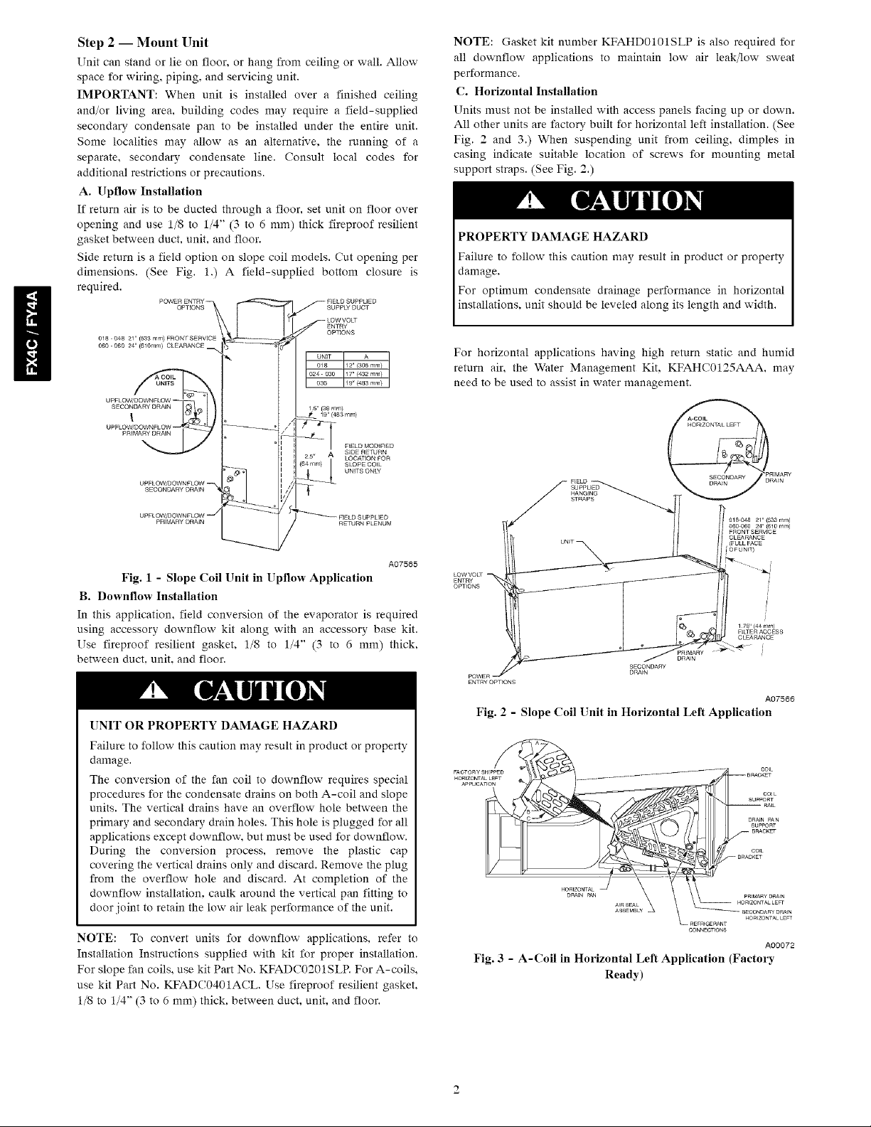
A. Upflow Installation
If return air is to be ducted through a floor, set unit on floor over
opening and use 1/8 to 1/4" (3 to 6 mm) thick fireproof resilient
gasket between duct, unit, and floor.
Side return is a field option on slope coil models. Cut opening per
dimensions. (See Fig. 1.) A field-supplied bottom closure is
required.
NOTE: Gasket kit number KFAHD0101SLP is also required for
all downflow applications to maintain low air leak/low sweat
performance.
C. Horizontal Installation
Units must not be installed with access panels facing up or down.
All other units are factory built for horizontal left installation. (See
Fig. 2 and 3.) When suspending unit from ceiling, dimples in
casing indicate suitable location of screws for mounting metal
support straps. (See Fig. 2.)
PROPERTY DAMAGE HAZARD
Failure to follow this caution may result in product or property
damage.
For optimum condensate drainage performance in horizontal
installations, unit should be leveled along its length and width.
For horizontal applications having high return static and humid
return air, the Water Management Kit. KFAHC0125AAA. may
need to be used to assist in water management.
A07565
Fig. 1 - Slope Coil Unit in Upflew Application
B. Downflow Installation
In this application, field conversion of the evaporator is required
using accessory downflow kit along with an accessory base kit.
Use fireproof resilient gasket, 1/8 to 1/4" (3 to 6 mm) thick,
between duct, unit, and floor.
UNIT OR PROPERTY DAMAGE HAZARD
Failure to follow this caution may result in product or property
damage.
The conversion of the fan coil to downflow requires special
procedures for the condensate drains on both A-coil and slope
units. The vertical drains have an overflow hole between the
primary and secondary drain holes. This hole is plugged for all
applications except downflow, but must be used for downflow.
During the conversion process, remove the plastic cap
covering the vertical drains only and discard. Remove the plug
from the overflow hole and discard. At completion of the
downflow installation, caulk around the vertical pan fitting to
door joint to retain the low air leak performance of the unit.
NOTE: To convert units for downflow applications, refer to
Installation Instructions supplied with kit for proper installation.
For slope fan coils, use kit Part No. KFADC0201SLP. For A-coils,
use kit Part No. KFADC0401ACL. Use fireproof resilient gasket.
1/8 to 1/4" (3 to 6 mm) thick, between duct, unit, and floor.
HANGING
STRAPS
ENTRY
OPTIONS
SECONDARY
DRA_N
DRA_N
Fig. 2 - Slope Coil Unit in Horizontal Left Application
CONNECTIONS
Fig. 3 - A-Coil in Horizontal Left Application (Factory
Ready)
018048 21" {833 ram)
060 060 24" (610 rnm)
FRONTSERVICE
CLEARANCE
{FULLFACE
[©FUNT
i
1 75" {44 ram)
F_LTE R ACCESS
CLEARANCE
A07566
cot L
SUPPORT
RAtL
DRAENPAN
SUPPORT
A00072
Page 3
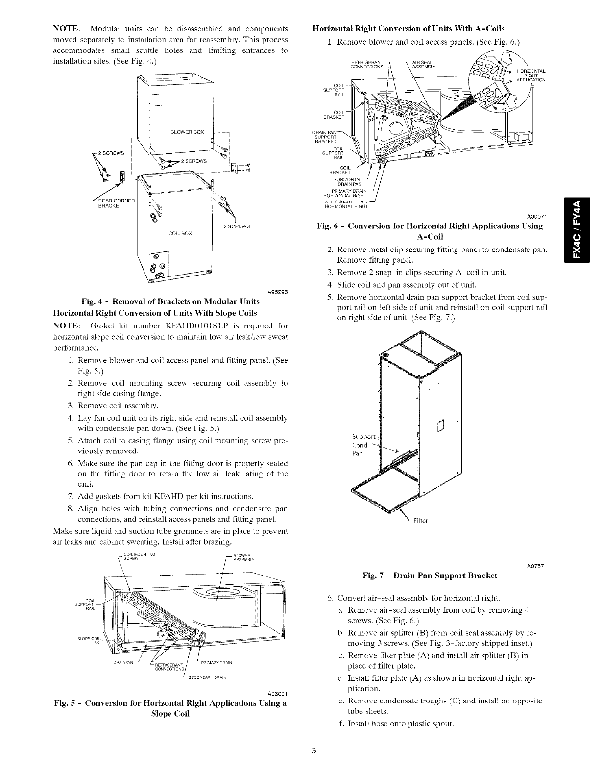
NOTE:Modularunitscanbedisassembledandcomponents
movedseparatelytoinstallationareaforreassembly.Thisprocess
accommodatessmallscuttleholesandlimitingentrancesto
installationsites.(SeeFig.4.)
BRACKET _ _
COIL BOX
Fig. 4 - Removal of Brackets on Modular Units
Horizontal Right Conversion of Units With Slope ('oils
NOTE: Gasket kit number KFAHD0101SLP is required for
horizontal slope coil conversion to maintain low air leak/low sweat
performance.
1. Remove blower and coil access panel and fitting panel. (See
Fig. 5.)
2. Remove coil mounting screw securing coil assembly to
right side casing flange.
3. Remove coil assembly.
4. Lay fan coil unit on its right side and reinstall coil assembly
with condensate pan down. (See Fig. 5.)
5. Attach coil to casing flange using coil mounting screw pre-
viously removed.
6. Make sure the pan cap in the fitting door is properly seated
on the fitting door to retain the low air leak rating of the
unit.
7. Add gaskets from kit KFAHD per kit instructions.
8. Align holes with tubing connections and condensate pan
connections, and reinstall access panels and fitting panel.
Make sure liquid and suction tube grommets are in place to prevent
air leaks and cabinet sweating. Install after brazing.
2 SCREWS
A95293
Horizontal Right Conversion of Units With A-Coils
1. Remove blower and coil access panels. (See Fig. 6.)
CONNECTIONS
SUPPORT
SUPPORT
SUPPORT
HORIZONTAL RIGHT
HORIZONTAL RIGHT
-AIR SEAL
APPLICATION
Fig. 6 - Conversion for Horizontal Right Applications Using
A-Coil
2. Remove metal clip securing fitting panel to condensate pan.
Remove fitting panel.
3. Remove 2 snap-in clips securing A-coil in unit.
4. Slide coil and pan assembly out of unit.
5. Remove horizontal drain pan support bracket from coil sup-
port rail on left side of unit and reinstall on coil support rail
on right side of unit. (See Fig. 7.)
i7 F[
A00071
A03001
Fig. 5 - Conversion for Horizontal Right Applications Using a
Slope Coil
A07571
Fig. 7 - Drain Pan Support Bracket
6. Convert air-seal assembly for horizontal right.
a. Remove air-seal assembly from coil by removing 4
screws. (See Fig. 6.)
b. Remove air splitter (B) from coil seal assembly by re-
moving 3 screws. (See Fig. 3-factory shipped inset.)
c. Remove filter plate (A) and install air splitter (B) in
place of filter plate.
d. Install filter plate (A) as shown in horizontal right ap-
plication.
e. Remove condensate troughs (C) and install on opposite
tube sheets.
f. Install hose onto plastic spout.
Page 4
7.Installhorizontalpanonrightsideofcoilassembly.
8.Slidecoilassemblyintocasing.Besurecoilbracketoneach
cornerofverticalpanengagescoilsupportrails.
9.Reinstall2 snap-inclipstocorrectlypositionandsecure
coilassemblyinunit.Besureclipwithlargeoffsetsisused
onrightsideofunittosecurehorizontalpan.
10.Removetwoovalfittingcapsfromtheleftsideofthecoil
doorandfittingpanel.
11.Removeinsulationknockoutsonrightsideofcoilaccess
panel.
12.Remove2 ovalcoilaccesspanelplugsandreinstallinto
holesonleftsideofcoilaccesspanelandfittingpanel.
13.Installcondensatepanfittingcaps(fromitem10)inthe
rightsideofthecoildoormakingsurethatthecapsnaps
andseatscleanlyonthebacksideofthecoildoor.Make
surenoinsulationinterfereswithseatingofthecap.
14.Reinstallaccessfittingpanels,aligningholeswithtubing
connectionsandcondensatepanconnections.Besuretore-
installmetalclipbetweenfittingpanelandverticalconden-
satepan.
Makesureliquidandsuctiontubegrommetsareinplacetoprevent
airleaksandcabinetsweating.
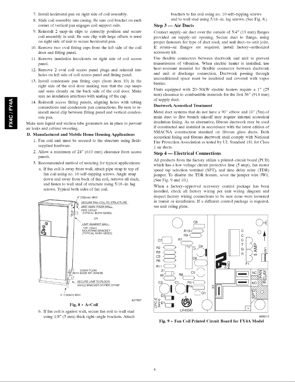
D. Manufactured and Mobile Home Housing Applications
1. Fan coil unit must be secured to the structure using field-
supplied hardware.
2. Allow a minimum of 24" (610 mm) clearance from access
panels.
3. Recommended method of securing for typical applications:
a. If fan coil is away from wall. attach pipe strap to top of
fan coil using no. 10 self-tapping screws. Angle strap
down and away from back of fan coil. remove all slack,
and fasten to wall stud of structure using 5/16-in. lag
screws. Typical both sides of fan coil.
4" (102mm) MAX
SECURE FAN COILTO STRUCTURE
UNIT AWAY FROM WALL
PIPE STRAP
(TYPICAL BOTH SIDES)
,%,. oR
_NST W,_
125" (3mm)
MOUNTING BRACKET
(TYPICAL BOTH SIDES)
brackets to fan coil using no. 10 self-tapping screws
and to wall stud using 5/16-in. lag screws. (See Fig. 8.)
Step 3 -- Air Ducts
Connect supply-air duct over the outside of 3/4" (19 mm) flanges
provided on supply-air opening. Secure duct to flange, using
proper fasteners for type of duct used, and seal duct-to-unit joint.
If return-air flanges are required, install factory-authorized
accessory kit.
Use flexible connectors between ductwork and unit to prevent
transmission of vibration. When electric heater is installed, use
heat-resistant material for flexible connector between ductwork
and unit at discharge connection. Ductwork passing through
unconditioned space must be insulated and covered with vapor
barrier.
Units equipped with 20-30kW electric heaters require a 1" (25
mm) clearance to combustible materials for the first 36" (914 mm)
of supply duct.
Ductwork Acoustical Treatment
Metal duct systems that do not have a 90 ° elbow and 10' (3m) of
main duct to first branch takeoff may require internal acoustical
insulation lining. As an alternative, fibrous ductwork may be used
if constructed and installed in accordance with the latest edition of
SMACNA construction standard on fibrous glass ducts. Both
acoustical lining and fibrous ductwork shall comply with National
Fire Protection Association as tested by UL Standard 181 for Class
1 air ducts.
Step 4 -- Electrical Connections
All products from the factory utilize a printed-circuit board (PCB)
which has a low voltage circuit protective fuse (5 amp), fan motor
speed tap selection terminal (SPT), and time delay relay (TDR)
jumper. To disable the TDR feature, sever the jumper wire JW1.
(See Fig. 9 and 10.)
When a factory-approved accessory control package has been
installed, check all factory wiring per unit wiring diagram and
inspect factory wiring connections to be sure none were loosened
in transit or installation. If a different control package is required.
see unit rating plate.
DOWN FLOW
(KFACB)
_._ SECURE UNtTTO FLOOR
ANGLE BRACKET OR PIPE STRAP
_=
4" (102ram) MAX
Fig. 8 - A-Coil
b. If fan coil is against wall, secure fan coil to wall stud
using 1/8" (3 mm) thick right-angle brackets. Attach
A07567
R2
R3
03
[16
[111
Fig. 9 - Fan Coil Printed Circuit Board for FY4A Model
Page 5

C2
IO B_gO{ITd3]
A05181
Fig. 10 - Fan Coil Printed Circuit Board
for FX4C Model
PROPERTY DAMAGE HAZARD
Failure to follow this caution may result in product or
property damage.
If a disconnect switch is to be mounted on unit, select a
location where drill or fastener will not contact electrical or
refrigerant components.
Before proceeding with electrical connections, make certain that
supply voltage, frequency, phase, and ampacity are as specified on
the unit rating plate. See unit wiring label for proper field high-
and low-voltage wiring. Make all electrical connections in
accordance with the NEC and any local codes or ordinances that
may apply. Use copper wire only.
The unit must have a separate branch electric circuit with a
field-supplied disconnect switch located within sight from, and
readily accessible from, the unit.
On units with a factory-installed disconnect with pull-out
removed, service and maintenance can be safely performed on only
the load side of the control package.
ELECTRICAL SHOCK HAZARD
Failure to follow this warning could result in personal injury or
death.
Field wires on the line side of the disconnect found in the fan coil
unit remain live, even when the pull-out is removed. Service and
maintenance to incoming wiring cannot be performed until the
main disconnect switch (remote to the unit) is turned off.
A. Line Voltage Connections
If unit will contain accessory electric heater, remove and discard
power plug from fan coil and connect male plug from heater to
female plug from unit wiring harness. (See Electric Heater
Installation Instructions.)
For units without electric heater:
1. Connect 208/230v power leads from field disconnect to yel-
low and black stripped leads.
2. Connect ground wire to unit ground lug.
NOTE: Units installed without electric heat should have a
field-supplied sheet metal block-off plate covering the heater
opening. This will reduce air leakage and formation of exterior
condensation.
B. 24-v Control System
Connection To Unit
Wire low voltage in accordance with wiring label on the blower.
(See Fig. 11 through 16.) Use no. 18 AWG color-coded, insulated
(35°C minimum) wire to make the low-voltage connections
between the thermostat, the unit, and the outdoor equipment. If the
thermostat is located more than 100' (30 m) from the unit (as
measured along the low-voltage wire), use no. 16 AWG
color-coded, insulated (35 _C minimum) wire. All wiring must be
NEC Class 1 and must be separated from incoming power leads.
THERMOSTAT (CONTROL)
FAN COtk
_::_ G_ G
[]
] ......
W2
W3
E
Fig. 11 - Wiring Layout Air Conditioning [;nit
(Cooling Only)
A94058
Page 6

THERMOSTAT
] .............
WriT WH3 W2
BLU W3
FAN COIL
(CONTROL)
...............R
FAN COl L
(CONTROL)
R
G
C:5_ R
_-Nc L:_
H_ W2
BL--UoSTS 1_ .........
HEAT PUMP
(CONTROL)
c
_v2
C AIR COND.
] ............
Fig. 12 - Wiring Layout Air Conditioning Unit
(Cooling and 1-Stage Heat)
THERMOSTAT (CONTROL) HEAT PUMP
_R
.........................Z_, GRY G
] .........
] .........
...........w:
FAN COIL
CONTRL)
R
C
[]
[]
_77x
5:5 z_
Fig, 13 - Wiring Layout Heat Pump Unit
(Cooling and 2-Stage Heat with
No Outdoor Thermostat)
THERMOSTAT (CONTROL) HEAT PUMP
-- -- (CONTROL)
FAN COiL
W2
O
Y
R
[] ..........................................G
[] ............. ........................................................c
_- _-,WHT W
] ..........
] ............. O
[Z]__ Z:a_y
A94059
A94060
E VlO
[]
EMERGENCY HEAT RELAY
Fig. 15 - Wiring Layout Heat Pump Unit
(Cooling and 2-Stage Heat with 2
Outdoor Thermostats)
THERMOSTAT FAN COIL HEAT PUMP
] ................................................... .............
] .........
(CONTROL) (CONTROL)
o
Y
A94062
[]
A03088
Fig. 16 - Wiring Layout Heat Pump Unit
(Cooling and 2-Stage Heat for Manufactured Housing)
Refer to outdoor unit wiring instructions for any additional wiring
procedure recommendations.
Transformer Information
Transformer is factory-wired for 230v operation. For 208v
applications, disconnect the black wire from the 230v terminal on
transformer and connect it to the 208v terminal. (See Fig. 17.)
Fig. 14 - Wiring Layout Heat Pump Unit
(Cooling and 2-Stage Heat with
1 Outdoor Thermostat)
A94061
Page 7

RED
Fig. 17 - Transformer Connections
Heater Staging
PROPERTY DAMAGE HAZARD
Failure to follow this caution may result in product or
property damage.
If W2, W3, and E on any 3 stage heater (18, 20. 24, or
30kW) are individually connected as with outdoor
thermostats or any other situation, emergency heat relay must
be used. This relay is in kit Part No. KHOT0201SEC and is
normally used with kit Part No. KHAOT0301FST for 2
outdoor thermostat systems.
NOTE: Use UL-listed conduit and conduit connector for
connecting supply wire(s) to unit to obtain proper grounding.
Grounding may also be accomplished by using grounding lugs
provided in control box.
E. Minimum CFM and Motor Speed Selection
Units with or without electric heaters require a minimum CFM.
Refer to the unit wiring label to ensure that the fan speed selected is
not lower than the minimum fan speed indicated.
FY4A fan speed selection is done at the fan relay printed-circuit
board. To change motor speeds, disconnect fan lead used on relay
terminal (SPT) and replace with motor speed tap desired. (See Fig.
18.) Save insulating cap and place on motor lead removed from
relay.
A05182
FAN RELAY_
The controls are factory circuited for single-stage operation. For
2-stage operation, use outdoor thermostat kit Part No.
KHAOT0301FST. and for 3-stage use both kits Part No.
KHAOT0201SEC and KHAOT0301FST.
When 2 stages are desired, cut W3 at the W2 wire nut. strip and
reconnect per the thermostat kit instruction. (See Fig. 14.) When 3
stages are desired, cut the W2 wire nut off and discard. Strip W2,
W3, and E and reconnect per thermostat kit instructions. (See Fig.
15.)
NOTE: When 3 stages are used or anytime the E terminal is not
tied to W2, the emergency heat relay, part of outdoor kit Part No.
KHAOT0201SEC must be used.
C. Manufactured Housing
In manufactured housing applications, the Code of Federal
Regulations, Title 24, Chapter XX, Part 3280.714 requires that
supplemental electric heat be locked out at outdoor temperatures
above 40°F (4°C), except for a heat pump defrost cycle. Refer to
Fig. 16 for typical low voltage wiring with outdoor thermostat.
D. Ground Connections
ELECTRICAL SHOCK HAZARD
Failure to follow this warning could result in personal injury
or death.
According to NEC, ANSI/NFPA 70, and local codes, the
cabinet must have an uninterrupted or unbroken ground to
minimize personal injury if an electrical fault should occur.
The ground may consist of electrical wire or metal conduit
when installed in accordance with existing electrical codes. If
conduit connection uses reducing washers, a separate ground
wire must be used.
A97529
Fig. 18 - Fan Coil Relay and Speed Tap Terminal for FY4A
Models
NOTE: In low static applications, lower motor speed tap should
be used to reduce possibility of water being blown off coil.
Most units have 3 motor speed taps. Low speed (red) is designed
for mismatched outdoor unit applications. Medium speed (blue) is
designed for straight matched operations. High speed (black) is
used with high external static duct systems of straight matched
systems.
The fan speed selection on the FX4C models is done at the motor.
To change motor speeds, disconnect fan lead from terminal 2 and
move to desired speed tap; Low speed (one), Medium (two), and
High (three).
Step 5 -- Refrigerant Tubing Connection and
Evacuation
Use accessory tubing package or field-supplied tubing of
refrigerant grade. Suction tube must be insulated. Do not use
damaged, dirty, or contaminated tubing because it may plug
refrigerant flow-control device. ALWAYS evacuate the coil and
field-supplied tubing to 500 microns before opening outdoor unit
service valves.
Page 8

PRODUCTDAMAGEHAZARD
Failuretofollowthiscautionmayresultin productor
propertydamage.
AbrazingshieldMUSTbeusedwhentubingsetsarebeing
brazedtotheunitconnectionstopreventdamagetotheunit
surfaceandcondensatepanfittingcaps.
Unitshavesweatsuctionandliquidtubeconnections.Make
suctiontubeconnectionfirst.
1.Cuttubingtocorrectlength.
2.Inserttubeintosweatconnectiononunituntilitbottoms.
3.Brazeconnectionusingsilverbearingornon-silverbearing
brazingmaterials.Donotusesolder(materialswhichmelt
below800°F/ 427°C). Consult local code requirements.
4. Evacuate coil and tubing system to 500 microns using deep
vacuum method.
PRODUCT DAMAGE HAZARD
Failure to follow this caution may result in product or
property damage.
Wrap a wet cloth around rear of fitting to prevent damage to
TXV and factory-made joints.
UNIT OR PROPERTY DAMAGE HAZARD
Failure to fnllow this caution may result in product or
property damage.
The conversion of the fan coil to downflow requires special
procedures for the condensate drains on both A-coil and
slope units. The vertical drains have an overflow hole
between the primary and secondary drain holes. This hole is
plugged for all applications except downflow, but must be
used for downflow. During the conversion process, remove
the plastic cap covering the vertical drains only and discard.
Remove the plug from the overflow hole and discard. At
completion of the downflow installation, caulk around the
vertical pan fitting to door joint to retain the low air leak
performance of the unit.
Units are equipped with primary and secondary 3/4-in. FPT drain
connections. For proper condensate line installations see Fig. 1, 2.
3, 5 and 6. To prevent property damage and achieve optimum
drainage performance. BOTH primary and secondary drain lines
should be installed and include properly-sized condensate traps.
(See Fig. 19 and 20.) Factory-approved condensate traps are
available. It is recommended that PVC fittings be used on the
plastic condensate pan. Finger-tighten plus 1-1/2 turns. Do not
over-tighten. Use pipe dope.
Step 6 -- Refrigerant Flow-Control Device
Tire FX4C and FY4A are equipped with PuronCR) refrigerant TXV.
Use outdoor units designed for Purnn(A) refrigerant only.
PRODU('T OPERATION HAZARD
Failure to follow this caution may result in improper product
operation.
If using a TXV in conjunction with a single-phase
reciprocating compressor, a compressor start capacitor and
relay are required. Consult outdoor unit pre-sale literature for
start assist kit part number.
Step 7 -- Condensate Drains
To connect drains, the cap openings must be removed. Use a knife
to start the opening near the tab and using pliers, pull the tab to
remove the disk. Clean the edge of the opening if necessary and
install the condensate line. Finally caulk around the lines where
they exit the fitting to retain the low leak rating of the unit.
PROPERTY DAMAGE HAZARD
Failure to follow this caution may result in product or
property damage.
Shallow running traps are inadequate and DO NOT allow
proper condensate drainage. (See Fig. 21.)
UNIT
f
2" MIN
(51 mm)
A03002
Fig. 19 - Recommended Condensate Trap
Page 9

B. Humidifier
Connect humidifier and humidistat to fan coil unit as shown in Fig.
23 and Fig. 24. The cooling lockout relay is optional.
s
PANEL
- SECONDAR Y DRAIN W_TH
AppRoPREATE TRAp REQUIRED
(USE FACTORY KIT OR
PRIMARY TRAP RE U[RE_ FIELD SUPPUED TRAP)
(USE FACTORY KIT OR
FIELD SUPPUED TRAP OF
SUFFICIENT DEPTH
STANDARD P TRAPS ARE
NOT $UFF[C[ENT SEE
FIGURE OF RECOMMENDED
CONDENSATE TRAP)
A03003
Fig. 20 - Condensate Trap and Unit
DO NOT USE SHALLOW RUNN{NG TRAPS!
A03013
Fig. 21 - Insufficient Condensate Trap
NOTE: When connecting condensate drain lines, avoid blocking
filter access panel, thus preventing filter removal. After connection,
prime both primary and secondary condensate traps.
NOTE: If unit is located in or above a living space where damage
may result from condensate overflow, a field-supplied, external
condensate pan should be installed underneath the entire unit. and a
secondary condensate line (with appropriate trap) should be run
from the unit into the pan. Any condensate in this external
condensate pan should be drained to a noticeable place. As an
alternative to using an external condensate pan, some localities
may allow the use of a separate 3/4" (19 mm) condensate line (with
appropriate trap) to a place where the condensate will be
noticeable. The owner of the structure must be informed that when
condensate flows from the secondary drain or external condensate
pan, the unit requires servicing or water damage will occur.
Install traps in the condensate lines as close to the coil as possible.
(See Fig. 20.) Make sure that the outlet of each trap is below its
connection to the condensate pan to prevent condensate from
overflowing the drain pan. Prime all traps, test for leaks, and
insulate traps if located above a living area. Condensate drain lines
should be pitched downward at a minimum slope of 1" (25 mm)
for every 10' (3 m) of length. Consult local codes for additional
restrictions or precautions.
Step 8 -- Accessories
A. Electronic Air Cleaner
The Electronic Air Cleaner may be connected to fan coil as shown
in Fig. 22. This method requires a field supplied transformer. See
Electronic Air Cleaner literature for kit requirements.
CONTROL BOARD
2?gAcFANRELAY I R G T C C C
NONCIIlllll
FROM MOLEX
PLUGAND
TRANSFORMER
(IN UNIT)
A03011
Fig. 22 - WMng Layout of Electronic Air Cleaner to Fan Coil
for FY4A Models Only
THERMOSTAT
FAN COIL
(CONTROL)
HEAT PUMP
(CONTR....OL)
R
.............................G
] .............
W3
[]
[]
i
i
] .............
......... i.......... i i
FAN HUMtDtFIE , RELAY ,,
W2
O
Y
....
--L--'
,JJ , HUMIDtSTAT
A95294
Fig. 23 - Wiring Layout of Humidifier to Heat Pump
Page 10

THERMOSTAT (CONTROL)
FAN COIL
R
W2
W3
E
i
[] i
-- i i
i i
C AIRCOND
START-UP PROCEDURES
Refer to outdoor unit Installation Instructions for system start-up
instructions and refrigerant charging method details.
UNIT COMPONENT HAZARD
Failure to follow this caution may result in product damage.
Never operate unit without a filter. Damage to blov:er motor
or coil may result. Factory authorized filter kits must be used
when locating the filter inside the unit. For those applications
where access to an internal filter is impractical, a
field-supplied filter must be installed in the return duct
system.
LU1
Ag5295
Fig. 24 - Wiring Layout of Humidifier to Fan Coil
With Electric Heat
Step 9 -- Sequence of Operation
A. Continuous Fan
Thermostat closes R to G. G energizes fan relay on PCB which
completes circuit to indoor blower motor. When G is de-energized.
there is a 90-sec delay before relay opens.
B. Cooling Mode
Thermostat energizes R to G. R to Y, and R to O (heat pump only).
G energizes fan relay on PCB which completes circuit to indoor
blower motor. When G is de-energized, there is a 90-sec delay
before fan relay opens.
C. Heat Pump Heating with Auxiliary Electric Heat
Thermostat energizes R to G. R to Y, and R to W. G energizes fan
relay on PCB which completes circuit to indoor blower motor. W
energizes electric heat relay(s) which completes circuit to heater
element(s). When W is de-energized, electric heat relay(s) open,
turning off heater elements. When G is de-energized there is a
90-sec delay before fan relay opens.
D. Electric Heat or Emergency Heat Mode
Thermostat closes R to W. W energizes electric heat relay(s) which
completes circuit to heater element(s). Blower motor is energized
through normally closed contacts on fan relay. When W is
de-energized, electric heat relay(s) opens.
CARE AND MAINTENANCE
To continue high performance and minimize possible equipment
failure, it is essential that periodic maintenance be performed on
this equipment. Consult your local dealer as to the proper
frequency of maintenance contract.
The ability to properly perform maintenance on this equipment
requires certain mechanical skills and tools. If you do not possess
these, contact your dealer fnr maintenance. The only consumer
service recommended or required is filter replacement or cleaning
on a monthly basis.
10
Page 11

AIRFLOW PERFORMANCE TABLES
Table 1 - Airflow Performance (CFM)
FX4C BLOWER TOTAL EXTERNAL STATIC PRESSURE
SIZE SPEED 0.10 0.20 0.30 0.40 0.50 0.60
High 666 619 566
018 Medium } 578 538 499
Low 614 572 530 486 441 396
High } 905 868 630 792 753
024 Medium 823 786 747 707 665 622
Low 633 583 533 482 431 378
High 1130 1097 1063 1028 992 955
030 Medium 1033 1000 965 928 888 846
Low 840 802 760 713 663 609
High 2_3 1354 1308 1257 1204
036 Medium 1282 1238 1192 1142 1090 1036
Low 1168 1118 1067 1014 959 903
High 1578 1533 1480 1420 1353
042 Medium 1479 1437 1392 1344 1293 1240
Low 1303 1258 1211 1161 1108 1054
High 1805 1772 1739 1704 1669 1632
048 Medium 1652 1617 1581 1543 1504 1463
Low 1458 1418 1377 1335 1292 1248
High 202 1989 1954 1916 1878
060 Medium 1799 1766 1731 1695 1658 1618
Low 1667 1633 1596 1558 1517 1475
- Airflow outside 450 cfm/ton.
NOTES:
1. Airflow based upon dry coil at 230v with factory-approved filter and electric heater (2 element heater sizes 018 through 036, 3 element
heater sizes 042 through 060). Airflow at 208 volts is approximately 10% lower for FY4A models. For FX4C models, airflow at 208 volts
is approximately the same as 230 volts because the X13 motor is a constant torque motor. The torque doesn't drop off at the speeds the
motor operates.
2. To avoid potential for condensate blowing out of drain pan prior to making drain trap:
Return static pressure must be less than 0.40 in. wc.
Horizontal applications of 042 - 060 sizes must have supply static greater than 0.20 in. wc.
3. Airflow above 400 cfm/ton on 048-060 size could result in condensate blowing off coil or splashing out of drain pan.
FY4A BLOWER TOTAL EXTERNAL STATIC PRESSURE
SIZE SPEED 0.10 0.20 0.30 0.40 0.50 0.60
018 High _ _ , _90::[: 607 504
024 High 99'1 9_ 860 793 724
Low 633 620 588 538 468 380
Low 878 616 754 666 614
030 High 1070 1032 978 908 822 721
036 High 1352 1316 1273 1223 1167 1103
042 Medium 1576 1540 1488 1421 1338 1239
048 Medium !88 i763 1690 1611 1527 1436
060 Medium 1959 1898 1829 1750 1663 1566
Low 910 888 849 791 715 621
Low 1137 1112 1081 1043 998 946
High 72 1521 1426 1316
Low 1388 1367 1330 1278 1209 1124
High 1743 1659 1571 1479
Low 1625 1584 1531 1465 1387 1296
High 1965 1875 1778 1674
Low 1748 1709 1659 1598 1525 1442
Table 2 - Air Delivery Performance Correction Component Pressm-e Drop (in. wc) at Indicated Airflow (Dry to Wet Coil)
FY, FX CFM
SIZE 500 600 700 800 900 1000 1100 1200 1300 1400 1500 1600 1700 1800 1900 2000
018 0.034 0.049 0.063 ..........................
024 0.016 0.027 0.038 0.049 0.059 ......................
030 ...... 0.049 0.059 0.070 0.080 ..................
036 .......... 0.055 0.064 0.073 0.081 ..............
042 .............. 0.049 0.056 0.063 0.070 ..........
048 .................. 0.038 0.043 0.049 0.054 0.059 ....
060 ...................... 0.027 0.031 0.035 0.039 0.043
Table 3 - Factol3,-Installed Filter Static Pressure Drop (in. wc)
F¥, FX
SIZE 400 1600 1800 2000
018 0.020 -
024, 030 - - -
036, 042,048 - 0.120 0.152 -
060 - 0.086 0.105 0.130
HEATER HEATER
ELEMENTS ELEMENTS
0 0 +.02 0 0 +.04
1 3, 5 +.01 2 8, 10 +.02
2 6,10 0 3 9,15 0
3 9, 15 .02 4 20 .02
4 20 .04 6 18, 24, 30 .10
kW PRESSURE kW PRESSURE
600 800 1000 1200 1400
0.044 0.075 - -
0.022 0.048 0.072 0.100
- - 0.051 0.070 0.092
Table 4 - Electric Heater Static Pressure Drop (in. wc)
FX, FY FX, FY
018 - 036 042 - 060
EXTERNAL STATIC EXTERNAL STATIC
CORRECTION CORRECTION
CFM
11
Page 12

PURON® (R-410A) QUICK REFERENCE GUIDE
• Puron refrigerant operates at 50-70 percent higher pressures than R-22. Be sure that servicing equipment and replacement
components are designed to operate with Puron refrigerant.
• Puron refrigerant cylinders are rose colored.
• Recovery cylinder service pressure rating must be 400 psig, DOT 4BA400 or DOT BW400.
• Puron refrigerant systems should be charged with liquid refrigerant. Use a commercial type metering device in the manifold hose
when charging into suction line with compressor operating
• Manifold sets should be 700 psig high side and 180 psig low side with 550 psig low-side retard.
• Use hoses with 700 psig service pressure rating.
• Leak detectors should be designed to detect HFC refrigerant.
• Puron refrigerant, as with other HFCs, is only compatible with POE oils.
• Vacuum pumps will not remove moisture from oil.
• Do not use liquid-line filter driers with rated working pressures less than 600 psig.
• Do not leave Puron refrigerant suction line filter driers in line longer than 72 hours.
• Do not install a suction-line filter drier in liquid line.
• POE oils absorb moisture rapidly. Do not expose oil to atmosphere.
• POE oils may cause damage to certain plastics and roofing materials.
• Wrap all filter driers and service valves with wet cloth when brazing.
• A factory approved liquid-line filter drier is required on every unit.
• Do NOT use an R-22 TXV.
• If indoor unit is equipped with a R-22 TXV or piston metering device, it must be changed to a hard-shutoff Puron refrigerant TXV.
• Never open system to atmosphere while it is under a vacuum.
• When system must be opened for service, recover refrigerant, evacuate then break vacuum with dry nitrogen and replace filter driers.
Evacuate to 500 microns prior to recharging.
• Do not vent Puron refrigerant into the atmosphere.
• Do not use capillary tube coils.
• Observe all warnings, cautions, and bold text.
• All indoor coils must be installed with a hard-shutoff Puron refrigerant TXV metering device.
Copyright 2007 CAC / BDP • 7310 W. Morris St. • indianapolis, IN 46231 Printed in US.A. Edition Date: 06/07
Manufacturer reserves the right to change_ at any time_ specifications and designs without notice and without obligations.
12
Catalo_ No: IM-FX4C-03
Replaces: IM-FX4C-02
 Loading...