

Carrier 50EJQ, EWQ024, 028, 50EJQ024, 50EJQ028 Installation, Start-up And Service Instructions Manual
...Page 1
Installation, Start-Up and
Service Instructions
CONTENTS
Page
SAFETY CONSIDERATIONS ................ 1
INSTALLATION ............................ 1-20
Step 1 — Provide Unit Support ............. 1
• ROOF CURB
• ALTERNATE UNIT SUPPORT
Step 2 — Rig and Place Unit ............... 5
• POSITIONING
• ROOF MOUNT
Step 3 — Field Fabricate Ductwork ......... 5
Step 4 — Make Unit Duct Connections ...... 5
Step5—TrapCondensate Drain ........... 7
Step 6 — Controls Options ................. 7
• FEATURES WITH THERMOSTAT CONTROL
OF UNIT
• FEATURES WITH SENSOR CONTROL OF
UNIT (Stand-Alone Applications)
• FEATURES WITH SENSOR CONTROL OF
UNIT (Network Applications)
Step 7 — Make Electrical Connections ...... 9
• POWER WIRING
• FIELD POWER SUPPLY
• FIELD CONTROL WIRING
Step 8 — Make Outdoor-Air Inlet
Adjustments .............................. 14
• ECONOMIZER
• ECONOMIZER SETTINGS
Step 9 — Position Power Exhaust/
Barometric Relief Damper Hood ........... 18
Step 10 — Install Accessories .............. 18
START-UP ................................21-28
SERVICE ..................................29-33
TROUBLESHOOTING ......................34-38
START-UP CHECKLIST ...............CL-1, CL-2
SAFETY CONSIDERATIONS
Installation and servicing of air-conditioning equipment
can be hazardous due to system pressure and electrical components. Only trained andqualifiedservice personnel should
install, repair, or service air-conditioning equipment.
Untrained personnel can perform basic maintenance functions of cleaning coils and filters and replacing filters. All
other operations should be performed by trained service personnel. When working on air-conditioning equipment, observe precautions in the literature, tags and labels attached
to the unit, and other safety precautions that may apply.
Follow all safety codes. Wearsafety glasses and work gloves.
Use quenching cloth for unbrazing operations. Have fire extinguishers available for all brazing operations.
Before performing service or maintenance operations on
unit, turn off main power switch to unit. Electrical shock
could cause personal injury.
INSTALLATION
Step 1 — Provide Unit Support
All panels must be in place when rigging. Unit is not
designed for handling by fork truck.
ROOF CURB — Assemble and install accessory roof curb
in accordance with instructions shipped with the curb.
Accessory roof curb and information required to field fabricate a roof curb or horizontal adapter are shown in Fig. 1.
Install insulation, cant strips, roofing, and counter flashing
as shown. Ductwork can be secured to roof curb before unit
is set in place.
IMPORTANT: The gasketing of the unit to the roof
curb is critical for a leak-proof seal. Install gasket supplied with the roof curb as shown in Fig. 1. Improperly applied gasket can result in air leaks and poor unit
performance.
Curb should be level. This is necessary to permit unit drain
to function properly. Unit leveling tolerance is shown in
Fig 1. Refer to Accessory Roof Curb Installation Instructions for additional information as required. When accessory roof curb is used, unit may be installed on class A, B,
or C roof covering material.
ALTERNATE UNIT SUPPORT — When the curb or adapter
cannot be used, support unit with sleepers using unit curb or
adapter support area. If sleepers cannot be used, support long
sides of unit (refer to Fig. 2 and 3) with a minimum number
of equally spaced 4-in. x 4-in. pads. 50EJQ,EWQ024 and
028 units require 3 pads on each side. Unit may sag if supported by corners only.
50EJQ,EWQ024,028
Single-Package Rooftop
Heat Pump Units
Manufacturer reserves the right to discontinue, or change at any time, specifications or designs without notice and without incurring obligations.
Book 1
Tab 5a
PC 111 Catalog No. 535-002 Printed in U.S.A. Form 50EJQ,EWQ-2SI Pg 1 8-97 Replaces: 50EJQ,EWQ-1SI
Page 2
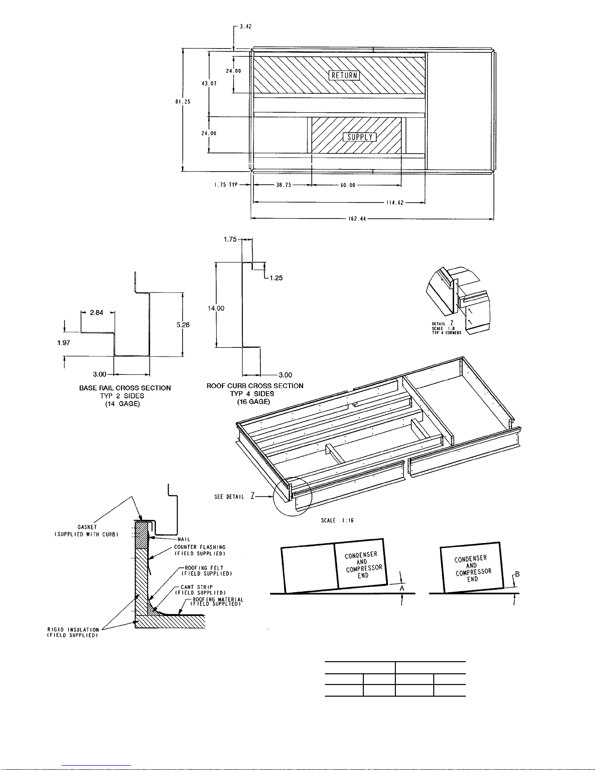
NOTES:
1. Unless otherwise specified,alldimensions are to outside of part.
2. Roof curb accessory is shipped disassembled.
3. All roof curb parts are to be 16 ga galvanized steel.
4. Dimensions are in inches.
Fig. 1 — Roof Curb (Sizes 024 and 028)
UNIT LEVELING TOLERANCES DIMENSIONS*
(Degrees and Inches)
AB
Deg. in. Deg. in.
1.0 2.9 .50 .75
*From edge of unit to horizontal.
NOTE: To prevent standing water in the drain pan of the indoor section
and the heat exchangers, UNIT CAN ONLY BE PITCHED AS SHOWN.
2
Page 3
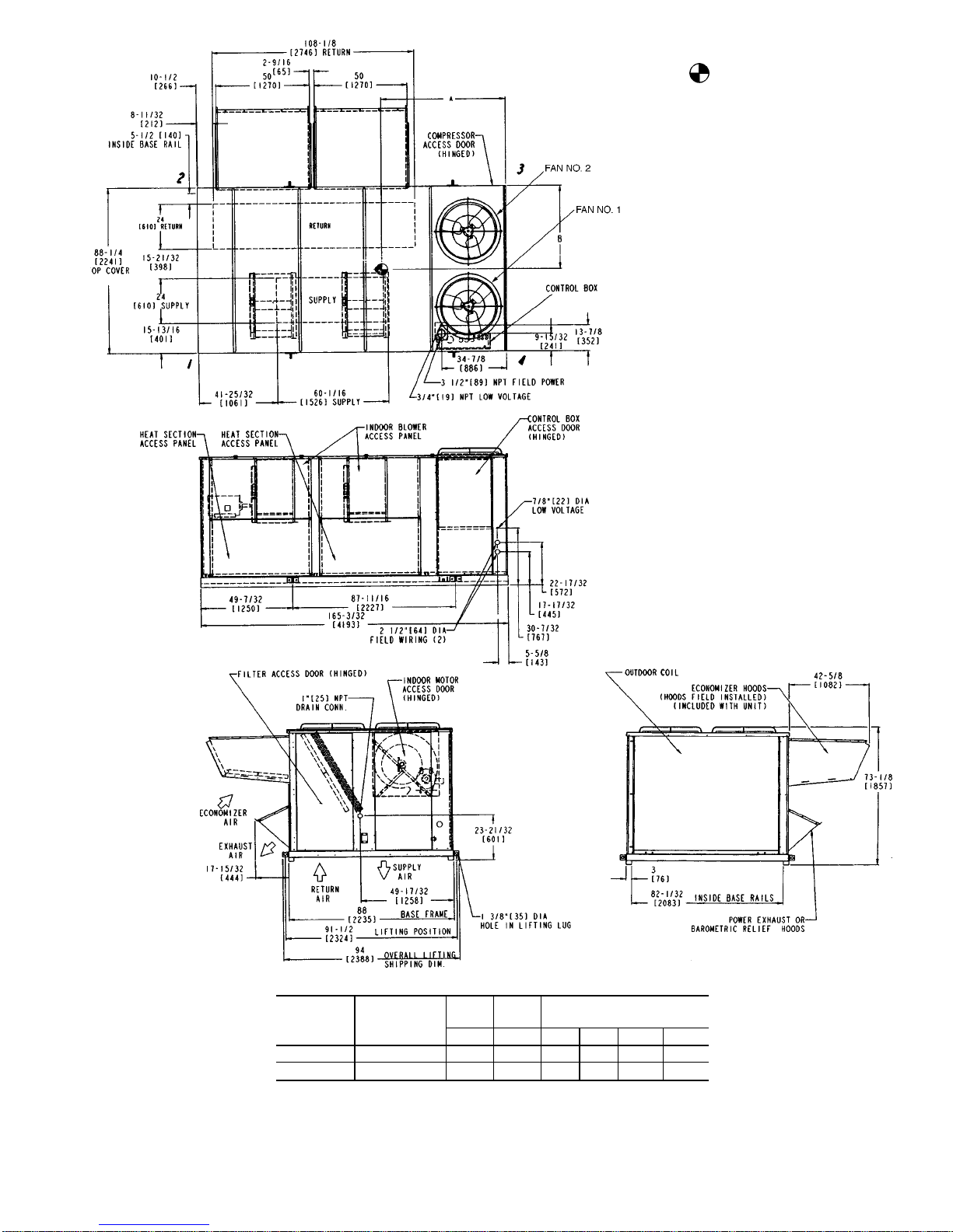
NOTES:
1. Weights include economizer (Std)
2. Center of gravity.
3. Do not locate adjacent units with discharge facing economizer inlet. Minimum clearances to be:
Adjacent Units: 158-09
Top of Units: No overhang
Outdoor Coil: 48-09
Economizer Side: 68-09
Filter Access Side: 108-09 (for removal of evaporator coil)
4. For smaller service and operational
clearances, contact Carrier Application Engineering department.
5. Bottom ducts designed to be attached
toaccessoryroofcurb.Ifunitismounted
on dunnage, it is recommended the
ducts be supported by cross bracesas
done on accessory roof curb.
6. Dimensions are in inches. Dimensions in [ ] are in millimeters.
7. For units with electric heat, a fieldsupplied 90° elbow must be installed
in the supply ductwork below the unit
discharge.
UNIT SIZE
50EJQ
OPERATING
WEIGHT
(lb)
AB
CORNER WEIGHT
(lb)
ft-in. ft-in. 1 2 3 4
024 4168 5-7
3
⁄83-75⁄8843 859 1245 1222
028 4168 5-7
3
⁄83-75⁄8843 859 1245 1222
Fig. 2 — Base Unit Dimensions, 50EJQ024 and 028
3
Page 4
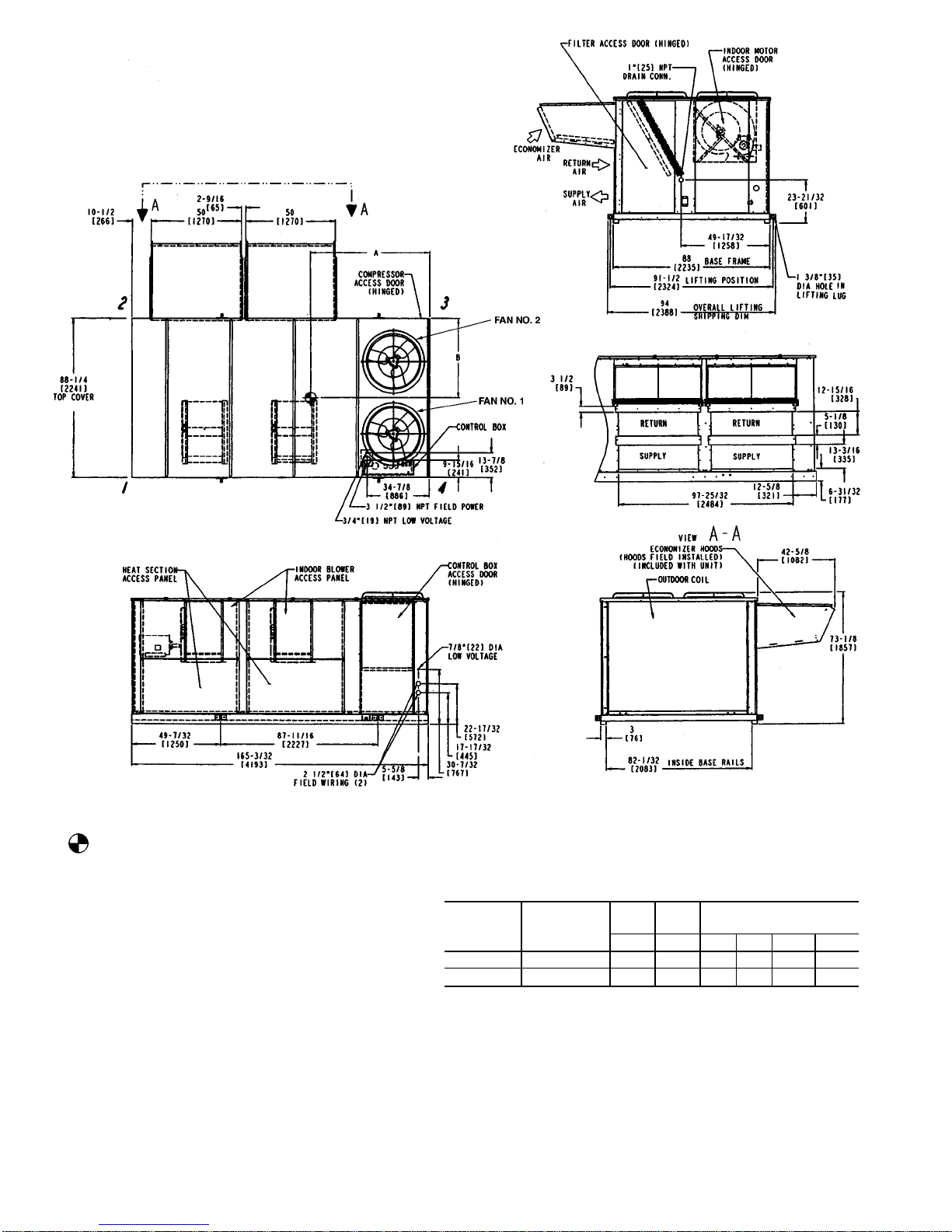
NOTES:
1. Weights include economizer (Std)
2. Center of gravity.
3. Do not locate adjacentunitswith discharge facing economizer inlet. Minimum clearances to be:
Adjacent Units: 158-09
Top of Units: No overhang
Outdoor Coil: 48-09
Economizer Side: 68-09
Filter Access Side: 108-09 (for removal of evaporator
coil)
4. For smaller service and operational clearances, contact Carrier Application Engineering department.
5. Dimensions are in inches. Dimensions in [ ] are in
millimeters.
6. For units equipped with electric heat, a field-supplied
90° elbow must be installed in the supply ductwork below the unit discharge.
7. For side-supply/return applications, a single return and
supply ductwork connection is recommended for covering both return and both supply openings.
UNIT SIZE
50EWQ
OPERATING
WEIGHT
(lb)
AB
CORNER WEIGHT
(lb)
ft-in. ft-in. 1 2 3 4
024 4168 5-7
3
⁄83-75⁄8843 859 1245 1222
028 4168 5-7
3
⁄83-75⁄8843 859 1245 1222
Fig. 3 — Base Unit Dimensions, 50EWQ024 and 028
4
Page 5
Step 2 — Rig and Place Unit— Inspect unit for trans-
portation damage. File any claim with transportation agency.
Keep unit upright, and do not drop. Use spreader bars over
unit to prevent sling or cable damage. Rollers may be used
to move unit across a roof. Level by using unit frame as a
reference; leveling tolerance is shown in Fig. 1. See Fig. 4
for additional information. Unit weight is shown in Table 1.
NOTE: On retrofit jobs, ductwork may be attached to old
unit instead of roof curb. Be careful not to damage ductwork
when removing unit. Attach existing ductwork to roof curb
instead of unit.
Four lifting lugs are provided on the unit base rails as shown
in Fig. 4. Refer to rigging instructions on unit.
POSITIONING — Provide clearance around and above unit
for airflow, safety, and service access (Fig. 2 and 3).
Do not install unit in an indoor location. Do not locate air
inlets near exhaust vents or other sources of contaminated
air.
Although unit is weatherproof, guard against water from
higher level runoff and overhangs.
ROOF MOUNT — Check building codes for weight distribution requirements.
Step 3 — Field Fabricate Ductwork — Secure all
ducts to building structure. Use flexible duct connectors between unit and ducts as required. Insulate and weatherproof
all external ductwork, joints, and roof openings with counter
flashing and mastic in accordance with applicable codes.
Ducts passing through an unconditioned space must be
insulated and covered with a vapor barrier.
To attach ductwork to roof curb, insert ductwork approximately 10 to 11 in. up into the curb. Connect ductwork to
14-gage roof curb material using sheet metal screw driven
from inside the duct.
For vertical supply and return units, tools or parts could
drop into ductwork and cause an injury. Install a
90 degree turn in the return ductwork between the unit
and the conditioned space. If a 90 degree elbow cannot
be installed, then a grille of sufficient strength and density should be installed to prevent objects from falling
into the conditioned space. Due to electric heater, supply duct will require 90 degree elbow.
The units with electric heat require a 1-in. clearance for
the first 24 in. of ductwork.
NOTE: A 90-degree elbow must be provided in the duct-
work to comply with UL (Underwriters’ Laboratories) codes
for use with electric heat.
Outlet grilles must not lie directly below unit discharge.
Step 4 — Make Unit Duct Connections
50EJQ UNITS — Unit is shipped for through-the-bottom
duct connections. Ductwork openings are shown in Fig. 2.
Attach all ductwork to roof curb. Air distribution is shown
in Fig. 5. Refer to installation instructions shipped with accessory roof curb for more information.
50EWQ UNITS — Remove shipping covers from supply
and return air openings. Attach field-supplied ductwork to
unit. Use a single duct over both return openings and a single
duct over both supply openings. See Fig. 3 for duct opening
dimensions. Secure all ducts to the building structure. See
Fig. 6. Use flexible duct connectors between unit and ducts
as required.
Install accessory barometric relief or power exhaust in the
field-fabricated return ductwork. Refer to Step 9 — Position
Power Exhaust/Barometric Relief Damper Hood Section on
page 18 for more information.
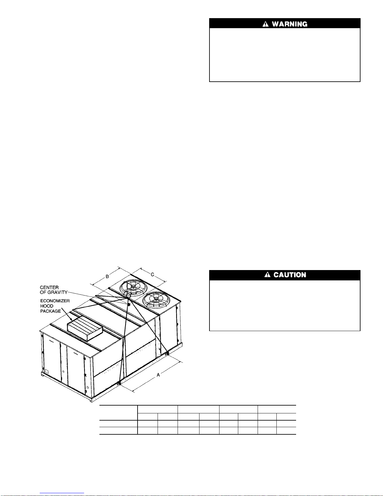
NOTICE TO RIGGERS:
ALL PANELS MUST BE IN PLACE
WHEN RIGGING.
NOTE: Rig with four cables and spread with two
92 in. (2337 mm) spreader bars. Maintain a distance of 74 in. (1880 mm) from top of unit to
eyehook.
NOTE:
Add 32 lb (14.5 kg) for domestic crating.
Add 250 lb (113 kg) for power exhaust.
Add 220 lb (100 kg) for copper condenser coil.
UNIT
50EJQ,EWQ
WEIGHT A B C
lb kg in. mm in. mm in. mm
024 4168 1891 87.68 2227 67.3 1711 43.6 1107
028 4168 1891 87.68 2227 67.3 1711 43.6 1107
Fig. 4 — Rigging Label
5
Page 6
Table 1 — Physical Data
UNIT 50EJQ,EWQ 024 028
NOMINAL CAPACITY (tons) 20 25
OPERATING WEIGHT (lb)*
Unit
Al/Al† 4168 4168
Al/Cu† 4388 4388
Roof Curb (14-in. curb) 365 365
COMPRESSOR
Type Ckt 1 06D824 06D328
Ckt 2 06D824 06D328
Number of Refrigerant Circuits 22
Oil (oz) (Ckt1, Ckt 2) 115 ea. 115 ea.
REFRIGERANT TYPE R-22
Operating Charge (lb-oz)
Circuit 1** 32-2 33-3
Circuit 2 34-6 35-11
OUTDOOR COIL Cross-Hatched
3
⁄89 Copper Tubes, Aluminum Lanced, Aluminum Precoated, or Copper Fins
Quantity 11
Rows...Fins/in. 4...15 4...15
Total Face Area (sq ft) 33.3 33.3
OUTDOOR FAN Propeller Type
Nominal Cfm 13,420 13,420
Quantity...Diameter (in.) 2...30 2...30
Motor Hp (1075 Rpm) 11
INDOOR COIL Cross-Hatched
3
⁄89 Copper Tubes, Aluminum or Copper Plate Fins, Face Split
Rows...Fins/in. 4...15 4...15
Total Face Area (sq ft) 31.7 31.7
Expansion Device Acutrol™ Device
INDOOR FAN Centrifugal Type
Quantity...Size (in.) 2...20x15 2...20x15
Type Drive Belt Belt
Nominal Cfm 8,000 10,000
Motor Hp 5 10†† 15 7.5 10†† 15
Motor Frame Size (Standard) S184T S215T D254T S213T S215T D254T
(High Efficiency) S184T S215T S254T S213T S215T S254T
Motor Bearing Type Ball Ball
Maximum Allowable Rpm 1200 1200
Motor Pulley Pitch Diameter 4.8 4.4 5.7 5.4 6.1 5.5
Nominal Motor Shaft Diameter (in.) 1
1
⁄
8
13⁄
8
15⁄
8
13⁄
8
13⁄
8
15⁄
8
Fan Pulley Pitch Diameter (in.) 12.4 8.6 9.1 12.4 11.1 8.7
Nominal Fan Shaft Diameter (in.) 115⁄
16
115⁄
16
Belt, Quantity...Type 1...BX59 2...BX51 2...5VX530 1...BX59 1...5VX590 2...5VX530
Belt, Length (in.) 62 54 53 62 59 53
Pulley Center Line Distance (in.) 16.0-18.7 15.6-18.4 15.0-17.9 15.6-18.4 15.6-18.4 15.0-17.9
Factory Speed Setting (rpm) 717 924 1096 773 962 1106
HIGH-PRESSURE SWITCH (psig)
Cutout 426 426
Reset (Auto.) 320 320
LOW-PRESSURE SWITCH (psig)
Cutout 77
Reset (Auto.) 22 22
RETURN-AIR FILTERS
Quantity...Size (in.) 10...20x24x2 10...20x24x2
OUTDOOR-AIR FILTERS
Quantity...Size (in.) 8...16x25 8...16x25
4...20x25 4...20x25
Fan, Diameter...Width (in.) 11...10
POWER EXHAUST Direct Drive, 3-Speed, Single-Phase Motor (Factory-Wired For High Speed) and Forward Curved Fan
Motor, Quantity...Hp 4...1
Fan, Diameter...Width (in.) 11...10
LEGEND
Al — Aluminum
Cu — Copper
*Weight of unit does not include barometric relief or power exhaust.
†Indoor coil fin material/outdoor coil fin material.
**Circuit 1 uses the upper portion of outdoor coil, Circuit 2 uses the
lower portion. Circuit 1 uses the lower portion of the indoor coil, Circuit 2 uses the upper portion.
††Motor and drive shown will deliver approximately 2.5 in. wg net
external static. For more drive information, see Table 2.
NOTE: See Table 2 for evaporator fan motor data.
6
Page 7
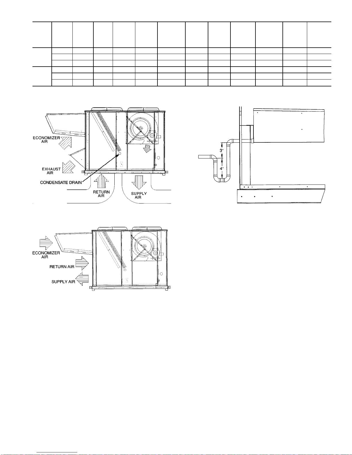
Table 2 — Evaporator Fan Motor Data (Units with Starting Serial Numbers 4197 and Later)
UNIT
SIZE
50EJQ,
EWQ
MOTOR
HP
MOTOR
SHAFT
DIAM.
(in.)
FAN
SHAFT
SPEED
(rpm)
MOTOR
SHEAVE
MOTOR
SHEAVE
PITCH
DIAM.
(in.)
MOTOR
BUSHING
DIAM.
(in.)
FAN
SHEAVE
FAN
SHEAVE
PITCH
DIAM.
(in.)
FAN
BUSHING
DIAM.
(in.)
BELT
(Qty)
OUTSIDE
BELT
LENGTH
(in.)
BELT
TENSION
(lb @
.24 in.)
024
5 1.12 717 BK55 4.8 None-1.125 1B5V124 12.4 B-1.9375 BX59 62 5.10
10 1.38 924 2BK50 4.4 None-1.375 2B5V86 8.6 B-1.9375 (2) BX51 54 5.21
15 1.62 1096 2B5V56 5.7 B-1.625 2B5V90 9.1 B-1.9375 (2) 5VX530 53 6.00
028
7.5 1.38 773 BK60H 5.4 H-1.375 1B5V124 12.4 B-1.9375 BX59 62 6.48
10 1.38 962 1B5V60 6.1 H-1.375 1B5V110 11.1 B-1.9375 5VX590 59 7.37
15 1.62 1106 2B5V54 5.5 B-1.625 2B5V86 8.7 B-1.9375 (2) 5VX530 53 6.12
NOTE: Motor shaft speed is 1750 rpm. The fan shaft diameter is 1
15
⁄16inches.
Step5—TrapCondensate Drain — See Fig. 2, 3,
and 7 for drain location. Condensate drain is open to the atmosphere and must be trapped. Install a trapped drain at the
drain location. One 1-in. FPT coupling is provided inside
unit indoor section for condensate drain connection. A trap
at least 4-in. deep must be used. Trap must be installed to
prevent freeze-up.
Condensate pans are sloped so that water will completely
drain from the condensate pan to comply with indoor air quality guidelines.
Step 6 — Controls Options — The control options
that the units can provide are based on the following parameters: CV (constant volume) operation; stand-alone unit with
field-supplied sensors installed; as a system via the Carrier
Comfort System (TEMP); optional electronic expansion board
installed, linked to the Carrier Comfort Network; and availability of a computer and software (ComfortWorks™,Building Supervisor, and Service Tool) or accessory LID-2B to
access the base control board. See Table 3.
NOTE: Access to the base control board allows unit occupancy schedules, unit timeclock, and various set points to be
changed from their factory-defined default settings.
The units, as shipped, are operable as stand-alone units,
using either a standard (mechanical or electronic) 2-stage heat,
2-stage cool thermostat, or with an electronic room sensor
and a timeclock to establish unit start and stop times.
With a standard thermostat (programmable is optional),
heating and cooling operation is set by space temperature.
With a space sensor and timeclock, the unit will operate
at default values unless they are changed using appropriate
input devices. The space sensor senses space temperature and
may be equipped with a timed override feature, which
allows unit operation during unoccupied periods.
The space sensors may be used in multiples of 4 or 9 to
achieve space temperature averaging. The use of a space sensor also allows the unit to be turned on and off from a
remote signal.
FEATURES WITH THERMOSTAT CONTROL OF UNIT
• two-stage heating (if installed)
• two-stage cooling
• control of unit using Y1, Y2, W1, W2, and G thermostat
inputs
• control of the indoor fan
• outdoor-airtemperature/supply-air temperature monitoring
• control of outdoor fan based on outdoor-air temperature
• control of modulating economizer damper to provide free
cooling when outdoor conditions are suitable, using
supply-air temperature as a control point
Fig. 5 — Air Distribution — Thru-the-Bottom
Fig. 6 — Air Distribution — Thru-the-Side
Fig. 7 — Condensate Drain Connections
(Typical Roof Curb or Slab Mount Shown)
7
Page 8
• control of the economizer damper and indoor fan to obtain
unoccupied free cooling
• provide power exhaust output to an external power exhaust controller
• support a field test for field checkout
• control of 2 stages of power exhaust
• compressor Time Guardt device (power up and minimum
off and on times)
• compressor lockout during low supply-air temperature
Additional features are provided by accessing the standard unit control board via software with a computer. These
features are:
• electronic expansion board features (if installed)
• control board diagnostics
• ability to change supply air set point (economizer control)
• ability to change high outdoor-air temperature lockout set
point (economizer control)
• ability to change power exhaust set points
NOTE: A unit without a thermostat requires a field-supplied
sensor for operation.
FEATURES WITH SENSOR CONTROL OF UNIT (Stand-
Alone Applications) — Unit control is limited to unoccupied default set points, 90 F for cooling, 55 F for heating.
There are 2 sensor options available:
• T-55 sensor will monitor room temperature and provide
unoccupied override capability (1 hour)
• T-56 sensor will monitor room temperature, provide un-
occupied override capability (1 hour), and provide a temperature offset of ± 5° F.
Standard features are:
• support of remote occupied/unoccupied input to start and
stop the unit
• cooling capacity control of 3 stages using economizer and
2 compressors to maintain space temperature to an occupied or unoccupied set point
• enable heating or cooling during unoccupied periods as
required to maintain space temperature within the unoccupied set points
• adjustment of space temperature set points of ± 5° F when
using a T-56 sensor
Features with sensor control of unit with computer access
are:
• 365-day timeclock with backup (supports minute, hour, day
of week, date, month, and year)
• daylight savings time function
• occupancy control with 8 periods for unit operation
• holiday table containing up to 18 holiday schedules
• temperature compensated start to calculate early start times
before occupancy
• access to the Display, Maintenance, Configuration, Serv-
ice, and Set Point data table through network software
When the unit is equipped with a field-supplied space temperature sensor and a remote contact closure (remote start/
stop) on the base control board, the occupied default set points
will monitor unit operation. The occupied default set points
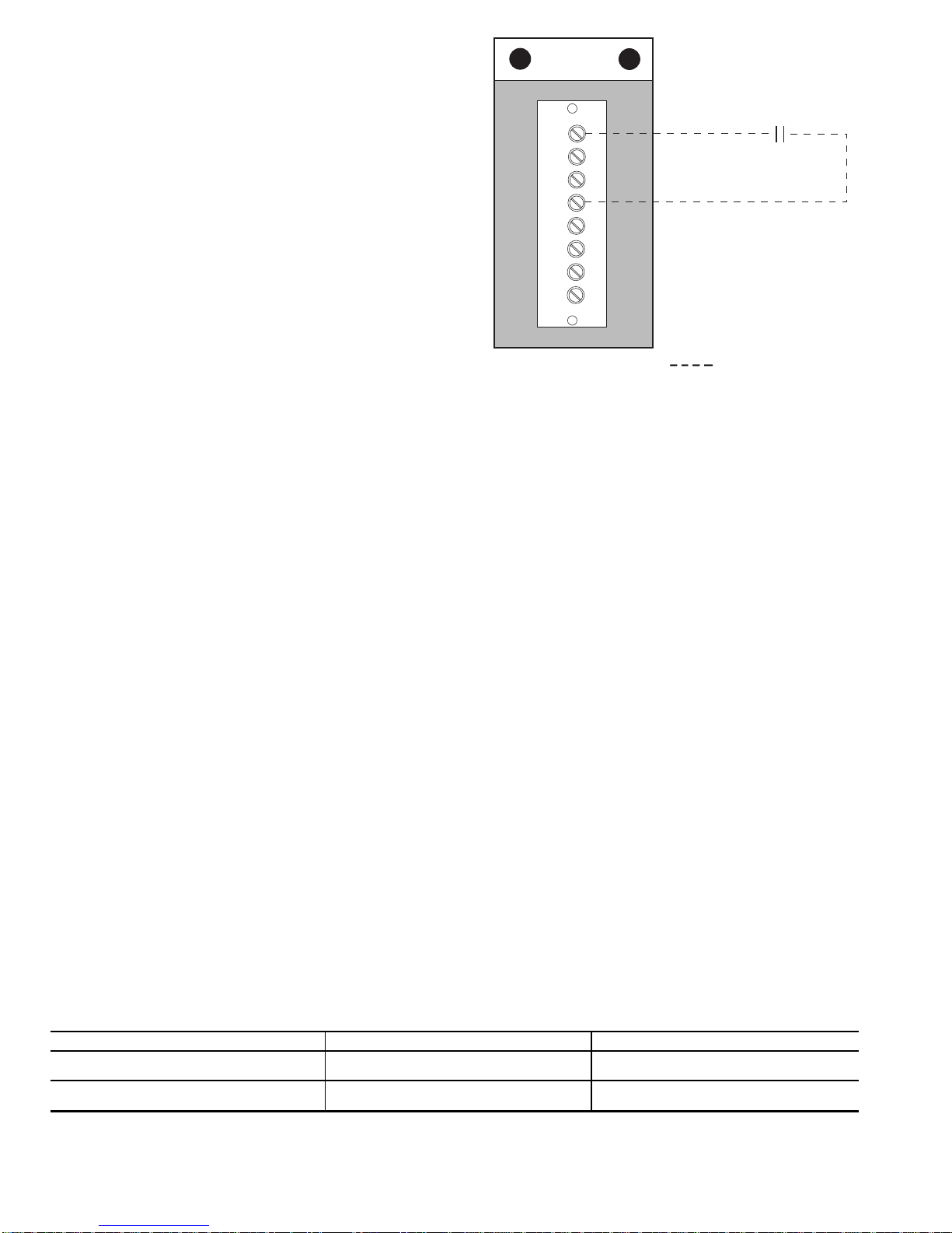
are 78 F cooling and 68 F heating. See Fig. 8 for remote
start/stop wiring.
NOTE: For units (with a field-supplied space temperature
sensor) which have not had the base unit control board
accessed via software to set an occupancy schedule, the
remote start/stop closure will allow the unit to operate in the
pre-configured occupied default set points (based on returnair temperature) of 78 F cooling and 68 F heating. Without
this feature, the unit will control to the unoccupied default
set points of 90 F cooling and 55 F heating.
An electronic expansion board may be field-installed to
provide the following features:
• control of modulating economizer damper to maintain
indoor air quality (IAQ) when outdoor conditions are
suitable
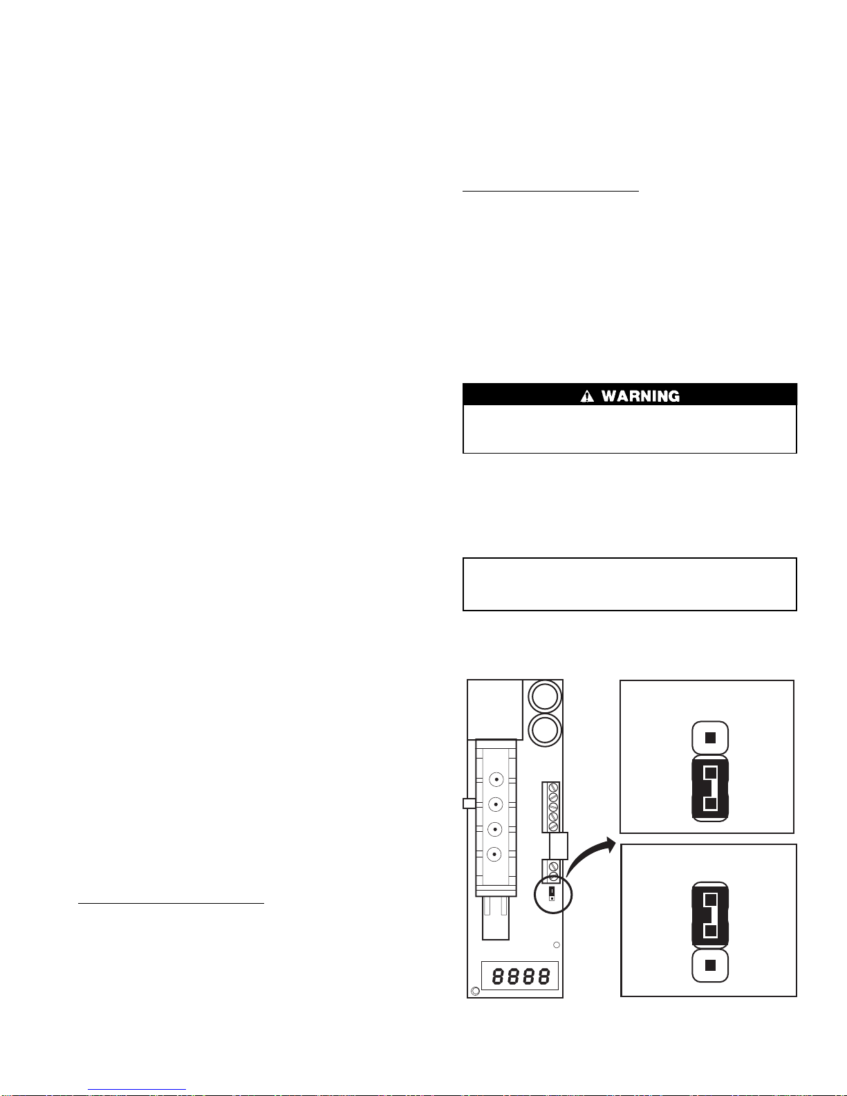
NOTE: The IAQ sensor must be set for current output
(4 to 20 mA) not for voltage output. Ensure the jumper on
the sensor is in the upper position. See Fig. 9.
• provide discrete inputs for fan status, filter status, fieldapplied status, and demand limit
• provide an output for the external alarm light indicator
• provides power exhaust fire outputs for direct control of
modulated power exhaust stages during fire or smoke modes
• smoke control modes including evacuation, smoke purge,
pressurization, and fire shutdown (modulating power exhaust required)
When the unit is connected to the CCN (Carrier Comfort
Network), the following expansion board features can be
utilized.
• perform Demand Limit functions based on CCN loadshed
commands or the state of the discrete input
• alarm monitoring of all key parameters
• CCN protocol
Table 3 — Controls Options and Configurations (Non-Thermostat Applications)
UNIT CONFIGURATION DEFAULT COOLING DEFAULT HEATING
Unit with SPT Sensor
Unoccupied Cooling — 90 F (SPT)
Occupied Cooling — NA
Unoccupied Heating — 55 F (SPT)
Occupied Heating — NA
Unit with SPT Sensor and Remote
Start/Stop Switch
Unoccupied Cooling — 90 F (SPT)
Occupied Cooling — 78 F (SPT)
Unoccupied Heating — 55 F (SPT)
Occupied Heating — 68 F (SPT)
LEGEND
NA — Not Available
SPT — Space Temperature
NOTE: Space temperature sensor and remote stop/switch are fieldsupplied.
R
Y1
Y2
W1
W2
G
C
X
CONTROL
BOX
REMOTE
START/STOP
SWITCH
(FIELD-SUPPLIED)
Fig. 8 — Field Control Remote Start/Stop
LEGEND
Field-Supplied Wiring
8
Page 9
FEATURES WITH SENSOR CONTROL OF UNIT (Network Applications) — The base control board provides, as
standard, a connection for integration into a Carrier Comfort
Network.
When the unit is accessed via a PC equipped with
ComfortWorks™, Building Supervisor, or Service Tool software or accessory LID-2B, the following features can be
accessed:
• on-board timeclock can be programmed
• occupancy schedules can be programmed
• unit set points can be changed
• alarms can be monitored
This access is available on the base control board via a
RJ-11 phone jack or a 3-wire connection to the communication bus. See Fig. 10. The timeclock has a 10-hour minimum
back-up time to provide for unit power off for servicing unit
or during unexpected power outages. For complete Carrier
Comfort System (CCS) or Carrier Comfort Network (CCN)
features and benefits, refer to the product literature.
Step 7 — Make Electrical Connections
POWER WIRING — Units are factory wired for the voltage
shown on the unit nameplate. The main terminal block is
suitable for use with aluminum or copper wires and is sized
for single-point electric heat.
When installing units, provide a disconnect per NEC
(National Electrical Code) of adequate size (MOCP [maximum overcurrent protection] of unit is on the informative
plate). All field wiring must comply with NEC and all local
codes. Size wire based on MCA (minimum circuit amps) on
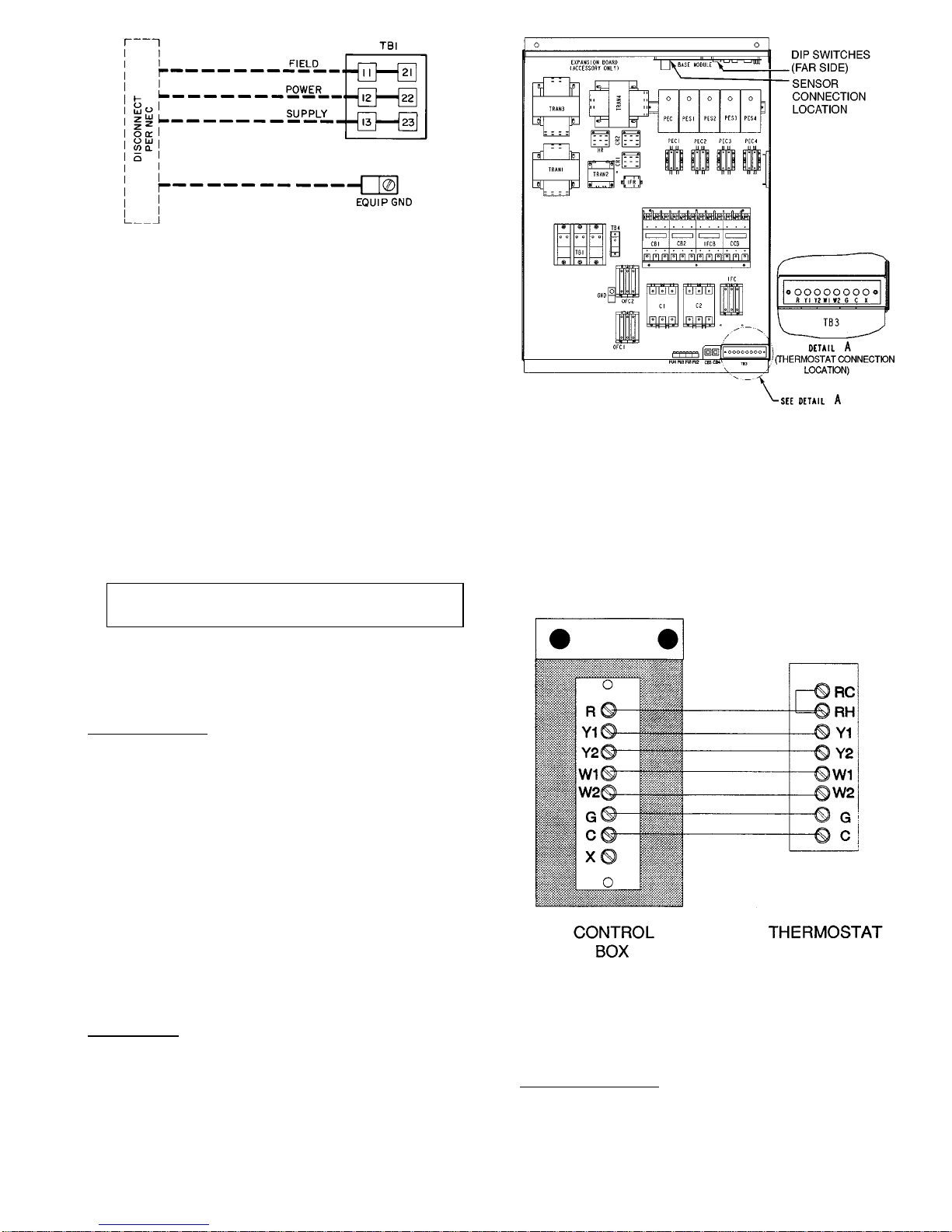
the unit informative plate. See Fig. 11 for power wiring connections to theunit power terminal block and equipment ground.
The main power terminal block is suitable for use with
aluminum or copper wire. See Fig. 11. Units have circuit
breakers for compressors, fan motors, and control circuit. If
required by local codes, provide an additional disconnect,
per NEC and local codes requirements, of adequate size
(Table 4). Whenever external electrical sources are used, unit
must be electrically grounded in accordance with local codes,
or in absence of local codes, with NEC, ANSI (American
National Standards Institute) C1-latest year.
All field wiring must comply with NEC and local code
requirements.
FIELD POWER SUPPLY — Unit is factory wired for voltage shown on nameplate. See Table 4 for electrical data.
Field wiring can be brought into the unit from bottom
(through basepan and roof curb) or through side of unit (corner post next to control box).
A3
1
⁄2-in. NPT coupling for field power wiring and a
3
⁄4-in. NPT coupling for 24-v control wiring are provided in
basepan. In the side post, there are two 21⁄2-in. knockouts for
the field power wiring. See Fig. 2 and 3. If control wiring is
to be brought in through the side of unit, a7⁄8-in. diameter
hole is provided in the condenser side post next to the control box.
If disconnect box is mounted to corner post, be careful
not to drill any screws into the condenser coil.
Routing Through Bottom of Unit — If wiring is brought in
through bottom of unit, use field-supplied watertight conduit
to run power wiring from basepan out through bottom
31⁄2-in. hole to the disconnect box and back into unit to the
main control box.
Use strain relief going into control box through 2
1
⁄2-in.
diameter hole provided. After wires are in unit control box,
connect to power terminal block (see Power Wiring section
on this page).
Low-voltage wiring must be run in watertight conduit from
the basepan to control box and through
7
⁄8-in. diameter hole
provided in bottom of unit control box. Field-supplied strain
relief must be used going into the box. After wiring is in
control box, make connections to proper terminals on terminal blocks (see Field Control Wiring section on page 11).
Install conduit connector in unit basepan or side panel openings provided. Route power and ground lines through connector to connections in unit control box as shown on unit
wiring diagram and Fig. 11.
Routing Through Side of Unit — Route power wiring in
field-supplied watertight conduit into unit through 21⁄2-in. hole.
Strain relief (field supplied) must be used in hole.
Use field-supplied strain relief going into control box through
2
1
⁄2-in. diameter hole provided. After wires are in unit control box, connect to power terminal block (see Power Wiring
section on this page).
Bring low-voltage control wiring through factory-drilled
7
⁄8-in. diameter hole in condenser side post. Use strain relief
going into7⁄8-in. diameter hole in bottom of unit control box.
After wiring is in control box, make connection to proper
terminals on terminal blocks (see Field Control Wiring section on page 11). See Fig. 11.
The unit must be electrically grounded in accordance
with local codes and NEC ANSI/NFPA 70 (National Fire
Protection Association).
Operating voltage to compressor must be within voltage
range indicated on unit nameplate. On 3-phase units, voltages between phases must be balanced within 2% and the
current must be balanced within 10%.
Use the formula in the notes in Table 4 to determine the
percentage of voltage imbalance.
IMPORTANT: If the supply voltage phase imbalance
is more than 2%, contact your local electric utility company immediately.
Unit failure as a result of operation on improper line voltage or excessive phase imbalance constitutes abuse and may
cause damage to electrical components.
JUMPER CONNECTION
FOR VOLTAGE OUTPUT
JUMPER CONNECTION
FOR CURRENT OUTPUT
Fig. 9 — Indoor Air Quality Sensor Configuration
9
Page 10
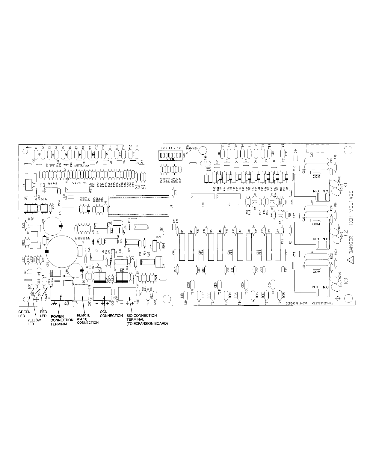
LEGEND
CCN — Carrier Comfort Network N.O. — Normally Open
COM — Common R—Relay
D—Diode SIO — Serial Input/Output
DIP — Dual In-Line Package SW — Switch
LED — Light-Emitting Diode T—Terminal
N.C. — Normally Closed
Fig. 10 — Control Board Diagram
10
Page 11
On 208/230-v units, transformer no. 1 is wired for 230-v.
If 208/230-v unit is to be run with 208-v power supply, the
transformer must be rewired as follows:
1. Remove cap from red (208-v) wire.
2. Remove cap from spliced orange (230-v) wire. Discon-
nect orange wire from black unit power wire.
3. Cap orange wire.
4. Splice red wire and black unit power wire. Cap wires.
IMPORTANT: Be certain unused wires are capped.
Failure to do so may damage the transformers.
FIELD CONTROL WIRING — Install either a Carrierapproved accessory thermostat or a CCN (Carrier Comfort
Network) compatible temperature sensor.A control box diagram is shown in Fig. 12.
Thermostat Wiring — Install a Carrier-approved accessory
thermostat assembly (per current price pages) according to
the installation instructions included with the accessory or
these instructions. Locate thermostat assembly on a solid wall
in the conditioned space to sense average temperature.
Route thermostat cable or equivalent single leads of
colored wire from subbase terminals to low-voltage connections as shown on unit label wiring diagram and in Fig. 13.
NOTE: For wire runs up to 50 ft, use no. 18 AWG (American Wire Gage) insulated wire (35 C minimum). For 50 to
75 ft, use no. 16 AWG insulated wire (35 C minimum). For
over 75 ft, use no. 14 AWG insulated wire (35 C minimum).
All wire larger than no. 18 AWG cannot be directly connected to the thermostat and will require a junction box and
splice at the thermostat.
Set heat anticipators settings to 0.1 for all voltages. Settings may be changed slightly to provide a greater degree of
comfort for a particular installation.
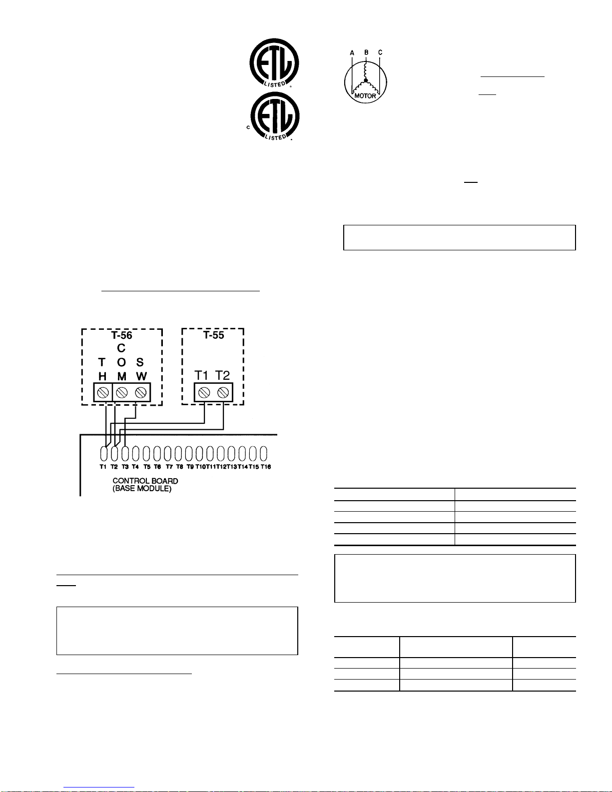
Sensor Wiring — The temperature sensor is wired into the
unit control board. See Fig. 14.
The unit is controlled with a T-55 or T-56 zone sensor.
Terminal T1 (T-55) or TH (T-56) on the sensor is connected
to T1 of the base module board. Terminal T2 (T-55) or COM
(T-56) on the sensor is connected to T2 on the base module
board. If a T-56 set point override sensor is used, the override connection SW on the sensor is connected to T3 on the
base module board.
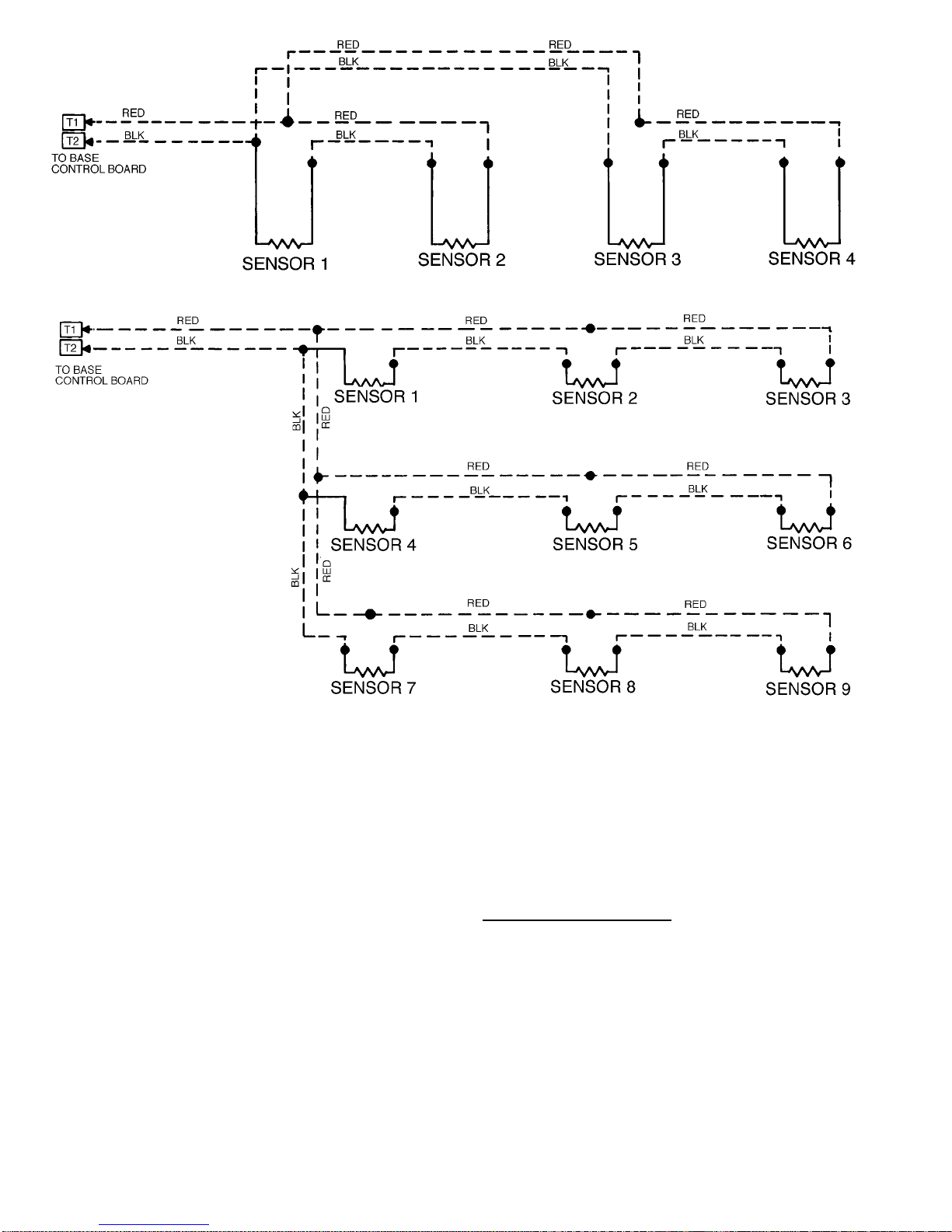
If more than one sensor is being used and averaged, sen-
sors must be wired in multiples of 4 or 9. See Fig. 15.
Remote Field Control — A switch closure across terminals
R and W1 on TB-3 will initiate the Occupied mode. This
can be done manually as well as through a field-supplied
timeclock.
LEGEND
EQUIP — Equipment
GND — Ground
MCM — Thousand Circular Mils
NEC — National Electrical Code
TB — Terminal Block
NOTE: Maximum wire size for TB1 is 500 MCM.
Fig. 11 — Field Power Wiring Connections
LEGEND
CB — Circuit Breaker
DIP — Dual In-Line Package
FU — Fuse
GND — Ground
IFC — Indoor Fan Contactor
OFC — Outdoor Fan Contactor
PEC — Power Exhaust Controller
PES — Power Exhaust Sequencer
TB — Terminal Block
TRAN — Transformer
Fig. 12 — Control Box Diagram
Fig. 13 — Field Control Thermostat Wiring
11
Page 12
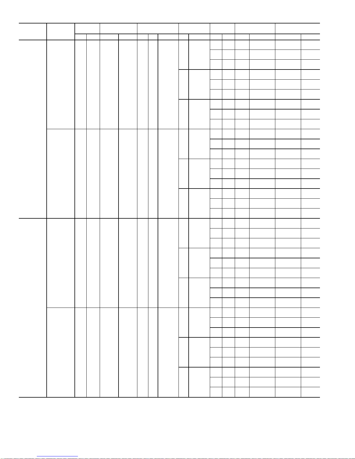
Table 4 — Electrical Data — 50EJQ,EWQ024,028
UNIT
SIZE
50EJQ,EWQ
NOMINAL
VOLTAGE
(3 Ph 60 Hz)
VOLTAGE
RANGE
COMPRESSORS OFM IFM
POWER
EXHAUST
ELECTRIC
HEAT*
POWER SUPPLY
MIN MAX RLA LRA Qty Hp FLA (ea) Hp FLA FLA LRA kW FLA MCA MOCP†
024
208/230 187 254 35.6 198 2 1 5.3
5 16.7/15.2
—
23.6—41.6
—/—
—/—
—/—
—/—
107.4/105.9
131.0/129.5
125/125
150/150
—
23.6—41.6
27/36
27/36
75.1/86.6
75.1/86.6
201.2/214.2
224.8/237.8
225/225
225/250
—
23.6—41.6
54/72
54/72
150.1/173.2
150.1/173.2
257.5/279.1
281.1/302.7
275/300
300/350
10 30.8/28
—
23.6—41.6
—/—
—/—
—/—
—/—
121.5/118.7
145.1/142.3
150/150
175/175
—
23.6—41.6
27/36
27/36
75.1/86.6
75.1/86.6
215.3/227.0
230.7/250.6
225/250
250/275
—
23.6—41.6
54/72
54/72
150.1/173.2
150.1/173.2
271.6/291.9
295.2/315.5
300/300
300/350
15 46.2/42
—
23.6—41.6
—/—
—/—
—/—
—/—
136.9/132.7
160.5/156.3
150/150
175/175
—
23.6—41.6
27/36
27/36
75.1/86.6
75.1/86.6
230.7/241.0
254.3/264.6
250/250
275/275
—
23.6—41.6
54/72
54/72
150.1/173.2
150.1/173.2
287.0/305.9
310.6/329.5
300/350
350/350
460 414 508 17.8 99 2 1 2.7
5 7.6
—
12.6—23.6——
—
—
53.1
65.7
70
80
—
12.6—23.63636
43.3
43.3
107.2
119.8
110
125
—
12.6—23.67272
86.6
86.6
139.7
152.3
150
175
10 14
—
12.6—23.6——
—
—
59.5
72.1
70
80
—
12.6—23.63636
43.3
43.3
113.6
126.2
125
150
—
12.6—23.67272
86.6
86.6
146.1
158.7
150
175
15 21
—
12.6—23.6——
—
—
66.5
79.1
80
90
—
12.6—23.63636
43.3
43.3
120.6
133.2
125
150
—
12.6—23.67272
86.6
86.6
153.1
165.7
175
175
028
208/230 187 254 39.7 228 2 1 5.3
7.5 24.2/22
—
23.6—41.6
—/—
—/—
—/—
—/—
124.1/121.9
147.7/145.5
150/150
175/175
—
23.6—41.6
27/36
27/36
75.1/86.6
75.1/86.6
217.9/230.2
241.5/253.8
225/250
250/275
—
23.6—41.6
54/72
54/72
150.1/173.2
150.1/173.2
274.2/295.1
297.8/318.7
300/300
300/350
10 30.8/28
—
23.6—41.6
—/—
—/—
—/—
—/—
130.7/127.9
154.3/151.5
150/150
175/175
—
23.6—41.6
27/36
27/36
75.1/86.6
75.1/86.6
224.5/236.2
239.9/259.8
225/250
250/275
—
23.6—41.6
54/72
54/72
150.1/173.2
150.1/173.2
280.8/301.1
304.4/324.7
300/350
350/350
15 46.2/42
—
23.6—41.6
—/—
—/—
—/—
—/—
146.1/141.9
169.7/165.5
175/175
200/200
—
23.6—41.6
27/36
27/36
75.1/86.6
75.1/86.6
239.9/250.2
263.5/273.8
250/275
275/275
—
23.6—41.6
54/72
54/72
150.1/173.2
150.1/173.2
296.2/315.1
319.8/338.7
300/350
350/350
460 414 508 19.9 114 2 1 2.7
7.5 11
—
12.6—23.6——
—
—
61.2
73.8
80
90
—
12.6—23.63636
43.3
43.3
115.3
127.9
125
150
—
12.6—23.67272
86.6
86.6
147.8
160.4
150
175
10 14
—
12.6—23.6——
—
—
64.2
76.8
80
90
—
12.6—23.63636
43.3
43.3
118.3
130.9
125
150
—
12.6—23.67272
86.6
86.6
150.8
163.4
175
175
15 21
—
12.6—23.6——
—
—
71.2
83.8
90
100
—
12.6—23.63636
43.3
43.3
125.3
137.9
150
150
—
12.6—23.67272
86.6
86.6
157.8
170.4
175
175
See Legend on next page.
12
Page 13
LEGEND AND NOTES FOR TABLE 4
LEGEND
FLA — Full Load Amps
HACR — Heating, Air Conditioning and
Refrigeration
IFM — Indoor Fan Motor
LRA — Locked Rotor Amps
MCA — Minimum Circuit Amps
MOCP — Maximum Overcurrent Protection
NEC — National Electrical Code
OFM — Outdoor Fan Motor
RLA — Rated Load Amps
*Heater capacity (kW) is based on heater voltage of 208 v,240 v,and
480 v. If power distribution voltage to unit varies from rated heater
voltage, heater kW will vary accordingly. Electric heaters rated at
54 and 72 kW are not available for 208/230 v, 50EWQ units.
†Fuse or HACR circuit breaker.
Bold indicates not available on 50EWQ units.
NOTES:
1. In compliance with NEC requirements for multimotor and combi-
nation load equipment (refer to NEC Articles 430 and 440), the
overcurrent protective device for the unit shall be fuse or HACR
breaker. The Canadian units may be fuse or circuit breaker.
2. Unbalanced 3-Phase Supply Voltage
Never operate a motor where a phase imbalance in supply voltage
is greater than 2%.
Use the following formula to determine the per-
cent of voltage imbalance.
% Voltage Imbalance
max voltage deviation from average voltage
= 100 x
average voltage
EXAMPLE: Supply voltage is 460-3-60.
AB = 452 v
BC = 464 v
AC = 455 v
452 + 464 + 455
Average Voltage =
3
1371
=
3
= 457
Determine maximum deviation from average voltage.
(AB) 457 − 452 = 5 v
(BC) 464 − 457 = 7 v
(AC) 457 − 455 = 2 v
Maximum deviation is 7 v.
Determine percent of voltage imbalance.
7
% Voltage Imbalance = 100 x
457
= 1.53%
This amount of phase imbalance is satisfactory as it is below the
maximum allowable 2%.
IMPORTANT:Ifthe supply voltage phase imbalance ismore than
2%, contact your local electric utility company immediately.
3. MCA calculation for units with electric heaters over 50 kW =
(1.25 x IFM amps) + (1.00 x heater FLA).
Service Tool,Building Supervisor, and ComfortWorks™Software —Access to the control board can be achieved through
the terminal marked CCN via a 3-wire bus.
IMPORTANT: Default bus address is 0. Default element number is 1. Refer to CCN literature for information on network addressing or changing CCN
communication defaults.
Carrier Comfort Network Interface — The 50EJQ,EWQ units
can be connected to the CCN. The communication bus wiring is supplied and installed in the field. Wiring consists of
shielded, 3-conductor cable with drain wire.
The system elements are connected to the communication
bus in a daisy chain arrangement. The positive pin of each
system element communication connector must be wired to
the positive pins of the system element on either side of it,
the negative pins must be wired to the negative pins, and the
signal pins must be wired to signal ground pins. Wiring connections for CCN should be made at the 3-pin plug (CCN
located at the base board). Consult CCN literature for further information.
Conductors and drain wire must be 20 AWG minimum
stranded, tinned copper. Individual conductors must be
insulated with PVC, PVC/nylon, vinyl, Teflon, or polyethylene.An aluminum/polyester 100% foil shield and an outer
jacket of PVC, PVC/nylon, chrome vinyl, or Teflon with a
minimum operating temperature range of −4 F to 140 F is
required. Table 5 lists cables that meet the requirements.
Table 5 — CCN Connection Approved
Shielded Cables
MANUFACTURER CABLE PART NO.
Alpha 2413 or 5463
American A22503
Belden 8772
Columbia 02525
IMPORTANT: When connecting the CCN communication bus to a system element, use a color coding system for the entire network to simplify installation and
checkout. See Table 6.
Table 6 — Color Code Recommendations
SIGNAL
TYPE
CCN BUS CONDUCTOR
INSULATION COLOR
CCN PLUG
PIN NO.
Positive (+) RED 1
Ground WHITE 2
Negative (−) BLACK 3
NOTE: If a cable with a different color scheme is selected,
a similar color code should be adopted for the entire network.
At each system element, the shields of the communication bus cables must be tied together. If the communication
NOTE: Sensor part numbers are as follows:
T-55 — CEC0121448-01
T-56 — CEC0121503-01
Fig. 14 — Field Control Temperature
Sensor Wiring
13
Page 14
bus is entirely within one building, the resulting continuous
shield must be connected to a ground at one point only.If
the communication bus cable exits from one building and
enters another, the shields must be connected to grounds at
the lightning suppressor in each building where the cable
enters or exits the building (one point per building only).
To connect the unit to the network:
1. Turn off power to the control box.
2. Cut the CCN wire and strip the ends of the red (+), white
(ground), and black (−) conductors. (If a different
network color scheme is used, substitute appropriate colors.)
3. Remove the 3-pin male plug from the base module in the
main control box, and connect the wires as follows:
a. Insert and secure the red (+) wire to terminal 1 of the
3-pin plug.
b. Insert and secure the white (ground) wire to ter-
minal 2 of the 3-pin plug.
c. Insert and secure the black (−) wire to terminal 3 of
the 3-pin plug.
4. Insert the plug into the existing 3-pin mating connector
on the base module in the main control box.
Step 8 — Make Outdoor-Air Inlet Adjustments
ECONOMIZER
NOTE: If accessory power exhaust or barometric relief pack-
ages are being added to the unit, install power exhaust or
barometric relief before installing economizer hoods.
Economizer Hood Assembly — The economizer hood is
shipped in a package secured to the outside of the unit and
must be field-assembled. There are 2 hoods on every unit.
The 50EWQ units are side supply and side return. The
return duct limits access to economizer filters from below.
Filter tracks (mounting angle without tabs) must be installed
correctly to allow access to economizer filters from each side.
Perform the following procedure to assemble the economizer hood.
NOTE: Before assembly of the economizer hood, check along
the outer edges of the economizer assembly for any seal strip
protruding past the flanges. Trim the excess seal strip so that
it is flush with the economizer assembly flanges.
SPACE TEMPERATURE AVERAGING — 4 SENSOR APPLICATION
SPACE TEMPERATURE AVERAGING — 9 SENSOR APPLICATION
Fig. 15 — Space Temperature Averaging Wiring
14
Page 15
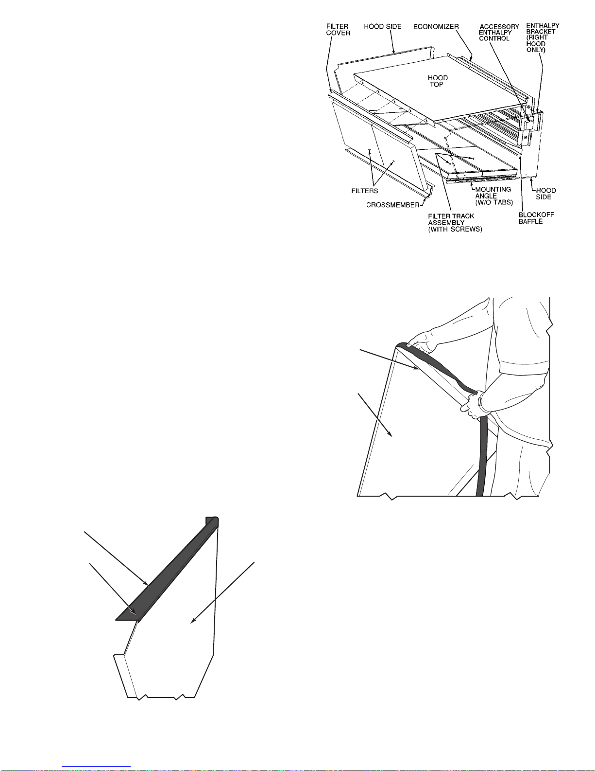
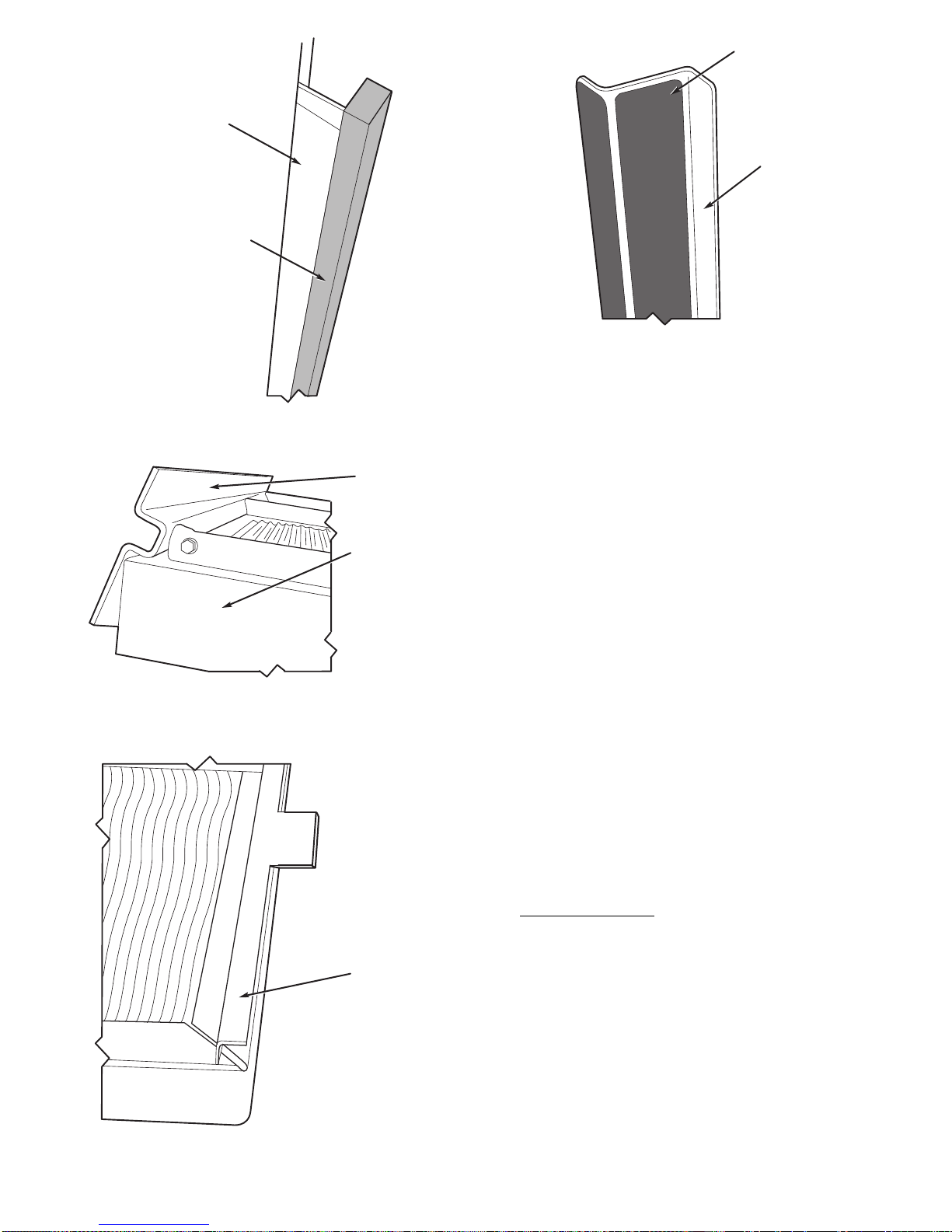
1. Apply black seal strip (provided in package) to outside
top-edge of hood sides.Wrap seal strip over edge to cover
top flange (4 hood sides). Make sure seal strip covers
screw holes. Allow strip to overhang1⁄8-in. past the end
opposite the mounting flange. See Fig. 16.
2. Assemble hood sides, top, and cross member with gasketed screws provided. See Fig. 17.
3. Attach 10 green speed clips (provided) to hood top.
4. Apply black seal strip (provided) to mounting flanges of
hood sides being sure to cover mounting holes. See
Fig. 18.
NOTE: Each hood assembly has a slotted side that should
be adjacent to the other hood when mounted to the unit.
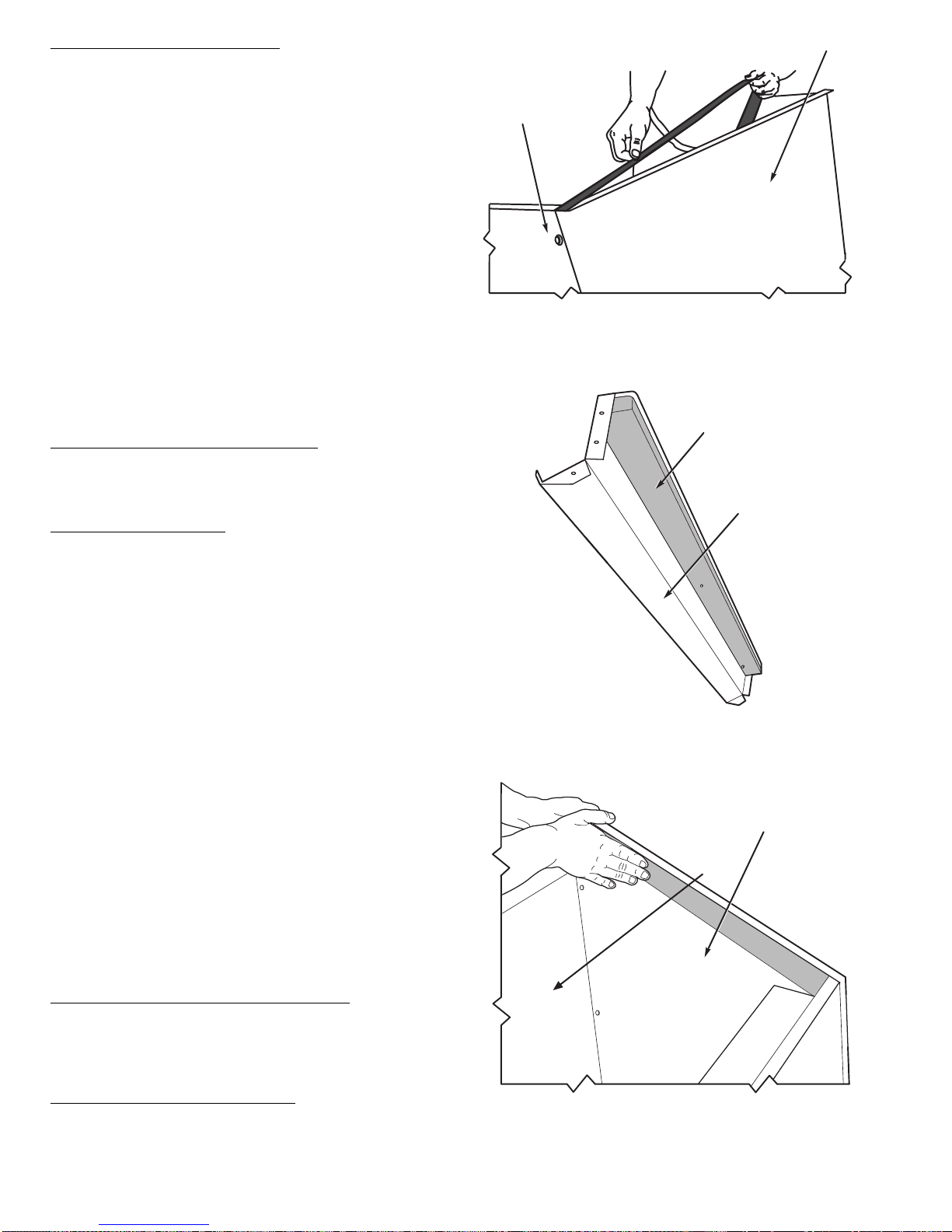
5. Apply black seal strip (provided) to hood top mounting
flange. Seal strip of hood top mounting flange must press
tightly against seal strip of hood side mounting flanges.
See Fig. 19.
6. Add gray foam strip (provided in package) to cross members on bottom tray. See Fig. 20.
7. Place gray foam strip (provided) on inside of slotted hood
side between filter and cross member opposite the mounting end. See Fig. 21.
8. Attach gray foam strip (provided) to block-off baffle on
outer face of flange. See Fig. 22.
9. Remove the screws on each end and along top of damper
assembly of unit. Remove top 2 screws on each side of
filter panel under damper assembly. Set hood assembly
in place and attach to unit using these screws.
10. Attach accessory enthalpy bracket on hood side furthest
from control box end. Locate bracket on inside upper
right-hand corner of economizer hood using hood mounting holes. Mount outdoor-air thermistor to enthalpy bracket
(if purchased). Attach and wire enthalpy assembly. Place
quick connects on enthalpy wires.
11. Remove screws along bottom of damper assembly.
Locate and mount blockoff baffle using these screws.
12. Assemble 2 filter tracks side-by-side with the assembled ends together.
13. Attach mounting angle (without tabs) to the assembled
end of the filter track. See Fig. 23.
14. Attach 6 green speed clips (provided) to mounting angles.
Engagement section of clip faces inside of rack.
15. Attach remaining mounting angle (with tabs) to other
end of the filter track with no. 10 screws provided. See
Fig. 24.
16. Place filter track assembly in bottom of hood by placing
tabbed end into slotted side (with tab on bottom) and
attaching opposite end to hood with speed clips and gasketed screws provided. Tabs can be hand bent after they
have been inserted into the side.
NOTE: The filter track assembly end with screws should
face away from the other hood when mounted on the unit.
NOTE: Tabs from both filter tracks will be in the same
space.After one filter track has been inserted into board,
bend the tabs so they will not interfere with installation
of the second hood.
17. Attach black seal strip (provided) to filter cover. Seal
strip should be applied to the center of the large flange
making sure to cover holes. See Fig. 25.
18. Slide two 20 x 25-in. filters into cross members of hood
assembly.Attach filter cover over filters with screws and
speed clips provided.
HOOD SIDE
TOP
FLANGE
SEAL
STRIP
BLACK
Fig. 16 — Adding Seal Strip to
Top of Hood Sides
NOTE: Left-side economizer hood has mounting angle without tabs
and filter track assembled end on the opposite side.
Fig. 17 — Economizer Hood Assembly
(Right-Side Economizer Hood Shown)
HOOD SIDE
MOUNTING
FLANGE
Fig. 18 — Adding Seal Strip to
Mounting Flange of Hood Sides
15
Page 16
Minimum Damper Position Setting — Setting of the outdoor air damper position is performed in conjunction with a
shortened version of the field-run test. This is performed by
first opening DIP (Dual In-Line Package) switch no. 4 then
no. 6. See Fig. 10 and Direct Digital Controls DIP Switch
Configuration on page 22.
The outdoor-air damper closes. The control allows 90 seconds for the damper to close in case it is in the full open
position. Next, the indoor-fan contactor will energize. The
outdoor-air damper will remain at 0% for 30 seconds. It will
then move to the 10% position for another 30 seconds. This
will be repeated at every 10% increment for 30 seconds until
the damper reaches 100% open. Close DIP switch no. 6 during the 30 seconds immediately after the desired outdoor air
minimum damper position. The 30-second time period is
to allow time where DIP switch no. 4 can be closed. The
default value of the minimum outdoor air damper position is
20%. If the desired minimum position is 30%, allow the damper
position to go to 10% for 30 seconds, then 20% for 30 seconds, and when it reaches 30% close DIP switch no. 4 during the 30-second period following the 30% position. Close
DIP switch no. 6 to complete the test.
The minimum outdoor air damper position is now set.
ECONOMIZER SETTINGS
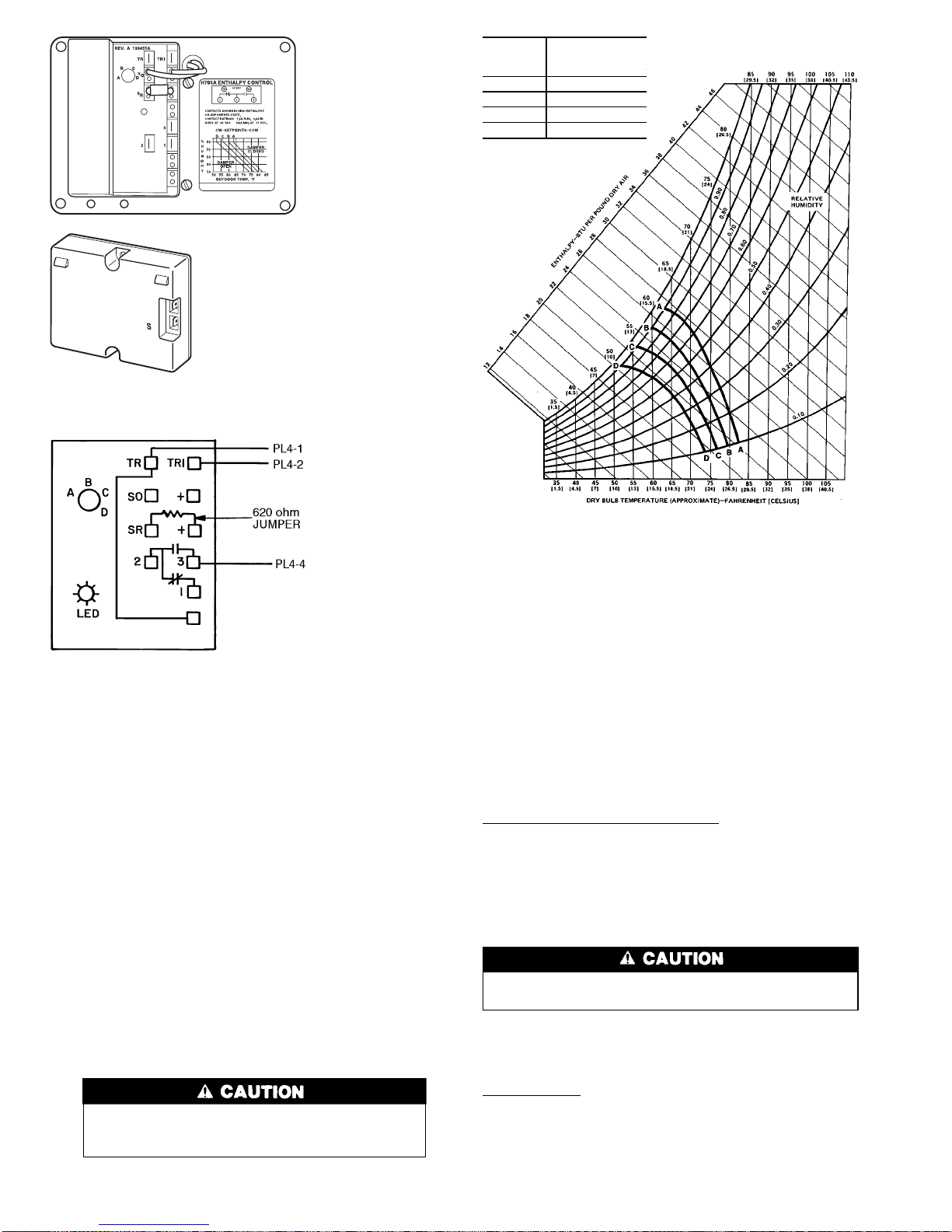
Accessory Enthalpy Control (Fig. 26) — The control
(HH57AC077) is mounted in the economizer hood. See
Fig. 17. The enthalpy setting adjustment is on the enthalpy
control. For maximum benefit of outdoor air, set enthalpy
control to A. See Fig. 27 and 28.
Enthalpy Control Installation — The outdoor air enthalpy control is installed on the inside panel of the outdoor air hood.
The enthalpy control should be mounted when the outdoor
air hoods are assembled. To install the control, perform the
following procedure:
1. Turn off all power. Ensure disconnect is locked out.
2. Remove the economizer inlet filters from the bottom of
the right hand economizer hood. See Fig. 17. See Fig. 29
for economizer details.
3. Mountthe outdoor air enthalpy sensor inside the right econo-
mizer hood on the right side panel of the hood, adjacent
to the outdoor-air thermistor.
4. Locate the red, violet, and brown wires near the outdoor
air thermistor. Remove the splice from the red and violet
wires. Remove the cap from the brown wire.
5. Install a
1
⁄4-in. push on terminal (field-supplied) on the
violet and brown wires.
6. Connect a
1
⁄4-in. push on terminal (field provided) to one
end of a 18-gage, 6-in. jumper wire (field-provided). Connect the other end to the red wire and attach a1⁄4-in. push
on connector (field provided).
7. Connect the red wire with the jumper to terminal TR1.
Connect the jumper to terminal 2. Connect the brown wire
to terminal TR. Connect the violet wire to terminal 3. All
connections are on the enthalpy control.
8. Replace the economizer filters.
9. Return power to unit.
Accessory Differential Enthalpy Control (Fig. 26) — The control (HH57AC077), in conjunction with the accessory enthalpy sensor (HH57AC078), controls economizer operation
according to the differentialenthalpy.The control is mounted
in the economizer hood. The sensor is mounted in the return
duct (50EJQ) or return air plenum (50EWQ).
DifferentialEnthalpy Sensor Installation — To install the control, perform the following procedure:
1. Turn off all power. Ensure disconnect is locked out.
HOOD TO
P
HOOD SIDE
Fig. 19 — Adding Seal Strip to
Hood Top Mounting Flange
CROSS MEMBER
GRAY FOAM STRIP
Fig. 20 — Adding Foam Strip to Cross Member
HOOD SIDE
(SLOTTED)
HOOD
TOP
Fig. 21 — Adding Foam Strip to Hood Side
16
Page 17
2. Remove the economizer inlet filters from the bottom of
the right hand economizer hood. See Fig. 17.
3. Remove the factory-installed, 620-ohm jumper between
terminals SR and + on the enthalpy control located
inside the outdoor air hood.
4. Connect the violet wire from the enthalpy sensor kit to
the + terminal on the enthalpy control. Connect the blue
wire from the enthalpy sensor kit to the SR terminal on
the enthalpy control.
5. Turn the enthalpy control set point potentiometer clockwise past the ‘‘D’’ setting on the enthalpy control to
configure the control to operate on differential enthalpy.
See Fig. 27.
6. Remove the return-air enthalpy sensor from the accessory package. Using the screws provided, mount the
sensor inside the return duct near the unit. Do not locate
the control too far from the unit, or the wires will not
reach from the sensor to the control. On 50EWQ units,
the enthalpy sensor can be installed in the return air section of the unit, under the return air dampers.
7. Route the wires from the enthalpy sensor to the return
air enthalpy control through the holes on the inside of
the hinged filter access panel. The holes are blocked by
plug buttons which should be removed.
8. Use field-supplied wire ties to attach the violet wire to
the + terminal and the blue wire to the SR terminal.
9. Replace economizer filters.
10. Return power to unit.
Disable Economizer — For applications where the econo-
mizer will not be used (areas of high humidity), the economizer should be disabled. Todisable the economizer, perform
the following:
1. Turn of power. Lock out disconnect.
2. Locate the OATin the right hand outdoor air damper area.
3. Locate the splice connecting the violet wire coming from
T24 on the base module board to the red wire coming
from T29 on the base module board. Remove the wire
nut and break the red to violet wire splice.
4. Cap off both wires. When the connection is broken the
base module is fooled into thinking that the enthalpy is
not acceptable and economizer operation is disabled.
BLOCKOFF BAFFLE
GRAY FOAM STRIP
Fig. 22 — Adding Foam Strip to Block-Off Baffle
MOUNTING ANGLE
(WITHOUT TABS)
FILTER TRACK
ASSEMBLY
Fig. 23 — Mounting Angle (Without Tabs)
Attached to Filter Track Assembly
MOUNTING ANGLE
(WITH TABS)
Fig. 24 — Mounting Angle (With Tabs)
Attached to Filter Track Assembly
BLACK SEAL STRIP
(CENTERED)
FILTER COVER
Fig. 25 — Attaching Seal Strip
to Filter Cover
17
Page 18
NOTE: Economizer operation can also be disabled by disconnecting the OAT. This is not recommended due to
the fact that Unoccupied Free Cooling, IAQ Purge, and Low
Ambient Fan Cycle Control are also disabled. An OAT failure alarm will also be issued.
Step 9 — Position Power Exhaust/Barometric
ReliefDamper Hood —
All electrical connections have
been made and adjusted at the factory. The power exhaust
blowers and barometric relief dampers are shipped
assembled and tilted back into the unit for shipping. Brackets and extra screws are shipped in shrink wrap around the
dampers. If ordered, each unit will have 4 power exhaust
blowers and motors or 4 barometric relief dampers.
1. Remove 9 screws holding each damper assembly in
place. See Fig. 30. Each damper assembly is secured with
3 screws on each side and 3 screws along the bottom.
Save screws.
2. Pivoteach damper assembly outward until edges of damper
assembly rest against inside wall of unit.
Be careful when tilting blower assembly. Hoods
and blowers are heavy and can cause injury if
dropped.
3. Secure each damper assembly to unit with 6 screws —
across top (3 screws provided) and bottom (3 screws from
Step 1) of damper.
4. With screws saved from Step 1, install brackets on each
side of damper assembly.
5. Remove tape from damper blades.
Step10 —InstallAccessories — Afterall the factory-
installed options have been adjusted, install all fieldinstalled accessories. Refer to the accessory installation
instructions included with each accessory.
MOTORMASTERt III INSTALLATION
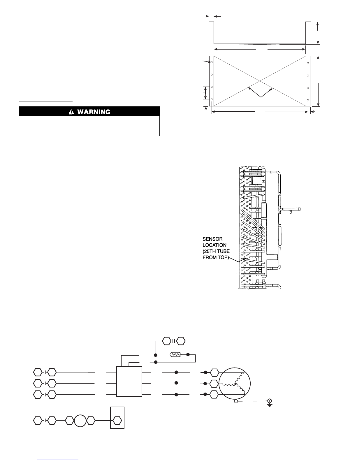
Install Field-Fabricated Wind Baffles — Wind baffles must
be field-fabricated for all units to ensure proper cooling cycle
operation at low-ambient temperatures. See Fig. 31 for baffle
details. Use 20-gage, galvanized sheet metal, or similar
corrosion-resistant metal for baffles.Use field-supplied screws
to attach baffles to unit. Screws should be1⁄4-in. diameter
and5⁄8-in. long. Holes for wind baffles are pre-punched in
the unit sheet metal.
To avoid damage to the refrigerant coils and electrical
components, use recommended screw sizes only.
The wind baff lesattach to flanges formed on the outer sheet
metal of the unit where the condenser coil tube sheets
attach.
Install Controls — Only one Motormaster III control is required per unit.
Motor — The circuit no. 1 (lead compressor) outdoorfan motor (OFM) will need to be changed out in the field to
+
C7400A1004
HH57AC077
ENTHALPY
CONTROL
HH57AC078
ENTHALPY SENSOR
(USED WITH ENTHALPY
CONTROL FOR DIFFERENTIAL
ENTHALPY OPERATION)
Fig. 26 — Differential Enthalpy Control and Sensor
NOTE: Switches shown in high
enthalpy state. Terminals 2 and
3 close on enthalpy decrease.
Fig. 27 — Wire Connections for Solid-State
Enthalpy Control (HH57AC077)
CONTROL
CURVE
CONTROL POINT
(APPROX. DEG.)
AT 50% RH F (C)
A 73 (23)
B 70 (21)
C 67 (19)
D 63 (17)
RH — Relative Humidity
Fig. 28 — Psychrometric Chart for
Enthalpy Control
18
Page 19
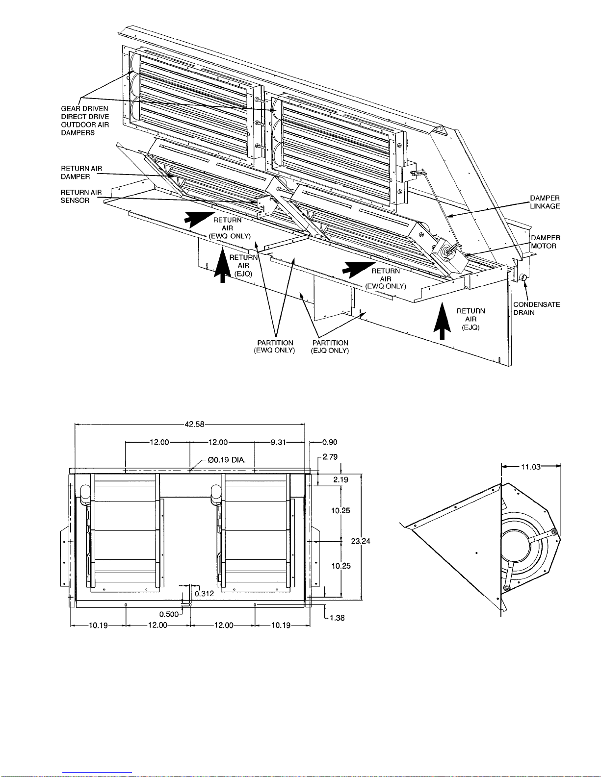
NOTE: Partitions are shown for both side supply
(EWQ) and vertical supply (EJQ).
Fig. 29 — Economizer Details
/o—Diameter
NOTES:
1. Unless otherwise specified, all dimensions are to outside of part.
2. Dimensions are in inches.
3. Two assemblies per unit.
Fig. 30 — Barometric Relief Damper and Power Exhaust Mounting Details
19
Page 20
accommodate the Motormastert III accessory. The replacement motor part no. is HD52AK652. The circuit no. 2 OFM
is controlled to shut off at 65 F outdoor air temperature (during cooling mode only).
Sensor — Install the sensor for thermistor input control in
the location shown in Fig. 32.
Signal Selection Switch — Remove the cover of the Motormaster III control. Set the switch to accept the thermistor
sensor input signal. Set the frequency to match the unit power
supply (60 Hz).
Motormaster III Control — The recommended mounting
location is in the indoor fan section, mounted on the panel
that separates the indoor and outdoor sections.
Electrical Connections
To avoid possibility of electrical shock and personal injury, turn off all power to unit before making electrical
connections.
When replacing the OFM, reconnect the black, yellow, and
blue wires form the outdoor fan contactor to the black, yellow,and blue wires of the Motormaster III control. Run new
wires from the red, orange, and brown wires to the leads of
the new OFM. Connect the green wire from the control to
ground. See Fig. 33.
InstallAccessory Low Ambient Kit — An additional Motormaster relay, HN61KZ024, will be required so that the fan
motor will operate at low ambients during heating. The electrical connections are made to a socket, HY07RB030. After
the electrical connections, the socket is mounted in the control box and the relay is inserted into the socket.
Connect one sensor lead to the violet control signal lead
on the Motormaster III controller and to a field-supplied
16 AWG wire with a wirenut. Connect the remaining sensor
lead to the gray control sensor lead on the Motormaster III
controller and to another field-supplied 16 AWG wire with
a wirenut. Route both field-supplied wires through a hole in
the control box. Attach the wires to screw terminals 5 and 9
on the socket. There is a normally open set of contacts
between terminals 5 and 9.
Connect a field-supplied 16 AWG wire to screw terminal
13 on the socket and to QC terminal 2 on the HR2 relay.
Connect a field-supplied 16 AWG wire to screw terminal 14
on the socket and to QC terminal 2 on TB2. The HR2 terminal 2 has 24-volt power when there is a call for heat; this
will then energize the Motormaster relay.
BLK
YEL
BLU
MMSN
RED
BRN
ORN
OFC1
12
22
13
23
MOTOR
MASTER
III
ACY
GRA
VIO
21
11
9
5
MMR
GRN YEL
OFM1
BLK
1
YEL
2
BLU
3
13
23
MMR
13
14
2
HR2
TB2
LEGEND
HR — Heater Relay
MMR — Motormaster Relay
MMSN — Motormaster Sensor
OFC — Outdoor Fan Contactor
OFM — Outdoor Fan Motor
TB — Terminal Block
NOTE: Motormaster Relay part no.is HN61KZ024 with HY07RB030 socket.
Fig. 33 — Motormaster III Device Wiring, 50EJQ,EWQ024 and 028
18
77.7
1
BOTH SIDES
CROSS-BREAK
78.7
0.5
61
4.62
17.167
BETWEEN
HOLES
(TYPICAL)
0.312 DIA
HOLES
NOTE: All dimensions are in inches.
MATERIAL: 20 gage galvanized steel or other non-corrosive
material.
Fig. 31 — Motormaster III Baffle Details
Fig. 32 — Motormaster III Sensor Location
(Sizes 024,028)
20
Page 21
START-UP
Use the following information and Start-Up Checklist on
page CL-1 to check out unit PRIOR to start-up.
Unit Preparation — Check that unit has been installed
in accordance with these installation instructions and applicable codes.
CompressorMounting — Loosenthe compressor hold-
down bolts until sidewise movement of the washer under
each holddown bolt head can be obtained. Do not loosen
completely as bolts are self-locking and will maintain
adjustment.
Service Valves — Ensure that the suction and dis-
charge service valves are open. Damage to the compressor
could result if they are left closed.
Internal Wiring — Check all electrical connections in
unit control boxes; tighten as required.
Refrigerant Service Ports — Each refrigerant sys-
tem has one suction port located in the top of the compressor
motor casing. All units also have one service port on the liquid line valve and one on the compressor discharge valve.
Be sure that caps on the ports are tight.
Minimum Outdoor Air Temperature — The mini-
mum outdoor air temperature is −20 F ambient for heating
duty.
Power Exhaust— The optional non-modulating power
exhaust is a two-stage design where the operation of the
exhaust fans is linked to economizer position. When the
supply fan is running and the economizer is 25% open, the
base module closes contacts, activating 2 exhaust fans. When
the economizer position reaches 75% open, the base module
activates the other 2 exhaust fans. The fans will turn of fwhen
the economizer closes below the same points. The economizer position set points that trigger the exhaust fans
can be modified, but only through use of the Service Tool,
ComfortWorks™, or Building Supervisor software. If singlestage operation is desired, adjust the economizer set points
to identical values at the desired point to activate all exhaust
fans.
The optional modulating power exhaust is controlled by a
modular electronic sequencer system. This system consists
of a model R353 signal input module and 4 model S353 staging modules. The signal input module receivesa0to10vdc
signal from the building pressure transducer,which is mounted
adjacent to the supply static transducer behind the filter
access panel. The modules are mounted just below the unit
control board. The left module is the R353, and the 4 modules on the right are S353 modules for stages 1 through 4.
On the unit wiring label, the R353 is designated PEC, and
the S353 modules are designated PES1 through PES4.
The building pressure transducer range is − 0.5 to
+ 0.5 in. wg. It is powered bya0to10vdcsignal. A factoryinstalled hose at the ‘‘Lo’’ connection leads to atmosphere,
and a field-supplied hose must be connected to the ‘‘Hi’’ connection and led into the building to a point where building
pressure is to be controlled. There is a plug button in the
bulkhead just above the transducers, for use in leading the
hoses into the building via the return air ductwork.
NOTE: With ‘‘Lo’’ connection to atmosphere and ‘‘Hi’’
connection to building, the unit will attempt to maintain a
positive building pressure. To maintain a negative building pressure, connect ‘‘Lo’’ to building and ‘‘Hi’’ to the
atmosphere.
There are 3 adjustments at the R353 module, all of which
have been factory set. In the center of the circuit board is a
set of 4 pins with a jumper, labeled J2. This determines the
mode of operation. The bottom 2 pins must be jumpered for
direct operation. Direct operation means that the staging modules are activated in sequence as the input signal increases.
At the upper right corner of the board is a set of 5 pins and
jumper, which determines the time constant for the control.
The time constant is the delay in response built into the controls. The jumper should be on the middle or bottom 2 pins,
for the maximum time constant. The delay can be decreased,
if desired, by moving the jumper progressively upward,
always jumpering adjacent pins.
At the lower left corner of the board below the terminal
strip is a resistor marked R27. This must be removed in order to obtain the 0 to 10 vdc signal output. There will not be
a resistor on a factory-supplied module, but a resistor may
be present on a replacement module and must be removed.
The R353 module has a terminal block with 7 connections available for wiring. The 2 right-hand terminals are for
the 24 vac and common connections. The next 2 terminals
are for the 0 to 10 vdc signal. Consult the wiring label for
wire identification if replacing the module. The 3 left-hand
terminals are not used for this application.
The S353 module has an LED (light-emitting diode), a set
of 4 jumper pins, and 2 potentiometers. The LED will light
whenever the module is activated, providing a visual indication of the number of exhaust fans running. The jumper
pins are arranged in a square format. Two jumpers are used
to determine the mode of operation (direct or reverse). The
2 jumpers must be arranged horizontally for direct action
(factory set).
At the top of the module are 2 potentiometers. The left
potentiometer adjusts the offset. The right potentiometer
adjusts differential.The potentiometers are factory set for a
nominal 0 in. wg building pressure.
The offset set point is defined as the point at which a module turns off a fan, and is measured in terms of percent of the
input signal. For control purposes, 0 offset is at an arbitrary
‘‘floor’’ which is established at 10% of the input signal, or
1 vdc. In this example, the first stage will turn off at 30%
(3 vdc), and the offset potentiometer will be set at 20%. The
second stage will turn off at 50% signal (5 vdc), and the offset potentiometer will be set at 40%. The fourth stage is at
the maximum 75% offset, which equates to 85% signal or
8.5 vdc. The offset potentiometer is calibrated in 10%
increments.
Table 7 relates building pressure to signal level.
Table 7 — Potentiometer Signal Levels
BUILDING PRESSURE
(in. wg)
SIGNAL LEVEL
(vdc)
−0.50 2
−0.25 4
0.00 6
0.25 8
0.50 10
If the building pressure is controlled at 0 in. wg, offset of
the first stage should be set at 50%, which equates to 60%
of the input signal, or 6 vdc. The other stages can then be set
as desired between 50% and 75%.
21
Page 22
The default offset set points for modulating power ex-
haust are shown in Table 8.
Table 8 — Power Exhaust Default Set Points
STAGE
OFF-
SET
DIFFER-
ENTIAL
OFF
VOLTAGEONVOLTAGE
OFF
STATIC
PRESSURE
(in. wg)
1 50% 3% 6.0 6.3 0.00
2 55% 3% 6.5 6.8 0.06
3 60% 3% 7.0 7.3 0.12
4 64% 3% 7.4 7.7 0.18
The differential set point is the difference between the
turn off point and the turn on point for each module. It also
is calibrated in terms of percent of input signal, and has a
range of 1% to 7%. The differential potentiometer is calibrated in 1% increments, and is factory set at approximately
3%. It is recommended to leave the set point at 3%, to minimize cycling of the fans.
The offset and differential potentiometers have been
factory set for atmospheric pressure. Do not change these
settings until there is some experience with the building. In
most cases the factory settings will be satisfactory. However, if the building pressure is not being maintained as
desired, then some minor adjusting on a trial and error basis
can be made.
Direct Digital Controls DIP Switch Configuration —
The Direct Digital Control (DDC) board must be
configured for each application. The DDC board is configured through the DIP switches located on the board. There
are 8 DIP switches which configure 8 different applications
of the DDC. See Table 9. DIP switch 1 is on the left of the
block. DIP switch 8 is on the right of the block. To open a
DIPswitch, push the switch toward the side marked ‘‘OPEN’’
on the rocker switch with a suitable tool (small-blade screwdriver). To close a DIP switch, push the switch away from
the side marked 9OPEN9 on the rocker switch. Factory settings are shown in Table 10.
The DIP switch configurations of the unit control soft-
ware are as follows:
• Set DIP switch 1 to closed to configure the unit to operate
as a CV (constant volume) unit
• DIP switch 2 configures the unit to use a space sensor or
a thermostat
• DIP switch 3 configures the DDC for use with an electronic expansion board
• DIP switch 4 is used to field test the unit
• DIP switch 5 is used to specify the type of power exhaust
• DIP switch 6 configures the Time Guardt override and,
when used with the field test function, sets the minimum
damper position
• Set DIP switch 7 to closed to configure the unit indoor fan
for use with electric heat
• Set DIP switch 8 to open to configure the unit for heat
pump operation
Table 9 — DIP Switch Configuration
SETTING 1 2 3 4 5 6 7 8
OPEN —
CCN or Sensors
Used
Expansion
Board
Field Test
ON
Modulated
Power
Exhaust
Time GuardT Override
ON
Gas Heat
Heat Pump
Operation
IN CONJUNCTION
WITH FIELD TEST
— Set Minimum
Damper Position
CLOSED CV Thermostat
Base Control
Board Only
Field Test
OFF
Constant
Volume
Power
Exhaust
Time Guard Override
OFF
Electric Heat
Air Conditioner
Operation
LEGEND
CCN — Carrier Comfort Network
CV — Constant Volume
NOTES:
1. The OPEN side of the DIP switch is marked ‘‘OPEN.’’ When the
rocker switch is on the ‘‘OPEN’’ side of the switch, the switch is
OPEN.
2. DIP switch no. 7 is used for indoor fan control during heat opera-
tion. It should be set to closed.
3. When the unit is field-tested (DIP switch 4 to OPEN), the function
of DIP switch 6 changes and it is used to set the minimum damper
position.
Table 10 — DIP Switch Factory Settings
UNIT 12345678
50EJQ,EWQ Closed Closed Closed Closed Closed Closed Closed Open
22
Page 23
CrankcaseHeater(s) — Heater(s) is energized as long
as there is power to the unit, except when the compressors
are operating.
IMPORTANT: Unit power must be on for 24 hours
prior to start-up. Otherwise, damage to compressor may
result.
Indoor Fan — Fan belt and fixed pulleys are factory-
installed. See Tables 11 and 12 for Fan Performance Data.
See Table 13 for Motor Limitation data. Be sure that fans
rotate in the proper direction. Static pressure drop for power
exhaust, barometric relief damper, and electric heat is negligible. To alter fan performance, see Indoor Fan Performance Adjustment section on page 29.
Outdoor Fans and Motors — Fans and motors
are factory set. Refer to Outdoor-Fan Adjustment section
(page 30) as required.
Return-Air Filters — Check that correct filters are
installed in filter tracks. See Table 1. Do not operate unit
without return-air filters.
Filter Replacement — To replace filters, open filter
access door (marked with label). Remove inner access panel.
Remove plastic filter retainer in between filter tracks by sliding and pulling outward. Remove first filter by sliding it out
of the opening in filter track. Locate filter removal tool, which
is shipped next to the return air dampers. Use the filter
removal tool to remove the remaining filters.
Outdoor-AirInlet Screens — Outdoor-airinlet screens
must be in place before operating unit.
EconomizerAdjustment— Remove filter access panel.
Check that outdoor-air damper is closed and return-air damper
is open.
Economizer operation and adjustment is described in
Sequence of Operation and Make Outdoor Air Inlet Adjustments sections (this page and page 14), respectively.
Sequence of Operation
NOTE: Unit is shipped with default values that can be changed
through Service Tool or CCN software.
COOLING — On power up, the control module will activate the initialization software. The initialization software
reads DIP switch no. 1 position to determine CV operation.
Next, DIP switch no. 2 is read to determine if the control is
thermostat or sensor type operation. The initialization
sequence: clears all alarms and alerts; re-maps the input/
output database for CV operation; sets maximum heat stages
to 2; and sets maximum cool stages to 3. The control module
reads DIP switch no. 3 and determines if the unit will use
expansion mode operation.
The thermostat function performs a thermostat based control by monitoring Y1, Y2, W1, W2 and G inputs. These
functions control stages: cool1, cool2, heat1, heat2, and the
indoor fan respectively. If the TSTAT function is not
selected, the control module determines the occupancy state
based on the system time schedules or with remote occupied/
unoccupied input. If Temperature Compensated Start is
active, the unit will be controlled as in the Occupied mode.
User defined set points are shown in Table 14.
Occupied or unoccupied comfort set points must be
selected. Use of the space temperature offset input can also
be configured. The control module will set appropriate
operating mode and fan control.The control module will turn
on indoor fan if in Occupied mode or if the unit is in Unoccupied mode and the space temperature is outside of the
unoccupied comfort set points (Unoccupied Heat or Unoccupied Cool). The control module will then monitor space
temperature against comfort set points and control heating
or cooling stages as required. If the system is in the Occupied mode, the economizer will operate as required. If the
system is in Unoccupied mode, the system will perform nighttime free cool and IAQ (indoor air quality) pre-occupancy
purge as required (when functions are enabled via software).
Whenever the DX (direct expansion) cooling is requested,
the outdoor fan will operate.
The control module will operate economizer, run diagnostics to monitor alarms/alerts at all times, and respond to
CCN communications to perform any configured network
POC (product outboard control) functions such as time/
outdoor-airtemperature broadcast and global occupancy broadcast. When the optional expansion I/O board is employed, it
will: perform a periodic scan and maintain a database of
expanded I/O points; perform Fire/Smoke control (power
exhaust required); if in Occupied mode, perform IAQ control and monitor the fan, filter, demand limit, and fieldapplied status (with accessories).
If thermostats are used to energize the G input, the control
module will turn on the indoor fan without delay and open
the economizer dampers to minimum position. If thermostats are used to deenergize the G input, the control module
will turn offthe indoor fan without delay and close the economizer dampers.
When cooling, G must be energized before cooling can
operate. The control module determines if outdoor conditions are suitable for economizer cooling using the standard
outdoor air thermistor. For the economizer to function for
outside air cooling: the enthalpy must be below the enthalpy
set point; the outdoor-air temperature must be equal to or
less than the High Outdoor Air Temperature Lockout (default is 65 F); the SAT (supply-air temperature) thermistor
must not be in alarm; and the outdoor air reading is available. When these conditions are satisfied, the control module will use economizer as the first stage of cooling.
WhenY1 input is energized, the economizer will be modulated to maintain SAT at the defined set point. (The default
is 55 F.) When SAT is above the set point, the economizer
will be 100% open. When SAT is below the set point, the
economizer will modulate between minimum and 100% open
position. When Y2 is energized, the control module will turn
on compressor 1 and continue to modulate the economizer
as described above. If the Y2 remains energized and the
SAT reading remains above the set point for 15 minutes, compressor 2 will turn on. If Y2 is deenergized at any time, only
the last stage of compression that was energized will be turned
off.If outdoor conditions are not suitable for economizer cooling, the economizer will go to minimum position and cycle
compressors 1 and 2 based on demand from Y1 and Y2 respectively.The compressors will be locked out when the SAT
temperature is too low (less than 40 F for compressor 1 and
less than 45 F for compressor 2).After a compressor is locked
out, it can restart after normal time-guard period.
The Time Guardt function maintains a minimum off time
of 5 minutes, a minimum on time of 10 seconds, and a
minimum delay before starting the second compressor of
10 seconds.
23
Page 24
Table 11 — Fan Performance, 50EJQ024,028 — Vertical Discharge Units
FOR 50EWQ UNITS, REDUCE NET AVAILABLE EXTERNAL STATIC PRESSURE BY 0.3 IN. WG
AIRFLOW
(Cfm)
AVAILABLE EXTERNAL STATIC PRESSURE (in. wg)
0.2 0.4 0.6 0.8 1.0 1.2 1.4 1.6
Rpm Bhp Rpm Bhp Rpm Bhp Rpm Bhp Rpm Bhp Rpm Bhp Rpm Bhp Rpm Bhp
4,000 322 0.77 401 1.09 466 1.43 523 1.78 575 2.13 622 2.50 666 2.87 707 3.25
5,000 361 1.14 433 1.50 494 1.86 548 2.23 598 2.62 643 3.00 686 3.40 726 3.80
6,000 403 1.62 468 2.01 526 2.41 577 2.81 624 3.21 668 3.62 709 4.04 748 4.46
7,000 448 2.22 508 2.65 561 3.08 609 3.50 654 3.93 696 4.37 736 4.81 773 5.25
8,000 495 2.97 549 3.42 599 3.88 645 4.33 687 4.79 727 5.25 765 5.71 801 6.18
8,250 507 3.18 560 3.64 609 4.10 654 4.56 696 5.02 735 5.49 773 5.96 809 6.43
9,000 543 3.85 593 4.34 639 4.82 682 5.30 723 5.78 761 6.27 797 6.76 832 7.24
10,000 592 4.90 638 5.41 682 5.91 722 6.42 760 6.93 797 7.44 832 7.95 865 8.46
11,000 642 6.10 685 6.64 725 7.17 764 7.70 800 8.24 835 8.77 868 9.30 900 9.84
12,000 693 7.48 733 8.04 771 8.60 807 9.15 841 9.71 874 10.26 906 10.82 937 11.38
12,500 718 8.23 757 8.80 794 9.37 829 9.94 862 10.51 895 11.08 926 11.64 956 12.21
13,000 744 9.03 781 9.62 817 10.20 851 10.78 884 11.36 915 11.93 946 12.51 975 13.09
13,750 783 10.32 818 10.92 852 11.52 885 12.12 917 12.71 947 13.31 977 13.90 1005 14.50
14,000 795 10.77 831 11.38 864 11.98 896 12.59 928 13.19 958 13.79 987 14.39 1015 14.99
15,000 847 12.71 880 13.34 912 13.96 943 14.59 972 15.21 1001 15.83 1029 16.45 1056 17.08
AIRFLOW
(Cfm)
AVAILABLE EXTERNAL STATIC PRESSURE (in. wg)
1.8 2.0 2.2 2.4 2.6 2.8 3.0 3.2
Rpm Bhp Rpm Bhp Rpm Bhp Rpm Bhp Rpm Bhp Rpm Bhp Rpm Bhp Rpm Bhp
4,000 746 3.64 783 4.03 818 4.44 852 4.85 884 5.26 916 5.68 946 6.11 975 6.54
5,000 764 4.21 800 4.62 834 5.04 868 5.46 900 5.89 930 6.33 960 6.77 989 7.22
6,000 785 4.89 820 5.32 854 5.76 886 6.21 918 6.65 948 7.11 977 7.56 1006 8.02
7,000 809 5.70 843 6.16 876 6.61 908 7.08 939 7.54 968 8.01 997 8.49 1025 8.96
8,000 836 6.65 869 7.12 901 7.60 932 8.08 962 8.57 991 9.05 1019 9.55 1046 10.04
8,250 843 6.91 876 7.39 908 7.87 938 8.36 968 8.84 997 9.34 1025 9.83 1052 10.33
9,000 865 7.74 898 8.23 929 8.73 959 9.23 988 9.74 1016 10.24 1043 10.75 1070 11.27
10,000 897 8.98 928 9.49 958 10.01 987 10.53 1016 11.06 1043 11.58 1070 12.11 1096 12.64
11,000 931 10.37 961 10.91 990 11.45 1018 11.99 1046 12.54 1073 13.08 1099 13.63 1124 14.18
12,000 967 11.94 996 12.49 1024 13.06 1051 13.62 1078 14.18 1104 14.75 1129 15.31 1154 15.88
12,500 985 12.78 1014 13.35 1041 13.92 1068 14.49 1094 15.07 1120 15.64 1145 16.22 1169 16.80
13,000 1004 13.67 1032 14.25 1059 14.83 1086 15.42 1111 16.00 1137 16.59 1161 17.17 1185 17.76
13,750 1033 15.09 1060 15.69 1087 16.29 1112 16.88 1138 17.48 1162 18.08 1186 18.68 — —
14,000 1043 15.59 1070 16.19 1096 16.79 1122 17.40 1147 18.00 1171 18.60 1195 19.21 — —
15,000 1083 17.70 1109 18.32 1134 18.94 1159 19.56 1183 20.19 — — — — — —
AIRFLOW
(Cfm)
AVAILABLE EXTERNAL STATIC PRESSURE
(in. wg)
3.4 3.6 3.8
Rpm Bhp Rpm Bhp Rpm Bhp
4,000 1004 6.97 1032 7.41 1059 7.86
5,000 1017 7.67 1045 8.12 1072 8.58
6,000 1034 8.49 1061 8.96 1087 9.43
7,000 1052 9.44 1079 9.93 1105 10.42
8,000 1073 10.54 1099 11.04 1125 11.55
8,250 1079 10.84 1105 11.34 1130 11.85
9,000 1096 11.78 1122 12.30 1147 12.82
10,000 1122 13.18 1147 13.71 1171 14.25
11,000 1149 14.73 1173 15.29 1197 15.84
12,000 1178 16.45 1202 17.03 — —
12,500 1193 17.38 — — — —
13,000 ——————
13,750 ——————
14,000 ——————
15,000 ——————
LEGEND
Bhp — Brake Horsepower
Field-supplied motor required.
NOTES:
1. Fan performance is based on wet coils, economizer, roof curb,
cabinet losses, and clean 2-in. filters.
2. Conversion — Bhp to watts:
Bhp x 746
Watts =
Motor efficiency
24
Page 25
Table 12 — Fan Performance — Power Exhaust
50EJQ,EWQ024 AND 028 (20 and 25 Tons)
Airflow
(Cfm)
Low Speed Medium Speed High Speed
208 v 230, 460 208 v 230, 460 208 v 230, 460
ESP Bhp Watts ESP Bhp Watts ESP Bhp Watts ESP Bhp Watts ESP Bhp Watts ESP Bhp Watts
6,500 0.32 2.82 3160 0.70 2.98 3340 — — — — — — — — — — — —
6,700 0.23 2.87 3220 0.63 3.03 3400 0.60 3.01 3380 0.82 3.23 3620 — — — — — —
6,900 0.17 2.92 3270 0.59 3.09 3460 0.55 3.07 3440 0.78 3.28 3680 — — — — — —
7,100 0.13 2.93 3290 0.56 3.11 3490 0.49 3.12 3500 0.73 3.34 3740 — — — — — —
7,300 0.09 2.97 3330 0.53 3.15 3530 0.43 3.18 3560 0.68 3.39 3800 — — — — — —
7,500 — — — 0.51 3.19 3580 0.39 3.24 3630 0.64 3.44 3860 — — — — — —
7,700 — — — 0.48 3.23 3620 0.33 3.27 3670 0.59 3.48 3900 0.60 3.69 4140 0.73 3.98 4460
7,900 — — — 0.45 3.27 3670 0.27 3.32 3720 0.54 3.52 3950 0.56 3.74 4190 0.69 4.02 4510
8,100 — — — 0.40 3.33 3730 0.22 3.36 3770 0.49 3.57 4000 0.51 3.78 4240 0.65 4.07 4560
8,500 — — — — — — 0.17 3.47 3890 0.40 3.67 4120 0.41 3.83 4290 0.56 4.12 4620
8,900 — — — — — — 0.00 3.58 4010 0.30 3.77 4230 0.31 3.93 4410 0.47 4.23 4740
9,300 — — — — — — — — — 0.22 3.87 4340 0.20 4.07 4560 0.37 4.37 4900
9,700 — — — — — — — — — 0.16 3.95 4430 0.11 4.17 4670 0.30 4.47 5010
10,100 — — — — — — — — — 0.12 4.03 4520 0.04 4.25 4770 0.23 4.56 5110
10,500 — — — — — — — — — — — — — — — 0.17 4.66 5220
10,900 — — — — — — — — — — — — — — — 0.12 4.75 5330
11,300 — — — — — — — — — — — — — — — 0.07 4.80 5380
11,700 — — — — — — — — — — — — — — — 0.04 4.83 5420
LEGEND
Bhp — Brake Horsepower
ESP — External Static Pressure (in. wg)
Watts — Input Watts to Motor
Table 13 — Motor Limitations
STANDARD EFFICIENCY MOTORS
Nominal
Hp
Maximum
Bhp
Maximum Amps
Maximum
Watts
Motor
Efficiency
230 460
5
5.9 14.6 — 5,030 87.5
5.9 — 7.9 5,030 87.5
7.5
8.7 22.0 — 7,334 88.5
9.5 — 12.0 8,008 88.5
10
10.2 28.0 — 8,502 89.5
11.8 — 14.6 9,836 89.5
15
15.3 43.8 — 12,543 91.0
18.0 — 21.9 14,756 91.0
HIGH EFFICIENCY MOTORS
Nominal
Hp
Maximum
Bhp
Maximum Amps
Maximum
Watts
Motor
Efficiency
230 460
5
5.9 15.8 — 4,918 89.5
5.9 — 7.9 4,918 89.5
7.5
8.7 22.0 — 7,078 91.7
9.5 — 12.0 7,728 91.7
10
10.2 28.0 — 8,298 91.7
11.8 — 15.0 9,600 91.7
15
15.3 43.8 — 12,273 93.0
18.0 — 21.9 14,439 93.0
LEGEND
BHP — Brake Horsepower
NOTE: Extensive motor and electrical testing on the Carrier units has ensured that the full
horsepower range of the motor can be utilized with confidence. Using your fan motors up
to the horsepower ratings shown on the Motor Limitations table will not result in nuisance
tripping or premature motor failure. Unit warranty will not be affected.
25
Page 26
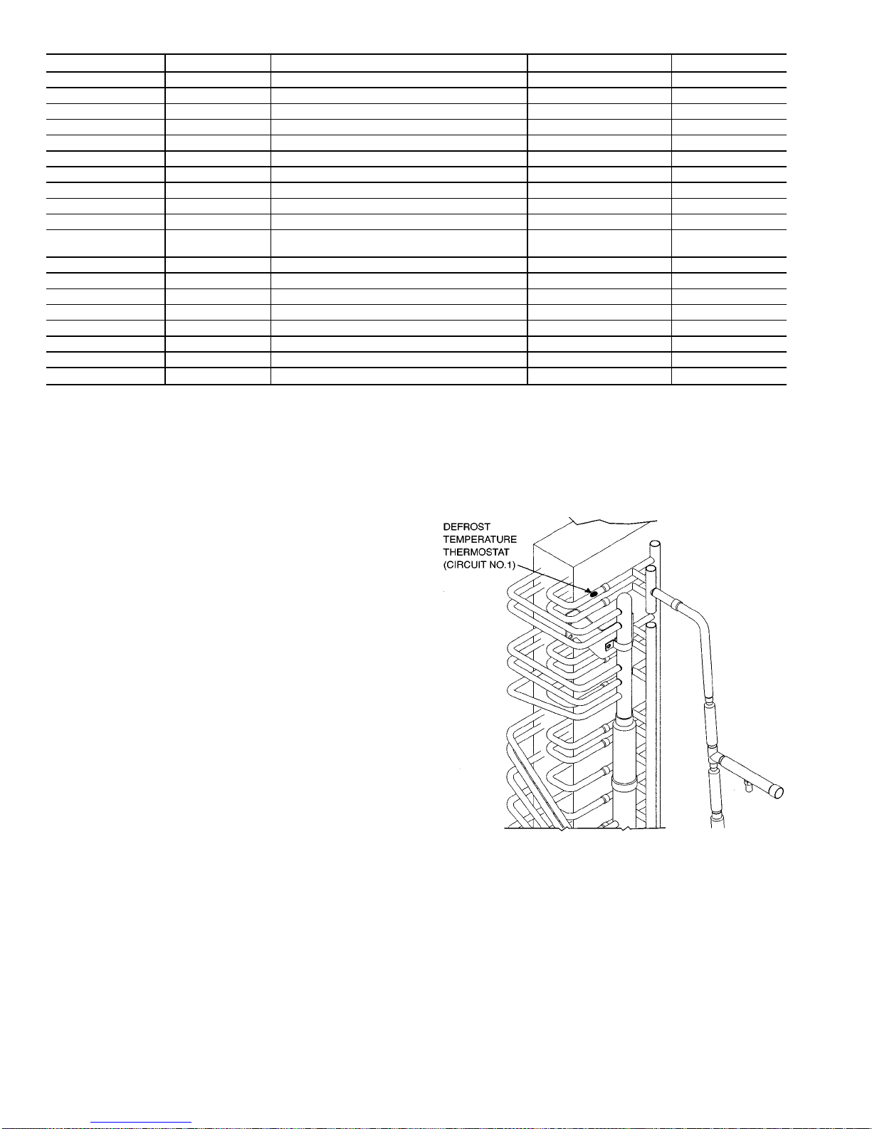
Table 14 — User Defined Set Points
SET POINT FORMAT DESCRIPTION LIMITS DEFAULT
OHSP xx.xF Occupied Heat Set Point 55 to 80 F 68 F
OCSP xx.xF Occupied Cool Set Point 55 to 80 F 78 F
UHSP xx.xF Unoccupied Heat Set Point 40 to 80 F 55 F
UCSP xx.xF Unoccupied Cool Set Point 75 to 95 F 90 F
SASP xx.xF SupplyAir Set Point 45 to 70 F 55 F
OATL xx.xF Hi OAT Lockout Temperature 55 to 75 F 65 F
NTLO xx.xF Unoccupied OAT Lockout Temperature 40 to 70 F 50 F
RTIO xx.x Reset Ratio 0 to 10 N/A
LIMT xx.x^F Reset Limit 0 to 20° F N/A
MDP xxx% Minimum Damper Position 0 to 100% N/A
LOWMDP xxx%
Low Temperature Minimum
Damper Position Override
0 to 100% 100%
IAQS xxxx IAQ Set Point 1 to 5000 ppm 650 ppm
UHDB xx.x^F Unoccupied Heating Deadband 0 to 10° F 1° F
UCDB xx.x^F Unoccupied Cooling Deadband 0 to 10° F 1° F
LTMP xxx% Low Temp. Min. Position 0 to 100% 10%
HTMP xxx% High Temp. Min. Position 0 to 100% 35%
PES1 xxx% CV Power Exhaust Stage 1 Point 0 to 100% 25%
PES2 xxx% CV Power Exhaust Stage 2 Point 0 to 100% 75%
DEFRTIME xxmin. Defrost Cycle Time 30 to 90 minutes 50 minutes
LEGEND
CV — Constant Volume
IAQ — Indoor Air Quality
N/A — Not Available
OAT — Outdoor-Air Temperature
NOTE: Computer access may be required to change set points.
Heating — The control module is powered by 24 vac. If
the unit is controlled with a room sensor, the fan will run
continuously in the Occupied mode,with the outside-air damper
in the minimum position. If the unit is controlled through a
room thermostat (with FAN set to AUTO), upon a call for
heat the first stage heat is energized, energizing reversing
valve solenoids (RVS1 and 2). Compressor no. 1 and 2, indoor and outdoor-fan motors start. Upon a call for additional
heat (if equipped with electric heaters), the second stage of
heat is energized. When the call for heat is satisfied, the compressors, fan motors, and heaters will be deenergized and
the outdoor-air damper will move to the closed position.
If the unit is controlled with a room sensor the fan will
not run in the Unoccupied mode unless the space temperature is below the unoccupied heat set point or above the
unoccupied cool set point. Upon a call for heat, the first
stage of heat is energized, energizing reversing valve solenoids (RVS1 and 2). Compressor no. 1 and 2, indoor and
outdoor-fanmotors start, and the outdoor-air damper will move
to the Unoccupied IAQ position (generally set to zero in the
Unoccupied mode). The IAQ feature is enabled through system software. Upon a call for additional heat (if equipped
with electric heaters), the second stage of heat is energized.
When the call for heat is satisfied, the compressors, fan
motors, and heaters will be deenergized and the outdoor-air
damper will move to the closed position.
Defrost Cycle — When the temperature of the outdoor
coil drops below 28 F as sensed by the defrost thermostat
(DFT1 or 2) and the defrost timer is at the end of a timed
period (adjustable at 30 to 90 minutes) the defrost cycle will
begin. See Fig. 34. The control board will deenergize the
reversing valve solenoids (RVS1 and 2) and energize the electric heat. Also, the outdoor-fan motor will stop.
The unit will continue to defrost until the coil temperature
as measured by DFT1 and 2 reaches 65 F or the duration of
defrost cycle completes a 10-minute period.
During the defrost mode, if a circuit defrosts first, the RVS
will oscillate between heating and cooling modes until defrost mode is complete. This will keep the head pressure on
that circuit from getting too high.
At the end of the defrost cycle, the electric heaters will be
deenergized, reversing valve solenoids will be energized, and
the outdoor fan will start.
Fig. 34 — Defrost Temperature
Thermostat Location
26
Page 27
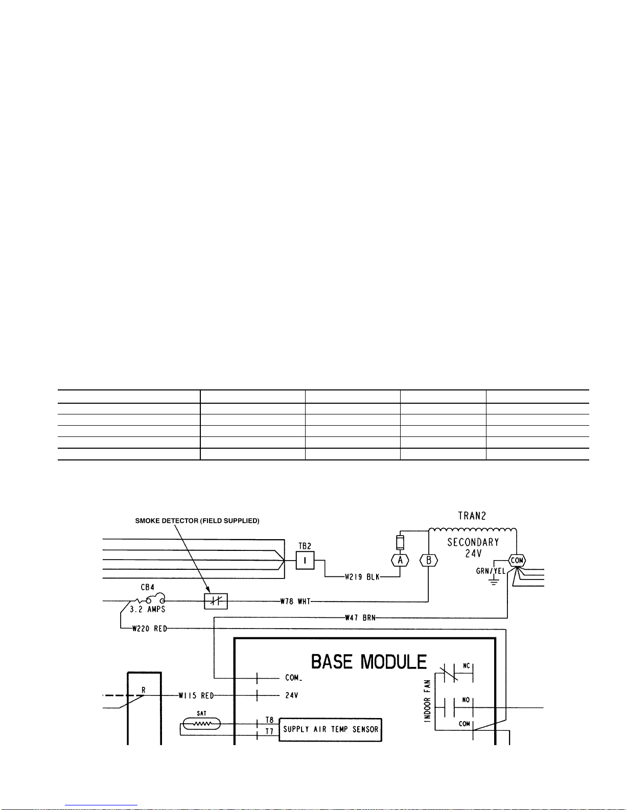
POWER EXHAUST OPERATION — The optional power
exhaust packages are factory- or field-installed with vertical units and optionally installed in the return air ductwork
for horizontal applications. The standard and optional
modulating power exhaust are the 2 packages available. The
modulating power exhaust package is equipped with a fieldadjustable static pressure controller which will control up to
4 power exhaust stages to maintain a building static pressure. The blue sequencer located in the control box below
the control board can be adjusted by removing the covers
and adjusting the set point dial to the desired building pressure. The standard power exhaust package controls up to
2 stages of power exhaust to maintain building pressure. These
power exhaust stages are staged according to a percentage
of the economizer damper position. The default values are
25% for Stage 1 and 75% for Stage 2. This package has set
points that are adjustable through software (such as Service
Tool, Building Supervisor, or ComfortWorks™).
NOTE: For 50EWQ applications, the factory-supplied wiring harness will allow for return duct mounting of the power
exhaust assembly within 12 ft of the unit. The harness is
approximately 16 ft long.
SMOKE CONTROL MODES — The 50EJQ,EWQ units with
an optional expansion board perform fire and smoke control
modes. The expansion board provides 4 modes which can
be used to control smoke within the conditioned area. The
modes of operation are fire shutdown, pressurization, evacuation, and smoke purge. See Table 15.
SMOKE DETECTOR — A smoke detector can be used to
initiate fire shutdown. This can be accomplished by a set of
normally closed pilot relay contacts which will interrupt power
from the 24-v transformer, secondary ‘‘B’’ terminal to the
control circuit breaker (CB4). See Fig. 35. The wire that connects these two points is white and labeled ‘‘W78.’’
The smoke detector may be mounted in the return-air duct
or the supply duct. Carrier does not make recommendations
as to specific smoke detector location due to liability
considerations.
IAQ CONTROL — The accessory expansion board and
accessory IAQ sensor are required for IAQ control. The
Carrier sensors operate witha4to20mAsignal. The 4
to 20 mA signal is connected to T11 (+) and T12 (−) on
the expansion board for the IAQ sensor, and T13 (+) and
T14 (−) on the expansion board for the OAQ sensor. The
sensor is field-mounted and wired to the expansion board
installed in the unit main control box. The IAQ sensor must
be powered by a field-supplied 24-v power supply (ungrounded). Do not use the unit 24-v power supply to power
the sensor.
Once installed, the sensor must be enabled. The sensor is
configured with default values which may be changed through
network access software. To work properly, the IAQ sensor
high and low reference points for the sensor that is used must
match the configured values. The expansion board reacts to
a 4 to 20 mA signal from the IAQ sensor.The low reference
(4 mA output) must be configured to the minimum IAQ
sensor reading. The high reference (20 mA output) must be
configured to the maximum IAQ sensor reading.
Table 15 — Smoke Control Modes
DEVICE PRESSURIZATION SMOKE PURGE EVACUATION FIRE SHUTDOWN
Economizer 100% 100% 100% 0%
Indoor Fan/VFD ON ON OFF OFF
Power Exhaust (all outputs) OFF ON ON OFF
Heat Stages OFF OFF OFF OFF
HIR ON ON OFF OFF
LEGEND
HIR — Heat Interlock Relay
VFD — Variable Frequency Drive
Fig. 35 — Smoke Detector Wiring
27
Page 28
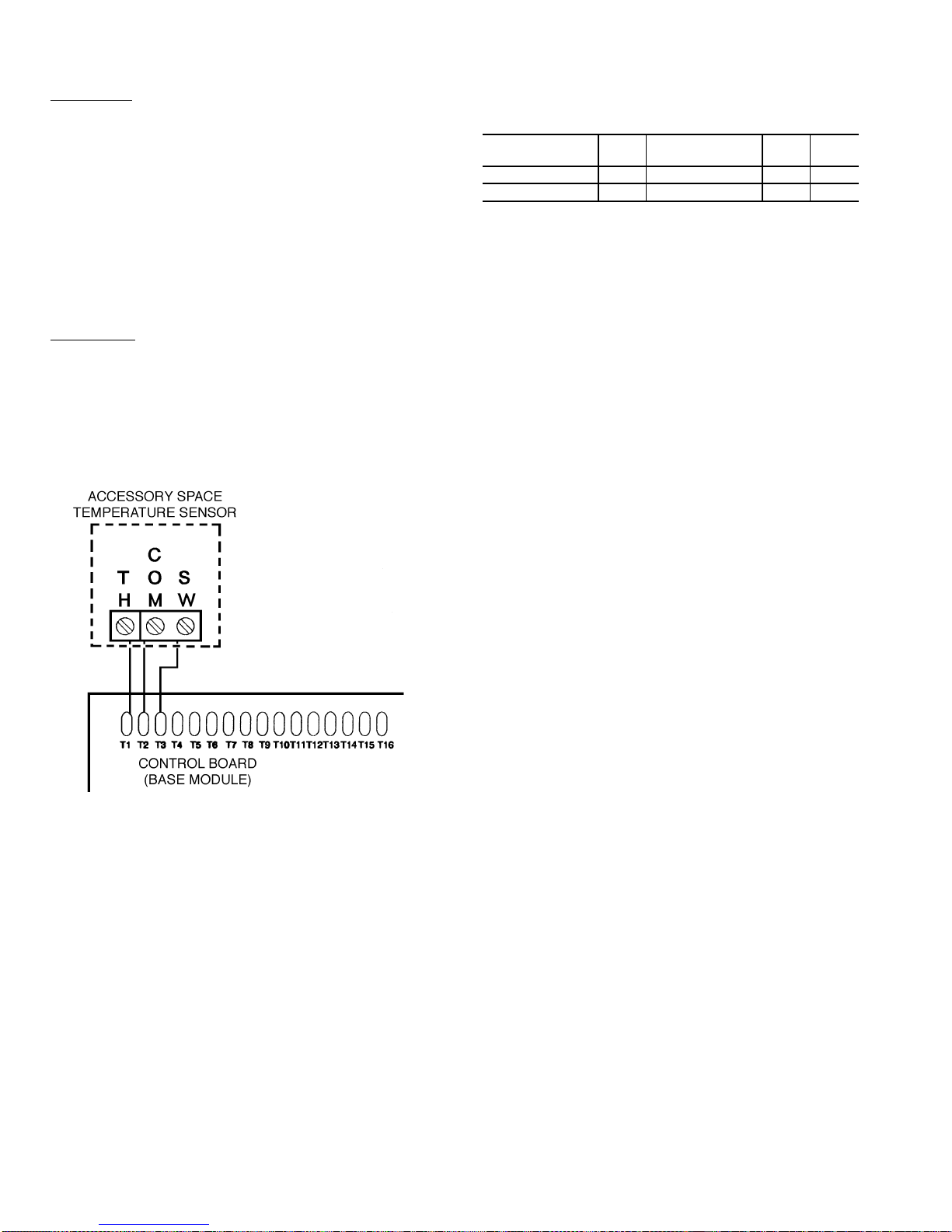
The IAQ sensor can be configured to either low or high
priority. The priority value can be changed by the user. The
default is low.
Low Priority — When the priority is set to low, the initial
control is to the IAQ set point, but the outside air damper
position will change to its minimum position when the following conditions occur:
• units with sensor — when the space temperature is greater
than the occupied cooling set point plus 2° F or when the
space temperature is less than the occupied heating set point
minus 2° F.
• units with thermostat — when the supply-air temperature
is less than the supply-air temperature set point minus
8° F or when the supply-air temperature is greater than the
supply air temperature set point plus 5° F for 4 minutes.
• When the outdoor air quality is greater than the outdoor
air quality set point (ppm)
High Priority — When the priority is set to high, the IAQ
set point controls the outside air damper exclusively, with
no regard to comfort conditioning.
SPACE TEMPERATURE OFFSET — An accessory space
temperature sensor (T-56) will allow an offset of the space
temperature set point ± 5° F. The 4 to 20 mA signal corresponds to a 0° to 20° F offset. The reset ratio set point is
used to modify the offset temperature range. See Fig. 36 for
space temperature sensor wiring.
DISABLINGTHE ECONOMIZER — For applications where
the economizer will not be used (areas of high humidity),
the economizer will need to be disabled. Be sure to turn off
electrical power before attempting this procedure. The economizer is best disabled by breaking the splice connecting the
violet wire coming from T24 on the base module board and
the red wire coming from T29 on the base module board.
The splice is made where the OAT (outdoor air thermistor) is located (at the right hand outdoor air damper area).
Remove the wire nut from the violet to red wire splice. Cap
off both wires so the connection is broken. When the connection is broken, the base module is fooled into thinking
that the enthalpy is not acceptable and economizer operation
is disabled.
CAPACITY CONTROL, COOLING — The cooling capacity staging table is shown in Table 16.
Table 16 — Cooling Capacity Staging Table,
Units with 2 Compressors
STAGES 0
1
ECONOMIZER
23
Compressor 1 Off Off On On
Compressor 2 Off Off Off On
NOTE: On units that require additional unloading, add suction pressure unloaders on Compressor 1 only.
FIELD TEST — The field test program is initiated by moving up DIP switch no. 4 to the OPEN position. The outdoorair damper will close. The control allows 90 seconds for the
damper to close in case it was in the full open position. Next,
the indoor-fan contactor will be energized, and the outsideair damper will begin to open to its default value of 20% and
stay at that position for a short period of time. The outdoorair damper will then open to its full open position and stay
at that position for a short period of time. The outdoor-air
damper will then close.
If the unit is equipped with power exhaust, stage 1 will be
energized for 5 seconds. If the unit is configured for stage 2
of power exhaust, stage 2 will be energized for 5 seconds
after the first stage is deenergized.
The first stage of heat will be energized for 30 seconds,
after which the second stage heat will be energized for an
additional 30 seconds. Heat is then deenergized.
The last step is the Cooling mode. Outdoor-fan contactor
no. 1 is energized. This is followed by each stage of cooling
energized with a 10-second delay between stages. After this
is complete, outdoor-fan contactor no. 2 is energized for
10 seconds.
The compressors will now deenergize, followed by the
outdoor-fan contactors and indoor-fan contactors.
The field test is then complete.
TIME GUARDt CIRCUIT — The TimeGuard function (built
into the unit control module board) maintains a minimum
offtime of 5 minutes and a minimum on time of 10 seconds.
CRANKCASE HEATER— The unit main power supply must
remain on to provide crankcase heater operation. The crankcase heater in each compressor keeps oil free of refrigerant
while compressor is off.
HEAD PRESSURE CONTROL — Each unit has a fan
cycling, outdoor thermostat to shut off outdoor-fan motor(s)
at 55 F. The head pressure control permits the unit to operate
with correct condensing temperatures down to 35 F outdoorair temperature if the economizer is disabled.
MOTORMASTERt III DEVICE — The Motormaster III
Solid-State Head Pressure Control is a field-installed accessory, fan speed control device actuated by a temperature
sensor. The Motormaster III device is specifically designed
for use on Carrier equipment and controls the outdoorfan motor speed in response to the saturated condensing
temperature. For outdoor temperatures down to −20 F, the
Motormaster III device maintains condensing temperature at
100 F.
NOTE: Sensor part number is CEC0121503-01.
Fig. 36 — Space Temperature Sensor Wiring
28
Page 29
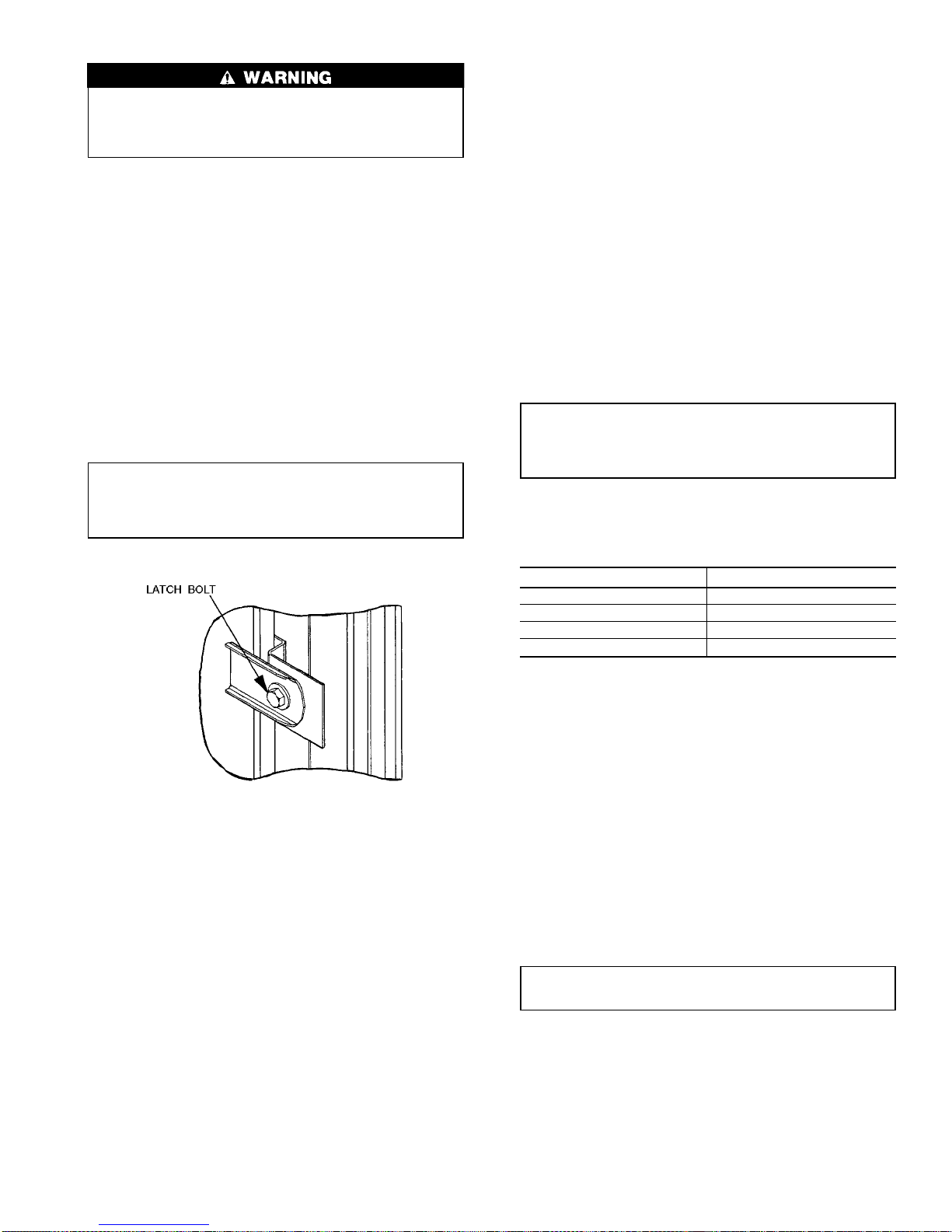
SERVICE
Before performing service or maintenance operations on
unit, turn off main power switch to unit. Turn off accessory heater power switch if applicable. Electrical shock
could cause personal injury.
ServiceAccess — All unit components can be reached
through clearly labelled hinged access doors. These doors
are not equipped with tiebacks, so if heavy duty servicing is
needed, either remove them or prop them open to prevent
accidental closure.
Each door is held closed with 3 latches. The latches are
secured to the unit with a single
1
⁄4-in.-20x1⁄2-in. long bolt.
See Fig. 37.
To open, loosen the latch bolt using a
7
⁄16-in. wrench. Pivot
the latch so it is not in contact with the door. Open the door.
To shut, reverse the above procedure.
NOTE: Disassembly of the top cover may be required under
special service circumstances. It is very important that the
orientation and position of the top cover be marked on the
unit prior to disassembly. This will allow proper replacement of the top cover onto the unit and prevent rainwater
from leaking into the unit.
IMPORTANT:After servicing is completed, make sure
door is closed and relatched properly, and that the latches
are tight. Failure to do so can result in water leakage
into the evaporator section of the unit.
Cleaning— Inspect unit interior at beginning of each heat-
ing and cooling season and as operating conditions require.
Remove unit top panel and/or side panels for access to unit
interior.
INDOOR COIL — Clean as required with a commercial coil
cleaner.
OUTDOOR COIL — Clean outdoor coil annually and as
required by location and outdoor-air conditions. Inspect coil
monthly — clean as required.
CONDENSATE DRAIN — Check and clean each year at
start of cooling season. In winter, keep drains and traps dry.
FILTERS — Clean or replace at start of each heating and
cooling season, or more often if operating conditions require. Refer to Table 1 for type and size.
NOTE: The unit requires industrial grade throwaway filters
capable of withstanding face velocities up to 625 fpm.
OUTDOOR-AIR INLET SCREENS — Clean screens with
steam or hot water and a mild detergent. Do not use throwaway filters in place of screens.
Lubrication
COMPRESSORS — Each compressor is charged with the
correct amount of oil at the factory. The correct oil charge is
shown in Table 1. If oil is visible in the compressor sight
glass, check unit for operating readiness as described in Start-Up
section, then start the unit. Observe oil level and add oil, if
required, to bring oil level in compressor crankcase up to
between1⁄4and1⁄3of sight glass during steady operation.
If oil charge is above
1
⁄3sight glass, do not remove any oil
until the compressor crankcase heater has been energized for
at least 24 hours with compressor off.
When additional oil or a complete charge is required, use
only Carrier-approved compressor oil:
Petroleum Specialties, Inc. .................Cryol 150
Texaco, Inc. .........................Capella WF-32
Witco Chemical Corp. ...................Suniso 3GS
IMPORTANT: Do not use reclaimed oil or oil that has
been exposed to the atmosphere. Refer to Carrier Standard Service Techniques Manual, Chapter 1, Refrigerants section, for procedures to add or remove oil.
FAN SHAFT BEARINGS — Lubricate the bearings at least
twice annually with suitable bearing grease. Do not over grease.
Typical lubricants are show below:
MANUFACTURER LUBRICANT
Texaco Regal AFB-2*
Mobil Mobilplex EP No. 1
Sunoco Prestige 42
Texaco Multifak 2
*Preferred lubricant because it contains rust and oxidation inhibitors.
OUTDOOR AND INDOOR-FAN MOTOR BEARINGS —
The outdoor and indoor-fan motors have permanentlysealed bearings, so no field lubrication is necessary.
Indoor Fan Performance Adjustment (Fig. 38)
—
Fan motor pulleys are factory set for speed shown in
Table 1 (factory speed setting).
To change fan speeds, change pulleys.
To align fan and motor pulleys:
1. Shut off unit power supply.
2. Loosen fan shaft pulley bushing.
3. Slide fan pulley along fan shaft.
4. Make angular alignment by loosening motor from mount-
ing plate.
5. Retighten pulley.
IMPORTANT: Check to ensure that the unit drive
matches the duct static pressure in Table 11.
Indoor Fan Service and Replacement
1. Turn off unit power.
2. Remove supply-air section panels.
3. Remove belt and blower pulley.
4. Loosen set screws in blower wheels.
5. Remove locking collars from bearings.
Fig. 37 — Door Latch
29
Page 30
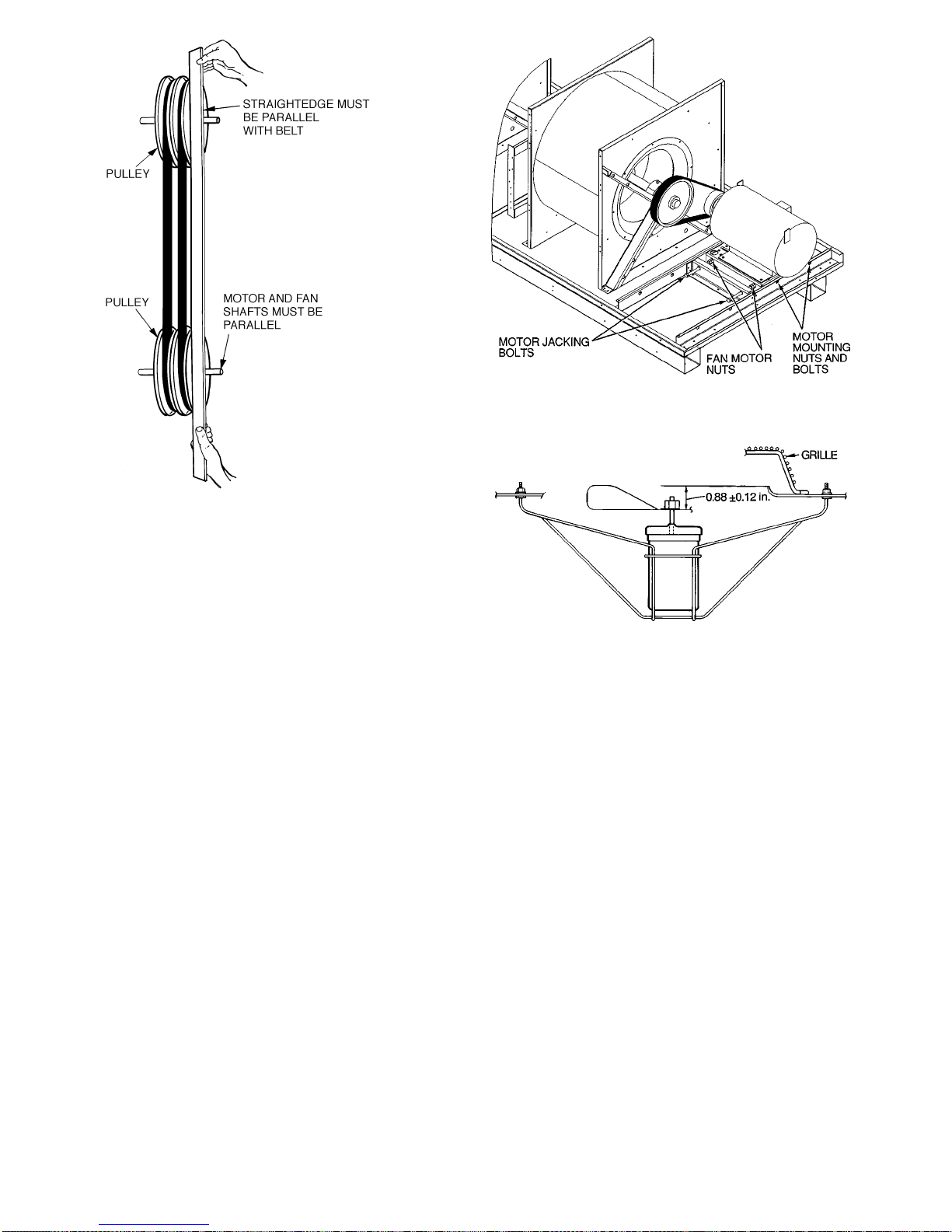
6. Remove shaft.
7. Remove venturi on opposite side of bearing.
8. Lift out wheel.
9. Reverse above procedure to reinstall fan.
10. Check and adjust belt tension as necessary.
Belt Tension Adjustment — To adjust belt tension:
1. Remove power to unit.
2. Remove motor mount nuts and bolts.
3. Loosen fan motor nuts. See Fig. 39.
4. Turn motor jacking bolts to move motor mounting plate
left or right for proper belt tension. A slight bow should
be present in the belt on the slack side of the drive while
running under full load.
5. Tighten nuts.
6. Adjust bolts and nut on mounting plate to secure motor
in fixed position. Recheck belt tension after 24 hours of
operation. Adjust as necessary.
Outdoor-Fan Adjustment
1. Shut off unit power supply.
2. Remove fan guard.
3. Loosen fan hub setscrews.
4. Adjustfan height on shaft using a straightedge placed across
venturi and measure per Fig. 40.
5. Tighten setscrews and replace fan guard.
6. Turn on unit power.
Indoor-Fan Motor Replacement
1. Shut off unit power supply.
2. Remove upper outside panel and open hinged door to
gain access to motor.
3. Fully retract motor plate adjusting bolts.
4. Loosen the 2 rear (nearest the indoor coil) motor plate
nuts.
5. Remove the 2 front motor plate nuts and carriage bolts.
6. Slide motor plate to the rear (toward the coil) and remove fan belt(s).
7. Slide motor plate to the front and hand tighten one of
the rear motor plate nuts (tight enough to prevent the
motor plate from sliding back but loose enough to allow
the plate to pivot upward).
8. Pivot the front of the motor plate upward enough to
allow access to the motor mounting hex bolts and
secure in place by inserting a prop.
9. Remove the nuts from the motor mounting hex bolts and
remove motor.
10. Reverse above steps to install new motor.
PowerFailure — Dampers have a spring return. In event
of power failure, dampers will return to fully closed position
until power is restored.
Refrigerant Charge — Amount of refrigerant charge
is listed on unit nameplate and in Table 1. Refer to Carrier
GTAC II; Module 5; Charging, Recovery, Recycling, and
Reclamation section for charging methods and procedures.
Unit panels must be in place when unit is operating dur-
ing charging procedure.
Fig. 38 — Indoor-Fan Alignment and Adjustment
Fig. 39 — Belt Tension Adjustment
Fig. 40 — Outdoor-Fan Adjustment
30
Page 31
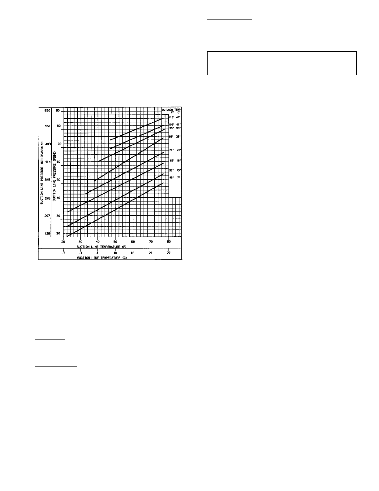
NO CHARGE — Use standard evacuating techniques. After
evacuating system, weigh in the specified amount of refrigerant (refer to Table 1).
LOW CHARGE COOLING — Using cooling charging chart
(see Fig. 41), add or remove refrigerant until conditions of
the chart are met. Indoor-air cfm must be within normal operating range of unit. Take outdoor ambient temperature and
read the suction pressure gage. Refer to chart to determine
correct suction temperature. If intersection point on chart is
above the curve, add refrigerant. If intersection point on chart
is below curve, carefully recover some of the charge. Recheck suction pressure as charge is adjusted.
Filter Drier — Replace whenever refrigerant system is
exposed to atmosphere.
Protective Devices
COMPRESSOR PROTECTION
Overcurrent — Each compressor has one manual reset, cali-
brated trip, magnetic circuit breaker. Do not bypass connections or increase the size of the circuit breaker to correct trouble.
Determine the cause and correct it before resetting the breaker.
Overtemperature — Each 06D type compressor has an internal protector to protect it against excessively high discharge gas temperatures.
Crankcase Heater — Each compressor has a crankcase heater
to prevent absorption of liquid refrigerant by oil in the crankcase when the compressor is idle. Since power for the crankcase heaters is drawn from the unit incoming power, main
unit power must be on for the heaters to be energized.
IMPORTANT: After a prolonged shutdown or service job, energize the crankcase heaters for 24 hours
before starting the compressors.
INDOOR-FAN MOTOR PROTECTION — A manual reset,
calibrated trip, magnetic circuit breaker protects against overcurrent. Do not bypass connections or increase the size of
the breaker to correct trouble. Determine the cause and correct it before resetting the breaker. If the indoor-fan motor is
replaced with a different horsepower motor, resizing of the
circuit breaker is required. Contact Carrier Application
Engineering.
OUTDOOR-F ANMOTORPROTECTION — Each outdoorfan motor is internally protected against overtemperature.
HIGH- AND LOW-PRESSURE SWITCHES — If either
switch trips, or if the compressor overtemperature switch
activates, that refrigerant circuit will be automatically locked
out. To reset, manually move the thermostat setting.
FREEZE PROTECTION THERMOSTAT (FPT) — Freeze
protection thermostats are located on the evaporator coil for
each circuit. One is located at the top and bottom of each
coil. It detects frost build-up and turns off the compressor,
allowing the coil to clear .Once the frost has melted, the compressor can be reenergized.
Relief Devices — All units have relief devices to pro-
tect against damage from excessive pressures (i.e., fire). These
devices are installed on the suction line, liquid line, and on
the compressor.
Control Circuit, 24-V — This control circuit is pro-
tected against overcurrent by a 3.2-amp circuit breaker (CB4).
Breaker can be reset. If it trips, determine cause of trouble
before resetting. See Fig. 42.
Control Circuit, 115-V — This control circuit is pro-
tected against overcurrent by a 5.0-amp circuit breaker (CB3).
Breaker can be reset. If it trips, determine cause of trouble
before resetting.
Compressor Lockout Logic — If any of the safe-
ties trip, the circuit will automatically reset (providing the
safety has reset) and restart the compressor in 15 minutes. If
any of the safeties trip 3 times within a 90-minute period,
then the circuit will be locked out and will require manual
resetting by turning off either the unit disconnect or the control circuit breaker, or opening the thermostat.
Replacement Parts — A complete list of replacement
parts may be obtained from any Carrier distributor upon
request.
Fig. 41 — Cooling Charging Chart,
Sizes 024,028
31
Page 32
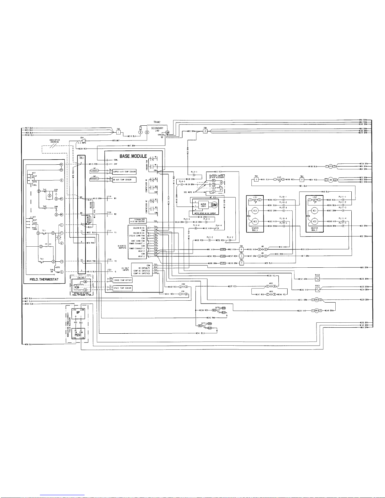
Fig. 42 — Typical 24-V Control Schematic
32
Page 33
LEGEND FOR FIG. 42
AHA — Adjustable Heat Anticipator
BP — Building Pressure
CB — Circuit Breaker
CC — Cooling Compensator
COM — Communication
COMP — Compressor Motor
COMPR — Compressor Motor
COND — Condenser
CONT — Continuous
CR — Control Relay
DFT — Defrost Thermostat
DM — Damper Motor
EC — Enthalpy Control
FU — Fuse
HC — Heater Contactor
HR — Heater Relay
IFR — Indoor-Fan Relay
L—Light
LS — Limit Switch
NC — Normally Closed
NO — Normally Open
OD — Outdoor
PESC — Power Exhaust Sequencer Controller
PL — Plug Assembly
R—Relay
RVS — Reversing Valve Solenoid
SW — Switch
TB — Terminal Block
TC — Thermostat Cooling
TH — Thermostat Heating
TRAN — Transformer
Terminal (Marked)
Terminal (Unmarked)
Terminal Block
Splice
Factory Wiring
Field Wiring
To indicate common potential
only, not to represent wiring
33
Page 34
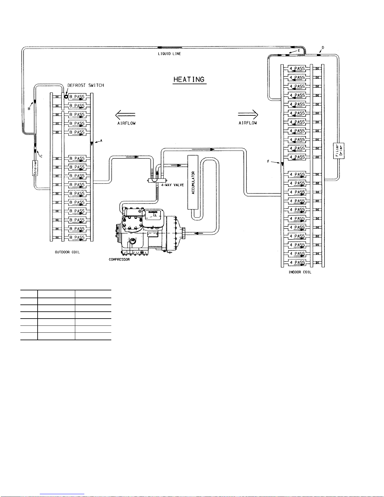
TROUBLESHOOTING
Typical heating and cooling refrigerant circuiting diagrams are shown in Fig. 43 and 44.
CHECK VALVES
COOLING HEATING
A Closed Open
B Open Closed
C Closed Open
D Open Closed
E Closed Open
F Open Closed
NOTES:
1. Hot gas from compressor flows through the 4-way valve and is directed to the
indoor coil header. At the header it is condensed and subcooled. Refrigerant leaves
the indoor coil by way of the check valve to the liquid line.
2. The refrigerant then flows through a strainer and feeds the outdoor coil by way of fixed
orifice tubes on each circuit.
3. Each circuit evaporates the refrigerant, and the circuits are combined in the outdoor
coil header with some of the circuits flowing through the check valve.
4. The refrigerant then flows through the 4-way valve, accumulator, and back to the
compressor.
Fig. 43 — Typical Refrigerant Circuiting (Heating)
34
Page 35
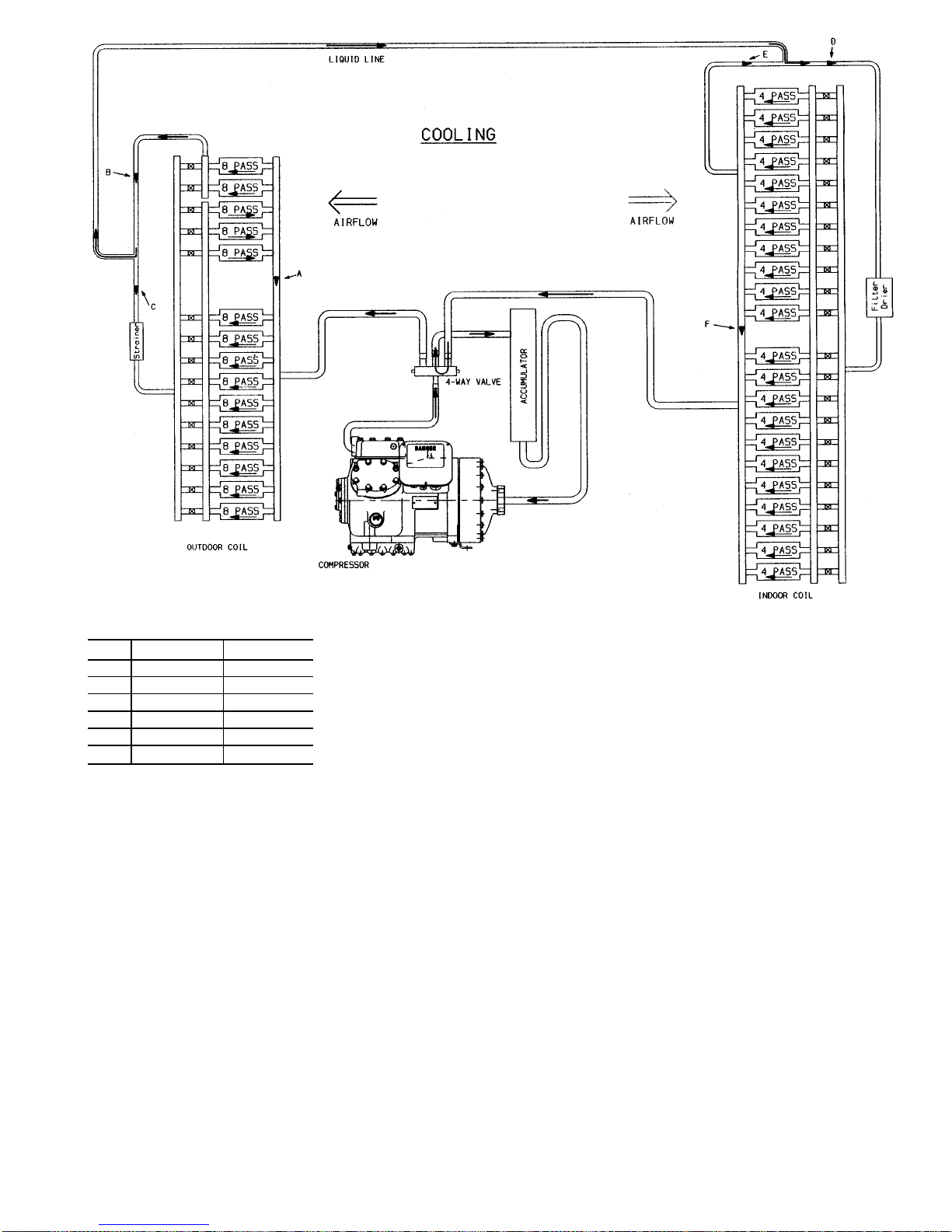
DiagnosticLEDs (Light-Emitting Diodes) — There
are 3 LEDs (red, yellow, and green) on the lower left hand
side of the control board. The red light is used to check
unit operation and alarms. A constant pulse is normal unit
operation. A series of quick blinks indicates an alarm. Refer
to Table 17 on next page for a description of alarms. The
yellow LED blinks during transmission with the CCN
(Carrier Comfort Network). The green LED blinks during
transmission with the expansion board.
Channel Designations — Tables 18 and 19 show the
input and output channel designations.
CHECK VALVES
COOLING HEATING
A Closed Open
B Open Closed
C Closed Open
D Open Closed
E Closed Open
F Open Closed
NOTES:
1. Hot gas from compressor flows through the 4-way valve and is directed to the
outdoor coil header. At the header it is condensed and subcooled through converging
circuits (10-3-2). Refrigerant leaves the outdoor coil by way of the check valve to the
liquid line.
2. The refrigerant then flows through the filter drier and feeds the indoor coil by way of
fixed orifice tubes on each circuit.
3. Each circuit evaporates the refrigerant, and the circuits are combined in the indoor coil
header with some of the circuits flowing through the check valve.
4. The refrigerant then flows through the 4-way valve, accumulator and back to the
compressor.
Fig. 44 — Typical Refrigerant Circuiting (Cooling)
35
Page 36
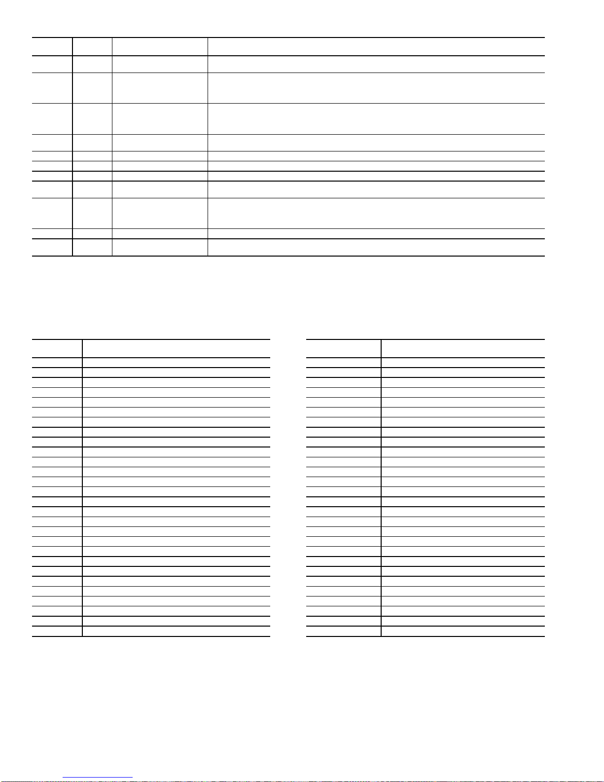
Table 17 — Control Board LED Alarms
LED
BLINKS
ERROR
CODE
DESCRIPTION
TROUBLESHOOTING
COMMENTS
1 — Normal Operation
The expansion board and control board flash the red LED in one-second intervals when the board is
operating properly.
2 HF-13 Compressor 1 Safety
The high or low pressure safety switch for compressor no. 1 has opened for 3 seconds. The error will
be cleared and compressor no. 1 will be allowed to turn on in 15 minutes. If the safeties have been
tripped 3 times in 90 minutes, compressor no. 1 will be locked out until the control board has been
manually reset.
3 HF-14 Compressor 2 Safety
The high or low pressure safety switch for compressor no. 2 has opened for 3 seconds. The error will
be cleared and compressor no. 2 will be allowed to turn on in 15 minutes. If the safeties have been
tripped 3 times in 90 minutes, compressor no. 2 will be locked out until the control board has been
manually reset.
4 HF-15 Thermostat Failure
The thermostat is calling for both heating and cooling at the same time. The unit will operate on a first
call basis and will automatically reset.
5 HF-05 SAT Thermistor Failure The supply-air temperature (SAT) sensor has failed. First check for wiring errors, then replace sensor.
6 HF-06 OAT Thermistor Failure The outside-air temperature (OAT) sensor has failed. First check for wiring errors, then replace sensor.
7 HF-03 Space Temp. Sen. Failure The space temperature sensor has failed. First check for wiring errors, then replace sensor.
8 HF-12 RAT Thermistor Failure
The return-air temperature (RAT) sensor has failed. Ensure that DIP switch position 1 is in the closed
position and reset power. Then check for wiring errors. Finally, replace sensor.
9 SE-05
Loss of Communications
with Expansion board
Communications between the expansion board and the control board have been interrupted. Ensure
that an expansion board is installed and wired using the wire harness supplied with the expansion
module. If an expansion board is not used ensure that DIP switch position 3 is in the closed position,
and reset power.
10 HF-16 Control Board Failure Generated when hardware has failed on control board. Replace the control board.
11 HF-17 Expansion Board Failure
Generated when hardware has failed on the expansion board.
Replace the expansion board.
LEGEND
DIP — Dual In-Line Package
LED — Light-Emitting Diode
Table 18 — I/O Channel Designations
Base Module
TERMINAL
NO.
ASSIGNMENT
T1-2 SPT (CCN) — 10KV Thermistor
T3-4 STO (CCN) — 10KV Thermistor
T5-6 OAT — 5KV Thermistor
T7-8 SAT — 5KV Thermistor
T9-10 —
T11-12 —
T13-14 —
T15-16 —
T17-25 Y1 — DI (24 vac)
T18-25 Y2 — DI (24 vac)
T19-25 W1 or Remote Start/Stop — DI (24 vac)
T20-25 W2 — DI (24 vac)
T21-25 G — DI (24 vac)
T22-25 Compressor 1 Safety — DI (24 vac)
T23-25 Compressor 2 Safety — DI (24 vac)
T24-25 Outside Air Enthalpy — DI (24 vac)
T26-27 Economizer Pos. — AO (4-20 mA)
T28-29 Heat 1 Relay — DO (24 vac)
T30-29 Heat 2 Relay — DO (24 vac)
T31-32 Power Exhaust 1/Modulating Pwr Exht — DO (115 vac)
T33-32 Power Exhaust2—DO(115vac)
T34-35 Condenser Fan — DO (115 vac)
T36-35 OFC2 — DO (115 vac)
T37-38 Reversing Valve Solenoid No. 1
T39-38 Reversing Valve Solenoid No. 2
K1 Indoor Fan Relay — DO (LV)
K2 Compr.1—DO(HV)
K3 Compr.2—DO(HV)
LEGEND
AO — Analog Output OAT — Outdoor-Air Temperature
CCN — Carrier Comfort Network OFC — Outdoor Fan Contactor
DI — Direct Input SAT — Supply-Air Temperature
DO — Direct Output SPT — Space Temperature
HV — High Voltage STO — Space Temperature Offset
KV — Kilo-Ohms T—Terminal
LV — Low Voltage
NOTE: For all 4 to 20 mA signals, all even numbered terminals are negative (−)
polarity, and all odd numbered terminals are positive (+) polarity.
Table 19 — I/O Channel Designations Expansion
Module
TERMINAL
NO.
ASSIGNMENT
T1-2 —
T3-4 —
T5-6 —
T7-8 —
T9-10 —
T11-12 IAQ Indoor — AI (4-20 mA)
T13-14 IAQ Outdoor — AI (4-20 mA)
T15-16 —
T17-25 Fan Status — DI (24 vac)
T18-25 Filter Status — DI (24 vac)
T19-25 Field Applied Status — DI (24 vac)
T20-25 Demand Limit — DI (24 vac)
T21-25 Fire — Unit Shutdown — DI (24 vac)
T22-25 Fire — Pressurization — DI (24 vac)
T23-25 Fire — Evacuation — DI (24 vac)
T24-25 Fire — Smoke Purge — DI (24 vac)
T26-27 —
T28-29 —
T30-29 Alarm Light Indicator — DO (24 vac)
T31-32 Power Exhaust Fire #1 — DO (115 vac)
T33-32 Power Exhaust Fire #2 — DO (115 vac)
T34-35 Power Exhaust Fire #3 — DO (115 vac)
T36-35 Power Exhaust Fire #4 — DO (115 vac)
T37-38 —
T39-38 —
K1 —
K2 —
K3 —
LEGEND
AI — Analog Input
DI — Direct Input
DO — Direct Output
IAQ — Indoor Air Quality
T—Terminal
NOTE: For all 4 to 20 mA signals, all even numbered terminals are negative (−)
polarity, and all odd numbered terminals are positive (+) polarity.
36
Page 37
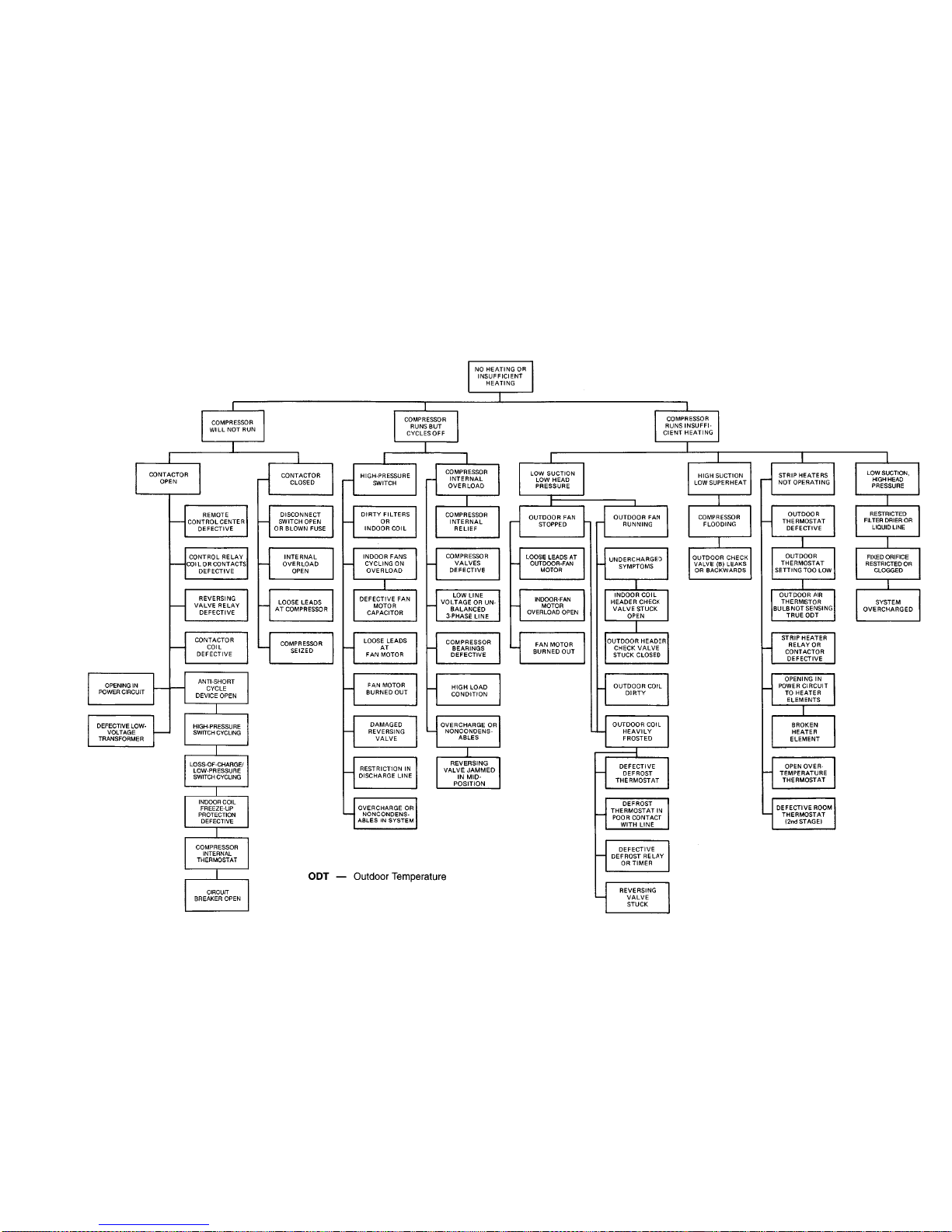
TROUBLESHOOTING CHART, HEATING CYCLE
37
Page 38
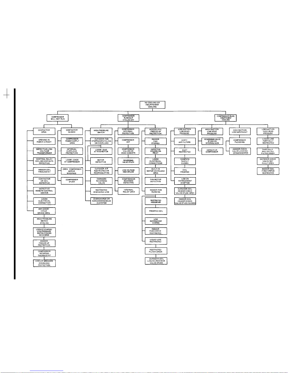
TROUBLESHOOTING CHART, COOLING CYCLE
Copyright 1997 Carrier Corporation
Manufacturer reserves the right to discontinue, or change at any time, specifications or designs without notice and without incurring obligations.
Book 1
Tab 5a
PC 111 Catalog No. 535-002 Printed in U.S.A. Form 50EJQ,EWQ-2SI Pg 38 8-97 Replaces: 50EJQ,EWQ-1SI
Page 39

START-UP CHECKLIST
MODEL NO.:
DATE:
SERIAL NO.:
TECHNICIAN:
PRE-START-UP:
M VERIFY THAT DIP SWITCH SETTINGS ARE CORRECT
M VERIFY THAT ALL PACKING MATERIALS HAVE BEEN REMOVED FROM UNIT
M REMOVE ALL SHIPPING HOLDDOWN BOLTS AND BRACKETS PER INSTRUCTIONS
M VERIFY INSTALLATION OF ECONOMIZER HOOD
M VERIFY INSTALLATION OF ALL OPTIONS AND ACCESSORIES
M VERIFY THAT CONDENSATE CONNECTION IS INSTALLED PER INSTRUCTIONS
M VERIFY THAT ALL ELECTRICAL CONNECTIONS AND TERMINALS ARE TIGHT
M CHECK THAT INDOOR-AIR FILTER IS CLEAN AND IN PLACE
M VERIFY THAT UNIT IS LEVEL WITHIN TOLERANCES
M CHECK FAN WHEELS AND PROPELLERS FOR LOCATION IN HOUSING/ORIFICE, AND VERIFY SET SCREW
IS TIGHT
M VERIFY THAT FAN SHEAVES ARE ALIGNED AND BELTS ARE PROPERLY TENSIONED
M VERIFY THAT SUCTION AND DISCHARGE SERVICE VALVES ON EACH CIRCUIT ARE OPEN
START-UP
ELECTRICAL
SUPPLY VOLTAGE L1-L2
L2-L3 L3-L1
COMPRESSOR AMPS — COMPRESSOR NO. 1 L1 L2 L3
— COMPRESSOR NO. 2 L1 L2 L3
SUPPLY FAN AMPS EXHAUST FAN AMPS
ELECTRIC HEAT AMPS (IF SO EQUIPPED) L1 L2 L3
TEMPERATURES
OUTDOOR-AIR TEMPERATURE
F DB (Dry-Bulb)
RETURN-AIR TEMPERATURE
FDB F WB (Wet-Bulb)
COOLING SUPPLY AIR
F
HEAT PUMP SUPPLYAIR
F
ELECTRIC HEAT SUPPLY AIR (IF SO EQUIPPED)
F
PRESSURES
REFRIGERANT SUCTION CIRCUIT NO. 1
PSIG CIRCUIT NO. 2 PSIG
REFRIGERANT DISCHARGE CIRCUIT NO. 1
PSIG CIRCUIT NO. 2 PSIG
M VERIFY REFRIGERANT CHARGE USING CHARGING CHART ON PAGE 31
CL-1
Page 40
START-UP CHECKLIST (cont)
GENERAL
M ECONOMIZER MINIMUM VENT AND CHANGEOVER SETTINGS TO JOB REQUIREMENTS
M ENSURE DRIVES OPERATE WITHIN LIMITS OF FAN PERFORMANCE TABLES
HIGH-PRESSURE SWITCH SETTING
PSIG
LOW-PRESSURE SWITCH SETTING
PSIG
MOTOR PULLEY PART NUMBER
FAN PULLEY PART NUMBER
BELT PART NUMBER
BELT SIZE in.
FILTER QUANTITY
FILTER SIZES in.
ADDITIONAL NOTES:
----------------------------------------------------------------------------------------
CUT ALONG DOTTED LINE CUT ALONG DOTTED LINE
Copyright 1997 Carrier Corporation
Manufacturer reserves the right to discontinue, or change at any time, specifications or designs without notice and without incurring obligations.
Book 1
Tab 5a
PC 111 Catalog No. 535-002 Printed in U.S.A. Form 50EJQ,EWQ-2SI CL-2 8-97 Replaces: 50EJQ,EWQ-1SI
 Loading...