

Carrier CRRFCURBXB3AA1, CRRFCURBXBABA1, CRRFCURBXB4AA1, CRRFCURBXB4BA1, CRRFCURBXB3BA1 Installation Instructions Manual
...Page 1
Dedicated Vertical or Horizontal Outdoor Air Unit
with Optional Energy Conservation Wheel
Roof Curb Accessory
Installation Instructions
Part Number CRRFCURBX****1
62X 03-35
SAFETY CONSIDERATIONS
Installation and servicing of air-conditioning equipment
can be hazardous due to system pressure and electrical
components. Only trained and qualified service personnel
should install, repair, or service air-conditioning equipment.
Untrained personnel can perform basic maintenance functions of cleaning coils and filters and replacing filters. All
other operations should be performed by trained service personnel. When working on air-conditioning equipment, observe precautions in the literature, tags and labels attached to
the unit, and other safety precautions that may apply.
Follow all safety codes, including ANSI (American National Standards Institute) Z223.1. Wear safety glasses and
work gloves. Use quenching cloth for unbrazing operations.
Have fire extinguisher available for all brazing operations.
WARNING
Electrical shock can cause personal injury and death. Shut
off all power to this equipment during installation. There
may be more than one disconnect switch. Tag all disconnect switch. Tag all disconnect locations to alert others not
to restore power until work is completed.
WARNING
PERSONAL INJURY AND EQUIPMENT DAMAGE
HAZARD
Failure to follow this warning could result in personal
injury and/or damage to equipment.
Do not leave roof opening uncovered. If installation
is not completed immediately after roof opening is cut
and framed, provide an adequate temporary cover for the
roof opening.
PACKAGE CONTENTS
Contents of packages will vary, but each curb will include
all curb frame, dividers, supports and hardware to completely
assemble curb. See attached curb assembly drawing for curb
details. For package usage see Table 1.
INSTALLATION
These instructions show a typical installation for 62X
curbs. A separate assembly drawing is provided with each
curb shipped. Use this drawing for job specific curb dimensions and construction.
There are two different types of roof curbs in the 62X series:
• The first is the standard curb without a separate equip-
ment support. These curbs are of varying sizes (see package usage) and have different types, sizes and quantities
of internal supports. Figures
examples of these curbs. Figure 1 has a 4 piece frame, 2
sides, and 2 ends. Figure 2 is a longer curb with 4 sides
and 2 ends.
These curbs should be assembled with provided corner
brackets and hardware as shown in Fig.
ger curbs (Fig. 2) have a splice in the length of the curb
sides. Install splice plate as shown in Fig. 2.
Install the supports in curb as shown on the drawing provided with the curb (quantity and location of the supports
vary by curb model).
• The second type of curb is the same as the first except it
also includes an equipment support. The assembly of the
curb itself will be the same as the first. The equipment
support is shipped assembled. Figure
curb with equipment support. The exact location of the
support is critical and is noted in 62X Installation
Instructions. The equipment support is known as a
sleeper rail and will support the condensing section of
the unit.
NOTE: For detailed information on the curb dimensions, refer to
the latest edition of Carrier's Dedicated Outdoor Air Systems
builder.
1. Before installing roof curb, ensure that curb is located so
that proper clearances are maintained. Ensure that roof
structural integrity is capable of supporting weight of
rooftop unit. Refer to structural unit nameplate or unit
installation instructions for correct clearances.
2. Cut hole in roof for duct openings per instructions pro-
vided with 62X unit.
3. Frame the roof opening to provide proper and adequate
structural support.
1 and 2 show 2 different
1 and 2. The lon-
3 shows a typical
Catalog No. 04-53620023-01 Printed in U.S.A. Form 62X-2SI Pg 1 7-18 Replaces: New
Manufacturer reserves the right to discontinue, or change at any time, specifications or designs without notice and without incurring obligations.
Page 2
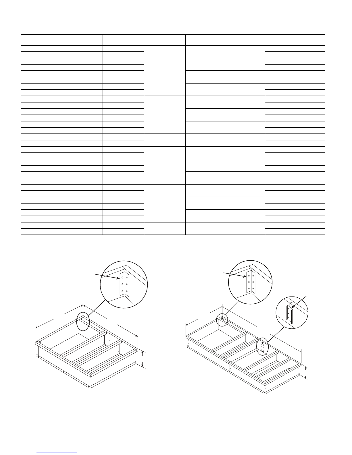
Table 1 — Package Usage
56 3/4"
66 1/8"
SIDE
END
CORNER
BRACKET
14
"
125 1/4"
56 3/4"
SIDE
SIDE
SIDE
END
CORNER
BRACKET
SPLICE
PLATE
14
"
CARRIER CURB PN
CRRFCURBXAAAA1 14
CRRFCURBXAABA1 14 With
CRRFCURBXBAAA1 14
CRRFCURBXBABA1 14 With
CRRFCURBXB3AA1 14
CRRFCURBXB3BA1 14 With†
CRRFCURBXB4AA1 14
CRRFCURBXB4BA1 14 With†
CRRFCURBXC2AA1 14
CRRFCURBXC2BA1 14 With
CRRFCURBXC3AA1 14
CRRFCURBXC3BA1 14 With
CRRFCURBXCBAA1 14
CRRFCURBXCBBA1 14 With†
CRRFCURBXDBAA1 14
CRRFCURBXDBBA1 14 With
CRRFCURBXBAAB1 14
CRRFCURBXBABB1 14 With
CRRFCURBXB3AB1 14
CRRFCURBXB3BB1 14 With†
CRRFCURBXB4AB1 14
CRRFCURBXB4BB1 14 With†
CRRFCURBXCAAB1 14
CRRFCURBXCABB1 14 With
CRRFCURBXCBAB1 14
CRRFCURBXCBBB1 14 With†
CRRFCURBXC3AB1 14
CRRFCURBXC3BB1 14 With
CRRFCURBXDCAB1 14
CRRFCURBXDCBB1 14 With
* Sleeper rail is included with any unit that has 3 or more condensing
fans.
† ERV not available on B cabinet with 3 or 4 condenser fans or C
cabinet with 6 condenser fans.
HEIGHT
(in.)
CABINET
B XL
C XL
D XL 4, 6
NUMBER OF CONDENSER
A1, 2
B
C
D4, 6
FANS*
1, 2
3
4
2
3
4, 6
1, 2
3
4
2
4, 6
3
ERV OR EXHAUST FAN
Without
Without
Without
Without
Without
Without
Without
Without
Without
Without
Without
Without
Without
Without
Without
Fig. 1 — CRRFCURBXBAAA1 — Short Curb -
No Equipment Support Example
Fig. 2 — CRRFCURBXC2BA1 — Long Curb (XL
Cabinet) - No Equipment Support Example
2
Page 3

Fig. 3 — CRRFCURBXB3AA1 — Roof Curb with
56 3/4
"
66 1/8
"
166 7/16
"
ROOF CURB
EQUIPMENT
SUPPORT
GASKET
NAIL
COUNTER FLASHING
(FIELD SUPPLIED)
ROOFING FELT
(FIELD SUPPLIED
CANT STRIP
(FIELD SUPPLIED)
ROOFING MATERIAL
(FIELD SUPPLIED)
RIGID INSULATION
(FIELD SUPPLIED)
Equipment Support Example
4. Square up roof curb and position over duct openings cut
in roof. Level the roof curb by placing shims under the
bottom flange of the curb as needed. See Fig. 4 for unit
leveling illustration.
5. Secure roof curb in place by welding or screwing curb to
the roof structure. Follow all local and other applicable
codes.
6. Roof-in curb as shown in Fig. 5 or other approved
method.
7. Install duct in curb duct openings per unit instructions.
Duct MUST be installed before unit is placed on roof
curb.
8. Install provided gasket on top of roof curb around outer
perimeter and around duct openings in curb. Gasket
strips must fit tightly together to leave no gaps for leakage. See Fig. 5.
CAUTION
EQUIPMENT DAMAGE HAZARD
Failure to follow this warning could result in property dam-
age.
Do not slide unit into position when it is sitting on the curb.
Curb gasketing material may be damaged and leaks may result.
Fig. 5 — Roof Curb Weather Proofing
(Flashing Roof-in Method Shown)
BACK
ROOF CURB
CHECK 62X
INSTRUCTIONS
Fig. 4 — Unit Leveling Tolerances
RETURN END
ROOF CURB
CHECK 62X
INSTRUCTIONS
3
Page 4

© Carrier Corporation 2018
Catalog No. 04-53620023-01 Printed in U.S.A. Form 62X-2SI Pg 4 7-18 Replaces: New
Manufacturer reserves the right to discontinue, or change at any time, specifications or designs without notice and without incurring obligations.
 Loading...