

Carrier CRPWREXH030A01, CRPWREXH021A01, CRPWREXH022A01, CRPWREXH023A01, CRPWREXH080A00 Installation Instructions Manual
...Page 1

Gas Heating/Electric Cooling,
Electric Cooling, and Heat Pump Units
3 to 15 Tons Small Rooftop Units
Vertical Power Exhaust Accessory
Installation Instructions
PART NO. CRPWREXH030A01, CRPWREXH021A01, CRPWREXH022A01,
CRPWREXH023A01, CRPWREXH080A00, CRPWREXH081A00
FOR USE WITH VERTICAL ECONOMI$ER
ECONOMI$ER
®
®
IV, ECONOMI$ER® 2, OR
X ONLY
TABLE OF CONTENTS
SAFETY CONSIDERATIONS . . . . . . . . . . . . . . . . . . . .1
PACKAGE CONTENTS AND USAGE . . . . . . . . . . . . .1
GENERAL . . . . . . . . . . . . . . . . . . . . . . . . . . . . . . . . . . . . .2
INSTALLATION . . . . . . . . . . . . . . . . . . . . . . . . . . . . . . . .2
Installing the Vertical Power Exhaust . . . . . . . . . . . .3
Power Exhaust Wiring with EconoMi$er IV and
EconoMi$er X. . . . . . . . . . . . . . . . . . . . . . . . . . . . . . . .3
Power Exhaust Wiring with EconoMi$er and
PremierLink Controller or RTU-MP/OPEN . . . . . .7
Attaching Power Exhaust to the Unit . . . . . . . . . . . .9
Installing the Hinged Door Angle
(Small and Large Cabinet) . . . . . . . . . . . . . . . . . . .10
PremierLink — Operational Notes for
Testing Purposes . . . . . . . . . . . . . . . . . . . . . . . . . . .10
IMPORTANT: Read entire instructions before installing
the accessory.
SAFETY CONSIDERATIONS
Installation and servicing of air-conditioning equipment can
be hazardous due to system pressure and electrical components.
Only trained and qualified service personnel should install, repair, or service air-conditioning equipment.
Untrained personnel can perform basic maintenance functions of cleaning coils and filters and replacing filters. All other
operations should be performed by trained service personnel.
Table 2 — Package Usage
When working on air-conditioning equipment, observe precautions in the literature, tags and labels attached to the unit, and
other safety precautions that may apply.
Follow all safety codes, including ANSI (American National
Standards Institute) Z223.1. Wear safety glasses and work
gloves. Use quenching cloth for unbrazing operations. Have fire
extinguisher available for all brazing operations.
WARNING
Electrical shock can cause personal injury and death. Shut
off all power to this equipment during installation. There
may be more than one disconnect switch. Tag all disconnect locations to alert others not to restore power until work
is completed.
PACKAGE CONTENTS AND USAGE
See Tables 1 and 2 for package content and usage.
Table 1 — Package Contents
QTY CONTENTS
1 Power Exhaust Hood/Fan Assembly
Low Voltage Wiring Harness with plug and 12-in. (305
1
mm) gray jumper wire
1 High Voltage Wiring Harness with plug
8 No. 10 x 3/4 in. (19 mm) Mounting Screws
1 Gasketing Roll
1 Sealing Angle
NOTES:
1. Both wiring harnesses are shipped attached to the power
exhaust assembly.
2. The sealing angle was included beginning with unit serial numbers 3502Gxxxxx (21A-23A and 30A power exhaust only). For
use with Hinged Panel units only.
1
2
1
1
UNIT CONFIGURATION UNIT FOOTPRINT (IN.) POWER EXHAUST PART NUMBER POWER EXHAUST VOLTAGE
3
Small Cabinet 46
Large Cabinet 58
Extra Large Cabinet 66
Manufacturer reserves the right to discontinue, or change at any time, specifications or designs without notice and without incurring obligations.
Catalog No. 04-53480206-01 Printed in U.S.A. Form IIK-CRPWREXH021-07 Pg 1 8-18 Replaces: IIK-CRPWREXH021-06
/4 x 74 3/
1
/2 x 88 1/
3
/8 x 115 7/
8
8
8
CRPWREXH030A01 208/230 V, 1 Ph
CRPWREXH021A01 460 V, 3 Ph
CRPWREXH022A01 208/230 V, 1 Ph
CRPWREXH023A01 460 V, 3 Ph
CRPWREXH080A00 208/230 V, 1 Ph
CRPWREXH081A00 460 V, 3 Ph
Page 2

GENERAL
ECONOMIZER
INLET
POWER EXHAUST
OUTLET
Z
X
Y
NOTE: Dimensions in inches (mm).
UNIT
CONFIGURATION
XYZ
Small Cabinet 18.5 (470) 19.25 (515) 0.4375 (11)
Large Cabinet 26 (660) 25 (635) 0 (0)
Extra Large
Cabinet
28.6 (725) 37.75 (960) 4.5 (115)
The accessory vertical power exhaust is used in conjunction with the vertical EconoMi$er IV, EconoMi$er X, or EonoMi$er2 accessories. For horizontal applications, this power
exhaust accessory cannot be used. The horizontal power exhaust accessory must be used for horizontal applications.
See Tables 3 and 4 for EconoMi$er usage. See Fig. 1 for
dimensions.
Table 3 — Economizer Accessory Use
PART NUMBER DESCRIPTION
CRECOMZR020A02
CRECOMZR021A03
CRECOMZR062A00
CRECOMZR022A01
CRECOMZR022B00
CRECOMZR023A00
CRECOMZR023B00
CRECOMZR068A00
CRECOMZR063A00
CRECOMZR070A00
CRECOMZR069A00
CRECOMZR071A00
CRECOMZR078A00
CRECOMZR080A00
CRECOMZR067A00
Table 4 — Factory-Installed Vertical
BASE RAIL SERIAL DESCRIPTION
4005Gxxxxx to
current
0802Gxxxxx to
current
Fig. 1 — Dimensions, Economizer with
EconoMi$er IV with W7212 Controller
EconoMi$er2 without controller
(Typically used with SystemVu™,
PremierLink, RTU Open, ComfortLink, or a
field-supplied building management system)
EconoMi$er X with W7220 Controller
Economizer Use
EconoMi$er IV with W7212 Controller
EconoMi$er2 without controller
(used with PremierLink or field-supplied
building management system)
Power Exhaust
INSTALLATION
IMPORTANT: Follow all applicable local and national
electrical codes when installing this accessory.
Follow all local and NEC (National Electrical Code)
codes. If a single power source is to be used, size the wire to
include power exhaust MCA and MOCP. (See Table 5.)
Table 5 — Power Exhaust Electrical Data
POWER EXHAUST
PART NUMBER
CRPWREXH030A01 1.5 N/A 0.64 15
CRPWREXH021A01 N/A 0.9 N/A 15
CRPWREXH022A01
CRPWREXH080A00
CRPWREXH023A01
CRPWREXH081A00
LEGEND
MCA — Maximum Circuit Amps
MOCP — Maximum Overcurrent Protection
N/A — Not Applicable
*For separate power source.
230V 460V 575V
3.3 N/A 1.32 15
N/A 1.8 N/A 15
NOTE: For R-410A units, refer to unit nameplate for MCA and
MOCP for installed power exhaust. For R-22 units, use the calculations detailed below.
Check MCA and MOCP when power exhaust is powered
through the unit (must be in accordance with NEC and/or local codes). Determine the new MCA including the power exhaust using the following formula:
MCA New = MCA unit only + MCA of Power Exhaust
For example, using a R-22 gas heat, electric cooling, 6-ton
unit with MCA = 28.9 and MOCP = 35, with
CRPWREXH030A01 power exhaust:
MCA New = 28.9 amps + 1.5 amps = 30.4 amps
If the new MCA does not exceed the published MOCP, the
MOCP would not change. The MOCP in this example is 35
amps, the MCA New is below 35, therefore the MOCP is acceptable. If “MCA New” is larger than the published MOCP,
raise the MOCP to the next larger size. For separate power,
the MOCP for the power exhaust will be 15 amps per NEC.
NOTE: For 575-v installations, a field-supplied and installed
transformer (part no. HT01AH859) must be used with 208/230v
power exhaust.
The vertical power exhaust can be used with 3 different
types of economizers. While the physical installation of the
power exhaust assembly stays the same, the wiring differs
among the three economizers types. These instructions describe the installation and wiring for each type. The 3 types
are:
• EconoMi$er IV with controller W7212
• EconoMi$er2 without controller. It is generally used with
a separate PremierLink controller or a field-supplied
building management system.
• EconoMi$er X with controller W7220.
2
MCA
MOCP*
Page 3

Installing the Vertical Power Exhaust
POWER
EXHAUST
KNOCKOUTS
ECONOMI$ER
SHIPPING
BLOCKS
POWER
EXHAUST
ASSEMBLY
WARNING
Electrical shock can cause personal injury and death.
Before beginning any modification, be certain that the
main-line electrical disconnect switch is in the OFF position. Close the main gas supply shutoff valve. Tag disconnect switch and gas valve with suitable warning labels.
NOTE: Before installing, ensure voltage of power exhaust
agrees with power supply to equipment.
1. Turn off unit power supply and install lockout tag. For
gas units, turn off the gas supply
2. Remove the power exhaust knockout plugs located on
the lower left side of the EconoMi$er accessory. (See
Fig. 2.)
Fig. 2 — Power Exhaust Knockout Location
3. Remove the RTU unit filter panel to allow access to the
inside of the rooftop.
4. The panel covering the horizontal return opening on the
unit may also be removed for easier access and installation. Be sure to replace this panel when installation is
complete.
5. Install the vertical economizer per the instructions provided with the economizer. Do not install the rainhood
shipped with the economizer. Set aside the aluminum air
filter for use with the power exhaust.
6. Remove fan shield so power exhaust can lay flat without
bending the shield or damaging the roof.
7. Remove the shipping blocks from the bottom of the
accessory vertical power exhaust. (See Fig. 3.)
Fig. 3 — Shipping Block Removal
8. There may be a hinged door panel in place of the filter
panel. Open the hinged door, remove the screws and
hinges, remove the door and set it aside. Keep all screws
and hinges.
9. Place the power exhaust close to the EconoMi$er to
allow for wiring harness connection.
CAUTION
Failure to follow this caution may result in equipment damage.
Be careful to route wires to avoid pinching or cutting
during assembly. It can be difficult to protect the wires
while attaching the power exhaust to the unit.
10. Follow the wiring instructions specific to the
EconoMi$er. Be sure power exhaust wiring does not
interfere with damper operation.
Power Exhaust Wiring with EconoMi$er IV and
EconoMi$er X
Follow these instructions if using the vertical power ex-
haust with EconoMi$er IV or EconoMi$er X accessories.
1. The 2-wire low voltage harness from the power exhaust
and the 24 to 36 in. (610 or 915 mm) low voltage extension harness are plugged together for shipping. Unplug
these 2 harnesses for installation.
2. Insert the 2-wire low voltage harness plug from the
power exhaust into the top knockout on the EconoMi$er.
(See Fig. 2.)
3. From the rear of the EconoMi$er, connect the 24-in.
(601mm) low voltage extension harness plug to the
power exhaust harness.
4. For EconoMi$er IV: Route the other end of the low volt-
age extension harness to the EconoMi$er IV controller.
(See Fig. 4.) The harness is connected to the controller
by connecting the tan wire to the tan wire 24 VAC COM
terminal on the controller. The terminal on the gray wire
is connected to terminal EF1 on the controller. See Fig. 6
and 7 for EconoMi$er wiring diagrams. Install the gray
jumper wire on the controller from the exhaust fan terminal (EF), to the 24 VAC HOT terminals. The gray jumper
is shipped wire tied to the control harness.
For EconoMi$er X: Route the other end of the low voltage extension harness to the EconoMi$er X 12 pin plug,
(PL6). (See Fig. 5.) The gray wire from the low voltage
extension harness connects to the yellow wire coming
from terminal 8 in the 12 pin plug. The tan wire from the
low voltage extension harness connect to the brown wire
coming from terminal 4 in the 12 pin plug. See Fig. 6 and
7 for EconoMi$er X wiring diagrams.
5. The high voltage harness from the power exhaust and the
high voltage extension harness are plugged together for
shipping. Unplug these 2 harnesses for installation.
6. Insert the high voltage harness plug from the power
exhaust into the bottom knockout on the EconoMi$er.
(See Fig. 2 and 4.)
R-410A Rooftop Models Only: For single point wiring
application, connect the power exhaust power wire harness to the compressor contactor or indoor fan contactor
in the control box. Install the power exhaust power wire
harness into the pressure lugs on the compressor contactor or indoor fan contactor, used for the field power wiring also.
3
Page 4
7. From the rear of the EconoMi$er, connect the long high
COIL
FILTERS
HVAC UNIT
W7212 CONTROLLER
24-IN. (610mm) LOW VOLTAGE
EXTENSION HARNESS
ECONOMI$ER
ECONOMI$ER/POWER
EXHAUST
OUTDOOR AIR HOOD
2-WIRE
LOW
VOLTAGE
HARNESS
POWER EXHAUST
ROOF
HIGH
VOLTAGE
HARNESS
KNOCKOUTS
UNIT ROOF CURB
134-IN. (3406mm)
OR 194-IN. (4928mm)
HIGH VOLTAGE
EXTENSION HARNESS
COIL
FILTERS
HVAC UNIT
24-IN. (610mm) LOW VOLTAGE
EXTENSION HARNESS
ECONOMI$ER
ECONOMI$ER/POWER
EXHAUST
OUTDOOR AIR HOOD
2-WIRE
LOW
VOLTAGE
HARNESS
POWER EXHAUST
ROOF
HIGH
VOLTAGE
HARNESS
KNOCKOUTS
UNIT ROOF CURB
134-IN. (3406mm)
OR 194-IN. (4928mm)
HIGH VOLTAGE
EXTENSION HARNESS
voltage extension harness plug to the power exhaust harness. (See Fig. 4-8.)
8. Route the other end of the long high voltage extension
harness through the HVAC unit to the control box. (See
Fig. 8.) The harness must be routed through the
grommets provided in the unit. Do not drill routing holes.
Be careful not to route the power exhaust harness on top
of the indoor coil. Wire the end of the high voltage
harness extension to the power exhaust power source.
(See Fig. 6 and 7.)
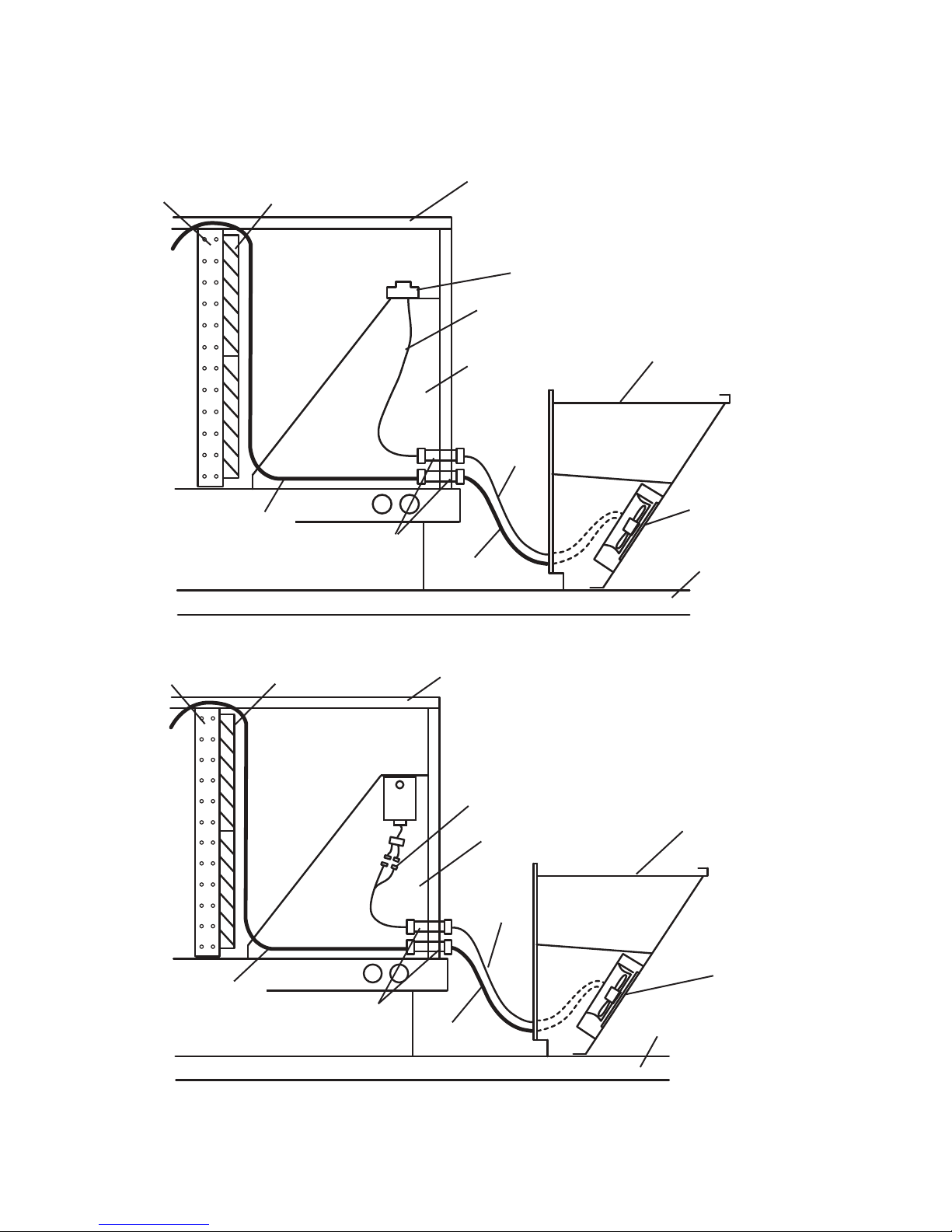
Fig. 4 — Power Exhaust Harness Installation for EconoMi$er IV with W7212 Controller
Fig. 5 — Power Exhaust Harness Installation for EconoMi$er X with W7220 Controller
4
Page 5

FIELD
POWER
SUPPLY
BLK
YEL
BLU
GRN/YEL
To C11 for Small and Large Cabinet
To IFC-11 for Extra-Large Cabinet
To C13 for Small
and Large Cabinet
To IFC13 for
Extra-Large Cabinet
K
BLAC
BLACK
C1
BLUE
EXH.
FAN # 1
GRD.
GREEN-YELLOW
GREEN-YELLOW
C2
BLACK
BLACK
BLUE
EXH.
FAN #2
POWER
EXHAUST
ACCESSORY
GRD.
POWER LINE
PLUG
3
1
2
4
OR
FIELD SUPPLIED
2 X 4 JUNCTION BOX
GROUND
FOR 575V POWER SUPPLY
FOR 208/230V SEPARATE
POWER SUPPLY
3
1
2
4
3
1
2
4
GREEN
BLACK
RED
TO 575V POWER
SECONDARY
D
RE
FIELD
SUPPLIED
FUSED
DISCONNECT
575V
PRIMARY
220V
TRANSFORMER
NO. HT01AH859
(FIELD-SUPPLIED
AND INSTALLED)
BLACK
BROWN
1
4
7
RELAY
3
6
BA
9
BROWN
TAN
GRAY
END
SWITCH
PLUG
1
2
3
4
TO ECONOMI$ER
ACTUATOR
TAN
TAN
1
2
3
GRAY
4
3
E
WHIT
GRAY
BLACK
RED
2
ECONOMI$ER
CONTROLLER
24 VAC
HOT
24 VAC
COM
+
EF
EF1
ECONOMI$ER X
PL-6
123456789101112
BRN
TAN
1
2
3
GRAY
4
ECONOMI$ER IV
2
YEL
Fig. 6 — Power Exhaust Wiring for EconoMi$er IV and EconoMi$er X — 208/230 V and 575 V Units
Field Supplied Wiring
575 V transformer No. HT01AH859 is ordered separately from power exhaust
1
Economizer actuator and controller are shipped with the Economizer -
2
not with power exhaust.
Connections from End Switch plug to Economizer controller are
3
made by installer.
4
If a single power source is to be used, size wire to include
power exhaust MCA and MOCP.
For R-410A units, refer to the unit nameplate for MCA and
MOCP for installed power exhaust.
For R-22 units use the following calculations
Check MCA and MOCP when power exhaust is powered
through the unit. Determine the new MCA including the power
exhaust using the following formula:
MCA New = MCA unit only + MCA of Power Exhaust
For example, using an electric cooling, 6-ton R-22 unit with
MCA = 28.9 and MOCP = 35, with CRPWREXJ030A01 power exhaust.
MCA New = 28.9 amps + 1.5 amps = 30.4 amps
If the new MCA does not go over the MOCP published, then MOCP would
not change. The MOCP in this example is 35 amps, the MCA New is below
35, therefore the MOCP is OK. If “MCA NEW” is larger than the published
MOCP, raise the MOCP to the next larger size. For separate power, the
MOCP for the power exhaust will be 15 amps per NEC.
5
Page 6

1
2
3
4
1
2
3
4
1
2
3
4
1
2
3
4
1
2
3
4
1
2
1
2
3
1
FIELD
To C11 for Small and
Large Cabinet
To IFC-11 for
Extra-Large Cabinet
To C13 for Small
and Large Cabinet
To IFC13
for Extra-Large
Cabinet
POWER
SUPPLY
BLK
YEL
BLU
WHITE
RED
GREEN
OR
FIELD SUPPLIED
2 X 4 JUNCTION BOX
GROUND
FIELD
SUPPLIED
FUSED
DISCONNECT
SEPARATE
POWER
SOURCE
GRN/YEL
EQUIP
GND
POWER
LINE
PLUG
RELAY #1
RELAY #2
123
456
789
AB
123
456
789
AB
GRAY
GRAY
GRAY
GRAY
GRAY
GRAY
POWER
EXHAUST
ACCESSORY
TO ECONOMI$ER
ACTUATOR
END
SWITCH
PLUG
24V
HOT
24V
COM
+
EF EF1
ECONOMI$ER
CONTROLLER
GRAY
GREEN-YELLOW
EXH.
FAN #1
EXH.
FAN #2
GRD
GREEN
BLAC
K
WHITE
BLAC
K
BROWN
BLACK
BLAC
K
BLUE
TA
N
TAN
TAN
WHITE
BLACK
RE
D
BROWN
BLUE
RED
WHITE
BLACK
ECONOMI$ER IV
123456789101112
1
2
3
4
GRAY
TAN
BRN
YEL
ECONOMI$ER X
Field Supplied Wiring
Economizer actuator and controller are shipped
with the Economi$er not with power exhaust
Connection from End Switch Plug to the Economi$er
controller are made by installer
If a single power source is to be used, size wire to include
power exhaust MCA and MOCP.
For R-410A units, refer to the unit nameplate for MCA and
MOCP for installed power exhaust.
For R-22 units use the following calculations
Check MCA and MOCP when power exhaust is powered
through the unit. Determine the new MCA including the power
exhaust using the following formula:
MCA New = MCA unit only + MCA of Power Exhaust
For example, using an electric cooling, 6-ton R-22 unit with
MCA = 28.9 and MOCP = 35, with CRPWREXJ030A01 power exhaust.
MCA New = 28.9 amps + 1.5 amps = 30.4 amps
If the new MCA does not go over the MOCP published, then MOCP would
not change. The MOCP in this example is 35 amps, the MCA New is below
35, therefore the MOCP is OK. If “MCA NEW” is larger than the published
MOCP, raise the MOCP to the next larger size. For separate power, the
MOCP for the power exhaust will be 15 amps per NEC.
PL-6
Fig. 7 — Power Exhaust Wiring for EconoMi$er IV and EconoMi$er X with Controller W7212 — 460 V Units
6
Page 7

Fig. 8 — Power Line Harness Routing (Top View of Unit Shown)
HIGH & LOW VOLTAGE WIRING HARNESS
ECONOMI$ER
Low Voltage Harness
note 1 and 2
FILTER
COIL
INDOOR
FAN
High Voltage
Harness
To RTU
Power Supply
note 2
note 1
RTU CONTROL
BOX
Field supplied
connectors
MAIN POWER
LINE FROM
DISCONNECT
NOTES:
1. The power exhaust comes with a short (24 in. or 36 in.) low voltage extension harness. EconoMi$er 2 includes a longer low voltage harness which is to be used to route back through the unit to the RTU controller in the RTU control box. Use separate knockout for high and
low voltage wires.
2. Low voltage wires with EconoMi$er X attach to wire leads on the EconoMi$er X plug.
3. Ensure main power line, disconnect, and fuse/breaker are sized per National Electric Code.
Power Exhaust Wiring with EconoMi$er and
PremierLink Controller or RTU-MP/OPEN
Use these instructions when installing the vertical power
exhaust with EconoMi$er2 and PremierLink or RTU-MP/
OPEN controller.
1. A low voltage extension harness is supplied with the
EconoMi$er2 (without controller) beginning with unit
serial number 2703Gxxxxx. Prior to serial 2703Gxxxxx,
the supplied low voltage extension harness is not long
enough to reach the PremierLink control board and will
have to be field extended.
The two-wire low voltage harness and the low voltage
extension harness are wire tied together for shipping.
Separate the harnesses for installation and discard the
short low voltage extension harness supplied with power
exhaust.
2. Insert the 2-wire low voltage harness plug from the
power exhaust into the top knockout on the
EconoMi$er2 accessory. (See Fig. 2 and 9.)
3. From the rear of the EconoMi$er2 accessory, connect the
low voltage extension harness plug to the two-wire harness from the power exhaust. (See Fig. 9.)
4. Route the other end of the low voltage extension harness
to the PremierLink controller. (See Fig. 9.)
5. The high voltage harness from the power exhaust and the
high voltage extension harness are plugged together for
shipping. Unplug these 2 harnesses for installation.
6. Insert the high voltage harness plug from the power
exhaust into the bottom knockout on the EconoMi$er2
accessory. (See Fig. 2 and 9.)
7. From the rear of the EconoMi$er2 accessory, connect the
long high voltage extension harness plug to the power
exhaust harness. (See Fig. 9.)
8. Route the other end of the long high voltage extension
harness through the HVAC unit to the control box. (See
Fig. 8.) The harness must be routed through the grommets provided in the unit. Do not drill routing holes. Be
careful not to route the power exhaust harness on top of
the indoor coil.
9. Wire the end of the high voltage harness extension to the
power exhaust power source.
10. Field-Installed PremierLink Control (See Fig. 10): Con-
nect the gray wire from the low voltage extension harness to J8-3 and the tan wire to common terminal.
Common is available from PremierLink terminal J1 or
the common side of the unit control power transformer
(the brown leads that go to unit ground). The other end of
the harness is connected to the power exhaust wiring.
NOTE: When the PremierLink board is configured for a
heat pump, it does not require the HS3/EXH/RVS, allowing this terminal to be used for the power exhaust.
Factory-Installed PremierLink Control: The PremierLink J8-3 terminal is factory wired to a terminal board
TB2-15 (Small and Large Cabinet) or TB3-15 (Extra
Large Cabinet) located in the low voltage section to the
left of the control box. The gray wire from the harness
should be routed and wired to TB2-15 or TB3-15. The
tan wire should be routed and wired to the Central Terminal Board Thermostat Terminal C (Common).
RTU-MP/OPEN Control: Connect the gray wire from
the low voltage harness extension to J11-3 and the tan
wire to the Central Terminal Board Thermostat Terminal
C (Common).
7
Page 8

Fig. 9 — Power Exhaust Harness Installation with EconoMi$er2 and PremierLink Controls
COIL
FILTERS
HVAC UNIT
ECONOMI$ER
ECONOMI$ER/POWER
EXHAUST
OUTDOOR AIR HOOD
2-WIRE
LOW
VOLTAGE
HARNESS
POWER EXHAUST
(INSTALLED POSITION)
ROOF
HIGH
VOLTAGE
HARNESS
KNOCKOUTS
UNIT ROOF CURB
HIGH VOLTAGE
EXTENSION
HARNESS
LOW VOLTAGE EXTENSION HARNESS
TO PERMIERLINK CONTROLLER
PREMIERLINK
TERMINAL
J8
PWR
HS3/EXH/RVS
CU
T FOR DUAL
TRANSFORMER
EQUIPMEN
T
CU
T TO
ISOL
AT
E
CONTROLLE
R
POWER
PWR
RELAYS
J1
J8
RED
ORN
PNK
HS2
HS1
CMP2
CMP1
FAN
WHT
BLU
YEL
R-22 ROOFTOP UNIT
R
DDC CONTROL
RED
RED
GRN
YEL
BLU
RED
WHIT
PNK
RED
ORN
RED
ENTH
NOT USED
SFS
FSD
CMPSAFE
RMTOCC
DISCRETE
J4
Y1
Y2
W1
W2
G
C
X
GRN
BRN
RED
RED
RED
RED
Fig. 10 — Power Exhaust Harness Installation with EconoMi$er2 and PremierLink Controls
8
Page 9

Attaching Power Exhaust to the Unit
UNIT CORNER
POST
GASKETING
POWER
EXHAUST
ECONOMI$ER IV
CONTROLLER
ALUMINUM
FILTER
POWER EXHAUST
5000
4000
3000
2000
1000
0
0
0.1
0.2
0.3
0.4
0.5
EXHAUST
AIRFLOW (cfm)
RETURN DUCT STATIC PRESSURE (in wc)
Small Cabinet
Large and
Extra-Large
Cabinet
1. Make sure all power exhaust harness are connected as
indicated in the previous steps. See Fig. 6 and 7.
2. Make sure all wiring is secure. Use field-supplied wire
ties if necessary. Be sure that wiring does not interfere
with operation of the HVAC unit, economizer, or power
exhaust.
3. For units with a standard filter panel (i.e., no hinged
door): Install the gasketing (provided) on the back of
power exhaust side mating flanges. (See Fig. 11.)
NOTE: This step does not apply to units with a hinged
door.
Fig. 11 — Gasketing Location Detail
(Standard Filter Panel Only)
4. Lift power exhaust and install over economizer using the
3
#10 x
/4 in. long screws provided. Make sure wiring har-
nesses are properly secured. (See Fig. 12.)
Fig. 12 — Power Exhaust Installed on Unit
5. Locate the aluminum filter shipped with the economizer.
Open the filter clips under the top hood of the power
exhaust. Slide aluminum filter into the outside air opening of the power exhaust. Filter will slide past filter clips.
Close filter clips, which will lock filter in place.
6. Reinstall the fan shield.
7. Return power to unit and remove lockout tag.
8. Test power exhaust operation by setting the power
exhaust set point on the economizer controller to 0%.
Power exhaust performance is shown in Fig. 13.
9. Adjust the power exhaust set point on the economizer
controller to the desired activation point per unit schematic.
10. For units with a standard filter access panel, reinstall the
unit filter access door.
For units with a hinged access door (Small and Large
Cabinet), install the hinged door seal angle included in
the power exhaust kit using the instructions in this
instruction. Do not proceed unless the sealing angle is
installed. Units with a hinged door that do not have a
sealing angle may not have a watertight seal.
Fig. 13 — Power Exhaust Performance
9
Page 10

Installing the Hinged Door Angle (Small and
POWER
EXHAUST
SIDE FLANGES
GASKET
LOCATION
(STANDARD
FILTER PANEL
ONLY)
GASKET LOCATION
GASKETED
FLANGE
SEE
NOTE
SEE
NOTE
SEALING
ANGLE
SCREW ANGLE
TO HOOD (3)
A
Large Cabinet)
Follow these instructions if the unit has a hinged panel instead of a standard filter panel. Hinged Door Angle CRPECONV003A00 is for small cabinets and CRPECONV004A00 is for large cabinets.
NOTE: A separate hinged door angle kit must be ordered for the
extra-large cabinet.
1. Find the sealing angle and three screws provided in the
power exhaust kit.
2. Attach the sealing angle to the top of the power exhaust
hood using the screws provided. Refer to Fig. 14 and 15.
Note that the gasketing flange will be facing out.
3. If there are NO pre-drilled holes in the Power Exhaust
hood: Lay the hinged panel, insulation side up, on top of
the hood so that the hinge screw holes align with the predrilled screw holes in the sealing angle. (For hoods with
pre-drilled holes, skip to Step 7.)
4. Check the alignment of the hinged door with the side of
the filter opening to be sure it will close properly.
5. Use a pencil to mark the hood where the screw holes will
be.
6. Remove the hinged door and drill four (4)
where the marks are.
NOTE: The sealing angle will be in place; use the holes
in it as a guide.
7. Place the door and hinges back on the unit. Screw
through the door hinges and sealing angle into the
flanged top of the hood using the 4 screws set aside when
the hinged door was removed. (See Fig. 16.)
8. Close the hinged door and adjust handle if necessary.
11
/64 in. holes
SEALING
NGLE
Fig. 15 — Install Sealing Angle
HINGED DOOR
POWER EXHAUST
HOOD
Fig. 14 — Power Exhaust Installation
Fig. 16 — Install the Hinged Door
PremierLink™ — Operational Notes for Testing
Purposes
If the “continuous power exhaust” function is disabled, the
power exhaust fan will operate during EconoMi$er purge cycles when the EconoMi$er damper position is above the configured minimum value. If enabled, the power exhaust fan
will follow the supply fan's operation for PremierLink version 1.2 and will follow the occupancy configuration for PremierLink version 1.3.
The PremierLink “Auxiliary Output” function defines the
specific use of the auxiliary output (HS3/EXH/RVS) for the
power exhaust. The output will be energized or deenergized
by the appropriate algorithm that uses that specific output.
A setting of 1 = Exhaust fan output.
The Power Exhaust set point in the set point table determines the power exhaust damper “percent open” when the
power exhaust is energized. The damper percentage set point
has a 10% hysteresis.
If “Continuous” in the service configuration table is set to
“enable”, the power exhaust output will energize when occupied (for PremierLink controls version 1.3 and later) and will
be energized when the supply fan relay is on (for versions prior to 1.3).
10
Page 11

Page 12

© Carrier Corporation 2018
Catalog No. 04-53480206-01 Printed in U.S.A. Form IIK-CRPWREXH021-07 Pg 12 8-18 Replaces: IIK-CRPWREXH021-06
Manufacturer reserves the right to discontinue, or change at any time, specifications or designs without notice and without incurring obligations.
 Loading...