

Page 1

°
F
actual temp
set at
mode
fan
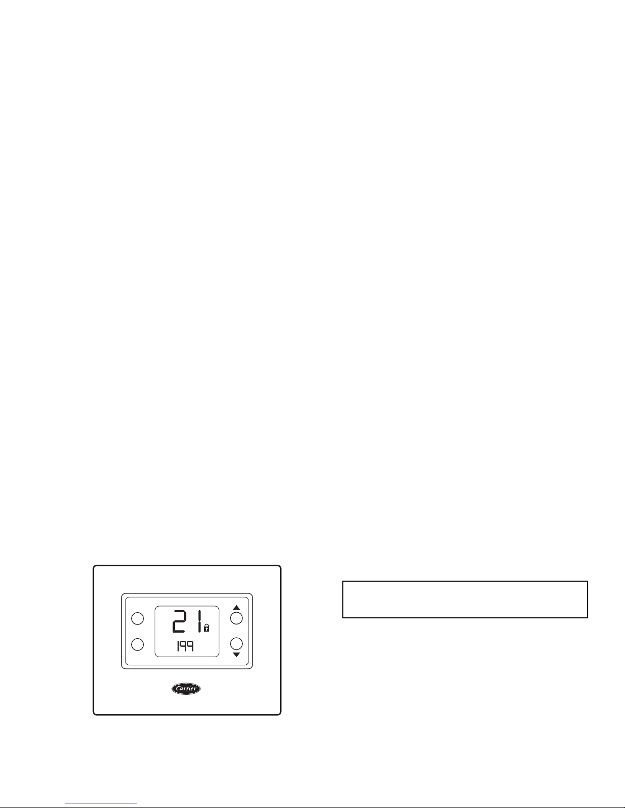
Fig. 1 — Comfort Pro Non-Programmable
Commercial Thermostat
a33-9224
Non-Programmable
Commercial Thermostat
Installation Instructions
Part Number 33CSCNACHP-01
Comfort™ Pro
IMPORTANT: Read entire instruction before installing
the thermostat.
CONTENTS
Page
SAFETY CONSIDERATIONS . . . . . . . . . . . . . . . . . . . . . . 1
GENERAL . . . . . . . . . . . . . . . . . . . . . . . . . . . . . . . . . . . . . . . . 1
PACKAGE CONTENTS . . . . . . . . . . . . . . . . . . . . . . . . . . . 1
INSTALLATION CONSIDERATIONS. . . . . . . . . . . . . .1,2
Power . . . . . . . . . . . . . . . . . . . . . . . . . . . . . . . . . . . . . . . . . . . . 1
Wiring. . . . . . . . . . . . . . . . . . . . . . . . . . . . . . . . . . . . . . . . . . . . 2
Thermostat Location . . . . . . . . . . . . . . . . . . . . . . . . . . . . . 2
INSTALLATION . . . . . . . . . . . . . . . . . . . . . . . . . . . . . . . . . .2,3
CONFIGURATION . . . . . . . . . . . . . . . . . . . . . . . . . . . . . . 3-6
Entering and Exiting Configuration Mode . . . . . . . . 3
Configuration Options . . . . . . . . . . . . . . . . . . . . . . . . . . . 3
Exiting Configuration Mode . . . . . . . . . . . . . . . . . . . . . . 6
SYSTEM START-UP AND CHECKOUT . . . . . . . . . . . . 6
Installer Test Mode . . . . . . . . . . . . . . . . . . . . . . . . . . . . . . . 6
Terminating Installer Test . . . . . . . . . . . . . . . . . . . . . . . . 6
Checklist . . . . . . . . . . . . . . . . . . . . . . . . . . . . . . . . . . . . . . . . . 6
OPERATION. . . . . . . . . . . . . . . . . . . . . . . . . . . . . . . . . . . . .6,7
Mode Selection. . . . . . . . . . . . . . . . . . . . . . . . . . . . . . . . . . . 6
Fan Selection . . . . . . . . . . . . . . . . . . . . . . . . . . . . . . . . . . . . 6
Set Temperature Selection . . . . . . . . . . . . . . . . . . . . . . . 6
Batteries . . . . . . . . . . . . . . . . . . . . . . . . . . . . . . . . . . . . . . . . . 6
Display Lighting. . . . . . . . . . . . . . . . . . . . . . . . . . . . . . . . . . 7
Remote Sensor Temperature Display. . . . . . . . . . . . . 7
Timers . . . . . . . . . . . . . . . . . . . . . . . . . . . . . . . . . . . . . . . . . . . 7
Five-Minute Compressor Timeguard . . . . . . . . . . . . . 7
Minimum On Timer . . . . . . . . . . . . . . . . . . . . . . . . . . . . . . . 7
Cycle Timer . . . . . . . . . . . . . . . . . . . . . . . . . . . . . . . . . . . . . . 7
Staging Timer . . . . . . . . . . . . . . . . . . . . . . . . . . . . . . . . . . . . 7
TROUBLESHOOTING. . . . . . . . . . . . . . . . . . . . . . . . . . . . . 7
Space Temperature Sensor Failure. . . . . . . . . . . . . . . 7
Fan Failure . . . . . . . . . . . . . . . . . . . . . . . . . . . . . . . . . . . . . . . 7
Memory Failure . . . . . . . . . . . . . . . . . . . . . . . . . . . . . . . . . . 7
Equipment Outputs . . . . . . . . . . . . . . . . . . . . . . . . . . . . . . 7
WIRING DIAGRAMS . . . . . . . . . . . . . . . . . . . . . . . . . . . 7-17
THERMOSTAT CONFIGURATION RECORD . . . . CL-1
SAFETY CONSIDERATIONS
Read and follow manufacturer instructions carefully. Follow all local electrical codes during installation. All wiring
must conform to local and national electrical codes. Improper
wiring or installation may damage thermostat.
Recognize safety information. This is the safety alert symbol . When the safety alert symbol is present on equipment
or in the instruction manual, be alert to the potential for personal injury.
Catalog No. 04-53330027-01 Printed in U.S.A. Form 33CS-75SI Pg 1 7-13 Replaces: 33CS-70SI
Manufacturer reserves the right to discontinue, or change at any time, specifications or designs without notice and without incurring obligations.
Understand the signal words DANGER, WARNING, and
CAUTION. These words are used with the safety alert symbol.
DANGER identifies the most serious hazards which will result
in severe personal injury or death. WARNING signifies a hazard which could result in personal injury or death. CAUTION
is used to identify unsafe practices which would result in minor
personal injury or property damage.
GENERAL
Carrier’s Comfort Pro non-programmable thermostats are
wall-mounted, low-voltage thermostats that maintain room
temperature by controlling the operation of a heating and/or air
conditioning system (Fig. 1). This thermostat can be used with
a heat pump, air conditioner or water source heat pump operation. A variety of features are provided including battery operation, separate heating and cooling set points, auto changeover,
keypad lockout, backlighting, and built-in installer test.
This Installation Instruction covers installation, configuration, and start-up of the Comfort Pro non-programmable thermostat. For operational details, consult the Owner's Manual for
this specific thermostat.
PACKAGE CONTENTS
1 — Thermostat
1 — Backplate (mounting base)
2 — Screws and anchors
INSTALLATION CONSIDERATIONS
Power —
one of two ways: full 24 volt AC (50/60 Hz) power via the Rc/
Rh and C terminals or two AA alkaline batteries. The 24 vac
operation is preferred, if available. Battery operation is used
when there are not enough wires to support 24 vac operation.
The thermostat will obtain full operating power
Page 2
When the battery is low, a Low Battery indication will be dis-
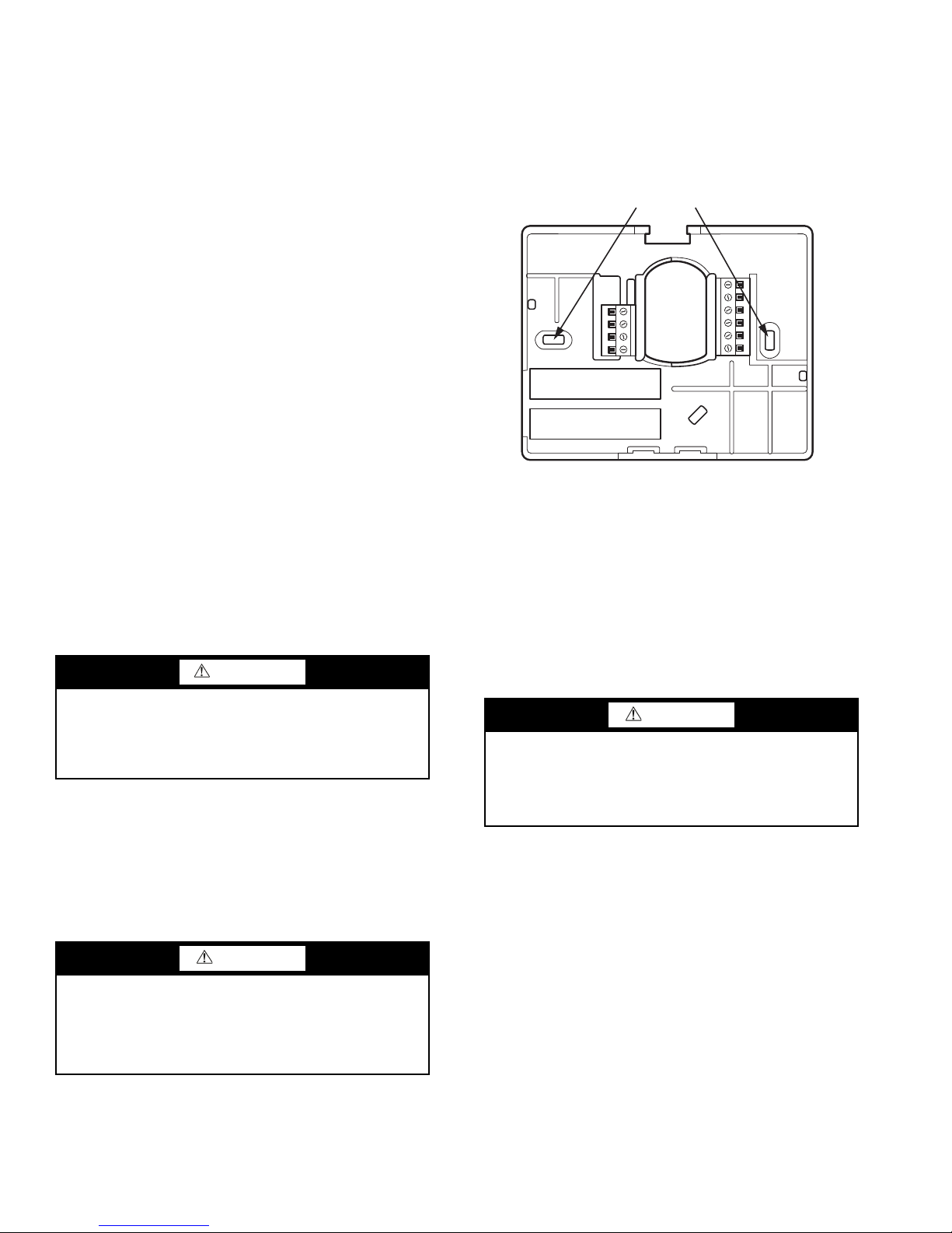
Fig. 2 — Backplate Mounting
a33-9233
played to the user.
For an air conditioning system, up to six wires are needed
for 24 vac operation and one less wire for battery operation.
For a heat pump system, up to seven wires are needed for
24 vac operation and one less wire would be sufficient for battery operation. For heat only operation with batteries, only two
wires are required. When battery operation is used, the C terminal does not need to be connected.
Provision is also made for separate heating and cooling
transformers via separable Rc and Rh terminals which are connected via factory-installed jumper wire.
Wiring — The wire length should be no more than 250 ft
(76 m). Use 22 AWG (American Wire Gage) for normal wiring
applications. Continuous wire lengths over 100 ft (30.5 m)
should use 20 AWG or larger.
Thermostat Location — The thermostat should be
mounted:
• approximately 5 ft (1.5 m) from the floor
• close to or in a frequently used space, preferably on an
inside wall
• on a section of wall without pipes or ductwork
The thermostat should NOT be mounted:
• close to a window, on an outside wall, or next to a door
leading to the outside
• where exposed to direct light and heat or any other tem-
perature-radiating object which may cause a false
reading
• close to or in direct airflow from supply registers or
return air grille in areas with poor air circulation
INSTALLATION
To install the thermostat, perform the following procedure:
1. Turn off all power to equipment.
WARNING
3. Press the thumb release at the top of the thermostat and
snap apart carefully to separate backplate from the thermostat and expose mounting holes.
4. Route thermostat wires through large hole in backplate.
Level backplate against wall (for appearance only, the
thermostat does not need be leveled for proper operation)
and mark wall through two mounting holes. See Fig. 2.
MOUNTING
HOLES
5. Drill two
3
/16-in. mounting holes in the wall where
marked.
6. Secure backplate to wall with two screws and anchors
provided. Make sure all wires extend through hole in
backplate.
7. Adjust length and routing of each wire to reach proper
connector block and terminal on backplate with
1
/4-in.
(6 mm) of extra wire. Strip only 1/4-in. of insulation from
each wire to prevent adjacent wires from shorting together when connected.
Electrical shock can cause personal injury and death.
Before installing thermostat, shut off all power to this
equipment during installation. There may be more than one
power disconnect. Tag all disconnect locations to alert others not to restore power until work is completed.
2. If an existing thermostat is being replaced:
a. Remove existing thermostat from wall.
b. Disconnect wires from existing thermostat, one at
a time. Be careful not to allow wires to fall back
into the wall.
c. As each wire is disconnected, record the wire color
and terminal marking.
d. Discard or recycle old control.
CAUTION
ENVIRONMENTAL HAZARD:
Failure to follow this caution may result in environmental
damage.
Mercury is a hazardous waste. Federal regulations require
that mercury be disposed of properly.
CAUTION
Failure to follow this caution may result in equipment damage or improper operation.
Improper wiring or installation may damage the thermostat. Check to make sure wiring is correct before proceeding with installation or turning on unit.
8. Match and connect equipment wires to proper terminals
of the connector blocks (see Fig. 3). If there are separate
24 vac transformers, one in the indoor unit and one in the
outdoor unit, connect the common of each to the C terminal. Remove factory-installed jumper wire from Rc and
Rh terminals. Connect the R from the indoor unit to the
Rh terminal. Connect the R from the outdoor unit to the
Rc terminal. Then the W signal is taken from the Rh power and the Y1, Y/Y2, G and O/B signals are taken from
the Rc power.
2
Page 3
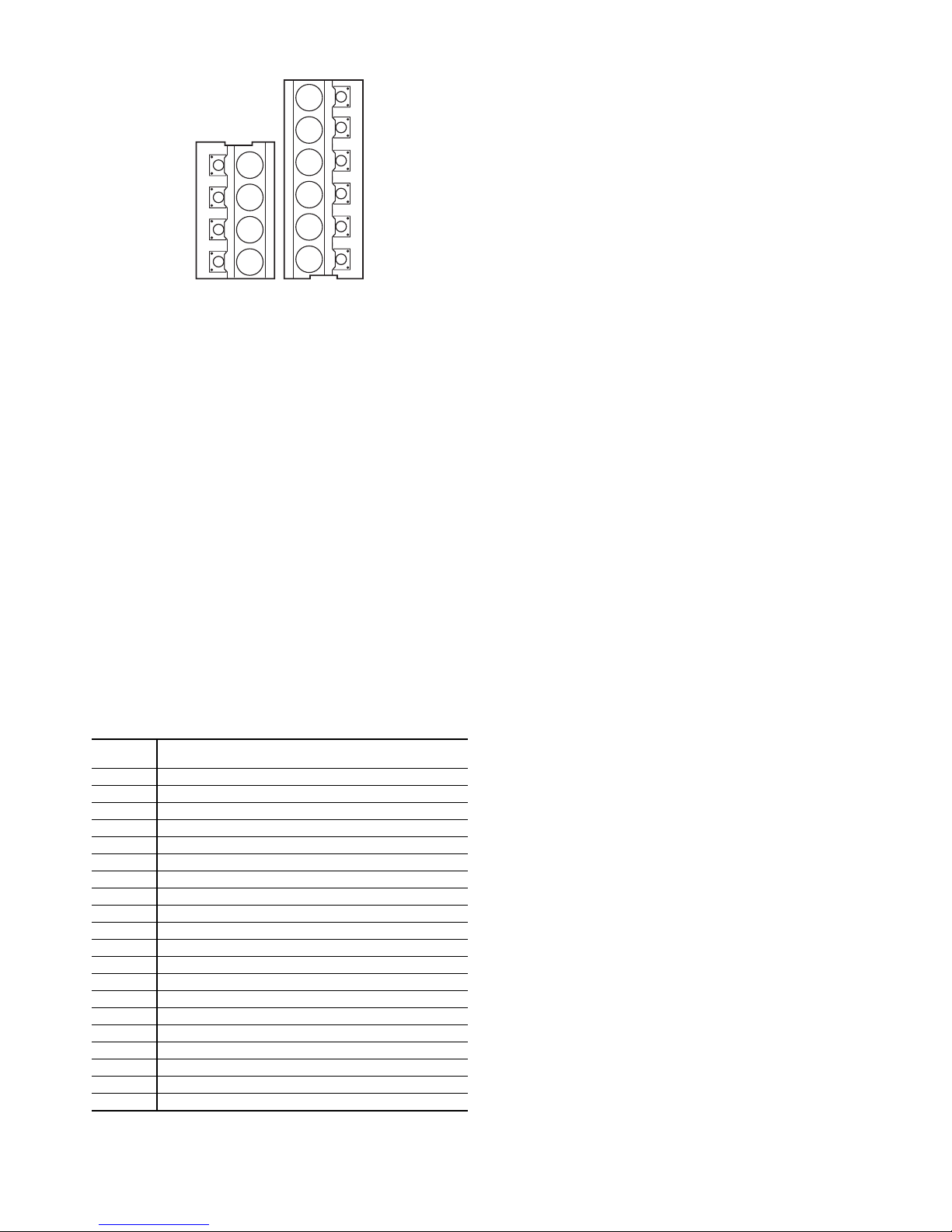
-01
S2
S1
Y1
O/B
Rc
Rh
W
C
G
Y2
Fig. 3 — Terminal Strip
a33-9230
9. Push any excess wire into wall and against backplate.
Seal hole in wall to prevent air leaks. Leaks can affect
operation.
10. Attach thermostat to backplate by inserting tab on bottom
edge and hinging up until top snap secures.
11. Turn ON power to unit.
When power is applied, all display icons are lit for 2 seconds to test the display. Following this, the equipment type for
which the thermostat is configured is displayed for an additional 2 seconds. Equipment type will be either HP, AC, H, C or 35
(for WSHP) (for explanation see Option 01 below).
NOTE: If a common wire has not been connected, two AA
batteries must be used to power the thermostat.
CONFIGURATION
Configuration options enable the installer to configure the
thermostat for a particular installation. These configuration options are stored to the internal memory so they are retained
through a power outage. The availability of some configuration
options will be dependent upon other conditions in the thermostat. For example, the backlight configuration is not available
unless full 24 vac power is connected. See Table 1.
Table 1 — Configuration Options Summary
OPTION
NUMBER
01 Equipment Type
02 Remote Sensor Selection
03* English/Metric
04 Fan (G) on with W Output
05 Space Temperature Sensing
07 Equipment DDC Controller
10 Reversing Valve
11 Deadband between Heating and Cooling Set Points
13 Space Temperature Display Adjustment (Offset)
15 Auto Mode Availability
16 Maximum Cycles Per Hour
17 Time Between Equipment Stages
18* Backlight Configuration
20 Outdoor Air Temperature Adjustment (Offset)
21 Keypad Lockout
26 Minimum Cooling Set Point
27 Maximum Heating Set Point
35 Emergency Heat Mode Availability
39 Temperature Display
99 Reset to Factory Defaults
* These settings are adjustable by the user. See Owner’s Manual for
additional information.
CONFIGURATION
Entering and Exiting Configuration Mode —
Press and hold the fan button for about 10 seconds. After the
10-second period the Option number "01" will appear flashing
in the space temperature location. The value of the configuration setting will be displayed in the set point location.
The parameter that is changeable will be determined by the
flashing area. The up or down button can be used to select a
new value. The mode button can be used to toggle/move the
selection between the configuration option number and the
configuration value. To exit the installer configuration screen,
press the fan button. If no button is pressed for three minutes,
the installer configuration screen will time out and the thermostat will return to normal operation.
All changes to the installer configuration are saved as they
are made. There is no provision to exit the installer configuration and cancel the change. The installer will have to manually
change a configuration back to its original value to "undo" a
change.
Configuration Options
OPTION 01 — EQUIPMENT TYPE — This option determines the control method of the thermostat. It should match the
type of equipment used.
Selection: HP, AC, H, C, 35
HP — operates a two-stage heat pump
AC — operates a two-stage AC with single unit
H — operates a heat only system
C — operates a cool only system
35 — operates a water source heat pump
Default: AC
OPTION 02 — REMOTE SENSOR SELECTION — A re-
mote thermistor can be connected to the S1 and S2 screw terminals to sense either remote space, outdoor air, supply or return air temperature.
NOTE: Carrier sensors 33ZCT55SPT, 33ZCSENDAT,
33ZCSENSAT, and 33ZCSENOAT may be used for standard
space temperature sensor averaging. Sensors must be used as a
single sensor, 4 sensors or 9 sensors, with total sensor wiring
not to exceed 1,000 ft.
Selection: rS, SA, Od, rA
rS — Sense remote space temperature
SA*— Sense supply air temperature
Od*— Sense outdoor air temperature
rA* — Sense return air temperature
* Display only, not used for temperature control.
Default: Od
OPTION 03 — ENGLISH/METRIC — This configuration
selects between Fahrenheit (F) and Celsius (C) operation.
Selection: F, C
Default: F
OPTION 04 — FAN (G) ON WITH W OUTPUT — This
configuration is not available if the thermostat is configured as
Cool Only in Option 01. This selection determines whether fan
(G) output is to be on or off when the W is energized in AC,
HP, H or 35 (WSHP) configurations, and when the O/B output
is energized in the AC or H (heat only) configurations.
Selection: OF(F), ON
OF — Fan does not turn on with W output
ON — Fan turns on with W output
Default: ON
OPTION 05 — SPACE TEMPERATURE SENSING —
This selection determines which sensor the control will use for
measuring space temperature. Space temperature can be
3
Page 4

sensed in one of three ways: the local sensor (L) located on the
thermostat, the remote sensor (r), or the average of local and
remote sensors (Lr).
Selection: L, r, Lr
L — Local sensor: The onboard thermistor is the control
point for the temperature control algorithm.
r — Remote space sensor: The remote space temperature
is the control point for the temperature control algorithm.
NOTE: This selection is only available if Option 02 indi-
cates that the S1, S2 terminals are sensing a remote space
temperature.
Lr — Average (remote space sensor and space temperature): The average of the onboard thermistor and the
remote space sensor is the control point for the temperature control algorithm.
NOTE: This selection is only available if Option 02 indicates that the S1, S2 terminals are sensing a remote space
temperature.
Default: L
OPTION 07 — EQUIPMENT DDC CONTROLLER —
This selection should be set to ON when control is to be used
with DDC (direct digital controller) equipment. These control
systems will take care of the time guard and cycle timers.
Examples are zone controlling units or two-position valve
assemblies that can open or close as required, without regard to
exceeding a maximum number of operations per hour. Rooftop
units used with PremierLink™ or ComfortLink controls do not
require thermostat control to handle timers and safeties, so this
selection would also be set to ON in this case.
Set this selection to OF (off) if the thermostat is directly
connected to equipment such as a furnace or fan coil unit with
DX condensing units, or electro-mechanical rooftop units that
have a maximum number of cycles per hour rating, but do not
implement that requirement themselves and rely instead on the
thermostat.
Selection: OF(F), ON
OF — Timeguard and cycle timers are enabled
ON — Timeguard and cycle timers are disabled
Default: OF (off)
OPTION 10 — REVERSING VALVE — This feature is
only available on heat pump (HP) systems. Although the water
source heat pump is also a heat pump system, a WSHP system
will always energize the reversing valve in cooling and therefore, this option is not available to the installer on either 35 or
WSHP systems.
The "O/B" terminal can be configured to be energized in either heating mode or in cooling mode, depending on heat pump
operation. The "C" configuration is used to describe a heat
pump system that energizes its reversing valve in cooling. The
"H" configuration is used to describe a heat pump system that
energizes its reversing valve in heating.
Selection: H, C
H — The reversing value output (O/B) is energized when
HEAT mode is selected.
C — The reversing value output (O/B) is energized when
COOL mode is selected.
Default: H
OPTION 11 — DEADBAND BETWEEN HEATING AND
COOLING SET POINTS — The selection allows the installer to choose how much differential will exist between the heating and cooling set points.
Selection: 1 to 10 (F or C)
Default: 5
OPTION 13 — SPACE TEMPERATURE DISPLAY
ADJUSTMENT (OFFSET) — This configuration is the
number of degrees to be added to the displayed temperature to
calibrate or deliberately miscalibrate the measured space tem-
perature. This selection is not available to the installer if Option
39 is set to SP (setpoint display).
Selection: –5 to 5 F (always in F)
Default: 0
OPTION 15 — AUTO MODE AVAILABILITY — The
ON selection will allow automatic changeover between heating
and cooling as demand requires a mode selection. OF
maintains either heating or cooling mode selection only. Auto
changeover is not available when H or C is selected under Option 01.
Selection: ON, OF(F)
ON — Auto mode is an available option that can be
selected
OF — Auto mode is not an available option
Default: ON
OPTION 16 — MAX CYCLES PER HOUR — The maximum cycle rate is limited by internal timers to the selected
number of cycles per hour. Selection of a higher number causes
faster cycling resulting in more constant room temperature.
Selection: 4, 6, 8
4 — The Y1 and W outputs will be energized at most
twice per hour. When an output is energized, it will not
be energized again for 15 minutes.
6 — The Y1 and W outputs will be energized at most
four times per hour. When an output is energized, it will
not be energized again for 10 minutes.
8 — The Y1 and W outputs will be energized at most six
times per hour. When an output is energized, it will not
be energized again for 8 minutes.
Default: 4
OPTION 17 — TIME BETWEEN EQUIPMENT
STAGES — This configuration determines the minimum
number of minutes of equipment operation before allowing the
transition to the next logical stage.
Selection: 10, 15, 20, 25
Default: 15
NOTE: If the difference between the space air temperature and
set point results in a demand greater than three degrees, then
the staging timers are ignored and the equipment will stage up
in 60-second increments.
OPTION 18 — BACKLIGHT CONFIGURATION — This
function is only available when the thermostat is operating
from 24 volt AC power connected to the R and C terminals. It
is not available when the thermostat operates from batteries.
When set to OF (off), the backlight will be lit for 10 seconds
after a button is pressed. After 10 seconds of no button presses,
the backlight turns off.
When ON is enabled, the backlight will normally be on and
dim in appearance. The backlight brightness becomes brighter
when a button is pressed. After 10 seconds of no button presses, the backlight will return to the dimmer level until another
button press occurs.
Selection: OF(F), ON
Default: ON with 24 vac power; for batteries only,
default is OFF.
OPTION 20 — OUTDOOR AIR TEMPERATURE DIS-
PLAY ADJUSTMENT (OFFSET) — This selection is not
available unless Option 02 is set to Od (outdoor air temperature) and a valid sensor is connected to S1 and S2 terminals. It
allows the calibration, or deliberate miscalibration of the outdoor air temperature sensor reading.
4
Page 5
Selection: –5 to 5 (number of degrees F added to the out-
Fig. 4 — Selection of Code Value
a33-9225
door air temperature reading to "calibrate" the temperature sensor)
Default: 0
OPTION 21 — KEYPAD LOCKOUT WITH PASSCODE — The thermostats are shipped with the keypad fully
accessible. This option allows the installer to limit access to the
keypad.
Selection: OF(F), 1, cd
OF — When set to OF, the user has full access to the key-
pad
1 — The user will only have access to modify the set points
(within the set point limits of Option 26 and Option 27). The
padlock icon will be displayed until the user presses and
holds the up and down buttons simultaneously for five
seconds to unlock the keypad. Once the keypad is unlocked,
the user has full access to the thermostat functionality. The
keypad returns to the locked condition after no buttons have
been pressed for two minutes.
cd — The entire keypad is locked and the padlock icon is
displayed. When the user presses a button the backlight
turns on to maximum brightness for 10 seconds and a "--" is
displayed in the temperature setting. The user must enter the
unlock code and press the mode button to unlock the thermostat. The padlock icon will then turn off and the user will
have full access to the thermostat functionality. The thermostat will lock after no buttons have been pressed for two
minutes.
If the option value is set to "cd," the mode, up and down
buttons will work as follows:
1. Pressing the mode button once will display the flashing
Option number (21).
2. Pressing the mode button again and the option value
will flash OF, 1 or cd.
3. Pressing the mode button a third time will display the
keypad lock icon and the code entry values (see Fig. 4).
The up and down buttons will allow the selection of a
code value between 00 to 199.
4. Pressing the mode key again will return the focus to the
Option number (21).
In the event that the installer or user cannot remember the
unlock code for the thermostat, the code can be displayed if the
user presses and holds the fan and the down buttons simultaneously for 30 seconds. After the 30-second period, the unlock
code will be displayed for five seconds. This information does
not appear in any other user documentation.
Default: OF (off)
OPTION 26 — MINIMUM COOLING SET POINT —
This parameter establishes the minimum cooling set point that
the user is allowed to set. If the equipment type is Cool Only,
the lower limit is 55 F and the upper limit is 90 F. Otherwise,
the equipment type allows both heating and cooling operation,
so the minimum is 55 F plus Option 11 (deadband) and the
maximum is 90 F.
Selection: minimum = 55 F + deadband, maximum = 90 F
Default: 60 F (based on the adjustable deadband default = 5)
OPTION 27 — MAXIMUM HEATING SET POINT —
This parameter establishes the maximum heating set point that
the user is allowed to set. If the equipment type is Heat Only,
the lower limit is 50 F and the upper limit is 90 F. Otherwise,
the equipment type allows both heating and cooling operations, so the minimum is 50 F plus Option 11 (deadband) and
the maximum is 90 F.
Selection: minimum = 50 F, maximum = 90 F – deadband
Default: 85 F (based on adjustable deadband default = 5)
OPTION 35 — EMERGENCY HEAT MODE AVAILABILITY — This configuration allows the installer to turn on
or off the Emheat (emergency heat) mode. When set to ON, the
Emergency Heat mode is an available m
ode selection. When
set to OF, the Emergency Heat mode is not an available mode
selection. Not available if Option 01 is set to C (cool only).
Selection: OF(F), ON
Default: OF (off)
OPTION 39 — TEMPERATURE DISPLAY — This configuration allows the installer to select either the set point temperature or the space temperature to be displayed on the large
temperature display digits.
When the option St is chosen, the space temperature, as defined by Option 05, is displayed using the traditional space
temperature digits on the LCD display. The current set temperature is displayed using the normal set point display digits.
When SP is chosen, the current set point temperature is displayed using the traditional space temperature digits on the
LCD display. The normal set point display digits remain blank.
Space temperature is not displayed, but if a problem occurs
with the actual space temperature sensor, the characters "- -"
will be displayed instead of the Set temperature to indicate that
the temperature sensor has an error.
NOTE: The "Actual Temp" icon is not be displayed when the
sensor type is set to set point display (SP).
Selection: St, SP
Default: St (Space Temperature)
OPTION 99 — RESET TO FACTORY DEFAULTS —
This configuration allows the installer to return the thermostat
to its "out of the box" settings.
mode
fan
IMPORTANT: All configuration options, mode, fan and
set point settings which have been manually entered will be
lost and reset.
When this setting is first selected, 99 will be displayed in the
space temperature location and an initial value of 10 will be
displayed in the set point location.
To initiate factory defaults, the installer then presses the
mode button until the 10 is flashing. The installer then presses
and holds the down button. While the down button is held, the
10 will count down from 10 to zero at a rate of 2 counts per
second (5 seconds total). When the value reaches zero, all display segments are turned on for five seconds and the factory
defaults are restored. If at any time during the countdown the
installer releases the down button, the countdown terminates
and the display returns to the starting value of 10.
5
Page 6
Exiting Configuration Mode — To exit the configu-
mode
fan
heat
auto
fan
aux heat
on
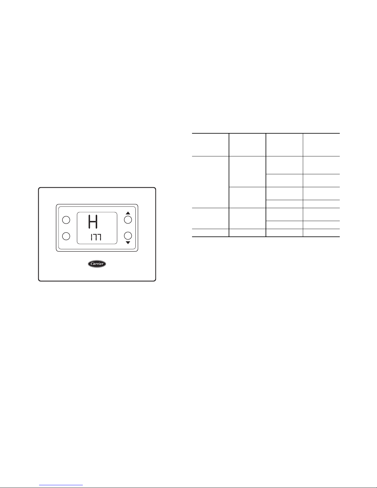
Fig. 5 — Installer Test Mode
a33-9226
ration mode, press the fan button.
SYSTEM START-UP AND CHECKOUT
Installer Test Mode —
staller test capability. It allows easy operation of equipment
without delays or set point adjustments to force heating or
cooling. To enter installer test mode, press and hold the fan
button for 15 seconds (after 10 seconds installer configuration
is entered; a continuous 15 seconds and installer test is
entered). At the start of installer test, the mode is Off, the fan is
"fan auto" and the set point displays “InS.”
The mode button is used to change the system operating
mode to test the heating and cooling equipment. Auto mode is
not available during installer test.
When the mode is set to heat, heating is energized for
180 seconds. During the installer test operation, the "on" icon is
displayed.
At the end of the equipment test cycle the mode returns to
OFF.
The LCD display counts down the time remaining (in seconds, from 180 to 0) for each stage when the equipment is energized. See Fig. 5.
This thermostat has a built-in in-
in its normal operating mode, consult the Owner's
Manual.
2. If the equipment is to be left in operation, the set points
and operating mode must be properly selected.
3. Put away tools and instruments and clean up debris.
4. Review and leave Owner's Manual with customer.
OPERATION
Mode Selection —
display the off, heat, cool, auto and emergency heat icons.
Pressing the mode button cycles through the available modes
based on the equipment selection from Option 01, the auto
availability setting from Option 15, and the electric heat availability from Option 35. Available choices are listed in Table 2.
Table 2 — Mode Selection
OPTION 01
(Equipment
Selection)
AC, HP or
35 (WSHP)
H Not Available
C Not Available Not Available Off, Cool
OPTION 15
The mode button allows the user to
OPTION 35
(Auto
Available)
On
Off
(Emergency
Heat Mode
Available)
On
Off
On
Off Off, Heat, Cool
On
Off Off, Heat
AVAILABLE
MODES
Off, Heat,
Cool, Auto,
Em Heat
Off, Heat,
Cool, Auto
Off, Heat,
Cool, Em Heat
Off, Heat,
Em Heat
The same procedure is repeated for the cool mode. "C" is
displayed when cooling is active.
The test of a heating or cooling cycle can be terminated before the timer counts down to zero by pressing the mode
button.
Pressing the fan button alternates the fan selection between
fan auto and fan on and the fan output follows accordingly.
There is no timer associated with the installer testing of the fan
operation.
Setting the mode to Em heat, if available, turns on the auxiliary heat for 180 seconds. The space temperature location displays an "E," the clock display counts down from 180 to 0 in
one-second increments and the "aux heat on" icon is displayed.
At the end of the 180 seconds, the mode returns to OFF.
Terminating Installer Test — After 15 minutes of no
button presses by the installer, installer test is terminated.
Pressing the up button, down button, or cycling thermostat
power at any time during installer test terminates the installer
test and returns the thermostat to normal operation.
Checklist — The following installer checklist should be
performed after completing installation:
1. Run equipment through several heating and cooling cycles to ensure proper operation. To operate the thermostat
Fan Selection — Pressing the fan button toggles between
the Fan On and Fan Auto selections. When the “fan on” icon is
displayed, the fan operates continuously. When “fan auto” is
displayed, the fan will run only with the equipment.
Set Temperature Selection — If auto mode is not ac-
tive and off mode is not active, pressing the up or down button
causes the set point corresponding to the current system mode
to be updated. If the up or down button is held, the set point
value will be scrolled. The set point change also takes into account that Option 11 (deadband) is preserved along with ensuring that Option 26 (minimum cooling set point) and Option 27
(maximum heating set point) are taken into account to enforce
set point limits.
If auto mode is active, pressing the up or down button
causes the set point corresponding to the current operating
mode to be updated. To move between the heat and cool set
points, press the mode button to toggle between set points.
Once the desired set point has been adjusted, press the mode
button to return to auto mode.
If off mode is active, the up and down buttons are ignored
for changing set point(s).
When changing the set points, the following restrictions are
in place. The cool set point cannot be increased above 90 degrees F (32 C) or decreased below Option 26, the minimum
cooling set point. The heat set point cannot be decreased below
50 F (10 C) or increased above Option 27, the maximum heating set point.
When Option 39 is set to SP (set point), the set point adjustment is displayed in the large space temperature digits.
Batteries — Battery operation is available for installations
where there is no common (C) wire available at the thermostat.
For battery operation, install two alkaline AA batteries. The
6
Page 7

thermostat is designed to operate up to one year on a set of batteries. A battery indicator on the display warns when battery replacement is needed. If batteries are installed and the thermostat is operating from 24 vac power, battery operation will occur only when 24 vac power is not present. The changeover
between 24 vac power and battery power is automatic.
Display Lighting — The display has two levels of light-
ing, high level and low level. High level lighting comes on for
10 seconds when buttons are being pressed with 24 vac and
with batteries. Low level lighting is only available if the thermostat is operated from 24 vac; it is not available with batteries. The low level can be selected (see Option 18) for continuous backlight.
Remote Sensor Temperature Display — Press-
ing the up and down buttons simultaneously displays the temperature of the sensor connected to the S1 and S2 terminals for
five seconds, then the thermostat returns to normal operation.
If the sensor is invalid, then the display shows "--" in the
large temperature display digits.
NOTE: Carrier sensors 33ZCT55SPT, 33ZCSENDAT,
33ZCSENSAT, and 33ZCSENOAT may be used for standard
space temperature sensor averaging. Sensors must be used as a
single sensor, 4 sensors or 9 sensors, with total sensor wiring
not to exceed 1,000 ft.
The remote space temperature 33ZCT55SPT sensor includes a button that, when pressed, shorts the S1 and S2 terminals. If the thermostat is powered by 24 vac and Option 02 is
set to rS, pressing the button for two to five seconds has the
same effect as an occupied button press on the thermostat. This
button press is only recognized when the thermostat is powered
by 24 vac.
Timers — Several timers that influence the thermostat’s op-
eration are listed below. If any of the timers is preventing the
equipment from turning on, the "on" icon will flash.
Five-Minute Compressor Timeguard — This tim-
er prevents the Y1 output from turning on unless it has been off
for 5 minutes.
After a power cycle, a randomized delay will be added to
end of the timeguard timer to prevent multiple units from hitting the power grid all at the same time. The randomization
timer will be between zero and five minutes. If a demand exists, compressor outputs will energize between 5 and 10 minutes after the power cycle. It can be defeated by simultaneously
pressing the fan and up keys.
Minimum On Timer — Once the equipment has been
turned on, it must remain on for 3 minutes. A change in mode
or set point will cancel this timer.
Cycle Timer — The number of equipment cycles per hour
is determined by configuration Option 16. Based on the selection of 4, 6 or 8 cycles per hour, this timer is set to 15, 10 or
8 minutes. This much time must elapse from the start of one
cycle before another cycle can start, imposing the cycles per
hour limits. It can be defeated for one cycle by simultaneously
pressing the fan and up keys.
Staging Timer — The staging timer enforces a minimum
number of minutes for the current stage of equipment capacity
to be energized before staging up to the next level of capacity.
The number of minutes between each stage is configured by
the installer in software configuration Option 17.
TROUBLESHOOTING
Three system error messages may appear on the thermostat
screen indicating a problem with the thermostat’s operation.
See below for possible system error messages and their
meaning.
Space Temperature Sensor Failure — If the
room temperature sensor fails, the temperature display will
show “--” (two dashes). If the space temperature is the average
of both the local and remote sensors (as configured in Option
5), and one of the sensors fails, the thermostat provides control
to the valid sensor only. The display will alternate every 10 seconds between "--" for the invalid sensor and the reading from
the valid sensor.
Fan Failure — The fan setting is specified by Option 36
and cannot be changed by the user. If Option 36 is set to ON,
and the fan button is pressed, an E7 error message will be displayed for three seconds and the fan selection will remain ON
and not be changed.
Memory Failure — If there is an internal memory failure,
the temperature display will show “E4,” and the thermostat
needs to be replaced.
Equipment Outputs — Table 3 can be used as a trou-
bleshooting tool for determining which outputs will be active
for a particular configuration and each operating mode.
Table 3 — Equipment Outputs
EQUIP
CONFIG
(Option
01
Setting)
AC Y1
HP
Option
10=C
HP
Option
10=H
WSHP
COOL
STAGE
H ——W
C Y1
1
Y1,
O/B
Y1
Y1,
O/B
COOL
STAGE
2
Y1,
Y2
Y1,
Y2,
O/B
Y1,
Y2
Y1,
Y2
Y1,
Y2,
O/B
HEAT
STAGE
STAGE
1
W
Y1
Y1,
O/B
————
Y1
HEAT
2
W,
O/B
Y1,
Y2
Y1,
Y2,
O/B
W,
O/B
Y1,
Y2
HEAT
STAGE
—O/B
Y1,
Y2,
W
Y1,
Y2,
W,
O/B
—O/B
Y1,
Y2,
W
EM
HEAT
3
W
W
W
WIRING DIAGRAMS
System wiring diagrams are provided for typical Carrier
equipment. See Fig. 6-24.
7
Page 8

33CSCNACHP-01
Rc
Rh
W
C
G
Y2
S1
S2
O/B
Y1
6 24 VAC
7 COMMON
8 FAN
Fig. 6 — Thermostat Wiring — 42B Motor Controls — Single-Phase Only, 3-Phase Only, Single-Phase with
Interlocking Disconnect, and 3-Phase with Interlocking Disconnect
a33-9243
33CSCNACHP-01
Rc
Rh
W
C
G
Y2
S1
S2
O/B
Y1
6 24 VAC
7 COMMON
8 FAN
4 HEAT 1
Fig. 7 — Thermostat Wiring — 42B Motor Controls — Single-Phase and 3-Phase
with Interlocking Disconnect and Single-Stage Electric Heater
a33-9244
8
Page 9

33CSCNACHP-01
Rc
Rh
W
C
G
Y2
S1
S2
O/B
Y1
6 24 VAC
7 COMMON
8 FAN
4 HEAT 1
3 HEAT 2
Fig. 8 — Thermostat Wiring — 42B Motor Controls — 3-Phase with Interlocking Disconnect
and 2-Stage Electric Heater
a33-9245
33CSCNACHP-01
Rc
Rh
W
C
G
Y2
S1
S2
O/B
Y1
X*
C
G
W2
W1
Y2
Y1
R
Unit CTB Thermostat
Fig. 9 — Thermostat Wiring — 48/50HC, 48/50TC, and 48/50LC04-06 Rooftop Units
a33-9246
* X is not wired to thermostat.
9
Page 10

33CSCNACHP-01
Rc
Rh
W
C
G
Y2
S1
S2
O/B
Y1
R
W1
W2
C
Y1
Y2
G
TB3
Fig. 10 — Thermostat Wiring — 50EJQ,EWQ024,028 Heat Pump Units
a33-9247
33CSCNACHP-01
Rc
Rh
W
C
G
Y2
S1
S2
O/B
Y1
R
G
Y1
Y2
W1
W2
C
X*
Fig. 11 — Thermostat Wiring — 50HJQ004-016 Units
* X is not wired to thermostat.
a33-9248
10
Page 11

33CSCNACHP-01
Fig. 12 — Thermostat Wiring — 50HQL, KQE, KQL, P1, PC, PEC, PS, PSW, PT, RHC, RHE,
RHR, RHS, RTG, RVC, RVE, RVR, RVS, RWS, VQL Water Source Heat Pump Units with
Complete C Controls and Duct Heating Option
a33-9309
Y1
Y2
W1
O/W2
G
R
C
AL1
DELUXE D
P1
CONFIGURE AS
OPTION 1 = HP
33CSCNACHP-01
Rc
Rh
W
C
G
Y2
S1
S2
O/B
Y1
Fig. 13 — Thermostat Wiring — 50HQL, KQE, KQL, P1, PC, PEC, PS, PSW, PT, RHC, RHE, RHR, RHS, RTG,
RVC, RVE, RVR, RVS, RWS, VQL Water Source Heat Pump Units with Deluxe D Controls
a33-9310
Rc
Rh
W
C
G
Y2
S1
S2
O/B
Y1
INSTALL JUMPER G TO QT
COMPLETE C
P1
Y
DUCT HEATER
G
R
QT
C
W1
W2
W3
W4
COMPLETE C
P1
Y
W
O
G
R
C
AL1
SECOND
COMPRESSOR
FIRST
COMPRESSOR
11
Page 12

33CSCNACHP-01
Rc
Rh
W
C
G
Y2
S1
S2
O/B
Y1
COMPLETE C
P1
Y
W
O
G
R
C
AL1
FIRST
COMPRESSOR
Fig. 14 — Thermostat Wiring — 50HQL, KQE, KQL, P1, PC, PEC, PS, PSW, PT, RHC, RHE, RHR, RHS, RTG,
RVC, RVE, RVR, RVS, RWS,VQL Water Source Heat Pump Units with Complete C Controls
a33-9302
33CSCNACHP-01
Rc
Rh
W
C
G
Y2
S1
S2
O/B
Y1
R
C
Y1
Y2
O
G
Fig. 15 — Thermostat Wiring — 50VS Water Source Heat Pump Units
a33-9251
12
Page 13

X*
C
G
W1
Y2
Y1
R
33CSCNACHP-01
TERMINAL BOARD
W2†
Rc
Rh
W
C
G
Y2
S1
S2
O/B
Y1
Fig. 16 — Thermostat Wiring — 50HCQ,TCQ Rooftop Units
*Connection not required.
†W2 connection not required on units without electric heating.
a33-9308
33CSCNACHP-01
*Connection not required.
Fig. 17 — Thermostat Wiring — 50HJQ014,016 Heat Pump Units
a33-9307
Rc
Rh
W
C
G
Y2
S1
S2
O/B
Y1
13
R
G
Y1
Y2
W1
W2
C
IPD/X*
Page 14

33CSCNACHP-01
R
Y1
Y2
W1
W2
G
C
X*/8
38ARD007-02
LLSV-1
IFC
CONNECTION
BOARD (TB)
LLSV-2
1
2
3
W1
W2
4
9
5
38ARD014-024
TB2
Rc
Rh
W
C
G
Y2
S1
S2
O/B
Y1
Fig. 18 — Thermostat Wiring — 38ARD Commerical Split System Units
*Connection not required.
LEGEND
IFC — Indoor Fan Contactor
LLSV — Liquid Line Solenoid Valve
a33-9304
FAN COIL
40RMQ SERIES
CONDENSING UNIT
38ARQ SERIES
G
C
R
C
INDOOR UNIT
OUTDOOR UNIT
W2
Y2
Y1
W2
33CSCNACHP-01
Rc
Rh
W
C
G
Y2
S1
S2
O/B
Y1
a33-9305
Fig. 19 — Thermostat Wiring — 38ARQ008-012 Series and 40RMQ008-012 Series Split System Units
14
Page 15

33CSCNACHP-01
Fig. 20 — Thermostat Wiring — 38AU Commercial Split System Units with 40RUA Air Handler Units
a33-9303
Fig. 21 — Thermostat Wiring — 40RU/38RU Packaged Air-Handler Units
a33-9306
INDOOR
CONNECTION
BOARD (TB)
OUTDOOR
CONNECTION
BOARD (TB)
Rc
Rh
W
C
G
Y2
S1
S2
O/B
Y1
R
Y1
Y2
W1
W2
G
C
ONLY REQUIRED FOR
38AUQ HEAT PUMP
R
Y1
Y2
W1
W2
G
C
TERMINAL BLOCK
JUMPER FOR
HEAT PUMP
WIRING
TB1
ELECTRIC HEAT
ACCESSORY
OMIT FOR
HEAT PUMP
WIRING
33CSCNACHP-01
THERMOSTAT TERMINAL STRIP
Rc
Rh
W
C
G
Y2
S1
S2
O/B
Y1
CONNECT TO
24VAC AT
CONDENSING
UNIT
15
Page 16

OAT SENSOR
REMOTE
ROOM
33CSCNACHP-01
SENSOR
Rc
Rh
W
C
G
Y2
S1
S2
O/B
Y1
Fig. 22 — Thermostat Wiring — Outdoor Air Temperature and Remote Room Temperature Sensors
a33-9323
SENSOR 1 SENSOR 2
SENSOR 3
SENSOR 4
33CSCNACHP-01
RRS
STRN
Fig. 23 — Thermostat Wiring — Space Temperature Sensor Averaging Wiring ( 4 Sensor Application)
a33-9324
16
Page 17

SENSOR 4
SENSOR 8SENSOR 7
SENSOR 5
SENSOR 9
SENSOR 6
SENSOR 1 SENSOR 2 SENSOR 3
33CSCNACHP-01
RRS
STRN
Fig. 24 — Thermostat Wiring — Space Temperature Sensor Averaging Wiring (9 Sensor Application)
a33-9325
17
Page 18

© Carrier Corporation 2013
Manufacturer reserves the right to discontinue, or change at any time, specifications or designs without notice and without incurring obligations.
Catalog No. 04-53330027-01 Printed in U.S.A. Form 33CS-75SI Pg 18 7-13 Replaces: 33CS-70SI
Page 19

Page 20

THERMOSTAT CONFIGURATION RECORD
INSTALLER
________________________________________________
PART NUMBER
________________________________________________
DATE
________________________________________________
HOLE IN WALL SEALED _________________________
MODE SETTINGS
MODE (Off, Heat, Cool, Auto, Em Heat) ______________
HEATING SET POINT ____________________________
COOLING SET POINT ____________________________
CONFIGURATION
OPTIONS
Option 01 _____ Equipment Type
Option 02 _____ Remote Sensor Selection
Option 03 _____ English/Metric
Option 04 _____ Fan (G) on with W Output
Option 05 _____ Space Temperature Sensing
Option 07 _____ Equipment DDC
Option 10 _____ Reversing Valve
Option 11 _____ Deadband between Heating and Cooling Set Points
Option 13 _____ Space Temperature Display Adjustment (Offset)
Option 15 _____ Auto Mode Availability
Option 16 _____ Maximum Cycles Per Hour
Option 17 _____ Time Between Equipment Stages
Option 18 _____ Backlight Configuration
Option 20 _____ Outdoor Air Temperature Display Adjustment (Offset)
Option 21 _____ Keypad Lockout
Option 26 _____ Minimum Cooling Set Point
Option 27 _____ Maximum Heating Set Point
Option 35 _____ Emergency Heat Mode Availability
Option 39 _____ Temperature Display
Option 99 _____ Reset Factory Defaults
USER SETTING DESCRIPTION
© Carrier Corporation 2013
Manufacturer reserves the right to discontinue, or change at any time, specifications or designs without notice and without incurring obligations.
Catalog No. 04-53330027-01 Printed in U.S.A. Form 33CS-75SI Pg CL-1 7-13A 7-13 Replaces: 33CS-70SI
CUT ALONG DOTTED LINE CUT ALONG DOTTED LINE
- - - - - - - - - - - - - - - - - - - - - - - - - - - - - - - - - - - - - - - - - - - - - - - - - - - - - - - - - - - - - - - - - - - - - - - - - - - - - - - - - - - - - - - - - - - - - - - - - - - - - - - - - - - - - - - - - - - - - - - - - - - - - - - - - - - - - - - - - - - - - - - - - - - - - - - - - - - - - - - - - - - - - - - - - - - - -- - - - - - - - - - - - - - - - - - - -
 Loading...