

Page 1

Transport Air Conditioning
OPERATION AND SERVICE
MODELS AC310 & AC350
Rooftop Air Conditioning Units
BT324 Carrier Sutrak Digital Display (CSDD)
280P/282P Electronic Thermostat
T--304 Rev A Change 07/09
for
With
or
Page 2

OPERATION AND
SERVICE MANUAL
TRANSPORT
AIR CONDITIONING UNIT
MODELS
AC310 & AC350
ROOFTOP AIR CONDITIONING UNITS
*CSDD -- BT324 (*Carrier Sutrak Digital Display)
Electronic Thermostat -- 280P & 282P
Page 3

TABLE OF CONTENTS
PARAGRAPH NUMBER Page
SAFETY SUMMARY Safety--1....................................................................
DESCRIPTION 1--1...............................................................................
1.1 INTRODUCTION 1--1.....................................................................
1.2 GENERAL DESCRIPTION 1--2.............................................................
1.2.1 Rooftop Unit 1--2......................................................................
1.2.2 Condensing Section 1--2...............................................................
1.2.3 Evaporator Section 1--4................................................................
1.2.4 Drivers Evaporator (Optional) 1--6.......................................................
1.2.5 Compressor Assembly 1--6.............................................................
1.2.6 System Operating Controls And Components 1--7.........................................
1.2.7 280P & 282P (PWM) Electronic Thermostat Controller 1--7.................................
1.2.8 CSDD BT--324 (Carrier--Sutrak Digital Display) Microprocessor 1--7..........................
1.2.9 Motor Fault Board (Optional) 1--7........................................................
1.3 REFRIGERATION SYSTEM COMPONENT SPECIFICATIONS 1--7.............................
1.4 ELECTRICAL SPECIFICATIONS -- MOTORS 1--7............................................
1.5 SAFETY DEVICES 1--8...................................................................
1.6 AIR CONDITIONING REFRIGERATION CYCLE 1--8..........................................
1.7 HEATING CYCLE 1--8....................................................................
OPERATION (Manual Controller) 2--1..............................................................
2.1 STARTING, STOPPING AND OPERATING INSTRUCTIONS 2--1..............................
2.1.1 Starting 2--1..........................................................................
2.1.2 Stopping 2--1.........................................................................
2.2 PRE--TRIP INSPECTION 2--1..............................................................
2.3 MODES OF OPERATION 2--2.............................................................
2.3.1 Temperature Control 2--2...............................................................
2.3.2 Cooling Mode 2--2.....................................................................
2.3.3 Heating Mode 2--2.....................................................................
2.3.4 Boost Pump (Optional) 2--2.............................................................
2.3.5 Vent Mode 2--2.......................................................................
2.3.6 Compressor Unloader Control (Only with 05G or 05K Compressors) 2--2.....................
2.3.7 Override Mode -- AC310 (Dehumidification) 2--2..........................................
2.3.8 Evaporator Fan Speed Selection 2--3....................................................
2.3.9 Compressor Clutch Control 2--3.........................................................
(A--6, TM--16, TM--21) 2--3....................................................................
2.4 SEQUENCE OF OPERATION (280P / 282P) 2--3.............................................
2.4.1 Electronic Thermostat 2--3.............................................................
OPERATION BT324 Controller 3--1.................................................................
3.1 STARTING, STOPPING AND OPERATING INSTRUCTIONS 3--1..............................
3.1.1 Starting
3.1.2 Stopping 3--1.........................................................................
3.2 PRE--TRIP INSPECTION 3--1.............................................................
3.3 SEQUENCE OF OPERATION BT324 CSDD 3--2.............................................
3.3.1 Function of Keys when “Engine On” and controller active: 3--2...............................
3.3.2 Illuminating Indications (Display) 3--2....................................................
3--1..........................................................................
i
T--30404/08
Page 4

TABLE OF CONTENTS Continued:
3.4 Operating Instructions BT324 3--2...........................................................
3.4.1 Display 3--2..........................................................................
3.4.2 Interior Temperature Control 3--2........................................................
3.4.3 Ventilation 3--2........................................................................
3.4.4 Reheat (optional) 3--3..................................................................
3.4.5 Temperature Indication 3--3.............................................................
3.5 CHANGING BETWEEN 5F (FAHRENHEIT) AND 5C (CELCIUS ) 3--3..........................
TROUBLESHOOTING 4--1.........................................................................
4.1 System Will Not Cool 4--1..............................................................
4.2 System Runs But Has Insufficient Cooling 4--1............................................
4.3 Abnormal Pressures 4--1...............................................................
4.4 Abnormal Noise Or Vibrations 4--1.......................................................
4.5 No Evaporator Air Flow Or Restricted Air Flow 4--2........................................
4.6 Expansion Valve Malfunction 4--2........................................................
4.7 Heating Malfunction 4--2...............................................................
SERVICE 5--1....................................................................................
5.1 MAINTENANCE SCHEDULE 5--1...........................................................
5.2 REMOVING EVAPORATOR COVER 5--1....................................................
5.3 REMOVING CONDENSER COVER 5--1.....................................................
5.4 INSTALLING MANIFOLD GAUGE SET 5--1..................................................
5.4.1 Installing R--134a Manifold Gauge/Hose SET 5--1.........................................
5.5 PUMPING THE SYSTEM DOWN OR REMOVING THE REFRIGERANT CHARGE 5--2...........
5.5.1 System Pump Down For Low Side Repair 5--2............................................
5.5.2 Removing Entire System Charge 5--3....................................................
5.6 REFRIGERANT LEAK CHECK 5--3.........................................................
5.7 EVACUATION AND DEHYDRATION 5--3....................................................
5.7.1 General 5--3..........................................................................
5.7.2 Preparation 5--3.......................................................................
5.7.3 Procedure for Evacuation and Dehydrating System 5--3....................................
5.8 ADDING REFRIGERANT TO SYSTEM 5--3..................................................
5.8.1 Checking Refrigerant Charge 5--3.......................................................
5.8.2 Adding Full Charge 5--4................................................................
5.9 CHECKING FOR NONCONDENSIBLES 5--4................................................
5.10 CHECKING AND REPLACING HIGH OR LOWPRESSURE CUTOUT SWITCH 5--4..............
5.10.1 Replacing High Or Low Pressure Switches 5--4...........................................
5.10.2 Checking High Or Low Pressure Switches 5--4............................................
5.11 FILTER-DRIER 5--5.......................................................................
5.11.1 To Check Filter--Drier 5-- 5..............................................................
5.11.2 To Replace Filter--Drier Assembly 5--5...................................................
5.12 SERVICING THE HEAT VALVE 5--5........................................................
5.12.1 Coil Replacement 5--6.................................................................
5.12.2 Internal Part Replacement 5--6..........................................................
5.12.3 Replace Entire Valve 5--6
..............................................................
T--304 04/08
ii
Page 5

TABLE OF CONTENTS Continued:
5.13 SERVICING THE LIQUID LINE SOLENOID VALVE 5--6.......................................
5.13.1 Coil Replacement 5--6.................................................................
5.13.2 Internal Part Replacement 5--6..........................................................
5.13.3 Replace Entire Valve 5--6...............................................................
5.14 SERVICE VALVES 5--7....................................................................
5.15 REPLACING RETURN AIR FILTERS 5--7...................................................
5.16 THERMOSTATIC EXPANSION VALVE 5--8..................................................
5.16.1 Valve Replacement 5--8................................................................
5.16.2 Superheat Measurement 5--9...........................................................
ELECTRICAL 6--1................................................................................
6.1 INTRODUCTION 6--1.....................................................................
LIST OF FIGURES
Figure 1--1 AC310/350 Rooftop Units 1--2...........................................................
Figure 1--2 Condensing Section Components (AC310 -- Dual Loop -- GEN I) 1--3..........................
Figure 1--3 Condensing Section Components (AC350 Single Loop -- GEN II) 1--4.........................
Figure 1--4 Evaporator Section Components (AC310 --Dual Loop -- GEN I) 1--5...........................
Figure 1--5 Evaporator Section Components (AC350 Single Loop -- GEN II) 1--6..........................
Figure 1--6 Refrigerant Flow Diagram -- Cooling (Dual Loop) 1--9...........................................
Figure 1--7 Flow Diagram -- Heating 1--10...............................................................
Figure 1--8 Refrigerant Flow Diagram, Cooling (Single Loop) AC350 1--11.................................
Figure 1--9 Sheet 1 -- Electrical Control Board (280P) 1--12.............................................
Figure 1--9 Sheet 2 Legend 1--13....................................................................
Figure 1--10 AC350 With BT324 Control 1--14.........................................................
Figure 1--11 Motor Fault Board (Optional) 1--15........................................................
Figure 2.1 Control Switches (Typical) 2-- 1..............................................................
Figure 2.2 280P / 282P Thermostat 2-- 3.............................................................
Figure 3--1 Bus Dash With A/C Switch & BT324 CSDD Controller 3--1...................................
Figure 3--2 BT324 CSDD Controller 3--2.............................................................
Figure 5--1 Manifold Gauge Set (R--134a) 5--2........................................................
Figure 5--2 In--Line Service Connections 5--3.........................................................
Figure 5--3 Checking High Pressure Switch 5--4......................................................
Figure 5--4 Filter--Drier Removal 5--5................................................................
Figure 5--5 Heat Valve 5--6........................................................................
Figure 5--6 Liquid Line Solenoid Valve 5--7...........................................................
Figure 5--7 Service Valve R134a (High Side) 5--7.....................................................
Figure 5--8 Return Air Grill Assembly With Air Filter Showing 5--7.......................................
Figure 5--9 Diffuser and Filter Element 5--8..........................................................
Figure 5--10 Filter, Diffuser and Composit Frame 5--8.................................................
Figure 5--11 Return Air Grill Assembly With Diffuser And Composit Frame Showing 5--8...................
Figure 5--12 Thermostatic Expansion Valve 5--8......................................................
Figure 5--13 Thermostatic Expansion Valve Bulb and Thermocouple 5--9.................................
Figure 6--1 System Controls (Typical) 6--2...........................................................
Figure 6--2 Manual Controls With Manual Reheat Control (Sheet 1) 6--3.................................
Figure 6--3 Manual Controls With Manual Reheat Control (Sheet 2) 6--4.................................
iii
T--30404/08
Page 6

LIST OF FIGURES Continued:
Figure 6--4 Evaporator Motors 1 -- 4 6-- 5.............................................................
Figure 6--5 Evaporator Motors 5 -- 8 6-- 6.............................................................
Figure 6--6 Condenser Motors 6--7..................................................................
Figure 6--7 BT324 Controls With (1) Compressor (AC350) 6--8.........................................
Figure 6--8 BT324 Control Circuit (AC350) 6--9.......................................................
Figure 6--9 BT324 Evaporator Motors (AC350) 6--10...................................................
Figure 6--10 CSDD BT324 Condenser Motors 6--11....................................................
Figure 6--11 AC350 With BT324 Control 6--12.........................................................
Figure 6--12 CSDD BT324 Control Circuit 6--13........................................................
Figure 6--13 CSDD BT324 6--14.....................................................................
Figure 6--14 Thermostat (One/Two Compressors) 6--15................................................
Figure 6--15 Thermostat (One/Two Compressors) 6--16................................................
Figure 6--16 Thermostat (One/Two Compressors) 6--17................................................
Figure 6--17 Thermostat (One/Two Compressors) 6--18................................................
Figure 6--18 Thermostat (One/Two Compressors) 6--19................................................
LIST OF TABLES
Table 1--1 AC310 Models 1--1.......................................................................
Table 1--2 AC 350 Models 1--1......................................................................
Table 1--3 Additional Support Manuals 1--1............................................................
Table 2--1 Unloader UV1 Relay 2--2..................................................................
Table 2--2 Unloader UV2 Relay 2--2..................................................................
Table 4--1 General System Troubleshooting Procedures 4--1............................................
Table 5--1 R-134a Temperature - Pressure Chart 5--10..................................................
T--304 04/08
iv
Page 7

SAFETY SUMMARY
GENERAL SAFETY NOTICES
The following general safety notices supplement the specific warnings and cautions appearing elsewhere in this
manual. Theyarerecommended precautionsthatmust beunderstoodand appliedduring operationandmaintenance
of the equipment covered herein. A listing of the specific warnings and cautions appearing elsewhereinthe manual
follows the general safety notices.
FIRST AID
An injury, nomatter how slight, should never gounattended. Always obtain first aid or medical attention immediately.
OPERATING PRECAUTIONS
Always wear safety glasses.
Keep hands, clothing and tools clear of the evaporator and condenser fans.
Noworkshould beperformedon theunituntilall start-stop switches areplacedin the OFF position, andpowersupply
is disconnected.
Always work in pairs. Never work on the equipment alone.
In case of severe vibration or unusual noise, stop the unit and investigate.
MAINTENANCE PRECAUTIONS
Beware of unannounced starting of the evaporator and condenser fans. Do not open the unit cover before turning
power off.
Be sure power is turned off before workingonmotors, controllers, solenoidvalvesandelectrical controls. Tagcircuit
breaker and power supply to prevent accidental energizing of circuit.
Donot bypassany electricalsafetydevices,e.g. bridginganoverload,or usinganysortof jumperwires. Problemswith
the system should be diagnosed, and any necessary repairs performed by qualified service personnel.
When performing any arcweldingon the unit, disconnect all wire harness connectors from the modulesinthecontrol
box. Donotremovewireharness fromthemodules unless you are grounded to the unit frame with a static-safewrist
strap.
In case of electrical fire, open circuit switch and extinguish with CO
(never use water).
2
04/08
Safety--1
T--304
Page 8

SPECIFIC WARNINGS AND CAUTIONS
WARNING
Be sure to observe warnings listed in the safety summary in the front of this manual before per-
forming maintenance on the hvac system
WARNING
Read the entire procedure before beginning work. Park the vehicle on a level surface, with park-
ing brake applied. Turn main electrical disconnect switch to the off position.
WARNING
Do Not Use A Nitrogen Cylinder Without A Pressure Regulator
WARNING
Do Not Use Oxygen In Or Near A Refrigeration System As An Explosion May Occur.
WARNING
The Filter-drier May Contain Liquid Refrigerant. Slowly Loosen The Connecting Nuts And Avoid
Contact With Exposed Skin Or Eyes.
CAUTION
The AC310 & AC350 Rooftop Systems have R134a service port couplings installedon the compressor and 1/4 inch flare (Acme) fittings installed on the unit piping.
CAUTION
To prevent trapping liquid refrigerant in the manifold gauge set be sure set is brought to suction
pressure before disconnecting.
T--304 04/08
Safety--2
Page 9

SECTION 1
DESCRIPTION
1.1 INTRODUCTION
This manual contains Operating Instructions, Service
Instructions and Electrical Data for the Model AC310
and AC350 Air Conditioning and Heating equipment
furnished by Carrier Transport Air Conditioning as
shown in Table 1--1 and Table 1--2.
Model AC310/350 systems consists of a Rooftop unit
containing the condensing section, the evaporator
section and engine compartment mounted
compressor(s). To complete the system, the air
Table 1-- 1 AC310 Models
Model AC310
77--62031--00 12 VDC Manual (280P) Yes X X
77--62031--01 24 VDC Manual (280P) Yes X X
77--62031--02 12 VDC BT324 Yes X X
77--62031--03 24 VDC BT324 Yes X X
77--62032--00 12 VDC
77--62032--01 24 VDC Manual (280P) Yes X X
77--62032--02 -- -- -- -- -- -77--62032--03 12 VDC Manual (280P) Yes X X
77--62032--04 12 VDC Manual (280P) Yes X X
77--62032--05 12 VDC BT324 Yes X X
*77--62032--06 12 VDC BT324 (Tropic) Yes X X
Voltage Controller With Heat Dual Loop Single Loop W/Covers
Sytronic System
& Manual (280P)
conditioning and heating equipment interfaces with an
optional drivers evaporator (dash--air), electrical
cabling, refrigerant piping, engine coolant piping (for
heating), duct work and other components furnished by
Carrier Transport Air Conditioning and/or the bus
manufacturer.
Additional support manuals are shown in Table 1--3.
Operation of the unit is controlled automatically by an
electronic thermostat. The controlls maintain the
vehicle’s interior temperature at the desired set point.
Yes X X
*NOTE: 77--62032--06 (Tropic) -- Has an AC310 Evaporator Section & an AC350 Condenser Section.
Table 1-- 2 AC 350 Models
Part Number
77--62041--00 24 VDC -- -- -- X -77--62041--01 24 VDC Manual Yes -- Yes
77--62041--02 24 VDC Manual Yes X No
77--62041--03 24 VDC -- -- -- -- -77--62041--04 24 VDC BT324 No X No
77--62041--05 24 VDC BT324 No X Yes
77--62041--06 24 VDC BT324 Yes X Yes
77--62041--07 24 VDC BT324 Yes X No
77--62041--10 24 VDC BT324 Yes X Yes
MANUAL NUMBER
T--304PL AC--310/350 Service Parts List
T--200PL 05G Compressor Service Parts List
62--02756 05G Compressor Operation & Service
62--11052 05G Compressor -- Twin Port Workshop Manual
62--11053 05G Compressor -- Twin Port Service Parts List
62--02460 05K Compressor Service Parts List
62--02491 05K Compressor Operation & Service
Voltage Controller With Heat Dual Loop Single Loop W/Covers
Table 1-- 3 Additional Support Manuals
EQUIPMENT COVERED TYPE OF MANUAL
04/08
1--1
T--304
Page 10

1.2 GENERAL DESCRIPTION
1.2.1 Rooftop Unit
The rooftop unit includes the condenser section and the evaporator section (See Figure 1--1).
Evaporator Section
Condenser Section
AC310
AC350
Figure 1--1 AC310/350 Rooftop Units
1.2.2 Condensing Section
The dual (See Figure 1--2) and single loop (See
Figure 1--3)condensing sections includethecondenser
coils, four (4) or six (6) fan and motor assemblies,
filter-driers, receivers, and filter drier service valves.
The condenser coils provide heat transfer surface for
condensing refrigerant gas at a high temperature and
pressure into aliquidat high temperatureand pressure.
The condenser fans circulate ambient air across the
outside of the condenser tubes at a temperature lower
Evaporator Section
Condenser Section
than refrigerant circulating inside thetubes; this results
in condensation of the refrigerant into a liquid. The
filter-drier removes moisture and debris from the liquid
refrigerant before it enters the thermostatic expansion
valve in the evaporator assembly. The service valves
enable isolation of the filter-drier for service.
The receiver collects and stores liquid refrigerant. The
receiver is also fitted with a pressure relief valve which
protects the system from unsafe high pressure
conditions.
T--304
1--2
04/08
Page 11

9
9
9
8
7
2
1
1
2
3
4
1. Condenser Coil Assembly
2. Receiver
3. Service Valve (High Side)
4. Filter Drier Upper Support
5. Filter Drier
Figure 1--2 Condensing Section Components (AC310 -- Dual Loop -- GEN I)
5
3
AC310
5
4
3
Dual Loop
6
6. Filter Drier Lower Support
7. Condenser Fan and Motor Assembly
8. Condenser Motor Support
9. Discharge Line Check Valve (Location)
04/08
1--3
T--304
Page 12

5
1
44
1
1 Condenser Coil Assembly
Receiver Tank (Part Of Coil Assembly)
2 Service Valve
Figure 1--3 Condensing Section Components (AC350 Single Loop -- GEN II)
1.2.3 Evaporator Section
The dual loop AC310 & AC350 (GEN I) evaporator
section (SeeFigure 1--4) includes the evaporator coils,
eight (8) or twelve (12) single--shafted blower/motor
assemblies, two heater coil assemblies, two
thermostatic expansion valves, two liquid line solenoid
valves, and condensate drain connections.
NOTE
The GEN I seriesof AC310 & AC350 evaporators are suppliedwithsingle shaft blower/motor
assemblies. The GEN II series have dual shaft
blower/motor assemblies.
The single loop AC310 & AC350 evaporator section
(See Figure 1--5)includes the evaporator coils, four (4)
or six (6) double--shafted blower/motor assemblies,
heater coil assemblies, one thermostatic expansion
4
2
3
2
5
3 Filter Drier
4 Fan & Motor
5 Frame (Aluminum)
valve, one liquid line solenoid valve (to add in--dash
service port), and condensate drain connections.
The liquidlinesolenoid valve closes whenthe system is
shut down to prevent flooding of coils and the
compressor with liquid refrigerant. The evaporatorcoils
provide heat transfer surface for transferring heat from
air circulating over the outside of the coil to refrigerant
circulating inside the tubes;thus providing cooling. The
heating coils provide a heat transfer surface for
transferring heat from engine coolant water circulating
inside the tubes to air circulating over the outside
surface of the tubes, thus providing heating. The fans
circulate the air overthecoils.Theairfilters remove dirt
particles from theair before itpassesover thecoils.The
thermostatic expansion valve meters the flow of
refrigerant entering theevaporatorcoils.Theheat valve
controls the flow of engine coolant to the heating coils
upon receipt of a signal from the controller. The
condensate drain connections provide a means for
connecting tubingfordisposing ofcondensatecollected
on the evaporator coils during cooling operation.
T--304
1--4
04/08
Page 13

3
7
4
9
6
8
2
1
Return Air
Section
AC310
Dual Loop
6
4
5
1. Evaporator Coil Assembly
2. Heater Coil
3. Expansion Valve
4. Evaporator Blower Assembly
5. Evaporator Motor
Figure 1--4 Evaporator Section Components (AC310 -- Dual Loop -- GEN I)
6. Sight Glass
7. Heating Line
8. Access Port
9. Liquid Line Solenoid
04/08
1--5
T--304
Page 14

6
2
4
1
5
4
1. Evaporator Coil Assembly
2. Heater Coil
3. Expansion Valve
4. Evaporator Blower/Motor Assembly
Figure 1--5 Evaporator Section Components (AC350 Single Loop -- GEN II)
8
3
6
7
1
2
5. Control Panel
6. Heater Line
7. Front Evaporator Port
8. Liquid Line Solenoid
1.2.4 Drivers Evaporator (Optional)
Thedriversevaporatorassemblyis normally installedin
thevehicledashareaandinterfaceswiththerooftopunit
electrical cabeling and refrigerant piping.
The drivers evaporator assembly includes an
evaporator coil, thermalexpansion valve, blower motor
assembly and a condensate drain connection. Refer to
the OEM technical literature for driver’s evaporator
information.
1.2.5 Compressor Assembly
a. Dual Loop Compressors A--6 & TM--21
The standard AC310 dual loop compressor assembly
includes the refrigerant compressor, clutch assembly,
in--line high & low pressure switches, suction
accumulator and in--line suction and discharge
servicing (charging) ports.
b. Single Loop Compressor TM--31
The TM--31 compressor assembly used only with the
AC310 Single Loop Unit includes the refrigerant
compressor, clutch assembly, suction & discharge
service valves, high pressure switch, low pressure
switch, suction accumulator and suction anddischarge
servicing (charging) ports.
T--304
c. Single Loop Compressors 05G & 05K
The 05G (AC350) & 05K (AC310) compressor
assemblies used withthesingleloopunits,includesthe
clutch assembly, suction & discharge service valves,
high pressure switch, low pressure switch, suction and
discharge servicing (charging) ports and electric
solenoid unloaders.
Thecompressorraisesthepressureand temperatureof
the refrigerant and forces it into the condenser coil
tubes. Theclutchassemblyprovidesa means ofdriving
the compressors by the vehicle engine. Suction and
discharge servicing (charging) ports mounted on the
compressor fittings enable connection of charging
hoses for servicing of the compressor, as well as other
parts of the refrigerant circuit.Thehighpressureswitch
contacts open on a pressure rise to shut down the
system when abnormally high refrigerant pressures
occur.
The electric unloaders (05G & 05K) provide a means of
controlling compressor capacity, which enables control
of temperature inside the vehicle. The suction and
discharge service valves enable servicing of these
compressors.
1--6
04/08
Page 15

1.2.6 System Operating Controls And Components
Thesystem isoperated byanelectronicthermostattype
controller and/or manually operated switches. The
manually operated switches are located on the drivers
control and may consist of a single ON/OFF switch or
additional switches. The controller regulates the
operational cycles of the system by energizing or
de--energizing relays on the relay board in response to
deviations in interior temperature. Modes of operation
includeCoolingandHeating.Onsystemsfittedwithonly
an ON/OFF switch, the controller will cycle the system
between the operating modes as required to maintain
desired set point temperature (See Section 6 for wiring
diagrams).
In the heat mode the heat valves are opened to allow a
flow of engine coolant through the heat coils located in
the evaporator section. The evaporatorfans operate to
circulate air over the heat coils in the same manner as
the cooling mode.
In the cooling mode the compressor is energized while
the evaporator and condenser fans are operated to
provide refrigeration as required. The compressor (s)
capacity is matched to the bus requirements. Once
interior temperature reaches the desired set point, the
compressor(s) is deenergized.
1.2.7 280P & 282P (PWM) Electronic Thermostat
Controller
This typecontrollerhas three (3)modes,Cool, Ventand
Heat.
The range on the potentiometer is 62.6° -- 8 6° F
(17--30° C).
1.2.8 CSDD BT--324
(Carrier--Sutrak Digital Display)
Microprocessor
This Carrier Sutrak Digital Display (BT--324) controller
has three (3)modes,Auto, V ent(Cycleclutchtype)and
Heat.
1.2.9 Motor Fault Board (Optional)
The motor fault board(SeeFigure 1--11)consists ofred
and green LED’s, which when illuminated, will reflect
each motors state of condition. When the evaporator
and condenser motors are energized, the green LED’ s
will beilluminated.Ifared LED is energized, it willshow
an “open circuit” condition, indicative of a motor failure.
The green LED will not be illuminated at this time. The
motor fault board is a seperate circuit board that is
located at the return air section. The return air grill is
oppened to view the LED indicators.
1.3 REFRIGERATION SYSTEM COMPONENT
SPECIFICATIONS
a. Refrigerant Charge R--134a (Approximate)
NOTE
Refrigerant charge will dependon hose lengths
and diameters; or if there is an In--Dash unit
(front evaporator). The followingshouldonly be
used as a guideline.
AC310 Dual Loop A--6 or TM--21 Compressor
6 Pounds (2.7 kg) -- Curbside
8 Pounds (3.6 kg) -- Roadside
AC310 -- Single Loop TM--31 Compressor
12 Pounds (5.4 kg) without In--Dash unit
AC310 -- Single Loop 05G or 05K Compressor
13.2 to 15.4 Pounds (6.0 to 7.0 kg) without
In--Dash unit
AC350 -- Single Loop 05G or 05K Compressor
16.5 to 18.7 Pounds (7.5 to 8.5 kg) without
In--Dash unit
For systems with In--Dash unit (Optional)
Add 2 pounds (0.9 kg) to above listed charge.
b. Compressors
Compressor
Weight, (Dry) 34.5 Lbs.
Oil Charge 10 Oz. PAG (07--00333--00)
Compressor TM--21
Weight, (Dry) 7.5 Lbs. (3.4 kg)
Oil Charge
Compressor TM--31
Weight, (Dry) 21 Lbs.
Oil Charge
Compressor Carrier 05K
Weight, (Dry) 108 Lbs.
Oil Charge
Compressor Carrier 05G
Weight, (Dry) 146 Lbs. W/Clutch
Oil Charge
c. Thermostatic Expansion Valve:
Superheat Setting (Externally Adjustable) Factory
Setat9to18°F(±4°F) MOP Setting: 55 ±4 psig
(3.74 ±2.27 bar)
d. High Pressure Switch (HPS) Normally Closed
Opens at: 360 ±10 psig (20.41 ±0.68bar)
Closes at: 280 ±10 psig (13.61 ±0.68bar)
e. Low Pressure Switch (LPS) Normally Open
Opens at: 6 ±3psig (0.41 ±0.20 bar)
Closes at: 25 ±3psig(1.7±0.20 bar)
f. Water Temperature Switch (WTS)
[Bus Manufacturer Supplied -- Suggested close on
temperature rise at 105°F(41°C)]
1.4 ELECTRICAL SPECIFICA TIONS -- MOTORS
a. Evaporator Blower/Motor
Evaporator Motor
Horsepower (kW) 1/8 (.09)
Full Load Amps (FLA) 9.5 19
Operating Speed High/
Low (RPM)
Bearing Lubrication
A6 (No longer Available)
6.1 Oz. (180 cc) PAG
(46--50006--00)
16.9 Oz. (500cc) PAG
(46--50006--00)
5.5 Pints POE
(07--00317--00pk6)
7.75 Pints POE
(07--00317--00pk6)
Permanent Magnet
24 VDC 12 VDC
4200
1850
Factory Lubricated
(additional grease not required)
Change 07/09
1--7
T--304
Page 16

b. Condenser Fan Motor
Condenser Motor
Permanent Magnet
24 VDC 12 VDC
Horsepower (kW) 1/8 (.09)
Full Load Amps (FLA) 9 18
Operating Speed
(RPM)
Bearing Lubrication
(additional grease not required)
2950
Factory Lubricated
c. Temperature Sensors (Return Air Sensor)
Input Range: --52.6 to 158° F (--47 to 70°C)
Output: NTC 10K ohms at 77° F(25°C)
d. Ambient Sensor (Optional)
Opens at: 25° F(10°C)
Closes at: 35° F(1.7°C)
1.5 SAFETY DEVICES
System components are protected from damage
caused by unsafe operating conditions with safety
devices. Safety devices with Carrier Transport Air
Conditioning supplied equipment include high pressure
switch (HPS), low pressure switch (LPS), circuit
breakers and fuses.
a. Pressure Switches
High Pressure Switch (HPS)
During the air conditioning cycle, compressor clutch
operation will automatically stop if the HPS switch
contacts open due to an unsafe operating condition.
Opening HPS contacts de-energizes the compressor
clutchshuttingdownthecompressor.Thehighpressure
switch (HPS) is installed at the compressor assembly
(05G, 05K & TM--31).
Low Pressure Switch (LPS)
The low pressure switch is installed close to the
compressor andopenson apressuredrop to shutdown
the system when a low pressure condition occurs. The
lowpressureswitchisinstalledat thecompressor(05G,
05K & TM--31).
NOTE
Ondualloop systemsthatuse theA--6, TM--21
& some TM31’s,the pressure switches are not
located onthe compressors. They are installed
in--line.
b. Fuses and Circuit Breakers
TheRelayBoard is protected against highcurrentbyan
OEM supplied circuit breaker or fuse located in thebus
battery compartment (150 Amp for 12 VDC & 125 Amp
for 24 VDC systems). Independent 15 Amp, 24 VDC or
20 Amp, 12 VDC fuses protect each motor while the
output circuits are protected by an additional 5 Amp
circuit breaker. Duringahigh current condition, the fuse
may open.
1.6 AIR CONDITIONING REFRIGERATION
CYCLE
When air conditioning (cooling) is selected by the
controller, the unit operates as a vapor compression
system using R-134a as a refrigerant (See Figure 1--6
Dual Loop & Figure 1--8 Single Loop flow diagrams).
The main components of the system are the A/C
compressor, air-cooled condenser coils, receiver,
filter-drier, thermostatic expansion valve, liquid line
solenoid valve and evaporator coils.
The compressor raises the pressure and the
temperature of the refrigerant and forces it into the
condenser tubes. The condenser fan circulates
surroundingair(whichisatatemperature lowerthanthe
refrigerant) over the outside of the condenser tubes.
Heat transfer is established from the refrigerant(inside
the tubes) to thecondenserair(flowingoverthetubes).
The condensertubeshavefins designed toimprovethe
transfer of heat from the refrigerant gas to the air; this
removal of heat causes the refrigerant to liquefy, thus
liquid refrigerant leaves the condenser and flows to the
receiver.
The refrigerant leavesthereceiver and passes through
the receiver outlet/service valve, through a filter-drier
where a descecant keeps the refrigerant clean and dry.
From the filter-drier, the liquid refrigerant then flows
through the liquid line solenoid valve to the sight--glass
and then to the thermostatic expansion valve. The
thermal expansion valve reduce pressure and
temperature of the liquid and meters the flow of liquid
refrigerant to the evaporator to obtain maximum use of
the evaporator heat transfer surface.
The low pressure, low temperatureliquidthat flows into
the evaporator tubes is colder than the air that is
circulated over the evaporator tubes by the evaporator
fans (fans). Heat transfer is established from the
evaporator air (flowing over the tubes) to the refrigerant
(flowing inside the tubes). The evaporator tubes have
aluminum fins to increase heat transfer from the air to
the refrigerant; therefore the cooler air is circulated to
the interior of the bus. Liquid line solenoid valve closes
during shutdown to prevent refrigerant flow.
The transfer of heat from the air to the lowtemperature
liquid refrigerant in the evaporator causes the liquid to
vaporize. This low temperature, low pressure vapor
passes through the suction line and returns to the
compressor where the cycle repeats.
1.7 HEATING CYCLE
Heating circuit (See Figure 1--7) components furnished
byCarrier Transport AirConditioninginclude theheater
cores and solenoidoperated heat valves. Components
furnished by the bus manufacturer may include awater
temperature switch (WTS) and boost water pump.
The controller automatically controls the heat valves
during the heating mode to maintain required
temperatures inside the bus. Engine coolant (glycol
solution) is circulated through the heating circuit by the
engine and an auxiliary boost water pump. When the
heat valvesolenoidsareenergized, the valves willopen
to allow engine coolant to flow throughthe heater coils.
The valves are normally closed so that if a failure
occurs, the system will be able to cool.
T--304
1--8
04/08
Page 17

5
3
6
2
4
1
4
1
3
1 Thermal Expansion Valve
2 Liquid Line Sight Glass
3 Service Port
4 Liquid Line Solenoid
5 Evaporator Coil
6 Heat Coil
Note: Items 1 through 12 are typical, both systems.
Driver’ s
Evaporator
12
7
9
9
11
10
8
7 Subcooler
8 Compressor (TM--21 or A--6)
9 Service Valve
10 Condenser Coil
1 1 Filter--Drier
12 Receiver
Figure 1--6 Refrigerant Flow Diagram -- Cooling (Dual Loop)
04/08
1--9
T--304
Page 18

1
1
4
*
SUPPLY
RETURN
4
*
1. Heat Coil
2. Vehicle Radiator
3. Boost Pump
3
2
4. Heat Solenoid Valve
* Optional Hand V alve
Figure 1--7 Flow Diagram -- Heating
NOTE: Inordertoensurewaterisenteringtheheater coils sufficientlyheated, it issuggestedthat
theOEMsupplied WaterTemperatureSwitch(WTS)closeontemperature riseat150°F( 65.5°C).
T--304
1--10
04/08
Page 19

Discharge
Liquid
Suction
Coolant
11
Relief Valve
Dash Air
Suction Line
8
10
4
Discharge Check Valve
5
Dash Air
Liquid Line
4
9
9
CONDENSER
8
EVAPORATOR
3
3
7
Figure 1--8 Refrigerant Flow Diagram, Cooling (Single Loop) AC350
1. Thermal Expansion Valve
2. Liquid Line Sight Glass
3. Service Port R134a
4 Service Port 1/4 Flare (Acme)
5. Liquid Line Solenoid
6. Evaporator Coil
1
2
5
4
6
6
7. Compressor
8. Service Valve
9. Condenser Coil
10. Filter--Drier
1 1. Receiver
04/08
1--11
T--304
Page 20

Ref. Sutrac 60--01--21--062
28
30
32
34
36
38
40
42
44
46
29
31
33
35
37
39
41
43
45
23
24
F1A
F2A
F3A
F4A
frei
F1M
F2M
F3M
F4M
F5M
F6M
F7M
F8M
F13M
F14M
F15M
F16M
frei
frei
frei
K1A
K2A
K1M
K5M K4M K3M K2M
8
9
10
11
12
1314151617
25
26 27
22
K3A
K4A
K13M
6
A1P
5
4
3
V5
V4
V3
V2
V1
B1N
7
K9M K8M K7M K6M
K11M K10M
K12M
K14M
K15M
18
19
20
21
2
1
47
CLR1
CLR2
48
SeeFigure1--9Sheet2Legend
Figure 1--9 Sheet 1 -- Electrical Control Board (280P)
T--304
1--12
Ref. Sutrak Schematic 65--01--28--056--01--3
04/08
Page 21

LEGEND
1 V1, Diode, Dash Switch
2 V2, Diode, Dash Switch
3 V3, Diode, Dash Switch
4 V4, Diode, Thermostat, Cooling
5 V5, Diode, Thermostat, Heating
6 Thermostat
7 Return Air Sensor
8 K1M, Relay, Evaporator Low Speed
9 K2M, Relay, Evaporator High Speed
10 K3M, Relay, Evaporator High speed
1 1 K4M, Relay, Evaporator Low Speed
12 K5M, Relay, Evaporator High Speed
13 K6M, Relay, Evaporator High Speed
14 K7M, Relay, Evaporator Low Speed
15 K8M, Relay, Evaporator High speed
16 K9M, Relay, Evaporator High Speed
17 K10M, Relay, Evaporator Low Speed
18 K11M, Relay, Evaporator High Speed
19 K12M, Relay, Evaporator High Speed
20 K14M, Relay, Evaporator Main, High speed
21 K15M, Relay, Condenser Motors
22 K13M, Relay, Condenser Motors
23 K1A, Relay, Alternator Power
24 K2A, Relay, Compressor Clutch
25 K3A, Relay, Heat Valve and Water Pump
26 K4A, Relay, Evaporator Speed
27 F1A, Fuse, Alternator Output
28 F2A, Fuse, Heat Valve and Water Pump
29 F3A, Fuse, Compressor Clutch
30 F4A, Fuse, Compressor Clutch
31 SPARE
32 F1M, Fuse, Evaporator Motor
33 F2M, Fuse, Evaporator Motor
34 F3M, Fuse, Evaporator Motor
35 F4M, Fuse, Evaporator Motor
36 F5M, Fuse, Evaporator Motor
37 F6M, Fuse, Evaporator Motor
38 F7M, Fuse, Evaporator Motor
39 F8M, Fuse, Evaporator Motor
40 F13M, Fuse, Evaporator Motor
41 F14M, Fuse, Evaporator Motor
42 F15M, Fuse, Condenser Motor
43 F16M, Fuse, Condenser Motor
44 SPARE
45 SPARE
46 SPARE
47 CLR1, Clutch Lockout Relay #1
48 CLR2, Clutch Lockout Relay #2
Ambient Sensor -- (Condenser)
Humidity Control Sensor -- (Return Air)
OEM Installed Controls
CR1 & CR2, Clutch Relays
04/08
See Figure 1--9 Sheet 1 -- Electrical Control Board
Figure 1--9 Sheet 2 Legend
1--13
T--304
Page 22

1....K1A = Compressor Clutch -- LiquidLine Solenoid -- Condenser Fans
2....K2A = Heat Valve -- Boost Pump
3....K3A = Evaporator Fans
4....K1M -- K6M = Individual Evaporator Fans (M1M -- M6M)
5....K7M -- K9M = Individual Condenser Fans (M21M -- M26M)
6....Fuse = Boost Pump & Heat Valve
7....F13M -- F18M = Individual Condenser Fans
8....F1M -- F12M = Individual Evaporator Fans
9....U Reg = Evaporator Speed Regulation
10...X1 = Condenser Fans
11...X2 = Evaporator Fans
12...X3 -- X4 (Not Shown On Drawing) = Dash To Unit Interface Plug
+
K1M
K1A
K2A
K3A
+
GND
Relay Board
K2M
K3M
F1M 10A
F2M 10A
F3M 10A
K4M
K5M
F4M 10A
F5M 10A
F6M 10A
F7M 10A
F8M 10A
F9M 10A
F10M 10A
K6M
F11M 10A
F12M 10A
K7M
F13M 15A
X2
K8M
K9M
F14M 15A
F15M 15A
F16M 15A
F17M 15A
F18M 15A
K7M -- K9M
26.38.08.001
Ureg
Part Number
X1
--
Contact arrangement
Connect X1 -- X2
Figure 1--10 AC350 With BT324 Control
T--304
U3
U3A
+
Top View
SUTRAK SCHMATIC #65, 01, 28, 056--01--3
1--14
RELAYS FOR EVAP.MOTORS RELAYS FOR COND. MOTORS
UNIT
K1m -- K4M K7M -- K8M
AC310
K1M -- K6M
AC350
04/08
Page 23

R26 R25
D14
D26
Q2
Q1
U1
Q3
Q4
D15
R27
R30
D18
D30
Q6
Q5
U2
Q7
Q8
D31
D19
R31
D22
D34
Q10
Q9
U3
Q11
Q12
D35
D23
R35
D13
D25
D28D27
D16
R28
R29
D17
D29
D32
D20
R32
R33R34
D21
D33
D36
D24
R36
R37
R38
C1
R40
R41
R42
C2
R43
R44
R45
R46
C3
R47
R48 R72
R61
R62
C13
C12
C14
C15
R63R39
R64
R65
R66
C9
C8
C10
C11
R67
R68
R69
R70
C13
C12
C14
C15
R71
R73
R74
U4
R75
R76
R77
R78
U5
R79
R80
R81
R82
U6
R83
R84
OPENCIRCUIT
DS13
DS14
C16
C17
C18
DS15
DS16
DS17
DS18
DS19
DS20
DS21
DS22
DS23
DS24
R12
D12
R24
MOTORPOWER
DS1
EVAP1
DS2
EVAP2
DS3
EVAP3
DS4
EVAP4
DS5
EVAP5
DS6
EVAP6
DS7
EVAP7
DS8
EVAP8
DS9
COND1
DS10
COND2
DS11
COND3
DS12
COND4
R11
D11
R23
D10
R22
POWER10--30V
POWER
OK
DS25
T25
T26
GROUND
R90
D51
D52
C23
C22
+ +
U8
R9
R8
R10
D9
D8
R21
R20
R19
D7
R7D6R6
R18
R85
R91
F1
D49
D50
R87
R86
C19
C20
R88
C21
R89
U7
R5
R4
R3
R2
D5
D4
R17
D3
R16
R14
R15
R1
D2
D1
R13
CARRIER CRO MOTOR FAULT BOARD
D37
T13
R49
D38
R50
D39
R51
D40
R52
D41
R53
D42
R54
D43
R55
D44
R56
D45
R57
D46
12- -00524--00
R58
D47
R59
D48
R60
MOTOR
T14
MOTOR
T15
MOTOR
T16
MOTOR
T17
MOTOR
T18
MOTOR
T19
MOTOR
T20
MOTOR
T21
MOTOR
T22
MOTOR
T23
MOTOR
T24
MOTOR
RS1
EVAP1
WHT/RED
BREAKER
RS2
EVAP2
BLK/RED
BREAKER
RS3
EVAP3
WHT/YEL
BREAKER
RS4
EVAP4
BLK/YEL
BREAKER
RS5
EVAP5
WHT/ORN
BREAKER
RS6
EVAP6
BLK/ORN
BREAKER
RS7
EVAP7
WHT/GRN
BREAKER
RS8
EVAP8
BLK/GRN
BREAKER
RS9
COND1
GRN/ORN
BREAKER
RS10
COND2
GRN/WHT
BREAKER
RS11
COND3
GRN/BLU
BREAKER
RS12
COND4
BREAKERGRN/YEL
X1--1
T1
X1--2
T2
X1--3
T3
X1--4
T4
X1--5
T5
X1--6
T6
X1--7
T7
X1--8
T8
X3--1
T9
X3--2
T10
X3--3
T11
X3--4
T12
04/08
Figure 1--11 Motor Fault Board (Optional)
1--15
T--304
Page 24

SECTION 2
OPERATION (MANUAL CONTROLLER)
2.1 STARTING, STOPPING AND OPERATING
INSTRUCTIONS
The control switches supplied by Carrier Transport Air
Conditioning will be marked with international symbols
(See Figure 2.1).
Before starting, electrical power must be availablefrom
the bus power supply.
150Amp @12VDC or125Amp @24VDCfroma fusein
the battery compartment supplies power for the clutch,
evaporator and condenser assemblies.
LOW------HIGH
2.1.1 Starting
a. If the engine is not running, start the engine.
b. Actual start sequence depends on the operating co-
trol supplied. If only an ON/OFF switch is supplied,
place the switch in the ON (fan symbol) position to
start the system in the automatic mode.
c. After the pre--trip inspection is completed, the
switches may be set in accordance with the desired
control modes.
d. If low or high speed evaporator fan speed is desired,
press the FAN SPEED (fan symbol) button to bring
speed to the desired level.
2.1.2 Stopping
Placing the ON/OFF (Snowflake) switch in the OFF
position will stop the system operation by removing
power to the Logic Board.
OFF
Figure 2.1 Control Switches (Typical)
2.2 PRE--TRIP INSPECTION
After startingsystem,allow systemtostabilizefor tento
fifteen minutes and check for the following:
ON
HEATCOOL
Temperature Control
a. Listen for abnormal noises in compressoror fan mo-
tors.
b. Check compressor oil level (05G Compressor only).
c. Check refrigerant charge. (Refer to section 5.8.1 )
2--1
T--30404/08
Page 25

2.3 MODES OF OPERATION
2.3.1 Temperature Control
Temperature is controlled by maintaining the return air
temperature measured at the return air grille. To
maintain cooling, turn the temperature control knob
towards the minus (--) symbol. To start heating cycle,
turn the temperature control knob towards the plus (+)
symbol (See Figure 2.1).
2.3.2 Cooling Mode
Cooling isaccomplished byenergizingthecompressor
and condenser fans, opening the liquid line solenoid
valve and closing the heating valve. Once interior
temperature reaches the desired set point, the system
will de--energize the compressor clutch and allow the
system to operate in the vent mode until further cooling
isrequired.Thetemperaturewillbemaintained within2°
C. or 3.6° F.
A controller programed for reheat will mantain
compressor operation and cycle the heat valve to allow
reheating of the return air. In the reheat mode interior
temperature is maintained at the desiredset pointwhile
additional dehumidification takes place.
2.3.3 Heating Mode
In the heat mode the liquid line solenoid is closed and
thecompressorand condenserfansare shutdown.The
heat valve is opened to allow a flow of engine coolant
through the heat section of the evaporator coil. The
evaporator fans speed is variedasrequiredto circulate
air over the evaporator coil based on the temperature
difference from setpoint.
Operating intheheating modeiscontrolled by thewater
temperature switch (WTS). The WTS is located on the
engine blockofthevehicleand is provided bytheOEM.
It senses the engine collant temperature and reverses
its contacts on temperature rise at 105° F. The switch
prevents the circulation of cooler air throughout the
vehicle as the engine comes up to temperature.
2.3.4 Boost Pump (Optional)
Whentheunit is inthe heatmode,andifa boostpumpis
supplied by the coach manufacturer, the boost pump
relay is energized, providing 24 VDC to activate the
boost pump.
2.3.5 Vent Mode
Once the temperature is satisfied, there is a window
whenthe unitwill gointoaventmode.This iswhen there
is neither heating or cooling. Only the evaporator fans
are operating. The range of the V ent mode is 2°C. or
3.6°F. from the set point. The compressor clutch is
disengaged at this time.
2.3.6 Compressor Unloader Control (Only with
05G or 05K Compressors)
When operating in cooling, the unloaders are used to
reduce system capacity as return air temperature
approaches set point. Operation of the unloaders
balances system capacity with the load and thereby
prevents overshoot from set point.
Relay Board mounted unloader outputs control the
capacity of the compressor by energizing or
de--energizing unloader solenoid valves. The model
05Gcompressorhasthree banks oftwocylinders each.
Enercizingavalvede--activates abankofcylinders. The
outboard cylinder banks of the 05G are equipped with
unloader valves (UV1 and UV2), each controlling two
cylinders; this allows the 05G to be operated with two,
four or six cylinders.
The unloaders are used to control system capacity by
controlling compressor capacity.
Control of the unloaders is with the pressure switches.
a. Suction Pressure
The unloaders areusedtocontrolsuction pressure and
thereby prevent coil frosting:
1. Compressor Unloader UV1 Relay
-- When the suction pressure decreases below 26 psig (R--134a),
unloader UV1 is energized, unloading a cylinder
bank (2 cylinders); this output will remain energized
until the pressure increases to above 34 psig
(R--134a).
2. Compressor Unloader UV2 Relay
-- When suction
pressure decreases below 23 psig (R--134a), unloaderUV2is energized, unloadingthe secondcompressor cylinder bank; this output will remain energized until the pressure increases to above 31 psig
(R--134a).
b. Discharge Pressure
Discharge pressure is also controlledbytheunloaders:
1. Compressor Unloader UV1 Relay
-- When the discharge pressure increases above setpoint A (see
Table 2.1), unloader UV1 isenergized;thisunloader
will remain energized until the pressure decreases
below set point B (see Table 2.1).
Table 2.1 Unloader UV1 Relay
HP Switch
(PSIG)
Set Point A
(PSIG)
Set Point B
(PSIG)
300 (R--134a) 275 220
350 (R--134a)
(High Ambient)
325 270
2. Compressor UnloaderUV2Relay -- On R--134asystems when the discharge pressureincreasesabove
setpoint A (see Table 2.2), unloader UV2 is energized; this unloader will remain energized until the
pressure decreases below set point B (see
Table 2.2).
Table 2.2 Unloader UV2 Relay
HP Switch
(PSIG)
Set Point A
(PSIG)
Set Point B
(PSIG)
300 (R--134a) 285 225
350 (R--134a)
(High Ambient)
330 275
2.3.7 Override Mode -- AC310 (Dehumidification)
Wheninthe heatmodethe compressor willnotoperate.
The thermostat will allow only COOL, VENT or HEAT
modes independently. An override switch has been
installedin the return air area toallow the compressors
torunwhen intheHEATmode.Moving the switch tothe
ON position will energize both clutch relays energizing
the clutches. There are two temperature sensors that
are in series with the clutch relay circuit, Ambient
Sensor (mounted in the condenser) and Humidity
Control Sensor (mounted inthereturnair area). As long
as the return air temperature is above 60° F and the
ambient is above 25° F,the override circuit will function
when energized, providing dehumidification. (See
section 1.4 for sensor specs)
T--304 04/08
2--2
Page 26

2.3.8 Evaporator Fan Speed Selection
Evaporator fan speed(s) selection is one method of
controlling the cooling and heating throughout the bus
passenger compartment. The thermostat control is the
other.
2.3.9 Compressor Clutch Control
(A--6, TM--16, TM--21)
A belt driven electric clutch is employed to transmit
engine power to the air conditioning compressor.
De-energizing the clutch’s electric coil disengages the
clutch and removes power from the compressor. The
clutch will be engaged when in cooling and disengaged
whenthesystem is off,inheatingor duringhighand low
pressure conditions.
The clutch coil will be de-energized if the discharge
pressure rises to the 365 ±10 psig (19.42 bar) cutout
setting of the compressor mounted high pressure
switch. The clutch coilwillenergize (AutomaticRe--Set)
when the discharge pressure falls to 280 ± 10 psig
(11.41 bar).
The clutch coilwillbe de-energized (open) if the suction
pressure (LP) decreasesbelow6± 3psig (0.45 bar).
The clutch coil will energize (Automatic Re--Set) when
suction pressure rises (close)to 25 ± 3 psig (1.7 bar).
2.4 SEQUENCE OF OPERATION (280P / 282P)
2.4.1 Electronic Thermostat
With a signalfromtheHydraulicBrakeModule (or other
12 VDC source) the A/C Power Relay is grounded,
sending 12 VDC to the K1A relay. K1A relay energizes
sending battery power (Line B+) to the Dash Control
switches (S1A & S2A).
Begining with the Fan Speed Switch (S1A) in the low
speed position (vent 1)thefollowingactions takeplace:
a. Power flows from the Fan Speed Switch (S1A)
through relay K4A normally closedcontacts. Line U2
energizes evaporator fan motor low speed relays
(K1M, K4M, K7M & K10M). Closing these relays allows power to flow from the battery(line B+) through
the fan motors with two motors in series, operating
the motors at low speed.
b. The ON/OFF switch (S2A) is then placed in the ON
position. Power flows fromtheswitchtoenergizethe
Thermostat. With the Thermostat calling for cooling,
power also flows from the cooling switch:
1. Thorugh theHumidity ControlSensorandtheAmbient Sensor Switches located in the return air and
condenser respectively.If both oftheseswitchesare
in the closed position the following sequence will
take place.
2. Power will flow to the Clutch Lockout Relays (CLR1
& CLR2) allowing power to energize the Clutch Relays (CR1 & CR2). Relays CR1 & CR2 are poweredon terminal 30 from an OEM breaker, (A/C Low
Voltage Breaker). Energizing these relays will send
power through the high and low pressure switches
and to both compressor clutches energizing the
clutch coils and starting the compressor.
3. To the liquid line solenoids (Y1A & Y2A) to start the
flow of refrigerant.
4. Through line U3, to energize the condenser fan relays (K14M & K15M). Energizing these relays will
send B+ power to start the condenser fan motors.
The unit is now in low speed cooling.
5. To bring the evaporator fans to high speed the fan
speed switch (S1A) is placed in the HIGH (Vent 2)
position.Powerflows fromtheswitchthroughlineU5
to energize the high speed relay (K13M). The normally closed low speed relay (K4A) is de--energized
opening the low speed circuit. Power flows fromthe
high speed relay (K13M) to energize thehighspeed
fan relays (K2M, K3M, K5M, K6M, K8M, K9M,
K11M,& K12M). Energizingtheserelays individually
grounds eachevaporator fanmotorseparately placing them in high speed operation.
c. With the thermostat calling for heating, power flows
from the heat switch:
1. Through line UH to energize the heat relay (K3A).
With the heat realy energized, power flows from the
battery (line B+) to start the water pump and open
theheatvalve.The unitisnow intheheat mode. Fan
speeds can be adjusted the same as in the cooling
mode.
d. With the Thermostat calling for Heating and the need
for Dehumidification is required:
1. The override switch, located in the return air inlet is
switched to the ON position.
2. Power will flow through the ambient and humidity
controlswitch,if closed, andenergize thecoolingcircuits at the same time as heating.
This will put the system in a Reheat Mode of operation.
The thermostat willonlycycle the heat valveandpump.
The cooling circuit will stay energized as long as the
override switch is in the ON position and both sensor
switches are closed.
CONTROL ACTION -- CYCLING CLUTCH
RISING
TEMPERATURE
FULLCOOL
+1.8° F ABOVE
SETPOINT
SETPOINT
VENT
SETPOINT
-- 1. 8° F ABOVE
SETPOINT
HEAT
FALLING
TEMPERATURE
Figure 2.2 280P / 282P Thermostat
2--3
T--30404/08
Page 27

SECTION 3
OPERATION BT324 CONTROLLER
3.1 STARTING, STOPPING AND OPERATING
INSTRUCTIONS
The BT324 Carrier Sutrak Digital Display (CSDD) is
marked with international symbols (See Figure 3--2).
Before starting, electrical power must be availablefrom
the bus power supply (See Figure 3--1).
A 150 Amp @12 VDC or a125 Amp @ 24 VDC fuse in
the battery compartment passes power for the clutch,
evaporator and condenser assemblies.
Figure 3--1 Bus Dash With A/C Switch & BT324 CSDD Controller
3.1.1 Starting
a. If the engine is not running, start the engine.
b. When the 12/24VDC power is applied, thedriverdis-
play will illuminate and show return air set point.
Press the A/C key (Item 5 Figure 3--2) on the display
to trigger the start up sequence.
c. After the pre--trip inspection is completed, the
switches may be set in accordance with the desired
control modes.
3.1.2 Stopping
A/C
Toggling the A/C key (Item 5 Figure 3--2)onthedisplay
again will stop the system operation.
3.2 PRE--TRIP INSPECTION
After startingsystem,allow systemtostabilizefor tento
fifteen minutes and check for the following:
a. Listen for abnormal noises in compressoror fan mo-
tors.
b. Check compressor oil level (05G Compressor only).
c. Check refrigerant charge. (Refer to section 5.8.1 )
3--1
T--30404/08
Page 28

1
6
5432
10987
KEYS
Figure 3--2 BT324 CSDD Controller
1. Plus Key
2. Minus Key
3. Recirculate/Fresh Air Key
4. Blower Control Key
5. Automatic Climate Control (A/C)
3.3 SEQUENCE OF OPERATION BT324 CSDD
3.3.1 Function of Keys when “Engine On” and
controller active:
a. Plus Key-- Increasesinteriortemperaturesetpointby
1° per stroke or increases manual blower speed, depending on displayed mode.
b. Minus Key -- Decreasesinteriortemperaturesetpoint
by 1° per stroke or decreases manual blower speed,
depending on displayed mode.
c. Recirculating Air/Fresh Air -- Switches from Recircu-
lating Air to Fresh Air and vice--versa.
d. Blower Control-- Switcheson themanual blowercon-
trol.
e. Automatic Climate Control -- Switches on the Auto-
matic Temperature Control.
f. Temperature Indicator (Key2+Key3)-- Shows the
inside temperature for 10 seconds. If pressed a second time shows the outside temperature for 10 seconds (optional).
g. Reheat (optional) (Key3+Key5)-- Starts Reheat
mode for 3 minutes (duration adjustable).
h. Controller Off (A/C Switch ToOff) -- Switches off all
control functions and the display.
LEDS
6. Display
7. Fresh Air Operation (Green)
8. Manual Blower Control ’ON’ (Green)
9. Heating Mode (Green)
10. Malfunction Light (Red)
NOTE
The following blower steps are disabled when
the automatic climate control is on:
2--, 3--step blower: Off
Continuously adjustable blower: Off
3.3.2 Illuminating Indications (Display)
With “Engine--On” and Controller active
3.4 Operating Instructions BT324
Whentheengine is running, toggletheA/CSwitch to on
to activate the Air Conditioning Unit.
3.4.1 Display
When the unit is ON, the display shows the interior
setpoint temperature. When selecting individual
functions, the display shows the corresponding
information forashort periodoftime. Thedisplayisdark
when the engine and control unit are OFF.
3.4.2 Interior Temperature Control
Press the Plus (1) or Minus (2) keys to set the desired
interior temperature.
Thetemperaturecanbeadjustedbetween 64° F(18° C)
and 82° F(28° C).
When the outside temperatures are below 35° F(2° C)
(adjustable parameter), the cooling function remains
disabled.
3.4.3 Ventilation
When the unitisoperatinginAutomaticClimateControl
mode, theblower speed iscontrolled basedon theroom
temperature.
T--304
3--2
04/08
Page 29

However,theblowers maybeswitched tomanualmode
of operation by pressing the blower key.
Press the Plus orMinuskeys to define oneof 5 different
blower steps. The blowers can not be switched OFF
when Automatic Climate Control is ON.
When Automatic Climate Control is OFF, the blowers
stop when the manual control is turned to zero.
3.4.4 Reheat (optional)
The Reheat modeisused to remove air humidity and to
help defog the windshield. Press Key 3 (Recirculating
Air/FreshAir) and Key 5(Automatic Climate Control) at
the same time to activate Reheat. Heating and cooling
will be energized on for 3 minutes (adjustable
parameter). In addition, the blowers are switched to
maximum speed and the fresh air flap is closed. At the
end of the pre--set duration of time,the functions return
to the previously selected settings.
Reheatmodeisdisabledwiththeoutside temperatureis
below 35° F(2° C) (adjustable parameter), when the
sensor is notinstalled, orwhenthereis a sensorfailure.
3.4.5 Temperature Indication
Presskey2 (minus) and key3(RecirculatingAir/Fresh
Air) at the same time to display the inside temperature
for 10 seconds.
Optionally, the outside temperature may be displayed
when pressing the keys a second time.
A sensor malfunction is displayed by “ i -- -- ” or “ o -- -- ” .
3.5 CHANGING BETWEEN °F (FAHRENHEIT)
AND °C(CELCIUS)
Procedures for changing theBT324Controllerbetween
Fahrenheit and Celcius is as follows:
a. Engine “OFF” & Ignition “ON”.
b. Press Key 1 (plus) and Key 2 (minus) at the same
time until the display shows the word “Code”.
NOTE
After the display shows the word “Code” you
have 5 seconds to enter the correct access
code.
c. Press Key 1 (Plus Key) one time and release.
d. Press Key 3 (Recirculating Air/Fresh Air) one time
and release.
e. Press Key 4 (blower control) one time and release.
The display will show the mode “Fah” for temperatures
in °F or the mode “Cel” for temperatures in °C.
f. Press Key 1 (plus) or Key 2 (minus) to change the
temperature mode.
g. Press Key 5 (automatic climate control) one time to
end the program.
3--3
T--30404/08
Page 30

SECTION 4
TROUBLESHOOTING
Table 4-- 1 General System Troubleshooting Procedures
INDICATION --
TROUBLE
4.1 System Will Not Cool
Compressor will not run Drive--Belt loose or defective
Electrical malfunction Coach power source defective
4.2 System Runs But Has Insufficient Cooling
Compressor Drive-Belt loose or defective
Refrigeration system Abnormal pressures
Restricted air flow No evaporator air flow or restriction 4.5
Heating system Heat valve stuck open 4.7
4.3 Abnormal Pressures
High discharge pressure Refrigerant overcharge
Low discharge pressure Compressor valve(s) worn or broken
High suction pressure Compressor valve(s) worn or broken SeeTable1--3
Low suction pressure Suction service valve partially closed
Suction and discharge pressures
tend to equalize when system is
operating
4.4 Abnormal Noise Or Vibrations
Compressor Loose mounting hardware
Clutch coil defective
Clutch malfunction
Compressor malfunction
Circuit Breaker/safety device open
Compressor valves defective
No or restricted evaporator air flow
Expansion valve malfunction
Restricted refrigerant flow
Low refrigerant charge
Service valves partially closed
Safety device open
Liquid solenoid valve stuck closed
Noncondensable in system
Condenser motor failure
Condenser coil dirty
Low refrigerant charge
Filter-drier inlet valve partially closed
Filter-drier partially plugged
Low refrigerant charge
Expansion valve malfunction
Restricted air flow
Compressor valve defective SeeTable1--3
Worn bearings
Worn or broken valves
Liquid slugging
Insufficient oil
Clutch loose, rubbing or is defective
Drive-Belt cracked, worn or loose
Dirt or debris on fan blades
POSSIBLE CAUSES
REFERENCE
SECTION
Check
Check/Replace
Check/Replace
SeeTable1--3
Check/Repair
Check/Reset
Check
SeeTable1--3
4.3
4.5
4.6
5.11
5.8
Open
1.5
5.13
5.8.1
Check
Check
Clean
SeeTable1--3
5.8
Open
Check/Open
5.11
5.8
4.6
4.5
Check/Tighten
SeeTable1--3
SeeTable 1--3
4.6
1.3
Repair/Replace
Adjust/Replace
Clean
04/08
4--1
T-304
Page 31

Table 4-- 1 General System Troubleshooting Procedures -- Continued
INDICATION --
TROUBLE
POSSIBLE CAUSES
REFERENCE
SECTION
4.4 Abnormal Noise Or Vibrations -- Continued
Condenser or evaporator fans Loose mounting hardware
Defective bearings
Blade interference
Blade missing or broken
Check/Tighten
Replace
Check
Check/Replace
4.5 No Evaporator Air Flow Or Restricted Air Flow
Air flow through coil blocked Coil frosted over
Dirty coil
Dirty filter
No or partial evaporator air flow Motor(s) defective
Motor brushes defective
Evaporator fan loose or defective
Fan damaged
Return air filter dirty
Icing of coil
Fan relay(s) defective
Safety device open
Fan rotation incorrect
Defrost coil
Clean
Clean/Replace
Repair/Replace
Replace
Repair/Replace
Repair/Replace
Clean/Replace
Clean/Defrost
Check/Replace
1.5
Check
4.6 Expansion Valve Malfunction
Low suction pressure with high
superheat
Low superheat and liquid slugging
in the compressor
Low refrigerant charge
Wax, oil or dirt plugging valve orifice
Ice formation at valve seat
Power assembly failure
Loss of bulb charge
Broken capillary tube
Bulb is loose or not installed.
Superheat setting too low
5.8
Check
4.6
Replace
Replace
5.16
5.16
5.16
Ice or other foreign material holding valve open
Side to side temperature difference (Warm Coil)
Wax, oil or dirt plugging valve orifice
Ice formation at valve seat
Power assembly failure
Loss of bulb charge
Broken capillary
Check
5.7
Replace
Replace
5.16
4.7 Heating Malfunction
Insufficient heating Dirty or plugged heater core
Coolant solenoid valve(s) malfunctioning or plugged
Low coolant level
Strainer(s) plugged
Hand valve(s) closed
Water pumps defective
Auxiliary Heater malfunctioning.
No Heating Coolant solenoid valve(s) malfunctioning or plugged
Controller malfunction
Pump(s) malfunctioning
Safety device open
Clean
Check/Replace
Check
Clean
Open
Repair/Replace
Repair/Replace
Check/Replace
Replace
Repair/Replace
1.5
Continuous Heating Coolant solenoid valve stuck open 5.12
T--304
4--2
04/08
Page 32
SECTION 5
SERVICE
WARNING
Besure toobservewarnings listed inthesafetysummaryin thefront ofthis manual beforeperforming maintenance on the hvac system
WARNING
Read the entire procedure before beginning work. Park the coach on a level surface, with parking
brake applied. T urn main electrical disconnect switch to the off position.
NOTE
To avoid damage to the earth’s ozone layer, use a refrigerant recovery system whenever removing refrigerant. The refrigerant recovery system isavailablefromCarrier Transicold (CarrierTransicoldP/NMVSII--115
orMVSII--240).Whenworkingwithrefrigerants youmustcomplywithall localgoverment environmental laws.
5.1 MAINTENANCE SCHEDULE
SYSTEM
ON OFF
a. Daily Maintenance
X
b. Weekly Inspection
X
c. Monthly Inspection and Maintenance
5.2 REMOVING EVAPORATOR COVER
To remove the evaporator cover do the following:
1. Turn all the 1/4 turn cam locks counterclockwise.
2. Using two people carefully grasp the cover under the
bottom edge and lift up.
3. Place the evaporator cover on top of the condenser
section.
5.3 REMOVING CONDENSER COVER
To remove the condenser cover do the following:
1. Turn all the 1/4 turn cam locks counterclockwise.
2. Using two people carefully grasp the cover under the
bottom edge and lift up.
Pre-tripInspection -- after starting
X
Check tension and condition of drive belts.
X
Perform daily inspection
X
Check condenser, evaporator coils and air filters for cleanliness
X
Check refrigerant hoses, fittings and component connections for leaks
Feel filter-drier for excessive temperature drop across drier
X
Perform weekly inspection and maintenance
X
Clean evaporator drain pans and hoses
X
Check wire harnesses for chafing and loose terminals
X
Check fan motor bearings
X
Check compressor mounting bolts for tightness
SYSTEM
REFERENCE
SECTION
2.2
None
See above
None
5.6
5.11
See above
None
Replace/Tighten
None
None
3. Place the condenser cover on top of the evaporator
section.
5.4 INSTALLING MANIFOLD GAUGE SET
A manifold gauge set can be used to determine system
operating pressures, add charge, equalize or evacuate
system.
When the suction pressure hand valve is frontseated
(turned alltheway in),thesuction(low) pressure can be
read. When the discharge pressure hand valve is
frontseated, discharge (high) pressure can be read.
When both valves are open (turnedcounterclockwise),
high pressure vapor will flow into the low side. When
only the low pressure valve is open, the system can be
charged or evacuated.
04/08
5--1
T-304
Page 33

CAUTION
The AC310 & AC350 Rooftop Systemshave
R134a service port couplings installed on
the compressor and 1/4 inch flare (Acme)
fittings installed on the unit piping.
SUCTION
PRESSURE
GAUGE
1.
DISCHARGE
PRESSURE
GAUGE
5.4.1 Installing R--134a Manifold Gauge/Hose SET
An R--134a manifold gauge/hose set with self--sealing
hoses is pictured in Figure 5--1. The manifold
gauge/hose set is available from Carrier Transicold.
(Carrier Transicold P/N 07--00294--00, which includes
items1through6,Figure 5--1).Toperform serviceusing
the manifold gauge/hose set, do the following:
a. Preparing Manifold Gauge/Hose Set for use.
1. If the manifold gauge/hose set is new or was exposedtothe atmosphere itwillneed tobe evacuated
to remove contaminants and air as follows:
2. Back--seat (turncounterclockwise) bothfieldservice
couplers (see Figure 5--1) and mid--seat both hand
valves.
3. Connect the yellow hose to a vacuum pump and an
R--134a cylinder.
4. Evacuate to 10 inches of vacuum and then charge
with R134a to slightly positive pressure of 1.0 psig.
5. Front--seatbothmanifold gaugeset handvalvesand
disconnect from cylinder. The gauge set is now
ready for use.
OPENED
(Backseated )
HAND VALVE
To Low Side
Access Valve
3.
BLUE
2.
4.
6.
Blue Knob
Figure 5--1 Manifold Gauge Set (R--134a)
1. Manifold Gauge Set
2..Hose Fitting (0.5-16 Acme)
3..Refrigeration and/or Evacuation Hose
. (SAE J2196/R-134a)
4..Hose Fitting w/O-ring (M14 x 1.5)
5..High Side Field Service Coupling
6..Low Side Field Service Coupling
To Refrigerant Tank
or Vacuum Pump
2.
RED
3.
YELLOW
To High Side
Access Valve
3.
CLOSED
(Frontseated)
HAND VALVE
4.
5.
Red Knob
b. Connecting the Manifold Gauge Gauge/Hose Set.
To connect the manifold gauge/hose set for reading
pressures, do the following:
1. Connect the field service couplers (see Figure 5--1)
to the high and low in--line service ports.
2. Turn the field service coupling knobs clockwise,
which will open the system to the gauge set.
3. Read the system pressures.
c. Removing the Manifold Gauge Set.
1. While the compressor is still ON, mid--seat both
hand valvesonthe manifold gaugesetand allow the
pressureinthemanifoldgauge settobedrawndown
tolowside pressure. Thisreturnsanyliquidthatmay
be in the high side hose to the system.
CAUTION
To prevent trapping liquid refrigerant inthe
manifoldgaugesetbesuresetis broughtto
suction pressure before disconnecting.
2. Back--seatbothfield servicecouplersand front--seat
bothmanifoldsethand valves.Removethe couplers
from the in--line access valves.
3. Install both in--line access valve caps.
T-304
5--2
04/08
Page 34

5.5 PUMPING THE SYSTEM DOWN OR REMOVING THE REFRIGERANT CHARGE
NOTE
Toavoid damagetothe earth’sozone layer,use
arefrigerant recoverysystemwheneverremoving refrigerant.
5.5.1 System Pump Down For Low Side Repair
To service or replace the filter--drier, pump the
refrigerant to the condenser and receiver as follows:
a. Remove evaporator and condenser covers.
b. Install manifold gauge/hose set. (Refer to Section
5.4.1).
c. Frontseatthefilter--drierinlet servicevalve by turning
clockwise. It will be necessary to install a jumper
across the low pressure switch(LPS) contacts at the
compressor in order to reach 0 PSIG.
d. Start the system and run in cooling. Stop the unit
when suction reaches 10 ”/hg (25.4 cm/hg) vacuum.
e. Frontseat filter/drieroutletservicevalve to traprefrig-
erantin thehighsideofthesystem betweenthe compressor andthefilter--drierinlet valve. Wait 5minutes
to verify that system remains in a vacuum.
f. Service or replace filter--drier.
1.
D
S
2.
To Compressor
7.
6.
Figure 5--2 In--Line Service Connections
1. Discharge Service
Port
2. Suction Service
Port
3. Manifold Gauge
4. Vacuum Pump
5. Reclaimer
6. Refrigerant Cylinder
7. Thermistor Vacuum
Gauge
Set
3.
4.
5.
g. Leak check connections after replacing filter--drier.
Refer to paragraph 5.6.
h. Usingrefrigeranthoses designedfor vacuumservice,
evacuateanddehydrate thefilter--drierby connecting
a vacuum pump to center connection of manifold
gauge set. Evacuate system to 500 microns. Close
off pump valve, isolate vacuum gauge and stop
pump. Wait 5 minutes to verify that vacuum holds.
i. Read MicronGaugeagainto verify that the pressure
did notrisemorethan500 microns within that 5--minute timeframe.
If the Micron Gauge rises more than 500 microns (to
excedeagaugereading of500 +500 =1000 microns) at
the end of 5 minutes, either a leak is present or an
unacceptable level of moisture remains in the circuit. If
the gauge reads a gain of less than 500 microns during
the5--minutewait, the circuit isacceptablytightanddry.
j. Oncevacuum is maintained, recharge systembyad-
mitting vapor from the refrigerant cylinder.
k. Remove manifold gauges. Backseat both filter drier
service valves.
5.5.2 Removing Entire System Charge
To remove the entire refrigerant charge, do the
following:
a. Connect a manifold gauge set to the system as
showninFigure5--2.
b. Connect a reclaimer tothecentermanifoldgauge set
connection.
c. Recover refrigerant in accordance with reclaimer
manufacturers instructions.
5.6 REFRIGERANT LEAK CHECK
A refrigerant leak check should always be performed
after the systemhasbeenopened to replaceorrepaira
component.
To check for leaks in the refrigeration system, perform
the following procedure:
NOTE
It must be emphasizedthat only the correct refrigerant should be used to pressurize the system. Use of any other refrigerant will contaminate the system, and require additional
evacuation.
a. Ensure filter drier service and solenoid valves are
open.
1. Filter drier service valves should be back seated.
b. If system is without refrigerant, charge system with
refrigerant vapor to build up pressure between 20 to
30 psig (1.36 to 2.04 bar).
c. Add sufficient nitrogen to raise system pressure to
150 to 200 psig (10.21 to 13.61 bar).
d. Check for leaks. The recommended procedure for
findingleaksina systemis withanelectronicleakdetector. Testing joints with soapsuds is satisfactory
only for locating large leaks.
e. Remove test gas and replace filter--drier.
f. Evacuate and dehydrate the system. (Refer to para-
graph 5.7.)
g. Charge the unit. (Refer to paragraph 5.8.)
5.7 EVACUATION AND DEHYDRATION
5.7.1 General
04/08
5--3
T-304
Page 35

The presence of moistureinarefrigeration system can
have many undesirable effects. The most common are
copper plating, acid sludge formation, “freezing-up” of
metering devices by freewater, and formation of acids,
resulting in metalcorrosion. An evacuation shouldtake
place after a system repair (replacement of filter drier.
expansion valve, solenoid valve, etc).
5.7.2 Preparation
NOTE
Using a compound gauge (manifold gauge) for
determination of vacuum level is not recommended because of its inherent inaccuracy.
a. Evacuate anddehydrate onlyafter pressureleaktest.
(Refer to paragraph 5.6)
b. Essential tools to properly evacuate and dehydrate
anysysteminclude agood vacuumpumpwith aminimumof5cfm(8.5 m
3
/hr)volumedisplacement,(CTD
P/N 07-00176-11), and a good vacuum indicator
(CTD P/N 07--00414--00).
c. Keep the ambient temperature above 60°F (15.6°C)
to speed evaporation of moisture. If ambient temperature is lower than 60°F (15.6°C), ice may form before moisture removal is complete.
5.7.3 Procedure for Evacuation and Dehydrating
System
a. Removerefrigerant usingarefrigerant recovery sys-
tem. Refer to paragraph 5.5.2
b. Therecommendedmethod isconnecting3/8”OD re-
frigerant hoses designed for vacuum service as
shown in Figure 5--3.
c. Make sure vacuum pump valve is open.
d. Start vacuum pump. Slowly open valves halfway and
then open vacuum gauge valve.
e. Evacuate unit until vacuum gauge indicates 500 mi-
crons Hgvacuum. Closegaugevalve, vacuum pump
valve, and stop vacuum pump.
f. Close off pump valve, and stop pump. Wait five min-
utes to see if vacuum holds.
g. Charge system. Refer to paragraph 5.8.2
5.8 ADDING REFRIGERANT TO SYSTEM
5.8.1 Checking Refrigerant Charge
The following conditions must be met to accurately
check the refrigerant charge.
a. Bus engine operating at high idle.
b. Unit operating in cool mode for 15 minutes.
c. Compressor discharge pressure at least 150 psig
(10.21 bar). (It may benecessary toblockcondenser
air flow to raise discharge pressure.)
NOTE
Ideal charging conditions are with ambient
above 86°F(30°C) and interior vehicle temper-
ature above 77°F(25°C). Charging to a full
sight glass at lower temperatures may lead to
system overcharge.
d. Under the above conditions, the system is properly
chargedwhenthe liquidlinesight glaseshows full(no
bubbles present).
5.8.2 Adding Full Charge
a. Install manifold gauge set at the in--line suction and
discharge service ports.
b. Evacuateanddehydratesystem.(Refertoparagraph
5.7)
c. Placeappropriaterefrigerant cylinder onscales.Pre-
pare tochargeliquidrefrigerantby connectingcharginghosefrom container tocenterconnectionon gage
manifold. Purge air from hoses.
d. Note weight of refrigerant and cylinder.
e. Open cylinder valve, backseat discharge valve on
gaugemanifoldandallow liquidrefrigerantto flowinto
the high side of the system
f. When correct charge has been added (refer to para-
graph 1.3, refrigerant specifications), close cylinder
valve and frontseat manifold discharge valve.
g. Preparethecylinder asrequired toallowvaporcharg-
ing. Backseat the manifold suction valve and charge
vapor until thecorrect chargehasbeen added. Close
cylinder valve and frontseat suction manifold set.
h. Check charge level in accordance with the proce-
dures of paragraph 5.8.1.
5.9 CHECKING FOR NONCONDENSIBLES
To check for noncondensibles, proceed as follows:
a. Stabilize system to equalize pressure between the
suction and discharge side of the system.
b. Check temperature at the condenser and receiver.
c. Check pressure at the discharge (in--line) service
port.
d. Check saturation pressure as it corresponds to the
condenser/receiver temperature. See temperature--
Pressure chart Table Table 5--1. for R134a.
e. If gauge readingis3 psig or more than the calculated
P/T pressure in step d., noncondensables are pres-
ent.
f. Removerefrigerant usingarefrigerant recovery sys-
tem.
g. Evacuate and dehydrate the system. (Refer to para-
graph 5.7.)
h. Charge the unit. (Refer to paragraph 5.8.2.)
5.10 CHECKING AND REPLACING HIGH OR LOW-
PRESSURE CUTOUT SWITCH
5.10.1 Replacing High Or Low Pressure Switches
a. The high and low pressure switches are equipped
withschradervalvestoallow removal andinstallation
without recovering the refrigerant charge.
b. Disconnect wiring from defective switch.
c. Install new cutout switch after verifying switch set-
tings.
T-304
5--4
Change 07/09
Page 36

5.10.2 Checking High Or Low Pressure Switches
WARNING
5.11 FILTER-DRIER
Do not use a nitrogen cylinder without a pressure regulator
WARNING
Donot useoxygeninornear arefrigerationsystem as an explosion may occur.
a. Disconnect wiring and remove switch from system.
b. Connect an ohmmeter across switch terminals. If the
switch is good, the ohmmeter will indicate no resistance, indicating that the contacts are closed.
c. Connect switch to a cylinder of dry nitrogen.
(SeeFigure 5--4).
1.
4.
2.
3.
5.
6.
2. 3. 4.
1.
Figure 5--5 Filter--Drier Removal
1. Filter-Drier Inlet
Service Valve
2. Valve Service Port
3. Flare Nut
4. Filter-Drier
5.11.1 To Check Filter--Drier
Thefilter--drier(SeeFigure 5--5)mustbechanged ifthe
system has been opened, (for any reason), or the filter
drier is partially restricted. Restriction can be identified
by either the outlet frosting or a temperature difference
between the inlet and outlet.
5.11.2 To Replace Filter--Drier Assembly
Filter Drier replacement can be accomplished by
performing either one of the two procedures
recommended.
1. System operating,lowsidepumpdown (refertosection 3.4.1).
2. System not operating (see below).
a. Turn the driver’s A/C switch to “OFF” position.
b. Frontseat the filter--drier servicevalveson bothsides
of the filter drier.
c. Place a new filter-drier near the unit for immediate
installation.
3.
5. Liquid Line
6. Filter-Drier Outlet
2.
Solenoid Valve
Service Valve
6.
5.
Figure 5--4 Checking High Pressure Switch
1. Cylinder Valve and Gauge
2. Pressure Regulator
3. Nitrogen Cylinder
4. Pressure Gauge (0 to 400 psig = 0 to 27.22 bar)
5. Bleed-Off Valve
6. 1/4 inch Connection
d. Set nitrogen pressure regulator higher than switch
cutout setting. (refer to paragraph 1.3.)
e. Open cylinder valve. Slowlyopentheregulator valve
to increase the pressureuntil it reaches cutout point.
The switch shouldopen,whichis indicated by an infinite reading on an ohmmeter (no continuity).
f. Close cylinder valve and release pressure through
the bleed--off valve. As pressure drops to cut--in
point, the switchcontacts should close, indicatingno
resistance (continuity) on the ohmmeter.
g. Replace switch if it does not function as outlined
above.
WARNING
The filter-drier may contain liquid refrigerant.Slowlyloosentheconnectingnuts and
avoid contact with exposed skin or eyes.
d. Using two openendwrenches, slowly crack openthe
connecting nuts on each side of the filter-drier assembly. Remove the filter-drier assembly.
e. Remove seal caps from the new filter-drier. Apply a
light coat of mineral oil to the filter--drier connections.
f. Assemblethenewfilter-driertolinesensuringthatthe
arrowonthe bodyofthefilter-drierpointsin the direction of the refrigerant flow (refrigerant flows from the
receiver to the evaporator). Finger tighten the connecting nuts.
g. Tighten filter-drier connecting nuts using two open
end wrenches.
h. Evacuate system (refer to section 5.7).
i. Backseat(fullyclose) bothservicevalveports andre-
place valve caps.
j. Check refrigerant charge (refer to section 5.8.1).
k. Remove Gauges.
04/08
5--5
T-304
Page 37
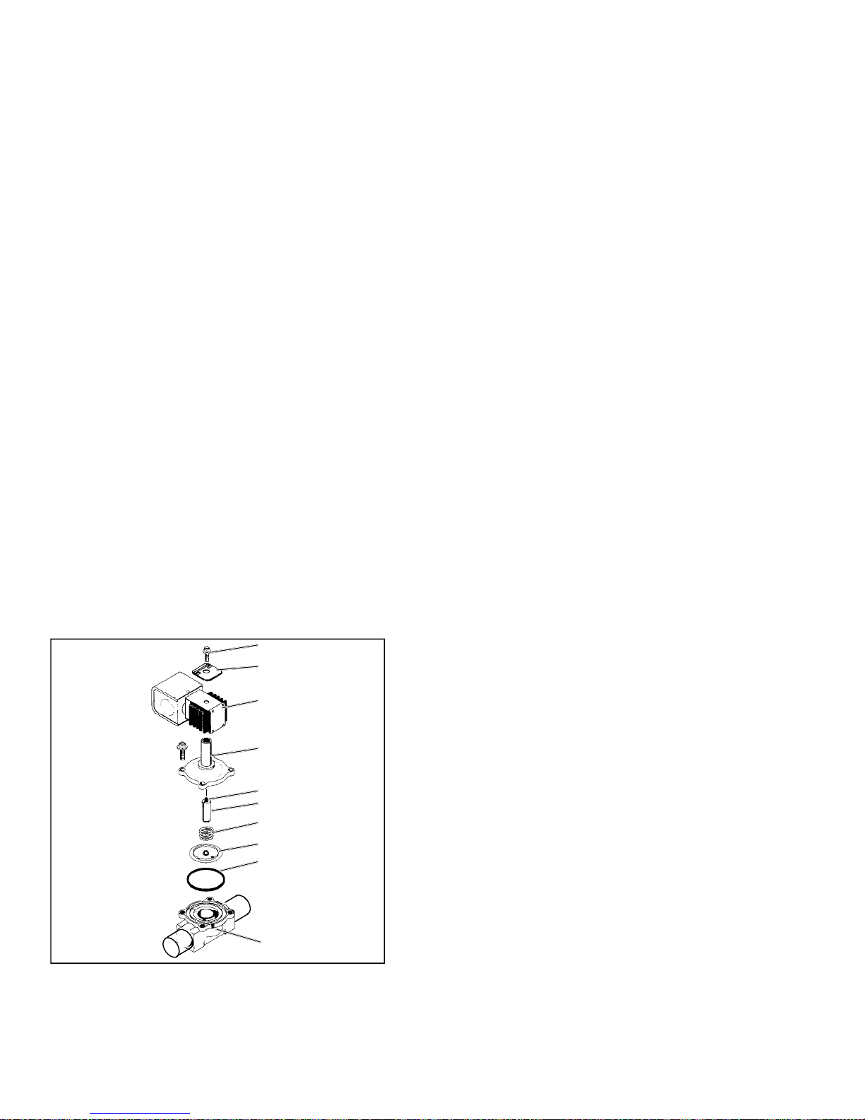
5.12 SERVICING THE HEAT VALVE
f
f
The heat valve (Figure 5--6) requires no maintenance
unless a malfunction to theinternalparts or coiloccurs.
This may be caused by foreign material such as: dirt,
scale, or sludge in the coolant system, or improper
voltage to the coil.
1. Coil Retaining Screw
2. Nameplate
3. Coil Housing
Assembly
4. Enclosing Tube &
Bonnet Assembly
5. Kick-O
6. Plunger
7. Closing Spring
8. Diaphragm
9. O-Ring
10. Valve Body
Spring
NOTE
TheOEMsuppliedheating(hot water)Solenoid
Valve is normally located outside of the
AC310/350 rooftop air conditioning system.
There are only three possible valve malfunctions: coil
burnout, failure to open, or failure to close.
Coil burnout may be caused by the following:
1. Improper voltage
2. Continuous over-voltage, more than 10% or Undervoltage of more than 15%.
3. Incomplete magneticcircuitduetotheomissionofthe
coil housing or plunger.
4. Mechanical interference with movement of plunger
which may be caused by a deformed enclosing tube.
Failure to open may be caused by the following:
1.Coil burned out or an open circuit to coil connections.
2. Improper voltage.
3. Torn diaphragm.
4. Defective plunger or deformedvalvebodyassembly.
Failure to close may be caused by the following:
1. Defective plungerordeformedvalve bodyassembly.
2. Foreign material in the valve.
3. Torn diaphragm.
1.
2.
5.12.1 Coil Replacement
a. It is not necessary to drain the coolant from the sys-
tem.
b. Place mainbatterydisconnectswitchin OFF position
and lock.
c. Disconnect wire leads to coil.
d. Remove coil retaining screw and nameplate.
e. Lift burned-out coil from enclosing tube and replace.
f. Connect wire leads and test operation.
5.12.2 Internal Part Replacement
a. Disconnect system from bus battery.
b. Open the vent fitting atthetopoftheoutlet headerof
the heater coil.
c. Draincoil by opening thedrain-cock ontheinlet tube.
d. Disassemble valve and replace defective parts.
e. Assemble valve, refill and bleed coolant lines.
5.12.3 Replace Entire Valve
a. Disconnect system from bus battery.
b. Drain coolant fromlines as previously described and
disconnect hoses to valve .
c. Disconnect wire leads to coil.
d. Remove valve assembly from bracket.
e. Install new valve and re-connect hoses. It is not ne-
cessarytodisassemblethe valvewheninstalling.
f. Refill and bleed coolant lines.
g. Connect wire leads and test operation.
T-304
3.
4.
5.
6.
7.
8.
9.
10.
Figure 5--6 Heat Valve
5.13 SERVICING THE LIQUID LINE SOLENOID
VALVE
The Liquid line solenoid valve (Figure 5--7) is very
similar to the heat valve. It requires no maintenance
unless a malfunction to theinternalparts or coiloccurs.
This may be caused by foreign material such as: dirt,
scale, orsludgein the refrigeration system, or improper
voltage to the coil.
There are only three possible valve malfunctions: coil
burnout, failure to open, or failure to close.
Coil burnout may be caused by the following:
1. Improper voltage.
2. Continuous over-voltage, more than 10% or under-
voltage of more than 15%.
3. Incomplete magnet circuit due to the omission of the
coil hosing or plunger.
4. Mechanical interface with movement of plunger
which may be caused by a deformed enclosing tube.
5--6
04/08
Page 38

Failure to open may be caused by the following:
g
y
1. Coil burnedoutoran open circuit to coil connections.
2. Improper voltage.
2.
1.
3. Defective plunger or deformedvalvebodyassembly.
Failure to close may be caused by the following:
1. Defective plunger or deformedvalvebodyassembly.
2. Foreign material in the valve.
5.13.1 Coil Replacement
a. It is not necessary to remove the refrigerant charge
from the system.
b. Disconnect system from bus battery.
c. Disconnect wire leads to coil.
d. Remove coil retaining clip and nameplate.
e. Lift failed coil from enclosing tube and replace.
f. Connect wire leads and test operation
5.13.2 Internal Part Replacement
a. Disconnect system from bus battery.
3.
4.
5.
6.
7.
8.
Figure 5--7 Liquid Line Solenoid Valve
1. Snap Cap
2. Coil Assembly
3. Enclosing Tube
Assembly
4. Plun
5.14 SERVICE V AL VES
The filter/drier (High Side) service valves (Figure 5--8)
areprovidedwith a doubleseatand agaugeport,which
allows servicing of the filter drier assembly.
er Assembl
5. Gasket
6. Piston Assembly
7. Body
8. Bracket Adapter
b. Recover and recycle system refrigerant.
c. Slowly loosen enclosing tube assembly to bleed any
remaining pressure from the valve. Disassemble
valve and replace defective parts.
d. Assemble valve and leak check.
e. Evacuate and recharge system.
5.13.3 Replace Entire Valve
a. Recover and recycle system refrigerant.
b. Remove valve assembly from bracket.
c. Disconnect wire leads to coil.
d. Disassemble newvalve,toprotectinternalparts,and
solder to lines.
e. Assemble and leak check valve.
f. Evacuate and recharge.system.
Turning the valve stem counterclockwise (all the way
out) will backseat the valve to open the line to the
system and close off the gauge port. In normal
operation, the valve is backseated to allow full flow
through the valve. The valve should always be
backseated before removing the gauge port cap.
Turning the valve stem clockwise (all the way forward)
will frontseat the valve to isolate the system and open
the gauge port.
TO DISCHARG LINE
Port To
Compressor
Service Valve
Frontseated
(clockwise)
Service Valve
Backseated
(counterclockwise)
VALVE CAP
SERVICE
PORT
VALVE
STEM
g. Connect wire leads and test operation.
04/08
5--7
Figure 5--8 Service Valve R134a (High Side)
T-304
Page 39

5.15 REPLACING RETURN AIR FILTERS
The return air filters are located behind the return air
grill, inside the vehicle.
The filters should be checked for cleanliness
periodically depending on operating conditions. A dirty
filter will restrict air flow over the evaporator coil which
may cause insufficient cooling or heating and possible
frost buildup on the coil. To remove the filters, do the
following.
a. Insure air conditioning system is in the off position.
b. Remove the return airgrillewiththefilter--diffuseras-
sembly,byturning the six 1/4 turn fastenerscounterclockwise.
Composit Frame
f. Pullfilterelement approximately 1/4inchover endsof
the diffuser.
Diffuser
Air Filter
Composit Frame
Figure 5--11
Filter, Diffuser and Composit Frame
g. Place filteranddiffuser intocompositframe, withfilter
element down (See Figure 5--11).
Return Air Filter
Figure 5--9 Return Air Grill Assembly
With Air Filter Showing
c. Remove diffuser from the bus composit frame.
Diffuser
Return Air Filter
Figure 5--10 Diffuser and Filter Element
d. Remove and replace the filter element.
e. Center diffuser on filter element.
Captive 1/4 Fastners
Figure 5--12 Return Air Grill Assembly
With Diffuser And Composit Frame Showing
h. Insert filter--diffuserassemblyintocomposit frameon
bus with the six captive 1/4 fasteners. (See
Figure 5--12)
i. Lock the six captive 1/4 turns in place by rotating
clockwise.
5.16 THERMOSTATIC EXPANSION VALVE
The thermostat expansion valve (Figure 5--13) is an
automatic device which maintains constant superheat
of the refrigerant gas leavingtheevaporator regardless
of suction pressure. The valve functions are: (a)
automatic control of refrigerant flow to match the
evaporator load and (b) prevention of liquid refrigerant
entering the compressor.Unless the valve is defective,
it seldom requires any maintenance.
T-304
5--8
04/08
Page 40

1.
2.
3.
4.
5.
4.
6.
7.
Figure 5--13 Thermostatic Expansion Valve
1..Power Head
Assembly
2..Equalizer Connection
3..Bulb
5.16.1 Valve Replacement
a. If compressor is operative perform low side pump
down to replace expansion valve. (refer to 5.5.1) If
compressor isinoperativerecover and recycle refrigerant from the system.(refer to 5.5.2)
b. Remove insulation from expansion valve bulb. (See
Figure 5--13 and Figure 5--14.)
c. Loosen retaining straps holding bulb to suction line
and detach bulb from the suction line.
d. Loosen flare nuts on equalizer line and disconnect
equalizer line from the expansion valve.
e. Check, clean and remove any foreign material from
the valve body,valveseatandmatingsurfaces. If required, replace valve body.
4..Gasket
5..Cage Assembly
6..Body Flange
7..Cap screw
3.
2.
4.
5.
1.
Figure 5--14 Thermostatic Expansion Valve Bulb
1..Suction Line
(section view)
2..TXV Bulb Clamp
3..Nut & Bolt (clamp)
a. Open top cover.
b. Remove Presstite insulation from expansion valve
bulb and suction line.
c. Loosenone TXV bulb clamp and make sure area un-
der clamp is clean.
d. Place temperature thermocouple in contact with the
suction tube and parallel to the TXV bulb, and then
secure loosened clamp making sure both bulb and
thermocouple are firmly secured to suction line. (See
Figure 5--14). Reinstall insulation around the bulb.
e. Connect an accurate low pressure gauge to the low
pressure port.
and Thermocouple
4..Thermocouple
5..TXV Bulb (Shown
in the 4’clock
position)
NOTE
R--134a valves are adjustable. Valves are presetatthefactory.
f. Leak check the new valve and evacuate and dehy-
drate the system. (Refer to paragraph 5.7.)
g. The thermal bulb is installed below the center of the
suction line (four or eight o’clock position). This area
must be clean to ensure positive bulb contact. Strap
thermal bulb to suction line. Ensure that retaining
straps are tight and renew insulation.
h. Fasten equalizer line to the expansion valve.
i. Evacuate and recharge the system.
j. Run the coach for approximately 30 minutes on fast
idle.
k.Check refrigerant charge. (Refer to 5.8.1)
5.16.2 Superheat Measurement
NOTE
All readings must be taken from the TXV bulb
location and out of the direct air stream.
04/08
f. Close top cover being careful to route thermocouple
sensing wire and gauge hose outside the unit.
g. Start bus and run on fast idle until unit has stabilized,
about 20 to 30 minutes.
NOTE
Whenconductingthis test,thesuctionpressure
must be at least 6 psig (0.41bar)below theexpansion valve maximum operating pressure
(MOP). Refer to paragraph 1.3 for MOP.
h. From the temperature/pressurechart, determine the
saturation temperature corresponding to the evaporator outlet pressure.
i. Notethe temperature ofthesuctiongas attheexpan-
sion valve bulb. Subtract the saturation temperature
from this temperature. The difference is the superheat of the suction gas.
5--9
T-304
Page 41

j. Thesuperheatmaycyclefromalowto high reading.
Monitorthesuperheat takingreadingsevery 3--5minutes for a total of 5--6 readings. Calculate the superheats, add the readings and divide by the number of
readings taken todetermine average superheat. The
superheat should be 18 ± 3°F.
k. Ifsuperheatis notwithintolerance,replacethevalve.
T-304
5--10
04/08
Page 42

Table 5--1. R-134a Temperature - Pressure Chart
Temperature
°F °C
-- 40 -- 4 0 14.6 49.4 37.08 0.49
.35 .37 12.3 41.6 31.25 0.42
-- 30 -- 3 4 9.7 32.8 24.64 0.33
-- 25 -- 3 2 6.7 22.7 17.00 0.23
-- 20 -- 2 9 3.5 11.9 8.89 0.12
-- 18 -- 2 8 2.1 7.1 5.33 0.07
-- 16 -- 2 7 0.6 2.0 1.52 0.02
Temperature Pressure
°F °C
-- 14 -- 2 6 0.4 1.1 0.03 0.03
-- 12 -- 2 4 1.2 8.3 0.08 0.08
-- 10 -- 2 3 2.0 13.8 0.14 0.14
-- 8 --22 2.9 20.0 0.20 0.20
-- 6 --21 3.7 25.5 0.26 0.26
-- 4 --20 4.6 31.7 0.32 0.32
-- 2 --19 5.6 36.6 0.39 0.39
0 -- 1 8 6.5 44.8 0.46 0.45
2 -- 1 7 7.6 52.4 0.53 0.52
4 -- 1 6 8.6 59.3 0.60 0.59
6 -- 1 4 9.7 66.9 0.68 0.67
8 -- 1 3 10.8 74.5 0.76 0.74
10 -- 12 12.0 82.7 0.84 0.83
12 -- 11 13.2 91.0 0.93 0.91
14 -- 10 14.5 100.0 1.02 1.00
16 -- 9 15.8 108.9 1.11 1.09
18 -- 8 17.1 1 17.9 1.20 1.18
20 -- 7 18.5 127.6 1.30 1.28
22 -- 6 19.9 137.2 1.40 1.37
24 -- 4 21.4 147.6 1.50 1.48
26 -- 3 22.9 157.9 1.61 1.58
“/hg cm/hg kg/cm@ bar
psig kPa kg/cm@ bar
Vacuum
Temperature Pressure
°F °C
28 -- 2 24.5 168.9 1.72 1.69
30 -- 1 26.1 180.0 1.84 1.80
32 0 27.8 191.7 1.95 1.92
34 1 29.6 204.1 2.08 2.04
36 2 31.3 215.8 2.20 2.16
38 3 33.2 228.9 2.33 2.29
40 4 35.1 242.0 2.47 2.42
45 7 40.1 276.5 2.82 2.76
50 10 45.5 313.7 3.20 3.14
55 13 51.2 353.0 3.60 3.53
60 16 57.4 395.8 4.04 3.96
65 18 64.1 441.0 4.51 4.42
70 21 71.1 490.2 5.00 4.90
75 24 78.7 542.6 5.53 5.43
80 27 86.7 597.8 6.10 5.98
85 29 95.3 657.1 6.70 6.57
90 32 104.3 719.1 7.33 7.19
95 35 114.0 786.0 8.01 7.86
100 38 124.2 856.4 8.73 8.56
105 41 135.0 930.8 9.49 9.31
110 43 146.4 1009 10.29 10.09
115 46 158.4 1092 11.14 10.92
120 49 171.2 1180 12.04 11.80
125 52 184.6 1273 12.98 12.73
130 54 198.7 1370 13.97 13.70
135 57 213.6 1473 15.02 14.73
140 60 229.2 1580 16.11 15.80
145 63 245.6 1693 17.27 16.93
150 66 262.9 1813 18.48 18.13
155 68 281.1 1938 19.76 19.37
psig kPa kg/cm@ bar
04/08
5--11
T-304
Page 43

SECTION 6
ELECTRICAL
6.1 INTRODUCTION
This section includes electrical wiring schematics. The
schematics shown in this section provides information
for theAC310 andAC350 modelrooftopair conditioning
units which are fitted with eight (8) and twelve (12)
single--shafted or four (4) and six (6) double--shafted
evaporator blower/motor assemblies and four (4) or six
UNIT
AC 310 Thermostat With Manual Reheat Figure 6--1 Thru Figure 6--6
AC 350 BT324 Figure 6--7 Thru Figure 6--13
AC 310/AC350 Thermostat One/Two Compressors Figure 6--14 To Figure 6--18
CONTROLLER FIGURE NUMBERS
(6) condenser fan motors. Figure 6--1 through
Figure 6--6shows the Thermostat with manualre--heat.
Figure 6--7 thru Figure 6--13 shows the CSDD BT324
controller usedwiththeAC310 single and dualsystems
and the AC350 single loop with transit compressors.
Figure 6--14 thru Figure 6--18 shows Thermostat
control with one or two compressors.
6--1
T--30404/08
Page 44

EVAPORATOR
Compressor Clutch
Convection HeatingConnection
CONTROL PANEL
HP Switch
LP Swi tch
HEATING VALVE
Y31A
M31M
WATER PUMP HEATING
Figure 6--1 System Controls (Typical)
G
CONDENSER
R1N
R2N
VERSION B
Operation Board
S3A
S1A
VERSION A
Operation Board
S2A
S1A
AC 310 100A @ 24VDC
AC 350125A @24VDC
FOM
AC310 OPTION 150A @12VDC
ALTERNATOR
Battery 24 VDC
6--2T--304
04/08
Page 45

B+
OR
11
810
1
UR
24V12V
-- --
LL
Sensors
UK
UH
BKGY
Clutch
OGRD
REF: 98- -62- -62668- -00
Y2A
V5
V4
REL 1 REL 2
Cooling Heating
WH
Inside sensor
Sensor
1 9162435
Thermostat
7
Poti.
WH
BN
WH
B1N
X20
91011
2
1
Liquid Line Valve
Y1A
or
swor
B+
RD
BKYE
U5
15A
F1A
BKBU
U2
R1N
Temperature setting
Operation Board
OEM SUPPLIED
*
Dash Control
858787a
K4A
8630
Other Signal Indicating
Vehicle Electrical System
Is Ready To Operate AC
System
OR
WHBU
WH
V1
OGRD
87
30
WHRD
86 87a
85
U3
K1A
V3
WHOG
34 5
WHYE
V2
RDWH
X3
12
WH
BKRD
Climate
S2A
High
Vent 2
1
S1A
3
7
Low
Vent 1
5A
F01A
Operation Board
T----Splice Into Freightliner
Wire 393 At Hydraulic
Wire 393
87A
86
87
Figure 6--2 Manual Controls With Manual Reheat Control (Sheet 1)
Brake Module
*
30
A/C Power
30 A Relay
85
Battery
Evap. Low
Evap. High
Cond. Mtrs.
6--3
Breaker 10
*
5A
T--30404/08
Page 46

M31M
OEM SUPPLIED
*
RD
12VDC
Ov e r -- -- R i d e S w i t c h
10A
F2A
25F
60F
=
B21F
M
Waterpump heating
Y31A
Heating valve
L P -- -- s wi t c h
P
Y8M
Compressor clutch
NOTE A
Breaker
15A
*
A/C Low Voltage
BK
60 Switch --- - Closes On Temperature Rise
25 Switch --- - Opens On Temperature Decrease
87
BK
30
87a85
86
K3A
CLR1
86
85
8787a
30
BU
Note A
BK
8
*
CR1
85
8687
30
87a
B20F
H P -- -- s wi t c h
P
B+
RD
OR
CLR2
86
85
BKGY
UK
10A 10A
F3A F4A
OGRD
87
30
87a
86
85
K2A
LL
87
30
87a
UH
*
CR2
868787a
85
30
H P -- -- s wi t c h
L P -- -- s wi t c h
P
B10F
B11F
P
Y7M
Figure 6--3 Manual Controls With Manual Reheat Control (Sheet 2)
Compressor clutch
T----Stat
LL Solenoids
REF: 98- -62668- -00
6--4T--304
04/08
Page 47

B+
U2
U4
(OPTIONAL)
REF: 98- -62668- -00
15A
15A
15A
30
8786
GN
F4M
8585
K5M
F3M
BKGN
GN
BKBU
3086
BN
85
85 87
BKOG
K6M
3086
BKWH
K4M
6
5
BN
WHGN
M3M M4M
MM
4
WHOG
Figure 6--4 Evaporator Motors 1 -- 4
M2MM1M
M
30
BK
F2M
BKYE
3086
BN
3
WHYE
86 87
K2M
15A
F1M
GN
BKBU
85 87
87
85 87
BKRD
K3M
3086
BKBU
2
BN
M
K1M
+
F01M
1
BLACK
X2
150 AMP
SAO
WHRD
+
-- --
BATTERY 12 VDC
6--5
T--30404/08
Page 48

B+
U2
U5
(Optional)
K13M
8630
8587
15A
15A
15A
F6M
87a
30
F8M
85
86 87
K11M
GN
BKBU
WHOG
WHGN BU
3086
BN
85
87
85 87
K12M
3086
WHBK
K10M
15
14
1310
M
BKGN
BN
M7M M8M
M
BKOG
F7M
M6M
MM
30
GY
WHYE
87
3086
BN
12
BKYE
Figure 6--5 Evaporator Motors 5 -- 8
85
86 87
K8M
15A
F5M
B+
U2
GN
BKBU
WHRD
8587
85
K9M
3086
WHBU
K7M
11
BN
BKRD
M5M
X2
U4
REF: 98--62668--00
6--6T--304
04/08
Page 49

B+
U2
BKBU
U5
BKYE
U3
OGRD
REF: 98--62668--00
(Optional)
15A
85
86
GNYE
Figure 6--6 Condenser Motors
87
30
K14M K15M
85
86
87
30
U2
B+
U5
15A
15A 15A
F13M F14M F15M F16M
GNBU
GNWH
MMM
10 13 14 15
X1
GNOG
M
WHITE
M21M M22M M23M M24M
6--7
T--30404/08
Page 50

UL SWITCHES
Y7M Compressor Clutch
EVAPORATOR
Convection HeatingConnection
CONTROL PANEL
UNLOADER
HP Switch
LP Swi tch
HEATING VALVE
Y31A
M31M
WATER PUMP HEATING
CONDENSER
Figure 6--7 BT324 Controls With (1) Compressor (AC350)
BT 324
ALT
DASH SWITCH
ALTERNATOR WITH
6--8T--304
04/08
Page 51

REF: 98--62668--00
CONTROL PANEL
WP
WP -- WATER PUMP
HSV -- HEATING SOLENOID VALVE
U2 -- EVAPORATOR RELAY -- COIL
UReg -- SPEEDCONTROL POWER
U4 -- EVAPORATOR RELAY -- COIL
HSV
05G
Clutch
Compressor
05G -- 05K OPTION
(RAS)
Figure 6--8 BT324 Control Circuit (AC350)
BT324
CONTROLLER
INSIDE SENSOR
6--9
5A 5A
5A
OPTION
(ATS)
OUTSIDESENSOR
T--30404/08
Page 52

U1
U2
U4
Ureg
Ureg
REF: 98--62668--00
AC310 M1M -- M4M
AC350 M1M -- M6M
INSTALLEDBLOWERS
K6M
86
M6M
87a85
X10.2
963
K5M
86
85 85
30 30
15A
F10M F11M F11M
F9M
12
X10.2
U3
U3a
K4M
86
30
87a 87 87a 87 87
K3M
86
8587a 87
CONTROL PANEL
30
15A 15A
15A
F8M
M4M M5M
F7M
F6M
X10 X10 X10
X10.2
EVAPORATOR MOTORS
M3M
F5M
Figure 6--9 BT324 Evaporator Motors (AC350)
86
30
RDBU
K2M
F4M
15A
87a 87 85
X10.1 X10.1 X10.1 X10.1 X10.1
M2M
X10 X10
X10.2 X10.2
4 7 10 13 14 11 15
86
30
K1M
87 85
87a
15A
F2M F3M
1
F1M
X2
X10.1
MMMMMM
M1M
X10
X10.2
2xRD 16
3A
Fma
BN
FOM
125A --AC350
100A --AC310
+
+
ALT
6--10T--304
04/08
Page 53

+U4A
UVd
Ureg
UFri
UKo
X10.1
GY(GN)
GY(BN)
WHRD
X1
+
BU
X10
WHGN
RDBU
BUWH
CONTROL PANEL
GY(OG)
X10.2
SPEED CONTROLLERCONNECTION
2
1pol.
1
FRESH AIR FLAP
9
6
X2
7
8
X20 X21
2
1pol.
1
U4A
(OPTIONAL)
LIQUIDLINEVALVE
REF: 98--62668--00
M26M
M
15A
U2
K9M
85
15A 15A
30
87a 87 86
M25M
Figure 6--10 CSDD BT324 Condenser Motors
K8MK7M
85
87 86
30
87a
15A 15A 15A
8687a 87
85
15A
30
F13M F14M F15M F16M F17M F18M
14 15 12 11
10 13
X1
MMMM
CONDENSER BLOWER MOTORS
M
M21M M22M M23M M24M
M
U1
U4
Ureg
6--11
AC310 M21 -- M24M
AC350 M21 -- M26M
CONDENSER MOTORS
T--30404/08
Page 54

Fans
8....F1M -- F12M = Individual Evaporator
Fans
9....U Reg = Evaporator Speed Regulation
10...X1 = Condenser Fans
(M1M -- M6M)
5....K7M -- K9M = Individual Condenser Fans
(M21M -- M26M)
6....Fuse = Boost Pump & Heat Valve
7....F13M -- F18M = Individual Condenser
Solenoid -- Condenser Fans
1....K1A = Compressor Clutch -- LiquidLine
2....K2A = Heat Valve -- Boost Pump
3....K3A = Evaporator Fans
4....K1M -- K6M = Individual Evaporator Fans
11...X2 = Evaporator Fans
Dash To Unit Interface Plug
12...X3 -- X4 (Not Shown On Drawing) =
+
K1M
F1M 10A
F2M 10A
K2M
F3M 10A
K3M
F4M 10A
F5M 10A
X2
F6M 10A
K4M
F7M 10A
F8M 10A
K5M
K1A
K2A
K3A
+
GND
Relay Board
K6M
K7M
F9M 10A
F10M 10A
F11M 10A
F12M 10A
F13M 15A
K8M
K9M
F14M 15A
F15M 15A
F16M 15A
F17M 15A
F18M 15A
26.38.08.001
Ureg
Part Number
Figure 6--11 AC350 With BT324 Control
K7M -- K9M
X1
--
Contact arrangement
Connect X1 -- X2
U3
U3A
Top View
SUTRAK SCHMATIC #65, 01, 28, 056--01--3
6--12T--304
K1m -- K4M K7M -- K8M
K1M -- K6M
+
RELAYS FOR EVAP.MOTORS RELAYS FOR COND. MOTORS
UNIT
AC350
AC310
04/08
Page 55

1
(FROM)
(FROM)
(FROM)
05G -- 05K OPTION
LEGEND
HPS -- HIGH PRESSURE SWITCH
HSV -- HEATINGSOLENOID VALVE
LPS -- LOWPRESSURESWITCH
WP -- WATERPUMP
UPS1 -- UNLOADER PRESSURE SWITCH #1
UPS2 -- UNLOADER PRESSURE SWITCH #2
UPS3 -- UNLOADER PRESSURE SWITCH #3
UV1 -- UNLOADER VALVE #1
SUTRAC PT.#60--01--28--126
UV2 -- UNLOADER VALVE #2
SCHEMATIC 65--01--28--056-- 01--3
Figure 6--12 CSDD BT324 Control Circuit
AC--310/350 ELECTRICAL PANEL 24 V
100 Amp 24 VDC AC310
125 Amp 24 VDC AC350
X3 PLUG
X4 PLUG
6--13
T--30404/08
Page 56

5A
BT--324
1
CSDD BT324
5
2
9
13
6
8
4
12
16
20
17
18
3
11
15
19
23
21
22
10
14
Reserve
24
Not Used
7
Digital Controller
All Outputs 0.5 A Max.
5A
5A
Blower Speed2
a) Blower ON
b) BlowerSpeed 1
Fresh Air
24 V(15)
Load
Relay
Valve
Blower SpeedSignal
DRM
P
>
P
Pressure
Switches
<
or 12 V
M
NTC
NTC
(Optional)
RS232 RxD
Reat
Relay
RS232 TxD
Figure 6--13 CSDD BT324
Free
Wheeling
Input Power
Ground
Night Light
Alternator
Compressor Failure Signal(Optional)
Diode
Blower Motor
Clutch
Compressor
Outside Sensor
Inside Sensor
(Optional)
OffOnOff
On
VDC
12 or 24
Off
OffOnOn
Blower Speed2 Blower Speed1
012
Speed
Blower ControlOptions a) SpeedController
(Software Selectable) b) Steps
6--14T--304
3
04/08
Page 57

+
U2U4Ureg
U1
86
86
86
30
30
30
K5M K6M
K4M
87a 87 85
85
87a 87 85 87a 87
F12M
F9M F10M F11M
F8M
Ureg
3
6
9
12
15
11
X10.1 X10.1
X10
X10.1
X10.1
X10 X10
X10
X10
X10
X10.2
X10.2
X10.2
X10.2
X10.2
X10.2
M
M
MMM
M11M M12M
M10M
M7M M8M M9M
M1M -- M8M
M1M -- M12M
AC310
AC350
INSTALLED BLOWERS
14
K3M
85
86
30
10A 10A 10A 10A 10A 10A 10A 10A 10A
86
30
87a 87 85 87a 87
K1M K2M
8587a 87
86
+
30
--
BN6
F3M F4M F5M F6M F7M
F2M
10A 10A 10A
F1M
1 4 7 10 13
X2
X10.1 X10.1 X10.1 X10.1
X10 X10 X10
X10.1 X10.1 X10.1
X10
X10.1
X10
X10
FOM
X10.2
X10.2
X10.2
X10.2
X10.2
X10.2
M
M6M
EVAPORATOR MOTORS
MM
M5M
M4M
MMMM
M1M M2M M3M
+
--
24 VDC
BATTERY
Figure 6--14 Thermostat (One/Two Compressors)
6--15
T--30404/08
Page 58

+
Grey
X10.1
+
X10
Yellow
Red
X10.2
Brown
Green
M
Installed Motors
M21M -- M24M
AC310
M21M -- M26M
AC350
MMM
+
Figure 6--15 Thermostat (One/Two Compressors)
MM
CONDENSER MOTORS
M
6--16T--304
04/08
Page 59

23
23
U3
2
R1N
2
V6
Installed InUnits WithHeating
3
3
1
30
87a87
85
86
X3.4
3086
87a 87
85
K4A K5A
9641
F1
F2
1
7
A1P
9
1
5
HEATING
3
B1N
280P/282P
THERMOSTAT
TEMP. SENSOR
11
1
4
COOLING
2
610
K2A
86
8587a87
K6A
B1
3086
87a
8
85
X5
K3A
V7
11
B2N
2
BKYE
1
A1
4
BKRD
10
OPTION
Fresh Air Flap
YM3
RD6
U1
2
*
1
D5
V5
1
3
4
V1
V2 V4
V3
B5
347589
Operation Panels
Figure 6--16 Thermostat (One/Two Compressors)
6
15A
U2
F1A
X10
+
WHBU
U2
UR
WHYE
U3
GND
BN6
WHGN
U3
Ureg
87
30
87a
86
85
K1A
12
X4
D+61
Alternator
6--17
T--30404/08
Page 60

2
87
30
87a
10A
F3A
31
85
86
K7A
Option
10 7 511
Compressor Unloader
OPTION
2
1
4
Unloader Valve
Y8A
B11N
+
X3.5
2
10A
3/B15
UNIT WITH 1 COMPRESSOR
F2A
X5
U3
GN
LP Switch
1
4
--
B1F
+
1
B11F
HP Switch
Y7A
4
2
+
--
Liquid Line Valve
Y7N
Compressor Clutch
21
10A
F3A
3
87
3086
87a
85
K7A
Option
10 7 5
2
LP--Switch
1
4
4
HP--Switch
1
2
Figure 6--17 Thermostat (One/Two Compressors)
B2F
X3.5
GN
2
B21F
Compressor Clutch
Y8M
Y7A
1
Liquid Line Valves
Y6A
UNIT WITH 2 COMPRESSORS
X20
10A
3/B15
F2A
U3
11
X5
2
LP Swi tch
1
4
B1F
+
4
HP Switch
1
2
+
B11F
Compressor Clutch
Y7M
6--18T--304
04/08
Page 61

OPTION
Fresh Air Flap
1
5
VERSION B
R1
S3A
S1A
3
71
V5V1
1
2
89
5
7
(OPTION 2)
CONTROL P ANEL
34
2
Speed S etting
X4
Ventilation: Stepless
Evaporator Blowers
Clima Operation:
Stepless, depending
on temperature
OPTION
9
Fresh Air Flap
5
1
VERSION A
S3A
Figure 6--18 Thermostat (One/Two Compressors)
1
5
58
7
34
Clima
S2A
1
S1A
3
7
(OPTION 1)
CONTROL P ANEL
2
X4
Evaporator Blowers
Ventilation -- 2 Steps
6--19
T--30404/08
Page 62

INDEX
A
Air Filters, 5--7
Apex Unit, 1--2
C
Circuit Breaker, 1--8
Clutch, 2--3
Compressor, 1--6, 1--7
Compressor Clutch Control, 2--3
Condenser Fan, 1--8
Condensing Section, 1--2
Cooling Mode, 2--2
D
DESCRIPTION, 1--1
M
Maintenance Schedule, 5--1
Manifold Gauge Set, 5--1
Modes Of Operation, 2--2
N
Noncondensibles, 5--4
O
Operating Controls, 1--7
Operating Instructions, 2--1, 3--1
OPERATION, 2--1, 3--1
P
Pre--Trip Inspection, 2--1, 3--1
Pump Down, 5--2
E
ELECTRICAL, 6--1
Evacuation, 5--3
Evaporator, 1--4, 1--6
Evaporator Fan, 1--7, 2--2
Evaporator Fan Speed Selection, 2--3
F
Filter--Drier, 5--5
Fuse, 1--8
H
Heat Valve, 5--5
Heating Cycle, 1--8
Heating Mode, 2--2
High Pressure Switch, 1--7, 1--8
R
Refrigerant Charge, 1--7, 5--2, 5--3, 5--4
Refrigerant Removal, 5--3
Refrigeration Cycle, 1--8
S
SAFETY, Safety--1
SERVICE, 5--1
Starting, 2--1, 3--1
Stopping, 2--1, 3--1
Superheat, 5--9
T
Temperature Control, 2--2
Temperature Pressure Chart, 5--10
Temperature Sensor, 1--8
Thermostatic Expansion Valve, 1--7, 5--8
TROUBLESHOOTING, 4-- 1
L
Liquid Line Solenoid, 5--6
Low Pressure Switch, 1--7, 1--8
T--304 04/08
W
Water T emperature Switch, 1--7
Index --1
Page 63

A member of the United Technologies Corporation family. Stock symbol UTX
©2008 Carrier Corporation D Printed in U. S. A. 0408
Carrier Transport Air Conditioning
50 Grumbacher Road
York PA 17406 USA
Tel: 1--800--673--2431
Fax: 1--717--764--0401
Carrier Transicold Division,
Carrier Corporation
Transport Air Conditioning Group
P.O. Box 4805
Syracuse, N.Y. 13221 U.S A
www.carrier.transicold.com
 Loading...