

Page 1
58PAV
HEATING A COOLING
Upflow Induced-Combustion Furnaces
Installation, Start-Up, and Operating Instructions
Sizes 035-125,
NOTE: Before beginning the installation, READ THESE
INSTRUCTIONS CAREFULLY AND COMPLETELY.
SAFETY CONSIDERATIONS
Installation and servicing of heating equipment can be haz
ardous due to gas and electrical components. Only trained
and qualified personnel should install, repair, or service
heating equipment.
Untrained personnel can perform basic maintenance func
tions such as cleaning and replacing air filters. All other
operations must be performed by trained service personnel.
When working on heating equipment, observe precautions
in the literature, tags, and labels attached to or shipped
with the unit and other safety precautions that may apply.
Follow all safety codes. In the United States, follow all
safety codes including the National Fuel Gas Code NFPA
No. 54-1988/ANSI Z223.1-1988. In Canada, refer to the cur
rent edition of the National Standard of Canada CAN/CGAB149.1- and .2-M86 Natural Gas and Propane Gas Installa
tion Codes. Wear safety glasses and work gloves. Have fire
extinguisher available duriag startup and adjustment pro
cedures and service calls.
Recognize safety information: This is the safety-alert symognize
A. VI
bol A. When you see this symbol on the furnace and in
instructions or manuals, be alert to the potential for per
sonal injury.
Understand the signal word—DANGER, WARNING, or
CAUTION. These words are used with the safety-alert sym
bol. DANGER identifies the most serious hazards which
will result in severe personal injury or death. WARNING
signifies a hazard that could result in personal injury or
death. CAUTION is used to identify unsafe practices, which
would result in minor personal injury or product and prop
erty damage.
Table 1—Minimum Clearances From
Combustible Materials (In Ins.)
Size
Sides—Single-Wall Vent 1 0
Type B-1 Double-Wall Vent
Back
Top of Plenum
Vent Connector—Single-Wall Vent
Type B-1 Double-Wall
Vent
Front—Single-Wall Vent
Type B-1 Double-Wall Vent
Service
NOTES:
1. Provide 30-in. front clearance for servicing. An open door in front of the
furnace can meet this requirement.
2. A minimum clearance of 3 ins. must be provided in front of the furnace
for combustion air and proper operation.
035 and 055 075 thru 125
0 0
0 0
1 1
6 6
1 1
6 6
3 ■ 3
30 30
These instructions cover minimum requirements and con
form to existing national standards and safety codes. In
some instances, these instructions exceed certain local
codes and ordinances, especially those that may not have
kept up with changing residentieil construction practices.
We require these instructions as a minimum for a safe
installation.
INTRODUCTION
The design of the upflow gas-fired furnace is A.G.A./CGA
certified for natural and propane gas and for instaUation on
combustible flooring, in alcoves, attics, basements, closets,
or utility rooms. The design of this furnace line is not
A.G.A./CGA certified for installation in mobile homes, rec
reation vehicles, or outdoors.
Before instalhng the furnace, refer to the current edition of
the National Fuel Gas Code NFPA No. 54-1988/ANSI
Z223.1-1988. Canadian installations must be installed in
accordance with CAN/CGA.B149 Installation Codes and aU
authorities having jurisdiction. For further information, the
National Fuel Gas Code is available from National Fire
Protection Association Inc. Batterymarch Park, Quincy,
MA 02269, American Gas Association, 1515 Wilson Boule
vard, Arlington, VA 22209, or from Literature Distribution.
Installation must conform to the regulations of the serving
gas supplier and the local building, heating, and plumbing
codes in effect in the area in which the installation is made,
or in the absence of local codes, with the requirements of the
National Fuel Gas Code.
A CAUTION
Application of this furnace should be indoors with spe
cial attention given to vent sizing and material, gas
input rate, air temperature rise, and unit sizing.
Improper installation or misapplication of the furnace
can require excessive servicing or cause premature
component failure.
This furnace is designed for a minimum continuous return
air temperature of 60 degrees F DB or an intermittent oper
ation down to 55 degrees F DB such as when used with a
thermostat night setback. Return air temperature must not
exceed a maximum of 85 degrees F DB.
Manufacturer reserves the right to discontinue, or change at any time, specifications or designs without notice and without incurring obiigations.
Book] 1 I 4 PC 101 Catalog No. 565-913 Printed in U.S.A. Form58PA-1SI Pg 1 5-90 Replaces: New
Tab 16a i 8a
Page 2
RETURN AIR.
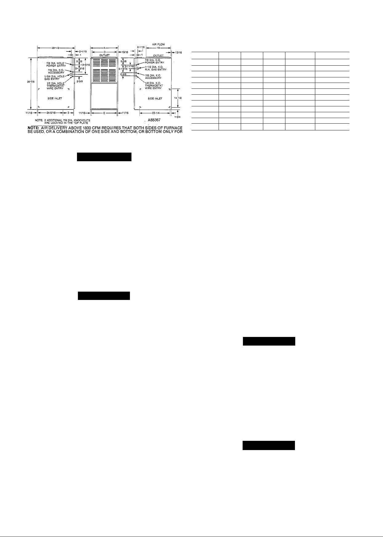
Fig. 1 —Dimensional Drawing
A WARNING
Improper installation, adjustment, alteration, service,
maintenance, or use can cause carbon monoxide poison
ing, explosion, fire, electrical shock, or other conditions
which may cause personal injury or property damage.
Consult a qualified installer, service agency, local gas
supplier or your distributor or branch for information
or assistance. The qualified installer or agency must use
only factory authorized and fisted kits or accessories
when modifying this product. A failure to foUow this
warning can cause electrical shock, fire, personal injury,
or death.
For accessory installation details, refer to the applicable
instruction literature.
NOTE: Remove aU shipping brackets and materials before
operating the furnace.
I. LOCATION
A. General
A CAUTION
Do not install furnace in a corrosive or contaminated
atmosphere. Make sure all combustion and circulating
air requirements are adhered to, in addition to eiU local
codes and ordinances.
Do not use this furnace during construction when adhe
sives, sealers, and/or new carpets are being installed. If
the fm-nace is required during construction, use clean
outside air for combustion and ventilation. Compounds
of chlorine and fluorine when burned with combustion
air form acids which will cause corrosion of the heat
exchangers and metal vent system. Some of these com
pounds are: paneling and dry waU adhesives, paints,
thinners, masonry cleaning materials, and many other
solvents commonly used in the construction process.
Locate the furnace close to the chimney/vent and as near
the center of the air distribution system as possible. The
furnace should be installed as level as possible.
When a furnace is installed so that the supply ducts carry
air to areas outside the space containing the furnace, the
return air must also be handled by a duct(s) sealed to the
furnace casing and terminating outside the space containing
the furnace.
Provide ample space for servicing and cleaning. Always
comply with the minimum fire protection clearemces shown
on the unit rating plate. This furnace shall not be installed
directly on carpeting, tüe, or any combustible material other
than wood flooring.
Table 2—Dimensions (In Ins.)
Vent Conn
Size
035-EC
035-GC 14-3/16 12-9/16
055-EC 14-3/16 12-9/16
055-GC 14-3/16 12-9/16
075-GC 17-1/2 15-7/8
075-JC 21
090-GC
090-JC 21
090-LC 24-1/2 22-7/8 23
110-JC
110-LC 24-1/2 22-7/8 23
125-LC
A D
14-3/16 12-9/16
17-1/2
21
24-1/2
19-3/8
15-7/8
19-3/8
19-3/8
22-7/8
E
12-11/16
12-11/16
12-11/16
12-11/16
16
19-1/2
16
19-1/2
19-1/2
23
4
4
4 126
4 128
4 143
4 147
4 153
4 159
4 176
5
5
5 196
B. Location With Respect to Cooling Equipment
The coofing coil must be installed parallel with, or on the
downstream side of, the furnace to avoid condensation in
the heat exchangers. When installed parallel with a furnace,
dampers or other means used to control the flow of air must
prevent chilled air from entering the unit. If the dampers
are manually operated, they must be equipped with means
to prevent operation of either unit unless the damper is in
the full-heat or fuU-cool position.
C. Hazardous Locations
When the furnace is installed in a residential garage, it must
be installed so that the burners and ignition source are
located no less them 18-ins. above the floor. Also, the fur
nace should be protected from physical damage by vehicles.
When a furnace is installed in public garages, airplane han
gars, or other buildings having hazardous atmospheres, the
unit must be installed in accordance with the recommended
good practice requirements of the National Fire Protection
Association, Inc.
II. AIR FOR COMBUSTION AND VENTILATION
Provisions for adequate combustion and ventilation air
must be provided in accordance with Section 5.3, Air for
Combustion and Ventilation, of the National Fuel Gas Code,
ANSI Z223.1-1988, or applicable provisions of the local
building codes.
Canadian installations must be installed in accordance with
CAN/CGA.B149 Installation Codes, and aU authorities hav
ing jurisdiction.
Ship. Wt
116
118
171
186
A CAUTION
Air for combustion must not be contaminated by halo
gen compounds, which include fluoride, chloride, bro
mide and iodide.
These elements are found in aerosol sprays, detergents,
bleaches, cleaning solvents, salts, air fresheners, and
other household products.
AU fuel burning equipment must be supplied with air for
combustion of the fuel. Sufficient air MUST be provided to
insure there wfll not be a negative pressure in the equipment
room or space. In addition, a positive seal MUST be made
between the furnace cabinet and the return-air duct puUing
air from the burner area and draft safeguard opening.
A CAUTION
The operation of exhaust fans, kitchen ventilation fans,
clothes dryers, or fireplaces could create a negative
pressure condition at the furnace. Make up air must be
provided for the ventilation devices, in addition to that
required by the furnace.
WA
Page 3
Combustion air requirements are determined by whether
the fiunace is in an UNCONFINED or CONFINED space.
A confined space is a space whose volume is less than 50
cubic ft per 1000 Btu per hour of the total output rating for
aU appliances installed in that space.
I
A. Unconfined Space
An unconfined space must have at least 50 cubic ft for each
1000 Btuh of input for all the appliances (i.e. furnaces,
clothes dryer, water heaters, etc.) in the space.
For Example:
Minimum Sq Ft
58PAV Furnace
Input Btuh
with
7-1/2 Ft Ceiling
1. All air from inside the structure
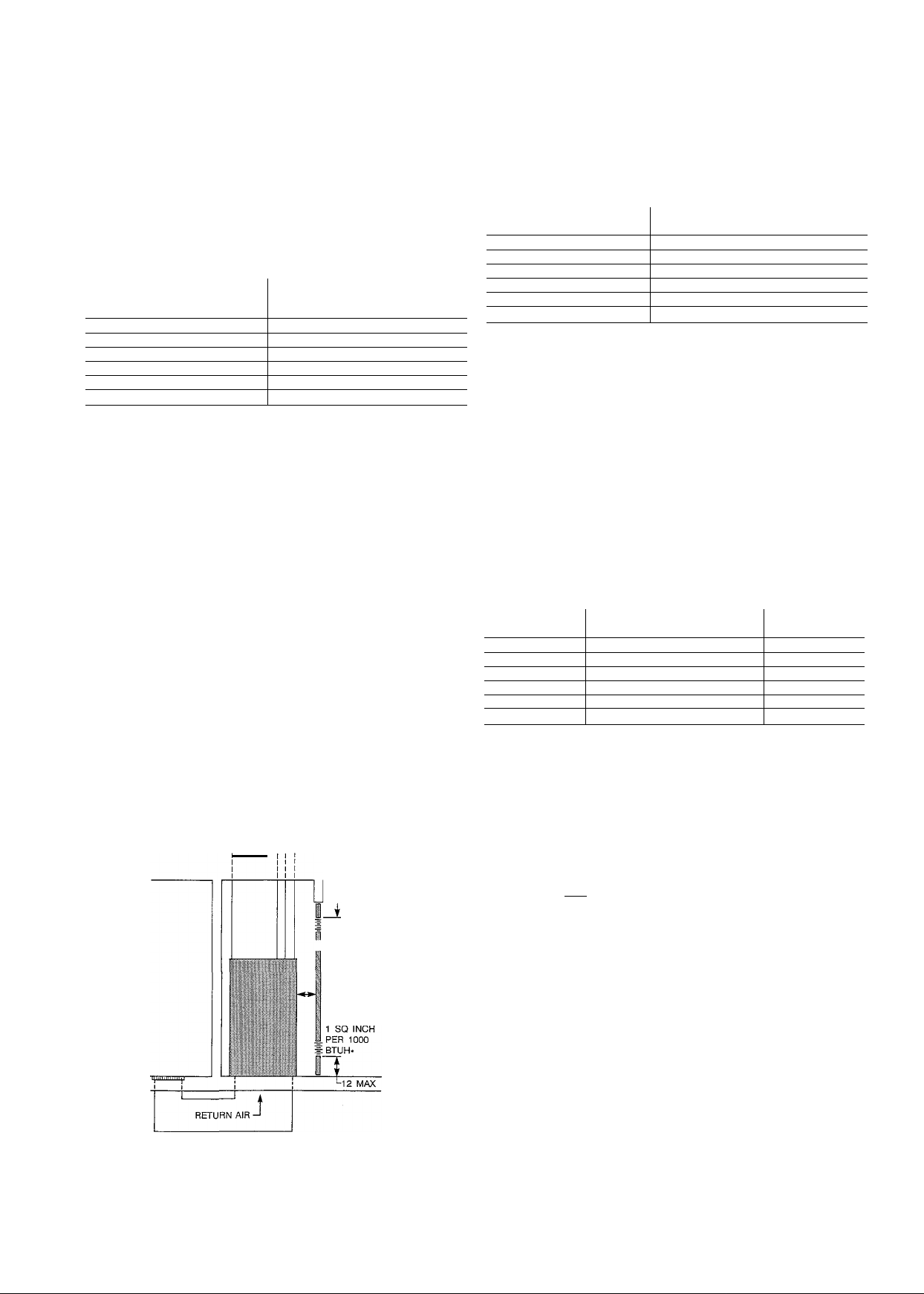
Each opening MUST have at least 1 square in. of free
area per 1000 Btuh of the total input for all equipment
within the confined space, but not less than 100 square
ins. per opening. See Fig. 2.
For Example:
58PAV Furnace
Input Btuh
Free Area per Opening
(square ins.)
44,000 100
66,000 100
88,000 100
110,000 110
132,000
132
154,000 154
44,000 293
66,000
88,000 587
110,000
132,000
154,000
If the unconfined space is of unusually tight construction,
air for combustion and ventilation MUST come from either
the outdoors or spaces freely communicating with the out
doors. Combustion and ventilation openings must be sized
the same as for a confined space. A minimum opening hav
ing a total of not less than 1 square in. per 5000 Btuh of
total input rating for all equipment must be provided.
Return air must not be taken from the room, unless an equal
or greater eimount of air is supplied to the room.
B. Confined Space
A confined space MUST have two permanent openings, one
within 12-ins. of the ceiLing, and the other within 12-ins. of
the floor. See Fig. 2.
NOTE: In deterniining the free area of an opening, the
blocking effect of the louvers, grilles and screens must be
considered. If the free area of a louver or grille design is
unknown, it may be assumed that wood louvers have a 20
percent free area and metal louvers or grilles have a 60 per
cent free area. Screens, when used, must not be smaller than
1/4-in. mesh. Louvers and grilles must be constructed so
they cannot be closed.
The size of the openings depend upon whether the air comes
from inside or outside of the structure.
SUPPLY
AIR
r~Hn
VENT TO ROOF
12 MAX
440
733
880
1026
If the building is of unusually tight construction, a perma
nent opening directly communicating with the outdoors
shall be provided. This opening shall have a minimum free
area of 1 square in. per 5000 Btuh of total input rating for
all equipment in the enclosure.
If the furnace is installed on a raised platform to provide a
return air plenum, and return air is taken directly from the
hallway or space adjacent to the furnace, aU air for combus
tion must come from outdoors.
2. All air from outdoors
a. If combustion air is taken from outdoors through
vertical ducts, the openings and ducts MUST have
at least one square inch of free area per 4000 Btuh
of the total input for aU equipment within the con
fined space. See Fig. 3.
For Example:
58PAV Furnace
input Btuh
44,000
66,000
88,000
110,000
132,000
154,000
Free Area per Opening
(square ins.)
11.0 4
16.5 5
22.0 6
27.5 6
33.0 7
38.5 7
Round Pipe
(ins. dia)
b. If combustion air is taken from the outdoors through
horizontal ducts, the openings and ducts MUST have
at least one square in. of free area per 2000 Btuh of the
1 so INCH PER
4000 BTUH
I'. ".I
T TO ROOF
MAX 12
1 SQ INCH PERT
2000 BTUH
DUCTS
TO ROOF-
SUPPLY D
AIR
A A VENT
^ 1 SQ INCH
PER 1000
I BTUH*
INTERIOR
HEATED
SPACE
-6 MIN
(FRONT)
♦Minimum opening size is 100 square ins.
tMinimum of 3 ins. when type-B vent is used.
Fig. 2
A89012
DUCTS TO
OUTS DE
1 SQ INCH PER
2000 BTUH ^
MAX 12
A
RETURN AIR
USE ANY OF THE FOLLOWING
COMBINATIONS OF OPENINGS:
A&B C&D D&E
j
Fig-3
,^PER 4000
DUCT
TO OUTSIDE
i
2 MAX
1 SQ INCH
BTUH
A89013
Page 4
total input for all equipment within the confined space.
For Example:
58PAV Furnace
Input Btuh
44,000
66,000
88,000 44.0
110,000
132,000 66.0
154,000
Free Area per Opening
(square ins.)
22.0
33.0
55.0
77.0
Round Pipe
(ins. dia)
6
7
8
9
10
10
When ducts are used, they must be of the same cross sec
tional area as the free area of the openings to which they
connect. The minimum dimension of rectangular ducts must
not be less than 3-ins. See Fig. 3.
The front bracket(s) are installed on the bottom front plate
as shown in Fig. 5, once the bottom enclosure has been
removed. Rotate filter supports 180 degrees so filter will
rest on support emd reinstall. (Do not reinstall in 17-1/2-in.
casing.) Install the filter retaining rod (small U-shaped end)
in the rear bracket, and the front of the filter retainer rod as
shown in Fig. 5. Two sets of hardware are needed for fur
naces in 24-1/2-in. casings using one filter for bottom return.
All hardware is provided for filter installation.
A WARNING
Never operate unit without a filter or with filter access
door removed. A failure to follow this warning can
cause a fire, personal injury, or death.
A WARNING
Do not install the furnace on its back; safety control
operation will be adversely affected. Never connect
return-air ducts to the back of the furnace. A failure to
follow this warning can cause a fire, personal injury, or
death.
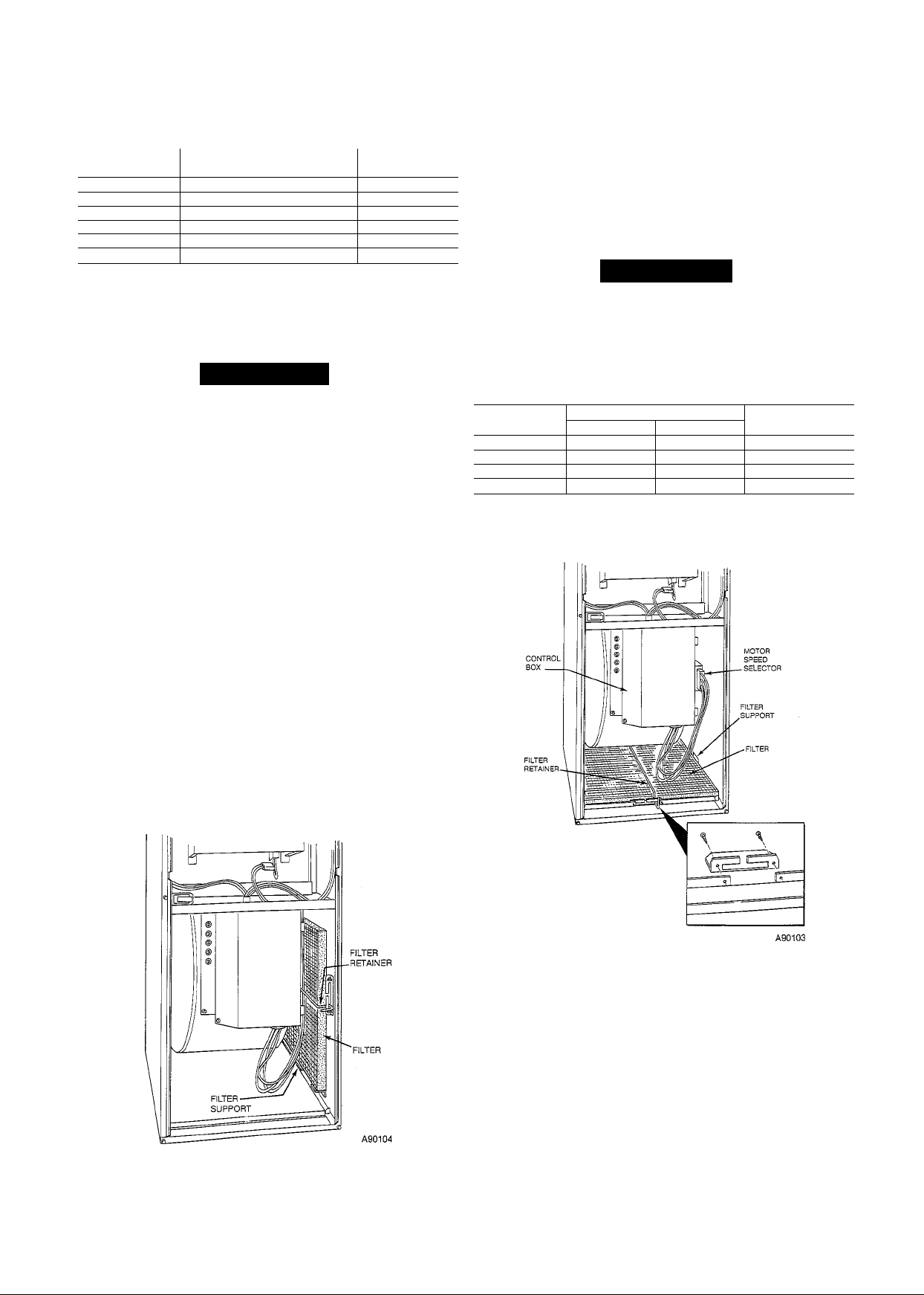
III. FILTER ARRANGEMENT
The factory-supphed filter(s) is shipped in the blower com
partment. Deterrnine location for the filter and move filter
retaining hardware, if necessary, before attaching the
return-air duct. After the return-air duct has been connected
to the furnace, install the filter(s) inside the furnace blower
compartment. See Fig. 4 for side return apphcation and Fig.
5 for bottom return application.
A bottom closure panel is factory-installed in the bottom of
the furnace. When bottom return inlet is desired, remove
and discard the enclosure panel.
Filter retaining brackets, supports, and retainers are fac
tory assembled and shipped installed for side return appUcation, with one set of all required hardware provided. See Fig.
4. For bottom return appHcations, remove the brackets
(front and back) and supports from each side. The back
bracket(s) are installed in the rear of the furnace casing
(dimples are provided to mark mounting screw locations).
Table 3—Filter Information
Furnace
Casing Width
14-3/16
17-1/2
21
24-1/2
*Filter can be field-modified by cutting to the desired size. Aiternate sizes
can be ordered from your Distributor or Deaier.
fFactory provided with the furnace.
Side Return Bottom Return
(1)16x25x1
(1)16x25x1
(1)16x25x1
(2)16x25x1
Fiiter Size* Fiiter
(1)14x25x1t
(1)16x25x1t
(1)20 x 25x1t
(1)24 x 25x1t
Type
Cleanable
Cleanable
Cleanable
Cleanable
Fig. 4—Side Filter Arrangement
Fig. 5—Bottom Filter Arrangement
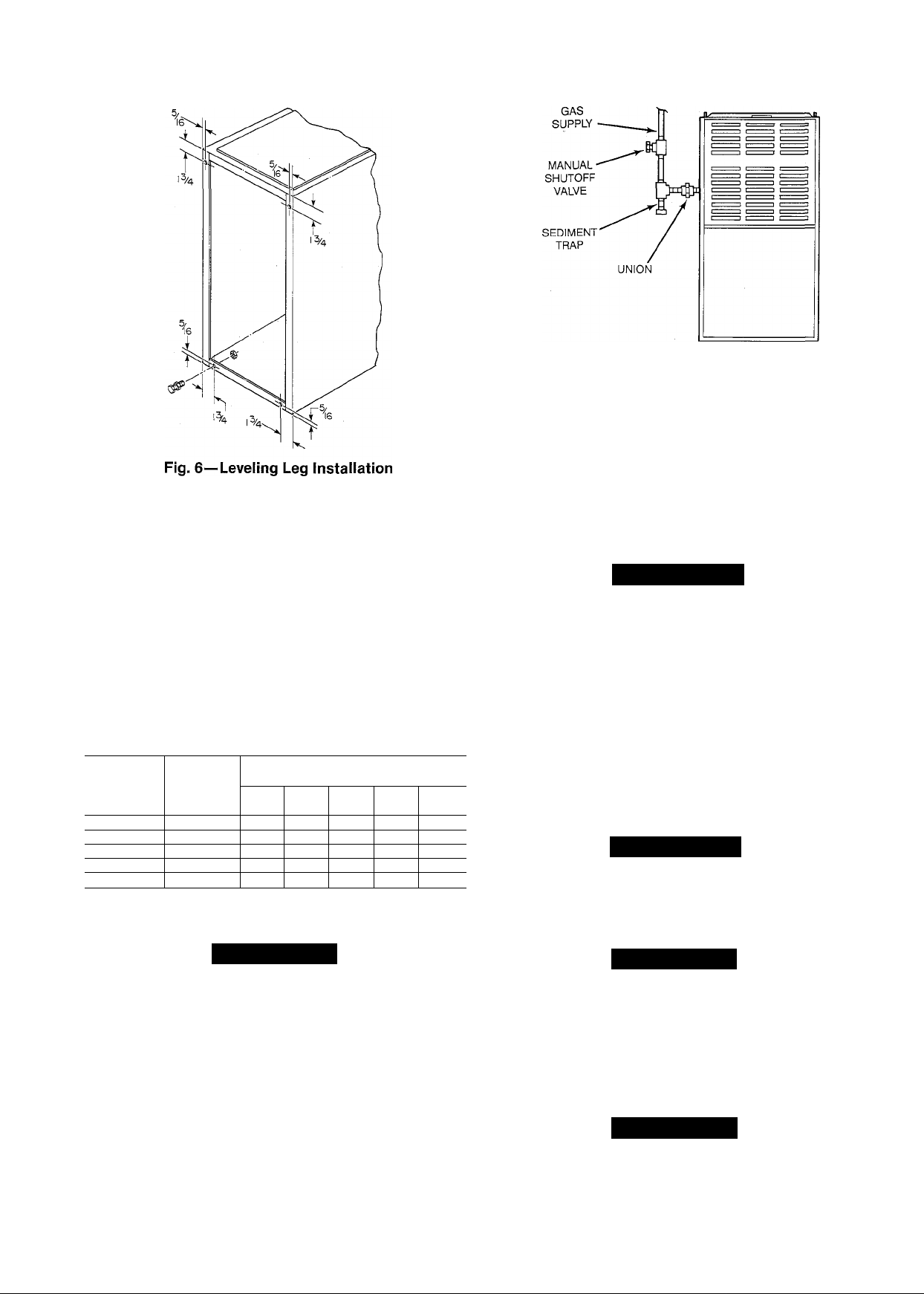
IV. LEVELING LEGS (If Required)
When the furnace is used with side inlet(s), and leveling legs
are required, refer to Fig. 6, and install field-supplied
corrosion-resistant 5/16-in. machine bolts and nuts.
NOTE; The maximum length of the bolt should not exceed
1-1/2 ins.
1. Lay furnace on its back, locate and drill 5/16-in. diame
ter hole in each bottom corner of furnace as shown in
Fig. 6.
2. Install nut on bolt and install bolt and nut in hole.
(Install flat washer if desired.)
Page 5
3. Install another nut on other side of furnace base.
(Install flat washer if desired.)
4. Adjust outside nut to provide desired height, and
tighten inside nut to secure arrangement.
V. GAS PIPING
Gas piping must be installed in accordance with national
and local codes. Refer to the current edition of the National
Fuel Gas Code. Canada installations must be installed in
accordance with CAN/CGA.B149 Installation Codes, and all
authorities having jurisdiction.
The gas supply line should be a separate line running
directly from the gas meter to the furnace, if possible. Refer
to Table 4 for the recommended gas pipe size. Risers must
be used to connect to the furnace and the meter.
Table 4—Maximum Capacity of Pipe*
Nominal
Iron Pipe
Size
Ins.
1/2
3/4
1
1-1/4
1-1/2
*Cubic ft of gas per hour, for gas pressures of 0.5 psig (14 ins. wc) or less,
and a pressure drop of 0.5 in. wc (based on a 0.60 specific gravity gas).
Ref; Table C-4 NFPA 54-1988.
Internal
Diameter
Ins.
0.622 175
0.824
1.049 680
1.380 1400
1.610 2100 1460 1180 990 900
10 20 30 40 50
360 250 200 170
Length of Pipe, Ft
120
465
950 770 660 580
97
82 73
375 320
151
285
Fig. 7—Typical Gas Pipe Arrangement
made, purge the lines and check for leakage with regulated
gas supply pressure.
Install a sediment trap in the riser leading to the furnace.
The trap can be installed by connecting a tee to the riser
leading from the furnace. Connect a capped nipple into the
lower end of the tee. The capped nipple should extend below
the level of the gas controls. See Fig. 7.
Apply joint compound (pipe dope) sparingly and only to the
male threads of each joint. The compound must be resistant
to the action of propane gas.
A WARNING
Never purge a line into a combustion chamber. Never
use matches, candles, flame, or other sources of ignition
for the purpose of checking leakage. Use a soap-andwater solution to check for leakage. A failure to follow
this warning can cause a fire, explosion, personal
injury, or death.
An accessible manual shut-off valve shall be installed
upstream of the furnace gas controls and within 6 ft of the
furnace. A 1/8-in. NPT plugged tapping, accessible for test
gauge connection, must be installed immediately upstream
of the gas supply connection to the furnace and downstream
of the manual shut-off valve. Place ground joint union
between the gas control manifold and the manual shut-off
valve.
A WARNING
Use the proper length of pipes to avoid stress on the
gas control manifold. A failure to follow this warning
can cause a gas leak resulting in a fire, explosion, per
sonal injury, or death.
A CAUTION
If a flexible connector is required or allowed by the
authority having jurisdiction, black iron pipe shall be
installed at the gas valve and extend a minimum of 2ins. outside the furnace casing.
Piping should be pressure-tested in accordance with local
and national plumbing and gas codes before the furnace has
been attached. If the pressure exceeds 0.5 psig (14 in. wc),
the gas supply pipe must be disconnected from the furnace
and capped before the pressure test. If the test pressure is
equal to or less than 0.5 psig (14 in. wc), close the manual
shut-off valve located on the gas valve before the test. It is
recommended that the ground joint union be loosened
before pressure testing. After all connections have been
A CAUTION
Use a backup wrench when connecting the gas pipe to
the furnace to avoid damaging gas controls.
VI. ELECTRICAL CONNECTIONS
A. 115-Volt Wiring
Refer to the unit rating plate or Table 5 for equipment elec
trical requirements. The control system requires an earth
ground for proper operation.
A CAUTION
Do not connect aluminum wire between disconnect
switch and furnace. Use only copper wire.
Page 6

Fig. 8—Heating and Cooling Application Wiring Diagram
Table 5—Electrical Data
Furnace Volts-
Size Hertz-
035-EC
035-GC 115—60—1
055-EC 115—60—1
055-GC 115—60—1
075-GC 115—60—1
075-JC
090-GC
090-JC
090-LC
110-JC 115—60—1
110-LC 115—60—1 127
125-LC 115—60—1
Phase
115—60—1 127
115—60—1 127 104
115—60—1 127
115—60—1 127
115—60—1 127
♦Permissible limits of the voltage range at which the unit will operate
satisfactorily.
tTime-delay fuse is recommended.
ifLength shown is as measured one way along wire path between unit
and service panel for maximum 2% voltage drop.
Operating
Voltage Range Unit Wire Length
Max* Min.*
104 6.7
127 104
127 104 7.1 14
127 104
127 104
104 7.9
104 9.6
104 14.4 12 40
127 104
104 13.3 12 43
127 104 14.0 12 41
Max.
Amps
8.3
8.7
9.0
10.4
10.0
Min.
Max. Wire Max. Fusef or
Gage
14
14
14
14
14
14
14
14
Ftt Ckt Bkr Amps
53 15
43
50
41
40
35
45
37
36 15
HACR-Type
-------------------
FIELD 24-VOLT WIRING
—~ FIELD 115-, 208/230-, 460-VOLT WIRING
15
15
15
15
15
15
15
20
20
20
Make all electrical connections in accordance with the
National ElectriceJ Code ANSI/NFPA 70 and local codes or
ordinances that might apply. For Canadian installations, all
electrical connections must be made in accordance with
CSA C22.1 Canadian Electrical Code, or authorities having
jurisdiction.
A WARNING
The cabinet must have an uninterrupted or unbroken
ground according to National Electrical Code, ANSI/
NFPA 70 and Canadian Electrical Code, CSA C22.1 or
local codes to minimize personal injury if an electrical
fault should occur. This may consist of electrical wire or
conduit approved for electrical ground when installed in
accordance with existing electrical codes. Do not use
gas piping as an electrical ground.
The auxihary junction box can be moved to the right-hand
side of the furnace when a right side power supply is
desired. Remove the two screws holding the auxihary junc
tion box. Mount the junction box on the right-hand side of
the furnace (holes have been predrüled in casing). The
blower door interlock switch must also be moved to the
right side of the furnace due to the length of the wiring har
ness. When moved, tuck the wiring harness behind the clip
provided to keep extra wire lengths out of the way.
NOTE; Proper polarity must be maintained for 115-VAC
wiring. If polarity is incorrect, the microprocessor wiU shut
off gas flow shortly after the completion of ignition trial
period.
Fig. 9—Blower Control Center
B. 24-Volt Wiring
Make field 24-volt connections at the 24-volt terminal strip.
See Fig. 8. Connect terminal Y as shown in Fig. 8 for proper
cooHng operation. Use only AWG No. 18, color coded cop
per thermostat wire.
C. Accessory
1. Electronic air cleaner
Two screw terminals (EAC-1 and EAC-2) are provided
for electronic air cleaner connection. The terminals are
energized with 115-VAC, 1 amp maximum during
blower motor operation.
2. Humidifier
Screw terminals (HUM-1 and C) are provided for 24VAC humidifier connection. The terminals are ener-
, gized with 24-VAC, 0.5 amp maximum during heating
blower motor operation.
VII. VENTING
These instructions are to be used only for 58PAV Furnace
vent systems. These furnaces are equipped with inducedcombustion blowers, and are classified as Category I type
furnaces in accordance with ANSI/A.G.A. Z21.47 Central
Furnace Standards. Category I furnaces use nonpositive,
noncondensing vent systems, and may be connected to Hned
masonry chinmeys sized and installed per the National Fuel
Gas Code.
Page 7

RED
RED
|L1 L2 IgND
(Q
O
C
3
3
(Q
0)
(Q
s
3
GROUND SCREW
LEGEND
ALS 1# AUXILIARY LIMIT SWITCH-MANUAL RESET
ALS 2# AUXILIARY LIMIT SWITCH-AUTOMATIC RESET
BLWR BLOWER MOTOR RELAY
BLWM BLOWER MOTOR
CPU MICROPROCESSOR AND CIRCUITRY
DSS DRAFT SAFEGUARD SWITCH
EAC-1 ELECTRONIC AIR CLEANER CONNECT I ON(115V AC)(1 AMP MAX.)
EAC-2 ELECTRONIC AIR CLEANER CONNECT I ON(COMMON)
FSE FLAME SENSING ELECTRODE
HSI HOT SURFACE IGNITOR (115V AC)
HSIR HOT SURFACE IGNITOR RELAY
HUM-1 24VAC HUMIDIFIER CONNECTION (.5 AMP. MAX.)
HUMR HUMIDIFIER RELAY
ILK BLOWER DOOR INTERLOCK SWITCH
I DM INDUCED DRAFT MOTOR
I DR INDUCED DRAFT RELAY
LO/HI BLOWER MOTOR SPEED CHANGE RELAY
L0T#1 LIMIT OVERTEMPERATURE-MANUAL RESET
L0T#2 LIMIT OVERTEMPERATURE-MANUAL RESET
LS LIMIT SWITCH, OVERTEMPERATURE-AUTO RESET
MGV GAS VALVE-REDUNDANT OPERATORS
MGVR MAIN GAS VALVE RELAY
PL1 11-CIRCUIT EDGE CONNECTOR
PL2 2-CIRCUIT HSI CONNECTOR
PL3 2-CIRCUIT IDM CONNECTOR
(NOTE #1)
PL4 1-CIRCUIT FS CONNECTOR
PL5 5-CIRCUIT BLWM CONNECTOR
PLB 2-ClRCUlT 115V AC CONNECTOR
PRS PRESSURE SWITCH
TRAN TRANSFORMER-115V AC/24V AC
TP1-TP7 TEST POINT (1) THRU (7)
—•
---------
JUNCTION
O UNMARKED TERMINAL
— TERMINAL FACTORY CONNECTOR
MARKED TERMINAL
— — FACTORY WIRING C120V AC)
FACTORY WIRING C24V AC)
- — — FIELD WIRING C120V AC)
' = CONDUCTOR ON PCB1
0 FIELD WIRING SCREW TERM.
^ FIELD GROUND
EQUIP. GROUND
FIELD SPLICE
-) )— PLUG RECEPTACLE
1. COMMON SIDE CSEC-2 AND C3 OF 24V AC TRANSFORMER CONNECTED TO
2. IF ANY OF THE ORIGINAL EQUIPMENT HIRE IS REPLACED USE WIRE
3. INDUCER AND BLOWER MOTORS CONTAIN INTERNAL AUTO-RESET THERMAL
4. BLOWER MOTOR SPEED SELECTIONS ARE FOR AVERAGE CONDITIONS.
5. USE COPPER HIRE ONLY BETWEEN THE DISCONNECT SWITCH AND THE
NOTES;
GROUND THROUGH THIS MOUNTING SCREW.
RATED FOR 105 C, OR EQUIVALENT.
OVERLOAD SWITCHES.
SEE INSTALLATION INSTRUCTIONS FOR DETAILS ON OPTIMUM SPEED
SELECTION.
FURNACE JUNCTION BOX.
310278-401 REV. G
Page 8

However, the venting of this furnace into a hned masonry
chimney could result in the formation of flue gas condensate
due to cold surfaces and oversizing. If condensate is present
in the masonry chimney, a drain must be provided to pre
vent condensate flow into the vent connector and furnace.
Refer to National Fuel Gas Code, Section 7.9 for additional
information on condensate drains. Field experience on
induced-combustion furnaces has shown that venting
through a properly sized Type B-1 vent significantly
reduces the occurrence of vent condensation. Any conden
sate formed is acidic and could cause corrosion of the vent
materials. Therefore, manufacturer suggests (but does not
require) that these furnaces be connected to vent systems
constructed of Tjq)e B-1 vent material.
A. General Instructions
1. This furnace must be installed in accordance with these
instructions, the National Fuel Gas Code NFPA No.
54-1988/ANSI Z223.1-1988, Canadian CAN/CGA.B149
requirements and aU apphcable local codes, and all
authorities having jurisdiction.
2. This furnace must not be connected to a chimney flue
servicing a separate appliance designed to burn solid
fuel.
3. Never cormect this furnace to a chimney serving a fire
place, unless the fireplace opening is permanently
sealed off.
4. The recommended vent system for this furnace is con
structed of Type B-1 double-waU vent pipe (UL or ULC
listed). A minimum 1-in. clearance is required between
Type B-1 vent and combustible materials.
5. It may be necessary to add insulation to Type B-1
double-wall vent and to single-wall vent connector, if
allowed by local codes, in some applications. When
insulation is required it must be at least 1-in. thick
fiberglass with foil backing. Using permanent foil tape,
attach insulation to vent pipe. Both the foil tape and
fiberglass insulation must be suitable for temperatures
up to 350 F.
6. Insulation must be added to any vent connector which
will be exposed to ambient temperatures of 30 degrees
Fahrenheit or less, especially any application using
single-wall vent pipe as a connector.
Add insulation to Type B-1 vent in some applications
as indicated with an asterisk (*) in appropriate tables.
Do not insulate vent pipe exposed to outdoor weather
conditions, (i.e. above roof lines).
7. Do not use a vent size smaller or larger than the size
shown in Tables 6 thru 14.
8. If this furnace is connected to a Hned, masonry chim
ney, the chimney must be sized and installed according
to the provisions of the National Fuel Gas Code, or
Canadian CAN/CGA.B149 requirements. Vent connec
tors from the furnace to the chimney should be made
with insulated single-wall vent pipe or Type B-1 vent
pipe. Insulate per Section A.5 when required.
9. Installation of the vent pipe should be as directly as
possible, with a minimum number of turns or elbows.
10. Maintain a minimum of 1/4-in. upward slope per Hnear
ft on all horizontal vent pipe runs.
11. Rigidly support the vent pipe every 5 ft or less with
hangers or straps to ensure that there will be no move
ment after installation.
12. No portion of the vent system shall extend into, or pass
through, any circulation air duct or plenum.
13. The Type B-1 vent system shall terminate above the
roof surface per the National Fuel Gas Code or CAN/
CGA.B149 requirements, emd shall include a UL or
ULC Hsted vent cap or roof assembly, unless prohib
ited by local codes.
14. This furnace may be common vented with another fur
nace or other Hsted gas-fired appHances. Total input
rates of aU appHances wiU determine the vent size. See
Sections C and D for additional information.
15. If a common vent system becomes blocked, the furnace
win be shut off by the draft safeguard switch located
on the inducer assembly.
A WARNING
Do not bsqjass the draft safeguard switch, as an unsafe
condition exists which must be corrected. A failure to
foUow this warning could result in a buildup of carbon
monoxide and lead to personal injury or death.
16. All vent pipe passing through floors, ceiHngs, and waUs
must be instaUed with the proper clearances from com
bustible material, and be fire-stopped according to the
National Fuel Gas Code requirements and Canadian
Standards CAN/CGA.B149.
17. In replacement instaUation, where an existing vent sys
tem may be used, the vent system must be inspected
for condition, size, type of vent material, and height to
meet the requirements in these instructions. If the
existing vent system is larger than shown in vent
Tables 6 thru 14, the vent system wfll be oversized, and
condensation cem occur causing corrosion of the vent
system. InstaUation of a replacement vent system may
be required.
18. When removing an existing furnace from a common
vent system, the vent system is likely to be oversized
for the remaining appHances. Refer to Section E for
additional information.
19. Vent connectors or vents servicing Category I appH
ances shall not be connected into any portion of
mechanical draft systems operating under positive
pressure.
20. For instaUation of vent systems not covered in Sec
tions B, C, and D, or for vent systems with length/
height beyond that shown, refer to the National Fuel
Gas Code for information. FoUowing the National Fuel
Gas code requirements wiU provide for an acceptable
vent system and proper operation of the furnace.
B. Venting Tables For Dedicated Vent System (one
58PAV Furnace)
The foUowing tables eire used to size the vent system for a
58PAV Furnace when using a dedicated vent system. The
information shown in these tables indicate the maximum
horizontal length of vent pipe aUowed for a vent system of a
set height and number of elbows. Some tables include infor
mation for vent lengths aUowed when insulation is added to
the vent connector and the vent. See Tables 6 thru 11 and
Fig. 11.
1. When single-waU vent pipe is used for vent connector,
it must be insulated as indicated in venting table data
marked with an asterisk {*). Insulation must be added
as specified in Sections A.5 and A.6.
Insulation should be added to any single-waU vent pipe
used as a vent connector, especiaUy those appHcations
with long (over 5 ft) vent connector runs.
2. Each table is for a specific size of furnace depending
upon the rated furnace input.
Page 9

Fig. 11 —Dedicated Vent (Typical)
Table 6—Dedicated Type B-1 Vent For
58PAV035-EC and GC Maximum
Horizontal Length Allowed (Ft)
Height Number of 90° Elbows
5 0
10 0 10
15 0
20 0 6
20* 0
25 0 NA NA 2
25* 0
30 NA NA NA NA
30* 0
5 0 5
10 0 4
15 0 NA NA NA
15* 0
20 NA NA NA NA
20* 0
25 NA
25* 0
30 NA NA
30* 0
0 1 2 3
5 5
10
10 10 10
6
20* 20* 20* 20*
25* 25* 25* 25*
30* 30* 30* 30*
5
4
15* 15*
20* 20*
NA NA
25* 25* 25*
NA
30* 30* 30* 30*
Table 7—Dedicated Type B-1 Vent For
58PAV055-EC and GC Maximum
Horizontal Length Allowed (Ft)
Height Number of 90° Elbows
5 0 5
10 0 10 10
15 0
20 0 20
25 0
25*
30 0
30*
5 0
10
15 0
20 0
20* 0
25
25* 0
30
30* 0
NA—Not allowed. Condensation
could occur.
♦Insulated with 1-in.
0 1
0 25*.
0
0 10 10 10 10
0 8 8 8
0 4 4 4
of foil-backed insulation per Section A.5.
2
NA
15 15
20
18 16
25*
14 14
30* 30* 30*
5 5
15 15
12 12
20* 20*
25* 25* 25*
30* 30* 30* 30*
or positive pressure in vent system
4
NA
10
10
10 10
6
NA NA
5
4
NA NA
15*
15*
NA NA
20*
20*
NA
NA
25* 25*
NA
NA
3
4
NA
NA NA
10
NA
15
15
20
20 20
16
16
25* 25*
14
14
30* 30*
5
NA
15
15
12
12
20*
20*
25* 25*
4
6
2 2
5
4
NA
15
16
14
NA
10
15
12
20*
8 8
4
30*
5
NA
10
6
20*
25*
30*
5
4
15*
20*
NA
NA
30*
5
25*
4
A89017
Vent
Pipe
4-lN.
DIAMETER
5-IN.
DIAMETER
Vent
Pipe
4-IN.
DIAMETER
5-IN.
DIAMETER
3. For all applications, the horizontal length of vent and
vent connector must not exceed the vertical height of
the vent system.
4. Addition of insulation to vent connector and vent
allows for longer horizontal runs in certain applications
as indicated with an asterisk (*) in appropriate tables.
5. When Type B-1 vent pipe is used for vent connector, it
must be insulated as indicated with an asterisk (*) in
the vent tables.
Table 8—Dedicated Type B-1 Vent For
58PAV075-GC and JC Maximum
Horizontal Length Allowed (Ft)
Height
5
10 0 10 NA NA NA NA
15 0 15
20 0 20
25
30 0 30
5 0 5
10
15 0
20 0 20
25
30
NA—Not allowed. Condensation or positive pressure In vent system
could occur.
♦Insulated with 1-in. of foil-backed Insulation per Section A.5.
Number of 90° Elbows
0 1 2 3 4 5
NA NA
0
25 25
0
10 10 10 10
15 15 15 15
0
22 22
0
20
NA
NA
15 NA NA
15
20 16 10
20
25
30 30 30
30
5
20 20 20
20
22
20 20 20
20
NA NA
25
5 NA
22
20
NA
10
15
22
Vent
Pipe
4-IN.
DIAMETER
5-IN.
DIAMETER
Table 9—Dedicated Type B-1 Vent For
58PAV090-GC, JC, and LC Maximum
Horizontal Length Allowed (Ft)
Height Number of 90° Elbows
0
1 2 3 4 5
5
10
15 0
NA
NA NA
NA
10 NA NA NA NA
15 8
20 0 20
25 0
30
5
10 0
15
20
25
30 0
NA—Not allowed. Condensation or positive pressure In vent system
could occur.
25 25
0
30
0
5 2 NA NA NA
10 10
0
15 15 15 15 15
0
20 20
0
25
30 30
NA
16 12 4
20
24
30 28 22
30
10
20
25 25 25
25
30
6
NA
NA
NA NA
12
18
NA
NA
20 20
30
30
Vent
Pipe
4-IN.
DIAMETER
5-IN.
DIAMETER
Table 10—Dedicated Type B-1 Vent For
58PAV110-JC and LC Maximum Horizontal
Length Allowed (Ft)
Height
5
10 0
15 0
20
25 0
30
5 0
10 0 10
15 0
20 0
25 0
30 0
NA—Not allowed. Condensation
could occur.
Number of 90° Elbows
0 1
NA
NA
10
15
0
20
25
0
30
5
15
20
25 25 25 25
30
2 3 4
NA NA NA
NA
6
15
15
20 20 20 20
25
25
30
30
4 NA
5
10 10 10
15
15
20 20
20
30
30
or positive pressure in vent system
NA
15 6
25 25
30 30
15 15
30
5
NA
NA
NA
10
20
25
30
Vent
Pipe
5-IN.
DIAMETER
6-IN.
DIAMETER
Page 10

Table 11—Dedicated Type B-1 Vent For
58PAV125-LC Maximum
Horizontal Length Allowed (Ft)
Height Number of 90° Elbows Vent
5 NA
NA
10 0 10 10
15 0
15
20 0 20 20 20 20 20
25
30
5
0 25 25
0 30
0 5
10 0 10 10 10 10 10
15 0 15 15 15 15 15
20 0 20 20 20 20 20
25
0 25 25 25 25 25
30 0 30 30 30 30 30
NA—Not allowed. Condensation
could occur.
C. Venting Tables For Common Vented Furnaces (two,
three, or four 58PAV Furnaces)
The following information refers to installations where two,
three, or four 58PAV Furnaces are common vented into a
single vent system. Do not connect more than four 58PAV
Furnaces into a common vent system. See Fig. 12. Table 12
data is for a vent system where all the furnaces are the same
size. For common vent apphcations using various sizes of
58PAV Furnaces, contact your Distributor or Dealer for
more information.
To determine the proper common vent size, total the heat
input of all the apphemces to be connected to the vent sys
tem, next select the smallest vent size which wUl meet that
rated input.
NOTE: A listed single-wall to T3?pe B-1 vent adaptor is
required to connect single-wall vent connectors to the com
mon vent.
1. Vent connectors should be as short and direct as possi
ble, and should be made of Type B-1 double-wall vent
pipe or insulated single-wall vent pipe.
2. Vent connectors shall be sized using dedicated venting
table in Section B of this publication. The length of hor
izontal run used in the vent connector and vent must
never exceed the height of the common vent.
3 4
NA NA NA
NA NA
15 15 15
25 25
30 30 30
5 5 NA NA
or positive pressure in vent system
5
NA
NA
15
25
30
FURNACE
Pipe0 1 2
5-IN.
DIAMETER
6-IN.
DIAMETER
A89018
Fig. 12—Common Venting Of Furnaces
(Typicai installation)
Table 12—Common Venting Of Furnaces
(Typicai instaliation)
58PAV
Size
035-EC
or
035-GC
055-EC
or
055-GC
075-GC
or
075-JC
090-GC,
090-JC,
or
090-LC
110-JC
or
110-LC
of
Furnaces
2
3
4
2
3
4 14
2
3 14 40 7
4 14
2 14
3 10 40 8
4 10 40 9
2 14 40 7
3
4
Common Vent Height (Ft)
Minimum Maximum*
8 40
6 40 6
14
8 40 6
14 40
8 40 7
14 40 5
8 40 6
14 40 6
8 40
10 40 8
10 40 6
8 40
8 40 8
10 40 9
10 40 7
8 40 9
10 40 10
8 40 8
10 40 9
8 40 10
16 40 9
10
40 5
40
40 8
40 6
40 10
125-LC 2 10 40 7
Number
6 40. 8
3
4 18
*For applications requiring
tion other than specified,
information.
6
14
8 40 9
8 40 10
14
10 40 10
vent heights greater than 40 ft, or
contact your Distributor or Dealer
40 9
40 8
40 8
40 9
3. Vent connectors should be spaced at least 1 ft
when entering the common vent system.
4. Insulated vent connectors may be required for certain
applications. See Sections A.5. and A.6. for additional
information.
5. For multi-story installation, refer to Appendix G of
National Fuel Gas Code or Canadian standards CAN/
CGA.B149 for additional information in sizing the com
mon vent. Individual vent connectors should be sized
per the dedicated appliemce tables shown in Section B.
D. Venting Tables For Common Vents (One 58PAV
Furnace and Gas Hot Water Heater)
The information in this section refers to the installation of a
common vent serving a 58PAV Furnace and a gas hot water
heater. Tables 13 and 14 use typical hot water heater input
rates of 40,000 Btuh or 50,000 Btuh. Refer to the water
heater rating plate for input ratings of the installed
equipment.
1. Size common vent and vent connector lengths using
Tables 13 and 14.
2. Vent connectors should be as short and direct as
possible.
3. Size gas water heater vent connector per National Fuel
Vent
Dia
(Ins.)
5
6
7
7
7
combina-
for more
apart
10
Page 11

Fig. 13—Common Vent With Water Heater
(Typical Installation)
Table 13—Common Vent (With No Lateral Run)
Furnace and Water Heater (No Horizontal)
58PAV
Size
035-ECt
Connector
Length (Ft)
5
or
Vent
035-GCt
055-ECt
10 12
15 12
5 18
or
055-GCt
075-GCt
10 20
15 20
5 10
or
075-JCt
090-GCt,
10 10
15 10
5
090-JCt,
or
10 14
090-LCt
15
110-JCÍ
5 10
or
110-иСф
10 10
15 10
125-LCt 5 8
10
15
Common Vent Height (Ft)
Minimum
12
6
6
6
8
8
8
5
5
5
14
6
6
14
6
5
5
5
6
6
8
6
■ 6
10
6
6
Maximum*
30
30 5
30
24
26 4
16
30 4
30 5
30
30 5
30 4
30 5
30
30
30
30 6
30 5
30 6
30
30
30 5
30 6
30
30
30
30
30
30 7
30
30
30 6
30
30 8
30
30 7
30
30 6
30 7
30 8
*For applications requiring vent heights greater than 30 ft, contact your
Distributor/Dealer for more information,
flnstalied with a 40,000 Btuh gas-fired water heater—typical size.
^Installed with a 50,000 Btuh gas-fired water heater—typical size.
Common
Vent
Dia
(ins.)
A89019
4
4
5
5
4
5
6
5
5
6
5
6
6
7
6
6
7
7
6
8
Gas Code. The 58PAV Furnace vent connector is sized
per the tables in Section B of this publication to deter
mine allowable lengths, number of elbows, and insula
tion requirements. The allowable vent connector length
for the furnace cannot exceed 15 ft for any common
vent installation or application, as shown in Tables 13
and 14.
4. Insulated vents and vent connectors may be required
for certain applications. See Table 14. When insulation
is required, it must be installed as indicated in Sections
A.5. and A.6.
5. If the vent connector is exposed to ambient tempera
tures of 30 degrees Fahrenheit or less, it must be insu
lated, as indicated per Sections A.5. and A.6.
6. The vent connectors must be spaced within 3 ft of each
other (3-ft rise).
7. Where possible, locate the vent closer to or directly
over the smaller appliance connector.
8. For multi-story installation, refer to Appendix G of
National Fuel Gas Code or Canadian standards CAN/
CGA.B149 for additional information to size the com
mon vent. Individual vent connector for the furnace
should be sized per single apphemce tables found in Sec-
Table 14—Common Vent (With 10 Ft Max. Lateral
Run) Furnace and Water Heater
Vent and
58PAV
Size
035-ECt
035-GCt
055-ECt
055-GCt
075-GCt
075-JCt
090-GCt,
090-JCt,
090-LCt
110-JCt
110-LCt
125-LCt 5
Connector
Length (Ft)
or
or
or
or
or
Vent
10
15
10
15
10
15
10
15
10
15
10
15
Vent Conn
Insulation
Required
5
5
5
5
5
Common Vent Height (Ft)
—
yes 6
—
yes 6
—
yes 6
—
yes 8
—
yes
—
yes 8
—
—
Minimum
NA
10
—
—
—
—
—
—
— 14
_
_
—
—
—
—
—
—
—
—
—
—
—
—
—
10
10 30 6
10
Maximum*
8
8 14 5
NA 5
8
10 30 5
8 30
10 22 5
10
5
5
10
5
14 30 5
6
14
6
6 30
10
5
5
5 30
10
8 30
6
8
6
10 30 6
8
6 30 8
30
30
30 8
30
*For applications requiring vent heights greater than 30 ft, contact your
Distributor/Dealer for more information,
tinstalled with a 40,000 Btuh gas-fired water heater—typical size,
llnstalled with a 50,000 Btuh gas-fired water heater—typical size.
Common
Vent
Dia
(Ins.)
22
30
30
30
30
30
30
30
30
30
30 6
30
30 6
30
30 5
30
30 5
30
30
30
30
30
30
5
5
5
6
5
5
6
6
6
6
7
6
7
7
6
7
8
6
7
7
11
Page 12

tion B. The water heater vent connector must be sized
per the National Fuel Gas Code.
E. Removal of Existing Furnaces From Common Vent
Systems
1. These steps shall be followed with each appliance
remaining connected to the common vent system
placed in operation, while the other appliances remain
ing connected to the common vent system are not in
operation.
2. Seal any unused openings in the common vent system.
3. Visually inspect the vent system for proper size and
horizontal pitch, and determine there is no blockage or
restriction, leakage, corrosion, and other deficiencies
which could cause an unsafe condition.
4. Insofar as practical, close all building doors and win
dows and all doors between the space in which the
appliances remaining connected to the common vent
system are located and other spaces of the building.
Turn on clothes dryers and emy appliance not con
nected to the common vent system. Turn on any
exhaust fans, such as range hoods and bathroom
exhausts, so they operate at maximum speed. Do
not operate a summer exhaust fan. Close fireplace
dampers.
5. Follow the lighting instructions and place the apph-
ance in operation. Adjust the thermostat so appliance
will operate continuously.
6. Test for flue gas spUlage at the drafthood rehef open
ing (or draft safeguard tube opening) after 5 minutes of
main burner operation. Use the fleime of a match or
candle, or smoke from a cigarette, etc.
7. After it has been determined that each appliance
remaining connected to the common vent system
properly vents when tested as above, return doors, win
dows, exhaust fans, fireplace dampers, any other gasbuming appliances to their previous condition of use.
8. If improper venting is observed during any of the
above tests, the common vent system must be cor
rected. The vent system or vent connectors may need
to be resized. Resize any 58PAV Furnaces vent system
according to these instructions. For any other appli
ances when resizing vent systems or vent connectors,
the system or connector must be sized to approach the
rninimum size as determined using the appropriate
table found in Appendix G of the National Fuel Gas
Code, ANSI Z223.1 or Section 5 of CAN/CGA.B149 for
Canadian installations.
VIII. STARTUP, ADJUSTMENT, AND SAFETY CHECK
A. General
The furnace must have a 115-VAC power supply properly
connected and grounded. Proper polarity must be main
tained for proper operation. Thermostat wire connections at
R, W, C, and Y must be made at the 24-volt terminal block
on the control board. The gas service pressure must not
exceed 0.5 psig (14 in. wc), but must be no less than 0.16
psig (4.5 in. wc).
Before operating the furnace, check each manual reset
switch for continuity. If necessary, press the button to reset
the switch.
The blower compartment door must be in place to complete
the 115-VAC circuit to the furnace.
A CAUTION
This furnace is equipped with a manual reset limit
switch in the gas control area. The switch will open and
shutoff power to the gas valve if a flame rollout or over
heating condition occurs in the gas control area. Do not
bypass the switch. Correct inadequate combustion air
supply problem and reset the switch.
B. Sequence of Operation
Using the schematic diagram. Fig. 10, follow the sequence
of operation through the different modes. This furnace has a
new and unique control system, therefore, read and follow
the wiring diagram very carefully.
1. Heating mode
The waU thermostat “calls for heat,” closing the R and
W circuit. The furnace control performs a selfcheck,
verifies the pressure switch contacts are open, and
starts the inducer motor.
a. Prepurge period—As the inducer motor comes up to
speed, the pressure switch contacts close to begin a
15 second prepurge period.
b. Ignitor warm up—At the end of the prepurge
period, the ignitor is energized for a 17 second igni
tor warm-up period. If ignition is not established
during the first cycle, the next warm-up period is
increased to 45 seconds. AH subsequent ignition
cycles wiU be 45 seconds, or until the 115-VAC
power supply is interrupted. By interrupting the
115-VAC power supply, the warm-up period is auto
matically reset to 17 seconds.
c. Ignition sequence—When the ignitor warm-up
period is completed the gas valve opens, permitting
gas flow to the burners where it is ignited. After 5
seconds, the ignitor is deenergized and a 2 second
flame sensing period begins.
d. Flame sensing—When burner flame is sensed, the
control begins the blower “on” delay period and
continues holding the gas valve open. If burner
flame is not sensed, the control will close the gas
valve, and control wUl repeat ignition cycle.
e. Blower on delay—60 seconds after burner flame is
proven, the blower motor is energized on heating
speed. Simultaneously, the humidifier and electronic
air cleaner terminals (HUM-1 and C for humidifier,
EAC-1 and EAC-2 for electronic air cleaner) are
energized.
f. Blower off delay—When the thermostat is satisfied,
the circuit between R and W is broken, deenergizing
the gas valve stopping gas flow to the burners. The
blower motor, humidifier, and air cleaner wUl remain
energized 90, 135, 180, or 225 seconds (depending
on the blower off-time selection). The furnace is
factory-set for a 135-second blower off delay.
g. Post purge—The inducer motor will remain ener
gized 5 seconds after the burners are extinguished.
2. Cooling mode
The thermostat “calls for cooling” closing R-G and R-Y
circuits. The R-Y circuit starts the outdoor condensing
unit, and the combined R-Y and R-G circuit starts the
furnace blower motor on cooling speed. The electronic
air cleaner EAC terminals are energized with 115-VAC
when the blower is operating on cooling speed.
When the thermostat is satisfied, R-G and R-Y circuits
are broken. The furnace blower wUl continue operating
on cooling speed for an additional 90 seconds.
12
Page 13

3. Continuous blower mode
When the R-G circuit is made, the blower motor will
operate on heating speed. During a call for heat, the
blower will stop, allowing the furnace heat exchangers
to heat up more quickly.
The blower will revert to continuous operation after the
heating cycle is completed.
When the thermostat “calls for cooling,” the blower
wiU operate on cooling speed. When the thermostat is
satisfied, the blower wiU operate an additional 90 sec
onds before reverting back to continuous operation on
heating speed.
4. Heat pump mode
When instaUed with a heat pump, the furnace control
automaticaUy changes the timing sequence to avoid
long blower off time during demand defrost cycles.
When the W-Y or W-Y-G thermostat inputs are
received together, the control wiU change the blower to
heating speed or start the blower if it was off, and
begin a heating cycle. The blower wiU remain on until
the end of the purge period, then shut off until the end
of the ignition warm up and trial for ignition periods (a
total of 24 seconds). The blower wUl then come back on
at heating speed.
When the W input signal disappears, the control wiU
begin the normal inducer post-purge period and the
blower wUl change to cooling speed after a one second
delay. If the W-Y-G signals should disappear together,
the blower wiU remain on for the selected heating
blower off delay period, and the inducer wUl go through
its normal post-pm-ge period. If the W-Y inputs should
disappear, leaving the G signal input, the control wUl
go into continuous blower and the inducer wiU remain
on for the normal post-purge period.
While in heat pump mode, the control will use only the
17 second ignition warm-up period, and will not use the
45 second period at all. The control wUl initiate a 90
second blower only on delay before starting another
heat pump cycle, if there is a power interruption. Any
time the control senses false flame, the control wUl lock
out of the heating mode. This occurs because the con
trol cannot sense the W input due to the false flame
signal, and as a result sees only the Y input and goes
into cooling mode blower off delay. AU other control
functions remain in standard format.
C. Startup Procedures
1. Self test—The furnace features a self-test system to
help diagnose a system problem in the case of a compo
nent faUure. Two test pins (ST-1 and ST-2) are located
in the lower left-hand corner of the control board as
shown in Fig. 9. To initiate the self-test procedure,
momentarUy short across the two pins.
NOTE: The self-test feature wUl not operate if the con
trol board is receiving any thermostat signals.
The self-test sequence is as foUows:
a. The furnace control wUl check itself and then oper
ate the inducer motor for 10 seconds, then off.
b. The hot surface ignitor is then energized for 15 sec
onds, then off.
c. The humidifier relay is then energized for 10 sec
onds, then off.
d. The blower motor wUl operate on cooling speed for
10 seconds, then off.
e. The blower motor wUl operate on heating speed for
10 seconds, then off.
2. Purge gas lines—After aU connections have been made,
purge the lines and check for leaks.
A WARNING
Never purge a line into a combustion chamber. Never
use matches, candles, flame or other sources of ignition
for the purpose of checking leakage. Use a soap-andwater solution to check for leakage. A faUure to foUow
this warning can cause a fire, explosion, personal
injury, or death.
3. To operate furnace, foUow procedures on operating
instructions label attached to furnace.
4. With furnace operating, set thermostat below room
temperature and observe that furnace goes off. Set
thermostat above room temperature and observe that
furnace restarts.
D. Adjustments
1. Set gas input rate.
There are two methods of adjusting the gas input rate.
The preferred method is by using Table 15 and step a.
The second method is by clocking the gas meter and
step b.
The gas valve regulator has been nominaUy-set at 3.5
ins. wc for natural gas. When adjusting input rate, do
not set manifold pressure above 3.8 or below 3.2 ins.
wc.
a. Check gas input rate using Table 15.
(1.) Obtain average yearly heat value for local gas
supply.
(2.) Obtain average yearly specific gravity for local
gas supply.
(3.) Verify furnace model. Table 15 can only be used
for Model 58PAV Furnaces.
(4.) Check and verify orifice size in furnace.
NEVER ASSUME THE ORIFICE SIZE,
ALWAYS CHECK AND VERIFY.
(5.) Find natural gas heat value and specific gravity
in Table 15.
(6.) FoUow heat value and specific gravity fines to
point of intersection. Find orifice size and mani
fold pressure settings for proper operation at
given natural gas conditions.
EXAMPLE: '
Heat value 1070 Btu/cu ft
Specific gravity 0.58
Therefore; Orifice No. 44*
Manifold pressure 3.3 ins. wc
*The furnace is shipped with No. 43 orifices. Therefore, in
this example aU main burner orifices must be changed and
niamfold pressure must be adjusted.
(7.) Proceed to step c to adjust manifold pressure.
b. Check gas input rate by clocking gas meter.
(1.) Obtain average yearly heat value for local gas
supply.
(2.) Check and verify orifice size in furnace.
NEVER ASSUME THE ORIFICE SIZE,
ALWAYS CHECK AND VERIFY.
A CAUTION
DO NOT redrill burner orifices. Improper drilling
(burrs, out of round, etc.) can cause excessive burner
operating noise and misdirection of burner flames. This
could result in flame impingment on burners and heat
exchanger surfaces, leading to potential failures.
13
Page 14

(3.) Turn off all gas appliances £ind pUots.
(4.) Start furnace and let run for 3 minutes.
(5.) Measure time (in seconds) for gas meter to com
plete one revolution.
(6.) Refer to Table 16 for cubic ft of gas per hour.
(7.) Multiply gas rate cu ft/hr x heating value (Btu/
cu ft).
"Example:
Btu heating input = Btu/cu ft times cu ft/hr
Heating value of gas = 1070 Btu/cu ft
Time for one revolution of 2-cu/ft dial = 72 seconds
Gas rate = 100x1070 = 107,000 Btuh
(8.) Measured gas input should not exceed gas
input on unit rating plate.
(9.) Proceed to step c to adjust manifold pressure,
c. Adjust gas input.
(1.) Remove regulator adjustment seal cap. See
Fig. 14.
(2.) Turn adjusting screw counterclockwise to
decrease input. Turn screw clockwise to
increase input. DO NOT set manifold pressure
less than 3.2 or more than 3.8 maximum ins. wc
for natural gas. Make any major adjustments
by changing meiin burner orifices.
(3.) When correct input is obtained, replace regula
tor seal cap. Main burner ñame should be clear
blue, almost transparent. See Fig. 15.
BURNER FLAME
MANIFOLD
PRESSURE TAP
Fig. 14—Redundant Automatic Gas Control Valve
Table 15—Model 58PAV Orifice Size and Manifold Pressure For Correct Input Rate
(Tabulated data based on altitude up to 2000 ft and 22,000 Btuh per burner.)
Gas
Heat
Value
(Btu/cu ft)
860
875
890
905
920
935
950
965
980
995
1010
1025
1040
1055
1070
1085
1100
Orf
No.
41
42
42
42
42
43
“43“
43
44
43
44
44
“4^
'45~'
0.56
MnfId
Press
3.2
3.6
3.4
3.3
3.2
3.8
3.7
3.6
3.4
3.8
3.3
3.7
3.2
3.6
3.5
3.4
3.3
3.2
3.8
3.7
Orf
No.
41
42
41
42
42
42
42
■ 4^
■ 4^“
"4^
44
43
44
43
44
43
44
44
44
0.58
MnfId
Press
3.3
3.7
3.2
3.6
3.4
3.3
3.2
"as"
3.7
3.6
3.5
“ as"
3.4
3.7
3.3
3.6
3.2
3.5
■aT“
3.3
3,2
3.8
Orf
No.
41
42
40
41
42
41
42
42
42
42
43
43
43
43
44
43
44
43
44
43
44
44
44
44
0.60
MnfId
Press
SPECIFIC GRAVITY OF NATURAL GAS
0.62
Orf
No.
41
3.4
40
3.8
3.2
41
3.3
42
3.7
40
41
3.2
42
3.6
41
3.4
42
42
3.3
42
3.2
42
3.8
43
43
3.6
43
3.5
43
3.8
3.4
~4^
3.7
3.3
44
3.6
43
3.2
44
3.5
43
44
3.4
44
3.3
44
3.2
MnfId
Press
3.5
3.3
3.4
3.8
3.2
3.3
3.7
3.2
3.6
3.4
3.3
3.2
3.8
3.7
3.6
3.5
“aA"
3.7
3.3
3.6
3.2
3.5
3.4
3.4
Orf
No.
41
39
40
41
40
41
42
41
42
41
42
42
42
42
43
43
43
43
43
44
43
44
43
44
44
0.64
MnfId
Press
3.7
3.2
3.4
3.5
3.3
3.4
3.8
3.3
3.7
3.2
3.5
3.4
3.3
3.2
3.8
3.7
3.6
3.5
3.4
3.8
3.3
3.7
3.2
3.6
3.5
Orf
No.
41
39
40
41
39
40
41
40
41
42
41
42
41
42
42
42
42
43
43
43
43
44
43
44
43
44
0.66
MnfId
Press
3.8
3.3
3.5
3.6
3.2
3.4
3.5
3.2
3.4
3.8
3.3
3.7
3.2
3.5
3.4
3.3
3.2
3.8
3.7
3.6
3.5
3.4
3.8
3.3
3.7
3.2
3.6
Orf
No.
39
40
41
39
40
41
40
41
40
41
42
41
42
41
42
42
42
42
43
43
43
43
43
44
43
44
43
0.68
MnfId
Press
3.4
3.6
3.8
3.3
3.5
3.6
3.3
3.5
3.2
3.4
3.8
3.3
3.7
3.2
3.5
3.4
3.3
3.2
3.8
3.7
3.6
3.5
3.4
3.8
3.3
3.7
3.2
Orf
No.
38
39
40
39
40
41
39
40
41
40
41
40
41
42
41
42
41
42
42
42
42
43
43
43
43
43
44
43
0.70
MnfId
Press
3.2
3.5
3.7
3.3
3.6
3.7
3.2
3.4
3.6
3.3
3.5
3.2
3.4
3.8
3.3
3.6
3.2
3.5
3.4
3.3
3.2
3.8
3.7
3.6
3.5
3.4
3.8
3.3
Orf
No.
38
39
40
38
39
40
41
39
40
41
39
40
41
40
41
40
41
42
41
42
41
42
42
42
43
43
43
43
43
43
0.72
MnfId
Press
3.3
3.6
3.8
3.2
3.4
3.7
3.8
3.3
3.5
3.7
3.2
3.4
3.6
3.3
3.5
3.2
3.4
3.7
3.3
3.6
3.2
3.5
3.4
3.3
“a2~
3.8
3.7
3.6
3.5
3.4
Page 15

Table 16—Gas Rate Cu Ft/Hr
Seconds
for one
Revolution cu ft CU ft CU ft Revolution
10
11
12 300 600 1500 52
13 277 555 1385 53
14 257 514 1286 54
15 240 480 1200 55
16 225 450 1125 56
17
18 200 400 1000 58 62 124
19
20 180
21 171
22 164
23 157 313 783 66 54 109
24 150
25
26 138 277
27 133 267
28 129 257 643 76 47 95
29 124
30 120 240 600 80
31
32
33 109
34
35 103
36
37
38 95
39
40 90 180 450 100
41
42 86 172
43 84 167 419 106 34 68
44 82 164 409 108
45 80 160 400 110
46 78 157 391
47 76
48 75
49 73 147 367
SIZE OF TEST DIAL
1 2 5
360 720
327
212 424 1059 57
189 379
144
116 232 581
113
106
100
97
92
88 176
1800
655 1636 51 71 141
360
343
327 818
300
288
248
225
218
212
206
200 500 92
195 486 94
189
185
153
150
Seconds SIZE OF TEST DIAL
for one 1
50 72 144
947
900
857 62
750 68
720 70
692 72
667 74
621 78
563 84
545 86
529
514
474 96
462
439
429
383 116
375 120
59
60 60 120
64
82
88 41 82
90
98 37 74
102 35 71
104
112 32
cu ft
69 138
68 136
67 133
65 131 327
64 129
63 126
61
58 116
56
53 106
51 103 257
50
48
46
45
44 88
43 86 214
42
40 80 200
39
38 76 192
38 75
36
35
33
33
31
30 60
d. Approved input ratings.
The U.S.A. ratings are approved for altitudes up to
2000 ft for natural and propane gases. Refer to
National Fuel Gas Code Appendix F, Table F-4 for
proper orifice sizing at high altitudes,
e. Canadian installations only.
The Canadian ratings are approved for altitudes up
to 2000 ft for natural and propane gases. High alti
tude ratings are from 2000 ft to 4500 ft above sea
level. See Table 17 for nominal burner orifice size.
High altitude rating includes a 10% derate as
required by Canadian standards.
Table 17—Canadian Orifice Size
Gas
Natural 43
Propane
Sea Level
0—2000 ft 20Ô0—4500 ft
54
High Altitude
44
55
2
cu ft
122
112
100
97
92
90
84
78
72
69
67
65
64
62
5
cu ft
360
355
346
340
333
321
316
310
305
300
290
281
273
265
250
243
237
231
225
220
209
205
196
188
184
180
178
173
170
167
164
161
155
150
c. Adjust air temperature rise by adjusting blower
speed. Increase blower speed to reduce temperature
rise. Decrease blower speed to increase temperature
rise.
A WARNING
Disconnect the electrical power before changing the
speed tap. A failure to follow this warning can cause
personal injury.
d. To change motor speed taps, remove the motor tap
lead (see Table 18) and relocate it on the desired ter
minal on the plug-in terminal block/speed selector
located on the blower housing.
A CAUTION
Recheck the temperature rise. It must be within the
Hmits specified on the unit rating plate. Recommended
operation at mid-point of rise or above.
Table 18—Speed Selector
Speed Tap No.*
Common C
Hi
Med-Hi 2
Med-Low 3
Low 4
*White wire from control box to common; black wire from control box to
cooling speed selection; red wire from control box to heating and con
stant fan speed selection.
3. Set thermostat heat anticipator.
The thermostat heat anticipation must be set to match
the amp draw of the electrical components in the R-W
circuit. Accurate amp draw readings can be obtained at
thermostat subbase terminals R & W. Fig. 16 illus
trates an easy method of obtaining the actual amp
draw. The amp reading should be taken after the
blower motor has started. See the thermostat manufac
turer’s instructions for adjusting the heat anticipator
and for varying the heating cycle length.
NOTE: When using an electronic thermostat, set the cycle
rate for three cycles per hour.
E. Check Safety Controls
The flame sensor, gas valve, and pressure switch were all
checked in the Startup Section as part of normal operation.
1
2. Set temperature rise.
Do not exceed the temperature rise range specified on
the unit rating plate. Determine the air temperature
rise as follows:
a. Place duct thermometers in return and supply ducts
as near furnace as possible. Be sure thermometers
do not “see” heat exchangers so that radiant heat
will not affect thermometer readings. This is partic
ularly important with straight-run ducts.
b. When thermometer readings stabilize, subtract
return-air temperature from supply-air temperature
to determine temperature rise.
Fig. 16—Amp Draw Check With Ammeter
15
Page 16

1. Check Primary limit control.
This control shuts off the combustion control system
and energizes the circulating-air blower motor if the
furnace overheats.
The preferred method of checking the limit control is to
gradually block off the return air after the furnace has
been operating for a period of at least 5 minutes. As
soon as the limit has shutoff the burners the retum-air
opening should be unblocked. By using this method to
check the limit control, it can be established that the
limit is functioning properly and will “operate” if there
is a motor failure.
2. Check draft safeguard switch.
The purpose of this control is to permit the safe shut
down of the furnace during certain blocked vent
conditions.
a. Disconnect power to furnace and remove vent con
nector from furnace outlet collar. Be sure to allow
time for vent pipe to cool down before removing.
b. Set room thermostat above room temperature and
restore power to furnace.
c. After normal startup, allow furnace to operate for 2
minutes, then block (100%) flue outlet. Furnace
should cycle off within 2 minutes.
d. Remove blockage and reconnect vent pipe to fur
nace outlet coUar.
e. Wait 5 minutes and then reset draft safeguard
switch.
3. Check flow-sensing switch.
This control proves operation of draft inducer blower.
a. Turn off 115-volt power to furnace. ".. .
b. Remove control door and disconnect inducer motor
lead wires from wire harness.
c. Turn on 115-volt power to furnace. ^ ,
d. Close thermostat switch as if making normal
furnace start. If the hot surface ignitor does not
glow, then the flow-sensing switch is functioning
properly.
e. Turn off 115-volt power to furnace.
f. Reconnect inducer motor wires, replace control
door, emd turn on 115-volt power.
F. Check List
1. Put away tools, instruments, and cleanup debris.
2. Verify manual reset switches have continuity.
3. Blower and control access doors are properly installed.
4. Cycle test furnace with room thermostat.
5. Check operation of accessories per manufacturer’s
instructions.
6. Review User’s Guide with owner.
7. Leave literature packet near furnace.
Manufacturer reserves the right to discontinue, or change at any time, specifications or designs without notice and without incurring obligations.
^°°^| 1 I ^ PC 101 Catalog No. 565-913 Printed in U.S.A. Form58PA-1SI Pg 16 5-90
Tab I6al8a
Replaces: New
 Loading...