

Page 1
58NVP
[HEATING & COOUNG
\isit_ v_wcarrier.corn
VariabMe-Capacity Condensing Gas Furnace
tnstallation, Start-Up, and Operating
For Sizes 040 120, Series t80
NOTE: Read the entire instruction
manual bei\_re starting the installation
A93040
4-VVay MuMtipoise Dkect-Vent
This symbol --> indicates a change since the last issue,
Index Page
SAFETY CONSIDERATIONS ..................................................... 2
DIMENSIONAL DRAWING ........................................................ 3
(learances to ( ombustibles ...................................................... 4
<;ODES AND STANDARDS ........................................................ 4
ELE< TROSTATIC DIS<HARGE (ESD) PRE(AUTIONS ........ 5
INTRODU< TION .......................................................................... 5
APPLICATIONS ............................................................................ 6
General ...................................................................................... 6
Upflow Applications ................................................................. 6
Downflow Applications ............................................................ 8
Horizontal Left (Supply-Air Discharge) Applications ............ 9
Horizontal Right (Supply-Air Discharge) Applications ........ 12
LO< ATION .................................................................................. 13
General .................................................................................... ] 3
Low-Heat Only Installation .................................................... 14
Furnace Location Relative to ( oGling Equipment ................ 14
Hazardous Locations ............................................................... 15
INSTALLATION ......................................................................... 15
Leveling Legs (If Desired) ..................................................... 15
Installation In [pflow or Downflow Applications ................ 15
Installation In Horizontal Applications .................................. 15
Air Ducts ................................................................................. ] 7
General Requirements ....................................................... 17
Ductwork Acoustical Treatment ....................................... 18
Supply-Air Connections .................................................... 1S
Return=Air < onnections ..................................................... 18
Filter Arrangement .................................................................. 18
Bottom Closure Panel ............................................................. i9
Gas Piping ............................................................................... 19
Electrical ( onnections ............................................................ 20
] 15-v Wiring ...................................................................... 20
24-v Wiring ........................................................................ 22
Accessories ........................................................................ 22
Direct Venting ......................................................................... 23
Removal of Existing Furnaces fl'om
( ommon Vent Systems ......................... 23
Combustion-Air and Vent Piping .................... 23
Concentric Vent and Combustion-Air Temaination
Kit Installation ................................ 29
Multiventing and Vent Tem_inations ................. 32
Condensate Drain ................................. 35
NNNNN
As an ENERGY STAR're
Pmtne< Came* ('o_pora-
don has detem_ined that
this Ixoduct meets the E\ u REGISTERED QUALITY SYSTEM
ERGY STAR® guidelh_es
fbl energ 3 efficiency
START-UP, ADJUSTMENTS AND SAFETY CHECK. _ 36
AIRFLOW
4>
¢
HORIZONTAL HORIZONTAL
LEFT RIGHT
AIRFLOW AIRFLOW
©
AIRFLOW
Fig. 1--MuRipoise Orientations
General ............................................................................... 35
Application ........................................ 35
Condensate Drain Protection ...................... 36
General ......................................... 36
Select Setup Switch Positions ........................................... 36
Prime < ondensate Trap With Water ................................. 37
Purge Gas Lines ................................................................ 38
Sequence of Operation ...................................................... 38
Single-Stage Thermostat and Two-Stage Heating
(Adaptive Mode) .......................... 38
Two=Stage Them_ostat and Two=Stage Heating ...... 39
Cooling Mode .............................. 40
Them_idistat Mode .......................... 40
Supe*-Dehumidif) Mode ............................ 40
Continuous Blower Mode ...................... 41
Heat Pump ................................ 41
Component Test ............................ 41
Ac{iustments ................................... 4 l
Set Gas Input Rate .......................... 41
Set Temperam*e Rise .......................... 48
Set Them_ostat Heat Anticipator .................. 49
A93041
Manufacturer reserves the right to discontinue, or change at any time, specifications or designs without notice and without incurring obligations.
PC 101 Catalog No 535-80130 Printed in U.S.A. Form 58MVP-14SI Pg 1 5-04 Replaces: 58MVP-13SI
Page 2
(heck Safety Controls 49
Check Primary Limit Control 49
Check Pressure Switch ................................................. 50
CHECKLIST ...................................................................... 50
SAFETY CONSIDERATIONS
M
(ITS AND ABRASION HAZARD
Failure to %11ow this caution may result in personal ir!iury.
Sheet metal parts may have sharp edges or burrs Use care and
wear appropriate protective clothing and gloves when han-
dling parts Failure to follow this caution could result in
personal injury
FURNACE RELIABILITY HAZARD
Improper installation or misapplication of _hrnace can require
excessive servicing or cause premature component failure
Application of this l\maace should be indoors with special
attention gi\en to xent sizing and material, gas input rate, air
temperature rise, unit leveling, and unit sizing
FIRE, EXPLOSION, ELECTRICAL SHOCK AND
(ARBON MONOXIDE POISONING HAZARD
Failure to follow this wariaing could result in electrical shock,
firQ personal injury, or death.
Improper installation, adjustment, alteration, service, mainte-
nancQ or use can cause carbon monoxide poisoning, explo-
sion, tire, electrical shock, or other conditions which may
cause personal ir!iu V or property damage. Consult a qualified
installer, sela-ice agency, local gas supplier, or your distribu-
tor or branch ibr information or assistance. The qualified
installer or agency must use only [i_ctory-authorized and
listed kits or accessories when modi_)ing this prodact.
Installing and servicing heating equipment can be hazardous due to
gas and electrical components. Only trained and qualified
personnel should ilistaH, repair, or service heating equipment.
Untrained personnel can perform basic maintenance _hnctions
such as cleaning and replacing air filters. All other operations must
be performed by trained service personnel. When working on
heating equipment, observe precautions in literature, on tags, and
or* labels attached to or shipped with unit and other safety
precautions that may apply.
These instructions cover the n?inin?um requirements and conform
to existing national standards and sa_kty codes. In some instances,
these instl_actions exceed certain local codes and ordinances,
especially those that may not have kept up with changing residen-
tial constl_./ction practices. We require these instl_./ctions as a
minimum %r a safe installation.
Wear safety glasses and work gloves Have a fire extinguisher
axailable during start-up and adjustment procedures and serxice
calls.
Recognize safety information. This is the safbty-alert symbol .A_
When you see this symbol on the unit and in instructions or
manuals, be alert to the potential for personal injury
Understand these signal words: DANGER, WARNING, CAU-
TION, and NOTE. These words are used with the safety-alert
symbol. DANGER identifies the most serious hazards which will
result in severe personal injm2¢ or death. WARNING signifies
hazards which could result in personal injury or death. CAUTION
is used to identii) unsaI:_ practices which may result in minor
personal injury or product and property damage. NOTE is used to
highlight suggestions which will result in enhanced installation,
reliability, or operation.
The 58MVP Multipoise Condensing Gas-Fired Furnaces are
C.S.A. (formerly AGA and CGA) design=certified %r natural and
propane gases (see I\N'nace rating plate) and for installation in
alcoves, attics, basements, closets, utility rooms, crawlspaces, and
garages. The furnace is factory-shipped [br use with natmal gas. A
C.S.A. (formerly AGA and CGA) listed gas conversion kit is
required to convert f_arnace %r use with propane gas.
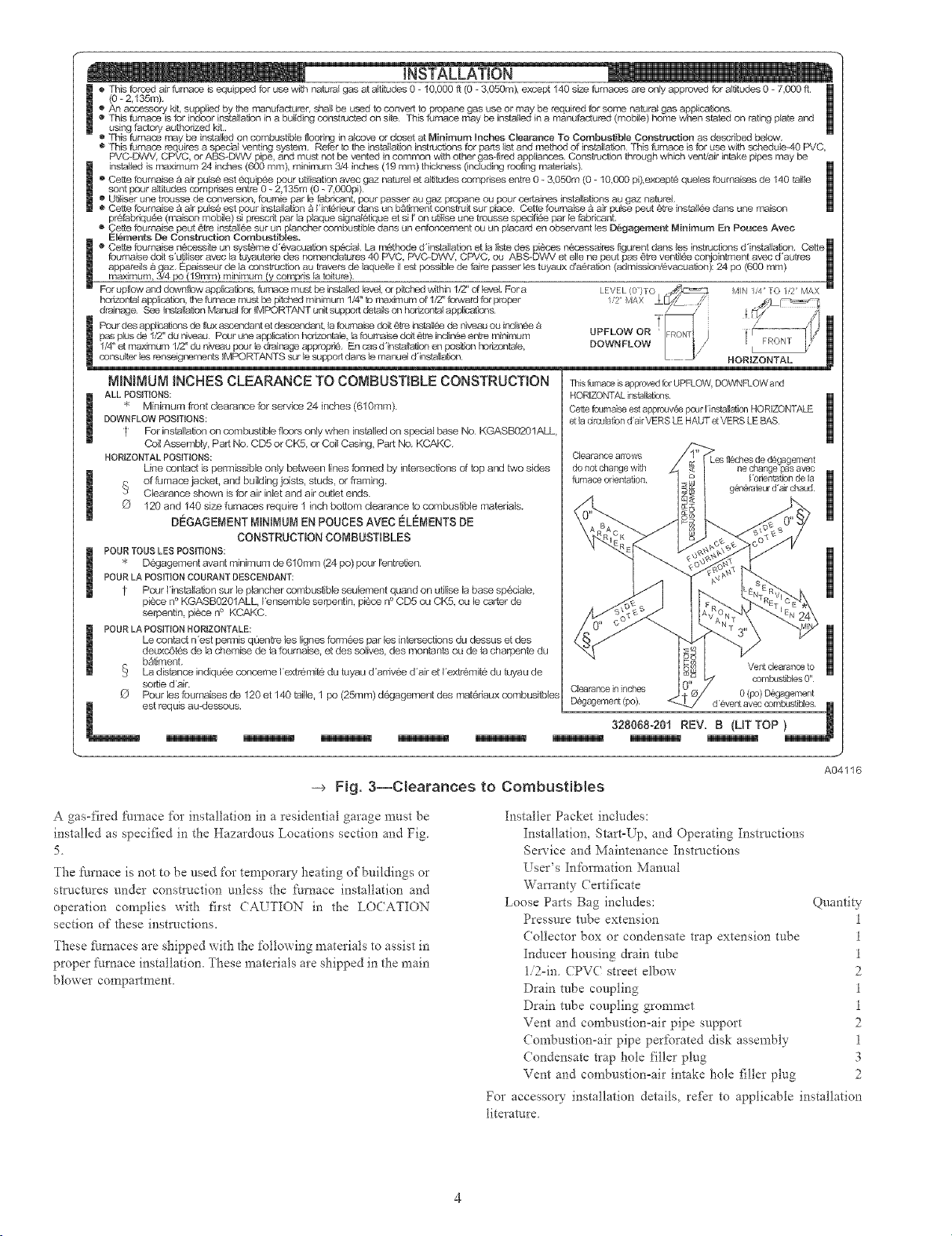
See Fig. 3 for required clearances to combustibles.
Maintain a l-in. clearance fiom combustible materials to supply air
ductwork for a distance of 36 inches horizontally from the ftmaace.
See NFPA 90B or local code _br t:urther requirements.
These furnaces SHALL NOT be installed directly on carpeting,
tile, or any other combustible material other than wood flooring. In
downflow installations, factory accesso_' floor base MUST be
used when installed on combustible materials and wood flooring.
Special base is not required when this Nriaace is installed on
manufacturer's (:oil Assembly Part No. CD5 or CK5, or when (Toil
Box Part No. KCAKC is used. These fi/rnaces are suitable for
installation in a structure built on site or a manu£_ctured building
completed at final site. The design of this furnace line is NOT
C.S.A. (formerly AGA and CGA) design-certified for installation
in recreation vehicles, manufactured (mobile) homes or outdoors.
This Nmace is designed for continuous return-air minimum
temperature of 60 °F db or intermittent operation down to 55°F db
such as when used with a night setback thermostat. Return-air
temperature must not exceed 85°F db. Failure to follow fl_ese
remm air limits may affect reliability of heat exchangers, motors
and controls. (See Fig. 4.)
These Nmaces are shipped with the drain and pressure robes
connected for UPFLOW applications. Minor modifications are
required when used in DOWNFLOW, HORIZONTAL RIGHT, or
HORIZONTAL LEFT (supply-air discharge direction) applica-
tions as shown in Fig. 1. See details in Applications section.
This Nrnace must be installed with a direct-vent (combustion air
and flue) system and a fi_ctory accessory termination kit. In a
direct-vent system, all air for combustion is taken directly fiom the
outside atmosphere and all flue products are discharged to tl_e
outside atmosphere. See fi/rnace and factoQ" accessory termination
kit instructions for proper installation.
Never test for gas leaks with an open flame. Use a commercially
available soap solution made specifically for the detection of leaks
to check all connections as specified in the GAS PIPING section
of these instrtlctions.
Always install furnace to operate within the furnace's intended
temperature-rise range with a duct system which has an external
static press-are within the allowable range as specified in the SET
TEMPERATURE RISE section of these insm/ctions.
When a /:umace is installed so that the supply ducts cat_" air
circulated by the _imaace to areas omside the space containing tl_e
Nmace, the return air must also be handled by a duct(s) sealed to
the furnace casing and terminating outside the space containing the
i:t_rnace.
Page 3
O
AIRFLOW
TYP
OUTLET
A m
, 1biN DiA GAS CONN
27
CONDENSATE DRAIN
TRAP LOCATION _
(DOWNFLOW &
HORIZONTAL RIGHT)
OR ALTERNATE
30 i_,,
7m-IN DIA
POWER CONN
I_z-IN DIA
THERMOSTAT ENTRY
)NN
1
18 _,_
i
I SiDE INLET
I
I
I
CONDENSATE
SiDE iNLET
DRAIN LOCATION
(UPFLO\A/}
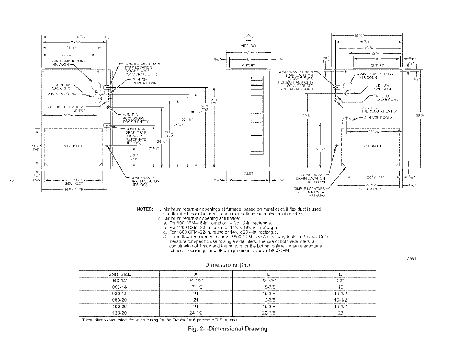
NOTES:
1. Minimum return-air openings at furnace, based on metal duct. If flex duct is used,
see flex duct manufacturer's recommendations for equivalent diameters.
2. Minimum return-air opening at furnace:
a, For 800 CFM-16qn, round or 14V_x 12in, rectangle.
b. For 1200 CFM-20qn. round or 14V,x 19V2qn.rectangle.
c. For 1600 CFM-22-in. round or !4_/_x 23V,-in. rectangle.
d. For airflow requirements above 1800 CFM, see Air Delivery table in Product Data
literature for specific use of single side inlets. The use of both side inlets, a
combination of 1 side and the bottom, or the bottom only will ensure adequate
return air openings for airflow requirements above 1800 CFM.
UNIT SBZE A D E
040-14* 24-1/2" 22-7/8" 23*
060-14 17-1/2 15-7/8 16
080-14 21 19_3/8 19-1/2
080-20 21 19_3/8 19-1/2
100=20 21 19_3/8 19-1/2
120=20 24-1/2 22-7/8 23
* These dimensions reflect the wider casing for the Trophy (96,6 percent AFUE) furnace
Fig. 2--Dimensional Drawing
INLE_ DRA{N LOCATION
Dimensions (in.)
DIMPLE LOCATORS
FOR HORIZON 17_,L
HANGING
A99111
Page 4
iNSTALLATION
This forced air furnace is equipped for use with natural gas at altitudes 0 - 10,000 f_(0 - 3,050m), except 140 size f:dmaces are orlly approved for altitudes 0 - 7,000 ft
(0 - 2,135m).
e An accessory kit, supplied by the manufacturer, sbe}l be used to convert topropane gas use or may be required for some natural gas applications.
o This furnace is for indoor installation in a building constructed on site This furnace may be instaltadin a mant_astored (mobile) home when stated on rating p_ate and
using factory authorized kit.
o This Furnace may be installed on combustibta flooring in a_cove or closet at Minimum Inches Clearance To OombustiMe Construction as described below.
o This furnace requires a spedal venting system Refer to the installation instructions for parts list and method of installation This furnace is for use with scheduta4O PVC,
PVC_DWV, CPVC, or ABS_DV',N pipe, and must not be vented in comrr'_n with other gas_red appliances. Construction through which vent/air intake pipes may be
installed is maximum 24 inches (600 mm), minimum 3/4 inches (19 mm) thickness (including roo_ng materials) m
o Cette foumaise & air pulse est 6quip6e pou_ utilisation avec gaz naturefl et aYdtudes comprises entre 0 _ 3,050m (0 - 10,000 pi),except6 quetas foumaises de 140 tai_ta
sont pour aNtudas comprises entre 0 _ 2,135m (0 - 7,000pi)
o Uti_iser une trousse de conversion, foumta par le fabdcant, pour passer au gaz propane ou pour certaines tastNiations au gaz natureL
o Cette foumNse & air puls6 est pour installatbn B I'tat@ieur dans un b_timent construit sur place Cette foornaise a air pu}se peut 6tre insta_lee dans une maison
p@_bbdquSe (maison mobile) si prescdt par la plaque signatatique et si I' on uti_ise une trousse spedfi_e par le fabbeant.
o Cette foumaise peut @tre instaJl6e sur un ptancher combustibta dans un enfoncemerlt ou un ptacard en obseNant tas D_gagement Minimum En Pouces Avec
Elenlents De Construction Oombustibtas.
I o Cette foumaise n@cesqte un systg_ne d'evacuation special La m_thode d'instaltation et la liste des pi_ces necessaires figurent dans tas instructions d'instailation Cet[e_
fournaise doit s'@liser avec la tuyautede des nom_nctatures 40 PVC, PVC-DVeV, CPVC, ou ABS-D'¢,N et elta ne peut pas _tre ventil@e conjointment avec d'autres
appareils & gaz. Epaisseur de _a constiuction au travers de laquelta il est possible de faire passer tas tuyaux d'a_ration (admisstan/_vacuation): 24 pc (600 mm) []
maximum, 3/4 pc (19ram) minimum (y compris la toitu_)
For up[low and downflow applicatbns, forr_qce must be installod level, a- pitched within 1/Z' of level, For a LEVEL (0 /TO ,_,,,]Z:::_::£3 \4IN 1_4 TO 1_2 MAX
horizontal app}icatbn, the furnace must be pitched minimum 1/4" to maximorn of 1/Z _faward for proper 1,2 MA£ _.._/ .Ca" . _¢_h_- l
@_inage See Ir_staltaflon Mar_al fa- IMPORTANT unit support deta_s Gnhorisontaf apdicattans --/ " I_ _
_ Pourdeeapp!k;_ionsde,uxascer,dantetde_scendant la roornaise doit @_einstafl_ de niveauouindi._e_ !_FRONTI _ / ----_('(1 _
as UPFLOW OR [_
p plusde I/Z'dunive_ Pooruneapplicatbr_hodzontale lafournaisedoit_treinclta&ee,Y.rerninimum ) FRON]| /
1/4"etmaximcrml/Z'duniveaupour_edrairk_geapprc_.. En c_sd'instaltation erngositic_q berisontaJe, DOWNFLOW _ /. _ -K,_ L/
_a e_sta_ion L _" HORIZONTA_ [_
NN_U_ INCHES CLEARANCE TO CONBUSTtBLE CONSTRUCTION
ALL POSITIONS:
* Minimum front clearance for service 24 inches (61gram).
DOWNFLOW POSITIONS:
For installation on combustible floors only when installed on spedal base No KGASBO201ALL
Coi_Assembly Pad No. CD5 or CKS. or Coil Casing, Part No. KCAKC.
HORIZONTAL POSITIONS:
Line contact is permissible only between lines formed by intersections of top and two sides
of furnace jacket, and building joists, studs, or framing.
Clearance shown is for air in_et and air outlet ends.
120 and 140 size furnaces require 1 inch bottom clearance to combustible materials.
DEGAGEMENTNNMUN ENPOUCESAVEC ELEMENTSDE
POUR TOUS LES POSITIONS:
* Dg%Jagement avant minimum de 61 gram (24 pc) pour rentretien
POUR LA POSITION COURANT DESCENDANT:
Pour Hnstallation sur le p_ancbar combustible seulement quand on utilise la base spedale,
piece n o KGASBC/201ALL Fensemble se@entin, piece noCD5 ou CKS. ou le carter de
se@entin, piece no KCAKC.
POUR LA POSITION HORIZONTALE:
Le contact n'est permis qOenb_ les lignes fortunes bar Jes intersections du dessus et des
deuxc6t@s de la chemise de la fournaise, et des so_ives, des montanta ou de la charpente du
b_timent.
La distance indiqu6e concerne I'extr_mit@ du tuyau d'ardv@e d'ak et I'extrcmit@ du tuyau de
sortie d'air.
Pour les fournaises de 120 et 140 taille. 1 pc (25ram) dg_gagement des mat&iaux combusitbles
est requis au-dessous
CONSTRUCTIONCONBUSTIBLES
This Drnace is approved for UPFLOW, DOWNFLOW and
HORIZONTAL installations.
Cet[e toumaise esl approuvee pour Hnstallation HORIZONTALE
st la drculatisn d'air VERS LE HAUT etVERS LE BAS
C[esrance arrows
do not change with
furnace orientation
Cbarance in inches
Degagemest (pc),
ne change tJas avec
I'otientatisn de is
gen@atecr d'air chaud
VelY{cle&.8rice to
combustibles 0"
0 (pc) D_gagement
1
[]
--> Fig. 3--Clearances to Combustibles
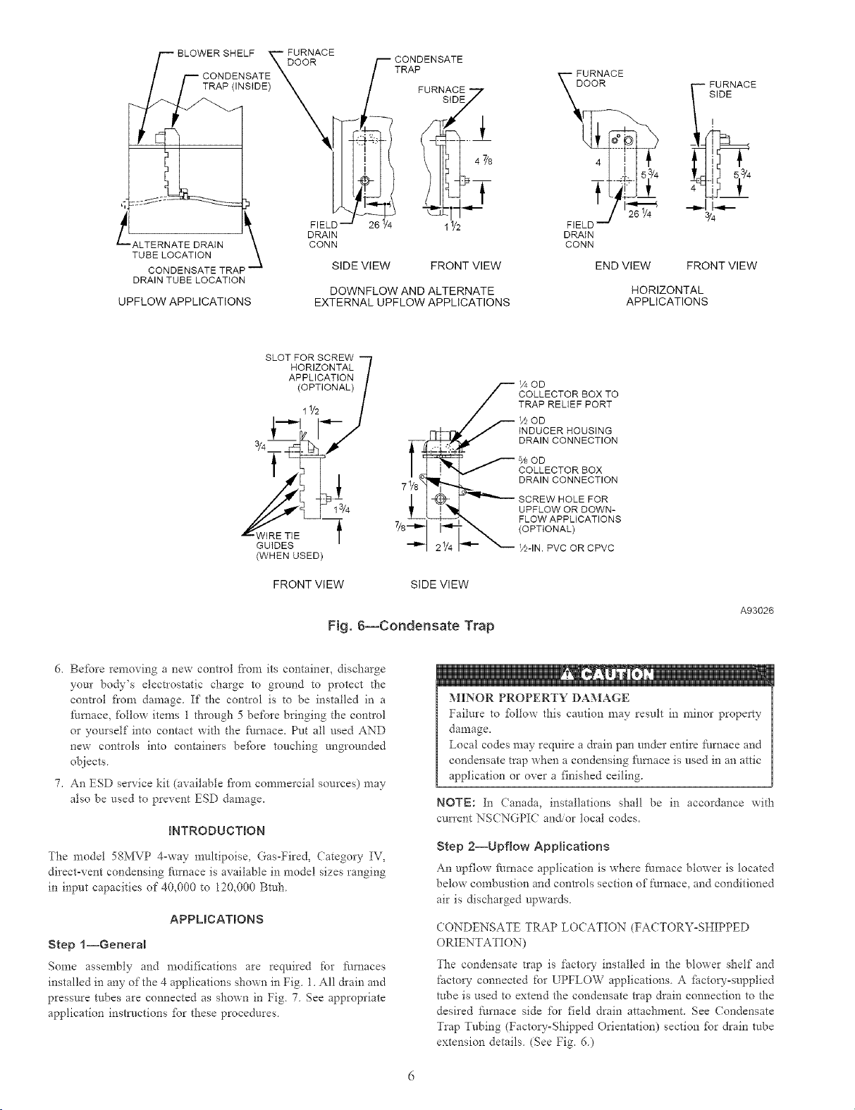
A gas-fired fttrnace %r installation in a residential garage must be
installed as specified in the Hazardous Locations section and Fig.
5.
The L'umace is not to be used for temporary heating of buildings or
stn_ctures under construction unless the furnace installation and
operation complies with first CAUTION in the LO(ATION
section of these instructions.
These [imaaces are shipped with the following materials to assist in
proper Nmace installation. These materials are shipped in the main
blower compartment.
A04116
Installer Packet includes:
Installation, Start-Up, and Operating Instn_ctions
Service and Maintenance Inst_qactions
User's Information Manual
Wan'anty Certificate
Loose Parts Bag includes: Quantity
Pressure mbe extension 1
Collector box or condensate trap extension tube 1
Inducer housing drain tube 1
li2oia. CPVC street elbow 2
Drain tube coupling 1
Drain robe coupling grommet 1
Vent and combustionoair pipe support 2
Combustion-air pipe perforated disk assembly 1
Condensate trap hole filler plug 3
Vent and con£bustionoair intake hole filler plug 2
For accessory installation details, re_r to applicable installation
titeratt_re
Page 5
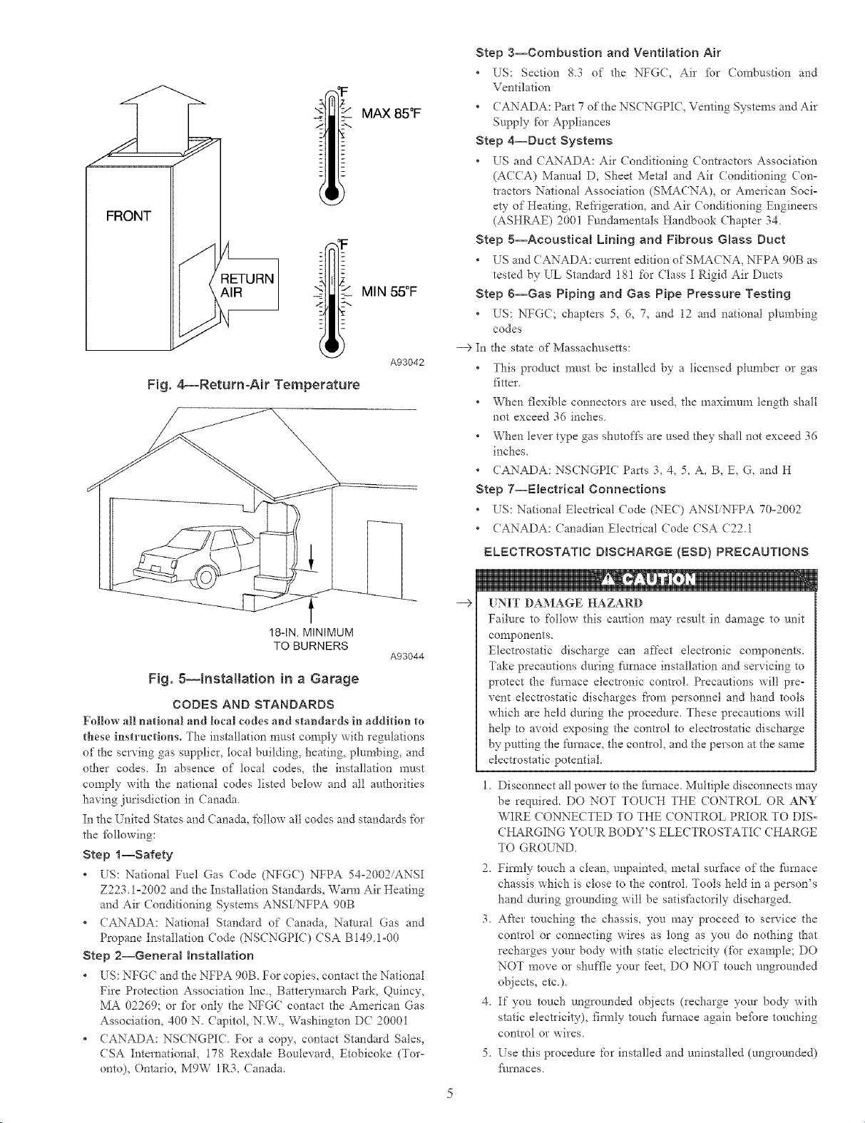
_ MAX 85°F
Fig, 4_Retum-Air Temperature
F
'F
2 MIN 55°F
A93042
Step 3--Combustion and Ventilation Air
* US: Section 83 of the NFGC, Air fbr Combustion and
Ventilation
CANADA: Part 7 of the NSCNGPIC, Venting Systems and Air
Supply for Appliances
Step 4--Duct Systems
* US and (ANADA: Air (onditioning (ontractors Association
(ACCA) Manual D, Sheet Metal and Air Conditioning Con-
tlactors National Association (SMACNA), or American Soci-
ew of Heating, Refrigeration, and Air Conditioning Engineers
(ASHRAE) 2001 Fundamentals Handbook Chapter 34
Step 5--Acoustical Lining and Fibrous Gmass Duct
* US and (ANADA: current edition of SMA(NA, NFPA 90B as
tested by UL Standard 18! for (lass I Rigid Air Ducts
Step 6--Gas Piping and Gas Pipe Pressure Testing
* US: NFG(; chapters 5, 6, 7, and 12 and national plumbing
codes
--> In
the state of Massachusetts:
This product must be installed by a licensed plumber or gas
fitter.
When flexible connectors are used, the n_axinmm length shall
not exceed 36 inches
When lever type gas shutoffls are used they shall not exceed 36
inches.
CANADA: NSCNGPIC Parts 3, 4, 5, A, B, E, G, and H
Step 7--Emectrical Connections
* US: National Electrical (:ode (NEC) ANSI NFPA 70°2002
CANADA: Canadian ElectIical (:ode CSA (722.1
ELECTROSTATIC DBSCNARGE {ESD) PRECAUTIONS
18-1N. MINIMUM
TO BURNERS
A93044
Fig. 8--_nstallatJon in a Garage
CODES AND STANDARDS
FMlow MI national and locM codes and standards in addition to
these instructions° The installation must comply with regulations
of the serving gas supplier, local building, heating, plumbing, and
other codes. In absence of local codes, the installation must
comply with the national codes listed below and all authorities
having jurisdiction in Canada.
In the United States and Canada, follow all codes and standards for
the fbllowing:
Step l--Safety
* US: National Fnet Gas (:ode (NFGC) NFPA 54-2002/ANSI
Z223.1o2002 and the Installation Standards, Warm Air Heating
and Air Conditioning Systems ANSI NFPA 90B
* CANADA: National Standard of Canada, Natural Gas and
Propane Installation Code (NSCNGPIC) (SA BI49H-00
Step 2--General hstaHation
* US: NFG( and the NFPA 90B. For copies, contact the National
Fire Protection Association Inc., Batte_rnarch Park, Quincy,
MA 02269; or for only the NFG( contact the American Gas
Association, 400 N. Capitol, N.W., Washington DC 20001
* CANADA: NSCNGPI(. For a copy, contact Standard Sales,
CSA International, 178 Rexdale Boulevard, Etobicoke (Tof
onto), Ontario, M9W 1R3, (anada.
e
-->
[NIT DAMAGE HAZARD
Failure to follow this caution may result in damage to unit
components.
Electrostatic discharge can affect electronic components.
Take precautions during furnace installation and servicing to
protect the furnace electronic control. Precautions will pre-
vent electrostatic discharges t]'om personnel and hand tools
which are held during the procedure. These precautions will
help to avoid exposing the control to electlostatic discharge
by putting the t:umacQ the control, and the person at the same
electrostatic potential.
1. Disconnect all power to the furnace. Multiple disconnects may
be required. DO NOT TOU(H THE CONTROL OR ANY
WIRE CONNE(TED TO THE ( ONTROL PRIOR TO DIS-
CHARGING YOUR BODY'S ELECTROSTATI( CHARGE
TO GROUND,
2 Firefly touch a clean, unpainted, metal surface of the furnace
chassis which is close to the control. Tools held in a person's
hand during grounding will be satisfactorily discharged.
3. After touching the chassis, you may proceed to service the
control or connecting wires as tong as you do nothing that
recharges your body with static electricity (fbr example; DO
NOT move or shuffle your feet, DO NOT touch ungrounded
objects, etc)
4 If you touch ungrounded objects (recharge your body with
static electricity), firmly touch f_/rnace again befbre touching
control or wires
5 Use this procedure for installed and uninstalled (ungrounded)
f_/rnaces
Page 6
__D FURNACE
TRAP (INSIDE_ X[
OOR
/_ CONDENSATE
/ TRA uRNAOE7
] S'DV
/o
£_2% ......
_1 FURNACE
OOR
-- FURNACE
SIDE
FIELD--
DRAIN
CONN
TUTo OOSO ETRAP
DRAIN TUBE LOCATION
UPFLOW APPLICATIONS
SIDE VIEW FRONT VIEW
DOWNFLOW AND ALTERNATE
EXTERNAL UPFLOW APPLICATIONS
s'-°7'-%:°:U7
(OPTIONAL) /
W, ET,E
GUIDES
(WHEN USED)
FRONT VIEW SIDE VIEW
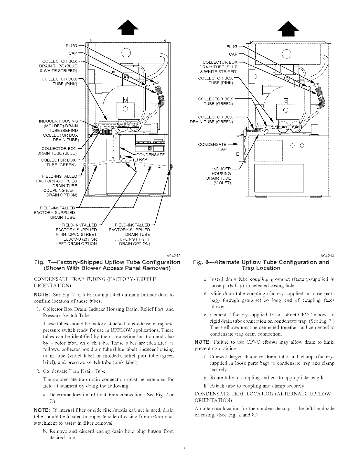
Fig. 6--Condensate Trap
26_/4 1_/2
71/8
l
FIELD --
DRAIN
CONN
END VIEW FRONT VIEW
COD
COLLECTOR BOX TO
TRAP RELIEF PORT
_OD
INDUCER HOUSING
DRAIN CONNECTION
'_OD
COLLECTOR BOX
DRAIN CONNECTION
SCREW HOLE FOR
UPFLOW OR DOWN-
FLOW APPLICATIONS
(OPTIONAL)
YnlN. PVC OR CPVC
¾
HORIZONTAL
APPLICATIONS
A93026
6, Be%re removing a new contlol t'rom its container, discharge
your body's electrostatic charge to ground to protect the
control t'rom damage. If the control is to be installed in a
furnace, follow items 1 through 5 before bringing the control
or yourself into contact with the fhrnace. Put all used AND
new controls into containers be_bre touching ungrounded
objects.
7. An ESD service kit (available fi'om commercial sources) may
also be used to prevent ESD damage.
INTRODUCTION
The model 58MVP 4-way muhipoisQ Gas-Fired, (ategory IV,
direct-vent condensing fknace is available in model sizes ranging
in input capacities of 4@000 to 120,000 Btuh
APPUCATIONS
Step l--General
Some assembly and modifications are required for furnaces
installed in any of the 4 applications shown in Fig. 1. All &ain and
pressure robes are connected as shown in Fig 7 See appropriate
application instrnctions _br these procedures
: O 'I
MINOR PROPERTY DAMAGE
Failure to fbllow this caution may result in minor property
damage.
Local codes may require a drain pan under entire furnace and
condensate trap when a condensing fhmace is used in an attic
application or over a finished ceiling.
NOTE: In (anada, installations shall be in accordance with
cun'ent NS(NGPIC andor local codes.
Step 2--Upflow Applications
An upflow furnace application is where furnace blower is located
below combustion and controls section of furnace, and conditioned
air is discharged upwards
CONDENSATE TRAP LOCATION (FACTORY-SHIPPED
ORIENTATK)N)
The condensate trap is factory installed in the blowm shelf and
factory connected for UPFLOW applications. A fi_ctow-supplied
robe is used to extend the condensate trap drain connection to the
desired furnace side for field drain attachment. See Condensate
Trap Tubing (Factow-Shipped Orientation) section for drain robe
extension details. (See Fig. 6.)
Page 7
COLLECTOR
DRAIN TUBE (BLUE
& WHITE STRIPED)
COLLECTOR
TUBE (PINK)
(MOLDED) DRAIN
TUBE (BEHIND
COLLECTOR BOX
DRAIN TUBE)
DRAIN TUBE (BLUE)
COLLECTOR BOX
TUBE (GREEN)
FACTORY-SUPPLIED
DRAIN TUBE
COUPLING (LEFT
DRAIN OPTION)
FIELD-INSTALLED
FACTORY-SUPPLIED
DRAIN TUBE
FACTORY-SUPPLIED
//2 -IN CPVC STREET
LEFT DRAIN OPTION
PLUG
CAP
FIELD-INSTALLED
ELBOWS (2) FOR
FIELD-INSTALLEE
FACTORY-SUPPLIED
DRAIN TUBE
COUPLING (RIGHT
DRAIN OPTION)
DRAIN TUBE (BLUE
& WHITE STRIPED)
COLLECTOR BOX
TUBE (PINK)
COLLECTOR BOX
TUBE (GREEN)
COLLECTOR BOX
DRAIN TUBE (GREEN)
TRAP
HOUSING
DRAIN TUBE
(VIOLET)
©
O O
A94213
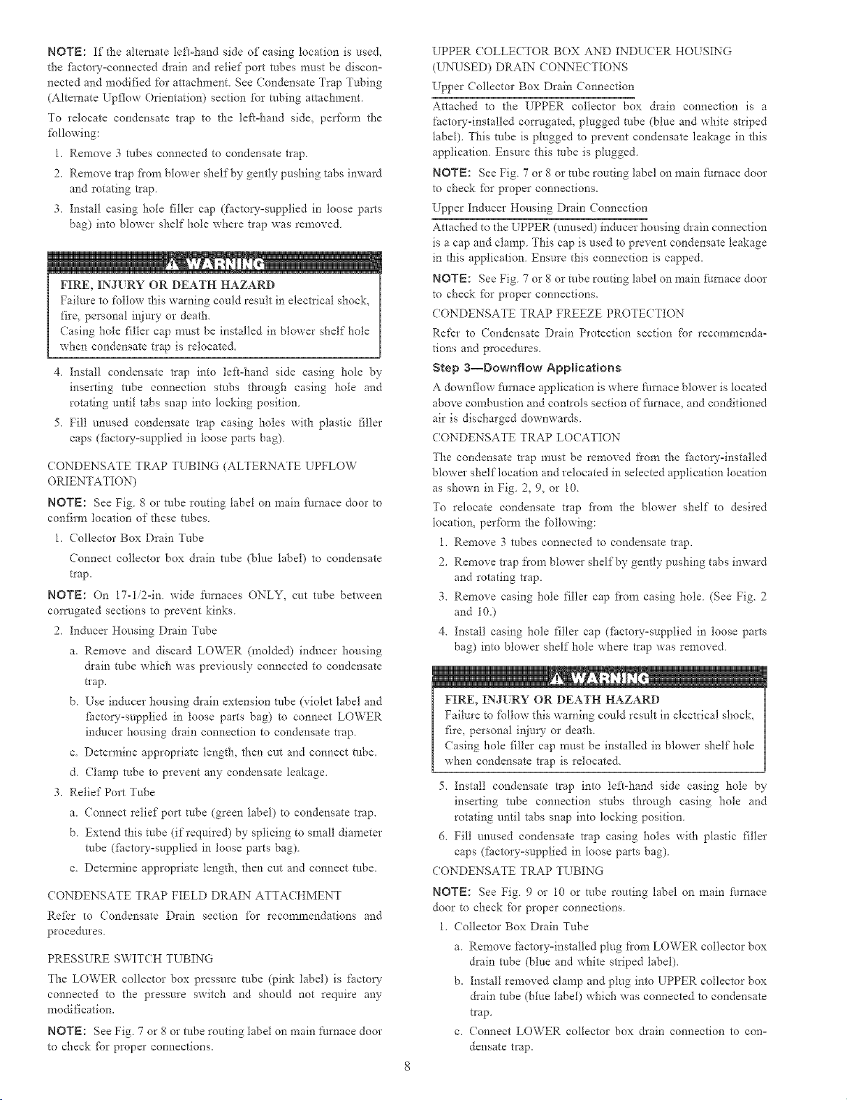
Fig. 7--Factory-SNpped Upflow Tube Configuration
(Shown With Blower Access Panel Removed}
(ONDENSATE TRAP TLTBING (FACTORY_SHIPPED
ORIENTATION)
NOTE: See Fig 7 or tube routing label on main furnace door to
confirm location of these tubes
1. Collector Box Drain, Inducer Honsing Drain_ Relief Port, and
Pressure Switch Tubes
These tubes should be factory attached to condensate trap and
pressure switch ready for use in UPFLOW applications. These
robes can be identified by their connection location and also
by a color label on each tube. These tubes are identified as
follows: collector box &ain tube (blue label), inducer housing
&ain robe (violet label or molded), relief port robe (green
label), and pressure switch robe (pink label).
2. Condensate Trap Drain Tube
The condensate trap drain connection must be extended for
field attachment by doing the fbllowing:
a. Detem_ine location of field drain connection. (See Fig. 2 or
7.)
NOTE: If internal filter or side filter media cabinet is used., &ain
robe should be located to opposite side of casing flora return duct
attachment to assist in filter removal
b. Remove and discard casing drain hole plug button from
desired side.
A94214
Fig. 8--Alternate Upflow Tube Configuration and
Trap Location
c Install drain tube coupling grommet (fScto_--supplied in
loose parts bag) in selected casing hole.
d. Slide &ain robe coupling (fi_ctoryosupplied in loose parts
bag) through grommet so long end of coupling fitces
blower.
e Cement 2 factolw-supplied 1/2-in. street (PVC elbows to
rigid drain tube connection on condensate trap. (See Fig. 7.)
These elbows must be cemented together and cemented to
condensate trap drain connection.
NOTE: Failure to use CPVC elbows may allow drain to kink,
preventing draining.
f\ (onnect larger diameter drain robe and clamp (factor-
supplied in loose parts bag) to condensate trap and clamp
securely.
g. Route robe to coupling and cut to appropriate length.
h. Attach robe to coupling and clamp securely.
COND]_NSATE TRAP LOCATION (ALTERNATE UPFLOW
ORIENTATION)
An alternate location for the condensate trap is the leR_hand side
of casing. (See Fig. 2 and 8.)
Page 8
NOTE:Ifthealternateleft-handsideofcasinglocationisuse&
thefhctory-connecteddrainaridreliefportrobesmustbediscon-
nectedandmodifiedtbrattachmenLSeeCondensateTrapTubing
(AlternateUpflowOrientation)sectiont\_rrobingattachment
Torelocatecondensatetlaptotheleft-handside,performthe
fbllowing:
1.Remove3tubesconnectedtocondensatetrap
2.Removetlapfiomblowershelfbygentlypushingtabsinward
androtatingtrap
3.Installcasingholetillercap(factory-suppliedinlooseparts
bag)intoblowershelfholewheretrapwasremoved.
FIRE,IN!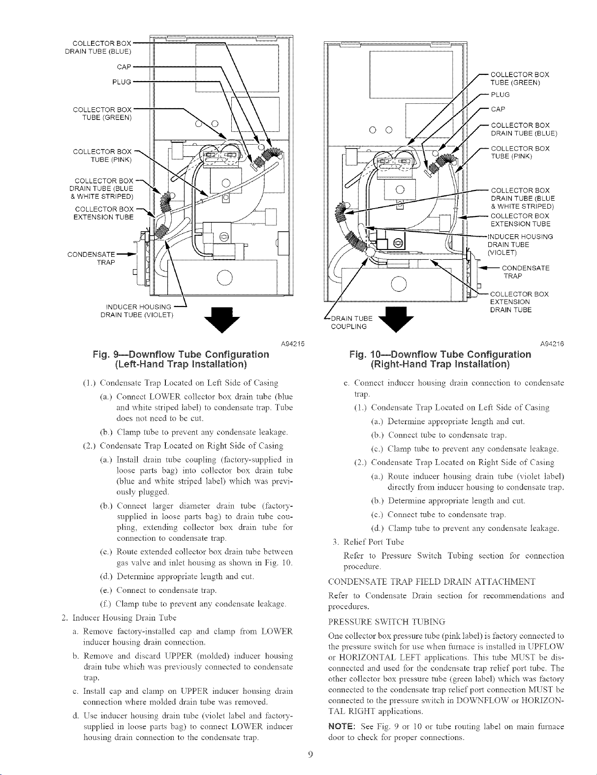
COLLECTOR BOX
DRAIN TUBE (BLUE)
CAF
PLUG
COLLECTOR BOX
TUBE (GREEN)
COLLECTOR BOX
TUBE (PINK)
O O
TUBE (GREEN)
BOX
DRAIN TUBE (BLUE)
BOX
TUBE (PINK)
DRAIN TUBE (BLUE
& WHITE STRIPED)
COLLECTOR BOX
EXTENSION TUBE
TRAP
©
iNDUCER HOUSING
DRAIN TUBE (VIOLET)
Fig. 9--Downflow Tube Configuration
(Left-Hand Trap Installation)
(1) Condensate Trap Located on Left Side of Casing
Ca) Connect LOWER collector box &ain robe (blue
and white striped label) to condensate trap. Tube
does not need to be cut.
(b) Clamp tube to prevent any condensate leakage.
(2) Condensate Trap Located on Right Side of Casing
Ca) Install drain tube coupling (fi_cto_--supplied in
loose parts bag) into collector box drain robe
(blue and white striped label) which was previ-
ously plugged.
(b) Connect larger diameter &ain robe (gtctory-
supplied in loose parts bag) to &ain tube cou-
pling, extending collector box drain robe for
connection to condensate trap
(c0 Route extended collector box &ain tube between
gas valve and inlet housing as shown in Fig. 10.
(&) Determine appropriate length and cut.
(e.) Connect to condensate trap.
(f.) Clamp robe to prevent any condensate leakage.
2. Inducer Housing Drain Tube
a. Remove fi_ctoLy-installed cap and clamp from LOWER
inducer housing drain connection.
b. Remove and discard UPPER (molded) inducer housing
&ain robe which was previously connected to condensate
t_ap,
c Install cap and clamp on UPPER induce* housing &ain
connection whe*e molded &ain robe was removed,
d, Lse inducer housing &ain robe (violet 1abel and factory°
supplied in loose parts bag) to connect LOWER inducer
housing &ain connection to the condensate t*ap
A94215
DRAIN TUBE (BLUE
BOX
& WHITE STRIPED)
EXTENSION TUBE
DRAIN TUBE
(VIOLET)
O TRAP
EXTENSION
DRAIN TUBE
DRAIN TUBE
COUPLING
A94216
Fig. 10--Downflow Tube Configuration
(Right-Hand Trap Installation)
e Connect inducer housing drain connection to condensate
trap.
(1.) Condensate Trap Located on Left Side of Casing
Ca.) Determine appropriate tengtia and cut.
(b.) Connect tube to condensate tlap.
(c.) Clamp robe to prevent any condensate leakage.
(20 Condensate Trap Located on Right Side of Casing
Ca.) Route in&cot housing drain robe (violet label)
directly from inducer housing to condensate tlap.
(b.) Determine appropriate lengd_ and cut.
(c.) Connect robe to condensate trap.
(&) Clamp robe to prevent any condensate leakage.
3. Relief Port Tube
Refkr to Pressure Switch Tubing section for connection
procedure.
CONDENSATE TRAP FIELD DRAIN ATTACHMENT
Refkr to Condensate Drain section fbr recommendations and
procedures.
PRESSURE SWITCH TUBING
One collector box pressure tube (pink label) is factory connected to
the pressure switch fbr use when furnace is installed in UPFLOW
or HORIZONTAL LEFT applications. This robe MUST be dis-
connected and used *;or the condensate trap relief port robe. The
other collector box pressure robe (green label) which was *:actory
connected to the condensate trap relief port connection MUST be
connected to the pressure switch in DOVv_FLOW or HORIZON-
TAL RIGHT applications.
NOTE: See Fig. 9 or 10 or robe routing label on main furnace
door to check fbr proper connections.
Page 10
Relocate robes as described below,
1. Disconnect collector box pressure tube (pink label) attached to
pressure switch.
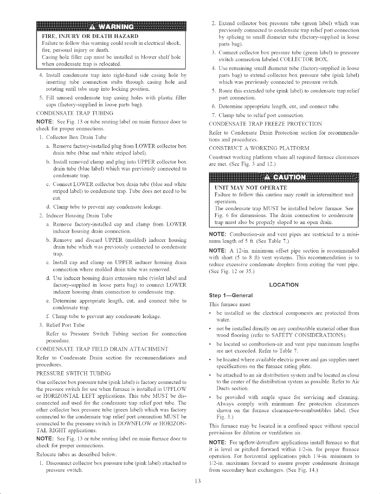
2. Extend collector box pressure tube (green label) which was
previously connected to condensate trap relief port connection
by splicing to small diameter robe (factoD'-supplied in loose
parts bag).
3. Connect collector box pressure tube (green label) to pressure
switch connection labeled COLLECTOR BOX.
4. Extend collector box pressure tube (pink label) which was
previously connected to pressure switch by splicing to remain°
ing small diameter robe (factoD'-supplied in loose parts bag)
5. Route this extended robe (pink label) to condensate t_ap relief
port connection.
6. Determine appropriate length, cut, and connect robe.
7. (lamp robe to relief port connection.
( ONDENSATE TRAP FREEZE PROTE( TION
Refkr to Condensate Drain Protection section %r recommenda-
tions and procedures.
Step 4--Horizontal Left (Supp[yoAir Discharge)
Applications
A horizontal left furnace application is where t_urnace blower is
located to the right of combustion and controls section of furnace,
and conditioned air is discharged to the left.
2 0 _
--€
MINOR PROPERTY DAMAGE
Failure to fbllow this caution may result in minor property
damage.
Local codes may require a drain pan under entire furnace and
condensate trap when a condensing f_lrnace is used in an attic
application or over a finished ceiling.
NOTE: In Canada, installations shall be in accordance with
cmxent NS(NGPIC and/or local codes.
CONDENSATE TRAP LOCATION
The condensate trap must be removed from the fhctow-installed
blowe* shelf'location and relocated in selected application location
as shown in Fig 2or 11.
To relocate condensate trap fi'om the blowe* shelf to desired
location, perfbrm the following:
1. Remove 3 tribes connected to condensate trap.
2. Remove trap from blowe* shelf by gently pushing tabs inward
and rotating trap.
3. Remove casing hole filler cap fiom casing hole (See Fig. 2 or
11)
4. Install casing hole filler cap (fi_ctou-supplied in toose parts
bag) into blower shelf hole where trap was removed
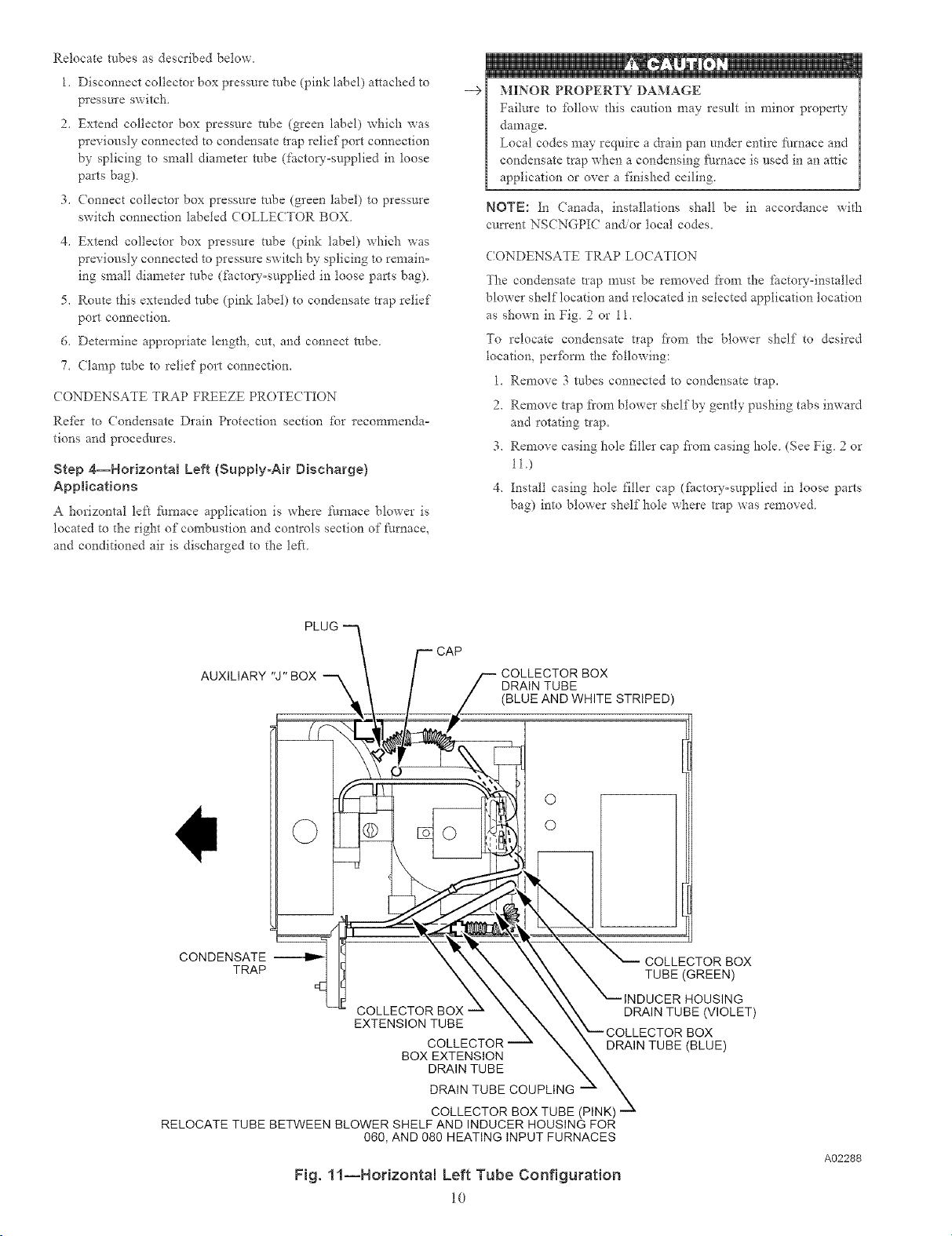
PLUG "-_
t F CAP
AUXILIARY "J" BOX _ \ / f-- COLLECTOR BOX
\ \ / / DRAIN TUBE
/ / (BLUE AND WHITE STRIPED)
CONOE S T 711 "\----\\ --CO ' CTO OOX
TRAP \\\ XX \ TUBE(GREEN)
LL_ \ \ \ \\ "--INDUCER HOUSING
COLLECTOR BOX _ N N \\ DRAIN TUBE (VIOLET)
EXTENSION TUBE X X X_COLLECTOR BOX
.... C_%_L_E.C_T.gR_ N \ DRAIN TUBE (BLUE)
BOX EXTENSION N \
DRAIN TUBE X X
DRAIN TUBE COUPLING _
RELOCATE TUBE BETWEEN BLOWER SHELF AND INDUCER HOUSING FOR
060, AND 080 HEATING INPUT FURNACES
COLLECTOR BOX TUBE (PINK) --_
Fig. 11--Horizontal Left Tube Configuration
10
\
A02288
Page 11
_: iiiiiii!
FIRE, INJURY OR DEATH HAZARD
Failure to fbltow this warning could result in electrical shock
fire, personal injury or death.
Casing hole filler cap must be installed in blower shelf hole
when condensate trap is relocated.
5. Install condensate trap into left-hand side casing hole by
inserting tube connection stubs through casing hole and
rotating until tabs snap into locking position.
6. Fill unused condensate trap casing holes with plastic filler
caps (ilactory=supptied in loose parts bag)
(ONDENSATE TRAP TUBING
NOTE: See Fig. 11 or robe routing label on main fl/rnace door to
check for proper connections
1. (ollector Box Drain Tube
a. Install &ain tube coupling (fhctory=supplied in loose parts
bag) into collector box drain robe (blue label) which was
previously connected to condensate trap.
b. Connect large diameter drain robe and clamp (factory°
supplied in loose parts bag) to drain robe coupling, extend°
ing collector box &ain tube.
c. Route extended robe (blue label) to condensate trap and cut
to appropriate lengd_.
d. Clamp robe to prevent any condensate leakage.
2. Inducer Housing Drain Tube
a. Remove and discard LOWER (molded) inducer housing
drain tube which was previously connected to condensate
trap.
b. Use inducer housing &ain extension tube (violet label and
fhctow-supplied in loose parts bag) to connect LOWER
inducer housing drain connection to condensate trap.
c. Determine appropriate length, cut, and connect robe.
d. Clamp robe to prevent any condensate leakage.
3. Relief Port Tube
a. Extend collector box robe (green label) which was previ=
ously connected to condensate trap by splicing to small
diameter robe (fhctory=supptied in loose parts bag).
b. Rome extended collector box pressure robe to relief port
connection on condensate trap
c. Determine appropriate tength, cuL and connect robe.
d. (lamp robe to prevent any condensate leakage.
(ONDENSATE TRAP FIELD DRAIN ATTA(HMENT
Refkr to Condensate Drain section ibr recommendations and
procedures
PRESS[ RE SWIT(H TUBING
The LOWER collector box pressure tube (pink label) is factow
connected to the High Pressure Switch fbr use when fhrnace is
installed in UPFLOW applications This robe MUST be discon=
nected, extended, rerouted, and then reconnected to the pressure
switch in HORIZONTAL LEFT applications ibr 060 and 080
heating input fl/rnaces.
NOTE: See Fig. 11 or robe routing label on main Nrnace door to
check for proper connections.
ModK}" robe as described below.
1. Disconnect collector box pressure tube (pink label) attached to
High Pressure Switch.
2 Use smaller diameter tube (factou-supplied in loose parts
bag) to extend tube disconnected in item 1.
3 Route extended robe:
a Behind indtlcer housing.
b Between blower shelf and inducer housing.
4 Determine appropriate length, cut, and reconnect tube to High
Pressure Switch connection labeled (OLLE(TOR BOX.
CONDENSATE TRAP FREEZE PROTECTION
Refer to (ondensate Drain Protection section %r recommenda-
tions and procedures
CONSTRU(T A WORKING PLATFORM
Construct working platfbnn where all required furnace clearances
are met (See Fig. 3 and 12)
INIT MAY NOT OPERATE
Failure to %llow this caution may result in intermittent unit
operation
The condensate trap MUST be installed below thrnace. See
Fig. 6 ibr dimensions. The drain connection to condensate
trap must also be properly sloped to an open drain.
NOTE: (onft_ustion=air and vent pipes are restricted to a mini-
mum length of 5 fi. (See Table 7.)
NOTE: A 12°in. minimum offset pipe section is recommended
with short (5 to 8 ft) vent systems. This recommendation is to
reduce excessive condensate droplets fi'om exiting the vent pipe.
(See Fig. 12 or 35.)
Step 5--Horizontal Right {Supply-Air Discharge)
Applications
A horizontal right furnace application is where thrnace blower is
tocated to the 1eft of combustion and controls section of fl/rnace,
and conditioned air is discharged to the right.
1
MINOR PROPERTY DAMAGE
Failure to %11ow this caution may result in minor property
damage
Local codes may require a drain pan under entire furnace and
condensate trap when a condensing fhrnace is used in attic
application or over a finished ceiling.
NOTE: In Canada, installations shall be in accordance with
cmTent NS(NGPIC Installation Codes and/or local codes
NOTE: The auxiliaL'y junction box (J-box) MUST be relocated to
opposite side of furnace casing. (See Fig. 130 See Electrical
Connection section for J°box relocation,
CONDENSATE TRAP LOCATION
The condensate trap must be removed from the ii_ctow=installed
blower shetf location and relocated in selected application location
as shown in Fig 2 or 13.
To relocate condensate trap fi'om the blower shelf to desired
location, peribnn the following:
1 Remove 3 tnbes connected to condensate trap.
2 Remove trap from blowe* shelf by gentty pushing tabs inward
and rotating trap.
3 Install casing hole filler cap (ihctory=supplied in loose parts
bag) into blower shelf hole where trap was removed
11
Page 12
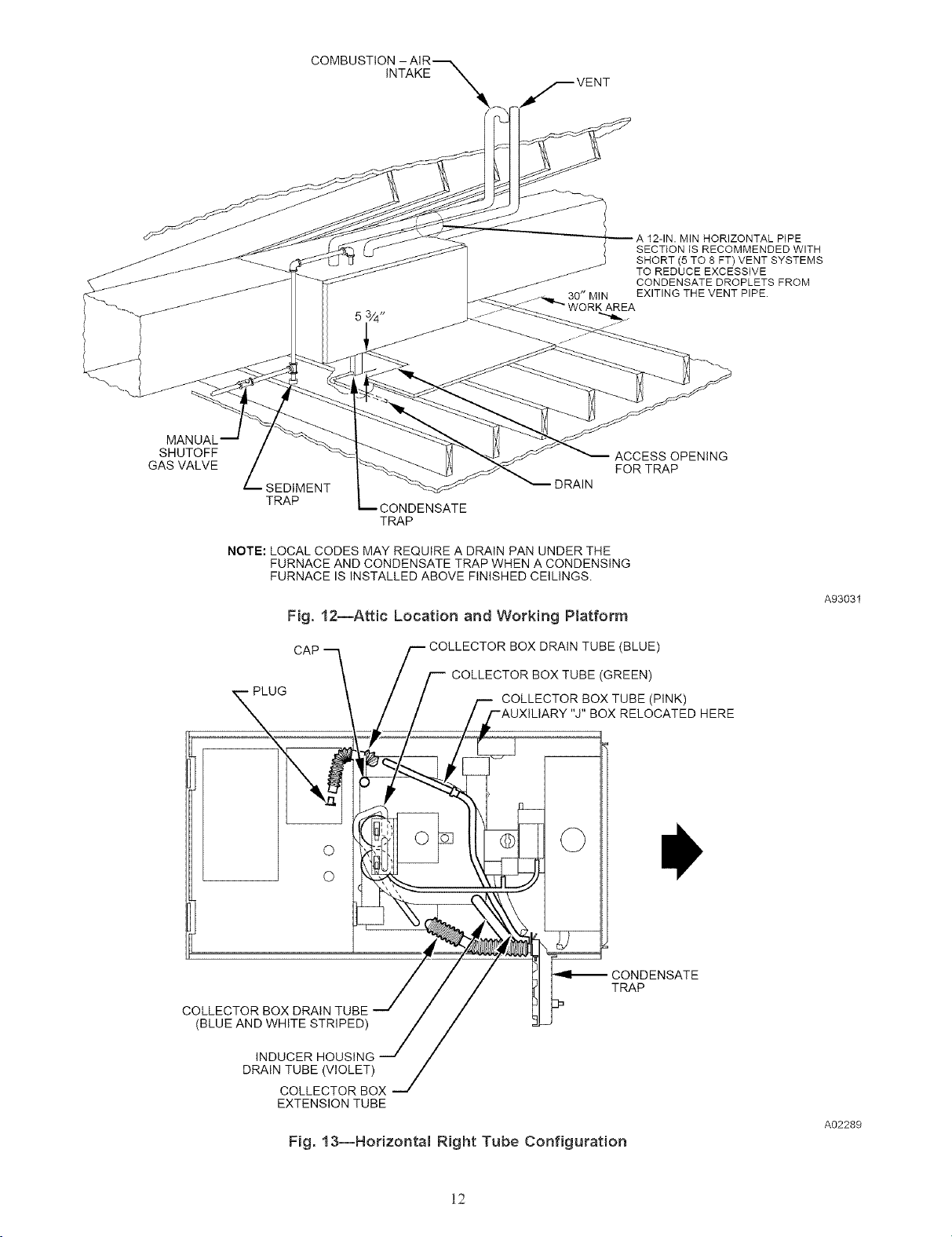
COMBUSTION
INTAKE
VENT
12-1N. MIN HORIZONTAL PIPE
SECTION IS RECOMMENDED WITH
SHORT (5 TO 8 FT) VENT SYSTEMS
TO REDUCE EXCESSIVE
CONDENSATE DROPLETS FROM
EXITING THE VENT PIPE.
SHUTOFF
GAS VALVE
SEDIMENT
TRAP
NOTE: LOCAL CODES MAY REQUIRE A DRAIN PAN UNDER THE
FURNACE AND CONDENSATE TRAP WHEN A CONDENSING
FURNACE IS INSTALLED ABOVE FINISHED CEILINGS.
CONDENSATE
TRAP
DRAIN
Fig. 12--Attic Location and Working Platform
CAP
UG
F COLLECTOR BOX DRAIN TUBE (BLUE)
COLLECTOR BOX TUBE (GREEN)
-- COLLECTOR BOX TUBE (PINK)
BOX RELOCATED HERE
O
O
ACCESS OPENING
FOR TRAP
A93031
COLLECTOR BOX DRAIN TUBE
(BLUE AND WHITE STRIPED)
DRAIN TUBE (VIOLET)
COLLECTOR BOX
EXTENSION TUBE
Fig. 13--Horizontal Right Tube Configuration
CONDENSATE
TRAP
A02289
12
Page 13
_: iiiiiii!
FIRE, INJURY OR DEATH HAZARD
Failure to £4tow this warning could result in electrical shocL
fire, personal injury or death.
Casing hole filler cap must be installed in blower shelf hole
when condensate trap is relocated.
4. Instal! condensate trap into right-hand side casing hole by
inserting tube connection stubs through casing hole and
rotating until tabs snap into locking position.
5. Fill unused condensate trap casing holes with plastic filler
caps (fi_ctoryosupplied in loose parts bag).
CONDENSATE TRAP TUBING
NOTE: See Fig. 13 or tube routing label on main f_./rnace door to
check for proper connections.
1. (ollector Box Drain Tube
a. Remove fitctoryoinstalled plug fiom LOWER collector box
drain robe (blue and white striped label).
b. Install removed clamp and plug into UPPER collector box
&ain tube (blue label) which was previously connected to
condensate t_ap.
c. Connect LOWER collector box drain robe (blue and white
striped label) to condensate trap. Tube does not need to be
cut.
d. (lamp robe to prevent any condensate leakage.
2. Inducer Housing Drain Tube
a. Remove fitctoryoinstalled cap and clamp from LOWER
inducer housing drain connection.
b. Remove and discard UPPER (molded) inducer housing
&ain tobe which was previously connected to condensate
trap.
c. Install cap and clamp on UPPER inducer housing &ain
connection where molded &ain robe was removed.
d. Use inducer housing &ain extension robe (violet label and
factow-supplied in loose parts bag) to connect LOWER
inducer housing &ain connection to condensate trap.
e. Determine appropriate length, cut, and connect robe to
condensate trap.
£ Clamp tube to prevent any condensate leakage.
3. Relief Port Tube
Refer to Pressure Switch Tubing section fbr connection
procedure.
CONDENSATE TRAP FIELD DRAIN ATTACHMENT
Refhr to Condensate Drain section fbr recommendations and
procedures.
PRESSURE SWITCH TUBING
One collector box pressure robe (pink label) is fi_ctory connected to
the pressure switch fbr use when i_urnace is installed in UPFLOW
or HORIZONTAL LEFT applications. This tube MUST be dis°
connected and used for the condensate trap relief port robe. The
other collector box pressure robe (green label) which was fhcto V
connected to the condensate trap relief port connection MUST be
connected to the pressure switch in DOWNFLOW or HORIZON°
TAL RIGHT applications.
NOTE: See Fig. 13 or tube routing label on main Nmace door to
check for proper connections.
Relocate tubes as described below.
1. Disconnect collector box pressure tube (pink label) attached to
pressure switch.
2. Extend collector box pressure robe (green label) which was
previously connected to condensate trap relief port connection
by splicing to small diameter robe (flactou-supptied in loose
parts bag).
3. (onnect collector box pressure robe (green label) to pressure
switch connection labeled COLLECTOR BOX.
4. Use remaining small diameter tube (factory-supplied in loose
parts bag) to extend collector box pressure tube (pink label)
which was previously connected to pressure switch.
5. Route this extended tube (pink label) to condensate trap relief
port connection.
6. Determine appropriate length, cut, and connect robe.
7. Clamp robe to relief port connection.
CONDENSATE TRAP FREEZE PROTECTION
Refer to Condensate Drain Protection section for recommenda-
tions and procedures.
CONSTRUCT A WORKING PLATFORM
Construct working platfbrm where all required furnace clearances
are met. (See Fig. 3 and 12.)
. , IR
[NIT MAY NOT OPERATE
Failure to fbllow this caution may result in intermittent unit
operation.
The condensate trap MUST be installed below l::urnace See
Fig. 6 for dimensions. The drain connection to condensate
trap must also be properly sloped to an open drain.
NOTE: Combustionoair and vent pipes are restricted to a mini-
mun_ length of 5 ft (See Table 7.)
NOTE: A 12oin mininmnl of_;et pipe section is recommended
with short (5 to 8 ft) vent systems. This recommendation is to
reduce excessive condensate droplets fiom exiting the vent pipe.
(See Fig 12 or 35)
LOCATION
Step l--General
This furnace must
* be installed so the electrical components are protected from
water
not be installed directly on any combustible material other than
wood flooring (refer to SAFETY CONSIDERATIONS).
* be located so combustion-air and vent pipe maximum lengths
are not exceeded. Refer to Table 7.
* be located where available electric power and gas supplies meet
specifications on the l::urnace rating plate.
* be attached to an air distribution system and be located as close
to the center of the distribution system as possible. Refer to Air
Ducts section
* be provided with ample space fbr servicing and cleaning.
Always comply with n_inimnm fire protection clearances
shown on the ft_rnace clearanceoto-combustibles label. (See
Fig. 3.)
This Nmace may be located in a confined space without special
provisions £_r dilution or ventilation air.
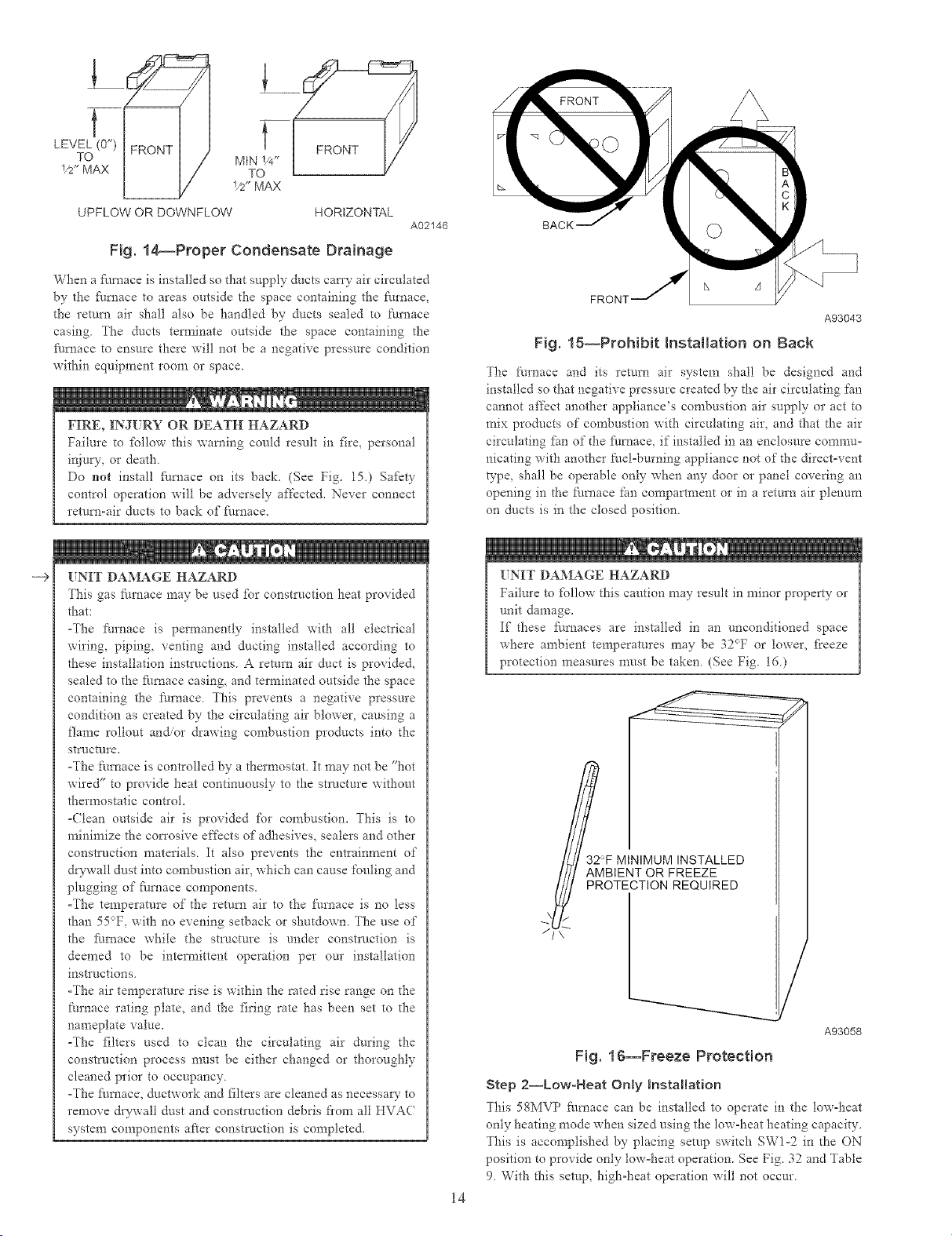
NOTE: For upflowidownflow applications install furnace so that
it is level or pitched fbrward within 1i2oin. for proper fitrnace
operation. For horizontal applications pitch 1i4oin. minimum to
1i2oin. maximunx forward to ensure proper condensate &ainage
from secondary heat exchangers. (See Fig. 14.)
13
Page 14
t
LEVEL (0")
TO
1/2"MAX
V2" MAX
UPFLOW OR DOWNFLOW HORIZONTAL
Fig. 14_Proper Condensate Drainage
When a fhmace is installed so that supply ducts can 7 air circulated
by the _hmace to areas outside the space containing the/hmace,
the return air shall also be handled by ducts sealed to furnace
casing. The ducts terminate outside the space containing the
ihrnace to ensure there will not be a negative pressure condition
within equipment room or space.
FIRE, INJURY OR DEATH HAZARD
Failure to ibllow this warning could result in fire, personal
injury, or death
Do not install fhrnace on its back. (See Fig. 15.) Safbty
control operation will be adversely affecte& Never connect
return-air ducts to hack of filrnace.
A02146
BACK
FRON]
A93043
Fig. 16--Prohibit Installation on Back
The thrnace and its return air system shall be designed and
installed so that negative pressure created by the air circulating fan
cannot affect another appliance's combustion air supply or act to
mix products of confbustion with circulating air, and that the air
circulating fhn of the fhmace, if installed in an enclosure commu-
nicating with another fllel-burning appliance not of the direct-vent
type, shall be operable only when any door or panel covering an
opening in the ihmace fan compartment or in a return air plenum
on dt/cts is in the closed position.
--€ [;NIT DAMAGE HAZARD
This gas fire, ace may be used %r construction heat provided
that:
-The [hrnace is permanently installed with all electrical
wiring, piping, venting and ducting installed according to
these installation instructions A return air duct is provide&
sealed to the ft_raace casing, and terminated outside the space
containing the thrnace This prevents a negative pressure
condition as created by the circulating air blower, causing a
flame rollout an&or drawing combustion products into the
strncttlre.
-The furnace is controlled by a thermostat It may not be "hot
wired" to provide heat continuously to the stlt/cture without
thermostatic control.
-(Dan outside air is provided for combustion. This is to
minimize the con'osive efDcts of adhesives, sealers and other
constn_ction materials. It also prevents the entraimnent of
d_wall dust into combustion air_ which can cause fouling and
plugging of Nrnace components.
-The temperature of the return air to the /hrnace is no less
than 55°F_ with no evening setback or shutdown. The use of
the fimaace while the structure is under construction is
deemed to be intermittent operation per our installation
instructions.
-The air temperature rise is within the rated rise range on the
furnace rating plate, and the firing rate has been set to the
nameplate value.
-The filters used to clean the circulating air during the
construction process nmst be either changed or thoroughly
cleaned prior to occupancy.
-The Nrnace, ductwork and filters are cleaned as necessary to
remove &ywall dust and construction debris fiom all HVA(
system components after construction is completed.
[;NIT DAMAGE HAZARD
Failure to fbllow this caution may result in minor property or
unit damage.
If these farnaces are installed in an unconditioned space
where ambient temperatt_res may be 32_F or lower, freeze
protection measures n-rest be taken (See Fig. 16)
32°F MINIMUM INSTALLED
AMBIENT OR FREEZE
PROTECTION REQUIRED
/
/
A93058
Fig. 16--Freeze Protection
Step 2--LowoHeat Only hstaltation
This 58MVP furnace can be installed to operate in the low-heat
only heating mode when sized using the low-heat heating capacity.
This is accomplished by placing setup switch SWI-2 in the ON
position to provide only low-heat operation. See Fig 32 and Table
9 With this semp_ high-heat operation will not occur
14
Page 15
--€
[SNTT DAMAGE HAZARD
Failure to %llow this caution may result in minor property or
unit damage.
The fhrnace can operate in the high=heat mode when certain
fault conditions occur. The following precautions should be
taken:
l.Size gas piping based on the high-heat input.
2.(hock the high=heat input and adjust it per the main
literature instl-t_ctions.
Step 3--Furnace Location Reiative to Cooling
Equipment
The cooling coil must be installed parallel with or on downstleam
side of furnace to avoid condensation in heat exchanger. When
installed parallel with a _hmace, dampers or other means used to
control flow of air shall be adequate to prevent chilled air t'rom
entering t:tmaace. If dampers are manually operated, they must be
equipped with a means to prevent operation of either unit unless
damper is in Nil=heat or Nil=cool position.
Step 4--Hazardous Locations
m
1¾"
1¾"
1
A89014
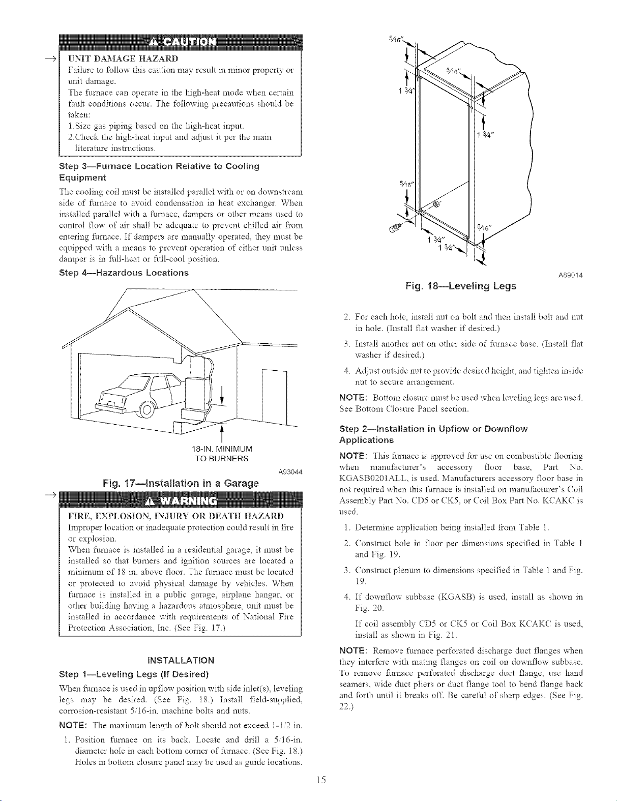
Fig, 18--Leveling Legs
2. For each hole, install nut on bolt and then install bolt and nut
in hole. (Install flat washer if desired.)
3 Install another nut on other side of ftm_ace base (Install flat
washer if desired.)
4 Adjust outside nut to provide desired height, and tighten inside
nut to secure aiTangement
NOTE: Bottom closure must be used when leveling legs are used.
See Bottom (losure Panel section.
18-IN. MINIMUM
TO BURNERS
Fig. 17--installation in a Garage
--€
FIRE, EXPLOSION, INJURY OR DEATH HAZARD
Improper location or inadeq_mte protection could result in fire
or explosion.
When fhrnace is installed in a residential garage, it must be
installed so that burners and ignition sources are located a
minimum of 18 in. above floor The _hmace must be located
or protected to avoid physical damage by vehicles. When
furnace is installed in a public garage, airplane hangar, or
other building having a hazardous atmosphere, unit must be
installed in accordance with requirements of National Fire
Protection Association, Inc. (See Fig. 17.)
INSTALLATION
Step l--Leveling Legs {if Desired)
When I:hmace is used in upflow position with side inlet(s), leveling
legs may be desired. (See Fig. 18.) Install field=supplied,
co_Tosion-resistant 5/16=in. machine bolts and nuts.
NOTE: The maximum length of bolt should not exceed 1=1/2 in.
1. Position Nmace on its back. Locate and drill a 5/16=in.
diameter hole in each bottom corner of Nrnace. (See Fig. 18.)
Holes in bottom closure panel may be used as guide locations.
A93044
Step 2--hstaHation in Upflow or Downflow
Applications
NOTE: _his fhmace is approved for use on combustible flooring
when manul:acmrer's accessory floor base, Part No.
KGASB020 IALL, is used. Manufacturers accessory floor base in
not required when this 5m_ace is installed on manufacturer's (Toil
Assembly Part No. CD5 or CK5, or (oil Box Part No. KCAK( is
used.
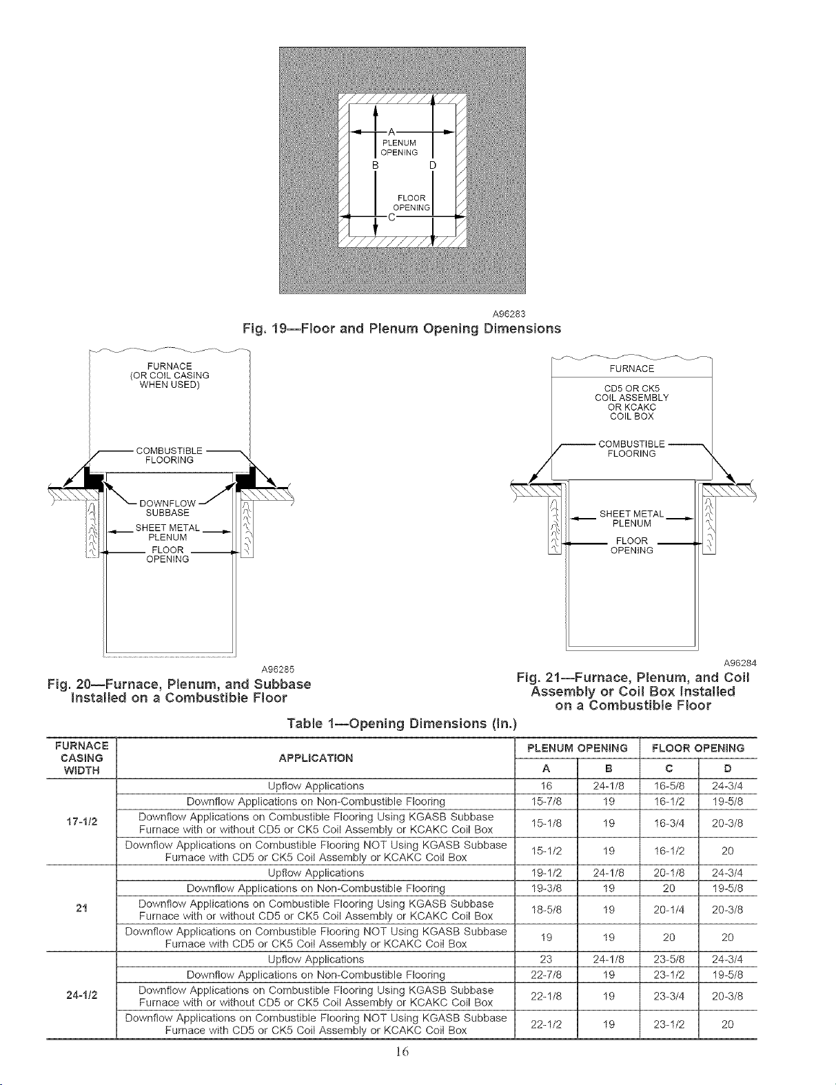
1 Determine application being installed from Table 1
2 Construct hole in floor per dimensions specified in Table 1
and Fig 19.
3 Consm/ct plenum to dimensions specified in Table 1 and Fig.
19.
4 If downflow subbase (KGASB) is used, install as shown in
Fig. 20
If coil assembly CD5 or CK5 or (?oil Box K(AK( is used,
install as shown in Fig 21.
NOTE: Remove fhmace perforated discharge duct flanges when
they interfere with mating flanges on coil on downflow subbase.
To remove f_amace perforated discharge duct flange, use hand
seamers, wide duct pliers or duct flange tool to bend flange back
and forth until it breaks off, Be carefid of sharp edges. (See Fig.
22.)
15
Page 16
A96283
Fig. 19--Floor and Plenum Opening Dimensions
FURNACE
(OR COiL CASING
WHEN USED)
FLOORING
SUBBASE
SHEET METAL
PLENUM
-- FLOOR --
OPENING
A96285 A96284
FURNACE
CD5OR CK5
COILASSEMBLY
OR KCAKC
COILBOX
FLOORING
SHEET METAL._
PLENUM
__ FLOOR __
OPENING
Fig. 20--Furnace, Plenum, and Subbase Fig. 21--Furnace, Plenum, and Coil
Installed on a Combustib{e Floor Assembly or Coi! Box Installed
on a Combustible Floor
Tab{e 1--Opening Dimensions (In.)
FURNACE
CASING
APPUCATION
WIDTH
Upftow Applications 16-5/8
Downflow Applications on Non-Combustible Flooring 16-1/2
17olt2 Downflow Applications on Combustible Flooring Using KGASB Subbase 16-3/4
Furnace with or without CD5 or CK5 Coil Assembly or KCAKC Coil Box
Downflow Applications on Combustible Ftooring NOT Using KGASB Subbase
Furnace with CD5 or CK5 Coil Assembly or KCAKC Coil Box
Upflow Applications 20-1/8
Downflow Applications on Non-Combustible Flooring 20
21 Downflow Applications on Combustible Flooring Using KGASB Subbase 20-1/4
Furnace with or without CD5 or CK5 Coil Assembiy or KCAKC Coil Box
Downflow Applications on Combustible Flooring NOT Using KGASB Subbase
Furnace with CD5 or CK5 Coit Assembly or KCAKC Coil Box
Upftow Applications 23-5/8
Downflow Applications on Non-Combustible Flooring 23-1/2
24o112 Downflow Applications on Combustible Flooring Using KGASB Subbase 23-3/4
Furnace with or without CD5 or CK5 Coil Assembly or KCAKC Coil Box
Downflow Applications on Combustible Ftooring NOT Using KGASB Subbase
Furnace with CD5 or CK5 Coil Assembly or KCAKC Coil Box
PLENUM OP_=N_NG
A B
16 24-1/8
15-7/8 19
15-1/8 19
15-1/2 19
19-1/2 24-1/8
19-3/8 19
18-5/8 19
19 19
23 24-1/8
22-7/8 19
22-1/8 19
22-1/2 19
FLOOR OPENING
C
D
24-3/4
19-5/8
20-3/8
16-1/2
20
24-3/4
19-5/8
20-3/8
20
20
24-3/4
19-5/8
20-3/8
23-1/2
20
16
Page 17

DISCHARGE DUCT
FLANGE
NO
YES
--9 UNIT MAY NOT OPERATE
Failure to fbllow this caution may result in intem_ittent unit
operation or perfbna_ance satisfaction
Do not bend duct flanges inward as shown in Fig. 22. This
will affect airflow across heat exchangers and may cause limit
cycling or premature heat exchanger failure. Remove duct
flange completely or bend it inward a minimum of 210 ° as
shown in Fig. 22.
/
210°
MIN
/
Fig. 22--Duct Flanges
YES
A93029
Step 3--hstaHation in Horizontal Applications
These t:m'naces can be installed in either horizontal left or right
discharge position. In a crawlspace, furnace can either be hung
from floor joist or installed on suitable blocks or pad. Furnace can
be suspended flora each corner by hanger bolts and angle iron
supports. (See Fig. 23.) Cut hanger bohs (4 each 3igoin. all-thread
rod) to desired length. Use 1 X 3/8-in. flat washers. 3/g-in.
tockwashers, and 3/8oin. nuts on hanger rods as shown in Fig. 23.
Dimples are provided for hole locations. (See Fig. 2.)
ANGLE
IRON OR
EQ
(B)
(A) ROD LOCATION
USING DIMPLE
LOCATORS
(SEE DIMENSIONAL
DWG FOR
LOCATIONS)
(A) PREFERRED ROD LOCATION
(B) ALTERNATE ROD LOCATION
II
II
II
II
I
I
A:: MAX
318-1N.
& WASHER (4)
REQD PER ROD
NOTES: 1. A 1 In. clearance minimum between top of
furnace and combustible material.
2. The entire length of furnace must be
supported when furnace is used in horizontal
position to ensure proper drainage.
Fig. 23--Crawlspace Horizonta{ Application
17
(B) ALTERNATE SUPPORT
LOCATION FROM BACK
ALTERNATE SUPPORT
LOCATION 4-IN. MIN
8-IN. MAX
A93304
Page 18

UNIT MAY NOT OPERATE
Failure to follow this caution may result in intemxittent unit
operation or performance satisfaction
The entire length of furnace MUST be supported when
fiu'nace is used in a horizontal position to ensure proper
draining. When suspended, bottom brace supporq_s sides and
center blower shelf When unit is supported from the ground,
blocks or pad should support sides and center blower shelf
area.
Step 4--Ak Duets
GENERAL REQUIREMENTS
The duct system should be designed and sized according to
accepted national standards such as ff*ose published by: Air
Conditioning Cormactors Association (ACCA), Sheet Metal and
Air Conditioning (ontractors National Association (SMACNA) or
American Society of Heating, Refl'igerating and Air (onditioning
Engineers (ASHRAE) or consult The .4it 5) stems Design G_ide-
lines reference tables available from your local distributor. The
duct system should be sized to handle the required system design
(FM at the design static pressure.
When a f\lrnace is installed so that tl_e supply ducts car D- air
circulated by the furnace to areas outside the space containing the
fhrnace, the return air must also be handled by a duct(s) sealed to
the furnace casing and terminating outside the space containing the
fhrnace.
Secure ductwork with proper fasteners for type of ductwork used.
Seal supply- and return-duct connections to fhrnace with code
approved tape or duct sealer.
Flexible connections should be used between ductwmk and
fhrnace to prevent transmission of vibration. Ductwork passing
through unconditioned space should be insulated to enhance
system performance. When air conditioning is used, a vapor
barrier is recommended.
Maintain a l-in. clearance fi'om combustible materials to supply air
ductwork fbr a distance of 36 in. horizontally fiom the furnace. See
NFPA 90B or local code fbr fhrther requirements.
For a fhmace not equipped with a cooling coil, the outlet duct shall
be provided with a removable access panel. This opening shall be
accessible when the Furnace is installed and shall be of such a size
that the heat exchanger can be viewed for possible openings using
light assistance or a probe can be inserted for sampling the air
stream. The cover attachment shall prevent leaks.
DU( TWORK A( OUSTICAL TREATMENT
Metal duct systems that do not have a 90 degree elbow and 10 ft
of main duct to the first branch take-off may require internal
acoustical lining As an ahernafive, fibrous ductwork may be used
if constructed and installed in accordance with the latest edition of
SMACNA construction standard on fibrous glass ducts Both
acoustical lining and fibrous ductwork shall comply with NFPA
90B as tested by UL Standard 181 fbr Class 1 Rigid air ducts.
SUPPLY AIR (ONNECTIONS
Epflow Furnaces
Connect supply-air duct to 3/4-in flange on fhmace supply-air
outlet. The supply-air duct attachment must ONLY be connected
to furnace supply-/outlet-air duct flanges or air conditioning coil
casing (when used) DO NOT cut main fhmace casing to attach
supply side air duct, humidifier, or other accessories. All accesso-
ries MUST be connected external to ft_rnace main casing
Downflow Furnaces
(onnect supply-air duct to supply-air opening on fhrnace. The
supply-air duct attachment must ONLY be connected to furnace
supply/outlet or air conditioning coil casing (when used), when
installed on non-combustible material. When installed on combus-
tible material, supply-air duct attachment must ONLY be con-
nected to an accessow subbase or Factory approved air condition-
ing coil casing. DO NOT cut main fk/rnace casing to attach supply
side air ducL humidifier, or other accessories All accessories
MUST be connected external to fhrnace main casing. Supply air
opening duct flanges must be modified per Fig. 22.
Horizontal Furnaces
Connect supply-air duct to supply air opening on filrnace. The
supply-air duct attachment must ONLY be connected to furnace
supply/outlet or air conditioning coil casing (when used) D() NOT
cut main furnace casing to attach supply side air duct, humidifier,
or other accessories. All accessories MUST be connected external
to fhrnace main casing.
RETURN AIR CONNECTIONS
FIRE HAZARD
Failure to %11ow this warning could result in fire, personal
injury, or death
Never connect return-air ducts to the back of the furnace
Return-air duct connections on fire, ace side(s) permitted in
upflow applications only
Upflow Furnaces
The return-air duct must be connected to bottom, sides (left or
right), or a combination of bottom and side(s) of main furnace
casing Bypass humidifier may be attached into unused side return
air portion of the ftmaace casing. DO NOT connect any portion of
return-air duct to back of fhmace casing.
Downflow and Horizontal Furnaces
The return-air duct must be connected to return-air opening
provided. DO NOT cut into casing sides or back to attach any
portion of return-air duct. Bypass humidifier connections should
be made at dtlctwork or coil casing sides exterior to furnace.
Step 5--FHter Arrangement
FIRE, CARBON MONOXIDE AND POISONING
HAZARD
Failure to follow this warning could result in fire, personal
injury or death.
Never operate unit without a filter or with filter access door
removed.
The air filter arrangement will vary due to application, furnace
orientation., and filter type. The filter may be installed in an
external Filter/Media cabinet (if provided) or the furnace blower
compartment Factory supplied washable filters are shipped in the
blower compartment
If a factory-supplied external Filter/Media cabinet is provided,
instructions for its application, assernbly, and installation are
packaged with the cabinet. The Filter Media cabinet can be used
with the Factory-supplied washable filter or a fhctow-specified
high-efficiency disposable filter (see cabinet instructions).
18
Page 19

RETAINER
\
A93045
Fig. 24_FiRer Installed for Side Inlet
If installing the filter in the f:urnace blower compartment, deter-
mine location for filter and relocate filter retaining wire, if
necessary. See Table 2 to determine correct filter size for desired
filter location. Table 2 indicates filter size, location, and quantity
shipped with this iqm_ace. See Fig. 2 for location and size of
bottom and side return=air openings.
171/2-1N. WIDE
CASINGS ONLY:
INSTALL FELD-SUPPLIED
FILTER FILLER STRIP
UNDER FILTER.
24 1/2"
rt4; 4
21-IN.WIDE
CASINGS ONLY:
SUPPORT RODS (3)
EXTEND 1/4" ON EACH
SIDE OF FILTER AND
REST ON CASING FLANGE
CUTS AND ABRASION HAZARD
Failure to %llow this caution may result in minor personal
injury
Use care when cutting support rods in filters to protect against
flying pieces and sharp rod ends. Wear safety glasses, gloves,
and appropiate protective clothing
UNIT MAY NOT OPERATE
Failure to follow this caution may result in intem_ittent unit
operation or peribm_aace satisfaction.
For airflow requirements above 1800 CFM, see Air Deliver-
table in Product Data literature fbr specific use of single side
inlets. The use of both side inlets, a combination of 1 side and
the bottom, or the bottom only will ensure adequate return air
openings for airflow requirements above 1S00 CFM.
NOTE: Side return-air openings can ONLY be used in UPFLOW
configurations. Install filter(s) as shown in Fig. 24.
For bottom return-air applications, filter may need to be cut to fit
some I_urnace widths. Install filter as shown in Fig. 25.
NOTE: Remove and discard bottom closure panel when bottom
inlet is used,
Step 6--Bottom Closure Panel
These fire, aces are shipped with bottom closure panel installed in
bottom return-air opening. This panel MUST be in place when side
remm air is used.
TaNe 2--FHter Information
AIR FILTER LOCATED BN BLOWER COMPARTMENT
Furnace Filter Size (In.) Filter Type
Casing Framed
Width 0n.} Side Return Bottom Return
17-112
21
24-1/2
* Filters may be field modified by catting filter material and support rods(3) in
filters. Alternate sizes can be ordered from your distributor or dealer
? Factory-provided with furnace.
(1)16X25X11- (1) 16X25X11- Cteanable
(1) 16 X25X 1" (t) 20 X 25 X 11. Cteanable
(1 or 2) 16X25X 1" (1) 24X25X 11- Cteanable
WASHABLE
FILTER
\
\
FILTER RETAINER
SUPPORT
FILTER
A00290
Fig. 25--Bottom FHter Arrangement
To remove bottom closure panel, per%tin %llowing:
1 Tilt or raise I_urnace and remove 2 screws iaolding fi'ont filler
panel. (See Fig. 26.)
2. Rotate fi'ont filler panel downward to release holding tabs.
3. Remove bottom closure panel.
4. Reinstall front filler panel and screws.
Step 7--Gas Piping
Gas piping must be installed in accordance with national and local
codes. Refer to NFGC in tiae US Canadian installations must be
made in accordance with NSCNGPI( and all authorities having
jurisdiction. Gas supply line should be a separate line 1atoning
directly fiom meter to t:m'nace, if possible. Ref)r to Table 3 %r
recommended gas pipe sizing. Risers must be used to connect to
£umace and to meter. Support all gas piping with appropriate
straps, hangers, etc. Use a minimun_ of 1 hanger every 6 t't. Joint
compound (pipe dope) should be applied sparingly and only to
male threads of joints. Pipe dope must be resistant to propane gas.
19
Page 20

BOTTOM
CLOSURE
PANEL
Z FRONT FILLER
PANEL
Fig. 26--Removing Bottom Closure Panel
Tab{e 3--Maximum Capacity of Pipe*
NOMINAL
IRON
PiPE
SRZB
(IN.)
1/2
3/4
1
1-1/4
1-112
Cubic ft of gas per hr for gas
a pressure drop of 0.5-in. wc
Table 9-2 NFPA 54-2002
--F FIRE OR EXPLOSION HAZARD
Failure to %l]ow this warning could result in fire, explosion,
personal injury, or death
Connect gas pipe to f_lmace using a backup wrench to avoid
damaging gas controls
Gas valve shutoff switch MUST be f_lcing fbp,vard or tilted
upward
Never purge a gas line into a combustion chamber. Never
test for gas leaks with an open flame. Use a commercially
available soap solution made specifically for the detection of
leaks to check all connections
Use proper length of pipe to avoid stress on gas control
manifbld
- If a flexible connector is required or allowed by authori V
having jurisdiction, black iron pipe shall be installed at
t\u'nace gas valve and extend a mininmm of 2 in. outside
furnace casing.
INTERNAL
DRAMETER
(IN.)
0.622
0.824
1.049
1.380
1.610
LENGTH OF PIPE (FT)
10 20 30 40 50
175 120 97 82 73
360 250 200 170 151
680 465 375 320 285
1400 950 770 660 580
2100 1460 1180 990 900
_ressures of 05 psig(14-in, wc) orless, and
based on a 0.60 specific gravity gas)Ref:
A93047
GAS
SUPPLY
MANUAL _/ ]]
IR 00,R 0 f
A93324
Fig. 27--Typica! Gas Pipe Arrangement
An accessible manual shutoff valve MLST be installed external to
ft_rnace casing and within 6 ft of _i_rnace. A 1i8oin. NPT plugged
tapping, accessible _br test gauge connection, MUST be installed
immediately upstream of gas supply connection to ftlrnace and
downstleam of manual shutoff valve.
NOTE: The gas valve inlet pressure tap connection is suitable to
use as test gauge connection providing test pressure DOES NOT
exceed maximum 05 psig (14oin wc) stated on gas valve (See
Fig 62.)
Piping should be pressure and leak tested in accordance with
NFGC in the United States or NSCNGPIC in (anada, local, and
national plumbing and gas codes before the furnace has been
connecte& If pressure exceeds 05 psig (14oin wc), gas supply
pipe must be disconnected fiom ftmaace and capped be_bre
pressure test
If test pressure is equal to or tess than 05 psig ( 14oin wc), turn off
electric shutoff switch located on gas valve before test. It is
recommended that ground joint union be loosened before pressure
testing. After all connections have been made, purge lines and
check for leakage at furnace prior to placing it into service.
The gas supply pressure shall be within the maximum and
minimum inlet supply pressures marked on the rating plate with
the t_/mace burners ON at HI-HEAT and OFF.
Step 8--Electrical Connections
See Fig 28 for field wiring diagram showing typical field 115-v
and 24-v wiring Check all I:_cto_- and field etectIical connections
for tightness
Install a sediment trap in riser leading to _lmace. Trap can be
installed by connecting a tee to riser leading to furnace so
straight-through section of tee is vertical Then connect a capped
nipple into lower end of tee. Capped nipple should extend below
level of gas contlols. Place a ground joint union between gas
control manifold and manual gas shutoff valve. (See Fig 27.)
ELECTRICAL SHOCK HAZARD
Failure to follow this warning could result in personal injury
or death.
Blower access door switch opens 115-v power to furnace
contlol. No component operation can occur. Do not bypass or
close switch with panel removed.
2O
Page 21

Table 4--EiectricN Data
UNIT
SIZE
040-14 15
060-14 15
080-14 15
080-20 20
100-20 20
t20-80 20
* Permissible limits of voltage range at which unit will operate satisfactorily.
T Unit ampadty = 125 percent of largest operating component's full load amps plus 100 percent of aH other potential operating components' (EAC, humidifier, etc.) fun
load amps
$ Length shown is as measured 1 way along wire path between unit and service panel for maximum 2 percent voltage drop.
*_ Time-delay type is recommended.
115-V
SINGLE
PHASE
VOLTS--
HERTZ--
PHASE
115--60--1
115--60--1
115--60--1
115--60--1
115--60--1
115--60--1
OPERATING
VOLTAGE RANGE
Maximum* Minimum*
127 104
127 104
127 104
127 104
127 104
127 104
MAXIMUN
UNiT
AMPS
8.9
8.9
8.9
13.8
13.8
13.8
MINIMUM
WRRE
SIZE
14
14
14
12
12
12
THERMOSTAT
TERMINALS FIELD-SUPPLIED
MAXBMUM WIRE
LENGTH (FT)_:
31
31
31
32
32
32
.... FIELD 24-V WIRING
.... FIELD 115-,208/230-, 460-V WIRING
-- FACTORY 24-V WIRING
-- FACTORY 115-,208/230-, 460-V WIRING
DISCONNECT
[',_AXJMUM FUSE OR
CKT BKR AMP$**
208/230- OR
460-V
208/230-V
SINGLE
PHASE
Fig. 28--Heating and Cooling Application Wiring Diagram
[TNIT MAY NOT OPERATE
Failure to %llow this caution may result in intem_ittent unit
operation,
Furnace control must be grounded for proper operation or
control will tock out, (ontrol is grounded through
green yellow wire connected to gas valve and burner box
screw,
115-V WIRING
Be%re proceeding with electrical cormections, make certain that
voltage, fi'equency, and phase con'espond to that specified on
furnace rating plate, Also, check to be sure that sma'ice provided
by power supply is sufficient to handle load imposed by this
equipment Refer to rating plate or Table 4 for equipment electrical
specifications
CONDENSING
UNIT
NOTES:
1. Connect Y or Y/Y2 terminaI as shown for proper cooling operation.
2. Proper polarity must be maintainedfor 115-v wiring.
3. Use W2 with 2-stagethermostat when zoning.
4. Ifany of the original wire, as supplied, must be replaced, use
same type or equivalent wire.
5. Some thermostats require a "C" terminal connection as shown.
ELECTRIC
DISCONNECT
SWITCH
®
Fig. 29--Disconnect Switch and Furnace
Make al! electrical connections in accordance with National
Electlical Code (NEC) ANSI NFPA 70-2002 and any local codes
or ordinances that might apply For (anadian installations, all
electlical connections must be made in accordance with Canadian
Electrical (7ode CSA C22,1 or authorities having jurisdiction
Field=supplied wiring shall conform with the limitations of 63_>F
(33°C) rise
2i
A98325
A93033
Page 22

ALTERNATE --
FIELD
LOCATION
(_J f
f/F FACTORY
Y
Fig. 30--Relocating J-Box
Use a separate branch electrical circuit containing a properly sized
fhse or circuit breaker for this furnace. See Table 4 for wire size
and fuse specifications. A disconnecting means nrust be located
within sight t)om and readily accessible to fi/rnace.
NOTE: Proper polari V must be maintained for l15=v wiring. If
polarity is incorrect, _:i/mace contlol stares code indicator light will
flash rapidly and _m_ace will NOT operate.
--€ FIRE HAZARD
Failure to fbllow this warning could result in intermittent
operation or performance satisbaction
Do not connect aluminum wire between disconnect switch
and furnace. Use only copper wire (See Fig. 29.)
ELECTRICAL SHOCK AND FIRE HAZARD
Failure to follow this warning coud result in electrical shock,
fire, or death.
The cabinet MUST have an uninterrupted or unbroken ground
according to NEC ANSI NFPA 70-2002 and Canadian Elec-
trical (?ode CSA C22.1 or local codes to minimize personal
injuv if an electrical _i_ult should occur This may consist of
electrical wire or conduit approved for electrical ground when
installed in accordance with existing electrical codes. Do not
use gas piping as an electrical ground.
J-Box Relocation
1. Remove 2 screws holding auxiliary J-box. (See Fig 30.)
2. Rotate J-box 180 ° and attach box to left sidQ using holes
provided.
INSTALLED
LOCATION
A00212
--€ FIRE OR ELECTRICAL SHOCK HAZARD
Failure to [bllow this warning could result in intem_ittent unit
operation or per_bm_ance satisfaction.
If manual disconnect switch is to be mounted on furnace,
select a location where a drill or £hstener will not contact
electrical or gas components.
(ONTINUOUS FAN ((F) SETUP SWIT(HES
The (F setup switches are used to select desired airflow when
thermostat is in continuous fire mode or to select tow-cooling
airflow fbr two-speed cooling units This setup fcatme allows
continuous fhn airflow or low-cooling airflow to be adjusted. To
set desired continuous ltan airflow or low-cooling airflow:
1. Remove main fhmace door and blower access panel.
2. Locate (F setup switches on fi/mace control. (See Fig 320
3. Detem_ine desired continuous fan airflow or tow-cooling
airflow
4. Use Fig. 58 or wiring schematic to determine proper setup
position of CF switches (See Fig. 3! and 59)
5. Replace main l:urnace door and blower access panel
SET[P SWITCHES (SWI)
The fimaace control }*as 8 setup switches that may be set to meet
the application requirements. Position these setup switches tbr the
appropriate requirement.
1. Remove main thmace doo* and blower access panel.
2. Locate setup switches on furnace control. (See Fig. 32)
3. See Table 9 fbr setup switch description (See Fig. 31 and 59)
4. Replace main l:urnace door and blower access panel
NOTE: Ifa bypass hun_idifier is used, setup switch SW1-3 (Low
HEAT Rise Adjust) should be in ON position. This compensates
for the increased temperature in return air resulting fi'om bypass
NOTE: If modulating dampers are used, blower motor automati=
cally compensates for modulating dampers. It" manual disconnect
switch is to be mounted on fi/rnace, setect a location where a drill
or t_stener will not contact electrical o1" gas components
24=V WIRING
Make field 24-v thermostat connections at 24=v tem_inal block on
furnace control. ¥ wire from thermostat MIST be connected to
YY2 terminal on control, as shown in Fig. 28, for proper cooling
operation. The 24=v terminal block is marked _br easy connection
of field wiring. (See Fig. 32.) The 24=v circuit contains a 3=amp,
automotive-type *:use located on [hmace control. (See Fig. 32.)
Any electrical shorts of 24=v wiring during installation, service, or
maintenance may cause £hse to blow. If fuse replacement is
required, use only a *:use of identical size (3 amp) and type. The
furnace control will flash stares code 24 when _i/se needs replace-
nlent
NOTE: Use AWG No. 18 color-coded copper thermostat wire _:br
tengths up to 100 R. For wire lengths over 100 ft, use AWG No.
1d wire.
22
Page 23

NOTE: For additional thermostat connection diagrams, reference
Fig 54o61
AC( ESSORIES
1. Electronic Air Cleaner (EAC)
The furnace control EAC terminals are energized with 115v
(1.0=amp maximum) during blower operation.
Connect an accessory Electronic Air Cleaner (if used) using
1/4-in. female quick connect terminals to the two male 1/4=in.
quick-connect terminals on the control board marked EAC-1
and EAC=2. The terminals are rated fbr 115VAC, 1.0 amps
maximum and are energized during blower motor operation.
(See Fig. 32.)
2. Humidifier (HUM)
Connect an accessol T 24 VAC, 0.5 amp maximum humidifier
(if used) to the 1/4-in. male quickoconnect HUM terminal and
Co,,>24V screw tem_inal on the control board thet_nostat strip.
The HUM terminal is energized when blower is energized in
heating. (See Fig. 32.)
-->
[NIT DAMAGE HAZARD
Failure to follow this caution may result in unit component
damage.
DO NOT connect fhrnace control HUM terminal to HUM
(humidifier) terminal on Tlaermidistat TM, Zone (ontIoller or
similar device. See Them_idistag xi, Zone Controller, ffiermo°
stat, or controller manui:acmrer's instructions for proper
connection.
Step 9--Direct Venting
The 58MVP furnaces require a dedicated (one 58MVP furnace
only) direct=vent system. In a direct-vent system, all air for
combustion is taken directly fi'om outdoor atmosphere, arid all flue
gases are discharged to outdoor atmosphere.
REMOVAL OF EXISTING FURNACES FR()M
(OMMON VENT SYSTEMS
When an existing Category I furnace is removed or replaced, the
original venting system may no longer be sized to properly vent
the remaining attached appliances. An improperly sized CategoQ"
I venting system could cause the formation of condensate in d_e
furnace and vent, leakage of condensate and combustion products,
and spillage of comhustion products into the living space, etc.
CARBON MONOXIDE POISONING HAZARD
Failure to fbllow the steps outlined below for each appliance
connected to the venting system being placed into operation
could result in carbon monoxide poisoning or death.
The fPllowing steps shall be followed fbr each appliance
connected to the venting system being placed into operation,
while all other appliances connected to the venting system are
not in operation:
1. Seal any unused openings in venting system.
2. Inspect d_e venting system for proper size and horizontal
pitch, as required in the National Fuel Gas (;ode, ANSI
Z223AiNFPA 54 or dae CSA B149.1. Natural Gas and
Propane Installation Code and these instructions. Deter-
mine that there is no blockage or restriction, leakage,
corrosion and other deficiencies, which could cause an
urisafc condition.
3. As fhr as practical, close all building doors and windows
and all doors between the space in which the appli=
ance(s) connected to the venting system are located and
other spaces of the building.
4. Close fireplace dampers.
5. Turn on clothes dcgers and any appliance not connected
to the venting system. Turn on any exhaust fans, such as
range hoods and bathroom exhausts, so they are opera°
ing at maximum speed. Do not operate a summer
exhaust fhn.
6. Follow the lighting instructions. Place the appliance
being inspected into operation. Adjust the thermostat so
appliance is operating continuously.
7. Test for spillage fiom draft hood equipped appliances at
the &aft hood relief opening after 5 minutes of main
burner operation. Use d_e flame of a match or candle.
8. If improper venting is observed during any of the above
tests, the venting system must be corrected in accordance
with the National Fuel Gas (7ode, ANSI Z223AiNFPA
54 and/or CSA B 149.1, Natural Gas and Propane Instal°
tation Code,
9 After it has been dete*mined that each appliance con=
nected to the venting system properly vents when tested
as outlined above, return doors, windows, exhaust rims,
t_replace dampers and any other gas°fired burning appli°
ante to their previous conditions of use
Vent system or vent connectors may need to be resized. For any
other appliances when resizing vent systems or vent connectors,
system or connector must be sized to approach minimum size as
determined using appropriate vent sizing table %und in the NFGC
or NSCNGPIC
COMBUSTION=AIR AND VENT PIPING
General
Combustion_air and vent pipe, fittings, primers, arid solvents must
con%tin to American National Standards Institute (ANSI) stan-
dards arid American Society %r Testing and Materials (ASTM)
standards. See Table 5 for approved materials for use in the U.S.A.
See Table 7 fbr maximum pipe lengths and Fig. 37, 38, 39, 40, and
41 fk_r exterior piping an'angements.
23
Page 24

m m m m m m
SW1 7r_
CONNECTION DIAGRAM
m
m m m m
TO 115VAC FI_LD-D)SCONNECT SVMTCH SCHEMATIC DIAGRAM
_ _HS[R PL23 H8[ L2
PL3 PL13
MODEt D_ _= _ _ _ _ _
4_
:00 0 ,050,225,225,225 /,4
5T08010( DEF 7002 875 1050 1225 1400 1750 1750
120 D_F 700 87_ 10_0 1_2_ 1400 17_0 2100 _
1 Det HtA/C irflow vhen, /Csw]t hesa !inOfF posi_on I I I I I I I I I I
2Det ,I.....• fanai12 ........ OF Mtch_ ar_in )FFposition [ _ PL12_ _zc_N II IU
d) D o D O D O
' I 91617 54321
I
v_r2 Yl DHUM G Com'_/_VlR STATUS _' RED_ -
AC ........................Cr_..................... "L __ _
ACR AirCo_dltic_-ingRelaySPST(NO) LED UghtEmittlngDiodeforStatusCodes _ UNC ON
E ACRDJ A_rCondiSoningRelayDe_eatJumper LGPS LowGasPfessuleSw_chSPST(NO)
BLWM Bowel Motor (ECM) LPS Low Heat PressureSwitch SPST(NO) O TERMINAL
CF Con_nuous Fan (Adjustable Airflow CFM) /s Limit Switch Auto Reset SPST(N C ) CONTROL TERMINAL
I A/C _rCond_ioning (AdjustableAirflow CFM) IND InductoHNote#7)
COMMR Communication Relay SPOT PCB Printed Cirr uR Board m
cPu Microprocessor / Cirr uitry PL1 12 Circuit Connector FACTORYPOWER
DHUM DHUM Connection (24VAC) PL2 4 CircuR HSi & IDM Connector
EAC 1 Electlonic Air Cleaner Connection PL3 4Circuit ECM BLWM Connector WIRING(115VAC)
(115VAC 10 Air pMax) PL4 4 Cirr uit Model Plug Connector
EAC 2 Bectronic Air Cleaner Connection (Common) PL7 4Circuit Communication Connector FACTORYCONTROL
FRS Flame Rollout SwRch Man Reset SPST(NC ) PL9 2 Cirr uR OAT Connector
FUSE Fuse 3 Amp Automotive Blade Type
Factory InstaJled
GV Gas Valve
I FSE Flame Roving Sensor Electrode
GVR Gas Va(ve Relay DPST (NO )
H_ High Heat Pessur_ Swmh SP3T(NO)
HPSR High Heat Ressure Swmh Relay SPST(NC)
HSIR Hot SurfaceIgniterRelay SPST(NO)
HUM 24VAC Humidifie_Connectic_ (05Amp Max)
HUMR HumidifierRela_ SPST(NO )
I HSI Hot Surt_ice Ign_el(115VAC)
IDM InducelDiaftMotel2 Speed, Shaded Pole
IDR Inducer Motor Relay SPST(NO)
IHI/LOR Induc_ Motel Speed Change R#]a_ SPDT
PLIO 2Circuit HSIConnector WIRING (24VAC)
PL11 IDM Connectc_ (12 CircuiQ FIELDCONTROL
PL12 1 CirruR Inductor Splice Connector -----
PL13 16 Circuit ECM Bbwef Ctd Coqlectof WIRING (24VAC)
PL14 5 Circuit ECM Blower Power Connector
SW11 Manual Switch Status Code Recall SPST(NO ) CONDUCTOR ON
SWl 2 ManuaISwl_ch LowHeat Only SPST(NO) CONTROL
SWl 3 Manual Switch Low Heat Rse Adj SPST(NO)
SWl 4 ManuaISwitdl Comtoft/Ef9ciency Adjustment, FIELDWIR]NG
SWl 5 Manual SWl_Ch Cooling CFM£on SPST(NO) SCREWTERMINAL
9¢/16 Manual Switch Component Test SPST(NO) EQUIPMENT
SW178 Manua( Switches Blowel OfFDelay SPST(NO)
9¢/41 Manual SwRch Twinning Main (OFF) / Sec (ON) GROUND
SPST(NO)
Fig. 31--Wiring Diagram A02291
NOTES:
Use o_ly cgagar wire belween the disconPecl _vitch and t he fi_mace junclion box (J B}
This w_re n_ast be m_Pected to furnace sleet metal for coniro( to prove flame
f If any °f the °rg'n_ equim_eni w're isreplace_ use w're rated f°r f05°C _1
i Symbols ale eleutnc_ _ep_esental_on only
Sdid liPes ins_e PCB are pnnted circuit board con@dolors al_d are _ot included in legand
i] Rep)ace only w_f!_ a3 amp fuse -_-
Inductc{ is used with 3/4 hp aid 1 hp ECM Bb_er motors
Bbwer offdela_z gas heaing selec_ons ale (90,120,189,180) secords, cooling or Ileat pump
90 secongs or 5 secol-ch wt-en dehurT_dify ca))is active
_] Factory ...... _edwJ-en(LGPS)notused _ I
f 0 Ignition lockout _ll OCCurafter four consecutrve unsuccessfi_l tn_s for ignition Control _qi
auto-Festal after three hours
f I A_ of the 5 wires @own v4 hin t he N[UTRAL L2 box Ca1 be conPeGed to any terminal wit hin the box
Page 25

MODEL PLUG
CONNECTOR
SW1 SETUP
SWITCHES AND
BLOWER OFF-
DELAY
AIR CONDITIONING
(A/C) AIRFLOW
SETUP SWITCHES
24-V THERMOSTAT
TERMINALS
STATUS AND COMM
LED LIGHTS
3-AMP FUSE
COMMUNICATION CONTINUOUS FAN FUTURE
CONNECTOR (CF) AIRFLOW APPLICATIONS
m_ COMM
ECZZZ]
FUSE3-AMP
SEC 2 SEC 1
SETUP SWITCHES
m_
ACRDJ
D
[]
[]
[]
[]
[]
[]
HUMIDIFIER
J
/ TERMINAL (24-VAC
05 AMP MAX
ACRDJ-AIR
CONDITIONING
RELAY DISABLE
JUMPER
O_" FLASH
UPGRADE
CONNECTOR
(FACTORY
ONLY)
\
PL3-ECM BLOWER
HARNESS
CONNECTOR
TRANSFORMER 24-VAC
CONNECTIONS
115-VAC (L2) NE UTRAL
CONNECTIONS
PL1-LOW VOLTAGE MAIN
HARNESS CONNECTOR
(115-VAC10 AMP MAX}
EAC-1 TERMINAL _%X
.............EAC I--[--I.2
_ LO
115-VAC(L1)LINE PL2- HOTSURFACE
VOLTAGE CONNECTIONS IGNITER& INDUCER
MOTORCONNECTOR
Fig. 32--Control Center
TABLE 5--APPROVED COMBUSTION-AIR AND VENT PIPE, FITTING AND CEMENT MATERIALS
ASTM SPECBFRCATION
(MARKED ON MATERIAL)
D1527
D1785
D2235
D2241
D2466
D2468
D2564
D2G61
D2G65
F438
F441
F442
F493
FG28
F656
F891
MATERIAL PIPE FITTINGS SOLVENT CEMENT AND PRBMERS
ABS Pipe --
PVC Pipe --
For ABS -- --
Solvent
Cement
PVC Pipe --
PVC -- Fittings
ABS -- Fittings
For PVC -- --
Solvent
Cement
ABS Pipe Fittings
PVC Pipe Fittings
CPVC -- Fittings
CPVC Pipe --
CPVC Pipe --
For CPVC -- --
Solvent
Cement
ABS Pipe --
For PVC -- --
Primer
PVC Pipe --
DESCRBPTION
Schedule-40
Schedule-40
SDR-21 & SDR-26
Schedule-40
Schedule-40
DWV at Schedule-40 IPS sizes
Schedule-40
Schedule-40
Cellular Core DWV at Schedule-40 IPS sizes
Cellular Core Schedule-40 & DWV
A02278
For ABS
For PVC
DWV
SDR
For CPVC
For PVC
25
Page 26

_] VENT TERMINAL
(_AIR SUPPLY INLET
AREAWHERE TERMINAL IS NOT PERMITED
item Clearance Description
A C_earance above grade, veranda, porch, deck, balcony, or
anticipated snow level
B Clearance to a window or door that may be opened
C
Clearance to a permanently closed window
D
Vertical clearance to a ventilated soffit located above the
terminal within a horizontal distance of 2'(61cm) from the
centedine of the terminal
E
Clearance to an unventilated soffit
F
Clearance to an outside corner
G
Clearance to an inside corner
H
Clearance to each side of the centedine extended above
electrical meter or gas service regulator assembly
I
Clearance to service regulator vent outlet
J
Clearance to non-mechanical air supply inlet to building or
the combustion air inlet to any other appliance
K
Clearance to a mechanical air supply inlet
L
Clearance under a veranda, porch, deck, or balcony
M
Clearance to each side of the centedine extended above or
below vent terminal of the furnace to a dryer or water heater
vent, or other appliance's direct vent intake or exhaust
Clearance to the vent terminal of adryer vent. 'water heater
vent, or other appliances direct vent intake or exhaust
Clearance from a plumbing vent stack
(1) In accordance with the current CSA Bf 49 1, Natural Gas and Propane Installation Code
(2) In accordance with the current ANSI Z223 I/NFPA 54, National Fuel Gas Code
# 18" (46cm)aboveroofsurface
+ Permitted only if veranda, porch, deck. or balcony is fully open on a minimum of two sides beneath the floor.
For clearances not specified in AN SI Z223 1/N FPA 54 or CSA B149 1, clearances shall be inaccordance with local installation codes and the requirements of the gas supplier and the
manufacturer's installation instructions
Notes:
1 The vent for this appliance shall not terminate
a. Over public waikways; or
b Near soffit vents or crawl space vents or other areas where condensate or vapor could create a nusaince or hazard or property damage; or
c. Where condensate vapor could cause damage or could be detrimental to the operation of regulators, relief valves, or other equipment
2 When locating vent terminations, consideration must be given to prevailing winds, location, and other conditions which may cause recircula6on of the combustion products of adjacent vents
Recirculafion can cause poor combustion, inlet condensate problems, and accelerated corrosion of the heat exchangers
3 Avoid venting under a deck or large overhang Recirculation could occur and cause performance or system problems
12" (3Ocm) #
12" (36 cm) for appliances > 10.660 Btuh (3 kW)
and < 100,600 Btuh (30 kW), 36"
(91 cm) for appfiances > 160,600 Btuh (30 kW)
3' (9t cm) within 15'(45 m) above the meter/regulator
assembly
3' (91 cm)
9" (23 cm)for appliances > 10.000 Btuh (3 kW) and
< 100,O00 Btuh (3OkW) and < 56,000 Stuh (15 kW), 12"
(36 cm) for appliances > 56,000 Btuh (15 kW)
6' (1.83 m)
12" (30 cm) +
12" (30 cm)
3' (9t cm)
3' (91 cm)
Canadian Installation (1)
12" (30 cm)
9"(23 cm) for appliances > 10,006 Btuh (3 kW)
and < 50.066 Btuh (15kW), 12"
(30 cm) for appliances > 56,060 Btuh (15 kW)
3" (91 cm) within 15'(45 m) above the meter/regulator
assembly
9"(23 cm) for appliances > fO,0O0 Btuh (3 kW)
and < 50,000 Btuh (15kW), 12"
(30 cm) for appliances >56,000 Btuh (15 kW)
3" (91 cm) above if within 10"(3m)horizontaHy
12" (30 cm)
3" (91 cm)
3" (91 cm)
US Installation (2)
-_ Table 6--Direct Vent Termination Clearance
26
A04117
Page 27

In Canada, construct all combustion-air and vent pipes %r this unit
of CSA or UL( listed schedule-40 PVC, PV(-DWV or ABS-
DWV pipe and pipe cement. SDR pipe is NOT approved in
Canada
NOTE: Furnace corubustion-air and vent pipe connections are
sized for 2-in. pipe. Any pipe size change should be made outside
fmnace casing in vertical pipe. (See Fig. 33.) This allows proper
drainage of vent condensate.
Combustion-air and vent pipes must tem_inate together in same
atmospheric pressure zone, either through roof or sidewall (roof
tem_ination preferred), using accessory termination kit.
See Table 6 for required clearances.
Furnace combustion-air and vent pipe connections must be at-
tached as shown in Fig. 34. Combustion-air intake plug fitting and
inducer housing alternate vent cap may need to be relocated in
some applications.
NOTE: Slope combustion-air and vent pipes a mininmm of 1/4
in. per linear ft with no sags between hangers.
--9
MINOR PROPERTY DAMAGE
Failure to %llow this caution may result in water damage
from condensate dripping.
When combustion-air pipe is installed above a suspended
ceiling, pipe must be insulated with 3/8-in. thick Armaflex-
type insulation Combustion°air pipe should also be insulated
when it passes through a warn% humid space.
NOTS: Select 1vent pipe connection and
1 combustion-air pipe connection
AIR
COMBUSTION-AIR 7 COMBUSTION-AIR
UPFLOW
COMBUSTION-
AIR
VSNT
HORIZONTAL-LEFT DISCHARGE
NOTE: Select 1 vent pipe connection and
1 combustion-aB pipe connection
COMBUSTION- _ COMBUSTION-
AIR AiR
HORIZONTAL-RIGHT DISCHARGE
Fig. 34-=Combustion-Air and Vent Pipe
Connections
AIR
FLOW
DOWNFLOW
COMBUSTION-
VENT
AiR
A96187
[NIT MAY NOT OPERATE
Failure to follow this caution may result in intem_ittent unit
operation.
When vent pipe is exposed to temperatures below fi'eezing,
such as when it passes through an unheated space or when a
chimney is used as a raceway, pipe must be insulated as
shown in Table 8 with Armaflex-type insulation
FURNACE
(
NOT IN
HORIZONTAL
SECTION
TRANSITION IN
VERTICAL SECTION
A93034
Fig. 33--Combustion-Air and Vent Pipe Diameter
Transition Location and Elbow Configuration
UNIT CORROSION HAZARD
Excessive exposure to contaminated combustion air may
result in safety and perfbt_nance related problems.
Combustion air must not be taken flora inside structure
because that air is fiequently contaminated by halogens,
which include fluorides, chlorides, bromides, and iodides.
These elements are fbund in aerosols, detergents, bleaches,
cleaning solvents, salts, air f?esheners, adhesives, paint, and
other household products Locate combustion-air inlet as far
as possible from swimming pool and swimming pool pump
house,
FIRE AND EXPLOSION HAZARD
Failure to follow this warning could result in fire, property
damage, personal ir_jury_ or death.
Solvent cements are combustible. Keep away ti'om heat,
sparks, and open flame. Use only in well ventilated areas.
Avoid breathing in vapor or allowing contact with skin or
eyes.
CARBON MONOXIDE POISONING HAZARD
Failure to follow this warning could result in property
damage, pe*sonal il_iu*y, or death.
All combustionoair and vent pipes must be airtight and
watertight. Pipes must also tem_inate exactly as shown in Fig.
37, 38, 39, 40, or 41.
NOTE: The minimum combustion=air and vent pipe lengd_ (each)
for these fhmaces is 5 ft, Short pipe lengths (5=8 ft) may discharge
27
Page 28

ALTITUDE
0 to 2000
A_titude
2001 to 3000
A_titude
3001 to 4000
A_titude
4001 to 5000@
A_titude
5001 to 6000_
See notes on next page
UNIT
SRZE
040-14
060-14
080-14
080-20
100-20
120-20
Unit
Size
040-14
060-14
080-14
080-20
100-20
120-20
Unit
Size
040-14
060-14
080-14
080-20
100-20
120-20
Unit
Size
040-14
060-14
080-14
080-20
100-20
120-20
Unit
Size
040-14
060-14
080-14
080-20
100-20
120-20
Tab{e 7--Maximum Allowable Pipe Length (Ft)
TERMINATBON
TYPE
2 Pipe or 2-1n.
Concentric
2 Pipe or 2qn.
Concentric
2 Pipe or 2-In.
Concentric
2 Pipe or 2-tn.
Concentric
2 Pipe or 3qn.
Concentric
Termination
Type
2 Pipe or 2-tn.
Concentric
2 Pipe or 2-In.
Concentric
2 Pipe or 2qn.
Concentric
2 Pipe or 24n.
Concentric
2 Pipe or 3qn.
Concentric
Termination
Type
2 Pipe or 2qn.
Concentric
2 Pipe or 24n.
Concentric
2 Pipe or 2-in.
Concentric
2 Pipe or 2qn.
Concentric
2 Pipe or 3-in.
Concentric
Termination
Type
2 Pipe or 2-in.
Concentric
2 Pipe or 2qn.
Concentric
2 Pipe or 2-in.
Concentric
2 Pipe or 2qn.
Concentric
2 Pipe or 3-in.
Concentric
Termination
Type
2 Pipe or 2-in.
Concentric
2 Pipe or 2qn.
Concentric
2 Pipe or 2-in.
Concentric
2 Pipe or 2qn.
Concentric
2 Pipe or 3-in.
Concentric
PiPE DIAMETER
(IN.)*
1-1/2
2
1-1/2
2
1-1/2
2
2
2-1/2
2-1/2
3
3t
Pipe Diameter
(In.)*
1-1/2
2
1-1/2
2
1-1/2
2
2
2-1/2
3
3t
Pipe Diameter
(In.)*
1-1/2
2
1-1/2
2
1-1/2
2
2
2-1/2
3
3t
Pipe Diameter
(In.)*
1-1/2
2
1-1/2
2
1-1/2
2
2
2-1/2
3t
Pipe Diameter
(In.)*
1-1/2
2
1-1/2
2
1-1/2
2
2
2-1/2
3t
1 2 3 4 5 6
50 45 40 35 30 25
70 70 70 70 70 70
50 45 40 35 30 25
70 70 70 70 70 70
30 25 20 15 10 5
70 70 70 70 70 70
45 40 35 30 25 20
70 70 70 70 70 70
10 NA NA NA NA NA
35 30 15 NA NA NA
70 70 70 70 70 70
1 2 3 4 5 6
45 40 35 30 25 20
70 70 70 70 70 70
45 40 35 30 25 20
70 70 70 70 70 70
26 21 16 11 6 NA
70 70 70 70 70 70
40 35 30 25 20 15
70 70 70 70 70 70
31 26 12 NA NA NA
63 62 62 61 61 61
1 2 3 4 5 6
42 37 32 27 22 17
70 70 70 70 70 70
42 37 32 27 22 17
70 70 70 70 70 70
25 20 15 10 5 NA
70 70 70 70 70 70
38 33 28 23 18 13
70 70 70 70 70 70
29 24 10 NA NA NA
59 59 58 57 57 56
1 2 3 4 5 6
40 35 30 25 20 15
70 70 70 70 70 70
40 35 30 25 20 15
70 70 70 70 70 70
23 18 13 8 NA NA
70 70 70 70 70 68
36 31 26 21 16 11
70 70 70 70 70 70
56 55 54 53 52 52
1 2 3 4 5 6
37 32 27 22 17 12
70 70 70 70 70 70
37 32 27 22 17 12
70 70 70 70 70 70
22 17 12 7 NA NA
70 70 70 70 68 63
33 28 23 18 13 8
70 70 70 70 70 70
53 52 50 49 48 47
NUMBER OF 90° ELBOWS
Number of 90 ° Elbows
Number of 90 ° Elbows
Number of 90 ° Elbows
Number of 90 ° Elbows
28
Page 29

Tab{e7--MaximumAHowablePipeLength(Ft) Continued
ALTITUDE
8001 to 7000_
A_titude
7001 to 80005
A_titude
8001 to 9000_
A_titude
9001 to t0000_
* Disk usage--Unless otherwise stated, use perforated disk assembly (factory-supplied in loose parts bag)
1 Wide radius elbow
$ Vent sizing for Canadian installations over 4500 ft (1370m) above sea level are subject to acceptance by the local authorities having jurisdiction.
NA--Not Allowed; pressure switch will not make
NOTES:
1. Do not use pipe size greater than those specified in table or incomplete combustion, flame disturbance, or flame sense lockout may occur.
2. Size both the combustion-air and vent pipe independently, determine the smallest diameter allowed by the table for each pipe, then use the larger diameter for both
pipes
3. Assume two 45 ° elbows equal one 90 ° elbow Long radius elbows are desirable and may be required in some cases
4. Elbows and pipe sections within the furnace casing and at the vent termination should not be included in vent length or elbow count.
5. The minimum pipe length is 5 fl for all applications
UNiT
SRZE
040-14
060-14
080-14
080-20
100-20
120-20
Unit
Size
040-14
060-14
080-14
080-20
100-20
120-20
Unit
Size
040-14
060-14
080-14
080-20
100-20
120-20
Unit
Size
040-14
060-14
080-14
080-20
100-20
120-20
TERMiNATiON
TYPE
2 Pipe or 2-In.
Concentric
2 Pipe or 2-In.
Concentric
2 Pipe or 2-In.
Concentric
2 Pipe or 2-In.
Concentric
2 Pipe or 3-In.
Concentric
Termination
Type
2 Pipe or 2-In.
Concentric
2 Pipe or 2-In.
Concentric
2 Pipe or 2-In.
Concentric
2 Pipe or 2-In.
Concentric
2 Pipe or 3-In.
Concentric
Termination
Type
2 Pipe or 2-In.
Concentric
2 Pipe or 2-In.
Concentric
2 Pipe or 2-In.
Concentric
2 Pipe or 2-In.
Concentric
2 Pipe or 3-In.
Concentric
Termination
Type
2 Pipe or 2-In.
Concentric
2 Pipe or 2-In.
Concentric
2 Pipe or 2-In.
Concentric
2 Pipe or 2-In.
Concentric
2 Pipe or 3-In.
Concentric
PIPE DIAMETER
(IN.)*
1-1/2
2
1-1/2
2
1-1/2
2
2
2-1/2
31
Pipe Diameter
(In.)*
1-1/2
2
1-1/2
2
1-1/2
2
2
2-1/2
3?
Pipe Diameter
(In.)*
1-1/2
2
1-1/2
2
1-1/2
2
2
2-1/2
3?
Pipe Diameter
(In.)*
1-1/2
2
1-1/2
2
1-1/2
2
2
2-1/2
3?
1 2 3 4 5 6
35 30 25 20 15 10
70 70 68 67 66 64
35 30 25 20 15 10
70 70 68 67 66 64
20 15 10 5 NA NA
70 70 68 67 62 57
31 26 21 16 11 6
70 70 68 67 66 64
49 48 47 45 44 43
1 2 3 4 5 6
32 27 22 17 12 7
66 65 63 62 60 59
32 27 22 17 12 7
66 65 63 62 60 59
18 13 8 NA NA NA
66 65 63 62 57 52
29 24 19 14 9 NA
66 65 63 62 60 59
46 44 43 41 40 38
1 2 3 4 5 6
30 25 20 15 10 5
62 60 58 56 55 53
30 25 20 15 10 5
62 60 58 56 55 53
17 12 7 NA NA NA
82 80 58 56 51 46
27 22 17 12 7 NA
62 60 58 56 55 53
43 41 39 37 35 34
1 2 3 4 5 6
27 22 17 12 7 NA
57 55 53 51 49 47
27 22 17 12 7 NA
57 55 53 51 49 47
15 10 5 NA NA NA
57 55 53 51 46 41
24 19 14 9 NA NA
57 55 53 51 49 47
39 37 35 33 31 29
NUMBER OF 90 ° ELBOWS
Number of 90° Elbows
Number of 90° Elbows
Number of 90° Elbows
2P
Page 30

water &oplets. These droplets may be undesirable_ and a 12oiu
mininmm offset pipe section is recommended, as shown in Fig. 35,
to reduce excessive droplets from exiting vent pipe outlet.
CombustionoAir and Vent Pipe Diameter
Determine combustionoair and vent pipe diameter.
1. Using Table 7, individually determine the smallest
combustionoair and vent pipe diameters. Pick the larger of
these 2 pipe diameters and use this diameter tbr both
combustionoair and vent pipes.
2. When installing vent systems of short pipe tengd_, use the
smallest allowable pipe diameter. Do not use pipe size greater
than required or incomplete combustion, flame disturbance, or
flame sense lockout may occur.
NOTE: Do not count elbows or pipe sections in tem_inations or
within Nrnace. See shaded areas in Fig. 37, 38, 39, 40, and 41.
EXAMPLE:
An 080-14 size f:m_lace located in Indianapolis, elcvation
650 ft above sea level, could be installed in an application
requiring 3 elbows and 17 ft of vent pipe, along with 5
elbows and 16 ft of congbustionoair pipe. Table 6 indicates
this application would allow a l-li2-in dianreter veut pipe,
but require a 2Din. diameter combustion air pipe (loli2oin.
pipe is good fbr 20 ft with 3 elbows, but only 10 ft with 5
elbows) Therefbre, 2Din diameter pipe must be used for
both vent and combustionoair pipes since larger required
diameter must always be used fbr both pipes. If same
installation were in Albuquerque, elevation 5250 ft above
sea level, installation would require 2-in. vent pipe and
combustion-air pipe. At 500Io to d000oft elevation, 1ol/2o
in. pipe is not allowed with 5 elbows, but 2-in. pipe is good
for 68 ft with 5 elbows.
(ombustion-Air and Vent Pipe Attachment
NOTE: All pipe joint._; must be cemented except attachmeut of
combustion-air pipe to iulet housing connection since it may be
necessary to remove pipe for servicing.
1. Attach combustion-air pipe as fbllows:
:--12r'M'N H
VENT
PIPE _1 I _,f COMIUSTI_-AIR PIPE
HORIZONTAL TO ROOF
COMBUSTION-AIR
PIPE --_
:_ 12" MIN-_B--
VERTICALTO ROOF VERTICAL TO SIDEWALL
f VENT PIPE
VENT PIPE --_
HORIZONTAL TO SIDEWALL
COMBUSTION-AIR PIPE _,
_12" MIN -__
COMBUSTION-AIR PIPE
12" MIN
VENT PIPE
NOTE: A 12 In. minimum offset pipe section is recommended with
short (5 to 8 ft) vent systems. This recommendation is to reduce
excessive condensate droplets from exiting the vent pipe.
Fig. 3g--Short Vent (5 to 8 Ft) System
3O
A96230
Page 31

Table 8--Maximum Allowable Exposed Vent Pipe Length (Ft) With Insulation in Winter Design
Temperature Amb{ent*
UNIT
SIZE
040-14
060-14
080o14
080-20
t00-20
120-20
* Pipe length (ft) specified for maximum pipe lengths located in unconditioned spaces.
as specified in Table 7.
? Insulation thickness based on R value of 35 per in.
W_NTER DESIGN
TEMPERATURE
(°F)
20
0
-20
20
0
-20
20
0
-20
20
0
-20
20
0
-20
MAXIMUM PIPE
DIAMETER
(IN.)
2
2
2
2
2
2
2
2
2
2-112
2-112
2-112
3
3
3
INSULATION THICKNESS (IN.}t
0
21
10
5
3O
16
9
37
2O
11
41
21
11
49
26
15
Pipes located in unconditioned space cannot exceed total allowable pipe length
St8
37
22
14
55
33
23
65
39
27
70
42
28
70
51
35
112 3/4
42 50
25 30
17 21
6I 70
38 46
26 33
70 70
45 55
31 39
70 70
48 59
33 41
70 70
58 70
40 50
1
57
35
25
7O
53
38
7O
63
45
7O
68
49
7O
7O
59
a. Detem_ine location of combustion-air intake pipe connec-
tion to combustion-air intake housing as shown in Fig 34
fbr application.
b. Reposition comhustion-air intake housing plug fitting in
appropriate unused intake housing connection.
c. Insert perfbrated disk assembly (factoD supplied) in intake
housing where combustion-air intake pipe will be con-
nected.
d. Install pipe support (fi_ctory-supplied in loose parts bag)
into selected fl/rnace casing combustion-air pipe hole. Pipe
support should be positioned to bottom of casing hole.
e. Insert 2-in. diameter pipe into intake housing.
NOTE: A 2-in. diameter pipe nmst be used within the furnace
casing. Make all pipe diameter transitions outside [:urnace casing.
£ Install casing hole filler cap (factory-supplied in loose parts
bag) in unused combustion-air pipe casing hole.
g. Drill a 1/8-in. hole in 2-in. combustion-air pipe using hole
in intake housing as a guide.
h. Install a field-supplied No. 6 or No. 8 sheet metal screw
into combustion-air pipe.
NOTE: DO NOT OVERTIGHTEN SCREW. Breakage of intake
housing or fitting may cause air leakage to occur.
NOTE: Do not attach combustion-air intake pipe pemaanently to
combustion-air intake housing since it may be necessaD" to remove
pipe for service of igniter or flame sensor.
COMBUSTION-AIR INTAKE HOUSING PLUG FITTING
The combustion-air intake plug fitting nmst be installed in
unused comhustion-air intake housing. This fitdng nmst be
attached by using RFV sealant, or by drilling a 1/8-in. hole in
fitting, using hole in intake housing as a guide. Install a
field-supplied No. 6 or No 8 sheet metal screw
NOTE: DO NOT OVERTIGHTEN SCREW. Breakage of intake
housing or fitting may cause air leakage to occur.
A plugged &ain connection has been provided on this fitting
for use when moisture is fbund in combustion-air intake pipe
and combustion box.
NOTE: Moisture in combustion-air intake may be result of
improper terminatiom Ensure combustion-air intake pipe termina-
tion is similar to that shown in Fig. 37. 38.39. 40. or 41 so it will
not be susceptible to areas where light snow or other sources of
moisture could be pulled in.
If use of this drain connection is desire& drill out fitting's tap
plug with a 3/16-in_ drill and connect a field-supplied 3/8-in.
tube. This tube should be routed to open condensate &ain fbr
fhmace and AiC (if used), and should be trapped. (See Fig.
36.)
2. Attach vent pipe as fbllows:
a. Detem_ine location of vent pipe connection to inducer
housing as shown in Fig. 34 for application.
b. Reposition etastomeric (robber) inducer housing outlet cap
and clamp to appropriate unused inducer housing connec-
tion. Tighten clamp.
3/8" ID TUBE
TRAP
-9 [SNIT DAMAGE HAZARD
Failure to %llow this caution may result in unit component
damage,
Inducer housing outlet cap must be installed and thlly seated
against inducer housing. Clamp must be tightened to prevent
any condensate teakage
c. Install pipe support (i_cto_-supplied in loose parts bag)
into selected fi/mace casing vent pipe hole Pipe support
should be positioned to bottom of casing hole.
--> UNIT DAMAGE HAZARD
Failure to ibllow this caution may result in unit component
damage,
Vent pipe must be installed and _hlly seated against inducer
housing internal stop, Clamp must be tightened to prevent any
condensate teakage,
NOTE: A 2=in diameter pipe must be used within the t:umace
casing Make all pipe diameter transitions outside _hmace casing
d. Be certain that mating sur_hces of inducer housing connec=
tion, elastomeric coupling, and 2-in diameter vent pipe are
clean and &y. Assemble the elastomeric (rubber) vent
coupling (with 2 loose clamps) onto inducer housing
connection. Insert the 2-in diameter vent pipe through the
elastomeric (rubber) coupling and fully into inducer hous=
ing connection until it bottoms on fl_e internal stop Tighten
both clamps to secure the pipe to inducer housing. Tighten
the clamp screws to 15 inMb of torque
e, Install casing hole filler cap (factow-supplied in loose parts
bag) in unused combustion=air pipe casing hole
3. Working fi'om fhrnace to outside, cut pipe to required
length(s).
4. Deburr inside and outside of pipe.
5. (hamfcr outside edge of pipe for better distribution of primer
and cement
6, Clean and d_ all surfhces to be joined,
7. Check &y fit of pipe and mark insertion depth on pipe.
NOTE: It is recommended that all pipes be cut, prepared, and
preassembled belbre pem_anently cementing any joint.
8. After pipes have been cut and preassemble& apply generous
layer of cement primer to pipe l]tting socket and end of pipe
to insertion mark. Quickly apply approved cement to end of
pipe and fhting socket (over primer). Apply cement in a light,
unii;ornr coat on inside of socket to prevent buildup of excess
cement. Apply second coat.
9. While cement is still wet, twist pipe into socket with 1/4 ram.
Be sure pipe is fully inserted into fitting socket.
10. Wipe excess cement _i'om joint. A continuous bead of cement
will be visible around perimeter of a properly made joint.
11. Handle pipe joints careNlly until cement sets.
12. Support combustion-air and vent piping a minimum of every
5 ft (3 i_ _br SDR-21 or -26 PVC) using perfbrated metal
hanging strap.
13, Slope combustion-air and vent pipes downward toward fhr=
nace a minimum of" 1/4 in per linear ft with no sags between
hangers.
14. Use appropriate methods to seal openings where vent and
combustion=air pipes pass through roof or sidewall.
CONCENTRIC VENT AND COMBUSTION=AIR
TERMINATION KIT INSTALLATION
NOTE: If these instructions differ fi'omthose packaged with
termination kit, follow kit instructions.
Combustion-air and vent pipes must terminate outside structure A
factory accessory termination kit must be installed in 1 of the
installations shown in Fig. 37, 38, 39, 40, or 41 Four temxination
kits are available
See Table 6 _br additional termination information.
1. The 2-in. termination bracket kit is _br l=in., 1=1/2 in., and
2=in. diameter 2=pipe termination systems.
2. The 3=in. temrination bracket kit is _br 2=1/2 in. and 3=in.
diameter 2-pipe termination systems.
3. The 2-in. concentric vent/air termination kit is for l-in., 1-1/2
in., 2=in., and 2-!/2 in. diameter pipe systems when single
penenation of wall or roof is desired.
4. The 3-in. concentric vent/air termination kit is _br 2-1/2 in. and
3=in. diameter pipe systems when single penetration of wall or
roof is desired.
NOTE: Shaded parts inFig. 37, 38, 39, 40, and 41 are considered
to be terminations. These components should NOT be counted
when determining pipe diameter Roof tem_ination is prefen'ed
since it is less susceptible to damage, has reduced chances to take
contaminants, and has less visible vent vapors. (See Fig. 37 or 38.)
Sidewall termination may require sealing or shielding of building
surfaces with a corrosive resistance material due to corrosive
combustion prodtlcts of vent system.
Extended Exposed Sidewall Pipes
Sidewall conft-_ustion=air and vent pipe terminations may be
extended beyond area shown in Fig. 40 or 41 in outside ambient by
insulating pipes as indicated in Table 8,
1. Determine combustion-air and vent pipe diameters, as stated
above, using total pipe length and nurnber of elbows.
2. Using winter design temperature (used in load calculations),
find appropriate temperature ibr your application and Ihrnace
model.
3. Determine required insulation thickness ibr exposed pipe
lengths.
NOTE: Pipe length (ft) specified _br maximum pipe lengths
located in unconditioned spaces cannot exceed total allowable pipe
length as specified in Table 7.
Two=Pipe Termination Kit
1. Determine location ibr termination.
Consideration of the _bllowing should be nrade when deter=
mining an appropriate location fbr termination kit.
a. (ompty with all clearance requirements as stated in Table
6.
b. Termination kit should be positioned where vent vapors
will not damage plants/shrubs or air conditioning equip=
ment.
c. Termination kit should be positioned so it will not be
affected by wind eddy (such as inside building comers) or
accumulation of airborne leaves or light snow, or allow
recirculation of flue gases.
d. Termination kit should be positioned where it will not be
damaged by or subjected to foreign objects, such as stones,
balls, etc.
e. Termination kit should be positioned where vent vapors are
not objectionable.
32
Page 33

AIR AND VENT
8 3/4" FOR 3" KIT
6 3/4" FOR 2" KIT
MAINTAIN 12 IN.
CLEARANCE ABOVE HIGHEST
ANTICIPATED SNOW LEVEL.
MAXIMUM OF 24 IN. ABOVE ROOF.
Fig. 37--Roof Termination (Preferred)
MAINTAIN 12 IN. .,._
(18 IN. FOR CANADA) __._-_/-
MINIMUM CLEARANCE ___/-
ABOVE HIGHEST "_-_/-
ANTICIPATED SNOW _r
LEVEL. MAXIMUM OF
24 IN. ABOVE ROOF.
A93054
Fig. 38--Concentric Vent and Combustion-Air Roof
Termination (Preferred)
A87224
CLEARANCE
ABOVE HIGHEST
ANTICIPATED SNOW
LEVEL OR GRADE,
WHICHEVER IS
GREATER.
12IN.
A93055
Fig. 39--Concentric Vent and Combustion-Air Side
Termination
'COMBUSTION AIR AND
CLEARANCE
ABOVE HIGHEST
ANTICIPATED SNOW
COMBUSTION-AIR WHICHEVER IS
LEVEL OR GRADE,
GREATER.
BOTTOM OF
OF VENT
12 IN.
A87225
Fig. 40--Sidewall Termination of 12 in. or More
IN. SEPARATION
<-BETWEEN BOTTOM OF
(ELBOW PARALLEL
TO WALL)
"COMBUSTION AIR AND
CLEARANCE
ABOVE HIGHEST
ANTICIPATED SNOW
LEVEL OR GRADE,
WHICHEVER IS
GREATER.
OF VENT
Fig. 41--Sidewall Termination of Less than 12 in.
33
12 IN.
A87226
Page 34

A96128
Fig. 42--Rooftop Termination (Dimension "A" is Touching or 2-in. Maximum Separation}
COMBUSTION
AIR
A93056
Fig. 43--Concentric Vent and Combustion-Air Roof
Termination (Dimension "A" is Touching or
2-in. Maximum Separation}
_j/j
/J j
MAXIMUM
J
VENT
A93057
Fig. 44_Concentric Vent and Combustion-Air Side
Termination (Dimension "A" is Touching or
2-In. Maximum Separation}
COMBUSTION
Fig. 45--Sidewall Termination of 12 in. or Less
(Dimension "A" is Touching or 2-In.
Maximum Separation)
AIR
A96129
J
COMBUSTION AIR
COMBUSTION AIR
Fig. 46--Sidewa{m Terminat{on of More Than 12 in.
(D{mension "A" is Touching or 2-in.
Maximum Separation}
34
A96130
Page 35

2. (ut 2 holes, 1%r each pipe, of appropriate size %r pipe size
being used
3. Loosely install elbow in bracket and place assembly on
congbustion=air pipe
Roof terminations Loosely install pipe coupling on prop=
erly cut vent pipe. ( oupling must be positioned so bracket will
mount as shown in Fig. 37.
For applications using combustion=air pipe option indicated
by dashed tines in Fig. 37, install 90 c>street elbow into 90 c>
elbow, making L =fitting. A 1% ° L =fitting may be used.
Sidewall terminations Instal1 bracket as shown in Fig 40 o1"
41
For applications using vent pipe option indicated by dashed
lines in Fig 40, rotate vent elbow 90 ° from position shown in
Fig. 40
4. Disassemble toose pipe fittings. Clean and cement using same
procedures as used fbr system piping.
5. (heck required dimensions as shown in Fig 37, 40, o1"41.
Concentric Vent/Air Te*mination Kit
l. Detem_ine location fbr tei_ninatiom
(onsideration of" the fbllowing shoutd be made when deter=
mining an appropriate location for tem_ination kit.
a (ompty with all clearance requirements as stated in Table
6
b. Tem_ination kit should be positioned whine vent vapors
will not damage plants/shrubs or air conditioning equip=
ment.
c. Tetlnination kit should be positioned so it will not be
affected by wind eddy (such as inside building comers) or
accumulation of airborne leaves or light snow, or allow
recirculation of flue gases.
d. Tem_ination kit should be positioned where it will not be
damaged by or subjected to foreign objects, such as stones,
balls, etc.
e. Termination kit should be positioned where vent vapors are
not objectionable.
2. Cut one 4=in. diameter hole fbr 2=in. kit, or one 5-in. diameter
hole fbr 3=in. kit.
3. Loosely assemble concentric vent/air termination components
together using instluctions in kit.
4. Slide assen£bled kit with rain shield REMOVED through hole.
NOTE: Do not allow insulation or other materials to accumulate
inside of pipe assembly when installing it through hole.
Roof terminations Locate assembly through roof to appro=
priate height as shown in Fig. 38.
SidewMl terminations Locate assembly through sidewall
with rain shield positioned no more than l-in. from wall as
shown in Fig. 38.
5, Disassemble loose pipe fittings. Clean and cement using same
procedures as used _br system piping.
6, Check required dimensions as shown in Fig 38 or 39,
MULTIVENTING AND VENT TERMINATIONS
When 2 or more 58MVP Furnaces are vented near each other, each
furnace must be individually vented, NEVER common vent or
breach vent 58MVP furnaces, When 2 or more 58MVP furnaces
are vented near each other, 2 vent tem_inations may be installed as
shown in Fig. 42, 43, 44, 45, or 46, but next vent tem_ination must
be at least 36 in, away from first 2 terminations It is important that
vent tem_inations be made as shown to avoid recirculation of" flue
gases Dimension "A" in Fig 42, 43, 44, 45, and 46 represents
distance between pipes or rain shields, as touching or 2-in.
n_axin-mm separation.
Step 10--Condensate Drain
GENERAL
Condensate trap is shipped installed in the blower shelf and [2_ctoW
connected fbr UPFLOW applications. Condensate trap must be
RELOCATED for use in DOVv2TLOW and HORIZONTAL
applications.
Condensate trap MUST be used for all applications.
An external trap is riot required when connecting the field drain to
this condensate flap.
The field drain connection (condensate trap or drain tube coupling)
is sized fbr 1/2=in. CPVC, 1/2-in. PVC, or 5/8=in ID robe
connection.
Drain pipe arid fittings must conikma_ to ANSI standards and
ASTM D1785, D2466, or D2846. CPVC o1"PVC cement must
conform to ASTM D2564 o1"F493 Primer must conform to ASTM
F656. In Canada, use CSA o1"EL( certified schedule 40 CPVC or
PVC drain pipe, fittings, and cement
When a condensate pump is required, select a pump which is
approved fbr condensing furnace applications. To avoid conden-
sate spillage, select a pump with an overflow switch.
Furnace condensate is mildly acidic, typically in the pH range of
3.2 to 45. Due to corrosive nature of this condensate, a condensate
pH neutralizing filter may be desired. Check with local authorities
to determine if a pH neutralizer is required.
!
A93058
Fig. 47--Freeze Protection
1[N][T MAY NOT OPERATE
Failure to fbllow this caution may result in intem_ittent unit
operation.
Unit must not be installed, operated, and then mined and left
off in an unoccupied structure during cold weather when
temperature &ops to 32°F or below unless &ain trap and
&ain line have adequate freeze protection. See Service and
Maintenance InsWuctions fBr winterizing procednre. (See Fig.
47.)
35
Page 36

OPEN STAND --7
PIPE FOR ]
A/C OR /
HUMIDIFIER ,_
DRAIN _
/ \
4. Wrap field drain pipe with remaining heat tape, approximately
1 wrap per ft
5. When using field=supplied heat tape, _bllow heat tape manu=
_hcturer's insm/ctions for all other installation guidelines.
START-UP, ADJUSTMENTS AND SAFETY CHECK
Step l--General
1. F_lrnace must have a 115=v powei supply properly connected
and grounded.
NOTE: Proper polarity must be maintained for l15-v wiring. If
polarity is incon'ect, control stares indicator light flashes rapidly
and furnace does not operate.
2. Thermostat wire connections at terminals R, W/W1, G, and
Y/Y2 must be made at 24-v tem_inal block on furnace control.
3. Natmal gas service pressure must not exceed 0.5 psig (14-in.
wc), but must be no tess than 0.16 psig (4.5=in. wc).
4. Blower access panel must be in place to complete l15-v
electrical circuit to filrnace.
Fig. 48--Example of Fiemd Drain Attachment
APPLI(ATION
The fb.mace, A/C, and humidifier &ains may be combined and
drained together. The Ai( &ain must have an external, t_eld°
supplied trap prior to the furnace &ain connection All &ain
connections (furnace, A/C, or humidifier) must be terminated into
an open or vented drain as close to the respective equipment as
possible to prevent siphoning of the equipment's &ain.
See Fig. 48 _br example of possible field drain attachment using
1/2-in. CPVC or PVC tee _br vent and AiC or humidifier &ain
connection.
Outdoor draining of the Nrnace is permissible if allowed by local
codes. ( aution should be taken when t?eezing ambient may freeze
drain pipe and prohibit draining.
--€ PERSONAL INJURY AND PROPERTY DAMAGE
HAZARD
Failure to £_llow this warning could result in property damage
and personal ir!iury or death.
(antion should be taken to prevent &aining where slippery
conditions may cause personal ir!iuries. Excessive condensate
draining may cause saturated soil conditions which may result
in damage to plants.
A94054
FIRE HAZARD
Failure to _bllow this cmltion may resnlt in intermittent unit
operation or per[brmance satisfaction.
These t:urnaces are equipped with a manual reset limit switch
in burner box. This switch opens and shuts off power to the
gas valve if an overheat condition (flame rollout) occurs in
burner enclosure. (orrect inadequate combustion=air supply
or improper venting condition befbre resetting switch. DO
NOT jmnper this switch.
Be%re operating fire, ace, check flame rollout manual reset switch
for continuity. If necessary, press button to reset switch
Step 2--Select Setup Switch Positions
AIR (ONDITIONING (A/C) SETUP SWIT(HES
The air conditioning setup switches are used to match furnace
airflow to cooling unit used.
To set the desired cooling airflow:
1. Remove main fi/mace door and blower access panel,
2. Locate AiC setup switches on furnace control, (See Fig. 32)
3. Determine air conditioning tonnage used,
CONDENSATE
( ONDENSATE DRAIN PROTECTION
Freezing condensate left in condensate trap and drain line may
cause cracks, and possible water damage may occur. If freeze
protection is required, use condensate t'reeze protection accessow
or equivalent 3 to 6 watt per ft at 120v and 40°F self=regulating,
shielded, and waterproof heat tape. See Installation Instructions
supplied with accessory or heat tape manuitacturer's recommenda°
tions
1. Fold heat tape in halt" and wrap on itself 3 times,
2. Locate heat tape between sides of condensate trap back. (See
Fig. 49.)
3. [so wire ties to secure heat tape in place Wire ties can be
positioned in notches of" condensate tlap sides (See Fig. 49.)
36
WIRE TIE(S)_
,4
HEAT TAPE_
(3 WRAPS MINIMUM)_
Fig. 49--Condensate Trap Heat Tape
A93036
Page 37

AIR CONDITIONING AIRFLOW 040,060 & 080-14 080-20 & 100
TONS (1Z000 BTU/HR) (CFM) MODEL MODEL 120 MODEL
%1/2 525 X
2 700 X X X
2-1/2 875 X X X
3 1050 X X X
3-1/2 1225 X X X
4 1400 X X
5 1750 X X
6 2100 X
X-INDICATES AN ALLOWABLE SELECTION.
A/C OR CF AIRFLOW SELECTION CHART
BASED ON 350 CFM/TON
MODEL _ _ _ _ _ _ _
SiZE _ _ _ _ _ _ _
040, 060,
080-14 DEF 5252 700 875 10501 1225 1225 1225
080-20, 100 DEF 7002 875 1050 1225 1400 1750_ 1750
120 DEF 700 8752 1050 1225 1400 17501 2100
1.DEFAULT A/C AIRFLOW WHEN A/C SWITCHES ARE IN OFF POSITION
2.DEFAULT CONT. FAN AIRFLOW WHEN CF SWITCHES ARE IN OFF POSITION
Fig. 50--AtC or OF Airflow Selection Chart
Based on 3500FlVl/Ton
4_ Lse Fig. 50 or wiring schematic to determine proper setup
position of AiC switches (See Fig. 31 and 51)
NOTE: Excessive airflow caused by improper Ai( switch setup
may cause condensate blowoff in cooling mode.
5. Replace main Nrnace door and blower access panel.
NOTE: EAC-I terminal is energized whenever blower operates.
HUM temainal is only energized when blower is energized in
heating.
CONTINUOUS FAN (CF) SETUP SWITCHES
The (F setup switches are used to select desired airflow when
flaermostat is in continuous fhn mode or to select tow-cooling
airflow fbr two-speed cooling units. This setup feature allows
continuous fhn airflow or tow=cooling airflow to be adjusted. To
set desired continuous fhn airflow or low-cooling airflow:
A02349
1 Remove main fhmace door and blower access panel.
2 Locate CF setup switches on furnace control (See Fig 32.)
3 Detem_ine desired continuous fan airflow or towocooting
airflow
4 Use Fig. 58 or wiring schematic to determine proper setup
position of CF switches. (See Fig. 31 and 5!)
5 Replace main [_urnace door and blower access panel
SETUP SWITCHES (SW1)
The fhrnace control has 8 setup switches that may be set to meet
the application requirements. Position these setup switches fbr the
appropriate requirement.
1. Remove main fhrnace door and blower access panel.
2 Locate setup switches on fhmace control (See Fig. 32)
3 See Table 9 %r setup switch description, (See Fig. 31 and 5! )
4 Replace main t_urnace door and blower access panel
NOT_:: If a bypass humidifier is used, setup switch SWI-3 (Lo_;
HEAT Rise Adjust) should be in ON position. This compensates
for the increased temperature in return air resulting from bypass.
NOTE: If modulating dampers are used, blower motor automati-
cally compensates for modulating dampers
Fig. 81--Example of Setup Switch in OFF
Position
A04001
37
Page 38

Table9--FurnaceSetupSwitchDescription
SETUP SWITCH NORMAL DESCRIPTION
SWITCH NO. NAME POSITION OF USE
SW14 Status Code Recovery OFF
SWI-2 Adaptive Heat Mode OFF
8W1_3 Rise Adjust OFF sates for increased returnair temperature caused with bypass hu-
SWI_4 Comfort/EfficiencyAdjustment ON airflow 8 percent for maximum comfort. On 040 unit will decrease
8W1_5 CFM per ton adjust OFF Turn ONfor 400 CFM per ton. Turn OFF for 350 CFM per ton
8W1_¢ Component Self-Test OFF tancewhen R thermostat lead is disconnected
8W1_7 Blower OFF delay ON or OFF
8W1_8 Blower OFF delay ON or OFF
Low Heat
Table 10--Blower Off Delay Setup Switch
Position
DESIRED HEATBNG
MODE BLOWER
OFF DELAY (SEC}
90
120
t50
180
Step 3--Prime Condensate Trap With Water
UNIT MAY NOT OPERATE
Failure to %llow this caution may result in intermittent unit
operation oi" per%m_ance satisfaction
Condensate trap must be PRIMED or proper draining may not
occur. The condensate trap has 2 internal chambers which can
ONLY be primed by pouring water into the inducer &ain side
of condensate trap.
1, Remove upper inducer housing drain connection cap (See
Fig. 52,)
2, (onnect field-supplied 1/2=in ID robe to upper inducer
housing &ain connection
3. Insert field=supplied funnel into robe.
4. Pour 1 quart of water into _kmnelimbe Water should mn
through inducer housing, overl]ll condensate trap, and flow
into open field drain. (See Fig. 53)
5. Remove t:imnel and robe fi'om inducer housing and replace
&ain connection cap and clamp.
Step 4--Purge Gas Lines
If not previously done_ purge the lines after all connections have
been made and check %r leaks.
SETUP SWITCH (SW1o7 AND SWlo8} PosmoN
SW1-7 SW1-8
OFF OFF
ON OFF
OFF ON
ON ON
3g
Turn ON to retrieve up to 7 stored status codes for trouNeshooting
assistance when R thermostat lead is disconnected.
Mows 2-stage operation with a single stage thermostat
Turn ON when using 2 stage thermostat to allow Low Heat opera-
tion when R to W/W1 closes and High Heat operation when R to
Turn ON to increase Low Heat airflow by 18 percent This compen-
Turn ON to decrease Low Heat airflow by 7 percent and High Heat
Low-Heat Airflow 11 percent and High-Heat Airflow 10 percent.
Turn ON to initiate Component Self-Test for troubleshooting assis-
Control blowerOff Delay time Used in conjunction with SW1-8. See
Control blowerOff Delay time Used in conjunction with SW1-7. See
FIRE AND EXPLOSION HAZARD
Failure to %llow this warning could result in a fire, explosion,
personal inj_/ry, or death
Never purge a gas line into a combustion chamber Never test
for gas leaks with an open flame Use a commercially
available soap solution made specifically %r the detection of
leaks to check all connections.
Step 5--Sequence of Operation
[TNIT MAY NOT OPERATE
Failure to %ltow this caution may result in intem_ittent unit
operation,
Furnace cmmoi must be grounded [br proper operation, or
control will tock out. (ontrol is grounded through
green yellow wire routed to gas valve and burner box screw
Using schematic diagram, %llow sequence of operation through
different modes (See Fig. 3I.) Read and follow wiring diagram
carefidly.
NOTE: If a power interruption occurs during a call for heat
(WiWI or W Wl=and-W2), the control will start a 90-second
blower-only ON period two seconds afier power is restored, if the
thermostat is still calling for gas heating. The amber LED light wilt
flash code 12 during the 90=second period, after which the LED
will be ON continuous, as long as no fitults are detected. After the
90=second period, the _./rnace will respond to the thermostat
normally
The blower door must be installed %r power to be conducted
through the blower door interlock switch ILK to the t'umace
control (PU, tIansfom_er TRAN, inducer motor IDM, blower
motor BLWM, hot=sur_hce igniter HSI, and gas valve GV.
SrNGLE=STAGE THERMOSTAT AND TWO=STAGE
HEATING (ADAPTIVE MODE)
See Fig. 28 or 6I %r thermostat connections
NOTE: Low-heat=only switch, SWl-2, selects either the low-
heat=only operation mode when ON, (see item 2 below) or
adaptive heating mode when OFF, in response to a call fbr heat.
(See Fig 32) When the W2 thermostat terminal is energized, it
will always cause l',igl'>heat operation when the R to W circuit is
W/W1 and W2 close.
midifier
Turn OFF when Self-Test is completed.
Table 10.
Table 10.
I
Page 39

A99118
Fig. 52--Inducer Housing Drain Tube
\
A99119
Fig. 53--Filling Condensate Trap
closed, regardless of the setting of the low-heat only switch
This fire, ace can operate as a two-stage fl/rnace with a single-stage
thermostat because funlace control CPU includes a progranuned
adaptive sequence of controlled operation, which selects low-heat
or high-heat operation. This selection is based upon the stored
history of the length of previous gas heating periods of the
single-stage thermostat.
The thrnace will start up in either tow- or high-heat If the fhmace
starts up in low-heat, the furnace control (PU determines the
tow-heat on time (fi'om 0 to 16 minutes) which is permitted before
switching to high-heat.
If power is interrapted, the stored histow is erased. When this
happens, the control CPU will initially select low-heat for up to 16
minutes and then switch to high-heat, as tong as the thernmstat
continues to call for heat. Subsequent selection is based on stored
histoQ- of thermostat cycle times.
The wall thermostat "calls for heat", closing the R to W circuit.
The lhrnace control CPU peribm_s a self-check, verifies the
tow-heat and high-heat pressure switch contacts LPS and HPS are
open.
1. Inducer Prepurge Period-The furnace control (PU rams on
inducer nmtor IDM and slowly increases the inducer motor
speed. When the low-heat pressure switch LPS closes, inducer
motor RPM is noted by the Nrnace contIoi CPU, and a 25-sec.
prepurge period begins. The RPM is used to evaluate vent
system resistance. This evaluation is then used to determine
the required RPM necessary to operate the inducer nmtor
during the tow-heat prepurge period and tow-heat mode.
NOT;:: The heat cycle can start in either high-or tow-heat. If a
high-heat cycle is initiated, the furnace control CPU will de-
energize the high-heat pressure switch relay HPSR to close the NC
contact and continues to increase the inducer nmtor speed after the
tow-heat pressure switch LPS closes. When the high-heat pressure
switch closes, inducer nmtor RPM is noted by the fire, ace control
CPU before the 25-sec prepurge period begins. The RPM is used
to evaluate vent system resistance. This evaluation is then used to
determine the required RPM necessary to operate the inducer
motor in high-heat mode.
2. Igniter Warm-Up-At end of the prepurge period, the Hot
Surface Igniter HSI is energized for a 17-sec igniter warm-up
period.
3. Trial-For-Ignition Sequence-When the igniter warm-up pe-
riod is completed, the main gas valve relay contacts GVR
close to energize the gas valve GV, the gas valve opens. The
gas valve GV permits gas flow to the burners where it is
ignited by the Hot Surface Igniter HSI. Five seconds after the
GVR closes, a 2-second flame period begins. The HSI igniter
will remain energized until the flame is sensed or until the
2-second flame proving period begins.
If the fhmac¢ control CPU selects high-heat operation, the
high-heat gas valve solenoid GV-HI is also energized.
4. Flame-Proving-When burner flame is proved at the flame-
proving sensor etechode FSE, the fhrnace conkol CPU begins
the blower-ON delay period and continues to hold the gas
valve GV-M open. If the bml_er flame is not proved within
two seconds, the control CPU will close the gas valve GV-M,
and the furnace conhol CPU will repeat the ignition sequence
fbr up to three more Trials-For-Ignition before going to
Ignition-Lockout Lockout will be reset automatically after
three hours, by momentarily intemlpting 115 vac power to the
fhmace_ or by intem/pting 24 vac power at SEC1 or SEC2 to
the lhrnace control (PU (not at WiWI, G, R, etc.).
If flame is proved when flame should not be present the
fhrnace control (PU will lock out of Gas-Heating mode and
operate the inducer motor IDM on high speed until flame is no
longer proved.
39
Page 40

5,llnducerSpeedChange=Ifthecyclestartsintow-heat,the
furnace contlol CPU reduces the inducer speed slightly after
flame sense. If cycle starts in high=heat, the fi_rnace control
CPU increases the inducer speed 15 seconds after flame sense.
The reduction in speed in tow-heat is to optimize combustion
_br maximam efficiency.
6. Blower-On delay=If the burner flame is proven, the
blower=ON delay fbr low=heat and high-heat are as follows:
Low-heat-60 seconds after the gas valve GV-M is opened, the
BLWM is turned ON at tow=heat airflow.
High-heat-35 seconds aker gas valve GV=M is opened, the
BLWM is tamed ON at high-heat airflow.
Sin-mltaneously, the humidifier terminal HUM and electronic
air cleaner tem_inal EAC-1 are energized and remain ener-
gized throughout the heating cycle.
7. Switching Front Low- To High- Heat- If the fllmace contlol
(PU switches fi'om tow=heat to high=heat, the t:urnace control
(PU will de=energize the the high=heat pressure switch relay
HPSR to close the NC contact and slowly increase the inducer
motor speed until tl_e high-heat pressure switch HPS closes.
When the high-heat pressure switch HPS closes, the high=heat
gas valve solenoid GV=HI is energized and the indacer motor
RPM is noted by the furnace control CPU. The RPM is used
to evaluate vent system resistance. This evaluation is then
used to determine the required RPM necessary to operate the
inducer motor in high-heat mode. The blower motor BLWM
will transition to high-heat airflow five seconds aker the
furnace control CPU switches fiom low-heat to high=heat.
8. Switching Front High- To Low- Heat-The fl/rnace control
(PU will not switch from high-heat to low-heat while the
thermostat R=to-W circuit is closed when using a single=stage
thermostat.
9. Blower-Off dday- When the thermostat is satisfied, the R to
W circuit is opened, de-energizing the gas valve GV-M,
stopping gas flow to the burners, and de=energizing the
humidifier terminal HUM. The inducer motor IDM will
remain energized for a 15=second post-purge period. The
blower motor BLWM and air cleaner tem_inal EAC=I will
remain energized at low=heat airflow or transition to low=heat
airflow for 90, 120, 150, or 180 seconds (depending on
selection at blower=OFF delay switches). The fi_rnace control
(PU is iSctoLy=set for a 120=second blower-OFF delay.
TWO-STAGE THERMOSTAT AND TWO=STAGE HEATING
See Fig. 60 _br themlostat connections
NOTE: In this mode, the low-heat only switch SWI=2 must be
ON to select the low-heat only operation mode in response to
closing the thermostat R-to=W1 circuit. Closing the thermostat
R-to=Wl-and=W2 circuits always causes high=heat operation, re=
gardless of the setting of the low=heat-only switch.
The wall thermostat "calls for heat", closing the R to W1 circuit for
low-heat or closing the R to Wl=and-W2 circuits for high-heat.
The furnace control per_brms a self-check and verifies the low=
heat and high=heat pressure switch contacts LPS and HPS are
open.
The start=up and shutdown functions and delays described in item
1 above apply to 2=stage heating mode as well, except for
switching fi'om low= to high=heat and vice versa.
1. Switching From Low- To High- Heat-If the thermostat R to
W1 circuit is closed and the R to W2 circuit closes, the [:urnace
contloi CPU will de=energize the high=heat pressure switch
relay HPSR to close the NC contact and slowly increase the
inducer motor speed until the high-heat pressure switch HPS
closes. When the high=heat pressure switch closes, the high=
heat gas valve solenoid GV=HI is energized and the inducer
motor RPM is noted by the fhrnace conhol CPU The RPM is
used to evaluate vent system resistance This evaluation is
then used to detem_ine the required RPM necessary to operate
the inducer motor in high-heat mode. The blower motor
BLWM will transition to high=heat airflow five seconds after
the R to W2 circuit closes
S_itehing From High- To Low- Heat= If the thermostat R to
W2 circuit opens, and the R to W1 circuit remains closed, the
fhmace contIol CPU will energize the high=heat pressure
switch relay HPSR to open the NC contact and slowly
decrease the inducer motor speed to the required low-heat
RPM. When the high=heat pressure switch HPS opens, the
high=heat gas valve solenoid GV=HI is de-energized. When
the inducer motor IDM reduces pressure sufficiently, the
high=heat pressure switch HPS will open. The gas valve
solenoid GV=M will remain energized as tong as the low-heat
pressure switch LPS remains closed. The blower motor
BLWM will transition to tow=heat airflow five seconds after
the R to W2 circuit opens.
COOLING MODE
The thermostat "calls for cooling"
1. Single-Speed Cooling
(See Fig. 28 _br them_ostat connections.)
The themaostat closes R-to=G=and-Y circuits. The R=m-Y
circuit starts the outdoor unit, and R=to-G-and=YiY2 circuits
start the flu'nace blower motor BLWM on cooling airflow.
(ooling airflow is based on the AiC selection shown in Fig.
50.
The electronic air cleaner terminal EA(-1 is energized with
115-v when blower motor BLWM is operating
When the thermostat is satisfied, the R=to-G-and=Y circuits are
opened. The outdoor unit will stop, and furnace blower motor
BLWM will continue operating at cooling airflow for an
additional 90 sec. Jumper Y/Y2 to DHUM to reduce the
cooling off-delay to 5 seconds (See Fig. 32)
2. Single-Stage T]hermostat and Two-Speed (ooling (Adap-
tive Mode)
(See Fig. 6I fbr them_ostat connections.)
This fhmace can operate a two=speed cooling unit with a
single=stage thermostat because the fln'nace control CPU
includes a programmed adaptive sequence of controlled op-
eration, which selects tow=cooling or high=cooling operation.
This selection is based upon the stored histoQ- of the length of
previous cooling period of the single-stage thet_nostat.
NOTE: The air conditioning relay disable juniper A(RDJ must
be connected to enable the adaptive cooling mode in response to a
call for cooling. (See Fig. 320 When in place the fl/rnace contlol
CPU can mm on the air conditioning relay ACR to energize the
Y/Y2 terminal and switch the outdoor unit to high=cooling.
The fl/rnace control (PU can start up the cooling unit in either
low- or high=cooling. If starting up in low-cooling, the fl_rnace
control CPU determines the low-cooling on-time (from 0 to 20
minutes) which is pem_itted be£_re switching to high=cooling.
If the power is interrupted, the stored history is erased and the
flul_ace control CPU wilt select tow=cooling _br up to 20
mirmtes and then energize the air conditioning relay ACR to
energize the Y/Y2 terminal and switch the outdoor unit to
high=cooling, as long as the themlostat continues to call for
cooling. Subsequent selection is based on stored histow of the
thermostat cycle times
4O
Page 41

Thewallthermostat"calls _br coolin S, closing the R to
G=and-Y circuits The R to Y1 circuit starts the outdoor unit
on tow=cooling speed, and the R to G=and=Y1 circuits starts
the fimaace blower motor BLWM at tow=cooling airflow
which is the true on=board CF selection as shown in Fig. 50.
If the fl/mace control CPU switches fi'om tow=cooling to
high=cooling, the Nmace control CPU will energize the air
conditioning relay ACR. When the air conditioning relay ACR
is energized the R to Yl=and-Y2 circuits switch the outdoor
unit to high=cooling speed, and the R to G-and=Yl-and=YiY2
circuits tlansition the Nrnace blower motor BLWM to high=
cooling airflow. High-cooling airflow is based on the AiC
selection shown in Fig. 50.
NOTE: When transitioning fiom tow=cooling to high=cooling the
outdoor unit compressor will shut down for 1 minute while the
fl_mace blower motor BLWM transitions to run at high-cooling
airflow.
The electronic air cleaner terminal EA(=I is energized with
115 vac whenever the blower motor BLWM is operating.
When the thermostat is satisfied, the R to G=and=Y circuit are
opened. The outdoor unit stops, and the fhmace blower
BLWM and electronic air cleaner tem?inal EAC=I will remain
energized fbr an additional 90 seconds. Jumper Y1 to DHUM
to redt/ce the cooling off-delay to 5 seconds. (See Fig. 32.)
3. Two-Stage Thermostat and Two-Speed Cooling
(See Fig. 60 _br them_ostat connections)
NOTE: The air conditioning relay disable jumper A(RDJ must
be disconnected to allow thermostat control of the outdoor unit
staging. (See Fig. 32.)
The them_ostat closes the R to G and=Y1 circuits _br low=
cooling or closes the R to G and-Yl=and-Y2 circuits for
high=cooling. The R to YI circuit starts the outdoor unit on
low=cooling speed, and the R to G-and=Yl circuit starts the
fhmace blower motor BLWM on low-cooling airflow which is
the tree on-board CF selection as shown in Fig. 50. The R to
Yl-and=Y2 circuits stag d_e outdoor unit on high-cooling
speed, and the R to G=and-Y¥2 circuits start the fl_mace
blower motor BLWM at high=cooling ariflow. High-cooling
airflow is based on the AiC selection shown in Fig. 50.
The electronic air cleaner terminal EA(=I is energized with
115 vac whenever the blower motor BLWM is operating.
When the thermostat is satisfied, the R to G=and-Yl or R to
G=and-Y 1=and-Y2 circuits are opened. The outdoor unit stops,
and the t:umace blower BLWM and electronic air cleaner
terminal EA(=I will remain energized for an additional 90
seconds. Jumper Y1 to DHI_M to reduce the cooling off-delay
to 5 seconds. (See Fig. 32.)
THERMIDISTAT MODE
See Fig. 54=57 for Thermidistat connections.
The dehumidification otttput, DHUM on the Them_idistat should
be connected to the Nmace conkol thermostat tet_ninai DHUM.
When there is a dehumidi_}" demand, the DHI_M input is activated,
which means 24 vac signal is removed t)om the DHUM input
terminal. In other words, the DHUM input logic is reversed. The
DHUM input is turned ON when no dehumidify7 demand exists.
Once 24 vac is detected by d_e [\1mace control on d_e DHUM
input, the Nmace contlol operates in Themaidistat mode. If the
DHUM input is low fbr more than 48 hours, the fl/mace control
reverts back to non-Thermidistat mode.
The cooling operation described in item 3. above applies to
operation with a Thermidistat. The exceptions are listed below:
a. Low cooling-When the R to G-and-Y1 circuit is closed and
there is a demand for dehumidification, the furnace blower
motor BLWM will drop the blower airflow to 86% of
tow-cooling airflow which is the true on-board CF selec-
tion as shown in Fig. 50.
b. High coMing=When the R to G-and Y/Y2 circuit is closed
and there is a demand for dehumidification, the Nrnace
blower motor BLWM will drop the blower airflow to 86%
of high=cooling airflow. High-cooling airflow is based on
the Ai( selection shown in Fig. 50.
c. CoMing off-delay-When the "call _br cooling" is satisfied
and there is a demand _br dehumidification, the cooling
blower-off delay is decreased from 90 seconds to 5
seconds,
S/PER=DEH/MIDIFY MODE
Super=Dehumidii}' mode can only be entered if the furnace control
is in Thermidistat mode and there is a demand for dehumidifica-
tion The cooling operation described in item 3. above also applies
to operation with a Them_idistat The exceptions are listed below:
a Low cooling-When d_e R to YI circuit is closed, R to G
circuit is open, and there is a demand _br dehumidification,
the flmaace blower motor BLWM will drop the blower
airflow to 65% of low=cooling airflow for a n_axinmm of
10 minutes each cooling cycle or until the R to G circuit
closes or the demand for dehumidification is satisfied.
Low=cooling airflow is the tlq./e on-board CF selection as
shown in Fig. 50
b High cooling-When the R to YY2 cicuit is closed, R to G
circuit is open, and d_ere is a demand for dehumidifiation,
the fl_rnace blower motor BLWM will &op the blower to
65% of high-cooling airflow fbr a maximum of 10 minutes
each cooling cycle or until the R to G circuit closes or dae
demand _br dehumidification is satisfied. High=cooling
airflow is based on the AiC selection shown in Fig. 50.
c. Cooling M1kdelay-When the "call _br cooling" is satisfied
and daere is a demand _br dehumidification, the cooling
blower-off delay is decreased from 90 seconds to 5
seconds
CONTINUOUS BLOWER MODE
When the R to G circuit is closed by the thermostat, the blower
motor BLWM wilt operate at continuous-blower airflow Continu-
ous blower airflow selection is initially based on the CF selection
shown in Fig. 50. Factor?" defhult is shown in Fig 58. Temfinal
EAC-1 is energized as tong as the blower motor BLWM is
energized
During a call for heat, the blower BLWM will transition the blower
motor BLWM to continuous blower airflow, low=heat airflow, or
the midrange airflow, whichever is lowest. The blower motor
BLWM wil! remain ON until the main burners ignite then shut
OFF and remain OFF for the blower-ON delay (60 seconds in
tow=heat and 35 seconds in high=heat) allowing the fm'nace heat
exchangers to heat more quickly, then restarts at the end of the
blower-ON delay period at low=heat or high-heat airflow respec-
tively.
The blower motor BLWM will revert to continuous=blower airflow
aker the heating cycle is completed. In high-heat, the fhrnace
control CPU will drop the blower motor BLWM to low-heat
airflow doting the selected blower=OFF delay period befi_re
transitioning to continuous-blower airflow.
When the them_ostat "calls _br high=cooling", the blower motor
BLWM will operate at high-cooling airflow. When the them_ostat
41
Page 42

issatisfied,theblowermotorBLWMwilloperateanadditional90
secondsathigh-coolingairflowbei\_retlansitioningbackto
continuous-blowerairflow.
WhentheRtoGcircuitisopened,theblowermotorBLWMwill
continueoperatingforanadditional5seconds,ifnootherflmction
requiresblowermotorBLWMoperation
ContinuousBlowerSpeedSelectionfromThermostat
Toselectdifferentcontinuous-blowerspeedsfi'omtheroom
thermostat,momentarilyturnofftheFANswitchorpush°
buttonontheroomthemaostatfor1=3secondsaftert!_eblower
motorBLWMisoperating.Thefl/macecontrolCPUwillshift
thecontinuous-blowerairflowfl'omthefi_ctorysettingtothe
nexthighestCFselectionairflowasshownin Fig.50.
MomentarilyminingofftheFANswitchagainatthethermo=
statwill shiftthecontinuous-blowerairflowuponemore
increment.If yourepeatthisprocedureenough,youwill
eventuallyshiftthecontinuous-blowerairflowtothelowest
CFselectionasshownin Fig.50.Theselectioncanbe
changedasmanytimesasdesiredandisstoredinthememory
tobeautomaticallyusedfbllowingapowerintem/ption.
HEATPUMP
SeeFig.56=59forflaermostatconnections.
Wheninstalledwithaheatpump,the/\1macecontlolautomatically
changesthetimingsequencetoavoidlongblowerofttimesduring
demanddefl'ostcycles.WheneverW/W1isenergizedalongwith
Y1orYY2,thefurnacecontrolCPUwilltransitiontoorbringon
theblowermotorBLWMatcoolingairflow,tow-heatairflow,or
themidrangeairflow,whicheveristhelowest.Theblowermotor
BLWMwillremainonuntilthemainburnersignite,thenshutOFF
andremainOFFfbr25 seconds before coming back on at heating
airflow. When the W/W1 input signal disappears, the Nrnace
control begins a normal inducer post-purge period while changing
the blower airflow. If YY2 input is still energized, the Nrnace
control CPU will tlansition the blower motor BLWM airflow to
cooling airflow. If Y/Y2 input signal disappears and the YI input
is still energized, the Nmace contlol CPU will transition the
blower motor BLWM to low=cooling airflow. If both the Y1 and
Y/Y2 signals disappear at the same time, the blower motor BLWM
will remain on at low-heat airflow for the selected blower=OFF
delay period. At the end of the blower-OFF delay, the blower
motor BLWM will shut OFF unless G is still energized, in which
case the blower motor BLWM will operate at continuous blower
airflow.
COMPONENT TEST
The furnace features a component test system to help diagnose a
system problem in the case of a component failure To initiate the
component test procedure, ensure that there are no thermostat
inputs to the control and all time delays have expired. Turn on
setup switch SWI°6 (See Fig. 32.)
NOTE: The component test feature will not operate if the control
is receiving any them_ostat signals or until all time delays have
expired.
The component test sequence is as follows:
a. The fimaace control CPU turns the inducer motor IDM ON
at n_edium speed and keeps it ON through step c.
b. After waiting 15 seconds, the fl/mace contlol CPU rams
the hot surface igniter ON _br 15 seconds, then OFF.
c. The fl/mace control CPU then turns the blower motor
BLWM ON at midrange airflow _br 15 seconds, then OFF.
d. After shutting the blower motor BLWM OFF, the furnace
contlol CPU shuts the inducer motor IDM OFF.
42
NOTE: The EA( terminals are energized when the blower is
operating.
After the component test is completed, 1 or more status codes (11,
25, 41, or 42) will flash. See Sela'ice Label on blower access panel
or Service/Stares Code Instructions fbr explanation of stares codes.
NOTE: To repeat component test, turn setup switch SWI=6 to
OFF and then back ON.
Step 6--Adjustments
SET GAS INPUT RATE
Furnace gas input rate on rating plate is %r installations at altitudes
up to 2000 ft.
In the U.S.A, the input rating for altitudes above 2000 ft must be
reduced by 2 percent _br each 1000 ft above sea tevel
In (anada, the input rating must be derated by 5 percent for
altitudes of 2000 ft to 4500 ft above sea level.
Adjust manifold pressure to obtain input rate.
Furnace input rate n-rest be within _+2 percent of input rate on
furnace rating plate.
1. Determine natural gas orifice size and manifbld pressure _br
correct input.
a. Obtain average heat value (at installed altitude) from local
gas supplier.
b. Obtain average specific gravity fl'om local gas supplier.
c. Verify Nmace model Table 11 can only be used _br model
58MVP Furnaces.
d. Find installation altitude in Table 11.
NOTE: For Canadian altitudes of 2000 to 4500 fl, use U.S.A.
altitudes of 2001 to 3000 ft in Table 11.
e Find closest natural gas heat value and specific gravity in
Table 11
£ Follow heat value and specific gravity lines to point of
intersection to find orifice size and low- and high-heat
manifbld pressure settings for proper operation
EXAMPLE: (0 2000 fi altitude)
Heating value 1050 Bmicu ft
Specific gravity 0.62
Therefbre: Orifice No. 45
Manifold pressure: 3.8-in. wc for high heat
1.6-in. wc for tow heat
* Furnace is shipped with No. 45 orifices In this example,
all main burner orifices are the cotxect size and do not need
to be changed to obtain proper input rate
g. Check and verify burner orifice size in furnace. NEVER
ASSUME ORIFI(E SIZE; ALWAYS (HE(K AND
VERIFY.
Adjust manifold pressure to obtain input rate
a Remove burner enclosure fiont
NOTE: Manifold pressure MUST always be measured with the
burner box cover REMOVED
b. Remove regulator seal caps that conceal adjustment screws
for low= and high=heat gas valve regulators. (See Fig. 62)
c Move setup switch SWI=2 on control center to ON posi=
tion (See Fig 32.) This keeps fl/mace locked in low-heat
operation
d. Jumper R and W/W1 fl'*ermostat connections on control to
start fl_rnace.
Page 43

THERMIDISTAT TWO-STAGE
FURNACE
SINGLE-SPEED
AIR CONDITIONER
THERMIDISTAT TWO-STAGE SINGLE-SPEED
FURNACE HEATPUMP
HEAT STAGE 2
N/A
HEAT STAGE 1
COOL STAGE 1
FAN [_
24 VAC HOT [_
DEHUMIDIFY
24 VAC COMM
HUMIDIFY [_
N/A [_
CONNECT,O_
NOTE 11
C_
] HUM
_/ HUMIDIFIER(24VAC)
See notes 2, 5, 7,10, and 1t
A00275
Fig. 84_Two-Stage Furnace with Single-Speed Air
Conditioner
RVS COOLING
HEAT STAGE 3
(FURNACE I{i)
HEAT STAGE 2 [_
(FURNACE LO)
HEAT/COOL STAGE 1
(COMPRESSOR)
FAN [_
24 VAC HOT [_
DEHUMIDIFY [_
24 VAC COMM [_
HUMIDIFY [_
N/A [_
NOTE 11
CONNECT'ONL_
See notes 1,2, 4, 6, 7,9, 10,11, and 15
A00277
Fig. 56--Two-Stage Furnace with Single-Speed Heat
Pump (Dual Fuel)
THERMIDISTAT TWO-STAGE TWO-SPEED
HEAT STAGE 2
COOL STAGE I
HEAT STAGE 1
COOL STAGE 2
FAN [_
24 VAC HOT [_
DEHUMIDIFY [_
24 VAC COMM [_
HUMIDIFY
N/A [_
NOTE 11
NOTE 12
o_oo#_
FURNACE AIR CONDITIONER
[] HUM
HUMIDIFIER
(24 VAC)
OUTDOOR
SENSOR
CONNECT'ONL[2
See notes 2, 5, 8, 10, 11, and 12
A00276
THERMIDISTAT TWO-STAGE TWO-SPEED
RVS COOLING
HEI_O_O0&SsT'2.%:
HEAT STAGE 3
(FURNACE)
HEAT/COOL STAGE 2
(COMPRESSOR HI)
FAN [_
24 VAC HOT [_
DEHUMIDIFY
24 VAC COMM [_
NP_E_2 _
HUM,D,F ................
N/A [_
FURNACE HEAT PUMP
...... [_
[] HUM
HUMIDIFIER
(24 VAC)
CONNEOT'ONL_
Seenotes1,2,3,4,6,8,9,10,12,13, and15
A00278
Fig. 55--Two-Stage Furnace with Two-Speed Air Con-
ditioner
Fig. 57--Two-Stage Furnace with Tw0-Speed Heat
Pump (Dual Fue!)
43
Page 44

DUAL FUEL TWO-STAGE SINGLE-SPEED TWO-STAGE TWO-STAGE TWO-SPEED
THERMOSTAT FURNACE HEAT PUMP THERMOSTAT FURNACE AIR CONDITIONER
NOTE 11
RVS COOLING
H_FTRST_cIE,_
NOTE 11 [_
HEAT STAGE 2
(FURNACE LO) [_
HEAT/COOL STAGE 1
(COMPRESSOR)
FAN [_
24 VAC HOT [_
24 VAC COMM
N/A [_
RVS SENSING [_
°s_,°s°°R
CONNECTION L[_
HUM
Fig. 60--Two-Stage Thermostat With Two-Stage Fur-
nace and Two=Speed Air Conditioner
See notes 1,2, 4, 11, 14, 15, and 16
A00279
NOTE 12
E2_
HUM
See notes 2, 11, and 12
Fig. 58--Duam Fuel Thermostat with Two-Stage
Furnace and Single-Speed Heat Pump
DUAL FUEL TWO-STAGE TWO-SPEED S_NGLE-STAGE TWO-STAGE TWO-SPEED
THERMOSTAT FURNACE HEAT PUMP THERMOSTAT FURNACE AIR CONDITIONER
RVS COOLING
C_
/-,
HEAT,COOLSTAOE1_ ..................._ ............................._'_
,coo_R_SSOR_o_ _:__{_
A00281
HEA_/cCoOMOL ESTAGEH 12_ NOTE12 _ ........................
FAN [_
24 VAC HOT [_ ................. [_
_4VACOOMM_................._ ............................
N'A[2_ BHOM
RVS SENSING [_
OONNECT,ONi_
See notes I, 2, 3, 4, 12, 13, 14,15, and _700280
Fig. 8g--Dual Fuel Thermostat With Two-Stage
Furnace and Two-Speed Heat Pump
44
E2_
HUM
See note 2
A02348
Fig. 61--Single-Stage Thermostat With Two-Stage
Furnace and Two-Speed Air Conditioner
Page 45

Notes for Fig. 54-61
1. Heat pump MUST have a high pressure switch for dual _i/el applications.
2. Refer to outdoor equipment Installation Instlq./ctions _br additional inibnnation and setup procedure.
3. Select the I'ZONE_' position on the two-speed heat pump control.
4. Outdoor Air Temperature Sensor must be attached in all dual fuel applications.
5. Dip switch No. 1 on Themfidistat should be set in OFF position for air conditioner installations. This is iSctor?- defhult
6. Dip switch No. 1 on Thennidistat should be set in ON position for heat pmnp installations.
7. Dip switch No. 2 on Thennidistat should be set in OFF position i\_r single-speed compressor operation.
This is ihcto_ de_hult
8. Dip switch No. 2 on Thermidistat should be set in ON position for two-speed compressor operation.
9. Configuration Option No. 10 1'Dual Fuel Selection _' must be turned ON in all dual ihel applications.
10. NO connection should be made to the furnace HUM terminal when using a Thermidistat.
11. Optional connection. If wire is connected, dip switch SWI=2 on furnace control should be set in ON position
to allow ThermidistatiThem_ostat to control _hmace staging.
12. Optional connection. If wire is connected, ACRDJ jmnper on furnace control should be removed to allow
ThernfidistatiThemaostat to control outdoor unit staging.
13. Furnace must control its own high-stage heating operation via [hrnace control algorithm. This is factory default.
14. The RvS Sensing terminal '%" should not be connected. This is internally used to sense dei?ost operation.
15. DO NOT SELECT the "FURNACE INTERFACE" or "BALANCE POINT" option on the two-speed heat pump
control hoard. This is controlled internally by the ThennidistatiDual Fuel Thermostat.
16. Dip switch D on Dual Fuel Thermostat should be set in OFF position ibr single=speed compressor operation.
This is ihctory defhult
17. Dip switch D on Dual Fuel Thermostat should be set in ON position for two-speed compressor operation.
45
Page 46

TABLE 11 - OR{FmCE SIZE* AND MANIFOLD PRESSURES FOR GAS iNPUT RATE
(TABULATED DATA BASED ON 20,000 BTUH HIGH-HEAT/t3,000 BTUH LOW-HEAT PER BURNER,
BERATED 2%/t000 FT ABOVE SEA LEVEL)
ALTITUDE AVG. GAE
RANGE HEAT VALUE
AT ALTITUDE
(ft) (Btu/cu ft)
Orifice Mnfld Press Orifice Mnfld Press i Orifice Mnfld Press
No. High/Low No. High/Low No High/Low
900 43
025 44
0 950 44
O
c
to 1000 44
075 44
1025 45
2000 1050 45
1075 45
1100 45
U.S,A 800 43
Altitudes 825 43
C
2001 850 43
o to 3000 875 44
or 000 44
Canada 925 44
Attitudes 950 45
2001 075 45
to 4500 1000 45
775 43
3001 800 43
>, 825 44
O to 850 44
875 44
4000 900 44
925 45
050 45
750 43
4001 775 43
__ 800 44
O to 825 44
850 44
5000 875 45
000 45
925 45
725 43
5001 750 43
__ 775 44
O to 800 44
825 44
6000 850 45
875 45
900 45
675 42
8001 700 43
-_ 725 44
O to 750 44
775 44
7000 800 45
825 45
850 45
SPECIFIC GRAVITY OF NATURAL GAS
0.58 0.60 0.62
3.5 / 1.5
3.8 / 1.6
3.6 / 1.5
3.4 / 1.5
3.3 / 1.4
3.8 / 1.5
3.6 / 1.5
3.4 t 1.4
3.3 !1A
3.8 / 1.6
3.6 / 1.5
3.4 / 1.4
3.7 / 1.5
3.5 / 1.5
3.3 / 1.4
3.7 t 1.5
3.6 ! 1.5
3.4 t 1.4
3.7 / 1.6
3.5 / 1.5
3.8 / 1.6
3.6 / 1.5
3.4 / 1.4
3.2 / 1.3
3.7 / 1.5
3.5 !1.5
3.7 / 1.6
3.5 / 1.5
3.7 / 1.6
3.5 / 1.5
3.3 / 1.4
3.8 / 1.5
3.6 ! 1.5
3.4 !1.4
3.6 / 1.5
3.4 / 1.4
3.7 ! 1.5
3.4 / 1.5
3.2 / 1.4
3.7 t 1.5
3.5 / 1.5
3.3 / 1.4
3.2 / 1.3
3.6 / 1.5
3.8 / 1.6
3.6 / 1.5
3.4 / 1.4
3.8 / 1.5
3.6 !1.5
3.4 !1.4
43 3.6 / 1.5 43 38 / 1.6
43 3.5 / 1.5 43 36 / 1.5
44 3.8 / 1.6 43 34 / 1.4
44 3.6 / 1.5 44 37 / 1.6
44 3.4 / 1.4 44 35 f 1.5
44 3.2 / 1.4 44 33 / 1.4
45 5.7 t 1.6 45 5,8 / 1.6
45 3.5 f 1.5 45 5,7 t 1.5
45 3.4 f 1.4 45 5.5 t 1.5
42 3.2 / 1.4 42 33 / 1.4
43 3.7 / 1.6 43 38 / 1.6
43 3.5 / 1.5 43 36 / 1.5
44 3.8 / 1.6 43 34 / 1.4
44 3.6 / 1.5 44 37 / 1.6
44 3.4 / 1.4 44 35 / 1.5
44 3.2 / 1.4 44 33 / 1.4
45 3.7 t 1.5 45 3,8 f 1.6
45 3.5 f 1.5 45 3,6 / 1.5
42 3.2 / 1.3 42 33 / 1.4
43 3.6 / 1.5 43 38 / 1.6
43 3.4 / 1.4 43 35 / 1.5
44 3.7 / 1.6 44 38 / 1.6
44 3.5 / 1.5 44 36 / 1.5
44 3.3 / 1.4 44 34 / 1.4
45 3.8 t 1.5 44 32 / 1.4
45 3.6 ! 1.5 45 5.7 ! 1.6
43 3.8 / 1.6 42 32 / 1.4
43 3.6 / 1.5 43 37 ! 1.6
43 3.4 ! 1.4 43 35 / 1.5
44 3.6 / 1.5 44 37 / 1.6
44 3.4 / 1.4 44 35 / 1.5
44 3.2 / 1.4 44 33 / 1.4
45 3.7 t 1.5 45 3,8 / 1.6
45 3.5 ! 1.5 45 5.6 t 1.5
43 3.8 / 1.6 42 32 / 1.4
43 3.5 / 1.5 43 36 / 1.5
44 3.8 / 1.5 43 34 / 1.4
44 3.6 / 1.5 44 37 / 1.6
44 3.3 / 1.4 44 34 / 1.5
45 3.8 ! 1.5 44 32 / 1.4
45 3.6 t 1.5 45 5,7 / 1.6
45 3.4 / 1.4 45 5,5 / 1.5
42 3.3 / 1.4 42 34 / 1.4
43 3.7 / 1.6 43 38 / 1.6
43 3.5 / 1.5 43 36 / 1.5
44 3.7 / 1.6 44 38 / 1.6
44 3.5 / 1.5 44 36 / 1.5
44 3.3 / 1.4 44 34 / 1.4
45 3.7 ! 1.8 45 5,8 t 1.6
45 3.5 ! 1.5 45 3,6 t 1.5
0,84
Orifice Mnfid Press
No. High/Low
42 32 / 1.3
43 37 / 1.6
43 35 / 1.5
44 38 / 1.6
44 35 / 15
44 34 / 1.5
44 33 / 1.4
45 5.8 / 1.6
45 5,6 11.5
42 35 / 1.5
42 32 / 1.4
43 37 / 1.6
43 35 / 1.5
44 38 / 1.6
44 35 / 15
44 34 / 1.4
44 32 / 1.4
45 5.7 / t.6
42 34 / 1.4
42 32 / 1.3
43 37 / 1.5
43 34 / 1.5
44 37 / 1.6
44 35 / 1.5
44 33 / 1.4
45 5,8 ! 1.6
42 33 / 1.4
43 38 / 1.6
43 35 / 1.5
43 34 / 1.4
44 35 / 1.5
44 34 / 1.5
44 32 / 1.4
45 5,7 ! 1.6
42 33 / 1.4
43 38 / 1.6
43 35 / 1.5
44 38 / 1.6
44 35 / 1.5
44 34 / 1.4
45 3.8 ! 1,6
45 3.6 ! 1.5
42 35 / 1.5
42 33 / 1.4
43 37 / 16
43 35 / 15
44 37 / 1.6
44 35 / 1.5
44 33 / 1.4
45 5.7 / t,6
* Orifice numbers shown in BOLD are factory-instal}ed
4d
Page 47

TABLE II o ORmF(CE SIZE* AND MAN(FOLD PRESSURES FOR GAS mNPUT RATE
(TABULATED DATA BASED ON 20,000 BTUH H(GH-HEAT/i3,000 BTUH LOW-HEAT PER BURNER,
bERATED 2%/1000 FT ABOVE SEA LEVEL)
ALTITUDE AVG. GAS BPEC}F(C GRAVITY OF NATURAL GAS
RANGE
(ft)
700i
O
09
to 725
8000 775
800i 650
o
to 700
9000 750
900i 625
o
to 675
i0000 725
HEATVALUE
AT ALT(TUDE
(Btu!cu ft}
65O
675
700
75O
80O
825
625
675
725
775
6OO
650
700
0.58 0.60 0.62 0.64
Orifice MnfldPress Orifice Mnfld Press Orifice Mnfld Press Orifice Mnfld Press
No. High/Low No. High/Low No. High/Low No. High/Low
43 3.8 / 16 42 3.2 / 1.4 42 3.4 / 1.4 42 35 / 1.5
43 3.5 / 15 43 3.7 / 1.6 43 3.8 / 1.6 42 32 / 1.4
44 3.8 / 16 43 3.4 / 1.4 43 3.5 / 1.5 43 36 / 1.5
44 3.5 / 15 44 3.6 / 1.5 44 3.8 / 1.6 43 34 / 1.4
44 3.3 / 14 44 3.4 / 1.4 44 3.5 / 1.5 44 36 / 1.5
45 3.7 t 1,6 44 3.2 / 1.3 44 3.3 / 1.4 44 34 / 1.4
45 3.5 t 1,5 45 3.6 / i.5 45 3.7 t i.6 44 32 / 1.4
45 3.3 / 1.4 45 3.4 t 1.4 45 3.5 / 1.5 45 3.6 t i.5
43 3.8 / 16 42 3.2 / 1.4 42 3.3 / 1.4 42 34 / 1.5
43 3.5 / 1.5 43 3.6 / 1.5 43 3.8 / 1.6 42 32 / 1.3
44 3.7 / 1.6 43 3.4 / 1.4 43 3.5 / 1.5 43 36 / 1.5
44 3.5 / 1.5 44 3.6 / 1.5 44 3.7 / 1.6 44 38 / 1.6
44 3.2 / 14 44 3.4 / 1.4 44 3.5 / 1.5 44 36 / 1.5
45 3.7 / 1.5 45 3.8 t 1.6 44 3.2 / 1.4 44 33 / 1.4
45 3.4 / 1.5 45 3.6 / i.5 45 3.7 / 1.6 45 3.8 t i.6
43 3.8 / 16 42 3.2 / 1.4 42 3.3 / 1.4 42 34 / 1.4
43 3.5 / 1.5 43 3.6 / 1.5 43 3.7 / 1.6 43 38 / 1.6
44 3.7 / 16 44 3.8 / 1.6 43 3.4 / 1.5 43 36 / 1.5
44 3.4 / 14 44 3.5 / 1.5 44 3.7 / 1.5 44 38 / 1.6
44 3.2 / 13 44 3.3 / 1.4 44 3.4 / 1.4 44 35 / 1.5
45 3.6 t 1,5 45 3.7 /i.6 45 3.8 t i.6 44 33 / 1.4
* Orifice numbers shown in BOLD are factory-installed
47
Page 48

e. Turn tow=heat adjusting screw (3/32) hex Allen wrench)
counterclockwise (out) to decrease input rate or clockwise
(in) to increase input rate
NOTE: DO NOT set low-heat manifbld pressure tess than 15=in.
wc or more than 1.7-in. wc fbr natural gas. If manifold pressure is
outside this range, change main burner orifices to obtain manifold
pressure in this range.
--€ FIRE HAZARD
Failure to ibllow this caution may result in reduced ihmace
tifc, property damage, personal inju U, and death.
DO NOT bottom out gas valve regulator adjusting screw
This can result in unregulated manifbtd pressure and result in
excess overfire and heat exchanger failures.
NOTE: If orifice hole appears damaged or it is suspected to have
been redrilled, check orifice hole with a numbered drill bit of
correct size Never redrill an orifice. A bun'4iee and squarely
aligned orifice hole is essential _br proper flame characteristics.
f Move setup switch SW1-2 to OFF position after completing
tow=heat adjustment.
g. Jumper R and WiWI and W2 thermostat connections on
fmnace contlol. (See Fig. 32.) This keeps fi/mace locked in
high-heat operation.
h. Turn high=heat adjusting screw (5/64 hex Allen wrench)
counterclockwise (out) to decrease input rate or cloclcwise
(in) to increase rate.
NOTE: DO NOT set high=heat manifbld pressure tess than 3.2=in.
wc or more than 3.8-in. we _br natural gas. It" manifold pressure is
outside this range, change main burner orifices to obtain manifold
pressures in this range
i. When correct input is obtained, replace caps that conceal
gas valve regulator adjustment screws. Main burner flame
should be clear blue, almost transparent. (See Fig. 64.)
j. Remove jumpers R to WiWI and R to W2
3. Verif) natural gas input rate by clocking gas meter.
NOTE: Be sure all press_tre tubing, combustion-air and vent
pipes, and burner enclosure front are in place when checking input
by clocking gas meter.
a. (alculate high=altitude adjustment (if required).
UNITED STATES
A93059
Fig. 63--Burner Orifice
/NIT DAMAGE HAZARD
Failure to follow t!-_is caution may result in component
damage due to flame impingement of burners and heat
exchangers
DO NOT redrill orifices. Improper drilling (burrs, out-of=
round holes, etc.) can cause excessive burner noise and
misdirection of burner flames. (See Fig. 63.)
BURNER FLAME
BURNER
MANIFOLD
A89020
Fig. 64--Burner Flame
ON/OFF SWITCH
HIGH STAGE GAS
PRESSURE REGULATOR
(PROPANE WHITE/3 5 TURNS
NATURAL SILVER 12 T{JRNS}
INLET LOW STAGE
PRESSURE TAP GAS PRESSURE
MANIFOLD
PRESSURETAP
--€
Fig. 62--Redundant Automatic Gas Vatve
REGULATOR ADJUSTMENT
{PROPANE WHITE 9 5 TURNS
NATURAL S} VER 95 TURNS}
A04048
At altitudes abo\e 2000 k, this furnace has been approxed
ibr a 2 percent &rate ibr each 1000 fi above sea level. See
Table 12 ibr &rate multiplier ihctor and example.
Table 12--Altitude Derate Multiplier for U.S.A.
ALTITUDE % OF DERATI= MULTiPLiER
(FT) DERAT_: FACTOR FOR U.S.A.*
0--2000 0 1.00
2001--3000 4--6 0.95
3001--4000 6--8 0.93
4001--8000 8--10 0.91
8001--8000 10--12 0.89
6001--7000 12--14 0.87
7001--8000 14--16 0.85
8001--9000 16--18 0.83
9001 --t 0,000 18--20 0.81
* Derate multiplier factor is based on midpoint altitude for altitude range.
48
Page 49

EXAMPLE: I00,000 BTUH HIGH-HEAT tNPUT FURNACE
INSTALLED AT 4300 FT.
Furnace Input Rate
at Sea Leve_
Derate Furnace Input Rate
X Multiplier = at Installation
Factor Altitude
t00,000 X 0.91 = 91,000
(ANADA
At installation altitudes from 2000 to 4500 fi, this furnace
must be derated 5 percent by an authorized Gas (onversion
Station or Dealer To detem_ine correct input rate for
altitude., see example above and use 0.95 as derate multi-
plier factor.
b. Reinstall burner box cover.
NOTE: Clocking gas input rate MUST ahvays be performed with
the burner box coxer INSTALLED
c (hock that gas valve adjustn_ent caps are in place for
proper input to be clocked.
d. Obtain average heat value (at altitude) fi'om local gas
supplier.
NOTE: Be sure heating value of gas used for calculations is
correct _br your altitude. Consult local gas utility for altitude
adjustment of gas heating value.
e. Check and verif}_"orifice size in furnace. NEVER ASSUME
THE ORIFI(E SIZE. ALWAYS CHECK AND VERIFY.
£ Turn off all other gas appliances and pilots
g. Move setup switch SWI-2 to ON position. (See Fig 32)
This keeps fl/rnace locked in low-heat operation.
h. Jumper R to W/W1
i. Let fi/mace run for 3 minutes in low-heat operation.
j. Measure time (in sec) for gas meter to complete 1 revolu-
tion. Note reading.
k. Refer to Table 13 tbr cubic R of gas per hr.
1. Multiply gas rate cu ftihr by heating value (Bmicu ft).
m. Move setup switch SWI-2 to OFF position and jumper R
and WiWI and W2 them_ostat connections. (See Fig. 32.)
This keeps/:t_mace locked in high-heat operation. Repeat
items i through 1 tbr high-heat operation.
EXAMPLE: (High-heat operation at 0 2000 fl altitude)
Furnace input from rating plate is 100,000 Bmh
Btu heating input Bmicu fl X cu ftihr
Heating value of gas 975 Bmicu ft
Time for 1 revolution of 2-cu fl dial 70 sec
Gas rate 103 cu ftihr ([?om Table 13)
Btu heating input 103 X 975 100,425 Bmh In tl-ds
example, the orifice size and manifold pressure adjustment
is within _+2 percent of the furnace input rate
NOTE: Measured gas inputs (high heat and tow heat) must be
within _+2 percent of d_mt stated on furnace rating plate when
installed at sea level or derated per that stated above when installed
at higher altitudes
n. Remove jumper across R, WiWl, and W2 thermostat
connections to terminate call for heat
Table 13--Gas Rate Cu Ft/Hr
SECONDS SIZE OF TEST DIAL SECONDS SIZE OF TEST DIAL
FOR 1 1 2 5 FOR 1 1 2 5
REVOLUTION cu fl cu R cu fl REVOLUTION cu fl cuff cu
10 380 720 1800 50 72 144 350
11 327 655 1636 51 71 141 355
12 300 600 1500 52 69 138 346
13 277 555 1385 53 68 136 340
14 257 514 1286 54 67 133 333
15 240 480 1200 55 65 131 327
18 225 450 1125 58 64 129 321
17 212 424 1059 57 63 126 316
18 200 400 1000 58 62 124 310
19 189 379 947 59 61 122 305
20 180 360 900 60 60 120 300
21 171 343 857 82 58 116 290
22 164 327 818 84 56 112 281
23 157 313 783 88 54 109 273
24 150 300 750 68 53 106 265
25 144 288 720 70 51 103 257
28 138 277 692 72 50 100 250
27 133 267 667 74 48 97 243
28 129 257 643 78 47 95 237
29 124 248 621 78 46 92 231
30 120 240 600 80 45 90 225
31 116 232 581 82 44 88 220
32 113 225 563 84 43 86 214
33 109 218 545 88 42 84 209
34 106 212 529 88 41 82 205
35 103 206 514 90 40 80 200
38 100 200 500 92 39 78 196
37 97 195 486 94 38 76 192
38 95 189 474 98 38 75 188
39 92 185 462 98 37 74 184
40 90 180 450 100 36 72 180
41 88 176 439 102 35 71 178
42 86 172 429 104 35 69 173
43 84 167 419 106 34 68 170
44 82 164 409 108 33 67 167
45 80 160 400
46 78 157 391
47 76 153 383
48 75 150 375
49 73 147 367
110 33 65 164
112 32 84 161
116 31 62 155
120 30 60 150
SET TEMPERATL RE RISE
UNIT DAMAGE HAZARD
Failure to %llow this caution may result in overheating the
heat exchangers or condensing flue gases in heat exchanger
areas not designed for condensate
Temperature rise must be within limits specified on unit
rating plate. Operation is within a few degrees of mi@oint of
rise range when setup switch SWI-4 is OFF
Furnace must operate within ranges of temperature rise specified
on the furnace rating plate. Determine air temperature rise as
follows:
1 Place them_ometers in return and supply ducts as near furnace
as possible. Be sure them_ometers do not see heat exchanger
so that radiant heat does not af_)ct readings This practice is
particularly important with straight-run ducts.
2 When tlaern_ometer readings stabilize, subtract return-air tem-
perature from supply-air temperature to determine air tem-
perature rise.
NOTE: Temperature rise can be detem_ined fbr low-heat opera-
tion by placing setup switch SWl-2 on furnace control in ON
position For high-heat operation, place setup switch SW1-2 in
OFF position and jm_aper R-W2 on fm'nace control DO NOT
forget to return setup switch to OFF position and remove R-W2
jumper upon completion of testing. (See Fig. 32 for switch and
terminal location.)
49
Page 50

3.Thisfurnaceiscapableofautomaticallyprovidingproper
airflowtomaintaint!_etemperaturerisewithintherange
specifiedon _hmace rating plate. If temperature rise is outside
this range, proceed as ibllows:
a. (hock gas input for tow- and high-heat operation.
b. Check derate for altitude if applicable.
c (hock all return and supply ducts fbr excessive restrictions
causing static pressure greater than 05-in wc.
d. Ensure Low Heat Rise Adjust switch SW1-3 on furnace
control is in ON position when a bypass hmnidifier is used.
(See Fig. 32 fbr switch location.)
e. (hock Troubleshooting Guide for Variable-Speed 2-Stage
Electronic Condensing Furnaces Series 170 and later.
SET THERMOSTAT HEAT ANTICIPATOR
When using a non-electronic thermostat, d_e thermostat heat
anticipator must be set to match the amp draw of components in
the R-W/W1 circuit. Accurate amp draw measurements can be
obtained only at the thermostat subbase terminals R and W.
The thermostat and anticipator should NOT be in the circuit while
measuring current. If thermostat has no subbase, the thermostat
must be disconnected iiom R and W/W1 wires during cun'ent
nleasurenlent.
Fig. 65 illustrates an easy method of obtaining thermostat amp
draw measurements. The amp reading should be taken after blower
motor has started and Nrnace is operating in low-heat
1. To operate Nrnace in low-heat, turn setup switch SW1-2 to
ON position (See Fig. 32) and connect ammeter leads across
thermostat subbase R-W.
2. See thermostat manufacturer's instructions for adjusting the
heat anticipator and for varying heating cycle length.
NOTE: When using an electronic thermostat, set cycle rate for 3
cycles per hr.
3. Remm setup switch SW1-2 to OFF position and replace
thermostat on subbase.
TERMINALS WITH
THERMOSTAT REMOVED
(ANIT!CIPATOR, CLOCK, ETC.,
MUST BE OUT OF CIRCUIT.)
Step 7--Check Safety Controls
This section covers the safkty connols that must be checked be_:bre
the installation is complete The flame sensor, gas valve, and
pressure switches were all checked in the Start-up procedore
section as part of nonnai operation.
CHE(K PRIMARY LIMIT CONTROL
This control shuts off the gas control system and energizes the
air-circulating blower motor if fhmace overheats.
1. The recommended method of checking this limit control is to
gradually block offremm air after furnace has been operating
ibr a period of at least 5 minutes.
2. As soon as limit control has shut offburners, a stares code 33
will appear on _i/rnace control.
3. The return-air opening should be unblocked to permit normal
air circulation.
By using this method to check the limit control, it can be
established that the limit is thnctioning properly and the furnace
will operate safely if there is a restricted return-air duct or motor
failure. If the limit control does not _imction during this test, the
cause must be determined and corrected.
CHE(K PRESSURE SWITCHES
This control proves operation of the &aft inducer. (hock switch
operation as ibllows:
1. Tuna off ll5-v power to fhmace.
2. Remove contlol access door and disconnect inducer motor
12-pin wire harness at inducer motor.
3. Tuna on ll5-v power Go furnace.
4. Set thermostat to "call ibr heart When pressure switches are
ihnctioning properly, stares code 42 will flash on furnace
control approximately 20 sec afler thermostat switch is closed.
If either a status code 31 or 32 is flashed when inducer motor
is disconnected, the thrnace will shut itself down immediately.
Determine the reason pressure switches did not flmction
properly and con'ect the condition.
5. Turn off ll5-v power to fhrnace.
6. Reconnect inducer motor wire harness. Reinstall furnace
access door.
7. Turn on 115-v power to furnace.
8. Reset thermostat to desired temperature.
AMMETER
10 TURNS
FROM UNIT 24-V
CONTROL TERMINALS
EXAMPLE: 50 AMPS ON AMMETER = 0.5 AMPS FOR THERMOSTAT
10 TURNS AROUND JAWS ANTICIPATOR SETTING
Fig. 68--Amp Draw Check with Ammeter
A96316
5O
Page 51

CHECKLIST
1, Put away tools and instruments Clean up debris
2, Veri_- flame rollout manual reset switch has continuity
3, Veri_)- that blower and main access doors are properly
installed,
4, (ycle test furnace with room thermostat.
5, Check operation of accessories per manufacturer's instruc=
tions,
6, Review User's Manual with owner,
7, Leave literature packet near _ul_ace,
5i
Page 52

LOAD CALCULATION
Heating Load (Btuh)
Cooling Load (Btuh)
Furnace Model Selection
CHECKLmST--BNSTALLATION
Condensate Drain
Unit Level or Pitched Forward
Internal Tubing Connections Free of Kinks
and Traps
COMBUSTION AND VENT PiPiNG
Termination Location
Roof or Sidewall
Termination Kit -- 2 Pipe or Concentric
Combustion-Air Pipe Length
Combustion-Air Pipe Elbow Quantity
Vent Pipe Length
Vent Pipe Elbow Quantity
Pipe Diameter Determined from Sizing Table
Pipe Sloped To Furnace
Pipe Insulation
Over Ceitings
Low-Ambient Exposed Pipes
External Drain Connection Leak Tight and
Sloped
Condensate Trap Primed before Start-Up
Heat Tape Installed if Required
CHECKLIST--START-UP
Gas Input Rate
(Set Within 2 percent of Rating Plate)
Temperature Rise Adjusted
Thermostat Anticipator
Anticipator Setting Adjusted or
Cycte Rate (3 Cyctes per Hr) Selected
Safety Controls Check Operation
Primary Limit
Pressure Switches
Copyright 2004 CARRIER Corp. _ 7310W. Morris St • Indianapolis, IN 46231 58mvp14si
Manufacturer reserves the right to discontinue, or change at any time, specifications or designs without notice and without incurring obligations,
B°°k 1h_ PC 101 Catalog No 535-80130 Printed in U.S.A. Form 58MVP-14SI Pg 52 5-04 Replaces: 58MVP-13SI
Tab 16al 8a
 Loading...