

Page 1
Visit www.carrier.com
58MVP
Variable-Speed 2-Stage
Electronic Condensing Furnace
Troubleshooting Guide
NOTE: Read the entire instruction manual before starting the
installation.
SAFETY CONSIDERATIONS
INDEX
PAGE
Instructions .....................................................................................1
Example..........................................................................................2
Sequence of Operation................................................................1-5
Self-Test Mode..........................................................................2
Heating Mode............................................................................2
Heating Mode-Two Stage.........................................................2
Emergency Heat Mode..........................................................2-3
Cooling Mode ...........................................................................3
Heat Pump Mode...................................................................3-4
Continuous Fan Mode ..............................................................4
Component Test.....................................................................4-5
Bypass Humidifier Mode..........................................................5
Dehumidification Mode............................................................5
Zone Mode................................................................................5
Start Here........................................................................................6
Service Label/Fault Code Instructions.......................................7-8
Improper Operation With No Flashing Fault Code......................9
Not Enough Cooling Airflow......................................................10
High-Fire Temperature Rise Too Low (Cold Blow)..................11
LEDs 1, 2, 3, or 4 On Solid...................................................11-12
RED LED2 Flashing....................................................................12
Fault Code 11—No Fault in Recent History Display ................13
Fault Code 12—Blower Calibration Lockout........................13-15
Fault Code 13—Limit Switch Lockout..................................15-16
Fault Code 14—Ignition Lockout................................................17
Fault Code 21—Invalid Model Selection....................................17
Fault Code 22—Set Up Error......................................................18
Fault Code 23—Invalid Blower Airflow Selection....................18
Fault Code 24—Secondary Voltage Fuse Is Open................19-20
Fault Code 31—High-Pressure Switch Fault.........................21-22
Fault Code 32—Low-Pressure Switch Fault .........................23-24
Fault Code 33—Limit Switch Fault.......................................24-25
Fault Code 34—Ignition Proving Fault .................................26-27
Fault Code 41—Blower Outside Valid Speed Range...........27-28
Fault Code 42—Inducer Outside Valid Speed Range...........29-30
Fault Code 43—Pressure Switch Calibration Fault...............30-31
Fault Code 44—Blower Calibration Fault..................................32
Cleanup and Start-Up Instructions ..............................................33
APPENDIX A—Board Layout & Wiring Schematic ...........34-35
APPENDIX B—Isolation Circuits ..............................................36
APPENDIX C—Pressure Check Diagram..................................36
APPENDIX D—Quick Motor Test Procedure......................37-39
APPENDIX E—Variable-Speed Condensing Furnace Duct Static
and Blower Operation.............................................................40-44
APPENDIX F—Quick Reference Information...........................45
APPENDIX G—Thermostat Staging Algorithm...................46-47
This guide uses your expertise and observations to lead you to the
INSTRUCTIONS
trouble spot as efficiently as possible. This is only intended as a
guide and should not be used blindly. Your experience and
expertise are of high value when troubleshooting this unit. Do not
disregard all of your instincts.
The microprocessor furnace control was designed with diagnostic
capabilities built in. LEDs are used to flash a fault code which will
lead you to 1 of the subsections as listed in the Index.
You should ALWAYS begin in the START HERE subsection
(see Index for page number) which will guide you to the
appropriate subsection where a minimal number of steps will be
used to correct the problem. If you are very experienced at how
this furnace operates and you suspect the problem is either the
blower motor, inducer motor,or furnace controlboard, youcan use
the quick motor test procedure at the end of the troubleshooting
guide to isolate the problem or direct you to appropriate section in
main troubleshooting guide.
Once in a subsection, read the statement or question. A statement
will have a number in the "GO TO" column. Do whatever the
statement says, then proceed to step indicated in the "GO TO"
column.
If the step is a question (a question will have a number in the
"YES" or "NO" column), answer it "YES" or "NO." If the answer
is "YES," go to step indicated in "YES" column. If the answer is
"NO," go to step indicated in "NO" column.
Let’s try our guide out using the EXAMPLE section below, and
see how it works. Suppose that the problem is a defective
low-pressure switch (for example will not make). This is an
internal problem and cannot simply be seen. We go to the START
HERE section to Step 1.
Additional Service Tools are available for current variable speed
condensing furnaces. The Advanced Product Monitor Kit
KGAFP0101APM includes a harness and diskette that allows
communication with the control board through a personal computer (RS-485 adapter required). The ICM Motor Simulator Kit
KGASD0101FMS is a plug-in device to help trooubleshoot ICM
inducer and blower motors and control boards. Reference price
pages for current kit numbers.
SEQUENCE OF OPERATION
Furnace control must be grounded for proper operation, or
control will lock out. Control is grounded through green wire
routed to gas valve and burner box screw.
Using schematic diagram (see Appendix A), follow sequence of
operation through different modes. This furnace has a new control
system. Read and follow wiring diagram carefully.
NOTE: If 115-v power supply to furnace or blower access panel
switch is interrupted during a call for heat, blower operates at
low-heat speed for 60 sec when power is restored before heating
cycle is resumed.
Manufacturer reserves the right to discontinue, or change at any time, specifications or designs without notice and without incurring obligations.
Book 1 4
Tab 6a 8a
PC 101 Catalog No. 535-754 Printed in U.S.A. Form 58MVP-8SM Pg 1 9-99 Replaces: 58MVP-6SM
Page 2

EXAMPLE
Start Here Section
STEP ACTION YES NO GO TO
1. Step 1 tells us to record status of LEDs 1-4 and go to Step 2. — — 2
Step 2 asks the question, "Are any LEDs flashing?". If low-pressure switch was defective, a low-
2.
pressure switch fault code would be flashing, so the answer is "YES." We go to Step 5.
Step 5 asks the question, "Is RED LED2 flashing?". If low-pressure switch was defective, a low-
5.
pressure switch fault code would be flashing, so the answer is "NO". We go to Step 7.
7. Step 7 tells us to go to low-pressure switch fault subsection. — — INDEX
53 —
67 —
Step 1—Self-Test Mode
The control center goes through a brief self test whenever 115-v or
24-v power is interrupted. The self test takes approximately 2 sec
to complete. After power is restored, red (microprocessor) LED
briefly comes on. Thengreen LEDcomes onfor 1sec, followedby
1 sec where both yellow and green LEDs are on. During this time,
the microprocessor is checking itself.
Step 2—Heating Mode
When thermostat calls for heat, R-W/W1 circuit closes.
1. Prepurge period—Theinducer motor is turned onand slowly
comes up to speed. When low-pressure switch closes, inducer
motor RPM is noted by microprocessor, and a 25 sec prepurge
period begins. The RPM is used to evaluate vent system
resistance. This evaluation is then used to determine required
RPM necessary to operate inducer in low-heat mode.
NOTE: The heat cycle can start in either high or low heat. If a
high-heat cycle is initiated, the inducer continues increasing its
speed after low-pressureswitch closes. When high-pressure switch
closes, inducer motor RPM is noted by microprocessor before the
25 sec prepurge period begins. The RPM is used to evaluate vent
system resistance. This evaluation is then used to determine
required RPM necessary to operate inducer in high-heat mode.
2. Humidifier (HUM)—The HUM terminal is energized when-
ever the inducer prepurge period is completed.
3. Ignitor warm up—At end of prepurge period, the hot surface
ignitor (HSI) is energized for a 17-sec HSI warm-up period.
4. Ignition sequence—After HSI ignitor warm-up period is
completed, the gas valve opens, permitting gasflow to burners
where it is ignited. After 5 sec, the HSI is de-energized and a
2-sec flame-sensing period begins.
NOTE: The initial heat mode after 115-v or 24-v power interruption will be LOW HEAT. Low heat remains energized for 16
minutes before high heat is initiated, providing thermostat is still
calling for heat.
After the initial cycle, the microprocessor evaluates the length of
low- and high-heat operating times and calculates optimum length
of low and high heat for next heat cycle. This accommodates the
heat load requirement seen as a resultof thermostat operating time.
See Appendix G for details on thermostat staging algorithm.
5. Flame sensing—When burner flame is sensed, the control
center holds gas valve open and begins blower on delay
period.
NOTE: Ignition sequence repeats 3 additional times before a
lockout occurs. Lockout automatically resets after 3 hr, or can be
manually reset by turning 115-v or 24-v power off (not at
thermostat) for 3 sec minimum, then turning on again.
6. Inducer speed reduction—If cycle starts in low heat, inducer
speed reduces slightly after the flame sense. If cycle starts in
high heat, inducer speed increases 15 sec after flame sense.
The reduction in speed in low heat is to optimize combustion
for maximum efficiency.
7. Blower on delay—The blower starts 60 sec after flame sense
if cycle started in low heat or 35 sec after flame sense if cycle
started in high heat.
NOTE: The blower starts at approximately 400-500 RPM. After
20 sec, the motor is turned offfor 1/10 of a sec where a coast down
calibration is done to evaluate resistance of the conditioned air
duct system. The microprocessor then determines blower RPM
required to provide proper airflow for heating mode.
8. Electronic Air Cleaner—The EAC-1 terminal is energized
whenever the blower operates.
9. Blower offdelay—When thermostat issatisfied, the R-W/W1
signal is terminated, de-energizing gas valve (stopping gas
flow to burners) and HUM terminal is de-energized.
The blower reduces its speed to low-heat RPM. The blower
and EAC remain operating 90, 135, 180, or 225 sec (depending on blower offtime selection).The furnaceis factoryset for
a 90 sec blower off delay.
10. Post purge—The inducer continues operating for 15 sec after
gas valve is de-energized.
Step 3—Heating Mode—Two Stage
The control center provides 2-stage heating using a single-stage
thermostat. The control center maximizes comfort while optimizing efficiency to meet the demands of the conditioned area when
a thermostat R-W/W1 signal is received.
If thermostat control over furnace staging is desired, a 2-stage
thermostat can be used. When control center receives a thermostat
R-W/W1 and R-W2 signal, high heat is energized and when
R-W/W1 signal is received, low heat is energized. This method
overrides microprocessor control of high or low heat.
NOTE: When using 2-stage thermostat operation with R-W/W1
and R-W2 signals, setup switch SW-2 MUST be in ON position.
The heat cycle operates as stated in Heating Mode section.
To allow for greater comfort, a 2-stage thermostat control is
recommended when zone systems are used.
Step 4—Emergency Heat Mode
NOTE: The furnace should not be operated in emergency heat
mode for extended periods of time. Operation is only recommended to provide heat until replacement components can be
obtained or fault resolved.
In this mode, the microprocessor is bypassed and the motors
operate at full speed with high-heat operation. The heat exchangers, motors, and electronics can be overstressed and may reduce
the life of the components if operated for an extended period.
NOTE: No safeties are bypassed when using emergency heat
mode.
Emergency heat mode can be selected using setup switch SW-4.
SW-4 should be used when a fault condition exists or difficult to
resolve problems occur. This allows heating until the fault can be
corrected.
2
Page 3

In emergency heat mode, the normal heat mode outlined in
Heating Mode section is not followed. The following sequence
will occur:
When thermostat calls for heat, the R-W/W-1 circuits close.
1. Prepurge period—The inducer motor is turned on IMMEDI-
ATELY operating at maximum speed, closing low- and
high-pressure switches. Prepurge begins 25 sec after highpressure switch closes.
2. Blower on—The blower motor is turned on IMMEDIATELY
and slowly increases to maximum speed as soon as a call for
heat is received. No blower calibration occurs.
3. Electronic Air Cleaner—The EAC-1 terminal does not
operate in emergency heat mode.
4. Humidifier—The HUM terminal is energized IMMEDI-
ATELY.
5. Ignitor warm up—The HSI is energized for a 17 sec
warm-up period after prepurge period is completed.
6. Ignition sequence—After HSI warm-up period has com-
pleted, the gas valve is energized, permitting gas flow to
burners where it isignited. After 5sec, theHSI isde-energized
and a 2-sec flame-sensing period begins.
NOTE: Emergency heat mode only operates in high heat.
7. Flame sensing—When burner flame is sensed, control center
holds gas valve open. If burner flame is not sensed, control
center de-energizes gas valve and ignition sequence is repeated.
NOTE: Ignition sequence repeats 3 additional times before lockout occurs. Lockout automatically resets after 3 hr, or can be
manually reset by turning 115-v or 24-v power off (not at
thermostat) for 3 sec minimum, then turning on again. Fault codes
will not flash in emergency heat mode.
8. Blower offdelay—When thermostat issatisfied, the R-W/W1
signal is terminated, de-energizing gas valve (stopping gas
flow to burners) and HUM terminal is de-energized. In
addition, blower stops immediately.
9. Post purge—Post purge does NOT occur. The inducer stops
immediately.
Step 5—Cooling Mode
When thermostat calls for cooling, the R-G and R-Y/Y2 circuits
close.
1. Cooling unit—The cooling unit starts when thermostat R-Y
signal is received.
2. Blower on—The control center starts blower immediately
when it receives an R-Y/Y2 and R-G signal. The blower starts
at approximately 400-500 RPM. After 20 sec, the blower is
turned off for 1/10 of a sec where a coast down calibration is
done to evaluate resistance of the conditioned air duct system.
The microprocessor then determines blower RPM required to
provide selected cooling airflow.
NOTE: In cooling mode, themicroprocessor adjusts blower RPM
to operate at 400 CFM per ton as selected on the A/C setup
switches. Airflow will be reduced to 340 or 315 CFM per ton,
depending on board style (See Fig. 1), when a dehumidification
demand exists. See Air Conditioning Setup Switches section in
Installation, Start-Up and Operating Instructions for details. There
is also a chart on schematic in Appendix A.
NOTE: If Y/Y2 thermostat lead is not connected to furnace
control center, blower motor operates in continuous fan speed and
indoor coil freeze-up may occur.
3. Electronic Air Cleaner—The EAC-1 terminal is energized
whenever blower operates.
4. Cooling unit—The cooling unit stops when thermostat R-Y
signal is terminated.
5. Blower off delay—When thermostat is satisfied, the R-Y/Y2
and R-G signals are terminated, and blower remains operating
for 90 sec. On newer style control boards (See Fig. 1), the
blower airflow will drop by 21 percent during the off-delay
period when the DE jumper is connected. The DE jumper is
only removed to enable the DEHUM input for use with a
thermidistat or humidistat for dehumidification purposes.
Step 6—Heat Pump Mode
When furnace is operating in heat pump heating mode, R-Y/Y2
and R-G circuits are closed energizing heat pump, and blower
operates at cooling speed. When heat pump defrost is required,
R-W/W1 circuits close starting gas heat cycle, and blower adjusts
to low-heat speed.
1. Prepurge period—Theinducer motor is turned onand slowly
comes up to speed. When low-pressure switch closes, inducer
motor RPM is noted by microprocessor, and a 25 sec prepurge
period begins. The RPM is used to evaluate vent system
resistance. This evaluation is then used to determine required
RPM necessary to operate inducer in low-heat mode.
NOTE: The heat cycle can start in either high or low heat. If a
high-heat cycle is initiated, inducer continues increasing its speed
after low-pressure switch closes. When high-pressure switch
closes, inducer motor RPM is noted by microprocessor before the
25 sec prepurge period begins. The RPM is used to evaluate vent
system resistance. This evaluation is used to determine required
RPM necessary to operate inducer in high-heat mode.
2. Humidifier—The HUM terminal is energized whenever in-
ducer prepurge period is completed.
3. Ignitor warm up—After prepurge period, HSI is energized
for 17 sec.
4. Ignition sequence—After HSI warm-up period is completed,
the gas valve is energized, permitting gas flow to the burners
where it is ignited. After 5 sec, the HSI is de-energized and a
2-sec flame-sensing period begins.
5. Flame sensing—When burner flame is sensed, control center
holds gas valve open.
If burner flame is not sensed, control center de-energizes gas
valve and ignition sequence is repeated.
6. Blower off period—Ten sec after gas valve is energized, the
blower stops for 25 sec to allow heat exchangers to warm up.
7. Blower on delay—After blower off period, blower starts.
NOTE: The blower starts at approximately 400-500 RPM. After
20 sec, the motor is turned offfor 1/10 of a sec where a coast down
calibration is done to evaluate resistance of the conditioned air
duct system. The microprocessor then determines blower RPM
required to provide proper airflow for heating mode.
8. Electronic Air Cleaner—The EAC-1 terminal is energized
whenever blower operates.
9. Inducer speed reduction—If cycle starts in low heat, inducer
speed reduces slightly after the flame sense. If cycle starts in
high heat, inducer speed increases 15 sec after flame sense.
The reduction in speed in low heat is to optimize combustion
for maximum efficiency.
10. Call for heat terminated—When the call for heat is satisfied,
the R-W/W1 signal is terminated, de-energizing gas valve
(stopping gas flow to burners) and HUM terminal is deenergized.
a. R-W/W1 signal terminated with R-Y/Y2 and R-G still
present—The blower changes its speed to cooling RPM.
3
Page 4
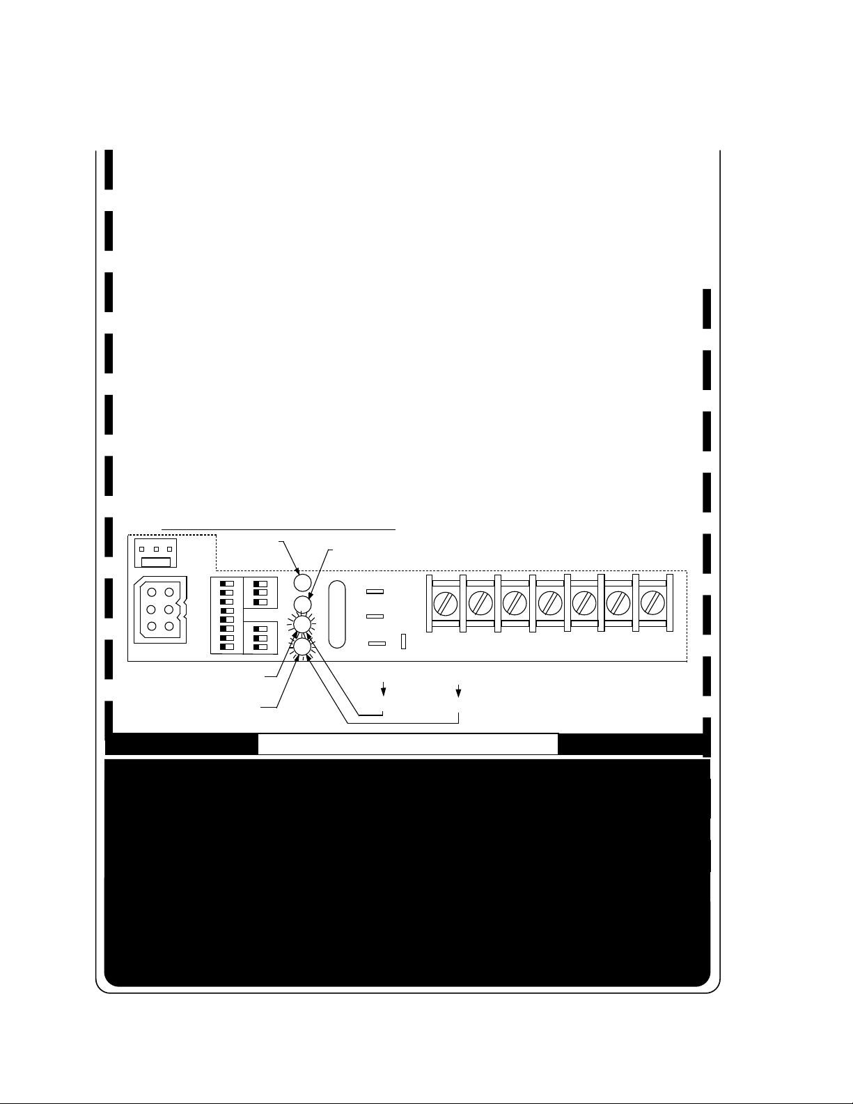
SEC-2
SEC-1
W/W1 Y/Y2 HUMRG
24V
W2 Com
DEHUM
SEC-2
SEC-1
DE
DEHUM
W/W1 Y/Y2 HUMRG
24V
W2 Com
DE CONNECTION
WITHOUT DE
CONNECTION
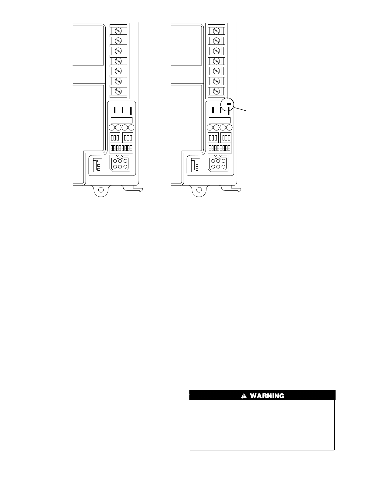
Fig. 1—Variable Speed Furnace Control
b. R-W/W1 with R-Y/Y2 and R-G signals terminated—
The blower continues to operate completing a normal
blower off delay.
11. Post purge—The inducer continues operating for 15 sec after
gas valve is de-energized.
Step 7—Continuous Fan Mode
1. Operating with continuous fan only.
a. Call for continuous fan—The thermostat closes R-G
circuit.
b. Blower on—The blower starts immediately.
NOTE: The blower starts at approximately 400-500 RPM. After
20 sec, the motor is turned offfor 1/10 of a sec where a coast down
calibration is done to evaluate resistance of the conditioned air
duct system. The microprocessor then determines blower RPM
required to provide proper airflow for heating mode.
NOTE: The continuous fan speed is the same as low-heat speed
unless it is field adjusted to another desired airflow. See Continuous Fan Setup Switches section in Installation, Start-Up, and
Operating Instructions for details. There is also a chart on
schematic diagram shown in Appendix A.
c. Electronic Air Cleaner—The EAC-1 terminal is ener-
gized whenever blower operates, regardless of operating
mode.
2. Operating with continuous fan (R-G) and call for heat
(R-W/W1) is received—Same as heat pump mode except
blower on delay is 10 sec less than the heat mode. After call
for heat (R-W/W1) is terminated, the blower remains operating at low-heat speed for selected blower off delay before
resuming continuous fan speed.
3. Operating with continuous fan (R-G) and call for cooling
(R-Y/Y2) is received—See Cooling Mode section. After call
WITH DE
CONNECTION
A98293
for cooling (R-Y/Y2) is terminated, the blower remains
operating at cooling speed for 90 sec before resuming continuous fan speed.
Step 8—Component Test
All components are functionally operated except gas valve with
component test feature.
This feature helps diagnose a system problem in case of a
component failure.
NOTE: Setup switch SW-1 MUST be in OFF position or Fault
Code 22 (setup error) will occur.
NOTE: NO thermostat signal may be present at control center,
and all blower time delay off periods must be completed.
To initiate component test feature, proceed with the following:
1. Leave 115-v power to furnace turned on.
2. Remove main furnace door.
3. Remove blower access panel.
4. Turn setup switch SW-6 to ON position.
5. Manually close blower access panel door switch.
On some models, blower access paneldoor switch opens only
24-v power to control center. No component operation can
occur. The 115-v power is still present at control center,
transformer, inducer motor, and main blower motor. Caution
must be taken when manually closing this switch for service
purposes. Failure to follow this warning could result in
personal injury or death.
4
Page 5
When items 1-5 have been completed, the following will occur:
1. The control center goes through a brief self test. This self test
takes approximately 2 sec to complete. After door switch is
closed, red (microprocessor) LED briefly comes on. Then
green LED comes on for 1 sec, followed by 1 sec where both
green and yellow LEDs are on. During this time, the microprocessor is checking itself.
2. Inducer motor operates for 20 sec at low speed, operates 20
sec at high speed, then turns off.
3. Hot surface ignitor is energized for 15 sec, then de-energized.
4. Main blower motor operates for 20 sec at low speed, operates
for 20 sec at high speed, then turns off.
5. After component operation test is completed, 1 or more fault
codes (11, 22, 41, or 42) will flash. See service label on back
of main furnace door or Fig. 1 for explanation of fault codes.
NOTE: To repeat component test, turn setup switch SW-6to OFF
and then back to ON.
After component test, perform the following:
1. Release blowerpanel access door switch and turn setup switch
SW-6 to OFF position.
2. If applicable, replace blower access panel and check LED
status by removing plug in blower access panel.
3. Reinstall main furnace door if all LEDs are off, indicating
furnace is ready to operate when a signal from thermostat is
received.
Step 9—Bypass Humidifier Mode
When setup switch SW-3 BPH is in ON position, RPM calculated
for low heat is multiplied by 1.15 for all furnace model sizes. This
compensates for increased return-air temperature caused by bypassed air supply.
standard humidistat to do dehumidification since the contacts open
on high humidity, thus removing the 24-v signal to initiate
dehumidification.
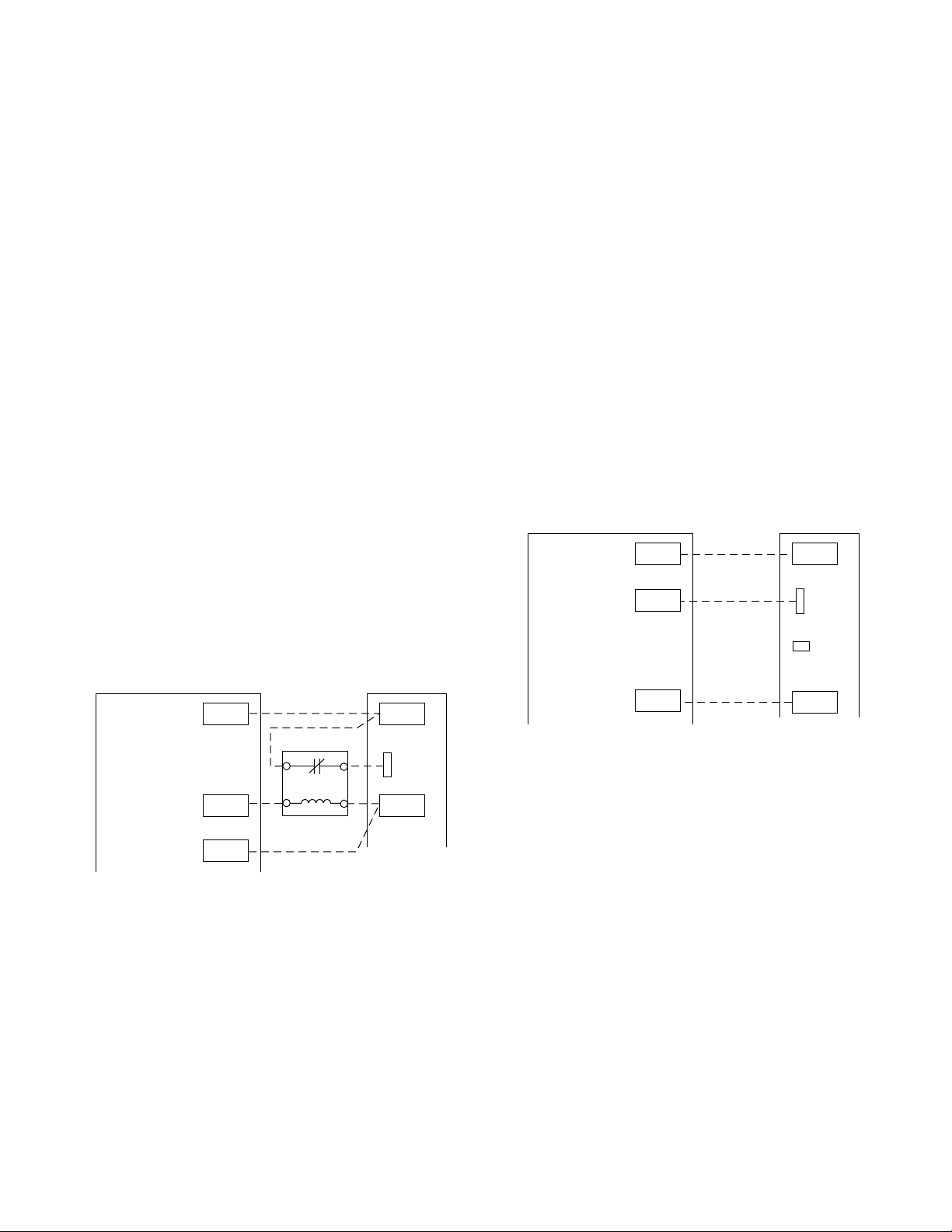
On the older style variable speed furnace controls, a field supplied
relay is required betweenthe thermidistator humidistatcontrol and
furnace. The relay coil is connected between DHUM output on the
thermidistat control and C
humidistat output and C
OM terminal on the furnace control or the
OM terminal on the furnace control. Its
normally closed contact is connected between R and DEHUM
terminals on the furnace control. (See Fig. 1 and Fig. 2). When a
dehumidify demand exists, relay is de-energized, and normally
closed contacts supply 24-v to the furnace DEHUM terminal. As
a result, the furnace control reduces the blower airflow by 15
percent to 340 CFM per ton during continuous fan or cooling
operation.
On newer style variable speed furnace controls, a field supplied
relay IS NOT required. The DEHUM output on the thermidistat
control or the humidistat output is connected directly to the
DEHUM terminal on the furnace control. In addition, the DE
jumper located next to the DEHUM terminal must be removed to
enable the DEHUM input. (See Fig. 1 and Fig. 3). When a
dehumidify demand exists, the furnace control reduces the blower
airflow by 21 percent to 315 CFM per ton during continuous fan
or cooling operation.
VARIABLE-SPEED
THERMIDISTAT
24 VAC HOT
DEHUMIDIFY
RR
DHUM
CONDENSING
FURNACE
DEHUM
VARIABLE-SPEED
THERMIDISTAT
24 VAC HOT
DEHUMIDIFY
24 VAC COMM
Fig.2—Without DE Connection
RR
DHUM
C
CONDENSING
FURNACE
DEHUM
Com
A98294
Step 10—Dehumidification Mode
A dehumidification input is provided via a 1/4-in. male quickconnect terminal labeled DEHUM, located next to the transformer
secondary connections. The DEHUM input acts differently depending on which style of variable speedfurnace control you have.
The older style variable speed furnace control (shown in Fig. 1)
DOES NOT have a DE connection while the newer style variable
speed furnace control (shown in Fig. 1) has a DE connection. The
newer style variable speed furnace control is expected to be
available by mid 1998. Both of these variable speed furnace
controls function the same except the DEHUM logic is reversed.
This logic reversal has come about from historical use of a
DE
NOTE 1
24 VA C COMM
Fig. 3—With DE Connection
C
NOTE 1 - Remove DE Connection
To Enable DEHUM Input
Com
A98295
This blower speed reduction compensates for high humidity
conditions during cooling operation on all furnace model sizes.
Reference Thermidistat™ Control Installation, Start-up, and Operating Instructions for further details.
Step 11—Zone Mode
When setup switch SW-5 MZ is in ON position, blower motor
control is the same as above except with the following exceptions:
1. While bloweris operatingin either low heat or continuous fan,
the coast down calibration is performed once a minute to
update blower RPM for zone damper position changes during
a given cycle.
NOTE: Boards with date codes of 9506 or later will not perform
a coast down calibration if blower pulse width to blower motor is
greater than 60 percent. This prevents nuisance faults from
occurring when a high continuous fan CFM has been selected.
2. While blower is operating in either high heat or cooling,
blower pulse width to blower motor is frozen when blower
RPM is within 10 percent of calculated blower RPM for 5 sec.
5
Page 6

START HERE—If a problem exists, the service technician should always begin troubleshooting here.
STEP ACTION YES NO GO TO
Remove furnace door first. DO NOT REMOVE BLOWER ACCESS PANEL! Record status of LED’s
1.
1-4. See Service Label/Fault Code Instructions (Fig.4).
2. Are any LEDs flashing? 53 —
3. Are any LEDs on solid? (Solid means ON continuously.) 4 8 —
4. Go to page number indicated in Index for LEDs 1, 2, 3, or 4 ON SOLID. — — INDEX
5. Is RED LED2 flashing? 67 —
6. Go to page number indicated in Index for RED LED2 FLASHING. — — INDEX
7. Go to page number indicated in Index for subsection covering fault code being flashed. — — INDEX
8. Is power on? (DO NOT cycle power to unit). 10 9 —
9. Turn power on. —— 20
10.
11. Does problem appear to be low cooling airflow? 12 13 —
12. Go to page number indicated in Index for subsection covering NOT ENOUGH COOLING AIRFLOW. — — INDEX
13. Make sure thermostat is calling for heat. — — 14
14. Make sure thermostat fan control is in AUTO position if equipped. — — 15
15. Observe operation of furnace for 20 minutes or until fault occurs. — — 16
16. Does a fault occur? 717 —
17. Is temperature rise below range specified on rating plate when unit is running in high fire? 18 19 —
18.
19. Does furnace operate properly? 31 28 —
20.
21. Disconnect R thermostat lead, then wait until blower motor stops. — — 22
22. Are any LEDs flashing? 24 23 —
23. Are any LEDs on solid? (Solid means ON continuously.) 4 25 —
24. Is RED LED2 flashing? 67 —
25. Put setup switch SW-1 in ON position. — — 26
26.
27. Are LEDs 3 and 4 flashing a Fault Code 11? 29 30 —
28.
29. Go to page number indicated in Index for CLEANUP AND START-UP INSTRUCTIONS. — — INDEX
30. Go to page number indicated in Index for subsection covering first fault code flashed. — — INDEX
31. Disconnect the R thermostat lead, then wait until blower motor stops. — — 32
32. Put setup switch SW-1 in ON position. — — 33
33.
34. Are LEDs 3 and 4 flashing a Fault Code 11? 35 30 —
35.
Remove blower access panel and depress door switch. Use a piece of tape to hold switch closed.
Wait a few sec for self test before proceeding to next step.
Go to page number indicated in Index for subsection
covering HIGH FIRE TEMPERATURE RISE TOO LOW (COLD BLOW).
Remove blower access panel and depress door switch. Use a piece of tape to hold switch closed.
Wait a few sec for self test before proceeding to next step.
Record fault codes listed in fault history.
NOTE: Read fault codes until they repeat. The last fault code that occurred will flash first followed by the lowest number fault code. (EXAMPLE: 13, 13, 44)
Go to page number indicated in Index for subsection covering NO OPERATION WITH NO FLASHING FAULT CODE.
Record fault codes listed in fault history.
NOTE: Read fault codes until they repeat. The last fault code that occurred will flash first followed by the lowest number fault code. (EXAMPLE: 13, 13, 44)
Go to page number indicated in Index for the CLEANUP AND START-UP INSTRUCTIONS. If this
problem persists on an intermittent basis, replace furnace control board. If problem still persists on
an intermittent basis after replacing furnace control board, contact your distributor.
—— 2
—— 11
— — INDEX
—— 21
—— 27
— — INDEX
—— 34
— — INDEX
6
Page 7
SERVICE
LED CODE
RED LED1 ON
RED LED2 ON
YELLOW LED3 ON
GREE N LE D 4 ON
RED LED2 FLAS HING
EACH OF THE FOLLOWING STATUS CODES IS A TWO DIGIT NUMBER WITH THE FIRST DIGIT
DETERMINED BY NUMBER OF FLASHES OF THE YELLOW LED AND THE SECOND DIGIT
DETERMINED BY NUMBER OF FLASHES OF THE GREEN LED.
11 NO FAULT IN RECENT HISTORY DISPLAY - Indicates no faults have occurred within last five cycles.
To rea d recent fault history put setup switch "SW-1" in th e "ON" position. To clear rec ent fault
history, put setup switch "SW-1" in the "ON" position and jumper thermostat terminals
"R", "W/W1", and "Y/Y2" sim ultaneously until an "11" is flashed.
12 BLOWER CALIBRATION LOCKOUT - Indi ca t es RPM calc ulated for low heat wa s less than 250 RPM
or greater than 1300 RPM on two successive attempts. Auto reset after three hours. Reset
power and refer to fault #44 section.
13 LIMIT SWITCH LOCKOUT - Indicates the occurrence of 10 successive limit trips during high heat
or three successive limit trips during low heat. Auto reset after three hours.
Check for: - Improper or misaligned limit and/or limit shield.
- Improper high or low heat gas input adjustment.
- Stuck high heat solenoid in gas valve.
14 IGNITION LOC KO UT - Control will auto-reset after three hours. Refer to #34.
21 INVALID MODEL SELECTION - Indicates model plug is missing or incorrect. See wiring diagram
for correct connector jumper location.
22 SETUP ERROR - Indicates setup switch "SW-1" or SW-6" is positioned improperly. The following
combinations will cause the fault.
- Th ermostat call with "SW-1" "ON" .
- Th ermostat call with "SW-6" "ON" .
-"SW-1" and "SW-6" both "ON" togeth er.
23 INVALID BLOWER AIRFLOW SELECTION - Indicates improper "A/C" or "CF" switch setting. The 042
and 14 units can deliver 1-1/2 to 3-1/2 tons A/C and 600 to 1400 CFM for continuous fan. The
060 and 20 unit can deliver 2 to 5 tons A/C and 800 to 2000 CFM for continuous fan. If code is
flashing unit will default to closest allowable airflow.
24 SECONDA RY VOLTAGE FUSE IS OPEN
Check for: - Short circuit in secondary voltage (24V) wiring.
31 HIGH PRESS URE SWITCH FAULT - Indicates high pressure switch is closed at call, or in low heat,
or fails to close after call, or opens in high heat.
Check for: - Plugged condensate drain.
- Water in vent piping, possibly sagging pipe.
- Improper pressure switch wiring or pressure switch tubing connections.
- Failed or "Out-of-Cali bration" pr essure switch es.
32 LOW PRESSUR E SWITCH FAULT - Indi cates low p ressure switc h is closed at call, or fails to close
after call, or opens during operation.
Check for: - Plugged condensate drain.
- Water in vent piping, possibly sagging pipe.
- Improper pressure switch wiring or pressure switch tubing connections.
- Failed or "Out-of-Cali bration" pr essure switch es.
33 LIMIT OR FLAME ROLL-OUT SWITCH IS OPEN - Indicates the limit, rollout switch or auxiliary limit
switch is open or the un it is operat ing in high heat only m ode due to t wo successive low he at
limit trips. Check for: - Imp r oper or misaligned limit and/o r limit shield.
- Impro per low heat gas input a djustment.
- Stuck h igh heat solenoid in gas valve.
Furnace is operating in emergency heat.
The microprocessor has malfunctioned. To reset: Put setup switch "
position and jumper thermostat terminals "
the door switch pushed in and power to the unit "
OFF
setup switch in the "
Furnace is operating in high heat.
Furnace is operating in low heat.
Line voltage polarity is reversed.
" position. If
STATUS
R
", "
LED2
reappea rs replace m ain control board.
SW-1
W/W1
", and "
Y/Y2
" simultaneously with
ON
". Disconnect jumper and place
" in the "ON"
A99243a
7
Page 8
34 IGNITION PROVING FAULT - Control will try three more times before a lockout #14 occurs.
Check fo r: - G as v a lve de fec ti ve o r g a s va lv e t urned "OFF ".
- Defective Hot Surface Ignitor - Manual valve shut-off.
- Low inlet gas pressure - Flame sensor must be ungrounded.
- Gre e n wire MU ST b e connected to furnace sheet meta l.
- Proper flame sense microamps (.5 microamps D.C. minimum, 4.0 - 6.0 nominal in HIGH HEAT)
- Inadequate flame carryover or rough ignition. - Control ground continuity
- Oxid e b u ildup on flame sensor (clean with f ine steel wool.)
41 BLOWER OUTSIDE VALID SPEED RANGE - Indicates the blower is not operating at the calculated
RPM. If this fault occurs in conjunction with fault #44 check wiring to motor otherwise refer to
the trouble-shooting guide.
42 INDU CER OU TSIDE VALID SPEED RANGE - Indicates the inducer is not operating at the
calculated RPM, or has not started within 10 seconds after a call for heat. Check wiring to
motor otherwise refer to the trouble-shooting gu ide.
43 PRESSURE SWITCH CALIBRATION FAULT- Indicates the low and high pressure switch "make"
points during high heat pur g e are not w ithin the ca libration range.
Check for: - Plugged condensate drain.
- Water in vent piping, possibly sagging pipe.
- Improper pressure switch wiring or pressure switch tubing connections.
- Failed or "Out of Calibration" pressure switches.
44 BL OWER CALI BRATIO N FAULT - Indicates the calculated blower speed is below 250 or above
1300 RPM. Unit will default to low o r high heat mode if possible. If this fault occurs in conjunction
with fault #41 check wiring to motor otherwise refer to the trouble-shooting guide. If this fault
occurs by it se lf che c k for und e rsize d duc twork, or exces siv e st a tic ca u s ed by a d ir ty fil te r , o r
closed registers.
STATUS CODE EXAMPLE
RED LED1
EMER HEAT
SETUP SW,(SW1-8)
OFF
1
23456
8
YELLOW LED3
HIGH HEAT
GREEN LED4
LOW HEAT
OFF
321
OFF
1
7
32
1
2
3
4
RED LED2
MICROPROCESSOR
MALFUNCTION
FUSE
DEHUM
COUN T TH E NO.
OF FLASHES
(4)
DE
C
W2
OM
24 V
COUNT THE NO.
OF FLASHES
=
(2)
42 FAULT
INDUCER OUTSIDE VALID
SPEED RANGE
GRY/Y2W/W1
COMPONENT TEST
To in itiate the component test sequence, shut "OFF" the room ther mostat o r d isconnect the "R"
thermostat lead. Put setup switch "SW-6" in the "ON" position to start the component test sequence.
Once initiated the main board will turn "ON" the inducer motor-low speed, inducer motor-high speed,
hot surface ignitor, blower motor-low speed, and blower motor-high speed for 15-20 seconds each.
When component test is completed one or more of the following codes will flash. Gas Valve and
Humidifier will not be turned on.
CODE DESCRIPTION
11
Indicates inducer and blower m oto r tes ted OK. Visual check of hot surface ignitor re quired.
22
SETUP ERROR
41
BLOWER OUTSIDE VALID SPEED RANGE -
- Sam e as code 22 above.
Indicates blower motor failed test. Check blower, wiring,
and control center.
42
INDUCER OUTSIDE VALID SPEED RANGE -
Indicates inducer motor failed test. Chec k inducer,
wiring and control center.
To repeat component test turn se tup switch "SW-6" "OFF" and then back "ON". After component test is
completed put setup switch "SW-6" in the "OFF" posit ion and reconnect the "R" thermostat lead.
320624-101 REV. J
→Fig. 4—Service Label/Fault Code Instructions
8
HUM
A99243
A99243b
Page 9
IMPROPER OPERATION WITH NO FLASHING FAULT CODE—Generally, this indicates there is no power to
furnace control board.
STEP ACTION YES NO GO TO
1. Make sure power is on. —— 2
Remove blower access panel and depress door switch. Use a piece of tape to hold switch closed.
2.
Wait a few sec for self test before proceeding to next step.
3. Make sure thermostat is calling for heat. — — 4
4. Make sure thermostat fan control is in AUTO position if equipped. — — 5
5. Check fuses, breakers, or manual disconnects to be sure they are correctly set. — — 6
6. Does 120-v wiring match unit wiring schematic? 9 7 —
7. Fix problem. —— 8
8. Go to page number indicated in Index for CLEANUP AND START-UP INSTRUCTIONS. — — INDEX
9. Do you have 120 vac at primary leads P1 and P2 on furnace control board? 14 10 —
10. Do you have 120 vac to furnace control board? 11 12 —
11. Check all 120-vac connections at furnace control board. If necessary, replace furnace control board. — — 8
12. Turn power off. —— 13
13. Check continuity of power supply leads and door switch if wired with 120 vac. — — 7
14. Do you have 24v between SEC-1 and SEC-2 on furnace control board? 19 15 —
15. Turn power off. —— 16
16. Do you have continuity across door switch? 17 18 —
17. Replace transformer. If transformer fails again, replace transformer and furnace control board. — — 8
18. Replace door switch. —— 8
19. Do you have 24v between R and Com on furnace control board? 21 20 —
20. Replace furnace control board. —— 8
21. Do you have 24v between W/W1 and Com on furnace control board? 24 22 —
22. Check to see that thermostat is calling for heat. — — 23
23. You have a defective thermostat or a break in the wiring between thermostat and furnace. — — 7
24. Does furnace respond to the call for heat? 27 25 —
25. Turn power off. —— 26
26.
27.
28. Disconnect BROWN wire to gas valve GV. — — 29
29.
30. Disconnect humidifier lead from HUM terminal on furnace control board. — — 31
31.
32. There is a direct short in wiring to humidifier solenoid coil, or short is inside humidifier solenoid coil. — — 7
33.
34.
35. Disconnect BROWN wire to gas valve GV. — — 36
36.
37. Replace gas valve. —— 8
38.
39. Disconnect humidifier lead from HUM terminal on furnace control board. — — 40
40.
Press down on microprocessor chip and make sure it is properly seated to furnace control board. If
it is, replace furnace control board.
Does furnace keep repeating the following cycle? Inducer motor MTR1 runs, inducer motor MTR1
stops, furnace control board goes through a self-test sequence, blower motor runs for 1 minute, and
then cycle repeats.
Does furnace still alternately cycle inducer motor, go through a self test, and then run blower motor
as described in Step 27?
Does furnace still alternately cycle inducer motor, go through a self test, and then run blower motor
as described in Step 27?
There is a direct short in either the pressure switch circuits, gas valve GV, or wiring to gas valve
GV. If hot surface ignitor comes on during the cycle, short is in gas valve or wiring to gas valve.
Does furnace ever abruptly shut down with no fault code, no inducer post purge, no blower off delay, and then restart heating cycle?
Does furnace still abruptly shut down with no fault code, no inducer post purge, no blower off delay,
and then restart heating cycle?
Go to page number indicated in Index for CLEANUP AND START-UP INSTRUCTIONS. If problem
persists on an intermittent basis, replace furnace control board. If problem still persists after replacing furnace control board, contact your distributor.
Does furnace still abruptly shut down with no fault code, no inducer post purge, no blower off delay,
and then restart heating cycle?
—— 3
—— 7
28 34 —
30 37 —
33 32 —
—— 7
35 38 —
39 37 —
— — INDEX
33 32 —
9
Page 10
NOT ENOUGH COOLING AIRFLOW—Generally, this indicates the Y/Y2 thermostat lead is not properly
connected.
STEP ACTION YES NO GO TO
Remove blower access panel and depress door switch. Use a piece of tape to hold switch closed.
1.
Wait a few sec for self test before proceeding to next step.
Make sure thermostat is calling for cooling. If thermostat lead G is not connected, jumper across
2.
thermostat terminals R and G.
3. Make sure thermostat fan control is in AUTO position if equipped. — — 4
4. Do you have 24v across Y/Y2 and Com on furnace control board? 8 5 —
You have a defective thermostat, or a break in wiring between thermostat and furnace, or the Y/Y2
5.
thermostat terminal is not wired to thermostat.
6. Fix problem. —— 7
7. Go to page number indicated in Index for CLEANUP AND START-UP INSTRUCTIONS. — — INDEX
Are air conditioning select switches A/C set to proper tonnage as required by condensing unit? (See
8.
Table 1.)
Set air conditioning select switches A/C for proper tonnage as required by condensing unit. (See
9.
Table 1.)
10. Disconnect the G thermostat lead or jumper if used. — — 11
11. Does blower motor turn off in 90 sec when G thermostat lead is disconnected? 12 13 —
12. Replace furnace control board. —— 7
13. Observe operation of furnace in cooling mode for 8 minutes. — — 14
14. Does furnace operate properly in cooling mode? 15 16 —
Make sure outdoor unit is properly charged. If it is, go to page number indicated in Index for
15.
16. Does furnace abruptly go through a self-test sequence as blower comes up to speed? 17 24 —
17. Do you have less than 17 vac between R and Com on furnace control board? 18 24 —
18. Do you have less than 90 vac between P1 and P2 on furnace control board? 19 20 —
19.
20. Disconnect the R thermostat lead. —— 21
21. Do you have less than 17 vac between R and Com on furnace control board? 22 23 —
22. Replace transformer. —— 7
23.
24.
CLEANUP AND START-UP INSTRUCTIONS. If problem persists on an intermittent basis, replace
furnace control board. If problem still persists after replacing furnace control board, contact your distributor.
Make sure the wire gage between main fuse box and furnace complies with wire size specification
in Installation, Start-Up, and Operating Instructions.
Check the thermostat wire gage between furnace and thermostat, and furnace and outdoor unit. It is
recommended that AWG No. 18 color-coded copper thermostat wire be used for lengths up to 100
ft. For wire lengths over 100 ft, use AWG No. 16 wire.
Press down on microprocessor chip and make sure it is properly seated to furnace control board. If
it is, replace furnace control board.
—— 2
—— 3
—— 6
10 9 —
—— 7
— — INDEX
—— 6
—— 6
—— 6
AIR CONDITIONER
(TONS)
Default
1-1/2 600 ON OFF OFF X X X — — —
2 800OFFONOFFXXXXXX
2-1/2 1000 ON ON OFF XXXXXX
3 1200 OFF OFF ON XXXXXX
3-1/2 1400 ON OFF ON XXXXXX
4 1600 OFF ON ON — — — X X X
5 2000 ON ON ON — — — X X X
X—Indicates allowable selection.
AIRFLOW
(CFM)
1200 or
Table 1—Air Conditioning (A/C) Airflow Setup Switch Position
A/C SWITCH POSITION ALLOWABLE FURNACE MODEL SETUP
A/C-1 A/C-2 A/C-3 040 060 080 080 100 120
2000
OFF OFF OFF
3 Tons
1200 CFM
3 Tons
1200 CFM
3 Tons
1200 CFM
5 Tons
2000 CFM
5 Tons
2000 CFM
5 Tons
2000 CFM
10
Page 11
HIGH-FIRE TEMPERATURE TOO LOW—Generally, this indicates the HIGH/LOW solenoid in gas valve GV has
failed or furnace is extremely underfired.
STEP ACTION YES NO GO TO
1. Turn power off and remove blower access panel. Make sure thermostat is NOT calling for heat. — — 2
Depress door switch. Use a piece of tape to hold switch closed. Wait a few sec for self test before
2.
proceeding to next step.
3. Set thermostat to call for heat or jumper R and W/W1 thermostat terminals. — — 4
When GREEN LED4 is ON solid, clock low-fire gas rate. You have 16 minutes on this first call for
4.
heat. On propane installations, check manifold pressure.
When YELLOW LED3 is ON solid, clock high-fire gas rate. On propane installations, check manifold
5.
pressure.
6. Is high-fire rate approximately same as low-fire rate? 7 11 —
Do you have 24 vac across gas valve terminal HI and Com on furnace control board during high
7.
fire?
You have an open wire or bad terminal on BROWN wire from furnace control board to gas valve
8.
GV. Repair it or replace the harness.
9. Go to page number indicated in Index for CLEANUP AND START-UP INSTRUCTIONS. — — INDEX
10. Replace gas valve. —— 9
11. Is high-fire rate within 2% of that specified on rating plate? 13 12 —
12.
13. Check outdoor condensing unit for operation during heating cycle. — — 14
14.
15. Check return-air ducts in unheated spaces for leaks. — — 9
Ensure gas inlet pressure and burner orifices are correct, then adjust gas valve to proper rate. If it
cannot be adjusted to proper rate, replace gas valve.
Check temperature rise with blower door in place. Temperature rise should be mid-range or slightly
higher than midpoint of range stated on furnace rating plate. If return temperature is below 60°F,
condensation may form on heat exchangers. If left uncorrected, failure will result.
—— 3
—— 5
—— 6
10 8 —
—— 9
—— 9
—— 15
LEDs 1, 2, 3, or 4 ON SOLID (SOLID means on continuously.)
• RED LED1 ON SOLID indicates furnace is operating in emergency heat.
• RED LED2 ON SOLID indicates microprocessor has malfunctioned or secondary voltage to furnace control board is low.
• YELLOW LED3 ON SOLID indicates furnace is operating in high fire.
• GREEN LED4 ON SOLID indicates furnace is operating in low fire.
STEP ACTION YES NO GO TO
1. Turn power off and remove blower access panel. — — 2
2. Turn power on and depress door switch. Use a piece of tape to hold switch closed. — — 3
3. Jumper R and W/W1 thermostat terminals on furnace control board. — — 4
4. Is RED LED1 ON? 59 —
5. Is setup switch SW-4 labeled EMER. HEAT in ON position? 6 7 —
6. Put setup switch SW-4 labeled EMER. HEAT in OFF position. — — 8
7. Replace furnace control board. —— 8
8. Go to page number indicated in Index for CLEANUP AND START-UP INSTRUCTIONS. — — INDEX
9. Disconnect jumper wire across R and W/W1 thermostat terminals. — — 10
10. Is RED LED2 ON? 11 32 —
11. Do you have less than 17 vac between R and Com on furnace control board? 12 19 —
12. Do you have less than 90 vac between P1 and P2 on furnace control board? 13 15 —
13.
14. Fix problem. —— 8
15. Disconnect R thermostat lead. —— 16
16. Is RED LED2 ON? 17 18 —
17. Replace transformer. —— 8
18.
19. Disconnect all thermostat leads from furnace control board. — — 20
20. Put setup switch SW-1 in ON position and jumper R, W/W1, and Y/Y2 thermostat terminals. — — 21
21. Does RED LED2 turn OFF? 22 7 —
22. Put setup switch SW-1 back in OFF position. — — 23
23. Turn power off and reconnect thermostat leads to furnace control board. — — 24
24. Turn power on. —— 25
25. Does RED LED2 turn back ON? 26 36 —
26. Disconnect all thermostat leads from thermostat control board. — — 27
27.
Make sure wire gage between main fuse box and furnace complies with wire size specification in
Installation, Start-Up, and Operating Instructions.
Check thermostat wire gage between furnace and thermostat, and furnace and outdoor unit. It is
recommended that AWG No. 18 color-coded copper thermostat wire be used for lengths up to 100
ft. For wire lengths over 100 ft, use AWG No. 16 wire.
Put setup switch SW-1 in ON position and jumper R, W/W1, and Y/Y2 thermostat terminals simultaneously until RED LED2 turns OFF.
—— 14
—— 14
—— 28
11
Page 12
28. Put setup switch SW-1 back in OFF position. — — 29
29. Jumper R and W/W1 thermostat terminals. — — 30
30. Does RED LED2 turn back ON? 731 —
31. Install isolation relays in the W/W1 and Y/Y2 circuits per Fig. 5 in Appendix B or replace thermostat. — — 8
32. Was RED LED2 ON before you started Step 1? 34 33 —
33.
34.
35.
36.
37.
38. Replace gas valve. —— 8
39. Isolate humidifier with a separate 24-vac supply or replace humidifier solenoid coil. — — 14
40. Observe operation of furnace through a 4 minute cooling cycle. Does RED LED2 turn ON? 41 47 —
41. Disconnect all thermostat leads from furnace control board. — — 42
42.
43. Put setup switch SW-1 back in OFF position. — — 44
44. Reconnect only outdoor unit to Y/Y2 and Com terminals on furnace control board. — — 45
45. Jumper R and Y/Y2 thermostat terminals. — — 46
46. Does RED LED2 turn back ON? 34 31 —
47.
Solid YELLOW LED3 indicates furnace is in high fire and solid GREEN LED4 indicates furnace is in
low fire.
Check outdoor unit contactor. Failure to pull in can cause excessive current draw on low-voltage
circuit. This can be intermittent and may require extended operation to repeat problem. Isolating
outdoor unit may solve problem. (See Fig. 6 in Appendix B.)
Check thermostat wire gage between furnace and outdoor unit. It is recommended that AWG No.
18 color-coded copper thermostat wire be used for lengths up to 100 ft. For wire lengths over 100
ft, use AWG No. 16 wire.
Observe operation of furnace through a 20 minute heat cycle. Try to pinpoint where in cycle RED
LED2 turns ON.
Go to step indicated below if RED LED2 turns ON when 1 of the following events occur: — — —
• When gas valve is energized. —— 38
• When HSI is energized. —— 39
• When high-pressure switch HPS makes during transition from low to high fire. — — 38
• RED LED2 never turns ON. —— 40
Put setup switch SW-1 in ON position and jumper R, W/W1, and Y/Y2 thermostat terminals simultaneously until RED LED2 turns OFF.
Go to page number indicated in Index for CLEANUP AND START-UP INSTRUCTIONS. If problem
persists on an intermittent basis, replace furnace control board. If problem still persists on an intermittent basis after replacing furnace control board, contact your distributor.
—— 8
—— 35
—— 14
—— 37
—— 43
— — INDEX
RED LED2 FLASHING—Indicates line voltage polarity is reversed.
STEP ACTION YES NO GO TO
Turn power off, remove blower access panel, and disconnect all thermostat leads from furnace con-
1.
trol board.
2. Turn power on and depress door switch. Use a piece of tape to hold switch closed. — — 3
3. Is RED LED2 flashing? 64 —
4. Replace furnace control board, date code 9405 or later. — — 5
5. Go to page number indicated in Index for CLEANUP AND START-UP INSTRUCTIONS. — — INDEX
6. Do you have 120 vac across L2 and chassis ground? 7 8 —
7. Line voltage polarity is reversed. Fix problem. — — 5
8. Replace furnace control board. —— 5
—— 2
12
Page 13
Fault Code 11
NO FAULT IN RECENT HISTORY DISPLAY—This indicates 1 of the following:
• No faults have occurred in the last 5 previous cycles and setup switch SW-1 is in ON position.
• The fault history can be cleared by jumpering R, W/W1, and Y/Y2 thermostat leads simultaneously while setup switch SW-1 is in ON
position.
• Component test was successfully completed and setup switch SW-6 is in ON position.
STEP ACTION YES NO GO TO
1. Remove blower access panel and depress door switch. Use a piece of tape to hold switch closed. — — 2
2. Is setup switch SW-1 in ON position? 3 5 —
3. Put setup switch SW-1 in OFF position. — — 4
4. Go to page number indicated in Index for CLEANUP AND START-UP INSTRUCTIONS. — — INDEX
5. Is setup switch SW-6 in ON position. 6 7 —
6. Put setup switch SW-6 in OFF position. — — 4
Jiggle setup switches SW-1 and SW-6 back and forth. If Fault Code 11 continues to flash, replace
7.
furnace control board.
—— 4
Fault Code 12
BLOWER CALIBRATION LOCKOUT—This fault indicates that blower motor speed calculated for low heat is
either less than 250 RPM or greater than 1300 RPM on 2 successive attempts at calibration. Control will
auto-reset in 3 hours.
STEP ACTION YES NO GO TO
Turn power off, wait 30 sec, and then restore power. Reset thermostat. Observe operation of fur-
1.
nace through 1 heating cycle.
NOTE: Blower access panel must be in place.
2. Does only Fault Code 44 flash? 40 6 —
The problem is excessive restriction in the air delivery system. Check filters and ductwork. Use Ap-
3.
pendix E to evaluate.
4. Fix problem. —— 5
5. Go to page number indicated in Index for CLEANUP AND START-UP INSTRUCTIONS. — — INDEX
6. Does Fault Code 44 flash twice followed by Fault Code 41? 9 7 —
7. Does a different fault occur? 839 —
8. Go to page number indicated in Index for fault code flashed. — — INDEX
9. Turn power off and remove blower access panel. — — 10
10. Are all pins and wire leads intact on connectors between furnace control board and blower motor. 11 4 —
11.
12.
13. Does blower motor turn on and come up to speed (400-500 RPM) before fault code flashes? — 20 —
14.
15.
16. Replace furnace control board. —— 5
17.
→18.
Depress door switch. Use a piece of tape to hold switch closed. Wait a few sec for self test before
proceeding to next step.
Disconnect all thermostat leads from furnace control board and jumper R and W/W1 thermostat terminals.
Disconnect jumper wire across R and W/W1 thermostat terminals, turn power off, and then restore
power. Wait a few sec for self test before proceeding to next step.
Check RPM feedback line. To do this, connect a DC voltmeter across terminals PL3-2 ORANGE (+)
and PL3-3 VIOLET (–), then put setup switch SW-6 for COMPONENT TEST in ON position. Does
voltage across ORANGE and VIOLET wires change between states as shown below?
• State 1—OFF (12.0—12.5 vdc)
• State 2—LOW (10.7—11.7 vdc)
• State 3—HIGH(9.7—10.7 vdc)
Connect a DC voltmeter across ORANGE (+) and VIOLET (-) wires at connector PL13, then repeat
the COMPONENT TEST by turning setup switch SW-6 OFF and then back ON. Do you see approximately the same DC voltages across ORANGE and VIOLET wires that you saw in Step 15?
Replace entire blower motor or blower control module attached to the blower motor. If you replace
the blower control module go to step 44. Always inspect failed motor for water damage. If present,
find source of water and fix. Check A-coil and/or humidifier.
—— 2
—— 4
—— 12
—— 13
—— 15
16 17 —
18 19 —
—— 4
13
Page 14
19.
20. Remove tape from door switch and turn power off at main disconnect. — — 21
21. Does blower wheel rub against blower housing? 4 22 —
22. Does blower wheel turn freely?
23. Is blower wheel firmly mounted on motor shaft? 25 4 —
→24.
25. Disconnect jumper wire across R and W/W1 thermostat terminals. — — 26
26.
27. Do you have 120v between B1 and B2 on furnace control board? 28 4 —
28. Do you have 120v between BLACK and WHITE power leads at blower motor MTR2? 30 29 —
29.
30.
31.
32.
33.
34. Put setup switch SW-6 for COMPONENT TEST in OFF position. — — 35
35.
36.
37.
38.
39.
40.
41.
42. Jumper R and G thermostat terminals. Observe operation of furnace for next 30 sec. — — 43
43.
You have an open wire or bad terminal on either the ORANGE or VIOLET wire between connectors
PL13 and PL3. Repair it or replace blower harness(es).
Replace entire blower motor or blower control module attached to the blower motor. If you replace
the blower control module go to step 44. Always inspect failed motor for water damage. If present,
find source of water and fix. Check A-coil and/or humidifier.
Turn power back on. Depress door switch. Use a piece of tape to hold switch closed. Wait a few
sec for self test before proceeding to next step.
You have an open wire or bad terminal on either the BLACK or WHITE wire between furnace control board and blower motor MTR2.
Check blower ON/OFF line. To do this, connect a DC voltmeter across terminals PL3-1 RED (+)
and PL3-5 BLUE (-), then put setup switch SW-6 for COMPONENT TEST in ON position. Does
voltage across RED and BLUE wires change between states as shown below?
• State 1—OFF (-0.1 — 0.1 vdc)
• State 2—ON (9.0 — 10.0 vdc)
Disconnect PL3 from furnace control board and connect a DC voltmeter across terminals PL3-1 (+)
and PL3-5 (-) on furnace control board, then repeat COMPONENT TEST by turning setup switch
SW-6 OFF and then back ON. Does voltage across PL3-1 and PL3-5 change between states as
shown below?
• State 1—OFF (-0.1 — 0.1 vdc)
• State 2—ON (11.0 — 12.0 vdc)
Connect a DC voltmeter across RED (+) and BLUE (-) wires at connector PL13 then repeat COMPONENT TEST by turning setup switch SW-6 OFF and then back ON. Do you see approximately
the same DC voltages across RED and BLUE wires that you saw in Step 30?
You have an open wire or bad terminal on either the RED or BLUE wire between connectors PL13
and PL3. Repair it or replace blower harness(es).
Check blower PW line. To do this, connect a DC voltmeter across terminals PL3-1 RED (+) and
PL3-4 YELLOW (-), then put setup switch SW-6 for COMPONENT TEST in ON position. Does voltage across the RED and YELLOW wires change between states as shown below?
• State 1—OFF (-0.1 — 0.1 vdc)
• State 2—LOW (2.5 — 3.0 vdc)
• State 3—HIGH (7.0 — 7.5 vdc)
Disconnect PL3 from furnace control board and connect a DC voltmeter across terminals PL3-1 (+)
and PL3-4 (-) on furnace control board then repeat COMPONENT TEST by turning setup switch
SW-6 OFF and then back ON. Does voltage across PL3-1 and PL3-4 change as shown below?
• State 1—OFF (-0.1 — 0.1 vdc)
• State 2—LOW (3.0 — 4.0 vdc)
• State 3—HIGH (9.0 — 10.0 vdc)
Connect a DC voltmeter across RED (+) and YELLOW (-) wires at connector PL13 then repeat
COMPONENT TEST by turning setup switch SW-6 OFF and then back ON. Do you see approximately the same DC voltages across RED and YELLOW wires that you saw in Step 35?
You have an open wire or bad terminal on either the RED or YELLOW wire between connectors
PL13 and PL3. Repair it or replace blower harness(es).
Go to page number indicated in Index for CLEANUP AND START-UP INSTRUCTIONS. If problem
persists on an intermittent basis, replace blower motor. If problem still persists on an intermittent
basis after replacing blower motor, contact your distributor.
Turn power off and remove blower access panel. Depress door switch. Use a piece of tape to hold
switch closed. Wait a few sec for self test before proceeding to next step.
Disconnect all thermostat leads from furnace control board. If blower motor is running, wait until it
stops.
Approximately 20 sec after energizing G thermostat terminal, does blower motor pause briefly (less
than1/2 sec?)
Note:You can verify this pause using a clamp-on ammeter on BLACK power lead to blower
motor MTR2.
—— 5
—— 4
—— 27
—— 5
32 31 —
18 16 —
34 33 —
—— 5
37 36 —
18 16 —
18 38 —
—— 5
— — INDEX
—— 41
—— 42
318 —
14
Page 15
Wait at least 5 minutes after disconnecting line voltage from
equipment before opening blower motor to prevent electric
shock which can cause personal injury or death.
→44. Remove tape from door switch and turn power off at main disconnect. ——45
→45. Disconnect PL10 from blower assembly. — — 46
→46. Remove control box assembly from blower shelf and position out of the way. — — 47
→47. Remove blower assembly from furnace. — — 48
→48.
→49.
→50.
→51.
→52. Did the motor pass the resistance check? 53 55 —
→53. Does blower wheel turn freely with blower control module removed? 54 55 —
→54.
→55.
Disconnect both multi-pin connectors from blower control module attached to the blower motor. Be
sure to depress release latches on connectors or they may get damaged.
Remove two 1/4-in. hex head bolts from blower control module attached to blower motor. DO NOT
REMOVE TORX HEAD SCREWS located next to 1/4-in. hex head bolts.
Carefully lift blower control module off blower motor. Depress latch on internal connector to disconnect blower control module from motor portion of blower motor. DO NOT PULL ON WIRES. GRIP
PLUG ONLY.
When blower control module is completely detached from blower motor, verify with standard ohmmeter that the resistance from each motor lead in motor plug to unpainted motor end plate is
greater than 100k ohms. Then verify motor windings are not shorted or open by measuring resistance between each combination of pins in motor plug (there are three different combinations, pin
1-2, pin 2-3, and pin 1-3). Resistance should be approximately equal across each combination of
pins.
Replace blower control module. Inspect failed blower control module for water damage. If present,
find source of water and fix. Check A-coil and/or humidifier.
Replace entire blower motor including blower control module. Inspect blower control module for water damage. If present, find source of water and fix. Check A-coil and/or humidifier.
——49
——50
——51
——52
—— 5
—— 5
Fault Code 13
LIMIT SWITCH LOCKOUT—This fault indicates the limit switch has tripped 10 times in a row in high fire or 3
times in a row in low fire during a call for heat. Control will auto-reset in 3 hr.
NOTE: After 2 low-fire limit trips, the control is locked into high-heat mode; however, a third low-heat cycle can be forced due to excessive
restriction in air delivery system.
NOTE: Boards with date codes of 9506 or later will lock into high-heat mode after 2 low-fire limit trips and CANNOT be forced into a third
low-heat cycle. Therefore, units with these boards can only lock out if the limit switch trips 10 times in a row in high fire during a call for heat.
STEP ACTION YES NO GO TO
Turn power off and remove blower access panel. Disconnect all thermostat leads from furnace con-
1.
trol board.
2. Depress door switch. Use a piece of tape to hold switch closed. — — —
3. Put setup switch SW-1 in ON position. — — 4
Is a Fault Code 44 present in the fault history.
4.
NOTE: Read fault codes until they repeat. The last fault code that occurred will flash first followed by the lowest number fault code. (EXAMPLE: 13, 13, 44)
5. Put setup switch SW-1 in OFF position. — — 42
Does furnace have proper limit switch, limit shield, blower baffle (if used), and rear air baffle (if
6.
used)? If so are limit switch, limit shield, and heat exchangers properly aligned?
7. Replace limit switch. —— 9
8. Replace furnace control board. —— 9
9. Go to page number indicated in Index for CLEANUP AND START-UP INSTRUCTIONS. — — INDEX
10. Put setup switch SW-2 in ON position. — — 11
11. Jumper R and W/W1 thermostat terminals on furnace control board. — — 12
12.
13.
14.
15. Replace or rewire personality connector. — — 9
Is furnace considerably overfired (10% or more)? Clock input rate. Do not use manifold pressure
method unless using propane.
Ensure gas inlet pressure and burner orifices (natural or propane) are correct. Then adjust gas
valve to proper rate per Installation, Start-Up, and Operating Instructions. If it cannot be adjusted to
proper rate, replace gas valve.
Is the personality connector PL5 properly wired per furnace model sizing chart in upper left-hand
corner of wiring schematic?
—— 2
46 5 —
10 48 —
13 14 —
—— 9
50 15 —
15
Page 16

16. Does the installation have a bypass humidifier? 17 30 —
17. Is setup switch SW-3 in ON position? 19 18 —
18. Put setup switch SW-3 in ON position. — — 9
19.
20. Disconnect jumper wire across R and W/W1 thermostat terminals and wait until blower stops. — — 21
21. Remove blower access panel and put setup switch SW-3 in OFF position. — — 22
22.
23. Is the temperature rise in Step 22 more than 10°F higher than the temperature rise in Step 19? 24 8 —
24. Disconnect jumper wire across R and W/W1 thermostat terminals and wait until blower stops. — — 25
25. Remove blower access panel and put setup switch SW-3 in ON position. — — 26
26.
27. Is temperature rise from bypass greater than 15°F? 28 29 —
28. The bypass is oversized. Adjust damper or replace with properly sized bypass. — — 9
29. Disconnect jumper wire across R and W/W1 thermostat terminals and wait until blower stops. — — 30
30. Does the installation have modulating zone dampers? 31 51 —
31. Is setup switch SW-5 in ON position? 33 32 —
32. Put setup switch SW-5 in ON position? — — 9
33. Jumper R and W/W1 thermostat terminals on furnace control board. — — 34
34.
35.
36.
Cycle furnace with blower access panel in place and record temperature rise across furnace 6 minutes after main burner ignition.
Cycle furnace with blower access panel in place and record temperature rise across furnace 6 minutes after main burner ignition.
Cycle furnace with blower access panel in place and record the temperature rise across return air
duct before and after the bypass.
Does blower recalibrate every minute? Check by monitoring DC voltage across terminals PL3-1
RED (+) and PL3-5 BLUE (-). If DC voltage momentarily goes down to 0 vdc approximately every
60 sec after first blower calibration, then blower is recalibating properly.
Disable modulating zone damper system with all dampers in open position except bypass damper.
If the installation is equipped with a bypass damper, it should be in the closed position.
Put setup switch SW-2 in OFF position. Disconnect jumper wire across R and W/W1 thermostat terminals and reset the power. Reconnect jumper wire across R and W/W1 thermostat terminals and
monitor manifold gas pressure while observing furnace operation for 10 minutes.
—— 20
—— 23
—— 27
35 8 —
—— 36
—— 37
NOTE: Blower access panel must be in place.
37. Does a Fault Code 33 flash? 39 38 —
38.
39.
40. Replace gas valve. —— 9
41.
The problem is cause by the modulating zone damper system. Install a 2-stage thermostat and let
the zone system modulate gas flow. If you still have a problem, check the zone manufacturer’s installation and Troubleshooting Guide for corrective action.
While monitoring manifold pressure in Step 36, did it drop to low-fire manifold pressure during lowfire operation?
Replace blower motor and belly band.
NOTE: Torque belly band screw to 80 in.lb (6.7 ft. lb).
—— 9
49 40 —
—— 9
WARNING: DO NOT OVERTIGHTEN!
42. Jumper R, W/W1, and W2 thermostat terminals on furnace control board. — — 43
43.
44.
45. Disconnect jumper wire across R, W/W1, and W2 thermostat terminals and wait until blower stops. — — 6
46. Excessive restriction of airflow during locked in high-fire mode caused lockout. — — 47
47.
48. Fix problem. —— 9
49. Is temperature rise within ±10°F of midpoint of rise range? 51 41 —
50. Is temperature rise within ±10°F of midpoint of rise range? 51 16 —
51. Turn power off and install a temperature probe in front of limit switch button. — — 52
52.
53.
Is furnace considerably overfired (10% or more)? Clock input rate. Do not use manifold pressure
method unless using propane.
Ensure gas inlet pressure and burner orifices (natural or propane) are correct. Then adjust gas
valve to proper rate per the Installation, Start-Up, and Operating Instructions. If it cannot be adjusted to proper rate, replace gas valve.
Relieve restriction. Check all dampers, filters, and return-air grilles for blockage. Put setup switch
SW-1 in OFF position.
Turn power on and cycle unit. Does limit switch open at a temperature at least 10°F below temperature setpoint for limit switch. (EXAMPLE: The setpoint is 220°F, but switch opens at a temperature
below 210°F.)
The problem may be related ot poor air distribution. Add turning varies, more supply-air openings,
or more return-air openings. Use Appendix E to evaluate.
44 45 —
—— 9
—— 42
753 —
—— 48
16
Page 17

Fault Code 14
IGNITION LOCKOUT—This fault indicates the system failed to ignite gas and prove flame in 4 attempts.
Control will auto-reset in 3 hr. This fault could also indicate the gas valve relay GVR on furnace control board
is stuck closed or there is a miswire/short to gas valve wiring.
STEP ACTION YES NO GO TO
Turn power off and set thermostat to OFF position. Turn power back on and wait a few sec for self
1.
test before proceeding to next step.
2. Does Fault Code 14 flash? 36 —
3. There is a miswire or short to gas valve wiring. — — 4
4. Fix problem. —— 5
5. Go to page number indicated in Index for CLEANUP AND START-UP INSTRUCTIONS. — — INDEX
6. Does a different fault occur? 78 —
7. Go to page number indicated in Index for the fault code flashed. — — INDEX
8. Remove blower access panel and depress door switch. Use a piece of tape to hold switch closed. — — 9
9. Jumper R and W/W1 thermostat terminals. — — 10
10. Does Fault Code 14 start flashing when low-pressure switch LPS makes? 11 12 —
11. Replace furnace control board. —— 5
12. Does a different fault occur? 713 —
13. Disconnect jumper wire across R, and W/W1, 2 thermostat terminals and wait until blower stops.. — — 14
14. Jumper R, W/W1, and W2 thermostat terminals on furnace control board. — — 15
15. Does Fault Code 14 start flashing when high-pressure switch HPS makes? 16 17 —
16. The BLUE and GREEN wires to gas valve GV are reversed. — — 4
17. Disconnect jumper wire across R, W/W1, and W2 thermostat terminals and wait until inducer stops. — — 18
18. Put setup switch SW-1 in ON position. — — 19
19.
20. Cycle furnace several times to check for intermittent operation. — — 21
21.
22.
Is a Fault Code 34 present in fault history?
NOTE: Read fault codes until they repeat. The last fault code that occurred will flash first followed by the lowest number fault code. (EXAMPLE: 14, 14, 34)
Check that the GREEN wire is properly connected to furnace sheet metal and clean flame sensor
withfine sandpaper.
Go to page number indicated in Index for CLEANUP AND START-UP INSTRUCTIONS. If problem
persists on an intermittent basis, replace furnace control board. If problem still persists on an intermittent basis after replacing furnace control board, contact your distributor.
—— 2
20 22 —
—— 5
— — INDEX
Fault Code 21
INVALID MODEL SELECTION—Personality connector PL5 is either not connected or jumpered wrong.
STEP ACTION YES NO GO TO
1. Turn power off and remove blower access panel. — — 2
2. Is personality connector PL5 properly wired per furnace model size chart on wiring diagram? 5 3 —
3. Replace or rewire personality connector. — — 4
4. Go to page number indicated in Index for CLEANUP AND START-UP INSTRUCTIONS. — — INDEX
5. Depress door switch. Use a piece of tape to hold switch closed. — — 6
6. Make sure thermostat is calling for heat or jumper R and W/W1 thermostat terminals. — — 7
7. Will furnace operate while flashing fault code? 9 8 —
8. Replace furnace control board. —— 4
9. Are personality plug wires making good connection? 10 11 —
10.
11. Fix poor terminal connection or replace personality connector. — — 4
The furnace will operate acceptably; however, a model selection circuit failure has occurred and furnace control board is defaulting to last valid model selection. Board replacement is recommended
but not necessary. This fault code will flash continuously.
17
—— 4
Page 18

Fault Code 22
SETUP ERROR—This fault indicates that setup switches SW-1 or SW-6 are ON when they should be OFF. The
following combinations will cause the fault:
• Thermostat call with SW-1 ON.
• Thermostat call with SW-6 ON.
• SW-1 and SW-6 both ON together.
STEP ACTION YES NO GO TO
1. Turn power off and remove blower access panel. — — 2
Make sure thermostat is NOT calling for heating or cooling. Disconnect all thermostat terminal leads
2.
to make sure.
3. Is setup switch SW-1 in ON position? 4 6 —
4. Put setup switch SW-1 in OFF position. — — 5
5. Go to page number indicated in Index for CLEANUP AND START-UP INSTRUCTIONS. — — INDEX
6. Is setup switch SW-6 in ON position? 7 8 —
7. Put setup switch SW-6 in OFF position. — — 5
8. Replace furnace control board. —— 5
—— 3
Fault Code 23
INVALID BLOWER AIRFLOW SELECTION—This fault indicates improper A/C or CF switch setting. The -14
units can deliver sufficient airflow for 1-1/2 to 3-1/2 tons A/C and 600 to 1400 CFM for continuous fan. The -20
unit can deliver sufficient airflow for 2 to 5 tons A/C and 800 to 2000 CFM for continuous fan. If fault code is
flashing, unit still operates, but it defaults to closest allowable airflow.
NOTE: Boards with date codes of 9506 or later will flash fault code and set continuous fan airflow to same airflow as A/C if continuous fan
is adjusted to a higher airflow than A/C setting.
STEP ACTION YES NO GO TO
1. Turn power off and remove blower access panel. — — 2
2. Are air conditioning select switches A/C set properly? (See Table 2.) 5 3 —
3. Set air conditioning select switches A/C for proper tonnage as required by condensing unit. — — 4
4. Go to page number indicated in Index for CLEANUP AND START-UP INSTRUCTIONS. — — INDEX
5. Are continuous fan select switches CF set properly? (See Table 3.) 7 6 —
Set continuous fan select switches CF for desired airflow. This setting should normally be set to DE-
6.
FAULT position unless a 2-speed AC/HP is part of system. Use Table 4 for reference on 2-speed
AC/HP airflow requirements.
Are continuous fan select switches CF set to a higher airflow than air conditioning select switches
7.
A/C? (See Tables 2 and 3.)
8. Is furnace a 100 size? 11 9 —
The problem is in the A/C or CF selection circuit. The maximum cooling or continuous fan airflow for
9.
this unit will be delivered.
10.
11.
12.
Jiggle A/C and CF switches back and forth. If fault code continues to flash, replace furnace control
board.
The problem is in the A/C or CF selection circuit. The minimum cooling or continuous fan airflow for
this unit will be delivered.
Jiggle A/C and CF switches back and forth. If fault code continues to flash, replace furnace control
board.
—— 4
68 —
—— 10
—— 4
—— 12
—— 4
18
Page 19

Table 2—Air Conditioning (A/C) Airflow Setup Switch Position
AIR CONDITIONER
(TONS)
Default
1-1/2 600 ON OFF OFF X X X — — —
2 800OFFONOFFXXXXXX
2-1/2 1000 ON ON OFF XXXXXX
3 1200 OFF OFF ON XXXXXX
3-1/2 1400 ON OFF ON XXXXXX
4 1600 OFF ON ON — — — X X X
5 2000 ON ON ON — — — X X X
X—Indicates allowable selection.
AIRFLOW
(CFM)
1200 or
2000
A/C SWITCH POSITION ALLOWABLE FURNACE MODEL SETUP
A/C-1 A/C-2 A/C-3 040 060 080 080 100 120
OFF OFF OFF
3 Tons
1200 CFM
Table 3—Continuous Fan (CF) Airflow Setup Switch Position
CONTINUOUS FAN
(CFM)
Default OFF OFF OFF 565* 515* 690* 690* 860* 1035*
600 ON OFF OFF X X X — — —
800 OFF ON OFF X X X X X X
1000 ON ON OFF X X X X X X
1200 OFF OFF ON X X X X X X
1400 ON OFF ON X X X X X X
1600 OFF ON ON — — — X X X
2000 ON ON ON — — — X X X
* Add 15% additional CFM when Bypass Humidifier switch SW-3 on control board is used.
X—Indicates allowable selection.
CF SWITCH POSITION ALLOWABLE FURNACE MODEL SETUP
CF-1 CF-2 CF-3 040 060 080
3 Tons
1200 CFM
3 Tons
1200 CFM
5 Tons
2000 CFM
080
(5 Ton)
5 Tons
2000 CFM
100 120
5 Tons
2000 CFM
Table 4—Two-Speed AC/HP Airflow Requirements (CFM)
OUTDOOR UNIT CAPACITY 036 048 060
A/C Setting 3 Tons—1200 4 Tons—1600 5 Tons—2000
CF Setting 800 1000 1000
Fault Code 24
SECONDARY VOLTAGE FUSE IS OPEN—Indicates fuse is open and there is a short in low-voltage wiring.
STEP ACTION YES NO GO TO
1. Turn power off and remove blower access panel. — — 2
2. Is secondary voltage fuse blown? Check continuity to make sure. 5 3 —
3. Replace furnace control board. —— 4
4. Go to page number indicated in Index for CLEANUP AND START-UP INSTRUCTIONS. — — INDEX
Disconnect all thermostat leads from furnace control board (including HUM terminal) and replace
5.
secondary voltage fuse.
6. Depress door switch. Use a piece of tape to hold switch closed. — — 7
7. Does Fault Code 24 flash? 810 —
You have a short circuit in limit switch circuit. This includes limit switch, flame rollout switch, and
8.
auxiliary limit switch.
9. Fix problem and replace secondary voltage fuse if necessary. — — 4
10. Jumper R and W/W1 thermostat terminals on furnace control board. — — 11
11. Does Fault Code 24 occur when W/W1 is energized? 12 16 —
12.
13.
14. Does Fault Code 24 occur when W/W1 is energized? 3 15 —
15. You have a short circuit in pressure switch circuit. — — 9
16. Does Fault Code 24 occur when low-pressure switch is energized? 17 20 —
17. Disconnect PL2 from furnace control board. — — 18
Disconnect jumper wire across R and W/W1 thermostat terminals and replace secondary voltage
fuse.
Disconnect PL2 from furnace control board and jumper R and W/W1 thermostat terminals on furnace control board.
—— 6
—— 9
—— 13
—— 14
19
Page 20

18.
19. The ORANGE wire from low-pressure switch LPS is shorting to ground. Replace or repair it. — — 9
20. Does Fault Code 24 occur when gas valve GV is energized? 21 28 —
21.
22.
23.
24. Disconnect PL1 from furnace control board. — — 25
25. Do you have continuity between BLUE wire and chassis ground? 26 3 —
26. The BLUE wire to gas valve GV is shorting to ground. Replace or repair it. — — 9
27. Replace gas valve GV. —— 4
28. Add a jumper across R and W2 thermostat terminals on furnace control board. — — 29
29. Does Fault Code 24 occur when high-pressure switch HPS is energized? 30 39 —
30.
31.
32. Does Fault Code 24 occur when high-pressure switch HPS is energized? 33 27 —
33. Disconnect PL1 from furnace control board. — — 34
34. Do you have continuity between BROWN wire and chassis ground? 35 36 —
35. The BROWN wire to gas valve GV is shorting to ground. Replace or repair it. — — 9
36. Disconnect PL2 from furnace control board. — — 37
37.
38. The BROWN wire from high-pressure switch HPS is shorting to ground. Replace or repair it. — — 9
39. Disconnect jumper wire across R, W/W1, and W2 thermostat terminals and wait until blower stops. — — 40
40. Jumper R, G, and Y/Y2 thermostat terminals on furnace control board. — — 41
41. Does Fault Code 24 occur when G and Y/Y2 are energized? 3 42 —
42.
43. Does Fault Code 24 occur during heating cycle? 44 45 —
44. You have a defective thermostat or a short circuit in wiring between thermostat and furnace. — — 9
45. Does Fault Code 24 occur during cooling cycle? 46 47 —
46. You have a defective thermostat or a short circuit in wiring between thermostat and outdoor unit. — — 9
47. Does problem usually occur in cooling mode? 48 49 —
48.
49. Reconnect humidifier and check for excessive current draw. — — 9
Do you have continuity between the N.O. (Normally Open) contact on low-pressure switch LPS and
chassis ground?
Disconnect jumper wire across R and W/W1 thermostat terminals and replace secondary voltage
fuse.
Disconnect BLUE wire to gas valve GV and jumper R and W/W1 thermostat terminals on furnace
control board.
Does Fault Code 34 IGNITION PROVING FAULT occur? If not, Fault Code 24 should occur when
BLUE wire is energized.
Disconnect jumper wire across R, W/W1, and W2 thermostat terminals and replace secondary voltage fuse.
Disconnect BROWN wire to gas valve GV and jumper R, W/W1, and W2 thermostat terminals on
furnace control board.
Do you have continuity between the N.O. (Normally Open) contact on high-pressure switch HPS
and chassis ground?
Reconnect all thermostat leads (except HUM terminal if used) to furnace control board and operate
furnace in heating and cooling mode from thermostat.
Check outdoor unit contactor. Failure to pull in can cause excessive current draw on low-voltage
circuit. This can be an intermittent problem.
19 3 —
—— 22
—— 23
27 24 —
—— 31
—— 32
38 3 —
—— 43
—— 9
20
Page 21

Fault Code 31
HIGH-PRESSURE SWITCH FAULT—This fault can occur under the scenarios shown below, keep in mind that
whenever furnace control boardshuts unitdown, gasshuts offimmediately, inducer continues running for 15
sec, and if blower is running, it remains running at low-heat speed or reduces to low-heat speed for selected
off delay.
• CALL FOR HEAT—If high-pressure switch HPS is made when a call for heat is initiated, furnace control board flashes Fault Code 31 until
switch opens, then cycle begins.
• LOW HEAT
1. PREPURGE AND FIRST 45 SEC AFTER IGNITION—If high-pressure switch HPS makes during prepurge or just after ignition, furnace
control board continues operating until burners are lit and inducer RPM is within 10% of calculated low-fire RPM. If high-pressure switch
HPS remains made, furnace control board starts flashing Fault Code 31, shuts unit down, waits 2 minutes, stops flashing Fault Code 31,
and restarts heating cycle.
2. STEADY-STATE—If high-pressure switch HPS makes during low heat, furnace control board starts flashing Fault Code 31, shuts unit
down, waits 2 minutes, stops flashing Fault Code 31, and restarts heating cycle.
• HIGH HEAT
1. PREPURGE—If high-pressure switch HPS does not make within 45 sec after low-pressure switch LPS makes, furnace control board starts
flashing Fault Code 31, shuts unit down, waits 2 minutes, stops flashing Fault Code 31, and restarts heating cycle.
If high-pressure switch HPS opens before ignition, furnace control board starts flashing Fault Code 31 and ramps inducer RPM up until
high-pressure switch HPS remakes. When high-pressure switch HPS remakes, furnace control board stops flashing Fault Code 31 and
continues heating cycle. If high-pressure switch HPS does not remake within 45 sec after opening, furnace control board continues flashing
Fault Code 31, shuts unit down, waits 2 minutes, stops flashing Fault Code 31, and restarts heating cycle.
2. FIRST MINUTE AFTER IGNITION—If high-pressure switch HPS opens during first minute after ignition, furnace control board starts
flashing Fault Code 31, shuts unit down, waits 2 minutes, stops flashing Fault Code 31, and restarts heating cycle.
3. STEADY-STATE—If high-pressure switch HPS opens during high heat, furnace control board starts flashing Fault Code 31 and ramps
inducer RPM up until high-pressure switch HPS remakes. When high-pressure switch HPS remakes, furnace control board stops flashing
Fault Code 31 and continues heating cycle. If high-pressure switch HPS does not remakewithin 45 sec after opening, furnace control board
continues flashing Fault Code 31, shuts unit down, waits 2 minutes, stops flashing Fault Code 31, and restarts heating cycle.
4. HIGH FIRE TO LOW FIRE TRANSITION—When using a 2-stage thermostat and W2 is de-energized, high-pressure switch HPS must
open within 45 sec. If high-pressure switch HPS does not open within 45 sec after W2 was de-energized, furnace control board starts
flashing Fault Code 31, shuts unit down, waits 2 minutes, stops flashing Fault Code 31, and restarts heating cycle.
STEP ACTION YES NO GO TO
1. Turn power off, remove blower access panel, and disconnect R thermostat lead. — — 2
2. Turn power on and depress door switch. Use a piece of tape to hold switch closed. — — 3
3. Jumper R and W/W1 thermostat terminals on furnace control board. — — 4
4. Observe operation of furnace through 1 heating cycle. — — 5
5. Does fault occur again? 96 —
6. Does a different fault occur? 78 —
7. Go to page number indicated in Index for fault code flashed. — — INDEX
8. Go to page number indicated in Index for CLEANUP AND START-UP INSTRUCTIONS. — — INDEX
9. Does fault occur within 5 sec after W/W1 is energized? 10 18 —
10.
11. Replace furnace control board. —— 8
12. Is high-pressure switch HPS wired correctly? 14 13 —
13. Rewire high-pressure switch HPS per wiring diagram. — — 8
14. Replace pressure switch assembly. — — 8
15. Do you have 24v between connector terminal PL2-4 and Com on furnace control board? 16 11 —
16. The main harness is miswired. —— 17
17. Fix problem. —— 8
18. Does fault occur during blower on delay period? 19 23
19. Turn power off and disconnect jumper wire across R and W/W1 thermostat terminals. — — 20
20.
21. Does Fault Code 14 start flashing when high-pressure switch HPS makes? 22 14 —
22. The BLUE and GREEN wires to gas valve GV are reversed. — — 17
23. Does fault occur during low fire after blower turns on? 24 29 —
24. Turn power off and disconnect jumper wire across R and W/W1 thermostat terminals. — — 25
Do you have 24v between the N.O. (Normally Open) contact on high-pressure switch HPS and Com
on furnace control board?
Turn power on and wait several sec, then jumper R, W/W1, and W2 thermostat terminals on furnace control board.
12 15 —
—— 21
21
Page 22

25.
26.
27. Monitor slope manometer. Does pressure reading appear to be stable when fault occurs? 14 28 —
28. Check for a sag in vent pipe. If problem persists, replace inducer motor. — — 8
29. Disconnect jumper wire across R and W/W1 thermostat terminals and wait until blower stops. — — 30
30. Jumper R, W/W1, and W2 thermostat terminals on furnace control board. — — 31
31. Does high-pressure switch HPS make, then break several times at start of cycle before faulting out? 32 33 —
32. The problem is either a sag in vent pipe or a clogged drain trap or line. — — 17
33. Does fault occur before main burners ignite? 34 51 —
34.
35.
36.
37. Is inducer motor MTR1 rotating in direction indicated on inducer housing? 39 38 —
38. Replace inducer motor or inducer motor assembly. — — 8
39. Turn power off. —— 40
40. Is inducer wheel okay? 42 41 —
41. If possible, replace inducer wheel. Otherwise, replace inducer motor assembly. — — 8
42. Is there any frost build-up on combustion-air inlet? 43 44 —
43.
44. You have excessive restriction in combustion-air or vent pipe. — — 8
45. Turn power off and disconnect jumper wire across R, W/W1, and W2 thermostat terminals. — — 46
46.
47.
48. Turn power off. —— 49
49.
50.
51. Turn power off and disconnect jumper wire across R, W/W1, and W2 thermostat terminals. — — 52
52.
53.
54. Monitor slope manometer. Does pressure reading appear to be stable when fault occurs? 55 56 —
55.
56. Check for a sag in vent pipe. If problem persists, replace inducer motor. — — 8
Connect 1 side of a slope manometer with a tee to collector box pressure tap. Connect other side
with a tee to gas valve air pressure fitting. Refer to pressure check diagram in Appendix C.
Turn power on and wait several sec, then jumper R and W/W1 thermostat terminals on furnace control board.
Do you have 24v between C (Common) on high-pressure switch HPS and Com on furnace control
board?
The YELLOW wire to high-pressure switch HPS is not making good connection. Repair or replace
it.
Do you have at least 1.90 in. wc pressure drop across heat exchangers when fault occurs? Determine this by connecting 1 side of slope manometer with a tee to collector box pressure tap. Connect other side with a tee to gas valve air pressure fitting. Refer to pressure check diagram in Appendix C.
The problem is caused by reversed vent and combustion-air pipes or some other moist air entering
combustion-air pipe.
Turn power on and wait several sec, then jumper R, W/W1, and W2 thermostat terminals on furnace control board.
Do you have 24v between connector terminal PL2-4 and Com on furnace control board when fault
occurs?
Do you have continuity across terminal PL2-4 and N.O. (Normally Open) contact on high-pressure
switch HPS?
The BROWN wire from high-pressure switch HPS to furnace control board is not making good connection. Repair wire or replace harness.
Connect 1 side of a slope manometer with a tee to collector box pressure tap. Connect other side
with a tee to gas valve air pressure fitting. Refer to pressure check diagram in Appendix C.
Turn power on and wait several sec, then jumper R, W/W1, and W2 thermostat terminals on furnace control board.
Replace pressure switch assembly. If problem persists, check wiring for an intermittent connection
in high-pressure switch HPS circuit.
—— 26
—— 27
36 35 —
—— 8
45 37 —
—— 17
—— 47
11 48 —
14 50 —
—— 8
—— 53
—— 54
—— 8
22
Page 23

Fault Code 32
LOW-PRESSURE SWITCH FAULT—This fault can occur under the scenarios shown below. Keep in mind that
whenever the furnace control board shuts unit down, gas shuts off immediately, inducer continues running
for 15 sec, and if blower is running it remains running at low-heat speed or reduces to low-heat speed for
selected off delay.
• On propane installations when low gas pressure switch LGPS is open due to switch failure or low propane line pressure.
→
• CALL FOR HEAT—If low-pressure switch LPS is made when a call for heat is initiated, furnace control board flashes Fault Code 32 until
switch opens, then cycle begins.
• LOW HEAT
1. PREPURGE—If low-pressure switch LPS does not make within 45 sec after call for heat is initiated, furnace control board starts flashing
Fault Code 32, shuts unit down, waits 2 minutes, stops flashing Fault Code 32, and restarts heating cycle.
If low-pressure switch LPS opens before ignition, furnace control board starts flashing Fault Code 32 and ramps inducer RPM up until
low-pressure switch LPS remakes. When low-pressure switch LPS remakes, furnace control board stops flashing Fault Code 32 and
continues heating cycle. If low-pressure switch LPS does not remake within 45 sec after opening, furnace control board continues flashing
Fault Code 32, shuts unit down, waits 2 minutes, stops flashing Fault Code 32, and restarts heating cycle.
2. STEADY-STATE—If low-pressure switch LPS opens during low heat, furnace control board starts flashing Fault Code 32, shuts unit
down, waits 2 minutes, stops flashing Fault Code 32, and restarts heating cycle.
• HIGH HEAT
1. PREPURGE—If low-pressure switch LPS does not make within 45 sec after call for heat is initiated, furnace control board starts flashing
Fault Code 32, shuts unit down, waits 2 minutes, stops flashing Fault Code 32, and restarts heating cycle.
If low-pressure switch LPS opens before ignition, furnace control board starts flashing Fault Code 32, shuts unit down, waits 2 minutes,
stops flashing Fault Code 32, and restarts heating cycle.
2. STEADY-STATE—If low-pressure switch LPS opens during high heat, furnace control board starts flashing Fault Code 32, shuts unit
down, waits 2 minutes, stops flashing Fault Code 32, and restarts heating cycle.
STEP ACTION YES NO GO TO
1. Turn power off, remove blower access panel, and disconnect R thermostat lead. — — 2
2. Turn power on and depress door switch. Use a piece of tape to hold switch closed. — — 3
3. Is inducer motor MTR1 running? 45 —
4. Are inducer motor MTR1 and blower motor MTR2 running? 13 49 —
5. Jumper R and W/W1 thermostat terminals on furnace control board. — — 6
6. Observe operation of furnace through 1 heating cycle. — — 7
7. Does fault occur again? 11 8 —
8. Does a different fault occur? 910 —
9. Go to page number indicated in Index for fault code flashed. — — INDEX
10. Go to page number indicated in Index for CLEANUP AND STARTUP INSTRUCTIONS. — — INDEX
11. Does fault occur within 5 sec after a call for heat? 12 17 —
12.
13. Replace furnace control board. —— 10
14. Is low-pressure switch LPS wired correctly? 16 15 —
15. Rewire low-pressure switch LPS per wiring diagram. — — 10
16. Replace pressure switch assembly. — — 10
17. At start of cycle as inducer is ramping up, does low-pressure switch LPS make then break? 34 18 —
→18. Does fault occur after ignition but before the blower comes on? 55 54 —
19.
20. Do you have 24v between connector terminal PL2-1 and Com on furnace control board? 21 13 —
21. Turn power off. —— 22
22.
23. The YELLOW wire to low-pressure switch LPS is not making good connection. Repair or replace it. — — 10
24.
25. Is inducer motor MTR1 rotating in direction indicated on inducer housing? 28 26 —
26. Replace inducer motor or inducer motor assembly. — — 10
27. Fix problem. —— 10
28. Turn power off. —— 29
Do you have 24v between N.O. (Normally Open) contact on low-pressure switch LPS and Com on
furnace control board?
Do you have 24v between C (Common) on low-pressure switch LPS and Com on furnace control
board?
Double check continuity between C (Common) on low-pressure switch LPS and connector terminal
PL2-1.
Do you have at least 0.95 in. wc pressure drop (0.75 in. wc on trophy unit) across heat exchangers
when fault occurs? Determine this by connecting 1 side of a slope manometer with a tee to collector
box pressure tap. Connect other side with a tee to gas valve air pressure fitting. Refer to pressure
check diagram in Appendix C.
14 47 —
24 20 —
—— 23
35 25 —
23
Page 24

29. Is inducer blower wheel okay? 31 30 —
30. If possible, replace inducer blower wheel. Otherwise, replace inducer motor assembly. — — 10
31. Is there any frost build-up on combustion-air inlet? 32 33 —
32.
33. You have excessive restriction in combustion-air or vent pipe. — — 10
34. The problem is either a sag in vent pipe or a clogged drain trap or line. — — 27
35. Turn power off and disconnect jumper wire across R and W/W1 thermostat terminals. — — 36
36.
37.
38. Turn power off. —— 39
39.
→40.
41. Turn power off and disconnect jumper wire across R and W/W1 thermostat terminals. — — 42
42.
43.
44. Monitor slope manometer. Does pressure reading appear to be stable when fault occurs? 45 46 —
45.
46. Check for a sag in vent pipe. If problem persists, replace inducer motor. — — 10
47. Do you have 24v between connector terminal PL2-2 and Com on furnace control board? 48 13 —
48. The main harness is miswired. —— 27
49.
50. Does inducer motor MTR1 turn on? 19 51 —
51. Do you have less than 90 vac between I1 and I2 on furnace control board? 53 52 —
52.
53.
→54. Does the fault occur before ignition 45 sec after call for heat? 50 41 —
→55. Check propane line pressure if using low gas pressure switch LGPS otherwise go to step 41. — — 27
The problem is caused by reversed vent and combustion-air pipes or some other moist air entering
combustion-air pipe.
Turn power on and wait several sec, then jumper R and W/W1 thermostat terminals on furnace control board.
Do you have 24v between connector terminal PL2-2 and Com on furnace control board when fault
occurs?
Do you have continuity across terminal PL2-2 and N.O. (Normally Open) contact on low-pressure
switch LPS?
The ORANGE wire from low-pressure switch LPS to furnace control board is not making good connection or low gas pressure switch LGPS (when used) is open. Check propane line pressure if using LGPS otherwise repair wire or replace harness.
Connect 1 side of a slope manometer with a tee to collector box pressure tap. Connect other side
with a tee to gas valve air pressure fitting. Refer to pressure check diagram in Appendix C.
Turn power on and wait several sec, then jumper R and W/W1 thermostat terminals on furnace control board.
Replace pressure switch assembly. If problem persists, check wiring for an intermittent connection
in low-pressure switch LPS circuit.
Check Inducer PW line. To do this, disconnect PL7 from inducer motor and connect a DC voltmeter
across terminals PL7-2 BROWN (+) and PL7-10 YELLOW (-) then run COMPONENT TEST by
turning setup switch SW-6 ON. Does voltage across PL7-2 and PL7-10 change between states as
shown below?
• State 1—OFF (-0.1 — 0.1 vdc)
• State 2—LOW (6.0 — 7.0 vdc)
• State 3—HIGH (10.5 — 11.5 vdc)
Make sure wire gage between main fuse box and furnace complies with wire size specification in
Installation, Start-Up, and Operating Instructions.
—— 27
—— 37
13 38 —
16 40 —
—— 27
—— 43
—— 44
—— 10
26 13 —
26 13 —
—— 27
Fault Code 33
LIMIT SWITCH FAULT—This fault indicates the limit switch, rollout switch or auxiliary limit switch is open or
unit is operating in high-heat only mode due to 2 successive low-heat limit trips.
STEP ACTION YES NO GO TO
1. Turn power off, remove blower access panel, and disconnect R thermostat lead. — — 2
2. Turn power on and depress door switch. Use a piece of tape to hold switch closed. — — 3
3. Is the fault code flashing? 11 4 —
4. Set thermostat to call for heat or jumper R and W/W1 thermostat terminals. — — 5
5. Observe operation of furnace for next 25 minutes. — — 6
6. Does fault occur again? 40 7 —
7. Does a different fault occur? 89 —
8. Go to page number indicated in Index for fault code flashed. — — INDEX
24
Page 25

9. Go to page number indicated in Index for CLEANUP AND START-UP INSTRUCTIONS. — — INDEX
10.
11. Do you have 24v between terminals PL1-9 and C? 13 12 —
12. Replace furnace control board. —— 9
13. Do you have 24v between terminals PL1-11 and C? 12 15 —
14. You have an open RED wire or bad terminal in limit circuit. Repair or replace it. — — 9
15. Turn power off. —— 16
16. Do you have continuity across limit switch LS? 20 17 —
17. Wait for unit to cool then recheck for continuity across limit switch LS. — — 18
18. Do you have continuity across limit switch LS? 20 19 —
19. Replace limit switch. —— 9
20. Do you have continuity across flame rollout switch FRS? 28 21 —
21. Can flame rollout switch FRS be reset? 23 22 —
22. Replace flame rollout switch. —— 9
23.
24. Does flame rollout switch trip again? 26 25 —
25. Does a different fault occur? 89 —
26.
27. Fix problem. —— 9
28. Do you have continuity across auxiliary limit switch ALS? 14 29 —
29. Can auxiliary limit switch ALS be reset? 31 30 —
30. Replace auxiliary limit switch. —— 9
31.
32. Does fault occur again? 38 33 —
33. Does a different fault occur? 834 —
34. Is this unit in downflow or horizontal position? 35 9 —
35.
36. Does fault occur after blower stops? 37 9 —
37.
38.
39.
40. Does fault occur during low fire? 41 42 —
41.
42.
Consider this fault like a Fault Code 13 and go to page number indicated in Index for Fault Code
13.
Reset flame rollout switch FRS, turn power on, and observe furnace operation for (2) 15 minute
cycles.
You have inadequate combustion-air supply. This may be caused by:
• Reversed vent and combustion-air pipes.
• Poor burner, manifold, or orifice alignment.
• Leak somewhere between primary and secondary heat exchangers.
• Leak in secondary heat exchanger.
• Internal restriction in coupling box or secondary heat exchanger.
Reset auxiliary limit switch ALS, replace blower access panel, turn power on, set thermostat to call
for heat or jumper R and W/W1 thermostat terminals, and observe furnace operation for 15 minutes.
Disconnect R thermostat lead, wait for blower to stop, and continue to observe unit for 5 more minutes.
Increase blower off delay time to 225 sec by putting both setup switches SW-7 and SW-8 in ON
position.
Does furnace have proper limit switch, limit shield, blower baffle (if used), rear air baffle (if used),
and auxiliary limit switch? If so, are limit switch, limit shield, and heat exchangers properly aligned?
Change limit switch first. If problem still exists, replace auxiliary limit switch. One of these switches
is out of calibration.
On the third burner cycle, unit will run in high-fire mode and flash fault code continuously. The unit
is locked into high-fire-only mode. Verify the following before going to Step 10:
• If unit has a bypass humidifier, make sure setup switch SW-3 is in ON position.
• If unit is installed in a zone system, make sure setup switch SW-5 is in ON position.
• Check low-fire rate. Clock input rate. DO NOT use manifold pressure method unless using
propane.
Verify the following before going to Step 10:
• If unit is installed in a zone system, make sure setup switch SW-5 is in ON position.
• Check high-fire rate. Clock input rate. DO NOT use manifold pressure method unless using
propane.
— — INDEX
—— 24
—— 27
—— 32
—— 36
—— 27
39 27 —
—— 9
—— 10
—— 10
25
Page 26

Fault Code 34
IGNITION PROVING FAULT—This fault can indicate 1 of the following:
• Flame was not sensed during trial for ignition period. The control will repeat ignition sequence 3 more times before going into Fault
14—IGNITION LOCKOUT.
• The flame signal was lost after trial for ignition period.
• The flame signal was sensed while gas valve was de-energized. The inducer will run at full speed until fault is cleared.
STEP ACTION YES NO GO TO
Turn power off, remove blower access panel, and disconnect R thermostat lead from furnace con-
1.
trol board.
2. Turn power on and depress door switch. Use a piece of tape to hold switch closed. — — 3
Make sure thermostat is NOT calling for heat and reconnect R thermostat lead to furnace control
3.
board. Observe unit for 15 minutes. Does inducer motor ever turn on at full speed while furnace
control board flashes Fault Code 34?
4. Replace furnace control board. Make sure it has a date code 9405 or later. — — 12
Disconnect R thermostat lead from furnace control board and jumper R and W/W1 thermostat termi-
5.
nals on furnace control board.
6. Observe operation of furnace through 1 heating cycle. — — 7
7. Does fault occur again? 13 8 —
8. Does a different fault occur? 910 —
9. Go to page number indicated in Index for fault code flashed. — — INDEX
10. Disconnect jumper wire across R and W/W1 thermostat terminals. Does fault occur now? 11 12 —
11. Replace gas valve. —— 12
12. Go to page number indicated in Index for CLEANUP AND START-UP INSTRUCTIONS. — — INDEX
13. Turn power off and disconnect jumper wire across R and W/W1 thermostat terminals. — — 14
14. Turn power on and wait several sec before proceeding to next step. — — 15
15.
16.
17. Replace furnace control board. —— 12
18. Check continuity in harness and ignitor. Replace defective component. — — 19
19. Fix problem. —— 8
20. Put setup switch SW-6 for COMPONENT TEST in OFF position. — — 21
21. Jumper R and W/W1 thermostat terminals on furnace control board. — — 22
22.
23. Turn power off. —— 24
24.
25.
26. Does gas valve open and allow gas to flow? 28 27 —
27. Are all manual gas cocks in ON position? 11 19 —
28. Do main burners ignite? 30 29 —
29.
30. Do main burners stay on? 40 31 —
31. Turn power off and disconnect jumper wire across R and W/W1 thermostat terminals. — — 32
32. Connect a DC microammeter in series with flame sensor wire. — — 33
33.
34. Is DC current below 0.5 microamps? 36 35 —
35.
36.
37. Is current near typical value? 39 38 —
38. Replace electrode. —— 12
39. Will main burners ignite and stay on? 12 17 —
40. Do you have combustion pulsations? 41 47 —
Check hot surface ignitor. To do this, put setup switch SW-6 for COMPONENT TEST in ON position. Does ignitor glow orange/white hot by end of 15-sec warm-up period?
Disconnect PL4 from furnace control board. Connect an AC voltmeter across PL4-1 and PL4-2 on
furnace control board. Repeat COMPONENT TEST by turning setup switch SW-6 OFF and then
back ON. Do you see 120 vac across PL4-1 and PL4-2 during 15-sec warm-up period?
Connect an AC voltmeter across BLUE and GREEN wires to gas valve GV. Does gas valve GV receive 24v?
Do you have continuity across the following connections:
• PL1-2 and BLUE wire at gas valve GV.
• PL1-7 and GREEN wire at gas valve GV.
The BLUE or GREEN wire from furnace control board to gas valve GV is not making good connection. Repair wire(s) or replace harness.
Check for the following:
• Inadequate flame carryover or rough ignition.
• Low inlet gas pressure.
Turn power on and wait several sec then jumper R and W/W1 thermostat terminals on furnace control board.
Check connections and recheck current. If current is near typical value and control will not stay on,
replace furnace control board.
Clean flame sensor with fine sandpaper and recheck current. Current is typically 4.0 to 6.0 microamps.
—— 2
45 —
—— 6
20 16 —
18 17 —
26 23 —
17 25 —
—— 12
—— 19
—— 34
—— 12
—— 37
26
Page 27

41. Make sure perforated disks are in combustion-air vent inlet. — — 42
42. Check pressure tubing going to gas valve air pressure fitting for kinks. — — 43
43. Remove gas valve air pressure fitting and check gas valve for blockage. — — 44
44. Ensure vent and combustion-air pipes are not reversed. — — 45
45. Check burner orifice size and alignment. — — 46
46. Add restriction to combustion-air pipe or lengthen it a few feet if possible. — — 12
47. Jumper R and W2 thermostat terminals on furnace control board. — — 48
48. Do you have combustion oscillations in high fire? 41 12 —
Fault Code 41
BLOWER OUTSIDE VALID SPEED RANGE—This fault indicates 1 of the following:
• Blower motor speed cannot be maintained within 10% of calculated speed over a 30-sec period.
• Blower motor speed is less than 250 RPM or greater than 1300 RPM for more than 10 sec.
STEP ACTION YES NO GO TO
Turn power off, remove blower access panel, and disconnect R thermostat lead from furnace con-
1.
trol board.
2. Turn power on and depress door switch. Use a piece of tape to hold switch closed. — — 3
3. Jumper R and W/W1 thermostat terminals on furnace control board. — — 4
4. Observe operation of furnace for next 8 minutes or until fault occurs. — — 5
5. Does Fault Code 44 flash twice followed by Fault Code 41? 6 7 —
After about 10 minutes of operation, furnace will lock out and flash Fault Code 12. Go to page num-
6.
ber indicated in Index for Fault Code 12.
7. Does only Fault Code 41 flash? 11 8 —
8. Does a different fault occur? 925 —
9. Go to page number indicated in Index for fault code flashed. — — INDEX
10. Go to page number indicated in Index for CLEANUP AND STARTUP INSTRUCTIONS. — — INDEX
11. Does blower motor suddenly stop 10 sec before fault is signaled? 12 21 —
12. Turn power off and disconnect jumper wire across R and W/W1 thermostat terminals. — — 13
13. Put setup switch SW-4 labeled EMER. HEAT in ON position. — — 14
14.
15. Check connectors PL3, PL10, PL11, PL12, PL13, B1, and B2. — — 16
16. Does motor operate intermittently in response to connectors and wires being moved? 17 18 —
17. Fix problem. —— 10
18. Does blower motor suddenly stop? 19 20 —
→19.
20. Replace furnace control board. —— 10
21. Turn power off and disconnect jumper wire across R and W/W1 thermostat terminals. — — 22
22.
Turn power on and wait several sec, then jumper R and W/W1 thermostat terminals on furnace control board.
Replace entire blower motor or blower control module attached to the blower motor. If you replace
the blower control module go to step 26. If problem still persists on an intermittent basis after replacing blower motor or blower control module, contact your distributor.
Check connectors PL3, PL10, and PL13 for possible intermittent connection of ORANGE and VIOLET wires.
—— 2
— — INDEX
—— 15
— — INDEX
—— 23
27
Page 28

23. Are ORANGE and VIOLET wires from PL3 and PL13 making good contact? 24 17 —
→24.
→25.
Replace entire blower motor or blower control module attached to the blower motor. If you replace
the blower control module go to step 26.
Go to page number indicated in Index for CLEANUP AND STARTUP INSTRUCTIONS. If problem
persists on an intermittent basis, replace entire blower motor or blower control module attached to
the blower motor. If your replace the blower control module go to step 26. If problem still persists on
an intermittent basis after replacing blower motor, contact your distributor.
—— 17
— — INDEX
Wait at least 5 minutes after disconnecting line voltage from
equipment before opening blower motor to prevent electric
shock which can cause personal injury or death.
→26. Remove tape from door switch and turn power off at main disconnect. — — 27
→27. Disconnect PL10 from blower assembly. — — 28
→28. Remove control box assembly from blower shelf and position out of the way. — — 29
→29. Remove blower assembly from furnace. — — 30
→30.
→31.
→32.
→33.
→34. Did the motor pass the resistance check? 35 37 —
→35. Does blower wheel turn freely with blower control module removed? 36 37 —
→36.
→37.
Disconnect both multi-pin connectors from blower control module attached to the blower motor. Be
sure to depress release latches on connectors or they may get damaged.
Remove two 1/4-in. hex head bolts from blower control module attached to blower motor. DO NOT
REMOVE TORX HEAD SCREWS located next to 1/4-in. hex head bolts.
Carefully lift blower control module off blower motor. Depress latch on internal connector to disconnect blower control module from motor portion of blower motor. DO NOT PULL ON WIRES. GRIP
PLUG ONLY.
When blower control module is completely detached from blower motor, verify with standard ohmmeter that the resistance from each motor lead in motor plug to unpainted motor end plate is
greater than 100k ohms. Then verify motor windings are not shorted or open by measuring resistance between each combination of pins in motor plug (there are three different combinations, pin
1-2, pin 2-3, and pin 1-3).Resis-tance should be approxi-mately equal across each combination of
pins.
Replace blower control module. Inspect failed blower control module for water damage. If present,
find source of water and fix. Check A-coil and/or humidifier.
Replace entire blower motor including blower control module. Inspect blower control module for water damage. If present, find source of water and fix. Check A-coil and/or humidifier.
——31
——32
——33
——34
——10
——10
28
Page 29

Fault Code 42
INDUCER OUTSIDE VALID SPEED RANGE—This fault indicates that inducer motor is not operating at
calculated RPM or has not started within 10 sec after a call for heat.
STEP ACTION YES NO GO TO
Turn power off, remove blower access panel, and disconnect all thermostat leads from furnace con-
1.
trol board.
2. Turn power on and depress door switch. Use a piece of tape to hold switch closed. — — 3
3. Jumper R and W/W1 thermostat terminals on furnace control board. — — 4
4. Observe operation of furnace for next 8 minutes or until fault occurs. — — 5
5. Does fault occur again? 96 —
6. Does a different fault occur? 760 —
7. Go to page number indicated in Index for fault code flashed. — — INDEX
8. Go to page number indicated in Index for CLEANUP AND STARTUP INSTRUCTIONS. — — INDEX
9. Does fault occur within 11 sec after a call for heat? 52 35 —
10. Do you have 120v between I1 and I2 on furnace control board? 11 14 —
11. Do you have 120v between terminals PL7-6 and PL7-12? 13 12 —
12.
13. Are all pins and wire leads intact on connectors between furnace control board and inducer motor? 15 14 —
14. Fix problem. —— 8
15.
16. Put setup switch SW-4 for EMER. HEAT in ON position. — — 17
17. Jumper R and W/W1 thermostat terminals on furnace control board. — — 18
18. Does inducer motor turn on? 30 19 —
19. Does inducer wheel rub against inducer housing? 14 20 —
20. Turn power off. —— 21
21. Does inducer wheel turn freely? 24 22 —
22. Replace inducer motor or inducer motor assembly. — — 8
23. Replace furnace control board. —— 8
24.
25. Turn power on and wait a few sec for self test before proceeding to next step. — — 26
26.
27. Turn power off. —— 28
28. Do you have continuity between PL7-2 and PL1-6? 22 29 —
29. You have an open wire or bad terminal on BROWN wire between connectors PL7 and PL1. — — 14
30.
31.
32. Turn power off. —— 33
33. Do you have continuity between PL7-1 and PL1-5? 22 34 —
34. You have an open wire or bad terminal on ORANGE wire between connectors PL7 and PL1. — — 14
35.
36. Is inducer motor rotating in direction shown on inducer housing? 37 22 —
37. Turn power off and disconnect jumper wire across R and W/W1 thermostat terminals. — — 38
38.
39.
40.
41. Turn power off. —— 42
42. Is inducer blower wheel okay? 44 43 —
You have an open wire or bad terminal on either the BLACK or WHITE wire between furnace control board and inducer motor MTR1.
Turn power off and disconnect jumper wire across R and W/W1 thermostat terminals. Turn power
on and wait a few sec for self test before proceeding to next step.
Disconnect jumper wire across R and W/W1 thermostat terminals and put setup switch SW-4 for
EMER. HEAT in OFF position.
Check 12-vdc line. To do this, connect a DC voltmeter across terminals PL1-6 BROWN (+) and
PL1-7 GREEN (-). Is voltage across BROWN and GREEN wires 11.5 — 12.5 vdc?
Disconnect jumper wire across R and W/W1 thermostat terminals and put setup switch SW-4 for
EMER. HEAT in OFF position.
Check RPM feedback line. To do this, connect a DC voltmeter across terminals PL1-6 BROWN (+)
and PL1-5 ORANGE (-), then put setup switch SW-6 for COMPONENT TEST in ON position. Does
voltage across BROWN and ORANGE wires change between states as shown below?
• State 1—OFF (11.5 — 12.5 vdc)
• State 2—LOW (10.2 — 11.2 vdc)
• State 3—HIGH (8.4 — 9.4 vdc)
Does fault occur a few sec after low-pressure switch LPS makes?
NOTE: Check for 24v between the N.O. (Normally Open) contact on low-pressure switch LPS
and Com on furnace control board to know when low-pressure switch LPS makes.
Connect 1 side of a slope manometer with a tee to collector box pressure tap. Connect other side
with a tee to gas valve air pressure fitting. Refer to pressure check diagram in Appendix C.
Turn power on and wait several sec, then jumper R and W/W1 thermostat leads on furnace control
board.
Do you have more than 1.0 in. wc pressure drop (0.80 in. wc on trophy unit) across heat exchangers when low-pressure switch LPS makes?
NOTE: Check for 24v between the N.O. (Normally Open) contact on low-pressure switch LPS
and Com on furnace control board to know when low-pressure switch LPS makes.
—— 2
—— 14
—— 16
—— 25
27 23 —
—— 31
23 32 —
36 48 —
—— 39
—— 40
47 41 —
29
Page 30

43. If possible, replace inducer wheel. Otherwise, replace inducer motor assembly. — — 8
44. Is there any frost build-up on combustion-air inlet? 45 46 —
45.
→46.
→47. Replace pressure switch assembly. — — 70
→48. Is unit a trophy unit? 50 49 —
→49. Does fault occur before blower motor turns ON? 47 51 —
→50.
→51. Replace furnace control board. —— 70
52. Turn power off and disconnect jumper wire across R and W/W1 thermostat terminals. — — 53
53. Turn power on and wait several sec before proceeding to next step. — — 54
54. Disconnect collector box tube to pressure switch assembly. — — 55
55. Jumper R and W/W1 thermostat terminals on furnace control board. — — 56
56. Does Fault Code 42 occur within 11 sec after a call for heat? 57 58 —
57. Reconnect collector box tube to pressure switch assembly. — — 10
58. Reconnect collector box tube to pressure switch assembly. — — 36
59.
60. Turn power off and disconnect jumper wire across R and W/W1 thermostat terminals. — — 61
61.
62.
63. Turn power off and disconnect jumper wire across R, W/W1, and W2 thermostat terminals. — — 64
64.
65.
66.
→67. Does fault occur a few sec after main burners ignite? 63 68 —
→68. Observe operation of furnace in high heat for next 8 minutes or until fault occurs. — — 69
→69. Does the fault occur? 22 59 —
→70. If problem still persists check for internal restriction in coupling box or secondary heat exchangers. — — 14
The problem is caused by reversed vent and combustion-air pipes or some other moist air entering
combustion-air pipe.
You have inadequate combustion-air supply. This may be caused by:
- Excessive restriction in combustion-air or vent pipe.
- Internal restriction in coupling box or secondary heat exchangers
Replace pressure switch assembly with pressure switch assembly used in NON-trophy models or
replace furnace control board. If you replace furnace control board make sure replacement control
has a date code of 9837 or later. Only replace the pressure switch assembly or the furnace control
board NOT both.
Go to page number indicated in Index for CLEANUP AND STARTUP INSTRUCTIONS. If problem
persists on an intermittent basis, contact your distributor.
Turn power on and wait several sec, then jumper R, W/W1, and W2 thermostat terminals on furnace control board.
Does fault occur a few sec after high-pressure switch HPS makes?
NOTE: Check for 24v between the N.O. (Normally Open) contact on high-pressure switch
HPS and Com on furnace control board to know when high-pressure switch HPS makes.
Connect 1 side of a slope manometer with a tee to collector box pressure tap. Connect other side
with a tee to gas valve air pressure fitting. Refer to pressure check diagram in Appendix C.
Turn power on and wait several sec, then jumper R, W/W1, and W2 thermostat terminals on furnace control board.
Do you have more than 1.9 in. wc pressure drop across heat exchangers when high-pressure
switch HPS makes?
NOTE: Check for 24v between the N.O. (Normally Open) contact on high-pressure switch
HPS and Com on furnace control board to know when high-pressure switch HPS makes.
—— 14
—— 14
—— 70
— — INDEX
—— 62
63 67 —
—— 65
—— 66
47 44 —
Fault Code 43
PRESSURE SWITCH CALIBRATION FAULT—Indicates low-pressure switch LPS and high-pressure switch
HPS "make" points during high-heat purge are not within calibration range. This is determined by reading
inducer motor RPM when low-pressure switch LPS and high-pressure switch HPS make. Then the following
comparison is made:
0.55
If this relationship is not within range specified, furnace control board starts flashingfault colde43, shutsunit
down (inducer runs for 15 sec), waits 2 minutes, stops flashing fault code, and restarts heating cycle.
→
It can also indicate that the high-pressure switch HPS made before the low-pressure switch LPS during either
low-heat or high-heat purge.
STEP ACTION YES NO GO TO
Turn power off, remove blower access panel, and disconnect all thermostat leads from furnace con-
1.
trol board.
2. Turn power on and depress door switch. Use a piece of tape to hold switch closed. — — 3
3. Jumper R, W/W1, and W2 thermostat terminals on furnace control board. — — 4
RPM (low)
‹
RPM (high)
30
‹ 0.90
—— 2
Page 31

4. Observe operation of furnace for several minutes or until fault occurs. — — 5
5. Does fault occur again? 96 —
6. Does a different fault occur? 78 —
7. Go to page number indicated in Index for fault code flashed. — — INDEX
8. Go to page number indicated in Index for CLEANUP AND START-UP INSTRUCTIONS. — — INDEX
9. Is collector box and inducer housing properly draining condensate? 11 25 —
10. Fix problem. —— 8
11. Are pressure switches wired correctly? 13 10 —
12. Replace pressure switch assembly. — — 8
13.
14.
15.
16.
17. Replace furnace control board. —— 8
18. Turn power off. —— 19
19.
→20.
21.
22. Does a Fault Code 32 occur? 17 23 —
23. Reconnect BROWN wire to N.O. (Normally Open) contact on high-pressure switch HPS. — — 24
24.
25. The vent tube to drain trap, drain trap, or drain line is clogged. — — 10
Do you have 24v between C (Common) on low-pressure switch LPS and Com on furnace control
board?
The YELLOW wire to low-pressure switch LPS is not making good connection. Repair wire or replace harness.
Turn power off and disconnect jumper wire across R, W/W1, and W2 thermostat terminals. Turn
power on and wait a few sec for self test, then reconnect jumper across R, W/W1, and W2 thermostat terminals.
Do you have 24v between connector terminal PL2-2 and Com on furnace control board when fault
occurs?
Do you have continuity across terminal PL2-2 and N.O. (Normally Open) contact on low-pressure
switch LPS?
The ORANGE wire from low-pressure switch LPS to furnace control board is not making good connection or low gas pressure switch LGPS (when used) is open. Check propane line pressure if using LGPS otherwise repair wire or replace harness.
Turn power off and disconnect jumper wire across R, W/W1, and W2 thermostat terminals. Disconnect BROWN wire from N.O. (Normally Open) contact on high-pressure switch HPS. Turn power on
and wait a few sec for self test, then reconnect jumper across R and W/W1 thermostat terminals.
The problem may be caused by a sag in vent pipe. If this is not the problem and fault still occurs,
replace pressure switch assembly.
15 14 —
—— 8
—— 16
21 18 —
12 20 —
—— 10
—— 22
—— 8
31
Page 32

Fault Code 44
BLOWER CALIBRATION FAULT-This fault indicates that calculated blower motor speed isbelow 250or above
1300 RPM. When Fault Code 44 occurs in HEATING, COOLING, or CONTINUOUS FAN mode, unit operates as
shown below. Keep in mind that whenever furnace control board shuts unit down in heating mode, gas shuts
off immediately, inducer continues running for 15 sec, and blower runs at default (or previous) speed control
signal for selected off delay.
• HEATING—During a call for heat, the desired low-heat and high-heat blower RPMs are calculated at the same time. If desired low-heat
blower RPM is less than 250 or greater than 1300 RPM, furnace control board starts flashing Fault Code 44, shuts unit down, waits 2
minutes, stops flashing Fault Code 44, and restarts heating cycle. If this happens on 2 consecutive cycles, furnace control board locks out
on Fault Code 12. During this sequence, it is possible for furnace control board to start flashing Fault Code 41 instead of Fault Code 44.
This indicates that blower calibration failed and blower speed during off delay is out of range.
When unit is operating in low heat and furnace control board (date code 9505 or earlier) is flashing Fault Code 44, it indicates that desired
high-heat blower RPM is greater than 1300 RPM, and unit remains running in low fire-mode for rest of heating cycle.
When unit is operating in high heat and furnace control board (date code 9506 or later) is flashing Fault Code 44, it indicates that desired
high-heat blower RPM is greater than 1300 RPM, but furnace control board is running blower at default speed of 1200 RPM. Under this
condition, the high-fire temperature rise could be outside rise range and can cause limit cycling to occur.
• COOLING—If desired cooling blower RPM is less than 250 or greater than 1300 RPM, furnace control board starts flashing Fault Code
44 and runs at default (or previous) cooling speed control signal for rest of cooling cycle. During this sequence, it is possible for furnace
control board to start flashing Fault Code 41 instead of Fault Code 44. This indicates that blower calibration failed and blower speed for
cooling is also out of range.
• CONTINUOUS FAN—If desired continuous fan blower RPM is less than 250 or greater than 1300 RPM, furnace control board will start
flashing Fault Code 44 and run at default (or previous) continuous fan speed control signal for the rest of continuous fan cycle. During this
sequence, it is possible for furnace control board to start flashing Fault Code 41 instead of Fault Code 44. When this happens, it indicates
blower calibration failed and blower speed for continuous fan is also out of range.
STEP ACTION YES NO GO TO
Turn power off, wait 30 sec, then restore power. Reset thermostat. Observe operation of furnace
1.
through 1 heating cycle.
NOTE: Blower access panel must be in place.
2. Does Fault Code 44 flash twice followed by Fault Code 41? 3 4 —
Eventually furnace will lock out on Fault Code 12 given enough time. Go to page number indicated
3.
in Index for Fault Code 12.
4. Does only Fault Code 44 occur? 85 —
5. Does a different fault occur? 611 —
6. Go to page number indicated in Index for fault code flashed. — — INDEX
7. Go to page number indicated in Index for CLEANUP AND START-UP INSTRUCTIONS. — — INDEX
8. Does unit operate in low fire while flashing Fault Code 44? 9 3 —
You have excessive restriction in air delivery system. Check filter(s) and ductwork. If problem still
persists, replace furnace control board. Make sure replacement board has a date code of 9506 or
9.
later. This new furnace control board will allow unit to run in high fire when necessary. See description of operation at start of Fault Code 44. If problem still persists, use Appendix E to evaluate.
10. Fix problem. —— 7
11.
12. Does Fault Code 44 occur? 13 14 —
13.
14.
15. Does unit operate in high fire while flashing Fault Code 44? 16 7 —
16.
Turn power off, wait 30 sec, then restore power. Reset thermostat. Observe operation of furnace
through 1 cooling cycle.
NOTE: Blower access panel must be in place.
You have excessive restriction in air delivery system. Check filter(s) and ductwork. Furnace blower
will operate in cooling mode at default speed. Check outdoor unit suction pressure and verify
charge to determine if indoor airflow is sufficient. If not, refer to Appendix E to evaluate.
Turn power off, wait 30 sec, then restore power. Reset thermostat. Observe operation of furnace
after it goes into high fire.
NOTE: Blower access panel must be in place.
You have excessive restriction in air delivery system. Check filter(s) and ductwork. Furnace blower
will operate in high-fire speed at 1200 RPM. Check temperature rise of furnace and make sure unit
does not trip primary limit. If it does, refer to Appendix E to evaluate.
—— 2
— — INDEX
—— 10
—— 12
—— 10
—— 15
—— 10
32
Page 33

CLEANUP AND START-UP INSTRUCTIONS
1. Start furnace using procedure outlined on Lighting Instructions attached to furnace. Observe operation of furnace
through at least 1 complete heating cycle controlled from
room thermostat. Observe each cycle for 20 minutes or until a
fault code is flashed. If a fault occurs, refer to the Index.
2. Recycle as necessary and check thermostat heat anticipator
setting, gas input rates, and temperature rises. These procedures are outlined in Installation, Start-Up, and Operating
Instructions.
3. Check operation of safety devices: pressure switches, limit
switch, and flame roll out switch.
4. Put setup switch SW-1 in ON position and jumper R, W/W1,
and Y/Y2 terminals on furnace control board simultaneously
to clear fault history.
5. Put setup switch SW-1 in OFF position.
6. Put all setup switches in their proper positions.
7. Remove tape from the door switch.
8. Replace thermostat leads (if necessary).
9. Set thermostat in AUTO position, calling for heat.
10. Set thermostat to desired temperature.
11. Replace bloweraccess panel and main furnace door. Clean up.
33
Page 34

Appendix A
Board Layout and Schematic
P/N HK42FZ003 P/N HK42FZ012
SURFACE IGNITOR
HOT
CONNECTOR
EAC-ELECTRONIC
AIR CLEANER
TERMINALS
(115-VAC 1 AMP MAX)
MAIN HARNESS
CONNECTOR
MAIN BLOWER
CONTROL WIRE
CONNECTOR
TRANSFORMER
24-V
CONNECTORS
SEC-2
SEC-1
I2B2 L2P2
I1B1 L1P1
I1B1 L1P1
I2B2 L2P2
115-V
CONNECTORS
(SEE DETAILS ABOVE)
PRESSURE SWITCH
CONNECTOR
HUM
RG
W/W2 Y/Y2
24V
COM
W2
HUM-HUMIDIFIER
TERMINAL
(24-VAC 0.5 AMP MAX)
24-V THERMOSTAT
TERMINALS
DEHUMIDIFY ENABLE (DE)
(WHEN PROVIDED)
DEHUMIDIFIER (DEHUM)
CONNECTOR
3-AMP FUSE
STATUS AND DIAGNOSTIC
LED LIGHTS
CONTINUOUS
FAN (CF) SETUP
SWITCHES
COMMUNICATION
CONNECTOR
Control Center
34
AIR CONDITIONING
(A/C) SETUP SWITCH
SETUP SWITCHES
(SW) AND BLOWER
OFF DELAY SETUP
SWITCHES
MODEL PLUG
A98351
Page 35

NOTE: If wiring schematic on unit is different from one shown below, use wiring schematic on unit.
C
P2
115VAC
P1
FU1
EAC-1 EAC-2
180
SEC.
MZ
BPH
FLT
(1-8)
CFM
1600
4
TON
213
OFF
OFF
800
CFM
213
OFF
OFF
PL12
GRN
WHT
BLK
YEL
12543
SEC-2
TRAN
24VAC
SEC-1
NOTE #6
PL1-9
225
SEC.
78
OFF-DELAY
BLOWER
COMP. TEST
EMER. HEAT
LOW HEAT
CFM
2000
5
TON
213
OFF
CFM
1000
TON
2-1/2
213
OFF
VIO
RED
ORN
3168
MTR2
GV
P
PCB
NOTE #5
PL1-11
D.C. POWER
ALS
HUMR
LS
DE
FRS
(WHEN USED)
DEHUM
G
R
HUM
SEC.
OFF
654
32 1
PL5
1
PL6
PL6 3-CIRCUIT COMM. CONNECTOR
PL7 12-CIRCUIT INDUCER MTR CONNECTOR
PL9 2-CIRCUIT HSI CONNECTOR
PL10 9-CIRCUIT BLOWER ADAPTER CONNECTOR
PCB
PL13
YEL
BLU
6
14
A/C AIR CONDITIONING (ADJUSTABLE TONNAGE)
ALS AUXILIARY LIMIT SWTICH OVERTEMP - MANUAL RESET SPST-(N.C)
CF CONTINUOUS FAN (ADJUSTABLE CFM)
CPU1 MAIN MICROPROCESSOR & CIRCUITRY
CPU2 IGNITION MICROPROCESSOR & CIRCUITRY
LEGEND
HSI
2
1
OFF-DELAY
#6
24VAC-3A
LEDS
A/C AND CF
SELECT. CHART
SWITCH
A/C AND CF
SELECT . CHAR T
SWITCH
RED
ORN
VIO
YEL
BLU
1
PL11
PL12
B2
90
78
SELECTION CHART
123
234
CF A/C
1
123
(1-4)
1200
3
A/C CF
213
POS.
A/C CF
DEFAULT DEFAULT
213
POS.
5
1
PL4 PL9
2
1
HSIR
EAC
135
SEC.
OFF78OFF78OFF
78
123456
SW
CFM
CFM
1400
TON
TON
3-1/2
213
OFF
600
CFM
TON2TON
1-1/2
213
OFF
#7
1
NOTE
IND.
PL11
MTR2
12
L2
T 2
ILK
L1
FU2
BLK
WHT
WHT
BLK
ILK
MTR1
X
X
XX
XX
060080
042080
060100
MTR1
6
412
T 1
GRN
JB
GRN
12104 612
XX
060120
8
6
14
GRN
ORN
BRN
PL2
WHT
GRN
16
PL13
12345
PL3
(WHEN USED)
LGPS
ORN
NOTE #11
R
G
Y/Y2
1234
HUM
WHT
BLK
RED
BRN
10 11
9
RED
8
GRN
7
BRN
6
ORN
5
YEL
4
3
BLU
2
1
PL1
3
RED
NOTE #3
10
PL7
PCB
NOTE #5
D.C.
POWER
SUPPLY
SW - 4
EMER. HEAT
CPU2
PL1
BLU
TRAN HPS
WHT
WHT
BLK
RED
BLK
WHT
HSI
12
PL9
3
FSE
GV
CPU1
NOTE #11
NO
NO
LPS
C
C
YEL
ORN
P1
P2
BLK
YEL
L1
L2
B2
B1
T 1
T 2
PL4
1
2
WHT
BLK
EAC2
EAC1
1.5 AMP
BRN
BLU
HI
P
M
C
RED
654
RED
PL7
BLK
WHT
GRN
YEL
BRN
ORN
FRS LS ALS
2
3
3
5
4
PL11
IND
NOTE # 7
PL11
6
12345
PL10
B1 7
BLOWER
RED
BRN
BLU
NOTE
DE
FUSE
DEHUM
OM
W2
C
W/W1
FU1
SEC-1
SEC-2
WHT
PL3
5BLU
4YEL
3VIO
2ORN
1RED
5
BLK
RED
ORN
VIO
YEL
BLU
WHT
BLK
987654321
PL10
SCHEMATIC DIAGRAM
(NATURAL GA S & PR O P ANE )
EQUIPMENT GROUND
L2
TO 115 VAC FIELD DISCONNECT
NOTE #2
L1
NOTE #2
(WHEN REQ'D)
FUSED DISCONNECT SWITCH
JUMPERS
X
1-4 2-5 3-6
SIZE
042040
042060
MODEL
HPS
PL1-7
C
NOTE #3
M
HI
PL1-10
PL1-2
SUPPLY
EAC
GVR
CPU1
W2
Y/Y2
W/W1
PL11 1-CIRCUIT INDUCTOR SPLICE CONNECTOR
PL12 5-CIRCUIT BLOWER POWER CONNECTOR
PL13 16-CIRCUIT BLOWER CTRL. CONNECTOR
SW1 MANUAL SWITCH, FAULT DISPLAY, SPST-(N.O.)
SW2 MANUAL SWITCH, LOW HEAT, SPST-(N.O.)
SW3 MANUAL SWITCH, BYPASS HUMIDIFIER, SPST-(N.O.)
JUMPER TO ENABLE DEHUM INPUT
DE DEHUMIDIFY ENABLE - IF DE CONNECTION PROVIDED REMOVE
DEHUM DEHUMIDIFICATION CONNECTION (24VAC .02 AMPS)
EAC-1 ELECTRONIC A IR CLEANER CONNECTION (115 VAC 1.5 AMP MAX.)
EAC-2 ELECTRONIC AIR CLEANER CONNECTION (COMMON)
FRS FLAME ROLLOUT SWITCH - MANUAL RESET, SPST-(N.C.)
C
NO
PL2-4
LPS
NO
NOTE # 11
LGPS
NOTE #11
PL2-2
HUMR
OM
C
FSE
(WHEN USED)
PL2-1
PL1-1
CPU2
GVR
HSIR
NOTES:
1. If any of the original equipment wire is replaced use wire rated for 105˚C.
2. Use only copper wire between the disconnect switch and the furnace junction box (JB).
3. This wire must be connected to furnace sheet metal for control to prove flame.
4. Symbols are electrical representation only.
5. Solid lines, inside circuit board PCB are printed circuit board traces and are not depicted as shown in the legend.
6. Replace only with a 3 AMP fuse.
7. Inductor used on all 060 or -20 airflow units.
8. Blower-on delay, gas heating 60 seconds low heat, 35 seconds high heat, cooling or heat pump 2 seconds ..
9. Blower-off delay, gas heating 90, 135, 180 or 225 seconds, cooling or heat pump 90 seconds.
10. Ignition-lockout will o cc ur af te r fou r consecutive unsu c ces sful trials-for-ignition . Co n tro l will a uto -re set afte r thre e h ours.
11. Factory connec ted when LG PS not used.
A98305
322296-101 R EV . C
Wiring Schematic
JUNCTION
UNMARKED TERMINAL
PCB TERMINAL (FACTORY CONNECTED)
FACTORY WIRING (115 VAC)
FACTORY WIRING (24 VAC)
FIELD WIRING (115 VAC)
CONDUCTOR ON PCB
FIELD WIRING SCREW TERMINAL
TERMINAL BLOCK - MARKED TERMINAL
FIELD GROUND
EQUIPMENT GROUND
FIELD SPLICE
PCB TERMINAL (FIELD CONNECTION)
PLUG RECEPTACLE
SW4 MANUAL SWITCH, EMERGENCY HEAT, SPST-(N.O.)
SW5 MANUAL SWITCH, M ULTIPLE ZONE, SPST-(N.O.)
SW6 COMPONENT TEST, SPST-(N.O.)
SW7-8 MANUAL SWITCH, BLOWER OFF-DELAY, SPST-(N.O.)
TRAN TRANSFOR M ER - 115VAC/24VAC
(FIELD INSTALLED & SUPPLIED)
FSE FLAME PROVING SENSOR ELECTRODE
FU1 FUSE, 3 AMP, AUTOMOTIVE BLADE TYPE, FACTORY INSTALLED
FU2 FUSE OR CIRCUIT BREAKER CURRENT INTERRUPT DEVICE
GV GAS VALVE
GVR GAS VALVE RELAY, DPST-(N.O.)
HI GAS VALVE HIGH STAGE OPERATOR
HPS HIGH HEAT PRESSURE SWITCH, SPST-(N.O.)
HSI HOT SURFACE IGNITOR (115 VAC )
HSIR HOT SURFACE IGNITOR RELAY, SPST-(N.O.)
HUM 24VAC HUMIDIFIER CONNECTION (.5 AMP. MAX.)
HUMR HUMIDIFIER RELAY, SPST-(N.O.)
ILK BLOWER ACCESS PANEL INTERLOCK SWITCH, SPST-(N.O.)
IND INDUCTOR (NOTE #7)
JB JUNCTION BOX
LEDS LIGHT EMITTING DIOES FOR STATUS CODES
LGPS LOW GAS PRESSURE SWITCH, SPST (N.O.)
LPS LOW HEAT PRESSSURE SWITCH, SPST-(N.O.)
LS LIMIT SWITCH, AUTO RESET, (N.C.)
MTR1 MOTOR (I CM ) INDU C E R
MTR2 MOTOR (I CM ) BLO WE R
PCB PRINTED CIRCUIT BOARD
PL1 11-CIRCUIT CONNECTOR
PL2 4-CIRCUIT PRESSURE SWITCH CONNECTOR
PL3 5-CIRCUIT BLOWER MTR CONNECTOR
PL4 2-CIRCUIT HSI CONNECTOR
PL5 6-CIRCUIT MODEL PLUG
35
Page 36

THERMOSTAT
R
W
Y
G
C
K
1
FIELD-SUPPLIED
K
24-VAC SPST RELAYS
2
Fig. 5—Isolation of W/W1 and Y/Y2
K
1
K
2
K
K
2
Thermostat Circuits
FURNACE
CONTROL
BOARD
1
Appendix B
Isolation Circuits
R
OUTDOOR
W
Y
/
G
Com
/
W1
Y2
UNIT
Y
C
A95097
K
–FIELD-SUPPLIED
1
24-VAC SPST RELAY
FIELD-SUPPLIED
24-VAC (40VA)
TRANSFORMER
120VAC
R
W
Y
G
C
THERMOSTAT FURNACE
R
W
/
W1
Y
/
Y2
G
Com
CONTROL
K
1
K
1
OUTDOOR
UNIT
C
Y
BOARD
A95098
Fig. 6—Isolation of Outdoor Unit with a Separate
24-v Supply
Appendix C
Pressure Check Diagram
0-4 IN.
SLOPE GAGE
A95050
UNIT SIZE (BTUH)
HIGH-PRESSURE SWITCH LOW-PRESSURE SWITCH
Make Point Break Point Make Point Break Point
40,000 1.81 in. wc max 1.63 in. wc ± 0.05 0.75 in. wc max 0.60 in. wc ± 0.05
60,000
80,000
100,000
1.81 in. wc max 1.63 in. wc ± 0.05 0.95 in. wc max 0.80 in. wc ± 0.05
120,000
36
Page 37

Appendix D
Quick Motor Test Procedure
In an effort to provide a method of troubleshooting inducer and blower motor by themselves, the following procedure may save you some time
in the event any of the following fault codes are the reason for service call (12, 32, 41, 42, or 44). If you get any other fault code, you should
use main troubleshooting guide to isolate problem.
STEP ACTION YES NO GO TO
1. Turn power off, remove blower access panel, and disconnect R thermostat lead. — — 2
2. Turn power on and depress door switch. Use a piece of tape to hold switch closed. — — 3
3. Put setup switch SW-6 for COMPONENT TEST in ON position. — — 4
4. After COMPONENT TEST is completed, does Fault Code 11 flash? 5 8 —
Turn power off, put setup switch SW-6 for COMPONENT TEST in OFF position, and reconnect R
5.
thermostat lead to furnace control board.
Replace blower access panel and turn power on. Wait a few sec, then reset thermostat. Observe
6.
operation of furnace through 1 heating cycle.
7. Go to page number indicated in Index for START HERE section. — — INDEX
8. Does Fault Code 42 flash? 927 —
9. Does inducer motor MTR1 turn on and come up to speed? 24 10 —
10. Does inducer wheel rub against inducer housing? 16 11 —
11. Does inducer wheel turn freely? 12 19 —
12. Do you have 120v between I1 and I2 on furnace control board? 13 16 —
13. Do you have 120v between terminals PL7-6 and PL7-12? 15 14 —
14.
15. Are all pins and wire leads intact on connectors between furnace control board and inducer motor? 18 16 —
16. Fix problem. —— 17
17. Go to page number indicated in Index for CLEANUP AND START-UP INSTRUCTIONS. — — INDEX
18.
19.
20.
21.
22. Replace furnace control board. —— 17
23.
24.
25.
26.
27. Does Fault Code 41 flash? 28 7 —
28. Does blower motor MTR2 turn on and come up to speed? 48 29 —
29. Remove tape from door switch and turn power off at main disconnect. — — 30
You have an open wire or bad terminal on either the BLACK or WHITE wire between furnace control board and inducer motor MTR1.
Check Inducer PW line. To do this, connect a DC voltmeter across terminals PL7-2 BROWN (+)
and PL7-10 YELLOW (-) on inducer motor. Repeat COMPONENT TEST by turning setup switch
SW-6 OFF and then back ON. Does voltage across PL7-2 and PL7-10 change between states as
shown below?
• State 1—OFF (-0.1 — 0.1 vdc)
• State 2—LOW (2.0 — 3.0 vdc)
• State 3—HIGH (7.0 — 8.0 vdc)
Replace inducer motor or inducer motor assembly. Inspect electronics portion of failed motor for
water damage. If present, find source of water and fix. Check A-coil and/or humidifier.
Disconnect PL7 from inducer motor and connect a DC voltmeter across terminals PL7-2 BROWN
(+) and PL7-10 YELLOW (-). Repeat COMPONENT TEST by turning setup switch SW-6 OFF and
then back ON. Does voltage across PL7-2 and PL7-10 change between states as shown below?
• State 1—OFF (-0.1 — 0.1 vdc)
• State 2—LOW (6.0 — 7.0 vdc)
• State 3—HIGH (10.5 — 11.5 vdc)
Connect a DC voltmeter across terminals PL1-6 BROWN (+) and PL1-4 YELLOW (-) on furnace
control board. Repeat COMPONENT TEST by turning setup switch SW-6 OFF and then back ON.
Does voltage across PL1-6 and PL1-4 change between states as shown below?
• State 1—OFF (-0.1 — 0.1 vdc)
• State 2—LOW (6.0 — 7.0 vdc)
• State 3—HIGH (10.5 — 11.5 vdc)
You have an open wire or bad terminal on either the BROWN or YELLOW wire between connectors
PL1 and PL7. Repair it or replace main harness.
Check RPM feedback line. To do this, connect a DC voltmeter across terminals PL7-2 BROWN (+)
and PL7-1 ORANGE (-) on inducer motor. Repeat COMPONENT TEST by turning setup switch
SW-6 OFF and then back ON. Does voltage across BROWN and ORANGE wires change between
states as shown below?
• State 1—OFF (11.5 — 12.5 vdc)
• State 2—LOW (10.2 — 11.2 vdc)
• State 3—HIGH (8.4 — 9.4 vdc)
Connect a DC voltmeter across terminals PL1-6 BROWN (+) and PL1-5 ORANGE (-) on furnace
control board. Repeat COMPONENT TEST by turning setup switch SW-6 OFF and then back ON.
Does voltage across BROWN and ORANGE wires change between states as shown below?
• State 1—OFF (11.5 — 12.5 vdc)
• State 2—LOW (10.2 — 11.2 vdc)
• State 3—HIGH (8.4 — 9.4 vdc)
You have an open wire or bad terminal on ORANGE wire between connectors PL1 and PL7. Repair
it or replace main harness.
—— 6
—— 7
—— 16
19 20 —
—— 17
19 21 —
23 22 —
—— 17
25 19 —
22 26 —
—— 17
37
Page 38

30. Does blower wheel rub against blower housing? 16 31 —
31. Does blower wheel turn freely? 32 33 —
32. Is blower wheel firmly mounted on motor shaft? 34 16 —
→33.
34. Put setup switch SW-6 for COMPONENT TEST in OFF position. — — 35
35.
36. Do you have 120v between B1 and B2 on furnace control board? 37 16 —
37. Do you have 120v between BLACK and WHITE power leads at blower motor MTR2? 39 38 —
38.
39.
40.
41.
42.
43. Put setup switch SW-6 for COMPONENT TEST in OFF position. — — 44
44.
45.
46.
47.
48.
49.
50.
Replace blower motor or blower control module attached to the blower motor. If you replace the
blower control module go to step 51. Always inspect failed motor for water damage. If present, find
source of water and fix. Check A-coil and/or humidifier.
Turn power on and depress door switch. Use a piece of tape to hold switch closed. Wait a few sec
for self test before proceeding to next step.
You have an open wire or bad terminal on either the BLACK or WHITE wire between furnace control board and blower motor MTR2. Repair it or replace blower harness(es).
Check Blower ON/OFF line. To do this, connect a DC voltmeter across terminals PL3-1 RED (+)
and PL3-5 BLUE (-), then put setup switch SW-6 for COMPONENT TEST in ON position. Does
voltage across RED and BLUE wires change between states as shown below?
• State 1—OFF (-0.1 — 0.1 vdc)
• State 2—ON (9.0 — 10.0 vdc)
Disconnect PL3 from furnace control board and connect a DC voltmeter across terminals PL3-1 (+)
and PL3-5 (-) on furnace control board. Repeat COMPONENT TEST by turning setup switch SW-6
OFF and then back ON. Does voltage across PL3-1 and PL3-5 change between states as shown
below?
• State 1—OFF (-0.1 — 0.1 vdc)
• State 2—ON (11.0 — 12.0 vdc)
You have an open wire or bad terminal on either the RED or BLUE wire between connectors PL13
and PL3. Repair it or replace blower harness(es).
Connect a DC voltmeter across RED (+) and BLUE (-) wires at connector PL13. Repeat COMPONENT TEST by turning setup switch SW-6 OFF and then back ON. Does voltage across RED and
BLUE wires change between states as shown below?
• State 1—OFF (-0.1 — 0.1 vdc)
• State 2—ON (9.0 — 10.0 vdc)
Check Blower PW line. To do this, connect a DC voltmeter across terminals PL3-1 RED (+) and
PL3-4 YELLOW (-) on furnace control board, then put setup switch SW-6 for COMPONENT TEST
in ON position. Does voltage across RED and YELLOW wires change between states as shown
below?
• State 1—OFF (-0.1 — 0.1 vdc)
• State 2—LOW (2.5 — 3.0 vdc)
• State 3—HIGH (7.0 — 7.5 vdc)
Disconnect PL3 from furnace control board and connect a DC voltmeter across terminals PL3-1 (+)
and PL3-4 (-) on furnace control board. Repeat COMPONENT TEST by turning setup switch SW-6
OFF and then back ON. Does voltage across PL3-1 and PL3-4 change between states as shown
below?
• State 1—OFF (-0.1 — 0.1 vdc)
• State 2—LOW (3.0 — 4.0 vdc)
• State 3—HIGH (9.0 — 10.0 vdc)
Connect a DC voltmeter across RED (+) and YELLOW (-) wires at connector PL13. Repeat COMPONENT TEST by turning setup switch SW-6 OFF and then back ON. Does voltage across RED
and YELLOW wires change between states as shown below?
• State 1—OFF (-0.1 — 0.1 vdc)
• State 2—LOW (2.5 — 3.0 vdc)
• State 3—HIGH (7.0 — 7.5 vdc)
You have an open wire or bad terminal on either the RED or YELLOW wire between connectors
PL13 and PL3. Repair it or replace blower harness(es).
Check RPM feedback line. To do this, connect a DC voltmeter across terminals PL3-2 ORANGE (+)
and PL3-3 VIOLET (-). Repeat COMPONENT TEST by turning setup switch SW-6 OFF and then
back ON. Does voltage across ORANGE and VIOLET wires change between states as shown below?
• State 1—OFF (12.0 — 12.5 vdc)
• State 2—LOW (10.7 — 11.7 vdc)
• State 3—HIGH (9.7 — 10.7 vdc)
Connect a DC voltmeter across ORANGE (+) and VIOLET (-) wires at connector PL13. Repeat
COMPONENT TEST by turning setup switch SW-6 OFF and then back ON. Does voltage across
ORANGE and VIOLET wires change between states as shown below?
• State 1—OFF (12.0 — 12.5 vdc)
• State 2—LOW (10.7 — 11.7 vdc)
• State 3—HIGH (9.7 — 10.7 vdc)
You have an open wire or bad terminal on either the ORANGE or VIOLET wire between connectors
PL13 and PL3. Repair it or replace blower harness(es).
—— 16
—— 36
—— 17
42 40 —
33 22 —
—— 17
43 41 —
46 45 —
33 22 —
33 47 —
—— 17
22 49 —
50 33 —
—— 17
38
Page 39

Wait at least 5 minutes after disconnecting line voltage from
equipment before opening blower motor to prevent electric
shock which can cause personal injury or death.
→51. Remove tape from door switch and turn power off at main disconnect. — — 52
→52. Disconnect PL10 from blower assembly. — — 53
→53. Remove control box assembly from blower shelf and position out of the way. — — 54
→54.
→55.
→56.
→57.
→58.
→59. Did the motor pass the resistance check? 60 62 —
→60. Does blower wheel turn freely with blower control module removed? 61 62 —
→61.
→62.
Remove
blower assembly from furnace.
Disconnect both multi-pin connectors from blower control module attached to the blower motor. Be
sure to depress release latches on connectors or they may get damaged.
Remove two 1/4-in. hex head bolts from blower control module attached to blower motor. DO NOT
REMOVE TORX HEAD SCREWS located next to 1/4-in. hex head bolts.
Carefully lift blower control module off blower motor. Depress latch on internal connector to disconnect blower control module from motor portion of blower motor. DO NOT PULL ON WIRES. GRIP
PLUG ONLY.
When blower control module is completely detached from blower motor, verify with standard ohmmeter that the resistance from each motor lead in motor plug to unpainted motor end plate is
greater than 100k ohms. Then verify motor windings are not shorted or open by measuring resistance between each combination of pins in motor plug (there are three different combinations, pin
1-2, pin 2-3, and pin 1-3). Resistance should be approximately equal across each combination of
pins.
Replace blower control module. Inspect failed blower control module for water damage. If present,
find source of water and fix. Check A-coil and/or humidifier.
Replace entire blower motor including blower control module. Inspect blower control module for water damage. If present, find source of water and fix. Check A-coil and/or humidifier.
——55
——56
——57
——58
——59
——17
——17
39
Page 40

Appendix E
Variable-Speed Condensing Furnace Duct Static and Blower
Operation
This variable-speed furnace has an Integrated Control and Motor called an ICM. This ICM is controlled as stated in Sequence of Operation
section. This furnace does a good job compensating for an improperly sized duct system, but this ICM is not a fix for all bad ductwork.
This troubleshooting guide has shown that the blower does a calibration 20 sec at start of any operation of ICM. Note that blower calibration
sequence is different when setup switch SW-5 is turned ON for multi-zone operation. (See Sequence of Operation section.) These blower
calibrations help to ensure proper airflow in heating and cooling. In heating mode, this calibration helps ensure proper temperature rise which
prolongs life of heat exchanger. In cooling mode, this calibration helps ensure proper CFM per ton of cooling.
If furnace is on a call for heat or cooling and duct static is too high, ICM tries to overcome external static pressure. If duct static is excessive,
ICM RPM will be out of range and a Fault Code 44 will flash on circuit board. The ICM RPM range is 250 to 1300 RPM as stated in Fault
Code 44 troubleshooting section. To check for excessive static pressure, use the following Air Delivery Curves and Duct Static Check Sheet
later in this Appendix.
EXAMPLE: Furnace is a 100,000 Btuh input with a 5 ton blower cooling capacity. We measured total external static pressure (ESP) to be 0.4
in. wc in low-heat operation.
EXAMPLE AIR DELIVERY CURVE — 060100
HIGH
0.8
Constant System
0.7
0.6
0.5
0.4
0.3
LOW
HEAT
Curves
*
HEAT
0.2
External Static Pressure (in. wc)
0.1
2 Ton
0
700 900
1
2
3 Ton
⁄2 Ton
1100 1300 1500
1
3
⁄2 Ton
CFM
4 Ton 5 Ton
1700 1900 2100
A98451
Use the dashed lines as guide lines. As you can see, the 0.4 in. wc total ESP is in the shaded area. The unit can deliver low heat, but as you
follow the dashed guide lines, you seethat they do not cross the high-heat line untilit is off the chart, somewhere above 1.0 in. wc. The furnaces
are rated at 0.5 in. wc total ESP and are tested to 0.8 in. wc total ESP.
See Static Pressure Reading Location Diagrams later in this Appendix for proper static reading locations. When checking total ESP, you must
have blower operation without a Fault Code 44 occurring. If you have a Fault Code 44 in cooling and your setting is at 5 tons, set A/C tonnage
to 4 tons and see if the Fault Code 44 goes away. If it does not, set switches to 3 tons, and so on until the Fault Code 44 goes away.
NOTE: When adjusting airflow, you must either turn power off or terminate thermostat call after every airflow adjustment. Record all static
readings on Duct Static Check Sheet.
Solutions:
1. Dirty filter.
2. Plugged evaporator coil.
3. Re-size ductwork and/or layout.
SPECIAL NOTE: In zoningapplications, it is recommended that when zone controlsare applied,duct system be designed for sum of thepeaks
plus 25% oversize to allow furnace to operate within its design parameters. Contact your distributor for further details.
40
Page 41

Air Delivery Curves
Air Delivery Curve — 040-14
0.8
Constant System
0.7
0.6
0.5
0.4
0.3
0.2
External Static Pressure (in. wc)
0.1
Curves
HIGH
HEAT
LOW
HEAT
0
11⁄2 Ton
500 600 700 800 900 1000
2 Ton 3 Ton
Air Delivery Curve — 080-14
0.8
0.7
0.6
Constant System
0.5
0.4
0.3
0.2
External Static Pressure (in. wc)
0.1
Curves
LOW
HEAT
11⁄2 Ton
0
500 600 700 800 900 1000 1100
2 Ton 3 Ton 31⁄2 Ton21⁄2 Ton
1
⁄2 Ton
2
1100 1200 1300 1400 1500
CFM
HIGH
HEAT
1200 1300 1400 1500
CFM
1
3
⁄
2
Ton
A93074
A97320
Air Delivery Curve — 060-14
HIGH
0.8
0.7
Constant System
Curves
HEAT
0.6
0.5
LOW
0.4
HEAT
0.3
0.2
External Static Pressure (in. wc)
0.1
1
0
11⁄2 Ton
2 Ton 3 Ton
⁄2 Ton
2
500 600 700 800 900 1000 1100 1200 1300 1400 1500
CFM
Air Delivery Curve — 080-20
HIGH
3 Ton
1
3
HEAT
⁄2 Ton
CFM
4 Ton 5 Ton
1600 1800 2000
0.8
Constant System
0.7
0.6
0.5
0.4
0.3
0.2
External Static Pressure (in. wc)
0.1
0
Curves
LOW
HEAT
2 Ton
600 800
1
⁄2 Ton
2
1000 1200 1400
1
3
⁄
2
Ton
A97319
A97321
Air Delivery Curve—100-20
0.8
Constant System
0.7
0.6
0.5
0.4
0.3
0.2
External Static Pressure (in. wc)
0.1
Curves
LOW
HEAT
2 Ton
0
700 900
21⁄2 Ton
1100 1300 1500
3 Ton
HIGH
HEAT
CFM
31⁄2 Ton
4 Ton 5 Ton
1700 1900 2100
A97322
Air Delivery Curve—120-20
0.8
0.7
0.6
0.5
0.4
0.3
0.2
External Static Pressure (in. wc)
0.1
2 Ton
0
700 900
Constant System
21⁄2 Ton
41
Curves
LOW
HEAT
3 Ton
1100 1300 1500
CFM
31⁄2 Ton
HIGH
HEAT
4 Ton 5 Ton
1700 1900 2100
A97323
Page 42

Static Pressure Reading Location Diagrams
COMBUSTION
AIR PIPE
VENT PIPE
OUTDOOR UNIT
RETURN STATIC
INCLINE MANOMETER
AIRFLOW
A/C COIL
HUMIDIFIER
GAS-FIRED
ELECTRONIC
AIR CLEANER
WATER HEATER
Basement — Upflow Application
Upflow Total Static Pressure Reading Locations
SUPPLY STATIC
INCLINE MANOMETER
A95090
HUMIDIFIER
SUPPLY STATIC
INCLINE MANOMETER
ELECTRONIC
AIR CLEANER
VENT
A/C COIL
AIRFLOW
Closet — Downflow Application
Downflow Total Static Pressure Reading Locations
42
RETURN STATIC
INCLINE MANOMETER
COMBUSTION
AIR
OUTDOOR
UNIT
A95091
Page 43

RETURN STATIC
COMBUSTION–AIR PIPE
COIL
INCLINE MANOMETER
ELECTRONIC
AIR CLEANER
AIRFLOW
VENT PIPE
FURNACE
CONDENSATE
DRAIN
AIR CONDITIONING
REFRIGERATION
PIPING
Attic — Horizontal Application
Horizontal Right and Left Airflow Total Static Pressure Reading Locations
SUPPLY STATIC
INCLINE MANOMETER
A95092
Example 1
Return ESP after filter 0.40 in. wc
Supply ESP before coil 0.55 in. wc
Total ESP 0.95 in. wc
Tools Needed:
1) Pitot Tube
1) Incline Manometer/Magnahelic
Both examples are correct. Example 1 ESP readings were taken as
laid out in Static Pressure Reading Location Diagrams. Example 2
readings are taken as described. The coil and filter static pressure
drops were taken from the manufacturer’s Product Data Sheets
with the assumption that we are trying to deliver 2000 CFM (this
will vary).
NOTE: By plotting total ESP of 0.95 in. wc on the air delivery
curve of a 100,000 Btuh input furnace, a Fault Code 44 would
flash. (See Example Air Delivery Curve.)
Example 2
Return ESP before filter 0.15 in. wc
Filter Static Drop @ 2000 CFM 0.25 in. wc
Supply ESP after coil 0.30 in. wc
Coil Static Drop Wet 0.25 in. wc
Total ESP 0.95 in. wc
43
Page 44

Duct Static Check Sheet
Furnace:
Model Number
Serial Number
Position? U/F D/F H/R H/L
Outdoor Unit:
Model Number
Serial Number
What type of media filter is being used?
What is static pressure drop across filter? At what CFM?
Does fault code go away when you remove filter?
What Zone System is applied?
What Zone has highest total ESP?
Is a Zone Bypass Damper being used? and is it operating (opening)
What type of Bypass Humidifier is being used?
Is Bypass Humidifier setup switch on or off?
If you have a Fault Code 41 and/or 44, do the following:
1. Turn power off to furnace and outdoor unit.
2. Set A/C setup switch for 2 tons (800 CFM).
3. Turn only power to furnace back on.
4. Set thermostat for a call for cooling.
5. Check supply and return ESP as in Appendix E. Add these 2 ESP readings together for Total ESP. Repeat these steps until a fault code
flashes on the microprocessor. Log your information on this sheet.
• At Low Heat:
Supply ESP
Return ESP (Before or After Filter)
Any Fault Code Flashing? If so what number?
• At High Heat:
Supply ESP
Return ESP (Before or After Filter)
Any Fault Code Flashing? If so what number?
• At 2 Ton A/C Setting:
Supply ESP
Return ESP (Before or After Filter)
Any Fault Code Flashing? If so what number?
• At 2.5 Ton A/C Setting:
Supply ESP
Return ESP (Before or After Filter)
Any Fault Code Flashing? If so what number?
• At 3 Ton A/C Setting:
Supply ESP
Return ESP (Before or After Filter)
Any Fault Code Flashing? If so what number?
• At 3.5 Ton A/C Setting:
Supply ESP
Return ESP (Before or After Filter)
Any Fault Code Flashing? If so what number?
• At 4 Ton A/C Setting:
Supply ESP
Return ESP (Before or After Filter)
Any Fault Code Flashing? If so what number?
• At 5 Ton A/C Setting:
Supply ESP
Return ESP (Before or After Filter)
Any Fault Code Flashing? If so what number?
(Before or After Evaporator Coil)
(Before or After Evaporator Coil)
(Before or After Evaporator Coil)
(Before or After Evaporator Coil)
(Before or After Evaporator Coil)
(Before or After Evaporator Coil)
(Before or After Evaporator Coil)
(Before or After Evaporator Coil)
Indoor Coil:
Model Number
Serial Number
Thermostat
Electronic Air Cleaner
44
Page 45

Appendix F
Quick Reference Information
PRESSURE SWITCH MAKE/BREAK POINTS
UNIT SIZE (BTUH)
40,000 1.81 in. wc max 1.63 in. wc ± 0.05 0.75 in. wc max 0.60 in. wc ± 0.05
60,000
80,000
100,000
120,000
• Microamp Range: 0.5 to 6.0 microamps
• Typical Reading: 4 to 6 microamps
• Ohm reading of HSI unused: 45 to 90 ohms (resistance will go up over time)
• M to C: 98 ohms (solenoid coil)
• Hi to C: 1.5 ohm Bridge Rectifier (Use diode test function setting on ohm meter.)
• When you put unit into component test function, measure motor amp draw before power choke. Then repeat component test, but this time
measure amp draw without power choke in line. The amp draw should be higher without power choke. Some ammeters will register a lower
amp draw (look for a change in amperage).
1.81 in. wc max 1.63 in. wc ± 0.05 0.95 in. wc max 0.80 in. wc ± 0.05
HIGH-PRESSURE SWITCH LOW-PRESSURE SWITCH
Make Point Break Point Make Point Break Point
FLAME SENSOR MICORAMPERAGE
HOT SURFACE IGNITOR OHM READING
GAS VALVE OHM READINGS
POWER CHOKE
SPECIAL NOTE: ALL VOLTMETERS ARE NOT THE SAME, YOUR VOLTAGE READINGS WILL VARY. THIS
APPLIES TO THE ENTIRE CONTENT OF THIS TROUBLESHOOTING MANUAL.
45
Page 46

Appendix G
Thermostat Staging Algorithm
• Unit Default: Algorithm is initiated with Low Heat for 16 minutes. If call for heat still exists, unit transfers into High Heat until thermostat
is satisfied.
• Low Heat run time is calculated based on previous heating cycle.
• High Heat on time is not calculated. High Heat is energized 1 of 3 ways and runs until thermostat has been satisfied.
1. After Low Heat has run for 16 minutes and call for heat is still present.
2. When algorithm does its calculation of previous cycle and determines High Heat is necessary.
3. After the amount of calculated Low Heat on time has elapsed and there is still a call for heat present.
• The following flowchart shows how the algorithm calculates low heat on times. To use calculations, the amount of time unit ran in Low
Heat (LH) and High Heat (HH) during previous cycle must be known. The algorithm uses these values to decide which stage of heat should
be initiated on next call for heat.
• Four examples also follow illustrating what the unit will do on a cold start, coming out of night setback, coming on in low fire, and coming
on in high fire.
EXAMPLE 1:
Furnace ran for 16 minutes in Low Heat and 5 minutes in High Heat.
LH=16
HH=5
Calculate: (228 X 16) + (350 X 5) = 5398
‹ 5398 ‹ 5600 ⇒ therefore calculate next cycle Low Heat run time.
3648
LH
run time
Heat if a call for heat is still present.
5600 − 5398
=
122
= 1.6 ⇒ therefore during next cycle, unit will run for 2 minutes in Low Heat and then switch to High
EXAMPLE 2:
Furnace ran for 16 minutes in Low Heat and 10 minutes in High Heat.
LH=16
HH=10
Calculate: (228 X 16) + (350 X 10) = 7148
7148
› 5600 ⇒ therefore next cycle will be initiated in High Heat. Low Heat run time is 0 minutes.
EXAMPLE 3:
Furnace ran for 13 minutes in Low Heat (LH) and 5 minutes in High Heat (HH). This will happen if control algorithm calculated
maximum Low Heat run time be 13 minutes based on a previous cycle.
LH=13
HH=5
Calculate: (228 X 13) + (350 X 5) = 4714
3648
‹ 4714 ‹ 5600 ⇒ therefore calculate the next cycle Low Heat run time.
LH
run time
heat is still present.
EXAMPLE 4:
Furnace ran for 0 minutes in Low Heat and 10 minutes in High Heat.
LH=0
HH=10
Calculate: (228 X 0) + (350 X 10) = 3500
3500
for heat is still present.
5600 − 4714
=
122
= 7.26 ⇒ therefore unit will run for 7 minutes in Low Heat and then switch to High Heat if a call for
‹ 3648 ⇒ therefore next cycle will be initiated in Low Heat up to 16 minutes maximum, then switch to High Heat if a call
46
Page 47

A95094
in High Heat until the
the call for heat still exists.
Low Heat for a maximum of 16
Unit will initiate the next cycle in
min. before initiating High Heat if
thermostat is satisfied.
Unit will initiate the next cycle
for heat?
Is there a call
The next cycle will be initiated
a call for heat is still present.
with the calculated Low fire run
time before initiating high heat if
as calculated.
The Low Heat and High Heat
run times for this cycle will be
Thermostat is satisfied.
by the following:
time will be 16 minutes.
Calculate Low Heat (LH) on
Yes
time will be 0 minutes.
Calculate Low Heat (LH) on
Yes
Unit will iniate the next cycle in
Low Heat to the nearest minute
run time
LH = (5600 - HL)/122
for a period of time as calculated
Yes
VARIABLE SPEED CONDENSING FURNACE ALGORITHM
using:
and High Heat (HH) values,
calculate the Heat Load (HL)
Using recorded Low Heat (LH)
HL=(228 X LH) + (350 X HH)
Is HL < 3648?
Is HL > 5600?
Is 5600 > HL > 3648?
47
FEBRUARY 1995
Page 48

SERVICE TRAINING
Packaged Service Training programs are an excellent way to increase your
knowledge of the equipment discussed in this manual, including:
• Unit Familiarization • Maintenance
• Installation Overview • Operating Sequence
A large selection of product, theory, and skills programs is available, using popular
video-based formats and materials. All include video and/or slides, plus companion
book.
Classroom Service Training plus "hands-on" the products in our labs can mean
increased confidence that really pays dividends in faster troubleshooting, fewer
callbacks. Course descriptions and schedules are in our catalog.
CALL FOR FREE CATALOG 1-800-962-9212
[ ] Packaged Service Training [ ] Classroom Service Training
A94328
Copyright 1999 CARRIER Corp. • 7310 W. Morris St. • Indianapolis, IN 46231 58mvp8sm
Manufacturer reserves the right to discontinue, or change at any time, specifications or designs without notice and without incurring obligations.
Book 1 4
Tab 6a 8a
PC 101 Catalog No. 535-754 Printed in U.S.A. Form 58MVP-8SM Pg 48 9-99 Replaces: 58MVP-6SM
 Loading...