

Page 1
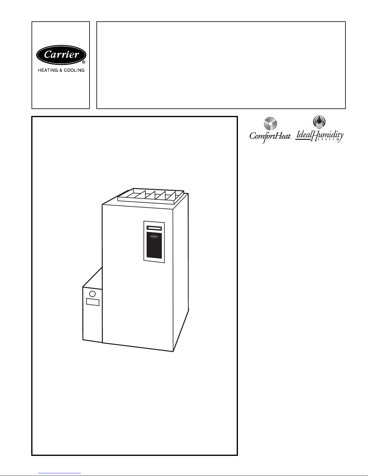
A05069
Product
Data
Infinity™ 96
Model 58MVB
Deluxe 4-Way Multipoise
Variable-Speed
Condensing Gas Furnace
Series 100
Input Rates: 40,000 thru 120,000 Btuh
Comfort Heat™ technology,
the ultimate in
heating comfort . . .
The Carrier Infinity™ 96 with ComfortHeat™ technology achieves the optimum combination of comfort and
efficency.
The Infinity™ 96 achieves industryleading ultra-high efficiency at up to
96.6 percent Annual Fuel Utilization Efficiency (AFUE). Efficient performance
is enhanced through the variable-speed
design. To maintain ideal comfort, ComfortHeat™ technology automatically adjusts the heating level, maximizing the
use of low heating levels that produce
near silent furnace operation while meeting the exact heating needs. This unit is
designed to keep the indoor temperature
within 1 degree of the thermostat setpoint. Because it operates in low heat
most of the time, the Infinity™ 96 uses
up to 80% less power than single-capacity furnaces.
In addition to providing ultimate comfort, the Infinity™ 96 has a sealed combustion system. This system brings
combustion air to the furnace and vents
flue gases outside the furnace in a safe
manner. Because it is sealed, operational
noise is minimal. A sealed combustion
system also means fewer cold drafts and
less air infiltration.
Quality materials are the key behind the
Infinity™ 96’s outstanding performance. Carrier stands behind quality.
We offer lifetime warranty protection*
on the heat exchangers, the heart of the
Infinity™ 96. The rest of the unit is
backed by a limited 5-year warranty.
The Infinity™ 96 is available in 6 heat/
airflow combinations. The unit has a
4-way multipoise design and can be
installed in upflow, downflow, or
Copyright 2005 Carrier Corporation Catalog No. 58MVB-1PD
Page 2

horizontal positions covering up to 24
different applications. The Infinity™ 96
can be installed as a Non-Direct vent/1pipe or Direct vent/2-pipe.
The versatile 4-way multipoise design in
conjunction with variable speed makes
the Infinity™ 96 is ideal for use with splitsystem cooling, including2-speed units. A
Carrier electronic air cleaner, humidifier,
Thermidistat™, comfort ventilator, and
Comfort Zone™ II will provide yearround comfort and efficiency.
Designed for durability, comfort, and reliability, the Infinity™ 96 is the ultimate
in versatile, efficient comfort.
Carrier Infinity® System — When the
Infinity™ 96 variable-speed gas furnace
is matched with the Infinity Control and
an air conditioner or heat pump, you will
experience the ultimate in ComfortHeat™ and Ideal Humidity through unparalleled control of temperature, humidity,
indoor air quality, and zoning. The Carrier Infinity System also provides unprecedented ease of use through onscreen, text-based service reminders and
equipment malfunction alerts.
For even greater comfort and convenience, match the Infinity™ 96 furnace
with an Infinity air conditioner or heat
pump. This will create a fully communicating system, requiring only 4 thermostat wires between system components,
and troubleshooting can even be done
from the outdoor unit without entering
the home.
Optional remote access through telephone or Internet is also available when
combined with a remote connectivity kit.
Infinity™ 96 FEATURES/
BENEFITS
IdealHumidity — The IdealHumidity
system actively controls both temperature and humidity in your home to provide the best comfort all year long. Other
systems depend on heating or cooling to
manage the moisture in the air. But,
IdealHumidity gives you the right
amount of humidity day and night, even
in mild weather.
can do this!
too. By keeping humidity under control,
you can set your thermostat to stay
comfortable and save energy—
20% off your cooling costs!
ComfortHeat™ — On the coldest days
of the year, the Infinity™ 96 Furnace has
the capacity to heat your home. On moderate days when less heat is required, this
furnace will regulate itself to a lower capacity — providing a comfortable home
and minimizing operating costs.
The patented algoritum adjusts the lowheat operating time to match the indoor
conditions.
No other manufacturer
IdealHumidity saves energy,
up to
Reliable Heat Exchanger Design —
The primary heat exchanger is made of
aluminized steel for corrosion resistance.
The patented Serpentuff™ condensing
heat exchanger cells are laminated with
polypropylene for greater resistance to
corrosion and epoxy coated externally to
prevent oxidation. This break-through in
heating technology helps extend the life
of the furnace for years of dependable
performance. The heat exchanger is positioned in the furnace to extract additional heat. Stainless steel 409 heat
exchanger assembly has better corrosion
resistance in natural gas and propane
applications.
Power Heat™ Igniter — Carrier’s
unique SiN igniter is not only physically
robust but it is also electrically robust. It
is capable of running at line voltage and
does not require complex voltage regulators as do other brands. This unique feature further enhances the reliability of
Infinity™ 96 gas furnace and continues
Carrier’s tradition of technology leadership and innovation in providing a reliable and durable product.
ComfortFan™ — Improves comfort
all year long by allowing you to select
the continuous fan speed right at the
thermostat.
SmartEvap™ — Allows your system
to reduce summertime humidity levels
by nearly 10% over standard systems.
Media Filter Cabinet — Enhanced in-
door air quality in your home is made
easier with our media filter cabinet—a
standard accessory on all deluxe fur
naces. When installed as a part of your
system, this cabinet allows for easy and
convenient addition of a Carrier highefficiency air filter.
ComfortHeat™ Control Center —
The microprocessor control center features state-of-the-art combustion, temperature, and airflow control to
maximize comfort while operating at
peak efficiency.
Combustion control is obtained by taking the appropriate inducer motor RPM
readings when the low- and high-fire
pressure switches are made. Using this
information, the microprocessor maintains a consistent air-to-fuel ratio independent of vent sizing and conditions.
The first cycle after power reset provides
16 minutes of low heat before switching
to high heat unless the room thermostat
has been satisfied. Subsequent thermostat cycles provide anywhere from 0 to
16 minutes of low heat depending on the
length of the previous thermostat cycle.
Airflow control is accomplished by using a technique involving the microprocessor and blower motor. The static load
on the air delivery system is measured
each heating cycle. The microprocessor
then uses this information to deliver correct airflow independent of variations in
system restrictions. (For example, dirty
filter or zone damper changes during a
cycle.)
A special dehumidification function allows direct input from a thermidistat or
humidistat. This input adjusts system airflow for greater humidity removal and
increased cooling comfort during summer months.
Warranty — The Infinity™ 96 heat ex-
changers come with a Limited Warranty
for lifetime of original owner in single
family residence; 20 years in other residential and commercial applications.
Five-year limited warranty on entire
unit. Contact your dealer for details.
Direct or Non-Direct Venting — The
Infinity™ 96 can be installed as a 1-pipe
(Non-direct) Vent or 2-pipe (Direct
Vent) furnace. This provides added flexibility to meet diverse installation needs.
Electronic Variable-Speed Motors —
ECM
Motors (Electronically Commutated Motor) provide variable-speed operation to optimize comfort levels in the
home year round. They are also more
economical to operate than standard
motors.
Sealed Combustion System — Infin-
ity™ 96 brings in combustion air from
outside the furnace, which results in especially quiet operation.
Insulation — Foil-faced insulation in
heat exchanger section of the casing
minimizes heat loss.
Insulated Blower Compartment —
The acoustical insulation reduces air and
motor noise for quiet operation.
Monoport Burners — The burners are
finely tuned for smooth, quiet combustion and economical operation.
Bottom Closure — Factory-installed
for side return; easily removable for bottom return.
Blower Access Panel Switch —Auto-
matically shuts off 115-v power to furnace whenever blower access panel is
opened.
Quality Registration — The Infinity™
96 is engineered and manufactured under an ISO 9001 registered quality
system.
Certifications — The Infinity™ 96,
Model 58MVB units are CSA. (A.G.A.
and C.G.A.) design certified for use with
natural and propane gases. The furnace is
factory-shipped for use with natural gas.
An C.S.A. listed gas conversion kit is required to convert furnace for use with
propane gas. The efficiency is GAMA
efficiency rating certified. The Infinity™
96 meets California Air Quality Management District emission requirements.
2
Page 3
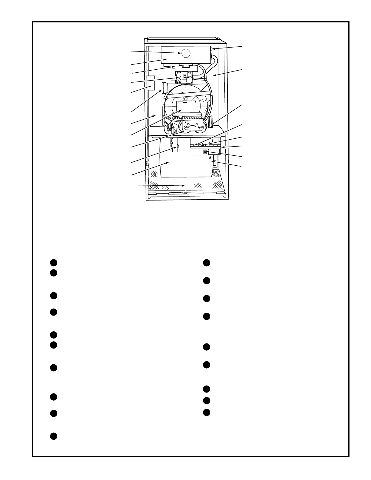
3
10
11
12
1
13
2
14
3
4
5
6
6
7
9
8
16
15
17
18
19
A02287
NOTES:
1. The 58MVB Furnace is built for use with natural gas. The furnace can be converted for propane gas with a factory-authorized and
listed accessory conversion kit.
2. Control location and actual controls may be different than shown above.
Burner sight glass for viewing burner flame.
1
Burner assembly (inside). Operates with energy-
2
saving, inshot burners and hot surface igniter for
safe, dependable heating.
3
Combustion-air intake connection to ensure
contaminant-free air (right or left side).
4
Redundant 2-stage gas valve. Safe, efficient.
Features 1 gas control with 2 internal shutoff
valves.
5
Junction box for 115-v electrical power supply.
6
Vent outlet. Uses PVC pipe to carry vent gases
from the furnace’s combustion system (right or
left side).
7
Secondary condensing heat exchanger (inside).
Wrings out more heat through condensation.
Constructed with patented Polypropylenelaminated steel to ensure durability.
8
Pressure switches ensure adequate flow of flue
products through furnace and out vent system.
9
Inducer motor. Pulls hot flue gases through the
heat exchangers, maintaining negative pressure
for added safety.
10
Condensate drain connection. Collects moisture
condensed during combustion process.
11
Heavy-duty blower. Circulates air across the
heat exchangers to transfer heat into the home.
12
Air filter and retainer. May be used for side
return application.
13
Rollout switch (manual reset) to prevent
overtemperature.
14
Primary serpentine heat exchanger (inside).
Stretches fuel dollars with the S-shaped heatflow design. Solid construction of corrosionresistant aluminized steel means reliability.
15
3-amp fuse provides electrical and component
protection.
16
Light emitting diodes (LEDs) on control center.
Code lights are for diagnosing furnace operation
and service requirements.
17
ComfortHeat™ Control center.
18
Blower access panel safety interlock switch.
Transformer (24v) behind control center
19
provides low-voltage power to furnace control
center and thermostat.
Page 4
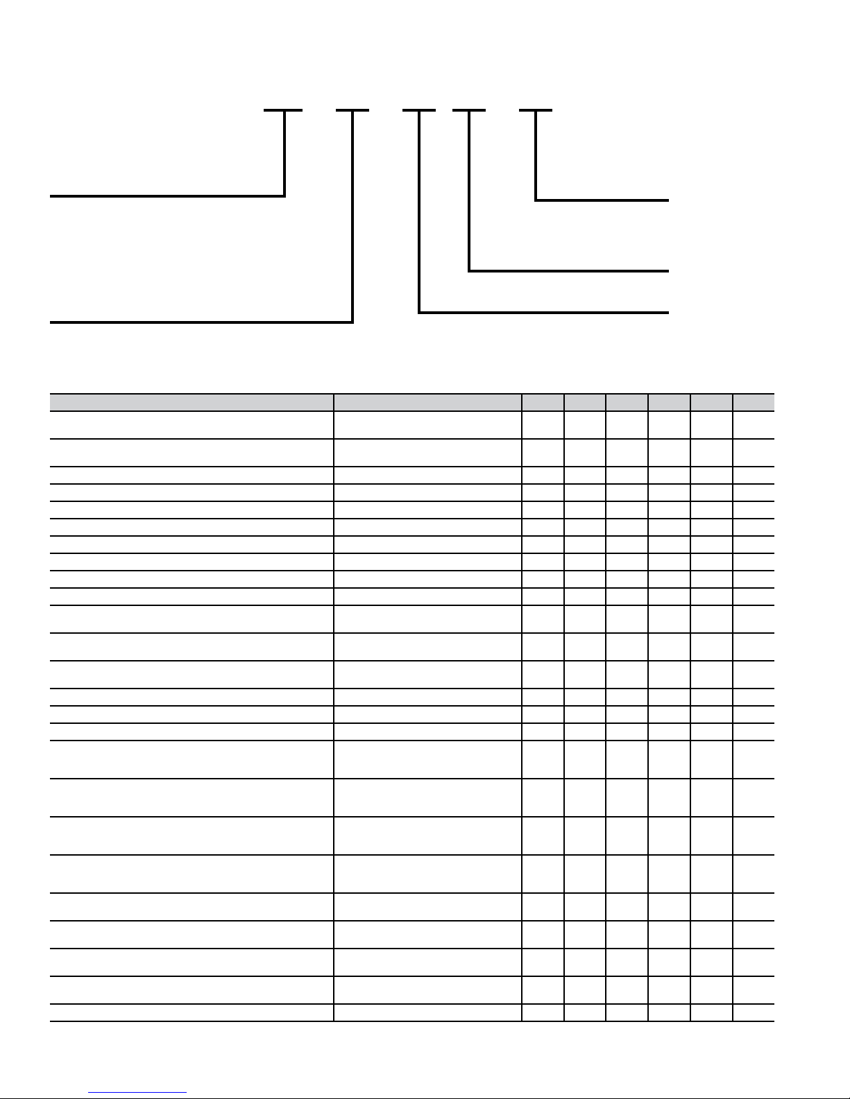
Model number nomenclature
58MVB 040
Deluxe 4-Way Multipoise
Variable-Speed Direct-Vent (2-Pipe) and
Non-Direct Vent (1-Pipe) Condensing Gas
Furnace
F 100 08
Cooling Airflow
(400 CFM per
12,000 Btuh)
14 — 1400 CFM
20 — 2000 CFM
Input Rates
040 — 40,000 Btuh
Series
060 — 60,000 Btuh
080 — 80,000 Btuh
100 — 100,000 Btuh
120 — 120,000 Btuh
Media Filter Cabinet included
Carrier accessories *
UNIT SIZE 040-14 060-14 080-14 080-20 100-20 120-20
VENT TERMINATION KIT (Bracket Only for 2 Pipes)
CONCENTRIC TERMINATION KIT (Single Exit)
CONDENSATE FREEZE PROTECTION KIT
CONDENSATE NEUTRALIZER KIT (obtained thru RCD) P908-0001
ELECTRONIC AIR CLEANER (EAC)‡
MECHANICAL AIR CLEANER
HUMIDIFIER
HEAT RECOVERY VENTILATOR
ENERGY RECOVERY VENTILATOR
UV LIGHTS
EZ FLEX MEDIA FILTER WITH END
CAPS – 16 IN. (9 pack)
EZ FLEX MEDIA FILTER WITH END
CAPS – 20 IN. (9 pack)
EZ FLEX MEDIA FILTER WITH END
CAPS – 24 IN. (6 pack)
REPLACEMENT EZ FLEX FILTER – 16 IN. (10 pack)
REPLACEMENT EZ FLEX FILTER – 20 IN. (10 pack)
REPLACEMENT EZ FLEX FILTER – 24 IN. (10 pack)
EXTERIOR FILTER RACK
(adjustable from 14" to 24") with filter
UNFRAMED FILTER, ONE INCH – 16X25
UNFRAMED FILTER, ONE INCH – 20X25
UNFRAMED FILTER, ONE INCH – 24X25
COMBUSTIBLE FLOOR BASE (not
required when evaporator coil case is used)
NATURAL-TO-PROPANE GAS
CONVERSION KIT (Single Kit)*
PROPANE-TO-NATURAL GAS
CONVERSION KIT (Single Kit)
ECM MOTOR SIMULATOR (replaces the ECM motor
to aid trouble shooting)
DOOR GASKET KIT
–
UNIVERSAL, ONE INCH
2-in. — KGAVT0101BRA
3-in. — KGAVT0201BRA
2-in. — KGAVT0501CVT
3-in. — KGAVT0601CVT
KGAHT0101CFP
Model EACA
Model FILCAB OR EZXCAB
Model HUM
Model HRV
Model ERV
Model UVL
EXPXXLMC0016 X
EXPXXLMC0020 X X X
EXPXXLMC0024 X X
EXPXXFIL0016 X
EXPXXFIL0020 X X X
EXPXXFIL0024 X X
KGAFR0301ALL
KGAFR0306ALL
(6-pack)
KGAWF1301UFR
KGAWF1306UFR
(6-pack)
KGAWF1401UFR
KGAWF1406UFR
(6 pack)
KGAWF1501UFR
KGAWF1506UFR
(6 pack)
KGASB0201ALL X X X X X
KGANP4001ALL
KGAPN3301ALL
KGASD0201FMS X X X X X X
KGBAC0110DGK
See notes at end of table.
XXXXXX
XXXXXX
XXXXXX
XXXXXX
XXXXXX
XXXXXX
XXXXXX
XXXXXX
XXXXXX
XXXXXX
XXXXX
SXSSS
XXX
XX
XXXXXX
XXXXXX
XXXXXX
4
Page 5
*
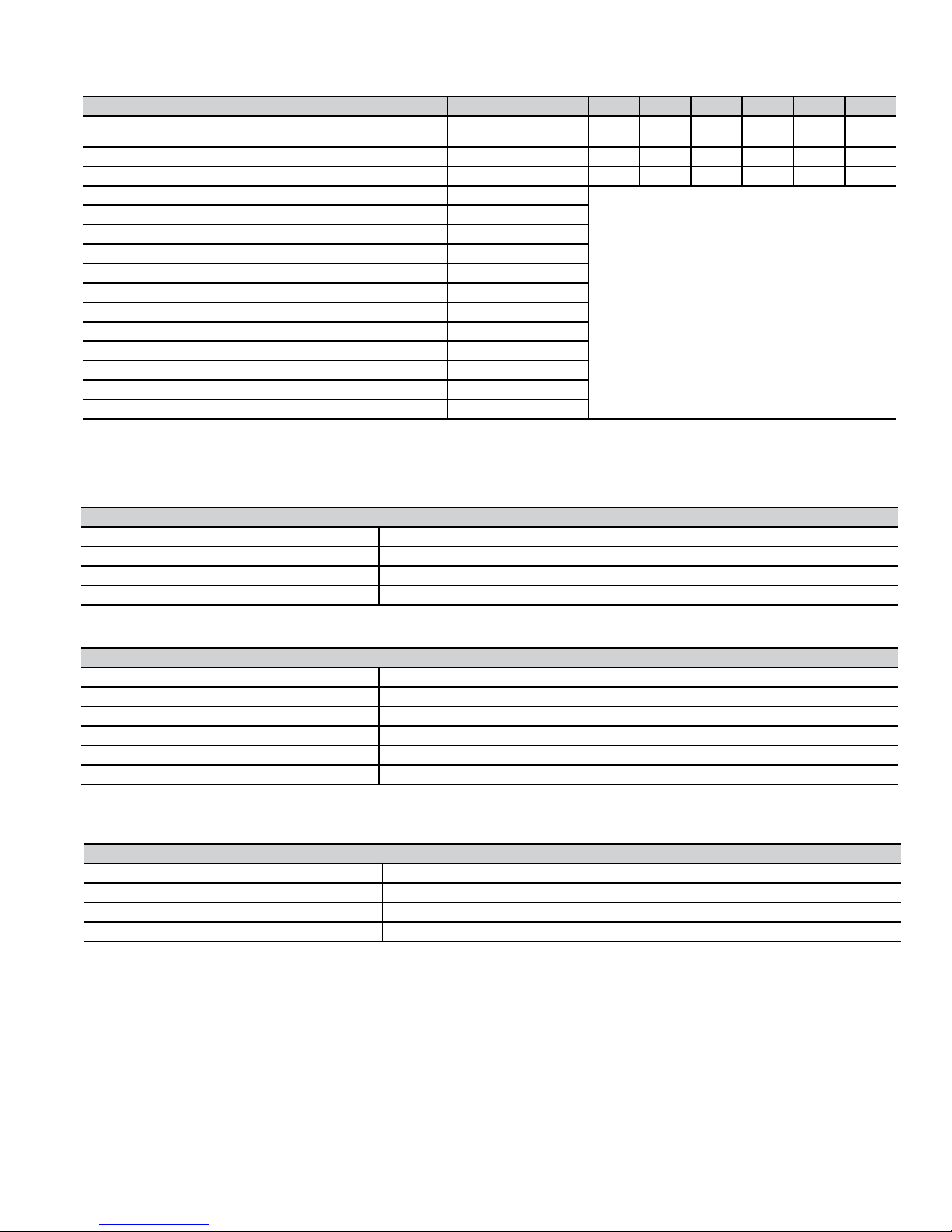
Carrier accessories * continued
UNIT SIZE 040-14 060-14 080-14 080-20 100-20 120-20
ADVANCED PRODUCT MONITOR (software and hardware to link
pc laptop to control board)
ECM CONTROL REPLACEMENT MODULE - 1/2 HP
ECM CONTROL REPLACEMENT MODULE - 1 HP
GAS ORIFICE KIT (Qty 50) Size 42
GAS ORIFICE KIT (Qty 50) Size 43
GAS ORIFICE KIT (Qty 50) Size 44
GAS ORIFICE KIT (Qty 50) Size 45
GAS ORIFICE KIT (Qty 50) Size 46
GAS ORIFICE KIT (Qty 50) Size 47
GAS ORIFICE KIT (Qty 50) Size 48
GAS ORIFICE KIT (Qty 50) Size 54
GAS ORIFICE KIT (Qty 50) Size 55
GAS ORIFICE KIT (Qty 50) Size 56
GAS ORIFICE KIT (Qty 50) 1.25 mm
GAS ORIFICE KIT (Qty 50) 1.30mm
Factory-authorized and field-installed. Gas conversion kits are CSA (A.G.A./C.G.A.) recognized.
S 16 X 25 filters suitable for side return on all furnace sizes.
KGAFP0201APM X X X X X X
HK44EA120 X X X
HK52EA120 X X X
KGAHA0150N42
KGAHA0250N43
KGAHA0350N44
KGAHA0450N45
KGAHA0550N46
KGAHA1550N47
KGAHA1850N48
KGAHA0850P54
KGAHA0750P55
KGAHA0850P56
KGAHA5750125
KGAHA5750130
See Installation Instructions for model,
altitude, and heat value usages.
Thermostat and Zoning Control Options
NON-PROGRAMMABLE THERMOSTAT SELECTION
TSTATCCNAC01-C
TSTATCCNHP01-C*
TSTATCCN2S01-C*
TSTATCCPRH01-B**
* Model HP & 2S thermostat must be field converted to air conditioner operation
** Thermidistat is versatile and can be configured for multiple use & staging, it must be configured for each specific application.
TSTATCCPAC01-B
TSTATCCPHP01-B*
TSTATCCP2S01-B*
TSTATCCSAC01
TSTATCCPDF01-B**
TSTATCCPRH01-B***
* Model HP & 2S thermostat must be field converted to air conditioner operation
** Dual Fuel thermostat is used with furnace and ehat pump application
*** Thermidistat can be configured for multiple use & staging, it must be configured for each specific application.
ZONECC3Z(AC/HP)01
ZONECC2KIT01-B
ZONECC4KIT01-B
ZONECC8KIT01-B
For use with 1-spd. Air Conditioner - deg. F//c, Auto Changeover
For use with 1-spd. Air Conditioner - deg. F/C, Auto Changeover
For use with 2-spd. Air Conditioner - deg. F/C, Auto Changeover
For multi-use / stage configurations - deg. F/C, Auto Changeover
PROGRAMMABLE THERMOSTAT SELECTION
For use with 1-spd. Air Conditioner - deg. F/C, Auto Changeover, 7-Day Programmable
For use with 1-spd. Air Conditioner - deg. F/C, Auto Changeover, 7-Day Programmable
For use with 2-spd. Air Conditioner - deg. F/C, Auto Changeover, 7-Day Programmable
For use with 1-spd. Air Conditioner - deg. F/C, Auto Changeover, 5-2 Programmable
For use with multi-stage applications - deg. F/C, Auto Changeover, 7-Day Programmable
For multi-use / stage configurations - deg. F/C, Auto Changeover, 7-Day Programmable
ZONING CONTROL SELECTION
WeatherMaker Two-Zone kit
Comfort Zone II-B 2-Zone kit
Comfort Zone II-B 4-Zone kit
Comfort Zone II-B 8-Zone kit
5
Page 6
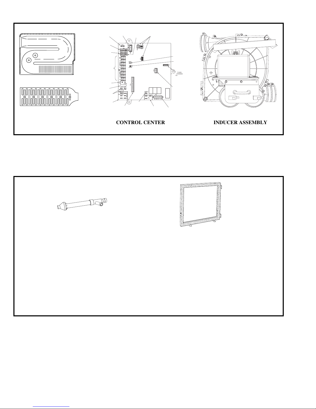
(
HEAT EXCHANGERS
A92505
MODEL PLUG
CONNECTOR
SW1 SETUP
SWITCHES AND
BLOWER OFF-
DELAY
AIR CONDITIONING
(A/C) AIRFLOW
SETUP SWITCHES
24-V THERMOSTAT
TERMINALS
STATUS AND COMM
LED LIGHTS
3-AMP FUSE
TRANSFORMER 24-VAC
CONNECTIONS
115-VAC (L2) NEUTRAL
CONNECTIONS
EAC-1 TERMINAL
115-VAC 1.0 AMP MAX.)
FUTURE
APPLICATIONS
115-VAC (L1) LINE
VOLTAGE CONNECTIONS
HUMIDIFIER
TERMINAL (24-VAC
0.5 AMP MAX.
ACRDJ – AIR
CONDITIONING
RELAY DISABLE
JUMPER
FLASH
UPGRADE
CONNECTOR
(FACTORY
ONLY)
PL3 – ECM BLOWER
HARNESS
CONNECTOR
PL2 – HOT SURFACE
IGNITER & INDUCER
MOTOR CONNECTOR
A02278
CONTINUOUS FAN
COMMUNICATION
CONNECTOR
(CF) AIRFLOW
SETUP SWITCHES
PL1 – LOW VOLTAGE MAIN
HARNESS CONNECTOR
CONTROL CENTER INDUCER ASSEMBLY
A02286
A93086
CONCENTRIC VENT
(DIRECT VENT /
2-PIPE ONLY)
A concentric vent kit allows
vent and combustion-air
pipes to terminate through a
single exit in a roof or side
wall.
One pipe runs inside the other
allowing venting through the
inner pipe and combustion air
to be drawn in through the outer pipe.
A88202
DOWNFLOW
SUBBASE
One base fits all furnace
sizes. The base is designed
to be installed between the
furnace and a combustible
floor when no coil box is used
or when a coil box other than
a Carrier cased coil is used. It
is A.G.A. design certified for
use with Carrier 58MVB furnaces when installed in
downflow applications.
6
Page 7
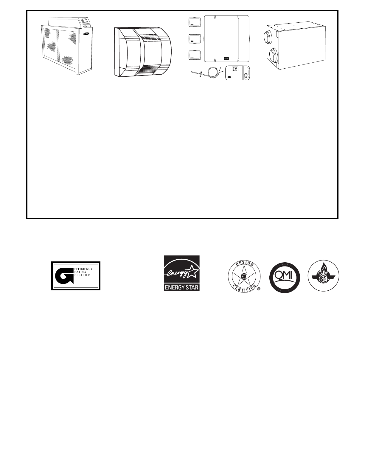
®
A97152
ELECTRONIC OR
MECHANICAL
AIR CLEANER
Cleans the air of smoke, dirt,
and many pollens commonly
found. Saves decorating and
cleaning expenses by keeping carpets, furniture, and
drapes cleaner.
Electronic air cleaner is
shown.
A01484
HUMIDIFIER
By adding moisture to winterdry air, a Carrier humidifier
can often improve comfort
and keeps woodwork, wallpaper, and paint in better
condition. Moisturizing
household air also helps to
retain normal body heat and
provides comfort at lower
temperatures.
A97432
CONTROLS:
THERMOSTATS
AND ZONING
Available in programmable
and non-programmable models, Carrier thermostats maintain a constant, comfortable
temperature level in the
home.
For the ultimate in home
comfort, Carrier’s 2-, 4-, or
8-zone systems allow temperature control of individual
“zones” of the home. This is
accomplished through a
series of electronic dampers
and remote room sensors.
The 4-zone system is shown.
A94336
ENERGY/HEAT
RECOVERY
VENTILATOR
Carrier’s energy or heat
recovery ventilators exhaust
stale indoor air and provide
fresh outdoor air to the home
while minimizing heat loss
and humidity level. Especially
useful for today’s tighter
constructed houses.
Energy recovery ventilator is
shown.
ISO 9001:2000
ama
MEETS DOE RESIDENTIAL CONSERVATION
SERVICES PROGRAM STANDARDS.
Before purchasing this appliance, read important
energy cost and efficiency information available
from your retailer.
As an ENERGY STAR® Partner,
Carrier Corporation has determined that this product meets the
ENERGY STAR® guidelines for energy efficiency.
REGISTERED
REGISTERED QUALITY SYSTEM
These products are engineered and manufactured under an ISO 9001 registered
quality system.
CERTIFIED
®
7
Page 8
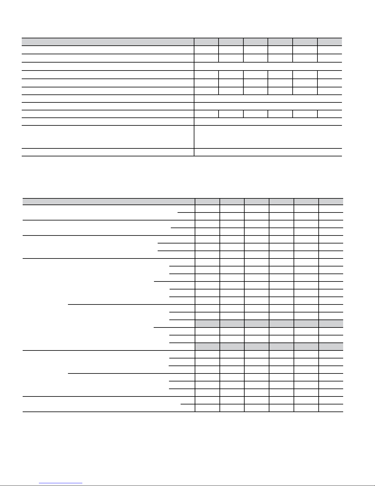
Physical data
UNIT SIZE 040-14 060-14 080-14 080-20 100-20 120-20
DIRECT-DRIVE MOTOR Hp (ECM)
MOTOR FULL LOAD AMPS
RPM (Nominal) — SPEEDS
BLOWER WHEEL DIAMETER X WIDTH (In.)
FILTER SIZE (In.) NOMINAL A(Washable)
SHIPPING WEIGHT (Lb) 205 170 182 204 203 234
LIMIT CONTROL SPST
HEATING BLOWER CONTROL (Off Delay) Selectable 90, 120, 150, or 180 Sec Intervals
BURNERS (Monoport) 234456
GAS CONNECTION SIZE 1/2-in. NPT
GAS VALVE (Redundant) Manufacturer White-Rodgers
Minimum Inlet Pressure (In. wc) 4.5 (Natural Gas)
Maximum Inlet Pressure (In. wc) 13.6 (Natural Gas)
IGNITION DEVICE Hot Surface
1/2 1/2 1/2 1 1 1
7.7 7.7 7.7 12.8 12.8 12.8
Variable 250 — 1300
11 x 10 10 x 7 11 x 10 11 x 10 11 x 10 11 x 10
(1)24 x 25 x 1 (1)16 x 25 x 1 (1)20 x 25 x1 (1)20 x 25 x1 (1)20 x 25 x1 (1)24 x 25 x 1
Performance data
UNIT SIZE 040-14 060-14 080-14 080-20 100-20 120-20
CERTIFIED TEMP RISE RANGE (°F) Low 25 — 55 50 — 80 50 — 80 50 — 80 50 — 80 50 — 80
High 30 — 60 35 — 65 35 — 65 35 — 65 45 — 75 45 — 75
CERTIFIED EXT STATIC PRESSURE (ESP) Heating 0.10 0.12 0.15 0.15 0.20 0.20
(In. wc) Cooling 0.50 0.50 0.50 0.50 0.50 0.50
AIRFLOW CFM‡ Heating Low
Heating High 800 1065 1500 1500 1525 1880
Cooling (Max) 1400 1500 1395 1990 2000 2100
OUTPUT CAPACITY
BTUH* (ICS)
(Shaded capacities
are specified on
rating plate)
AFUE%*
Nonweatherized ICS
INPUT BTUH† Low 26,000 39,000 52,000 52,000 65,000 78,000
Direct Vent (2-Pipe) Low Upflow 25,000 37,000 49,000 49,000 61,000 73,000
Downflow 25,000 36,000 49,000 49,000 61,000 73,000
Horizontal 25,000 36,000 49,000 49,000 61,000 73,000
High Upflow 38,000 57,000 75,000 75,000 94,000 113,000
Downflow 38,000 56,000 75,000 75,000 94,000 113,000
Horizontal 37,000 56,000 75,000 75,000 93,000 112,000
Non-Direct Vent (1-Pipe) Low Upflow 25,000 37,000 49,000 49,000 61,000 73,000
Downflow 25,000 36,000 49,000 49,000 61,000 73,000
Horizontal
High Upflow 38,000 57,000 75,000 75,000 94,000 113,000
Downflow 37,000 56,000 75,000 75,000 94,000 113,000
Horizontal
Direct Vent (2-Pipe) Upflow 96.6 94.1 94.1 94.1 94.1 94.1
Downflow
Horizontal 96.1 93.7 93.7 93.7 93.7 93.7
Non-Direct Vent (1-Pipe) Upflow 96.6 94.1 94.1 94.1 94.1 94.1
Downflow
Horizontal 96.1 93.7 93.7 93.7 93.7 93.7
* Capacity in accordance with U.S. Government DOE test procedures.
† Gas input ratings are certified for elevations to 2000 ft. For elevations above 2000 ft, reduce ratings 2% for each 1000 ft above sea level.
In Canada, derate the unit 5% for elevations from 2000 to 4500 ft above sea level.
‡ Airflow shown is for bottom only return-air supply with factory-supplied 1-in. washable filter(s). For air delivery above 1800 CFM, see Air Delivery
table for other options.
** Low heat CFM when low-heat rise adjustment switch (SW1-3) on furnace control is used.
585(690**) 500 (590**) 720 (850**) 705 (830**) 920 (1085**) 1160 (1370**)
25,000 36,000 49,000 49,000 61,000 73,000
37,000 56,000 75,000 75,000 93,000 112,000
95 92.7 92.7 92.7 92.7 92.7
95.0 92.7 92.7 92.7 92.7 92.7
High 40,000 60,000 80,000 80,000 100,000 120,000
8
Page 9
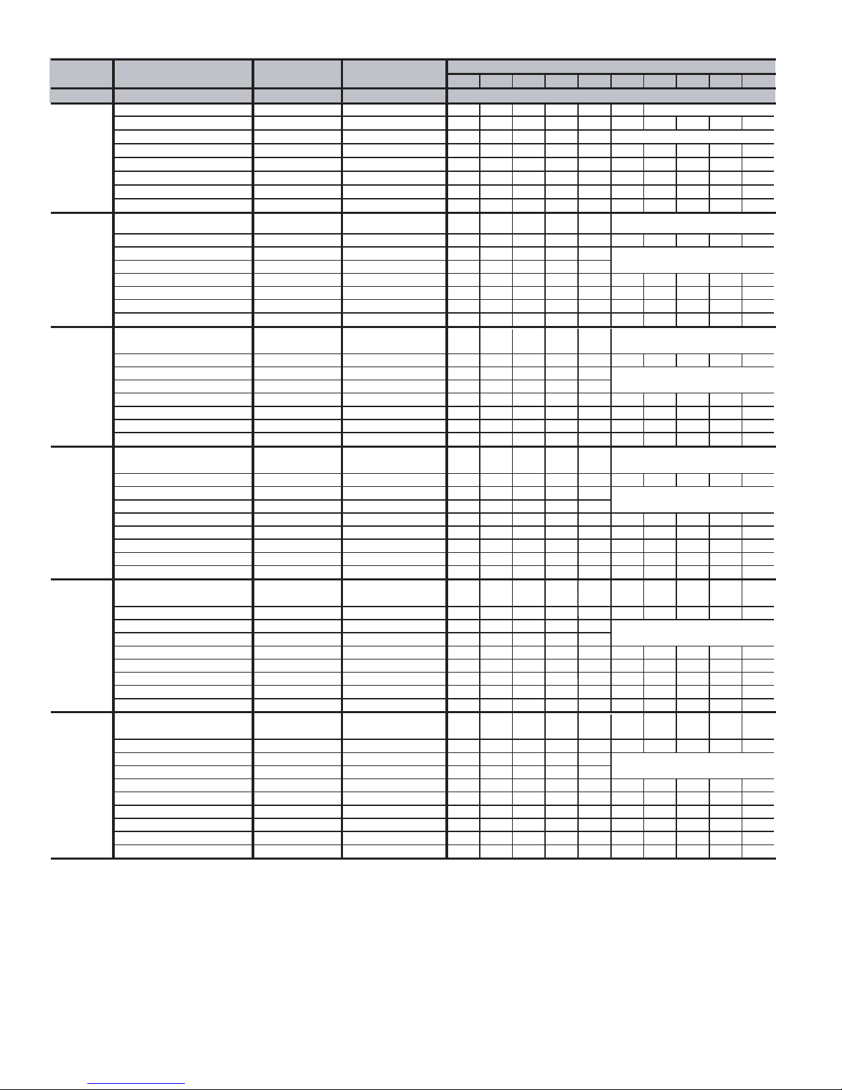
AIR DELIVERY - CFM (Bottom Return With Filter)*
w
)
Unit Operating Mode CFM Airflo
External Static External Static Pressure (ESP)
Size Setting Pressure Range* 0.1 0.2 0.3 0.4 0.5 0.6 0.7 0.8 0.9 1.0
AIRFLOW (CFM
040-14
†† Low Heat 585† 0-0.60 585 580 585 585 585 580
High Heat 800 0-1.0 800 800 800 800 800 790 780 760 750 735
†† 1-1/2-Ton Cooling 525 0-0.50
†† 2-Ton A/C Cooling 700 0-0.90
‡
‡
525 525 505 505 505
675 685 695 695 700 700 700 700 700 700
2-1/2-Ton A/C Cooling 875 0-1.0 875 875 875 875 865 855 835 820 795 720
3-Ton A/C Cooling 1050 0-1.0 1050 1050 1050 1050 1045 1020 1010 995 980 965
3-1/2-Ton A/C Cooling
1225 0-1.0 1225 1225 1225 1225 1225 1225 1220 1210 1195 1175
Maximum 1400 0-1.0 1390 1400 1400 1400 1400 1375 1330 1285 1235 1185
060-14
080-14***
080-20***
100-20***
120-20
††
*** All airflows on 21" casing size furnaces are 5% less on side return only installations.
††
Low Heat 500
High Heat 1065 0-1.0 1055 1065 1065 1065 1065 1065 1065 1065 1060 1050
††
1-1/2-Ton A/C Cooling 525 0-0.50‡ 525 525 510 495 465
††
2-Ton A/C Cooling 700 0-0.50‡ 700 700 695 680 680
2-1/2-Ton A/C Cooling 875 0-1.0‡ 850 870 875 875 870 860 845 825 810 805
3-Ton A/C Cooling 1050 0-1.0 1050 1050 1050 1050 1050 1050 1050 1050 1050 1050
3-1/2-Ton A/C Cooling 1225 0-1.0 1210 1220 1225 1225 1225 1225 1225 1225 1215 1195
Maximum
††
Low Heat 720
High Heat 1500 0-1.0 1500 1500 1470 1420 1375 1330 1290 1250 1210 1170
††
1-1/2-Ton A/C Cooling 525 0-0.50‡ 525 525 515 505 485
††
2-Ton A/C Cooling 700 0-0.50‡ 700 700 695 695 700
2-1/2-Ton A/C Cooling 875 0-1.0‡ 840 855 875 875 875 875 870 855 850 850
3-Ton A/C Cooling 1050 0-1.0‡ 1050 1050 1050 1050 1050 1050 1045 1045 1040 1030
3-1/2-Ton A/C Cooling 1225 0-1.0‡ 1225 1225 1225 1225 1225 1225 1225 1225 1225 1195
Maximum 1400 0-1.0‡ 1400 1400 1400 1400 1395 1355 1315 1275 1230 1190
††
Low Heat 705
High Heat 1500 0-1.0 1500 1500 1500 1500 1500 1500 1500 1495 1485 1480
††
2-Ton A/C Cooling 700 0-0.50‡ 700 670 665 665 655
††
2-1/2-Ton A/C Cooling 875 0-0.50‡ 875 875 875 875 875
3-Ton A/C Cooling 1050 0-1.0‡ 1050 1050 1050 1045 1050 1050 1045 1045 1045 1035
3-1/2-Ton A/C Cooling 1225 0-1.0‡ 1215 1220 1220 1220 1225 1225 1225 1225 1225 1220
4-Ton A/C Cooling 1400 0-1.0‡ 1370 1385 1385 1395 1395 1395 1395 1400 1395 1390
5-Ton A/C Cooling 1750 0-1.0 1750 1750 1750 1750 1750 1750 1745 1740 1735 1725
Maximum 2000 0-1.0 2000 2000 2000 2000 1990 1975 1950 1925 1900 1865
Low Heat 920
High Heat 1525 0-1.0 1525 1525 1525 1525 1520 1515 1515 1515 1515 1515
††
2-Ton A/C Cooling 700 0-0.50‡ 700 700 700 690 685
††
2-1/2-Ton A/C Cooling 875 0-0.50‡ 865 875 870 870 875
3-Ton A/C Cooling 1050 0-1.0‡ 1035 1045 1050 1045 1050 1050 1050 1050 1050 1045
3-1/2-Ton A/C Cooling 1225 0-1.0‡ 1180 1195 1215 1225 1225 1225 1225 1225 1225 1225
4-Ton A/C Cooling 1400 0-1.0‡ 1400 1400 1400 1400 1400 1400 1400 1395 1375 1365
5-Ton A/C Cooling 1750 0-1.0 1740 1745 1750 1750 1750 1750 1750 1750 1750 1740
Maximum 2000 0-1.0 2000 2000 2000 2000 2000 2000 1985 1965 1940 1910
Low Heat 1180
High Heat 1885 0-1.0 1875 1880 1885 1885 1885 1885 1885 1885 1880 1870
††
2-Ton A/C Cooling 700 0-0.50‡ 700 700 700 700 695
††
2-1/2-Ton A/C Cooling 875 0-0.50‡ 875 875 875 870 870
3-Ton A/C Cooling 1050 0-1.0‡ 1035 1040 1050 1050 1050 1050 1050 1025 1005 1000
3-1/2-Ton A/C Cooling 1225 0-1.0‡ 1205 1210 1225 1225 1225 1225 1225 1225 1220 1215
4-Ton A/C Cooling 1400 0-1.0‡ 1390 1400 1400 1400 1400 1400 1395 1385 1370 1360
5-Ton A/C Cooling 1750 0-1.0‡ 1745 1740 1745 1745 1745 1745 1745 1740 1730 1715
6-Ton A/C Cooling 2100 0-1.0 2100 2100 2100 2100 2100 2095 2075 2040 1975 1910
Maximum 2100 0-1.0 2100 2100 2100 2100 2100 2095 2075 2040 1975 1910
Actual external static pressure (ESP) can be determined by using the fan laws (CFM
*
a system with 1750 CFM at 0.5 ESP would operate at high-heating airflow of 1500 CFM at 0.37 ESP and low-heating airflow
of 705 CFM at 0.08 ESP.
†
Low heat CFM when low-heat rise adjustment switch (SW1-3) and comfort/efficiency adjustment switch (SW1-4) on
control center are OFF.
‡ Ductwork must be sized for high-heating CFM within the operational range of ESP.
** Wattage data provided is for the circulating blower with bottom return and does not include draft inducer, accessories,
or gas controls.
Operation within the blank areas of the chart is not recommended because high-heat operation will be above 1.0 ESP.
†
1400 0-1.0 1400 1400 1400 1400 1400 1400 1400 1400 1385 1345
†
†
†
†
0-0.50 500 495 485 460 430
0-0.50 720 715 715 720 720
0-0.50 705 680 680 675 675
0-1.0 920 915 915 920 920 920 915 900 895 890
0-1.0 1160 1175 1180 1180 1180 1180 1180 1180 1180 1180
2
proportional to ESP); such as,
9
Page 10
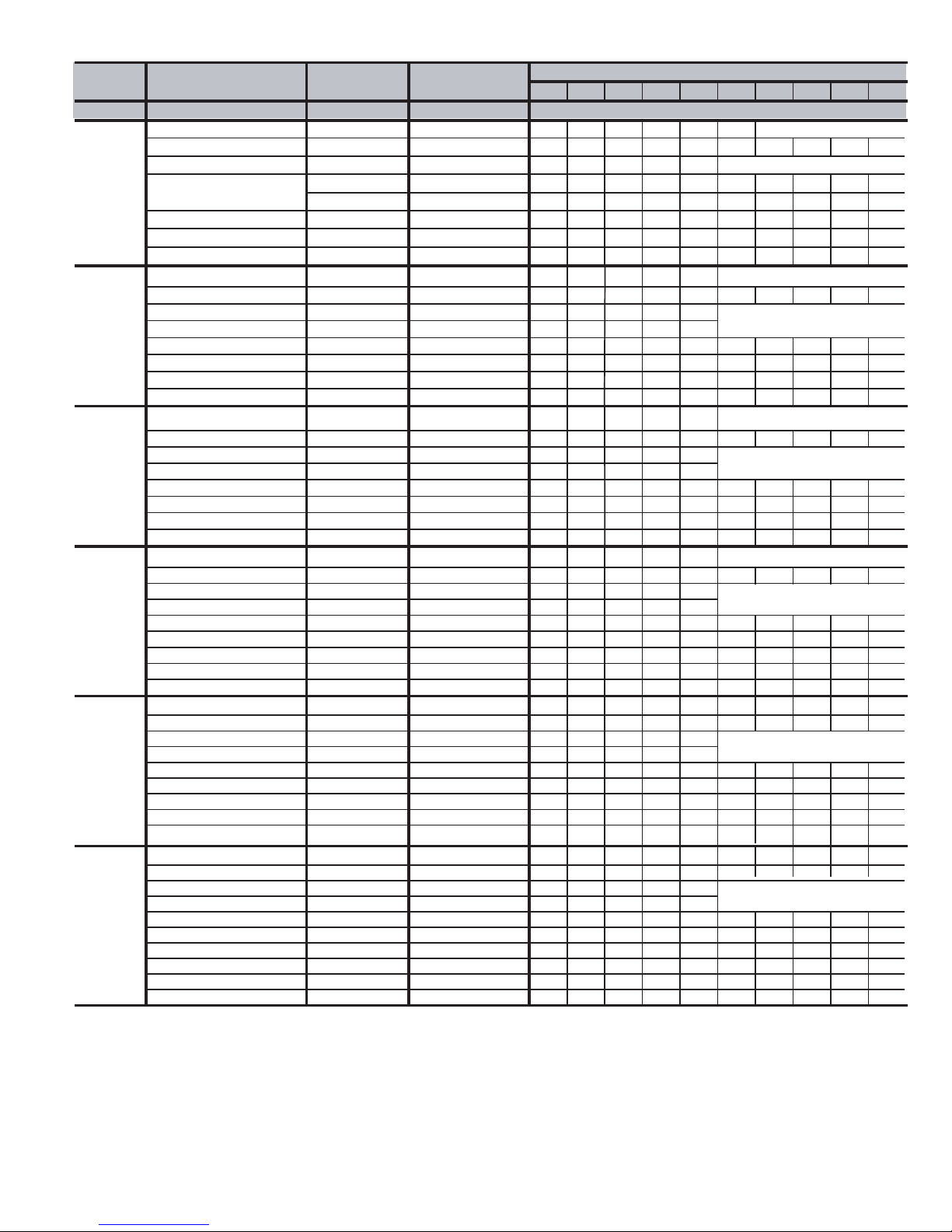
AIR DELIVERY - POWER DRAW (WATTS)**
Unit Operating Mode CFM Airflow External Static External Static Pressure (ESP)
Size Setting Pressure Range* 0.1 0.2 0.3 0.4 0.5 0.6 0.7 0.8 0.9 1.0
POWER DRAW (WATTS)**
††
040-14
060-14
080-14***
080-20***
100-20***
120-20
Low Heat 585
High Heat 800 0-1.0 97 119 141 165 187 209 230 252 274 292
††
1-1/2-Ton Cooling 525 0-0.50
††
2-Ton A/C Cooling 700 0-0.90
2-1/2-Ton A/C Cooling 875 0-1.0 112 138 164 188 210 236 256 275 295 317
3-Ton A/C Cooling 1050 0-1.0 167 202 233 263 288 307 334 364 388 417
3-1/2-Ton A/C Cooling
Maximum 1400 0-1.0 317 379 425 475 527 535 542 546 551 563
††
Low Heat 500
High Heat 1065 0-1.0 150 175 200 234 264 292 321 352 378 408
††
1-1/2-Ton A/C Cooling 525 0-0.50
††
2-Ton A/C Cooling 700 0-0.50
2-1/2-Ton A/C Cooling 875 0-1.0
3-Ton A/C Cooling 1050 0-1.0 149 174 199 233 263 291 320 351 377 407
3-1/2-Ton A/C Cooling 1225 0-1.0 210 248 278 312 344 384 418 449 476 503
Maximum
††
Low Heat 720
High Heat 1500 0-1.0 442 507 519 527 535 543 550 557 564 572
††
1-1/2-Ton A/C Cooling 525 0-0.50
††
2-Ton A/C Cooling 700 0-0.50
2-1/2-Ton A/C Cooling 875 0-1.0
3-Ton A/C Cooling 1050 0-1.0
3-1/2-Ton A/C Cooling 1225 0-1.0
Maximum 1400 0-1.0
††
Low Heat 705
High Heat 1500 0-1.0 381 432 478 511 564 610 650 688 732 761
††
2-Ton A/C Cooling 700 0-0.50
††
2-1/2-Ton A/C Cooling 875 0-0.50
3-Ton A/C Cooling 1050 0-1.0
3-1/2-Ton A/C Cooling 1225 0-1.0
4-Ton A/C Cooling 1400 0-1.0
5-Ton A/C Cooling 1750 0-1.0 587 631 664 724 772 815 861 907 943 988
Maximum 2000 0-1.0 839 911 973 1029 1066 1104 1134 1149 1170 1182
Low Heat 920
High Heat 1525 0-1.0 378 419 448 486 518 561 606 650 696 730
††
2-Ton A/C Cooling 700 0-0.50
††
2-1/2-Ton A/C Cooling 875 0-0.50
3-Ton A/C Cooling 1050 0-1.0
3-1/2-Ton A/C Cooling 1225 0-1.0
4-Ton A/C Cooling 1400 0-1.0
5-Ton A/C Cooling 1750 0-1.0 502 558 602 657 715 754 797 847 889 930
Maximum 2000 0-1.0 766 819 887 947 991 1030 1065
Low Heat 1180
High Heat 1885 0-1.0 547 607 652 715 756 816 870 912 958 1000
††
2-Ton A/C Cooling 700 0-0.50
††
2-1/2-Ton A/C Cooling 875 0-0.50
3-Ton A/C Cooling 1050 0-1.0
3-1/2-Ton A/C Cooling 1225 0-1.0
4-Ton A/C Cooling 1400 0-1.0
5-Ton A/C Cooling 1750 0-1.0
6-Ton A/C Cooling 2100 0-1.0 794 867 931 996 1042 1092 1135 1152 1124 1098
Maximum 2100 0-1.0 592 673 746 811 885 935 994 1026 1102 1129
†
0-0.60 55 71 91 108 129 147
‡
‡
49 63 75 94 107
67 92 117 134 159 186 216 239 267 296
1225 0-1.0 232 266 308 341 380 413 448 491 524 561
†
0-0.50 43 55 70 83 97
‡
‡
‡
46 62 74 91 104
69 86 105 124 138
101 126 154 179 202 226 248 267 287 313
1400 0-1.0 311 341 384 420 455 495 529 568 602 612
†
†
†
†
0-0.50 80 95 118 142 168
‡
‡
‡
‡
‡
‡
50 63 80 96 111
73 94 113 133 156
102 133 161 191 218 241 268 291 320 348
168 206 240 273 299 324 356 385 418 460
245 277 317 355 394 431 481 522 558 568
376 422 478 520 527 537 544 553 560 568
0-0.50 76 90 112 129 149
‡
‡
‡
‡
‡
76 89 109 127 148
113 136 157 178 208
158 191 213 239 266 300 326 351 392 425
227 262 294 322 360 390 432 459 501 538
298 340 384 417 458 493 534 574 607 647
0-1.0 113 136 159 186 221 243 263 285 316 340
‡
‡
‡
‡
‡
74 89 109 126 146
99 124 147 168 200
144 177 207 229 258 288 319 350 385 415
189 223 268 306 346 377 399 447 488 517
283 328 360 400 439 474 510 541 575 598
1129 1152
1101
0-1.0 162 194 228 265 297 325 363 392 432 459
‡
‡
‡
‡
‡
‡
72 89 113 128 146
98 119 140 163 187
126 156 194 221 249 279 307 327 351 381
178 211 253 284 314 352 382 424 455 494
257 310 348 388 421 458 488 528 557 591
461 498 552 618 665 711 760 800 847 888
Actual external static pressure (ESP) can be determined by using the fan laws (CFM
*
a system with 1750 CFM at 0.5 ESP would operate at high-heating airflow of 1500 CFM at 0.37 ESP and low-heating airflow
of 705 CFM at 0.08 ESP.
†
Low heat CFM when low-heat rise adjustment switch (SW1-3) and comfort/efficiency adjustment switch (SW1-4) on
control center are OFF.
‡
Ductwork must be sized for high-heating CFM within the operational range of ESP.
** Wattage data provided is for the circulating blower with bottom return and does not include draft inducer, accessories,
or gas controls.
††
Operation within the blank areas of the chart is not recommended because high-heat operation will be above 1.0 ESP.
*** All airflows on 21" casing size furnaces are 5% less on side return only installations.
10
2
proportional to ESP); such as,
Page 11
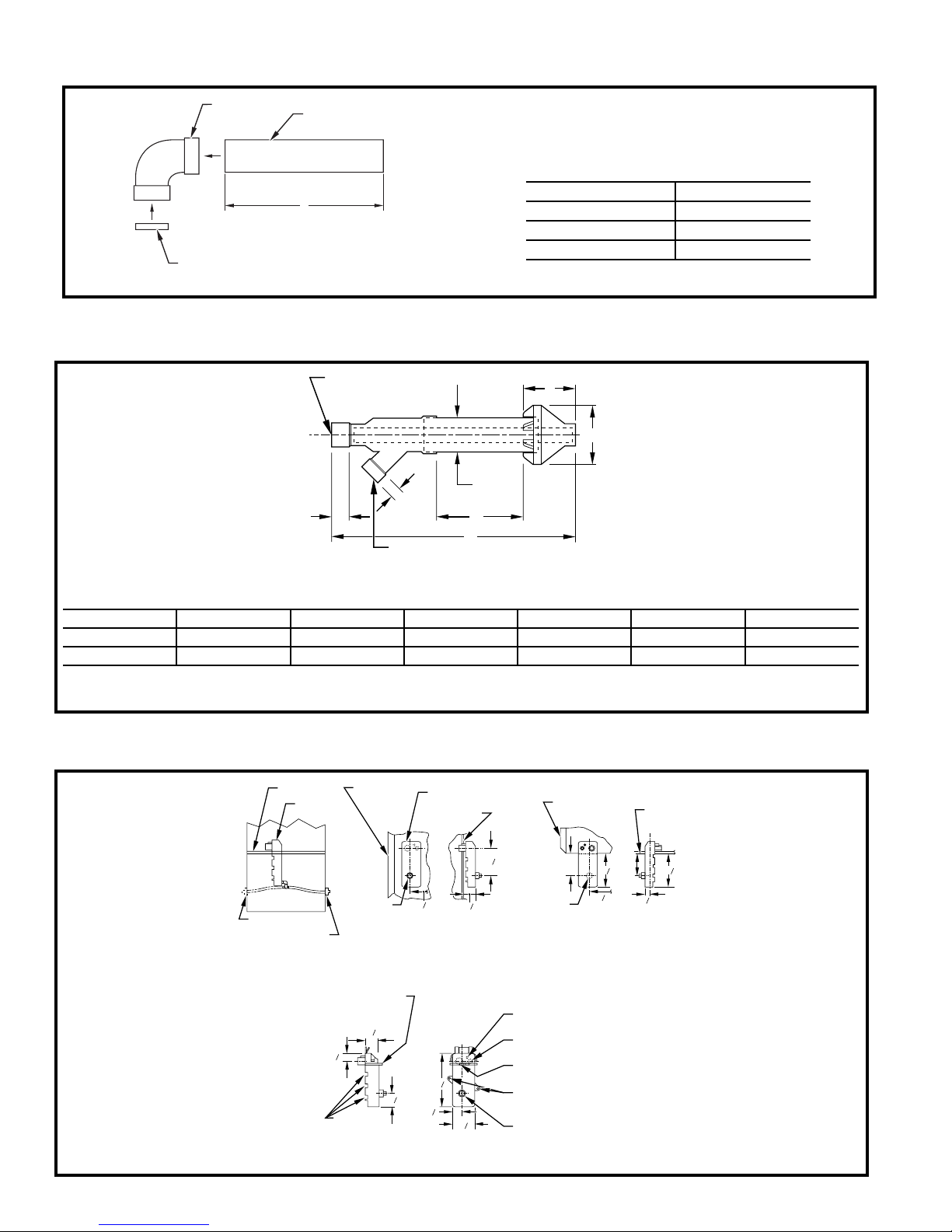
Dimensions
COMBUSTION-AIR PIPE FOR NON-DIRECT (1-PIPE) VENT APPLICATION (SIZES 040 THROUGH 120 ONLY)
FIELD-SUPPLIED
2-IN. DIAMETER
PVC 90 ELBOW
COMBUSTION-AIR DISC
(FACTORY-SUPPLIED IN
LOOSE PARTS BAG)
CONCENTRIC VENT (DIRECT VENT/2-PIPE ONLY) (ALL MODEL SIZES)
FIELD-SUPPLIED
2-IN. DIAMETER
PVC PIPE
A
A96211
B IN. DIA PVC
VENT/EXHAUST
LENGTH OF STRAIGHT
PIPE PORTION OF COMBUSTION
AIR INLET PIPE ASSEMBLY (IN.)
CASING WIDTH A
17-1/2 8-1/2 ± 1/2
21 10-1/2 ± 1/2
24-1/2 12 ± 1/2
F
E
13/16
C IN. DIA
1
/2
1
B IN. DIA PVC
INTAKE/COMBUSTION AIR
D
A
A97110
DIMENSIONS (in.)
KIT PART NO. A* BCD†EF
KGAVT0501CVT 33-3/8 2 3-1/2 16-5/8 6-1/4 5-3/4
KGAVT0601CVT 38-7/8 3 4-1/2 21-1/8 7-3/8 6-1/2
* Dimension A will change accordingly as dimension D is lengthened or shortened.
† Dimension D may be lengthened to 60 in. maximum. Dimension D may also be shortened by cutting the pipes provided in the kit to 12 in. minimum.
CONDENSATE TRAP
BLOWER SHELF
CONDENSATE
TRAP (INSIDE)
ALTERNATE DRAIN
TUBE LOCATION
CONDENSATE TRAP
DRAIN TUBE LOCATION
UPFLOW APPLICATIONS
FURNACE
DOOR
FIELD
DRAIN
CONN
EXTERNAL UPFLOW APPLICATIONS
CONDENSATE
TRAP
FURNACE
SIDE
7
4
8
1
26
SIDE VIEW FRONT VIEW END VIEW FRONT VIEW
DOWNFLOW AND ALTERNATE
1
4
1
2
FURNACE
DOOR
FIELD
DRAIN
CONN
4
26
APPLICATIONS
3
5
1
4
HORIZONTAL
FURNACE
SIDE
3
4
5
4
4
3
4
SLOT FOR SCREW
HORIZONTAL
APPLICATION
(OPTIONAL)
1
1
2
3
4
1
8
7
3
1
4
7
WIRE TIE
GUIDES
(WHEN USED)
FRONT VIEW SIDE VIEW
8
1
⁄4 OD
COLLECTOR BOX TO
TRAP RELIEF PORT
1
⁄2 OD
INDUCER HOUSING
DRAIN CONNECTION
5
⁄8 OD
COLLECTOR BOX
DRAIN CONNECTION
SCREW HOLE FOR
UPFLOW OR DOWNFLOW APPLICATIONS
1
2
4
(OPTIONAL)
1
⁄2-IN. PVC OR CPVC
A93026
11
Page 12
"
8
⁄
"
16
"
16
⁄
13
⁄
5
"
8
⁄
5
7
39
1"
"
"
16
⁄
16
⁄
7
11
"
16
⁄
5
19"
"
22
4
⁄
1
"
16
⁄
15
"
2
⁄
26
1
28
AIRFLOW
OUTLET
26
2-IN. COMBUSTION-
AIR CONN
"
16
⁄
9
TYP
TRAP LOCATION
"
16
⁄
CONDENSATE DRAIN
13
A
D
OUTLET
"
16
⁄
13
⁄2-IN. DIA
1
(DOWNFLOW &
OR ALTERNATE
HORIZONTAL RIGHT)
GAS CONN
-IN. DIA GAS CONN
2
⁄
1
⁄8-IN. DIA
POWER CONN
7
"
4
⁄
1
TYP
33
5
"
8
⁄
32
⁄2-IN. DIA
1
THERMOSTAT ENTRY
TYP
13
"
16
⁄
30
"
2
⁄
1
30
2-IN. VENT CONN
"
16
⁄
11
29
TYP
5
"
16
⁄
11
22
SIDE INLET
"
4
⁄
1
18
1
" TYP
4
⁄
22
"
16
⁄
3
24
(UPFLOW)
BOTTOM INLET
HANGING
CONDENSAT E
DRAIN LOCATION
FOR HORIZONTAL
DIMPLE LOCATORS
"
16
⁄
11
-in. rectangle.
-in. rectangle.
2
4
/
/
1
1
INLET
"
16
⁄
11
x 19
x 23
2
2
x 12-in. rectangle.
/
/
2
1
1
/
1
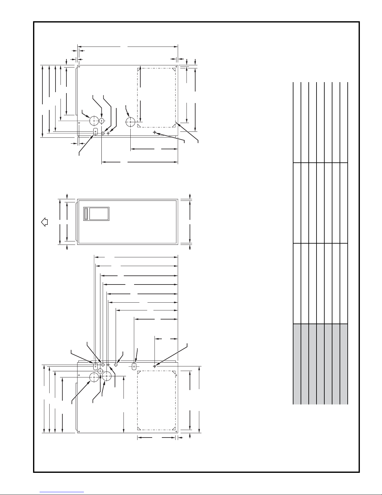
DIMENSIONS (In.)
"
8
⁄
27
"
16
⁄
9
TYP
"
27
2
⁄
1
24
"
16
⁄
5
17
see flex duct manufacturerís recommendations for equivalent diameters.
a. For 800 CFM–16-in. round or 14
2. Minimum return-air opening at furnace:
b. For 1200 CFM–20-in. round or 14
c. For 1600 CFM–22-in. round or 14
d. For airflow requirements above 1800 CFM, see Air Delivery table in Product Data
literature for specific use of single side inlets. The use of both side inlets, a
combination of 1 side and the bottom, or the bottom only will ensure adequate
return air openings for airflow requirements above 1800 CFM at 0.5” W.C. ESP.
A05053
⁄8-IN. DIA
POWER CONN
7
CONDENSATE DRAIN
TRAP LOCATION
(DOWNFLOW &
HORIZONTAL LEFT)
"
16
⁄
15
"
4
⁄
1
26
"
2
⁄
1
26
"
16
⁄
24
5
22
-IN. COMBUSTION2
AIR CONN
1
-IN. DIA
2
⁄
GAS CONN
-IN. VENT CONN
2
⁄8-IN. DIA
ACCESSORY
7
ENTRY
"
16
⁄
11
22
⁄2-IN. DIA THERMOSTAT
1
12
POWER ENTRY
CONDENSAT E
DRAIN TRAP
LOCATION
(ALTERNATE
UPFLOW)
SIDE INLET
"
2
⁄
1
TYP
14
"
16
⁄
7
TYP
9
"
4
⁄
1
1
CONDENSAT E
DRAIN LOCATION
" TYP
4
⁄
1
23
SIDE INLET
1" E
(UPFLOW)
" TYP
16
⁄
15
26
NOTES: 1. Minimum return-air openings at furnace, based on metal duct. If flex duct is used,
040-14* 24-1/2* 22-7/8* 23*
060-14 17-1/2 15-7/8 16
080-14 21 19-3/8 19-1/2
080-20 21 19-3/8 19-1/2
100-20 21 19-3/8 19-1/2
UNIT SIZE A D E
120-20 24-1/2 22-7/8 23
* These dimensions reflect the wider casing for the 96.6% AFUE furnace.
Page 13
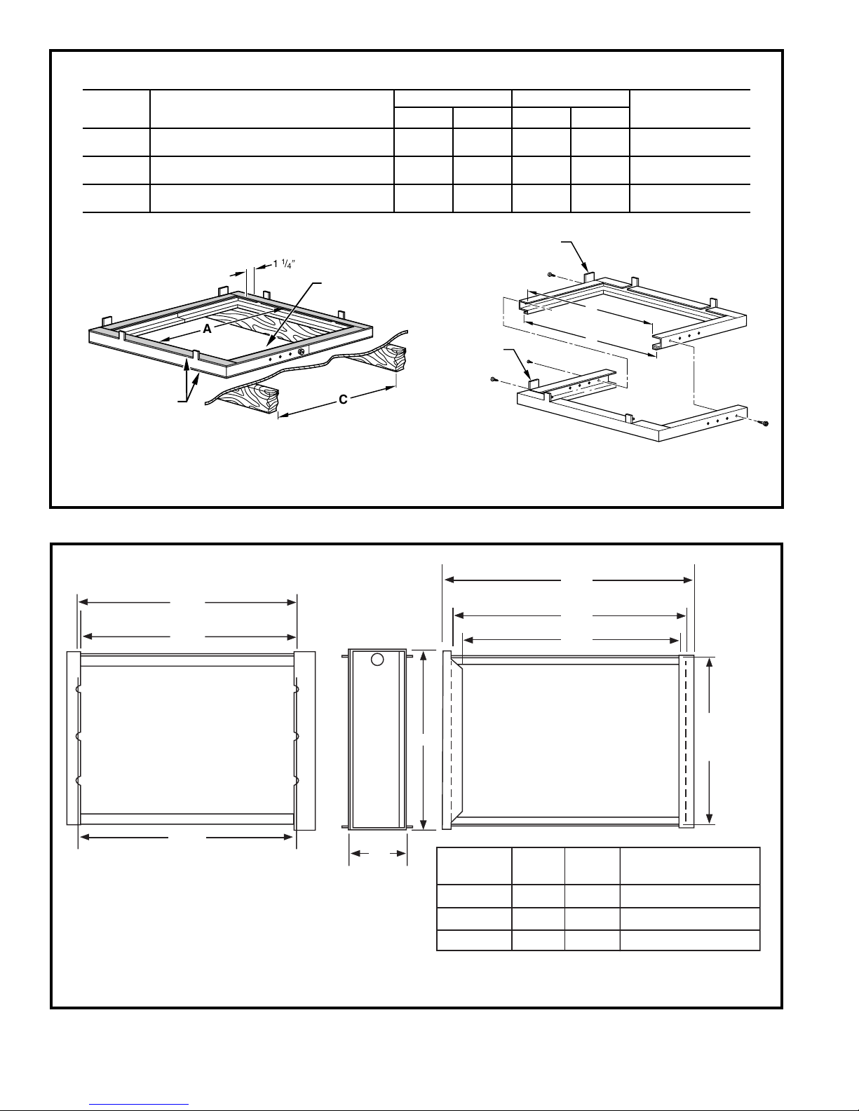
DOWNFLOW SUBBASE
DIMENSIONS (In.)
FURNACE
CASING
WIDTH
17-1/2
21
24-1/2
FURNACE IN DOWNFLOW APPLICATION
Furnace with or without Cased Coil
Assembly or Coil Box
Furnace with or without Cased Coil
Assembly or Coil Box
Furnace with or without Cased Coil
Assembly or Coil Box
PLENUM OPENING* FLOOR OPENING HOLE NO.
ABCD
15-1/8 19 16-3/4 20-3/8 3
18-5/8 19 20-1/4 20-3/8 2
22-1/8 19 23-3/4 20-3/8 1
* The plenum should be constructed 1/4-in. smaller in width and depth than the plenum dimensions shown above.
LOCATING
1 1/
″ TYP
4
PLENUM
OPENING
TAB
B
FACTORY-SUPPLIED
FIELD-INSTALLED
INSULATION
A
Assembled
C
A97427
LOCATING
TAB
D
Disassembled
FOR WIDTH
ADJUSTMENT
4
3
2
1
3
4
A88207
1
2
5
/
23
8"
3
/
8"
23
Furnace Side
3
/
23
Centerline Screw Slots
4"
MEDIA FILTER CABINET
A
3
/
4"
5
Media
Filter Cabinet
16" 17" 16"
20" 21" 20"
24" 25" 24"
5
/
25
8"
3
/
24
Opening with Flanges Bent
8"
1
/
23
8"
Opening
Duct Side
AB
gninepO B
Shipped with sizes
060-12, 080-12, 080-16
100-16, 100-20
120-20
A05186
13
Page 14
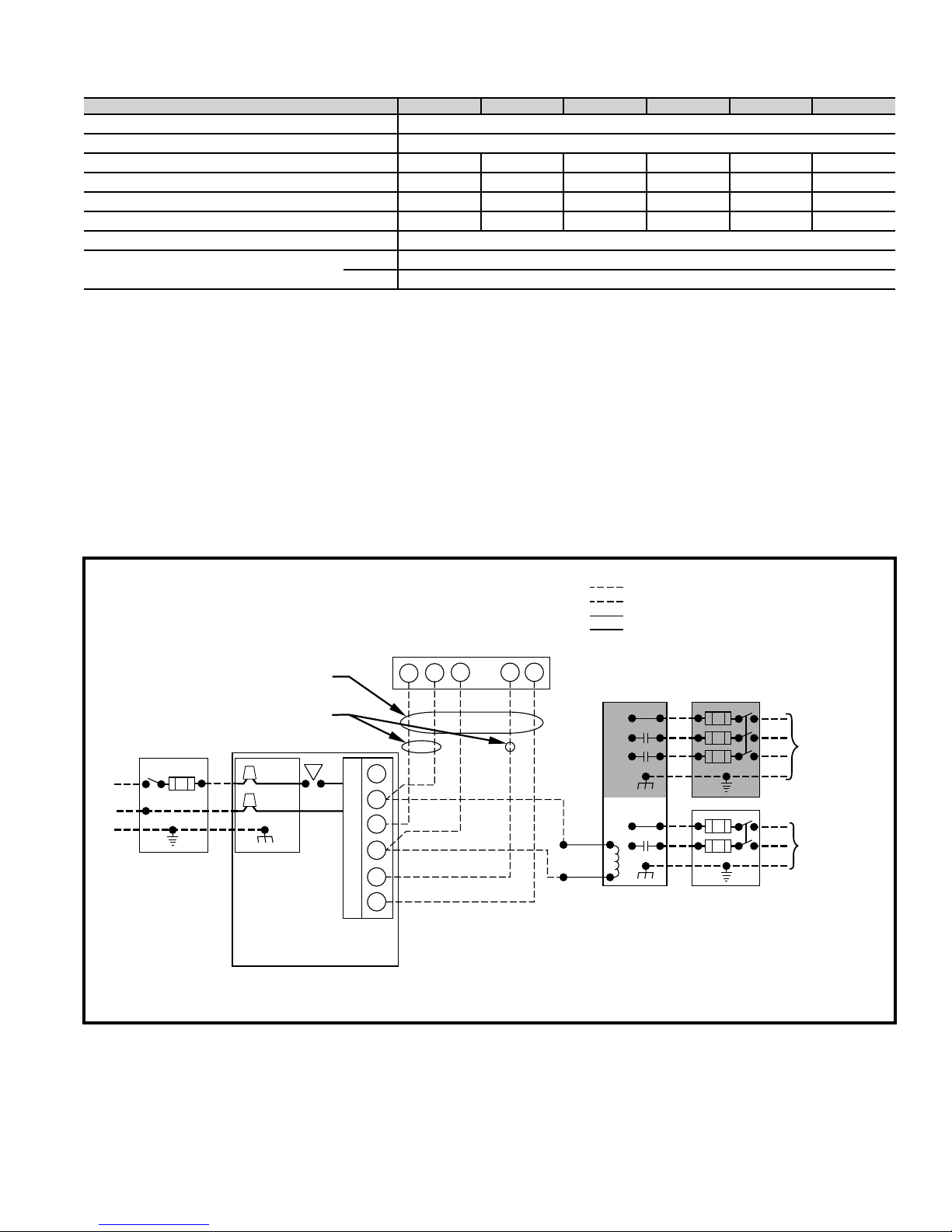
Electrical data
UNIT SIZE 040-14 060-14 080-14 080-20 100-20 120-20
UNIT VOLTS — HERTZ — PHASE 115 — 60 — 1
OPERATING VOLTAGE RANGE (Min — Max)
MAXIMUM UNIT AMPS 8.9 8.9 8.9 13.8 13.8 13.8
MINIMUM WIRE SIZE 14 14 14 12 12 12
MAXIMUM WIRE LENGTH (Ft)‡ 31 31 31 32 32 32
MAXIMUM FUSE OR CKT BKR (Amps)
TRANSFORMER (24v) 40va
EXTERNAL CONTROL POWER AVAILABLE Heating 25va
* Permissible limits of the voltage range at which the unit will operate satisfactorily.
‡ Length shown is as measured 1 way along wire path between unit and service panel for maximum 2% voltage drop.
** Time-delay type is recommended.
* 104 — 127
** 15 15 15 20 20 20
Cooling 34va
Typical wiring schematic
NOTE 2
WC Y RG
W2
COM
W/W1
NOTE 1
Y/Y2
R
G
NOTES: 1.
BLK
WHT
GND
115-VOLT FIELD-
SUPPLIED
FUSED
DISCONNECT
BLK
WHT
JUNCTION
BOX
FIVE
WIRE
THREE-WIRE
HEATING-
ONLY
CONTROL
BOX
FURNACE
24-VOLT
TERMINAL
BLOCK
FIELD 24-VOLT WIRING
FIELD 115-, 208/230-, 460-VOLT WIRING
FACTORY 24-VOLT WIRING
FACTORY 115-VOLT WIRING
1-STAGE
THERMOSTAT
TERMINALS
FIELD-SUPPLIED
FUSED DISCONNECT
208/230- OR
460-VOLT
THREE
PHASE
208/230VOLT
SINGLE
GND
PHASE
CONDENSING
UNIT
Connect Y/Y2-terminal as shown for proper operation.
Some thermostats require a "C" terminal connection as shown.
2.
If any of the original wire, as supplied, must be replaced, use
3.
same type or equivalent wire.
14
A95236
Page 15
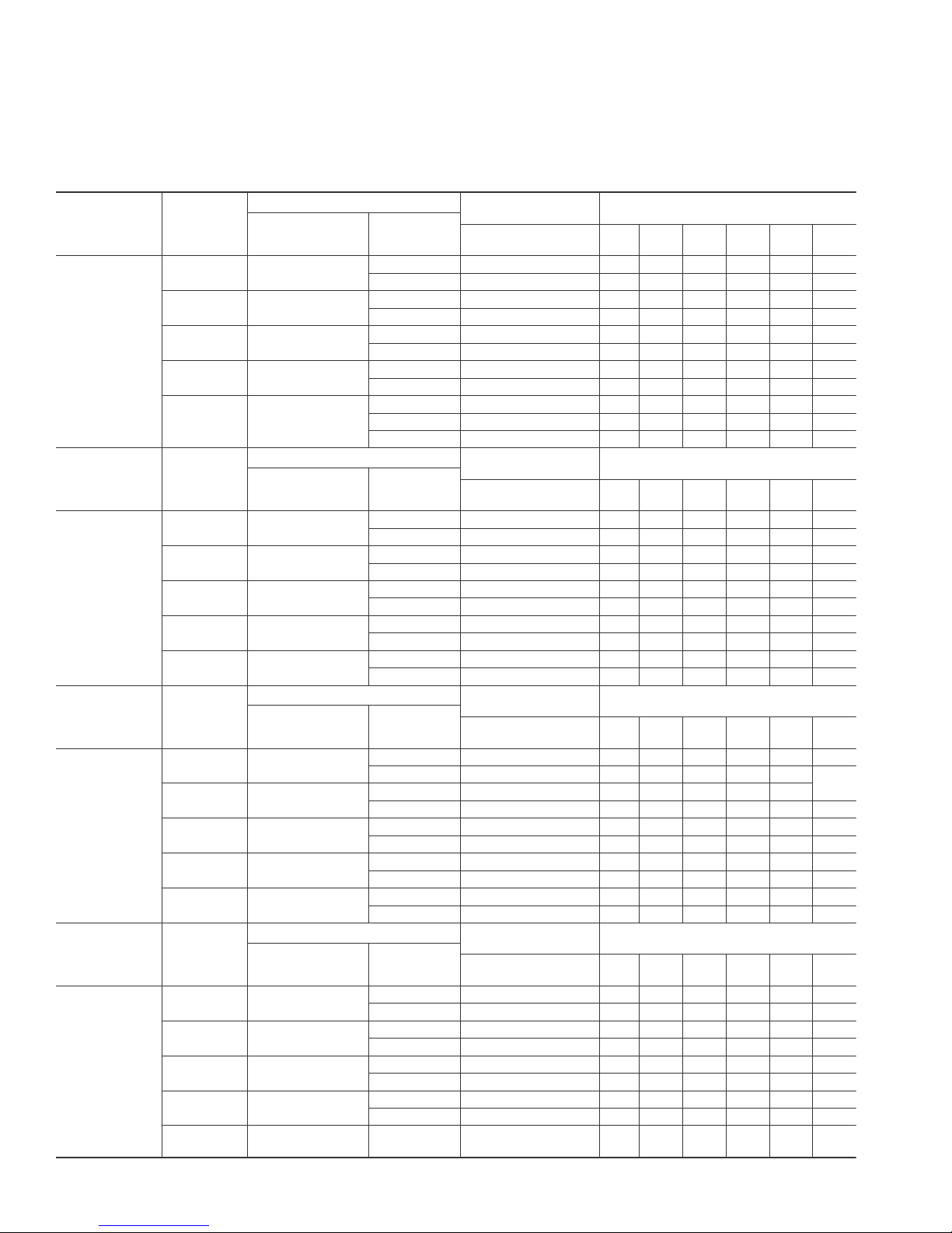
Combustion-air and vent piping for Direct Vent/2-Pipe
(All Sizes) and Non-Direct Vent/1-Pipe (Sizes 040
through 120 Only) Applications
Maximum Allowable Pipe Length (Ft)
NON-DIRECT VENT
(1-PIPE) ONLY
Pipe Dia
(IN.)*
NON-DIRECT VENT
(1-PIPE) ONLY
Pipe Dia
(IN.)*
NON-DIRECT VENT
(1-PIPE) ONLY
Pipe Dia
(IN.)*
NON-DIRECT VENT
(1-PIPE) ONLY
Pipe Dia
(IN.)*
NUMBER OF 90° ELBOWS
12 3 456
NUMBER OF 90° ELBOWS
12 3 456
NUMBER OF 90° ELBOWS
12 3 456
NUMBER OF 90° ELBOWS
12 3 456
ALTITUDE
0to2000
ALTITUDE
2001 to 3000
ALTITUDE
3001 to 4000
ALTITUDE
4001 to 5000‡
See notes on page 17.
UNIT SIZE
(BTUH)
40,000
60,000
80,000
100,000
120,000
UNIT SIZE
(BTUH)
40,000
60,000
80,000
100,000
120,000
UNIT SIZE
(BTUH)
40,000
60,000
80,000
100,000
120,000
UNIT SIZE
(BTUH)
40,000
60,000
80,000
100,000
120,000
DIRECT VENT (2-PIPE) ONLY
Termination
Type
2 Pipe or 2-In.
Concentric
2 Pipe or 2-In.
Concentric
2 Pipe or 2-In.
Concentric
2 Pipe or 2-In.
Concentric
2 Pipe or 3-In.
Concentric
DIRECT VENT (2-PIPE) ONLY
Termination
Type
2 Pipe or 2-In.
Concentric
2 Pipe or 2-In.
Concentric
2 Pipe or 2-In.
Concentric
2 Pipe or 2-In.
Concentric
2Pipeor3-In.
Concentric
DIRECT VENT (2-PIPE) ONLY
Termination
Type
2 Pipe or 2-In.
Concentric
2 Pipe or 2-In.
Concentric
2 Pipe or 2-In.
Concentric
2 Pipe or 2-In.
Concentric
2Pipeor3-In.
Concentric
DIRECT VENT (2-PIPE) ONLY
Termination
Type
2 Pipe or 2-In.
Concentric
2 Pipe or 2-In.
Concentric
2 Pipe or 2-In.
Concentric
2 Pipe or 2-In.
Concentric
2 Pipe or 3-In.
Concentric
Pipe Dia
(IN.)*
Pipe Dia
(IN.)*
Pipe Dia
(IN.)*
Pipe Dia
(IN.)*
1-1/2 1-1/2 50 45 40 35 3025
2 2 70 70 70 70 70 70
1-1/2 1-1/2 50 45 40 35 3025
2 2 70 70 70 70 70 70
1-1/2 1-1/2 3025201510 5
2 2 70 70 70 70 70 70
22454035 302520
2-1/2 2-1/2 707070707070
2-1/2 2-1/2 10 NA NA NA NA NA
3335 30 15 NANANA
3† 3 70 70 70 70 70 70
1-1/2 1-1/2 45 40 35 302520
2 2 70 70 70 70 70 70
1-1/2 1-1/2 45 40 35 302520
2 2 70 70 70 70 70 70
1-1/2 1-1/2 26 21 16 11 6 NA
2 2 70 70 70 70 70 70
224035 30252015
2-1/2 2-1/2 707070707070
333126 12NANANA
3† 3 63 62 62 61 61 61
1-1/2 1-1/2 42 37 32272217
2 70 7070707070
1-1/2 1-1/2 42 37 32272217
2 2 70 70 70 70 70 70
1-1/2 1-1/2 25201510 5 NA
2 2 70 70 70 70 70 70
2238 33 28 23 18 13
2-1/2 2-1/2 707070707070
3329 24 10 NA NA NA
3† 3 59 59 58 57 57 56
1-1/2 1-1/2 40 35 30252015
2 2 70 70 70 70 70 70
1-1/2 1-1/2 40 35 30252015
2 2 70 70 70 70 70 70
1-1/2 1-1/2 23 18 138NA NA
2 2 70 70 70 70 70 68
2236 3126211611
2-1/2 2-1/2 70 70 70 70 70 70
3† 3 56 55 54 53 52 52
15
Page 16
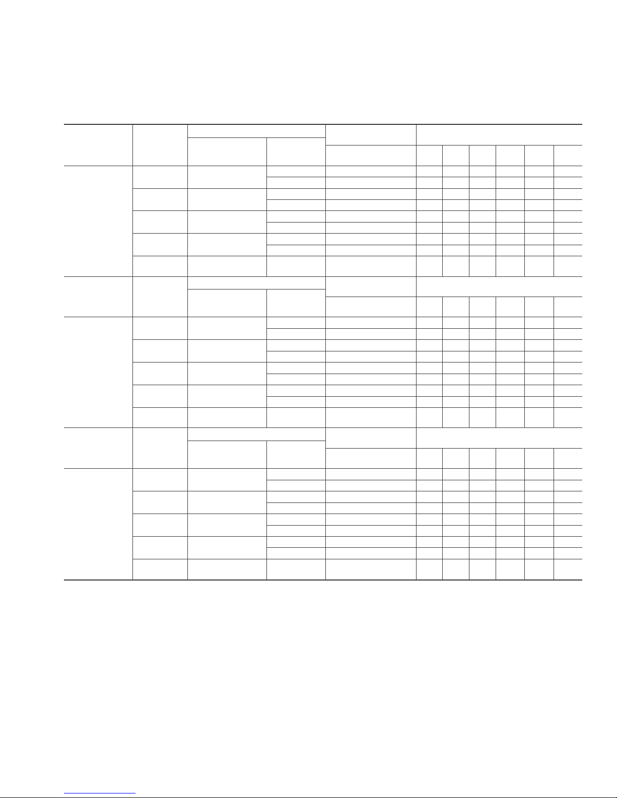
Combustion-air and vent piping for Direct Vent/2-Pipe
(All Sizes) and Non-Direct Vent/1-Pipe (Sizes 040
through 120 Only) Applications
Maximum Allowable Pipe Length (Ft) Continued
NON-DIRECT VENT
(1-PIPE) ONLY
Pipe Dia
(IN.)*
NON-DIRECT VENT
(1-PIPE) ONLY
Pipe Dia
(IN.)*
NON-DIRECT VENT
(1-PIPE) ONLY
Pipe Dia
(IN.)*
NUMBER OF 90° ELBOWS
123 456
NUMBER OF 90° ELBOWS
123 456
NUMBER OF 90° ELBOWS
123 456
3 41 40 38
ALTITUDE
5001 to 6000‡
ALTITUDE
6001 to 7000‡
ALTITUDE
7001 to 8000‡
See notes on page 17.
UNIT SIZE
(BTUH)
40,000
60,000
80,000
100,000
120,000
UNIT SIZE
(BTUH)
40,000
60,000
80,000
100,000
120,000
UNIT SIZE
(BTUH)
40,000
60,000
80,000
100,000
120,000
DIRECT VENT (2-PIPE) ONLY
Termination
Type
2 Pipe or 2-In.
Concentric
2 Pipe or 2-In.
Concentric
2Pipeor2-In.
Concentric
2Pipeor2-In.
Concentric
2 Pipe or 3-In.
Concentric
DIRECT VENT (2-PIPE) ONLY
Termination
Type
2 Pipe or 2-In.
Concentric
2 Pipe or 2-In.
Concentric
2 Pipe or 2-In.
Concentric
2Pipeor2-In.
Concentric
2Pipeor3-In.
Concentric
DIRECT VENT (2-PIPE) ONLY
Termination
Type
2Pipeor2-In.
Concentric
2 Pipe or 2-In.
Concentric
2 Pipe or 2-In.
Concentric
2 Pipe or 2-In.
Concentric
2Pipeor3-In.
Concentric
Pipe Dia
(IN.)*
1-1/2 1-1/2 37 3227 22 17 12
1-1/2 1-1/2 37 3227 22 17 12
1-1/2 1-1/2 22 17 12 7 NA NA
2-1/2 2-1/2 70 70 70 70 70 70
Pipe Dia
(IN.)*
1-1/2 1-1/2 35 3025 20 15 10
1-1/2 1-1/2 35 3025 20 15 10
1-1/2 1-1/2 20 15 10 5 NA NA
2-1/2 2-1/2 70 70 68 67 66 64
Pipe Dia
(IN.)*
1-1/2 1-1/2 322722 17 12 7
1-1/2 1-1/2 322722 17 12 7
1-1/2 1-1/2 18 138NA NA NA
2-1/2 2-1/2 66 65 63 62 60 59
2 2 70 70 70 70 70 70
2 2 70 70 70 70 70 70
2 2 70 70 70 70 68 63
2233 28 23 18 138
3† 3 53 52 50 49 48 47
2 2 70 70 68 67 66 64
2 2 70 70 68 67 66 64
2 2 70 70 68 67 62 57
22312621 16 11 6
3† 3 49 48 47 45 44 43
2 2 66 65 63 62 60 59
2 2 66 65 63 62 60 59
2 2 66 65 63 62 57 52
2 2 29 24 19 14 9 NA
3† 3 46 44 4
16
Page 17
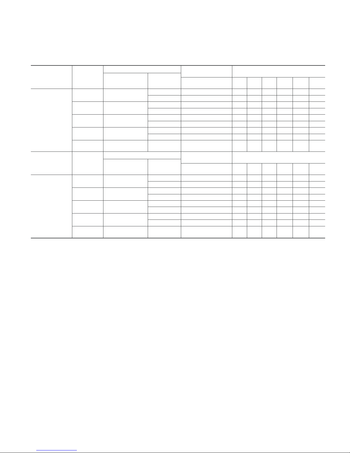
Combustion-air and vent piping for Direct Vent/2-Pipe
(All Sizes) and Non-Direct Vent/1-Pipe (Sizes 040
through 120 Only) Applications
Maximum Allowable Pipe Length (Ft) Continued
ALTITUDE
8001 to 9000‡
ALTITUDE
9001 to 10000‡
* Disk usage—Unless otherwise stated, use perforated disk assembly (factory-supplied in loosepartsbag).
† Wide radius elbow.
‡Ventsizing for Canadianinstallations over 4500 ft (1370m) above sea level are subject to acceptance bythelocal authorities having jurisdiction.
NA—Not Allowed; pressure switch will not make.
NOTES:
1. Do not use pipe size gre
2. Size both the combustion-air and vent pipe independently, determine the smallestdiameter allowed bythetable for each pipe, then usethelarger diameter for both
pipes.
3.Assume two 45° elbows equal one 90° elbow. Long radius elbowsare desirable and may berequ
4. Elbowsand pipe sections within the furnace casing and at the vent termination should not beincluded in vent length or elbow count.
5. The minimum pipe length is 5ftforall applications.
UNIT SIZE
(BTUH)
40,000
60,000
80,000
100,000
120,000
UNIT SIZE
(BTUH)
40,000
60,000
80,000
100,000
120,000
ater thanthose specified in table or incomplete combustion, flame disturbance, or flame senselockoutmay occur.
DIRECT VENT (2-PIPE) ONLY
Termination
Type
2 Pipe or 2-In.
Concentric
2 Pipe or 2-In.
Concentric
2 Pipe or 2-In.
Concentric
2 Pipe or 2-In.
Concentric
2Pipeor3-In.
Concentric
DIRECT VENT (2-PIPE) ONLY
Termination
Type
2 Pipe or 2-In.
Concentric
2 Pipe or 2-In.
Concentric
2 Pipe or 2-In.
Concentric
2 Pipe or 2-In.
Concentric
2Pipeor3-In.
Concentric
Pipe Dia
(IN.)*
1-1/2 1-1/2 302520 15 10 5
2 2 62 60 58 56 55 53
1-1/2 1-1/2 302520 15 10 5
2 2 62 60 58 56 55 53
1-1/2 1-1/2 17 12 7 NA NA NA
2 2 62 60 58 56 51 46
2 2 27 22 17 12 7 NA
2-1/2 2-1/2 62 60 58 56 55 53
3† 3 43 41 39 37 35 34
Pipe Dia
(IN.)*
1-1/2 1-1/2 27 22 17 12 7 NA
2 2 57 55 53 51 49 47
1-1/2 1-1/2 27 22 17 12 7 NA
2 2 57 55 5
1-1/2 1-1/2 15 10 5 NA NA NA
2 2 57 55 53 51 46 41
2 2 24 19 14 9 NA NA
2-1/2 2-1/2 57 55 53 51 49 47
3† 339 37 35 33 3129
NON-DIRECT VENT
(1-PIPE) ONLY
Pipe Dia
(IN.)*
NON-DIRECT VENT
(1-PIPE) ONLY
Pipe Dia
(IN.)*
ired in some cases.
NUMBER OF 90° ELBOWS
123 456
NUMBER OF 90° ELBOWS
123 456
3 51 49 47
17
Page 18
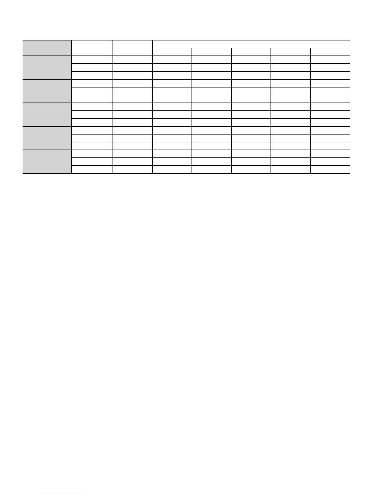
MAXIMUM ALLOWABLE EXPOSED VENT PIPE LENGTH (FT)
WITH INSULATION IN WINTER DESIGN TEMPERATURE AMBIENT*
UNIT SIZE
040-14
060-14
080-14
080-20
100-20
120-20
WINTER DESIGN
TEMP °F
20 2 2137425057
0 2 10 22 25 30 35
- 20 2 5 14 17 21 25
20 2 3055617070
0 2 16 33 38 46 53
- 20 2 9 23 26 33 38
20 2 3765707070
0 2 20 39 45 55 63
- 20 2 11 27 31 39 45
20 2-1/2 41 70 70 70 70
0 2-1/2 21 42 48 59 68
- 20 2-1/2 11 28 33 41 49
20 3 4970707070
0 3 26 51 58 70 70
- 20 3 1535405059
MAX PIPE DIA
(IN.)
0 3/8 1/2 3/4 1
INSULATION THICKNESS (IN.)†
* Pipe length (ft) specified for maximum vent pipe lengths located in unconditioned spaces. Vent pipes located in unconditioned space cannot
exceed the total allowable pipe length as specified in the Maximum Allowable Pipe Length table.
† Insulation thickness based on R value of 3.5 per in.
18
Page 19
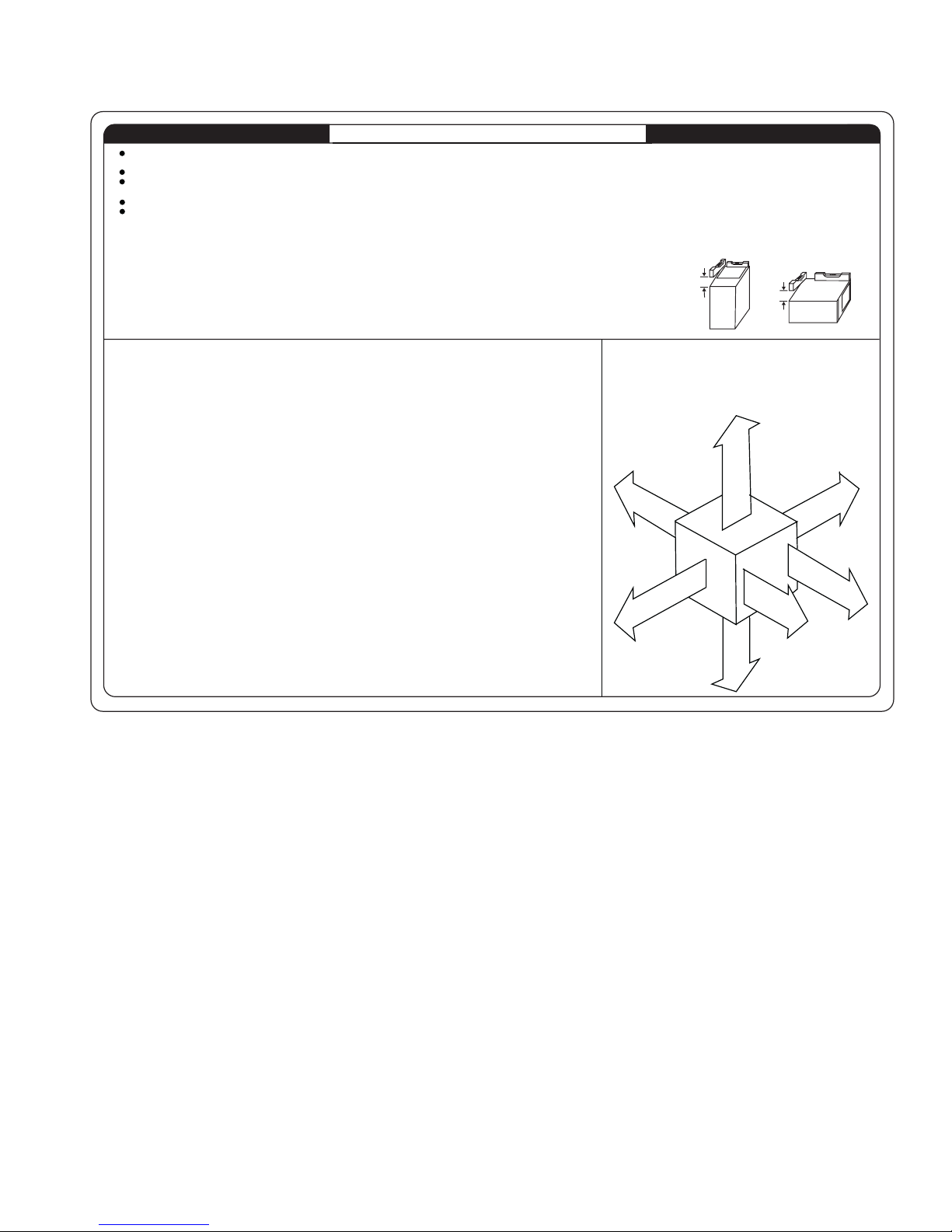
Clearance to combustibles
INSTALLATION
This forced air fur nace is equi pped for use with natur al gas at altitudes 0 - 10, 000 ft (0 - 3,050m), except 140 size fur naces are only approved for altitudes 0 - 7,000 ft.
(0 - 2,135m).
An accessor y kit, supplied by the manufacturer , shall be used to convert to propane gas use or may be requi red for some n atural gas applications.
This furnace is for indoor install ation i n a buildi ng construct ed on site. This fur nace may be install ed in a manufact ured (mobi le) home when st ated on rating plate and
using factory authori zed kit.
This f urnace may be i nstalled on combustible flooring in alcove or cl oset at
This furnace requires a special vent ing system. Refer to the i nstallat ion instr uctions f or parts list and method of i nstallat ion. This furnace is f or use with schedule-40 PVC,
PVC-DWV, CPVC, or ABS-DWV pipe, and must not be vented in common with other gas-fired appliances. Construction through which vent/air intake pi pes may be
installed is maximum 24 i nches (600 mm), minimum 3/ 4 inches (19 mm) thickness (includi ng roofing materi als).
Minimum Inches Clearance To Combustible Construction
as described below.
For upf low and downflow appl ications, furnace must be inst alled level , or pi tched withi n 1/2" of level. For a
horizont al appli cation, the furnace must be pitched mini mum 1/4" to maximum of 1/ 2" forward for proper
drainage. See Instal lat ion Manual f or IMPORTANT unit support details on hori zontal appli cati ons.
MINIMUM INCHES CLEARANCE TO COMBUSTIBLE CONSTRUCTION
ALL POSITIONS:
Mimimum front clearance for servi ce 30 inches (762mm).
*
DOWNFLOW POSITIONS:
For installation on combustible floors only when installed on special base No.
†
KGASB0201ALL, Coil Assembly, Part No. CD5 or CK5, or Coil Casing, Part No. KCAKC.
HORIZONTAL POSITIONS:
Line contact is permissible only between lines formed by intersections of top and two sides
of fur nace jacket, and building joists, studs, or f raming.
§
Clearance shown is for air inlet and ai r out let ends.
120 size furnace requi res 1 inch bot tom cl earance to combustible materials.
Ø
M
328068-201 REV. A
LIT - TOP
LEVEL (0")
UPFLOW OR
DOWNFLOW
This f urnace is approved for UPFLOW, DOWNFLOW and
HORIZONTAL instal lat ion s.
Clearance arrows
do not change with
furnace orientati on.
0"
B
0"
§
Clearance in inches.
1/2" MAX
A
C
K
D
I
S
TO
FRONT
MIN 1/4" TO 1/2" MAX
FRONT
HORIZONTAL
1"
TOP/PLENU
E
C
A
N
R
U
F
N
O
R
F
E
F
R
O
N
BOTTOM
0"
Ø
†
D
I
S
T
S
E
R
V
T
3"
Vent clearance to
combusti bles 0" .
E
I
§
0"
C
E
*
30
MIN
A02250
19
Page 20
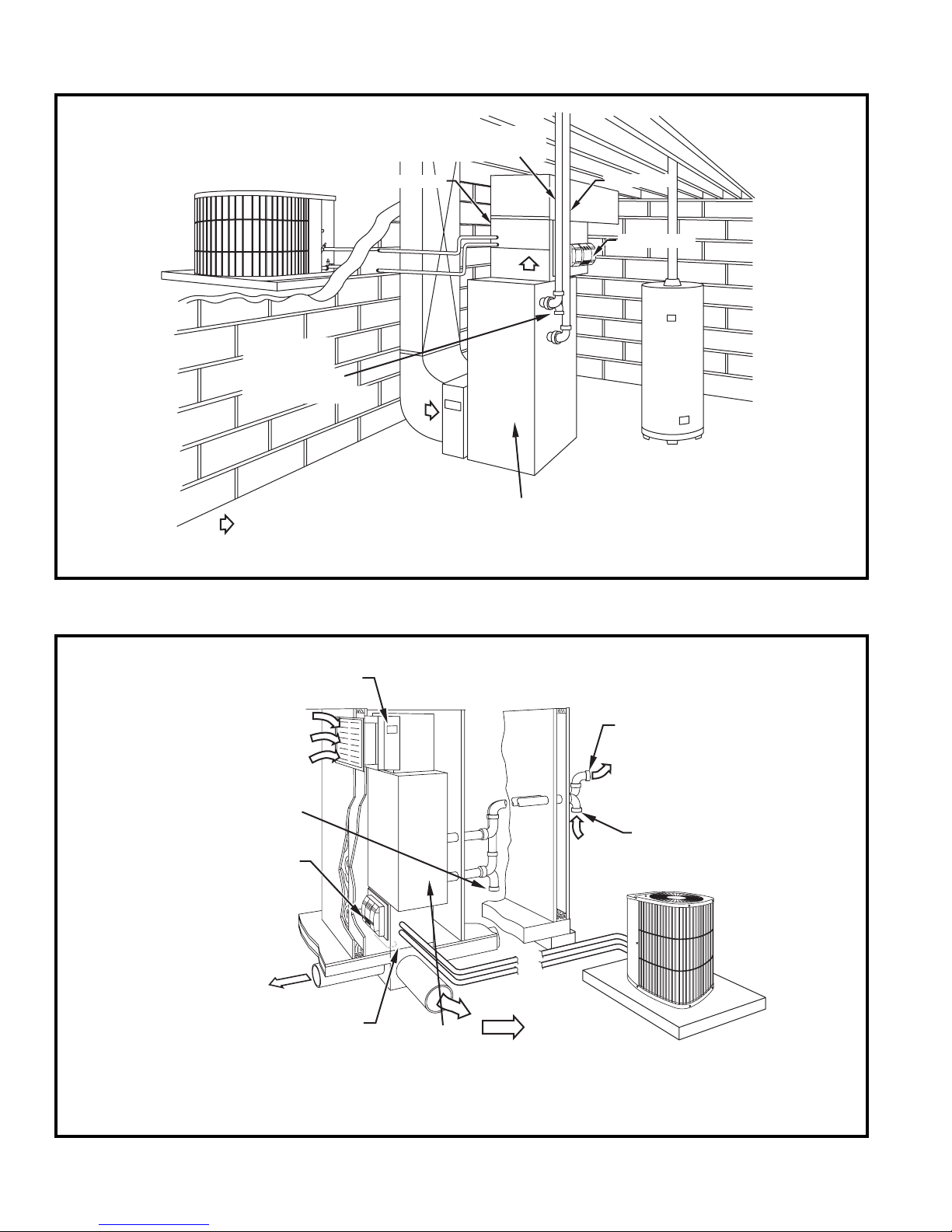
Typical installations
COMBUSTION AIR PIPE
(DIRECT VENT/2-PIPE APPLICATION)
OUTDOOR UNIT
COMBUSTION
AIR INLET
(NON-DIRECT
1-PIPE APPLICATION)
A/C COIL
ELECTRONIC
AIR CLEANER
VENT PIPE
HUMIDIFIER
GAS-FIRED
WATER HEATER
AIRFLOW
ELECTRONIC
AIR CLEANER
COMBUSTION AIR
INLET (NON-DIRECT
VENT/ 1-PIPE APPLICATION
HUMIDIFIER
FRONT OF
FURNACE
A05064
Basement — Upflow Application A05064
VENT
COMBUSTION
AIR (DIRECT VENT/
2 PIPE APPLICATION
OUTDOOR
UNIT
A/C COIL
20
FRONT OF
AIRFLOW
FURNACE
A05065
Closet — Downflow Application A05065
Page 21
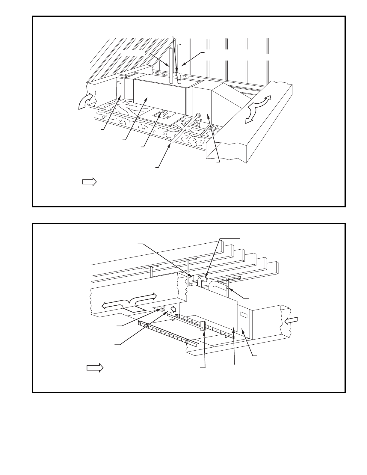
COMBUSTION-AIR INLET
(NON-DIRECT VENT/1-PIPE APPLICATION)
ELECTRONIC
AIR CLEANER
FRONT OF FURNACE
AIRFLOW
VENT PIPE
FURNACE
CONDENSATE
DRAIN
REFRIGERATION
PIPING
COMBUSTION–AIR PIPE
DIRECT VENT/2-PIPE APPLICATION)
AIR CONDITIONING
COIL
A05066
Attic — Horizontal Application A05066
COMBUSTION - AIR INLET
(NON-DIRECT VENT/
1-PIPE APPLICATION)
REFRIGERATION
AIR CONDITIONING
PIPING
COIL
AIRFLOW
COMBUSTION– AIR PIPE
(DIRECT VENT/2-PIPE
APPLICATION)
VENT
PIPE
ELECTRONIC
AIR CLEANER
FURNACE CONDENSATE
DRAIN
FRONT OF
FURNACE
A05067
Crawlspace — Horizontal Application A05067
21
Page 22

22
Page 23

23
Page 24

Copyright 2005 Carrier Corporation • Indianapolis, IN 46231 9-05
Manufacturer reserves the right to discontinue, or change at any time, specifications or designs without notice and without incurring obligations.
Book 1 4 Page 24 Printed in U.S.A. PC 101 Catalog No. 58MVB-1PD
Tab 6a 8a
Replaces: 58MVP-11PD
 Loading...