

Page 1
HORIZONTAL INDUCED-COMBUSTION 58EFB
GAS FURNACE
USER’S INFORMATION MANUAL FOR THE OPERATION
AND MAINTENANCE OF YOUR NEW GAS-FIRED FURNACE
a
WARNING: If the information in this manual
is not followed exactly, a fire or explosion may
result causing property damage, personal injury or loss of life.
— Do not store or use gasoline or other flam-
mable vapors and liquids in the vicinity of
this or any other appliance.
— WHAT TO DO IF YOU SMELL GAS:
• Do not try to light any appliance.
• Do not touch any electrical switch; do not
use any phone in your building.
• Immediately call your gas supplier from a
neighbor’s phone. Follow the gas supplier’s
instructions.
• If you cannot reach your gas supplier, call the
fire department.
ON
OFF
NOTE TO INSTALLER:
THIS MANUAL MUST BE
LEFT WITH THE
EQUIPMENT USER.
— Installation and service must be performed
by a qualified installer, service agency
or the gas supplier.
Page 2
WELCOME TO A NEW GENERATION
OF COMFORT
Congratulations! Y our ne w 80%* efficient gas furnace is a sound
investment which will re ward you and your f amily with years of
“warm memories” winter after winter.
Not only is your new furnace energy efficient, it is also one of
the most reliable. Spend just a few minutes with this booklet to
learn about the operation of your new furnace—and the small
amount of maintenance it takes to keep it operating at peak ef ficiency. Years went into the development of your new furnace.
Take a little time now to assure its most efficient operation for
years to come.
* The output capacity and any representations of efficiency for this furnace are based on standard Depart-
ment of Energy test procedures.
INSTALLATION DATA
Date Installed
Dealer Name
Address
City
State Zip
Telephone
ON
OFF
MODEL 58EFB HORIZONTAL FURNACE
OUTDOOR UNIT:
Product No.
Model No.
Serial No.
INDOOR COIL:
1
SPLIT-SYSTEM
FURNACE
Product No.
Model No.
Serial No.
Product No.
Model No.
Serial No.
2
Page 3
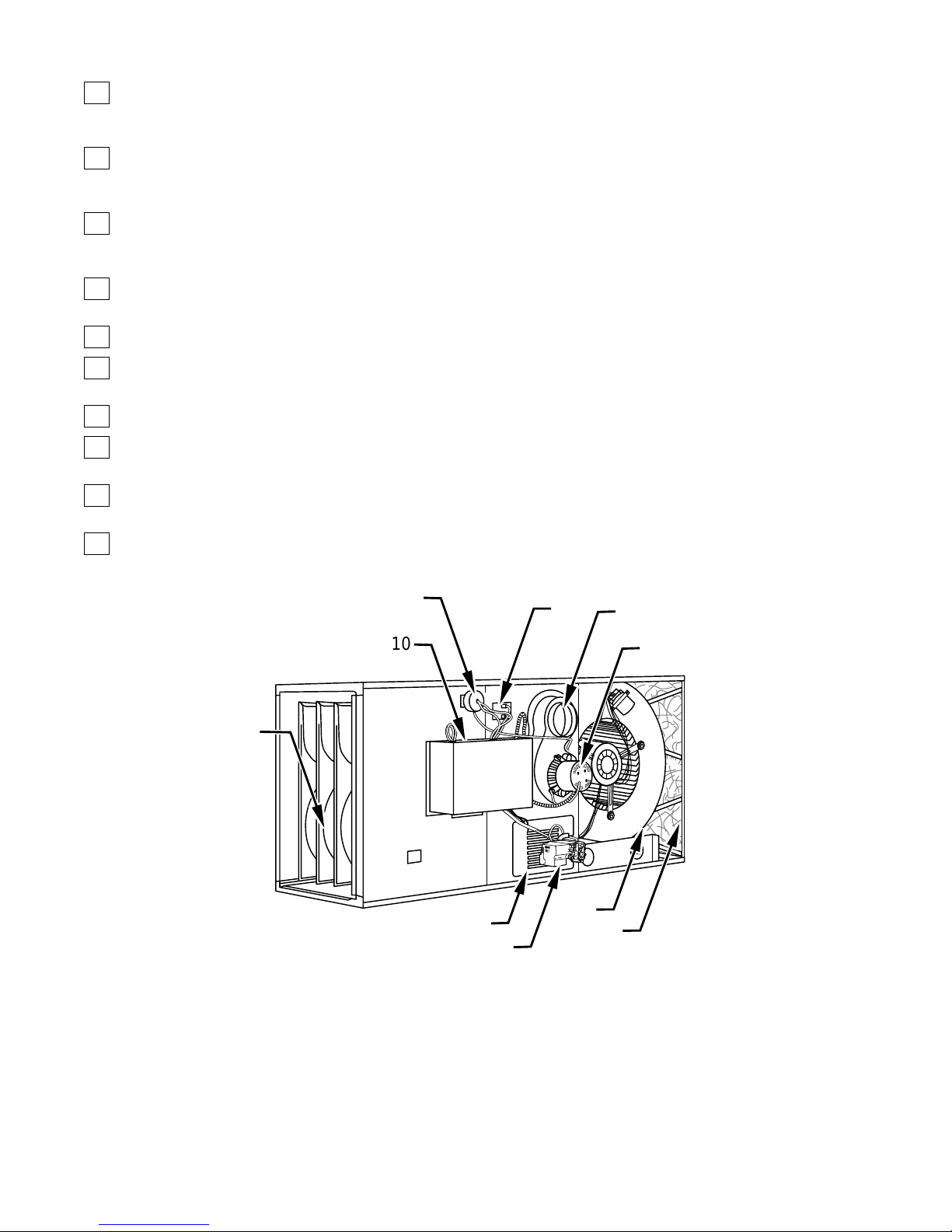
HORIZONTAL FURNACE COMPONENTS
1
Primary serpentine heat exchanger. Stretches fuel dollars
with the S-shaped heat flow design. Solid construction of
corrosion-resistant aluminized steel means reliability.
2
Burner assembly (inside). Operates with energy-saving
pilot, inshot burners, and hot surface igniter for safe,
dependable heating.
3
Gas valve — ignition module assembly. Safe, efficient.
Features 2 separate gas shutoff valves and integrated ignition control.
4
Heavy-duty blower. Circulates air, scrubbing the heat exchangers to transfer heat into the home.
5
Air filter and wire filter retainer (optional).
6
Inducer motor. Pulls hot flue gases through the heat exchangers, maintaining negative pressure for added safety.
7
Vent outlet. Carries vent gases from the home.
8
Limit switch. Shuts furnace down in the event of an overheating condition.
9
Pressure switch. Ensures adequate flow of flue products
through furnace and out vent system.
10
Control center.
1
10
9
8
7
6
ON
OFF
4
2
5
3
2
MODEL 58EFB HORIZONTAL FURNACE
(Unit Shown In Horizontal Left Configuration)
3
Page 4
5
IMPORTANT FACTS
Your furnace must have adequate airflow for efficient combustion and safe ventilation. Do not enclose it in an airtight room or
“seal” it behind solid doors.
ON
OFF
3
T o minimize the possibility of serious personal injury, fire, damage to your furnace, or improper operation,
these safety rules:
•
Keep the area around your furnace free of combustible mate-
rials, gasoline, and other flammable liquids and v apors.
•
Do not cover the furnace, store trash or debris near it, or in an y
way block the flow of fresh air to the unit.
•
A furnace installed in an attic or other insulated space must be
kept free and clear of insulating material. Examine the furnace
area when installing the furnace or adding more insulation.
Some materials may be combustible.
NOTE:
Immediately call a qualified service technician to inspect the fur nace and to replace any part of the control system and any gas
control which has been under water.
Do not use this furnace if any part has been under water.
carefully follow
Untrained personnel can perform basic maintenance functions
such as cleaning and replacing air filters. All other operations
must be performed by trained service personnel. Observe safety
precautions in this manual, on tags, and on labels attached to the
furnace and other safety precautions that may apply.
Recognize safety information. This is the safety-alert symbol
!
. When you see this symbol on the furnace and in instructions
or manuals, be alert to the potential for personal injury.
Understand the signal words D ANGER, WARNING, and CA U-
TION. These words are used with the safety-alert symbol. D ANGER identifies the most serious hazards which
severe personal injury or death. WARNING signifies hazards
which
could
result in personal injury or death. CAUTION is
used to identify unsafe practices which
personal injury or product and property damage.
would
will
result in
result in minor
ST ARTING YOUR FURNACE
Instead of a continuously burning pilot flame which w astes valuable energy , your furnace uses an automatic, hot surf ace ignition
system to light the pilot each time the thermostat starts your fur nace.
Follow these important safeguards:
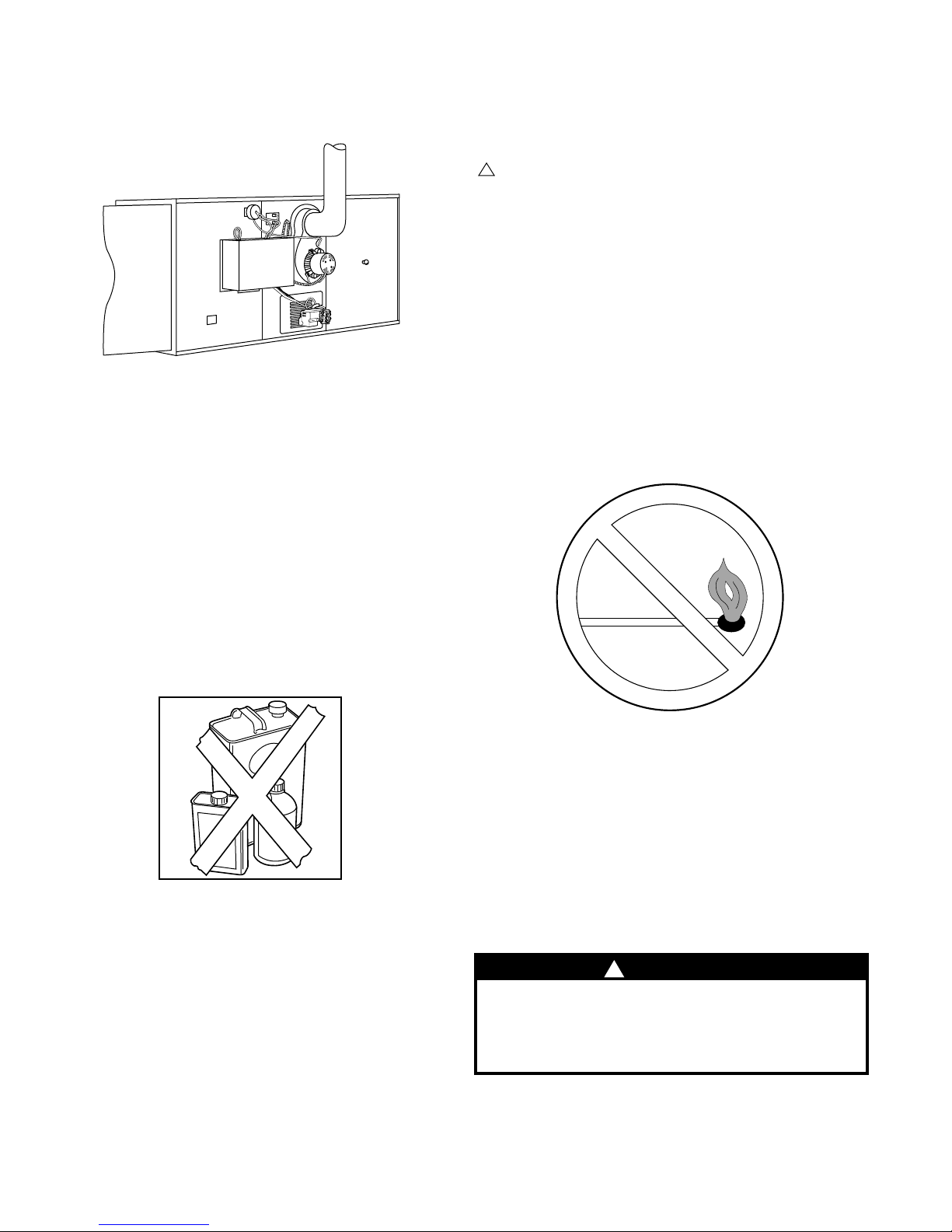
•
Never attempt to light the pilot manually with a match or
other source of flame.
NOTE:
authorized replacement parts, kits, and accessories when modifying this product.
If the furnace is left unattended for an extended period of time,
have it checked periodically for proper operation. This precaution will prevent problems associated with NO HEAT, such as
frozen water pipes, etc. See “Before You Request a Service Call”
section in this manual.
The qualified installer or agency must use only f actory-
SAFETY CONSIDERATIONS
Installing and servicing of heating equipment can be hazardous
due to gas and electrical components. Only trained and qualified
personnel should install, repair, or service heating equipment.
•
Read and follow the operating instructions on the furnace, es-
pecially the item that reads as follows:
Wait 5 minutes to clear out any gas. Then smell for gas, including near the floor . If you smell gas,
the safety information above on this furnace label. If you don’ t
smell gas, go to the next step.
•
If a suspected malfunction occurs with your gas control sys-
tem, such as the burners not lighting when the y should, refer to
4
the shutdown procedures on the furnace or in the ne xt section to
turn off your system, then call your dealer as soon as possible.
!
WARNING
If overheating occurs, or the gas valve fails to shut
off the gas supply, turn off the manual gas valve (see
Fig. 7) to the furnace BEFORE turning off the electrical supply. Failure to follow this warning could result
in a fire or explosion, and personal injury or death.
CHECK AIR FILTER:
•
nace, be sure the furnace filter is clean and in place. (See the
maintenance section of this manual.) Then proceed as follows:
4
Before attempting to start your fur-
STOP!
Follow “B” in
Page 5
STEPS FOR STARTING YOUR FURNACE
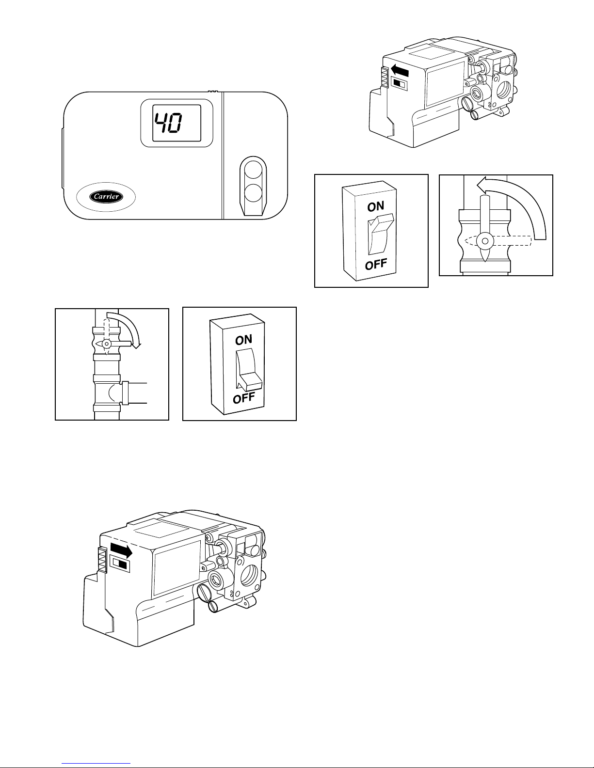
1. Set your room thermostat to the lowest temperature setting.
(See Fig. 6.)
5
®
2. Close the external manual gas valve. (See Fig. 7.)
3. Turn off the electrical supply to the furnace. (See Fig. 8.)
C
L
O
S
E
78
4. Turn the switch on the gas valve to the OFF position and
wait 5 minutes. (See Fig. 9.)
ON
OFF
ON
OFF
6
11 12
8. Set the room thermostat to a temperature slightly above room
temperature. This will automatically signal the furnace to
start. The inducer motor will start, the pressure switch will
close, and the hot surface igniter will be energized.
9. The hot surface igniter will light the pilot flame. Once the
pilot flame is sensed, the gas valv e permits gas to flow to the
main burners where it is ignited. Hot flames be gin to w arm
the furnace’s heat exchanger. After a time delay of approximately 30 sec, the furnace blower is switched on.
If the pilot fails to light, the ignitor remains energized, and pilot
gas valve remains open. If this is due to a gas interruption, the
system continues its attempt to light pilot until gas is restored
and unit lights or system is turned off.
10. Set your thermostat to the temperature that satisfies your
comfort requirements. SUGGESTION: Setting the thermostat back a few degrees and compensating for the dif ference
with warmer clothing can make a big dif ference in your fuel
consumption on extremely cold days. The few degrees at
the top of your thermostat “comfort level” are the most
costly degrees to obtain.
When room temperature drops below the temperature selected on the thermostat, the furnace will be switched on
automatically. When room temperature reaches the degree
selected on the thermostat, the furnace will be switched of f
automatically .
Some thermostats have a f an mode with 2 selections: AUTO
and ON. When set to AUTO, the furnace blower cycles on
and off, controlled by the thermostat. In ON mode, the furnace blower runs continuously except for a 30-sec delay at
the call for heat. This keeps the temperature level in your
home more evenly balanced. It also continuously filters the
indoor air.
O
P
E
10
N
5. After waiting 5 minutes, turn the switch on the gas v alv e to
the ON position. (See Fig. 10.)
6. Turn on the electrical supply to the furnace. (See Fig. 11.)
7. Open the external manual gas valve. (See Fig. 12.)
9
SHUTTING DOWN YOUR FURNACE
Should you ever suspect a malfunction in your furnace, you will
need to turn the furnace off. The following procedures must be
followed:
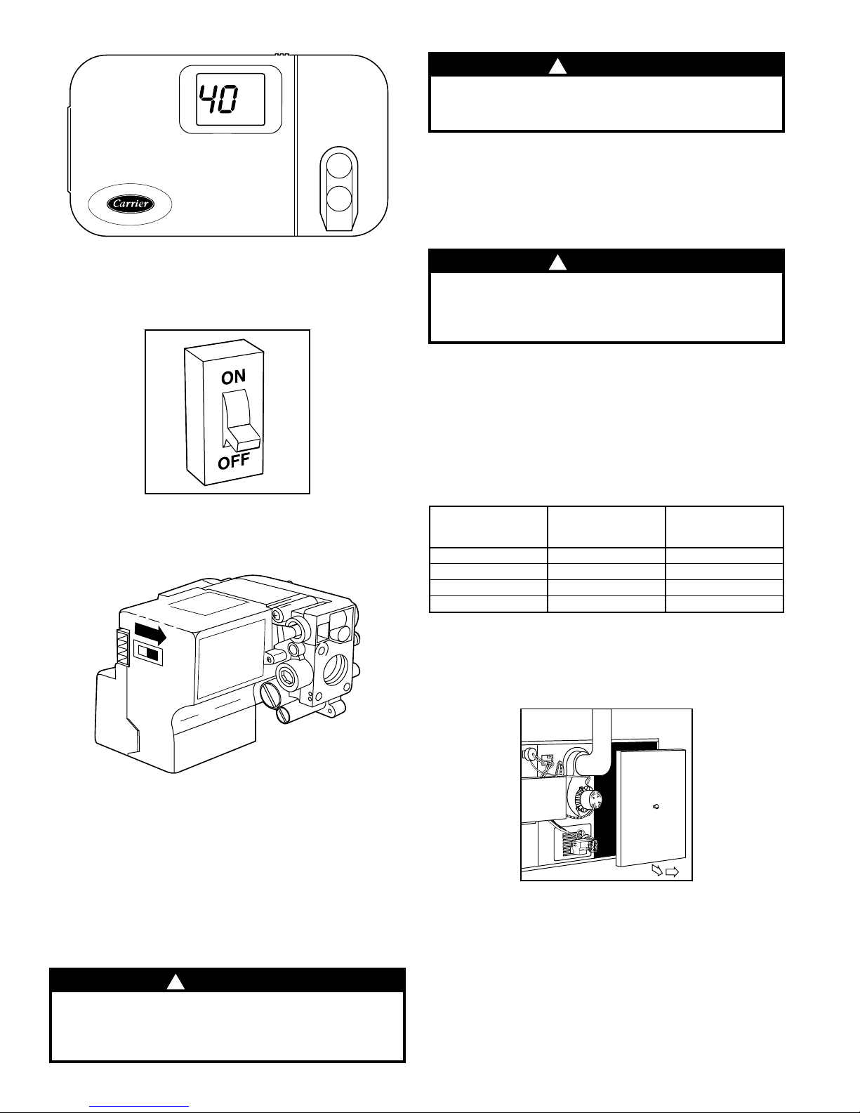
1. Set your room thermostat to the lowest temperature setting.
(See Fig. 13.)
Page 6
!
CAUTION
Although special care has been taken to minimize
sharp edges, be extremely careful when handling
parts or reaching into the furnace.
FILTERING OUT TROUBLE
(Optional Accessory)
A dirty filter will cause excessive stress on the furnace blower
®
motor and can cause it to overheat and automatically shut do wn.
The furnace filter should be checked every 3 or 4 weeks and
cleaned if necessary.
13
2. Close the external manual gas valve. (See Fig. 7.)
3. Turn of f the electrical po wer to your furnace. (See Fig. 14.)
14
4. Turn the switch on the gas valve to the OFF position. (See
Fig. 15.)
ON
OFF
!
CAUTION
Never operate your furnace without a filter in place.
Doing so may damage the furnace blower motor. An
accumulation of dust and lint on internal parts of
your furnace can cause a loss of efficiency.
The air filter is normally located in the blower compartment before the blower (See Fig. 17.) If the filter(s) has been installed in
another location, contact your dealer for instructions. To inspect,
clean, and/or replace the air filter(s), follow these steps:
If your furnace filter needs to be replaced, be sure to use the same
size and type of filter that was originally supplied. Use the furnace filter table and compare your furnace size with the proper
filter size.
HORIZONTAL FURNACE FIL TER TABLE
HORIZONTAL
FURNACE INPUT
(BTUH)
50,000 (1) 13 x 23 x 1/2 Cleanable
75,000 (1) 13 x 23 x 1/2 Cleanable
100,000 (1) 16-1/2 x 23 x 1/2 Cleanable
125,000 (1) 20 x 23 x 1/2 Cleanable
•
REMOVE THE FILTER FOR CLEANING AS FOLLOWS:
FILTER
SIZE
(IN.)
FILTER
TYPE
1. Turn off electrical supply to the furnace. (See Fig. 14.)
2. Remove blo wer access door located at the inlet (return-air)
end of the furnace (4 screws must be remo ved).
(See Fig. 16.)
5. If the furnace is being shut down because of a malfunction,
call your dealer as soon as possible.
PERFORMING ROUTINE MAINTENANCE
With proper maintenance and care, your furnace will operate
economically and dependably. Instructions for basic maintenance are found on this and the following pages. However, before beginning maintenance, follo w these safety precautions:
!
WARNING
Turn off electrical power supply to your furnace before removing the access doors to service or perform
maintenance. Failure to follow this warning could result in personal injury or death.
15
ON
OFF
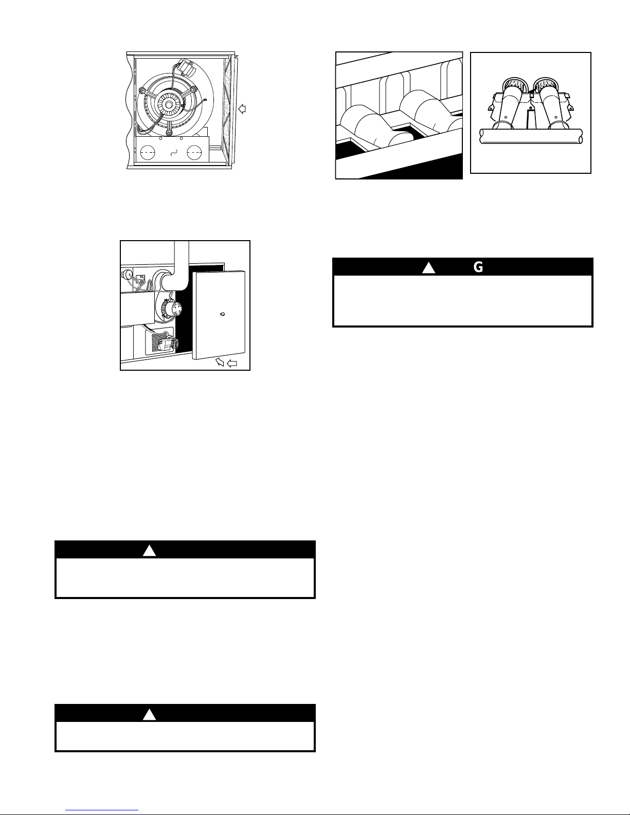
3. Bend the formed wire filter retainer to clear the furnace
flange at 1 side.
4. Pivot the filter retainer toward the blower. (See Fig. 17.)
5. Remove the filter from the furnace.
6. Inspect the fi lter. If torn, replace it.
7. Wash the filter (if dirty) in a sink, bathtub, or outside with a
garden hose. Always use cold tap water. A mild liquid detergent may be used if necessary. Spray water through the
filter in the opposite direction of airflow through the crossmesh binding side. Allow filter to dry.
6
16
Page 7
17
8. Reinstall the clean filter with the cross-mesh binding side
facing the furnace blower.
9. Replace blower door, reinstall 4 screws (see Fig. 18), and
turn on electrical power to your furnace.
7
19 20
3. Inspect the vent pipe for sags, holes, cracks, or disconnections. Any horizontal vent pipe must slope upward, away
from the furnace. If rusty joints or seams, or signs of water
leakage are found, call your dealer for service.
!
DANGER
If holes are found in the vent pipe, or if it has become
disconnected, toxic fumes can escape into your
home. DO NOT OPERATE YOUR FURNACE. Call
your dealer for service.
ON
OFF
18
COMBUSTION AREA AND VENT SYSTEM
Visually inspect the combustion area and vent system before
each heating season. Make sure that the pipe leading into the
vent is free from any cracks and sags. Also check the vent pipe
on the outside of your home for blockage.
When dirt, soot, or rust is allowed to b uild up, your furnace can
suffer a loss of efficiency and perform improperly. Accumulations on the main burners can result in their firing out of normal
sequence. This delayed ignition will create an alarmingly loud
sound.
!
CAUTION
If your furnace makes an especially loud noise when
the main burners light, shut down your furnace and
call your dealer.
To inspect the combustion area and vent system, you will need
a flashlight. Refer to Fig. 2 and proceed as follows:
1. Turn of f the electrical supply to your furnace. (See Fig. 14.)
2. Remove b urner enclosure front.
Inspect the gas burners for dirt, rust, soot, or scale. (See Fig. 19.)
Then inspect the vent outlet area and vent pipe.
!
CAUTION
If dirt, rust, soot, or scale accumulations are found,
call your dealer. Do not operate your furnace.
4. Reinstall the burner enclosure front.
5. If your furnace is free of the above conditions, restore electrical power to your furnace. (See Fig. 11.)
6. Start your furnace and observe its operation. Watch the
burner flames to see if they are clear blue, almost transparent. (See Fig. 20.) If you observe a suspected malfunction,
or the burner flames are not clear blue, call your dealer.
A CHECK-UP CHECKLIST
Your furnace represents an important investment in your family’s comfort and your home’ s v alue. T o k eep it in tip-top shape
and as a preventati ve to future problems, ha ve a trained service
specialist give your furnace a professional check-up annually.
The following checklist can be used as a guideline to proper
service:
•
Inspect all flue gas passages, burners, heat exchangers, and
inducer assembly.
•
Inspect all combustion and ventilation air passages and open-
ings, including vent pipe terminations outside the structure.
•
Check gas pipes leading to and inside of your furnace for
leaks.
•
Inspect, clean, and lubricate the blower motor and wheel as
required.
NOTE:
Maintenance Instructions for blower motor oiling information.
The motor must be oiled by a qualified service technician.
•
•
leaks, and insulation. Remedy any problem when necessary.
•
loose connections.
•
furnace is working properly and if it requires adjustments.
If oil ports are provided, refer to the unit Service and
Inspect and change or clean air filter(s) if necessary.
Inspect all supply- and return-air ducts for obstructions, air
Inspect electrical wiring, connections, and components for
Perform an operational checkout to determine whether your
Page 8

•
Examine the physical support of the furnace; the support
should be sound with no cracks, sagging, gaps, etc. around the
base.
•
Check the furnace for any obvious signs of deterioration.
• Your servicing dealer offers an economical service agreement
that covers seasonal inspections; ask for details.
BEFORE YOU REQUEST A SERVICE CALL
If your furnace is not operating or not performing properly, you
may save the expense of a service call by checking a few things
yourself before calling for service.
FOR INSUFFICIENT AIRFLOW:
• Check for dirty air filter(s).
• Check for blocked return-air or supply-air grilles throughout
your home; ensure they are open and unobstructed.
If problem still exists, call your dealer for service.
IF FURNACE FAILS TO OPERATE:
Follow this checklist step by step, advancing to the next 1 only
if furnace fails to start.
• Check thermostat for proper temperature (set above room
temperature).
• Is the thermostat set on HEAT?
• Check fuses and circuit breakers. Is electrical supply on?
• Is the manual shutoff valve in gas supply pipe in open posi-
tion? (Follow start-up procedures if you open gas valve.)
NOTE: Turn off the electrical power supply before continuing
with checklist.
• Is the switch on gas valve in ON position? (Follow start-up
procedures if you must reset knob to ON.)
• Check the manual reset flame rollout switch located on the
burner assembly. (See Fig. 2.) If the furnace has experienced
high temperature conditions, this switch will shut off the furnace. Reset it by pushing the button on the switch. If it trips
again, shut down the furnace and call for service. See “Shutting
Down Your Furnace” section in this manual.
• Check for obstructions around the vent termination.
If your furnace still fails to operate, call your service representative.
For your con venience, record the product and serial numbers on
the form on page 2. Should you ever require service, you will
have ready access to the information needed by your service
representative.
TO OBTAIN INFORMATION ON PARTS: Consult your installing dealer or the classified section of your local telephone directory under the
Manufacturer reserves the right to discontinue, or change at any time, specifications or designs without notice and without incurring obligations .
Copyright 1998 Carrier Corporation Form: OM58-89 Replaces: OM58-77 Printed in the U.S.A. a
“Heating Equipment’’ or “Air Conditioning Contractors & Systems’’ heading for dealer listing by brand name.
Have available the Model No., Series Letter, & Serial No. of your equipment to ensure correct replacement part.
Carrier Corporation 7310 West Morris St. Indianapolis, IN 46231
6-98 PC 101 Catalog No. 535-700
 Loading...