

Page 1
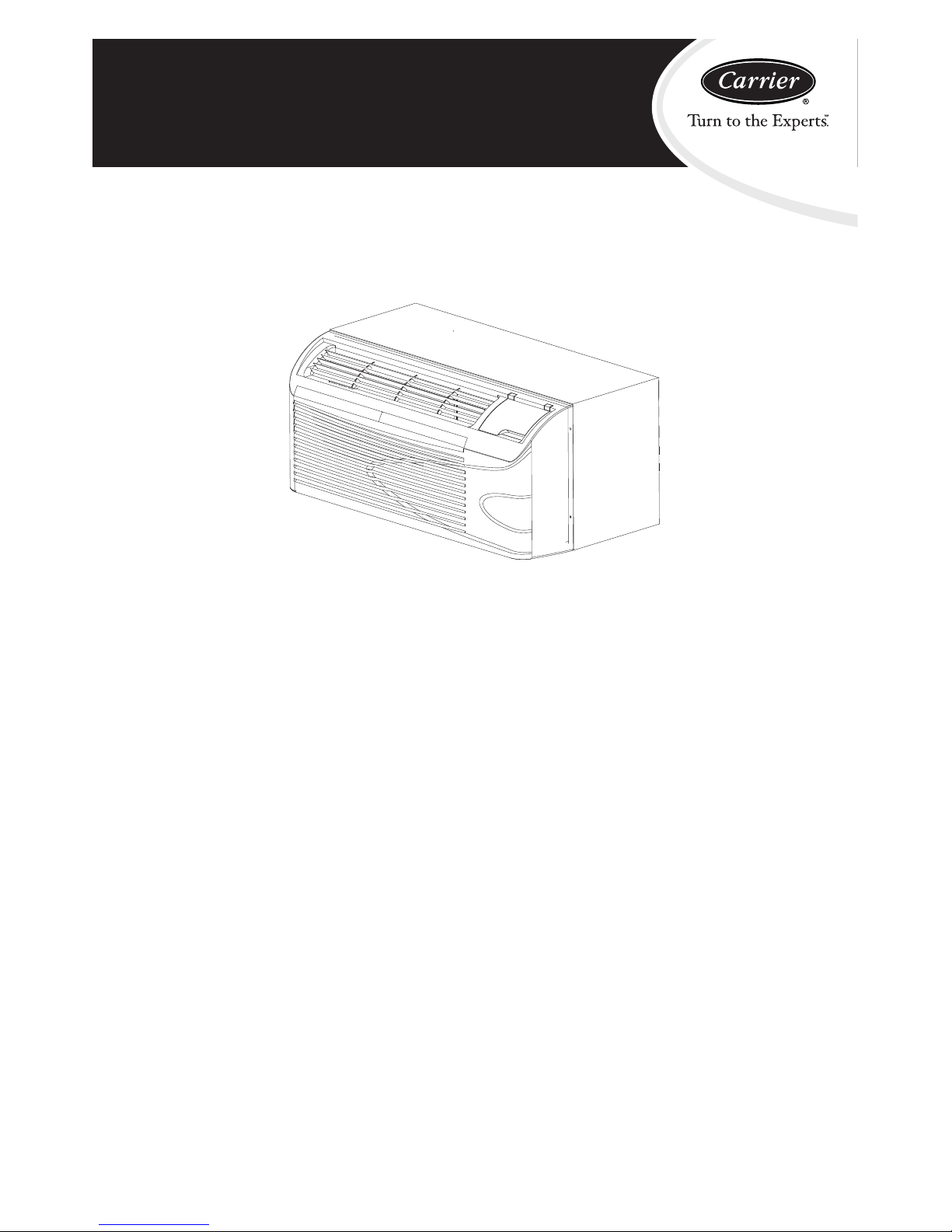
52M Performancet Se r ies
Packaged Terminal Air Conditioner / Heat Pump
7,000 --- 15,000 Btuh
Product Data
TABLE OF CONTENTS
PAGE
QUICK SPECIFICATIONS 3..........................
APPLICATIONS 4--5.................................
New Construction 4................................
Retrofit Replacement 4.............................
Carrier Warranty 4.................................
Application Considerations 5........................
PRODUCT OVERVIEW 6.............................
PRODUCT FEATURES & BENEFITS 7--14..............
Quiet Operation 7.................................
Most Efficient Performance 7........................
Efficient Fan Motor 7...............................
No---Rust Weather Lastt Wall Sleeve & Front Panel 8...
Removable Front Panel 8...........................
Two --- Piece Lifetime Indoor Filter 8...................
Washable Vent Filter 9.............................
Bi---Directional Discharge Grille 9....................
Digital Keypad and Electronic Display 9...............
System Configuration 9............................
Wall Thermostat Interface 9.........................
Energy Management (EM) Interface 10...............
Power Cord for 265V Units 10.......................
Power Cord Protection for 230/208V Units 11..........
A07228
Bi--- Molded Condenser Shroud 11...................
Easy Access Chassis 11............................
Enhanced Copper Tubing 12........................
Seamless Basepan 12.............................
Condensate Drain Valve 12.........................
Condensate Removal 12...........................
Heat Pumps Pay Their Way 13......................
Heat Pump Energy Savings 14......................
ORDERING DATA 15................................
Product Catalog Number 15........................
Required Accessory Power Cord Catalog Number 15...
FIELD INSTALLED ACCESSORIES 16--23..............
DIMENSIONAL DRAWINGS &
INSTALLATION DATA -- NEW CONSTRUCTION 24--28..
WALL THERMOSTAT CONNECTIONS 29..............
PERFORMANCE AND ELECTRICAL DATA 30--33......
TYPICAL WIRING SCHEMATIC
FOR EM INTERFACE 34.............................
TYPICAL WIRING SCHEMATIC FOR MULTIPLE PTAC
UNITS CONNECTED TO A SINGLE WALL TSTAT 35....
GUIDE SPECIFICATIONS 36--39.......................
ACCESSORIES 40...................................
PTAC LIMITED WARRANTY 41.......................
1
Page 2

e
g
52M
Valued Carrier Customer,
Carrier’s Product Data Manual has been specifically developed to make your product and
accessory selection easier and faster than ever. This manual will help you customize your
application to ensure the greatest comfort for your guests and the highest reliability and
lowest costs for you.
Enjoy the ultimate in comfort, humidity control, and energy savings with Carrier’s
complete line of Packaged Terminal Air Conditioning (PTAC) products. The Performanc
series (52M), whisper quiet model, is Carrier's quietest and most energy efficient PTAC
unit ever.
The Performance refrigerant system utilizes the highest efficiency compressors and coil
design to achieve maximum energy efficiency. The airflow system uses two fan motors
and an indoor tangential blower wheel for maximum comfort and superior sound. Choose
the 52M Performance series now and start recovering your investment immediately throu
energy savings, guest satisfaction and enjoy years of economical, trouble-free operation
and comfort.
Thank you for choosing Carrier and investing in the highest quality air conditioning and
heating system ever.
Best regards,
Lodging Products Group
2
Page 3
Ship
y
p
y
p
y
Weig ht lb.
Weig ht lb.
Approx. Ship
Full Amps
Branch Circuit
(Amps)
Current
.
acit
and ca
erformance, efficienc
(Watts)
Input Power
seals of certified
Always look for these symbols, the air conditioning
industr
52M
Indoor CFM COOLING Approx.
--- --- --- --- --- ---
Low Med High AMPS WATTS
Range
Volt age
187 --- 253
--- --- --- --- --- ---
239---292
COP
--- ---
(BTUH)
Reverse
Cycle Heat
Indoor CFM COOLING
Low Med High AMPS WATTS
Range
Volt age
Heater (Kw)
COP
--- --- --- --- --- --- --- --- ---
Heat (BTUH)
Reverse Cycle
pacity
(BTUH)
Electrical
Heating Ca-
Determined
low.
See chart be-
by your power
cord selection.
EER
(BTUH)
Cooling
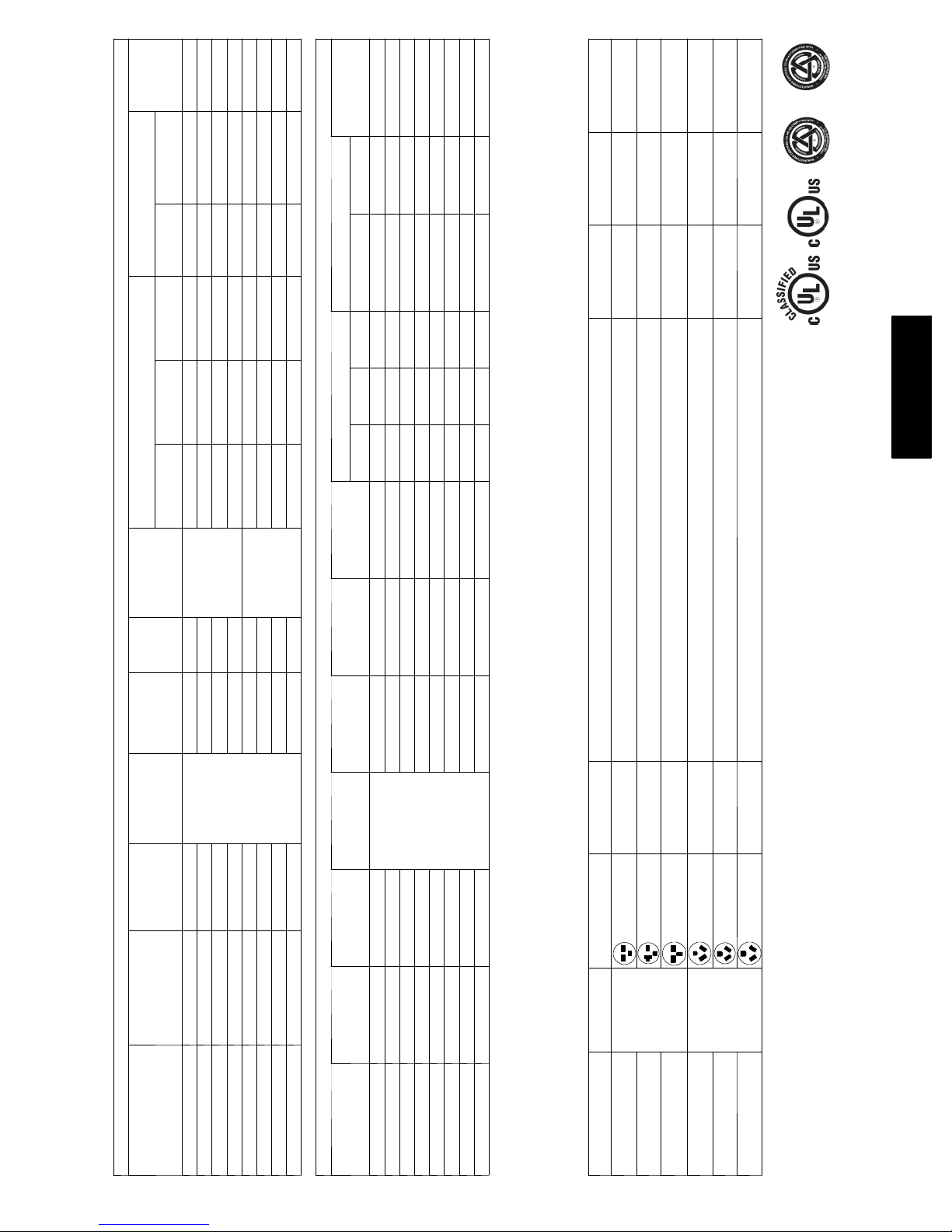
QUICK SPECIFICATIONS
Capacity
MODEL NUMBER
5 2 M E --- U 0 7 --- --- --- 3 --- ---
5 2 M E --- U 0 9 --- --- --- 3 8800 / 9000 11.4 / 11.4 --- --- 265 290 330 3.9 / 3.7 770 / 790 125
5 2 M E --- U 1 2 --- --- --- 3 12,000 / 12,100 11.4 / 11.5 --- --- 280 300 320 5/ 4.7 1060 / 1070 140
5 2 M E --- U 1 5 --- --- --- 3 --- --- --- --- --- --- --- --- --- ---
5 2 M E --- U 0 7 --- --- --- 4 --- --- --- ---
5 2 M E --- U 0 9 --- --- --- 4 9,100 11.7 --- --- 265 300 320 3.3 790 125
5 2 M E --- U 1 2 --- --- --- 4 12,100 11.5 --- --- 280 310 345 4.35 1050 140
COOLING & ELECTRIC HEAT
5 2 M E --- U 1 5 --- --- --- 4 --- --- --- --- --- --- --- --- --- ---
(BTUH)
52M PTACs are not individually equipped with a power cord, so one must be ordered separately based on the voltage and amperage of your electrical circuit. If the
Heating
15 amp /250V 7,800 / 6,400 2.5 2,393 / 1,985 10.4 / 9.5 15
208/230V
Model No. Voltage Receptac le Type
PWRCORD--- 230V---15A
unit i s to be p lugged into a receptacle, then a line cord connection kit needs to be selected. If i t will be permanently connected, a hardwi re connection must be used.
PWRCORD--- 230V---20A 20 AMP / 250V 11,600 / 9,700 3.4 3,493 / 2,935 11.52 / 14.1 20
15 AMP / 277V 7,800 2.5 2,396 9.2 15
265V
PWRCORD--- 230V---30A 30 AMP / 250V 17,000 / 13,600 5.0 5,170 / 4,147 22.5 / 20.0 30
PWRCORD--- 265V---15A
PWRCORD--- 265V---20A 20 AMP / 277V 11,600 3.4 3,496 13.3 20
PWRCORD--- 265V---20A 30 AMP / 277V 17,000 5.0 5,170 19.6 30
NOTE: In compliance with UL, and the National Electrical Code, 265V units installed iwth a power cord require the u se use of a 265V electrical subbase.
Electrical
city (BTUH)
Heating Capa-
your power
See chart be-
Determined by
cord selection.
EER
low.
(BTUH)
Cooling
Capacity
Model No.
5 2 M Q --- U 0 7 --- --- --- 3 --- ---
5 2 M Q --- U 0 9 --- --- --- 3 8,800 / 9,000 10.5 / 10.5 8,300 / 8,350 3.4 / 3.3 187---253 270 320 350 4.1 / 3.9 840 860 125
5 2 M Q --- U 1 2 --- --- --- 3 12,000 / 12,000 11.1 / 11.1 10,700 / 10,900 3.4 / 3.3 187--- 253 280 320 350 5.1 / 4.8 1080 1090 140
5 2 M Q --- U 1 5 --- --- --- 3 --- --- --- --- --- --- --- --- --- --- ---
5 2 M Q --- U 0 7 --- --- --- 4 --- --- --- --- --- --- --- --- --- --- ---
5 2 M Q --- U 0 9 --- --- --- 4 9,000 10.9 8,400 3.5 239---292 275 285 300 3.2 825 125
5 2 M Q --- U 1 2 --- --- --- 4 11,400 10.8 10,600 3 239 --- 292 220 250 290 4.2 1,050 140
HEAT PUMPS
5 2 M Q --- U 1 5 --- --- --- 4 15,000 --- --- --- --- --- --- --- --- --- ---
POWER CORD SELECTION:
3
Page 4

APPLICATIONS
Whether you are desig n i ng a new struct u re or
replacing packaged terminal air conditioning units in
an existing building, C arrier will meet your needs.
S Hotels and motels
S Nursing homes and assisted living care
centers
S Offices
S Apartments
S Single--family dwellings
S Home conversions and residential add--ons
NEW CONSTRUCTION
The Carrier 52 M P ack ag ed Terminal Air
Conditioning (PTAC) unit is designed to meet the
52M
needs of the archit ect , engineer, and contractor. For
unitinstallation,Carrier’sexpertsupport network will
assist in all appli cab l e aspects of t h e con s t ruct i o n
project, from preparing a budget to start--up.
ADVANTAGES FOR NEW
CONSTRUCTION
Design Flexibility for the Architect/Engineer
S Whisper--quiet performance, indoors and out
S No bulky duct system
S No separate equipment room
S No water towers or additional cooling
equipment
S No complex match--up of different HVAC
components
S Less sensitivity to building orientation (sun,
wind, shade)
S Optional architectural grille to permit custom
exterior appearance
Initial Cost Savings for the Building Owner
S No expensive component HVAC system
purchase
S No equipment room or maintenance
engineering staff
S Two--part delivery to minimize on--site
damage
S Weather--protected wall sleeve that goes in
place during construction; chassis that slides
in place after construction
S No seasonal changeover required for cooling
or heating -- units are self--contained comfort
systems
Lower Operating Costs and Reliable Comfort
for The Occupant
S Heat pump models offer substantial savings
over models with conventional electric
resistance heaters
S Individual units allow tenants to choose the
degree of comfort and operating economy.
S Rapid servicing reduces downtime: complete
chassis can be replaced in minutes without
disrupting other occupants.
S Each unit operates independently of other
units in the building. No dependency by
building on central HVAC system.
RETROFIT/REPLACEMENT
If you are replaci n g a uni t in an existing wall sleeve,
your options include:
S Replace the existing wall sleeve with a
Carrier Weather Lastt sleeve. See accessory
sleeve section for selecting the correct sleeve
for your application.
NOTE: in most cases, when replacing the
wall sleeve, the exterior grille must also be
replaced.
S Use an existing sleeve and exterior grille. The
Carrier 52M series PTAC will fit into:
— Most major competitors’ wall
sleeves/grilles, including GE, Amana,
Trane and Bryant, and NO accessory
retrofit kit is required.
— Replacing older Carrier PT AC
products, 52P, 52C, 52S and Carrier
52B, and NO accessory retrofit kit is
required.
— Friedrich T series and ZoneAire wall
sleeves, with a required wall sleeve
extension (see accessory Friedrich
Retrofit Wall Sleeve Adapter).
IMPORT ANT: All non--Carrier sleeve or exterior
grille retrofit app lications need prior approval
from Carrier. Please contact your Carrier
representative for assistance.
CARRIER WARRANTY
Carrier’s five --year limited warranty is the most
comprehensive in the industry. Carrier provides:
S Full coverage for parts and labor for first
year.
S Four additional years of full coverage on
sealed refrigeration system.
S Limited second through fifth year coverage
on non--refrigeration system parts.
Page 5

APPLICATION CONSIDERATIONS
Installation instructions are shipped with all PTAC
units. It i s important that air conditioning systems be
properly sized and i n s t al l ed for each applicati on in
orderto achievethe desiredtemperature and humidity
levels within the space to be conditioned. It is
strongly recommended that a professional engineer
match the PTAC units with the building structure and
climate.
The following application considerations are all
important in choosing the proper PTAC system for
the building structure.
Undersizing
If a PTAC unit is undersized (cooling capacity is less
than required capacity for an application), the unit
will not be able to cool the space down to the desired
temperature during very hot days. The result could be
warm and humi d or warm and dry cond i t i on ed space.
Oversizing
If a PTAC unit is oversized (cooling capacity is
greater t h an required capacity for the specific
application), the unit will cool the space down to the
desired temperature too quickly.
The unit will cycle on and off, however,
dehumidification only takes place when the unit i s
operating. The result of t his type of application i n a
hot and/or humid climate would be a cool, yet
excessivel y humi d, space.
Air Infiltration
Excessive air infiltration can intensify problems
associated with undersizing or oversizing a P TAC
unit. This can be the cause of insufficient cooling,
dehumidification, or heating. Sources of air
infiltration include vents, gaps around windows and
doors, and improperly sealed floors, ceilings or wall
joints.
52M
5
Page 6
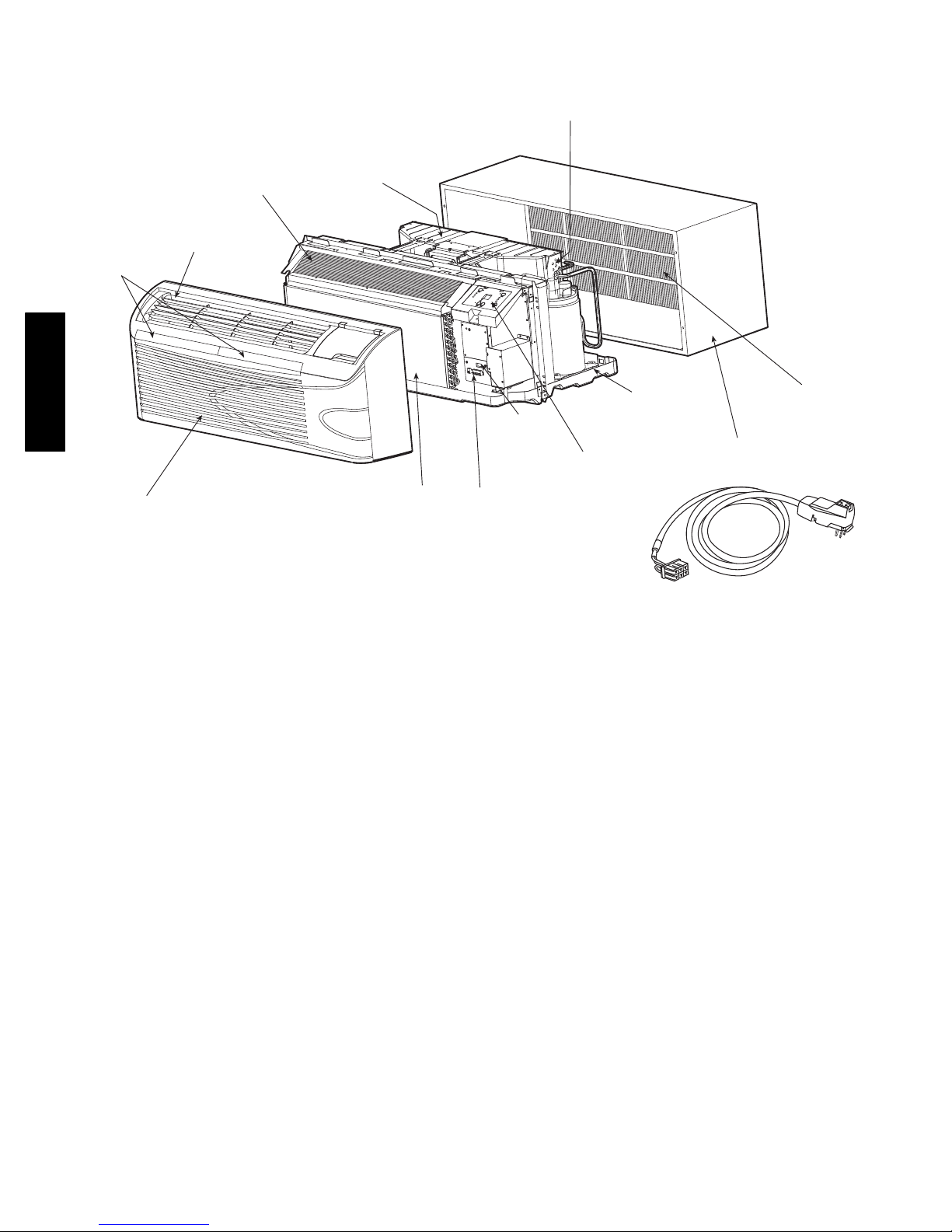
PRODUCT OVERVIEW (52M)
This section summarizes product features covered in detail in later sections of this manual.
COIL TUBE
SHEETS
BI-MOLDED
CONDENSER
SHROUD
INDOOR-AIR
FILTERS
WIRE SCREEN
DISCHARGE
GRILLE
52M
FRONT
PANEL
S Accessory P ower Cord or Ha rd wi re Kit
(required) -- Sel ect correct p ow er co rd or
hardwire kit to m at ch vol t ag e and amp erage of
electrical circuit.
S Polymer, Metal or Extended Wall S leeve --
Designed for rugged duty, acoustic absorption,
and attractive appearance for years to come.
S Rotary Compressors -- Provide quiet, reliable
operation.
S Copper Tube Aluminum Fin Coils -- Enhanced
coils provide durability, high performance, and
ease of operation.
S Fresh Air Control Arm -- Allows outdoor air into
room through vent filter for improved air quality.
S Control Door -- Provides protection for controls
and enhances appearance.
S Improved Condensate Removal -- Minimizes
condensate water on outside of building.
S New Two--Piece Filter Design -- Provides
improved air filtration and can be removed easily
for cleaning.
INDOOR
COIL
BASEPAN
CONFIGURATION
DIP SWITCHES
DIGITAL CONTROL PAD
W/ELECTRONIC DISPLAY
WALL THERMOSTAT
AND ENERGY MANAGEMENT
INTERFACE
Accessory Power Cord
ACCESSORY
WALL
SLEEVE
S Louvered Front Panel -- Made of high impact
polystyrene. Provides improved performance and
quiet operation.
S Bi--Molded Condenser Shroud -- T h e t w o -- p i e c e
condenser shroud al lo ws easy access for service
and maintenance to the outdoor coil and other
components.
S Digital Control Pad with Electronic Display --
Easy to select: mode, fan s peed and s et point with
an easy to read electronic display. In _For_C.
S Configuration Dipswitches -- Setup the system
perfect for th e exact application .
S Wall Thermostat I n terfa ce -- A t erm i nal block
for wiring up a wall thermostat that is easy to wire
to and i s easy to remove.
S EM (Energy Management) Interface -- A p l u g
for tying to an Energy Management system or
Front Desk Control. Easy to wire to and easy to
remove.
ACCESSORY
OUTDOOR
GRILLE
6
Page 7

PRODUCT FEATURES AND BENEFITS (52M)
S Improved sound for quiet operation
S Exceeds ARI (Air Conditioning and Refrigeration
Institute) minimum efficiency requirements with
exceptional energy efficiency ratios (EERs)
S Easy to operate digital keypad
S Easy to see electronic display
S Wall thermostat interface standard
S Energy Management interface standard
S Easy configuration for most applications
S Enhanced temperature and humidity control
S Self check/Self Correct features
S Improved condensate removal system
S Attractive, durable cabinet featuring new design
S Chassis that easily retrofits to most major
competitors’ sleeves without use of retrofit kit
S Low operating costs
S No bulky duct system
S No seasonal changeover
QUIET OPERATION
Occupants and neighbors are protected against noise
intrusion. Indoor sound reduction is achieved
through the units’ two --fan motor and tangential fan
design that provides a smooth, uniform air discharge.
Outdoors, the rotary compressor provides quiet,
reliable operation.
MOST EFFICIENT PERFORMANCE
HighEERs provide excellent operating economy. The
system operates without bulky ductwork, separate
equipment room, and complex match --up of different
components. Heating and Cooling modes are
available without seasonal changeover.
EFFICIENT FAN MOTOR
An efficient, to t all y enclosed PS C (permanent spl i t
capacitor)indoor fan motor provides a choice of high,
medium or low speeds for heating and cooling. A
fan--only setting provides air circulation. The fan
motors, both indoor and outdoor, require no
maintenance and no lubrication.
52M
7
Page 8
NO--RUST WEATHER LASTt
WALL SLEEVE AND FRONT PANEL
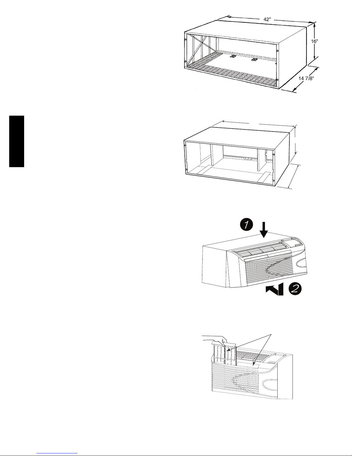
The indoor front panel and polymer wall sleeve use
nonmetallic compounds that never rust or corrode, do
not support combustion, and do not give off toxic
fumes. The weather-resistant feature exceeds
requirements of Underwriters Laboratories and resists
damage caused by impact and scratching. The
Weather Last feature also insulates and has up to 10
times the acoustic absorption of metal cabinets.
Insulated polymer wall sleeves combine all of the
above features with factory-installed insulation. The
insulation helps to reduce heat loss, save energy,
provide better sound absorption, and reduce the risk
of sleeve sweating.
Carrier’ s metal wall sleeves are available in a variety
of sizes for most standard and deep wall applications.
52M
All metal wall sleeves come with factory-installed
insulation, designed to minimize heat loss and reduce
outdoor noise transmissions into the room.
Standard Wall Sleeve (Polymer)
42 in.
16 in.
A07
633
Available in:
14-3/4 in.,
18 in.,
24 in.,
26 in.,
28 in.
REMOVABLE FRONT PANEL
The louvered front panel fits firmly onto the chassis
and features easy rem ov al for s erv i ce. It provides
front air intake to enhance performance and quiet
operation.
TWO--PIECE LIFETIME INDOOR
FILTER
New two--piece removable filters easily slide in and
out from t he front of the PTAC unit and are
interchangeable. The front panel does not need to be
removed t o access o r change th e filters. The filters are
washable and permanent.
Standard and Deep Wall Sleeve (Metal)
A07
381
Front Panel
2 Air filters
A07
381
Two--P iece Indoor Filter
8
Page 9
OUTDOOR AIR VENTILATION
)
The unique vent system is activated by a
two-- position control. Fresh outside air is redirected
by the vent door to an inside low --pressure area. A
molded plastic filter prevents dirt and debris from
entering the room side of the unit. The vent
mechanism i s m ad e from n on co rros i ve materi al
ensuring reliableoperation. A magnet on the door and
high--pres s ure airflow create a tight, draft free seal
when the vent door is closed.
The vent w ill provide up to 65 cfm of fresh air.
NOTE: If more fresh air cfm is required, a
Power--Vent Kit is available (see accessories).
BI--DIRECTIONAL DISCHARGE
GRILLE
The discharge grille is constructed of durable
polycarbonateand is reversible. Air flows upward at a
40 degree angle to the floor but can easily be adjusted
to an 80 degree angle to the floor.
A07550
Outdoor Air Ventilation
Air discharge upward
52M
Air discharge outward (Default)
A07550
Reversible Polycarbonate Discharge Grille
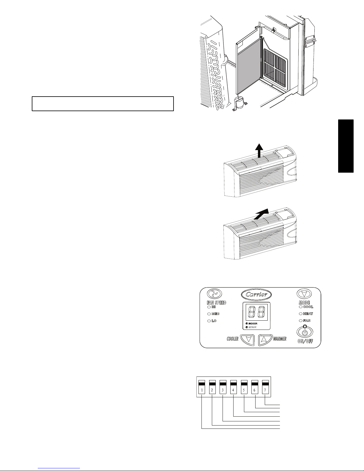
DIGITAL KEYPAD AND
ELECTRONIC DISPLAY
The digital keypad provides a simple to operate
control. The large, easy to pres s , “On/Off”, “Fan
Speed”, “Mode”, “Set p oi n t Up” and “Setp oi n t Down“
buttons make the control easy to operate. LEDs are
used to show the operating conditions selected.
Largenumbers are used to display the Setpoint, and if
configured, room air temperature.
SYSTEM CONFIGURATION
There are many different configuration possibilities,
through both dipswitches and the digital keypad, that
allow you to configure the unit for your exact
application. S ee Owner’s Manual for more detailed
informati on .
A07632
Electronic Display
Dipswitch
UP
Down
Freeze guard
Setpoint Limit 2
Setpoint Limit 1
Fan CON/CYC for cooling
Fan CON/CYC for heating
Wall Thermostat enable
Electric heat only (for Heat Pumps
A07072
Dipswitches
9
Page 10
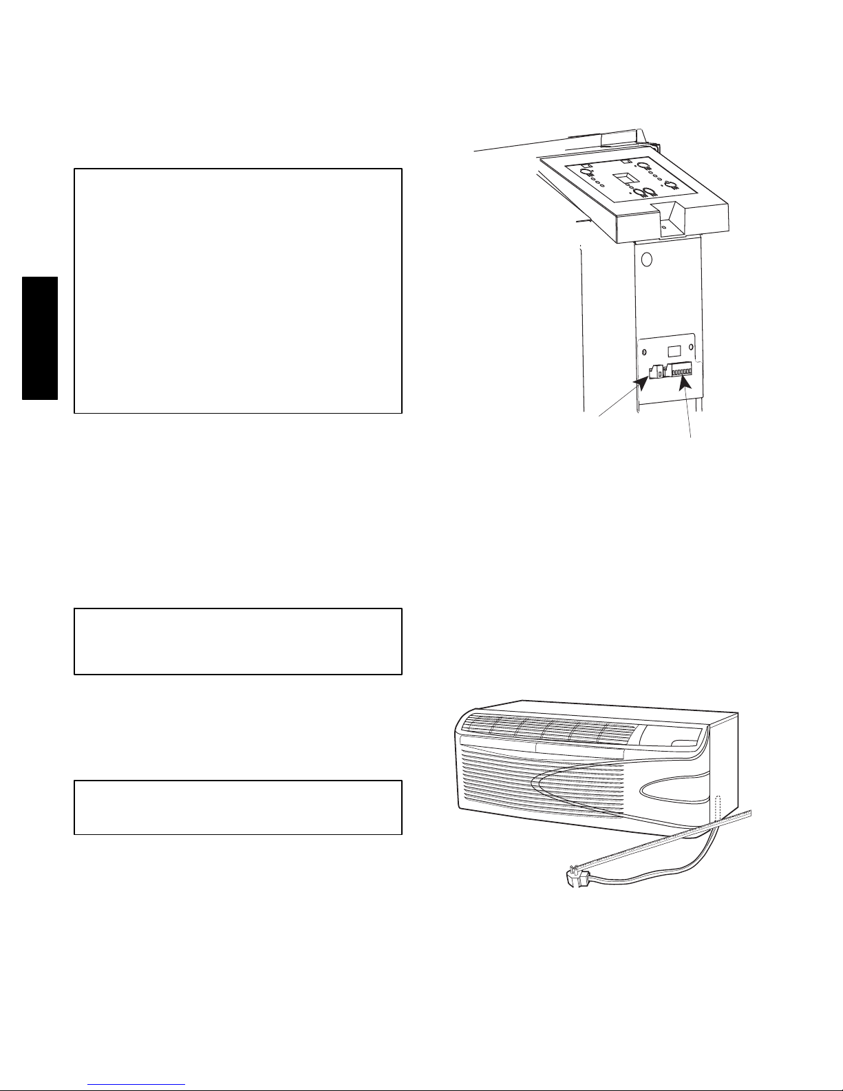
WALL THERMOSTAT INTERFACE
The standard wall thermostat interface provides a
simple to install thermostat connection. The unit has
a removable terminal connector to make field wiring
easy. See more info on wall thermostat connections
in the Dimensional Drawings and Installation Data
Section.
Notes:
— Thermostat wire is field supplied and
recommended wire size is 18 to 20 gage
solid thermostat wire.
— Wire should never be routed through the
wall sleeve.
— It is recommended to include extra wires
in case a wire breaks or is cut during
installation.
52M
— The thermostat is ordered separately and
a Carrier PTAC approved thermostat is
recommended, see the accessory chart in
the back.
EM (ENERGY MANAGEMENT)
INTERFACE
The EM interface is standard and provides a simple to
install, Energy Management connection. The unit has
a removable terminal connector to make field wiring
easy. When 24VAC is supplied to the input (the EM
connection), the unit will turn off. Once the 24VAC is
removed (becomes 0 volts), the unit will turn back
on.
Energy Management
Terminal Connections
Wall Thermostat
Terminal Connections
A07634
Wall Thermostat and Energy Management
Interface
Note: For more info, see the section in the back,
Typical Wiring Schematic For Energy
Management Interface.
POWER CORD FOR 265V UNITS
The 265v power cord extends 15--in. from bottom of
front panel and, per UL and National Electric Codes
(NEC), must plug into an electrical subbase.
Note: Accessory power cord and electrical
subbase sold separately. (See Accessory section
in back of this document.)
0
1
9
8
7
6
5
4
3
2
1
265V Power Cord
0
2
9
1
8
1
7
1
6
1
5
1
4
1
3
1
2
1
1
1
A07635
10
Page 11
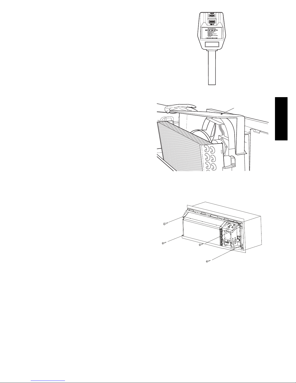
POWER CORD PROTECTION FOR
230/208V UNITS
The power cord for the 230/208--v unit provides
power cord protection by automatically
disconnecting power during an unsafe condition.
Power can be restored by pressing the RESET button.
BI--MOLDED CONDENSER SHROUD
The bi--molded condenser shroud provides easy
access for service and maintenance of the condenser
coil and related components.
A07551
Power cord Plug Hea d
BI-MOLDED
CONDENSER
SHROUD
52M
EASY ACCESS TO CHASSIS
Access to the chas s i s simply requires removing front
panel, th en fou r easy t o acces s s crews an d t hen
sliding t he chassis out of the sleeve for service or
maintenance.
A07677
Bi --Molded Condenser Shroud
A07057
Easy to Access Chassis
11
Page 12
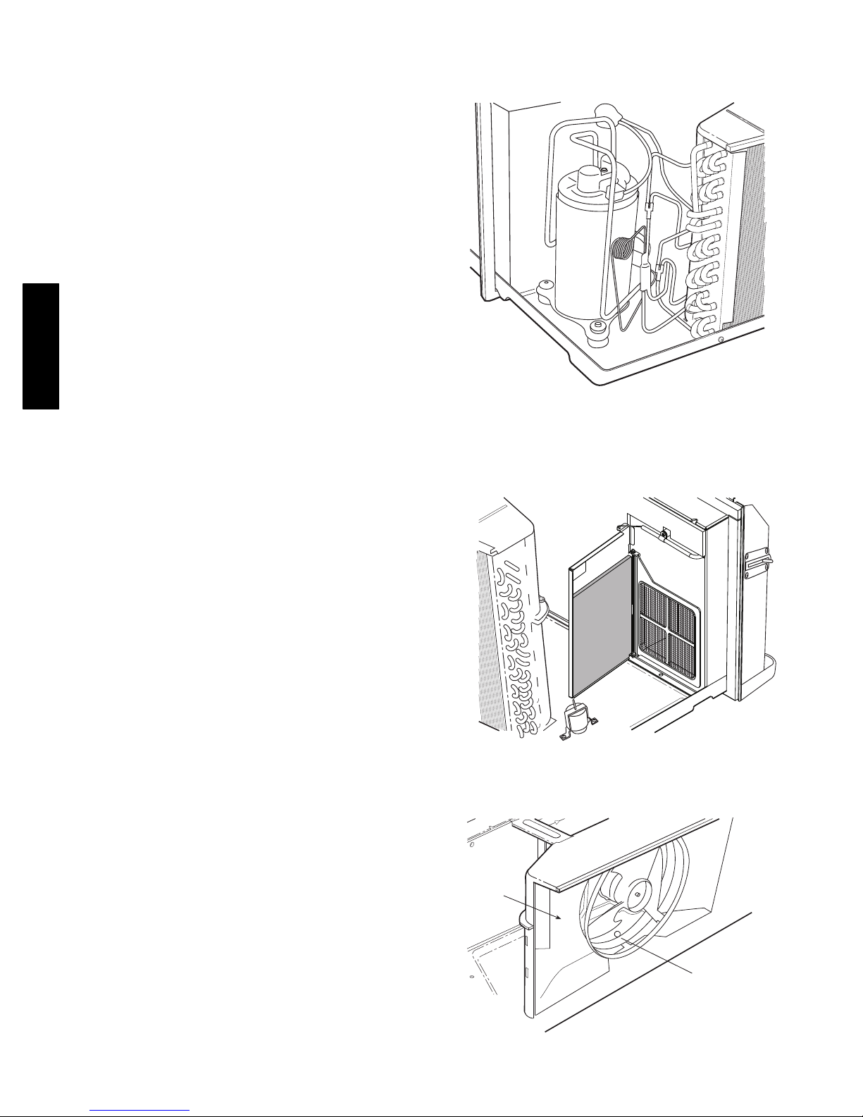
ENHANCED COPPER TUBING
Enhanced copper tubing is more efficient and durable
and can be repai red in t h e field, if required. B ecau s e
copper is a very stable metal, it is durable and resists
corrosion. Enhanced copper tubing increases:
S heat transfer capability
S the efficiency of the cooling and heating
processes
S thermal conductivity (by creating additional
tube surface and turbulent refrigerant gas
flow)
Every Carrier PTAC coil undergoes thorough leak
testing and pressure testing.
SEAMLESS BASEPAN
Seamless drawn bas ep an walls add p rot ect i o n against
water accu mu l at i on resu lting from storm--driven rain
52M
with heavy wind.
Carrier’s deep basepan holds up to 1 --3/4 gallons of
water without spilling. Closed cell foam insulators
are located between th e basepan and coils, keepi n g
coils from di rect contact with t h e b as epan an d
providing additional protection against corrosion.
A07552
CONDENSATE DRAIN VALVE
The t em perat u re --acti v at ed drain valve op en s when
the outdoor temperature drops below 55_F to prevent
water from freezin g in the basepan.
CONDENSATE REMOVAL
Carrier’s 52M S eries unit has a new condensate
(water) disposal system. In addition to slinger ring
technology, Carrier has developed and patented a
Condensate Suction Port. The suction port, along
with the slinger ring, draws i n water which is sprayed
up onto the outdoor coil. The water then evaporates,
thus providing better disposal of excess condensate
and improving unit efficiency.
NOTE: If it is necessary to control 100% of the
condensate, the Carrier Drain Kit (Part No.:
DRAIN--KIT--4PK) is recommended.
A07550
Condensate Drain Valve Prevents Water
from Freezing in Basepan
SLINGER
RING
CONDENSATION
SUCTION PORT
CONDENSER SECTION
A07678
Condensate Removal System
12
Page 13
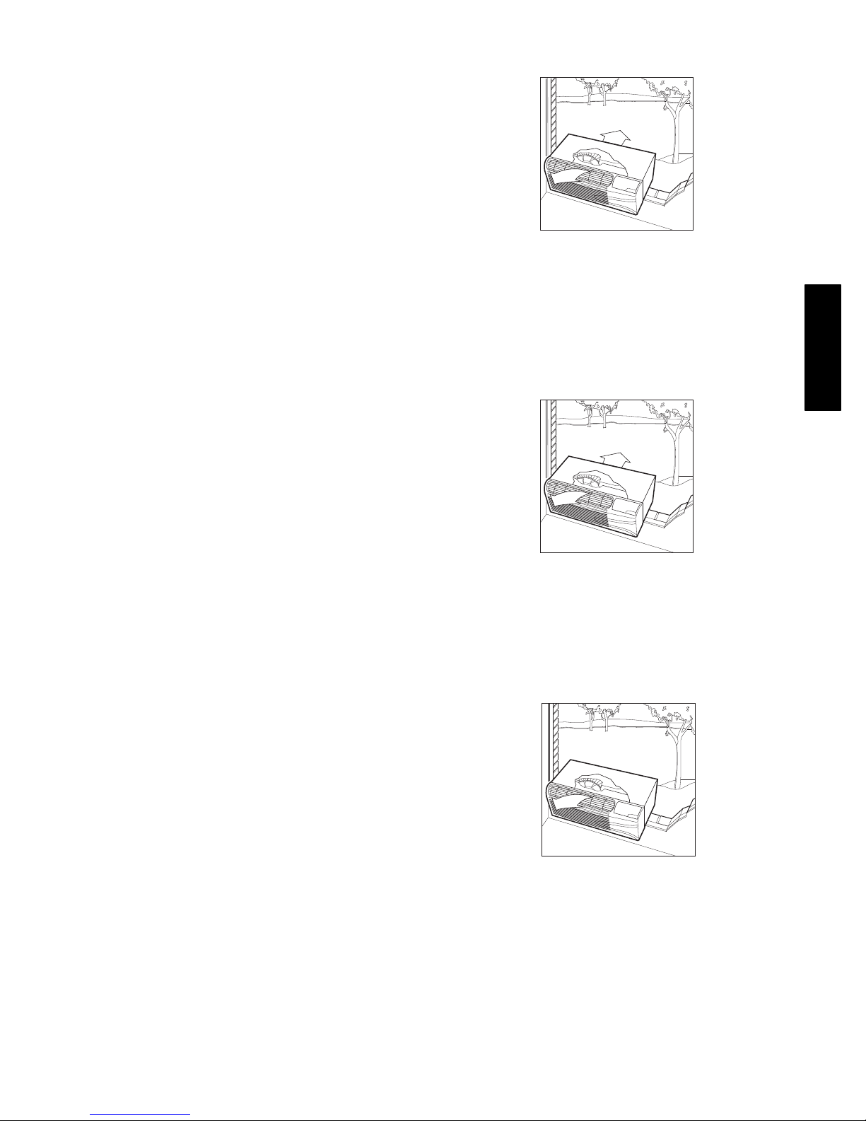
HEAT PUMPS PAY THEIR
OWN WAY
Heat pump models are available at a nominal
additional cost. In many locales, the payback is
realized in just a few months. Cost and payback
details are provided on the next page.
SPECIAL FEATURES
Two-Stage Thermostat:
The indoor thermostat senses the indoor temperature
and automaticall y turns on the el ectri c heat to warm
the room quickly. After the desired temperature
conditions have been satisfied, the thermostat
automatically switches to heat pump mode. If
compressor failureoccurs, the thermostat will provide
backup electric heat automatically.
Outdoor Thermostat:
During the heating cycle, the outdoor thermostat
senses outdoor coil temperature. It switches the unit
to electric heat mode when the outdoor coil
temperature is 28_F or below for one minute. The
thermostat switches the unit back to heat pump mode
when the outdoor coil temperature rises above 40_F
for ten minutes, which is enough to provide heat to
meet demand. The entire operation is completely
automatic.
Reversing Valve:
The reversing valve provides quiet refrigerant flow
after the unit shuts off. The valve controls the
direction of refrigerant flow for both heating and
cooling functions and remains energized as long as
the controls are in the heat position. When the
cooling controls are activated, the valve automatically
reverses to the cooling position.
Manual Compressor Override Configuration:
This configuration dip switch completely locks out
the compressor. Note that the compressor and heater
do not operate at the same time, thus conserving
energy.
HOW THE HEAT PUMP WORKS
A07553
In Hot Weather:
Carrier’s PTAC units provide indoor comfort in the
same manner as conventional air conditioners,
removing heat and humidity from indoor air. The heat
and humidity is released to the outdoors. Carrier’s
high efficiency design saves energy and reduces
cooling costs.
A07553
In Cool Weather:
When the outdoor coil temperature is above 28_F, th e
heat pump draws heat from outdoor air and uses it to
heat indoor air. S ince heat is transferred and not
produced, Carri er’s heat pump uses less el ect ri ci t y
and reduces energy costs signi fi can t l y.
52M
A07554
In Sub- Freezing Weather:
When the outdoor coil temperature falls below 28_F
for one minute, the unit automatically switches on a
built--in electric heater. The compres s or sto ps and the
indoor fan circulateswarm air produced by the heater.
When the outdoor coil temperature rises above 40_F
for ten minutes, heat pump operation resumes
automatically.
13
Page 14
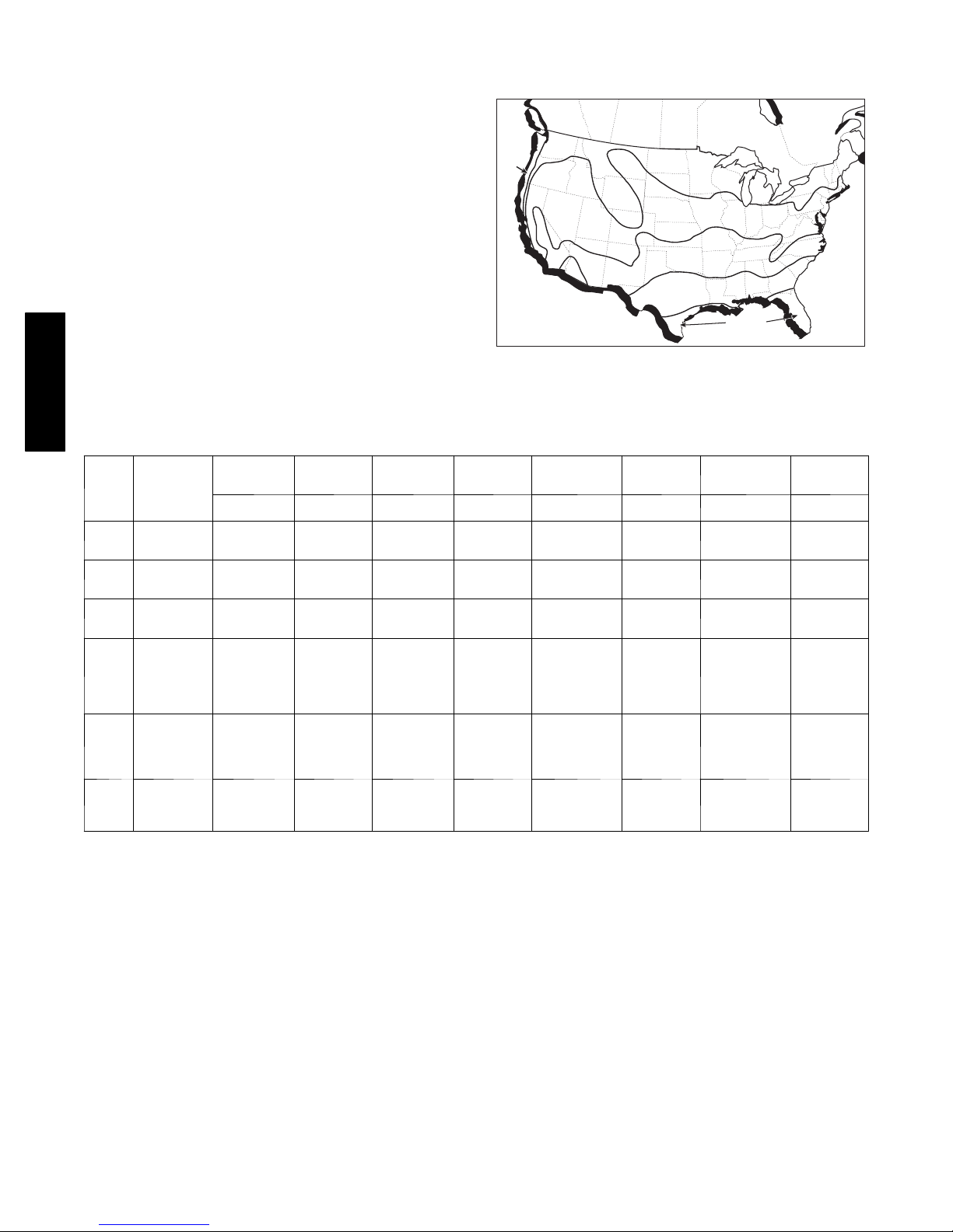
HEAT PUMP ENERGY
SAVINGS
Heat pumps save more on operating costs during the
heating cycle than heat/cool models. The table below
shows that the higher initial cost of purchasing a heat
pump i s quickly made up in lower operating costs.
Use the map to identify the climate zone’s designated
number. Reading down the left--hand column of the
table, select the cost/kWh rate in this zone that most
closely approximates your local rate. The
approximated savings and payback period is found at
the intersection of your zone/rate line and the desired
Btuh Co ol i n g C ap aci t y col u m n. Exact sav i n gs are
determined by lifes t yl e, l ocal elect ri cal rat es , and
climatic conditions.
For more precise energysavings in your geographical
location, go to www.lodgingAC.com to use Carrier’s
52M
energy calculator.
CARRIER HEAT PUMP INITIAL COST VERSUS SAVINGS OVER HEAT/COOL MODELS
7000 BTUH1
COOLING
CAPACITY
Annual
Savings*
$ 34.26
$ 45.68
$ 57.10
$ 57.12
$ 76.16
$ 95.20
$ 58.02
$ 77.36
$ 96.70
$ 82.02
$109.36
$136.70
$164.04
$191.38
$218.72
$ 57.36
$ 76.48
$ 95.60
$114.72
$133.84
$ 93.72
$124.96
$156.20
$187.44
I
II
III
IV
V
VI
LEGEND
ELECTRIC
COST/kWH
$.06
$.08
$.10
$.06
$.08
$.10
$.06
$.08
$.10
$.06
$.08
$.10
$.12
$.14
$.16
$.06
$.08
$.10
$.12
$.14
$.06
$.08
$.10
$.12
ZONE
kWH --- Ki l o w a t t Ho u r
* Computer projections based on full cooling load at 95 F. Savings projected for 230 v ratings.
1 Heating load is 5,000 Btuh at winter design point temperature.
2 Heating load is 10,000 Btuh at winter design point temperature.
3 Heating load is 15,000 Btuh at winter design point temperature.
$60
PREMIUM
Payback in
Months
21
16
13
13
9
8
12
9
7
9
7
5
4
4
3
13
9
8
6
5
8
6
5
4
9000 BTUH2
COOLING
CAPACITY
Annual
Savings*
$ 43.08
$ 57.44
$ 71.80
$ 71.76
$ 95.68
$119.60
$ 72.84
$ 97.12
$121.40
$103.02
$137.36
$171.70
$206.04
$240.38
$274.72
$ 71.94
$ 95.92
$119.90
$143.88
$167.86
$117.66
$156.88
$196.10
$235.32
PREMIUM
Payback in
Months
$75
21
16
13
13
12
13
9
8
9
7
9
7
5
4
4
3
9
8
6
5
8
6
5
4
ZONE
VI
V
II
12000 BTUH2
COOLING
CAPACITY
Annual
Savings*
$ 58.20
$ 77.60
$ 97.00
$ 96.96
$129.28
$161.60
$ 98.40
$131.20
$164.00
$139.14
$185.52
$231.90
$278.28
$324.66
$371.04
$ 97.26
$129.68
$162.10
$194.52
$272.33
$159.00
$212.00
$265.00
$318.00
$90
PREMIUM
Payback in
Months
19
14
11
11
8
7
11
8
7
8
6
5
4
3
3
11
8
7
6
4
7
5
4
3
ZONE V
ZONE IV
ZONE III
ZONE II
ZONE I
15000 BTUH3
COOLING
CAPACITY
Annual
Savings*
$ 68.34
$ 91.12
$113.90
$113.64
$151.52
$189.40
$115.38
$153.84
$192.30
$163.14
$217.52
$271.90
$326.28
$380.66
$435.04
$113.94
$151.92
$189.90
$227.88
$265.86
$186.48
$248.64
$310.80
$372.96
A07555
$110
PREMIUM
Payback in
Months
19
14
12
12
9
7
11
9
7
8
6
5
4
3
3
12
9
7
6
5
7
5
4
4
For more precise energy savings in your geographical location, go to www.lodgingAC.com to use
Carrier’s energy calculator.
14
Page 15
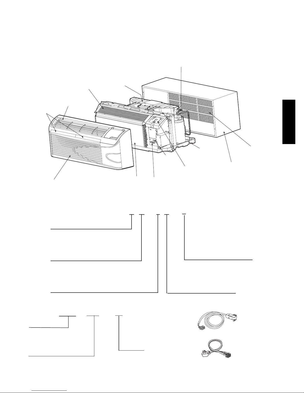
ORDERING DATA
For immediate assistance, call 1--800 --827--7435 or contact you r local Carrier dealer.
Standard Unit
S Chassis with front panel
S Electronic controls with touchpad and digital display
Lead--time: Many models are in stock for immediate delivery; call for lead--times.
COIL TUBE
SHEETS
BI-MOLDED
CONDENSER
SHROUD
INDOOR-AIR
FILTERS
WIRE SCREEN
DISCHARGE
GRILLE
52M
INDOOR
FRONT
PANEL
COIL
PRODUCT CATALOG NUMBER
52 ME – U 12 – – – 3
Series Designation
PTAC (Packaged Terminal Air Conditioner)
Performance Series
ME – Cooling with Electric Heat
MQ – Heat Pump
Electric Heater Size
U – Universal (defined by power cord)
CONFIGURATION
DIP SWITCHES
DIGITAL CONTROL PAD
W/ELECTRONIC DISPLAY
WALL THERMOSTAT
AND ENERGY MANAGEMENT
INTERFACE
Electrical Data
3 – 230/208-v, 60 Hz
4 – 265-v, 60 Hz
Cooling Capacity (nominal)
07 – 7,000 Btuh
09 – 9,000 Btuh
12 – 12,000 Btuh
15 – 15,000 Btuh
BASEPAN
ACCESSORY
WALL
SLEEVE
ACCESSORY
OUTDOOR
GRILLE
A06752
ACCESSORY POWER CORD (REQUIRED) CATALOG NUMBER
PWRCORD
Kit Description
PWRCORD = Power Cord
Voltage
230v = 230/208-v, 60 Hz
265v = 265-v, 60 Hz
230v
–
–
20A
*Power Cord
Amperage
15A = 15 Amps
20A = 20 Amps
30A = 30 Amps
A07636
for 230v*
*Power Cord
for 265v
A07637
15
Page 16
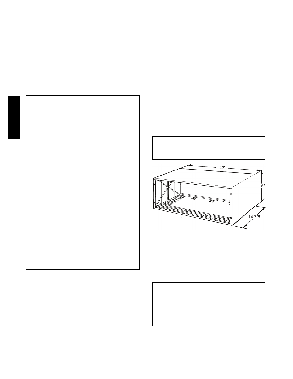
FIELD--INSTALLED ACCESSORIES
WALL SLEEVES
Weather Lastt Wall Sleeve
For the best performance and longest life, Carrier
recommends genuine Carrier wall sleeves for all
installations.
All Carrier wall sleeves are built with a pitch of 1/4
in. per foot; for self--pitching of the unit, the wall
sleeve must be installed level (any error should be
pitched to the outside). Overflow slots on the outside
of the sleeve are in pl ace to divert excess wat er
during severe weather.
Important Sleeve Installation Considerations:
S All Carrier sleeves are self pitching and must
be mounted level in all directions. (Do not use
52M
rails to level sleeve.)
S The sleeve should be caulked on all sides,
including both inside and outside the
building.
S If more than 4 in. of wall sleeve projects into
the room, an accessory subbase must be used
for support.
S For all applications with an accessory
subbase, wall sleeve must extend 3--1/4 in.
minimum into room and must be 3--1/4 in.
minimum to 5--1/2 in. maximum above floor
(including carpeting) to allow for proper fit of
subbase.
S For applications where the wall sleeve is
mounted flush to the exterior of the
building(or recessed in), Carrier recommends
a field--supplied drip edge be installed to
prevent water infiltration into the building.
S Insulated wall sleeves should be considered
for superior sound absorption, to reduce heat
loss and to prevent sleeve sweating, a
condition that can occur when the outside
temperature is cold and the indoor conditions
are warm and humid.
Polymer Wall Sleeves
Choose a polymer wall sleeve for maximum
protectio n and appearance.
All Carrier’s polymer wall sleeves are made from a
molded polymer that is designed for strength and
durability. This material has excellent corrosion
resistance and a flammability rating of UL94-- 5V.
The sleev e surface is textured to prevent shine and
hide scratches. The rib configuration on the sleeve
bottom allows easy chassis removal and aids in
drainage. The locating holes in the side and top
panels allow for easy fastening of the sleeve to wall
openings. R efer to dimension drawings for typical
wall installation and dimensions.
The sleeve’s alp i ne m i s t co l or (a shade of beige)
closely matches the front panel and blends in well
with any inside or outside decor.
The polymer wall sleeve comes in both insulated
(factory installed) or non--insulated, to meet the
requirements of every application.
Insulated Polymer Wall Sleeve
Part No.: S LEEVE --INSUL--1PK
Carrier ’s accessory in s ul at ed po l y mer wall sleeve,
with factory--installed insulation, provides superior
sound absorption, reduces heat loss and prevents
sleeve sweating, a condition that can occur when the
outside temperature is cold and the indoor conditions
are w arm and humid.
IMPORT ANT: Insulated Polymer Wall sleeve
provides superior sound absorption, reduces
heat loss and prevents sleeve sweating.
A07633
Corrosion -- Pr ot ect ed Polymer Sleeve
Non--Insulated Polymer Wall Sleeve
Part No.: WALL --SLEEVE --1PK
Carrier ’s accessory non--insul at ed polymer wall
sleeve provi des a superio r app earance and prot ect i o n
for many applications.
For applications where weather conditions
could influence sleeve sweating, a condition
that can occur wh en t h e ou t s i de temperature is
cold and the indoor conditions are warm and
humid, the Insulated Polymer Wall sleeve
should be considered.
16
Page 17
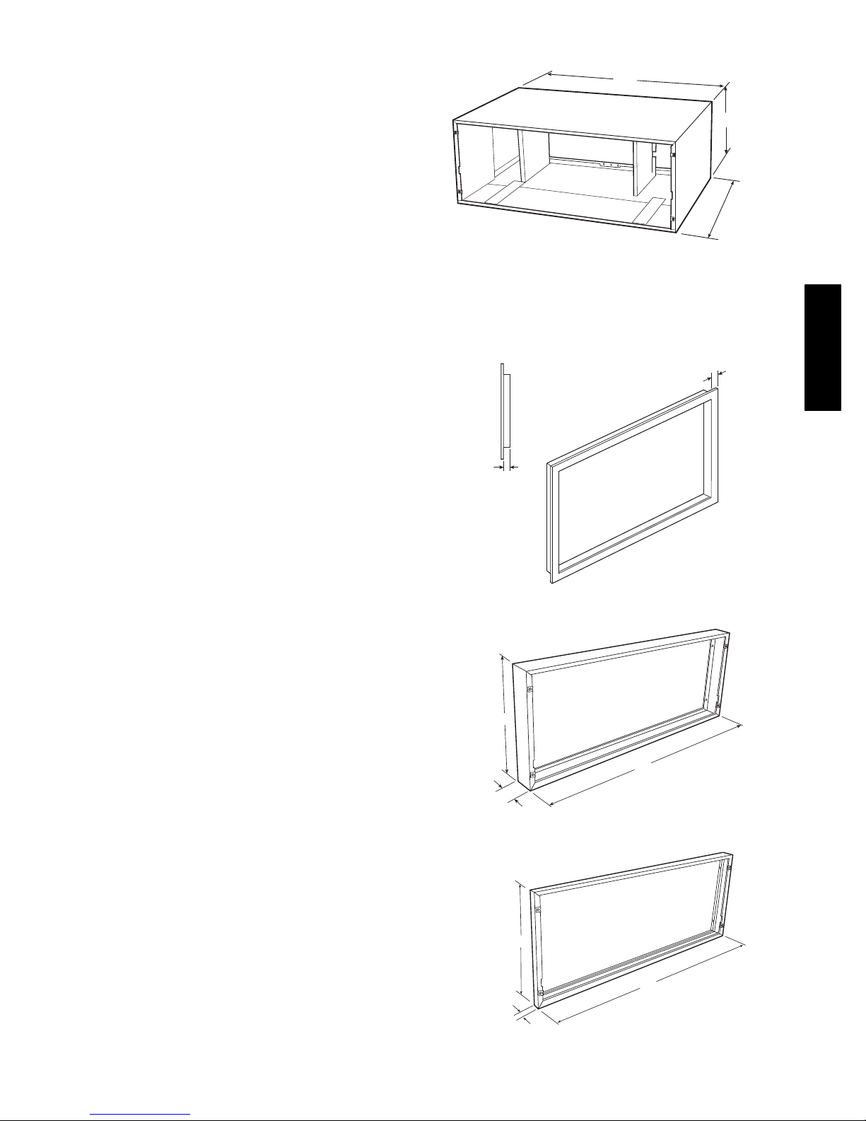
FIELD--INSTALLED ACCESSORIES (CONT.)
Insulated Metal Wall Sleeves
Part No.: SLEEVE-- S TEEL --1PK
Part No.: SLEEVE-- EXT18 --1PK
Part No.: SLEEVE-- EXT24 --1PK
Part No.: SLEEVE-- EXT26 --1PK
Part No.: SLEEVE-- EXT28 --1PK
Carrier ’s metal wall sleeves are avail abl e i n a variety
of sizes for most applications and difficult
installations. Choose from 14-- 3/4 in., 18 in., 24 in.,
26 in. , or 28 in. standard depth sizes. All metal wall
sleeves come with factory--installed insulation,
designed to minimize heat loss, reduce outdoor noise
transmissions into the room and prevent sleeve
sweating. In addition, the metal wall sleeve provides
a flammability rating higher than UL94--5V.
Wall Sleeve Molding Kit
Part No.: S LEEVE --MOLDING
For a superior look and to hide any construction
imperfections, use Carrier ’s wall sleeve molding kit
to trim the wall sleeve to the wall. The molding kit is
a perfect solut i on and can be used wi t h any Carrier
wall sleeve (matches Carrier wall sleeve color).
42 in.
16 in.
Available in:
14-3/4 in.,
18 in.,
24 in.,
26 in.,
28 in.
Standard and Extended Metal Wall Sleeve
1 IN.
1/2 IN.
52M
Friedrich (and ZoneAire) Retrofit Wall Sleeve
Adapter
Part No.: F R-- S LEEVE --EXT
The Friedrich (and ZoneAire) wall sleeve adapter is
constructed of sheet metal and is designed to increase
the depth of an exist in g Fri edri ch T--series or
ZoneAire wall sleev e to accom m o dat e Carri er’s
industry standard PTAC units.
Climate Master Wall Sleeve Adapter
Part No.: C M --SLEEVE --EXT
TheClimate Masterwall sleeve adapter isconstructed
of sheet metal and is designed to increase the depth of
an existing Climate Master 12--1/2 in. wall sleeve to
accommodateCarrier ’si ndust rystandard PTACunit s.
Wall Sleeve Molding Kit
16 IN.
42 IN.
3 IN.
Friedrich Wall Sl eeve Adapter Kit
16 IN.
42 IN.
1 1/2 IN.
Climate Master Wall Sleeve Adapter Kit
17
Page 18
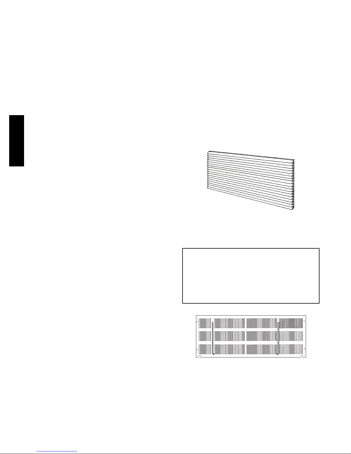
FIELD--INSTALLED ACCESSORIES (CONT.)
OUTDOOR GRILLES
Carrier recommends only the use of Carrier--supplied
grilles for use on the 52M series units. However, the
architectural designs of a building may dictate the use
of special or oversized grilles and/or louvers. Special
louvers or any special architectural treatment of the
buildi ng facade that m ay restrict free circu l at i on o f
condenser airflow should be referred to Carrier
Corporation for evaluation and approval.
Aluminum Architectural
Outdoor Grilles ( Louvered)
Part No.: GR ILLE --ALU--CLEAR (anodized aluminum)
Part No.: GR ILLE --ALU--WHITE
Part No.: GR ILLE --ALU--BEIGE
52M
Part No.: GR ILLE --ALU--ALPIN
wall sleeve)
Part No.: GR ILLE --ALU--BRONZ
Part No.: GR ILLE --ALU--MBR NZ
Part No.: GR ILLE --ALU --BROWN
Part No.: GR ILLE --ALU--LGREY
Part No.: GR ILLE --ALU--SGREY
Part No.: GR ILLE --ALU--PEACH
Part No.: GR ILLE --ALU--MELON
Part No.: GR ILLE --ALU--RDBR K
Part No.: GR ILLE --ALU--BLUE
Part No.: GR ILLE --ALU--GREEN
This premium line of decorative outdoor grilles will
enhance the appearance of any building. The grilles
are made of strong, durable, extruded, anodized
aluminum and are designed to be mounted easily
from inside the room. These elegant grilles, available
in man y standard colo rs, have baked enam el fi n i s hes
containing 50% Kynarr resin, for a superior finish
that will withstand the most extreme conditions.
(color matches Carrier
Polymeric Architectural Outdoor Grilles
(Louvered)
Part No.: GR ILLE --PLA-- B R OWN
Part No.: GR ILLE --PLA --BEIGE
Part No.: GR ILLE --PLA --ALPIN
(color matches Carrier wall sl eev e)
This value line of polymeric architectural outdoor
grilles will blend attractively with most building
exteriors. Mounted easily from inside the room, the
one--piece, mo l d ed grille is designed for protection,
enhanced appearance, and superi o r
weather--resistance. The grille is made of durable
polymer and has a colorfast, lightly textured finish
that blends well with most exterior finishes.
Architectural Grille in
Aluminum or Pol y me r ic
NOTE: Color sam ples can be ordered in packs of 10
through your Carrier Sales Representative.
(Distributors: orde r part number 02-- CLRGR001--10
through Li terat ure Distribution).
For more information on custom colors and sizes,
contact Reliable Products at 1--800 --239--4621
Standard Outdoor Aluminum Grille
Part No.: GR ILLE --ALU--STAMP
This cost--effective, one --piecestandard grilleis made
from durable anodized aluminum. The grille is
lightweight, has a clear finish, and is easy to install
from inside the room.
Standard Grille
18
Page 19
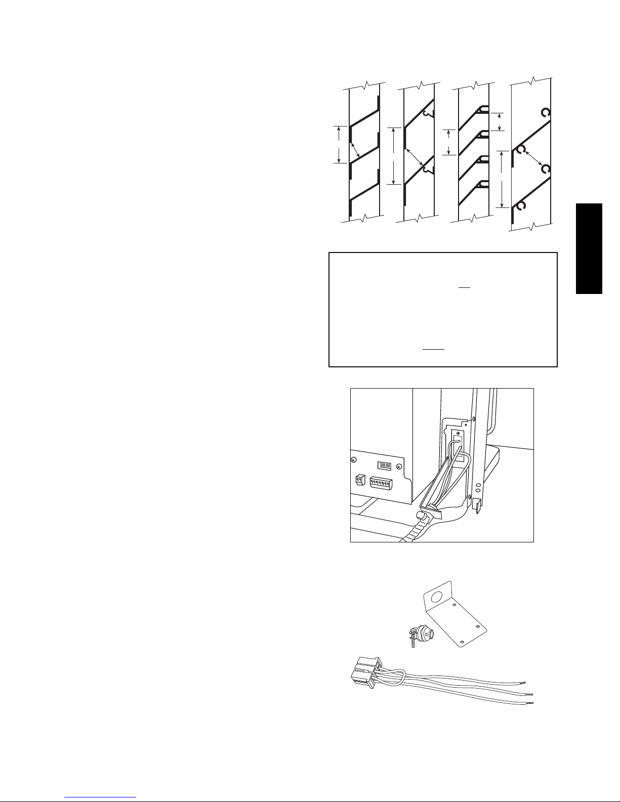
FIELD--INSTALLED ACCESSORIES (CONT.)
OUTDOOR GRILLE SELECTION
IMPORTANT: If you wish to use a grille not made
by Carrier for your Carrier unit(s), contact
Carrier Application Engineering.
The following guidelines must be followed in the
initial selection of any alternate exterior grille or
louver:
1. The louver must have a minimum of 65% free
area. Free area is the minimum area of the
opening in an air inlet or outlet in which air can
pass. Free Area (%) = X/Y.
2. The louver should be attached to the wall sleeve
in a manner that will prevent recirculation of
condenser discharge air into the inlet. In most
applications, baffles, splitters, and/or gasket
will be required between the chassis tube end
sheets and the louver to prevent air
recirculation.
The above criteria must be followed, since a louver
that is restrictive or allows re--circulation will result
in a reduction of the unit’s capacity and efficiency
and will ultimately shorten the compressor life.
Y
X
Louver Dimensional Refer ence
F.A. (%) =
Y
X
Y
Sample Calculations
Free Area (%) =
x = 1
y = 1.5
1
x 100 = 66.7%
1.5
x
y
X
X
Y
52M
x 100
Hardwire Kit
Part No.: 52M-- HDWR --KIT--15A
52M--HDWR--KIT--20A
52M--HDWR--KIT--30A
This access ory hardwire kit p rov i des a perm anen t
connection to the unit. Electrical hard wiring is
required when NEC (National Electrical Code) or
local co des restrict the u se of power cord and plug
connections. The hardwire kit easily mounts on the
front right side of the unit and comes with 36 inches
of flexible steel conduit.
Conduit Interface Kit
Part No.: 52M--C ONINT --15A
52M--CONINT--20A
52M--CONINT--30A
The conduit interface accessory kit provides an eas y
wire connection to the unit to interface to existing
field--supplied conduit.
A07381
Hardwire Kit
A07810
Conduit Inter f a ce Kit
19
Page 20
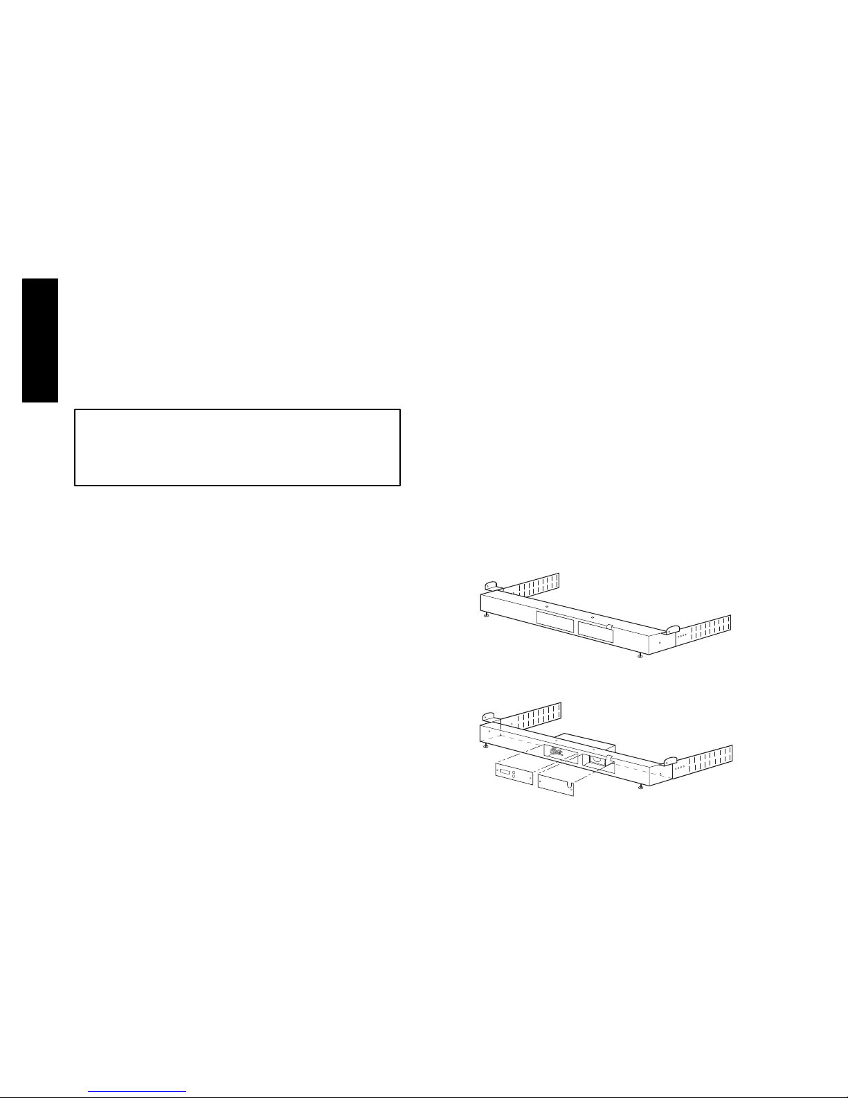
FIELD--INSTALLED ACCESSORIES (CONT.)
SUBBASE
Part No.: SUBBASE --230V--15A
Part No.: SUBBASE --230V--20A
Part No.: SUBBASE --230V--30A
Part No.: SUBBASE --265V--15A
Part No.: SUBBASE --265V--20A
Part No.: SUBBASE --265V--30A
This decorative subbase supports the unit and is
available i n th ree basic m od el s: non--electrical ,
electrical, and hardwired.
A subbase (or leveling legs) is required for
installations where the wall sleeve extends 4 or more
inches into the room or the wall is less than 2 in.
52M
thick. The minimum clearance betweenthe bottom of
the sleeve and the floor is 3--1/4 in., and the
maximum clearance is 5--1/2 inches.
IMPORT ANT: All standard cord--connected
265--v PTAC units will require a
field--installed electrical subbase accessory
per UL and NEC electrical codes.
Part No.: S UBB ASE-- NON --ELEC
Part No.: LEVELING --LEGS
All subbase models are pre-- assembled, mount to the
wall sleeve, and come with adjus t ab l e legs and side
skirting to provide a finished appearance.
Non-Electrical Subbase
The easy to install, non--electrical subbase provides
mechanical support and requires no wiring.
Electrical Subbase
The electrical subbase has a factory--installed
electrical juncti on box contain i n g a recept acl e for
corded packaged terminal ai r conditi on er (P TAC)
units. The electrical subbase series offers models
from 230 --v, 15 amp up to 265--v, 30 amp. Knockouts
are provided for power source connections.
Non-- E le ctr i cal Subba se Assembly
Electrical Subbase Assembly
20
Page 21
FIELD--INSTALLED ACCESSORIES (CONT.)
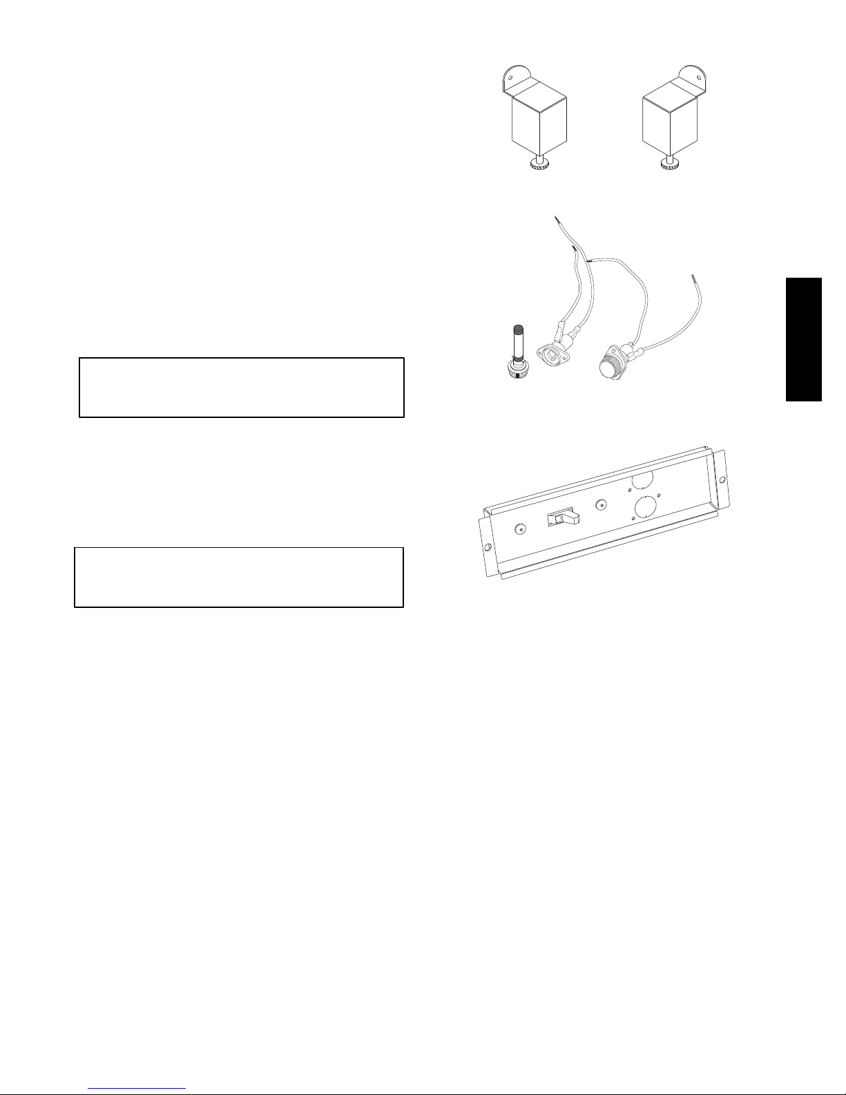
Leveling Legs
Part No.: LEVELING --LEGS
Leveling legs attach eas i l y to Carrier’s wall sleeve
and offer accurat e leveling and support for units
without a subbase. Leveling legs are adjustable from
3-- 1/4 to 5--1/2 inches.
Subbase Fuse Kit
Part No.: SUBBASE-- FUSE--15A
Part No.: SUBBASE-- FUSE--20A
Part No.: SUBBASE-- FUSE--30A
The fuse kit provides i n--line overcurrent protection at
the unit when required by NEC (National Electric
Code) or local codes.
IMPORTANT: The Fuse Kit can only be
used with the electrical or hardwired
subbase.
Leveling Legs
52M
Subbase Fuse Ki t
Subbase Power Disconnect Switch
Part No.: SUBBASE-- SWITCH
The subbase power disconnect 2 --pole switch
provides a recessed power disconnect for the PTAC
unit when required by NEC or local codes.
IMPORT ANT: This accessory can only be
used with the electrical or hardwired
subbase.
O
N
Power Disconnect Switch Assembl y
21
Page 22
FIELD--INSTALLED ACCESSORIES (CONT.)
THERMOSTATS
Carrier’s full line of wall thermostats are designed to
enhance every PTAC application. Wall thermostats
are simple and easy to use. Wall thermostats provide
better temperature and humidity control as they can
be placed i n an optimal position in the room.
NOTE: See wiring diagram of multiple PTAC
units controlled by one thermostat.
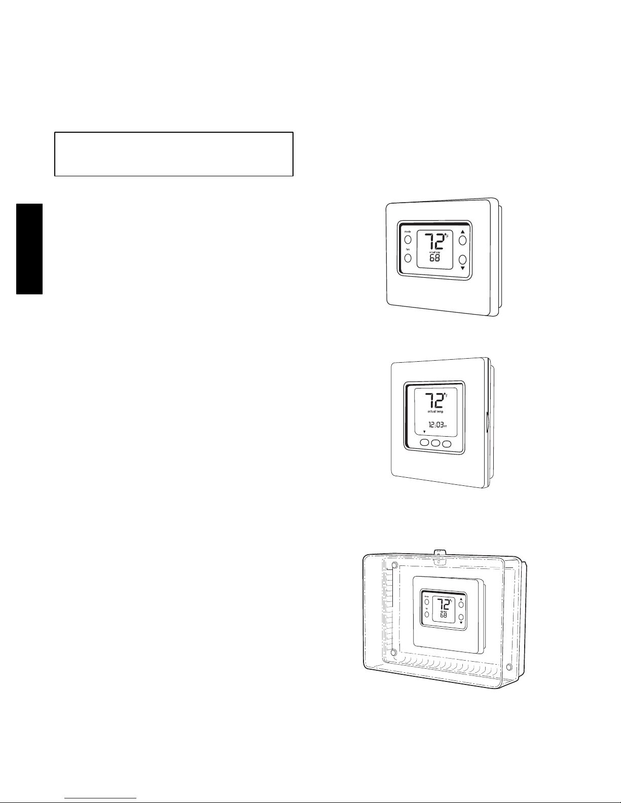
Non--Programmable Thermostat
Part No.: PTACS TAT --NP--HC --A (heat/ cool models )
Part No.: P TACSTAT--NP--HP --A (heat pum ps)
This low--voltage, easy-- to --use non--programmable
52M
thermostat provides maximum guest comfort.
A07135
Non -- Programmable Thermostat
Digital Programmable Thermostat
Part No. : TC-- PAC--01 (heat/cool models)
Part No. : TC--PHP--01 (heat pumps)
This micro computer controlled, 7--day
programmablewall t hermostat has enhanced features
that provide automatic control for both heat pumps
and heating/cooling units.
Thermostat Locking Cover
Part No.: TS TAT--COVER-- 6 X7
Part No.: TS TAT--COVER --7X10
The thermostat locking cover prevents unauthorized
access to t h e thermost at .
A07136
Programmable Thermostat
A07745
Thermostat Lo cki ng Cover
22
Page 23
FIELD--INSTALLED ACCESSORIES (CONT.)
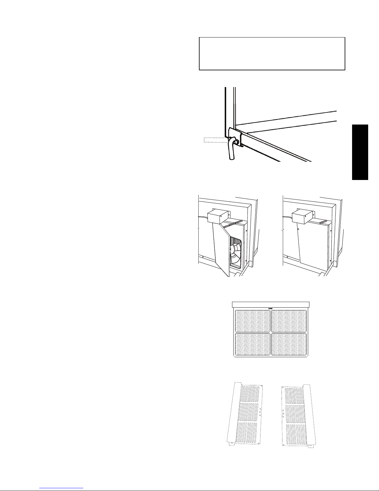
Condensate Drain Kit
Part No.: DR AIN --KIT--4PK
This universal drain kit may be used internally or
externallyto route condensate to a drainage system. It
can be field--instal l ed on any C arri er wall sleeve.
Although Carrier units are designed to dissipate all
the condensate generated during normal cooling,
there may be times when abnormal conditions cause
more condensate than the unit can dissipate. If
condensate that drips from the wall sleeve is
objectionable, this internal/external drain kit should
be installed.
The drain kit may be attached to the exterior right or
left side of the wall sleeve for external draining or
mounted to the room side of the wall sleeve for
internal draining.
A 6 inch straight tube and 90_ curved t u be are
supplied to simplify any application (1/2” OD
copper).
Power Vent with Power Door Kit
Part No.: 52M --PWRVENT--DOOR
Carrier’s power vent kit, utilizing a specially
designed fan, when installed in the unit’s fresh air
vent, will supply up to 95 cfm of outside air into the
room. The power vent will only operate when the unit
fan runs, and the unit will automatically open or close
the vent door, depending on the operation of the fan.
The kit comes pre--assembled from the factory and is
very easy to install.
IMPORTANT: For internal drains installed
in the plastic wall sleeve, the d rain must be
installed on the flat area of the sleeve. It
cannot be installed in the wafer area.
Power Vent with Door Kit
Drain Kit
A07748
A07749
52M
Replacement Filters
Part No.: 52M --AIRFILT --10PK
The C arri er 52M m od el replacement air filters come
in packages of 10. The filters save energy by
preventing the evaporator coils from being plugged
with dirt and lint. These economical and sturdy filters
are interchangeable and may be washed, vacuumed,
and reused.
Baffle Kit
Part No.: BAFFLE--KIT--1PK
the accessory baffle kit ensures a good seal between
the unit and the exterior grille to prevent air
recirculatio n , which can cause system failure. The
accessory b affle k it is required for ap p li cat i on s where
a factory wall sleeve is used without a factory exterior
grille.
A07749
Replacement FIlters
A07275
Baffle Kit
23
Page 24
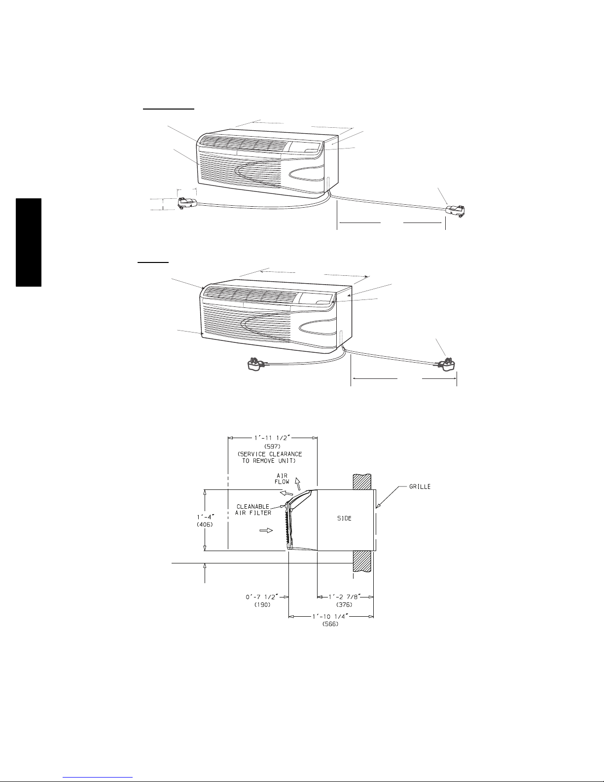
DIMENSIONAL DRAWINGS AND INSTALLATION DA TA -- NEW
CONSTRUCTION
Proper building practices must be used when
constructing a wall opening to support a PTAC wall
sleeve and chassis.
208/230--v
DISCHARGE
GRILLE
REMOVABLE
FRONT PANEL
3.94"
(100)
2.03"
(51.6)
52M
265--v
DISCHARGE
GRILLE
If practices are unknown, consult your local architect
or building contractor. Installed wall sleeve must be
level from side to side and front to back.
`
42"
(1067)
`
42"
(1067)
ACCESSORY
WALL SLEEVE
HINGED CONTROL
ACCESS DOOR
58"
(1473.2)
HINGED CONTROL
ACCESS DOOR
208/230V
Accessory Service Cord
ACCESSORY
WALL SLEEVE
A07377
REMOVABLE
FRONT PANEL
265V
ACCESSORY SERVICE CORD
(SEE NOTE #9)
15"
(381)
A07378
A07379
52M Dimensional Drawing
24
Page 25
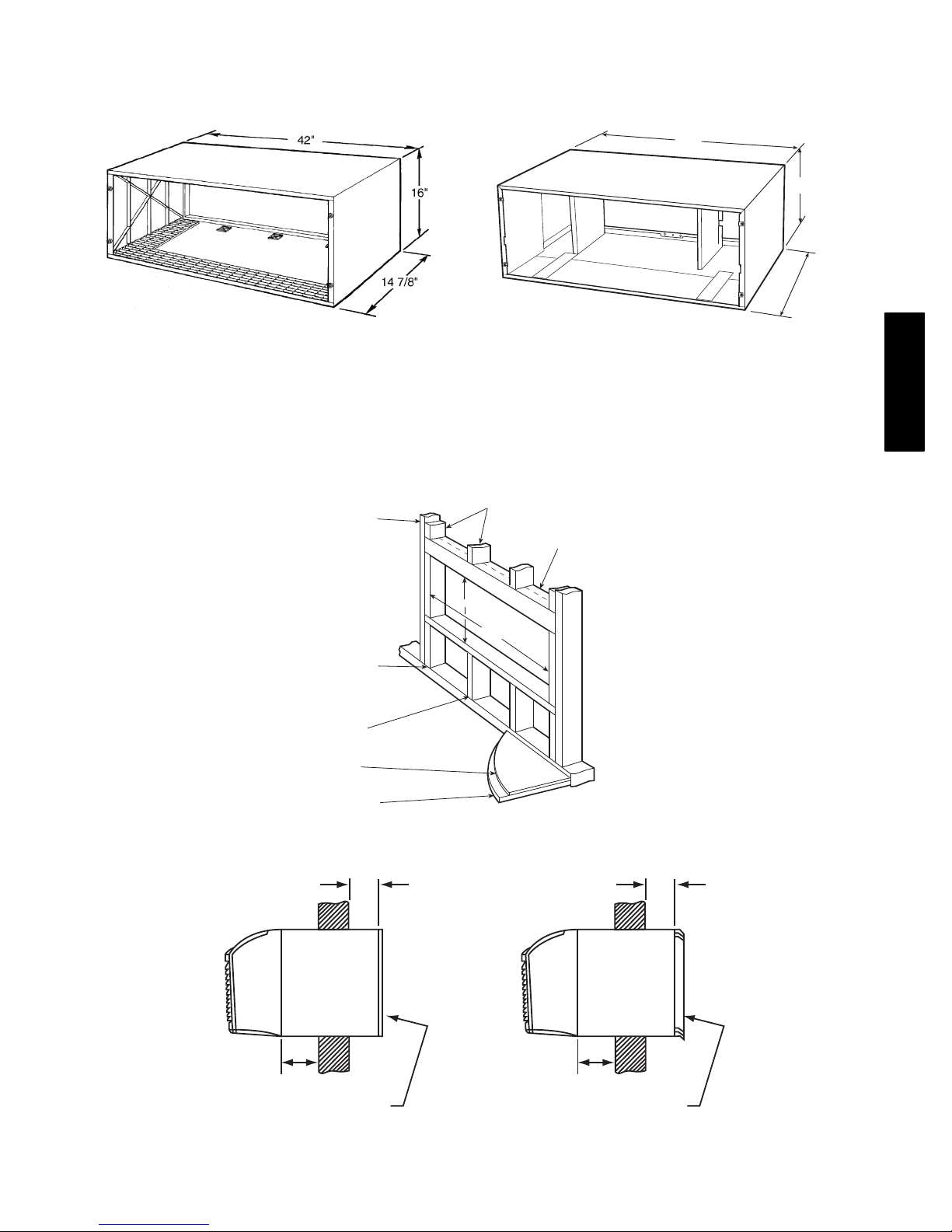
DIMENSIONAL DRAWINGS AND INSTALLATION DA TA -NEW CONSTRUCTION (CONT.)
WALL SLEEVE MOUNTING DIMENSIONS FOR S TANDARD AND ACC ES S ORY GRILLES
42 in.
A07633
Standard Polymer Non-- Insulated Wall Sleeve
Standard Polymer Insulated Wall Sleeve
NOTES (Al l Sleeves):
1. Never i nstall fasteners through bottom of sleeve.
2. Never use rails to level sleeve.
MAIN STUD
Standard and Extended Metal Insulated Wall
Sleeve
JACK STUDS
HEADER- 4’ x 4’ OR
(2) 2’ x 4’ ON EDGE
16 in.
Available in:
14-3/4 in.,
18 in.,
24 in.,
26 in.,
28 in.
A07381
52M
16 1/4”
42 1/8”
JACK STUD
CRIPPLE
FLOOR
SUB-FLOOR
Framing and Minimum Wall Sleeve Opening
5/8" MIN.
(16)
SIDE
5/8" MIN.
A07382
(16)
SIDE
1/2" MINIMUM
STANDARD OUTDOOR GRILLE
1/2" MINIMUM
ARCHITECTURAL GRILLE
STANDARD MOUNT
ALUMINUM OR PLASTIC
Wall Sleeve Mounting (All Models)
25
A07383
Page 26
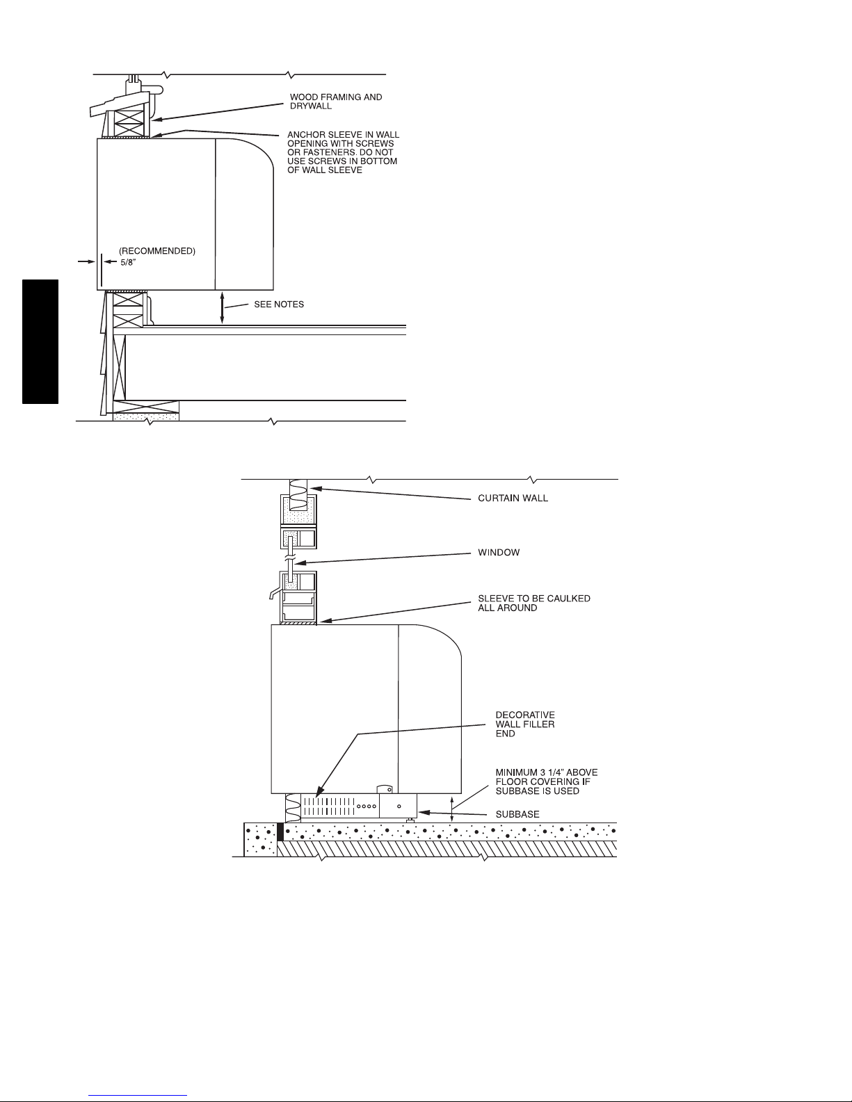
TYPICAL WALL INSTALLATION
52M
Typical Wall Sleeve Installa ti on
NOTES:
1. Sleeve may be flush mounted to floor, but front
panel may have to be notched to accommodate
service cord.
2. If more than 4 in. of sleeve projects into room,
an accessory subbase must be used for support.
3. For walls 2 in. thick or less, an accessory
subbase must be used for support.
4. Caulk around sleeve on both i ndoor and outdoor
sides.
A07384
Typical Curtain Wall Installation (All Models)
A07385
26
Page 27
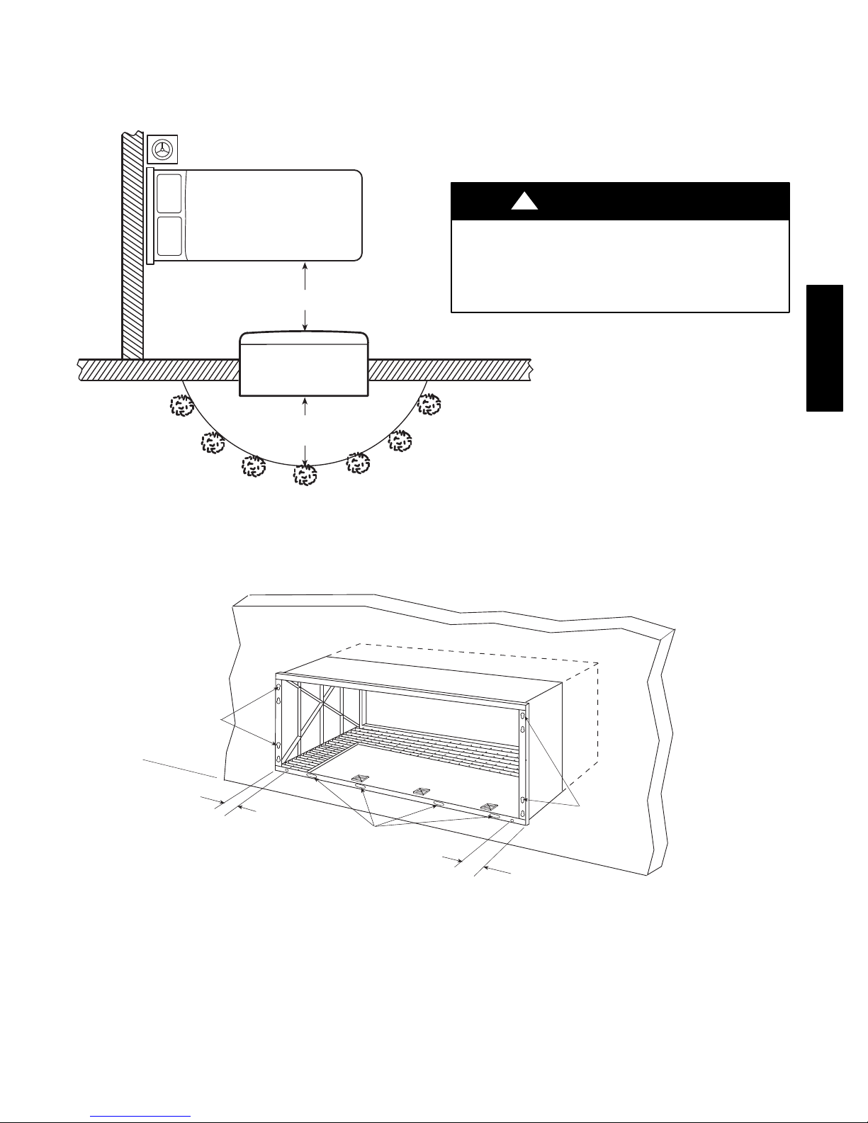
DIMENSIONAL DRAWINGS AND INSTALLATION -NEW CONSTRUCTION (CONT.)
MINIMUM CLEARANCE FOR INDOOR AND OUTDOOR DISCHARGE AIR
!
CAUTION
EQUIPMENT OPERATION HAZARD
Failure to follow this caution may result in equipment
damage or improper operation.
15” MINIMUM DISTANCE FROM
FRONT PANEL TO OBJECTS IN ROOM
36" MINIMUM DISTANCE FROM
SLEEVE TO BUILDING WALLS,
SHRUBS, etc.
Blocking indoor or outdoor discharge air could cause
premature failure of unit.
52M
52M Ind oor and Outdoor Discharge Air
Circulation
OUTDOOR VIEW
GRILLE
MOUNTING
HOLES
WALL SLEEVE
2 3/8”
(60.3)
WALL SLEEVE-(2)
DRAIN LOCATIONS
CONDENSATE
OVERFLOW
HOLES
(OUTSIDE)
Back of Polymer Wall Sleeve
A07386
2 3/8”
(60.3)
GRILLE
MOUNTING
HOLES
A07387
27
Page 28
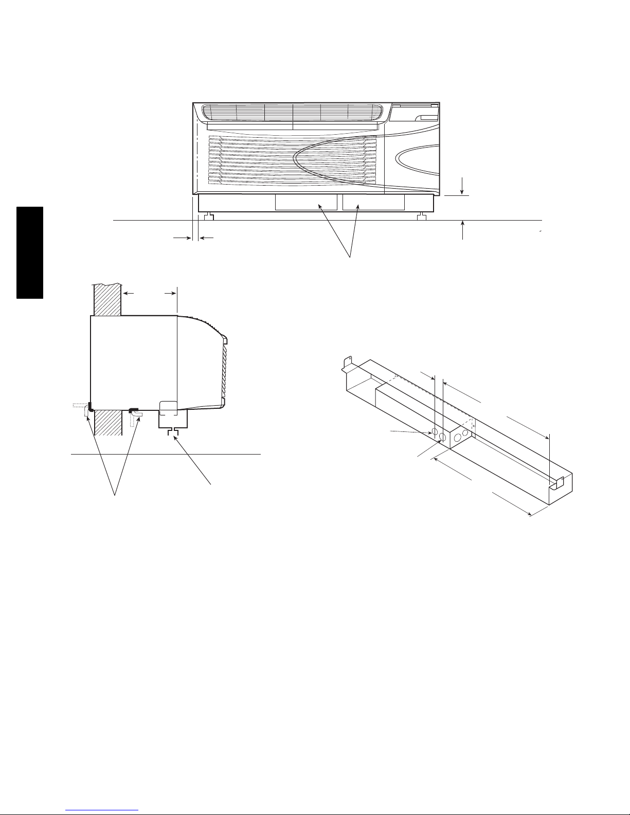
DIMENSIONAL DRAWINGS AND INSTALLATION DA TA -NEW CONSTRUCTION (CONT.)
52M WITH SUBBASE
0’-3 1/4” MIN. (83)
0’-5 1/2” MAX. (140)
0’-0 7/8”
(22)
52M
NOTES:
OUTSIDE
WALL
SEE
NOTES
SIDE
ACCESSORY DRAIN
(EXTERNAL OR INTERNAL)
1. Accessory subbase is required for applications where:
- Wall sleeve extends 4 or more inches into the room.
- Wall thickness is less than 2 inches.
- All 265-v cord-connected applications.
2. For all applications with an accessory subbase:
- Wall sleeve must extend 4 in. minimum into the room and 3
- Subbase height is adjustable from 3
Refer to wall sleeve installation instructions.
SUBBASE ACCESS COVERS
1 9/16”
(39.7)
(3) 7/8” (22.2)
DIA. KNOCKOUTS
(3) 1 1/8” (28.6) DIA.
KNOCKOUTS
SUBBASE LEVELING BOLTS
ELECTRICAL CONNECTIONS
1
1
/
in. minimum to 51/2 in. maximum above floor (including carpeting).
4
/4 in. minimum above the floor.
REAR VIEW
ACCESSORY SUBBASE
19 1/2”
(495.3)
17”
(431.8)
A07389
28
Page 29
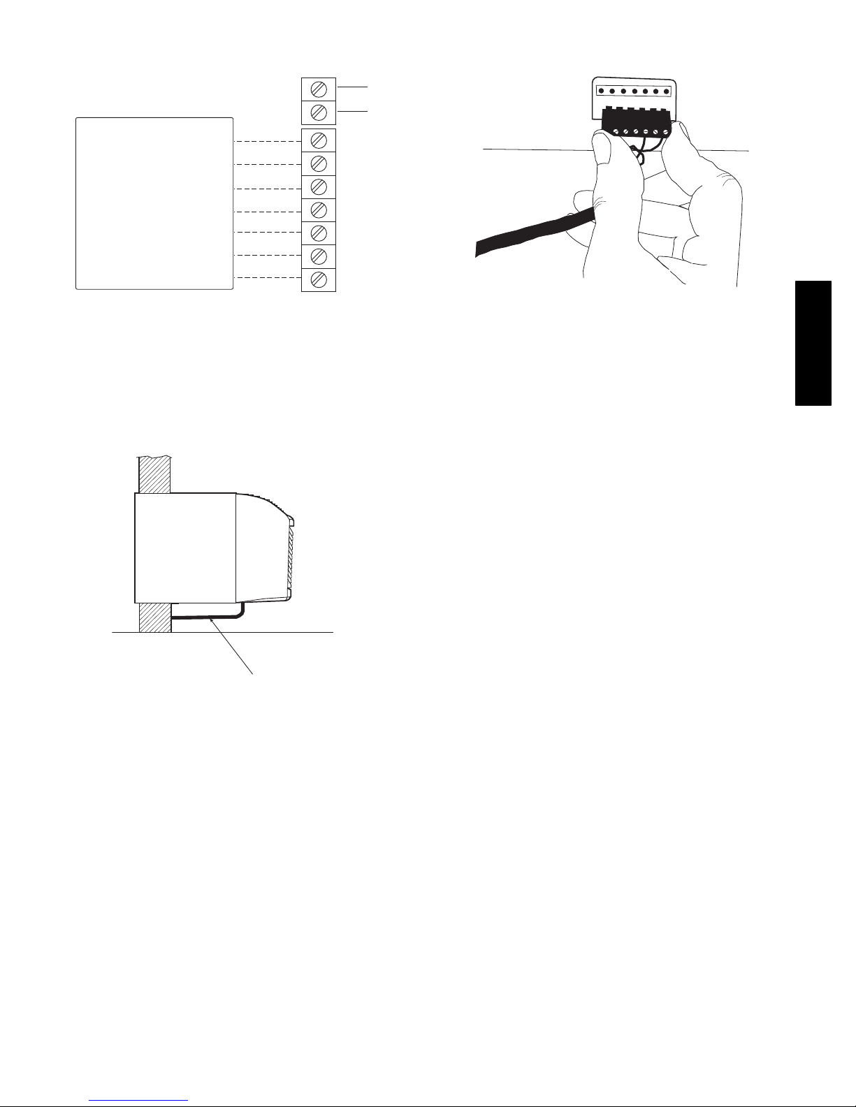
WALL THERMOSTAT CONNECTIONS
Energy
Management
(24VAC in)
Common
R
W
TYPICAL WALL THERMOSTAT
NOTES:
1. Use terminal "O" for heat pump connection only.
2. Terminal "C" (common) is typically only required for digital thermostats.
Control Box Wire T erminal for
Wall Th ermo sta t Models
TERMINAL BLOCK
Y
O
GH
GL
C
See Note 1
See Note 2
A07059
Terminal Connector Removal and Replacement
R W Y O Gh Gl C
A07073
52M
THERMOSTAT WIRE ROUTING
(UNDER SLEEVE, BEHIND FRONT PANEL)
Terminal Wire Routing
NOTE: Thermostat wire is field supplied. Recommended wire gage is 18
to 20 gage solid thermostat wire. Thermostat wire should always be routed
around or under, NEVER through, the wall sleeve. The wire should then
be routed behind the front panel to the easily accessible terminal
connector.
A07074
29
Page 30
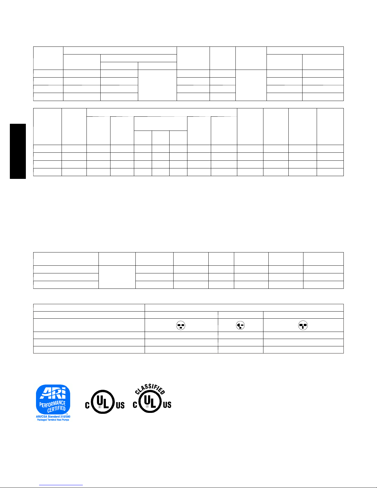
PERFORMANCE AND ELECTRICAL DATA
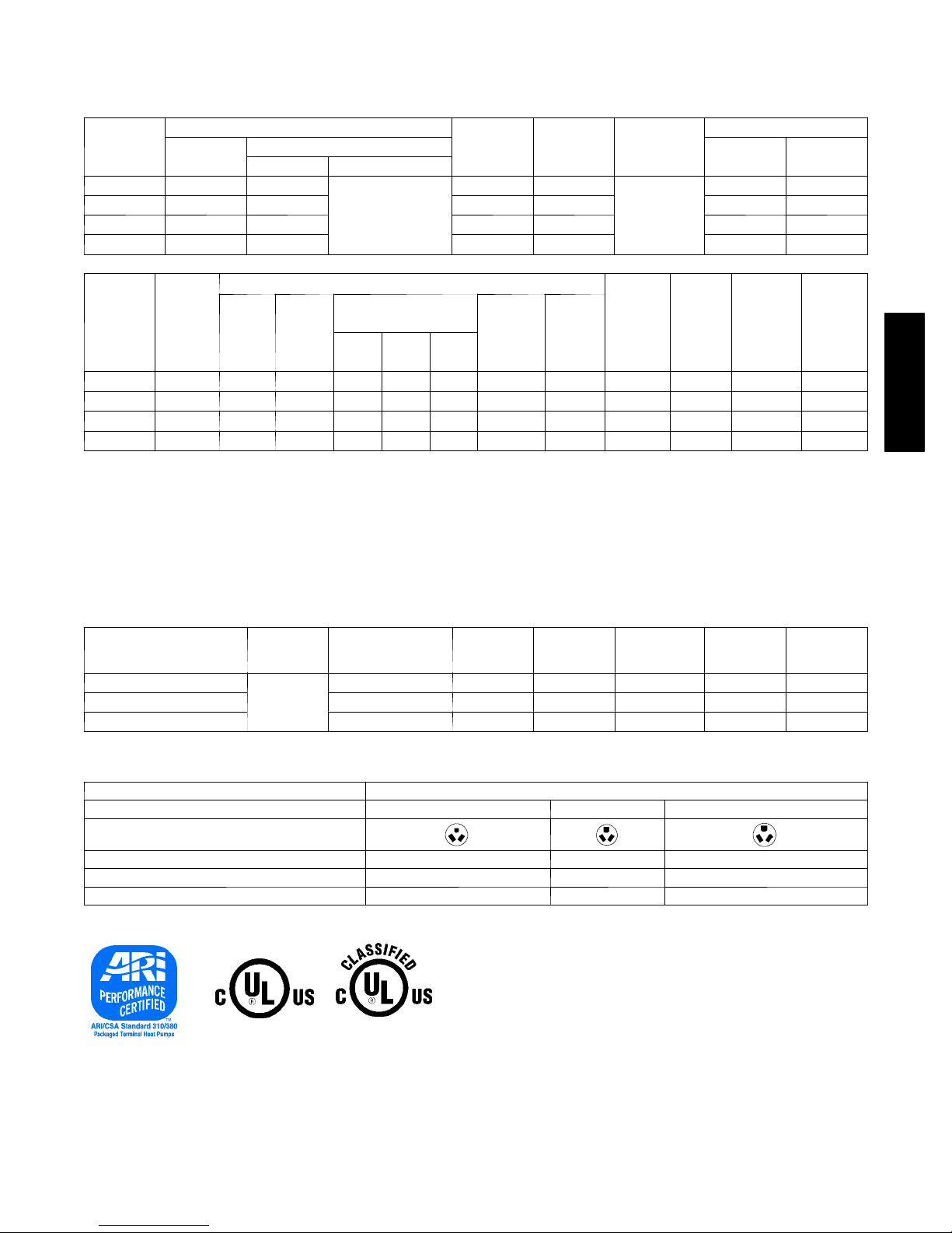
MODEL 52MQ (230/208--1--60)
MODEL
NUMBER
52MQ
U 0 7 --- --- --- 3 --- ---
U 0 9 --- --- --- 3 8800 / 9000 8300 / 8350 10.5 / 10.5 3.4 / 3.3 4.1 / 3.9 840 / 860
U 1 2 --- --- --- 3 12000 / 12000 10700 / 10900 11.1 / 11 .1 3.4 / 3.3 5.1 / 4.8 1080 / 1090
U 1 5 --- --- --- 3 --- --- --- --- --- ---
MODEL
NUMBER
52MQ
U 0 7 --- --- --- 3 --- --- --- --- --- --- --- --- --- --- --- 125
U 0 9 --- --- --- 3 100 0.029 0.2 270 320 350 0.088 0.6 28.9 2.1 0.76 125
52M
U 1 2 --- --- --- 3 100 0.029 0.2 280 320 350 0.088 0.6 36.7 3.7 0.68 140
U 1 5 --- --- --- 3 --- --- --- --- --- --- --- --- --- --- --- 150
LEGEND
EER — Energy Efficiency Ratio
* Rated in accordance with ARI Standard 380-93.
† Coefficient of Performance (COP) at 47 F outdoor a mbient temperature.
} Fan motor indoor CFM (LO/HI) shown for 230-1-60 units.
Cooling
POWER
FACTOR
(%)
CAPACITY
Rev. Cyc. Electic
Indoor
Motor
HP
Indoor
Motor
Full
Load
Amps
Heating
SEE POWER
CORD
SELECTION
GUIDE BELOW
FAN MOTOR
Indoor CFM
Low Med High
EER COP
--- ---
Out-
door
Motor
HP
Outdoor
Motor
Full L oad
Amps
VOLTAGE
RANGE
187 --- 253
R --- 2 2
CHARGE
(OZ)
AMPS WATTS
--- ---
DEHUM.
(Pint/Hr)
SENSIBLE
FACTOR
COOLING
HEAT
APPROX.
CHASSIS
SHIP WT.
(lb)
POWER CORD SELECTION GUIDE
52M PTACs are not individually equipped with a power cord, so one must be ordered separately
based on the voltage and ampeage of your electrical circuit. If the unit is to be plugged into a
receptacle, then a line cord connection kit needs to be selected. If it will be permanently connnected,
a hardwire connection must be used.
Model No. Volt age
PWRCORD--- 230V --- 15A
PWRCORD--- 230V --- 20A 20 amp /250 8556 / 10393 3 2507/ 3045 16.7 20
P W R C O R D --- 2 3 0 --- 3 0 A 30 amp /250 13778 / 16990 5 4037 / 4978 27.1 30
208/230V
RecepTacle
Ty p e
15 amp /250 5631 / 6949 2 1650 / 2036 11.3 15
RECEPTACLE AND FUSE TYPES
UNIT NAMEPLATE VOLTAGE 230/208
OUTLET RATED VOLTS/AMPS 250/15 250/20 250/30
OUTLET BLADE CONFIGU RATION
RECEPTACLE TYPE A B C
NEMA CONFIGURATION 6 --- 1 5 R 6 --- 2 0 R 6 --- 3 0 R
TIMEDEALYFUSEORHACRCIRCUITBREAKER(AMPS) 15 20* 30
LEGEND
HACR --NEMA --- National Electrical Manufacturers Association
* May be used for 15--- amp applications if fused f or 15 amps.
Heating, Air Conditioning, and Refrigeration
Heating
(BTUH)
Heater
(Kw)
Input Power
Current
(Amps)
Branch Circiut
Full A mps
New York City Department of Buildings, Material
and Equipment Acceptance — MEA #-- ---- -- -- --
30
Page 31
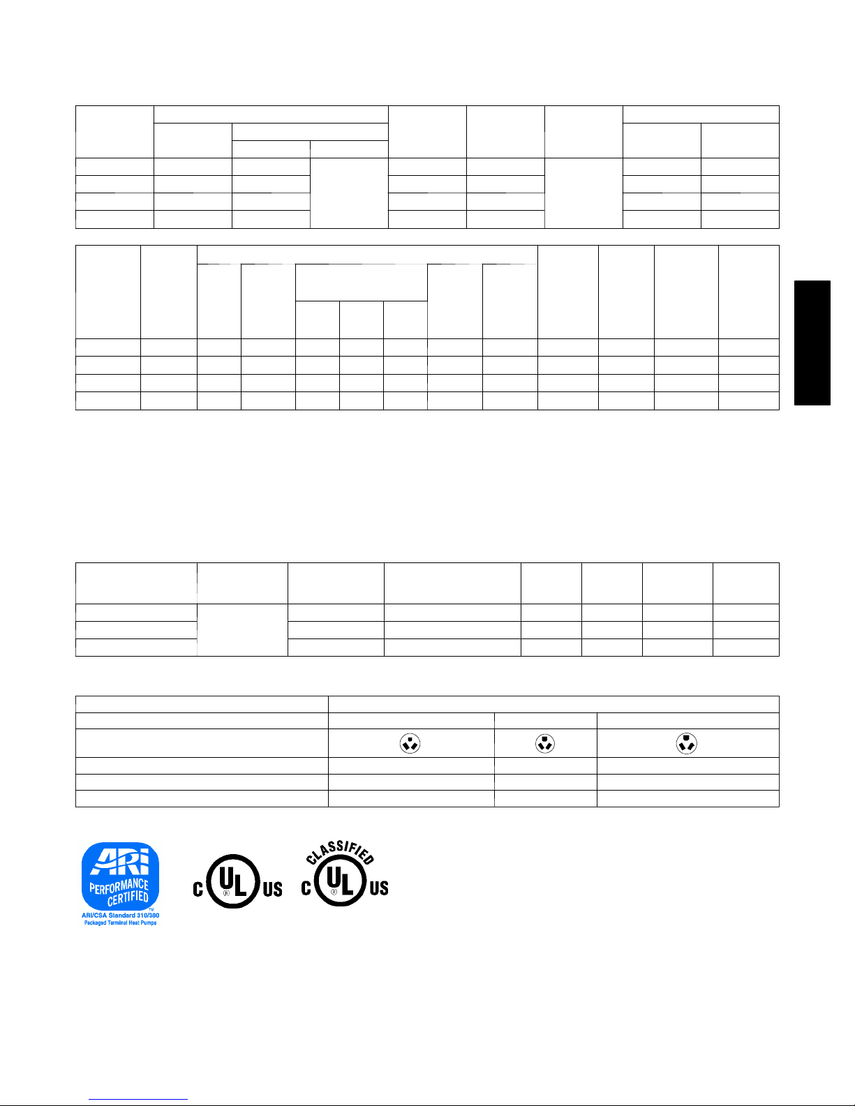
PERFORMANCE AND ELECTRICAL DATA (CONT.)
MODEL 52MQ (265--1-- 60)
MODEL
NUMBER
52MQ
U 0 7 --- --- --- 4 --- ---
U 0 9 --- --- --- 4 9000 8400 10.9 3.5 3.2 825
U 1 2 --- --- --- 4 11,400 10,600 10.8 3 4.2 1050
U 1 5 --- --- --- 4 --- --- --- --- --- ---
MODEL
NUMBER
52MQ
U 0 7 --- --- --- 4 --- --- --- --- --- --- --- --- --- --- --- 125
U 0 9 --- --- --- 4 97 0.029 0.2 275 285 300 0.06 0.4 29.6 2.7 0.7 125
U 1 2 --- --- --- 4 98 0.029 0.2 220 250 290 0.06 0.4 37.4 4.3 0.66 140
U 1 5 --- --- --- 4 --- --- --- --- --- --- --- --- --- --- --- 150
LEGEND
EER — Energy Efficiency Ratio
* Rated in accordance with ARI Standard 380-93.
† Coefficient of Performance (COP) at 47 F outdoor a mbient temperature.
Cooling
POWER
FACTOR
(%)
CAPACITY*
Rev. Cyc. Electic
Indoor
In-
door
Mo-
tor
HP
Fan
Motor
Full
Load
Amps
Heating
SEE POWER
CORD
SELECTION
GUIDE
BELOW
FAN MOTOR
Indoor CFM
Low Med High
EER COP†
--- ---
Outdoor
Motor
HP
Outdoor
Motor
Full
Load
Amps
VOLTAGE
RANGE
239 --- 292
R---22
CHARGE
(OZ)
DEHUM.
(Pint/Hr)
COOLING
AMPS WATTS
--- ---
SENSIBLE
HEAT
FACTOR
APPROX.
CHASSIS
SHIP WT.
(lb)
52M
POWER CORD SELECTION GUIDE
52M PTACs are not individually equipped with a power cord, so one must be ordered separately
based on the voltage and ampeage of your electrical circuit. If the unit is to be plugged into a
receptacle, then a line cord connection kit needs to be selected. If it will be permanently connnected,
a hardwire connection must be used.
Model No. Voltage Receptacle Type Heating (BTUH)
PWRCORD--- 265V --- 15A
PWRCORD--- 265V --- 20A 20 amp /250 10471 3 3068 14.7 20
P W R C O R D --- 2 6 5 --- 3 0 A 30 amp /250 17116 5 5015 23.8 30
NOTE: In compliance with UL, and the National Electrical Code, 265V units installed iwth a power cord require the use use of a 265V electrical subbase.
265V
15 amp /250 6826 2 2000 9.6 15
Heater
(Kw)
Input
Power
Current
(Amps)
RECEPTACLE AND FUSE TYPES
UNIT NAMEPLATE VOLTAGE 265
OUTLET RATED VOLTS/AMPS 277/15 277/20 277/30
OUTLET BLADE CONFIGU RATION
RECEPTACLE TYPE A B C
NEMA CONFIGURATION 7 --- 1 5 R 7 --- 2 0 R 7 --- 3 0 R
TIMEDEALYFUSEORHACRCIRCUITBREAKER(AMPS) 15 20 30
LEGEND
HACR --- Heating, Air Conditioning, and Refrigeration
NEMA --- National Electrical Manufacturers Association
Branch
Circiut
Full A mps
New York City Department of Buildings, Material
and Equipment Acceptance — MEA #-- ---- -- -- --
31
Page 32
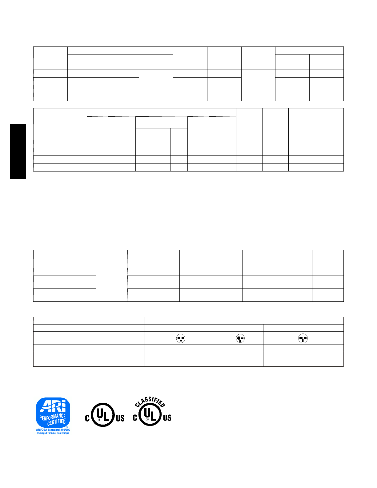
PERFORMANCE AND ELECTRICAL DATA (CONT.)
MODEL 52ME (230/208--1--60)
MODEL
NUMBER
52ME
U 0 7 --- --- --- 3 --- ---
U 0 9 --- --- --- 3 8800 / 9000 --- 11.4 / 11.4 --- 3.9 / 3.7 770 / 790
U 1 2 --- --- --- 3 12,000 / 12,100 --- 11.4 / 11.5 --- 5/ 4.7 1060 / 1070
U 1 5 --- --- --- 3 --- --- --- --- --- ---
Cooling
CAPACITY
Heating
Rev. Cyc. Electic
SEE POWER
CORD
SELECTION
GUIDE
BELOW
EER COP
--- ---
VOLTAGE
RANGE
187 --- 253
COOLING
AMPS WATTS
--- ---
FAN MOTOR
MODEL
NUMBER
52ME
U 0 7 --- --- --- 3 --- --- --- --- --- --- --- --- --- --- --- 125
U 0 9 --- --- --- 3 98 0.029 0.2 265 290 330 0.088 0.6 28.9 2.9 0.73 125
52M
U 1 2 --- --- --- 3 100 0.029 0.2 280 300 320 0.088 0.6 36.0 3.9 0.71 140
U 1 5 --- --- --- 3 --- --- --- --- --- --- --- --- --- --- --- 150
EER — Energy Efficiency Ratio
* Rated in accordance with ARI Standard 380-93.
† Fan motor indoor CFM (LO/HI) shown for 230-1-60 units.
LEGEND
POWER
FACTOR
(%)
Indoor
Motor
HP
Indoor
Motor
Full L oad
Amps
Indoor CFM
Low Med High
Out-
door
Motor
HP
Outdoor
Motor
Full L oad
Amps
R --- 2 2
CHARGE
(OZ)
DEHUM.
(Pint/Hr)
SENSIBLE
HEAT
FACTOR
POWER CORD SELECTION GUIDE
52M PTACs are not individually equipped with a power cord, so one must be ordered separately
based on the voltage and ampeage of your electrical circuit. If the unit is to be plugged into a
receptacle, then a line cord connection kit needs to be selected. If it will be permanently connnected,
a hardwire connection must be used.
Model No. Vo ltage Receptacle Type
PWRCORD--- 230V --- 15A
PWRCORD--- 230V --- 20A 20 amp /250
P W R C O R D --- 2 3 0 --- 3 0 A 30 amp /250
208/230V
15 amp /250 5631 / 6949 2 1650 / 2036 11.3 15
Heating
(BTUH)
8556 /
10393
13778 /
16990
Heater
(Kw)
3 2507/ 3045 17.3 20
5 4037 / 4978 27.1 30
Input Power
Current
(Amps)
APPROX.
CHASSIS
SHIP WT.
(lb)
Branch Cir-
ciut Full
Amps
RECEPTACLE AND FUSE TYPES
UNIT NAMEPLATE VOLTAGE 230/208
OUTLET RATED VOLTS/AMPS 250/15 250/20 250/30
OUTLET BLADE CONFIGU RATION
RECEPTACLE TYPE A B C
NEMA CONFIGURATION 6 --- 1 5 R 6 --- 2 0 R 6 --- 3 0 R
TIMEDEALYFUSEORHACRCIRCUITBREAKER(AMPS) 15 20* 30
LEGEND
HACR --- Heating, Air Conditioning, and Refrigeration
NEMA --- National Electrical Manufacturers Association
* May be used for 15--- amp applications if fused f or 15 amps.
New York City Department of Buildings, Material
and Equipment Acceptance — MEA #-- ---- -- -- --
32
Page 33
PERFORMANCE AND ELECTRICAL DATA (CONT.)
MODEL 52ME (265--1--60)
MODEL
NUMBER
52ME
U 0 7 --- --- --- 4 --- ---
U 0 9 --- --- --- 4 9100 --- 11.7 --- 3.3 790
U 1 2 --- --- --- 4 12100 --- 11.5 --- 4.35 1050
U 1 5 --- --- --- 4 --- --- --- --- --- ---
MODEL
NUMBER
52MQ
U 0 7 --- --- --- 4 --- --- --- --- --- --- --- --- --- --- --- 125
U 0 9 --- --- --- 4 98 0.029 0.2 265 300 320 0.06 0.4 28.9 2.7 0.72 125
U 1 2 --- --- --- 4 100 0.029 0.2 280 310 345 0.06 0.4 36.7 4.3 0.69 140
U 1 5 --- --- --- 4 --- --- --- --- --- --- --- --- --- --- --- 150
LEGEND
EER — Energy Efficiency Ratio
* Rated in accordance with ARI Standard 310-93.
Cooling
POWER
FACT OR
(%)
Indoor
Motor
CAPACITY
Heating
Rev. Cyc. Electic
SEE POWER CORD
SELECTION GUIDE
Indoor
Fan
Motor
HP
Full
Load
Amps
Low Med High
BELOW
FAN MOTOR
Indoor CFM
EER COP
--- ---
Outdoor
Outdoor
Motor HP
Motor
Full
Load
Amps
VOLTAGE
RANGE
239 --- 292
R --- 2 2
CHARGE
(OZ)
DEHUM.
(Pint/Hr)
COOLING
AMPS WATTS
--- ---
SENSIBLE
HEAT
FACT OR
APPROX.
CHASSIS
SHIP WT.
(lb)
52M
POWER CORD SELECTION GUIDE
52M PTACs are not individually equipped with a power cord, so one must be ordered separately
based on the voltage and ampeage of your electrical circuit. If the unit is to be plugged into a
receptacle, then a line cord connection kit needs to be selected. If it will be permanently connnected,
a hardwire connection must be used.
Model No. Voltag e Receptacle Type
PWRCORD--- 265V --- 15A
PWRCORD--- 265V --- 20A 20 amp /250 10471 3 3068 14.7 20
P W R C O R D --- 2 6 5 --- 3 0 A 30 amp /250 17116 5 5015 23.8 30
NOTE: In compliance with UL, and the National Electrical Code, 265V units installed iwth a power cord require the use use of a 265V electrical subbase.
265V
15 amp /250 6826 2 2000 9.6 15
Heating
(BTUH)
Heater (Kw) Input Power
Current
(Amps)
RECEPTACLE AND FUSE TYPES
UNIT NAMEPLATE VOLTAGE 265
OUTLET RATED VOLTS/AMPS 277/15 277/20 277/30
OUTLET BLADE CONFIGU RATION
RECEPTACLE TYPE A B C
NEMA CONFIGURATION 7 --- 1 5 R 7 --- 2 0 R 7 --- 3 0 R
TIMEDEALYFUSEORHACRCIRCUITBREAKER(AMPS) 15 20 30
LEGEND
HACR --NEMA --- National Electrical Manufacturers Association
Heating, Air Conditioning, and Refrigeration
Branch Cir-
ciut Full
Amps
New York City Department of Buildings, Material
and Equipment Acceptance — MEA #-- ---- -- -- --
33
Page 34
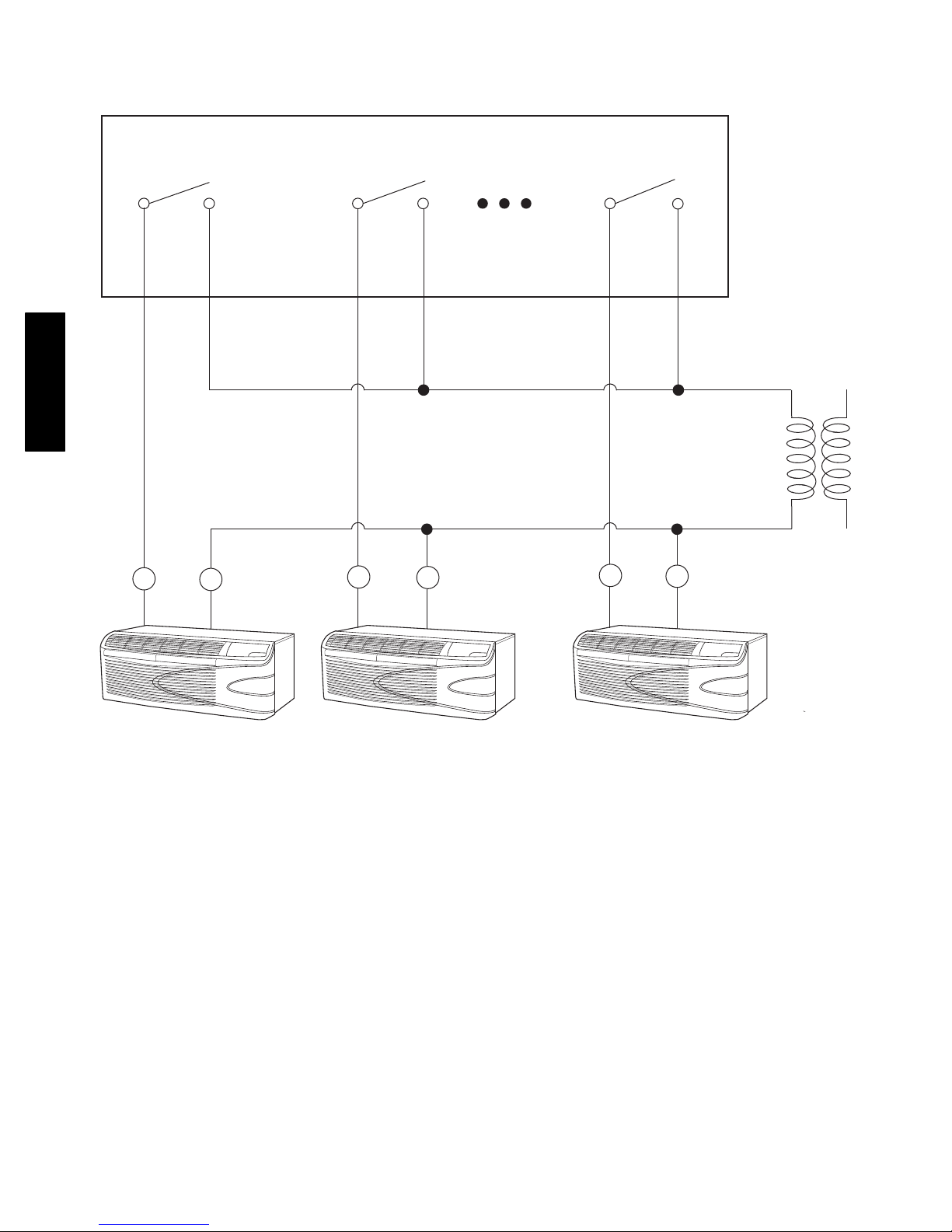
TYPICAL WIRING SCHEMATIC FOR ENERGY
MANAGEMENT INTERFACE
FRONT DESK SWITCH PANEL
ROOM 100 ROOM 101 ROOM N
52M
FIELD-SUPPLIED
24-V
TRANSFORMER
(SEE NOTE 1)
B
PTAC #1
W
B
PTAC #2
LEGEND
AW G ó American Wire Gage
BóBlack
PTAC ó Packaged Terminal Air Conditioner
WóWhite
NOTES:
1. To size transformer, use the following equation:
Quantity of PTAC units x 12 va = Transformer Size (va)
Example: 110 PTAC Units x 12 va = 1320 va Transformer
2. Following are recommended wire sizes:
AWG WIRE SIZE NO. MAXIMUM LENGTH (ft)
24 400
22 600
20 900
18 1500
16 2000
W
B
W
PTAC #N
A07390
34
Page 35
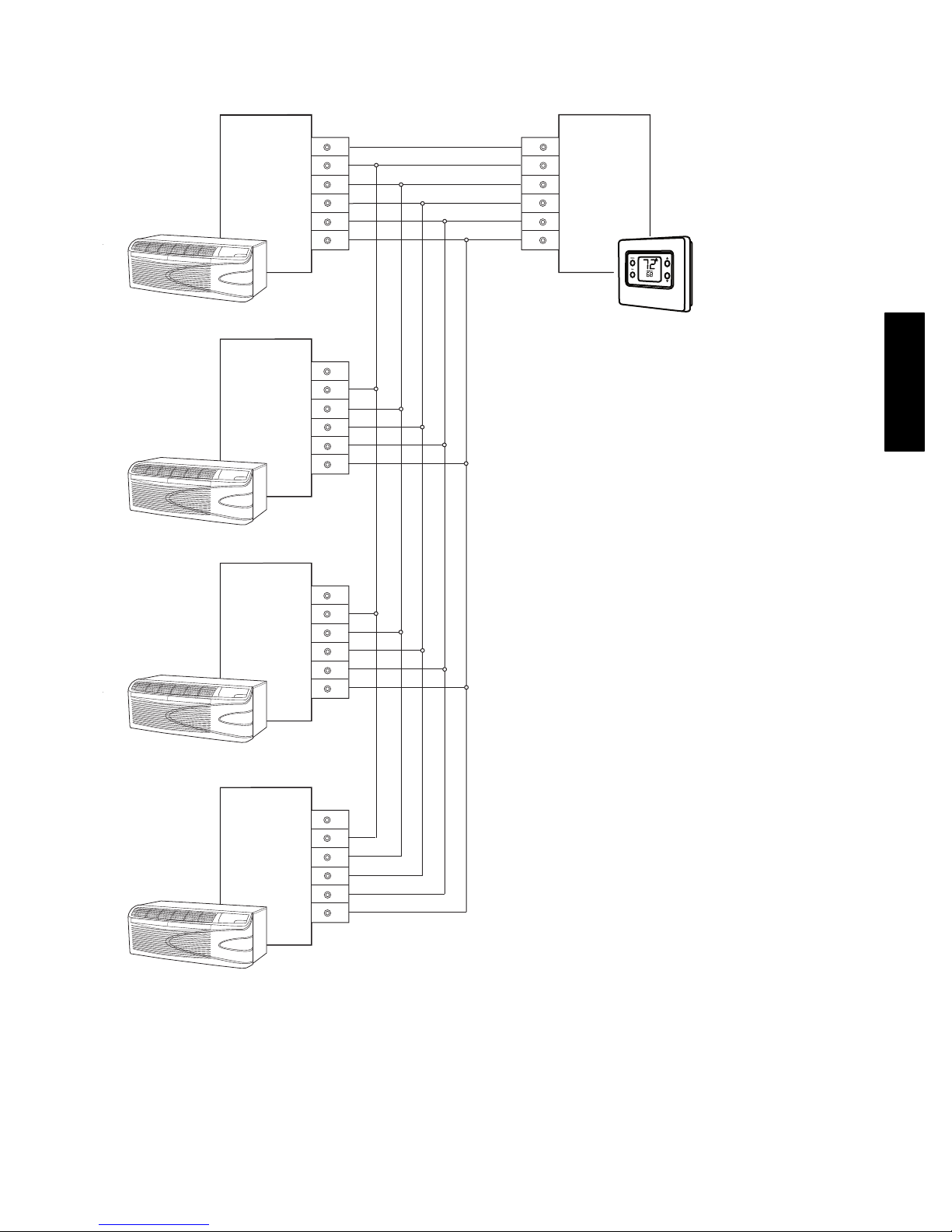
TYPICAL WIRING SCHEMATIC FOR MULTIPLE PTAC UNITS
CONNECTED TO A SINGLE WALL THERMOSTAT
MASTER
PTAC
UNIT 1
UNIT 2
R
Y
W
G
O
C
R
Y
W
G
O
C
R
Y
W
G
O
C
R
Y
W
G
O
C
T’STAT
52M
UNIT 3
R
Y
W
G
O
C
1. Do not daisy chain R (24 VAC).
2. Maximum of 4 PTAC units can be connected to one single wall
thermostat.
3. Wall thermostat wire is field-supplied and should be 18 to
20 gage solid thermostat wire.
A07391
35
Page 36

PACKAGED TERMINAL COOLING UNIT
WITH HEAT PUMP OR ELECTRIC HEATING
HVAC Guide Specifications
Size Range:
Cooling: 6,900 to 15,000 Btuh
Heating: 6, 000 to 13,400 Btuh
Heat Pump:6,400 to 17,000 Btuh Electric
Carrier Model Numbers:
52ME Performance Series, Cool i ng wit h Electric
Heat
52MQ P erform an ce Series, Heat Pump with Electric
Heat
Part 1 — System Description
Packaged Terminal Air Conditioners shall be of the
52M
sizes and capacities as shown on the contract drawing
schedule and in the specifications.
System shall be tested to insure no water infiltration
into the room, when tested at eight inches of rain per
hour with 55 mph wind.
The complete system shall consistof the following:
A. Packaged Terminal Heat Pump or Heat/Cool
Chassis : See section 2 -- Chassis Description
B. Power Cord OR Hardwire Kit shall provide the
power connection to the unit.
C. Insulated Polymer Wall Sleeve shall provide
excellent thermal insulation, be textured to hide
scratches and prevent shine, will have superior
outdoor noise absorption and shall be corrosion
free for the life of the product. The Wall Sleeve
must have dimensions of 42” width x 16“ height x
14--7/8” depth and be shipped with a rear weather
barrier installed.
D. Wall Sleeve Molding shall trim the wall sleeve to
the existing wall, to hide wall imperfections and
irregularities due to the sleeve opening.
E. Outdoor Polymer Louvered Grille shall resist
corrosion, breakage and match the color specified
on drawing schedule and specifications.
F. Subbase will support the wall sleeve when it
extends into the room more than 4 inches.
Subbase must come from the factory
pre--assembled, with a built in receptacle (size as
specified on drawing schedule and
specifications).
Part 2 — Chassis Description
2.1 General:
The chassis shall be a factory--assembled,
single-- piece heating and/or cooling unit, that is
simple to install and operate. Just slide the chassis
into a wall sleeve, plug it into an outlet, and operate
after installation. The chassis dimensions shall not
exceed 42” wide and 16“ h i gh wit h room cabin et in
place. The ch ass i s shall cons i st of the fol l owi n g
functional sections and components:
A. Certifications:
System shall be approved and certified by UL &
UL, Canada. Chassis capacity and efficiency
performance shall be certified in accordance with
ARI standard 310/380. Chassis shall meet
ASHRAE Standard 90.1 for minimum energy
efficiency.
B. Operating Characteristics:
Chassis shall be capable of starting and running at
115_F ambient outdoor temperature per maximum
load criteria of ARI Standard 310/380.
C. Electrical:
The accessory power cord or hardwire kit for the
unit will be ordered separately. The power cord
accessory will be 58 inches for 208/230v models
or 15 inches for 265v models. The Hardwire kit
accessory will provide 36 inches of flexible
conduit. The chassis current draw shall be
specified on the chassis nameplate and match
electrical requirements specified on the Contract
drawing schedule and specifications.
The power cord plug configuration shall conform
to NEMA standards and the rating shall support
the current draw of the electric resistance heater.
For 265v installations, UL codes require the use of
an electrical equipped subbase for power cord
usage or hardwire conduit for non--corded
installations.
D. Safeties:
Compressor shall have automatic reset, over
temperature and over current protection. The fan
motors shall have an inherent, automatic reset
over temperature protection. The electric heater
shall have two over temperature protectors.
36
Page 37

E. Air Flow System:
For superior sound and comfort, t he airflow
system shall consist of two, direct--drive
permanently lubricated fan motors. The outdoor
fan m otor will be single speed, with a dynamically
balanced, corrosion resistant, polymer multiblade
axial flow design, with integrated slinger ring. The
indoor fan motor will be three speeds, with a
dynamically balanced, polymer, tangential blower
wheel, to assure uniform air distribution and
optimal sound. Both Fan Motors shall be of an
enclosed design to reduce the effects of moisture
and corrosion.
F. Compressor & Refrigerant:
The rotary--type Compressor shall be fully
hermetic with internal and external vibration
isolation. The refrigeration system will be sealed
and contain a full refrigerant charge (R--22).
G. Coils:
Condenser and evaporator coils to be constructed
of high--efficiency copper tubing, necessary to
achieve EER and COP rating, as specified on the
chassis name plate.
H. Factory--Installed Electric Heater:
The factory--installed, open coil type, electric
heater is standard in heat/cool and heat pump
chassis. The electric heater shall contain both an
automatic reset and a one--shot over temperature
protection device. The heating capacity of the
electric heater shall be as identified on the
Contract drawing schedule and in the
specifications.
I. Controls:
All standard models shall be equipped with
electronics, for added features and improved
reliability of the unit.
GUARD enabled or disabled, WALL
THERMOSTAT enabled or disabled,
EMERGENCY HEAT (for heatpumps), and 4
optional SETPOINT LIMIT selections.
Fan cycle configuration switches, will allow
continuous fan operation for maximum comfort or
cycle operation for maximum energy savings.
Settings can be different for both heating and
cooling operations, for maximum comfort and
efficiency.
All standard models shall have Temperature
Limiting control, with four easy to configure
settings. Temperature limiting allows a room
temperature range to be set, to avoid extreme
temperature settings, to maximize energy savings.
Emergency Heat Switch (Heat Pump Models
Only) shall disable the compressor in heating
mode and only allow the use of electric heat
during heating cycles. The Emergency Heat switch
is active at all outdoor ambient temperatures.
All units shall be capable of interfacing to a wall
thermostat; have a blank out label to cover the
control panel for wall thermostat applications;
and have a removable wall thermostat terminal
block, to simplify field wiring. No additional
field--installed kits shall be required.
Wall thermostat interface shall provide two fan
speed selections to maximize comfort.
Compatible with 2 wire central desk control
systems.
52M
The chassis shall have an easy to operate, user
friendly, electronic display with simple to push,
large digital buttons. All will be easily accessible
and covered by a hinged door.
The mode selection control shall consist of OFF,
FAN ONLY, HEAT or COOL operations. There
will be 3 optional Fan Speed Options, LOW,
MED or HIGH. The temperature selection will be
controlled by color coded, simple to operate
warmer and cooler buttons. The upper and lower
setpoint temperature limits, can be easily
configured.
All models shall have a configuration dipswitch,
easily accessible for the maintenance person,
optimal comfort settings, CONTINUOUS or
CYCLE fan mode in HEATING, CONTINUOUS
or CYCLE fan mode in COOLING, FREEZE
Freeze Guard to automatically activate the electric
heater and indoor fan to warm the room, to
prevent damage from freezing temperatures.
Freeze guard will be active as long as there is
power supplied to the unit. Unit shall have the
ability to disable Freeze guard, if needed.
Unit shall have the option to display temperature
in _For_C.
Unit will have memory; in case power is lost, unit
will return to all previous settings.
Unit will have a random compressor restart after a
power outage, to prevent power surges due to
many units turning on at the same time.
Room temperature sensing shall use a Solid state
thermostat control.
37
Page 38

J. Front Panel (supplied with chassis): Front
panel shall be constructed of a polymer material to
resist breakage and corrosion. It shall have a front
louvered surface with integrated control door and
air filters. The air filters shall be easily accessible
without removing the front panel from the chassis.
K. Air Filters: The chassis shall contain air filters,
with a minimum of 40% arrestance per ASHRAE
Standard 52.1. Two easily accessible front access
supply air filters, shall be interchangeable,
washable and permanent type. The vent filter shall
be a one--piece, removable and washable type
filter.
L. Bi--Directional Discharge Grille: Bi--directional
polymer discharge grille shall resist corrosion and
breakage. It shall be easily set to direct air at 40
degrees from horizontal or 80 degrees from
52M
horizontal. This non--metallic discharge grille
shall be cool to the touch during the heating cycle.
M.Ventilation: The chassis shall have a manual
adjustable fresh air vent with a concealed manual
control. The vent control shall allow a maximum
of up to 65 CFM of fresh air to be drawn into the
room when the indoor fan is operating and the
door is open. The ventilation air can be increased
to approximately 95 CFM by adding the Booster
Ventilation accessory kit (see section S.13)
N. High Efficiency Condensate Removal System:
The chassis shall have a condensate removal
system consisting of a condensate suction port, to
draw and atomize condensate, and a slinger ring
integrated in the outdoor fan, to disperse
condensate onto the condenser coil to be
evaporated.
O. 2--piece Condenser Coil Shroud: The condenser
coil shroud shall be two pieces, to allow easy
access to service and maintain components in the
condenser section.
P. Accessories:
1. Power Cord (PN: PWRCORD--xxxV--xxA)
accessory, is required for all corded
applications.
2. Hardwire kit (PN: 52M--HDWR--KIT--xxA)
shall be required if an accessory power cord is
not used. The hardwire kit provides a permanent
connection to the unit and shall have 36 inches
of flexible steel conduit and a plug--in connector
for easy connect/disconnect.
3. Insulated Polymer Wall Sleeve (PN:
SLEEVE--INSUL--1PK) shall be made from a
molded polymer, with factory installed
Styrofoam insulation and a minimum
flammability rating of UL94--5V. The sleeve
surface shall be textured to prevent shine and
hide scratches.
4. Deep Wall Metal Wall Sleeve (up to 28--in.)
(PN: SLEEVE--EXTxx--1PK) shall be a one-piece, extended wall sleeve, with factory
installed insulation and deep wall baffles
integrated.
5. Sleeve Molding (PN: SLEEVE--MOLDING)
shall trim the wall sleeve to the existing wall to
hide wall joints and irregularities due to the
sleeve opening.
6. Architectural Grille
GRILLE--ALU--xxxxx)
(PN:GRILLE --PLA--xxxxx or
shall be polymeric for long
durable life or painted aluminum for a superior
color match to the building.
7. Subbase (PN: SUBBASE--xxxV--xxA) shall be
pre--assembled from the factory and UL listed.
Subbase options include:
— Non- electrical subbase: The
non--electrical subbase shall be
pre--assembled and provides
mechanical support and requires no
wiring.
— Electrical subbase: The electrical
subbase shall be pre--assembled with
factory--installed electrical junction
box containing a receptacle for corded
units.
8. Drain kit (PN: DRAIN--KIT--4PK): This
universal drain kit shall be used internally or
externally to route excess condensate to a
drainage system. It can be field --installed on any
Carrier wall sleeve. The drain kit shall be
attached to the exterior right or left side of the
wall sleeve for external draining or may be
mounted to the bottom of t he wall sleeve for
internal draining. The drain kit shall include
both a straight tube and a 90_ bend tube.
9. Wall Thermostats
PTACSTAT--NP--HP-- A)
(PN: PTACSTAT--NP--HC--A &
The digital wall
thermostat shall have a large LCD display with
backlighting, operate with 24VAC, be
non--programmable, easy to use and provide
maximum guest comfort.
10. Ventilation Booster
(PN: 52M-- PWRVENT--DOOR):
The ventilation booster shall provide
approximately 95 CFM of outdoor air for
ventilation into the room. The kit shall have an
automatically door that opens when the booster
fan is on and closes when the booster fan is off.
38
Page 39

3.0 DELIVERY, STORAGE, AND HANDLING
The packaging of the chassis shall be sufficient to
protect the chassis from damage during shipment via
an enclosed truck. Chassis must also be able to
withstand an impact force of 10 g’s and a random
continuous force of 1g, during shipping.
Chassis, wall sleeves, and grilles shall be shipped in
separate cartons. Universal handling instructions
shall be defined and visible on the carton, from front,
back and sides.
Chassis shall be capable of withstanding
temperatures from --40_F to 155_F,at5to95
percent RH, non--condensing, during shipment and
storage, without component failure.
52M
39
Page 40
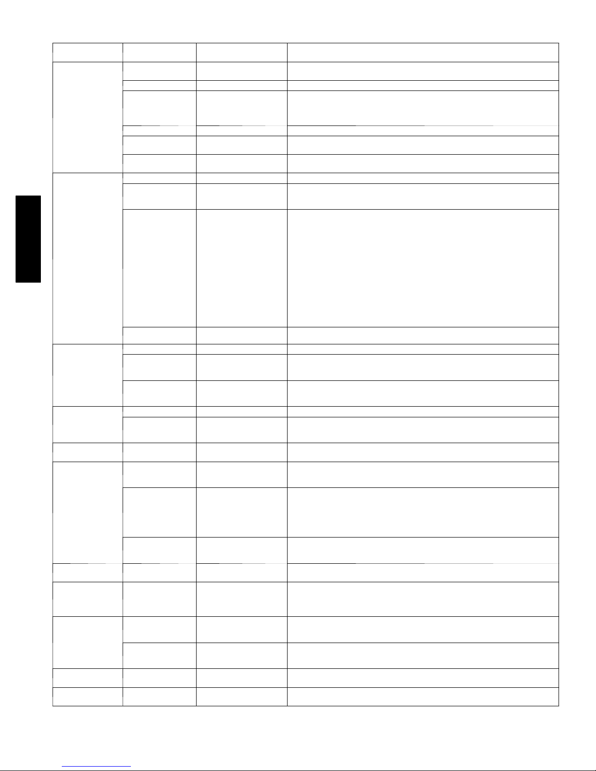
ACCESSORIES
ACCESSORY
Wall Sleeves
52M
Exterior Grilles*
Subbase
Subbase Field --Installed Kits
Sleeve Support 52C,P --- 29SI LEVELING--- LEGS
Electrical
Connections
Condensate
Drain Kit
Wall Thermostats N/A
Wall Thermostat
Locking Covers
Replacement
Filters
Power Vent
Retrofit Kit
* Custom colors are also available.
FORM
NUMBER
52S---48SI
52S---50SI SLEEVE ---STEEL --- 1PK Insulated Metal Wall Sleeve, 1 per pack
52S---49SI
N/A SLEEVE---MOLDING Molding kit to trim the wall sleeve to the wall
52C,P---26SI F R --- S L E E V E --- E X T
52C,P---28SI C M --- S L E E V E --- E X T
52S---59SI G R I L L E --- A L U --- S T AM P Stamped Aluminum Exterior Grille, Clear Finish
52S---65SI
52S---60SI
52C,P---31SI B A F F L E --- K I T --- 1 P K
52C,P---1SI S U B B A S E --- N O N --- E L E C N o n --- e l e c t r i c a l S u b b a s e
52C,P---2SI
52C,P---17SI
52C,P---4SI SUBBASE --- SWITCH Field--- Installed Switch kit for an electrical subbase
52C,P---5SI
5 2 M --- H D W R --K I T --- 0 1
I I K --- P W R C O R D --- 0 1
52C,P---19SI
52S---53SI D R A I N --- K I T --- 4 P K
N/A T S T A T --- C O V E R --- 6 X 7
N/A T S T A T --- C O V E R --- 7 X 1 0
N/A 5 2 M --- A I R F I LT --- 1 0 P K Replacement air filters in package of 10
N/A 5 2 M --- P W R V E N T --- D O OR Power vent with automatic door that opens a n d closes when the f an turns on and off.
PAR T N U MB ER DESCRIPTION
WAL L --- S L E E V E --- 1 P K
S L E E V E --- I N S U L --- 1 P K
S L E E V E --- E X T 1 8 --- 1 P K
S L E E V E --- E X T 2 4 --- 1 P K
S L E E V E --- E X T 2 6 --- 1 P K
S L E E V E --- E X T 2 8 --- 1 P K
G R I L L E --- P L A --- B R O W N
G R I L L E --- P L A --- B E I G E
G R I L L E --- P L A --- A L P I N
G R I L L E --- A L U --- C L E A R Aluminum Architectural Exterior Grille, Clear Finish
G R I L L E --- A L U --- W H I T E Aluminum Architectural Exterior Grille, White
G R I L L E --- A L U --- B R O N Z Aluminum Architectural Exterior Grille, Light Bronze
G R I L L E --- A L U --- M B R N Z Aluminum Architectural Exterior Grille, Medium Bronze
G R I L L E --- A L U --- B R O W N Aluminum Architectural Exterior Grille, Brown (Dark Bronze)
G R I L L E --- A L U --- B E I G E Aluminum Architectural Exterior Grille, Beige
G R I L L E --- A L U --- AL P I N Aluminum Architectural Exterior Grille, Alpine (matches Carrier Wall Sleeve)
G R I L L E --- A L U --- P E A C H Aluminum Architectural Exterior Grille, Peach
G R I L L E --- A L U --- M E L O N Aluminum Architectural Exterior Grille, Melon
G R I L L E --- A L U --- L G R E Y Aluminum Architectural Exterior Grille, Light Grey
G R I L L E --- A L U --- S G R E Y Aluminum Architectural Exterior Grille, Slate Gray
G R I L L E --- A L U --- R D B R K Al uminu m Architectu ral Exterior Grille, Red Brick
G R I L L E --- A L U --- B L U E Aluminum Architectural Exterior Grille, Blue
G R I L L E --- A L U --- G R E E N Aluminum Architectural Exterior Grille, Green
SUBBASE---230V---15A
SUBBASE---230V---20A
SUBBASE---230V---30A
SUBBASE---265V---15A
SUBBASE---265V---20A
SUBBASE---265V---30A
SUBBASE---FUSE --- 15A
SUBBASE---FUSE --- 20A
SUBBASE---FUSE --- 30A
5 2 M --- H D W R --- K I T --- 1 5 A
5 2 M --- H D W R --- K I T --- 2 0 A
5 2 M --- H D W R --- K I T --- 3 0 A
PWRCORD--- 230V --- 15A
PWRCORD--- 230V --- 20A
PWRCORD--- 230V --- 30A
PWRCORD--- 265V --- 15A
PWRCORD--- 265V --- 20A
PWRCORD--- 265V --- 30A
52M ---CONINT ---15A---4
52M ---CONINT ---20A---4
52M ---CONINT ---30A---4
P T A C S T AT --- N P --- H C --- A
P T A C S T AT --- N P --- H P --- A
T C --- P A C --- 0 1
T C --- P H P --- 0 1
Non--- Insulated Polymer Wall Sleeve, 1 per pack
Insulated Polymer Wall Sleeve, 1 per pack
Extended Metal Wall Sleeve for Deep Wall Applications (18 in. deep), 1 per pack
Extended Metal Wall Sleeve for Deep Wall Applications (24 in. deep), 1 per pack
Extended Metal Wall Sleeve for Deep Wall Applications (26 in. deep), 1 per pack
Extended Metal Wall Sleeve for Deep Wall Applications (28 in. deep), 1 per pack
Friedrich wall sleeve extension to retrofit Carrier PTAC unit into Friedrich 11 ---1/2”
deep (T Series) wall sleeve. 1 per pack
Climate Master Wall Sleeve extension to retrofit Carrier PTAC unit into Climate Master
12---1/2” deep wall sleeve. 1 per pack
Brown Polymer Architectural Rear Grille,
Beige Polymer Architectural Rear Grille,
Alpine (matches Carrier Wall Sleeve)
Ensures good air seal and prevents air recirculation when Carrier sleeve is used with
a no n --- C a r r ie r gr i l l e .
Electrical subbase with factory --- installed 208/230V, 15 amp receptacle
Electrical subbase with factory --- installed 208/230V, 20 amp receptacle
Electrical subbase with factory --- installed 208/230V, 30 amp receptacle
Electrical subbase with factory --- installed 265V, 15 amp receptacle
Electrical subbase with factory --- installed 265V, 20 amp receptacle
Electrical subbase with factory --- installed 265V, 30 amp receptacle
Field--- Installed Fuse Kit (15 amp) for electrical subbase
Field--- Installed Fuse Kit (20 amp) for electrical subbase
Field--- Installed Fuse Kit (30 amp) for electrical subbase
Attaches to wall sleeve for accurate and adjustable leveling and support for units
without a subbase
Permanent power connection to the unit (includes 36” of flexible conduit and unit--mounted connector, 230/208V and 265V) 1 per pack
Requied accessory power cord.
Order cord based on voltage and amperage of electrical circuit being used to power
PTAC.
Interface kit for field---supplied conduit to provide permanent power connection
(230/208V an d 265V) to the unit. Kit includes Molex connector for easy connect/disconnect. 4 per pack
Attaches to wall sleeve for controlled internal or external disposal of condensate---4
per pack
Comfort Series Non---Programmable Thermostat (heat/cool)
Comfort Series Non--- Programmable Thermostat (HP)
Comfort Series Programmable Thermostat ( AC)
Comfort Series Programmable Thermostat (HP)
Clear plastic locking thermostat cover prevents unauthorized access to thermostat.
Cover for use with non ---programmable and el ectro ---mechanical thermostats.
Outside dimensions: 6 --- 1/2” X 7 ---1/2” X 2 --- 15/16”. 1 per pack
Clear plastic locking thermostat cover prevents unauthorized access to thermostat.
Coverforusewithprogrammablethermostats.
Outside dimensions: 7 --- 1/4” X 9 ---3/4” X 3 --- 3/8”. 1 per pack
40
Page 41

TYPICAL WARRANTY
52M
This is the responsibility of the installer.
any other damages due to the inadequacy or interruption of electrical services.
unauthorized alteration, improper servicing or operation.
environment, or other conditions beyond the control of CARRIER.
EXCEPTION TO CORROSIVE ENVIRONMENT EXCLUSION IN ABOVE
PARAGRAPH – Packed terminal units (52 Series) built with corrosion protection
are exempt from the exclusion – “Corrosive Environment.” The unit model
number is identified on the nameplate with CP suffix.
or designated by CARRIER and which are specifically covered under this
warranty.
normal maintenance as outlined in the owner’s manual.
installation.
1. CLEANING REQUIRED PRIOR TO WARRANTY REPAIR.
2. Standard maintenance, cleaning or damage resulting from failure to perform
3. Instruction on methods of control and use of air conditioning unit after initial
4. Damage or repairs needed as consequence of faulty installation or application.
5. Failure to start due to voltage conditions, blown fuses, open circuit breakers or
6. Damage or repairs needed as consequence of any misapplication, abuse,
7. Damage as a result of floods, winds, fires, lightning, accidents, corrosive
CARRIER WILL NOT BE RESPONSIBLE FOR:
8. Reimbursement for replacement parts or repair services which are not supplied
Canada.
9. CARRIER products installed outside the continental U.S.A., Alaska, Hawaii, and
10. Shipping damage or damage as a result of transporting the unit. This is the
responsibility of the selling dealer or the authorized Room Air Conditioner service
station.
11. ANY SPECIAL, INDIRECT OR CONSEQUENTIAL PROPERTY OR
COMMERCIAL DAMAGE OF ANY NATURE WHATSOEVER. Some states do
not allow the exclusion or limitation of incidental or consequential damages, so
the above limitation or exclusion may not apply to you.
12. Warranty coverage of accessory items (wall thermostats, wall sleeves, etc.)
NOTE: Service and Maintenance items excluded in this warranty may be covered by a
separate service agreement through the seller at time of purchase.
This warranty gives you specific legal rights, and you may also have other rights which vary from state to state.
Carrier
Packaged Terminal
Air Conditioner Limited Warranty
____________________________________________________________________
FIRST YEAR PARTS AND LABOR LIMITED WARRANTY -- During the first year after
purchase, CARRIER will, through its authorized independent servicing dealer or service
stations*, and free of charge to the user or subsequent users, repair or replace any parts
that fail due to defect in material or workmanship. The replacement part can be a new or
remanufactured part as provided at CARRIER’S sole option.
EXTENDED FOUR-YEAR PARTS AND LABOR LIMITED WARRANTY ON SEALED
REFRIGERATION SYSTEM ONLY – During the second through fifth years after date of
original purchase, CARRIER will, through its authorized servicing dealers and service
stations* and free of charge to the end user or subsequent users, repair or replace the
compressor, condenser, evaporator or connecting tubing if it failed due to defect in material
or workmanship. This includes system refrigeration charge. The replacement part can be
new or a remanufactured part at CARRIER’S sole option.
EXTENDED FOUR-YEAR PARTS ONLY LIMITED WARANTY ON NON-SEALED
REFRIGERATION SYSTEM ONLY – During the second through fifth years after date of
original purchase, Carrier will, through its authorized servicing dealers and service stations
and free of charge to the end user or subsequent users, repair or replace any non-sealed
system part (motor, solenoid, thermistor, thermostat, relays, switch, capacitor, overload,
41
drain valve, bulb heater, fan, stator) if failed due to defect in material or workmanship. The
replacement part can be new or a remanufactured part at CARRIER’S sole option. THIS
LIMITED WARRANTY DOES NOT INCLUDE LABOR, user is responsible for labor,
including cost of diagnosis of problem, removal and transportation of the air conditioner to
and from the service center, and reinstallation charges necessary to accomplish repair.
LIMITATION OF WARRANTIES – ALL IMPLIED WARRANTIES (INCLUDING IMPLIED
*Authorized independent dealers or service stations are registered with Carrier through its distributor organization.
WARRANTIES OF MERCHANTABILITY AND FITNESS FOR PARTICULAR USE OR
PURPOSE) ARE HEREBY LIMITED IN DURATION TO THE PERIOD FOR WHICH EACH
LIMITED WARRANTY IS GIVEN AND APPLIES. SOME STATES DO NOT ALLOW
LIMITATIONS ON HOW LONG AN IMPLIED WARRANTY LASTS, SO THE ABOVE
LIMITATION MAY NOT APPLY TO YOU. THE EXPRESSED WARRANTIES MADE IN
THIS WARRANTY ARE EXCLUSIVE AND MAY NOT BE ALTERED, ENLARGED, OR
CHANGED BY ANY DISTRIBUTOR, DEALER, OR OTHER PERSON WHATSOEVER. ALL WORK UNDER THE TERMS OF THIS WARRANTY SHALL BE PERFORMED
DURING NORMAL WORKING HOURS. ALL REPLACEMENT PARTS, WHETHER NEW
OR REMANUFACTURED, ASSUME AS THEIR WARRANTY PERIOD ONLY THE
REMAINING TIME PERIOD OF THIS WARRANTY.
Catalog Number: 49004DP58 Edition Date: 08/07
Page 42

52M
can give you his name or you can consult your yellow pages.
STEPS 2 AND 3.
3. CONTACT THE CARRIER DISTRIBUTOR SERVING YOUR AREA. Your dealer
4. CONTACT CARRIER IF A SATISFACTORY SOLUTION IS NOT REACHED IN
IF YOUR AIR CONDITIONER DOES NOT WORK, FOLLOW THESE STEPS IN ORDER:
Carrier Corporation
Consumer Relations Department
Carrier Parkway, P.O. Box 4808
Syracuse, New York 13221
Telephone: 1-800-894-6449
air conditioner is plugged in firmly in an appropriate receptacle, checking the fuse
or circuit breaker and ensuring its replacement or resetting, if necessary, and
rereading the instruction book to ensure that all controls are set properly. By
doing this you can save money. Many unnecessary service calls result in the
serviceman doing what the owner can do for him or herself.
CENTER HE RECOMMENDS. They have been set up to handle the great
majority of all possible service problems. The quickest, surest and best way to
get your air conditioner back in service is to use this step before proceeding
further.
1. CHECK THE THINGS YOU CAN DO YOURSELF. These include being sure the
Carrier Corporation
____________________________________________________________________
Copyright 2007 Carrier Corp. S 7310 W. Morris St. S Indianapolis, IN 46231
Manufacturer reserves the right to change, at any time, specifications and designs without notice and without obligations.
2. CONTACT YOUR DEALER OR THE CARRIER AUTHORIZED SERVICE
Printed in U.S.A. Edition D ate: 09/07
Catalog Number: 49004DP58 Edition Date: 08/07
Catalog No. 52M --- 1PD
Replaces: New
42
 Loading...