

Carrier 50ZH024, 50ZH030, 50ZH036, 50ZH042, 50ZH048 Installation, Start-up And Service Instructions Manual
...Page 1
50ZH024-060
Packaged Heat Pump Units
Installation, Start-Up and Service Instructions
NOTE: Read the entire instruction manual before starting the
installation.
TABLE OF CONTENTS
SAFETY CONSIDERATIONS.....................................................1
INTRODUCTION..........................................................................2
RECEIVING AND INSTALLATION..........................................2
Check Equipment......................................................................2
IDENTIFY UNIT................................................................2
INSPECT SHIPMENT........................................................2
Provide Unit Support................................................................2
SLAB MOUNT ...................................................................2
GROUND MOUNT ............................................................2
Provide Clearances....................................................................2
Place Unit..................................................................................2
Select and Install Ductwork .....................................................2
INSTALL FLANGES FOR DUCTWORK CONNEC-
TIONS (50ZH060 ONLY)..................................................6
CONVERTING HORIZONTAL DISCHARGE UNITS TO
DOWNFLOW (VERTICAL) DISCHARGE......................6
Provide for Condensate Disposal.............................................6
Install Electrical Connections...................................................7
HIGH-VOLTAGE CONNECTIONS..................................7
ROUTING POWER LEADS INTO UNIT........................8
CONNECTING GROUND LEAD TO UNIT
GROUND ............................................................................8
ROUTING CONTROL POWER WIRES..........................8
ACCESSORY ELECTRIC HEAT WIRING .....................8
SPECIAL PROCEDURES FOR 208-V OPERATION .....8
PRE-START-UP ............................................................................9
START-UP.....................................................................................9
Check for Refrigerant Leaks..................................................10
LOCATE AND REPAIR REFRIGERANT LEAKS AND
CHARGE THE UNIT AS FOLLOWS: ...........................10
Start-Up Cooling Section and Make Adjustments ................10
CHECKING COOLING CONTROL OPERATION .......10
COMPRESSOR ROTATION ...........................................10
Refrigerant Charge..................................................................10
NO CHARGE....................................................................10
LOW CHARGE COOLING .............................................10
TO USE THE COOLING CHARGING CHART............10
HEATING MODE CHARGE...........................................11
Indoor Airflow and Airflow Adjustments..............................11
FOR 208/230-V.................................................................12
FOR 460-V MOTORS......................................................12
Unit Controls...........................................................................12
HIGH-PRESSURE RELIEF VALVE...............................12
LOSS OF CHARGE SWITCH.........................................12
COMPRESSOR OVERLOAD..........................................12
Sequence of Operation............................................................12
FAN OPERATION............................................................12
COOLING..........................................................................14
HEAT PUMP HEATING..................................................14
DEFROST..........................................................................15
ELECTRIC RESISTANCE HEATING............................15
MAINTENANCE.........................................................................15
Air Filter..................................................................................16
Unit Top Removal (Outdoor-Coil Side)................................16
Indoor Blower and Motor.......................................................16
Outdoor Coil, Indoor Coil, and Condensate Drain Pan........16
Outdoor Fan............................................................................17
Electrical Controls and Wiring...............................................18
Refrigerant Circuit..................................................................18
Indoor Airflow........................................................................18
Metering Devices....................................................................18
Lubrication..............................................................................18
Liquid Line Strainer................................................................18
High Flow Valves...................................................................19
TROUBLESHOOTING...............................................................22
START-UPCHECKLIST............................................................23
NOTE TO INSTALLER—Before installation, READ THESE
INSTRUCTIONS CAREFULLY AND COMPLETELY. Also,
make sure the User’s Manual and Replacement Guide are left with
the unit after installation.
SAFETY CONSIDERATIONS
Installation and servicing of air-conditioning equipment can be
hazardous due to system pressure and electrical components. Only
trained and qualified workers should install, repair, or service
air-conditioning equipment.
Untrained workers can perform basic maintenance functions of
cleaning coils and filters. All other operations should be performed
by trained service people. When working on air-conditioning
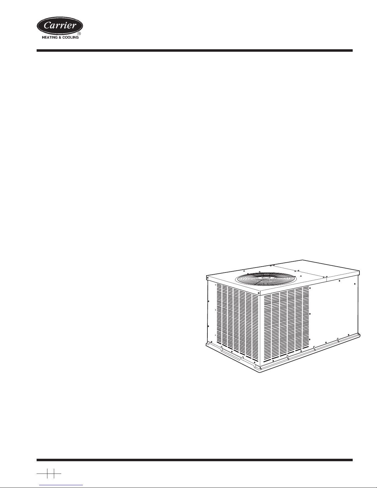
Fig. 1—Unit 50ZH
C00155
Visit www.carrier.com
Manufacturer reserves the right to discontinue, or change at any time, specifications or designs without notice and without incurring obligations.
Book 1 4
Tab 6 8
PC 101 Catalog No. 535-00080 Printed in U.S.A. Form 50ZH-5SI Pg 1 7-03 Replaces: 50ZH-4SI
Page 2
equipment, pay attention to precautions in the literature, tags, and
labels attached to the unit, and other safety precautions that may
apply.
Follow all safety codes. Wear safety glasses and work gloves. Use
quenching cloth for unbrazing operations. Have fire extinguisher
available for all brazing operations.
Before performing service or maintenance operations on
system, turn off main power to unit and install lockout tag.
Turn off accessory heater power switch if applicable. Electrical shock can cause serious injury or death.
Recognize safety information. This is the safety-alert symbol .
When you see this symbol in instructions or manuals, be alert to
the potential for personal injury.
Understand the signal words DANGER, WARNING, CAUTION,
and NOTE. These words are used with the safety-alert symbol.
DANGER identifies the most serious hazards which will result in
severe personal injury or death. WARNING signifies a hazard
which could result in personal injury or death. CAUTION is used
to identify unsafe practices which would result in minor personal
injury or product and property damage. NOTE is used to highlight
suggestions which will result in enhanced installation, reliability,
or operation.
These instructions cover minimum requirements and conform to
existing national standards and safety codes. In some instances,
these instructions exceed certain local codes and ordinances,
especially those that may not have kept up with changing residential construction practices. We require these instructions as a
minimum for a safe installation.
INTRODUCTION
50ZH heat pump units are fully self-contained and designed for
outdoor installation (See Fig. 1). As shown in Fig. 2-4, units are
shipped in a horizontal-discharge configuration for installation on
a ground-level slab. All units can be field-converted to downflow
discharge configurations for rooftop applications with a fieldsupplied plenum.
RECEIVING AND INSTALLATION
Step 1—Check Equipment
IDENTIFY UNIT
The unit model number and serial number are stamped on the unit
identification plate. Check this information against shipping papers. Verify that unit voltage and amperage listed on unit rating
plate agree with power supplied for equipment.
INSPECT SHIPMENT
Inspect for shipping damage while unit is still on shipping pallet.
If unit appears to be damaged or is torn loose from its securing
points, have it examined by transportation inspectors before
removal. Forward claim papers directly to transportation company.
Manufacturer is not responsible for any damage incurred in transit.
Check all items against shipping list. Immediately notify the
nearest Carrier Air Conditioning office if any item is missing.
To prevent loss or damage, leave all parts in original packages
until installation.
Step 2—Provide Unit Support
SLAB MOUNT
Place the unit on a rigid, level surface, suitable to support the unit
weight. A concrete pad or a suitable fiberglass mounting pad is
recommended. The flat surface should extend approximately 2-in.
beyond the unit casing on the 2 sides. The duct connection side and
condensate drain connection sides should be flush with the edge of
the flat surface.
A 6-in. wide gravel apron should be used around the flat surface to
prevent airflow blockage by grass or shrubs. Do not secure the unit
to the flat surface except where required by local codes.
The unit should be level to within 1/4 inch. This is necessary for
the unit drain to function properly.
GROUND MOUNT
The unit may also be installed directly on the ground if local codes
permit. Place unit on level ground prepared with gravel for
condensate discharge.
Step 3—Provide Clearances
The required minimum service clearances and clearances to
combustibles are shown in Fig. 2-4. Adequate ventilation and
outdoor coil air must be provided.
The outdoor fan pulls air through the outdoor coil and discharges
it through the fan on the top cover. Be sure that the fan discharge
does not recirculate to the outdoor coil. Do not locate the unit in
either a corner or under an overhead obstruction. The minimum
clearance under a partial overhang (such as a normal house
overhang) is 48 in. above the unit top. The maximum horizontal
extension of a partial overhang must not exceed 48 inches.
Do not place the unit where water, ice, or snow from an overhang
or roof will damage or flood the unit. The unit may be installed on
wood flooring or on Class A, B, or C roof covering materials.
Do not restrict outdoor coil airflow. An air restriction at either
the outdoor-air inlet or the fan discharge can be harmful to
compressor life.
Step 4—Place Unit
Unit can be moved with the rigging holds provided in the unit base.
Refer to Table 1 for operating weights. Use extreme caution to
prevent damage when moving the unit. Unit must remain in an
upright position during all moving operations. The unit must be
level with in 1/4” for proper condensate drainage; the ground-level
pad must be level before setting the unit in place. When a
field-fabricated support is used, be sure that the support is level
and that it properly supports the unit.
Step 5—Select and Install Ductwork
The design and installation of the duct system must be in
accordance with:
• the standards of the NFPA (National Fire Protection Association) for installation of nonresidence-type air conditioning and
ventilating systems
• NFPA90A or residence-type, NFPA90B; and/or local codes
and residence-type, NFPA 90B
• and/or local codes and ordinances
Select and size ductwork, supply-air registers and return-air grilles
according to ASHRAE (American Society of Heating, Refrigeration, and Air Conditioning Engineers) recommendations.
Use the duct flanges provided on the supply- and return-air
openings on the side of the unit. See Fig. 2-4 for connection sizes
and locations. The 14-in. round duct collars (size 024-048 units)
are shipped inside the unit attached to the indoor blower. They are
field-installed and must be removed from the indoor cavity prior to
start-up, even if they are not used for installation.
2
Page 3
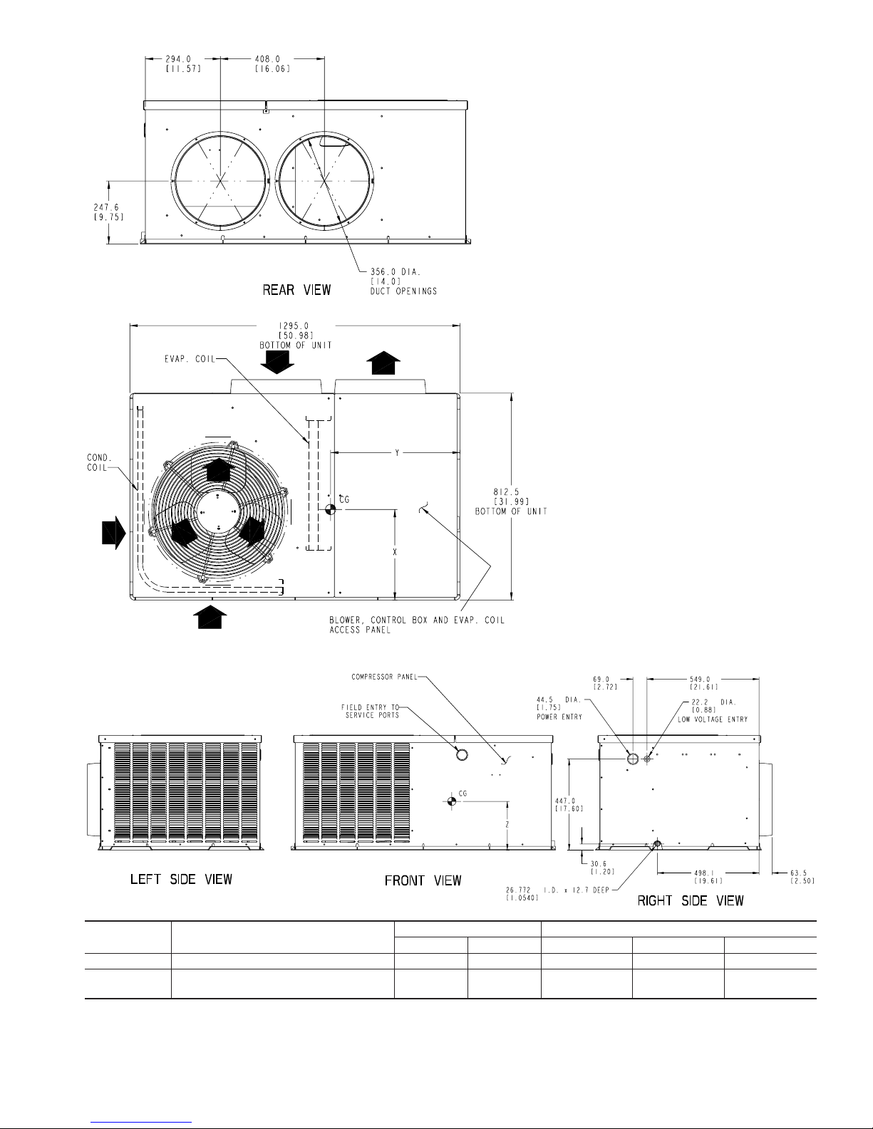
Fig. 2—Unit Base Dimensions, 50ZH024-030
UNIT ELECTRICAL CHARACTERISTICS
UNIT WEIGHT CENTER OF GRAVITY IN. (MM)
lb kg X Y Z
50ZH024 208/230-1-60 232 106 14.0 (356) 19.0 (483) 12.0 (305)
50ZH030
208/230-1-60,
208/230–3–60
254 116 14.0 (356) 19.0 (483) 12.0 (305)
C00156
REQUIRED CLEARANCE FOR OPERATION AND SERVICING
INCHES [mm]
CONDENSER . COIL ACCESS SIDE..............................................30.00 [762.0]
POWER ENTRY SIDE....................................................................30.00 [762.0]
(EXCEPT FOR NEC REQUIREMENTS)
UNIT TOP.......................................................................................48.00 [1219.2]
SIDE OPPOSITE DUCTS ..............................................................30.00 [762.0]
LEGEND
NEC – National Electrical Code
NOTES:
1. Clearances must be maintained to prevent recirculation of air from outdoor-
fan discharge, with the exception of the condenser coil (36.00 in [914.0 mm]. A
removable fence or barricade requires no clearance.
2. Dimensions are in inches. Dimensions in [ ] are in millimeters.
REQUIRED CLEARANCE TO COMBUSTIBLE MATL.
INCHES [mm]
TOP OF UNIT.........................................................................................0
DUCT SIDE OF UNIT.............................................................................0
SIDE OPPOSITE DUCTS ......................................................................0
BOTTOM OF UNIT.................................................................................0
NEC. REQUIRED CLEARANCES.
INCHES [mm]
BETWEEN UNITS, POWER ENTRY SIDE....................................42.00 [1066.8]
UNIT AND UNGROUNDED SURFACES, POWER ENTRY SIDE.36.00 [914.0]
UNIT AND BLOCK OR CONCRETE WALLS AND OTHER
GROUNDED SURFACES, POWER ENTRY SIDE.........................42.00 [1066.8]
3
Page 4
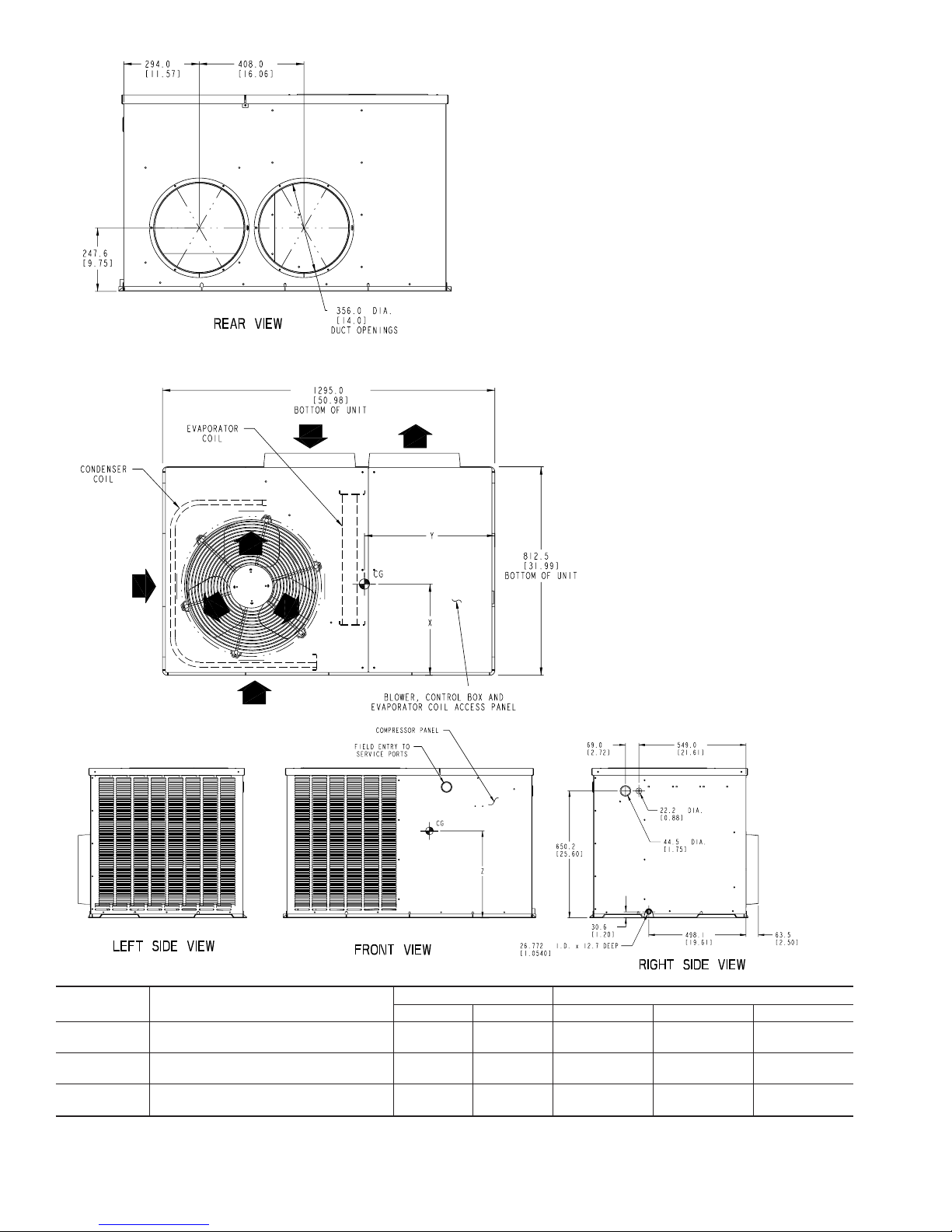
Fig. 3—Unit Base Dimensions, 50ZH036–048
UNIT ELECTRICAL CHARACTERISTICS
UNIT WEIGHT CENTER OF GRAVITY IN. (MM)
lb kg X Y Z
50ZH036
208/230-1-60, 208/230-3-60,
460–3–60
277 126 14.0 (356) 19.0 (483) 15.0 (381)
50ZH042
208/230-1-60, 208/230-3-60,
460–3–60
295 134 14.0 (356) 19.0 (483) 15.0 (381)
50ZH048
208/230-1-60, 208/230-3-60,
460–3–60
328 149 14.0 (356) 19.0 (483) 15.0 (381)
C00003
REQUIRED CLEARANCE FOR OPERATION AND SERVICING
INCHES [mm]
CONDENSER . COIL ACCESS SIDE.............................................. 30.00 [762.0]
POWER ENTRY SIDE....................................................................30.00 [762.0]
(EXCEPT FOR NEC REQUIREMENTS)
UNIT TOP.......................................................................................48.00 [1219.2]
SIDE OPPOSITE DUCTS ..............................................................30.00 [762.0]
LEGEND
NEC – National Electrical Code
NOTES:
1. Clearances must be maintained to prevent recirculation of air from outdoor-
fan discharge, with the exception of the condenser coil (36.00 in [914.0 mm]. A
removable fence or barricade requires no clearance.
2. Dimensions are in inches. Dimensions in [ ] are in millimeters.
REQUIRED CLEARANCE TO COMBUSTIBLE MATL.
INCHES [mm]
TOP OF UNIT.........................................................................................0
DUCT SIDE OF UNIT.............................................................................0
SIDE OPPOSITE DUCTS ......................................................................0
BOTTOM OF UNIT.................................................................................0
NEC. REQUIRED CLEARANCES.
INCHES [mm]
BETWEEN UNITS, POWER ENTRY SIDE....................................42.00 [1066.8]
UNIT AND UNGROUNDED SURFACES, POWER ENTRY SIDE.36.00 [914.0]
UNIT AND BLOCK OR CONCRETE WALLS AND OTHER
GROUNDED SURFACES, POWER ENTRY SIDE.........................42.00 [1066.8]
4
Page 5
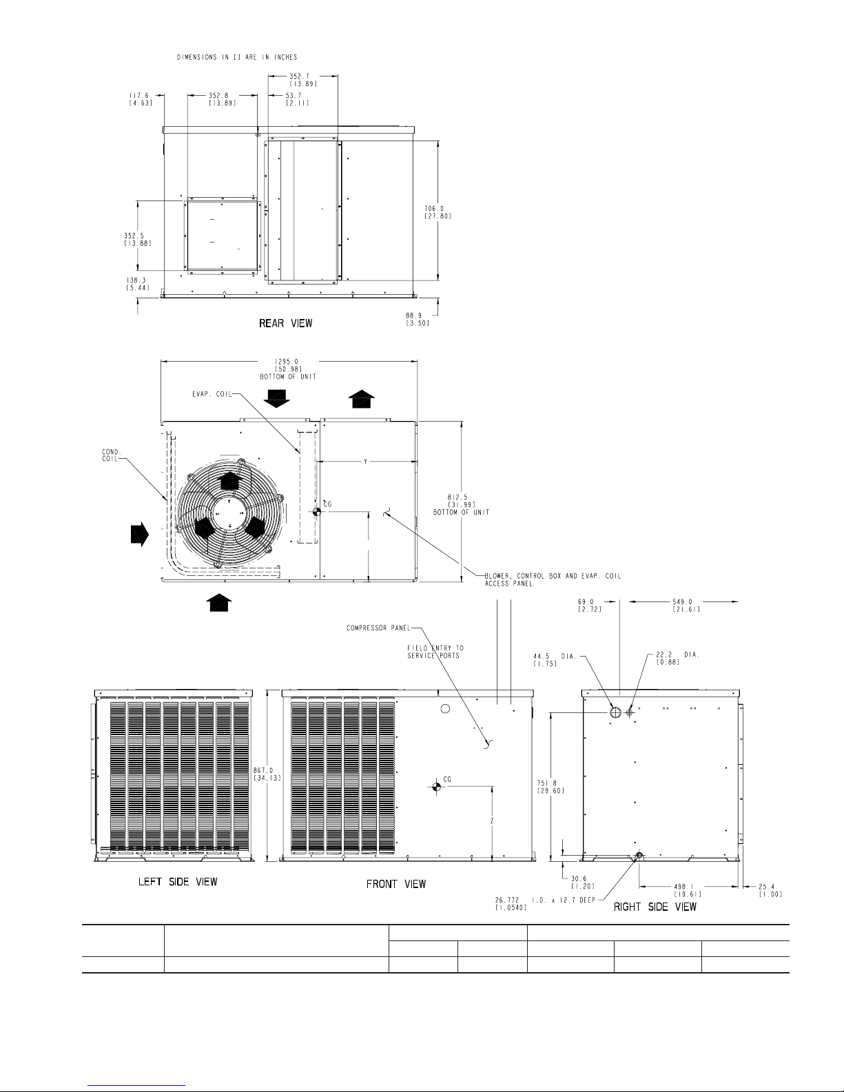
Fig. 4—Unit Base Dimensions, 50ZH060
UNIT ELECTRICAL CHARACTERISTICS
UNIT WEIGHT CENTER OF GRAVITY IN. (MM)
lb kg X Y Z
50ZH060 208/230-1-60, 208/230-3-60, 460-3-60 368 167 14.0 (356) 20.0 (508) 16.0 (406)
C00158
REQUIRED CLEARANCE FOR OPERATION AND SERVICING
INCHES [mm]
CONDENSER . COIL ACCESS SIDE..............................................30.00 [762.0]
POWER ENTRY SIDE....................................................................30.00 [762.0]
(EXCEPT FOR NEC REQUIREMENTS)
UNIT TOP.......................................................................................48.00 [1219.2]
SIDE OPPOSITE DUCTS ..............................................................30.00 [762.0]
LEGEND
NEC – National Electrical Code
NOTES:
1. Clearances must be maintained to prevent recirculation of air from outdoor-
fan discharge, with the exception of the condenser coil (36.00 in [914.0 mm]. A
removable fence or barricade requires no clearance.
2. Dimensions are in inches. Dimensions in [ ] are in millimeters.
REQUIRED CLEARANCE TO COMBUSTIBLE MATL.
INCHES [mm]
TOP OF UNIT.........................................................................................0
DUCT SIDE OF UNIT.............................................................................0
SIDE OPPOSITE DUCTS ......................................................................0
BOTTOM OF UNIT.................................................................................0
NEC. REQUIRED CLEARANCES.
INCHES [mm]
BETWEEN UNITS, POWER ENTRY SIDE....................................42.00 [1066.8]
UNIT AND UNGROUNDED SURFACES, POWER ENTRY SIDE.36.00 [914.0]
UNIT AND BLOCK OR CONCRETE WALLS AND OTHER
GROUNDED SURFACES, POWER ENTRY SIDE.........................42.00 [1066.8]
5
Page 6
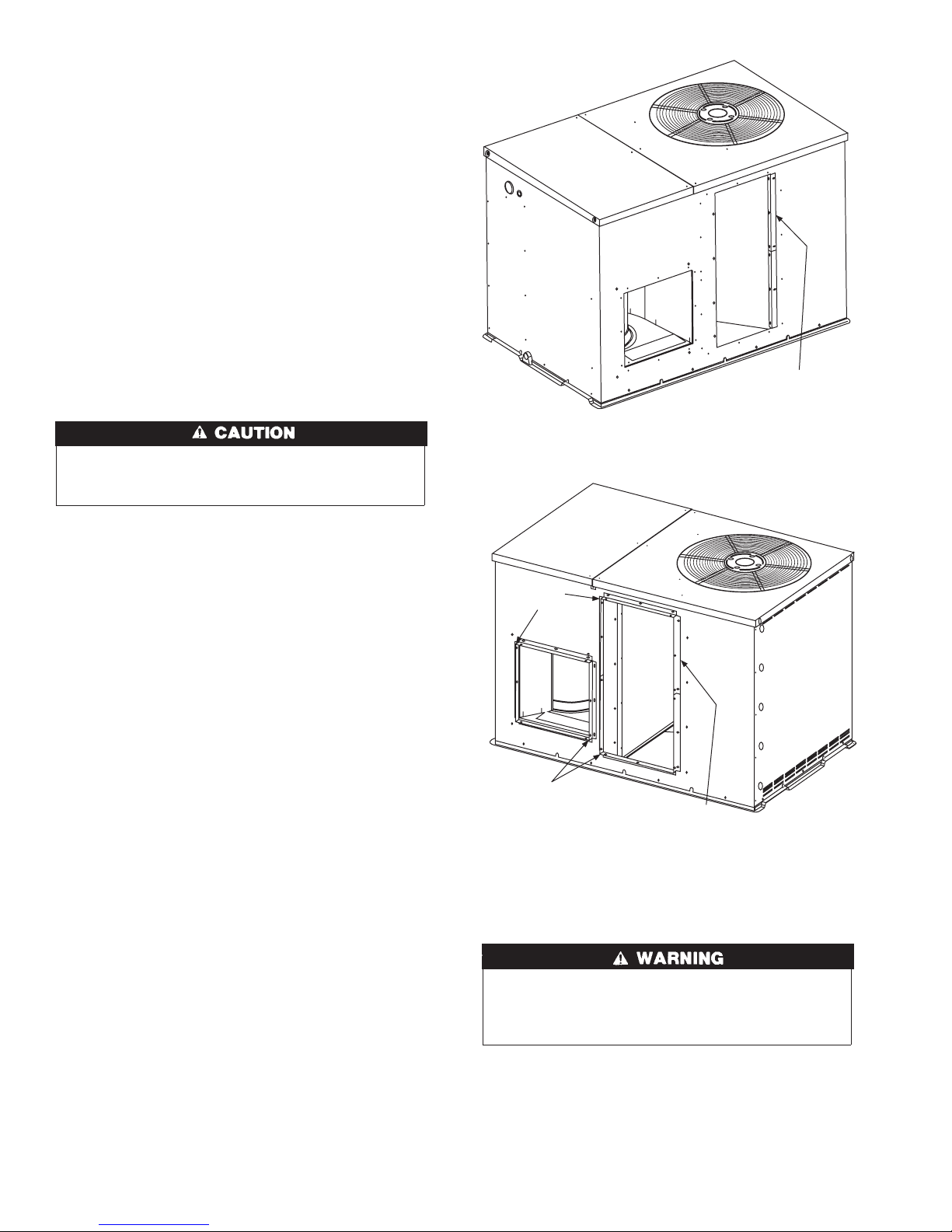
INSTALL FLANGES FOR DUCTWORK CONNECTIONS
(50ZH060 ONLY)
The 50ZH060 units are shipped with flanges which must be
field-installed on the unit.
To install unit flanges:
1. Five pieces of flange are shipped on the return-air opening of
the unit. Remove the flanges from the shipping position (See
Fig. 5). Screws are field-supplied.
2. One piece of flange is used as it is shipped (straight). Bend the
other 4 pieces at right angles.
3. Install the straight flange on the right side of the return-air
opening in holes provided. (See Fig. 6). Flanges should stick
out from unit to allow for connection of ductwork.
4. Install 2 hand-formed flanges onto return air opening in holes
provided to form a rectangle around the return air opening.
5. Install remaining 2 hand-formed flanges around discharge air
opening in holes provided.
6. Ductwork can now be attached to flanges.
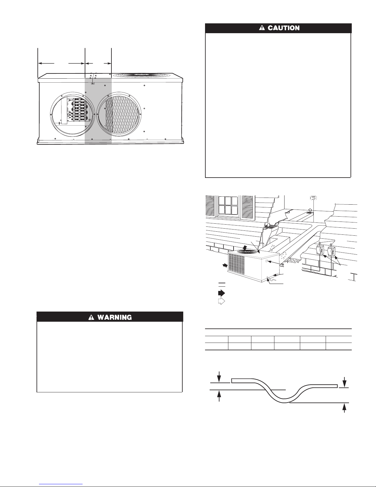
When designing and installing ductwork, consider the following:
When connecting ductwork to units, do not drill deeper than
3/4 inch in shaded area shown in Fig. 7 or coil may be
damaged.
• All units should have field-supplied filters installed in the
return-air side of the unit. Recommended sizes for filters are
shown in Table 1.
• Avoid abrupt duct size increases and reductions. Abrupt change
in duct size adversely affects air performance.
IMPORTANT: Use flexible connectors between ductwork and
unit to prevent transmission of vibration. Use suitable gaskets to
ensure weathertight and airtight seal. When electric heat is
installed, use fire proof canvas (or similar heat resistant material)
connector between ductwork and unit discharge connection. If
flexible duct is used, insert a sheet metal sleeve inside duct. Heat
resistant duct connector (or sheet metal sleeve) must ectend 24–in.
from the unit discharge connection flange into the ductwork.
• Size ductwork for cooling air quantity (cfm). The minimum air
quantity for proper electric heater operation is listed in Table 2.
Heater limit switches may trip at air quantities below those
recommended.
• Insulate and weatherproof all external ductwork. Insulate and
cover with a vapor barrier all ductwork passing through
conditioned spaces. Follow latest Sheet Metal and Air Conditioning Contractors National Association (SMACNA) and Air
Conditioning Contractors Association (ACCA) minimum installation standards for residential heating and air conditioning
systems.
• Secure all ducts to building structure. Flash, weatherproof, and
vibration-isolate duct openings in wall or roof according to
good construction practices.
Figure 8 shows a typical duct system with 50ZH unit installed.
CONVERTING HORIZONTAL DISCHARGE UNITS TO
DOWNFLOW (VERTICAL) DISCHARGE
Before performing service or maintenance operations on
system, turn off main power to unit and install lockout tag.
Turn off accessory heater power switch if applicable. Electrical shock can cause serious injury or death.
Units are dedicated side supply products. They are not convertible
to vertical air supply. A field-supplied plenum must be used to
convert to vertical air discharge.
Step 6—Provide for Condensate Disposal
NOTE: Be sure that condensate-water disposal methods comply
with local codes, restrictions, and practices.
Fig. 5—Shipping Location of Duct Flanges
(Size 060 Only)
C00005
FIVE PIECES OF DUCT
FLANGE ATTACHED
HERE FOR SHIPMENT
Fig. 6—Flanges Installed on 50ZH060 Units
C00006
HAND
FORM
HAND FORM
STRAIGHT PIECE
6
Page 7
Unit removes condensate through a 1 3/64-in. ID hole (using
3/4-in. OD piping or tubing) which is located at the end of the unit.
See Fig. 2-4 for location of condensate connection.
Condensate water can be drained directly onto the roof in rooftop
installations (where permitted) or onto a gravel apron in groundlevel installations. Install a field-supplied condensate trap at end of
condensate connection to ensure proper drainage. Make sure that
the outlet of the trap is at least 1 in. lower than the drain-pan
condensate connection to prevent the pan from overflowing. Prime
the trap with water. When using a gravel apron, make sure it slopes
away from the unit.
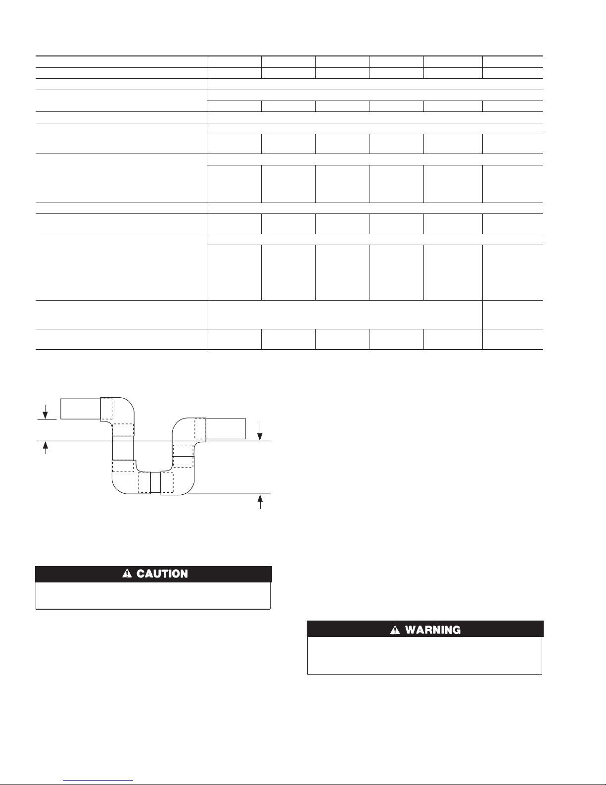
If the installation requires draining the condensate water away
from the unit, install a 2-in. trap using a 3/4-in. OD tubing or pipe.
(See Fig. 9 and 10.) Make sure that the outlet of the trap is at least
1 in. lower than the unit drain-pan condensate connection to
prevent the pan from overflowing. Prime the trap with water.
Connect a drain tube using a minimum of 3/4-in. PVC, 3/4-in.
CPVC, or 3/4-in. copper pipe (all field supplied). Do not undersize
the tube. Pitch the drain tube downward at a slope of at least 1 in.
for every 10 ft of horizontal run. Be sure to check the drain tube
for leaks. Prime trap at the beginning of the cooling season
start-up. Allowable glues for condensate trap connection are:
Standard ABS, CPVC, or PVC cement.
Step 7—Install Electrical Connections
The unit cabinet must have an uninterrupted, unbroken
electrical ground to minimize the possibility of personal
injury if an electrical fault should occur. This ground may
consist of an electrical wire connected to the unit ground in
the control compartment, or conduit approved for electrical
ground when installed in accordance with NEC (National
Electrical Code), ANSI (American National Standards
Institute)/NFPA (latest edition) (in Canada, Canadian Electrical Code CSA C22.1) and local electrical codes. Failure to
adhere to this warning could result in serious injury or death.
Failure to follow these precautions could result in damage to
the unit being installed:
1. Make all electrical connections in accordance with NEC
ANSI/NFPA (latest edition) and local electrical codes
governing such wiring. In Canada, all electrical connections must be in accordance with CSA standard C22.1
Canadian Electrical Code Part 1 and applicable local
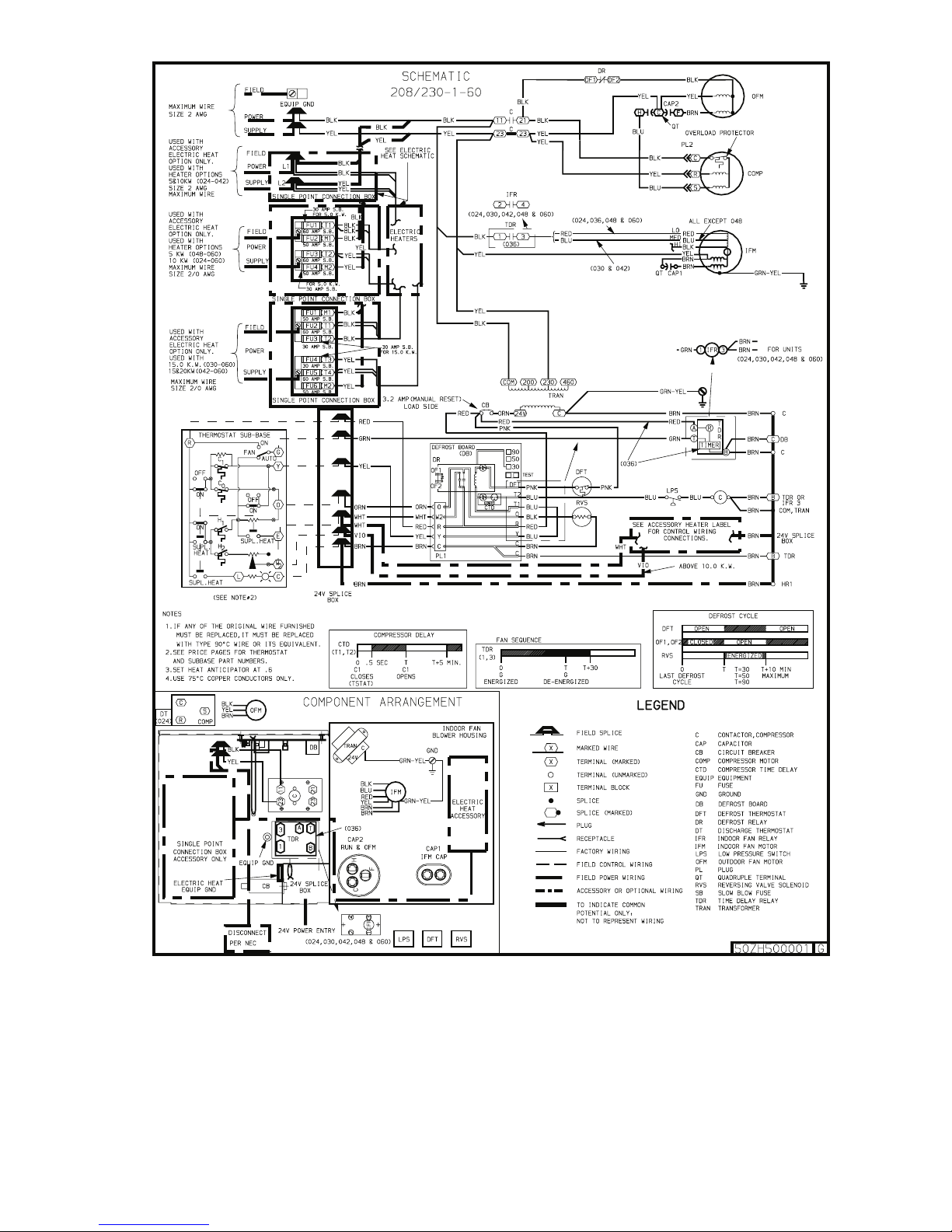
codes. Refer to unit wiring diagram.
2. Use only copper conductor for connections between
field-supplied electrical disconnect switch and unit. DO
NOT USE ALUMINUM WIRE.
3. Be sure that high-voltage power to unit is within operating
voltage range indicated on unit rating plate.
4. Insulate low-voltage wires for highest voltage contained
within conduit when low-voltage control wires are run in
same conduit as high-voltage wires.
5. Do not damage internal components when drilling through
any panel to mount electrical hardware, conduit, etc. On
3-phase units, ensure phases are balanced within 2 percent.
Consult local power company for correction of improper
voltage and/or phase imbalance.
HIGH-VOLTAGE CONNECTIONS
The unit must have a separate electrical service with a fieldsupplied, waterproof disconnect switch mounted at, or within sight
from the unit. Refer to the unit rating plate for maximum
fuse/circuit breaker size and minimum circuit amps (ampacity) for
wire sizing. See Table 3 for electrical data.
Fig. 7—Area Not to Be Drilled More Than 3/4-in.
C00007
19.17″ 3.92″
Fig. 8—Typical installation
Table 2—Minimum Airflow for Safe Electric Heater
Operation (CFM)
SIZE
024 030 036 042 048 060
600 750 900 1050 1200 1500
C00008
C00008
TOP COVER
INDOOR
THERMOSTAT
DISCONNECT
PER NEC*
(UNIT AND
ELECTRIC
HEATER)
FROM
POWER
SOURCE
RETURN
AIR
POWER AND
LOW-VOLTAGE
ENTRY
COMPOSITE
RUST-PROOF
BASEPAN
CONDENSATE
DRAIN
CONNECTION
*Separate disconnect per NEC
(National Electrical Code) required
for electric heater when singlepoint conection is not used.
Power Wiring
Control Wiring
Condenser Airflow
Evaporator Airflow
Fig. 9—Condensate Trap (Using Tubing)
C99013
1” (25mm) MIN.
2” (50mm) MIN.
TRAP
OUTLET
7
Page 8
The field-supplied disconnect may be mounted on the unit over the
high-voltage inlet hole. See Fig. 2-4.
Operation of unit on improper line voltage constitutes abuse
and may cause unit damage that could affect warranty.
ROUTING POWER LEADS INTO UNIT
Use only copper wire between disconnect and unit. The high-
voltage leads should be in a conduit until they enter the unit;
conduit termination at the unit must be watertight. Run the
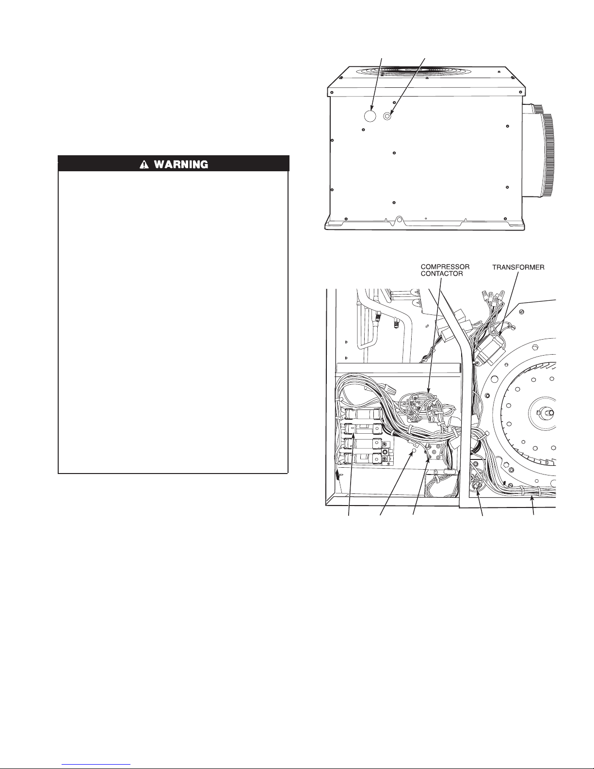
high-voltage leads through the hole on the control box side of the
unit (see Fig. 11 for location). When the leads are inside the unit,
run leads to the control box (Fig. 12). For single-phase units,
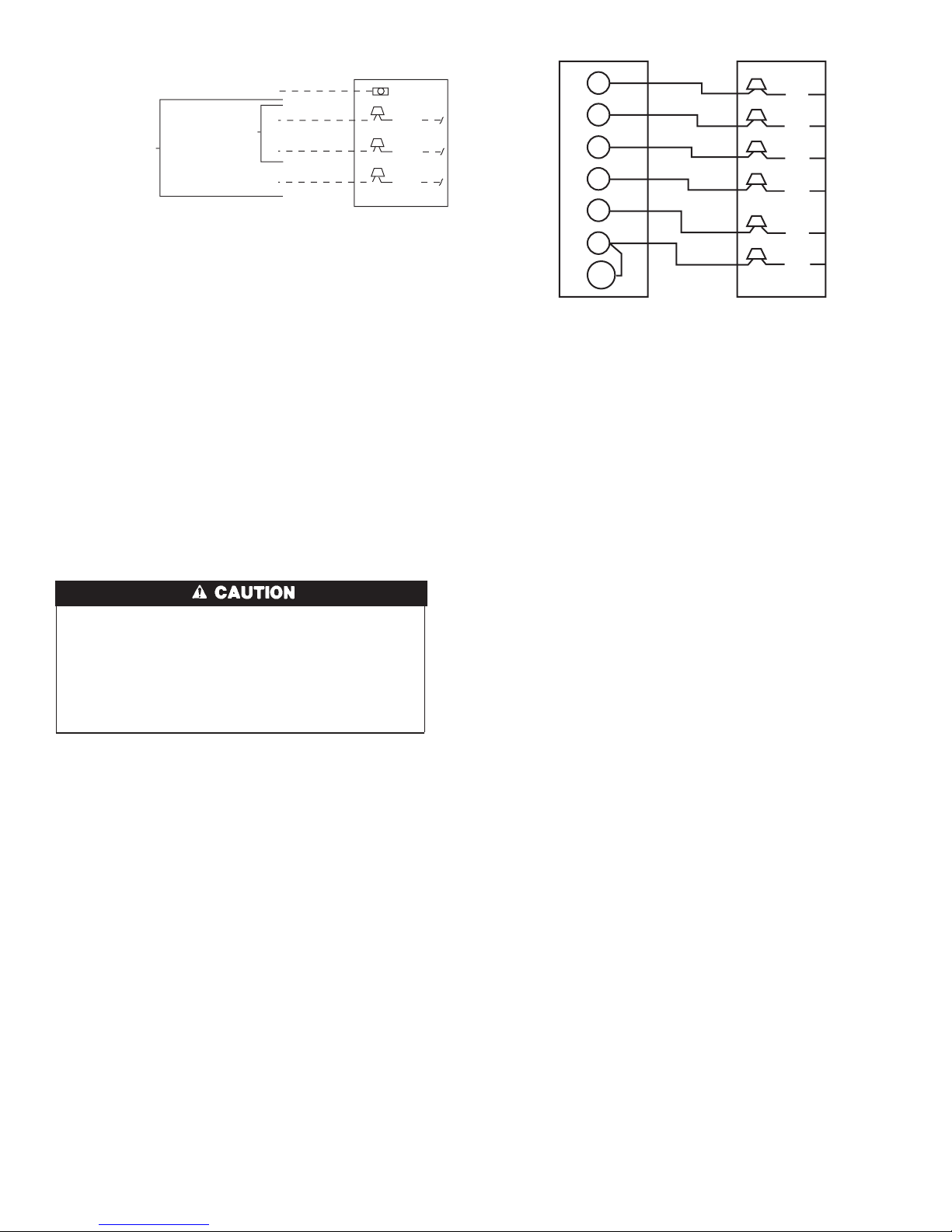
connect leads to the black and yellow wires; for 3-phase units,
connect the leads to the black, yellow, and blue wires (see Fig. 13).
CONNECTING GROUND LEAD TO UNIT GROUND
Refer to Fig. 12 and 13. Connect the ground lead to the chassis
using the unit ground lug in the control box.
ROUTING CONTROL POWER WIRES
Form a drip-loop with the thermostat leads before routing them
into the unit. Route the thermostat leads through grommeted hole
provided in unit into unit control box (See Fig. 11). Connect
thermostat leads and unit power leads as shown in Fig. 13 & 14.
Route thermostat wires through grommet providing a drip-loop at
the panel. Connect low-voltage leads to the thermostat as shown in
Fig. 14.
The unit transformer supplies 24-v power for complete system
including accessory electrical heater. Transformer is factory wired
for 230-v operation. If supply voltage is 208 v, rewire transformer
primary as described in the Special Procedures for 208-v Operation section below.
ACCESSORY ELECTRIC HEAT WIRING
Refer to accessory electric heat installation instructions for infor-
mation on installing accessory electric heat. Accessory electric
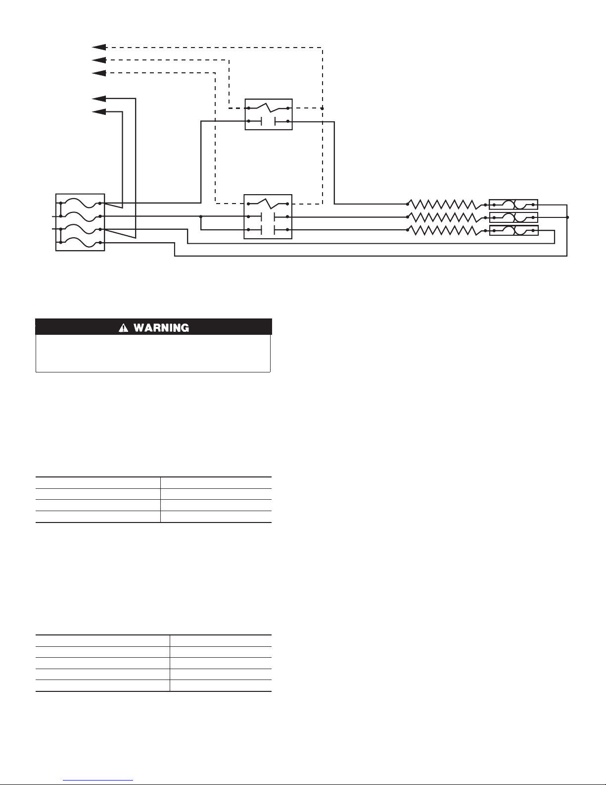
heat wiring is shown in Fig. 15A & 15B.
SPECIAL PROCEDURES FOR 208-V OPERATION
Make sure that the power supply to the unit is switched OFF
and install lockout tag before making any wiring changes.
Electrical shock can cause serious injury or death.
1. Remove wirenut from connection of ORG wire to BLK wire.
Disconnect the ORG transformer-primary lead from the BLK
wire. Save wirenut. See unit wiring label.
2. Remove the wirenut from the terminal on the end of the RED
transformer-primary lead.
3. Save the wirenut.
Table 1 — Physical Data
UNIT 50ZH 024 030 036 042 048 060
OPERATING WEIGHT (lbs) 232 254 277 295 328 368
COMPRESSOR TYPE Scroll
REFRIGERANTCharge(lb)
R-22
3.7 5.85.96.69.19.7
REFRIGERANT METERING DEVICE Acutrol™ System
OUTDOOR COIL
Rows...Fins/in.
Face Area (sq ft)
Copper Tubes, Aluminum Plate Fins
1...17
7.9
2...17
6.7
1...17
11.1
2...17
9.3
2...17
11.1
2...17
12.7
OUTDOOR-FAN MOTOR CFM
Nominal Rpm
Motor Hp
Diameter (in.)
Propeller
1800
825
1/8
20
2000
1100
1/4
20
2600
1100
1/4
20
2600
1100
1/4
20
2600
1100
1/4
20
3200
1100
1/2
20
INDOOR COIL Copper Tubes, Aluminum Plate Fins
Rows...Fins/in.
Face Area (sq ft)
2...15
3.1
3...15
3.1
3...15
4.0
3...15
4.0
4...15
4.4
4...15
4.9
INDOOR FAN MOTOR
Blower Motor Size (in.)
Nominal Cfm
Rpm Range
Number of Speeds
Factory Speed Setting
Motor Hp
Direct Drive
10x8
800
550-1000
3
Low
1/4
10x8
1000
550-1000
3
Med
1/4
10x9
1200
800-1050
3
Low
1/2
10x9
1400
800-1050
3
Med
1/2
10x9
1600
1000-1100
2
Low
3/4
10x10
2000
950-1100
3
Low
1
CONNECTING DUCT SIZES
Supply Air (in.)
Return Air (in.)
Round
14
14
Square
13.9 x 13.9
13.9 x 27.8
FIELD-SUPPLIED RETURN-AIR FILTER†
Throwaway (in.)
24x24 24x24 24x24 24x24 24x30 24x30
* 460-v motors are 2-speed or 3-speed.
†Required filter sizes shown are based on the ARI (Air Conditioning and Refrigeration Institute) rated airflow at a velocity of 300 ft/min for throwaway type or 450 ft/min
for high capacity type. Recommended filters are 1-in. thick.
Fig. 10–PVC Condensate Trap
C00009
TRAP
OUTLET
2" min.
1" min.
8
Page 9
4. Connect the RED lead to the BLK wire from which the ORG
lead was disconnected. Insulate with wirenut from Step 1.
5. Using the wirenut removed from the RED lead, insulate the
loose terminal on the ORG lead.
6. Wrap the wirenuts with electrical tape so that the metal
terminals cannot be seen.
Indoor blower-motor speeds may need to be changed for 208-v
operation. Refer to Indoor Airflow and Airflow Adjustments
section. (See Table of Contents for page number.)
PRE-START-UP
Failure to observe the following warnings could result in
serious injury or death:
1. Follow recognized safety practices and wear protective
goggles when checking or servicing refrigerant system.
2. Do not operate compressor or provide any electric power to
unit unless compressor terminal cover is in place and
secured.
3. Do not remove compressor terminal cover until all electrical sources are disconnected and lockout tag is installed.
4. Relieve all pressure from both high- and low-pressure sides
of the system before touching or disturbing anything inside
terminal box if refrigerant leak is suspected around compressor terminals. Use accepted methods to recover refrigerant.
5. Never attempt to repair soldered connection while refrigerant system is under pressure.
6. Do not use torch to remove any component. System
contains oil and refrigerant under pressure. To remove a
component, wear protective goggles and proceed as follows:
a. Shut off electrical power to unit and install lockout tag.
b. Relieve all refrigerant from system using both high- and
low-pressure ports. Use accepted methods to recover
refrigerant.
c. Cut component connecting tubing with tubing cutter and
remove component from unit.
d. Carefully unsweat remaining tubing stubs when neces-
sary. Oil can ignite when exposed to torch flame.
Use the Start-Up Checklist supplied at the end of this book and
proceed as follows to inspect and prepare the unit for initial
start-up:
1. Remove all access panels.
2. Read and follow instructions on all DANGER, WARNING,
CAUTION, and INFORMATION labels attached to, or
shipped with, unit.
Make the following inspections:
a. Inspect for shipping and handling damages such as broken
lines, loose parts, disconnected wires, etc.
b. Inspect for oil at all refrigerant tubing connections and on
unit base. Detecting oil generally indicates a refrigerant
leak. Leak-test all refrigerant tubing connections using
electronic leak detector, or liquid-soap solution. If a refrigerant leak is detected, see following Check for Refrigerant
Leaks section.
c. Inspect all field- and factory-wiring connections. Be sure
that connections are completed and tight. Ensure wires do
not contact refrigerant tubing or sheet metal edges.
d. Inspect coil fins. If damaged during shipping and handling,
carefully straighten fins with a fin comb.
3. Verify the following conditions:
a. Make sure that outdoor-fan blade is correctly positioned in
fan orifice. Top edge of blade should be 3.125 in. down
from outdoor coil outlet grille (size 024–048, See Fig. 21)
or hub should be 0.708-in. away from motor end bell (size
060, See Fig. 22). See Outdoor Fan Adjustment section.
b. Make sure that air filter is in place.
c. Make sure that condensate drain trap is filled with water to
ensure proper drainage.
d. Make sure that all tools and miscellaneous loose parts have
been removed.
START-UP
Use the Start-Up Checklist supplied at the end of this book and
proceed as follows:
Fig. 11—Unit Electrical Connection
C00010
HIGH-VOLTAGE
POWER WIRING
ENTRY HOLE
LOW-VOLTAGE
WIRING ENTRY
HOLE
Fig. 12—Control Box Wiring
C00011
ELECTRIC
HEATER
FUSES
GROUND
LUG
INDOOR
FAN
RELAY
OUTDOOR FAN MOTOR
AND COMPRESSOR
START CAPACITOR
HIGH
VOLTAGE
LEADS
9
Page 10
Step 1—Check for Refrigerant Leaks
LOCATE AND REPAIR REFRIGERANT LEAKS AND
CHARGE THE UNIT AS FOLLOWS:
1. Using both high- and low-pressure ports, locate leaks and
reclaim remaining refrigerant to relieve system pressure.
2. Repair leak following accepted practices.
NOTE: Install a liquid-line filter drier whenever the system has
been opened for repair.
Step 2—Start-Up Cooling Section and Make Adjustments
Complete the required procedures given in the Pre-Start- Up
section this page before starting the unit. Do not jumper any
safety devices when operating the unit.
Do not operate the compressor when the outdoor temperature
is below 40 F.
Do not rapid-cycle the compressor. Allow 5 minutes between
‘‘on’’ cycles to prevent compressor damage.
CHECKING COOLING CONTROL OPERATION
Start and check the unit for proper cooling control operation as
follows:
1. Place room thermostat SYSTEM switch in OFF position.
Observe that blower motor starts when FAN switch is placed
in ON position and shuts down within 30 seeconds when FAN
switch is placed in AUTO position.
2. Place SYSTEM switch in COOL position and FAN switch in
AUTO position. Set cooling control below room temperature.
Observe that compressor, outdoor fan, and indoor blower
motors start and that reversing valve shifts. Observe that
cooling cycle shuts down when control setting is satisfied.
Reversing valve (RV) remains energized.
3. Place system switch in HEAT position. Observe that compressor, indoor fan and outdoor fan energize (Reversing Valve is
deenergized in heat pump heating mode). Set control above
room temperature. Observe that heating cycle shuts down
when control setting is satisfied.
4. When using an automatic changeover room thermostat, place
both SYSTEM and FAN switches in AUTO. positions.
Observe that unit operates in Cooling mode when temperature
control is set to ‘‘call for cooling’’ (below room temperature),
and unit operates in Heating mode when temperature control
is set to “call for heating” (above room temperature).
COMPRESSOR ROTATION
On 3–Phase units it is important to be certain compressor is
rotating in the proper direction. To determine whether or not
compressor is rotating in the proper direction:
1. Connect service gages to suction and discharge pressure
fittings.
2. Energize the compressor.
3. The suction pressure should drop and the discharge pressure
should rise, as is normal on any start-up.
If the suction pressure does not drop and the discharge pressure
does not rise to normal levels:
1. Turn off power to the unit and tag disconnect.
2. Reverse any two of the unit power leads.
3. Turn on power to the unit.
The suction and discharge pressure levels should now move to
their normal start-up levels.
NOTE: When the compressor is rotation in the wrong direction,
the unit makes an elevated level of noise and does not provide
cooling.
Step 3—Refrigerant Charge
Refrigerant Charge — Amount of refrigerant charge is listed on
unit nameplate and in Table 1. Refer to Carrier Refrigerant Service
Techniques Manual, Refrigerants section. Unit panels must be in
place when unit is operating during charging procedure. Unit must
operate a minimum of 15 minutes before checking charge.
NO CHARGE
Refer to Carrier Refrigerant Service Techniques. Use standard
evacuating techniques. After evacuating system, weigh in the
specified amount of refrigerant (refer to Table 1).
LOW CHARGE COOLING
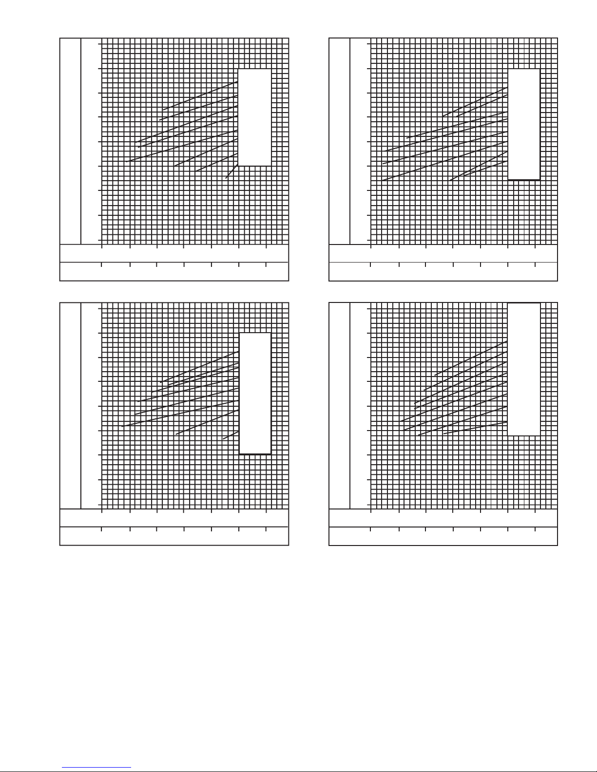
Using cooling charging chart (see Fig. 16–21),Vary refrigerant
until conditions of the chart are met. Note that charging chart is
different from those normally used. Charts are based on charging
the units to the correct superheat for the various operating
conditions. An accurate pressure gage and temperature-sensing
device is required. Connect the pressure gauge to the service port
on the suction line. Connect temperature sensing device to the
suction line near the compressor and insulate it so that outdoor
ambient temperature does not affect reading.
TO USE THE COOLING CHARGING CHART
This method is to be used in cooling mode only. Take the outdoor
ambient temperature and read the suction pressure gauge. Refer to
3-PHASE
CONNECTIONS
TO DISCONNECT
PER NEC
SINGLE-PHASE
CONNECTIONS
TO DISCONNECT
PER NEC
GROUND
LEAD
UNIT GROUND
BLK
YEL
BLU
L
L
L
C00012
Fig. 13—Line Power Connections
Y
C
W2
E
G
R
O
THERMOSTAT
AND SUBBASE
UNIT CONTROL POWER
SPLICE BOX
BRN
WHT
YEL
GRN
RED
ORN
C99056
Fig. 14—Control Connections
10
Page 11
charts to determine what the suction temperature should be. If
suction temperature is high, add refrigerant. If suction temperature
is low, carefully recover some of the charge. Recheck the suction
pressure as charge is adjusted.
Example: (See Fig. 16)
Outdoor Temperature —85°F
Suction Pressure—74 psig
Suction Temperature should be—60°F
Note—Suction Temperature may vary +/- 5°F.
HEATING MODE CHARGE
Do not attempt to adjust charge by cooling methods while in heat
pump heating mode. Recover refrigerant and weigh in according to
unit data plate refrigerant data.
Step 4—Indoor Airflow and Airflow Adjustments
NOTE: For cooling operation, the recommended airflow is 350 to
450 cfm per each 12,000 Btuh of rated cooling capacity.
Table 4 shows dry coil air delivery for horizontal discharge units.
Tables 5-7 show pressure drops.
Fig. 15A—Typical Unit Electrical Diagram (208/230–1–60)
C01022
11
Page 12
NOTE: Be sure that all supply- and return-air grilles are open,
free from obstructions, and adjusted properly.
Disconnect electrical power to the unit and install lockout tag
before changing blower speed. Electrical shock can cause
serious injury or death.
Airflow can be changed by changing the lead connections of the
blower motor.
Units 50ZH024, 036, 048, and 060 blower motors are factory
wired for low speed operation. Units 50ZH030 and 042 are factory
wired for medium speed operation.
FOR 208/230-V
The motor leads are color-coded as follows:
To change the speed of the indoor fan motor (IFM), remove the fan
motor speed leg lead from the indoor fan relay (IFR) with units
024, 030, 042, 048 & 060 or the time delay relay (TDR) on 036
size and replace with lead for desired blower motor speed. Insulate
the removed lead to avoid contact with chassis parts.
FOR 460-V MOTORS
The motor leads are color coded as follows:
To change the speed of the indoor fan motor (IFM) from low speed
to high speed, remove the red lead from the indoor-fan relay (IFR).
ON 2–Speed Motors: Insulate the red lead to avoid contact with
any chassis parts. Separate the black lead from the purple lead.
Connect the black lead to the IFR. Insulate the purple lead to avoid
contact with any chassis parts. ON 3–Speed Motors: remove the
fan motor speed leg lead from the indoor (indoor) fan relay (IFR)
and replace with lead for desired blower motor speed.
Step 5—Unit Controls
All compressors have the following internal-protection controls.
HIGH-PRESSURE RELIEF VALVE
This valve opens when the pressure differential between the low
and high side becomes excessive (024 size has temperature relief
only).
LOSS OF CHARGE SWITCH
Located on the outdoor liquid line is a low-pressure switch which
functions as a loss-of-charge switch. This switch contains a
Schrader core depressor. This switch opens at 7 psig and closes at
22 psig. No adjustment is necessary.
COMPRESSOR OVERLOAD
This overload interrupts power to the compressor when either the
current or internal temperature become excessive, and automatically resets when the internal temperature drops to a safe level.
This overload may require up to 60 minutes (or longer) to reset;
therefore, if the internal overload is suspected of being open,
disconnect the electrical power to the unit and check the circuit
through the overload with an ohmmeter or continuity tester.
Step 6—Sequence of Operation
FAN OPERATION
The FAN switch on the thermostat controls indoor fan operation.
When the FAN switch is placed in the ON position, the IFR
(indoor-fan relay) is energized through the G terminal on the
thermostat. The normally-open contacts close, which then provide
power to the indoor (evaporator) fan motor (IFM). The IFM will
run continuously when the FAN switch is set to ON.
When the FAN switch is set to AUTO, the thermostat deenergizes
the IFR (provided there is not a call for cooling). The contacts open
and the IFM is deenergized. The IFM will be energized only when
there is a call for cooling, in heat pump heating mode or if the unit
is equipped with accessory electric heat, the indoor-fan motor will
also run while the accessory electric heat is energized.
Fig. 15B—Accessory Electric Heater Wiring
C00014
C
W1
W1
TO
UNIT POWER
WIRING
BLK
YEL
BRN (COMMON)
VIO (STEP 2)
WHT ( STEP 1)
CONTACTOR 2
YEL
BRN
YEL
CONTACTOR 1
YEL
YEL
BRN
YEL
YEL
FUSE BLOCK
L2
L1
YEL
YEL
BLK
BLK
F3
F4
F1
F2
EL 1
EL 2
EL 3
BLK
BLK
BLK
AUTO-LIMIT
3-SPEED 2-SPEED
black = high speed black = high speed
blue = medium speed -
red = low speed red = low speed
3-SPEED (060 ONLY) 2-SPEED
black = high speed black = to purple
- yellow = line
orange = medium speed purple = to black
blue = low speed red = line
12
Page 13
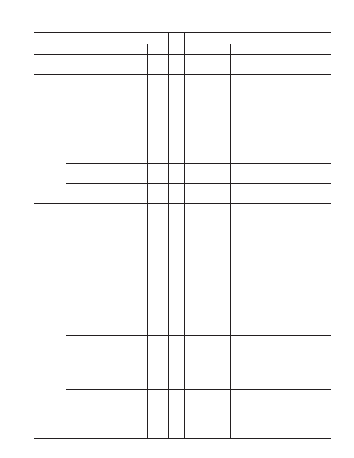
Table 3—Electrical Data—50ZH
UNIT 50ZH
SIZE
(–SERIES, IF
USED)
V-PH-HZ
VOLTAGE
RANGE
COMPRESSOR
OFM
FLA
IFM
FLA
ELECTRIC HEAT SINGLE POINT POWER SUPPLY
MIN MAX RLA LRA Nominal KW* FLA MCA
FUSE OR
CKT BKR
MOCP
024–311 208/230–1–60 187 254 11.4 56.0 0.9 2.4
-/-
3.8/5.0
5.6/7.5
7.5/10.0
-/-
18.3/20.8
26.9/31.3
36.1/41.7
17.6/17.6
40.4/43.6
51.2/56.7
62.7/69.7
25/25
45/45
60/60
-
-
-
-
70/70
024–321 208/230–1–60 187 254 12.1 54.0 0.9 2.4
-/-
3.8/5.0
5.6/7.5
7.5/10.0
-/-
18.3/20.8
26.9/31.3
36.1/41.7
18.4/18.4
41.3/44.4
52.1/57.6
63.6/70.6
25/25
45/45
60/60
—
—
—
—
70/80
030
208/230–1–60 187 254 14.4 73.0 1.5 2.4
-/-
3.8/5.0
5.6/7.5
7.5/10.0
11.3/15.0
-/-
18.3/20.8
26.9/31.3
36.1/41.7
54.2/62.5
21.9/21.9
44.8/47.9
55.5/61.0
67.0/74.0
89.8/100.0
30/30
45/50
60/–
—
–
—
—
–/70
70/80
90/110
208/230–3–6 187 254 10.0 63.0 1.5 5.8
-/-
3.8/5.0
7.5/10.0
11.3/15.0
-/-
10.4/12.0
20.8/24.1
31.3/36.1
16.8
29.9/31.8
42.8/46.9
56.1/61.9
20
35/35
45/50
60/–
—
—
—
–/70
036
208/230–1–60 187 254 17.7 93.0 1.5 2.8
-/-
3.8/5.0
5.6/7.5
7.5/10.0
11.3/15.0
-/-
18.1/20.8
26.9/31.3
36.1/41.7
54.2/62.5
26.4/26.4
49.3/52.4
60.1/65.6
74.6/78.6
94.3/104.6
35/35
50/60
—
—
—
—
—
70/70
80/80
100/110
208/230–3–60 187 254 11.4 77.0 1.5 2.8
-/-
3.8/5.0
7.5/10.0
11.3/15.0
-/-
10.4/12.0
20.8/24.1
31.3/36.1
18.6/18.6
31.7/33.6
44.6/48.7
57.8/63.7
25/25
35/35
45/50
60/-
—
—
—
–/70
460–3–60 414 508 5.7 39.0 0.8 2.0
—
5
10
15
—
6.0
12.0
18.0
9.9
17.4
24.9
32.4
15
20
25
35
—
—
—
—
042
208/230–1–60 187 254 22.0 103.0 1.5 2.8
-/-
3.8/5.0
5.6/7.5
7.5/10.0
11.3/15.0
15/20
-/-
18.3/20.8
26.9/31.3
36.1/41.7
54.3/62.5
72.1/83.3
31.8/31.8
54.7/57.8
65.4/70.9
76.9/83.9
99.7/109.9
121.9/135.9
40/40
60/60
—
—
—
—
—
—
70/80
80/90
100/110
125/150
208/230–3–60 187 254 13.9 88.0 1.5 2.8
-/-
3.8/5.0
7.5/10.0
11.3/15.0
15/20
-/-
10.5/12.0
20.8/24.1
31.4/36.1
41.4/47.9
21.7/21.7
34.8/36.7
47.7/51.8
60.9/66.8
73.4/81.6
30/30
35/40
50/50
—
—
—
—
—
70/70
80/90
460–3–60 414 508 6.8 44.0 0.8 2.0
—
5
10
15
20
—
6.0
12.0
18.0
24.1
11.3
18.8
26.3
33.8
41.4
15
20
30
35
45
—
—
—
—
—
048
208/230–1–60 187 254 21.8 124.0 1.5 4.2
-/-
3.8/5.0
5.6/7.5
7.5/10.0
11.3/15.0
15/20
-/-
18.3/20.8
26.9/31.3
36.1/41.7
54.2/62.5
72.2/83.3
33.0/33.0
55.8/59.0
66.6/72.1
78.1/85.1
100.8/111.1
123.1/137.1
40/40
60/60
—
—
—
—
—
—
70/80
80/90
110/125
125/150
208/230–3–60 187 254 12.8 93.0 1.5 4.2
-/-
3.8/5.0
7.5/10.0
11.3/15.0
15/20
-/-
10.5/12.0
20.8/24.1
31.4/36.1
41.4/47.9
21.7/21.70
34.8/36.7
47.7/51.8
61.0/66.8
73.5/81.6
25/25
35/40
50/60
—
—
—
—
—
70/70
80/90
460–3–60 414 508 6.4 46.5 0.8 4.2
—
5
10
15
20
—
6.0
12.0
18.0
24.1
10.9
18.4
25.9
33.4
40.8
15
20
30
35
45
—
—
—
—
—
060
230–1–60 187 254 27.7 170.0 3.1 6.2
—
3.8/5
5.6/7.5
7.5/10
11.3/15
15.0/20
—
18.3/20.8
26.9/31.3
36.1/41.7
54.3/62.5
72.1/83.3
43.9/43.9
66.8/69.9
77.6/83.1
89.1/96.1
111.8/122.1
134.1/148.1
60/60
—
—
—
—
—
—
70/70
80/90
90/100
125/125
150/150
208/230–3–60 187 254 15.9 124.0 3.1 6.2
-/-
3.8/5.0
7.5/10.0
11.3/15.0
14.9/19.9
-/-
10.5/12.0
20.8/24.1
31.4/36.1
41.4/47.9
29.2/29.2
42.3/44.2
55.2/59.3
68.4/74.3
80.9/89.1
35/35
45/45
60/60
—
—
—
—
—
70/80
90/90
460–3–60 414 508 8.0 59.6 1.5 3.2
—
5
10
15
19.9
—
6.0
12.0
18 .0
23.9
14.7
22.2
29.7
37.2
44.6
20
25
30
40
45
—
—
—
—
—
(See legend following Electrical Data charts)
13
→
Page 14
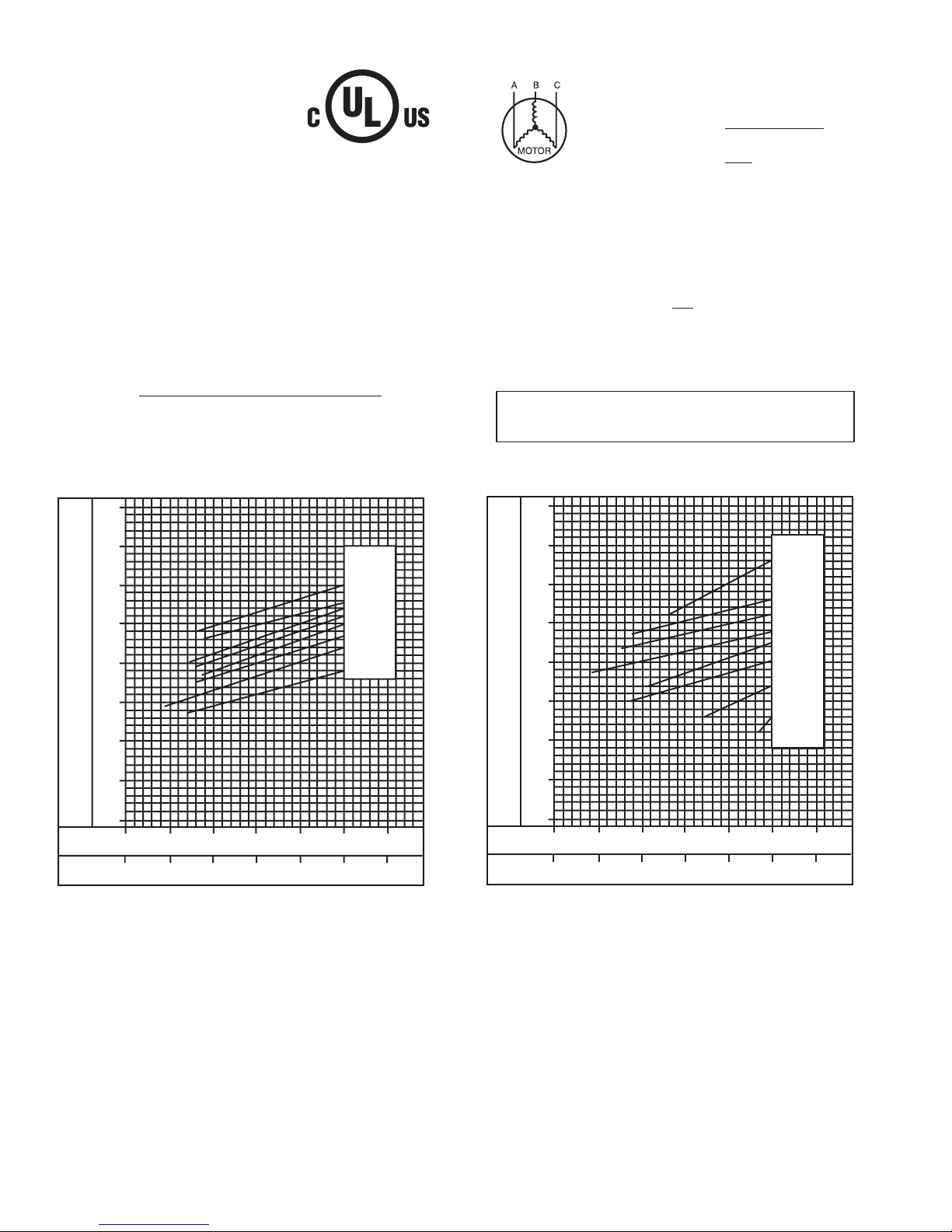
NOTE: Some units are equipped with a time-delay relay. On
these units, the indoor fan remains on for 30 seconds after G or Y
is deenergized.
COOLING
With the thermostat subbase in the cooling position, the thermostat
makes circuit R-O. This energizes the reversing valve solenoid
(RVS) and places the unit in standby condition for cooling.
NOTE: The defrost control board has a 5 minute compressor
anti-short cycle time delay built in between compressor starts.
On a call for cooling, the compressor contactor (C) and the IFR are
energized through the Y and G terminals of the thermostat.
Energizing the compressor contactor supplies power to the compressor and the outdoor (condenser) fan motor (OFM). Energizing
the IFR provides power to the IFM.
When the need for cooling has been satisfied, the OFM, compressor, and IFM (FAN on AUTO) are deenergized. If the unit is
equipped with a 30-second delay (036 size only), the indoor fan
will remain energized for 30 seconds after the compressor is
deenergized. The reversing valve solenoid remains energized.
HEAT PUMP HEATING
On a call for heat, thermostat makes circuits R-Y and R-G. When
compressor time delay (5-minute ± 2 minutes) is completed, a
circuit is made to C, starting COMP and OFM. Circuit R-G also
energizes IFR and starts IFM after 1-second delay.
Should room temperature continue to fall, circuit R-W is made
through second-stage thermostat bulb. If optional electric heat
package is used, a relay is energized, bringing on first bank of
C99024
452=5v
457=7v
455=2v
LEGEND
FLA — Full Load Amps
LRA — Locked Rotor Amps
MCA — Minimum Circuit Amps
MOCP — Maximum Overcurrent Protection
RLA — Rated Load Amps
NOTES:
1. In compliance with NEC (National Electrical Code) requirements
for multimotor and combination load equipment (refer to NEC
Articles 430 and 440), the overcurrent protective device for the
unit shall be Power Supply fuse. Canadian units may be
fuse or circuit breaker.
2. Minimum wire size is based on 60 C copper wire. If other than
60 C wire is used, or if length exceeds wire length in table,
determine size from NEC.
3. Unbalanced 3-Phase Supply Voltage
Never operate a motor where a phase imbalance in supply voltage is greater than 2%.
Use the following formula to determine
the percentage of voltage imbalance.
% Voltage imbalance
max voltage deviation from average voltage
= 100 x
average voltage
EXAMPLE: Supply voltage is 460-3-60.
AB = 452 v
BC = 464 v
AC = 455 v
452 + 464 + 455
Average Voltage =
3
1371
=
3
= 457
Determine maximum deviation from average voltage.
(AB) 457
(BC) 464
(AC) 457
Maximum deviation is 7 v.
Determine percent of voltage imbalance.
7
% Voltage Imbalance = 100 x
457
= 1.53%
This amount of phase imbalance is satisfactory as it is below the
maximum allowable 2%.
IMPORTANT: If the supply voltage phase imbalance is
more than 2%, contact your local electric utility company
immediately.
®
CKT BKR
—
Circuit Breaker
758 110
683 100
621 90
552 80
483 70
414 60
345 50
276 40
207 30
30 40 50 60 70 80 90
-1 41016212732
SUCTION LINE TEMPERATURE (
O
F)
SUCTION LINE TEMPERATURE (OC)
OUTDOOR TEMP
OFO
C
115 46
105 41
95 35
85 29
75 24
65 18
55 13
45 7
SUCTION LINE PRESSURE (KILOPASCALS)
SUCTION LINE PRESSURE (PSIG)
C00162
Fig. 16—Cooling Charging Chart, 50ZH024 Units
758 110
683 100
621 90
552 80
483 70
414 60
345 50
276 40
207 30
30 40 50 60 70 80 90
-1 41016212732
SUCTION LINE TEMPERATURE (
O
F)
SUCTION LINE TEMPERATURE (OC)
SUCTION LINE PRESSURE (KILOPASCALS)
SUCTION LINE PRESSURE (PSIG)
OUTDOOR TEMP
OFO
C
115 46
105 41
95 35
85 29
75 24
65 18
55 13
45 7
C00163
Fig. 17—Cooling Charging Chart, 50ZH030
14
Page 15
supplemental electric heat. When thermostat is satisfied, contacts
open, deenergizing contactor and relay; motors and heaters deenergize. The IFM may be controlled by a time-delay relay that keeps
the fan on for 30 seconds.
DEFROST
Defrost board (DB) is a time and temperature control, which
includes a field-selectable time period between checks for defrost
(30, 50 and 90 minutes). The time period is factory-set at 30
minutes and should only be adjusted by a trained service person.
Electronic timer and defrost cycle start only when contactor is
energized and defrost thermostat (DFT) is closed.
Defrost mode is identical to Cooling mode. The outdoor fan motor
stops because of “OF1” and “OF2” contacts opening on the defrost
board, a bank of optional electric heat turns on to warm air
supplying the conditioned space.
ELECTRIC RESISTANCE HEATING
If accessory electric heaters are installed, on a call for “Emergency
Heat” the thermostat energizes W which energises the heater relay
and in turn energizes the electric heaters. The IFR is energized
which starts the indoor-fan motor. If the heaters are staged, W2 is
energized when the second stage of heating is required. When the
need for heating is satisfied, the heater and IFM are deenergized.
MAINTENANCE
To ensure continuing high performance, and to reduce the possibility of premature equipment failure, periodic maintenance must
be performed on this equipment. This cooling unit should be
inspected at least once each year by a qualified service person. To
troubleshoot cooling of units, refer to Troubleshooting chart in
back of book.
758 110
683 100
621 90
552 80
483 70
414 60
345 50
276 40
207 30
30 40 50 60 70 80 90
-1 41016212732
SUCTION LINE TEMPERATURE (
O
F)
SUCTION LINE TEMPERATURE (
O
C)
SUCTION LINE PRESSURE (KILOPASCALS)
SUCTION LINE PRESSURE (PSIG)
OUTDOOR TEMP
OFO
C
115 46
105 41
95 35
85 29
75 24
65 18
55 13
45 7
C00164
Fig. 18—Cooling Charging Chart, 50ZH036 Units
Fig. 19—Cooling Charging Chart, 50ZH042 Units
C00165
758 110
683 100
621 90
552 80
483 70
414 60
345 50
276 40
207 30
30 40 50 60 70 80 90
-1 41016212732
SUCTION LINE TEMPERATURE (
O
F)
SUCTION LINE TEMPERATURE (OC)
SUCTION LINE PRESSURE (KILOPASCALS)
SUCTION LINE PRESSURE (PSIG)
OUTDOOR TEMP
OFO
C
115 46
105 41
95 35
85 29
75 24
65 18
55 13
45 7
758 110
683 100
621 90
552 80
483 70
414 60
345 50
276 40
207 30
30 40 50 60 70 80 90
-1 41016212732
SUCTION LINE TEMPERATURE (
O
F)
SUCTION LINE TEMPERATURE (
O
C)
SUCTION LINE PRESSURE (KILOPASCALS)
SUCTION LINE PRESSURE (PSIG)
OUTDOOR TEMP
OFO
C
115 46
105 41
95 35
85 29
75 24
65 18
55 13
45 7
C00166
Fig. 20—Cooling Charging Chart, 50ZH048 Units
758 110
683 100
621 90
552 80
483 70
414 60
345 50
276 40
207 30
30 40 50 60 70 80 90
-1 41016212732
SUCTION LINE TEMPERATURE (
O
F)
SUCTION LINE TEMPERATURE (OC)
SUCTION LINE PRESSURE (KILOPASCALS)
SUCTION LINE PRESSURE (PSIG)
OUTDOOR TEMP
OFO
C
115 46
105 41
95 35
85 29
75 24
65 18
55 13
45 7
C00167
Fig. 21—Cooling Charging Chart, 50ZH060 Units
15
Page 16
NOTE TO EQUIPMENT OWNER: Consult your local dealer
about the availability of a maintenance contract.
The ability to properly perform maintenance on this equipment requires certain expertise, mechanical skills, tools and
equipment. If you do not possess these, do not attempt to
perform any maintenance on this equipment, other than those
procedures recommended in the User’s Manual. FAILURE
TO HEED THIS WARNING COULD RESULT IN SERIOUS INJURY, DEATH OR DAMAGE TO THIS EQUIPMENT.
The minimum maintenance requirements for this equipment are as
follows:
1. Inspect air filter(s) each month. Clean or replace when
necessary.
2. Inspect indoor coil, outdoor coil, drain pan, and condensate
drain each cooling and heating season for cleanliness. Clean
when necessary.
3. Inspect blower motor and wheel for cleanliness each cooling
and heating season. Clean when necessary. For first heating
season, inspect blower wheel bimonthly to determine proper
cleaning frequency.
4. Check electrical connections for tightness and controls for
proper operation each cooling season. Service when necessary.
5. Check the drain channel in the top cover periodically for
blockage (leaves, insects). Clean as needed.
Failure to follow these warnings could result in serious injury
or death:
1. Turn off electrical power to the unit and install lockout tag
before performing any maintenance or service on the unit.
2. Use extreme caution when removing panels and parts. As
with any mechanical equipment, personal injury can result
from sharp edges, etc.
3. Never place anything combustible either on, or in contact
with, the unit.
Step 1—Air Filter
NOTE: Never operate the unit without a suitable air filter in the
return-air duct system. Always replace the filter with the same size
as originally installed. See Table 1 for recommended filter sizes
Inspect air filter(s) at least once each month and replace
(throwaway-type) or clean (cleanable-type) at least twice during
each cooling season or whenever the filters become clogged with
dust and lint.
Replace filters with the same dimensional size and type as
originally provided, when necessary.
Step 2—Unit Top Removal (Outdoor-Coil Side)
NOTE: When performing maintenance or service procedures that
require removal of the unit top, be sure to perform all of the routine
maintenance procedures that require top removal, including coil
inspection and cleaning, and condensate drain pan inspection and
cleaning.
Disconnect and tag electrical power to the unit before
removing top. Failure to adhere to this warning could cause
serious injury or death.
Only qualified service personnel should perform maintenance and
service procedures that require unit top removal.
Refer to the following top removal procedures:
1. Remove 7 screws on unit top cover surface. (Save all screws.)
2. Remove 2 screws on unit top cover flange. (Save all screws.)
3. Lift top from unit carefully. Set top on edge and make sure
that top is supported by unit side that is opposite duct (or
plenum) side.
4. Carefully replace and secure unit top to unit, using screws
removed in Steps 1 and 2, when maintenance and/or service
procedures are completed.
Step 3—Indoor Blower and Motor
For longer life, operating economy, and continuing efficiency,
clean accumulated dirt and grease from the blower wheel and
motor annually.
Disconnect and tag electrical power to the unit before
cleaning the blower wheel. Failure to adhere to this warning
could cause serious injury or death.
To clean the blower wheel:
1. Access the blower assembly as follows:
a. Remove top access panel.
b. Remove 3 screws that hold blower orifice ring to blower
housing. Save screws.
c. Loosen setscrew(s) which secure wheel to motor shaft.
2. Remove and clean blower wheel as follows:
a. Lift wheel from housing. When handling and/or cleaning
blower wheel, be sure not to disturb balance weights (clips)
on blower wheel vanes.
b. Remove caked-on dirt from wheel and housing with a
brush. Remove lint and/or dirt accumulations from wheel
and housing with vacuum cleaner, using a soft brush
attachment. Remove grease and oil with a mild solvent.
c. Reassemble blower into housing. Place upper orifice ring
on blower to judge location of the blower wheel. Blower
wheel should be approximately 0.2-in. below bottom of
orifice ring when centered correctly. Be sure setscrews are
tightened on motor and are not on round part of shaft.
d. Set upper orifice ring in place with 3 screws removed in
step 1.
e. Replace top access panel.
Step 4—Outdoor Coil, Indoor Coil, and Condensate
Drain Pan
Inspect the outdoor coil, indoor coil, and condensate drain pan at
least once heating and cooling season. Proper inspection and
cleaning requires the removal of the unit top. See Unit Top
Removal section above.
Remove all obstructions (including weeds and shrubs) that interfere with the airflow through the outdoor coil. Straighten bent fins
with a fin comb. If coated with dirt or lint, clean the coils with a
vacuum cleaner, using a soft brush attachment. Be careful not to
bend the fins. If coated with oil or grease, clean the coils with a
16
Page 17
mild detergent-and-water-solution. Rinse coils with clear water,
using a garden hose. Be careful not to splash water on motors,
insulation, wiring or air filter(s). For best results, spray outdoorcoil fins from inside to outside the unit. On units with an outer and
inner outdoor coil, be sure to clean between the coils. Be sure to
flush all dirt and debris from the unit base.
Inspect the drain pan and condensate drain line when inspecting
the coils. Clean the drain pan and condensate drain by removing all
foreign matter from the pan. Flush the pan and drain tube with
clear water. Do not splash water on the insulation, motor, wiring,
or air filter(s). If the drain tube is restricted, clear it with a
‘‘plumbers snake’’ or similar probe device. Ensure that the
auxiliary drain port above the drain tube is also clear.
Step 5—Outdoor Fan
Keep the Outdoor fan free from all obstructions to ensure
proper cooling operation. Never place articles on top of the
unit. Damage to unit may result.
1. Shut off unit power supply and install lockout tag.
2. Remove outdoor-fan assembly (grille, motor, motor cover,
and fan) by removing screws and flipping assembly onto unit
top cover.
3. Loosen fan hub setscrews.
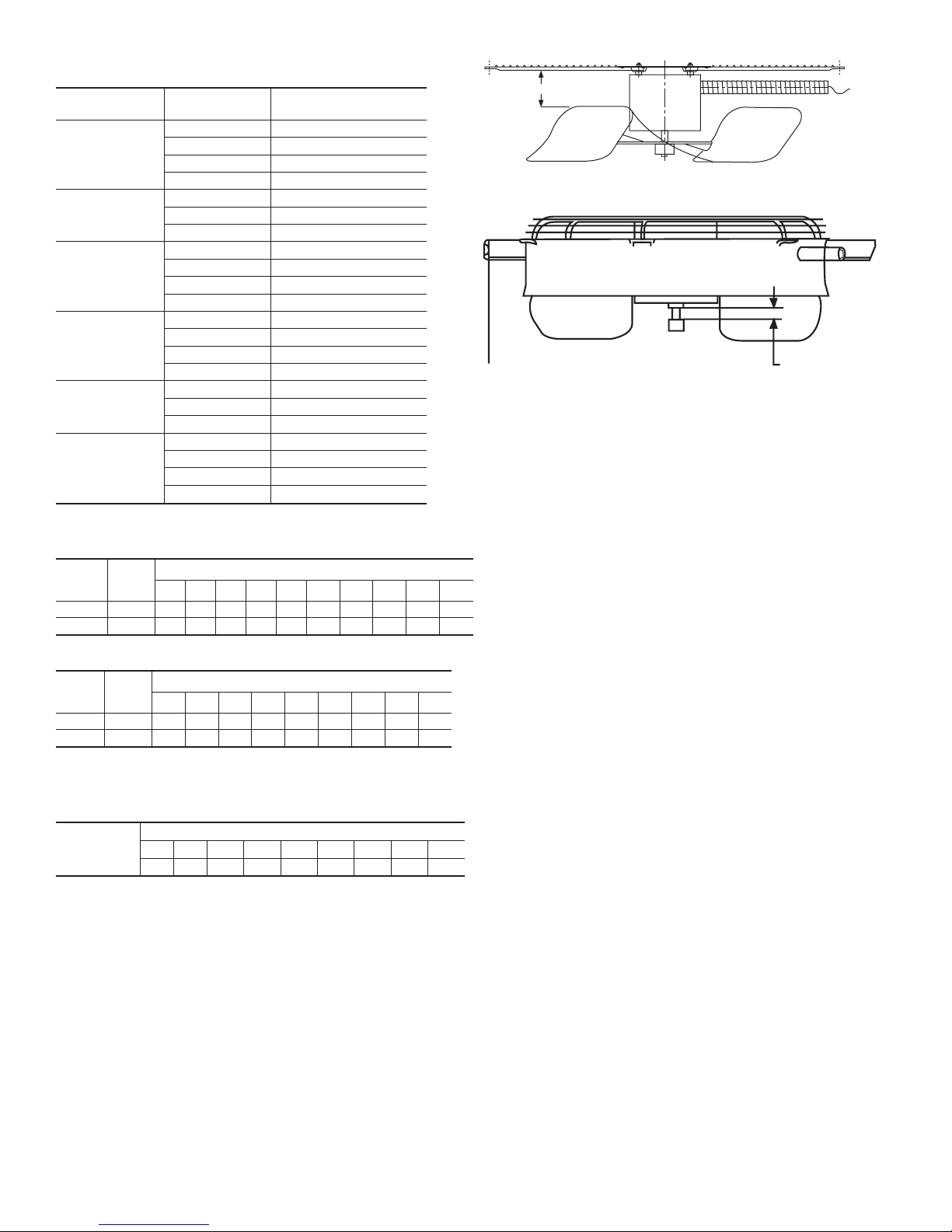
4. Adjust fan height as shown in Fig. 21 or 22.
5. Tighten setscrews.
6. Replace outdoor-fan assembly.
Table 4—Dry Coil Air Delivery* Horizontal Discharge
(Deduct 10 percent for 208 Volt Operation)
230 AND 460 VOLT
Unit Motor Speed Watts/CFM
External Static Pressure (in. wg)
0.1 0.2 0.3 0.4 0.5 0.6 0.7 0.8 0.9
024
Low
Watts 288 285 282 279 274 268 261 - -
Cfm 875 820 802 734 668 582 478 - -
Med
Watts 390 383 378 369 360 350 340 - -
Cfm 1131 1090 1038 978 917 830 721 - -
High
Watts 528 520 510 495 480 460 450 - -
Cfm 1391 1338 1285 1200 1115 1018 920 - -
030
Low
Watts 288 285 282 279 274 268 261 - -
Cfm 875 820 802 734 668 582 478 - -
Med
Watts 390 383 378 369 360 350 340 - -
Cfm 1131 1090 1038 978 917 830 721 - -
High
Watts 528 520 510 495 480 460 450 - -
Cfm 1891 1338 1285 1200 1115 1018 920 - -
036
Low
Watts 450 435 420 400 380 335 326 311 -
Cfm 1231 1218 1204 1120 1008 950 863 751 -
Med
Watts 470 450 445 410 388 359 338 321 -
Cfm 1302 1264 1205 1163 1081 940 873 783 -
High
Watts 660 635 610 575 540 505 485 460 -
Cfm 1700 1660 1581 1450 1297 1190 1095 999 -
042 †
Low
Watts 478 458 440 411 378 350 327 317 -
Cfm 1303 1270 1224 1179 1126 1022 911 816 -
Med
Watts 481 468 450 438 404 370 338 320 -
Cfm 1310 1280 1241 1181 1110 1022 943 811 -
High
Watts - 798 678 647 618 578 540 500 460
Cfm - 1736 1688 1618 1510 1421 1309 1187 1060
048 †
Low
Watts - - 801 760 730 688 650 600 570
Cfm - - 1898 1841 1757 1682 1564 1429 1333
Med
Watts ---------
Cfm ---------
High
Watts - - 870 842 818 782 696 632 628
Cfm - - 2000 1903 1799 1718 1625 1446 1365
060 †
Low
Watts 890 850 810 790 735 680 580 480 422
Cfm 1834 1820 1791 1762 1703 1640 1415 1159 950
Med
Watts 1040 1018 1000 950 890 835 790 650 580
Cfm 2230 2102 2025 1960 1901 1855 1752 1468 1121
High
Watts 1073 1038 1001 958 896 840 800 691 575
Cfm 2230 2202 2160 2122 2052 1926 1791 1588 1202
† 460-v motors are 2-speed.
Air delivery values are based on operating voltage of 230-v. or 460-v., dry coil, without filter or electric heater. Deduct wet coil, filter, and electric heater pressure drops
to obtain external static pressure availabe for ducting.
Do not operate the unit at a cooling airflow that is less than 350 cfm for each 12,000 Btuh of rated cooling capacity. Evaporator coil frosting may occur at airflows below
this point.
Dashes indicate portions of the table that are beyond the blower motor capacity or are not recommended.
17
Page 18
Step 6—Electrical Controls and Wiring
Inspect and check the electrical controls and wiring annually. Be
sure to turn off the electrical power to the unit and install lockout
tag.
Remove the top panel to locate all the electrical controls and
wiring. Check all electrical connections for tightness. Tighten all
screw connections. If any smoky or burned connections are
noticed, disassemble the connection, clean all the parts, restrip the
wire end and reassemble the connection properly and securely.
Check to ensure no wires are touching refrigerant tubing or sharp
sheet metal edges. Move and secure wires to isolate from tubing
and sheet metal edges.
After inspecting the electrical controls and wiring, replace all the
panels. Start the unit, and observe at least one complete cooling
cycle to ensure proper operation. If discrepancies are observed in
operating cycle, or if a suspected malfunction has occurred, check
each electrical component with the proper electrical instrumentation. Refer to the unit wiring label when making these checkouts.
NOTE: Refer to the Sequence of Operation section, as an aid in
determining proper control operation.
Step 7—Refrigerant Circuit
Inspect all refrigerant tubing connections and the unit base for oil
accumulations annually. Detecting oil generally indicates a refrigerant leak.
If oil is detected or if low cooling performance is suspected,
leak-test all refrigerant tubing using an electronic leak-detector, or
liquid-soap solution. If a refrigerant leak is detected, refer to Check
for Refrigerant Leaks section. (See Table of Contents for page
number.)
If no refrigerant leaks are found and low cooling performance is
suspected, refer to Refrigerant Charge. (See Table of Contents for
page number.)
Step 8—Indoor Airflow
The cooling airflow does not require checking unless improper
performance is suspected. If a problem exists, be sure that all
supply- and return-air grilles are open and free from obstructions,
and that the air filter is clean. When necessary, refer to Indoor
Airflow and Airflow Adjustments section to check the system
airflow.
Step 9—Metering Devices
Refrigerant metering devices are fixed orifices and are located in
the inlet header to the indoor and outdoor coils.
Check valves are also located in the liquid lines near the strainers.
The check valves are the smaller of the two components.
Step 10—Lubrication
COMPRESSOR—The compressor is charged with the correct
amount of oil at the factory.
FAN MOTOR BEARINGS—Fan motor bearings are permanently lubricated. No further lubrication of outdoor or indoor fan
motors is required.
Step 11—Liquid Line Strainer
The liquid line strainer (to protect metering device) is made of wire
mesh and is located in the liquid line on the inlet side of the
metering device.
Table 5—Wet Coil Pressure Drop
UNIT SIZE
50ZH
AIRFLOW
(CFM)
PRESSURE DROP
(IN. WG)
024
600 0.02
700 0.05
800 0.06
900 0.07
030
900 0.06
1000 0.06
1200 0.08
036
1000 0.07
1200 0.09
1400 0.11
1600 0.12
042
1000 0.04
1200 0.06
1400 0.08
1600 0.09
048
1400 0.07
1600 0.08
1800 0.09
060
1700 0.07
1800 0.08
2100 0.09
2300 0.10
Table 6—Filter Pressure Drop (in. wg)
UNIT
SIZE
50ZH
FILTER
SIZE
(IN.)
CFM
500 600 700 800 900 1000 1100 1200 1300 1400
024-042 24 x 24 0.06 0.07 0.08 0.08 0.09 0.09 0.09 0.10 0.11 0.12
048, 060 24x30------ - -0.08 0.09
UNIT
SIZE
50ZH
FILTER
SIZE
(IN.)
CFM
1500 1600 1700 1800 1900 2000 2100 2200 2300
024-042 24 x 24 0.14 0.15 -------
048,060 24 x 30 0.10 0.11 0.12 0.13 0.14 0.15 0.16 0.17 0.18
Table 7—Accessory Electric Heat Pressure Drop
(in. wg)
HEATER KW
5-20
CFM
600 800 1000 1200 1400 1600 1800 2000 2200
0.06 0.08 0.10 0.13 0.15 0.18 0.20 0.23 0.25
Fig. 21—Outdoor-Fan Adjustment (024–048 Size)
C00021
3.125 in.
Fig. 22—Outdoor-Fan Adjustment (060 Size)
C02017
0.708in.
18
Page 19
Check valves are also located in the liquid lines near the strainers.
The Strainers are the larger of the two components.
Step 12—High Flow Valves
Located on the compressor hot gas and suction tubes are High
Flow Valves. Large black plastic caps distinguish these valves
with O-rings located inside the caps. These valves can not be
accessed for service in the field. Ensure the plastic caps are in
place and tight or the possibility of refrigerant leakage could occur.
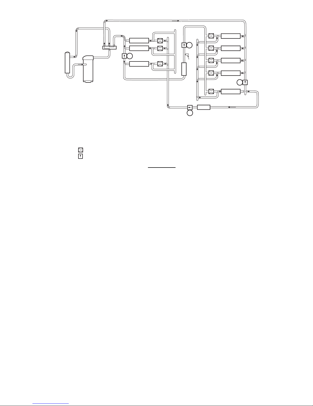
Fig. 23–Typical Heat Pump Operation, Heating Mode
C95045
STRAINER
ACCUMULATOR
COMPRESSOR
STRAINER
LCS
OUTDOOR COIL
INDOOR COIL
A
B
D
C
Check Valves
A
Open
B
Closed
C
Open
D
Closed
LEGEND
LCS Loss of Charge Switch
Acutrol Metering Device
Check Valve (Arrow indicates direction of flow)
HEATING CYCLE
1. Hot gas from compressor flows through the 4-way valve and is
directed to the cooling liquid line check valve. It is then condensed
and directed through subcooling circuits and out to the strainer
and the check valve in the heating liquid line.
2. The refrigerant then feeds the outdoor coil through the Acutrol
metering device on each circuit.
3. Each circuit evaporates the refrigerant and the circuits are combinedintheoutdoorheaderwithsomeofthecircuits flowing through
the check valve.
4. The refrigerant then flows through the 4-way valve, accumulator,
and back to the compressor.
19
Page 20
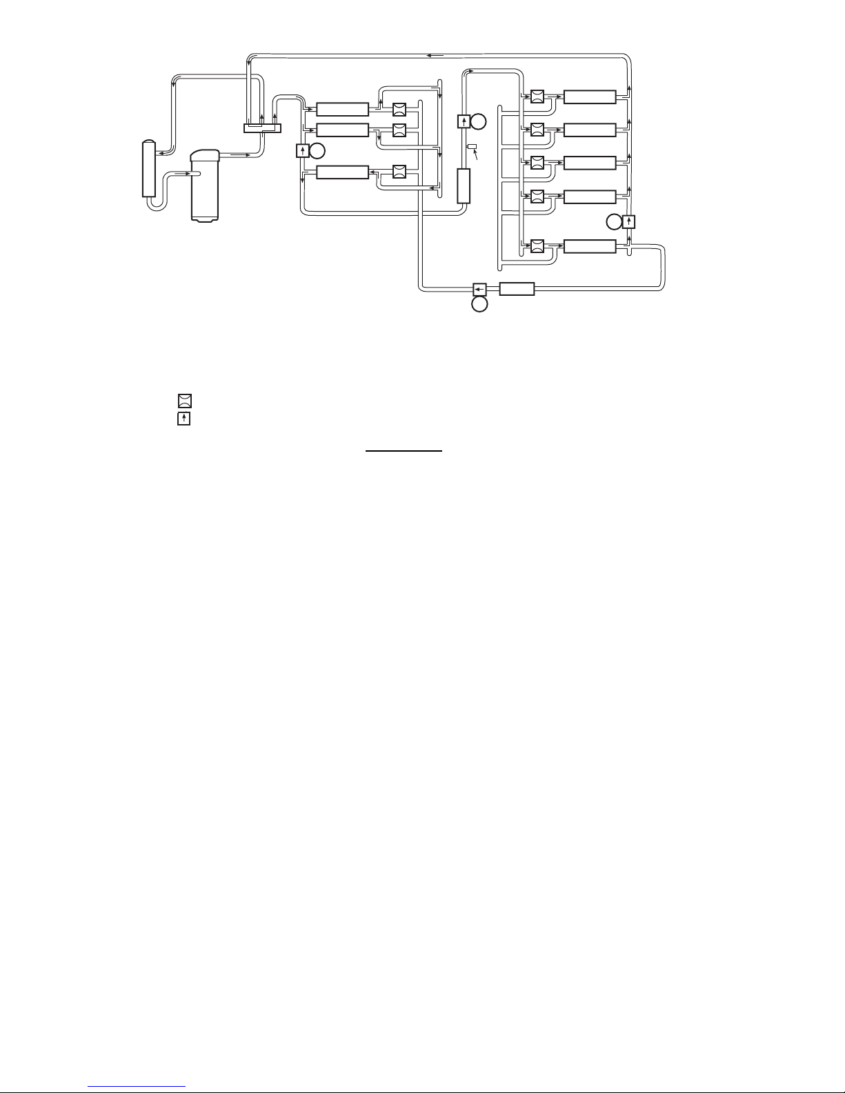
Fig. 24–Typical Heat Pump Operation, Cooling Mode
C95044
STRAINER
ACCUMULATOR
COMPRESSOR
STRAINER
LCS
OUTDOOR COIL
INDOOR COIL
A
B
D
C
Check Valves
A
Closed
B
Open
C
Closed
D
Open
LEGEND
LCS Loss of Charge Switch
Acutrol Metering Device
Check Valve (Arrow indicates direction of flow)
COOLING CYCLE
1. Hot gas from compressor flows through the 4-way valve and is
directed to the heating liquid line check valve. It is then condensedandsubcooledthroughconverging circuits. Refrigerant leaves
the outdoor coil by way of the strainer and the check valve in the
cooling liquid line.
2. The refrigerant then feeds the indoor coil through the Acutrol
metering device on each circuit.
3. Each circuit evaporates the refrigerant and the circuits are combined in the indoor coil header with some of the circuits flowing
through the check valve.
4. The refrigerant then flows through the 4-way valve, accumulator,
and back to the compressor.
20
Page 21
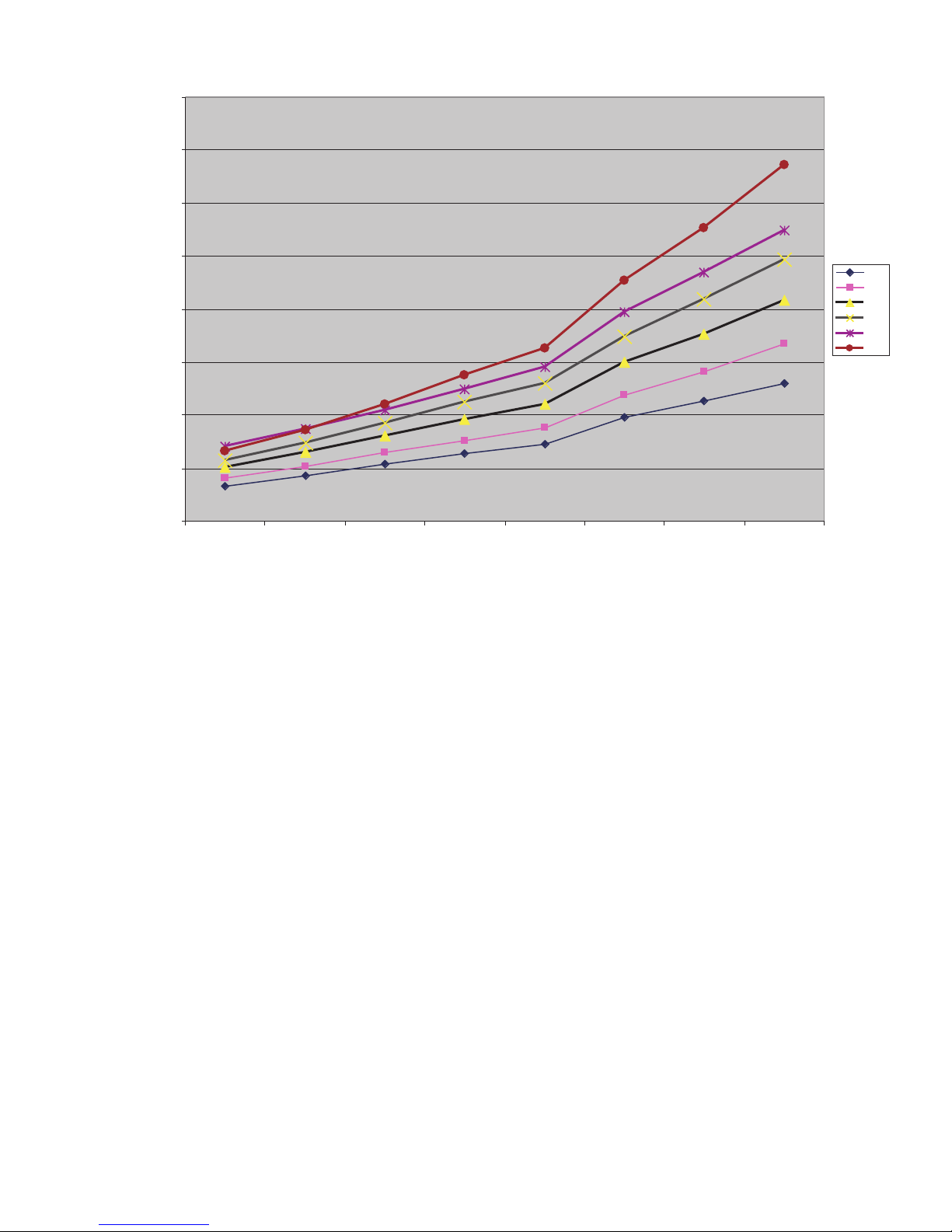
Fig. 25–50ZH Balance Point Chart
C01038
Balance Point Worksheet
0
10000
20000
30000
40000
50000
60000
70000
80000
-100 102030405060
Outdoor Air Temp (Deg F)
024
030
036
042
048
060
Building Heat Loss, BTUH
Unit Integrated Heating Capacity (BTUH)
21
Page 22
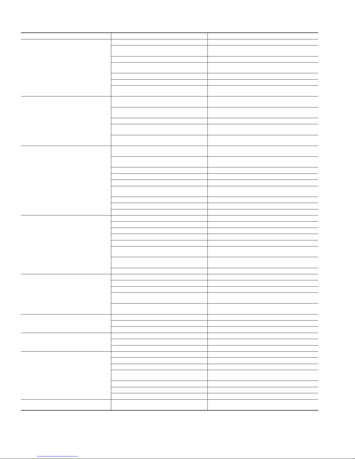
Table 8—Troubleshooting—Cooling and Heating
SYMPTOM CAUSE REMEDY
Compressor and outdoor fan will not start.
Power Failure Call power company
Loss of Charge
Switch open
Evaluate unit for possible refrigerant leak
Fuse blown or circuit breaker tripped Replace fuse or reset circuit breaker
Defective thermostat, contractor, transformer, or
control relay
Replace component
Insufficient line voltage Determine cause and correct
Incorrect or faulty wiring Check wiring diagram and rewire correctly
Thermostat setting too high
Lower thermostat setting below room tempera-
ture
Compressor will not start but outdoor fan
runs.
Faulty wiring or loose connections in compressor
circuit
Check wiring and repair or replace
Compressor motor burned out, seized, or internal
overload open
Determine cause
Replace compressor
Defective run/start capacitor, overload, start relay Determine cause and replace
One leg of 3-phase power dead
Replace fuse or reset circuit breaker
Determine cause
Low input voltage
(20 percent low)
Determine cause and correct
Compressor cycles
(other than normally satisfying thermostat).
Refrigerant overcharge or undercharge
Recover refrigerant, evacuate system, and re-
charge to capacities shown on nameplate
Loss of Charge
Switch open
Evaluate unit for possible refrigerant leak
Defective compressor Replace and determine cause
Insufficient line voltage Determine cause and correct
Blocked outdoor coil (cooling) Determine cause and correct
Defective run/start capacitor, overload or start
relay
Determine cause and replace
Defective thermostat Replace thermostat
Faulty outdoor-fan motor or capacitor Replace
Restriction in refrigerant system Locate restriction and remove
Compressor operates continuously.
Dirty air filter Replace filter
Unit undersized for load Decrease load or increase unit size
Thermostat set too low Reset thermostat
Low refrigerant charge Locate leak, repair, and recharge
Leaking valves in compressor Replace compressor
Frosted outdoor coil with incorrect
defrost operation (heating)
Check defrost time settings. Reset as necessary.
Check defrost temperature switch. Replace as necessary.
Air in refrigerant system
Recover refrigerant, evacuate system, and re-
charge
outdoor coil dirty or restricted Clean coil or remove restriction
Excessive head pressure.
Dirty air filter Replace filter
Dirty outdoor coil Clean coil
Refrigerant overcharged Recover excess refrigerant
Air in refrigerant system
Recover refrigerant, evacuate system, and re-
charge
Outdoor or indoor air restricted
or air is recirculating
Determine cause and correct
Head pressure too low.
Low refrigerant charge Check for leaks, repair and recharge
Compressor valves leaking Replace compressor
Restriction in liquid tube Remove restriction
Excessive suction pressure.
High heat load Check for source and eliminate
Compressor valves leaking Replace compressor
Refrigerant overcharged Recover excess refrigerant
Suction pressure too low.
Dirty air filter (cooling) Replace Filter
Low refrigerant charge Check for leaks, repair, and recharge
Metering device or low side restricted Remove source of restriction
Insufficient indoor airflow (cooling)
Increase air quantity
Check filter- replace if necessary
Temperature too low in conditioned area (cooling) Reset thermostat
Outdoor ambient below 40°F (cooling) Install low-ambient kit
Field-installed filter-drier restricted Replace
Compressor runs but
outdoor fan does not.
Normally closed contacts on
defrost board open
Check condition of relay on board.
Replace board if necessary.
22
Page 23

START-UP CHECKLIST
(REMOVE AND STORE IN JOB FILE)
I. PRELIMINARY INFORMATION
Model No .............................................................................................................................................................
Serial No ..............................................................................................................................................................
Date ......................................................................................................................................................................
Technician ...........................................................................................................................................................
Customer Information(Name/Address) ...........................................................................................................................................................
II. PRE-START-UP
____ Verify that all packing materials have been removed from unit
____ Verify that condensate connection is installed per installation instructions
____ Check all electrical connections and terminals for tightness
____ Check wire proximity to refrigerant tubes and sheet metal edges
____ Check that indoor (indoor) air filter is clean and in place
____ Verify that unit installation is level
____ Check fan wheel propeller for location in housing and setscrew tightness
III. START-UP
Supply Voltage: L1-L2 __________ L2-L3 __________ L3-L1 __________
Compressor Amps: L1(C) __________ L2(S) __________ L3(R) __________
Indoor Fan Amps: __________ Outdoor Fan Amps: __________
TEMPERATURE-Cooling Mode
Outdoor Air Temperature: __________ DB ____________WB
Return-Air Temperature: __________ DB __________ WB
Cooling Supply Air: __________DB___________WB
PRESSURES-Cooling Mode
Refrigerant Suction __________ psig
Suction Line Temp* ___________
Refrigerant Discharge __________ psig
Discharge Temp†__________
TEMPERATURE-Heating Mode
Outdoor Air Temperature: __________ DB ____________WB
Return-Air Temperature: __________ DB __________ WB
Cooling Supply Air: __________DB___________WB
PRESSURES-Heating Mode
Refrigerant Suction __________ psig
Suction Line Temp* ___________
Refrigerant Discharge __________ psig
Discharge Temp†__________
____ Verify Refrigerant charge using charging tables
____ Verify that 3-phase scroll compressor is rotating in correct direction.
*Measured at suction inlet to compressor
†Measured at liquid line leaving outdoor coil
23
Page 24
Copyright 2003 CARRIER Corp. • 7310 W. Morris St. • Indianapolis, IN 46231 50zh5si
Manufacturer reserves the right to discontinue, or change at any time, specifications or designs without notice and without incurring obligations.
Book 1 4
Tab 6 8
PC 101 Catalog No. 535-00080 Printed in U.S.A. Form 50ZH-5SI Pg 24 7-03 Replaces: 50ZH-4SI
 Loading...