

Page 1
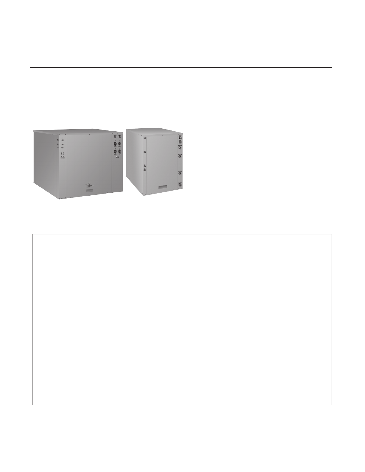
GT-PW Water-to-Water Series (50YER Models)
Installation, Operation and Maintenance Instructions
Residential Water-to-Water
Geothermal Heat Pumps
97B0069N01
Revised 1 July, 2010
Table of Contents
Model Nomenclature 3
General Information 4-5
Storage 5
Pre-Installation 5
Unit Physical Data 6
Dimensional Data 7
Water Connection Installation 8
Ground-Loop Applications 9-10
Ground-Water Applications 11-12
Water Quality Standards 13
Load Side Plumbing Installation 14
Hot Water Generator 15
Hot Water Generator 16
Electrical - Line Voltage 17
Electrical - Low Voltage 18-19
Electrical - Accessories 19
Water Valve Wiring 19
Wiring Diagrams 20-21
CXM Controls 22
Safety Features - CXM Controls 23-24
Unit Commissioning
& Operating Conditions 24
Unit & System Checkout 25
Unit Start Up Procedure 26-27
Operating Pressures 27-28
Preventative Maintenance 29
Refrigeration Troubleshooting Form 30
Warranty 31
Revision History 34
Page 2

Page 3
ClimateMaster Geothermal Heat Pump Systems
Wa t e r - t o -W at e r ( 5 0 Y E R ) S e r i e s - P u r o n
R e v. : 1 J u l y, 2 010
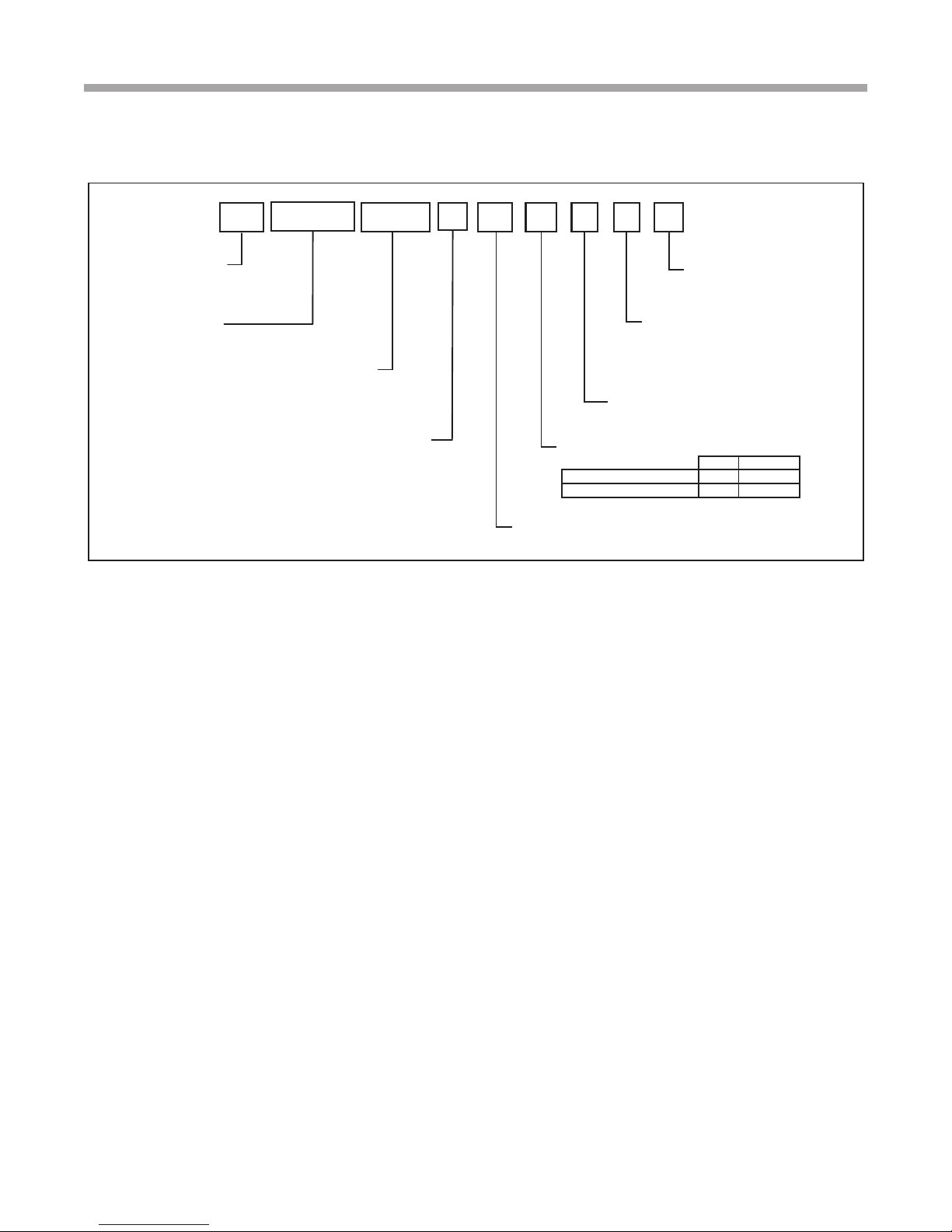
Model Nomenclature
®
5 0
Prefix
Series
YER = Puron Residential
Water-to-Water
Load Heat Exchanger Option
C = Copper
N = Cupro-Nickel
Y E R
Unit Size
036
060
120
0 3 6
C
DC 3 2 1
Packaging
1 = Single Pack, Domestic
Revision Level
1 = Current Revision 036
2 = Current Revision 060, 120
Voltage
3 = 208-230/60/1
Source Heat Exchanger Options
Copper Cupro-Nickel
Without Hot Water Generator C N
Standard D P
Controls
C = CXM
3
Page 4
Wa t e r - t o -W at e r ( 5 0 Y E R ) S e r i e s - P u r o n
R e v. : 1 J u l y, 2 010
General Information
®
Safety
Warnings, cautions and notices appear throughout this
manual. Read these items carefully before attempting any
installation, service or troubleshooting of the equipment.
DANGER: Indicates an immediate hazardous situation, which
if not avoided will result in death or serious injury. DANGER
labels on unit access panels must be observed.
WARNING: Indicates a potentially hazardous situation, which
if not avoided could result in death or serious injury.
CAUTION: Indicates a potentially hazardous situation or an
unsafe practice, which if not avoided could result in minor or
moderate injury or product or property damage.
NOTICE: Notication of installation, operation or
maintenance information, which is important, but which is
not hazard-related.
� WARNING! �
WARNING! To avoid the release of refrigerant into the
atmosphere, the refrigerant circuit of this unit must be
serviced only by technicians who meet local, state, and
federal prociency requirements.
� WARNING! �
WARNING! All refrigerant discharged from this unit must be
recovered WITHOUT EXCEPTION. Technicians must follow
industry accepted guidelines and all local, state, and federal
statutes for the recovery and disposal of refrigerants. If a
compressor is removed from this unit, refrigerant circuit
oil will remain in the compressor. To avoid leakage of
compressor oil, refrigerant lines of the compressor must be
sealed after it is removed.
� CAUTION! �
CAUTION!
these units as a source of heating or cooling during the
construction process. The mechanical components and
lters will quickly become clogged with construction dirt
and debris, which may cause system damage.
To avoid equipment damage, DO NOT use
4
Page 5
Wa t e r - t o -W at e r ( 5 0 Y E R ) S e r i e s - P u r o n
Inspection
Upon receipt of the equipment, carefully check the shipment
against the bill of lading. Make sure all units have been
received. Inspect the carton or crating of each unit, and
inspect each unit for damage. Assure the carrier makes
proper notation of any shortages or damage on all copies of
the freight bill and completes a common carrier inspection
report. Concealed damage not discovered during unloading
must be reported to the carrier within 15 days of receipt of
shipment. If not led within 15 days, the freight company
can deny the claim without recourse. Note: It is the
responsibility of the purchaser to le all necessary
claims with the carrier. Notify your equipment supplier of all
damage within fteen (15) days of shipment.
Storage
Equipment should be stored in its original packaging in a
clean, dry area. Store units in an upright position at all times.
The stack limit for 50YER 036, 060 and 120 is three.
®
R e v. : 1 J u l y, 2 010
General Information
� CAUTION! �
CAUTION! DO NOT store or install units in corrosive
environments or in locations subject to temperature
or humidity extremes (e.g., attics, garages, rooftops,
etc.). Corrosive conditions and high temperature or
humidity can signicantly reduce performance, reliability,
and service life. Always move and store units in an
upright position. Tilting units on their sides may cause
equipment damage.
� CAUTION! �
CAUTION! CUT HAZARD - Failure to follow this caution
may result in personal injury. Sheet metal parts may have
sharp edges or burrs. Use care and wear appropriate
protective clothing, safety glasses and gloves when
handling parts and servicing heat pumps.
Unit Protection
Cover units on the job site with either shipping packaging,
vinyl lm, or an equivalent protective covering. Cap the open
ends of pipes stored on the job site. In areas where painting,
plastering, and/or spraying has not been completed, all
due precautions must be taken to avoid physical damage
to the units and contamination by foreign material. Physical
damage and contamination may prevent proper start-up and
may result in costly equipment clean-up.
Examine all pipes, ttings, and valves before installing any of
the system components. Remove any dirt or trash found in
or on these components.
Pre-Installation
Installation, Operation, and Maintenance instructions are
provided with each unit. The installation site chosen should
include adequate service clearance around the unit. Before
unit start-up, read all manuals and become familiar with the
unit and its operation. Thoroughly check the system before
operation.
Prepare units for installation as follows:
1. Compare the electrical data on the unit nameplate with
ordering and shipping information to verify that the
correct unit has been shipped.
2. Keep the cabinet covered with the shipping packaging
until installation is complete and all plastering, painting,
etc. is nished.
3. Verify refrigerant tubing is free of kinks or dents and that
it does not touch other unit components.
4. Inspect all electrical connections. Connections must be
clean and tight at the terminals.
5
Page 6
Wa t e r - t o -W at e r ( 5 0 Y E R ) S e r i e s - P u r o n
R e v. : 1 J u l y, 2 010
®
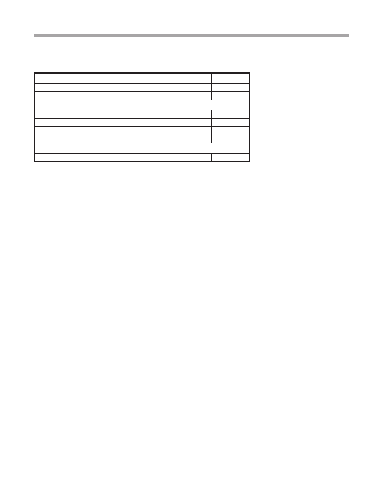
Unit Physical Data
Model 50YER036 50YER060 50YER120
Compressor (qty) Scroll (1) Scroll (2)
Factory Charge HFC-410A (lbs) [kg] Per Circuit 4.5 [2.04] 5.5 [2.49] 5.5 [2.49]
Water Connection Size
Source/Load 1" Swivel 1-1/2 FPT
HWG (in) 1" Swivel 1/2" FPT
Weight - Operating (lbs) [kg] 348 [158] 360 [163] 726 [329]
Weight - Packaged (lbs) [kg] 373 [169] 385 [175] 770 [349]
Water Volume (Source)
Gallons (Liters) 0.96 (3.64) 1.33 (5.04) 2.65 (10.02)
Dual isolated compressor mounting
Balanced port expansion valve (TXV)
Insulated Source and Load Water Coils standard
Insulated Refrigerant Circuit standard
Compressor on (green) and fault (red) light
6
Page 7
1
2
3
4
5
Required
Service Access
Optional
Service Access
B
C
A
1.3
(3.3 cm)
2.7
(6.9 cm)
7.3
(18.5
cm)
(4.3 cm)
(4.3 cm)
Wa t e r - t o -W at e r ( 5 0 Y E R ) S e r i e s - P u r o n
R e v. : 1 J u l y, 2 010
50YER036 - 120
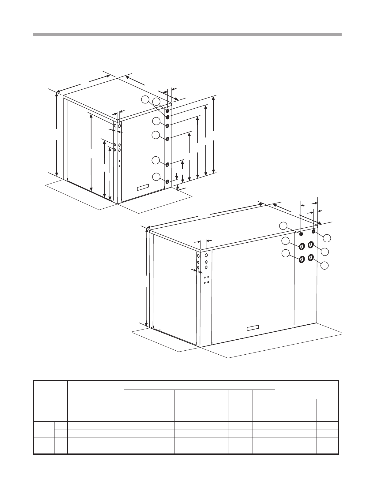
Unit Dimensional Data
®
C
Optional
Service Access
MODEL 036 - 060
B
1.0
(2.5 cm)
M
1.8
1.0
A
5
6
(4.6 cm)
(2.5 cm)
4
3
J
H
G
2
F
Notes:
1. Front & side access is preferred for service
access. However, all components may be
serviced from the front access panel if side
access is not available.
2. While clear access to all removable panels
is not required, installer should take care
to comply with all building codes and allow
adequate clearance for future eld services.
L
K
1
Required
Service Access
E
D
7.3
(18.5
cm)
B
A
1.7
5
1.3
(3.3 cm)
2.7
(6.9 cm)
3
1
6
4
2
Water to
Water
036-060
120
C
Optional
Service Access
MODEL 120
Overall Cabinet
A
DepthBWidthCHeight
in. 30.6 25.4 33 2.7 9.4 19.4 24.5 27.9 30.4 20.9 22.9 30.9
cm. 77.8 64.5 83.8 6.9 23.9 49.3 62.2 70.9 77.2 53.1 58.2 78.5
in. 30.6 52.9 37 25.2 25.2 30.1 30.1 34.9 34.9 29.9 31.9 34.4
cm. 77.8 134.4 94 64.0 64.0 76.5 76.5 88.6 88.6 75.9 81.0 87.4
1 2 3 4 5 6
D
Source
(Outdoor)
Water In
Source
(Outdoor)
Water Out
Water Connections
E
F
Load
(Indoor)
Water In
(Indoor)
Water Out
G
Load
H
HWG
Return In
Required
Service Access
J
HWG
Water
Out
Electric Access Plugs
K
Low
Voltage
L
External
Pump
Power
Supply
M
7
Page 8
Gasket
Swivel Nut
Stainless steel
snap ring
Brass Adaptor
Hand Tighten
Only!
Do Not
Overtighten!
Wa t e r - t o -W at e r ( 5 0 Y E R ) S e r i e s - P u r o n
R e v. : 1 J u l y, 2 010
Unit Installation
®
Unit Location
These units are not designed for outdoor installation. Locate
the unit in an INDOOR area that allows enough space for
service personnel to perform typical maintenance or repairs.
The installation of water source heat pump units and all
associated components, parts and accessories which
make up the installation shall be in accordance with
the regulations of ALL authorities having jurisdiction
and MUST conform to all applicable codes. It is the
responsibility of the Installing Contractor to determine
WATER CONNECTION INSTALLATION
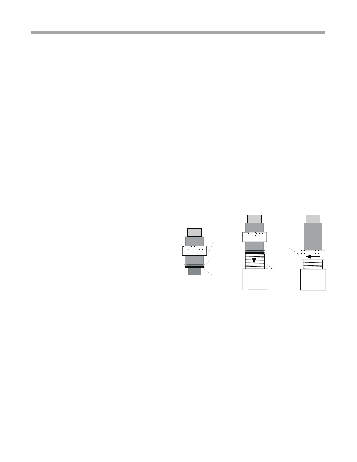
Residential models using swivel piping ttings for water
connections are rated for 450 psi (3101 kPa) operating
pressure. The connections have a rubber gasket seal
similar to a garden hose gasket, which when mated to the
ush end of most 1” threaded male pipe ttings provides
a leak-free seal without the need for thread sealing tape or
joint compound. Insure that the rubber seal is in the swivel
connector prior to attempting any connection (rubber seals
are shipped attached to the swivel connector). DO NOT
OVER TIGHTEN or leaks may occur.
and comply with ALL applicable codes and regulations.
Locate the unit in an indoor area that allows easy removal of
access panels, and has enough space for service personnel
to perform maintenance or repair. Provide sufcient room to
make water and electrical connections.. Any access panel
screws that would be difcult to remove after the unit is
installed should be removed prior to setting the unit. These
units are not approved for outdoor installation and, therefore,
must be installed inside the structure being conditioned.
Do not locate in areas subject to freezing or where humidity
levels can cause cabinet condensation.
The female locking ring is threaded onto the pipe threads
which holds the male pipe end against the rubber gasket,
and seals the joint. HAND TIGHTEN ONLY! DO NOT
OVERTIGHTEN!
FPT Connections (Size 120)
Pipe joint compound is not necessary when Teon threaded
tape is pre-applied to hose assemblies or when ared-end
connections are used. If pipe joint compound is preferred,
use compound only in small amounts on the pipe threads of
the tting adapters. Prevent sealant from reaching the ared
surfaces of the joint.
Note: When anti-freeze is used in the loop, assure that it
is compatible with Teon tape or pipe joint
compound employed.
Maximum allowable torque for brass ttings is 30 ft-lbs [41
N-m]. If a torque wrench is not available, tighten nger-tight
plus one quarter turn. Tighten steel ttings
as necessary.
8
Page 9
Wa t e r - t o -W at e r ( 5 0 Y E R ) S e r i e s - P u r o n
R e v. : 1 J u l y, 2 010
Ground-Loop Heat Pump Applications
®
� CAUTION! �
CAUTION! The following instructions represent industry
accepted installation practices for closed loop earth
coupled heat pump systems. Instructions are provided
to assist the contractor in installing trouble free ground
loops. These instructions are recommendations only.
State/provincial and local codes MUST be followed and
installation MUST conform to ALL applicable codes. It is
the responsibility of the installing contractor to determine
and comply with ALL applicable codes and regulations.
Pre-Installation
Prior to installation, locate and mark all existing underground
utilities, piping, etc. Install loops for new construction before
sidewalks, patios, driveways, and other construction has
begun. During construction, accurately mark all ground loop
piping on the plot plan as an aid in avoiding potential future
damage to the installation.
Piping Installation
All earth loop piping materials should be limited to polyethylene
fusion only for in-ground sections of the loop. Galvanized
or steel ttings should not be used at any time due to their
tendency to corrode. All plastic to metal threaded ttings
should be avoided due to their potential to leak in earth
coupled applications. A anged tting should be substituted.
P/T plugs should be used so that ow can be measured using
the pressure drop of the unit heat exchanger.
Earth loop temperatures can range between 25 and 110°F [-4
to 43°C]. Flow rates between 2.25 and 3 gpm per ton [2.41
to 3.23 l/m per kW] of cooling capacity is recommended in
these applications.
Test individual horizontal loop circuits before backlling.
Test vertical U-bends and pond loop assemblies prior to
installation. Pressures of at least 100 psi [689 kPa] should be
used when testing. Do not exceed the pipe pressure rating.
Test entire system when all loops are assembled.
Flushing the Earth Loop
Once piping is completed between the unit, the ow controller
and the ground loop (Figure 1), the loop is ready for nal
purging and charging. A ush cart with at least a 1.5 hp
[1.1 kW] pump is required to achieve enough uid velocity
in the loop piping system to purge air and dirt particles. An
antifreeze solution is used in most areas to prevent freezing.
All air and debris must be removed from the earth loop piping
before operation. Flush the loop with a high volume of water
at a minimum velocity of 2 fps (0.6 m/s) in all piping. The steps
below must be followed for proper ushing.
1. Fill loop with water from a garden hose through the
ush cart before using the ush cart pump to insure an
even ll.
2. Once full, the ushing process can begin. Do not allow
the water level in the ush cart tank to drop below the
pump inlet line to avoid air being pumped back out to
the earth loop.
3. Try to maintain a uid level in the tank above the return
tee so that air cannot be continuously mixed back into
the uid. Surges of 50 psi (345 kPa) can be used to help
purge air pockets by simply shutting off the return valve
going into the ush cart reservoir. This “dead heads” the
pump to 50 psi (345 kPa). To purge, dead head the pump
until maximum pumping pressure is reached. Open the
return valve and a pressure surge will be sent through the
loop to help purge air pockets from the piping system.
4. Notice the drop in uid level in the ush cart tank when
the return valve is shut off. If air is adequately purged
from the system, the level will drop only 1-2 inches (2.5 5 cm) in a 10” (25 cm) diameter PVC ush tank (about a
half gallon [2.3 liters]), since liquids are incompressible. If
the level drops more than this, ushing should continue
since air is still being compressed in the loop uid.
Perform the “dead head” procedure a number of times.
Note: This uid level drop is your only indication of air
in the loop.
Antifreeze may be added before, during or after the ushing
procedure. However, depending upon which time is chosen,
antifreeze could be wasted when emptying the ush cart
tank. See antifreeze section for more details.
Loop static pressure will uctuate with the seasons.
Pressures will be higher in the winter months than during
the cooling season. This uctuation is normal and should be
considered when charging the system initially. Run the unit in
either heating or cooling for a number of minutes to condition
the loop to a homogenous temperature. This is a good time
for tool cleanup, piping insulation, etc. Then, perform nal
ush and pressurize the loop to a static pressure of 50-75 psi
[345-517 kPa] (winter) or 35-40 psi [241-276 kPa] (summer).
After pressurization, be sure to loosen the plug at the end
of the Grundfos loop pump motor(s) to allow trapped air to
be discharged and to insure the motor housing has been
ooded. This is not required for Taco circulators. Insure that
the Flow Controller provides adequate ow through the
unit by checking pressure drop across the heat exchanger
and compare to the pressure drop tables at the back of the
manual.
Antifreeze
In areas where minimum entering loop temperatures drop
below 40°F [5°C] or where piping will be routed through
areas subject to freezing, antifreeze is required. Alcohols
and glycols are commonly used as antifreeze; however your
local sales manager should be consulted for the antifreeze
best suited to your area. Low temperature protection should
be maintained to 15°F [9°C] below the lowest expected
entering loop temperature. For example, if 30°F [-1°C] is
the minimum expected entering loop temperature, the
9
Page 10
Wa t e r - t o -W at e r ( 5 0 Y E R ) S e r i e s - P u r o n
R e v. : 1 J u l y, 2 010
Ground-Loop Heat Pump Applications
®
leaving loop temperature would be 25 to 22°F [-4 to -6°C]
and low temperature protection should be at 15°F [-10°C].
Calculation is as follows:
30°F - 15°F = 15°F [-1°C - 9°C = -10°C].
All alcohols should be premixed and pumped from a
reservoir outside of the building when possible or introduced
under the water level to prevent fumes. Calculate the total
volume of uid in the piping system using Table 1. Then use
the percentage by volume shown in Table 2 for the amount
of antifreeze needed. Antifreeze concentration should be
checked from a well mixed sample using a hydrometer to
measure specic gravity.
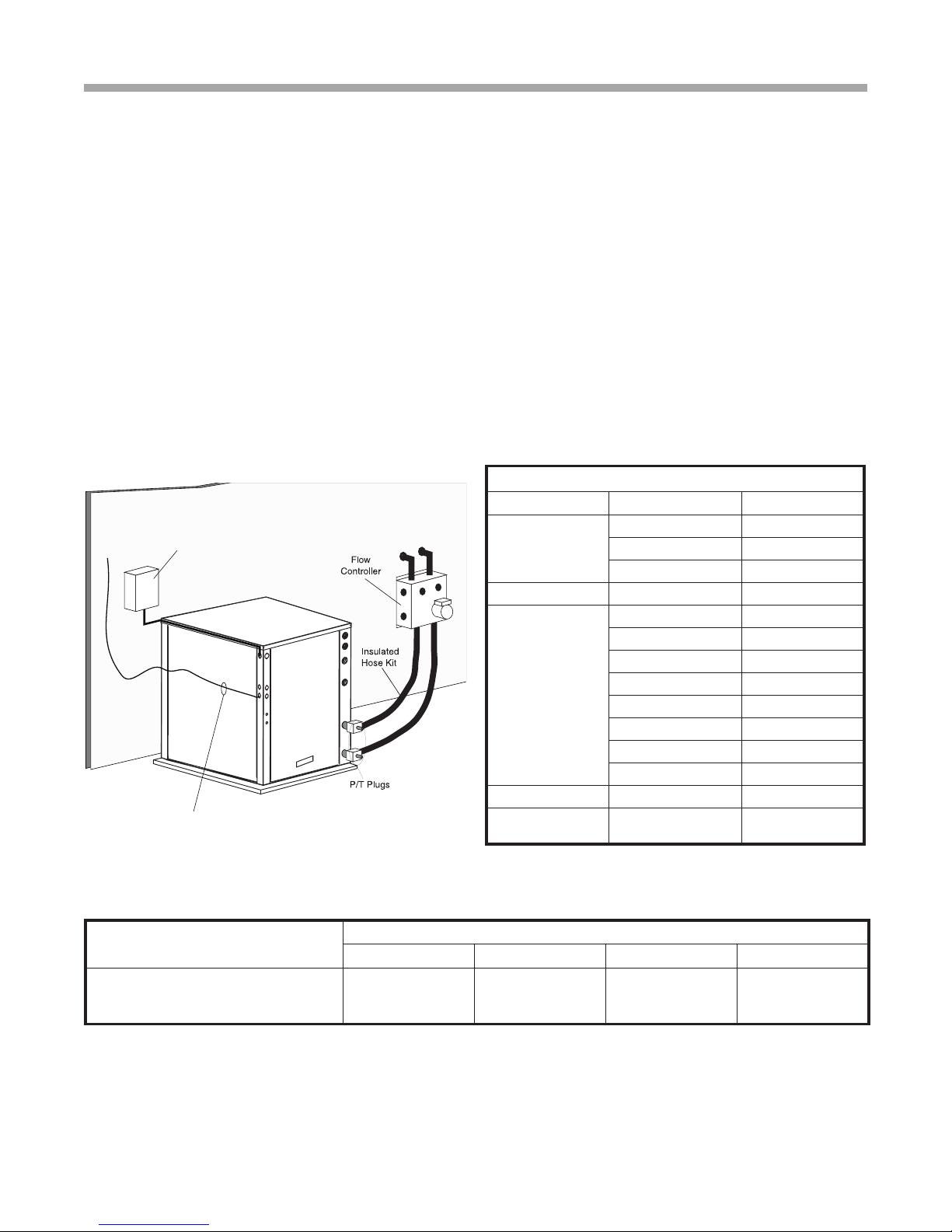
Figure 1: Typical Ground-Loop Application
Unit Power
Disconnect
Air Pad or
Extruded
polystyrene
insulation board
Thermostat Wiring
Low Water Temperature Cutout Setting - CXM Control
When antifreeze is selected, the FP1 jumper (JW3) should
be clipped to select the low temperature (antifreeze 10°F
[-12.2°C]) set point and avoid nuisance faults (see “Low Water
Temperature Cutout Selection” in this manual).
Table 1: Approximate Fluid Volume (gal.) per 100' of Pipe
Fluid Volume (gal [liters] per 100’ [30 meters) Pipe)
Pipe Size Volume (gal) [liters]
1” 4.1 [15.3]
Copper
Rubber Hose 1” 3.9 [14.6]
Polyethylene
Unit Heat Exchanger Typical 1.0 [3.8]
Flush Cart Tank
1.25” 6.4 [23.8]
2.5” 9.2 [34.3]
3/4” IPS SDR11 2.8 [10.4]
1” iPS SDR11 4.5 [16.7]
1.25” IPS SDR11 8.0 [29.8]
1.5” IPS SDR11 10.9 [40.7]
2” IPS SDR11 18.0 [67.0]
1.25” IPS SCH40 8.3 [30.9]
1.5” IPS SCH40 10.9 [40.7]
2” IPS SCH40 17.0 [63.4]
10” Dia x 3ft tall
[254mm x 91.4cm tall]
10 [37.9]
Table 2: Antifreeze Percentages by Volume
Type
Methanol
100% USP food grade Propylene Glycol
Ethanol*
* Must not be denatured with any petroleum based product
10
Minimum Temperature for Low Temperature Protection
10°F [-12.2°C] 15°F [-9.4°C] 20°F [-6.7°C] 25°F [-3.9°C]
25%
38%
29%
21%
25%
25%
16%
22%
20%
10%
15%
14%
Page 11

Wa t e r - t o -W at e r ( 5 0 Y E R ) S e r i e s - P u r o n
R e v. : 1 J u l y, 2 010
Ground-Water Heat Pump Applications
®
Open Loop - Ground Water Systems
Shut off valves should be included for ease of servicing. Boiler
drains or other valves should be “tee’d” into the lines to allow
acid ushing of the heat exchanger. Shut off valves should be
positioned to allow ow through the coaxial heat exchanger
via the boiler drains without allowing ow into the piping
system. P/T plugs should be used so that pressure drop and
temperature can be measured. Piping materials should be
limited to copper or PVC SCH80. Note: Due to the pressure
and temperature extremes, PVC SCH40 is not recommended.
Water quantity should be plentiful and of good quality. Consult
water quality table for guidelines. The unit can be ordered with
either a copper or cupro-nickel water heat exchanger. Consult
table 3 for recommendations. Copper is recommended for
closed loop systems and open loop ground water systems
that are not high in mineral content or corrosiveness. In
conditions anticipating heavy scale formation or in brackish
water, a cupro-nickel heat exchanger is recommended. In
ground water situations where scaling could be heavy or
where biological growth such as iron bacteria will be present,
an open loop system is not recommended. Heat exchanger
coils may over time lose heat exchange capabilities due to
build up of mineral deposits. Heat exchangers must only
be serviced by a qualied technician, as acid and special
pumping equipment is required. Desuperheater coils can
likewise become scaled and possibly plugged. In areas with
extremely hard water, the owner should be informed that the
heat exchanger may require occasional acid ushing. In some
cases, the desuperheater option should not be recommended
due to hard water conditions and additional maintenance
required.
Water Quality Standards
Scaling potential should be assessed using the pH/
Calcium hardness method. If the pH <7.5 and the Calcium
hardness is less than 100 ppm, scaling potential is low. If
this method yields numbers out of range of those listed, the
Ryznar Stability and Langelier Saturation indecies should be
calculated. Use the appropriate scaling surface temperature
for the application, 150°F [66°C] for direct use (well water/
open loop) and HWG (desuperheater); 85°F [29°C] for indirect
use. A monitoring plan should be implemented in these
probable scaling situations. Other water quality issues such
as iron fouling, corrosion prevention and erosion and clogging
should also be considered.
Expansion Tank and Pump
Use a closed, bladder-type expansion tank to minimize
mineral formation due to air exposure. The expansion tank
should be sized to provide at least one minute continuous
run time of the pump using its drawdown capacity rating to
prevent pump short cycling. Discharge water from the unit
is not contaminated in any manner and can be disposed
of in various ways, depending on local building codes (e.g.
recharge well, storm sewer, drain eld, adjacent stream
or pond, etc.). Most local codes forbid the use of sanitary
sewer for disposal. Consult your local building and zoning
department to assure compliance in your area.
The pump should be sized to handle the home’s domestic
water load (typically 5-9 gpm [23-41 l/m]) plus the ow rate
required for the heat pump. Pump sizing and expansion
tank must be chosen as complimentary items. For example,
an expansion tank that is too small can causing premature
pump failure due to short cycling. Variable speed pumping
applications should be considered for the inherent energy
savings and smaller expansion tank requirements.
Water Control Valve
Always maintain water pressure in the heat exchanger by
placing the water control valve(s) on the discharge line
to prevent mineral precipitation during the off-cycle. Pilot
operated slow closing valves are recommended to reduce
water hammer. If water hammer persists, a mini-expansion
tank can be mounted on the piping to help absorb the excess
hammer shock. Insure that the total ‘VA’ draw of the valve
can be supplied by the unit transformer. For instance, a slow
closing valve can draw up to 35VA. This can overload smaller
40 or 50 VA transformers depending on the other controls
in the circuit. A typical pilot operated solenoid valve draws
approximately 15VA. Note the special wiring diagrams later in
this manual for slow closing valves.
Flow Regulation
Flow regulation can be accomplished by two methods. One
method of ow regulation involves simply adjusting the ball
valve or water control valve on the discharge line. Measure the
pressure drop through the unit heat exchanger, and determine
ow rate from tables located later in this manual. Since the
pressure is constantly varying, two pressure gauges may be
needed. Adjust the valve until the desired ow of 1.5 to 2 gpm
per ton [2.0 to 2.6 l/m per kW] is achieved. A second method
of ow control requires a ow control device mounted on
the outlet of the water control valve. The device is typically
a brass tting with an orice of rubber or plastic material
that is designed to allow a specied ow rate. On occasion,
ow control devices may produce velocity noise that can be
reduced by applying some back pressure from the ball valve
located on the discharge line. Slightly closing the valve will
spread the pressure drop over both devices, lessening the
velocity noise. NOTE: When EWT is below 50°F [10°C], a
minimum of 2 gpm per ton (2.6 l/m per kW) is required.
Water Coil Low Temperature Limit Setting
For all open loop systems the 30°F [-1.1°C] FP1 setting
(factory setting-water) should be used to avoid freeze
damage to the unit. See “Low Water Temperature Cutout
Selection” in this manual for details on the low limit setting.
11
Page 12
Wa t e r - t o -W at e r ( 5 0 Y E R ) S e r i e s - P u r o n
R e v. : 1 J u l y, 2 010
®
Ground-Water Heat Pump Applications
� CAUTION! �
CAUTION! Many units are installed with a factory or eld
supplied manual or electric shut-off valve. DAMAGE WILL
OCCUR if shut-off valve is closed during unit operation. A
high pressure switch must be installed on the heat pump
side of any eld provided shut-off valves and connected to
the heat pump controls in series with the built-in refrigerant
circuit high pressure switch to disable compressor
operation if water pressure exceeds pressure switch
setting. The eld installed high pressure switch shall have
a cut-out pressure of 300 psig and a cut-in pressure of
250 psig. This pressure switch can be ordered with a 1/4”
internal are connection as part number 39B0005N02.
� CAUTION! �
CAUTION! Refrigerant pressure activated water regulating
valves should never be used with geothermal heat pump
equipment.
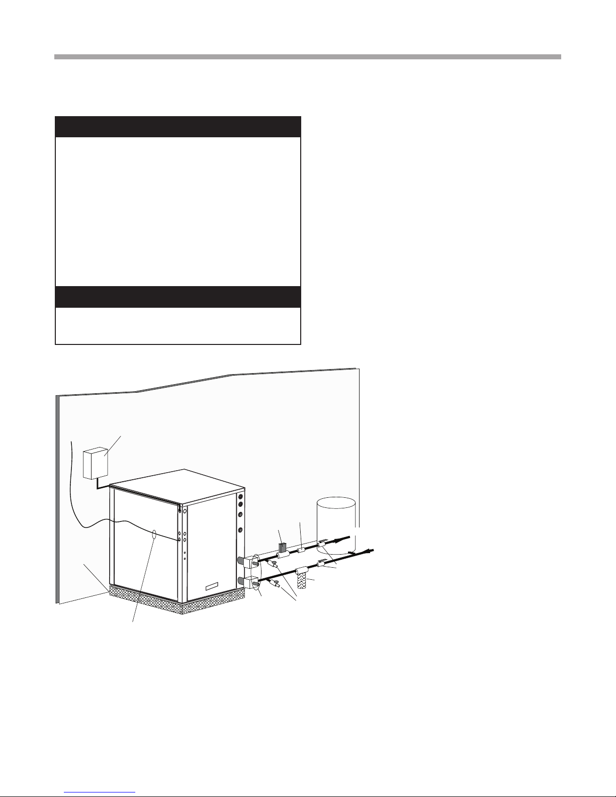
Figure 2: Typical Open Loop/ Well Application
Unit Power
Disconnect
Water
Control
Valve
Air Pad or
Extruded
polystyrene
insulation board
P/T Plugs
Thermostat Wiring
Flow
Regulator
Boiler
Drains
Pressure
Tank
Water Out
Optional
Filter
Shut-Off
Valve
Water In
12
Page 13
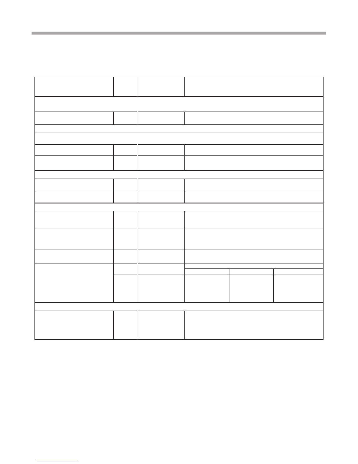
Table 3: Water Quality Standards
Wa t e r - t o -W at e r ( 5 0 Y E R ) S e r i e s - P u r o n
R e v. : 1 J u l y, 2 010
Water Quality Standards
®
WaterQuality
Parameter
HX
Material
Closed
Recirculating
OpenLoopandRecirculatingWell
ScalingPotential-PrimaryMeasurement
Abovethegivenlimits,scalingislikelytooccur.Scalingindexesshouldbecalculatedusingthelimitsbelow
pH/CalciumHardness
Method
All
pH<7.5andCaHardness<100ppm
IndexLimitsforProbableScalingSituations-(Operationoutsidetheselimitsisnotrecommended)
Scalingindexesshouldbecalculatedat150∞F[66∞C]fordirectuseandHWGapplications,andat90∞F[32∞C]forindirectHXuse.
Amonitoringplanshouldbeimplemented.
Ryznar
StabilityIndex If>7.5minimizesteelpipeuse.
Langelier
SaturationIndex
All
All
- 6.0-7.5
-
If<-0.5minimizesteelpipeuse.Basedupon150∞F[66∞C]HWGand
-0.5to+0.5
Directwell,85∞F[29∞C]IndirectWellHX
IronFouling
IronFe2+(Ferrous)
(BacterialIronpotential)
IronFouling
All
All
-
2+
(ferrous)>0.2ppmwithpH6-8,O2<5ppmcheckforironbacteria
IfFe
-
Abovethisleveldepositionwilloccur.
<0.2ppm(Ferrous)
<0.5ppmofOxygen
CorrosionPrevention
pH
HydrogenSulfide(H
Ammoniaionashydroxide,chloride,
nitrateandsulfatecompounds
Maximum
ChlorideLevels
S)
2
6-8.5
All
All
All
Copper - <20ppm NR NR
CuproNickel - <150ppm NR NR
304SS - <400ppm <250ppm <150 ppm
316SS - <1000ppm <550ppm < 375 ppm
Titanium - >1000ppm >550ppm >375 ppm
Monitor/treatas
needed
- <0.5ppm
-
Minimizesteelpipebelow7andnoopentankswithpH<8
AtH
S>0.2ppm,avoiduseofcopperandcoppernickelpipingorHX's.
2
Copperalloy(bronzeorbrass)castcomponentsareOKto<0.5ppm.
50°F(10°C) 75°F(24°C) 100°F (38°C)
Rotteneggsmellappearsat0.5ppmlevel.
MaximumAllowableatmaximumwatertemperature.
6-8.5
<0.5ppm
ErosionandClogging
<10ppmofparticles
andamaximum
velocityof6fps[1.8m/s].
ParticulateSizeand
Erosion
Notes:
• Closed Recirculating system is identified by a
• Recirculating open wells should observe the open recirculating design considerations.
• NR - Application not recommended.
• "-" No design Maximum.
All
Filteredformaximum
800micron[800mm,
20mesh]size.
closed pressurized piping system.
<10ppm(<1ppm"sandfree"forreinjection)ofparticlesandamaximum
velocityof6fps[1.8m/s].Filteredformaximum800micron[800mm,
20mesh]size.Anyparticulatethatisnotremovedcanpotentially
clogcomponents.
Rev.: 6/2/2010
13
Page 14

Wa t e r - t o -W at e r ( 5 0 Y E R ) S e r i e s - P u r o n
R e v. : 1 J u l y, 2 010
Load Side Plumbing Installation
®
50YER Unit Load Plumbing
The applications are too varied to describe in this document.
However, some basic guidelines will be presented. Much of the
discussions on water loop applications would be valid for the
load plumbing discussion as well. All plumbing should conform
to local codes with the following considerations:
Wide temperature variation applications such as heating/
cooling coils:
- Employ piping materials that are rated for the maximum
temperature and pressure combination. This excludes
PVC for most heating applications.
- Insure that load water ow in high temperature heating
applications is at least 3 gpm per ton [3.9 l/m per kW]
to improve performance and reduce nuisance high
pressure faults.
- DO NOT employ plastic to metal threaded joints
- Utilize a pressure tank and air separator vent system to
equalize pressure and remove air.
Swimming Pool Hot Tub Applications:
- Load coax should be isolated with secondary heat
exchanger constructed of anti-corrosion material in all
chlorine/bromine uid applications.
Potable Water Applications:
- Load coax material should always be vented double
walled for use in potable water systems.
- Insure load water ow in high temperature heating
applications is at least 3 gpm per ton to improve
performance and reduce nuissance to high pressure
faults.
NOTE: It is strongly recommended that all piping
connections, both internal and external to the unit,
be pressure tested by an appropriate method prior
to any nishing of the interior space or before
access to all connections is limited. Test pressure
may not exceed the maximum allowable pressure
for the unit and all components within the water
system. The heat pump manufacturer will not be
responsible or liable for damages from water leaks
due to inadequate or lack of a pressurized leak test,
or damages caused by exceeding the maximum
pressure rating during installation.
14
Page 15

Hot Outlet
to home
Powered
Water
Heater
Upper
element to
120 - 130°F
[49 - 54°C]
Lower
element to
100 - 110°F
[38 - 43°C]
Cold Inlet from
Domestic supply
Shut-off
Valve #4
Shut-off
Valve #3
Shut Off
Valve #2
Shut-off
Valve #1
Insulated water lines 5/8” OD, 50 ft maximum (one way) meters
[16mm OD, 15 meters maximum]
Insulated water lines - 5/8” OD, 50 ft maximum (one way)
[16mm OD, 15 meters maximum]
Upper element to 130°F [54°C]
(or owner preference)
Cold Inlet
Hot Outlet to
house
Powered
Water Heater
Cold Inlet from
Domestic supply
Hot Outlet
Unpowered
Water Heater
Field Supplied 3/4” brass nipple and “T”
Lower element to 120°F [49°C]
Shut-off
Valve #1
Shut-off
Valve #4
Shut-off
Valve #3
Shut Off
Valve #2
Wa t e r - t o -W at e r ( 5 0 Y E R ) S e r i e s - P u r o n
R e v. : 1 J u l y, 2 010
Hot Water Generator
®
The HWG (Hot Water Generator) or desuperheater option
provides considerable operating cost savings by utilizing
excess heat energy from the heat pump to help satisfy
domestic hot water requirements. The HWG is active
throughout the year, providing virtually free hot water when
the heat pump operates in the cooling mode or hot water at
the COP of the heat pump during operation in the heating
mode.
Heat pumps equipped with the HWG option include a builtin water to refrigerant heat exchanger that eliminates the
need to tie into the heat pump refrigerant circuit in the eld.
The control circuit and pump are also built in for residential
equipment. Figure 3 shows a typical example of HWG water
piping connections on a unit with built-in pump. This piping
layout minimizes scaling potential.
Electric water heaters are recommended. If a gas, propane,
or oil water heater is used, a second preheat tank should
be considered (Figure 4). Also, if the electric water heater
has only a single center element, the dual tank system is
recommended to insure a usable entering water temperature
for the HWG.
Figure 3: Typical HWG Installation
Typically a single tank of at least 52 gallons (235 liters) is used
to limit installation costs and space. However, a dual tank, as
shown in Figure 4, is the most efcient system, providing the
maximum storage and temperate source water to the HWG.
It is always advisable to use water softening equipment on
domestic water systems to reduce the scaling potential and
lengthen equipment life. In extreme water conditions, it may
be necessary to avoid the use of the HWG option since the
potential cost of frequent maintenance may offset or exceed
any savings.
HFC-410A systems inherently have a lower hot gas
temperature than R-22 systems because the equipment is
more efcient (i.e. less waste heat is available). It is possible
that energy could be transferred from the water heater to
the hot gas line instead of from the hot gas line to the water
heater during certain times of the year. To prevent this from
occurring, a temperature switch will deactivate the pump
at those conditions that typically occur in the cooling mode
with low entering water temperatures.
Figure 4: HWG Double Tank Installation
15
Page 16

Wa t e r - t o -W at e r ( 5 0 Y E R ) S e r i e s - P u r o n
R e v. : 1 J u l y, 2 010
Hot Water Generator
®
Installation
The HWG high limit temperature switch is set at 125°F
[52°C] and is located on the HWG heat exchanger “Water In”
line. If the HWG is connected incorrectly or if circulation is
reversed, the aquastat will sense leaving water temperature
and prevent HWG operation. UNDER NO CIRCUMSTANCES
SHOULD THE LIMIT BE DISCONNECTED OR REMOVED!
Full load conditions could drive hot water tank temperatures
far above safe temperature levels if the aquastat has been
disconnected or removed.
The heat pump, water piping, pump, and hot water tank
should be located where the ambient temperature is not
subject to freezing. Keep water piping lengths at a minimum.
DO NOT use a one way length greater than 50 ft. [15 m].
All installations must be in accordance with local codes. The
installer is responsible for knowing the local requirements,
and for performing the installation accordingly. DO NOT
connect the pump wiring until “Initial Start-Up” section,
below. Powering the pump before all installation steps are
completed may damage the pump.
Water Tank Preparation
1. Turn off power or fuel supply to the hot water tank.
2. Connect a hose to the drain valve on the water tank.
3. Shut off the cold water supply to the water tank.
4. Open the drain valve and open the pressure relief valve
or a hot water faucet to drain tank.
5. When using an existing tank, it should be ushed with
cold water after it is drained until the water leaving the
drain hose is clear and free of sediment.
6. Close all valves and remove the drain hose.
7. Install HWG water piping.
4. Inspect all work for leaks.
5.
Before restoring power or fuel supply to the water heater,
adjust the temperature setting on the tank thermostat(s)
to insure maximum utilization of the heat available from
the refrigeration system and conserve the most energy.
On tanks with both upper and lower elements and
thermostats, the lower element should be turned down
to 100°F [38°C] or the lowest setting; the upper element
should be adjusted to 120-130°F [49-54°C]. Depending
upon the specic needs of the customer, you may want
to adjust the upper element differently. On tanks with a
single thermostat, a preheat tank should be used (Fig 4).
6. Replace access cover(s) and restore power or
fuel supply.
Initial Start-Up
1. Make sure all valves in the HWG water circuit are
fully open.
2. Turn on the heat pump and allow it to run for
10-15 minutes.
3. Turn the heat pump and heat pump power supply “OFF”
and CONNECT POWER TO THE HWG PUMP as shown
in the unit wiring diagram. Connect the pump power lead
as instructed on the tag attached to the pump wiring.
4. The HWG pump should not run if the compressor is not
running.
5. The temperature difference between the water entering
and leaving the HWG coil should be approximately
5-10°F [3-6°C].
6. Allow the unit to operate for 20 to 30 minutes to insure
that it is functioning properly.
HWG Water Piping
1. Using at least 5/8” [16mm] O.D. copper, route and
install the water piping, valves and air vent as shown
in Figures 3 or 4. An appropriate method must be
employed to purge air from the HWG piping. This may be
accomplished by ushing water through the HWG (as In
Figures 3 or 4).
2. Insulate all HWG water piping with no less than 3/8”
[10mm] wall closed cell insulation.
3. Open both shut off valves and make sure the tank drain
valve is closed.
Water Tank Rell
1. Close valve #4. Ensure that the HWG valves (valves #2
and #3) are open. Open the cold water supply (valve #1)
to ll the tank through the HWG piping. This will purge air
from the HWG piping.
2. Open a hot water faucet to vent air from the system until
water ows from faucet; turn off faucet. Open valve #4.
3.
Depress the hot water tank pressure relief valve handle to
ensure that there is no air remaining in the tank.
16
Page 17
Wa t e r - t o -W at e r ( 5 0 Y E R ) S e r i e s - P u r o n
R e v. : 1 J u l y, 2 010
Electrical - Line Voltage
®
� CAUTION! �
Use only copper conductors for eld installed electrical
wiring. Unit terminals are not designed to accept other
types of conductors.
General Line Voltage Wiring
Be sure the available power is the same voltage and
phase as that shown on the unit serial plate. Line and
low voltage wiring must be done in accordance with
local codes or the National Electric Code, whichever is
applicable.
Power Connection
Line voltage connection is made by connecting the
incoming line voltage wires to the power distribution
block, or compressor contactor, refer to unit wiring
diagram. Consult the electrical data table (Table 4) for
correct fuse size.
208 Volt Operation
The units are factory wired for 230 Volt. The transformer
may be switched to 208V operation as illustrated on
the wiring diagram by switching the Red (208V) and the
Orange (230V) at the contactor terminal L1.
� WARNING! �
Disconnect electrical power source to prevent injury or
death from electrical shock.
� WARNING! �
To avoid possible injury or death due to electrical shock,
open the power supply disconnect switch and secure it in
an open position during installation.
All eld installed wiring, including electrical ground,
must comply with the National Electrical Code as well
as all applicable local codes.
Refer to the unit wiring diagrams and electrical data
table (Table 4) for fuse sizes and a schematic of the
eld connections which must be made by the installing
(or electrical) contractor.
Consult the unit wiring diagram located on the inside
of the compressor access panel to ensure proper
electrical hookup.
be made with a length of exible conduit to minimize
vibration and sound transmission to the building.
All nal electrical connections must
17
Page 18
Wa t e r - t o -W at e r ( 5 0 Y E R ) S e r i e s - P u r o n
R e v. : 1 J u l y, 2 010
Electrical Data
Table 4: 50YER Electrical Data
®
Model
036 3 208-230/60/1 187/254 1 16.7 79 0.4 4 16.7 20.8 35
060 3 208-230/60/1 187/254 1 26.3 134 0.4 4 26.3 32.9 50
120 3 208-230/60/1 187/254 2 26.3 134 0.4 4 52.6 59.2 80
HACR circuit breaker in USA only
Residential units come standard with 75VA transformer, HWG pump, and HWG connections
Voltage
Code
Voltage
Min/Max
Voltage
Compressor
QTY RLA LRA
HWG
Pump
FLA
EXT Loop
Pump
FLA
Total
Unit
FLA
Min
Circuit
Amps
Electrical - Low Voltage
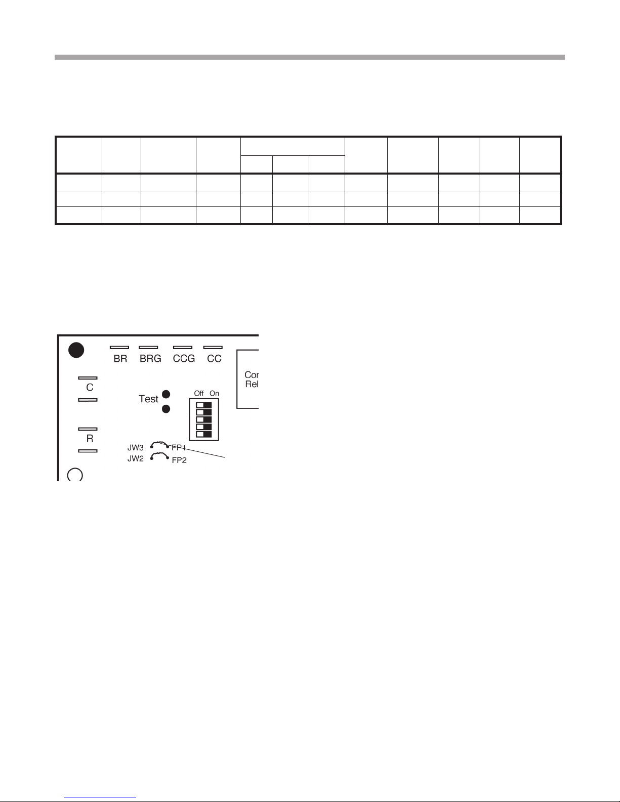
Changing FP1-Low Water Temperature
Cutout Setpoint
JW3-FP1 jumper
should be
clipped when
antifreeze is
CXM PCB
used.
Low Water Temperature Cutout Selection
The CXM control allows the eld selection of low water (or
water-antifreeze solution) temperature limit by clipping jumper
JW3, which changes the sensing temperature associated with
thermistor FP1. Note that the FP1 thermistor is located on
the refrigerant line between the coaxial heat exchanger and
expansion device (TXV). Therefore, FP1 is sensing refrigerant
temperature, not water temperature, which is a better indication
of how water ow rate/temperature is affecting the refrigeration
circuit.
The factory setting for FP1 is for systems using water (30°F
[-1.1°C] refrigerant temperature). In low water temperature
(extended range) applications with antifreeze (most ground
loops), jumper JW3 should be clipped as shown in Figure
19 to change the setting to 10°F [-12.2°C] refrigerant
temperature, a more suitable temperature when using
an antifreeze solution. All residential units include water/
refrigerant circuit insulation to prevent internal condensation,
which is required when operating with entering water
temperatures below 59°F [15°C].
Max
Fuse/
HACR
18
Page 19
Wa t e r - t o -W at e r ( 5 0 Y E R ) S e r i e s - P u r o n
R e v. : 1 J u l y, 2 010
Electrical - Low Voltage Wiring
®
Accessory Connections
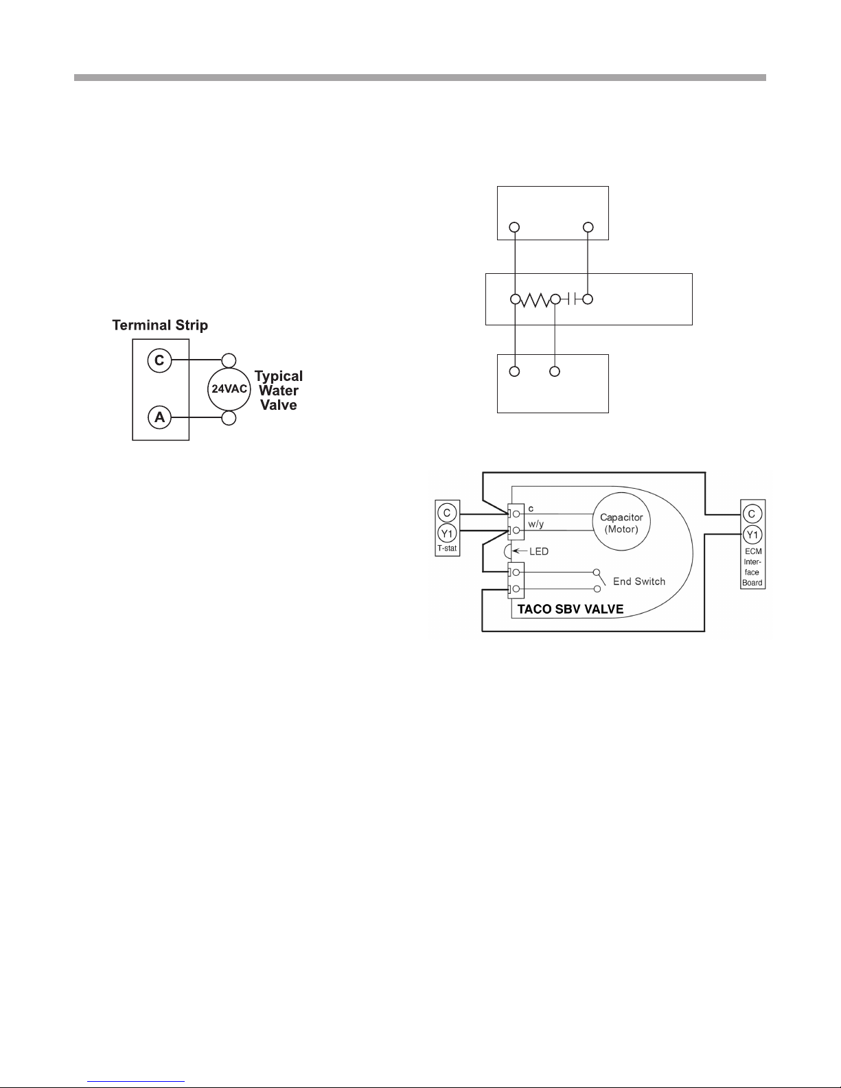
A terminal paralleling the compressor contactor coil has been
provided on the CXM control. Terminal “A” is designed to
control accessory devices, such as water valves. Note: This
terminal should be used only with 24 Volt signals and not
line voltage. Terminal “A” is energized with the compressor
contactor. See Figure 5 or the specic unit wiring diagram for
details.
Figure 5: Accessory Wiring
Water Solenoid Valves
An external solenoid valve(s) should be used on ground
water installations to shut off ow to the unit when the
compressor is not operating. A slow closing valve may be
required to help reduce water hammer. Figure 5 shows
typical wiring for a 24VAC external solenoid valve. Figures
6 or 7 illustrate typical slow closing water control valve
wiring for Taco 500 series (ClimateMaster P/N AVM…)
and Taco SBV series valves. Slow closing valves take
approximately 60 seconds to open (very little water will ow
before 45 seconds). Once fully open, an end switch allows
the compressor to be energized. Only relay or triac based
electronic thermostats should be used with slow closing
valves. When wired as shown, the slow closing valve will
operate properly with the following notations:
Figure 6: AVM Valve Wiring
C
2
1
Heater Switch
C
Y1
3
Y1
Thermostat
Figure 7: Taco SBV Valve Wiring
AVM
Taco Valve
1. The valve will remain open during a unit lockout.
2. The valve will draw approximately 25-35 VA through the
“Y” signal of the thermostat.
Note: This valve can overheat the anticipator of an
electromechanical thermostat. Therefore, only relay or
triac based thermostats should be used.
19
Page 20
Wa t e r - t o -W at e r ( 5 0 Y E R ) S e r i e s - P u r o n
R e v. : 1 J u l y, 2 010
®
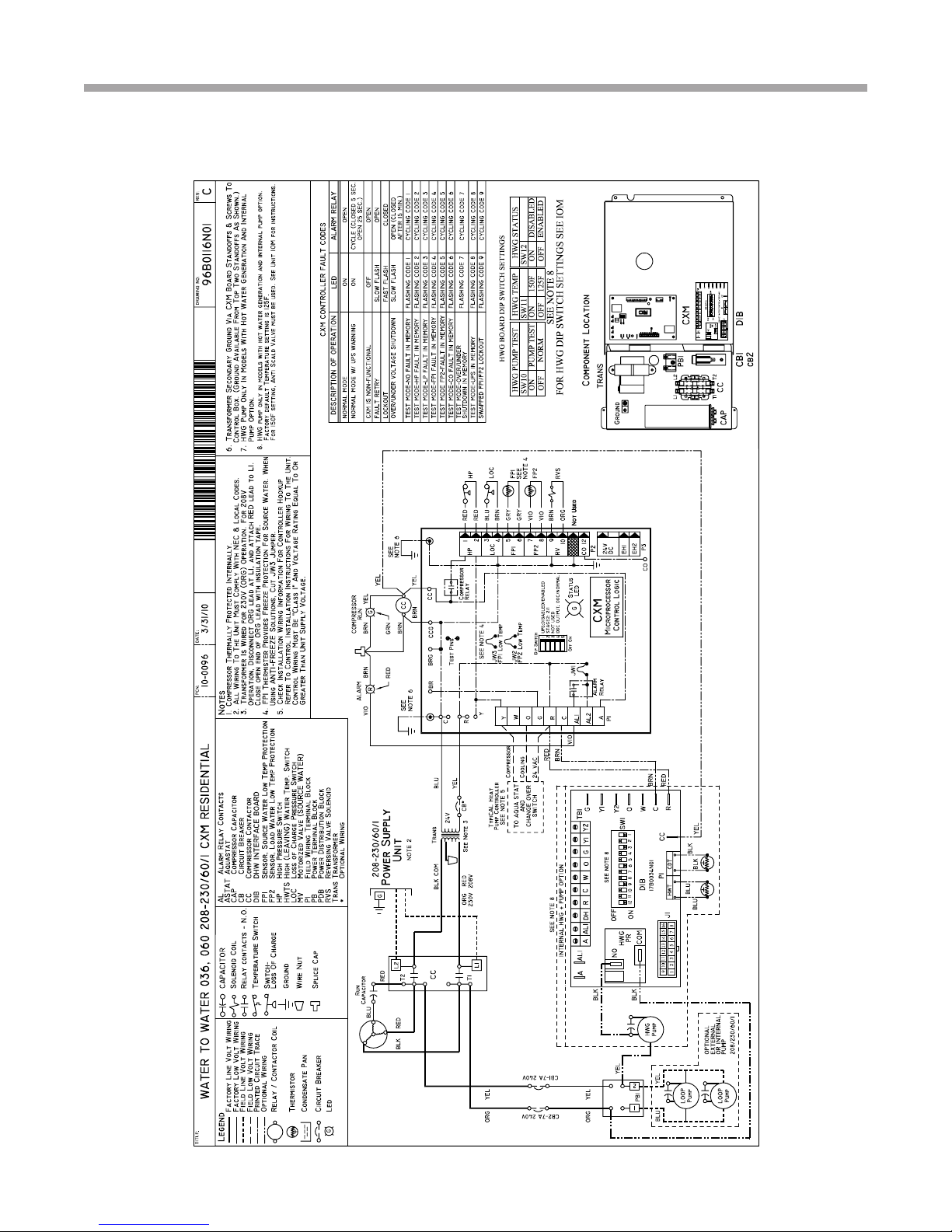
50YER036 & 50YER060 Electrical Wiring Diagram - 96B0116N01
20
Page 21
Wa t e r - t o -W at e r ( 5 0 Y E R ) S e r i e s - P u r o n
R e v. : 1 J u l y, 2 010
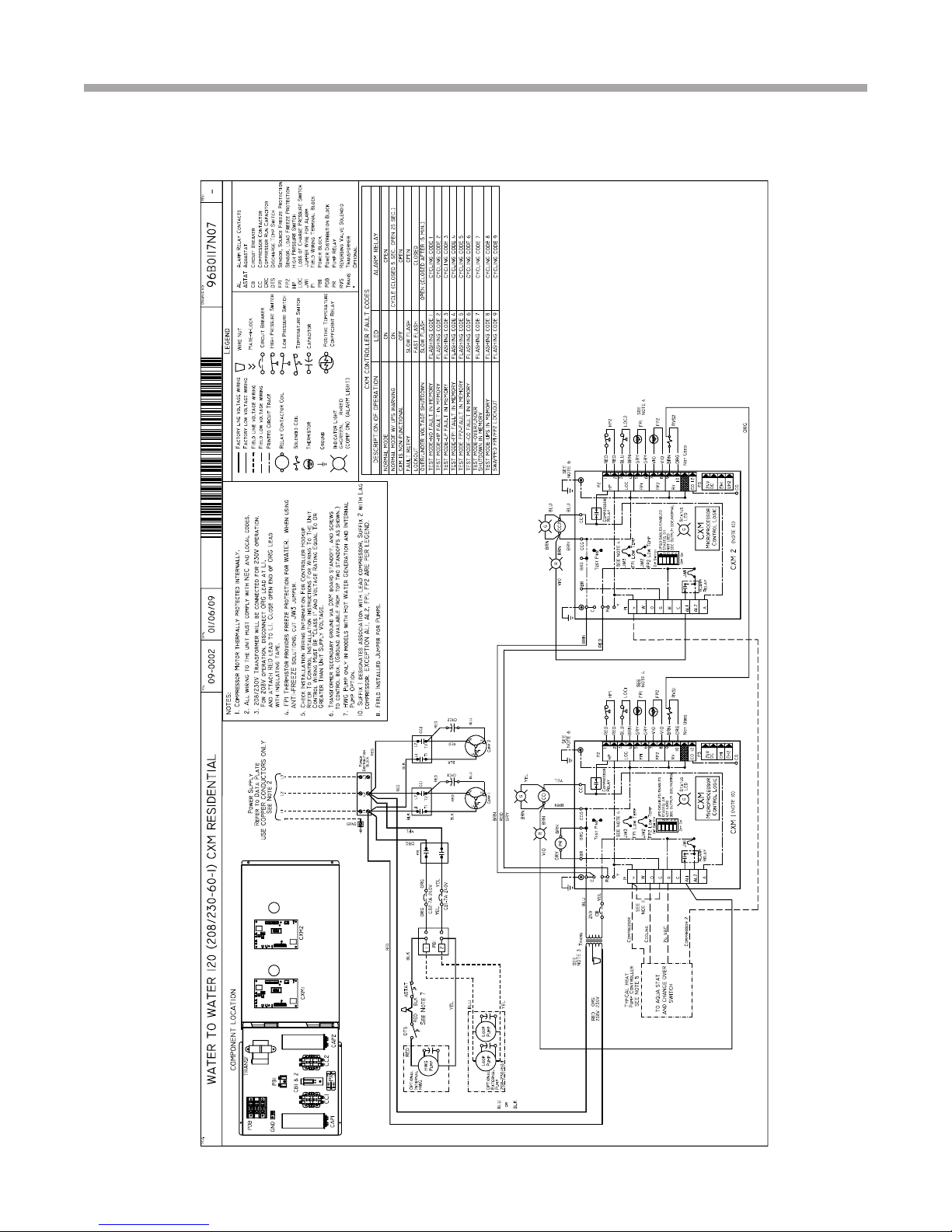
50YER120 Electrical Wiring Diagram - 96B0117N07
®
21
Page 22
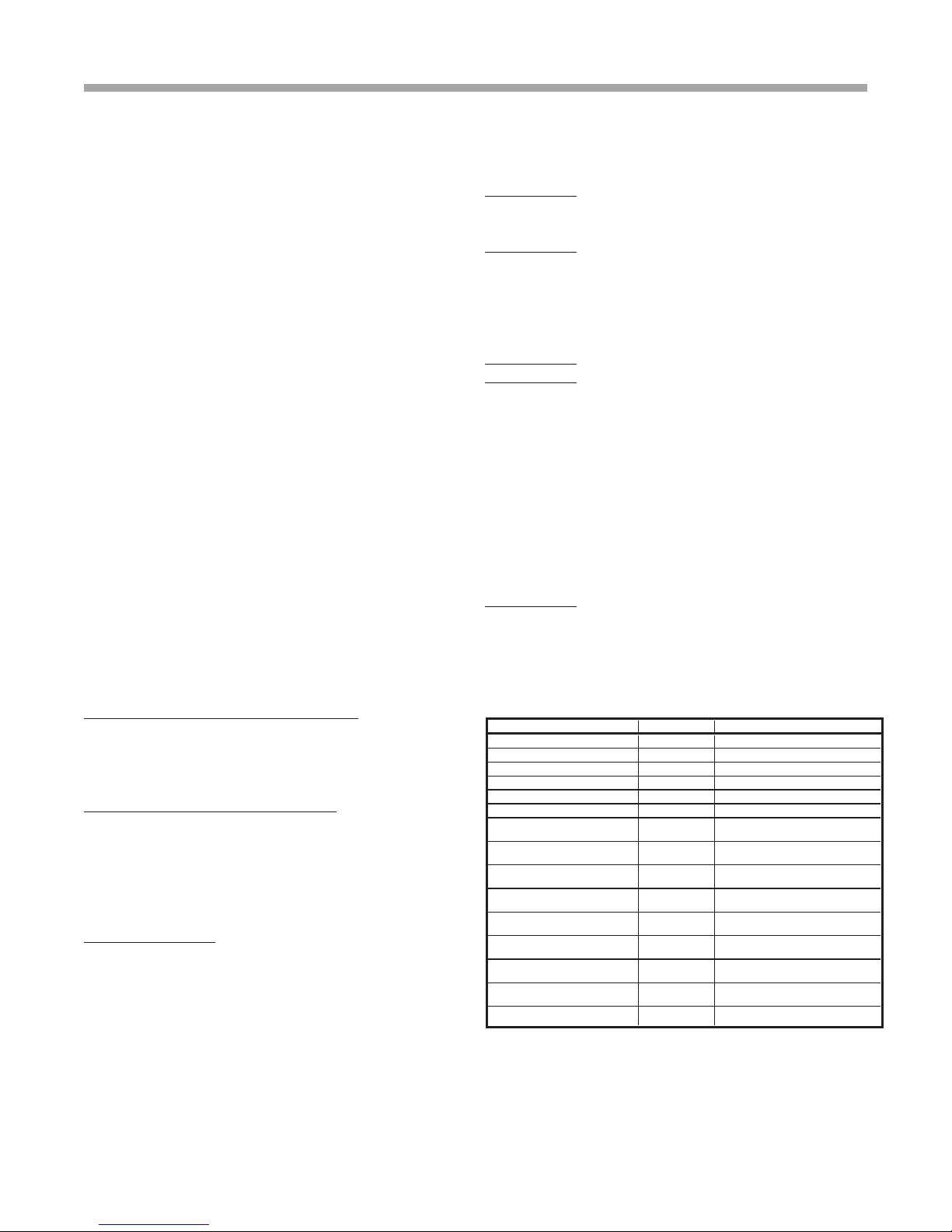
Description of Operation LED Alarm Relay
Normal Mode On Open
Normal Mode with UPS Warning On Cycle (closed 5 sec., Open 25 sec.)
CXM is non-functional Off Open
Fault Retry Slow Flash Open
Lockout Fast Flash Closed
Over/Under Voltage Shutdown Slow Flash Open (Closed after 15 minutes)
Test Mode - No fault in memory Flashing Code 1 Cycling Code 1
Test Mode - HP Fault in memory Flashing Code 2 Cycling Code 2
Test Mode - LP Fault in memory Flashing Code 3 Cycling Code 3
Test Mode - FP1 Fault in memory Flashing Code 4 Cycling Code 4
Test Mode - FP2 Fault in memory Flashing Code 5 Cycling Code 5
Test Mode - CO Fault in memory Flashing Code 6 Cycling Code 6
Test Mode - Over/Under
shutdown in memory
Flashing Code 7 Cycling Code 7
Test Mode - UPS in memory Flashing Code 8 Cycling Code 8
Test Mode - Swapped Thermistor Flashing Code 9 Cycling Code 9
Wa t e r - t o -W at e r ( 5 0 Y E R ) S e r i e s - P u r o n
R e v. : 1 J u l y, 2 010
CXM Controls
®
CXM Control
For detailed control information, see the CXM
Application, Operation and Maintenance (AOM) manual
(part #97B0003N12).
Field Selectable Inputs
Test mode: Test mode allows the service technician to
check the operation of the control in a timely manner.
By momentarily shorting the test terminals, the CXM
control enters a 20 minute test mode period in which all
time delays are sped up 15 times. Upon entering test
mode, the status LED will ash a code representing
the last fault. For diagnostic ease at the thermostat,
the alarm relay will also cycle during test mode. The
alarm relay will cycle on and off similar to the status
LED to indicate a code representing the last fault, at the
thermostat. Test mode can be exited by shorting the
test terminals for 3 seconds.
Retry Mode: If the control is attempting a retry of a
fault, the status LED will slow ash (slow ash = one
ash every 2 seconds) to indicate the control is in the
process of retrying.
Field Conguration Options
Note: In the following eld conguration options,
jumper wires should be clipped ONLY when power is
removed from the CXM control.
Water coil low temperature limit setting: Jumper
3 (JW3-FP1 Low Temp) provides eld selection of
temperature limit setting for FP1 of 30°F or 10°F [-1°F
or -12°C] (refrigerant temperature).
Not Clipped = 30°F [-1°C]. Clipped = 10°F [-12°C].
Air coil low temperature limit setting: Jumper 2 (JW2FP2 Low Temp) provides eld selection of temperature
limit setting for FP2 of 30°F or 10°F [-1°F or -12°C]
(refrigerant temperature). Note: This jumper should
only be clipped under extenuating circumstances, as
recommended by the factory.
22
Not Clipped = 30°F [-1°C]. Clipped = 10°F [-12°C].
Alarm relay setting: Jumper 1 (JW1-AL2 Dry) provides
eld selection of the alarm relay terminal AL2 to
be jumpered to 24VAC or to be a dry contact (no
connection).
Not Clipped = AL2 connected to R. Clipped = AL2 dry
contact (no connection).
DIP Switches
Note: In the following eld conguration options, DIP
switches should only be changed when power is
removed from the CXM control.
DIP switch 1: Unit Performance Sentinel Disable provides eld selection to disable the UPS feature.
On = Enabled. Off = Disabled.
DIP switch 2: Stage 2 Selection - provides selection of
whether compressor has an “on” delay. If set to stage
2, the compressor will have a 3 second delay before
energizing. Also, if set for stage 2, the alarm relay will
NOT cycle during test mode.
On = Stage 1. Off = Stage 2
DIP switch 3: Not Used.
DIP switch 4: DDC Output at EH2 - provides selection
for DDC operation. If set to “DDC Output at EH2,” the
EH2 terminal will continuously output the last fault
code of the controller. If set to “EH2 normal,” EH2 will
operate as standard electric heat output.
On = EH2 Normal. Off = DDC Output at EH2.
NOTE: Some CXM controls only have a 2 position DIP
switch package. If this is the case, this option can be
selected by clipping the jumper which is in position 4
of SW1.
Jumper not clipped = EH2 Normal. Jumper clipped =
DDC Output at EH2.
DIP switch 5: Factory Setting - Normal position is
“On.” Do not change selection unless instructed to do
so by the factory.
Table 5a: CXM LED And Alarm
Relay Operations
-Slow Flash = 1 ash every 2 seconds
-Fast Flash = 2 ashes every 1 second
-Flash code 2 = 2 quick ashes, 10 second pause, 2 quick
ashes, 10 second pause, etc.
-On pulse 1/3 second; off pulse 1/3 second
Page 23

Wa t e r - t o -W at e r ( 5 0 Y E R ) S e r i e s - P u r o n
R e v. : 1 J u l y, 2 010
Safety Features - CXM Controls
®
Safety Features – CXM Control
The safety features below are provided to protect
the compressor, heat exchangers, wiring and other
components from damage caused by operation outside
of design conditions.
Anti-short cycle protection: The control features a 5
minute anti-short cycle protection for the compressor.
Note: The 5 minute anti-short cycle also occurs at power up.
Random start: The control features a random start upon
power up of 5-80 seconds.
Fault Retry: In Fault Retry mode, the Status LED begins
slowly ashing to signal that the control is trying to
recover from a fault input. The control will stage off the
outputs and then “try again” to satisfy the thermostat
input call. Once the thermostat input call is satised,
the control will continue on as if no fault occurred. If 3
consecutive faults occur without satisfying the thermostat
input call, the control will go into “lockout” mode. The last
fault causing the lockout will be stored in memory and
can be viewed at the “fault” LED (DXM board) or by going
into test mode (CXM board). Note: FP1/FP2 faults are
factory set at only one try.
Lockout: In lockout mode, the status LED will begin fast
ashing. The compressor relay is turned off immediately.
Lockout mode can be “soft” reset by turning off the
thermostat (or satisfying the call). A “soft” reset keeps
the fault in memory but resets the control. A “hard” reset
(disconnecting power to the control) resets the control
and erases fault memory.
Lockout with emergency heat: While in lockout mode,
if W becomes active (CXM), emergency heat mode will
occur. If DXM is congured for heat pump thermostat
type (DIP 1.3), emergency heat will become active if O/
W2 is energized.
High pressure switch: When the high pressure switch opens
due to high refrigerant pressures, the compressor relay is
de-energized immediately since the high pressure switch
is in series with the compressor contactor coil. The high
pressure fault recognition is immediate (does not delay for 30
continuous seconds before de-energizing the compressor).
High pressure lockout code = 2
Example: 2 quick ashes, 10 sec pause, 2 quick ashes,
10 sec. pause, etc.
Low pressure switch: The low pressure switch must be open
and remain open for 30 continuous seconds during “on”
cycle to be recognized as a low pressure fault. If the low
pressure switch is open for 30 seconds prior to compressor
power up it will be considered a low pressure (loss of
charge) fault. The low pressure switch input is bypassed for
the initial 120 seconds of a compressor run cycle.
Low pressure lockout code = 3
Water coil low temperature (FP1): The FP1 thermistor
temperature must be below the selected low
temperature limit setting for 30 continuous seconds
during a compressor run cycle to be recognized as a
FP1 fault. The FP1 input is bypassed for the initial 120
seconds of a compressor run cycle. FP1 is set at the
factory for one try. Therefore, the control will go into
lockout mode once the FP1 fault has occurred.
FP1 lockout code = 4
Air coil low temperature (FP2): The FP2 thermistor
temperature must be below the selected low
temperature limit setting for 30 continuous seconds
during a compressor run cycle to be recognized as a
FP2 fault. The FP2 input is bypassed for the initial 120
seconds of a compressor run cycle. FP2 is set at the
factory for one try. Therefore, the control will go into
lockout mode once the FP2 fault has occurred.
FP2 lockout code = 5
Condensate overow: The condensate overow sensor
must sense overow level for 30 continuous seconds
to be recognized as a CO fault. Condensate overow
will be monitored at all times.
CO lockout code = 6
Over/under voltage shutdown: An over/under voltage
condition exists when the control voltage is outside the
range of 18VAC to 31.5VAC. Over/under voltage shut
down is a self-resetting safety. If the voltage comes
back within range for at least 0.5 seconds, normal
operation is restored. This is not considered a fault
or lockout. If the CXM/DXM is in over/under voltage
shutdown for 15 minutes, the alarm relay will close.
Over/under voltage shut down code = 7
Unit Performance Sentinel-UPS (patent pending):
The UPS feature indicates when the heat pump is
operating inefciently. A UPS condition exists when:
a) In heating mode with compressor energized, FP2
is greater than 125°F [52°C] for 30 continuous
seconds, or:
b) In cooling mode with compressor energized, FP1
is greater than 125°F [52°C] for 30 continuous
seconds, or:
c) In cooling mode with compressor energized, FP2 is
less than 40°F [4.5°C] for 30 continuous seconds.
If a UPS condition occurs, the control will immediately
go to UPS warning. The status LED will remain on
as if the control is in normal mode. Outputs of the
control, excluding LED and alarm relay, will NOT be
affected by UPS. The UPS condition cannot occur
during a compressor off cycle. During UPS warning,
23
Page 24
Wa t e r - t o -W at e r ( 5 0 Y E R ) S e r i e s - P u r o n
R e v. : 1 J u l y, 2 010
Safety Features
®
the alarm relay will cycle on and off. The cycle rate will
be “on” for 5 seconds, “off” for 25 seconds, “on” for 5
seconds, “off” for 25 seconds, etc.
UPS warning code = 8
Swapped FP1/FP2 thermistors: During test mode, the
control monitors to see if the FP1 and FP2 thermistors
are in the appropriate places. If the control is in test
mode, the control will lockout with code 9 after 30
seconds if:
a) The compressor is on in the cooling mode and the
FP1 sensor is colder than the FP2 sensor, or:
b) The compressor is on in the heating mode and the
FP2 sensor is colder than the FP1 sensor.
Swapped FP1/FP2 thermistor code = 9.
ESD (DXM only): The ESD (Emergency Shut Down)
mode can be enabled from an external common signal
to terminal ESD to shut down the unit. The green
status light will ash code 3 when the unit is in ESD
mode.
ESD mode = code 3 (green “status” LED)
CXM Controls
Diagnostic Features
The LED on the CXM board advises the technician of
the current status of the CXM control. The LED can
display either the current CXM mode or the last fault in
memory if in test mode. If there is no fault in memory,
the LED will ash Code 1 (when in test mode).
CXM Control Start-up Operation
The control will not operate until all inputs and safety
controls are checked for normal conditions. The
compressor will have a 5 minute anti-short cycle delay
at power-up. The rst time after power-up that there is
a call for compressor, the compressor will follow a 5 to
80 second random start delay. After the random start
delay and anti-short cycle delay, the compressor relay
will be energized. On all subsequent compressor calls,
the random start delay is omitted.
Unit Commissioning & Operating
Conditions
Environment – This unit is designed for indoor
installation only. Do not install in an area subject to
freezing or where humidity levels can cause cabinet
condensation.
Power Supply – A voltage variation of +/- 10% of
nameplate utilization voltage is acceptable.
Operation and performance is primarily dependent
upon water temperatures, water ow rates and
ambient air temperature. This water to water heat
pump is capable of operating over a wide temperature
range and with ow rates of between 1.5 GPM (.1 l/s)
and 3 GPM (.19 l/s) per ton, however usually no more
than one of these factors may be at a minimum or
maximum level at a time.
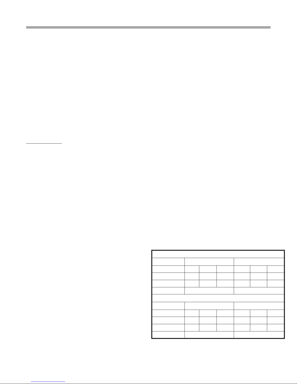
The commissioning table indicates water
temperatures which are suitable for initial unit
commissioning in an environment where the ow rate
and water temperature is not yet stable and to avoid
nuisance shut down of the units freeze and refrigerant
pressure safeties.
The operating table indicates the maximum and
minimum ranges of the unit.
For more specic unit performance reference the
product catalog, the submittal data sheets or contact
your supplier for assistance.
BUILDING COMMISSIONING
Cooling Heating
Unit Size
Source Min/Max
Load Min/Max
Ambient Min/Max
Unit Size
Source Min/Max
Load Min/Max
Ambient Min/Max
036 060/120 170/340 036 060/120 170/340
50/110 50/120 50/90 30/80 30/80 50/70
60/80 60/90 60/90 60/120 60/120 80/120
45/110 39/85
BUILDING OPERATING
COOLING HEATING
036 060/120 170/340 036 060/120 170/340
50/120 50/120 50/110 20/80 20/80 20/70
50/90 50/90 50/90 60/130 60/130 60/120
45/110 39/85
24
Page 25
Wa t e r - t o -W at e r ( 5 0 Y E R ) S e r i e s - P u r o n
R e v. : 1 J u l y, 2 010
Unit & System Checkout
®
BEFORE POWERING SYSTEM, please check the following:
� WARNING! �
Verify ALL water controls are open and allow water ow
prior to engaging the compressor. Freezing of the coax or
water lines can permanently damage the heat pump.
NOTE: The manufacturer strongly recommends
all piping connections, both internal and external
to the unit, be pressure tested by an appropriate
method prior to any nishing of the interior space
or before access to all connections is limited. Test
pressure may not exceed the maximum allowable
pressure for the unit and all components within
the water system. The manufacturer will not be
responsible or liable for damages from water leaks
due to inadequate or lack of a pressurized leak test,
or damages caused by exceeding the maximum
pressure rating during installation.
UNIT CHECKOUT
q Balancing/Shutoff Valves: Ensure all isolation
valves are open, water control valves wired and
open or coax may freeze and burst.
q Line Voltage and Wiring: Ensure Voltage is within
an acceptable range for the unit and wiring and
fuses/breakers are properly sized. Low voltage
wiring is complete.
q Unit Control Transformer: Ensure transformer has
properly selected control voltage tap. 208-230V
units are factory wired for 230 operation unless
specied otherwise.
q
Entering Water: Ensure entering water temperatures
are within operating limits of Table 5.
q Low Water Temperature Cutout: Verify low water
temperature cut-out on CXM is properly set.
q
Water Flow Balancing: Verify inlet and outlet
water temperatures on both Load and source
are recorded for each heat pump upon startup.
This check can eliminate nuisance trip outs and
high velocity water ows that can erode heat
exchangers.
q Unit Controls: Verify CXM settings are proper and
complete.
SYSTEM CHECKOUT
q System Water Temperature: Check load and
source water temperature for proper range and
also verify heating and cooling setpoints for proper
operation.
q System pH: System water pH is 6 - 8.5. Proper
pH promotes longevity of hoses and ttings.
q
System Flushing: Verify all hoses are connected
end to end when ushing to ensure debris
bypasses unit heat exchanger and water valves etc.
Water used in the system must be potable quality
initially and clean of dirt, piping slag, and strong
chemical cleaning agents. Verify all air is purged
from the system. Air in the system can cause poor
operation or system corrosion.
q Cooling Tower/Boiler: Check equipment for
proper setpoints and operation.
q Standby Pumps: Verify the standby pump is
properly installed and in operating condition.
q System Controls: Verify system controls function
and operate in the proper sequence.
q Low Water Temperature Cutout: Verify low water
temperature cut-out controls are provided for the
outdoor portion of the loop or operating problems
will occur.
q System Control Center: Verify control center and
alarm panel for proper setpoints
and operation.
q
Strainers: Verify 20 mesh (841 micron) [0.84mm]
strainers are installed in load and source water
piping. Conrm maintenance schedule for strainers.
q Miscellaneous: Note any questionable aspects of
the installation.
� WARNING! �
To avoid equipment damage, DO NOT leave system
lled in a building without heat during the winter unless
antifreeze is added to system water. Condenser coils
never fully drain by themselves and will freeze unless
winterized with antifreeze.
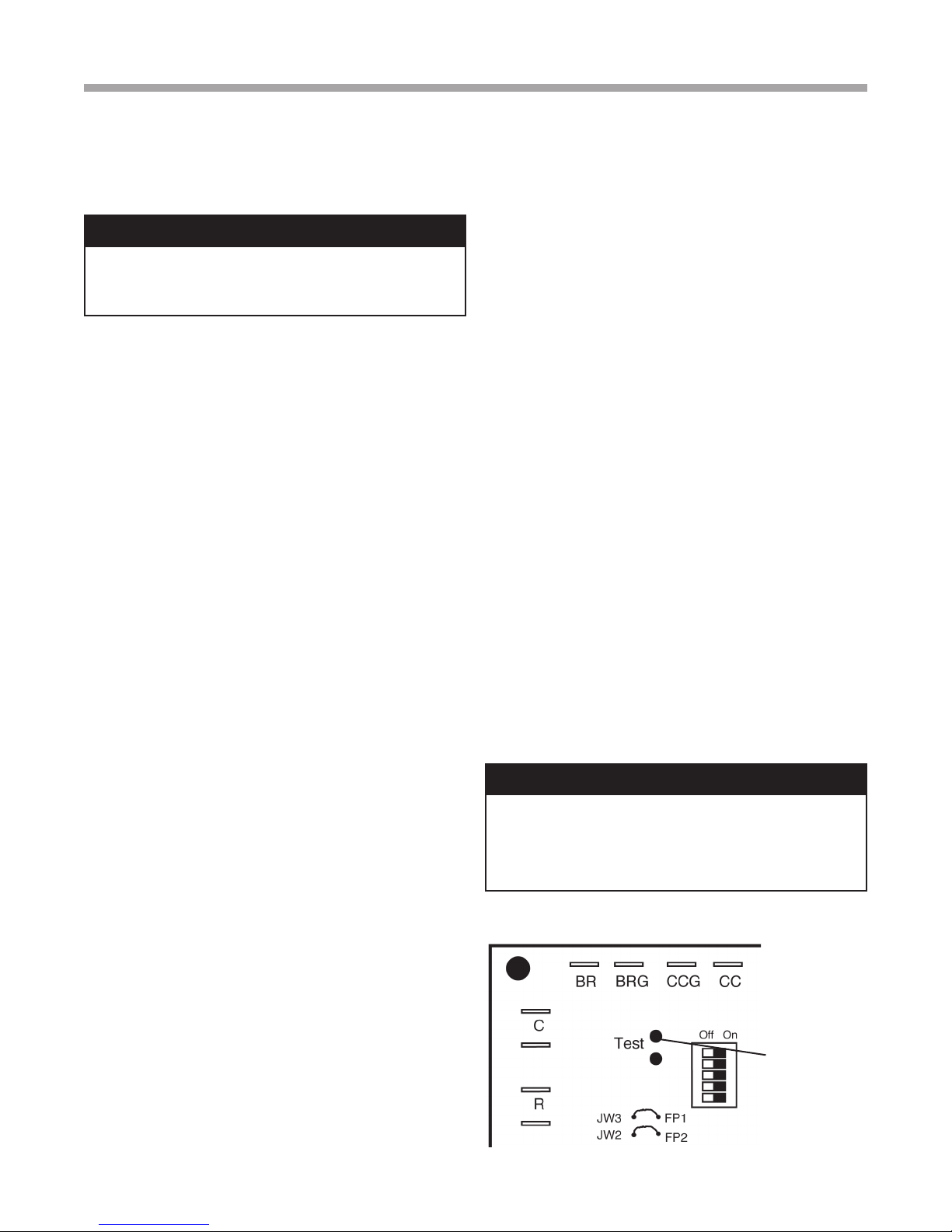
Figure 8: Test Mode Pins
CXM Board
Short test pins
together to enter
Test Mode and
speed-up timing
and delays for
20 minutes.
25
Page 26
Wa t e r - t o -W at e r ( 5 0 Y E R ) S e r i e s - P u r o n
R e v. : 1 J u l y, 2 010
Unit Start Up Procedure
®
� WARNING! �
When the disconnect switch is closed, high voltage is
present in some areas of the electrical panel. Exercise
caution when working with energized equipment.
1. Adjust all valves to their full open position. Turn on
the line power to all heat pump units.
2. Operate each unit in the cooling cycle.
3. Operate each heat pump in the heating
cycle immediately after checking cooling
cycle operation. A time delay will prevent the
compressor from re-starting for approximately ve
(5) minutes.
4. Establish a permanent operating record by logging
the unit operating conditions at initial start-up for
each unit.
5. If a unit fails to operate, conduct the following
checks:
a. Check the voltage and current. They should
comply with the electrical specications
described on the unit nameplate.
b. Look for wiring errors. Check for loose terminal
screws where wire connections have been
made on both the line and low-voltage terminal
boards.
c. Check the supply and return piping. They must
be properly connected to the inlet and outlet
connections on the unit.
d. If the checks described above fail to reveal
the problem and the unit still will not operate,
contact a trained service technician to ensure
proper diagnosis and repair of the equipment.
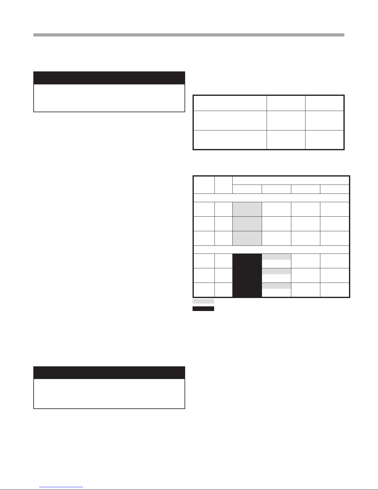
Water Temperature Change Through
Source Heat Exchanger
Water Flow, gpm [l/m]
For Closed Loop: Ground Source
or Closed Loop Systems at 3 gpm
per ton [3.9 l/m per kW]
For Open Loop: Ground Water
Systems at 1.5 gpm per ton
[2.0 l/m per kW]
Rise, Cooling
°F, [°C]
9 - 12
[5 - 6.7]
20 - 26
[11.1 - 14.4]
Drop, Heating
°F, [°C]
4 - 8
[2.2 - 4.4]
10 - 17
[5.6 - 9.4]
Coax Water Pressure Drop 50YER 036-120
Model GPM
30°F 50°F 70°F 90°F
Source/Outdoor Coax
036
060
120
4.5
6.8
9.0
7.5
11.3
15.0
15.0
22.5
30.0
1.7
4.1
7.1
1.5
4.0
6.9
1.7
4.4
7.6
Load/Outdoor Coax
4.5
036
060
120
6.8
9.0
7.5
11.3
15.0
15.0
22.5
30.0
Must use antifreeze if operation falls in grey area
Operation not recommded
Multiply PSI x 2.31 to determine ft of hd
Pressure Drop PSI
1.3
3.4
6.0
1.3
3.4
6.2
1.4
3.8
6.8
0.6
1.4
2.6
1.4
3.5
6.2
1.6
3.8
6.8
1.0
2.8
5.1
1.1
3.0
5.5
1.2
3.3
6.1
0.5
1.3
2.4
1.3
3.2
5.8
1.4
3.5
6.4
0.8
2.4
4.5
0.9
2.7
5.0
0.9
2.7
5.0
0.3
1.1
2.2
1.2
3.0
5.5
1.3
3.3
6.0
Note: Units have a ve minute time delay in the
control circuit that can be eliminated on the CXM
PCB as shown in Figure 8. See controls description
for detailed features of the control.
� WARNING! �
Verify ALL water controls are open and allow water ow
prior to engaging the compressor. Freezing of the coax or
water lines can permanently damage the heat pump.
26
Page 27
Operating Pressures
Source
Entering
Water
Temp °F
50
80
110
Source
Water
Flow
GPM/ton
1.5
2.3
3.0
1.5
2.3
3.0
1.5
2.3
3.0
Load EWT
°F @ 1.5-3.0
GPM/ton
50 99-106 230-234 11-18 18-25
60 111-122 241-243 11-18 18-25 8-17
70 122-137 251-253 17-25 18-25 8-19
80 126-145 254-258 26-35 18-25 9-20
50 98-105 212-214 18-23 14-20
60 106-117 218-220 18-23 14-20 8-17
70 114-129 225-227 24-32 14-20 9-19
80 117-135 228-230 32-41 14-20 9-20
50 87-101 199-203 12-18 12-18
60 91-113 203-207 12-18 12-18 8-17
70 95-124 204-216 16-34 12-18 9-19
80 107-128 212-217 33-35 12-18 9-20
50 104-111 343-348 9-14 18-25
60 121-132 355-360 9-14 18-25 7-16
70 138-152 367-373 9-14 18-25 8-18
80 148-161 377-381 12-23 18-25 9-20
50 103-111 320-325 8-14 14-21
60 118.-129 328-334 8-14 14-21 8-16
70 132-147 336-344 12-20 14-21 8-18
80 140-172 343-353 19-29 14-21 9-20
50 94-110 305-314 9-13 12-18
60 112-121 313-319 9-13 12-18 8-16
70 121-146 317-329 12-20 12-18 9-18
80 131-151 324-333 18-27 12-18 9-20
50 109-116 483-497 9-13 17-23
60 128-135 494-511 9-13 17-23 6-13
70 147-154 505-525 9-13 17-23 7-15
50 109-116 459-473 9-13 15-20
60 127-135 466-484 9-13 15-20 6-13
70 153-159 473-495 9-13 15-20 7-15
50 100-112 444-431 9-14 12-17
60 120-130 449-467 9-14 12-17 6-14
70 131-152 454-474 9-14 12-17 7-15
80 153-164 463-479 13-21 12-17 8-17
Wa t e r - t o -W at e r ( 5 0 Y E R ) S e r i e s - P u r o n
TMW036-120 (TMW120 Per Circuit) (60 Hz I-P Units)
50YER 036-120 (120 Per Circuit)
Cooling
Suction
Pressure
PSIG
Discharge
Pressure
PSIG
Super-heat Sub-cooling
R e v. : 1 J u l y, 2 010
Operating Pressures
Water
Temp
Rise °F
Source
20-28
13-18
9-12
19-28
13-18
8-12
18-26
14-17
8-13
Water
Temp
Drop °F
Load
7-15
7-15
8-16
7-14
7-14
7-15
5-11
5-11
5-12
®
27
Page 28
Wa t e r - t o -W at e r ( 5 0 Y E R ) S e r i e s - P u r o n
R e v. : 1 J u l y, 2 010
Operating Pressures
TMW036-120 (TMW120 Per Circuit) (60 Hz I-P Units)
50YER 036-120 (120 Per Circuit)
Source
Entering
Water
Temp °F
20 3.0
50
80
Source
Water
Flow
GPM/ton
1.5
2.3
3.0
1.5
2.3
3.0
Load EWT
°F @ 1.5-3.0
GPM/ton
60 56-63 199-228 4-14 6-14
80 58-65 286-297 4-14 6-14 5-14
90 59-66 310-344 4-14 6-14 4-14
100 61-65 360-385 4-14 6-14 4-14
120 64-69 459-510 4-14 6-14 4-13
60 85-95 212-224 6-11 7-11
80 91-99 290-310 6-11 7-11 6-17
90 92-101 326-338 6-11 7-11 6-17
100 96-103 381-399 6-11 7-11 5-17
120 100-108 474-488 6-11 7-11 4-16
60 95-102 215-228 6-13 7-11
80 98-106 299-313 6-13 7-11 6-18
90 99-108 329-341 6-13 7-11 6-18
100 102-110 384-401 6-13 7-11 6-17
120 106-114 475-491 6-13 7-11 5-17
60 95-107 215-256 6-14 7-15
80 101-110 310-326 6-14 7-15 7-19
90 103-112 329-376 6-14 7-15 6-19
100 105-114 399-414 6-14 7-15 6-18
120 108-118 476-524 6-14 7-15 5-17
60 109-129 225-237 14-26 5-14
80 123-138 314-327 14-26 5-14 8-19
90 130-142 343-357 10-15 5-14 7-19
100 137-147 402-415 10-15 5-14 7-19
120 150-157 493-504 10-15 5-14 6-20
60 111-132 227-239 14-38 6-15
80 135-147 315-330 14-38 6-15 8-20
90 143-152 344-360 10-16 6-15 8-20
100 145-154 405-418 10-16 6-15 7-20
120 156-163 494-507 10-16 6-15 6-20
60 110-149 227-279 19-44 6-18
80 135-150 286-332 19-44 6-18 8-21
90 145-166 345-408 13-23 6-18 8-21
100 148-158 405-420 13-23 6-18 8-21
Suction
Pressure
PSIG
Discharge
Pressure
PSIG
Heating
Super-heat Sub-cooling
®
Water
Temp
Drop °F
Source
2-6
9-16
6-12
5-9
15-21
10-15
7-12
Water
Temp
Rise °F
Load
5-14
6-17
7-18
7-19
8-18
8-20
9-21
28
Page 29

Wa t e r - t o -W at e r ( 5 0 Y E R ) S e r i e s - P u r o n
R e v. : 1 J u l y, 2 010
Preventative Maintenance
®
Water Coil Maintenance
(Direct ground water applications only) - If the system is
installed in an area with a known high mineral content
(125 P.P.M. or greater) in the water, it is best to establish a
periodic maintenance schedule with the owner so the coil
can be checked regularly. Consult the well water applications
section of this manual for a more detailed water coil material
selection. Should periodic coil cleaning be necessary, use
standard coil cleaning procedures, which are compatible
with the heat exchanger material and copper water lines.
Generally, the more water owing through the unit, the less
chance for scaling. Therefore, 1.5 gpm per ton [2.0 l/m per
kW] is recommended as a minimum ow. Minimum ow
rate for entering water temperatures below 50°F [10°C] is 2.0
gpm per ton [2.6 l/m per kW].
Water Coil Maintenance
(All other water loop applications)
Generally water coil maintenance is not needed for closed
loop systems. However, if the piping is known to have
high dirt or debris content, it is best to establish a periodic
maintenance schedule with the owner so the water coil can
be checked regularly. Dirty installations are typically the result
of deterioration of iron or galvanized piping or components
in the system. Open cooling towers requiring heavy chemical
treatment and mineral buildup through water use can also
contribute to higher maintenance. Should periodic coil
cleaning be necessary, use standard coil cleaning procedures,
which are compatible with both the heat exchanger material
and copper water lines. Generally, the more water owing
through the unit, the less chance for scaling. However, ow
rates over 3 gpm per ton (3.9 l/m per kW) can produce water
(or debris) velocities that can erode the heat exchanger wall
and ultimately produce leaks.
Cabinet
Do not allow water to stay in contact with the cabinet for
long periods of time to prevent corrosion of the cabinet sheet
metal. Generally cabinets are set up from the oor a few
inches for prevention. The cabinet can be cleaned using a
mild detergent.
Refrigerant System
To maintain sealed circuit integrity, do not install service
gauges unless unit operation appears abnormal. Reference
the operating chart for pressure and temperatures. Verify that
air and water ow rates are at proper levels before servicing
the refrigerant circuit.
If the refrigerant circuit is opened for any reason, a new liquid
line lter-drier must be installed.
Hot Water Generator Coils
See water coil maintenance for ground water units. If the
potable water is hard or not chemically softened, the high
temperatures of the desuperheater will tend to scale even
quicker than the water coil and may need more frequent
inspections. In areas with extremely hard water, a HWG is
not recommended.
Compressors
Conduct annual amperage checks to ensure amp draw is
no more than 10% greater than that indicated by serial plate
data.
29
Page 30
:etaD putratS:epyT pooL:remotsuC
Model #:
:% & epyT ezeerfitnA:# laireS
Complaint:
Voltage
Compressor Amps
1 Suction Temp
2 Suction Press
2a Saturation Temp
2b Superheat
3 Discharge Temp
4 Discharge Press
4a Saturation Temp
4b Subcooling
5 Liquid Line Temp
6 Source Water In Tmp
7 Source Water Out Tmp
8 Source Water In Pres
9 Source Water Out Pres
9a
Press Drop
9b Flow Rate GPM [l/s]
10 Load Water In Temp
11 Load Water Out Temp
12 Load Water In Pres
13 Load Water Out Pres
13a
Press Drop
13b Flow Rate GPM [l/s]
Heat of Extraction (Absorption) or Heat of Rejection:
HE or HR =
Flow Rate x Temp. Diff x Fluid Factor
setoNnoitpircseD
<--Water-to-Water units only
<--Water-to-Water units only
<--Water-to-Water units only
<--Water-to-Water units only
Temp Diff. =
<--Water-to-Water units only
Temp Diff. =
Heating Cooling
Refrigeration Troubleshooting Form
Water-to-Water Units
COMPRESSOR
DISCHARGE
SUCTION
HWG**
EXPANSION
VALVE
FILTE R
DRIER
REVERSING
VALVE
HEATING POSITION COOLING POSITION
1
COAX
COAX
5
1210
1311
9
7
8
6
4
3
2
FP2:
HEATING
LIQUID
LINE
5
FP1:
COOLING
LIQUID
LINE
CONDENSER (HT G)
EVAP ORATOR (CL G)
CONDENSER (COOLING)
EV APORATOR (HEATING)
**Turn off HW G before
t roubleshooting.
REFRIG FLOW - HEATING REFRIG FLOW - COOLING
REFRIGERANT: HFC-410A
OPERATING MODE: HEATING COOLING
Fluid Factor: (for Btuh)
500 (Water); 485 (Antifreeze)
Source
Load
Fluid Factor: (for kW)
4.18 (Water); 4.05 (Antifreeze)
Wa t e r - t o -W at e r ( 5 0 Y E R ) S e r i e s - P u r o n
R e v. : 1 J u l y, 2 010
Refrigeration Troubleshooting Form
®
30
Page 31
performance, write or call:
NOTE: Some states or Canadian provinces do not allow limitations on how long an implied warranty lasts, or the limitation or exclusions of consequential or incidental damages, so the foregoing exclusions and limitations may not apply to you. This warranty gives you specic
legal rights, and you may also have other rights which vary from state to state and from Canadian province to Canadian province.
Please refer to the Carrier Installation, Operation and Maintenance Manual for operating and maintenance instructions. Rev.: 6/10
ordered from Carrier prior to July 1, 2010 (this would generally include Carrier Geothermal Units with serial numbers beginning with “2610V” and earlier). If you are unsure if this Limited Express Warranty applies to the product you have purchased, contact Carrier at the phone
number or address below.
Limitation: This Limited Express Warranty is given in lieu of all other warranties. If, notwithstanding the disclaimers contained herein, it is determined that other warranties exist, any such express warranty, including without limitation any express warranties or any implied
warranties of tness for particular purpose and merchantability, shall be limited to the duration of the Limited Express Warranty.
LIMITATION OF REMEDIES
In the event of a breach of the Limited Express Warranty, Carrier will only be obligated at Carrier ’s option to repair the failed part or unit, or to furnish a new or rebuilt part or unit in exchange for the part or unit which has failed. If after written notice to Carrier ’s factory in
Oklahoma City, Oklahoma of each defect, malfunction or other failure, and a reasonable number of attempts by Carrier to correct the defect, malfunction or other failure, and the remedy fails of its essential purpose, Carrier shall refund the purchase price paid to Carrier in
exchange for the return of the sold good(s). Said refund shall be the maximum liability of Carrier. THIS REMEDY IS THE SOLE AND EXCLUSIVE REMEDY OF THE BUYER OR PURCHASER AGAINST CARRIER FOR BREACH OF CONTRACT, FOR THE
BREACH OF ANY WARRANTY OR FOR CARRIER’S NEGLIGENCE OR IN STRICT LIABILITY.
LIMITATION OF LIABILITY
Carrier shall have no liability for any damages if Carrier’s performance is delayed for any reason or is prevented to any extent by any event such as, but not limited to: any war, civil unrest, government restrictions or restraints, strikes, or work stoppages, re, ood, accident,
shortages of transportation, fuel, material, or labor, acts of God or any other reason beyond the sole control of Carrier. CARRIER EXPRESSLY DISCLAIMS AND EXCLUDES ANY LIABILITY FOR CONSEQUENTIAL OR INCIDENTAL DAMAGE IN CONTRACT, FOR
BREACH OF ANY EXPRESS OR IMPLIED WARRANTY, OR IN TORT, WHETHER FOR CARRIER’S NEGLIGENCE OR AS STRICT LIABILITY.
OBTAINING WARRANTY PERFORMANCE
Normally, the dealer or service organization who installed the products will provide warranty performance for the owner. Should the installer be unavailable, contact any Carrier recognized distributor, dealer or service organization. If assistance is required in obtaining warranty
Wa t e r - t o -W at e r ( 5 0 Y E R ) S e r i e s - P u r o n
R e v. : 1 J u l y, 2 010
Warranty
It is expressly understood that unless a statement is specically identied as a warranty, statements made by Carrier Corporation, a Delaware corporation, (“Carrier”) or its representatives, relating to Carrier’s products, whether oral, written or contained in any sales literature,
catalog or agreement, are not express warranties and do not form a part of the basis of the bargain, but are merely Carrier’s opinion or commendation of Carrier’s products. EXCEPT AS SPECIFICALLY SET FORTH HEREIN, THERE IS NO EXPRESS WARRANTY
AS TO ANY OF CARRIER’S PRODUCTS. CARRIER MAKES NO WARRANTY AGAINST LATENT DEFECTS. CARRIER MAKES NO WARRANTY OF MERCHANTABILITY OF THE GOODS OR OF THE FITNESS OF THE GOODS FOR ANY
PARTICULAR PURPOSE.
GRANT OF LIMITED EXPRESS WARRANTY
Carrier warrants its residential geothermal products, purchased and retained in the United States of America and Canada, to be free from defects in material and workmanship under normal use and maintenance as follows: (1) Residential geothermal air conditioning, heating and/
or heat pumps with model numbers beginning with 50Y that are built or sold by Carrier (“Carrier Geothermal Units”) for ten (10) years from the Warranty Inception Date (as dened below); (2) Auxiliary electric heaters and geothermal pumping modules built or sold by Carrier,
when installed with Carrier Geothermal Units, for ten (10) years from the Warranty Inception Date (as dened below); (3) Sealed refrigerant circuit components of Carrier Geothermal Units (which components only include the compressor, refrigerant to air/water heat exchangers,
reversing valve body and refrigerant metering device) for ten (10) years from the Warranty Inception Date (as dened below); and (4) Other accessories and parts built or sold by Carrier, when installed with Carrier Geothermal Units, for one (1) year from the date of shipment
from Carrier. The “Warranty Inception Date” shall be the date of original unit installation, or six (6) months from date of unit shipment from Carrier, whichever comes rst.
To make a claim under this warranty, parts must be returned to Carrier in Oklahoma City, Oklahoma, freight prepaid, no later than ninety (90) days after the date of the failure of the part; if Carrier determines the part to be defective and within Carrier’s Limited Express Warranty,
Carrier shall, when such part has been either replaced or repaired, return such to a factory recognized distributor, dealer or service organization, F.O.B. Carrier, Oklahoma City, Oklahoma, freight prepaid. The warranty on any part repaired or replaced under warranty expires at the
end of the original warranty period.
This Limited Express Warranty shall cover the labor incurred by Carrier authorized service personnel in connection with the installation of a new or repaired warranty part that is covered by this Limited Express Warranty only to the extent specically set forth in the then existing
labor allowance schedule provided by Carrier’s Warranty Department and only as follows: (1) Carrier Geothermal Units for two (2) years from the Warranty Inception Date; (2) Auxiliary electric heaters and geothermal pumping modules built or sold by Carrier, when installed
with Carrier Geothermal Units, for two (2) years from the Warranty Inception Date; and (3) Sealed refrigerant circuit components of Carrier Geothermal Units (which components only include the compressor, refrigerant to air/water heat exchangers, reversing valve body and
refrigerant metering device) for ve (5) years from the Warranty Inception Date. Actual Labor costs are not covered by this Limited Express Warranty to the extent they exceed the amount allowed under said allowance schedule, they are not specically provided for in said
allowance schedule, they are not the result of work performed by Carrier authorized service personnel, they are incurred in connection with a part not covered by this Limited Express Warranty, or they are incurred more than the time periods set forth in this paragraph after the
Warranty Inception Date.
This warranty does not cover and does not apply to: (1) Air lters, fuses, refrigerant, uids, oil; (2) Products relocated after initial installation; (3) Any portion or component of any system that is not supplied by Carrier, regardless of the cause of the failure of such portion
or component; (4) Products on which the unit identication tags or labels have been removed or defaced; (5) Products on which payment to Carrier, or to the owner’s seller or installing contractor, is in default; (6) Products subjected to improper or inadequate installation,
maintenance, repair, wiring or voltage conditions; (7) Products subjected to accident, misuse, negligence, abuse, re, ood, lightning, unauthorized alteration, misapplication, contaminated or corrosive air or liquid supply, operation at abnormal air or liquid temperatures or ow
rates, or opening of the refrigerant circuit by unqualied personnel; (8) Mold, fungus or bacteria damages; (9) Corrosion or abrasion of the product; (10) Products supplied by others; (11) Products which have been operated in a manner contrary to Carrier’s printed instructions;
(12) Products which have insufcient performance as a result of improper system design or improper application, installation, or use of Carrier’s products; or (13) Electricity or fuel costs, or any increases or unrealized savings in same, for any reason whatsoever.
This Limited Express Warranty provides the limited labor allowance coverage set forth above. Otherwise, Carrier is not responsible for: (1) The costs of any uids, refrigerant or system components supplied by others, or associated labor to repair or replace the same, which is
incurred as a result of a defective part covered by Carrier’s Limited Express Warranty; (2) The costs of labor, refrigerant, materials or service incurred in diagnosis and removal of the defective part, or in obtaining and replacing the new or repaired part; (3) Transportation costs of
the defective part from the installation site to Carrier, or of the return of that part if not covered by Carrier’s Limited Express Warranty; or (4) The costs of normal maintenance.
This Limited Express Warranty applies to Carrier residential geothermal products ordered from Carrier on or after July 1, 2010 (This would generally include Carrier Geothermal Units with serial numbers beginning with “2710V” and later), and is not retroactive to any products
®�
CARRIER CORPORATION
LIMITED EXPRESS WARRANTY/LIMITATION OF REMEDIES AND LIABILITY FOR RESIDENTIAL
GEOTHERMAL PRODUCTS WITH LABOR ALLOWANCE
®
Customer Service • 7300 SW 44th Street • Oklahoma City, Oklahoma 73179 • (405) 745-2920
Part No.: CA234
31
Page 32

Wa t e r - t o -W at e r ( 5 0 Y E R ) S e r i e s - P u r o n
R e v. : 1 J u l y, 2 010
Notes
®
32
Page 33

Wa t e r - t o -W at e r ( 5 0 Y E R ) S e r i e s - P u r o n
R e v. : 1 J u l y, 2 010
Notes
®
33
Page 34
Wa t e r - t o -W at e r ( 5 0 Y E R ) S e r i e s - P u r o n
R e v. : 1 J u l y, 2 010
®
Revision History
Date Page # Description
1 July, 10 Various Warranty, Nomenclature, Unit Photos Updated
20 May, 10
01 May, 10 15 HWG Piping Drawings Revised
30 Oct., 09 23 ‘Safety Features - CXM/DXM Controls’ Section Updated
15 Sept., 09 23 ‘Safety Features - CXM/DXM Controls’ Section Updated
24 June, 09 3 Decoder Example Updated
03 June, 09 31 Updated Refrigeration Troubleshooting Form
03 June, 09 15 Updated HWG Illustrations
02 June, 09 5 Updated Cautions in the General Information Section
01 June, 09 27 Updated Operating Pressure Heating Table
07 May, 09 24 Unit Commissioning and Operating Conditions Updated
29 April, 09 All First Published
6 50YER060 & 50YER120 Physical Data Table Updated
27 & 28 Operating Pressures Table Updated
ISO 9001:2000
Certified
Quality: First & Always
*97B0069N01*
97B0069N01
The Manufacturer works continually to improve its products. As a result, the design and specications of each product at the time for order may
be changed without notice and may not be as described herein. Please contact the Manufacturer’s Customer Service Department at 1-405745-6000 for specic information on the current design and specications. Statements and other information contained herein are not express
warranties and do not form the basis of any bargain between the parties, but are merely Manufacturer’s opinion or commendation of its products.
The management system governing the manufacture of Manufacturer’s products is ISO 9001:2000 certied.
© LSB, Inc. 2009
34
7300 S.W. 44th Street
Oklahoma City, OK 73179
Phone: 405-745-6000
Fax: 405-745-6058
Rev.: 1 July, 2010
 Loading...