

Carrier 50XZ024, 50XZ036, 50XZ042, 50XZ048, 50XZ060 Installation, Start-up And Service Instructions Manual
...Page 1
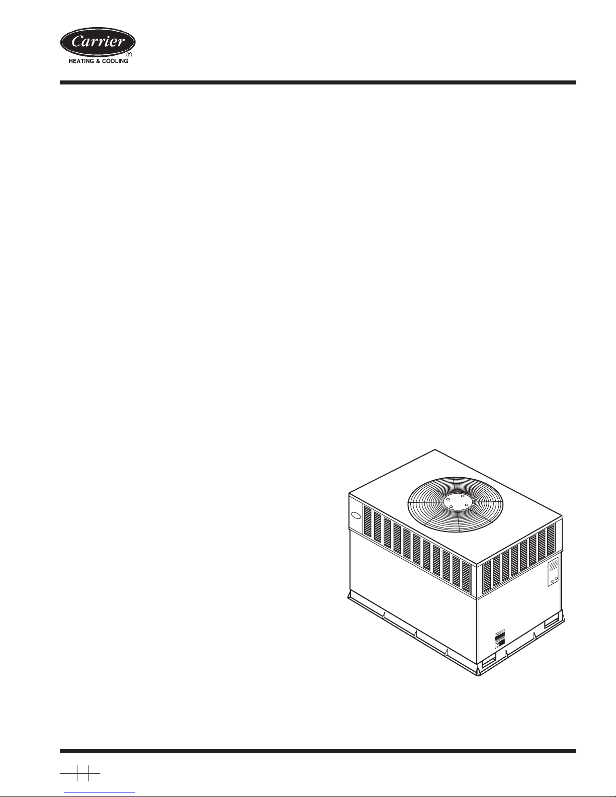
50XZ 024–060
Single-Packaged Heat Pump Units
with Puron® (R-410A) Refrigerant
Installation, Start-Up,
and Service Instructions
NOTE: Read the entire instruction manual before starting the
installation.
This symbol → indicates a change since the last issue.
TABLE OF CONTENTS
SAFETY CONSIDERATIONS.....................................................2
Introduction ....................................................................................2
Receiving and Installation..............................................................2
Check Equipment......................................................................2
IDENTIFY UNIT................................................................2
INSPECT SHIPMENT........................................................2
Provide Unit Support................................................................2
ROOF CURB.......................................................................2
SLAB MOUNT ...................................................................2
GROUND MOUNT ............................................................2
Provide Clearances....................................................................2
Rig and Place Unit....................................................................3
INSPECTION......................................................................3
INSTALLATION ................................................................4
Select and Install Ductwork .....................................................5
CONVERTING HORIZONTAL DISCHARGE UNITS TO
DOWNFLOW (VERTICAL) DISCHARGE UNITS.........7
Provide for Condensate Disposal.............................................7
Install Electrical Connections...................................................8
HIGH-VOLTAGE CONNECTIONS..................................8
ROUTING POWER LEADS INTO UNIT........................9
CONNECTING GROUND LEAD TO GROUND LUG ..9
ROUTING CONTROL POWER WIRES (24-V)..............9
Easy Select™—50XZ .........................................................9
50XZ Sequence Of Operation...........................................17
SPECIAL PROCEDURES FOR 208-V OPERATION ...17
PRE-START-UP ..........................................................................18
START-UP...................................................................................18
50XZ: Start-Up .......................................................................18
Check for Refrigerant Leaks..................................................19
Start-Up Adjustments..............................................................19
CHECKING COOLING AND HEATING CONTROL OP-
ERATION..........................................................................19
CHECKING AND ADJUSTING REFRIGERANT
CHARGE...........................................................................19
REFRIGERANT CHARGE..............................................20
NO CHARGE....................................................................20
LOW CHARGE COOLING .............................................20
TO USE COOLING CHARGING CHARTS ..................20
INDOOR AIRFLOW AND AIRFLOW ADJUST-
MENTS..............................................................................20
Defrost Control .......................................................................20
Quiet Shift..........................................................................20
Defrost................................................................................20
MAINTENANCE.........................................................................22
Air Filter..................................................................................23
Indoor Blower and Motor.......................................................23
Outdoor Coil, Indoor Coil, and Condensate Drain Pan........23
Outdoor Fan............................................................................24
Electrical Controls and Wiring...............................................24
Refrigerant Circuit..................................................................24
Indoor Airflow........................................................................24
Metering Devices–TXV & Accurater Piston.........................24
Pressure Switches....................................................................25
Loss of Charge Switch ...........................................................25
High-Pressure Switch..............................................................25
Copeland Scroll Compressor (Puron Refrigerant).................26
Refrigerant System..................................................................26
Refrigerant .........................................................................26
Compressor Oil..................................................................26
Servicing Systems on Roofs with Synthetic Materials....26
Liquid Line Filter Drier ....................................................26
Puron (R-410A) Refrigerant Charging .............................26
System Information.................................................................26
Loss of Charge Switch......................................................26
Check Defrost Thermostat ................................................26
TROUBLESHOOTING ...............................................................27
Start-Up Checklist........................................................................27
NOTE TO INSTALLER — READ THESE INSTRUCTIONS
CAREFULLY AND COMPLETELY before installing this unit.
Also, make sure the Owner’s Manual and Service Instructions are
left with the unit after installation.
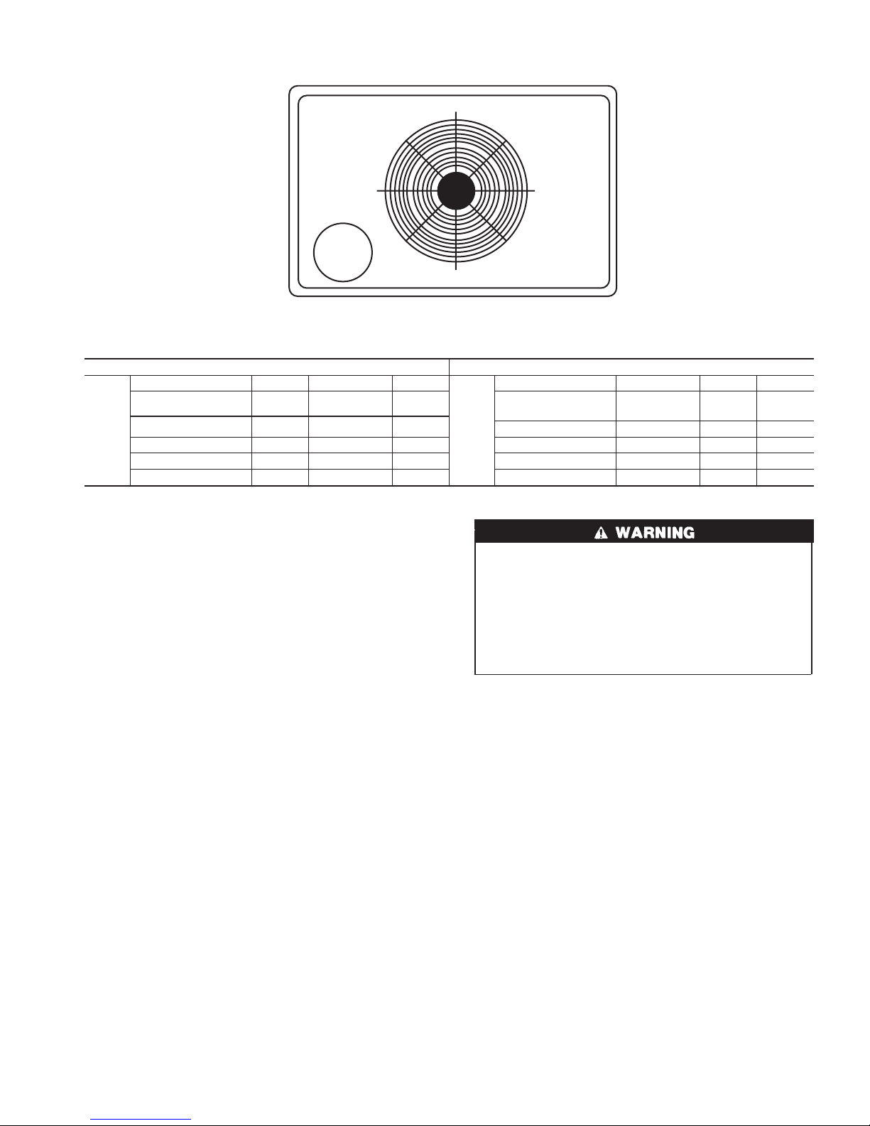
Fig. 1—Unit 50XZ
C99064
Visit www.carrier.com
Manufacturer reserves the right to discontinue, or change at any time, specifications or designs without notice and without incurring obligations.
Book 1 4
Tab 5a 5a
PC101CatalogNo.535–00114 PrintedinU.S.A.Form50XZ-2SIPg18–03Replaces:50XZ-1SI
Page 2
SAFETY CONSIDERATIONS
Installation and servicing of air-conditioning equipment can be
hazardous due to system pressure and electrical components. Only
trained and qualified personnel should install, repair, or service
air-conditioning equipment.
Untrained personnel can perform basic maintenance functions of
cleaning coils and filters. All other operations should be performed
by trained service personnel. When working on air-conditioning
equipment, observe precautions in the literature, tags, and labels
attached to the unit, and other safety precautions that may apply.
Follow all safety codes. Wear safety glasses and work gloves. Use
quenching cloth for unbrazing operations. Have fire extinguisher
available for all brazing operations.
Improper installation, adjustment, alteration, service, maintenance, or use can cause explosion, fire, electric shock, or
other occurrences, which could cause serious injury or death
or damage your property. Consult a qualified installer or
service agency for information or assistance. The qualified
installer or agency must use only factory-authorized kits or
accessories when modifying this product.
Recognize safety information. This is the safety-alert symbol .
When you see this symbol on the product or in instructions or
manuals, be alert to the potential for personal injury.
Understand the signal words — DANGER, WARNING, CAUTION, and NOTE. Danger identifies the most serious hazards,
which will result in severe personal injury or death. Warning
indicates a condition that could cause serious personal injury or
death. Caution is used to identify unsafe practices, which would
result in minor personal injury or product and property damage.
NOTE is used to highlight suggestions which will result in
enhanced installation, reliability, or operation.
1. The power supply (volts, phase, and hertz) must correspond to
that specified on unit rating plate.
2. The electrical supply provided by the utility must be sufficient
to handle load imposed by this unit.
3. This installation must conform with local building codes and
with NEC (National Electrical Code). Refer to provincial and
local plumbing or waste water codes and other applicable local
codes.
Before performing service or maintenance operations on
system, turn off main power to unit. Turn off accessory heater
power switch if applicable. Electrical shock could cause
severe injury or death.
Puron (R-410A) systems operate at higher pressures than
standard R-22 systems. DO not use R-22 service equipment
or components on Puron (R-410A) equipment. Ensure service
equipment is rated for Puron (R-410A)
INTRODUCTION
The 50XZ heat pump is fully self-contained and designed for
outdoor installation. (See Fig. 1) Standard units are shipped in a
horizontal-discharge configuration for installation on a groundlevel slab. Standard units can be converted to downflow (vertical)
discharge configurations for rooftop applications.
RECEIVING AND INSTALLATION
Step 1—Check Equipment
IDENTIFY UNIT
The unit model number and serial number are stamped on the unit
identification plate. Check this information against shipping papers.
INSPECT SHIPMENT
Inspect for shipping damage while unit is still on shipping pallet.
If unit appears to be damaged or is torn loose from its anchorage,
have it examined by transportation inspectors before removal.
Forward claim papers directly to transportation company. Manufacturer is not responsible for any damage incurred in transit.
Check all items against shipping list. Immediately notify the
nearest Carrier Air Conditioning office if any item is missing. To
prevent loss or damage, leave all parts in original packages until
installation.
Step 2—Provide Unit Support
ROOF CURB
Install accessory roof curb in accordance with instructions shipped
with curb (See Fig. 5). Install insulation, cant strips, roofing, and
flashing. Ductwork must be attached to curb.
IMPORTANT: The gasketing of the unit to the roof curb is critical
for a watertight seal. Install gasketing material supplied with the
roof curb. Improperly applied gasketing also can result in air leaks
and poor unit performance.
Curb should be level to within 1/4 in. (See Fig. 6). This is
necessary for unit drain to function properly. Refer to accessory
roof curb installation instructions for additional information as
required.
SLAB MOUNT
Place the unit on a solid, level concrete pad that is a minimum of
4 in. thick with 2 in. above grade (See Fig. 7). The slab should
extend approximately 2 in. beyond the casing on all 4 sides of the
unit. Do not secure the unit to the slab except when required by
local codes.
GROUND MOUNT
The unit may be installed either on a slab or placed directly on the
ground if local codes permit. Place the unit on level ground
prepared with gravel for condensate discharge.
Step 3—Provide Clearances
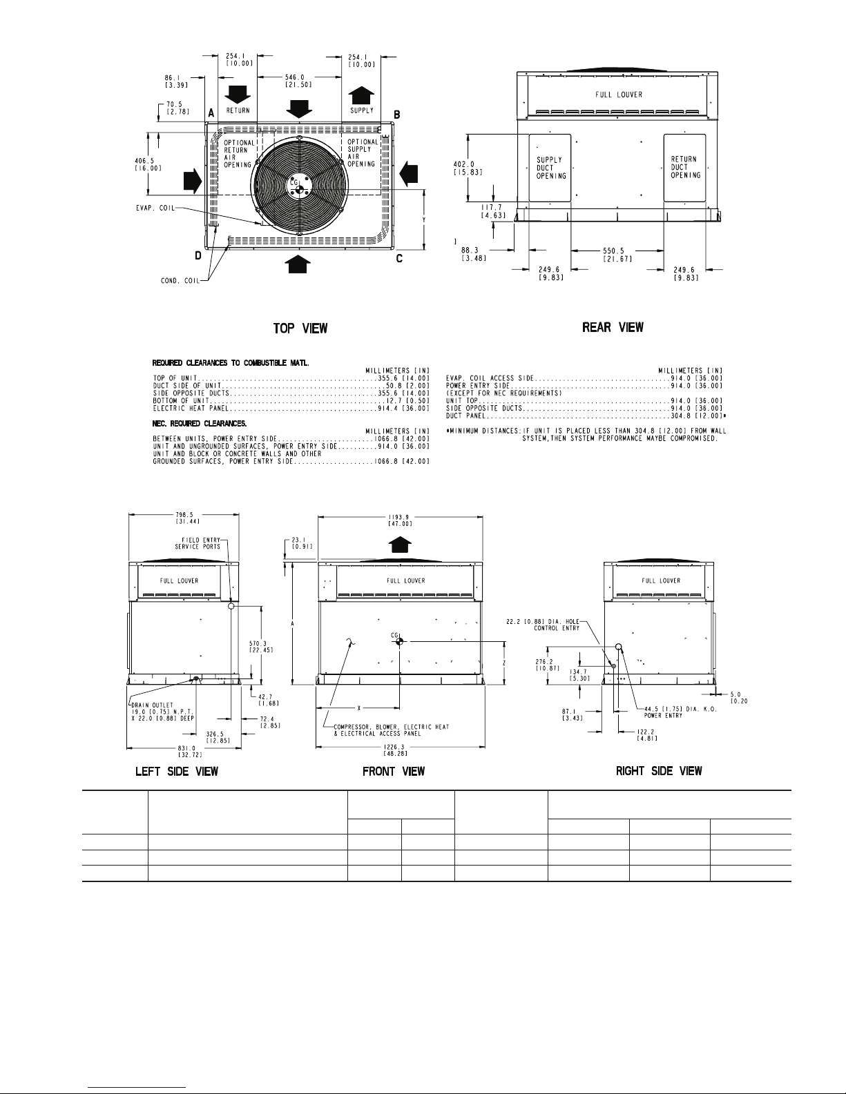
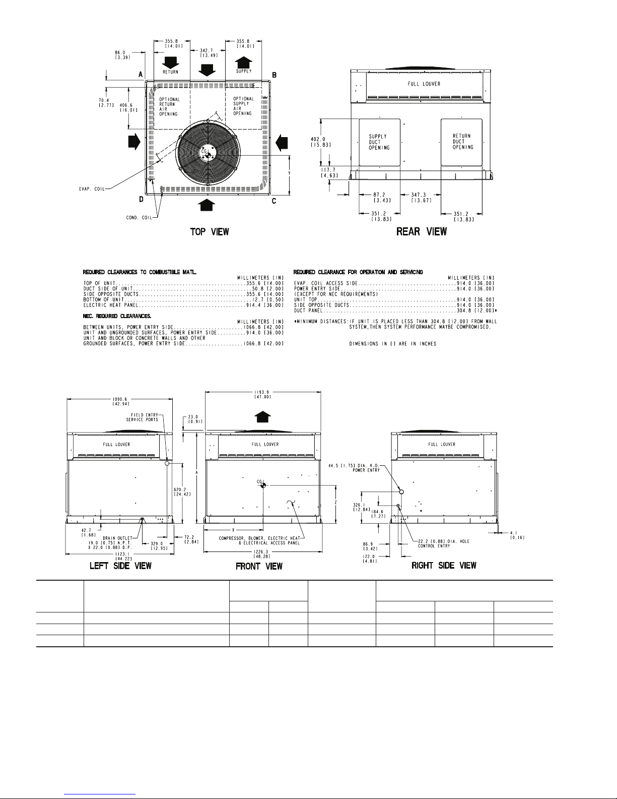
The required minimum service clearances are shown in Figs. 2 and
3. Adequate ventilation and outdoor air must be provided. The
outdoor fan draws air through the outdoor coil and discharges it
through the top fan grill. Be sure that the fan discharge does not
recirculate to the outdoor coil. Do not locate the unit in either a
corner or under an overhead obstruction. The minimum clearance
under a partial overhang (such as a normal house overhang) is 48
in. above the unit top. The maximum horizontal extension of a
partial overhang must not exceed 48 in.
IMPORTANT: Do not restrict outdoor airflow. An air restriction
at either the outdoor-air inlet or the fan discharge may be
detrimental to compressor life.
Do not place the unit where water, ice, or snow from an overhang
or roof will damage or flood the unit. Do not install the unit on
carpeting or other combustible materials. Slab-mounted units
should be at least 4 in. above the highest expected water and runoff
levels. Do not use unit if it has been under water.
2
Page 3
Step 4—Rig and Place Unit
Rigging and handling of this equipment can be hazardous for many
reasons due to the installation location (roofs, elevated structures,
etc.)
Only trained, qualified crane operators and ground support staff
should handle and install this equipment.
When working with this equipment, observe precautions in the
literature, on tags, stickers, and labels attached to the equipment,
and any other safety precautions that might apply.
Follow all applicable safety codes. Wear safety shoes and work
gloves.
INSPECTION
Prior to initial use, and at monthly intervals, all rigging brackets
and straps should be visually inspected for any damage, evidence
of wear, structural deformation, or cracks. Particular attention
should be paid to excessive wear at hoist hooking points and load
support areas. Brackets or straps showing any kind of wear in these
areas must not be used and should be discarded.
Fig. 2—50XZ024-036 Unit Dimensions
UNIT ELECTRICAL CHARACTERISTICS
UNIT WEIGHT
UNIT HEIGHT
IN. (MM)
”A”
CENTER OF GRAVITY
IN. (MM)
lb kg X Y Z
50XZ024 208/230-1-60 350 159 39.02 (991.1) 20.0 (508.0) 19.3 (489.0) 17.6 (447.0)
50XZ030 Not Available At This Time ” ” ” ” ” ”
50XZ036 208/230-1-60,208/230-3-60 373 169 41.02 (1041.9) 20.0 (508.0) 14.0 (355.6) 13.0 (330.2)
C00160
Required Clearance for Operation and Service
3
Page 4
INSTALLATION
1. Remove unit from shipping carton. Leave top shipping skid on
the unit as a spreader bar to prevent the rigging straps from
damaging the unit. If the wood skid is not available, use a
spreader bar of sufficient length to protect unit from damage.
2. Position the lifting bracket assembly around the base of the
unit. Be sure the strap does not twist.
3. Place each of the 4 metal lifting brackets into the rigging holds
in the composite unit base.
4. Thread lifting bracket strapping around bottom perimeter of
unit as follows:
a. Open lever of tension buckle (ratchet type).
b. Feed strapping through tension buckle as shown in Fig. 8.
c. Pull strapping through tension buckle unit taut.
Fig. 3—50XZ 042-060 Unit Dimensions
UNIT ELECTRICAL CHARACTERISTICS
UNIT WEIGHT
UNIT HEIGHT
IN. (MM)
”A”
CENTER OF GRAVITY
IN. (MM)
lb kg X Y Z
50XZ042 Not Available At This Time ” ” ” ” ” ”
50XZ048 208/230-1-60, 208/230-3-60 463 210 44.98 (1142.5) 19.5 (495.3) 17.6 (447.6) 18.0 (457.2)
50XZ060 208/230-1-60, 208/230-3-60 499 226 46.98 (1193.3) 21.0 (533.4) 20.0 (508.0) 17.6 (442.0)
C00161
4
Page 5
d. Snap lever down to lock strap in tension buckle. To release
strapping, squeeze safety latch, lift lever, and pull webbing
outward.
5. Tighten the tension buckle until it is taut. Lifting brackets
must be secure in the rigging holds.
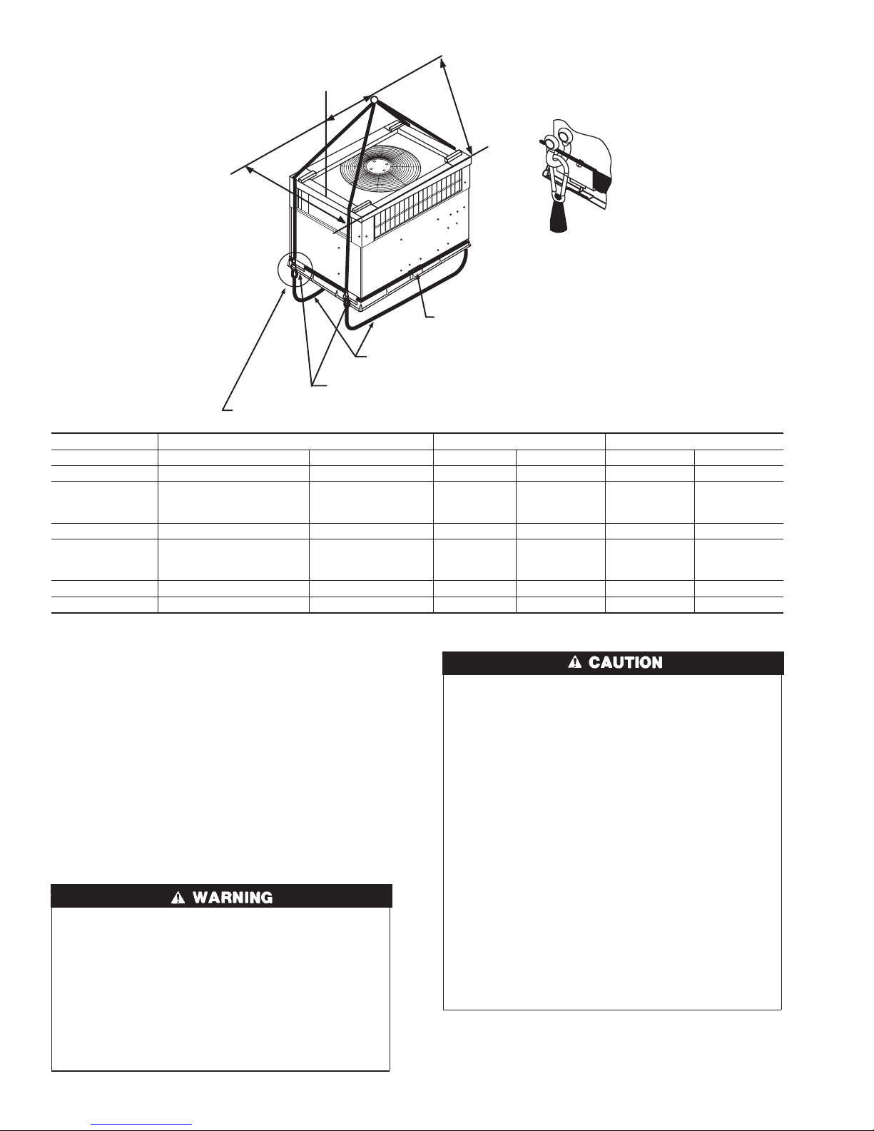
6. Attach field-supplied clevis or hook of sufficient strength to
hole in the lifting bracket. (See Fig. 9)
7. Attach the 2 safety straps directly to the clevis or hook at the
4 rigging brackets. DO NOT attach the safety straps to the
lifting brackets. (See Fig. 9)
8. Position lifting point directly over the unit’s center of gravity.
9. Lift unit. When unit is directly over the roof curb, remove the
2 safety straps. Lower the equipment onto the roof curb.
10. After the unit is placed on the roof curb or mounting pad,
remove the top crating. On 50XZ060 units only, 2 wire ties
fastened to the outdoor coils and reversing valve/accumulator
assembly must be cut. Remove the left and front louver panels
and corner post to access wire ties. The wire tie to be cut on
the left is located approximately 4 in. down the tube sheet. The
wire tie to be cut on the right is located approximately 6 in.
down the tube sheet.
Step 5—Select and Install Ductwork
The design and installation of the duct system must be in
accordance with the standards of the NFPA for installation of
non-residence type air conditioning and ventilating systems, NFPA
90A or residence-type, NFPA 90B and/or local codes and ordinances.
Select and size ductwork, supply-air registers, and return air grilles
according to ASHRAE (American Society of Heating, Refrigeration, and Air Conditioning Engineers) recommendations.
The unit has duct flanges on the supply- and return-air openings on
the side of the unit.
When designing and installing ductwork, consider the following:
For vertical supply and return units, tools or parts could drop
into ductwork and cause serious injury or death. Install a 90
degree turn in the return ductwork between the unit and the
conditioned space. If a 90 degree elbow cannot be installed,
then a grille of sufficient strength and density should be
installed to prevent objects from falling into the conditioned
space. Units with electric heaters require 90 degree elbow in
supply duct.
1. All units should have field-supplied filters or accessory filter
rack installed in the return-air side of the unit. Recommended
sizes for filters are shown in Table 1.
2. Avoid abrupt duct size increases and reductions. Abrupt
change in duct size adversely affects air performance.
IMPORTANT: Use flexible connectors between ductwork and
unit to prevent transmission of vibration. Use suitable gaskets to
ensure weather tight and airtight seal. When electric heat is
installed, use fireproof canvas (or similar heat resistant material)
connector between ductwork and unit discharge connection. If
flexible duct is used, insert a sheet metal sleeve inside duct. Heat
resistant duct connector (or sheet metal sleeve) must extend 24-in.
from electric heater element.
3. Size ductwork for cooling air quantity (cfm). The minimum
air quantity for proper electric heater operation is listed in
Table 2. Heater limit switches may trip at air quantities below
those recommended.
4. Seal, insulate, and weatherproof all external ductwork. Seal,
insulate and cover with a vapor barrier all ductwork passing
through conditioned spaces. Follow latest Sheet Metal and Air
Conditioning Contractors National Association (SMACNA)
and Air Conditioning Contractors Association (ACCA) minimum installation standards for residential heating and air
conditioning systems.
Fig. 4—Corner Weights
CORNER WEIGHTS (SMALL CABINET) CORNER WEIGHTS (LARGE CABINET)
Model 50XZ
Unit 24 30 36
Model 50XZ
Unit 42 48 60
Total Weight 350
Not
Available
373 Total Weight
Not
Available
463 499
Corner Weight 1 70 “ 75 Corner Weight 1 “ 98 107
Corner Weight 2 54 “ 58 Corner Weight 2 “ 61 70
Corner Weight 3 84 “ 90 Corner Weight 3 “ 127 136
Corner Weight 4 141 “ 150 Corner Weight 4 “ 177 186
C00071
12
43
x
y
5
Page 6
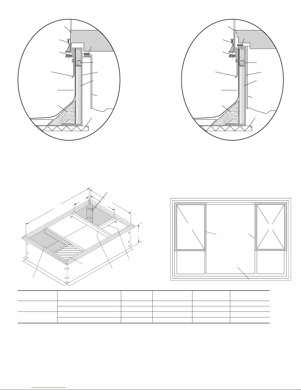
Fig. 5—Roof Curb Dimensions
UNIT SIZE ODS CATALOG NUMBER
A
IN. (MM)
B
IN. (MM)
C
IN. (MM)
D
IN. (MM)
50XZ024-036
CPRFCURB006A00 8 (203) 11(279) 161/2 (419) 28-3/4 (730)
CPRFCURB007A00 14 (356) 11(279) 161/2 (419) 28-3/4 (730)
50XZ042-060
CPRFCURB008A00 8 (203) 16 3/16 (411) 17 3/8 (441) 40-1/4 (1022)
CPRFCURB009A00 14 (356) 16 3/16 (411) 17 3/8 (441) 40-1/4 (1022)
NOTES:
1. Roof curb must be set up for unit being installed.
2. Seal strip must be applied, as required, to unit being installed.
3. Dimensions in ( ) are in millimeters.
4. Roof curb is made of 16-gage steel.
5. Table lists only the dimensions, per part number, that have changed.
6. Attach ductwork to curb (flanges of duct rest on curb).
7. Insulated panels: 1-in. thick fiberglass 1 lb. density.
8. Dimensions are in inches.
9. When unit mounting screw is used (see Note A), a retainer bracket must be used as well. This bracket must also be used when required by code for hurricaneor
seismic conditions. This bracket is available through Micrometl.
C00076
Gask et around
outer edge
Insulated
deck pan
Gask et around
duct
S/A
R/A
HVAC unit
base
*Gask eting
outer flange
Flashing field
supplied
Roofing material
field supplied
Cant str ip
field supplied
*Provided with roofcurb
Roof
Duct wo rk
field supplied
Insulation (field
supplied)
Roofcurb*
Wood nailer*
Gask eting
inner flange*
Scre w
(NO TE A)
Roof Curb for Small Cabinet
Note A: When unit mounting scre w is used,
retainer bra cke t must also be used.
HVAC unit
base
*Gask eting
outer flange
Flashing field
supplied
Roofing material
field supplied
Cant str ip
field supplied
*Provided with roofcurb
Roof
Duct wo rk
field supplied
Insulation (field
supplied)
Roofcurb*
Wood nailer*
Gask eting
inner flange*
Scre w
(NOTE A)
Roof Curb for Large Cabinet
Note A: When unit mounting scre w is used,
retainer bra cket must also be used.
A
B Ty p.
Supply opening
(B x C)
Long
Support
D
44
5
/16"
Return opening
(B X C)
Insulated
deck pan
Short
Support
C Typ.
6
Page 7
5. Secure all ducts to building structure. Flash, weatherproof, and
vibration-isolate duct openings in wall or roof according to
good construction practices.
CONVERTING HORIZONTAL DISCHARGE UNITS TO
DOWNFLOW (VERTICAL) DISCHARGE UNITS
Before performing service or maintenance operations on
system, turn off main power to unit. Turn off accessory heater
power switch if applicable. Electrical shock could cause
serious injury or death.
1. Open all electrical disconnects before starting any service
work.
2. Remove horizontal duct covers to access bottom return and
supply knock out panels.
3. Use a screwdriver and hammer to remove the panels in the
bottom of the unit base.
NOTE: These panels are held in place with tabs similar to an
electrical knockout.
4. Reinstall the horizontal duct covers (Fig. 11) to block off the
horizontal air openings.
NOTE: Avoid abrupt duct size increases and reductions. Abrupt
change in duct size adversely affects air performance.
Step 6—Provide for Condensate Disposal
NOTE: Ensure that condensate-water disposal methods comply
with local codes, restrictions, and practices.
The 50XZ units dispose of condensate through a 3/4 in. NPT
female fitting that exits on the compressor end of the unit.
Condensate water can be drained directly onto the roof in rooftop
installations (where permitted) or onto a gravel apron in ground
level installations. Install a field-supplied condensate trap at end of
condensate connection to ensure proper drainage. Make sure that
the outlet of the trap is at least 1 in. lower than the drain-pan
condensate connection to prevent the pan from overflowing. Prime
the trap with water. When using a gravel apron, make sure it slopes
away from the unit.
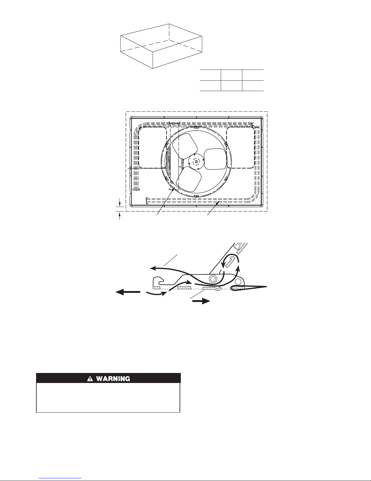
Fig. 6—Unit Leveling Tolerances
C99065
A
B
C
MAXIMUM ALLOWABLE
DIFFERENCE (in.)
A-B B-C A-C
1/4 1/4 1/4
Fig. 7—Slab Mounting Detail
C99096
OPTIONAL
RETURN
AIR
OPENING
OPTIONAL
SUPPLY
AIR
OPENING
EVAP. COIL COND. COIL
2"
Fig. 8—Threading Belt
C99067
HANDHOLD
FEED
HOOK
7
Page 8
If the installation requires draining the condensate water away
from the unit, install a field-supplied 2 -in. trap at the condensate
connection to ensure proper drainage. Condensate trap is available
as an accessory or is field-supplied. Make sure that the outlet of the
trap is at least 1 in. lower than the unit drain-pan condensate
connection to prevent the pan from overflowing. Connect a drain
trough using a minimum of field-supplied 3/4-in. PVC or fieldsupplied 3/4-in. copper pipe at outlet end of the 2-in. trap. (See Fig.
12) Do not undersize the tube. Pitch the drain trough downward at
a slope of at least 1 in. every 10 ft. of horizontal run. Be sure to
check the drain trough for leaks. Prime the trap at the beginning of
the cooling season start-up.
Step 7—Install Electrical Connections
The unit cabinet must have an uninterrupted, unbroken
electrical ground to minimize the possibility of personal
injury if an electrical fault should occur. This ground may
consist of an electrical wire connected to the unit ground lug
in the control compartment, or conduit approved for electrical
ground when installed in accordance with NEC, ANSI/NFPA
American National Standards Institute/National Fire Protection Association (latest edition) (in Canada, Canadian Electrical Code CSA C22.1) and local electrical codes. Failure to
adhere to this warning could result in serious injury or death.
Failure to follow these precautions could result in damage to
the unit being installed:
1. Make all electrical connections in accordance with NEC
ANSI/NFPA (latest edition) and local electrical codes
governing such wiring. In Canada, all electrical connections must be in accordance with CSA standard C22.1
Canadian Electrical Code Part 1 and applicable local
codes. Refer to unit wiring diagram.
2. Use only copper conductor for connections between
field-supplied electrical disconnect switch and unit. DO
NOT USE ALUMINUM WIRE.
3. Be sure that high-voltage power to unit is within operating
voltage range indicated on unit rating plate. On 3-phase
units, ensure phases are balanced within 2 percent. Consult
local power company for correction of improper voltage
and/or phase imbalance.
4. Insulate low-voltage wires for highest voltage contained
within conduit when low-voltage control wires are in same
conduit as high-voltage wires.
5. Do not damage internal components when drilling through
any panel to mount electrical hardware, conduit, etc.
HIGH-VOLTAGE CONNECTIONS
The unit must have a separate electrical service with a field-
supplied, waterproof disconnect switch mounted at, or within sight
from the unit. Refer to the unit rating plate, NEC and local codes
Fig. 9—Suggested Rigging
UNIT MAXIMUM SHIPPING WEIGHT A B
Size lb kg in. mm. in. mm.
50XZ024 372 169 19.0 482.6 18.25 463.6
50XZ030
Not
Yet
Available
“ ““““
50XZ036 395 179 20.0 508 19.0 482.6
50XZ042
Not
Yet
Available
“ ““““
50XZ048 485 220 20.0 508 21.25 539.8
50XZ060 521 236 21.0 533.4 20.0 508.0
C99075
PLACE RIGGING BRACKET ASSEMBLY IN 4
RIGGING HOLES AND INSTALL TIE DOWN STRAP
AROUND PERIMETER OF UNIT AND THROUGH
SPACE IN BRACKET ASSEMBLY
INSTALL SAFETY STRAPS TO
RIGGING CLEVIS AT 4 RIGGING BRACKETS
TIGHTEN STRAPPING SECURELY
WITH TENSION BUCKLE
SEE DETAIL A
DETAIL A
SCALE 0.250
914-137"
(36"-54")
“A”
“B”
8
Page 9
for maximum fuse/circuit breaker size and minimum circuit amps
(ampacity) for wire sizing (See Table 3 for electrical data).
The field-supplied disconnect may be mounted on the unit over the
high-voltage inlet hole (See Figs. 2 and 3).
If the unit has an electric heater, a second disconnect may be
required. Consult the Installation, Start-Up, and Service Instructions provided with the accessory for electrical service connections.
Operation of unit on improper line voltage constitutes abuse and
may cause unit damage that could affect warranty.
ROUTING POWER LEADS INTO UNIT
Use only copper wire between disconnect and unit. The high-
voltage leads should be in a conduit until they enter the duct panel;
conduit termination at the duct panel must be watertight. Run the
high-voltage leads through the power entry knockout on the power
entry side panel. (See Fig. 2 and 3 for location and size) When the
leads are inside the unit, run leads up the high-voltage raceway to
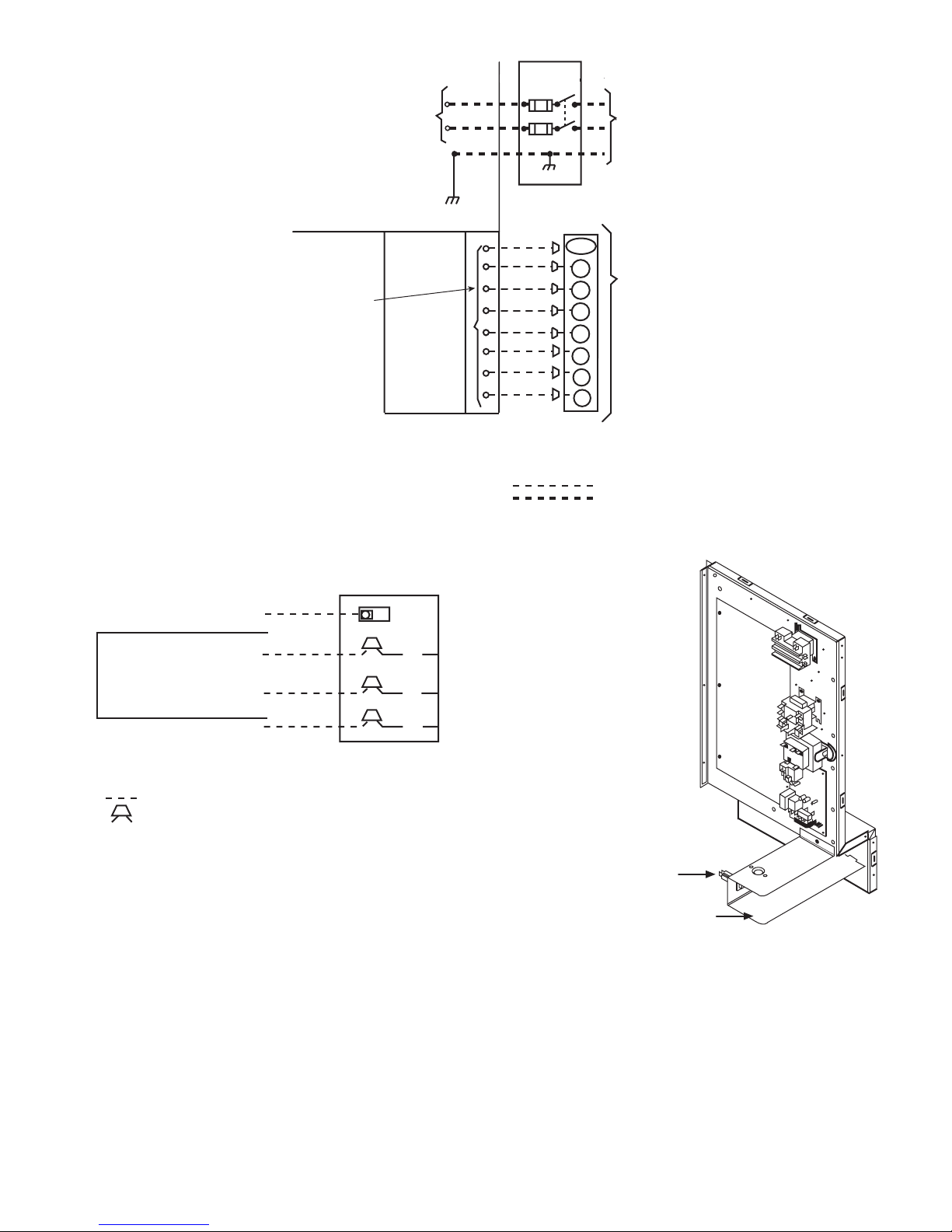
the line wiring splice box (See Fig. 13 through 17). For singlephase units, connect leads to the black and yellow wires; for
3-phase units, connect the leads to the black, yellow, and blue
wires.
CONNECTING GROUND LEAD TO GROUND LUG
Refer to Fig. 16 and 17. Connect the ground lead to the chassis
using the ground lug in the wiring splice box.
ROUTING CONTROL POWER WIRES (24-V)
Form a drip-loop with the thermostat leads before routing them
into the unit. Route the thermostat leads through grommeted,
low-voltage hole provided in unit into unit control power splice
box. (See Fig. 2 and 3) Connect thermostat leads to unit control
power leads as shown in Fig. 16.
The unit transformer supplies 24-v power for complete system
including accessory electrical heater. An automatic-reset circuit
breaker (See Fig. 18) is provided in the 24-v circuit; see the caution
label on the transformer or Fig. 19. Transformer is factory wired
for 230-v operation. If supply voltage is 208-v, rewire transformer
primary as described in Special Procedures for 208-v Operation
section.
EASY SELECT™—50XZ
EASY SELECT™ CONFIGURATION TAPS FOR 50XZ
Easy Select™ taps are used by the installer to configure a system.
The ECM motor uses the selected taps to modify its operation to
Table 1—Physical Data—Unit 50XZ
UNIT SIZE 50XZ024 50XZ030 50XZ036 50XZ042 50XZ048 50XZ060
NOMINAL CAPACITY (ton) 2
Not Yet
Available
3
Not Yet
Available
45
OPERATING WEIGHT (lb.) 350 “ 373 “ 463 499
COMPRESSOR QUANTITY 1
TYPE SCROLL COMPRESSOR
REFRIGERANT R-410A
REFRIGERANT METERING DEVICE
Indoor-TXV
Outdoor-Accurater
Refrigerant (R-410A) Quantity (lb.) 7.5 “ 9.5 “ 12.5 14.0
METERING DEVICE
ID
TXV “ TXV “ TXV TXV
ORIFICE OD (in.) 0.035 (2) “ 0.038 (2) “
0.038 (Left OD Coil)
0.046 (Right OD Coil)
0.042 (Left OD Coil)
0.052 (Right OD Coil)
OUTDOOR COIL
Rows... Fins/in.
face area (sq. ft.)
2...21
12.3
“
2...21
13.6
“
2...21
17.2
2...21
19.4
OUTDOOR FAN
Nominal Airflow (CFM)
Diameter
Motor HP (RPM)
2350
22
1/8 (825)
“
2800
22
1/8 (825)
“
3300
22
1/4 (1100)
3300
22
1/4 (1100)
INDOOR COIL
Rows... Fins/in.
face area (sq. ft.)
3...15
3.7
“
4...15
3.7
“
4...15
4.7
4...15
5.7
INDOOR BLOWER
Nominal Airflow (CFM)
Size (in.)
Motor (HP)
790
10x10
1/2
“
1100
11x10
3/4
“
1400
11x10
3/4
1750
11x10
1.0
HIGH-PRESSURE SWITCH (psig)
Cutout
Reset (Auto)
610±15
420±25
LOSS-OF-CHARGE/LOW-PRESSURE SWITCH
(Liquid Line) (psig)
Cutout
Reset (Auto)
20±5
45±10
RETURN-AIR FILTERS (in.)*
throwaway
20x20x1 “ 20x24x1 “ 24x30x1 24x30x1
* Required filter sizes shown are based on the larger of the ARI (Air Conditioning and Refrigeration Institute) rated cooling airflow or the heating airflow velocity of 300
ft/minute for throwaway type or 450 ft/minute for high-capacity type. Air filter pressure drop for non-standard filters must not exceed 0.08 in. wg.
Table 2—Minimum Airflow for Reliable Electric Heater Operation (Cfm)
SIZE 50XZ024 50XZ030 50XZ036 50XZ042 50XZ048 50XZ060
AIRFLOW (CFM) 750 1025 1250 1285 1710 1800
9
Page 10
a pre-programmed table of airflows.
The unit must be configured to operate properly with system
components with which it is installed. To successfully configure a
basic system (see information printed on circuit board label located
next to select pins), move the 6 select wires to the pins which
match the components used.
a. AUX HEAT kW/CFM—SELECT HEATER RANGE
FOR SIZE OF ELECTRIC HEATER INSTALLED
Installer must select the auxiliary heat airflow approved for
application with kW size heater installed. If no heater is
installed, this step can be skipped. Each select pin is
marked with a range of heaters for which airflow (also
marked), is approved. For increased comfort, select the
narrowest kW range matching the heater size, for example,
0–10 for 10–kW heater. This airflow must be greater than
the minimum for CFM for electric heater application with
the size system installed for safe and continuous operation.
(See Tables 4A, 4B, 4C,5&6forairflow delivery and
minimum CFM.) Note that airflow marked is the airflow
which will be supplied in emergency heat mode and
heating mode on air conditioners when electric heat is the
primary heating source. In heat pump heating mode when
electric heaters are energized, the ECM will run the higher
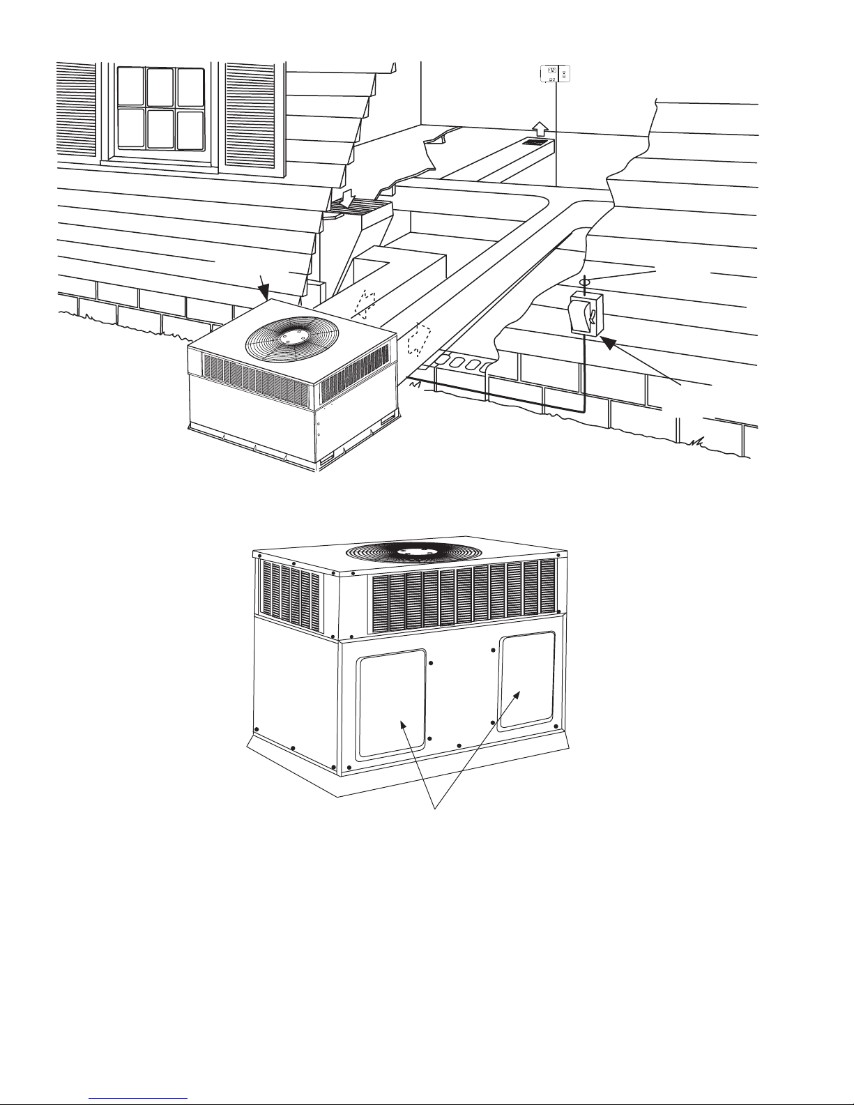
Fig. 10—Typical Installation
C00063
INDOOR
THERMOSTAT
DISCONNECT
PER NEC*
FROM
POWER
SOURCE
RETURN
AIR
TOP COVER
*NEC - NATIONAL ELECTRICAL CODE
Fig. 11—50XZ with Duct Covers On
C00092
Duct Covers
10
Page 11
of heat pump heating airflow and electric heater airflow to
ensure safe heater operation. The factory selection is the
largest heater range approved (See Fig. 20, A as indicated).
b. AC/HP SIZE—SELECT SYSTEM SIZE INSTALLED
The factory setting for air conditioner or heat pump size is
the size which matches the model of packaged unit
installed. Installer should verify air conditioner or heat
pump size to ensure that airflow delivered falls within
proper range for the size unit installed. This applies to all
operational modes with the exception of electric heat
modes (See Fig. 20, B as indicated).
c. SYSTEM TYPE—SELECT SYSTEM TYPE IN-
STALLED
The type of system will be factory selected (see below for
details):
(1.) AC-Air conditioner
(2.) HP-COMFORT—Heat Pump Comfort provides ap-
proximately 315 CFM per ton for higher normal
Fig. 12—Condensate Trap
C99013
1” (25mm) MIN.
2” (50mm) MIN.
TRAP
OUTLET
Table 3—Electrical Data—50XZ
UNIT 50XZ
SIZE
V-PH-HZ
VOLTAGE
RANGE
COMPRESSOR
ODFM
FLA
IDFM
FLA
ELECTRIC HEAT SINGLE POINT POWER SUPPLY
Min Max RLA LRA Nominal Kw* FLA UNIT MCA MAX FUSE OR CKT BKR MOCP
024 208/230–1–60 187 253 13.5 61.0 0.9 4.3
-/-
3.8/5.0
5.4/7.2
7.5/10.0
-/-
18.1/20.8
26/30
36.1/41.7
22.1/22.1
44.6/48.1
54.6/59.6
67.2/74.2
30/30
60/60
—
—
—
—
70/70
80/80
030 208/230–1–60 187 253 15.9 73.0 0.9 4.3
-/-
3.8/5.0
5.4/7.2
7.5/10.0
11.3/15.0
-/-
18.1/20.8
26/30
36.1/41.7
54.2/62.5
25.1/25.1
47.6/51.1
57.6/62.6
70.2/77.2
92.8/103.2
30/30
—
—
—
—
—
60/70
70/80
80/90
100/110
036
208/230–1–60 187 253 16.9 83.0 0.9 6.8
-/-
3.8/5.0
5.4/7.2
7.5/10.0
11.3/15.0
-/-
18.1/20.8
26/30
36.1/41.7
54.2/62.5
28.8/28.8
51.4/54.9
61.3/66.3
74.0/80.9
96.5/107.0
35/35
—
—
—
—
—
70/70
80/80
90/90
100/110
208/230–3–60 187 253 12.2 77.0 1.6 6.8
-/-
3.8/5.0
7.5/10.0
11.3/15.0
-/-
10.4/12.0
20.8/24.1
31.3/36.1
23.7/23.7
36.7/38.7
49.7/53.7
62.7/68.8
30/30
50/50
60/60
—
—
—
—
70/80
042
208/230–1–60 187 253 22.4 105.0 0.9 6.8
-/-
3.8/5.0
5.4/7.2
7.5/10.0
11.3/15.0
15.0/20.0
-/-
18.1/20.8
26/30
36.1/41.7
54.2/62.5
72.2/83.3
35.7/35.7
58.3/61.7
68.2/73.2
80.8/87.8
103.4/113.8
126.0/139.9
45/45
—
—
—
—
—
—
80/80
90/90
100/100
125/125
150/150
208/230–3–60 187 253 15.4 88.0 0.9 6.8
-/-
3.8/5.0
7.5/10.0
11.3/15.0
15.0/20.0
-/-
10.4/12.0
20.8/24.1
31.3/36.1
41.6/48.0
27.0/27.0
40.0/42.0
53.0/57.0
66./72.1
78.9/86.9
35/35
60/60
—
—
—
—
—
70/70
80/80
90/100
048
208/230–1–60 187 253 21.3 109.0 1.6 6.8
-/-
3.8/5.0
5.4/7.2
7.5/10.0
11.3/15.0
15.0/20.0
-/-
18.1/20.8
26/30
36.1/41.7
54.2/62.5
72.2/83.3
35.0/35.0
57.6/61.1
67.5/72.5
80.2/87.1
102.7/113.2
125.3/139.2
45/45
—
—
—
—
—
—
80/80
90/90
100/100
125/125
150/150
208/230–3–60 187 253 14.7 91.0 1.6 6.8
-/-
3.8/5.0
7.5/10.0
11.3/15.0
15.0/20.0
-/-
10.4/12.0
20.8/24.1
31.3/36.1
41.6/48.0
26.8/26.8
39.8/41.8
52.8/56.8
65.9/71.9
78.7/86.7
35/35
60/60
—
—
—
—
—
70/70
80/80
90/90
060
208/230–1–60 187 253 26.9 145.0 1.5 9.1
-/-
3.8/5.0
5.4/7.2
7.5/10.0
11.3/15.0
15.0/20.0
-/-
18.1/20.8
26/30
36.1/41.7
54.2/62.5
72.2/83.3
44.2/44.2
66.8/70.3
76.7/81.7
89.4/96.3
111.9/122.4
134.5/148.4
60/60
—
—
—
—
—
—
90/100
100/110
110/125
150/150
150/175
208/230–3–60 187 253 17.6 123.0 1.5 9.1
-/-
3.8/5.0
7.5/10.0
11.3/15.0
15.0/20.0
-/-
10.4/12.0
20.8/24.1
31.3/36.1
41.6/48.0
32.6/32.6
45.6/47.6
58.7/62.7
71.7/77.7
84.6/92.6
40/40
60/60
—
—
—
—
—
70/70
80/80
90/90
11
Page 12
heating air delivery temperature and provides approximately 350 CFM per ton cooling airflow for good
humidity removal.
(3.) HP-EFF (Factory Selected for 50XZ)— Heat Pump
Efficiency provides same airflow for heating and
cooling modes to increase overall HP efficiency;
approximately 350 CFM per ton.
d. AC/HP CFM ADJUST—SELECT NOMINAL, LOW, OR
HIGH AIRFLOW
The AC/HP CFM Adjust select is factory set to the
High-Hi (NOM for 060) tap. The CFM Adjust selections
NOM/LO will regulate airflow supplied for all operational
modes, except non-heat pump heating modes. HI provides
15 percent airflow over nominal unit size selected and LO
provides 10 percent airflow below nominal unit size
selected. CFM Adjust selection options are provided to
adjust airflow supplied to meet individual installation
needs for such things as noise, comfort, and humidity
removal (See Fig. 20, D as indicated).
e. ON/OFF DELAY—SELECT DESIRED
TIME DELAY PROFILE
Four motor operation delay profiles are provided to cus-
tomize and enhance system operation (See Fig. 20, E as
indicated).
Selection options are:
(1.) The standard 90 sec off delay (Factory Setting) at 100
percent airflow in cooling or heat pump heating mode.
(2.) A 30 sec cooling delay with no airflow, 90 sec off
delay at 100 percent airflow profile is used when it is
desirable to allow system coils time to heat-up/cooldown in conjunction with the airflow in cooling or
heat pump heating mode.
(3.) A no delay option used for servicing unit or when a
thermostat is utilized to perform delay functions.
(4.) ENH, enhanced selection, provides a 30 sec cooling on
delay with no airflow, plus 150 sec at 70 percent
airflow and no off delay for added comfort.
This will minimize cold blow in heat pump operation
and could enhance system efficiency.
f. CONTINUOUS FAN—SELECT DESIRED FAN SPEED
WHEN THERMOSTAT IS SET ON CONTINUOUS FAN
(1.) LO speed—Factory setting, 50 percent cooling mode
airflow.
(2.) MED speed—Move connector to MED, 65 percent
cooling mode airflow.
(3.) HI speed—Move connector to HI, 100 percent cooling
mode airflow (See Fig. 20, F as indicated).
g. LOW-VOLTAGE CIRCUIT FUSING AND REFER-
ENCE
The low-voltage circuit is fused by a board-mounted
5–amp automotive fuse placed in series with the transformer SEC2 and the R circuit. The C circuit of the
transformer is referenced to chassis ground through a
printed circuit run at SEC1 connected to metal standoff
marked with ground symbol.
h. BASIC UNIT CONFIGURATION
The following basic configuration of the indoor motor will
provide ARI rated performance of the System. This BASIC
CONFIGURATION should be used when the rated ARI
performance is required, or if system enhancements such
as super dehumidify are not needed.
(1.) AUX HEAT kW/CFM-Select the heater range for the
size of electric heater installed (skip this step if no
heater is installed).
(2.) AC/HP SIZE-Factory selected to match system size
installed, please verify.
(3.) SYSTEM TYPE-Factory selected HP-EFF (for unit
50XZ).
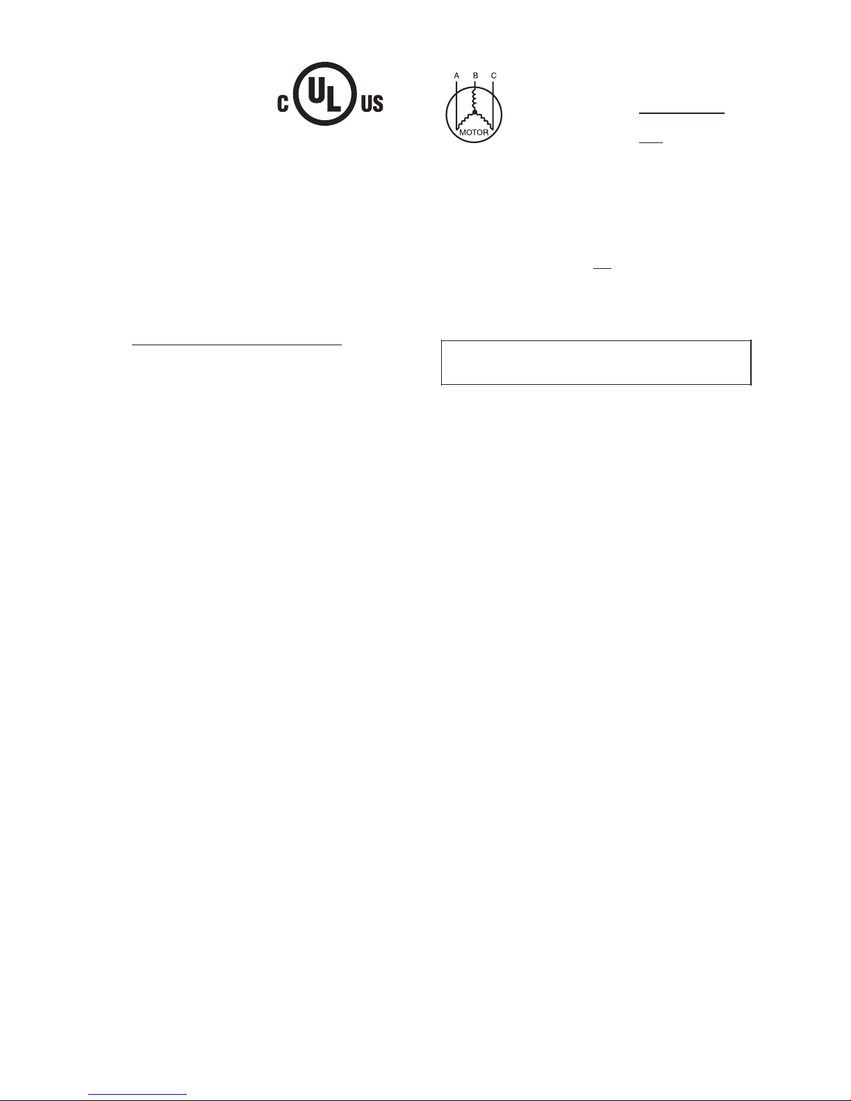
Fig. 13—Electrical Data Legend
C03014
228 =1v
229 =2v
227 =2v
LEGEND
FLA — Full Load Amps
LRA — Locked Rotor Amps
MCA -- Minimum Circuit Amps
MOCP — Maximum Overcurrent Protection
RLA — Rated Load Amps
NO TES:
1. In compliance with NEC (National Electrical Code) requirements
for multimotor and combination load equipment (refer to NE C
Articles 430 and 440), the overcurrent protective device for the
unit shall be Power Supply fuse. The CGA (Canadian Gas
Association) units may be fuse or circuit break er.
2. Minimum wire size is based on 60 C copper wire. I f other than
60 C wire is used, or if length exceeds wire length in table,
determine siz e from NEC..
3. Unbalanced 3-Phase Supply Voltage
Never operate a motor where a phase imbalance in supply voltage is greater than 2%.
Use the following formula to determine
the percentage of voltage imbalance.
% Voltage imbalance
max voltage deviation from average voltage
= 100 x
average voltage
EXAMPLE: Supply voltage is 230-3-60.
AB = 228 v
BC = 231 v
AC = 227 v
228 + 231 + 227
Average Voltage =
3
686
=
3
= 229
Determine maximum deviation from average voltage.
(AB) 229 (BC) 231 -
(AC) 229 Maximum deviation is 2 v.
Determine percent of voltage imbalance.
2
% Voltage Imbalance = 100 x
229
= 0.8%
This amount of phase imbalance is satisfactory as it is below the
maximum allowable 2%.
IMPORTANT: If the supply voltage phase imbalance is
more than 2%, contact your local electric utility company
immediately.
®
*
Heater capacity (kW) based on heater voltage of 208v & 240v.
If power distibution voltage to unit varies from rated heater
voltage, heater kW will vary accordingly.
12
Page 13
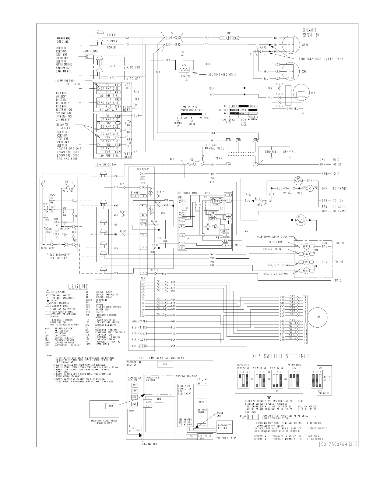
Fig. 14—Wiring Schematics-50XZ Single Phase
C03005
13
Page 14
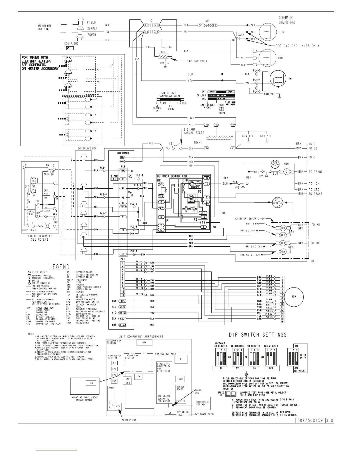
Fig. 15—Wiring Schematics-50XZ Three Phase
1
3
2
14
C03006
Page 15
(4.) AC/HP CFM ADJUST-Select HIGH for 042 & 048,
NOM for 036 & 060, and LO for 024 & 030.
(5.) ON/OFF DELAY-Select 0/90 profile.
(6.) CONTINUOUS FAN-Select desired fan speed when
thermostat is set to continuous fan.
i. COMFORT OPTIONS—SUPER DEHUMIDIFY (See
Quick Reference Guide)
The Super Dehumidify option is possible when this unit is
installed with a field supplied Thermidistat™ control (Super Dehumidify does not require an outdoor temperature
sensor). The following configuration is recommended for
maximum cooling/dehumidifying comfort: This configuration will improve the comfort provided by the air conditioning system if more humidity removal is desired. While
providing this improved comfort, the system will operate
efficiently, but not at the published HSPF or ARI SEER
efficiency.
The following system configuration is recommended for
maximum heating and cooling/dehumidifying comfort (See
Fig. 20–22).
(1.) AUX HEAT kW/CFM-Select the narrowest heater
range to match size of electric heater installed (skip
this step if no heater is installed).
(2.) AC/HP Size-Factory selected to match system size
installed, please verify.
(3.) SYSTEM TYPE-Select system type HP-COMFORT
(for heat pump system) or AC (for air conditioner
system).
Fig. 16—High and Control Voltage Wiring Connections
C01028
POWER
SUPPLY
FIELD-SUPPLIED
FUSED DISCONNECT
HIGH VOLT AGE
POWER LEADS
(SEE UNIT WIRING
LABEL)
GND
CONTROL BOX
SPLICE BOX
LOW-VOLTAGE
POWER LEADS
(SEE UNIT
WIRING LABEL)
YEL(Y)
GRN(G)
RED(R)
BRN(C)
THERMOSTAT
(TYPICAL)
LEGEND
Field Control-Voltage Wiring
Field High-Voltage Wiring
BLK(DH)
DHUM
Y
G
R
C
W1
WHI(W1)
GRA(W2)
W2
ORN(0)
O
Fig. 17—Line Power Connections
C99057
GROUND LUG
(IN SLPICE BOX)
BLU
YEL
BLK
GROUND
LEAD
SINGLE-PHASE
CONNECTIONS
TO DISCONNECT
PER NEC
3-PHASE
CONNECTIONS
LEGEND
NEC – National Electrical Code
Field Wiring
Splice Connections
NOTE: Use copper wire only.
L1
L3
L2
Fig. 18—Control Wiring Plate
C99070
24 V Circuit Breaker
24 V olt Compartment
15
Page 16
(4.) AC/HP CFM ADJUST-Select NOM (Lo for 060).
(5.) ON/OFF DELAY-Select ENH profile.
(6.) CONTINUOUS FAN-Select desired fan speed when
thermostat is set to continuous fan.
(7.) DEHUMIDIFY MODE-Remove J1 jumper to activate.
(8.) LOW VOLTAGE CONNECTIONS-Make connec-
tions as shown in ELECTRICAL CONNECTIONS
section.
(9.) CONFIGURE THERMIDISTAT™ (or capable zoning
system)-Following its installation instructions for Su-
per Dehumidify and Super Comfort Heat operation.
This configuration provides the following comfort enhance-
ments:
(a.) A 30 sec blower on delay with 150 sec at 70
percent airflow to allow the indoor coil to warm
up or cool down before the blower is asked to
deliver 100 percent airflow reducing the cold blow
sensation at start up in heating and allowing the
indoor coil to more quickly reach wet coil operating conditions in cooling.
(b.) A no blower off delay eliminates cold blow which
may be associated with running the blower after
shut down of the compressor and avoids reevaporation of condensed moisture after
cooling/dehumidifying operation.
(c.) Lower airflow while the compressor is running to
reduce draft effects and increase heating air temperature and improved humidity control during
cooling operation.
ACCESSORY INSTALLATION
a. ACCESSORY ELECTRIC HEATERS
Electric heaters may be installed with the 50XZ units per
instructions supplied with electric heater package. See unit
rating plate for factory-approved electric heater kits.
b. AUXILIARY TERMINALS
The AUX and HUM terminals on the Easy Select™ Board
are tied directly to the G terminal, and provide a 24-v.
signal whenever the G terminal is energized (See Fig. 20).
During Super dehumidify mode, the G signal is not present
and the auxiliary terminals are not energized. If the
installation includes the use of the operating mode, do not
use these terminals to control accessories. See Electronic
Air Cleaner and Humidifier sections for further information.
c. ELECTRONIC AIR CLEANER CONNECTIONS
The AUX1 and AUX2 terminals are not always energized
during blower operations, as described above. When using
an electronic air cleaner with the unit, use Airflow Sensor
P/N KEAAC0101AAA. The airflow sensor turns on electronic air cleaner when the blower is operating.
d. HUMIDIFIER/HUMIDISTAT CONNECTIONS
Easy Select™ Board terminals HUM1 and HUM2 are
provided for direct connection to the low-voltage control of
a humidifier through a standard humidistat (See Fig.
20–22). These terminals are energized with 24-v. when G
thermostat signal is present. (See Fig. 20–22). Alternately,
the 24-v. signal may be sourced from the W and C circuit
board connections. When using a Thermidistat™ Control,
Zone Comfort Plus or Comfort Zone II, the 24-v. signal
may be sourced directly from the Thermidistat™ HUM
terminal.
e. DEHUMIDIFY CAPABILITY WITH STANDARD
HUMIDISTAT CONNECTION
Latent capacities for these units are better than average
systems. If increased latent capacity is an application
requirement, the circuit board provides connection terminals for use of a standard humidistat. The unit will detect
the humidistat contacts opening on increasing humidity and
reduce its airflow to approximately 80 percent of nominal
cooling mode airflow. This reduction will increase the
system latent capacity until the humidity falls to a level
which causes the humidistat to close its contacts. When the
Fig. 19—Transformer Label
C99058
TRANSFORMER CONTAINS A MANUAL
RESET OVERCURRENT PROTECTOR
IT WILL NOT AUTOMATICALLY RESET
DISCONNECT POWER AND INSTALL
LOCKOUT TAG PRIOR TO SERVICING
THIS COMPARTMENT MUST BE CLOSED
EXCEPT WHEN SERVICING
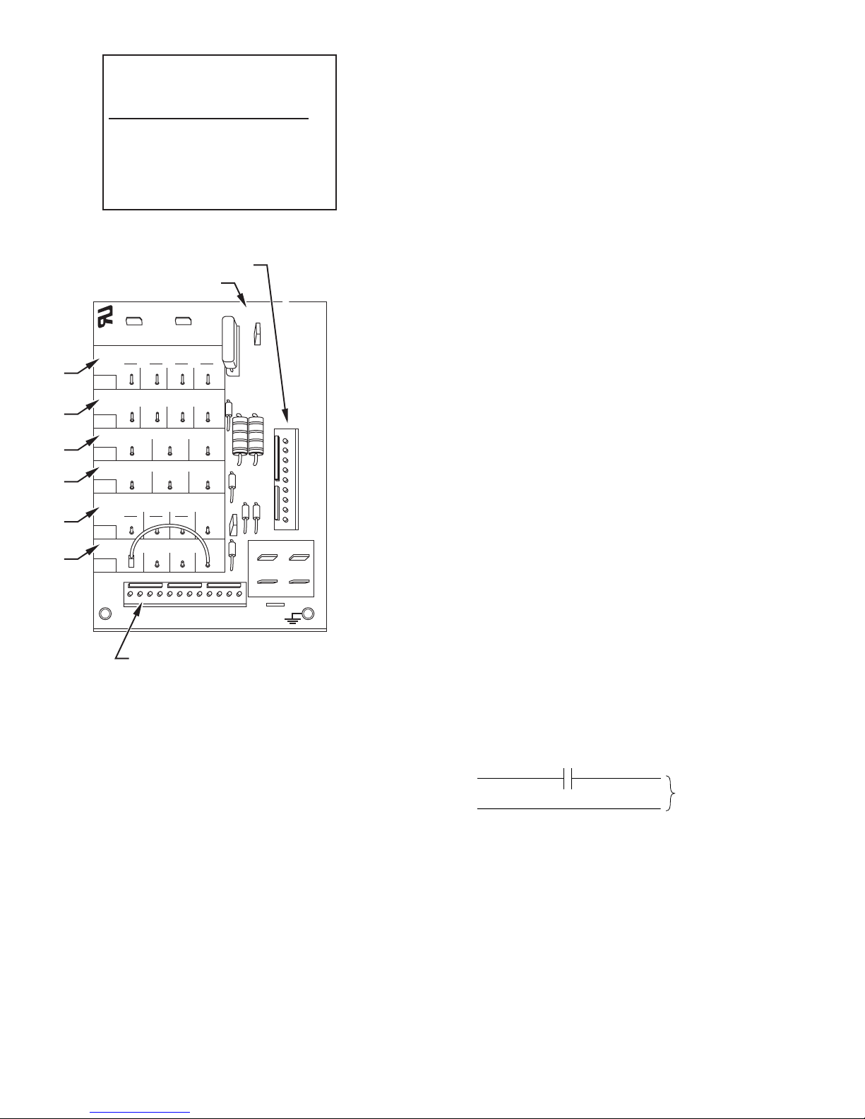
Fig. 20—Detail of SPP Printed-Circuit Board
C01033
EASY SELECT
HEATER/MOTOR
AUX HEAT KW/CFM
0-30
1075
SEC1 SEC2
J1
AC/HP SIZE
036 030 024 018
AC
HP-COMFORT
HP-EFF
NOM HI
ENH
LO
SYSTEM TYPE
AC/HP CFM ADJUST
ON/OFF DELAY
CONTINUOUS FAN
MED HI YELLO
AUX1 HUM1
AUX2
24VAC
GRY
HUM2
YEL
WHT
BLK
ORN
BLU
VIO
0-20
875
0-10
725
09030900
0
0-5
625
TM
J2
D
H
R
W
1
W
2
Y
1
Y/Y
2
G
O
C
9 PIN CONNECTOR
ICM PRINTED CIRCUIT BOARD
12 PIN CONNECTOR
A
B
C
D
E
F
Fig. 21—Humidifier Wiring for 50XZ
A95317
HUMIDISTAT
TO HUMIDIFIER
HUMIDIFIER WIRING
HUM 1
(C)
HUM 2
(G)
24-VAC
16
Page 17
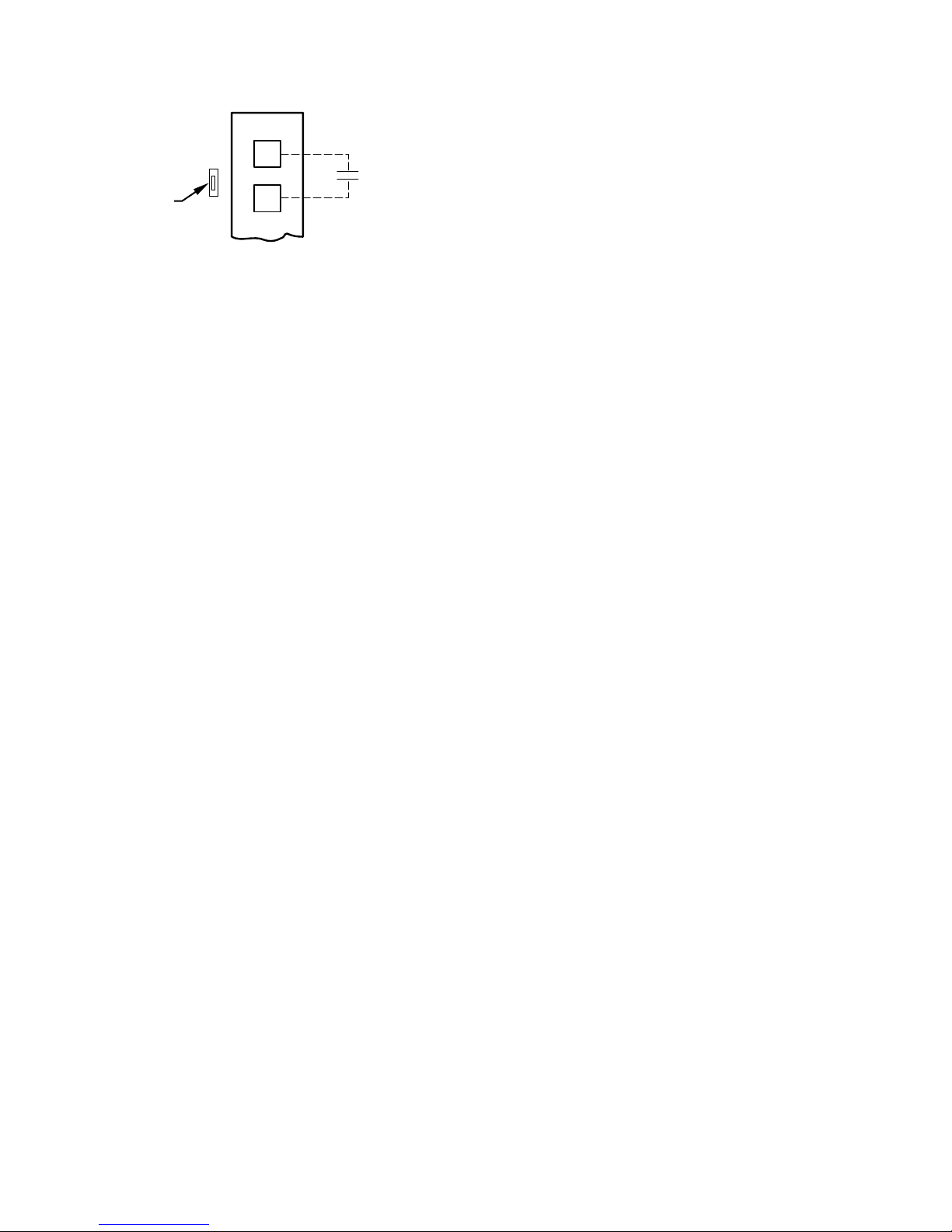
contacts close, the airflow will return to 100 percent of
selected cooling airflow. To activate this mode, remove
jumper J1 and wire in a standard humidistat (See Fig.
20–22).
f. DEHUMIDIFY AND SUPER DEHUMIDIFY CAPABILI-
TIES
these models are capable of responding to a signal from
indoor system control (thermostat, Thermidistat™, zoning
control) to operate in comfort control modes such as Super
Dehumidify Mode. Consult literature provided with indoor
system control to determine if these operating modes are
available, and to see control set up instructions. No special
setup or wiring of unit is required.
50XZ SEQUENCE OF OPERATION
a. CONTINUOUS FAN
(1.) Thermostat closes circuit R to G—The Blower runs at
continuous fan airflow.
b. COOLING MODE-LOW HUMIDITY
(1.) If indoor temperature is above temperature set point
and humidity is below humidity set point, thermostat
closes circuits R to G, R to Y/Y2 and R to O—The
unit delivers cooling airflow.
c. COOLING MODE-DEHUMIDIFICATION
(1.) If indoor temperature is above temperature set point
and humidity is above humidity set point, thermostat
or Thermidistat™ closes circuits R to G, R to O, and
R to Y/Y2 and humidistat or Thermidistat™ opens R
to DH—The unit delivers airflow which is approximately 80 percent of the nominal cooling airflow to
increase the latent capacity of the system.
d. COOLING MODE-SUPER DEHUMIDIFY OPERATION
(see quick reference guide)
NOTE: The indoor control used, such as a Thermidistat™, must
be capable of providing Super Dehumidify operation mode and
control must be configured as outlined in its installation instructions. Consult indoor control literature to determine if control is
capable of providing Super Dehumidify inputs and for configuration instruction.
(1.) If the indoor temperature is below the temperature set
point and the humidity is above the humidity set point,
the Thermidistat™ closes circuit R to O, opens circuits R to DH and R to G, and cycles circuit R to
Y/Y2. If circuit R to G is closed (24-v.), the motor will
deliver airflow at the full cooling or cooling plus
dehumidify mode requested value. If circuit R to G is
open (0–v.) for super dehumidify mode, the motor
delivers reduced airflow to maximize the humidity
removal of the system while minimizing over cooling.
e. ELECTRIC HEATING MODE
(1.) Thermostat closes circuit R to W/W1, or W2—The
unit delivers the selected electric heat airflow. There
are no on or off delays.
f. HEAT PUMP HEATING MODE
(1.) Thermostat closes circuits R to G and R to Y/Y2—The
unit delivers selected heat pump heating airflow.
g. HEAT PUMP HEATING WITH AUXILIARY
ELECTRIC HEAT
(1.) Thermostat closes circuits R to G, R to Y/Y2 and R to
W/W1 or W2 (and R to O in the case of defrost).
In the event that electric heating is called for by the
thermostat while the heat pump is also operating in either
heating or defrost modes, the motor will modify its airflow
output, if necessary, to provide an airflow which is defined
as safe for the operation of the electric heater during heat
pump operation. That airflow is the greater of the heat
pump heating airflow and the electric heater only airflow.
h. HEATING MODE—SUPER COMFORT HEAT OPERA-
TION
NOTE: The indoor control used, such as a Thermidistat™, must
be capable of providing Super Comfort Heat operation mode and
control must be configured as outlined in its installation instructions. The system must be installed with appropriate outdoor
temperature sensor. Consult indoor control literature to determine
if control is capable and for configuration instructions. Consult
indoor control instructions and sensor instructions for sensor
installation details.
If the outdoor temperature is in the range of 12° to 40° F, the
Thermidistat™ closes circuit R to Y/Y2 and opens circuit R to G.
If circuit R to G is closed (24-v.), the motor will deliver airflow at
the full heating requested value. If circuit R to G is open (0-v.) for
maximum heating comfort, the motor delivers reduced airflow to
maximize the temperature and minimize the draft effect of the
heated air leaving the unit.
SPECIAL PROCEDURES FOR 208-V OPERATION
1. Be sure unit disconnect switch is open.
2. Disconnect the yellow primary lead (w 110) from the transformer. See unit wiring label. (See Fig. 14 or 15 and 18)
3. Connect the yellow primary lead (w110) to the transformer
terminal labeled 200-v.
Fig. 22—Humidistat Wiring for De-Humidify Mode-
for 50XZ
A95316
EASY SELECT
BOARD TERMINAL
BLOCK
D
H
J1
R
HUMIDISTAT
REMOVE
JUMPER
17
Page 18
PRE-START-UP
Failure to observe the following warnings could result in
serious personal injury or death:
1. Follow recognized safety practices and wear protective
goggles when checking or servicing refrigerant system.
2. Do not operate compressor or provide any electric power to
unit unless compressor terminal cover is in place and
secured.
3. Do not remove compressor terminal cover until all electrical sources are disconnected.
4. Relieve and recover all refrigerant from both high- and
low-pressure sides of system before touching or disturbing
anything inside terminal box if refrigerant leak is suspected
around compressor terminals.
5. Never attempt to repair soldered connection while refrigerant system is under pressure.
6. Do not use torch to remove any component. System
contains oil and refrigerant under pressure.
To remove a component, wear protective goggles and
proceed as follows:
a. Shut off electrical power to unit.
b. Relieve and reclaim all refrigerant from system using
both high- and low-pressure ports.
c. Cut component connecting tubing with tubing cutter and
remove component from unit.
d. Carefully unsweat remaining tubing stubs when neces-
sary. Oil can ignite when exposed to torch flame.
Use the Start-Up Checklist supplied at the end of this book and
proceed as follows to inspect and prepare the unit for initial
start-up:
1. Remove all access panels.
2. Read and follow instructions on all DANGER, WARNING,
CAUTION, and INFORMATION labels attached to, or
shipped with, unit.
3. Make the following inspections:
a. Inspect for shipping and handling damages such as broken
lines, loose parts, disconnected wires, etc.
b. Inspect for oil at all refrigerant tubing connections and on
unit base. Detecting oil generally indicates a refrigerant
leak. Leak-test all refrigerant tubing connections using
electronic leak detector, or liquid-soap solution. If a refrigerant leak is detected, see following Check for Refrigerant
Leaks section.
c. Inspect all field and factory-wiring connections. Be sure
that connections are completed and tight.
d. Inspect coil fins. If damaged during shipping and handling,
carefully straighten fins with a fin comb.
4. Verify the following conditions:
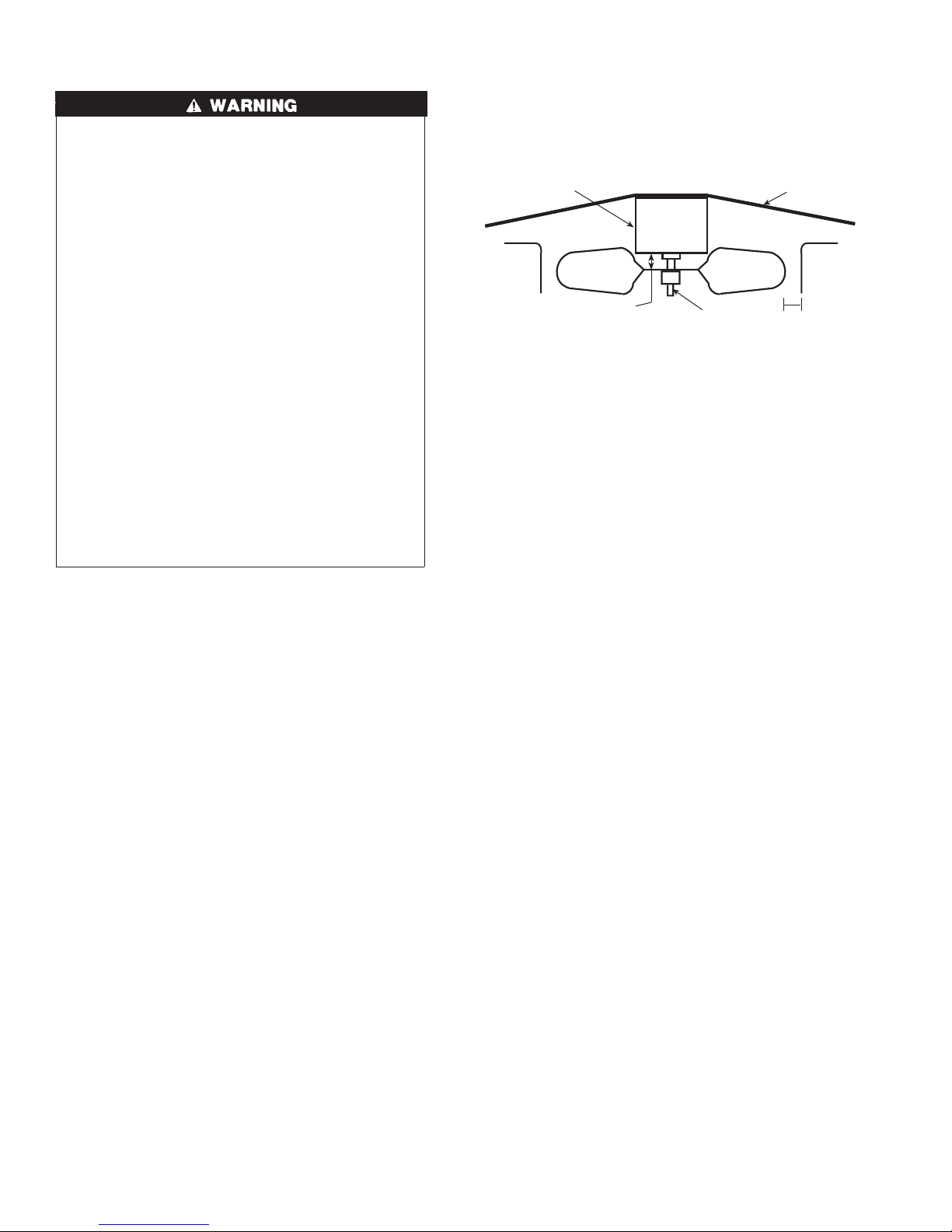
a. Make sure that outdoor-fan blade is correctly positioned in
fan orifice.
b. Make sure that air filter(s) is in place.
c. Make sure that condensate drain pan and trap are filled with
water to ensure proper drainage.
d. Make sure that – on the 060 size, only – the 2 wire ties
fastened to the outdoor coils and reversing
valve/accumulator have been removed.
e. Make sure that all tools and miscellaneous loose parts have
been removed.
5. Compressors are internally spring mounted. Do not loosen or
remove compressor hold-down bolts.
6. Each unit system has 2 Schrader-type ports, one low-side
Schrader fitting located on the suction line, and one high-side
Schrader fitting located on the compressor discharge line. Be
sure that caps on the ports are tight.
START-UP
Step 1—50XZ: Start-Up
CHECKING COOLING AND HEATING CONTROL OPERATION– Start and check the unit for proper control operation as
follows:
(1.) Place room thermostat SYSTEM switch or MODE
control in OFF position. Observe that blower motor
starts when FAN mode is placed in FAN ON position
and shuts down according to time delay selected on the
Easy Select™ board (See Easy Select Section) when
FAN MODE switch is placed in AUTO position.
(2.) Thermostat:
When the room temperature rises to a point that is
slightly above the cooling control setting of the
thermostat, the thermostat completes the circuit between thermostat terminal R to terminals Y, O and G.
These completed circuits through the thermostat connect contactor coil (C) (through unit wire Y) and ECM
board (through unit wire G) across the 24-v. secondary
of transformer (TRAN).
Thermidistat™ or Thermostat and Humidistat:
When the room temperature rises to a point that is
slightly above the cooling control setting of the
thermostat, the thermostat completes the circuit between thermostat terminal R to terminals Y, O, DH,
and G. These completed circuits through the thermostat connect contactor coil (C) (through unit wire Y)
and ECM board (though unit wire G) across the 24-v.
secondary of transformer (TRANS).
(3.) Place system switch or MODE control in HEAT
position. Set control above room temperature. Observe
that compressor, outdoor fan, and indoor blower
motors start. Observe that heating cycle shuts down
according to time delay selected on the Easy Select™
board (See Easy Select Section) when control setting
is satisfied.
(4.) When using an automatic changeover room thermo-
stat, place both SYSTEM or MODE control and FAN
mode switches in AUTO positions. Observe that unit
operates in Cooling mode when temperature control is
set to “call for Cooling” (below room temperature),
and unit operates in Heating mode when temperature
control is set to “call for Heating” (above room
temperature).
Fig. 23—Fan Blade Clearance
C99009
FAN GRILLE
MOTOR
1/8" MAX BETWEEN
MOTORAND FAN HUB
MOTOR SHAFT
1/2˝
18
Page 19
NOTE: Once the compressor has started and then has stopped, it
should not be started again until 5 minutes have elapsed. The
cooling cycle remains ‘‘on’’ until the room temperature drops to
point that is slightly below the cooling control setting of the room
thermostat. At this point, the thermostat ‘‘breaks’’ the circuit
between thermostat terminal R to terminals Y and G. These open
circuits de-energize contactor coil C and ECM board. The
condenser and compressor motors stop. After the time delay
setting selected on the Easy Select™ board (See Easy Select
Section) , the blower motor stops. The unit is in a ‘‘standby’’
condition, waiting for the next ‘‘call for cooling’’ from the room
thermostat. The 5 minute compressor delay also applies to heat
pump heating mode.
Step 2—Check for Refrigerant Leaks
Locate and repair refrigerant leaks and charge the unit as follows:
1. Use both high- and low-pressure ports to relieve system
pressure and reclaim remaining refrigerant.
2. Repair leak following accepted practices.
NOTE: Install a bi-flow filter drier whenever the system has been
opened for repair.
3. Check system for leaks using an approved method.
4. Evacuate refrigerant system and reclaim refrigerant if no
additional leaks are found.
5. Charge unit with R-410A refrigerant, using a volumetriccharging cylinder or accurate scale. Refer to unit rating plate
for required charge.
Step 3—Start-Up Adjustments
Complete the required procedures given in the Pre-Start-Up
section before starting the unit. Do not jumper any safety devices
when operating the unit. Do not operate the unit in Cooling mode
when the outdoor temperature is below 40°F (unless accessory
low-ambient kit is installed). Do not rapid-cycle the compressor.
Allow 5 min. between “on” cycles to prevent compressor damage.
CHECKING COOLING AND HEATING CONTROL OPERATION
Start and check the unit for proper control operation as follows:
1. Place room thermostat SYSTEM switch or MODE control in
OFF position. Observe that blower motor starts when FAN
mode is placed in FAN ON position and shuts down within 60
sec (030-060 size) or 30 sec (024 size) when FAN MODE
switch is placed in AUTO position.
2. Place system switch or MODE control in HEAT position. Set
control above room temperature. Observe that compressor,
outdoor fan, and indoor blower motors start. Observe that
heating cycle shuts down when control setting is satisfied.
3. When using an automatic changeover room thermostat, place
both SYSTEM or MODE control and FAN mode switches in
AUTO positions. Observe that unit operates in Cooling mode
when temperature control is set to “call for Cooling” (below
room temperature), and unit operates in Heating mode when
temperature control is set to “call for Heating” (above room
temperature).
IMPORTANT: Three-phase, scroll compressors are direction oriented. Unit must be checked to ensure proper compressor 3-phase
power lead orientation. If not corrected within 5 minutes, the
internal protector will shut off the compressor. The 3-phase power
leads to the unit must be reversed to correct rotation. When turning
backwards, the difference between compressor suction and discharge pressures may be dramatically lower than normal.
CHECKING AND ADJUSTING REFRIGERANT CHARGE
The refrigerant system is fully charged with R-410A refrigerant
and is tested and factory sealed.
NOTE: Adjustment of the refrigerant charge is not required
unless the unit is suspected of not having the proper R-410A
charge. The charging label and the tables shown refer to system
temperatures and pressures in Cooling mode, only. A refrigerant
charging label is attached to the outside of the service access door.
If charge level is suspect in Heating mode, reclaim all refrigerant
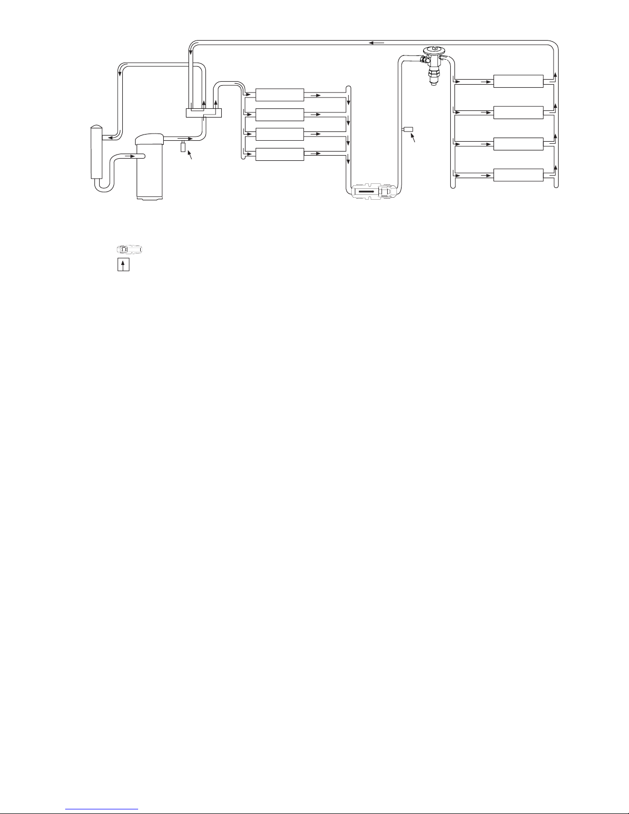
Fig. 24—Typical Heat Pump Operation, Cooling Mode
C03011
COMPRESSOR
ACCUMULATOR
OUTDOOR COIL
INDOOR COIL
LCS
LEGEND
HPS – High Pressure Switch
LCS – Loss of Charge Switch
Accurater
®
Metering De vice
Arrow indicates direction of flo w
TXV in Metering
Position
Bypass
Position
HP S
19
Page 20
and charge to nameplate amount. (This information may be
obtained from the physical data table also.) The charging label and
the tables shown refer to system temperatures and pressures in
Cooling mode only. A refrigerant charging label is attached to the
outside of the service access door. If charge level is suspect in
Heating mode, reclaim all refrigerant and charge to nameplate
amount. (This information may be obtained from the physical data
table also.)
IMPORTANT: When evaluating the refrigerant charge, an indicated adjustment to the specified factory charge must always be
very minimal. If a substantial adjustment is indicated, an abnormal
condition exists somewhere in the cooling system, such as insufficient airflow across either coil or both coils.
REFRIGERANT CHARGE
The amount of refrigerant charge is listed on the unit nameplate
and/or the physical data table. Refer to the Refrigeration Service
Techniques Manual, Refrigerants Section.
NO CHARGE
Check for leak. Use standard evacuating techniques. After evacu-
ating system, weigh in the specified amount of refrigerant (refer to
system data plate).
LOW CHARGE COOLING
Use Cooling Charging Chart (Fig. 27). Vary refrigerant until the
conditions of the chart are met. Note that charging charts are
different from type normally used. Charts are based on charging
the units to correct subcooling for the various operating conditions.
Accurate pressure gauge and temperature sensing devices are
required. Connect the pressure gauge to the service port on the
suction line. Mount the temperature sensing device on the suction
line and insulate it so that the outdoor ambient does not affect the
reading. Indoor air CFM must be within the normal operating
range of the unit.
TO USE COOLING CHARGING CHARTS
Take the liquid line temperature and read the manifold pressure
gauges. Refer to the chart to determine what the liquid line
temperature should be.
NOTE: If the problem causing the inaccurate readings is a
refrigerant leak, refer to Check for Refrigerant Leaks section.
INDOOR AIRFLOW AND AIRFLOW ADJUSTMENTS
For heating and cooling operation, the recommended airflow
is 350 to 450 cfm for each 12,000 Btuh of rated cooling
capacity. For units with optional electric heat, the airflow
must not be reduced below the levels stated in Table 2.
Tables 4A & 4B show both heating and cooling airflows. Refer to
these tables to determine the airflow for the system being installed.
NOTE: Be sure that all supply-and return-air grilles are open, free
from obstructions, and adjusted properly.
Airflow can be changed by changing the set up pins on the Easy
Select™ board.
Unit 50XZ utilizes state of the art ECM (Electronic Computated
Motor) ID Blower Motors.
Step 4—Defrost Control
QUIET SHIFT
Quiet Shift is a field-selectable defrost mode, which will eliminate
occasional noise that could be heard at the start of defrost cycle
and restarting of heating cycle. It is selected by placing DIP switch
3 (on defrost board) in ON position.
When Quiet Shift switch is placed in ON position, and a defrost is
initiated, the following sequence of operation will occur. Reversing valve will energize, outdoor fan will turn off, compressor will
turn off for 30 sec and then turn back on to complete defrost. At
the start of heating after conclusion of defrost reversing valve will
de-energize, compressor will turn off for another 30 sec, and the
outdoor fan will stay off for 40 sec, before starting in the Heating
mode.
DEFROST
The defrost control is a time/temperature control which includes a
field-selectable time period (DIP switch 1 and 2 on the board)
between defrost cycles of 30, 60, 90, or 120 minutes (factory set at
30 minutes).
To initiate a forced defrost, two options are available depending on
the status of the defrost thermostat.
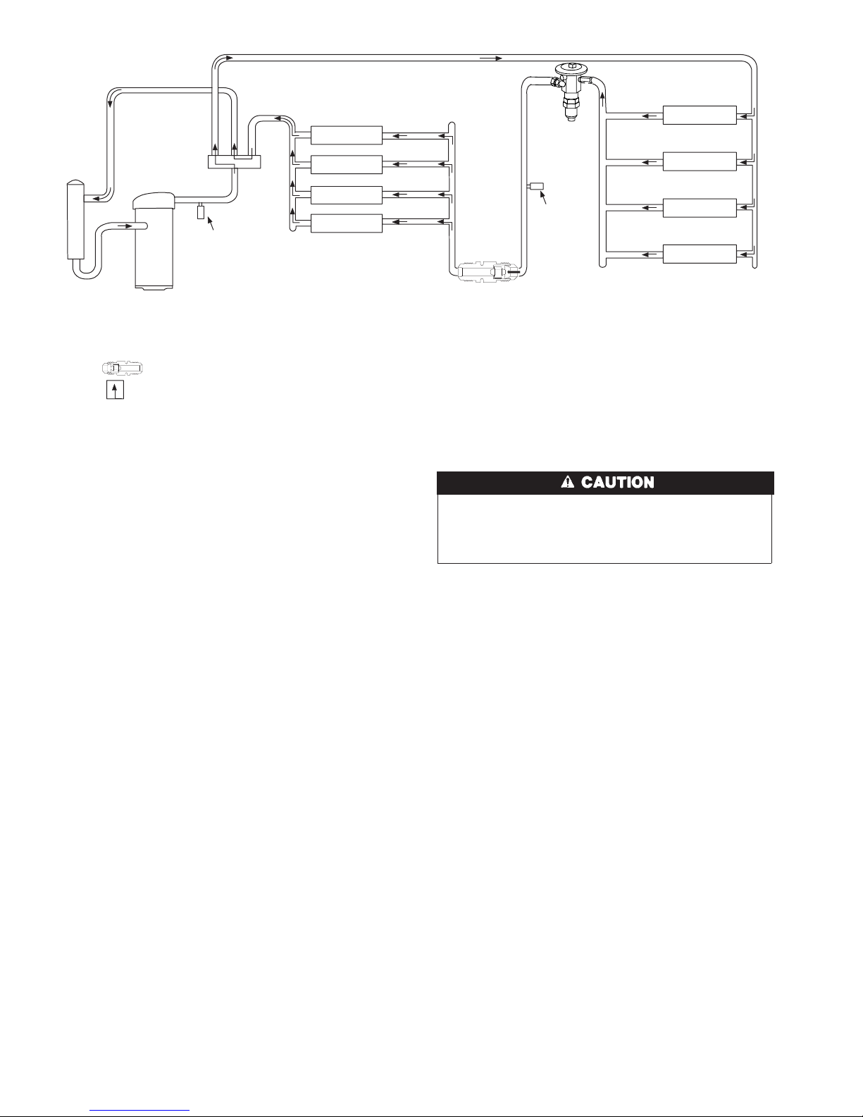
Fig. 25—Typical Heat Pump Operation, Heating Mode
C03012
COMPRESSOR
ACCUMULATOR
OUTDOOR COIL
INDOOR COIL
LCS
LEGEND
HPS – High Pressure Switch
LCS – Loss of Charge Switch
Accurater
®
Metering De vice
Arrow indicates direction of flo w
TXV in Bypass
Position
Metering
Position
HP S
20
Page 21
If defrost thermostat is closed, speedup pins (J1) must be shorted
by placing a flat head screw driver in between for 5 sec and
releasing, to observe a complete defrost cycle. When the Quiet
Shift switch is selected, compressor will be turned off for two 30
sec intervals during this complete defrost cycle, as explained
previously. When Quiet Shift switch is in factory default OFF
position, a normal and complete defrost cycle will be observed.
If defrost thermostat is in open position, and speedup pins are
shorted (with a flat head screw driver) for 5 sec and released,a
short defrost cycle will be observed (actual length is dependent
upon the selected Quiet Shift position). When Quiet Shift switch is
in ON position, the length of defrost is 1 minute (30 sec
compressor off period followed by 30 sec of defrost with compressor operation). On return to heating operation, compressor will
Table 4A—50XZ Cooling & Heating Dry Coil ECM Airflow
Small Cabinet
UNIT
SIZE
CFM ADJUST
PIN SELECT
LO PIN NOM PIN HI PIN
EXTERNAL STATIC
PRESSURE RANGE
0.0–0.39 0.4–0.69 0.7–1.0 0.0–0.39 0.4–0.69 0.7–1.0 0.0–0.39 0.4–0.69 0.7–1.0
024
COOLING † 800 725 – 885 805 730 990 930 855
COOLING
DEHUMIDIFY
715 670 – 715 695 645 795 775 745
HEAT PUMP
COMFORT
720 660 – 790 745 685 890 850 785
030
COOLING † 1010 920 825 1105 1030 930 1255 1160 1050
COOLING
DEHUMIDIFY
890 845 795 890 865 825 1010 980 925
HEAT PUMP
COMFORT
945 850 765 1020 965 895 1140 1105 995
036
COOLING † 1110 1025 970 1235 1175 1115 1400 1355 1280
COOLING
DEHUMIDIFY
990 960 910 990 975 940 1125 1110 1085
HEAT PUMP
COMFORT
1035 975 910 1160 1080 1020 1305 1275 1220
†
Heat Pump Efficiency
and
Cooling
pin selections deliver equal airflow
Table 4B—50XZ Cooling & Heating Dry Coil ECM Airflow
Large Cabinet
UNIT
SIZE
CFM ADJUST
PIN SELECT
LO PIN NOM PIN HI PIN
EXTERNAL STATIC
PRESSURE RANGE
0.1–1.0 0.1–1.0 0.1–1.0
042
COOLING † 1100 1225 1410
COOLING
DEHUMIDIFY
980 980 1125
HEAT PUMP
COMFORT
990 1100 1265
048
COOLING † 1260 1400 1610
COOLING
DEHUMIDIFY
1120 1120 1290
HEAT PUMP
COMFORT
1135 1260 1450
060
COOLING † 1575 1750 2010
COOLING
DEHUMIDIFY
1400 1400 1610
HEAT PUMP
COMFORT
1415 1575 1810
†
Heat Pump Efficiency
and
Cooling
pin selections deliver equal airflow
Table 4C—ECM WET COIL PRESSURE DROP (in. wg)
UNIT
SIZE
STANDARD CFM (SCFM)
600 700 800 900 1000 1100 1200 1300 1400 1500 1600 1700 1800 1900 2000 2100
024 0.005 0.007 0.010 0.012 0.015 –––––––––––
030 – 0.007 0.010 0.012 0.015 0.018 0.021 0.024 ––––––––
036 – – – 0.019 0.023 0.027 0.032 0.037 0.042 0.047 ––––––
042 ––––0.014 0.017 0.020 0.024 0.027 0.031 0.035 0.039 0.043 – – –
048 ––––––0.027 0.032 0.036 0.041 0.046 0.052 0.057 0.063 0.068 –
060 –––––––––0.029 0.032 0.036 0.040 0.045 0.049 0.053
21
Page 22
again turn off for an additional 30 sec and the outdoor fan for 40
sec. When the Quiet Shift is in OFF position, only a brief 30 sec
cycle will be observed.
If it is desirable to observe a complete defrost in warmer weather,
the defrost thermostat must be closed as follows.
1. Turn off power to outdoor unit.
2. Disconnect outdoor fan motor lead from OF2 on control
board. (See Fig. 28) Tape to prevent grounding.
3. Restart unit in Heating mode, allowing frost to accumulate on
outdoor coil.
4. After a few minutes in Heating mode, liquid line temperature
should drop below closing point of defrost thermostat (approximately 30°F).
NOTE: Unit will remain in defrost until defrost thermostat
reopens at approximately 80°F coil temperature at liquid line or
remainder of defrost cycle time.
5. Turn off power to outdoor and reconnect fan motor lead to
OF2 on control board after above forced defrost cycle.
MAINTENANCE
To ensure continuing high performance, and to minimize the
possibility of premature equipment failure, periodic maintenance
must be performed on this equipment. This heat pump unit should
be inspected at least once each year by a qualified service person.
To troubleshoot unit, refer to Table 7.
NOTE TO EQUIPMENT OWNER: Consult your local dealer
about the availability of a maintenance contract.
The ability to properly perform maintenance on this equipment requires certain expertise, mechanical skills, tools and
equipment. If you do not possess these, do not attempt to
perform any maintenance on this equipment, other than those
procedures recommended in the User’s Manual. FAILURE
TO HEED THIS WARNING COULD RESULT IN SERIOUS INJURY OR DEATH AND POSSIBLE DAMAGE TO
THIS EQUIPMENT.
Failure to follow these warnings could result in serious injury
or death:
1. Turn off electrical power to the unit before performing any
maintenance or service on this unit.
2. Use extreme caution when removing panels and parts. As
with any mechanical equipment, personal injury can result
from sharp edges.
3. Never place anything combustible either on, or in contact
with, the unit.
Errors made when reconnecting wires may cause improper
and dangerous operation. Label all wires prior to disconnecting when servicing.
The minimum maintenance requirements for this equipment are as
follows:
1. Inspect air filter(s) each month. Clean or replace when
necessary.
2. Inspect indoor coil, drain pan, and condensate drain each
cooling season for cleanliness. Clean when necessary.
Table 5—FILTER PRESSURE DROP TABLE (In. wg)
FILTER SIZE
CFM
500 600 700 800 900 1000 1100 1200 1300 1400 1500 1600 1700 1800 1900 2000 2100 2200 2300
20X20X1 0.05 0.07 0.08 0.10 0.12 0.13 0.14 0.15 ———————————
20X24X1 ————0.09 0.10 0.11 0.13 0.14 0.15 0.16 ————————
24X30X1 ————— — —0.07 0.08 0.09 0.10 0.11 0.12 0.13 0.14 0.15 0.16 0.17 0.18
Table 6—ELECTRIC HEAT PRESSURE DROP TABLE
Small Cabinet: 024-036CFM
500 600 700 800 900 1000 1100 1200 1300 1400 1500 1600
5kw 0.00 0.00 0.00 0.00 0.00 0.00 0.00 0.00 0.02 0.04 0.06 0.07
7.5 kw 0.00 0.00 0.00 0.00 0.00 0.00 0.02 0.03 0.05 0.07 0.08 0.09
10 kw 0.00 0.00 0.00 0.00 0.00 0.02 0.04 0.06 0.07 0.09 0.10 0.11
15 kw 0.00 0.00 0.00 0.02 0.04 0.06 0.08 0.10 0.12 0.14 0.16 0.18
20 kw 0.00 0.00 0.02 0.04 0.06 0.08 0.09 0.11 0.13 0.15 0.17 0.19
ELECTRIC HEAT PRESSURE DROP TABLE
Large Cabinet: 042-060
CFM
1100 1200 1300 1400 1500 1600 1700 1800 1900 2000 2100 2200 2300 2400 2500
5kw 0.00 0.00 0.00 0.01 0.02 0.03 0.04 0.05 0.06 0.07 0.08 0.09 0.10 0.11 0.12
7.5 kw 0.00 0.00 0.01 0.02 0.03 0.04 0.05 0.06 0.07 0.08 0.09 0.10 0.11 0.12 0.13
10 kw 0.00 0.00 0.01 0.02 0.03 0.04 0.05 0.06 0.07 0.08 0.09 0.10 0.11 0.12 0.13
15 kw 0.00 0.02 0.03 0.04 0.05 0.06 0.07 0.08 0.09 0.10 0.11 0.12 0.13 0.14 0.15
20 kw 0.02 0.03 0.04 0.05 0.06 0.07 0.08 0.09 0.10 0.11 0.12 0.13 0.14 0.15 0.16
22
Page 23
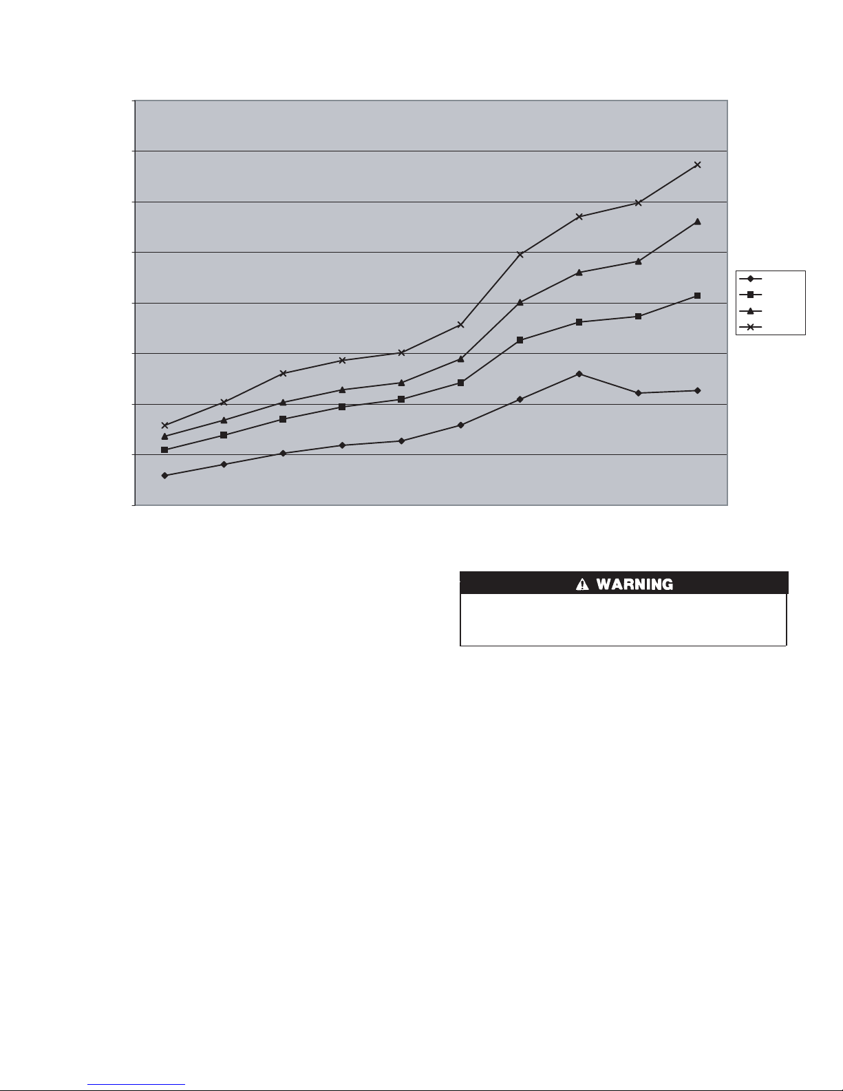
3. Inspect blower motor and wheel for cleanliness each cooling
season. Clean when necessary.
4. Check electrical connections for tightness and controls for
proper operation each cooling season. Service when necessary.
Step 1—Air Filter
IMPORTANT: Never operate the unit without a suitable air filter
in the return-air duct system. Always replace the filter with the
same dimensional size and type as originally installed. See Table
1 for recommended filter sizes.
Inspect air filter(s) at least once each month and replace
(throwaway-type) or clean (cleanable-type) at least twice during
each cooling season and twice during the heating season, or
whenever the filter becomes clogged with dust and lint.
Step 2—Indoor Blower and Motor
NOTE: All motors are prelubricated. Do not attempt to lubricate
these motors.
For longer life, operating economy, and continuing efficiency,
clean accumulated dirt and grease from the blower wheel and
motor annually.
Disconnect and tag electrical power to the unit before
cleaning and lubricating the blower motor and wheel. Failure
to adhere to this warning could cause personal injury or death.
Step 3—Outdoor Coil, Indoor Coil, and Condensate
Drain Pan
Inspect the condenser coil, evaporator coil, and condensate drain
pan at least once each year.
The coils are easily cleaned when dry; therefore, inspect and clean
the coils either before or after each cooling season. Remove all
obstructions, including weeds and shrubs, that interfere with the
airflow through the condenser coil.
Straighten bent fins with a fin comb. If coated with dirt or lint,
clean the coils with a vacuum cleaner, using the soft brush
attachment. Be careful not to bend the fins. If coated with oil or
grease, clean the coils with a mild detergent-and-water solution.
Rinse coils with clear water, using a garden hose. Be careful not to
splash water on motors, insulation, wiring, or air filter(s). For best
results, spray condenser coil fins from inside to outside the unit.
On units with an outer and inner condenser coil, be sure to clean
between the coils. Be sure to flush all dirt and debris from the unit
base.
Inspect the drain pan and condensate drain line when inspecting
the coils. Clean the drain pan and condensate drain by removing all
foreign matter from the pan. Flush the pan and drain trough with
clear water. Do not splash water on the insulation, motor, wiring,
or air filter(s). If the drain trough is restricted, clear it with a
“plumbers snake” or similar probe device.
Fig. 26—50XZ Balance Point Worksheet
C03008
Balance Point Worksheet
0
10
20
30
40
50
60
70
80
Outdoor Air Temp (Deg F)
Building Heat Loss (1000 BTUH)
Unit Integrated Heating Capacity (x1000 BTUH)
024
036
048
060
-10 0 10 17 20 30 40 47 50 60
Based on Entering Indoor Air of 70 Deg. F and Rated CFM
23
Page 24
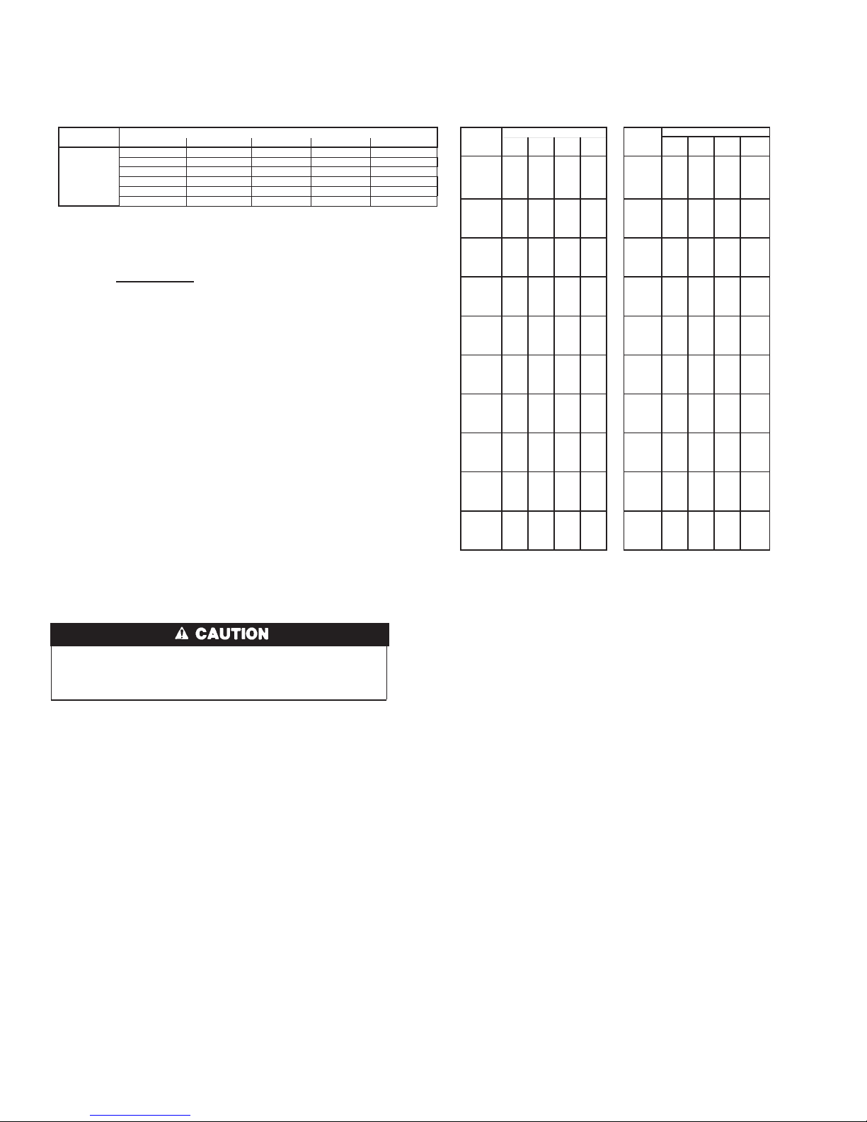
Step 4—Outdoor Fan
Keep the condenser fan free from all obstructions to ensure
proper cooling operation. Never place articles on top of the
unit. Damage to unit may result.
1. Remove 6 screws holding outdoor grille and motor to top
cover.
2. Turn motor/grille assembly upside down on top cover to
expose fan blade.
3. Inspect the fan blades for cracks or bends.
4. If fan needs to be removed, loosen setscrew and slide fan off
motor shaft.
5. When replacing fan blade, position blade so that the hub is 1/8
in. away from the motor end (1/8 in. of motor shaft will be
visible). (See Fig. 23)
6. Ensure that setscrew engages the flat area on the motor shaft
when tightening.
7. Replace grille.
Step 5—Electrical Controls and Wiring
Inspect and check the electrical controls and wiring annually. Be
sure to turn off the electrical power to the unit.
Remove access panel to locate all the electrical controls and
wiring. Check all electrical connections for tightness. Tighten all
screw connections. If any smoky or burned connections are
noticed, disassemble the connection, clean all the parts, restrip the
wire end and reassemble the connection properly and securely.
After inspecting the electrical controls and wiring, replace all the
panels. Start the unit, and observe at least one complete cooling
cycle to ensure proper operation. If discrepancies are observed in
operating cycle, or if a suspected malfunction has occurred, check
each electrical component with the proper electrical instrumentation. Refer to the unit wiring label when making these checkouts.
Step 6—Refrigerant Circuit
Inspect all refrigerant tubing connections and the unit base for oil
accumulation annually. Detecting oil generally indicates a refrigerant leak.
If oil is detected or if low performance is suspected, leak-test all
refrigerant tubing using an electronic leak detector, or liquid-soap
solution. If a refrigerant leak is detected, refer to Check for
Refrigerant Leaks section.
If no refrigerant leaks are found and low performance is suspected,
refer to Checking and Adjusting Refrigerant Charge section.
Step 7—Indoor Airflow
The heating and/or cooling airflow does not require checking
unless improper performance is suspected. If a problem exists, be
sure that all supply- and return-air grilles are open and free from
obstructions, and that the air filter is clean. When necessary, refer
to Indoor Airflow and Airflow Adjustments section to check the
system airflow.
Step 8—Metering Devices–TXV & Accurater Piston
This unit uses 2 types of metering devices. The outdoor metering
device is a fixed orifice and is contained in the brass hex-body in
the liquid line feeding the outdoor coils. The indoor metering
device is a TXV type device.
Fig. 27—Cooling Charging Table-Subcooling
C03027
(psig)
5 101520
(kPa)
36811
189 61 56 51 46 1303 13 13 11 8
203 66 61 56 51 1399 13 16 13 10
10.3 (5.7) 9.8 (5.4) 9.4 (5.2) 9 (5) 8.6 (4.7)
210 68 63 58 53 1448 13 17 14 11
NA NA NA NA NA
217 70 65 60 55 1496 13 18 15 13
17.6 (9.8) 16.8 (9.3) 16.5 (9.2) 15.4 (8.6) 14.3 (7.9)
224 72 67 62 57 1544 13 19 16 14
NA NA NA NA NA
231 74 69 64 59 1593 13 20 18 15
17.5 (9.7) 16.9 (9.4) 16.6 (9.2) 15.7 (8.7) 14.8 (8.2)
238 76 71 66 61 1641 13 21 19 16
13.7 (7.6) 13 (7.2) 13 (7.2) 14.5 (8.1) 11.5 (6.4)
245 77 72 67 62 1689 13 22 20 17
252 79 74 69 64 1737 13 23 21 18
260 81 76 71 66 1792 13 25 22 19
268 83 78 73 68 1848 13 26 23 20
276 85 80 75 70 1903 13 27 24 21
284 87 82 77 72 1958 13 28 25 22
292 89 84 79 74 2013 13 29 26 23
300 91 86 81 76 2068 13 30 27 24
309 93 88 83 78 2130 13 31 28 26
318 95 90 85 80 2192 13 32 29 27
327 97 92 87 82 2254 13 33 31 28
336 99 94 89 84 2316 13 34 32 29
345 101 96 91 86 2378 13 35 33 30
354 103 98 93 88 2440 13 36 34 31
364 105 100 95 90 2509 13 38 35 32
374 107 102 97 92 2578 13 39 36 33
384 108 103 98 93 2647 13 40 37 34
394 110 105 100 95 2716 13 41 38 35
404 112 107 102 97 2785 13 42 39 36
414 114 109 104 99 2854 13 43 40 37
424 116 111 106 101 2923 13 44 41 38
434 118 113 108 103 2992 13 45 42 39
444 119 114 109 104 3061 13 46 43 40
454 121 116 111 106 3130 13 47 44 41
464 123 118 113 108 3199 13 48 45 42
474 124 119 114 109 3268 13 48 46 43
484 126 121 116 111 3337 13 49 47 44
494 127 122 117 112 3406 13 50 47 45
504 129 124 119 114 3475 13 51 48 46
514 131 126 121 116 3544 13 52 49 46
524 132 127 122 117 3612 13 53 50 47
534 134 129 124 119 3681 13 54 51 48
Required Liquid Line Temperature for
Required Subcooling Deg F (Deg C)
Model Size
a Specific Subcooling (R-410A)
Charging Procedure
7- Read across from the Pressure reading to obtain the Liquid line temperature for a
required Subcooling
6- Find the Pressure Value in the table corresponding to the the measured Pressure of
the Compressor Discharge line.
5- Interpolate if the Outdoor ambient temperature lies in between the table values.
Extrapolate if the temperature lies beyond the table range.
1- Measure Discharge line pressure by attaching a gauge to the service port.
2- Measure the Liquid line temperature by attaching a temperature sensing device to it.
3- Insulate the temperature sensing device so that the Outdoor Ambient doesn’t affect
the reading.
4- Refer to the required Subcooling in the table based on the model size and the
Outdoor Ambient temperature.
8- Add Charge if the measured temperature is higher than the table value.
9- Add Charge using the service connection on the Suction line of the Compressor.
024
030
036
042
048
060
Outdoor Ambient Temperature
75 (24) 82 (28) 85 (29) 95 (35) 105 (41)
Pressure
Pressure
196
1351
Required Subcooling (Deg F) Required Subcooling (Deg C)
63 58
53 48 13
15 12
9
24
Page 25
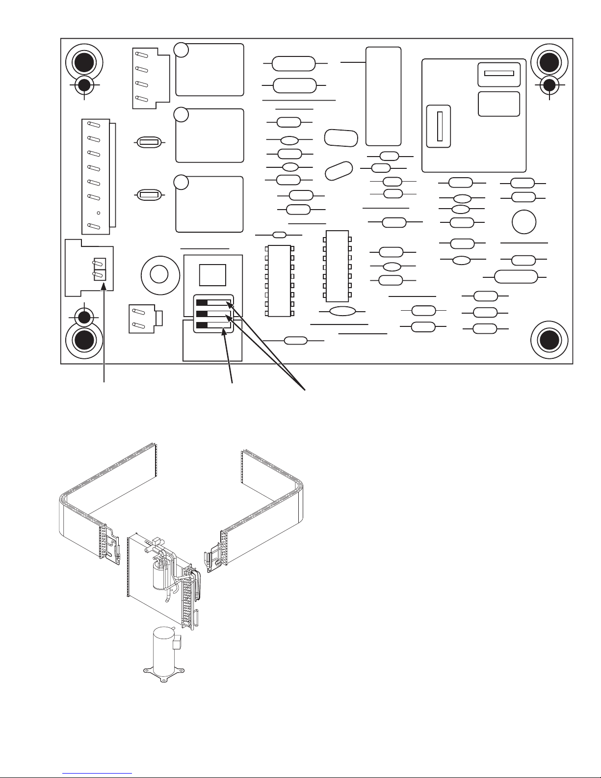
Step 9—Pressure Switches
Pressure switches are protective devices wired into control circuit
(low voltage). They shut off compressor if abnormally high or low
pressures are present in the refrigeration circuit. These pressure
switches are specifically designed to operate with Puron (R-410A)
systems. R-22 pressure switches must not be used as replacements
for the Puron (R-410A) system.
Step 10—Loss of Charge Switch
This switch is located on the liquid line and protects against low
suction pressures caused by such events as loss of charge, low
airflow across indoor coil, dirty filters, etc. It opens on a pressure
drop at about 20 psig. If system pressure is above this, switch
should be closed. To check switch:
1. Turn off all power to unit.
2. Disconnect leads on switch.
3. Apply ohm meter leads across switch. You should have
continuity on a good switch.
NOTE: Because these switches are attached to refrigeration
system under pressure, it is not advisable to remove this device for
troubleshooting unless you are reasonably certain that a problem
exists. If switch must be removed, remove and recover all system
charge so that pressure gauges read 0 psi. Never open system
without breaking vacuum with dry nitrogen.
Step 11—High-Pressure Switch
The high-pressure switch is located in the discharge line and
protects against excessive condenser coil pressure. It opens at 610
psig.
High pressure may be caused by a dirty outdoor coil, failed fan
motor, or outdoor air recirculation.
Fig. 28—Defrost Control
A99442
OF2
CESO130076–00
OF1
ON
QUIET
SHIFT
120
30
60
60
30
90
INTERVAL TIMER
OFF
P3
DFT
O R W
2
Y C
T2 C C O
DFT
T1 Y
P1
J1
SPEEDUP
Speedup
Pins
Defrost interval
DIP switches
Quiet
Shift
Fig. 29—Refrigerant Circuit
C99097
25
Page 26
To check switch:
1. Turn off all power to unit.
2. Disconnect leads on switch.
3. Apply ohm meter leads across switch. You should have
continuity on a good switch.
Step 12—Copeland Scroll Compressor (Puron Refrigerant)
The compressor used in this product is specifically designed to
operate with Puron (R-410A) refrigerant and cannot be interchanged.
The compressor is an electrical (as well as mechanical) device.
Exercise extreme caution when working near compressors. Power
should be shut off, if possible, for most troubleshooting techniques. Refrigerants present additional safety hazards.
Wear safety glasses and gloves when handling refrigerants.
Keep torches and other ignition sources away from refrigerants and oils. Failure to follow this warning can cause a fire,
serious injury, or death.
The scroll compressor pumps refrigerant throughout the system by
the interaction of a stationary and an orbiting scroll. The scroll
compressor has no dynamic suction or discharge valves, and it is
more tolerant of stresses caused by debris, liquid slugging, and
flooded starts. The compressor is equipped with an anti-rotational
device and an internal pressure relief port. The anti-rotational
device prevents the scroll from turning backwards and replaces the
need for a cycle protector. The pressure relief port is a safety
device, designed to protect against extreme high pressure. The
relief port has an operating range between 550 and 625 psi
differential pressure.
The Copeland scroll compressor uses Mobil 3MA POE oil.
This is the only oil allowed for oil recharge.
Step 13—Refrigerant System
This step covers the refrigerant system of the 50XZ, including the
compressor oil needed, servicing systems on roofs containing
synthetic materials, the filter drier and refrigerant charging.
REFRIGERANT
This system uses Puron (R-410A) refrigerant which has
higher operating pressures than R-22 and other refrigerants.
No other refrigerant may be used in this system. Gauge set,
hoses, and recovery system must be designed to handle
Puron. If you are unsure consult the equipment manufacturer.
Failure to use Puron compatible servicing equipment or
replacement components may result in property damage or
injury.
COMPRESSOR OIL
The compressor in this system uses a polyolester (POE) oil, Mobil
3MA POE. This oil is extremely hygroscopic, meaning it absorbs
water readily. POE oils can absorb 15 times as much water as other
oils designed for HCFC and CFC refrigerants. Take all necessary
precautions to avoid exposure of the oil to the atmosphere.
SERVICING SYSTEMS ON ROOFS WITH SYNTHETIC MATERIALS
POE (polyolester) compressor lubricants are known to cause long
term damage to some synthetic roofing materials.
Exposure, even if immediately cleaned up, may cause embrittlement (leading to cracking) to occur in one year or more. When
performing any service that may risk exposure of compressor oil to
the roof, take appropriate precautions to protect roofing. Procedures which risk oil leakage include, but are not limited to,
compressor replacement, repairing refrigerant leaks, replacing
refrigerant components such as filter drier, pressure switch, metering device, coil, accumulator, or reversing valve.
Synthetic Roof Precautionary Procedure
1. Cover extended roof working area with an impermeable
polyethylene (plastic) drip cloth or tarp. Cover an approximate
10 X 10 ft. area.
2. Cover area in front of the unit service panel with a terry cloth
shop towel to absorb lubricant spills and prevent run-offs, and
protect drop cloth from tears caused by tools or components.
3. Place terry cloth shop towel inside unit immediately under
component(s) to be serviced and prevent lubricant run-offs
through the louvered openings in the unit base.
4. Perform required service.
5. Remove and dispose of any oil contaminated material per
local codes.
LIQUID LINE FILTER DRIER
The biflow filter drier is specifically designed to operate with
Puron. Use only factory-authorized components. Filter drier must
be replaced whenever the refrigerant system is opened. When
removing a filter drier, use a tubing cutter to cut the drier from the
system. Do not unsweat a filter drier from the system. Heat
from unsweating will release moisture and contaminants from
drier into system.
PURON (R-410A) REFRIGERANT CHARGING
Refer to unit information plate and charging chart. Some R-410A
refrigerant cylinders contain a dip tube to allow liquid refrigerant to flow from cylinder in upright position. For cylinders
equipped with a dip tube, charge Puron units with cylinder in
upright position and a commercial metering device in manifold
hose. Charge refrigerant into suction-line.
Step 14—System Information
LOSS OF CHARGE SWITCH
The loss of charge switch is a protective device wired into control
circuit (low voltage). It shuts off the compressor if abnormally low
pressures are present in the refrigeration circuit.
NOTE: Because these switches are attached to refrigeration
system under pressure, it is not advisable to remove this device for
troubleshooting unless you are reasonably certain that a problem
exists. If switch must be removed, remove and recover all system
charge so that pressure gauges read 0 psi. Never open system
without breaking vacuum with dry nitrogen.
CHECK DEFROST THERMOSTAT
There is a liquid header with a brass distributor and feeder tube
going into outdoor coil. At the end of 1 of the feeder tubes, there
is a 3/8-in. OD stub tube approximately 3 in. long. (See Fig. 30)
The defrost thermostat should be located on stub tube. Note that
there is only 1 stub tube used with liquid header, and on most units
it is the bottom circuit.
The defrost thermostat signals heat pump that conditions are right
for defrost or that conditions have changed to terminate defrost. It
is a thermally actuated switch clamped to outdoor coil to sense its
temperature. Normal temperature range is closed at 30° ± 3°F and
open at 80° ± 5°F.
26
Page 27

NOTE: The defrost thermostat must be located on the liquid side
of the outdoor coil on the bottom circuit and as close to the coil as
possible.
TROUBLESHOOTING
Refer to the Cooling and Heating Troubleshooting Chart (Table 7)
for troubleshooting information.
START-UP CHECKLIST
Fig. 30—Defrost Thermostat
C99029
FEEDER TUBE
STUB TUBE
DEFROST
THERMOST AT
27
Page 28

HEAT PUMP WITH PURON
REFRIGERATION SECTION-QUICK REFERENCE GUIDE
Puron refrigerant operates at 50-70 percent higher pressures than R-22. Be sure that servicing equipment and replacement components are
designed to operate with Puron. Puron refrigerant cylinders are rose colored.
• Puron refrigerant cylinders manufactured prior to March 1, 1999, have a dip tube that allows liquid to flow out of cylinder in upright position.
Cylinders manufactured March 1, 1999 and later DO NOT have a dip tube and MUST be positioned upside down to allow liquid to flow.
• Recovery cylinder service pressure rating must be 400 psig. DOT 4BA400 or DOT BW400.
• Puron systems should be charged with liquid refrigerant. Use a commercial type metering device in the manifold hose.
• Manifold sets should be 750 psig high-side and 200 psig low-side with 520 psig low-side retard.
• Use hoses with 750 psig service pressure rating.
• Leak detectors should be designed to detect HFC refrigerant.
• Puron, as with other HFCs, is only compatible with POE oils.
• Vacuum pumps will not remove moisture from oil.
• Only use factory specified liquid-line filter driers with rated working pressures no less than 600 psig.
• Do not install a suction-line filter drier in liquid line.
• POE oils absorb moisture rapidly. Do not expose oil to atmosphere.
• POE oils may cause damage to certain plastics and roofing materials.
• Wrap all filter driers and service valves with wet cloth when brazing.
• A Puron liquid-line filter drier is required on every unit.
• Do not use an R-22 TXV.
• Never open system to atmosphere while it is under a vacuum.
• When system must be opened for service, break vacuum with dry nitrogen and replace filter driers.
• Do not vent Puron into the atmosphere.
• Observe all warnings, cautions, and bold text.
• Do not leave Puron suction line driers in place for more than 72 hrs.
28
Page 29
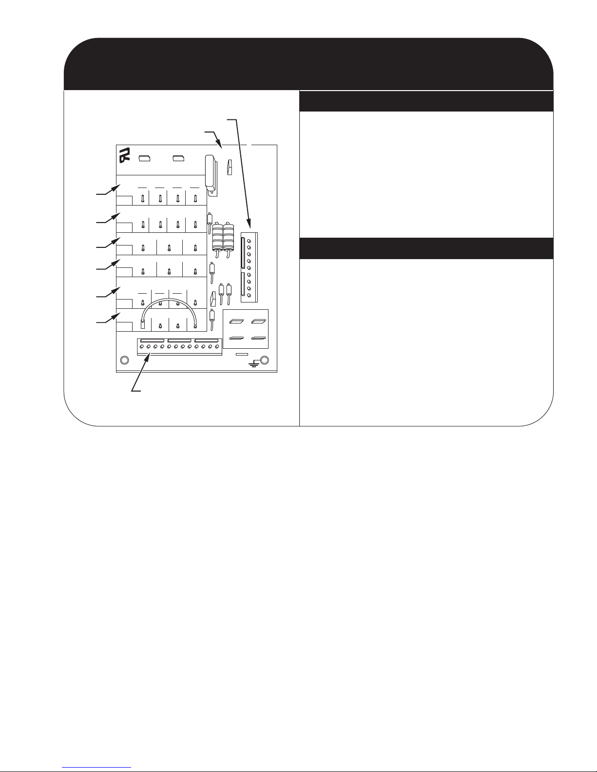
ECM ID BLOWER MOTOR-QUICK REFERENCE GUIDE
C01034
EASY SELECT
HEATER/MOTOR
AUX HEAT KW/CFM
0-30
1075
SEC1 SEC2
J1
AC/HP SIZE
036 030 024 018
AC
HP-COMFORT
HP-EFF
NOM HI
ENH
LO
SYSTEM TYPE
AC/HP CFM ADJUST
ON/OFF DELAY
CONTINUOUS FAN
MED HI YELLO
AUX1 HUM1
AUX2
24VAC
GRY
HUM2
YEL
WHT
BLK
ORN
BLU
VIO
0-20
875
0-10
725
09030900
0
0-5
625
TM
J2
D
H
R
W
1
W
2
Y
1
Y/Y
2
G
O
C
QUICK REFERENCE GUIDE
SET-UP INSTRUCTIONS FOR WARMER HEATING TEMPERATURES
AND SUPER HUMIDITY CONTROL IN COOLING
A. AUX HEAT - Set for heater size (Ex: 0-10 for 10 kw)
B. AC/HP SIZE - Set for size of outdoor unit
C. SYSTEM TYPE - Select "HP COMFORT"
D. AC/HP CFM ADJUST - Select "LO"
E. ON/OFF DELAY - Select "ENH"
F. CONTINUOUS FAN - Select desired speed
2. Remove Jumper J1 to activate all dehumidify modes.
3. Complete wiring and install outdoor temperature sensor
according to Installation Instructions.
1. Configuration Taps
(See Installation Instructions, for detailed description.)
• Option 5 (Variable Speed Motors) - set to ON
• Option 7 (Super Dehumidify) - set to ON
• Option 12 (Heaters during Defrost) - setting "2" is
suggested for all heaters
• Option 16 - Heat pump systems set to ON for warmer heat
below 40° F.
• Option 17 - Select programmable or non-programmable mode.
2. Thermidistat Control Configurations
(See Thermidistat™ Control Installation Instructions for
detailed description.)
3. Set desired humidity level on front of Thermidistat
(50 to 55% RH recommended). For dehumidification in
cooling, both "dhu" and "cool" must be displayed.
1. Set "DIP Switches" - Set the dip switches (back of Thermidistat
Control Board) appropriately for specific system being installed.
EASY SELECT BOARD
THERMIDISTAT™ CONTROL SETTINGS
9 PIN CONNECTOR
ICM PRINTED CIRCUIT BOARD
12 PIN CONNECTOR
A
B
C
D
E
F
29
Page 30
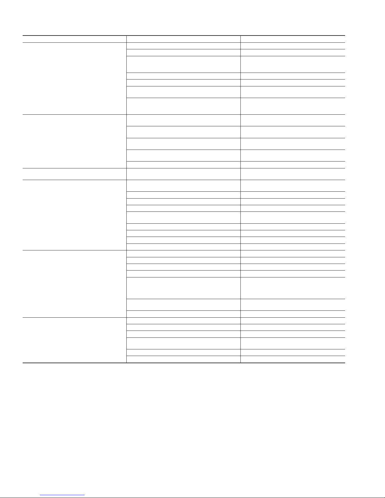
Table 7—Troubleshooting Chart
SYMPTOM CAUSE REMEDY
Compressor and outdoor fan
will not start
Power Failure Call power company
Fuse blown or circuit breaker tripped Replace fuse or reset circuit breaker
Defective thermostat, contactor, transformer,
control relay, defrost board, or high pressure or lossof-charge/low pressure switch
Replace component
Insufficient line voltage Determine cause and correct
Incorrect or faulty wiring Check wiring diagram and rewire correctly
Thermostat setting too high
Lower thermostat setting below room
temperature
Units have a 5-minute time delay
DO NOT bypass this compressor time
delay–wait for 5 minutes until time-delay
relay is deenergized
Compressor will not start but condenser fan
runs
Faulty wiring or loose connections in compressor
circuit
Check wiring and repair or replace
Compressor motor burned out, seized, or
internal overload open
Determine cause.
Replace compressor
Defective run capacitor, overload, or PTC
(positive temperature coefficient) thermistor
Determine cause and replace
One leg of 3-phase power dead
Replace fuse or reset circuit breaker. Determine
cause
Low input voltage (20 percent low) Determine cause and correct
Three-phase scroll compressor (size 030060 units) may be a low pressure differential
Scroll compressor is rotating in the wrong
direction
Correct the direction of rotation by reversing the
3-phase power leads to the unit
Compressor cycles (other than normally
satisfying thermostat)
Refrigerant overcharge or undercharge
Recover refrigerant, evacuate system, and
recharge to capacities shown on nameplate
Defective compressor Replace and determine cause
Insufficient line voltage Determine cause and correct
Blocked outdoor coil Determine cause and correct
Defective run/start capacitor, overload or start
relay
Determine cause and replace
Defective thermostat Replace thermostat
Faulty outdoor-fan motor or capacitor Replace
Damaged reversing valve Determine cause and correct
Restriction in refrigerant system Locate restriction and remove
Compressor operates continuously
Dirty air filter Replace filter
Unit undersized for load Decrease load or increase unit size
Thermostat set too low Reset thermostat
Low refrigerant charge Locate leak, repair, and recharge
Frosted coil with incorrect defrost operation
Check defrost time settings
Reset as necessary
Check defrost temperature switch
Replace as necessary
Air in system
Recover refrigerant, evacuate system,
and recharge
Outdoor coil dirty or restricted Clean coil or remove restriction
Excessive head pressure
Dirty air filter Replace filter
Dirty indoor or outdoor coil Clean coil
Refrigerant overcharged Recover excess refrigerant
Air in system
Recover refrigerant, evacuate system,
and recharge
(Heat) Indoor air restricted or recirculating Determine cause and correct
Indoor or outdoor air restricted or air short-cycling Determine cause and correct
(Continued next page)
30
Page 31
Table 7—Troubleshooting Chart (Cont’d)
SYMPTOM CAUSE REMEDY
Head pressure too low
Low refrigerant charge Check for leaks, repair and recharge
Restriction in liquid tube Remove restriction
Excessive suction pressure
(Heat) Outdoor coil frosted
Move timer on control board to 30 minutes
between defrost cycles
(Cool) High Heat load Check for source and eliminate
Reversing valve hung up or leaking internally Replace valve
Refrigerant overcharged Recover excess refrigerant
Suction pressure too low
(Cool) Dirty air filter Replace filter
(Heat) Outdoor coil frosted
Move timer on control board to 30 minutes
between defrost cycles
Low refrigerant charge Check for leaks, repair and recharge
Metering device or low side restricted Remove source of restriction
(Cool) Insufficient coil airflow
Increase air quantity
Check filter–replace if necessary
(Cool) Temperature too low in conditioned area Reset thermostat
(Cool) Outdoor ambient below 40°F Install low-ambient kit
Filter-drier restricted Replace
Compressor runs but outdoor fan does not
NC (normally closed) contacts on defrost board
open
Check condition of relay on board
Replace if necessary
IFM does not run
Blower wheel not secured to shaft Properly tighten blower wheel to shaft
Insufficient voltage at motor Determine cause and correct
Power connectors not properly sealed Connectors should snap easily; do not force
IFM operation is intermittent
Water dripping into motor Verify proper drip loops in connector wires
Connectors not firmly sealed
Gently pull wires individually to be sure they are
crimped into the housing
IFM–Indoor Fan Motor
31
Page 32
C01999
START-UP CHECKLIST
(Remove and Store in Job File)
I. Preliminar y Information
MODEL NO.:_________________________________
SERIAL NO.:__________________________________
DATE:_______________________________________
TECHNICIAN:_________________________________
II. PRE-START-UP (Insert checkmark in box as each item is completed)
( ) VERIFY THAT ALL PACKING MATERIALS HAVE BEEN REMOVED FROM UNIT
( ) REMOVE ALL SHIPPING HOLD DOWN BOLTS AND BRACKETS PER INSTALLATION INSTRUCTIONS
( ) CHECK ALL ELECTRICAL CONNECTIONS AND TERMINALS FOR TIGHTNESS
( ) CHECK GAS PIPING FOR LEAKS (WHERE APPLICABLE)
( ) CHECK THAT INDOOR (EVAPORATOR) AIR FILTER IS CLEAN AND IN PLACE
( ) VERIFY THAT UNIT INSTALLATION IS LEVEL
( ) CHECK FAN WHEEL, AND PROPELLER FOR LOCATION IN HOUSING/ORIFICE AND SETSCREW TIGHTNESS
( ) MAKE SURE THAT - ON 060 SIZE PURON HEATPUMP, ONLY-THE TWO WIRE TIES FASTEN TO THE
OUTDOOR COILS AND REVERSING VALVE/ACCUMULATOR HAVE BEEN REMOVED.
III. START-UP
ELECTRICAL
SUPPLY VOLTA GE __________________________________
COMPRESSOR AMPS_________________________________
INDOOR (EVAPORATOR) FAN AMPS___________
TEMPERATURES
OUTDOOR (CONDENSER) AIR TEMPERATURE ___________DB
RETURN-AIR TEMPERATURE ___________DB ___________WB
COOLING SUPPLY AIR ___________DB ___________WB
HEAT PUMP SUPPLY AIR ___________
GAS HEAT SUPPLY AIR ___________
ELECTRIC HEAT SUPPLY AIR ___________
PRESSURES
GAS INLET PRESSURE ___________IN.WG
GAS MANIFOLD PRESSURE ___________IN.WG
REFRIGERANT SUCTION ___________PSIG SUCTION LINE TEMP*___________
REFRIGERANT DISCHARGE ___________PSIG DISCHARGE TEMP†___________
( ) VERIFY REFRIGERANT CHARGE USING CHARGING CHARTS
GAS HEAT TEMPERATURE RISE
TEMPERATURE RISE (LITERATURE) RANGE___________
MEASURED TEMPERATURE RISE___________
*Measured at suction inlet to compressor
†Measured at liquid line leaving condenser.
IV. EASY SELECT SETTINGS
FULL UNIT MODEL NUMBER:___________
ENTER AVAILABLE HEATSETTINGS
ENTER AVAILABLE AIRFLOW HEAT AIR PIN CONNECTION
SETTING___________
ENTER AVAILABLE SIZES SIZE PIN CONNECTION SETTING___________
TYPE PIN CONNECTION SETTING___________
ADJUST PIN CONNECTION SETTING___________
DELAY PIN CONNECTION SETTING___________
(0/0 or 0/90 for gas/electric models)
CONTINOUS FAN PIN CONNECTION SETTING___________
EASY SELECT
Heat Settings
AC HP Size
System Type
AC HP-Comf ort HP.Eff
AC/HP CFM Adjust
Norm Lo Hi
On/Off Delay
0
⁄90
30
⁄90
0
⁄0 ENH
Continous Fan
Lo Med Hi
Manufacturer reserves the right to discontinue, or change at any time, specifications or designs without notice and without incurring obligations.
Book 1 4
Tab 5a 5a
PC101CatalogNo.535–00114 PrintedinU.S.A.Form50XZ-2SIPg 32 8–03Replaces:50XZ-1SI
 Loading...