

Carrier 50XJ064-104 User Manual
50BV020-064, 50XJ064-104
Remote Air-Cooled and Water-Cooled, VAV Systems
18 to 100 Nominal Tons
Controls Operation and
Troubleshooting
OMNIZONE™
Indoor Self-Contained
CONTENTS
SAFETY CONSIDERATIONS...................... 1
GENERAL ........................................1
MAJOR SYSTEM COMPONENTS ...............1-7
Comfort Controller Processor (PCB1) ............1
Comfort Controller I/O Module (PCB2)............2
Comfort Controller I/O Module (PCB3)............2
Local Interface Display ...........................2
PCB Addresses ..................................2
Control Module Communication.................. 2
Carrier Comfort Network Interface................4
Optional and Field-Installed
Accessory Sensors/Devices ...................4
Wiring Control Devices........................... 6
CONTROLS AND FUNCTIONS................. 8-15
Using the Local Interface Display ................ 8
Automatic Run Test ............................. 10
Power Up the LID Display .......................12
Log On to the LID Display ....................... 12
Change the Default Password ................... 12
Set the Clock.................................... 12
Configure Schedules............................13
Program Set Points ............................. 13
Check System Parameters ...................... 14
Display Alarm History ...........................14
Configure Custom Programming Selections .... 14
Set Controller Address ..........................15
Log Off from Controller ......................... 15
OPERATION.................................. 16-26
Occupancy Determination....................... 16
Fan Control .....................................16
Sequence of Operation..........................16
Diagnostic Features .............................18
50XJ Variable Frequency Drive Control..........19
50BV Variable Frequency Drive Control .........22
TROUBLESHOOTING......................... 27-29
Run Test Troubleshooting.......................27
Forcing and Clearing and Input or Output....... 27
Standard Diagnostic Features,
Alarm and Warning Lights .................... 28
APPENDIX A — WIRING DIAGRAMS ......... 30-42
APPENDIX B — CONTROL SCREENS ........ 43-64
Display Screens.................................43
Configuration Screens ..........................45
Maintenance Screens ........................... 58
SAFETY CONSIDERATIONS
Installing, starting up, and servicing this equipment can be
hazardous due to system pressures, electrical components, and
equipment location. Only trained, qualified installers and
service mechanics should install, start up, and service this
equipment.
When working on this equipment, observe precautions in
the literature; on tags, stickers, and labels attached to the equipment, and any other safety precautions that apply. Follow all
safety codes. Wear safety glasses and work gloves. Use care in
handling, rigging, and setting this equipment, and in handling
all electrical components.
Electrical shock can cause personal injury and death.
Shut off all power to this equipment during installation
and service. There may be more than one disconnect
switch. Tag all disconnect locations to alert others not to
restore power until work is completed.
This unit uses a microprocessor-based electronic control
system. Do not use jumpers or other tools to short out
components, or to bypass or otherwise depart from recommended procedures. Any short-to-ground of the control board or accompanying wiring may destroy the
electronic modules or electrical components.
GENERAL
This publication contains Start-Up, Controls Operation, and
Troubleshooting information for the 50BV,XJ units. These
OMNIZONE™ packaged units are self-contained, watercooled or remote air-cooled indoor units for use in VAV
(variable air volume) applications. Units are equipped with
Comfort Controller 6400 (CC6400) system controls. Refer to
the unit Installation Instructions for unit layout.
MAJOR SYSTEM COMPONENTS
Comfort Controller Processor (PCB1) —
The central processing unit for the OMNIZONE system
control is the Comfort Controller 6400. The Comfort Controller provides general purpose HVAC (heating, ventilation and
air conditioning) control and monitoring capability in a standalone or network environment using closed-loop, direct digital control. The Comfort Controller 6400 has been pre-programmed to work in either stand-alone or CCN (Carrier Comfort Network) system installations.
The CC6400 processor is designed to provide heating and
cooling control, loop control, scheduling, and custom programming. The main processor provides 16 field points (8 input and
8 output). Additional points are provided by the I/O modules
described on page 2. Table 1 lists the control inputs and outputs
for all CC6400 modules.
Specifications for the Comfort Controller 6400 may be
found in the Comfort Controller literature.
Manufacturer reserves the right to discontinue, or change at any time, specifications or designs without notice and without incurring obligations.
Book 1 1
Ta b 2 a 2 b
PC 111 Catalog No. 535-00137 Printed in U.S.A. Form 50BV,XJ-2T Pg 1 2-04 Replaces: 50BV,XJ-1T

Comfort Controller I/O Module (PCB2) — This
input/output module is factory installed in the 50XJ unit and
allows additional field points (8 inputs and 8 outputs): VFD
(variable frequency drive) Bypass, VAV Terminals Control,
Building Ventilation, and Heating Interlock.
Comfort Controller I/O Module (PCB3) — This
accessory control input/output module can be ordered separately and field-installed in the 50XJ unit. This module allows the
addition of the following field-installed sensors: Tower Sump
Temperature Sensor, Leaving Water Temperature Sensor,
Building Pressure Sensor, CO
Humidity Sensor, and Outdoor Temperature Sensor.
The accessory I/O module provides the following control
outputs (relays): 4-stage heat control, water pump request, tower
request, modulating exhaust fan, and external dehumidification.
Sensor, Indoor Relative
2
Local Interface Display — The Local Interface Display
(LID) is mounted on the front of the 50BV,XJ units. A number
of user-adjustable features are entered/changed using the
display keypad. These features described in detail in the Using
the Local Interface Display section of this manual.
PCB Addresses — Switch 1 (SW1) is used to set each
controller’s address. Individual DIP switches on each board are
used to set the addresses for individual hardware points. PCB1
switches are factory-set for hardware points 1-15, PCB2 DIP
switches are set for points 17-32, and PCB3 for points 33-48.
For more information, refer to Table 1 and the Optional and
Field-Installed Accessory Sensors/Devices section.
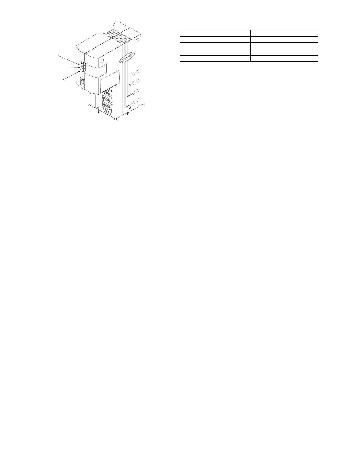
Control Module Communication — When power is
applied to the OMNIZONE™ System Control panel, the red
LED (light-emitting diode) on the top front of the processor
module will flash at a rapid pace (about twice a second) for the
first 30 to 60 seconds. See Fig. 1. This rapid flash will then be
replaced by a slower paced flash (about once per second).
The green LED below the red LED will start flashing. This
LED indicates input/output communications for accessory input
output modules and the LID.
The yellow LED (the third LED from the bottom of the controller [PCB1]) will flash when the controller is broadcasting
CCN messages to a laptop or other computer.
2
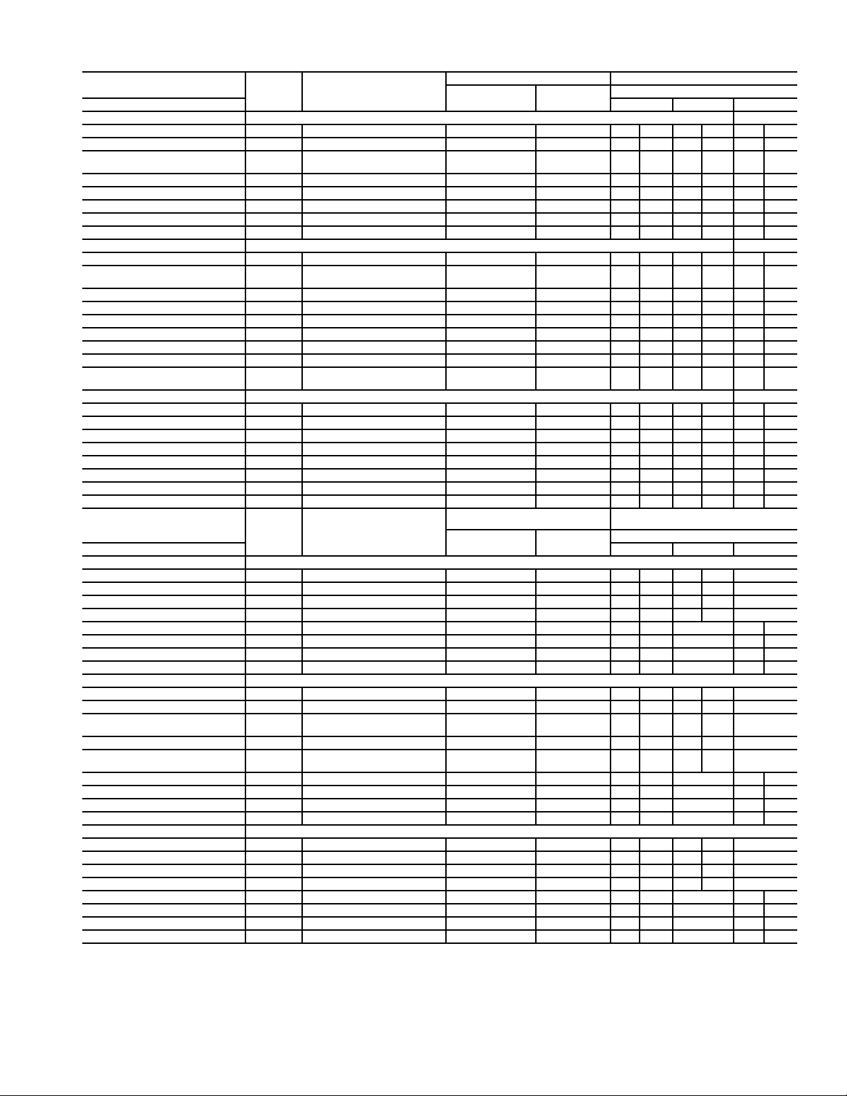
Table 1 — Control Inputs and Outputs
DESCRIPTION
Inputs SW2 SW3 SW1
Main Controller (PCB1) Addr = 1-16
Supply Air Temperature SAT Analog; 10K MCI 1 1 1 Up 1 Down 1 Up
VFD Duct Static Pressure DSP 4-20mA; Internally Powered 2 2 2 Up 2 Up 2 Down
COL/Safeties —
(Comprs.Status; Resister Bd.)
Fire Alarm/Shutdown FSD Switch closure 4 4 4 Up 4 Down 4 Down
Condenser Waterflow Switch CDWF Switch closure 5 5 5 Up 5 Down 5 Down
Remote Occupancy RMTOCC Switch closure 6 6 6 Up 6 Down 6 Down
Duct High Static Limit Switch DHS Switch closure 7 7 7 Up 7 Down 7 Up
Entering Water Temp. Sensor EWT Analog; 5K 8 8 8 Up 8 Down 8 Up
I/O Board (PCB2) Addr = 17-32
Mixed/Return Air Sensor MAT/RAT Analog; 10K MCI 1 1 1 Up 1 Down 1 Up
Filter Status Switch
(Dirty Filter Detect)
PhaseLossMonitor PHASE Switch closure 3 3 3 Up 3 Down 3 Down
External reset RESET 0-10VDC Externally Powered 4 4 4 Up 4 Down 4 Down
Water Econ. FreezeStat FREEZE Switch closure 5 — 5 Up 5 Down 5 Up
Differential Enthalpy ENTH Switch closure — 5 5 Up 5 Down 6 Down
Space Zone Sensor(s) SPT Analog; 10K MCI 6 6 6 Up 6 Down 7 Up
VFD Bypass Enable BYPASS Switch closure 7 7 7 Up 7 Down 8 Up
Refrigerant Pressure
(Compr.#1)
I/O Board (PCB3) Addr = 33-48
Tow e r S um p Te mp . TWRTEMP Analog; 10K MCI 1 1 1 Up 1 Up 1 Up
Building Pressure BSP 4-20mA; Internally Powered 2 2 2 Up 2 Down 2 Down
Leaving Water Temp. LWT Analog; 10K MCI 3 3 3 Up 3 Up 3 Down
Indoor Air Quality IAQ 4-20mA; Internally Powered — 4 4 Up 4 Down 4 Down
Indoor relative Humidity IRH 4-20mA; Internally Powered — 5 5 Up 5 Down 5 Down
Outside Air Temp. OAT Analog; 10K MCI — 6 6 Up 6 Up 6 Up
Unassigned —— ——————7Up
Unassigned —— ——————8Up
DESCRIPTION
Outputs SW4 SW5 SW6
Main Controller (PCB1)
Compressor #1 Relay CMP1 24VDC Discrete 1 1 1 Either 1 DO —
Compressor #2 Relay CMP2 24VDC Discrete 2 2 2 Either 2 DO —
Compressor #3 Relay CMP3 24VDC Discrete 3 3 3 Either 3 DO —
Compressor #4 Relay CMP4 24VDC Discrete 4 4 4 Either 4 DO —
VFD On/Off SF 24VDC Discrete 5 5 5 Either — 1 DO
VFD Speed Control SPEED 4-20mA modulating 6 6 6 Down — 2 AO
Alarm Pending ALARM1 24VDC Discrete 7 7 7 Either — 3 DO
Service Required ALARM2 24VDC Discrete 8 8 8 Either — 4 DO
I/O Board (PCB2)
Ventilation Output VENTOUT 24VDC Discrete 1 1 1 Either 1 DO —
Terminals Occupied OCCTRM 24VDC Discrete 2 2 2 Either 2 DO —
2-Position\
Reverse Operation Valve
Economizer Damper ECONO 4-20mA modulating — 3 3 Down 3 AO —
Modulating Valve Econ./
Head Pressure Control
Hot Water Coil Valve Control HWV 4-20mA modulating 5 5 5 Down — 1 AO
Heat Interlock Relay HIR 24VDC Discrete 6 6 6 Either — 2 DO
VFD Bypass Start BPSS 24VDC Discrete 7 7 7 Either — 3 DO
VAV Terminals Open DAMPERS 24VDC Discrete 8 8 8 Either — 4 DO
I/O Board (PCB3)
Electric Heat Control — Stage #1 HEAT1 24VDC Discrete 1 1 1 Either 1 DO —
Electric Heat Control — Stage #2 HEAT2 24VDC Discrete 2 2 2 Either 2 DO —
Electric Heat Control — Stage #3 HEAT3 24VDC Discrete 3 3 3 Either 3 DO —
Electric Heat Control — Stage #4 HEAT4 24VDC Discrete 4 4 4 Either 4 DO —
Water Pump Request PUMP 24VDC Discrete 5 5 5 Either — 1 DO
Tower Request TOWER 24VDC Discrete 6 6 6 Either — 2 DO
Modulating Exhaust Fan EXH 4-20mA modulating 7 7 7 Down — 3 AO
External Dehumidification DEHUM 24VDC Discrete 8 8 8 Either — 4 DO
LEGEND
AO — Analog Output
DO — Discreet Output
MCI — Precon Type II Thermistor
VAV — Variable Air Volume
VFD — Variable Frequency Drive
ABBREV. TYPE
CMP MUX Analog; 0-10VDC 3 3 3 Up 3 Down 3 Down
FLTS Switch closure 2 2 2 Up 2 Down 2 Down
PRES 4-20mA; Internally Powered 8 8 8 Up 8 Up — —
ABBREV. TYPE
ECONO 4-20mA modulating 3 3 Down 3 AO —
MODVLV 4-20mA modulating 4 4 4 Down 4 AO —
CONTROLLER I/O NO. DIP SWITCH SETTINGS
Water Econ. Units Air Econ.Units
CONTROLLER I/O NO. DIP SWITCH SETTINGS
Water Econ. Units Air Econ.Units
Switch No. and Position
Switch No. and Position
3
STATUS
RED
(POWER)
GREEN
(IO BUS
COMMUNICATIONS)
YELLOW
(CNN BUS
COMMUNICATIONS)
Fig. 1 — CC6400 Control Module LEDs
Carrier Comfort Network Interface — The 50BV,XJ
units can be connected to the CCN (Carrier Comfort Network)
if desired. System elements are connected to the communication bus in a daisy chain arrangement. The negative pin of
each system element’s communication connector must be
wired to the respective negative pins, and positive pins on each
component must be connected to respective positive pins. The
controller signal pins must be wired to the signal ground pins.
Wiring connections for CCN must be made at the 3-pin plug.
At any baud rate (9600, 19200, 38400 baud), the number of
controllers is limited to 239 devices maximum. Bus length may
not exceed 4000 ft, with no more than 60 total devices on
any 1000-ft section. Optically isolated RS-485 repeaters are
required every 1000 ft.
NOTE: Carrier device default is 9600 baud.
The CCN Communication Bus wiring is field-supplied and
field-installed. It consists of shielded three-conductor cable
with drain (ground) wire. The cable selected must be identical
to the CCN Communication Bus wire used for the entire
network. See Table 2 for cable recommendations.
NOTE: Conductors and drain wire must be at least 20 AWG
(American Wire Gage), stranded, and tinned copper.
Individual conductors must be insulated with PVC, PVC/
nylon, vinyl, Teflon, or polyethylene. An aluminum/
polyester 100% foil shield and an outer jacket of PVC,
PVC/nylon, chrome vinyl, or Teflon with a minimum
operating temperature range of –20 C to 60 C is required.
The communication bus shields must be tied together at
each system element. If the communication bus is entirely
within one building, the resulting continuous shield must be
connected to ground at only one single point. If the communication bus cable exits from one building and enters another
building, the shields must be connected to the grounds at a
lightning suppressor in each building (one point only).
Optional and Field-Installed Accessory Sensors/
Devices —
accessories that add functionality and control. These options
and accessories are controlled by the CC6400 system as
described below.
NOTE: The CC6400 Control software includes all PCB1
functions, and most of the sensors/devices associated with
those functions are factory installed. However, some PCB1
sensors/devices must be field-connected to the proper terminal.
PCB2 devices are field-installed accessories. The CC6400
software includes these functions, but the actual sensor/device
must be installed and wired in the field. PCB3 is an accessory
control module. All PCB3 sensors/devices and software are
field-installed.
The 50XJ unit can be ordered with options and
Table 2 — Communication Cable Recommendations
MANUFACTURER PART NUMBER
Alpha 2413 or 5463
American A22503
Belden 8772
Columbia 02525
REMOTE OCCUPANCY CONTROL (PCB1) — This control is a field located switch, controller or timer input which,
when activated, tells system when to switch from Unoccupied
to Occupied mode.
When in Occupied mode, the unit turns on the supply fan
and controls supply fan speed to maintain a duct static set point
measured at the Duct Static Pressure Sensor (DSP). The unit
operates to provide conditioning to a set point. When in
Unoccupied mode, the unit provides no cooling/heating, or
controls to a ‘setback’ set point.
FIRE ALARM (PCB1) — The fire alarm is a control voltage
input to the 50XJ unit, which causes the controller to shut the
system down in the event of a fire.
CONDENSER WATER FLOW SWITCH (50XJ
PCB1) — This thermal dispersion type flow switch if factory
installed, is located in the unit waterline to ensure that there is
waterflow before allowing the unit to start the compressor(s). If
no flow is detected, then compressor operation and economizer
cooling is avoided until waterflow is again detected. An
warning light (yellow) is provided during this state.
HEAT INTERLOCK OUTPUT (50XJ PCB2) — This output
is activated whenever heating is activated, commanding the
VAV dampers to operate in heating control mode.
NOTE: In order to this output to function, the Terminal
Occupied output must also be on.
TERMINAL OCCUPIED (50XJ PCB2) — Terminal Occupied is activated to command VAV dampers to control to the
cooling set point. Terminal Occupied must be on along with
Heat Interlock for heating set point control to function.
EXTERNAL RESET INPUT (50XJ PCB2) — This modulating input (0 to 10 vdc) allows remote adjustment (upward) of
the Supply Air Temperature (SAT) sensor set point. The default
External Reset Input setting is 55 F. This variable input can
raise the set point by up to 20 F for a full-range input signal, or
to any point in between.
WATER ECONOMIZER COIL (50XJ PCB2) — This factoryinstalled option contains a water-to-air coil, two (2) electronic
motorized water valves, and related piping. Control of the water
economizer also requires a Mixed/Return Air Temperature
Sensor, a Condenser Water Inlet Temperature Sensor and an
Economizer Freezestat safety switch.
The electronic motorized water valves are each controlled
by the unit controller via separate 4 to 20 mA variable signals
to define variable valve position.
The Mixed/Return Air Sensor (MA_RA) is an air
temperature sensor located in the unit, between economizer
coil and evaporator.
The Condenser Water Inlet Temperature Sensor (CWT) is
located at the unit water inlet connection. This sensor receives
input power from the unit main controller and provides a linear
variable 1 to 5 vdc signal back to the controller. The full
temperature range is 32 to120 F.
The 50XJ units can be connected to two types of building
water systems: variable and fixed or constant flow control. In
either case, the economizer water valves are opened whenever
there is a call for Cooling and the Inlet Water Temperature is
colder than the Econ Start Set Point in the custom configuration.
4

Dependencies
Fan is On, and Inlet Water Temperature is below set point; or
from “Remote Scheduler,” or from “Remote Linkage.”
Economizer mode is switched to Off or no start if: there is
no condenser waterflow, Fire Input is On, Fan is not On, or Unoccupied mode is On.
Variable Waterflow Systems
is off, the economizer flow control valve is fully closed, and the
reverse flow valve directly to the condenser is fully open. Upon
engagement of the water economizer, the economizer flow control valve shall be controlled to maintain the MA_RA located
between the economizer coil and the DX cooling coil, at a temperature near the supply air set point. The the reverse flow valve
will be controlled in reverse of the economizer flow control
valve’s position. The following formula is an example: Reverse/
Head Press Ctrl output = 100 – two-position/Econo output.
When the unit is off, both valves are closed.
Constant Waterflow Systems
flow control valve is same as for variable waterflow systems.
Control of the reverse flow control valve position will inversely
track the economizer flow control valve, such that the total sum
of the two valves open positions always equals 100%. The only
difference between the variable waterflow system and the
constant waterflow system is that for the constant flow system
when the unit is off, the economizer valve will be closed and
the reverse flow control valve will be open.
WATER ECONOMIZER COIL (50BV) — For the 50BV
unit, this factory-installed option contains a water-to-air coil, a
two-position diverting valve, and related piping. The water economizer is controlled by an Aquastat and a return-air thermostat.
HEATING COILS AND VALVE (50XJ PCB2) — Water or
steam heating options are factory installed. Each includes a
motorized, variable control water or steam flow control valve,
which can be factory supplied for field installation outside the
unit. Installed in the water or steam inlet pipe, this valve is
wiredtotheunitmaincontrollerandoperatesona4to20mA
signal. A Heating mode PID control is needed to control the
valve position (i.e., coil heating capacity) variably between 10
and 100%. The PID will control a set point to + 1° F; for VAV
Units this set point is at the Supply Air Temperature Sensor, or
as communicated from a remote thermostat.
HEAD PRESSURE CONTROL (50XJ PCB2) — Head Pressure Control is required for unit installations that will
experience entering condenser water temperatures of 55 F or
lower.
NOTE: Head Pressure Control is not needed or used in
conjunction with a Water Economizer. A refrigerant pressure transducer will monitor head pressure on compressor
circuit 1, allowing the unit main controller to regulate water
flow rate in the main water line entering the unit; i.e., flow
to all condensers. (Water header design to the condensers
will be optimized such as to provide relative flow rates to
each condenser based on its compressor capacity, enabling
successful waterflow control at the main entering pipe.)
There are two possible water valving configurations, as
outlined below.
Pressure transducer input is factory installed in the
discharge line of compressor circuit 1. It is provided 5 vdc by
the unit main controller and returns a signal 1 to 5 vdc linearly.
The sensor’s range is 0 to 550 psig.
Water Valve(s) Control
Variable Building Waterflow Systems — Variable waterflow
configurations use only one water valve in the main water
supply pipe. The factory installed valve is a normally open
motorized variable control type. The valve is controlled by a
4 to 20 mA signal from the main unit controller using the
Reverse/Head Press Ctrl output, which modulates to maintain
the head pressure set point (Setpoint 04).
— Water Economizer option is enabled, and
— Whenever water economizer
— Control of the economizer
Constant Building Waterflow Systems — Constant waterflow
configurations use two (2) water valves, only one of which is
in the main water supply pipe. The second valve is located in a
bypass pipe to the main outlet water pipe branched off of the
supply pipe immediately ahead of the first valve. This valve is
same type, but normally closed and is controlled in unison with
the first valve, but opposite position, such that the total opening
of the 2 valves always equals 100%.
VFD BYPASS (50XJ PCB2) — The VFD Bypass option
provides backup for the VFD Drive in VAV units. It uses a
manually operated rotary switch, which includes a series of
high voltage contacts. The bypass is a direct input to the unit
controller, and will be activated via a switch on the unit front
panel. When manually activated, the rotary switch takes the
VFD out of the fan power circuit and provides the 3-phase
power directly to the fan motor, running it at constant speed. A
low voltage control circuit ensures that the unit controller provides a signal to allow all VAV dampers to open fully before
the fan is turned on (at constant/full speed). A blue indicator
light located on the front of the unit indicates that the VFD Bypass is active. A High Duct Static Switch (HDS) shuts the fan
down if duct static exceeds a maximum setting.
VENTILATION OUTPUT (50XJ PCB2) — The ventilation
output is controller output signal (available for field connection)
to a field-supplied ventilation damper(s). This signal is activated
whenever the unit is in the occupied mode.
SPACE TEMPERATURE SENSOR (50XJ PCB2) — A fieldsupplied Carrier space temperature sensor is required to
maintain space temperature in sensor mode.
SUPPLY AIR RESET (50XJ PCB2) — Supply air temperature
set point may be reset using either the SPT or MA_RA.
SUPPLY AIR RESET (50BV) — Reset is provided by a
field-installed temperature sensor.
EXHAUST FAN CONTROL OUTPUT (50XJ PCB2) — This
output is activated whenever the unit is in the Occupied mode.
This is a modulating output that controls based on the Building
Pressure Input set point.
CONDENSER WATER PUMP/WATER TOWER (50XJ
PCB2) — This output (provided for field connection) is used
to control condenser water flow. Either an On/Off signal or a
variable output may be required for this feature.
PHASE LOSS/REVERSAL PROTECTION SWITCH
(50XJ PCB2) — This switch monitors VFD/Fan Motor supply leads to detect phase loss or reversal. If the switch detects
improper phasing, an input is sent to the unit controller, which
shuts the unit down. After a time delay, the controller attempts
to restart the unit.
A phase loss/reversal switch may be installed in the unit to
detect over/under voltage conditions and phase loss or reversal.
When the switch opens, the controller outputs are forced to off
with Safety forces, the alarm output will close and the red
alarm light will be lit. A system alarm will be generated and
displayed on the unit keypad. Unit reset is automatic when the
voltage and power phases have been restored.
FREEZE THERMOSTAT (FREEZSTAT) (50XJ PCB2) — The
Economizer Freezestat, used in conjunction with an optional
water economizer coil or heating coil, is a factory installed
averaging (capillary tube) air temperature sensor positioned in
the unit inlet airstream.
If the freeze protection switch contacts open the ventilation
request output will be closed for 15 minutes and the warning
light will light. If the freeze protection switch contacts are still
open after 15 minutes the supply fan will be stopped, all
compressor cooling will stop, the economizer valve will open
to 100%, the pump request output will remain on, and the
alarm light will light. This will maintain condenser water flow
through the coil to prevent freezing the coil while stopping all
other operations that could have contributed or will be affected
5
by the freeze condition. Unit reset is automatic when the
contacts on the freeze protection switch close again. The
contacts on the freeze protection switch open below 37 F.
TOWER SUMP TEMPERATURE SENSOR (50XJ
PCB3) — This sensor is used for monitoring (only) the tower
sump temperature.
LEAVING WATER TEMPERATURE SENSOR (50XJ
PCB3) — This sensor is used for monitoring (only) the leaving water temperature.
BUILDING STATIC PRESSURE SENSOR (50XJ
PCB3) — This sensor is used to control both the speed of the
building exhaust fan and the building static pressure.
INDOOR AIR QUALITY (CO
PCB3) — This sensor monitors CO
)SENSOR(50XJ
2
levels.
2
INDOOR RELATIVE HUMIDITY SENSOR (50XJ
PCB3) — This sensor monitors and controls the humidity
control relay.
OUTDOOR AIR TEMPERATURE SENSOR (50XJ
PCB3) — This sensor is used to monitor outdoor air and
broadcast the value over the Carrier Comfort Network (CCN).
STAGE HEAT RELAYS (50XJ PCB3) — These relays control up to four stages of electric heat, or other heating methods.
PUMP REQUEST RELAY (50XJ PCB3) — This relay turns
on a tower pump when requested.
TOWER REQUEST/CONTROL RELAY (50XJ PCB3) —
This relay is used to activate a tower fan.
BUILDING EXHAUST FAN SPEED CONTROL (50XJ
PCB3) — This output controls building exhaust fan speed.
HUMIDITY CONTROL RELAY (50XJ PCB3) — This relay
controls a humidifier or dehumidification device.
Wiring Control Devices — Standard controls for the
50XJ require no field-wiring. Standard 50XJ controls include:
Supply Air Temperature (SAT), Duct Static Pressure (DSP),
Duct High Static Limit Switch (DHS), Filter Status Switch
(FLTS), Entering Water Temperature (EWT), Compressor Status (CSMUX), Supply Fan Start/Stop (SF), Supply Fan Speed
(SPEED), and Mixed/Air Return/Air sensor (MA_RA).
NOTE: The MA_RA sensor will be located in the return air
steam if the unit does not have a water economizer, and in
the mixed airstream if the unit is equipped with a water
economizer.
For the 50BV unit, standard controls include: Duct Static
Pressure (DSP), Duct High Static Limit Switch (DHS), Compressor Status (CSMUX), Supply Fan Start/Stop (SF), and
Supply Fan Speed (SPEED).
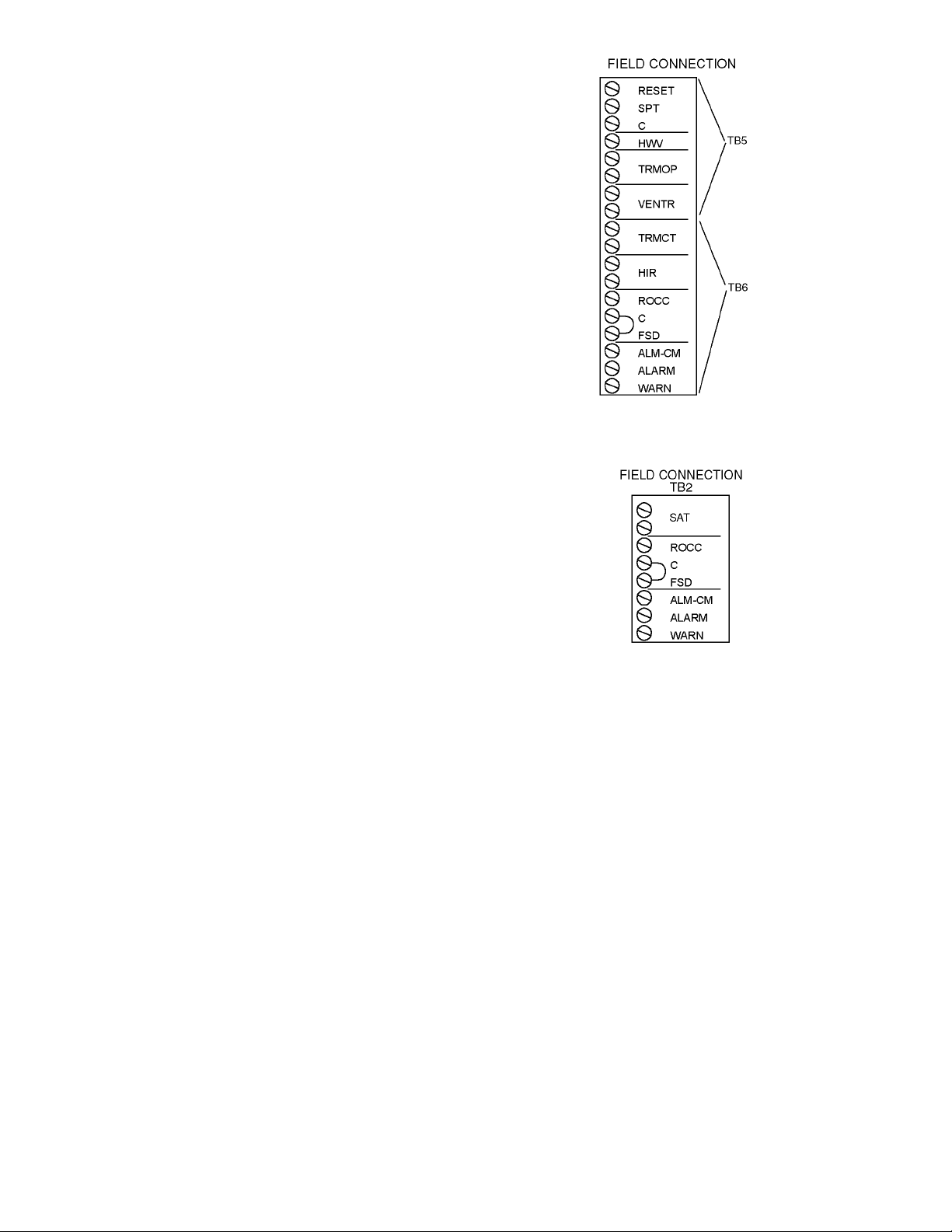
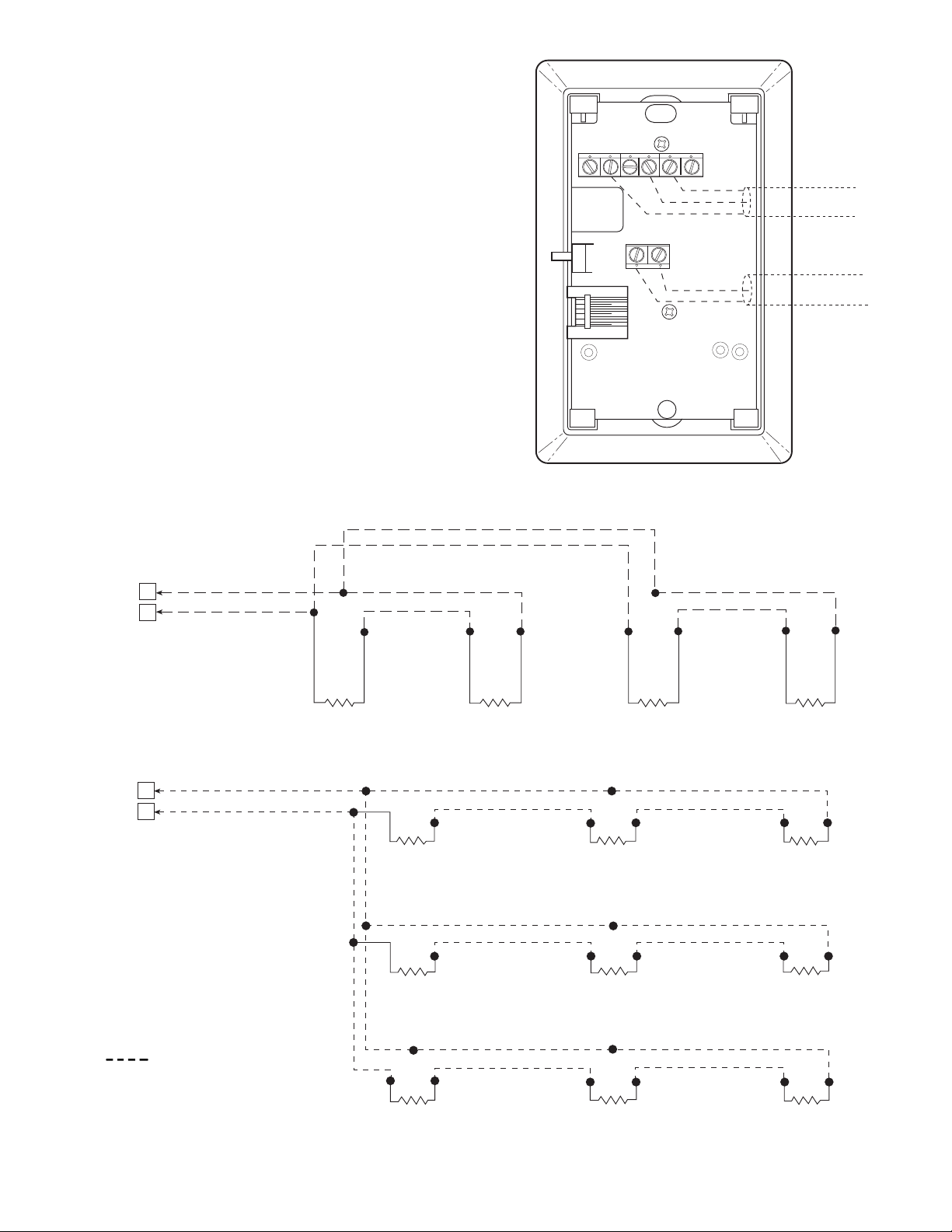
For the 50XJ unit, optional controls will be wired to the
field terminal blocks (TB5 and TB6) provided. Refer to
Fig. 2A and the descriptions below.
For the 50BV unit, optional controls are wired to field
terminal block TB2 as shown in Fig. 2B.
EXTERNAL 0 TO 10 VOLT DC RESET SIGNAL (RESET)
(50XJ PCB2) — This field-supplied 0 to 10 vdc signal is used
to reset the 50XJ supply-air temperature. The controller will
scale the signal to provide 0 reset at 0 volts and 20 degrees of
reset at 10 volts. Wire the positive of the signal to the RESET
terminal and the negative to the C or common terminal.
SUPPLY AIR RESET (50BV) — Use a 5k ohm sensor
installed at the Entering Water Temperature sensor (EWT)
location on PCB1. For space temperature averaging, two 10k
ohm Space Temperature Sensors (SPT) can be wired in parallel.
SPACE TEMPERATURE SENSOR (50XJ PCB2) — The
space temperature sensor (33ZCT55SPT) is used in the following cases:
• When using the optional water economizer and not using
Carrier’s ComfortID™ System.
Fig. 2A — Field Terminal Blocks for 50XJ Unit
Fig. 2B — Field Terminal Block for 50BV Unit
• To determine the average temperature of the space being
served.
• To determine supply-air temperature reset, occupied
heating, unoccupied heating and cooling (refer to
Sequence of Operation in the Start-Up section.).
To wire the sensor, perform the following (see Fig. 3).
Identify which cable is for the sensor wiring.
1. Strip back the jacket from the cable for at least
3 inches. Strip
1
/4-in. of insulation from each conductor. Cut the shield and drain wire from the sensor end
of the cable.
2. Wire the sensor to the SPT and C terminals on the field
terminal block (TB5). A typical 10K thermistor such
as the 33ZCT55SPT sensor may be used. If the SPT
sensor is not installed and the MA_RA (mixed air/
return air) sensor is configured for return air, the 50XJ
unit will use this sensor to control supply air reset,
occupied heat, and unoccupied heating and cooling
See Fig. 4 for space temperature sensor averaging.
HOT WATER OR STEAM VALVE (HWV) (50XJ
PCB2) — The HWV terminal supplies the positive signal to
control a 4 to 20 mA hot water or steam valve for occupied and
unoccupied heat. Connect the common side of the valve to the
C terminal or an equipment ground.
6
AIR TERMINALS AND FRESH AIR DAMPER (50XJ
PCB2) — The VAV Terminal Open (TRMOP), Ventilation
Output (VENTR), VAV Terminals Control (TRMCT), and
Heat Interlock Relay (HIR) terminals provide dry contacts to
command the VAV terminals open; a ventilation damper open;
VAV terminals to control to their cooling set points; and VAV
terminals to control to their heat set points, respectively.
REMOTE OCCUPANCY (ROCC) (TB2 50BV, TB6
50XJ) — The 50XJ,BV unit may be commanded by a remote
control system or a twist timer to become occupied and run
when a set of dry contacts close. In order for this to occur, wire
the contacts to ROCC and C.
SMOKE DETECTOR/FIRE ALARM SHUTDOWN (FSD)
(TB2 50BV, TB6 50XJ) — To allow a smoke detector to shut
the 50XJ,BV unit down, remove the jumper from FSD to C
and wire these terminals to a set of normally closed contacts on
the smoke detector.
ALARM (ALARM) AND WARNING (WARN) OUTPUTS
(TB2 50BV, TB6 50XJ) — Two dry contacts output a discrete signal when the alarm and warning lights on the display
are lit. To pick up the alarm output signal, wire between the
ALARM and ALM-CM terminals. To pick up the warning
output signal, wire between the WARN and ALM-CM
terminals.
45
61
RED(+)
WHT(GND)
BLK(-)
BRN (GND)
BLU (SPT)
CCN COM
SENSOR WIRING
SW1
2
3
SEN
Fig. 3 — Space Temperature Sensor
Typical Wiring (33ZCT55SPT)
RED
BLK
J6
6
7
RED
BLK
RED
BLK
SENSOR 1 SENSOR 2 SENSOR 3 SENSOR 4
RED
BLK
RED
BLK
SPACE TEMPERATURE AVERAGING — 4 SENSOR APPLICATION
J6
6
7
RED
BLK
BLK
SENSOR 1
RED
RED
BLK
RED
BLK
SENSOR 2
RED
BLK
SENSOR 3
RED
BLK
LEGEND
Field Wiring
BLK
SENSOR 4
RED
RED
BLK
SENSOR 7
SENSOR 5
SENSOR 8
SPACE TEMPERATURE AVERAGING — 9 SENSOR APPLICATION
Fig. 4 — Space Temperature Averaging
7
SENSOR 6
RED
BLK
SENSOR 9
CONTROLS AND FUNCTIONS
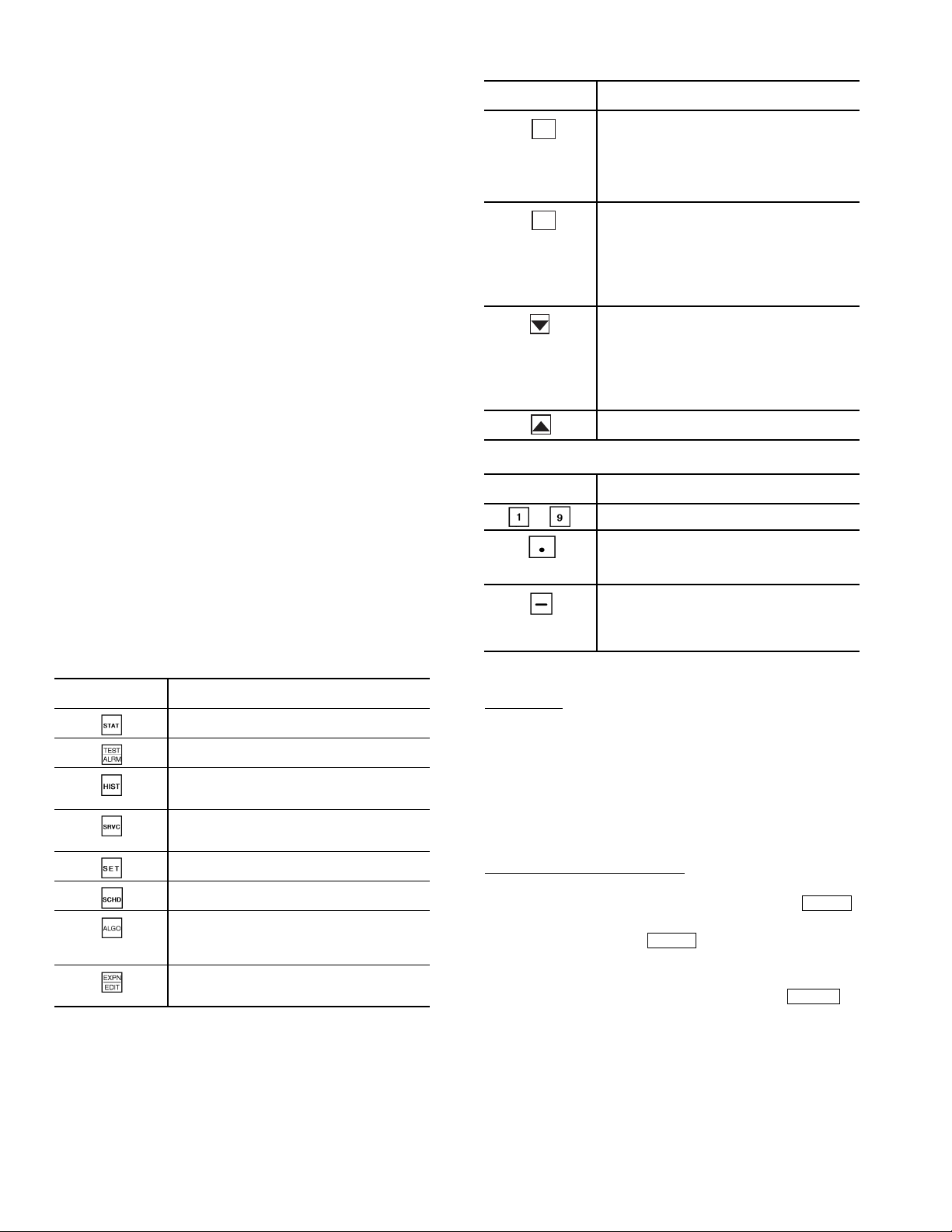
Table 4 — Operative Keys
Using the Local Interface Display —
The Local
Interface Device (LID) is a CCN operator interface that gives
the user the capability to view and modify all configuration and
service data for the CC6400 control system. The LID also
allows the user to override all point display and maintenance
data.
MENU STRUCTURE — The LID operates on a hierarchy of
four levels (menus).
The top level contains the LID’s major functions. Each
function has a corresponding key on the LID. For an explanation of each function key, refer to Table 3.
The second level separates the major functions (items) into
types with corresponding type numbers that can be used for
quick access.
The third level gives the user the capability to access each
occurrence of an item. For example, the application may
require two DO (Discreet Output) — Analog Comparison
algorithms. Thus, the CC6400 Controller would have two
occurrences of the DO — Analog Comparison algorithm.
The fourth level gives the user the capability to access maintenance and configuration data associated with the selected
occurrence of the item.
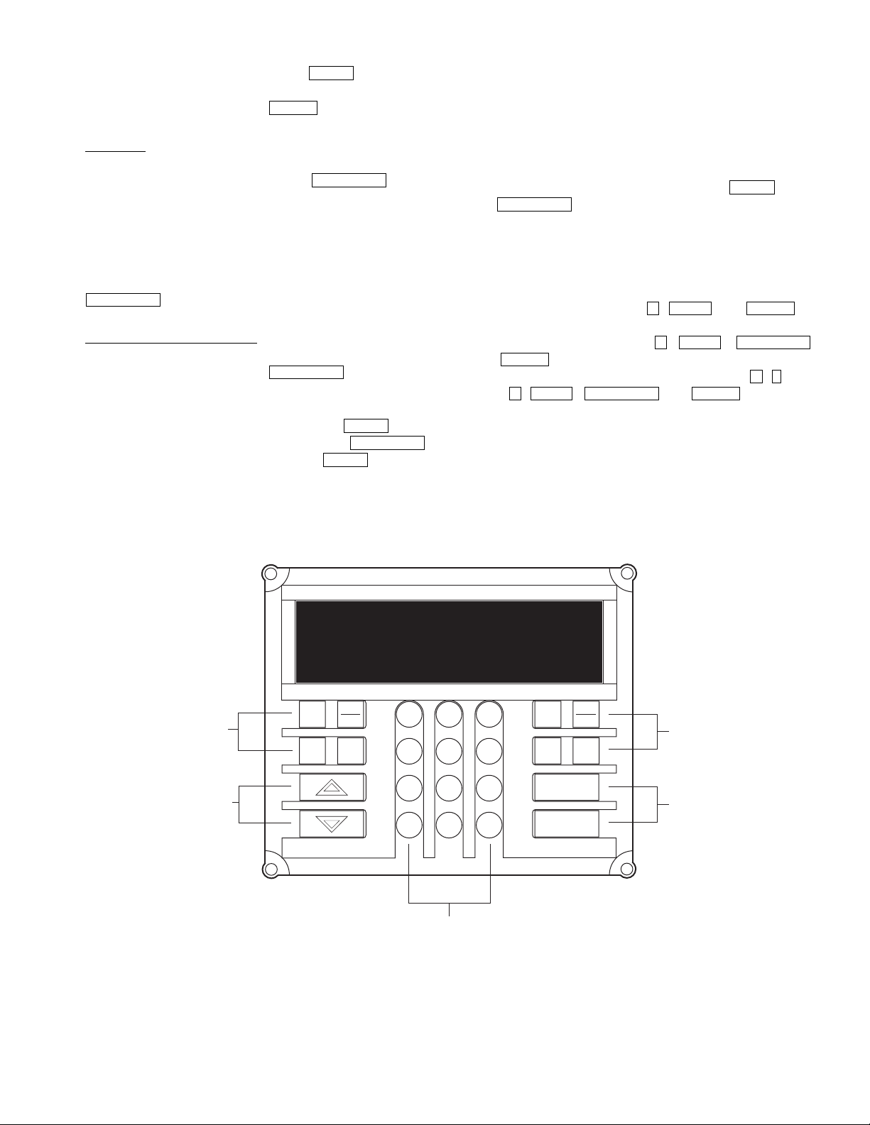
DEFAULT SCREEN — Figure 5 shows the LID. The LID’s
screen provides the user with the 24-character controller name
and the controller’s current time, date, and alarm status. This
screen appears when the LID is powered up and communicating with the controller or there is no keyboard activity for
10 minutes.
KEYPAD AND DISPLAY — The LID consists of a keypad
with 8 function keys, 4 operative keys, 12 numeric keys (0 to
9,., and -) and a two-line, alphanumeric liquid crystal display
(LCD). Each line on the LCD can display up to 24 characters.
See Fig. 5. Table 4 defines the purpose of the LID’s operative
keys. Table 5 defines the purpose of the LID’s numeric keys.
Table 3 — LID Function Keys
OPERATIVE
KEYS
Status — gives access to maintenance
values and configuration data for points.
Alarm — gives access to maintenance
and configuration data for alarms.
History — gives access to maintenance
and configuration data for history system
functions.
Service — gives access to maintenance
and configuration data for service system
functions.
Setup — gives access to configuration
data for setup system functions.
Schedule — gives access to maintenance
and configuration data for schedules.
Algorithm — gives access to maintenance
and configuration data for AO, DO, and global
algorithms. It also gives access to BEST
custom programs.
Edit — gives the capability to switch from
Status mode to Edit (configuration) mode for
the selected item.
LEGEND
AO — Analog Output
DO — Digital/Discreet Output
USE
++™
OPERATIVE
KEYS
CLEAR
ENTER
Clear — performs three operations:
• Cancels a data entry before the user
presses Enter, thus leaving the current
value unchanged.
• Returns a forced point to automatic
control.
• Redisplays the previous menu level.
Enter — performs two operations:
• Selects the displayed item, thus displaying
either its maintenance or configuration
data, depending on whether the user is in
the Status mode or the Edit mode.
• Accepts the value entered in a configuration
decision as new configuration data or as a
force.
Down arrow — displays the next configured
item or decision. When the last configured
item or decision is displayed, the LID
re-displays the first configured item or
decision. For example, when the user presses
the down arrow key while viewing the last
configuration decision of an algorithm, the LID
re-displays the first configuration decision.
Up arrow — Displays the previous configured
item or decision.
USE
Table 5 — Numeric Keys
OPERATIVE
KEYS
-
Numeric keys
Performs two operations:
• Separates items, such as an algorithm from
its occurrence or hours from minutes.
• Serves as a decimal point in numeric values.
Performs two operations:
• Negates the value of numeric keys.
• Clears current data entry value any time it is
not the first key pressed during the data
entry sequence.
USE
VIEWING MODES — The user can view items in either the
Status (maintenance) mode or the Edit (configuration) mode.
Status Mode
— When the user first powers up the LID, it
displays the CC6400 controller items in Status (maintenance)
mode. The user may view the current value or status of an item
in Status mode without actually logging on to the Controller.
Knowing the current values or status of items can be useful
when troubleshooting. For example, the user could determine
if a point was forced.
NOTE: Not all items have maintenance data. If the item you
select does not have maintenance data, the LID will display
“No maintenance.”
Accessing Items in Status Mode
— The user can access
maintenance data in Status mode in two ways:
• Pressing the appropriate function key (i.e., )
ALRM
once to access a category (i.e., alarms) and then continuing to press that key ( ) to scroll through all the
ALRM
items in that category (i.e., Limit Alarm, Set point
Alarm, Discrete Alarm, First Out Alarm, Runtime
Alarm, and Number of Starts Alarm). Press to
ENTER
display the first maintenance decision.
NOTE: Scrolling by repeatedly pressing the function key
displays the name of all the items in that category, whether
or not they are actually configured. Scrolling by pressing
the up or down arrow displays only the configured items
within that category.
8
• Pressing the appropriate LID numeric key (i.e., 2) and
the appropriate function key (i.e., ) to directly
ALRM
access an item without having to scroll through all the
items in that category. Press to display the first
ENTER
maintenance decision.
Edit Mode
— Because the LID first displays items in Status
mode when it is powered up, the user must log on to the connected CC6400 Controller and press the key to
EXPN/EDIT
switch to Edit mode.
While in Edit mode, the user can change the configuration
of items. For example, the user could change the value of an algorithm’s configuration decision.
NOTE: Not all items have configuration data. If the item
selected does not have configuration data, pressing the
EXPN/EDIT
key will have no effect. The LID will display
“No configuration.”
Accessing Items in Edit Mode
— The two ways to access
items in Edit mode are the same as in Status mode, except for
an additional step — pressing the key.
EXPN/EDIT
The user can access configuration data in Edit mode in two
ways:
• Pressing the appropriate function key (i.e., ) once
to access a category (i.e., alarms), pressing
and then continuing to press that key ( ) to scroll
ALRM
EXPN/EDIT
ALRM
through all the items in that category (i.e., Limit Alarm,
Set point Alarm, Discrete Alarm, First Out Alarm,
Runtime Alarm, and Number of Starts Alarm).
NOTE: Scrolling by repeatedly pressing the function key
displays the name of all the items in that category, whether
or not they are actually configured. Scrolling by pressing
the up or down arrow displays only the configured items
within that category.
• Pressing the appropriate LID numeric key (i.e., 2),
the appropriate function key (i.e., ), and
EXPN/EDIT
to directly access an item without having
ALRM
to scroll through all the items in that category.
QUICK ACCESS IN EITHER STATUS OR EDIT
MODE — Use Table 6 as a reference to directly access
CC6400 Controller items using a LID in either Status or Edit
mods. For example, to access maintenance data for the AO —
Heating VAV algorithm, press , , and . To
6 ALGO ENTER
access configuration data for the AO (Analog Output) —
Heating VAV algorithm, press , , ,
and . If the database consisted of two AO — Heating
ENTER
VAV algorithms, to access the second one, press , (decimal), ,, ,and .
2 ALGO EXPN/EDIT ENTER
6 ALGO EXPN/EDIT
6 .
FUNCTION
KEYS
OPERATIVE
KEYS
OMNIZONE VPAC
12:00 02-06-04
EXPN
STAT
SET
EDIT
SCHD
1
4
7
–
NUMERIC KEYS
Fig. 5 — Local Interface Display (LID)
3
2
5
6
8
9
.
0
TEST
SRVC
ALRM
HIST ALGO
CLEAR
ENTER
FUNCTION
KEYS
OPERATIVE
KEYS
9
Table 6 — Quick Access Chart
LID
NUM.
KEY
1 AO—Adaptive Control Hardware Points Alarm History Function Definition Limit Set Clock Occupancy
2 AO—Cooling CV Software Points Analog Point Trace Channel Definition Setpoint Real Time Clock Setpoint
3 AO—Cooling VAV Temperature Input Discrete Point Trace System Definition Discrete Controller Password Holiday
4 AO—Fan Tracking Milliamp Input Consumable Channel Setpoint Definition First out N/A S/W Setpoint
5 AO—Heating CV Custom Milliamp Input Internal Consumable Database Control Runtime N/A Network Time
6 AO—Heating VAV Voltage Input Runtime Channel Comfort Controller # of starts N/A N/A
7 AO—Humidity Control Custom Voltage Input N/A CCN Control N/A N/A N/A
8 AO—Mixed Air CV w/IAQ Sensed Discrete Input N/A LID Preferences N/A N/A N/A
9 AO—Mixed Air VAV w/IAQ Latched Discrete Input N/A N/A N/A N/A N/A
10 AO—Permissive Interlock Pulsed Discrete Input N/A N/A N/A N/A N/A
11 AO—Reset Milliamp Output N/A N/A N/A N/A N/A
12 AO—Shared Transducer Custom Milliamp Output N/A N/A N/A N/A N/A
13 AO—Static Pressure Voltage Output N/A N/A N/A N/A N/A
14 DO—Analog Custom Voltage Output N/A N/A N/A N/A N/A
15 DO—DX-Staging VAV Discrete Output N/A N/A N/A N/A N/A
16 DO—Electric Heat CV Stepper Motor Output N/A N/A N/A N/A N/A
17 DO—Electric Heat VAV Discrete Software Point N/A N/A N/A N/A N/A
18 DO—Enthalpy Comparison Analog Software Point N/A N/A N/A N/A N/A
19 DO—Interlock Network Data Out N/A N/A N/A N/A N/A
20 DO—Lighting Control Network Data In N/A N/A N/A N/A N/A
21 DO—Permissive Interlock N/A N/A N/A N/A N/A N/A
22 DO—Pump Control N/A N/A N/A N/A N/A N/A
23 DO—Prop Ther mo N/A N/A N/A N/A N/A N/A
24 DO—Prop Thermo 2 Pipe N/A N/A N/A N/A N/A N/A
25 DO—Prop Thermo 4 Pipe N/A N/A N/A N/A N/A N/A
26 DO—Staged Thermostat N/A N/A N/A N/A N/A N/A
27 DO—Staging Control N/A N/A N/A N/A N/A N/A
28 DO—Time Clock N/A N/A N/A N/A N/A N/A
29 DO—Time Clock w/Check N/A N/A N/A N/A N/A N/A
30 AOSS Schedule N/A N/A N/A N/A N/A N/A
31 Network Broadcast N/A N/A N/A N/A N/A N/A
32 Linkage/AOSS Schedule N/A N/A N/A N/A N/A N/A
33 NTFC w/Enthalpy Check N/A N/A N/A N/A N/A N/A
34 Sensor Group N/A N/A N/A N/A N/A N/A
35 WSM Air Source N/A N/A N/A N/A N/A N/A
36 WSM Cool Source N/A N/A N/A N/A N/A N/A
37 Custom Program N/A N/A N/A N/A N/A N/A
AO — Analog Output
AOS S — Adaptive Optimal Star t/Stop
CV — Constant Volume
DO — Digital Output
IAQ — Indoor Air Quality
N/A — Not Available
NTFC — Nighttime Free Cooling
VAV — Variable Air Volume
WSM — Water System Manager
Algorithms
(ALGO)
LEGEND NOTES:
Status
(STAT)
LID FUNCTION KEYS
History
(HIST)
1. To change from Edit mode to Status mode, press or press
EXPN/EDIT
2. Not all available selections will have items to select in sublevels.
Service
(SRVC)
again.
Alarm
(ALRM)
Setup
(SET)
Schedules
CLEAR
(SCHD)
Automatic Run Test — The 50BV,XJ unit controls are
programmed with an automatic run test that checks connection
and operation of major components. To perform the run test:
Verify that the control display (LID device/System Monitor)
interface cable is connected to internal jack on main controller;
that the fire alarm/shutdown switch input (FSD) has a factory
jumper or field input; that Bypass (if installed) is set in the
DRIVE position; and that the Local/Off/Remote switch is set to
the REMOTE position.
NOTE: When the Local/Off/Remote switch is in the
REMOTE position, the controller time schedule is pre-set
(from the factory) as unoccupied. This means that the unit
will not turn on until the run test is enabled. However, if the
controller schedule has already been modified in the field,
and the current time of day is occupied, then the supply fan
will start. The run test will shut the fan down when it
begins. The run test will complete and then the supply will
automatically restart.
NOTE: If the Local/Off/Remote switch is in the OFF position, it is normal for the red alarm light on the display panel
to be lit, indicating that the unit is disabled.
NOTE: If the red light stays on when the switch is moved to
REMOTE, or if any other problems occur during the run
test, refer to the Troubleshooting section of this manual.
To perform the Run Test:
1. Turn unit power on.
The LID display will show the controller identification, time and date (Fig. 5):
OMNIZONE VPAC
hh:mm mm-dd-yy
10
2. Press 3 and then . The LID display will show:
Controller Password
3. Press . The LID display will show:
4. Key in the password and press .
5. The LID display will show:
6. Press . The LID display will show:
7. Press again. The LID display will show:
8. Press . The LID display will show:
9. Press 6 times. The LID display will show:
10. Press 1 then , The LID display will show:
11. The control module will now check if there is input from
ENTER
LogintoController
Enter Password
NOTE: The LID display has two modes: Edit mode and
Status/Maintenance mode. If the LID display is in Edit
mode, then the display will only show the word “password.” Press the key to toggle to the Status
mode.
Press the to display:
LogintoController
Enter Password
NOTE: The default password is 1111.
LogintoController
Logged In
NOTE: At this point, for the 50BV unit only, the run
test will follow these steps:
a. Press 37 . The display will show:
Custom Program
b. Press . The display will show:
2.0 Global Dictionary
OMNIZONE
c. Press (NOTE: Display will flash,
indicating that the device is now in edit mode.)
The display will show:
2.0 Global Dictionary
OMNIZONE
d. Press . The display will show:
Compressor Stages
4.00
NOTE: A 50BV unit with only 2 compressors will
display 2.00. Skip to Step 6.
e. Input 2.00 and Press . The display will show:
Compressor Stages
2.00
STAT
Hardware Points
STAT
Software Points
ENTER
Compressor 1 Status
Factory/Field Test
Stop
Factory/Field Test
Start
NOTE: At this point, the yellow warning light on the
display panel will be lit and will stay on throughout the
run test. After each successful step, the red alarm light
will blink once.
BYPAS(50XJ),DHS,FSD,SAT,DSP,andCSMUX.
SET
EXPN/EDIT
EXPN/EDIT
ENTER
ALGO
ENTER
EXPN/EDIT
ENTER
ENTER
ENTER
If the control does not receive open/open/closed/
in range/in range/in range, the red alarm LED will go
on and the test will stop.
If the inputs are OK, the red alarm LED blinks once
and the test continues.
12. Next, the control forces the Supply Fan (SF) and all of the
Compressors (COMP) off, and waits 15 seconds.
For the 50XJ unit, if the REMOTE LED and AUTO
LED on the VFD display are on, the red LED blinks
once and the test continues.
NOTE: For the 50XJ unit, if the controller is configured with a water Economizer, the delay is 2 min. and
both valves are commanded to 0%. Both water valves
will close.
13. The control forces SF on and SPEED to 20 percent and
then waits 30 seconds.
If the VFD display shows “10.6 Hz,” the Remote and
Auto LEDs blink, and the fan goes on, then the red LED
on the control module blinks once and the test continues.
NOTE: For the 50XJ unit, if the controller is configured with a water Economizer the delay is 2 min. and
Econo valve is commanded to 100%. The economizer
valve will open and the RVS/HD (reverse/head
pressure) valve will remain closed.
14. The control forces SF on and SPEED to 35 percent and
then waits 30 seconds.
If the VFD display shows “20.0 Hz,” the Remote and
Auto LEDs blink, and the fan goes on, then the red LED
on the control module blinks once and the test continues.
NOTE: For the 50XJ unit, if the controller is configured
with a water Economizer the delay is 2 min. and RVS/
HD valve is commanded to 100%. The economizer valve
is commanded to 0% and the RVS/HD valve will open.
15. The control forces SF off then waits 15 seconds.
If the VFD display shows “Off,” the Remote and Auto
LEDs are off, and the fan goes off, then the red LED on
the control module blinks once and the test continues.
NOTE: For the 50XJ unit, if the controller is configured
with a water Economizer both valves are commanded
to 0%. The economizer valve and RVS/HD will close.
NOTE: For the 50BV unit, the steps below (16-24)
will be completed for the number of compressors
configured.
16. The control forces CMP1 (compressor 1) on then waits
5 seconds.
If CSMUX is not in range the red LED will go on and
the test will stop.
If CSMUX is in range, the red LED blinks once and
the test continues.
17. The control forces CMP1 off.
18. The control forces CMP2 (compressor 2) on then waits
5 seconds.
If CSMUX is not in range the red LED will go on and
the test will stop.
If CSMUX is in range, the red LED blinks once and
the test continues.
19. The control forces CMP2 off.
20. The control forces CMP3 (compressor 3) on, if configured, then waits 5 seconds.
If CSMUX is not in range the red LED will go on and
the test will stop.
If CSMUX is in range, the red LED blinks once and
the test continues.
21. The control forces CMP3 off.
11
22. The control forces CMP4 (compressor 4) on, if configured, then waits 5 seconds.
The LID display shows:
Factory/Field Test
Stop
The yellow LED will go off, and the red LED will go
off.
23. The control forces CMP4 off.
24. The run test is complete.
Power Up the LID Display — After completing the
automatic run test, perform the following procedures to change
the controller password, set the controller clock, configure
schedules, set parameters, view settings, and view alarm
history.
1. Set the Remote/Local/Off switch on the front of the unit to
the OFF position. This prevents operation of the fan and
compressors while still providing power to the unit controls.
NOTE: When the switch is in the OFF position, the red
alarm LED will be lit; this is normal. The bypass point
will also indicate OK.
2. If the unit access panel (for power and controls) is still on
the unit, remove it in order to view the control modules
during start-up.
3. Switch the main unit power disconnect to ON.
When power is applied to the OMNIZONE™ System
Control panel, the red LED on the top front of the processor
module will flash at a rapid pace (about twice a second) for the
first 30 to 60 seconds. This rapid flash will then be replaced by
a slower paced flash (about once per second).
The green LED below the red LED will start flashing. This
LED indicates input/output communications for accessory
input output modules and the LID display.
The yellow LED will flash when the controller is broadcasting CCN messages to a laptop or other computer.
The third LED from the bottom of the controller (PCB1)
will light.
The LID display will show the controller identification,
time and date as shown below.
OMNIZONE VPAC
hh:mm mm-dd-yy
Log On to the LID Display — ToLogOntotheLID
display, perform the following procedure:
1. Press 3 and then . The LID display will show:
Controller Password
2. Press . The LID display will show:
3. Key in the password and press .
ENTER
LogintoController
Enter Password
NOTE: The LID display has two modes: Edit mode and
Status/Maintenance mode. Edit mode allows the user to
change settings on the configurations screens. Status/
Maintenance mode only allows the user to look at the
settings.
If the LID display is in Edit mode, then the display will
only show the word “password.” Press the
EXPN/EDIT
sure the LID display shows:
LogintoController
Enter Password
NOTE: The default password is 1111.
SET
key to toggle to the Status mode. Make
ENTER
4. The LID display will show:
LogintoController
Logged In
NOTE: The user will be automatically logged off after
15 min. of non-use.
Change the Default Password — To change the
default password, perform the following procedure:
NOTE: The password must have already been entered to
perform this procedure.
1. Press 3 and then . The LID display will show:
Controller Password
2. Press . The LID display will show:
3. Press . The LID display will show:
4. Enter the new password (up to 6 digits) and press
5. Press twice to leave the password screen and re-
ENTER
LogintoController
Logged in
EXPN/EDIT
Password
1111 (default password, or previous password entered)
ENTER
Password
(password just entered)
NOTE: Remember this password; write it down.
CLEAR
turn to the default display screen.
SET
. The LID display will show:
Set the Clock — The user must be logged in to set the
clock. To set the clock, perform the following procedure:
1. Press 1 and then . The LID display will show:
Set Clock
2. Press . The LID display will show:
3. Press . The LID display will show:
4. Enter the time. The time is entered in military time (for
5. Enter the day of week. The numbers 1 through 7 corre-
6. Enter the number of the corresponding month (1 through
7. Enter the day of the month. Press then press
ENTER
No Maintenance
NOTE: There is no maintenance information regarding
setting the clock.
EXPN/EDIT
Time
00:00
example 14.59 for 2.59 pm). Press then press
the button. The LID display will show:
Day of Week
1
spond to the days of the week (1 = MON, 2 = TUE,
3 = WED, 4 = THUR, 5 = FRI, 6 = SAT, 7 = SUN). Press
ENTER
Month
1
12). Press then press . The LID display
will show:
Day
1
. The LID display will show:
Ye a r
95
SET
ENTER
then press . The LID display will show:
ENTER
ENTER
12
8. Enter the last two digits of the current year. Press
ENTER
Update Clock
No
9. Press 1 and then to cause the controller to
update the clock. The LID display will flash. Press
CLEAR
should update to the input time and date.
then press . The LID display will show:
ENTER
twice to view the default display and the clock
Configure Schedules — Schedules are one method of
starting and stopping the unit at specified intervals. To configure the schedules, perform the following procedure:
1. Press 1 and then . The LID display will show:
Occupancy Algorithm
2. Press . The LID display will show:
3. Press . If the LID display shows “MODE 0” then
4. Press . The LID display will show:
5. Press the button. The LID display will show:
6. Input the Occupancy Start time for this period.
7. Press the to input the Occupied To time for period 1.
8. Input the days and times for periods 2 through 8 as
9. Press clear to leave the occupancy programming.
ENTER
Time Schedule
Enter to select
ENTER
the user is in Maintenance mode and the LID display is
showing the maintenance information for the occupancy
schedule. Press to enter the configuration
mode. The LID display will show:
Manual Override Hours
0 hours
This is the first configuration for each occupancy
algorithm and is used to put the schedule in or out of
occupancy override for the number of hours entered.
Period 1: Day of week
00000000
The eight digits represent if this period should apply to
certain days of the week or holidays. The digits representM,Tu,W,Th,F,Sa,Su,andHol,respectively.
Enter a series of 0s or 1s with a 1 corresponding to the
days that this period should apply to and a 0 for the
days that this schedule should not apply to. As an
example, entering 11111000 would make the schedule
apply to days Monday through Friday and not apply to
Saturday, Sunday, or Holidays.
Period 1 occupied from
00:00
NOTE: 12.00 represents 12:00 pm.
required.
SCHD
EXPN/EDIT
Program Set Points — To program the set points,
perform the following procedure:
1. Press 2 and then . The LID display will show:
Set point Schedule
2. Press . The LID display will show:
3. Press .
ENTER
Supply Fan Status
SETPT01
ENTER
SCHD
4. If “No maintenance” is displayed, press to
view the set point information. The LID display will
show:
Occupied Lo Set point
0.30 ″ H2O
This is the pressure set point below which the fan is
considered to be off.
5. Press . The LID display will show:
Occupied Hi Set point
0.40 ″ H2O
This is the pressure set point above which the fan is
considered to be on.
The down or up arrow will also display the Unoccu-
pied Low and High Temperature set points. These
values should be kept the same as the occupied values.
6. Setpoint 02 internally coordinates the supply air set point
reset in several of the algorithms and can not be modified.
Setpoint 03 is used for comparison by the unit to return
air, Space temperature or Average space temperature
through linkage to determine when to start reset of the
supply air when occupied, when to turn on heat and
disable cooling when occupied and when to bring the unit
on for unoccupied heating or cooling.
Setpoint 04 is used to set the head pressure set point if
the unit is ordered with the head pressure control
option. Only the Occupied Low set point may be
modified the other values will change to the Occupied
low valued shortly after it is modified so that all the
values remain the same.
Setpoint 05 is used to set the supply air static pressure the
unit should maintain. Only the Occupied Low set point
may be modified the other values will change to the
Occupied low value shortly after it is modified so that all
the values remain the same. The set point in the static
pressure control algorithm will also follow and cannot be
modified in the algorithm configuration screens.
Setpoint 06 is the Supply air temperature set point.
Only the Occupied Low set point may be modified the
other values will change to the Occupied low value
shortly after it is modified so that all the values remain
the same. The set point in DX VAV staging and some
of the other algorithms will also follow and cannot be
modified in the algorithm configuration screens.
Setpoint 07 is the building pressure set point for the
building pressure control of a variable speed exhaust
fan from a field-supplied module. Only the Occupied
Low set point may be modified the other values will
change to the Occupied low value shortly after it is
modified so that all the values remain the same.
Setpoint 08 is the raw milliamp set point for the building pressure control and is tied to Setpoint 07 for the
sensor range selected in the custom programming
configuration. Several choices of building static
pressure sensors may be purchased and supplied for
building pressure control.
Setpoint 09 is used for the humidification/dehumidification
output from a field-supplied module. This set point may be
modified to enable the Humidity output to either humidify
or dehumidify when the indoor relative humidity (IRH)
exceeds the set point.
Table 7 lists the available controller set points and their
default values.
7. Pressing the button will take the user out of the
set point configuration mode.
CLEAR
EXPN/EDIT
13
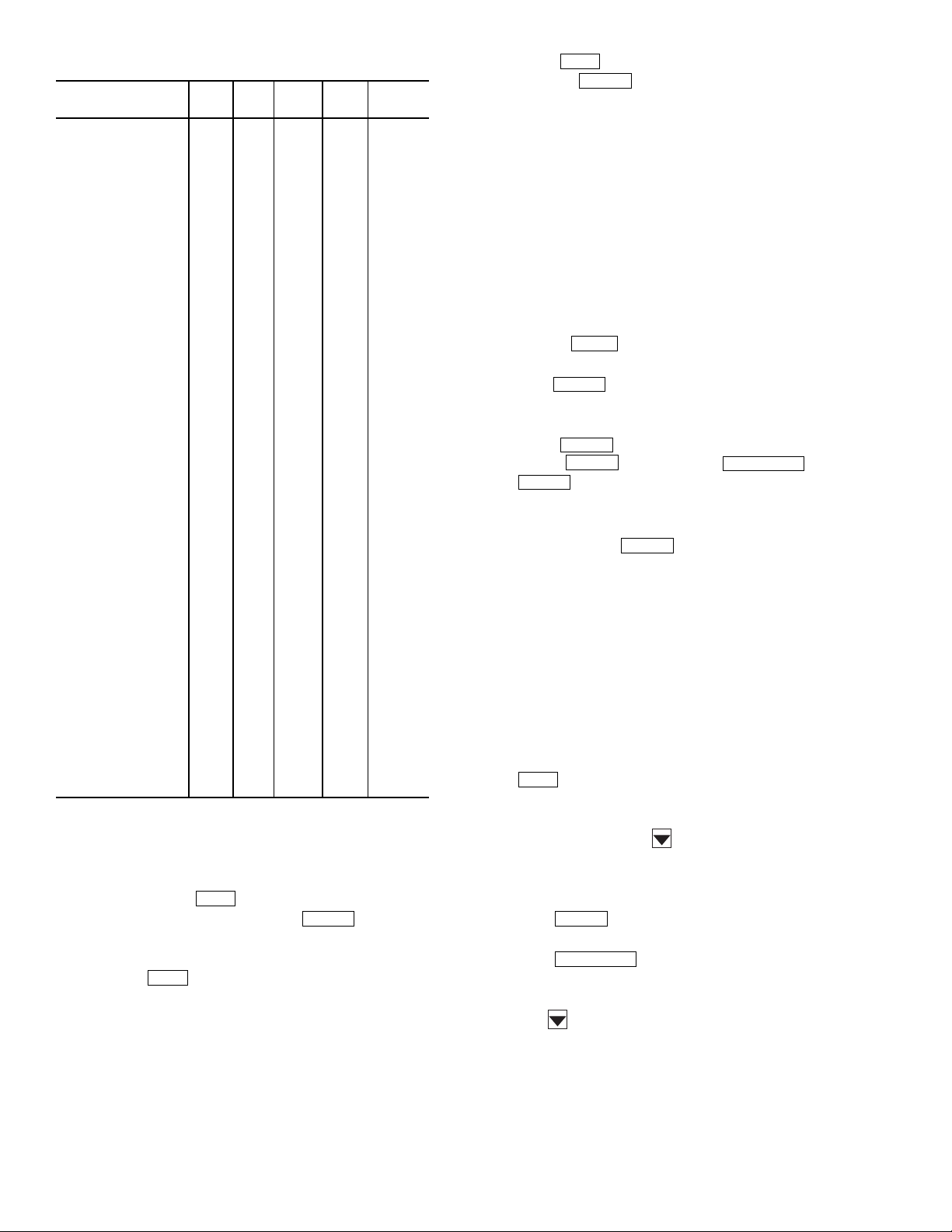
Table 7 — Controller Set Points
DESCRIPTION
DISPLAY
SCREENS
OMNIZONE::SETPT01:
Supply fan Status
Occupied Lo Setpoint 0.3 in H2O OccLow
Occupied Hi Setpoint 0.4 in H2O OccHgh
Unoccupied Lo Setpoint 0.3 in H2O UnOccLow
Unoccupied Hi Setpoint 0.4 in H2O UnOccHgh
OMNIZONE::SETPT02:
VAVRESETbaseline
Occupied Lo Setpoint 0 dF OccLow
Occupied Hi Setpoint 0 dF OccHgh
Unoccupied Lo Setpoint 0 dF UnOccLow
Unoccupied Hi Setpoint 0 dF UnOccHgh
OMNIZONE::SETPT03:
Heat\Cool Mode & Reset
Occupied Lo Setpoint 70 dF OccLow
Occupied Hi Setpoint 74 dF OccHgh
Unoccupied Lo Setpoint 55 dF UnOccLow
Unoccupied Hi Setpoint 85 dF UnOccHgh
OMNIZONE::SETPT04:
Head Pressure Control
Occupied Lo Setpoint 225 PSIG OccLow
Occupied Hi Setpoint 225 PSIG OccHgh
Unoccupied Lo Setpoint 225 PSIG UnOccLow
Unoccupied Hi Setpoint 225 PSIG UnOccHgh
OMNIZONE::SETPT05:
Supply Static Pressure
Occupied Lo Setpoint 1.5 in H2O OccLow
Occupied Hi Setpoint 1.5 in H2O OccHgh
Unoccupied Lo Setpoint 1.5 in H2O UnOccLow
Unoccupied Hi Setpoint 1.5 in H2O UnOccHgh
OMNIZONE::SETPT06:
Supply Air Temperature
Occupied Lo Setpoint 55 dF OccLow
Occupied Hi Setpoint 55 dF OccHgh
Unoccupied Lo Setpoint 55 dF UnOccLow
Unoccupied Hi Setpoint 55 dF UnOccHgh
OMNIZONE::SETPT07:
Building Static Pressure
Occupied Lo Setpoint 0.02 in H2O OccLow
Occupied Hi Setpoint 0.02 in H2O OccHgh
Unoccupied Lo Setpoint 0.02 in H2O UnOccLow
Unoccupied Hi Setpoint 0.02 in H2O UnOccHgh
OMNIZONE::SETPT08:
BSP raw control
Occupied Lo Setpoint 12.32 ma OccLow
Occupied Hi Setpoint 12.32 ma OccHgh
Unoccupied Lo Setpoint 12.32 ma UnOccLow
Unoccupied Hi Setpoint 12.32 ma UnOccHgh
OMNIZONE::SETPT09:
Humidity Control
Occupied Lo Setpoint 0 %RH OccLow
Occupied Hi Setpoint 99 %RH OccHgh
Unoccupied Lo Setpoint 0 %RH UnOccLow
Unoccupied Hi Setpoint 99 %RH UnOccHgh
LEGEND
BSP — Building Static Pressure
RH — Relative Humidity
VALUE UNITS STATUS FORCE NAME
Check System Parameters — To check system
parameters, press the button. The LID display will
show: “Hardware Points Table 1.” Press to view the
hardware points. The user can navigate up and down through
the points with the up and down arrows.
Press 2 and to display the software points. The user
STAT
can navigate up and down through the points with the up and
down arrows.
Refer to Tables 8 and 9 for hardware and software points.
STAT
ENTER
Display Alarm History — If the controller is indicating
there are alarms, the user can view the alarm history by
pressing the button. The LID display will show “Alarm
History.” Press . The LID display will show the date
HIST
ENTER
and type of alarm.
As an example, if the LID display shows:
ALARM — 10:55 11-27-02
SFS
That display indicates that on 11/27/02 at 10:55 A.M. the
system Supply Fan was either on when it had not been
commanded on or was off when it was commanded on.
The user can view other stored alarms by pressing the up
and down arrows. The twenty-four most recent alarms are
stored.
Configure Custom Programming Selections —
To configure the custom programming selections, perform the
following procedure:
1. Press 37 . The LID display will show:
Custom Program
2. Press . The LID display will show:
2.0 Global Dictionary
OMNIZONE
3. Press . The display indicates “No Data.”
Press then press . Press
ENTER
Compressor Stages
4.00
4. Press 4 and then to indicate that 4 compressors
are installed.
5. Use the down and up arrows to select the other configuration parameters as required. See Table 10 for a list of configuration parameters.
6. A field-supplied 0 to 10 vdc signal to the 50XJ unit may
be used to reset the supply-air temperature.
The reset will be taken off the supply air set point
configured in the controller. The reset range can be
changed by adjusting the High Conversion Endpoint
value of the custom voltage input to a value other than
20. For example for 10 degrees of reset change the Hi
input value to 10. This may be found by pressing 7
STAT
custom voltage input point in the controller. The first
will be CSMUX, which is the compressor status multiplexed input. Press to see the following in the
LID display:
Ext. Supply Air Reset
RESET
Press . If the LID display shows:
System Value
Press . The LID display will show:
Low Input Endpoint
2.0 Volts
Press three times to get to the High Conversion
Endpoint. The user must be logged in to be able to change this
otherwise you can only view it. See the start up section for how
to log into the controller.
Configuration parameters are shown in Table 10.
ALGO
ENTER
ENTER
CLEAR
EXPN/EDIT
again. The LID display should now show:
ENTER
from the Keypad. RESET will be the second
ENTER
EXPN/EDIT
14
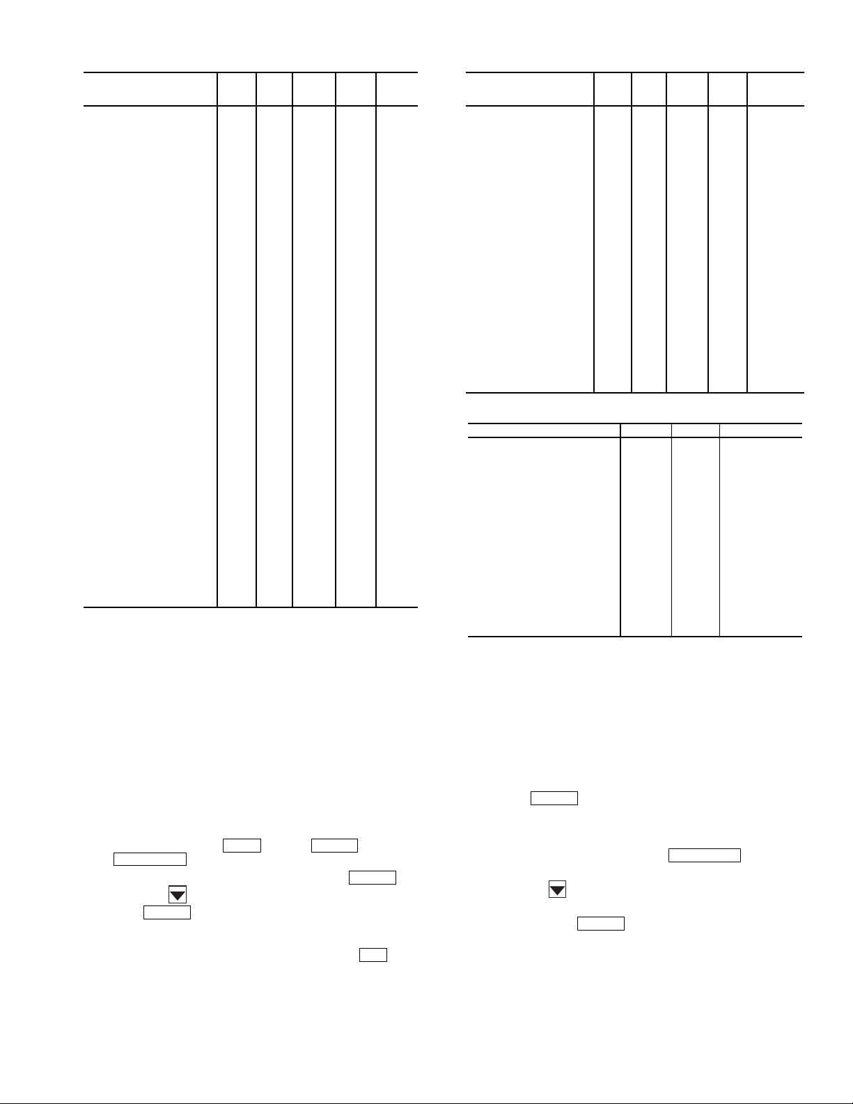
Table 8 — Controller Hardware Points Table 9 — Software Points
DESCRIPTION
DISPLAY
SCREENS
OMNIZONE::HWP01-32:
Hardware points Table 1
Supply Air Temperature 67 dF SAT
Duct Static Pressure 0.2 in H2O DSP
Comp. Status MUX 1.86 Volts CSMUX
Fire Alarm/ShutDown Enable FSD
Cond. Water Flow Switch Ye s C DW F
Remote Occupancy Disable ROCC
Duct High Press. Switch Normal DHS
Entering Water Temp. 69.9 dF EWT
Compressor 1 Relay Stop CMP1
Compressor 2 Relay Stop CMP2
Compressor 3 Relay Stop CMP3
Compressor 4 Relay Stop CMP4
Supply Fan/VFD Stop SF
VFD Speed Signal 0 % SPEED
Non Critical Fault Off WARN
Critical Fault Off ALARM
Mixed/Return Air Temp 77.2 dF MA_RA
Dirty Filter Status Clean FLTS
Phase Loss Protection Normal PHASE
Ext. Supply Air Reset 0 dF RESET
Water Econ. FreezeStat Normal FREEZ
Space_Reset Sensor 79.2 dF SPT
VFD Bypass Enable Disable BYPAS
Head Pressure(Comp1) 118.76 PSIG PRES
Ventilation Request Close VENTR
VAV Termi nals Co ntro l No TRMCT
2-position/Econo Valve 0% ECONO
Reverse/Head Press Ctrl 100 % Control MVLV
Hot Water Valve 0% HWV
Heat Interlock Relay Off HIR
Bypass Start_Stop Stop BPS_S
VAV Terminals Open MAX Close TRMOP
OMNIZONE::HWP33-64:
Hardware points table 2
Cooling Tower Sump Temp. 57.5 dF TWR
Building Static Milliamp 12.51 ma BSP
Condenser Leaving Water 70.3 dF LWT
Indoor Air Quality 587.21 IAQ
Indoor Relative Humidity 49.7 % IRH
Outdoor Air Temp. 76.1 dF OAT
Heat Stage 1 Off HEAT1
Heat Stage 2 Off HEAT2
Heat Stage 3 Off HEAT3
Heat Stage 4 Off HEAT4
Pump Request Off PUMP
Cooling Tower Request Off TOWER
Exhaust Fan 0% EXH
Ext. Dehumidification Stop DEHUM
VALUE UNITS STATUS FORCE NAME
DESCRIPTION
DISPLAY
SCREENS
OMNIZONE::SWP65-96:
Software Points
Compressor 1 Status Off CLO1
Compressor 2 Status Off CLO2
Compressor 3 Status Off CLO3
Compressor 4 Status Off CLO4
Bypass Acc Panel Secure No BP_SAFE
DX VAVRESET control 0 dF VAVRESET
Factory/Field Test Stop FLDTST
Building Static Pressure 0.03 in H2O BSP_IN
Time Clock Off TIMCLOCK
Cooling Disable COOLOK
Supply Fan Status Off Control SFS
Ok to run Fan No OKFAN
OK Fan + Sup. Fan Stat FA L SE S F_ SF S
Fan + Cond. Water Flow FA LS E FAN _C DW F
Equipment Mode Cool Control MODE
Activate Evacuation Mode Disable EVAC
Space Control Point 74 dF CTRLPT
Mod. Econ Enabled No Control ECON_OK
Head Pressure Control Disable Control HEAD
Economizer Control Temp. 77.22 dF ECONPT
Compressor Cooling Disable COMPRES
Duct Static Failure Normal DSP_ALM
Compressor 1 Alarm Normal C1_ALM
Compressor 2 Alarm Normal C2_ALM
Compressor 3 Alarm Normal C3_ALM
Compressor 4 Alarm Normal C4_ALM
Cond. Flow Alarm Status Disable Control CDWF_ST
VALUE UNITS STATUS FORCE NAME
Table 10 — Configuration Parameters
DESCRIPTION VALUE UNITS NAME
Compressor Stages 2.00 NUM_CMP
Reset Ratio 3.00 dF RSET_RTO
CDWF 0=NO,1=YES 0.00 CDFW_SWT
ECON 0=NO,1=YES 0.00 EWT_SNS
EWT Reset 0=NO,1=YES 1.00 EWT_RST
MOD.VLV 0=NO,1=YES 0.00 MOD_ECON
0=CONST.,1=VARIABLE 0.00 FLOW_TYP
0=RAT,1=MAT 2=NONE 2.00 MARA_SNS
PHASE 0=NO,1=YES 0.00 PHAS_SWT
FREEZ 0=NO,1=YES 0.00 FREZ_SWT
ENABLE ECON. 68.00 dF ECON_SET
SPT 0=NO,1=YES 0.00 SPT_SNS
PRES 0=NO,1=YES 0.00 PRES_SNS
TWR 0=NO,1=YES 0.00 TWR_SNS
LWT 0 =N O,1 =YE S 0.00 LWT_SNS
IAQ 0=NO,1=YES 0.00 IAQ_SNS
IRH 0=NO,1=YES 0.00 IRH_SNS
BSP 0=NO,1=YES 0.00 BSP_SNS
BSP Range 1.00 in H2O BSP_RNG
BSP LOW VALUE –0.50 in H2O BSP_LOW
LEGEND
BSP — Building Static Pressure
CDWF — Condenser Water Flow
ECON — Economizer
EWT — Entering Water Temperature
IAQ — Indoor Air Quality
IRH — Indoor Relative Humidity
LW T — Leaving Water Temperature
MAT — Mixed Air Temperature
RAT — Return Air Temperature
SPT — Space Temperature
Set Controller Address — To set the address of the
OMNIZONE™ System Control panel controller, perform the
following procedure:
1. Press 7 and then . Press and then
EXPN/EDIT
2. Type in the CCN element number and press .
SRVC ENTER
.
ENTER
3. Press the button. Type in the CCN bus number and
press .
ENTER
Log Off from Controller — To log off from the
OMNIZONE System controller Press 3 and then . The
controller password will be displayed.
SET
15
1. Press . The display should show:
ENTER
Log in to Controller
Logged in
If this is not displayed, Press until it is
EXPN/EDIT
displayed.
2. Press the button. The LID display will show:
Log out of Controller
Press 1. Press to log off.
ENTER

OPERATION
Occupancy Determination —
controller can determine occupancy in many ways. Local occupancy is determined by either a local schedule contained in the
CC6400 controller, the use of the ROCC discrete input point or
by setting the Local/Off/Remote switch to Local. In order for
the CC6400 schedule or ROCC point to function the Local/
Off/Remote switch must be set to Remote.
When the OMNIZONE unit is connected to a Carrier
Comfort Network and the Local/Off/Remote switch is set to
Remote, the controller occupancy can be determined by a
Network Group schedule, a Network Global schedule, or via
Linkage from a linkage device such as a ComfortID™ linkage
master.
The OMNIZONE™
Fan Control — All Variable Air Volume (VAV) units have
a Variable Frequency Drive (VFD) to provide variable fan
motor speed and thus variable airflow. Fan control turns the fan
on and off based on unit operating mode, and controls fan
speed to maintain a particular duct static pressure at a Duct
Static Pressure Sensor (DSP). The objective is to maintain a
reasonably constant supply-air exit velocity at VAV system
outlet grilles, regardless of damper opening positions. The duct
static pressure sensor is field-installed about
toward the “far end” of the ductwork. A High Duct Static
Switch (HDS) provides protection by shutting the fan down if
the duct static pressure exceeds a maximum setting.
For the 50XJ unit, a VFD interface display is mounted in
the front of the unit. A number of user-adjustable features can
be entered/changed using the keypad on the display. These
features described in detail in the Variable Frequency Drive
Control section.
2
/3of the way
Sequence of Operation — The following control
sequence of operation for the 50XJ,BV unit describes the
various sequences that occur depending upon the way an
operation is triggered and which software control points are
involved.
SUPPLY FAN — The Supply fan can be activated in any of
the following ways:
• Unoccupied space or return air temperature demand.
• Unoccupied Linkage demand.
• Local Time Schedule (TIMCLOCK software point).
• Remote Occupancy (ROCC software point).
• By placing the remote-off-local switch in the local
mode.
• Enabled by Schedule.
Once one of the above conditions exists, either TIMECLOCK or ROCC indicates ON or Enable. The software point
OKFAN will turn on followed by the points TRMCT for air
terminal control and PUMP and TOWER to request condenser
water flow and temperature control. Approximately 20 to
30 seconds later the supply fan (SF) point will turn ON and the
VFD output SPEED will increase. The SPEED point will
output a signal, determined by a PID calculation, based on the
duct static pressure DSP input and the Supply Static Pressure
set point in SETPT05.
Once the supply fan is running and the static pressure
increases above the Supply fan status set point in SETPT01, the
supply fan status point (SFS) will indicate ON and the software
point SF_SFS will indicate TRUE.
Enabled By Unoccupied Demand
Control Point” will display the current value of the sensor used
to determine unoccupied demand. The EWT sensor provides
this function for the 50BV unit. The display is based on the
— A software point “Space
sensors installed and the configuration of these sensors in the
custom configuration, or the status of linkage.
If the Return/Mixed air sensor is in the mixed airstream and
configured as such and there is no Space temperature sensor
installed and no Linkage, the Space Control Point will display
a default value of 75 F, which is above the default occupied
cooling set point and below the unoccupied cooling set point.
If this condition exists, supply air reset from a sensor and
unoccupied unit operation will not occur.
If the unit is configured to use a sensor for the Space
Control Point or if Linkage is active and the space has
unoccupied demand, the software point OKFAN will turn on
followed by the points TRMCT for air terminal control and
PUMP and TOWER to request condenser water flow and
temperature control. Approximately 20 to 30 seconds later the
SF point will turn ON and then the VFD output SPEED will
increase. If unoccupied demand is the reason the fan is on, a
control force will appear next to the OKFAN point. Otherwise
there should not be a force on that point.
If the fan is running due to unoccupied heating or cooling
demand, either the space temperature (if installed), return air
temperature or average linkage temperature must rise or drop
to within half way between the occupied and unoccupied set
points in order for the fan to turn back off.
Enabled by Switching to Local Mode
placed in the local mode the ROCC point will indicate enable.
If ROCC is ENABLED a software routine will override the
occupancy schedule so that TIMECLOCK will also turn on.
When ROCC is turned off the TIMECLOCK point will turn
off within 60 seconds.
Supply Fan Shutdown
fied and TIMECLOCK and ROCC are off and disabled,
OKFAN will turn off, SF_SFS will turn off, Tower and PUMP
will turn off, and then 5 minutes later the SF point will turn off
and the VFD speed will go to 0%.
During the 5-minute delay, the cooling and heating routines
become disabled. This delay allows a compressor that may
have just started to run for its 5-minute minimum on time with
the supply fan on. For example, if the staging routine had just
started Compressor 3 at the time the OK_FAN point changed
to OFF, the cooling routine would become disabled and compressors 1 and 2 would shut off right away. Compressor three
would continue to run for its minimum on time of 5 minutes.
The fan continues running until all compressors meet the
minimum on time and run with a load, preventing them from
shutting down due to a safety.
Supply Fan operation with Optional Bypass (50XJ)
optional VFD Bypass is installed and the Bypass switch has
been turned to Bypass, and the access panel is in place, the
software point Bypass access panel secure BB_SAFE has been
turned to ON, and the unit operation switch has been placed
back in local or remote, then the bypass start stop point BPS_S
will follow the SF point when it turns on and off. The terminal
open point TRMOP will go on with the TRMCT point before
the fan starts.
COMPRESSOR COOLING — If the fan is on and there is no
demand for Heat, the equipment mode (MODE) will be
COOL, and Cooling (COOLOK) will switch to ENABLE.
If the unit is configured for variable flow the Reverse/Head
Pressure CTRL valve will open (otherwise it will already be
open), and if there is condenser water flow (CDWF is YES),
then the Fan + Condenser water flow point will become TRUE
and the Compressor Cooling (COMRES) point will switch to
Enable.
— If the unoccupied demand is satis-
— When the switch is
—Ifthe
16

COMRES triggers the compressor staging routine that
controls the number of compressors energized. Units are
equipped with 4 compressors piped in separate refrigerant
circuits, and staged On/Off in a fixed sequential manner
(compressor no. 1 through compressor no. 4). The compressor
control routine uses a PID calculation to determine the percentage of cooling required, from 1 to 100%. Demand for the PID
calculation is determined from the supply air temperature and
the supply air set point (SETPT06).
Compressor cooling (COMPRES) will be turned off for any
of the following reasons:
• There is no condenser water flow (CDWF is Off).
• Economizer Freezestat (FREEZ) has been in alarm for
more than 15 minutes.
• MODE changes to heat.
• OK-FAN turns off during normal shut down.
• During normal compressor operation the minimum on
time is 5 minutes and the minimum off time is 5 min.
ECONOMIZER COOLING (50XJ) — The unit diverts condenser inlet water flow through an optional economizer coil to
precool evaporator entering airflow. This occurs when there is
demand for the cooling, and the temperature at an Entering
Water Temperature (EWT) thermistor is colder than the
economizer start set point. Waterflow is controlled via two
electronic water flow valves. This option also incorporates an
Economizer Freeze Switch (EFS), located at the inlet of the
economizer coil.
Economizer water flow is in series with the condensers
allowing compressor operation while the economizer is
operating.
If the Fan is on, and there is no demand for heat then the
equipment mode (MODE) will be COOL and Cooling
(COOLOK) will switch to ENABLE.
If the unit is configured for variable flow the Reverse/Head
Pressure CTRL valve will open (otherwise it will already be
open), and if there is condenser water flow (CDWF is YES)
then the Fan + Condenser water flow point will become TRUE.
If the entering-water temperature is below the Economizer
start set point in the configuration parameters table (Table 10),
then the Mod. Econ Enabled point (ECONOK) will change to
enable and the Economizer valve will modulate open to lower
the Economizer control temp to the supply air set point
(SETPT06) temperature. The economizer modulation is
controlled by a PID loop and the Reverse/Head pressure
control valve will modulate in reverse of the Economizer valve
using the formula MVLV = 100 – ECONO.
ECONOMIZER COOLING (50BV) — The unit diverts condenser inlet waterflow through an optional economizer coil to
precool evaporator entering airflow. If the entering-water
temperature is colder than the setting on the Aquastat, and the
return-air temperature is warmer than the setting on the return
air thermostat, the two-position diverting valve will direct
water to the economizer coil.
Economizer water flow is in series with the condensers
allowing compressor operation while the economizer is
operating.
COOLING RESET (50XJ) — The controller can reset the
supply air set point using these three methods:
• An external 0 to 10 volt input RESET
• The value of the space control point
• Linkage
The external 0 to 10 volt input reset is configured to produce
a 0 to 20 degree supply air reset over the 2 to 10 volt range. If
more than 1.8 volts is sensed on the input, this method of reset
takes priority over other methods.
NOTE: The reset from all methods may be limited to 10 F
or 15 F by changing the high end point of the custom
voltage input from the default (20 F) to 15 F or 10 F.
Either the return air or a space temperature sensor will be
used as the space control point. If this variable goes below the
Occupied High set point in the HEAT/COOL MODE AND
RESET set point (SETPT03), then for each degree that the
Space control point is below the set point value the supply air
set point will be reset by the value configured in the custom
configuration RESET RATIO.
If Linkage is active, for each degree that the average
occupied space temperature is below the average occupied cool
set point, the supply air set point will be reset by the amount
configured in the RESET RATIO. Reset will be limited to the
maximum value the custom voltage input RESET can display.
COOLING RESET (50BV) — The 5k ohm temperature sensor will be used as the space control point. If this variable goes
below the Occupied High set point in the HEAT/COOL
MODE AND RESET set point (SETPT03), then for each
degree that the Space control point is below the set point value
the supply air set point will be reset by the value configured in
the custom configuration RESET RATIO.
HEATING (50XJ) — The controller is configured to control
two types of heat:
• Amodulating4to20mAoutputHotWaterValve
(HWV) in the base unit, wired to the second module.
• Four stages of staged heat wired to a third, accessory
module (PCB3).
For either method of heat to function, a space control point
must be configured in the custom configuration. This control
point comes from a return air sensor or space sensor, or from
the average space temperature received through linkage.
Whenever the space control point is below the occupied or
unoccupied heat set point the mode will change to heat and if
unoccupied the fan will be started. For linkage, this occurs if
the average space temperature is below the appropriate average
heat set point.
Both heat control routines use a PID to calculate a supply air
set point that will satisfy the heat demand in the space. The
modulating output and the staged outputs will both operate at
the same time to control an attached heat source, such as steam
valves or electric heaters, to provide the supply-air temperature
required.
The heat mode changes back to cool when the space control
point is back above the occupied heat set point. For linkage, the
mode changes back to cool when the average space temperature is back above the average occupied heat set point.
When unoccupied heat is enabled the fan will be stopped
and the heat turned off when the space control temperature is
more than halfway above the difference between the occupied
heat set point and the unoccupied heat set point. For example,
if the occupied heat set point is 70 and the unoccupied heat set
point is 60 the unit will come on for unoccupied heating below
60 F and turn off again above 65 F. The average occupied and
unoccupied set points are used when linkage is active.
HEAD PRESSURE CONTROL (HPC) (50XJ) — In installations where entering water temperature can fall below 55 F,
where a water economizer (described above) is not installed,
the HPC provides 1 or 2 electronic water flow control valves to
vary flow to the condensers. Controlling the water flow
maintains compressor discharge pressure above a minimum
value, ensuring sufficient refrigerant flow out of the condenser
and throughout the refrigerant circuit. Refrigerant pressure is
measured at compressor circuit no. 1 by a Discharge Pressure
Sensor (DPS).
17

Units not equipped with a water economizer can be ordered
with the reverse/head pressure control valve factory installed
and a pressure transducer located in the discharge line of
compressor no. 1.
When the condenser water temperature gets low enough to
cause the head pressure to drop, the valve will be modulated to
control the head pressure of all four compressors by varying
the water flow through the condensers.
When the unit is operating and the COOLOK software
point is enabled and the EWT gets below 60 F, the Head
software point will become enabled and the head pressure
control valve will modulate to keep the head pressure at the
head pressure set point (SETPT04). The default set point is
225 PSI and may be set from 200 to 250 PSI. The minimum
output value for the head pressure control algorithm is 40% in
order to maintain a minimum flow through the condensers. The
valve will modulate between 40 and 100%. Do not set the
minimum lower than 40% or the compressors may shut down
due to low flow, resulting in the high-pressure switch tripping.
VENTILATION REQUEST (50XJ) — The ventilation request
output will close a set of relay contacts to activate a ventilation
damper whenever the supply fan and supply fan status are both
true and the TIMECLOCK software point is on.
VAV TERMINAL OPERATION OUTPUT (50XJ) — The
VAV terminal control output (TRMCT) closes a set of relay
contacts to indicate to non-Carrier air terminals that the fan is
either forced on or is going to turn on. This signals the
terminals to open and start controlling to the desired CFM and
Temperature set points.
VAV TERMINAL OPEN OUTPUT (50XJ) — The VAV terminal open output (TRMOP) closes a set of relay contacts to
command the air terminals to open to maximum CFM at times
when the fan is operating on the VFD Bypass.
PUMP AND TOWER OUTPUTS (50XJ) — The pump and
Tower outputs close a set of relay contacts to indicate that the
50XJ unit is in operation and may require condenser water
flow through the unit.
BUILDING PRESSURE CONTROL (50XJ) — The building
pressure control output provides an analog 4 to 20 mA signal to
control return fan or exhaust fan speed. Fan speed is modulated
to maintain the building static pressure set point (SETPT07).
The control parameters for the building pressure set point
and building pressure are read and controlled in milliamps but
are converted to inches of water for ease of setting and display.
The range and low start values of the sensor selected should be
configured in the custom configurations screen. The raw sensor
value in milliamps will be displayed on the hardware point
BSP. The converted sensor reading in inches of H
Owillbe
2
displayed at the software point BSP_IN. The set point input in
SETPT07 in inches of H
O is converted to a raw milliamp set
2
point in SETPT08. The algorithm controls to the milliamp
values since the math required for control using the static
pressure in inches generates numbers too small to be used
given the range of the controller configuration parameters.
Diagnostic Features — The CC6400 provides a number
of features to help protect the unit and allow problem
diagnosis.
CRITICAL FAULT — The controller provides an output
(for field connection) to signal an external building systems
monitor or control that the unit is not operating properly and
has shut down. A red light mounted on the front of the unit
provides visual indication of this alarm condition.
NOTE: If the Local/Off/Remote switch is in the OFF
position, it is normal for the red alarm light on the display
panel to be lit, indicating that the unit is disabled.
NON-CRITICAL FAULT — The controller provides an
output for a yellow light, mounted on the front of the unit, that
indicates the need for minor maintenance or service.
FIRE INPUT (FSD) — This is a normally closed input, which
when opened, deenergizes an isolation relay in the unit, opening
the input to the controller. When this input turns On, all control
outputs are immediately turned Off, including the fan. Unit
reset requires manual resetting at the main controller keypad.
DUCT HIGH STATIC INPUT (DHS) — This air switch
provides backup protection for the ductwork. It is factory
installed in the unit, wired to the unit main controller to receive
5 vdc. It is a normally open discreet switch, with adjustable
manual setting at the switch (range is 1 to 5 in. wg). Upon
switch closure, the controller immediately turns all outputs Off,
including fan, and then indicates an alarm both by turning On
its Alarm Output, Red Alarm light and via communications.
DIRTYFILTERSSWITCH(DFLTS)(50XJ)—Thisswitch
measures the change (delta) in air pressure across the filters.
When the delta increases beyond the preset setting, a yellow
warning light will be lit, indicating that the filters need cleaning
or replacement.
The switch receives 5 vdc from the unit controller and
monitors air pressure delta across the return air filters. Switch is
normally open, with manually adjustable setting at the switch
between 0.5 and 1.5 in. wg. Upon closure, controller should
wait to assure closure for minimum 1 minute, then indicate an
alert via its non-critical alert output and via communications.
All other unit operation should remain normal.
COMPRESSOR OVERLOAD (COL)/SAFETIES — Each
compressor circuit is provided with a temperature overload
board (Copeland Protector Bd.), a Current Overload/Sensor
Board (COL), High Pressure Switch (HPS), Low Pressure
Switch (LPS), and Evaporator Freeze Switch (EFS). These
devices are wired in series to the contactor for each compressor.
Each such circuit is then wired through a common resistor board;
such that any one or more input(s) to the main controller allows it
to discern which compressor is not operating when it should be.
The Current Overload Board (COL) is located in the unit
control box, wired in the control power line for the compressor
pilot relay (which drives the compressor contactor), and
incorporates a current loop which monitors one leg of the
compressor power leads. This board is powered along with the
related compressor contactor.
Whenever the compressor current falls below a threshold
level (i.e., compressor not operating), it activates an on-board
relay which opens power to the compressor pilot relay (i.e.,
compressor contactor), and turns On a control power feedback
line to the unit controller, via the resistor board (described
above). Any one of the safety switches described herein will
cause this event. In the event this occurs, the controller shall
turn OFF this compressor, and start the next compressor in
sequence. After a 5-minute period, the controller shall restart
this compressor, and turn the other one off, as cooling demand
requires. If the ‘problem’ compressor then operates for 10 minutes of run time normally, the unit reverts to normal operation
and compressor sequencing. If not, and the same error occurs
again, this compressor shall be shut down and replaced with
the next compressor, as before, and held off for 10 minutes. It
shall then be restarted and the other compressor shut down, as
before. If it does not run successfully for 10 minutes of normal
run time again, it is shut down and replaced a third time. This
time it is held off for 15 minutes. If the “problem” compressor
does not operate successfully for the 10 minutes of normal run
time this third time, this compressor ONLY is shut down and
locked out for servicing. Alarm output (Red light) flashes and
then remains on.
HIGH-PRESSURE SWITCH (HPS) — This switch is located
in the discharge refrigerant line of each compressor, and is set
to open at pressures above 360 psig. It is wired in the 115 vac
control power line of the compressor contactor (in series with
the LPS and EFS), and activates the COL board (above) when
it opens.
18
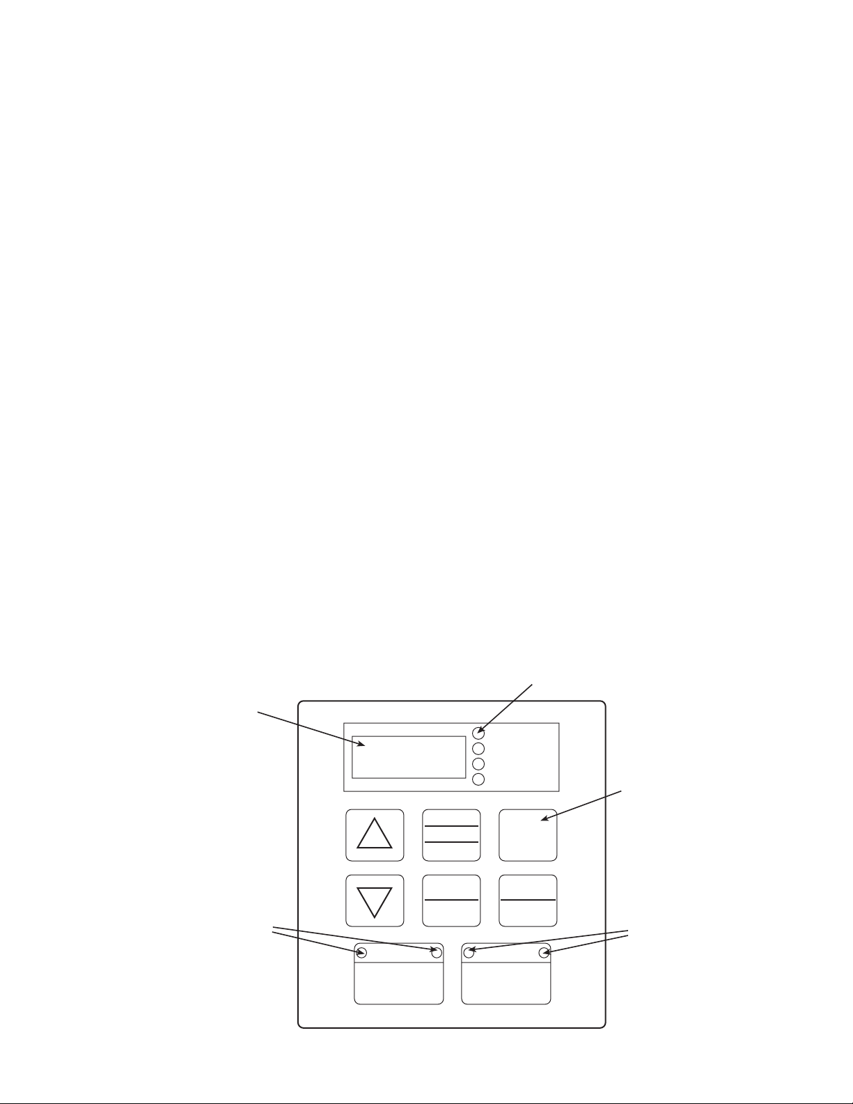
LOW-PRESSURE SWITCH (LPS) — The Low-Pressure
Switch is located in the suction refrigerant line of each
compressor, and is set to open at pressures below 27 psig. It is
wired in the 115 vac control power line of the compressor
contactor (in series with the HPS and EFS), and activates the
COL board (above) when it opens.
EVAPORATOR FREEZE SWITCH (EFS) — This is a thermal
disk type switch, mounted on a return bend of the evaporator,
refrigerant circuit for which corresponds to each respective
compressor, and is set to open at temperatures below 28 F. It is
wired in the 115 vac control power line of the compressor
contactor (in series with the HPS, and activates the COL board
(above) when it opens.
COPELAND PROTECTOR BOARD — This board is provided with each compressor, installed in the terminal box, since
these compressors do not have internal current protection. This
board activates at an overtemperature setting, and locks out
operation of the compressor for 30 minutes; there is no method
to over-ride or reset this timer. Due to this timing function,
please note that the compressor will not attempt to restart until
the third attempt described above.
ALARMS — Alarms can be provided via 4 methods; Unit
mounted Alarm Light (Red and Yellow), Keypad Display,
Network Communications, or a discreet Alarm Output to the
Field Low Voltage Terminal Strip. This field output circuit
includes an isolation relay and dry contacts. Alarms are
covered in detail in the Troubleshooting section.
50XJ Variable Frequency Drive Control — The
variable frequency drive is factory wired and programmed for
proper operation with the unit controls; no installation or
service adjustments are normally required. There is an interface
display for the VFD, independent of the main control display,
mounted on the front of the 50XJ unit.
The VFD default conditions at unit power up are: “AUTO”
run mode, “REMOTE” speed control, and “OFF” in the LED
display. When the fan is operating, the LED displays the output
frequency in Hz.
OPERATING KEYPAD — The keypad allows users to enable or disable the keypad, input commands from the keypad,
and monitor drive operation. Fig. 6 shows the operating panel
keypad layout and the locations of the keys and display LEDs.
The 7-character LED displays various values, depending
upon what mode is running.
• In Standard Monitor mode: the LED displays the current
output frequency.
• In Status Monitor mode: monitors the status conditions
and frequency command value setting.
• In Setup mode: displays setup parameter titles and values.
• In Program mode: displays parameter group titles, individual parameter names, and parameter values.
• During a trip: displays the trip title.
The appropriate local/remote LED, which is inset into the
speed control key, is lit when the unit is in Local or Remote
mode.
The appropriate manual/auto LED, which is inset into the
run mode key, is lit when the unit is Manual or Auto mode.
When numeric data is shown on the LED display, the corresponding unit indication LED will be lit. If no unit indication
LED is lit, the current data has no unit or the corresponding
unit does not exist on the display panel.
KEY FUNCTIONS — Refer to Table 11 for the functions of
each key on the keypad.
NON-TRIP MESSAGES — Non-trip messages are those that
may be displayed but do not cause a trip and are not recorded in
the fault history. Table 12 lists the non-trip messages with their
explanations.
TRIP MESSAGES — Trip messages and their causes are
shown in Table 13.
CLEARING A TRIP — A trip clear can be performed after
the cause of the trip has been removed. To perform a trip clear,
either switch off power to the inverter or use the following
procedure:
Press Stop/Reset. The display will show: CLr. Press Stop/Reset again. The display will show: 0.0, indicating that the trip is
cleared and the display will return to Standard Monitor mode.
If any key other than the STOP/RESET key is pressed at the
trip clear command prompt, the trip clear command is aborted
and the display returns to Standard Monitor mode (where the
trip title will be displayed flashing).The trip clear command
does not clear the recorded past faults.
7-CHARACTER LED
DISPLAY AREA
LOCAL/REMOTE LEDS
UNITS LED (TYPICAL 4)
HZ
PERCENT
SECONDS
KW/AMPS/VOLTS
SETUP
PROGRAM
MONITOR
READ
WRITE
LOCAL/REMOTE
SPEED CTRL
RUN
STOP
RESET
MANUAL/AUTO
RUN MODE
Fig. 6 — 50XJ VFD Display Keypad
19
KEYS (TYPICAL 8)
MANUAL/AUTO LEDS
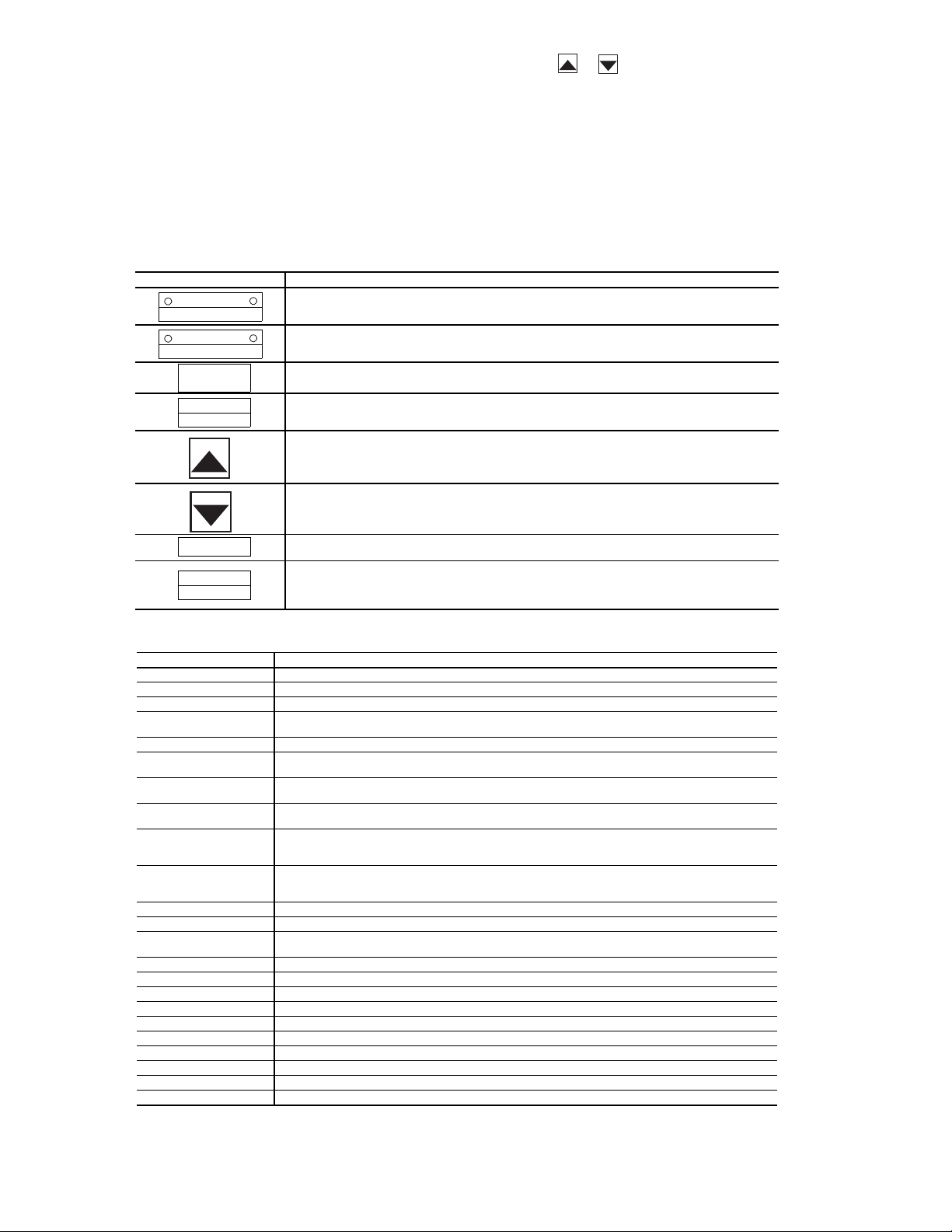
STATUS MONITOR MODE — In Status Monitor mode, it is
possible to monitor the VFD status (frequency command, output
voltage, current, terminal information, etc.). Status monitor
mode is entered by pressing the Setup/Program/Monitor key,
then selecting MON at the mode selection menu and pressing
the Read/Write key. Table 11 details the procedure for entering
status monitor mode (from standard monitor mode) and viewing
all the monitored status variables. The present output frequency
(which, just after power is applied, is 0.0) is displayed. (If the STCC terminals are not shorted, OFF will be displayed).
Table 11 — Keys and Functions for 50XJ VFD
If either or is pressed continuously, every 0.5 sec
the next/previous item will be displayed. As optional points,
RUN, STOP, displaying the frequency status, and switching to
local/remote and manual/auto modes can be performed.
MANUAL MODE — To override the automatic unit controls
and manually operate the fan from the VFD display, press keys
for “MANUAL” run mode, “LOCAL” speed control, and
press the Up or Down arrow keys to increase or decrease
output frequency.
KEY FUNCTION
LOCAL/REMOTE
SPEED CT RL
MANUAL/AUTO
RUN MODE
SETUP
PROGRAM
MONITOR
READ
WRITE
RUN
STOP
RESET
Local/Remote Key
Switches the source of frequency command information from panel/ter minal
block. The appropriate LED is lit to indicate local or remote frequency command.
Manual/Auto Key
Switches the source of run/stop command information from panel/terminal block.
The appropriate LED is lit to indicate manual or auto run/stop command.
Setup/Program/Monitor Key
Toggles between Setup, Program, Monitor, and Frequency Mode.
Read/Write Key
Mode, group, parameter, data, and frequency selection key. This key is used to
select or enter a parameter value, a frequency command, or a group name.
Up Key
Scrolls up the setting of the currently displayed parameter. If the key is held
down, the scrolling speed gradually increases. Only RAM values are changed.
Also toggles to other function group entries. Pushing Read/Write key saves the setting.
Down Key
Scrolls down the setting of the currently displayed parameter. If the key is held
down, the scrolling speed gradually increases. Only RAM values are changed.
Also toggles to other function group entries. Pushing Read/Write key saves the setting.
Run Key
This key is used to star t a RUN command (only valid when in manual control mode).
Stop/Reset Key
Functions as the STOP key and emergency stop key during local operation.
Functions as the RESET key when an inverter trip occurs. In all other modes,
emergency off is engaged when this key is pressed twice.
Table 12 — VFD Non-Trip Messages for 50XJ Unit
LED MESSAGE EXPLANATION
OFF Displayed whenever the ST-CC connection is open.
pOFF Displayed when the VFD control power supply voltage is too low.
nOFF Displayed when the VFD’s main DC bus voltage is low.
rtrY Auto-restart message: alter nately displayed with the output frequency whenever the
Err1 Displayed when 2 frequency points (F-P1,F-P2,etc.) are set too close to each other.
CLr Displayed during a pending clear command (after the STOP/RESET key has been
EOFF Displayed during a pending emergency off command (after the STOP/RESET key has
CtrL Displayed during a pending coast stop command (after the Local/Remote key has
HI This maximum value warning message “HI” will be alternately displayed in the data
LO This minimum value warning message “LO” will be alternately displayed in the data
PA SS Displayed if the correct password is entered at the password prompt.
Err Displayed if an incorrect password is entered at the password prompt.
E1 Displayed when the VFD attempts to display a number that exceeds four
db Displayed when DC injection braking is being executed.
dbon Displayed when motor shaft stationary control is being executed.
FJOG Displayed when in forward JOG mode.
rJOG Displayed when in reverse JOG mode.
L VFD/motor overload pre-alarm display.
C Overcurrent pre-alarm display.
P Overvoltage pre-alarm display.
H Overheat pre-alarm display.
t Option board communication alarm display.
InIt Displayed when the VFD is initializing values during resetting/power-up.
VFD tries to automatically restart after a non-critical trip.
pressed ONCE after a trip).
been pressed ONCE when in terminal control mode).
been pressed once when in local control mode while the VFD is running).
field of a parameter when an attempt is made to increase the setting value greater than
the parameter’s maximum value.
field of a parameter when an attempt is made to decrease the setting value less than
the parameter’s minimum value.
numerical digits.
20
 Loading...