

Page 1

Vertical Large Capacity Water Source Heat Pumps
with PURON® Refrigerant (R-410A)
Installation, Start-Up, and
Service Instructions
AQUAZONE™
50VQP084-300
50 Hz
CONTENTS
Page
SAFETY CONSIDERATIONS . . . . . . . . . . . . . . . . . . .1,2
GENERAL . . . . . . . . . . . . . . . . . . . . . . . . . . . . . . . . . . . . . . . . 2
INSTALLATION . . . . . . . . . . . . . . . . . . . . . . . . . . . . . 2-17
Step 1 — Check Jobsite . . . . . . . . . . . . . . . . . . . . . . . . 2
Step 2 — Check Unit . . . . . . . . . . . . . . . . . . . . . . . . . . . 2
• STORAGE
•PROTECTION
•INSPECT UNIT
Step 3 — Locate Unit. . . . . . . . . . . . . . . . . . . . . . . . . . . . . 6
Step 4 — Mount the Unit . . . . . . . . . . . . . . . . . . . . . . . . . 6
• DISCHARGE CONFIGURATION CONVERSION
• CONTROL BOX/MOTOR ACCESS
CONFIGURATION CONVERSION
Step 5 — Check Duct System . . . . . . . . . . . . . . . . . . . . 9
• SO U N D AT T E NUATI O N
• EXISTING DUCT SYSTEM
Step 6 — Install Condensate Drain . . . . . . . . . . . . . . . 9
• VENTING
Step 7 — Pipe Connections . . . . . . . . . . . . . . . . . . . . . 10
• WATER LOOP APPLICATIONS
• GROUND-LOOP APPLICATIONS
• GROUND-WATER APPLICATIONS
Step 8 — Wire Field Power Supply . . . . . . . . . . . . . . 11
• POWER CONNECTION
• SUPPLY VOLTAGE
• 420-VOLT OPERATION
Step 9 — Wire Field Controls. . . . . . . . . . . . . . . . . . . . 17
• THERMOSTAT CONNECTIONS
• WATER FREEZE PROTECTION
• AIR COIL FREEZE PROTECTION
• ACCESSORY CONNECTIONS
• WATER SOLENOID VALVES
PRE-START-UP . . . . . . . . . . . . . . . . . . . . . . . . . . . . . . . 17-32
System Checkout . . . . . . . . . . . . . . . . . . . . . . . . . . . . . 17
Airflow and External Static Pressure . . . . . . . . . . . 18
FIELD SELECTABLE INPUTS . . . . . . . . . . . . . . . .33,34
Complete C Control Jumper Settings. . . . . . . . . . . 33
Complete C Control DIP Switches. . . . . . . . . . . . . . 33
Deluxe D Control Jumper Settings . . . . . . . . . . . . . 33
Deluxe D Control DIP Switches . . . . . . . . . . . . . . . . 33
Deluxe D Control Accessory Relay
Configurations. . . . . . . . . . . . . . . . . . . . . . . . . . . . . . 34
START-UP . . . . . . . . . . . . . . . . . . . . . . . . . . . . . . . . . . . . 34-36
Operating Limits . . . . . . . . . . . . . . . . . . . . . . . . . . . . . . . . 34
Start Up System. . . . . . . . . . . . . . . . . . . . . . . . . . . . . . . . . 34
Scroll Compressor Rotation. . . . . . . . . . . . . . . . . . . . . 34
Unit Start-Up Cooling Mode . . . . . . . . . . . . . . . . . . . . . 35
Unit Start-Up Heating Mode . . . . . . . . . . . . . . . . . . . . . 35
Flow Regulation. . . . . . . . . . . . . . . . . . . . . . . . . . . . . . . . . 35
Flushing . . . . . . . . . . . . . . . . . . . . . . . . . . . . . . . . . . . . . . . . 35
Page
Antifreeze . . . . . . . . . . . . . . . . . . . . . . . . . . . . . . . . . . . . . . . 36
Cooling Tower/Boiler Systems . . . . . . . . . . . . . . . . . . 36
Ground Coupled, Closed Loop and Plateframe
Heat Exchanger Well Systems . . . . . . . . . . . . . . . . 36
OPERATION. . . . . . . . . . . . . . . . . . . . . . . . . . . . . . . . . . .36,37
Power Up Mode . . . . . . . . . . . . . . . . . . . . . . . . . . . . . . . . . 36
Units with Aquazone Complete C Control . . . . . . . 37
Units with Aquazone Deluxe D Control. . . . . . . . . . 37
COMPLETE C AND DELUXE D BOARD
SYSTEM TEST . . . . . . . . . . . . . . . . . . . . . . . . . . . . . 37-39
Test Mode . . . . . . . . . . . . . . . . . . . . . . . . . . . . . . . . . . . . . . . 37
Retry Mode. . . . . . . . . . . . . . . . . . . . . . . . . . . . . . . . . . . . . . 39
Aquazone Deluxe D Control LED Indicators . . . . . 39
SERVICE . . . . . . . . . . . . . . . . . . . . . . . . . . . . . . . . . . . . . .39,40
Filters
Water Coil . . . . . . . . . . . . . . . . . . . . . . . . . . . . . . . . . . . . . . . 39
Condensate Drain Pans . . . . . . . . . . . . . . . . . . . . . . . . . 39
Refrigerant System. . . . . . . . . . . . . . . . . . . . . . . . . . . . . . 39
Condensate Drain Cleaning . . . . . . . . . . . . . . . . . . . . . 39
Air Coil Cleaning . . . . . . . . . . . . . . . . . . . . . . . . . . . . . . . . 39
Condenser Cleaning . . . . . . . . . . . . . . . . . . . . . . . . . . . . 39
Checking System Charge . . . . . . . . . . . . . . . . . . . . . . . 40
Refrigerant Charging. . . . . . . . . . . . . . . . . . . . . . . . . . . . 40
Air Coil Fan Motor Removal . . . . . . . . . . . . . . . . . . . . . 40
TROUBLESHOOTING . . . . . . . . . . . . . . . . . . . . . . . . 40-43
Thermistor . . . . . . . . . . . . . . . . . . . . . . . . . . . . . . . . . . . . . . 40
Control Sensors. . . . . . . . . . . . . . . . . . . . . . . . . . . . . . . . . 40
50VQP START-UP CHECKLIST . . . . . . . . . . . CL-1,CL-2
. . . . . . . . . . . . . . . . . . . . . . . . . . . . . . . . . . . . . . . . . . . 39
IMPORTANT: Read the entire instruction manual before
starting installation.
SAFETY CONSIDERATIONS
Installation and servicing of air-conditioning equipment can
be hazardous due to system pressure and electrical components. Only trained and qualified service personnel should
install, repair, or service air-conditioning equipment.
Untrained personnel can perform basic maintenance functions of cleaning coils and filters and replacing filters. All other
operations should be performed by trained service personnel.
When working on air-conditioning equipment, observe precautions in the literature, tags and labels attached to the unit, and
other safety precautions that may apply.
Improper installation, adjustment, alteration, service, maintenance, or use can cause explosion, fire, electrical shock or
other conditions which may cause personal injury or property
damage. Consult a qualified installer, service agency, or your
distributor or branch for information or assistance. The
qualified installer or agency must use factory-authorized kits or
accessories when modifying this product. Refer to the individual instructions packaged with the kits or accessories when
installing.
Manufacturer reserves the right to discontinue, or change at any time, specifications or designs without notice and without incurring obligations.
Catalog No. 04-53500080-01 Printed in U.S.A. Form 50VQP-C1SI Pg 1 11-10 Replaces: New
Page 2
Follow all safety codes. Wear safety glasses and work
gloves. Use quenching cloth for brazing operations. Have fire
extinguisher available. Read these instructions thoroughly and
follow all warnings or cautions attached to the unit. Consult
local building codes and the National Electrical Code (NEC,
U.S.A.) for special installation requirements.
Understand the signal words — DANGER, WARNING,
and CAUTION. DANGER identifies the most serious hazards
which will result in severe personal injury or death. WARNING signifies hazards that could result in personal injury or
death. CAUTION is used to identify unsafe practices, which
would result in minor personal injury or product and property
damage.
Recognize safety information. This is the safety-alert
symbol ( ). When you see this symbol on the unit and in
instructions or manuals, be alert to the potential for personal
injury.
WARNING
Electrical shock can cause personal injury or death. Before
installing or servicing system, always turn off main power
to system. There may be more than one disconnect switch.
Turn off accessory heater power if applicable.
GENERAL
This Installation and Start-Up Instructions literature is for
Aquazone™ water source heat pump systems.
Water source heat pumps (WSHPs) are single-package vertically mounted units with electronic controls designed for
year-round cooling and heating.
IMPORTANT: The installation of water source heat pump
units and all associated components, parts, and accessories
which make up the installation shall be in accordance with
the regulations of ALL authorities having jurisdiction and
MUST conform to all applicable codes. It is the responsibility of the installing contractor to determine and comply
with ALL applicable codes and regulations.
INSTALLATION
Step 1 — Check Jobsite —
maintenance instructions are provided with each unit. Before
unit start-up, read all manuals and become familiar with the
unit and its operation. Thoroughly check out the system before
operation. Complete the inspections and instructions listed
below to prepare a unit for installation. See Table 1 for unit
physical data.
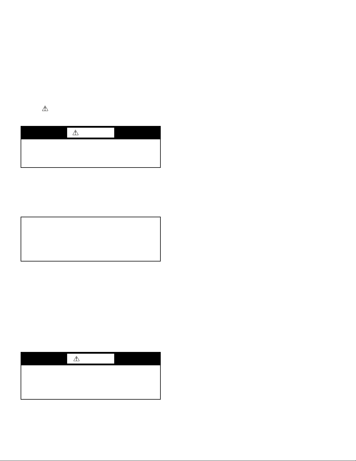
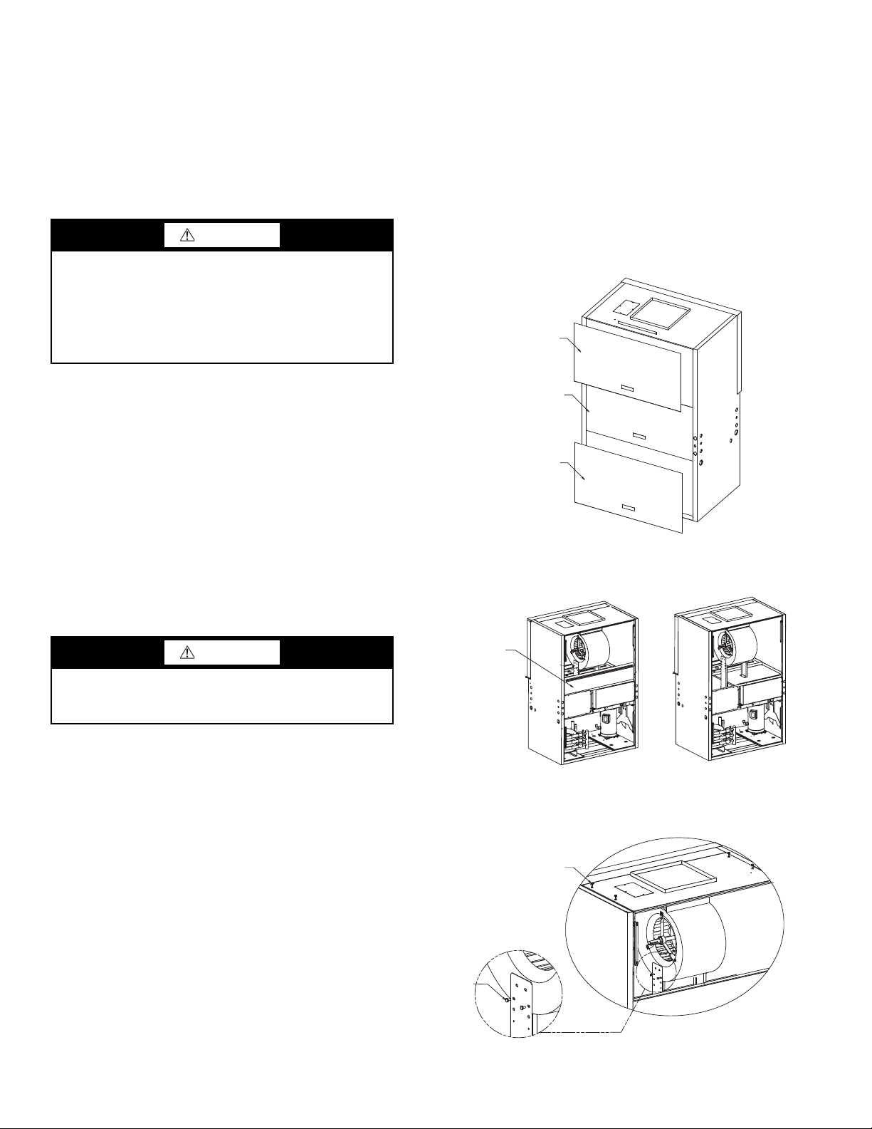
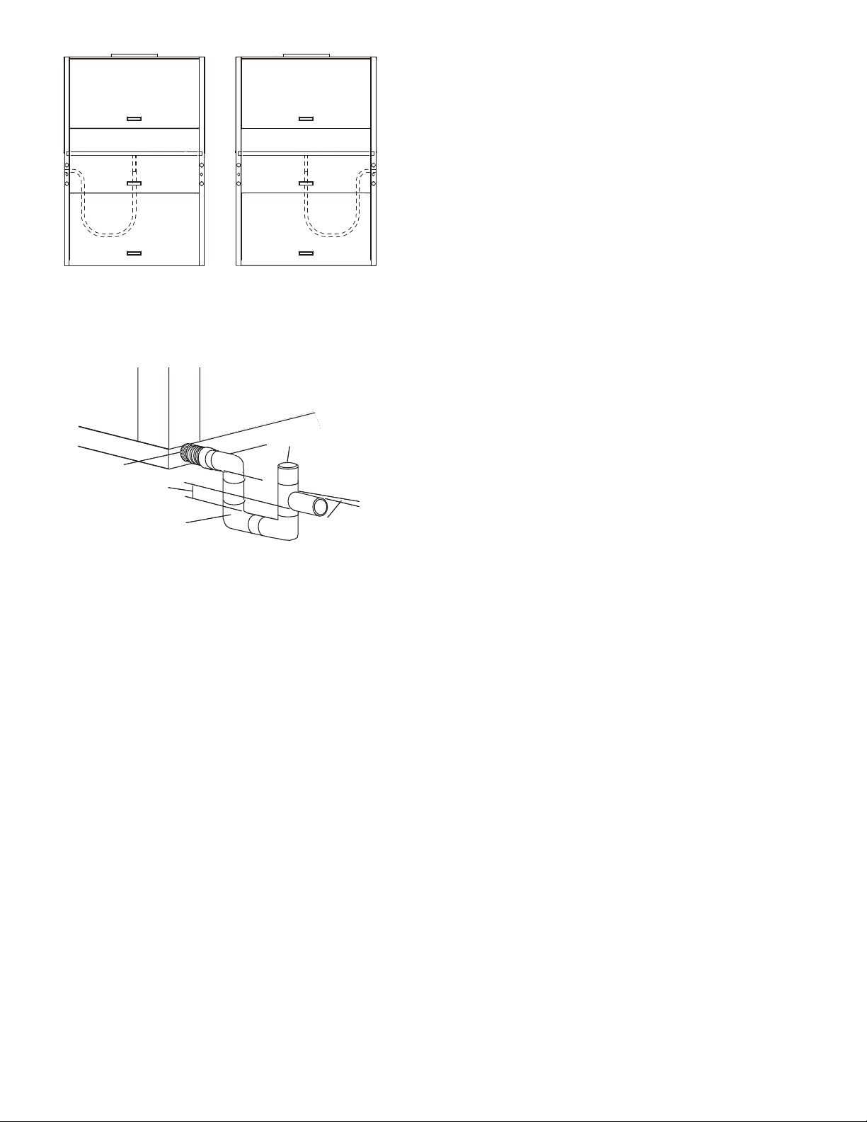
Vertical units are designed for indoor installation only and
are typically installed in a floor-level closet or a small mechanical room. Refer to Fig. 1 for an example of a typical vertical
installation. See Fig. 2 and 3 for overall unit dimensions.
Installation, operation and
Step 2 — Check Unit — Upon receipt of shipment at
the jobsite, carefully check the shipment against the bill of
lading. Make sure all units have been received. Inspect the carton or crating of each unit, and inspect each unit for damage.
Ensure the shipping company makes proper notation of any
shortages or damage on all copies of the freight bill. Concealed
damage not discovered during unloading must be reported to
the shipping company within 15 days of receipt of shipment.
NOTE: It is the responsibility of the purchaser to file all
necessary claims with the shipping company.
1. Verify unit is correct model for entering water temperature of job.
2. Be sure that the location chosen for unit installation provides ambient temperatures maintained above freezing.
Well water applications are especially susceptible to
freezing.
3. Be sure the installation location is isolated from sleeping
areas, private offices and other acoustically sensitive
spaces.
NOTE: A sound control accessory package may be used
to help eliminate sound in sensitive spaces.
4. Check local codes to be sure a secondary drain pan is not
required under the unit.
5. Be sure unit is mounted at a height sufficient to provide
an adequate slope of the condensate lines. If an appropriate slope cannot be achieved, a field-supplied condensate
pump may be required.
6. Provide sufficient space for duct connection.
7. Provide adequate clearance for filter replacement and
drain pan cleaning. Do not allow piping, conduit, etc. to
block filter access.
8. Provide sufficient access to allow maintenance and
servicing of the fan and fan motor, compressor and coils.
Removal of the entire unit from the closet should not be
necessary.
9. Provide an unobstructed path to the unit within the closet
or mechanical room. Space should be sufficient to allow
removal of unit if necessary.
10. Provide ready access to water valves and fittings, and
screwdriver access to unit side panels, discharge collar,
and all electrical connections.
11. Where access to side panels is limited, pre-removal of the
control box side mounting screws may be necessary for
future servicing.
STORAGE — If the equipment is not needed for immediate
installation upon its arrival at the jobsite, it should be left in its
shipping carton and stored in a clean, dry area of the building
or in a warehouse. Units must be stored in an upright position
at all times. If carton stacking is necessary, stack units a maximum of 3 high. Do not remove any equipment from its shipping package until it is needed for installation.
CAUTION
To avoid equipment damage, do not use these units as a
source of heating or cooling during the construction
process. The mechanical components and filters used in
these units quickly becomes clogged with construction
dirt and debris which may cause system damage.
2
Page 3
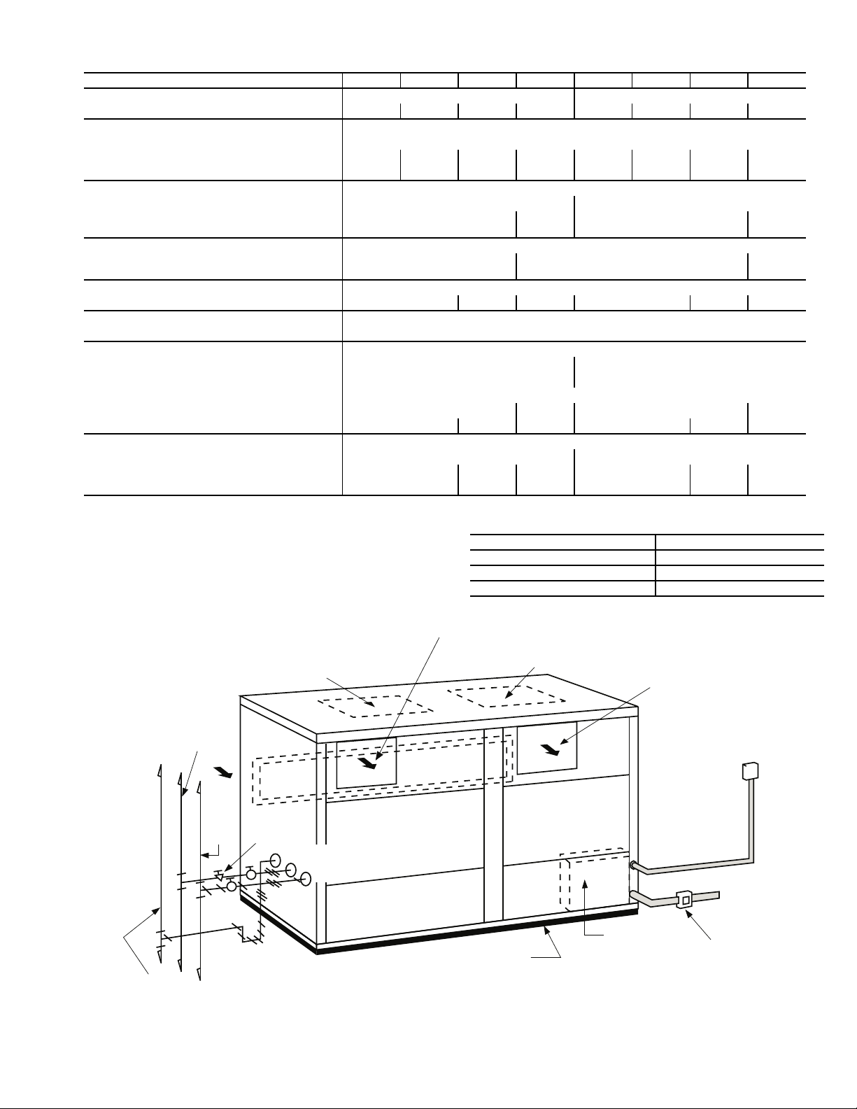
Table 1 — 50VQP Unit Physical Data
T
Optional Discharge
Supply Air
Optional Discharge
Access
Panel
Access
Panel
Access
Panel
Access
Panel
Vibration
Pad
Control Box
Supply Air
Supply Water
Return
Water
Balancing
Valve
Valves
Trap
Condensate
24 V Remote
Mtd. Stat
Power
Supply
Disconnect
Switch or
Per Local Codes
Condensate
Water In
Water Out
Unions
Fig. 1 — Typical 50VQP Unit Installation
UNIT 50VQP 084 096 120 150 168 192 240 300
COMPRESSOR QUANTITY Scroll (1) Scroll (2)
Factory Charge HFC-410A (kg) per circuit 3.97 4.42 6.35 7.03 3.97 4.42 6.35 7.03
BLOWER MOTOR
Blower Motor Quantity 1
Standard Motor (kW) .75 1.12 1.49 2.24 1.49 2.24 3.73 3.73
Large Motor (kW) 1.12 1.49 2.24 3.73 2.24 3.73 5.60 5.60
BLOWER
No. of Blowers 12
Blower Wheel Size D x W (cm) 38.1 x 27.9
38.1 x
38.1
38.1 x 27.9
WATER CONNECTION SIZE
FPT (in.) [mm] 1-1/2 [38.1] 2 [50.8]
COAX VOLUME
Volume (liters) 8.28 9.37 13.11 18.29 24.08 27.98
CONDENSATE CONNECTION SIZE
FPT (in.) [mm] 1 [25.4]
AIR COIL DATA
Air Coil Dimensions H x W (cm) 91.4 x 121.9 91.4 x 121.9
Air Coil Total Face Area (sq m) 1.11 2.22
Air Coil Tube Size (cm) 3/8 [0.953]
Air Coil Fin Spacing (fins per cm) 5.54.725.54.72
Air Coil Number of Rows 234234
MISCELLANEOUS DATA
Filter Standard Throwaway (qty) (cm) (4) 45.74 x 63.5 x 2.5 (8) 45.74 x 63.5 x 2.5
Weight - Operating (kg) 399 422 435 725 755 769
Weight - Packaged (kg) 406 429 442 739 769 782
LEGEND
FPT — Female Pipe Thread
NOTES:
1. All units have grommet and spring compressor mountings, and
2.2 cm and 3.5 cm electrical knockouts.
2. Use the lowest maximum pressure rating when multiple options
are combined:
OPTION MAXIMUM PRESSURE (kPa)
Base Unit 3100
Motorized Water Valve 2750
Internal Secondary Pump 999
38.1 x
38.1
2-1/2
[63.5]
3
Page 4
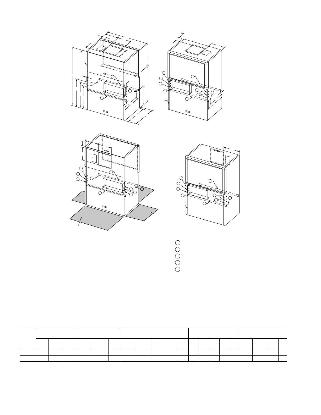
Fig. 2 — 50VQP084-150 Unit Dimensions
CONNECTIONS 50VQP084-120 50VQP150
Water Inlet (See Note 7) 11/2 in. FPT 2 in. FPT
Water Outlet (See Note 7) 11/2 in. FPT 2 in. FPT
Condensate Drain (See Note 8) 1 in. FPT 1 in. FPT
High Voltage Access (See Note 9) 1
3
/8 in. 13/8 in.
Low Voltage Access (See Note 9)
7
/8 in.
7
/8 in.
1
2
3
4
5
a50-8436
UNIT
50VQP
OVERALL
CABINET (cm)
DISCHARGE
CONNECTIONS (cm)
Duct Flange
WATER
CONNECTIONS (cm)
ELECTRICAL
KNOCKOUTS (cm)
RETURN AIR
CONNECTIONS (cm)
(Using Return Air Opening)
A
DepthBWidthCHeight
D
Supply
Width
E
Supply
Depth
FK1-Water
Inlet
L
1-Water
Outlet
M
3-
Condesate
NO1O2P QRSReturn
Depth
T
Return
Height
UV
084-120 86.4 134.9 200.7 44.5 44.6 45.1 78.7 7.6 68.6 65.1 78.7 96.4 87.7 2.5 7.6 121.9 82.2 113.3 6.9
150 86.4 134.9 200.7 54.4 44.6 45.1 78.7 7.6 68.6 65.1 78.7 96.4 87.7 2.5 7.6 121.9 82.2 113.3 6.9
LEGEND
NOTES:
1. All dimensions in centimeters.
2. Units require 0.9 m clearance for water connections, CAP, CSP, MSP, and BSP service access.
3. Overall cabinet height dimension does not include duct flange when in top discharge configuration.
4. Overall cabinet width dimension does not include filter rack and duct flange when on front or back discharge configuration.
5. Side service access must be 0.9 m on either side that connections are made. If no connections are made
on a side, then service access can be 15 mm minimum.
6. While access to all removable panels is not required, installer should take care to comply with all building
codes and allow adequate clearance for future field service.
7. Water inlet and water outlet connections are available on either side (left or right) of the unit. Two MPT
plugs are shipped loose in a plastic bag tied to the water leg in front of the unit. Installer must plug water
inlet/outlet side not being connected to.
8. Condensate drain is available on either side (left or right) of unit. Drain hose and drain connection will be
tied inside the unit. Installer must untie the drain hose and connect to the condensate drain hole of
installer’s choice.
9. Electrical access is available on either side (left or right) of unit and is also available (left or right) in the
front of the unit.
10. Overall depth — add 7.9 cm for 2.5 or 5 cm filter. Add 13 cm for 10 cm filter.
BSP —Blower Service Panel
CAP — Control Access Panel
CSP — Compressor Service Panel
MSP — Motor Service Panel
NRP — Non-Removable Panel
ALL CONFIGURATIONS REQUIRE SERVICE ACCESS AREA SHOWN BELOW
FRONT RETURN TOP DISCHARGE
NRP
AIR OUT
BSP
AIR OUT
AIR OUT
AIR OUT
NRP
NRP
NRP
NRP
NRP
NRP
NRP
NRP
NRP
Control Box
Control Box
Control Box
Control Box
NRP
CAP+MSP
RETURN AIR
RETURN AIR
RETURN AIR
RETURN AIR
BSP
BSP
BSP
CSP
CSP
BSP
N
2
2
2
2
3
3
3
3
3
3
4
4
5
5
4
4
3
4
4
5
3
4
4
5
CAP+MSP
CSP+CAP+MSP
1
1
1
1
01
02
C
P
CSP+CAP+MSP
A
NOTE 5
Q
R
S
19.3
B
D
F
T
U
L
K
M
REAR RETURN TOP DISCHARGE
4
4
5
4
4
5
19.3
F
L
K
M
REAR RETURN FRONT DISCHARGE
FRONT RETURN REAR DISCHARGE
SIDE
SERVICE ACCESS
(SEE NOTE)
SERVICE ACCESS
91 CM
FRONT AND BACK
4.3
E
F
D
F
4
Page 5
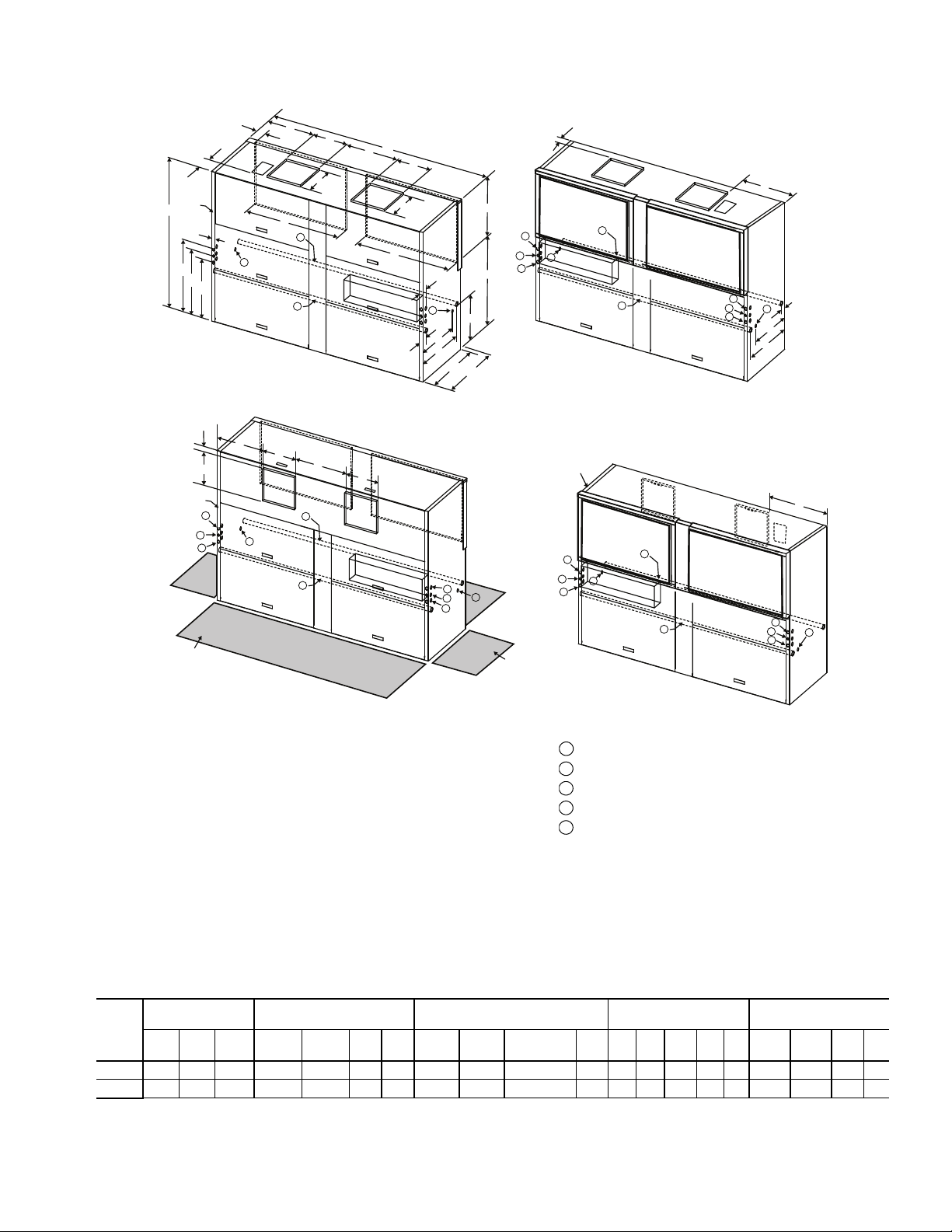
Fig. 3 — 50VQP168-300 Unit Dimensions
CONNECTIONS 50VQP168-240 50VQP300
Water Inlet (See Note 7) 2 in. FPT 21/2 in. FPT
Water Outlet (See Note 7) 2 in. FPT 2
1
/2 in. FPT
Condensate Drain (See Note 8) 1 in. FPT 1 in. FPT
High Voltage Access (See Note 9) 13/8 in. 13/8 in.
Low Voltage Access (See Note 9)
7
/8 in.
7
/8 in.
1
2
3
4
5
a50-8437
UNIT
50VQP
OVERALL
CABINET (cm)
DISCHARGE
CONNECTIONS (cm)
Duct Flange
WATER
CONNECTIONS (cm)
ELECTRICAL
KNOCKOUTS (cm)
RETURN AIR
CONNECTIONS (cm)
(Using Return Air Opening)
A
DepthBWidthCHeight
D
Supply
Width
E
Supply
Depth
FGK1-Water
Inlet
L
2-Water
Outlet
M
3-
Condensate
NO1O2P QRSReturn
Depth
T
Return
Height
UV
168-240 86.4 270.9 200.7 44.5 44.6 45.1 79.4 78.7 7.6 68.6 65.1 78.1 96.4 87.8 2.5 7.6 121.9 82.2 113.3 6.9
300 86.4 270.9 200.7 54.4 44.6 45.1 59.4 78.7 7.6 68.6 65.1 78.1 96.4 87.8 2.5 7.6 121.9 82.2 113.3 6.9
LEGEND
NOTES:
1. All dimensions in centimeters.
2. Units require 91 cm clearance for water connections, CAP, CSP, MSP, and BSP service access.
3. Overall cabinet height dimension does not include duct flange when in top discharge configuration.
4. Overall cabinet width dimension does not include filter rack and duct flange when on front or back discharge configuration.
5. Side service access must be 91 cm on either side that connections are made. If no connections are made
on a side, then service access can be 15 mm minimum.
6. While access to all removable panels is not required, installer should take care to comply with all building
codes and allow adequate clearance for future field service.
7. Water inlet and water outlet connections are available on either side (left or right) of the unit. Two MPT
plugs are shipped loose in a plastic bag tied to the water leg in front of the unit. Installer must plug water
inlet/outlet side not being connected to.
8. Condensate drain is available on either side (left or right) of unit. Drain hose and drain connection will be
tied inside the unit. Installer must untie the drain hose and connect to the condensate drain hole of
installer’s choice.
9. Electrical access is available on either side (left or right) of unit and is also available (left or right) in the
front of the unit.
10. Overall depth — add 7.9 cm for 2.5 or 5 cm filter. Add 13 cm for 10 cm filter.
BSP —Blower Service Panel
CAP — Control Access Panel
CSP — Compressor Service Panel
MSP — Motor Service Panel
NRP — Non-Removable Panel
REAR RETURN TOP DISCHARGE
FRONT RETURN TOP DISCHARGE
FRONT RETURN REAR DISCHARGE
Control Box
CSP
CSP
NRP
CAP
MSP
NRP
NRP
RETURN AIR
RETURN AIR
AIR OUT
AIR OUT
BSP
BSP
01
P
02
C
NRP
19.3
V
B
A
NOTE 5
F
D
G
D
E
S
N
U
T
K
M
L
3
2
1
R
Q
E
S
3
Control Box
CSP+MSP
NRP
NRP
RETURN AIR
RETURN AIR
AIR OUT
AIR OUT
F
L
3
1
2
3
CSP+CAP
19.3
BSP
4
5
4
4
5
4
K
M
NRP
Control Box
CSP+MSP
NRP
NRP
RETURN AIR
RETURN AIR
AIR OUT
AIR OUT
F
3
1
2
3
CSP+CAP
BSP
4
5
4
4
5
4
NRP
Control Box
CSP
NRP
CAP
MSP
NRP
AIR OUT
AIR OUT
NRP
E
NRP
4.3
F
D
G
D
2
1
3
4
5
4
4
5
4
CSP
REAR RETURN FRONT DISCHARGE
RETURN
AIR
RETURN
AIR
BSP
Side Service Access
(See Note)
Service Access
3’ (91 cm)
Front and Back
(All Configurations)
3
ALL CONFIGURATIONS REQUIRE SERVICE ACCESS AREA SHOWN BELOW
5
Page 6
PROTECTION — Once the units are properly positioned on
Fig. 4 — Remove Panels
BLOWER ACCESS
PANEL
C-BOX/
MOTOR ACCESS
PANEL
COMPRESSOR
ACCESS PANEL
a50-8466
Fig. 5 — Remove Blockoff Air Handler and Belt
BLOCKOFF
AIR HANDLER
a50-8467
Fig. 6 — Remove Bolts from
Blower Panel and Sides
STEP 3
STEP 3
a50-8468
the jobsite, they must be covered with either a shipping carton,
vinyl film, or an equivalent protective covering. Open ends of
pipes stored on the jobsite must be capped. This precaution is
especially important in areas where painting, plastering, or
spraying of fireproof material, etc. is not yet complete. Foreign
material that is allowed to accumulate within the units can prevent proper start-up and necessitate costly clean-up operations.
Before installing any of the system components, be sure to
examine each pipe, fitting, and valve, and remove any dirt or
foreign material found in or on these components.
CAUTION
DO NOT store or install units in corrosive environments or
in locations subject to temperature or humidity extremes
(e.g., attics, garages, rooftops, etc.). Corrosive conditions
and high temperature or humidity can significantly reduce
performance, reliability, and service life. Always move
units in an upright position. Tilting units on their sides may
cause equipment damage.
INSPECT UNIT — To prepare the unit for installation, complete the procedures listed below:
1. Compare the electrical data on the unit nameplate with
ordering and shipping information to verify that the
correct unit has been shipped.
2. Do not remove the packaging until the unit is ready for
installation.
3. Verify that the unit’s refrigerant tubing is free of kinks or
dents, and that it does not touch other unit components.
4. Inspect all electrical connections. Be sure connections are
clean and tight at their terminations.
5. Loosen compressor bolts until the compressor rides freely
on springs. Remove shipping restraints.
6. Remove the four
pressor support plate (two bolts on each side) to maximize vibration and sound alternation.
1
/4 in. (6 mm) shipping bolts from com-
• ALLOW enough space for service personnel to perform
maintenance.
• Provisions must be made for return air to freely enter the
space if unit needs to be installed in a confined area such
as a closet.
Step 4 — Mount the Unit — Vertical units are avail-
able in rear or front return air configurations.
DISCHARGE CONFIGURATION CONVERSION — To
change the discharge configuration of the unit from top discharge to straight (right or left) discharge, follow the procedure
below. To change the discharge configuration of the unit from
straight (right or left) discharge to top discharge, reverse the
procedure below.
1. Remove the 3 panels as shown in Fig. 4.
2. Remove blockoff air handler. Loosen belt and remove.
See. Fig. 5.
CAUTION
Failure to remove shipping brackets from spring-mounted
compressors will cause excessive noise and could cause
component failure due to added vibration.
7. Remove any blower support cardboard from inlet of the
blower.
8. Locate and verify any accessory kit located in compressor
and/or blower section.
9. Remove any access panel screws that may be difficult to
remove once unit is installed.
Step 3 — Locate Unit — The following guidelines
should be considered when choosing a location for a WSHP:
• Units are for indoor use only.
• Locate in areas where ambient temperatures are between
4.4 C and 37.8 C and relative humidity is no greater than
75%.
• Provide sufficient space for water, electrical and duct
connections.
NOTE: Water inlets/outlets and high/low voltage electrical
access are available on either side of the unit. Electrical access is also available on the unit front. See Fig. 2 and 3.
• Locate unit in an area that allows for easy access and
removal of filter and access panels.
NOTE: Unit has full filter frame bottom access for 25, 51,
or 102 mm filters.
3. Remove 4 bolts from blower panel. Remove 4 bolts (2
bolts on each side) from blower sides. See Fig. 6.
6
Page 7
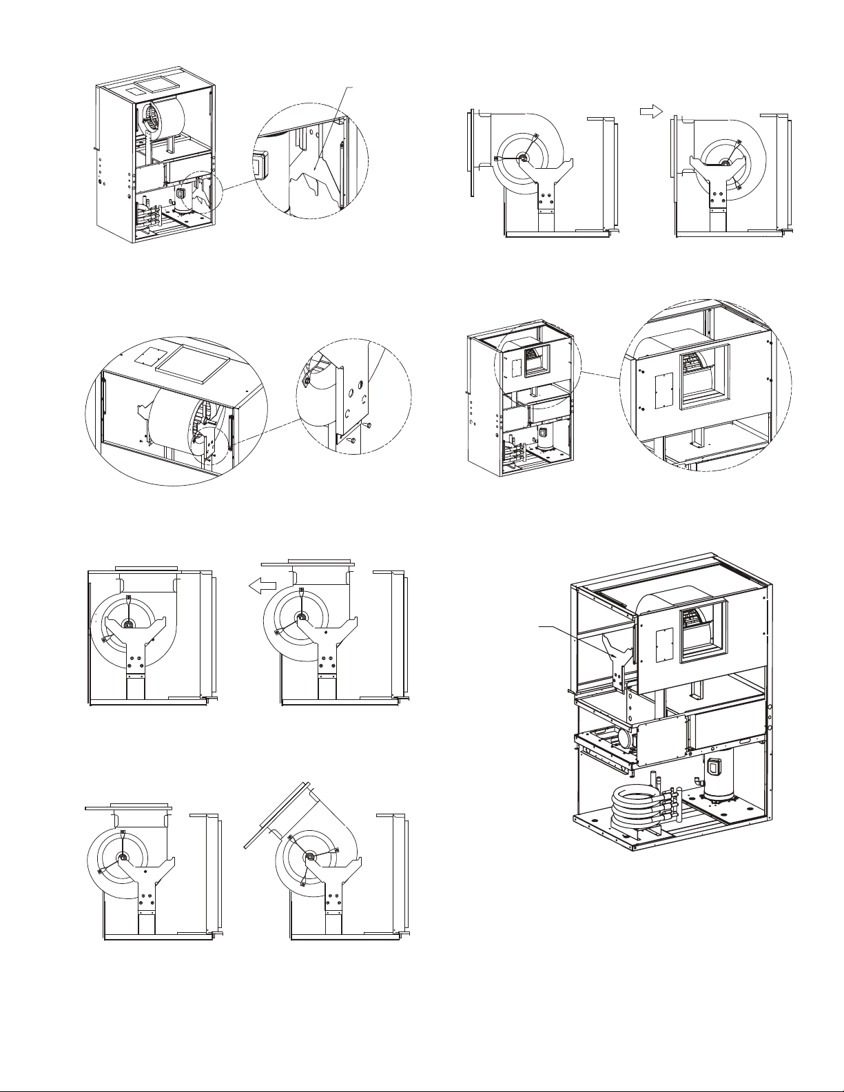
4. Remove 4 bolts and take blower glides out. See Fig. 7.
Fig. 7 — Remove Bolts and Blower Glides
BLOWER GLIDES
(2X)
a50-8469
Fig. 8 — Attach Blower Glides
a50-8470
Fig. 9 — Pull Blower Assembly to Glides
a50-8471
Fig. 10 — Rotate Blower Assembly
a50-8472
Fig. 11 — Push in Blower Assembly
a50-8473
Fig. 12 — Attach Blower Asembly
a50-8474
Fig. 13 — Remove Blower Glides and Reattach
STEP 10
a50-8475
8. When the blower assembly is parallel to the floor, push
the blower assembly back so the blower panel is flush
with the unit. See. Fig. 11.
5. Attach blower glides to blower bottom load brackets as
shown in Fig. 8. Use bottom set of holes on blower bottom load brackets. The blower shaft should be sitting directly on top of the blower glides.
6. Stand in front and pull the blower assembly on to the
ridge of the blower glides. See Fig. 9.
9. Attach blower assembly with 4 bolts as shown in Fig. 12.
10. Remove the 2 blower glides and reattach back into compressor section. See Fig. 13.
7. Rotate blower assembly using the blower glides as a
guiding track. See Fig. 10.
11. Use four
7
1
/4 in. (6 mm) 20 UNC bolts (2 bolts on each
side) to bolt blower assembly to blower bottom load
brackets. Reattach belt and tighten. See Fig. 14.
Page 8
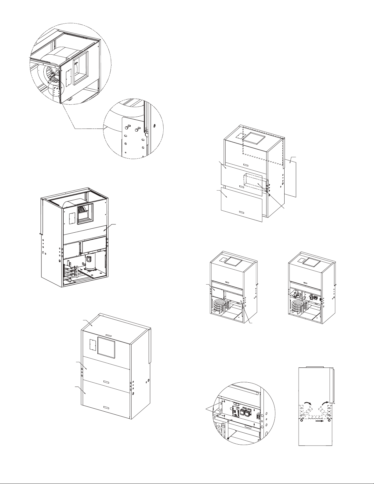
12. Reattach blockoff air handler as shown in Fig. 15.
Fig. 15 — Reattach Blockoff Air Handler
BLOCKOFF
AIR HANDLER
a50-8477
Fig. 16 — Replace Panels
BLOWER FILLER
PANEL
C-BOX/MOTOR ACCESS
PANEL
COMPRESSOR
PANEL ACCESS
a50-8478
Fig. 17 — Remove Access Panels
FRONT C-BOX/
MOTOR ACCESS
PANEL
COMPRESSOR
ACCESS PANEL
BACK COMPRESSOR/
C-BOX/ MOTOR ACCESS
PANEL
RETURN
AIR
CONTROL
BOX
a50-8479
Fig. 18 — Remove Motor and Control Box Covers
MOTOR
COVER
CONTROL BOX COVER
a50-8480
Fig. 19 — Flip Control Box
a50-8481
Fig. 14 — Bolt Blower Assembly to Load Brackets
a50-8476
1. Mount the unit so that the return-air inlet is 90 degrees to
the return-air grille. Install a sound baffle to reduce lineof-sight sound transmitted through return-air grilles.
2. Mount the unit on a rubber or neoprene pad to minimize
vibration transmission to the building structure. Extend
the pad beyond all four edges of the unit.
NOTE: Some codes require the use of a secondary drain pan
under vertical units. Check local codes for more information.
CONTROL BOX/MOTOR ACCESS CONFIGURATION
CONVERSION — To change the configuration of the control
box/motor access from the front of the unit to the back of the
unit, follow the procedure below. To change the configuration
of the control box/motor access from the back of the unit to the
front of the unit, reverse the procedure below.
1. Remove the 3 panels as shown in Fig. 17.
13. Put 3 panels back onto unit. See Fig. 16.
Sound minimization is achieved by enclosing the unit within a small mechanical room or a closet. The following are additional measures for sound control.
2. Remove motor cover and control box cover as shown in
Fig. 18.
3. Remove 4 screws from control box. Using the guide rails
as a guide, flip the control box down, slide the box across,
and then flip the box up as shown in Fig. 19. Reattach the
control box with screws.
A
SCREWS
RIGHT SIDE VIEW
C
B
8
Page 9
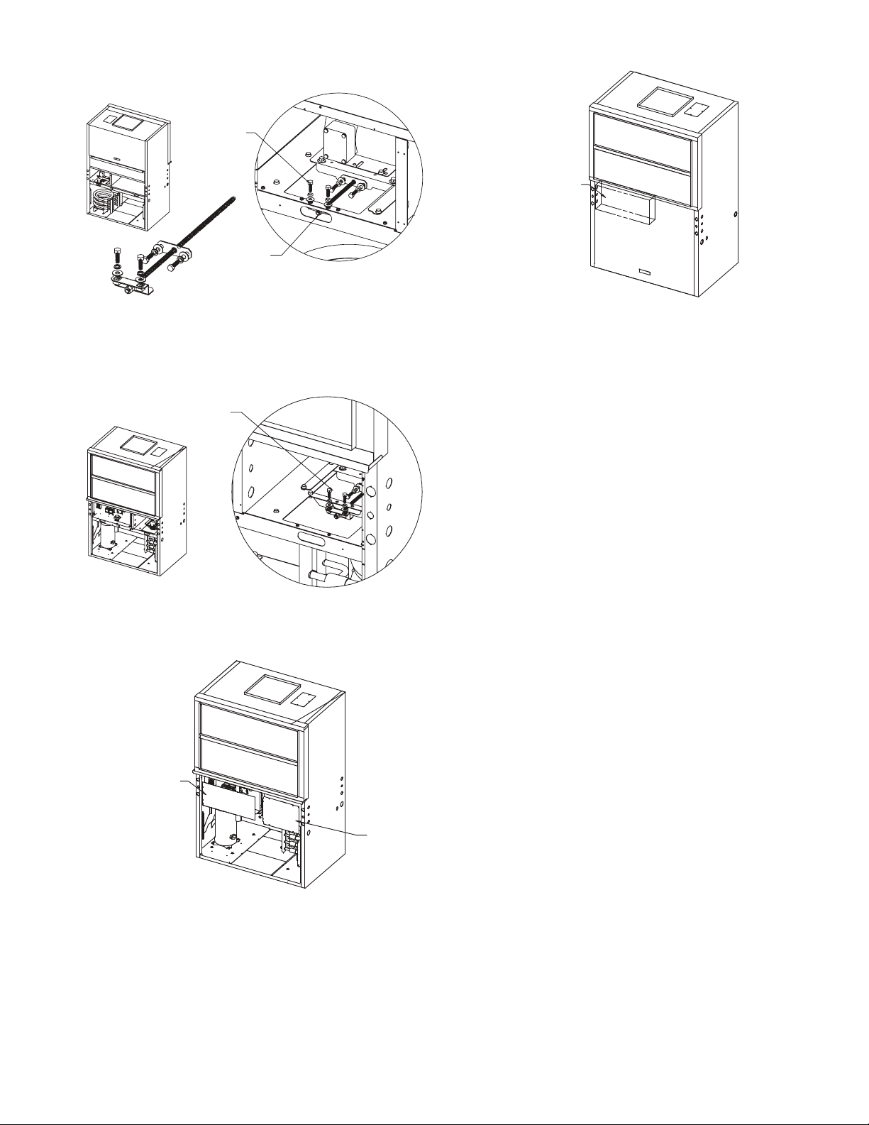
4. Loosen belt tension and take belt off. See Fig. 20.
Fig. 20 — Remove Belt and Bolt-Belt Adjustment
Assembly
STEP 5
STEP 4
BOLT-BELT ADJUSTMENT ASM
a50-8482
Fig. 21 — Move Bolt-Belt Adjustment Assembly
STEP 6
a50-8483
Fig. 22 — Replace Belt and Motor and
Control Box Covers
a50-8484
Fig. 23 — Replace Access Panels
FRONT RETURN TOP DISCHARGE
CONTROL
BOX
a50-8485
5. Remove bolt-belt adjustment assembly. See Fig. 20.
8. Put 3 panels back onto unit. See Fig. 23.
6. Move bolt-belt adjustment assembly to opposite side and
reattach. See Fig. 21.
7. Put belt back on and tighten. Put control box cover and
motor cover on return side. See Fig. 22.
CONTROL BOX
COVER
MOTOR
COVER
Step 5 — Check Duct System — The duct system
should be sized to handle the design airflow quietly.
NOTE: Depending on the unit, the fan wheel may have a shipping support installed at the factory. This must be removed
before operating unit.
SOUND ATTENUATION — To eliminate the transfer of
vibration to the duct system, a flexible connector is recommended for both discharge and return air duct connections on
metal duct systems. The supply and return plenums should include internal duct liner of fiberglass or be made of duct board
construction to maximize sound attenuation of the blower.
Installing the WSHP unit to uninsulated ductwork in an unconditioned space is not recommended since it will sweat and
adversely affect the unit’s performance.
To reduce air noise, at least one 90-degree elbow could be
included in the supply and return air ducts, provided system
performance is not adversely impacted. The blower speed can
be also changed in the field to reduce air noise or excessive airflow, provided system performance is not adversely impacted.
EXISTING DUCT SYSTEM — If the unit is connected to
existing ductwork, consider the following:
• Verify that the existing ducts have the proper capacity to
handle the unit airflow. If the ductwork is too small,
larger ductwork should be installed.
• Check existing ductwork for leaks and repair as
necessary.
NOTE: Local codes may require ventilation air to enter the
space for proper indoor air quality. Hard-duct ventilation may
be required for the ventilating air supply. If hard ducted ventilation is not required, be sure that a proper air path is provided
for ventilation air to unit to meet ventilation requirement of the
space.
Step 6 — Install Condensate Drain — The con-
densate drain can be connected to either side of the unit. The
50VQP units come with a flex hose and 1 in. (25 m) FPT condensate connection tied inside. To install the condensate drain
(see Fig. 24.):
1. Untie the flex hose and make interal trap on either the left
side or right side of the unit.
2. Internally attach mounting plate with FPT fitting.
9
Page 10
Each unit must be installed with its own individual trap,
NOTE: Trap should be deep enough to offset maximum unit static
difference.
Fig. 25 — Trap Condensate Drain
*3/4" IPT
Trap Depth
1.5" [38mm]
Min 1.5"
[38mm]
1/4" per foot
(21mm per m)
drain slope
3/4" PVC or
Copper by others
Vent
Fig. 24 — Install Condensate Drain
a50-8486
vent and means to flush or blow out the condensate drain line.
Do not install units with a common trap or vent. See Fig. 25.
Consider the following:
• Units are typically installed directly above each other on
successive floors with condensate drains located near the
units.
• Connect the unit condensate drain connection to the
building condensate drain with a 1-in. (25 mm) drain
line.
• The horizontal run of a condensate hose is usually too
short to cause drainage problems, however the horizontal
run pitch of the condensate line should be at least 1 cm
for every 50 cm of run in the direction of flow. Avoid low
points and unpitched piping since dirt collects in low or
level areas and may cause stoppage and overflow.
• Install a condensate trap at each unit with the top of
the trap positioned below the unit condensate drain
connection.
• Design the length of the trap (water-seal) based upon the
amount of positive or negative pressure on the drain pan.
As a rule, 25 mm of trap is required for each 10 Pa of
negative pressure on the unit.
VENTING — A vent should be installed in the condensate
line of any application which may allow dirt or air to collect in
the line. Consider the following:
• Always install a vent where an application requires a
long horizontal run.
• Always install a vent where large units are working
against higher external static pressure and to allow
proper drainage for multiple units connected to the same
condensate main.
• Be sure to support the line where anticipated sagging
from the condensate or when “double trapping” may
occur.
• If condensate pump is present on unit, be sure drain connections have a check valve to prevent back flow of condensate into other units.
Step 7 — Pipe Connections — Depending on the
application, there are 3 types of WSHP piping systems to choose
from: water loop, ground-water and ground loop. Refer to the
Carrier System Design Manual for additional information.
All WSHP units utilize low temperature soldered female
pipe thread fittings for water connections to prevent annealing
and out-of-round leak problems which are typically associated
with high temperature brazed connections. Refer to Table 1 for
connection sizes. When making piping connections, consider
the following:
• A backup wrench must be used when making screw connections to unit to prevent internal damage to piping.
• Insulation may be required on piping to avoid condensation in the case where fluid in loop piping operates at
temperatures below dew point of adjacent air.
• Piping systems that contain steel pipes or fittings may
be subject to galvanic corrosion. Dielectric fittings may
be used to isolate the steel parts of the system to avoid
galvanic corrosion.
WATER LOOP APPLICATIONS — Water loop applications
usually include a number of units plumbed to a common piping system. Maintenance to any of these units can introduce air
into the piping system. Therefore, air elimination equipment
comprises a major portion of the mechanical room plumbing.
The flow rate is usually set between 2.41 and 3.23 L/m per
kW of cooling capacity. For proper maintenance and servicing,
pressure-temperature (P/T) ports are necessary for temperature
and flow verification.
In addition to complying with any applicable codes, consid-
er the following for system piping:
• Piping systems utilizing water temperatures below
10.0 C require 13 mm closed cell insulation on all piping
surfaces to eliminate condensation.
• All plastic to metal threaded fittings should be avoided
due to the potential to leak. Use a flange fitted substitute.
• Teflon tape thread sealant is recommended to minimize
internal fouling of the heat exchanger.
• Use backup wrench. Do not overtighten connections.
• Route piping to avoid service access areas to unit.
• The piping system should be flushed prior to operation to
remove dirt and foreign materials from the system.
GROUND-LOOP APPLICATIONS — Temperatures between –3.9 and 43.3 C and a cooling capacity of 2.41 to
3.23 L/s per kW are recommended. In addition to comply-
ing with any applicable codes, consider the following for
system piping:
• Piping materials should be limited to only polyethylene
fusion in the buried sections of the loop.
• Galvanized or steel fittings should not be used at any
time due to corrosion.
• All plastic to metal threaded fittings should be avoided
due to the potential to leak. Use a flange fitted substitute.
• Do not overtighten connections.
• Route piping to avoid service access areas to unit.
• Pressure-temperature (P/T) plugs should be used to measure flow of pressure drop.
GROUND-WATER APPLICATIONS — Typical groundwater piping is shown in Fig. 26. In addition to complying
with any applicable codes, consider the following for system piping:
• Install shut-off valves for servicing.
• Install pressure-temperature plugs to measure flow and
temperature.
10
Page 11
• Boiler drains and other valves should be connected using
a “T” connector to allow acid flushing for the heat
exchanger.
• Do not overtighten connections.
• Route piping to avoid service access areas to unit.
• Use PVC SCH80 or copper piping material.
NOTE: PVC SCH40 should not be used due to system high
pressure and temperature extremes.
Water Supply and Quantity
supply should be plentiful and of good quality. See Table 2 for
water quality guidelines.
IMPORTANT: Failure to comply with the above required
water quality and quantity limitations and the closedsystem application design requirements may cause damage
to the tube-in-tube heat exchanger that is not the responsibility of the manufacturer.
In all applications, the quality of the water circulated
through the heat exchanger must fall within the ranges listed in
the Water Quality Guidelines table. Consult a local water treatment firm, independent testing facility, or local water authority
for specific recommendations to maintain water quality within
the published limits.
— Check water supply. Water
Step 8 — Field Power Supply Wiring
WARNING
To avoid possible injury or death due to electrical shock,
open the power supply disconnect switch and secure it in
an open position during installation.
CAUTION
Use only copper conductors for field-installed electrical
wiring. Unit terminals are not designed to accept other
types of conductors.
All field-installed wiring, including the electrical ground,
MUST comply with the National Electrical Code (NEC) as
well as applicable local codes. In addition, all field wiring must
conform to the Class II temperature limitations described in the
NEC.
Refer to unit wiring diagrams Fig. 27-30 for a schematic of
the field connections which must be made by the installing (or
electrical) contractor. See Tables 3 and 4 for fuses sizes.
Consult the unit wiring diagram located on the inside of the
compressor access panel to ensure proper electrical hookup.
The installing (or electrical) contractor must make the field
connections when using field-supplied disconnect.
Operating voltage must be the same voltage and phase as
shown in electrical data shown in Tables 3 and 4.
Make all final electrical connections with a length of flexi-
ble conduit to minimize vibration and sound transmission to
the building.
POWER CONNECTION — Line voltage connection is
made by connecting the incoming line voltage wires to the
L side of the CC terminal. See Tables 3 and 4 for correct
wire and maximum overcurrent protection sizing.
SUPPLY VOLTAGE — Operating voltage to unit must be
within voltage range indicated on unit nameplate.
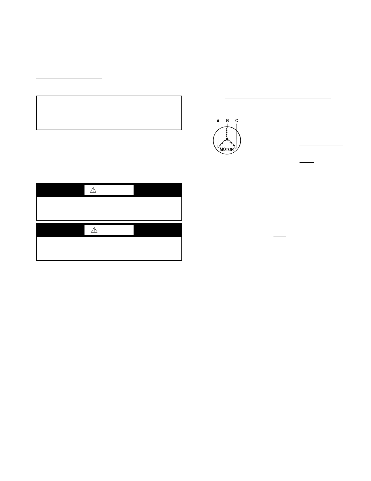
On 3-phase units, voltages under load between phases must
be balanced within 2%. Use the following formula to determine the percentage voltage imbalance:
% Voltage Imbalance
= 100 x
Example: Supply voltage is 420-3-50.
Determine maximum deviation from average voltage:
(AB) 425 – 421 = 4 v
(BC) 422 – 421 = 1 v
(AC) 421 – 418 = 3 v
Maximum deviation is 4 v.
Determine percent voltage imbalance.
% Voltage Imbalance = 100 x
below the maximum allowable 2%.
imbalance constitutes abuse and may cause damage to electrical components.
NOTE: If more than 2% voltage imbalance is present, contact
local electric utility.
420-VOLT OPERATION — All 380/420 volt units are factory
wired for 380 volts. The transformers may be switched to
420-volt operation (as illustrated on the wiring diagram) by
disconnecting the VIO lead at L1 and attaching the BRN lead
to L1. Close open end of VIO lead.
max voltage deviation from average voltage
average voltage
AB = 425 volts
BC = 422 volts
AC = 417 volts
Average Voltage =
4
421
= 0.95%
This amount of phase imbalance is satisfactory as it is
Operation on improper line voltage or excessive phase
425 + 422 + 417
1264
=
3
= 421
3
11
Page 12
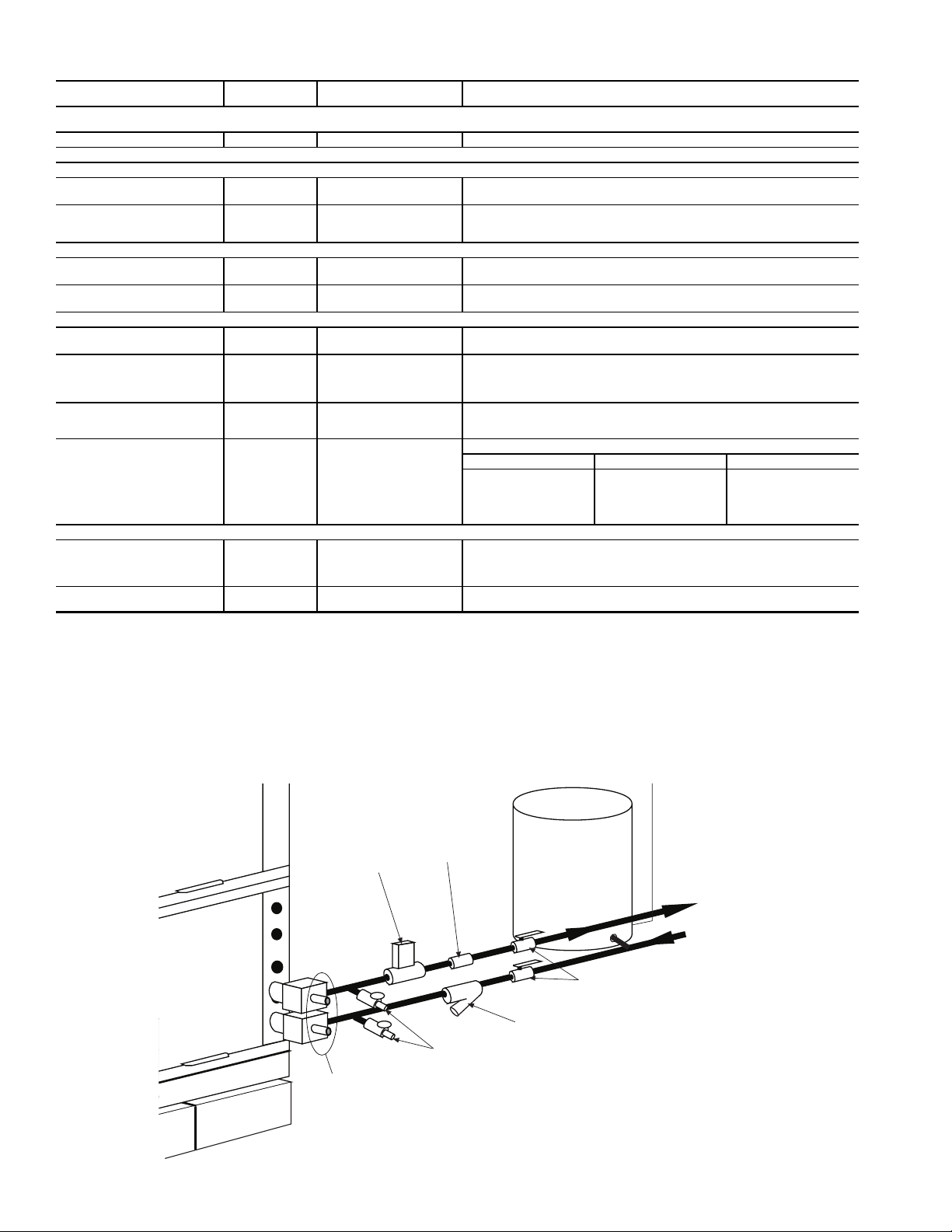
Table 2 — Water Quality Guidelines
PressureTemperature
Plugs
Boiler
Drains
Strainer – Field-Installed Accessory
(16 to 20 mesh recommended for
filter sediment)
Shut-Off
Valve
Water
Control
Valve
Automatic
Balance Valve
Expansion
Tank
Water Out
Water In
From Pump
Fig. 26 — Typical Ground-Water Piping Installation
CONDITION
Scaling Potential — Primary Measurement
Above the given limits, scaling is likely to occur. Scaling indexes should be calculated using the limits below.
pH/Calcium Hardness Method All N/A pH < 7.5 and Ca Hardness, <100 ppm
Index Limits for Probable Scaling Situations (Operation outside these limits is not recommended.)
Scaling indexes should be calculated at 150 F for direct use and HWG applications, and at 90 F for indirect HX use. A monitoring plan should be implemented.
Ryznar Stability Index
Langelier Saturation Index
Iron Fouling
2+
Iron Fe
(Ferrous)
(Bacterial Iron Potential)
Iron Fouling
Corrosion Prevention††
pH
Hydrogen Sulfide (H
Ammonia Ion as Hydroxide,
Chloride, Nitrate and Sulfate
Compounds
Maximum Chloride Levels Maximum allowable at maximum water temperature.
Erosion and Clogging
Particulate Size and Erosion
Brackish
HWG — Hot Water Generator
HX — Heat Exchanger
N/A — Design Limits Not Applicable Considering Recirculating Potable Water
NR — Application Not Recommended
SS — Stainless Steel
*Heat exchanger materials considered are copper, cupronickel, 304 SS (stain-
less steel), 316 SS, titanium.
†Closed recirculating system is identified by a closed pressurized piping system.
**Recirculating open wells should observe the open recirculating design
considerations.
S)
2
LEGEND
HX
MATERIAL*
All N/A
All N/A
All N/A
All N/A
All
All N/A
All N/A
Copper N/A
Cupronickel N/A <150 ppm NR NR
304 SS N/A <400 ppm <250 ppm <150 ppm
316 SS N/A <1000 ppm <550 ppm <375 ppm
Titanium N/A >1000 ppm >550 ppm >375 ppm
All
All N/A
CLOSED RECIRCULATING† OPEN LOOP AND RECIRCULATING WELL**
6.0 - 7.5
–0.5 to +0.5
<0.2 ppm (Ferrous)
<0.5 ppm of Oxygen
6 - 8.5
<0.5 ppm
<0.5 ppm
6 - 8.5
Monitor/treat as needed.
<10 ppm of particles and a
maximum velocity of 6 fps.
Filtered for maximum
800 micron size.
If >7.5 minimize steel pipe use.
Based upon 150 F HWG and direct well, 85 F indirect well HX.
2+
(ferrous) >0.2 ppm with pH 6 - 8, O2<5 ppm check for iron bacteria.
If Fe
Minimize steel pipe below 7 and no open tanks with pH <8.
S>0.2 ppm, avoid use of copper and cupronickel piping or HXs.
At H
2
Copper alloy (bronze or brass) cast components are okay to <0.5 ppm.
50 F (10 C) 75 F (24 C) 100 F (38 C)
<20 ppm NR NR
<10 ppm (<1 ppm “sandfree” for reinjection) of particles and a maximum velocity of
6 fps. Filtered for maximum 800 micron size. Any particulate that is not removed can
potentially clog components.
Use cupronickel heat exchanger when concentrations of calcium or sodium chloride
are greater than 125 ppm are present. (Seawater is approximately 25,000 ppm.)
††If the concentration of these corrosives exceeds the maximum allowable level,
then the potential for serious corrosion problems exists.
Sulfides in the water quickly oxidize when exposed to air, requiring that no agitation occur as the sample is taken. Unless tested immediately at the site, the
sample will require stabilization with a few drops of one Molar zinc acetate
solution, allowing accurate sulfide determination up to 24 hours after sampling. A low pH and high alkalinity cause system problems, even when both
values are within ranges shown. The term pH refers to the acidity, basicity, or
neutrality of the water supply. Below 7.0, the water is considered to be acidic.
Above 7.0, water is considered to be basic. Neutral water contains a pH of 7.0.
NOTE: To convert ppm to grains per gallon, divide by 17. Hardness in mg/l is
equivalent to ppm.
If <–0.5 minimize steel pipe use.
Above this level deposition will occur.
Rotten egg smell appears at 0.5 ppm level.
12
Page 13
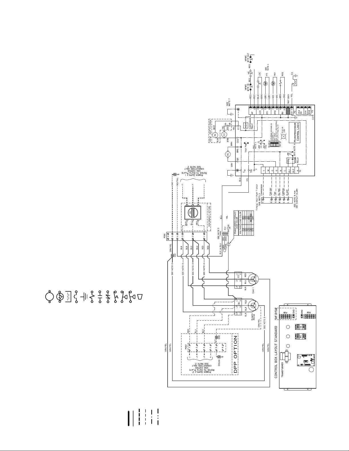
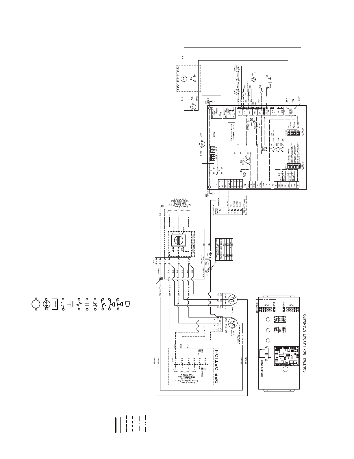
Fig. 27 — 50VQP084-168 Unit with Complete C Control (Typical)
a50-8438
NOTES:
1. Compressor and blower motor thermally protected internally.
2. All wiring to the unit must comply with NEC (National Electrical Code, U.S.A.) and local codes.
3. 380/420-v transformers will be connected for 380-v operation. For 420-v operation, disconnect
VIO lead at L1, and attach BRN lead to L1. Close open end of VIO lead.
4. FPI jumper provides low temperature protection for WATER. When using ANTIFREEZE solu-
tions, cut JW3 jumper.
5. Typical heat pump thermostat wiring shown. Refer to thermostat installation instructions for wir-
ing to the unit. Thermostat wiring must be “Class 1” and voltage rating equal to or greater than
unit supply voltage.
6. 24-v alarm signal shown. For dry alarm contact, cut JW1 jumper and dry contact will be avail-
able between AL1 and AL2.
7. Transformer secondary ground via Complete C board standoffs and screws to control box.
(Ground available from top two standoffs as shown.)
8. For dual point power option, blower wires (3 qty) will go to PDB2 only.
AL — Alarm Relay
BC — Blower Contactor
CB — Circuit Breaker
CC — Compressor Contactor
CO — Sensor, Condensate Overflow
DPP — Dual Point Power
DS — Disconnect Switch
FP1 — Sensor, Water Coil Freeze Protection
FP2 — Sensor, Air Coil Freeze Protection
HP — High-Pressure Switch
HPWS — High-Pressure Water Switch
JW3 — Clippable Field Selection Jumper
LOC — Loss of Charge Pressure Switch
MV — Motorized Valve
PDB1 — Power Distribution Block
PDB2 — Power Distribution Block Dual Point Option
RVS — Reversing Valve Solenoid
TRANS — Transformer
Factory Line Voltage Wiring
Factory Low Voltage Wiring
Field Line Voltage Wiring
Field Low Voltage Wiring
Printed Circuit Trace
Optional Wiring
LEGEND
Relay/Contactor Coil
Thermistor
Condensate Pan
Circuit Breaker
Ground
Solenoid Coil
Relay Contacts - N.O.
Relay Contacts - N.C.
Temperature Switch
Switch - Low Pressure
Switch - High Pressure
Wire Nut
Complete C
13
Page 14
NOTES:
1. Compressor and blower motor thermally protected internally.
2. All wiring to the unit must comply with NEC (National Electrical Code) and local codes.
3. 380/420-v transformers will be connected for 380-v operation. For 420-v operation, dis-
connect VIO lead at L1, and attach BRN lead to L1. Close open end of VIO lead.
4. FP1 thermistor provides freeze protection for WATER. When using ANTIFREEZE solu-
tion, cut JW3 jumper.
5. Typical heat pump thermostat wiring shown. Refer to thermostat installation instructions
for wiring to the unit. Thermostat wiring must be “Class 1” and voltage rating equal to or
greater than unit supply voltage.
6. 24-v alarm signal shown. For dry alarm contact, cut AL2 DRY (JW4) jumper and dry con-
tact will be available between AL1 and AL2.
7. Transformer secondary ground via Deluxe D board standoffs and screws to control box.
(Ground available from top two standoffs as shown.)
8. For dual point power option, blower wires (3 qty) will go to PDB2 only.
AL — Alarm Relay
BC — Blower Contactor
CB — Circuit Breaker
CC — Compressor Contactor
CO — Sensor, Condensate Overflow
DPP — Dual Po int Power
DS — Disconnect Switch
FP1 — Sensor, Water Coil Freeze Protection
FP2 — Sensor, Air Coil Freeze Protection
HP — High-Pressure Switch
HPWS — High-Pressure Water Switch
JW3 — Clippable Field Selection Jumper
LOC — Loss of Charge Pressure Switch
MV — Motorized Valve
PDB — Power Distribution Block
PDB2 — Power Distribution Block Dual Point Option
RVS — Reversing Valve Solenoid
TRANS — Transformer
Factory Line Voltage Wiring
Factory Low Voltage Wiring
Field Line Voltage Wiring
Field Low Voltage Wiring
Printed Circuit Trace
Optional Wiring
LEGEND
Relay/Contactor Coil
Thermistor
Condensate Pan
Circuit Breaker
Ground
Solenoid Coil
Relay Contacts - N.O.
Relay Contacts - N.C.
Temperature Switch
Switch - Low Pressure
Switch - High Pressure
Wire Nut
Fig. 28 — 50VQP084-168 with Deluxe D Control (Typical)
a50-8439
Deluxe D
14
Page 15
Y
W
O
G
R
C
AL1
AL2
A
CR
CMP1
FAN
PWR
HS1/EXH/RVS
PREMIER
LINK
CR
COMPLETE
C
CONTROL
J4
J6
J5
J8
J1
PWR
S
P
S
A
L
W
CMPSAFE
T
T
T
Y1
G
R
C
AL1
CMP1
FAN
PWR
PREMIER
LINK
DELUXE
D
CONTROL
J4
J8
J1
PWR
CMPSAFE
HS2
HS1
CMP2
Y2
W1
O/W2
J6
J5
S
P
T
S
A
T
L
W
T
LEGEND
NOTE: Reversing valve is on in Cooling
mode.
CR — Control Relay
LWT — Leaving Water Temperature Sensor
SAT — Supply Air Temperature Sensor
SPT — Space Temperature Sensor
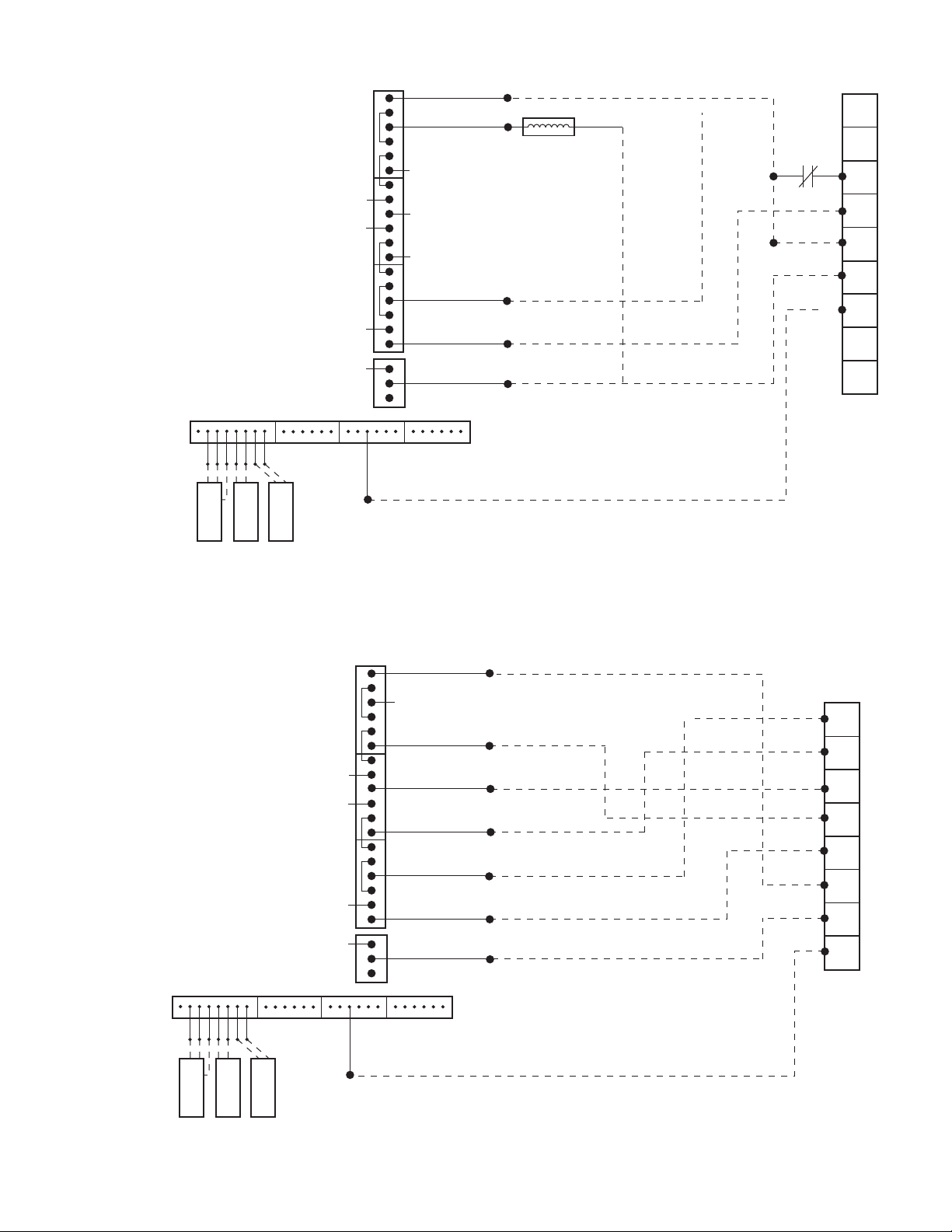
Fig. 30 — PremierLink Controller Applications with Deluxe D Control
LEGEND
NOTE: Reversing valve is on in Cooling
mode.
LWT — Leaving Water Temperature Sensor
SAT — Supply Air Temperature Sensor
SPT — Space Temperature Sensor
Fig. 29 — PremierLink™ Controller Applications with Complete C Control
15
Page 16

Table 3 — 50VQP Unit Electrical Data — Standard Unit
50VQP UNIT
SIZE
084 380/420-3-50 360/440
096 380/420-3-50 360/440 A,B,C 1 12.2 101.0 2.5 14.7 17.8 25
120 380/420-3-50 360/440
150 380/420-3-50 360/440
168 380/420-3-50 360/440 A,B,C 2 11.2 75.0 3.4 25.8 28.6 35
192 380/420-3-50 360/440 A,B,C 2 12.2 101.0 4.9 29.3 32.3 40
240 380/420-3-50 360/440 A,B,C 2 16.7 111.0 7.8 41.2 45.4 60
300 380/420-3-50 360/440
FLA — Full Load Amps
HACR — Heating, Air Conditioning, and Refrigeration
LRA — Locked Rotor Amps
MCA — Minimum Circuit Amps
RLA — Rated Load Amps
VOLTAGE
(V-Ph-Hz)
LEGEND NOTES:
MIN/MAX
VOLTAGE
BLOWER
OPTION
A,B,C 1 11.2 75.0 1.8 13.0 15.8 25
E 1 11.2 75.0 2.5 13.7 16.5 25
A,B,C 1 16.7 111.0 3.6 20.3 24.5 40
E 1 16.7 111.0 4.9 21.6 25.8 40
A,B,C 1 18.6 118.0 4.9 23.5 28.2 45
E 1 18.6 118.0 7.8 26.4 31.1 45
A,B,C 2 18.6 118.0 7.8 45.0 49.7 60
E 2 18.6 118.0 12.2 49.4 54.0 70
COMPRESSOR FAN
qty RLA LRA
1. HACR circuit breaker in U.S.A. only.
2. All fuses Class RK-5.
MOTOR
FLA
TOTAL UN IT
FLA
MCA
MAX FUSE/
Table 4 — 50VQP Unit Electrical Data — Dual Point Power Unit
50VQP
UNIT
SIZE
084 380/420-3-50 360/440
096 380/420-3-50 360/440 A,B,C 1 12.2 101.0 12.2 15.3 25 2.5 3.1 15
120 380/420-3-50 360/440
150 380/420-3-50 360/440
168 380/420-3-50 360/440 A,B,C 2 11.2 75.0 22.4 25.2 35 3.4 4.3 15
192 380/420-3-50 360/440 A,B,C 2 12.2 101.0 24.4 27.4 35 4.9 6.1 15
240 380/420-3-50 360/440 A,B,C 2 16.7 111.0 33.4 37.6 50 7.8 9.8 15
300 380/420-3-50 360/440
FLA — Full Load Amps
HACR — Heating, Air Conditioning, and Refrigeration
LRA — Locked Rotor Amps
MCA — Minimum Circuit Amps
RLA — Rated Load Amps
NOTES:
1. HACR circuit breaker in U.S.A. only.
2. All fuses Class RK-5.
VOLTAGE
(V-Ph-Hz)
MIN/MAX
VOLTAGE
LEGEND
BLOWER
OPTION
A,B,C 1 11.2 75.0 11.2 14.0 25 1.8 2.3 15
A,B,C 1 16.7 111.0 16.7 20.9 35 3.6 4.5 15
A,B,C 1 18.6 118.0 18.6 23.3 40 4.9 6.1 15
A,B,C 2 18.6 118.0 37.2 41.9 60 7.8 9.8 15
qty RLA LRA
E 1 11.2 75.0 11.2 14.0 25 2.5 3.1 15
E 1 16.7 111.0 16.7 20.9 35 4.9 6.1 15
E 1 18.6 118.0 18.6 23.3 40 7.8 9.8 15
E 2 18.6 118.0 37.2 41.9 60 12.2 15.3 25
COMPRESSOR EMERGENCY POWER SUPPLY
TOTAL
COMP FLA
COMP
MCA
COMP
MAX FUSE
FAN M OTOR
FLA
FAN
MCA
HACR
FAN
MAX FUSE
16
Page 17
Step 9 — Field Control Wiring
Fig. 31 — Low Voltage Field Wiring
COMPLETE C CONTROL
CAPACITOR
LINE
LOAD
COMPRESSOR CONTACTOR
TRANSFORMER
Y
GGGGR
W
O
Y2
Y1
G
R
C
Y2
Y1
G
O
W
C
R
DH
AL1
A
A
AL1
SW1
SW2
SW3
SW4
SW5
SW6
SW7
SW8
SW9
OFF
ON
G
DEHUM
CFM
TB1
J1
S1
THERMOSTAT CONNECTION
a50-8197
NOTE: Low voltage connector may be removed for
easy installation.
AQUAZONE CONTROL (Complete C Control Shown)
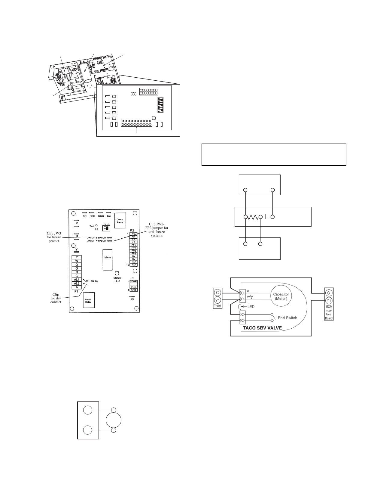
Fig. 32 — Typical Aquazone™ Control Board
Jumper Locations
a50-
6268tf.tif
TYPICAL
WATER
VALVE
C
A
24 VAC
TERMINAL STRIP P2
Fig. 33 — Typical Aquazone Accessory Wiring
(Control D Shown)
Fig. 35 — Taco SBV Valve Wiring
Fig. 34 — AMV Valve Wiring
a50-8441
a50-8442
THERMOSTAT CONNECTIONS — The thermostat should
be wired directly to the Aquazone™ control board. See
Fig. 27-31.
WATER FREEZE PROTECTION — The Aquazone control
allows the field selection of source fluid freeze protection
points through jumpers. The factory setting of jumper JW3
(FP1) is set for water at –1.1 C. In earth loop applications,
jumper JW3 should be clipped to change the setting to –12.2 C
when using antifreeze in colder earth loop applications. See
Fig. 32.
NOTE: The A terminal should only be used with 24 volt
signals — not line voltage signals.
WATER SOLENOID VALVES — An external solenoid
valve(s) should be used on ground water installations to shut
off flow to the unit when the compressor is not operating. A
slow closing valve may be required to help reduce water
hammer. Figure 33 shows typical wiring for a 24-vac external
solenoid valve. Figures 34 and 35 illustrate typical slow closing
water control valve wiring for Taco 500 Series and Taco ESP
Series valves. Slow closing valves take approximately 60 sec.
to open (very little water will flow before 45 sec.). Once fully
open, an end switch allows the compressor to be energized (only on valves with end switches). Only relay or triac based electronic thermostats should be used with slow closing valves.
When wired as shown, the slow closing valve will operate
properly with the following notations:
1. The valve will remain open during a unit lockout.
2. The valve will draw approximately 25 to 35 VA through
the “Y” signal of the thermostat.
IMPORTANT: Connecting a water solenoid valve can
overheat the anticipators of electromechanical thermostats. Only use relay based electronic thermostats.
C
1Y
AIR COIL FREEZE PROTECTION — The air coil freeze
protection jumper JW2 (FP2) is factory set for –1.1 C and
should not need adjusting.
ACCESSORY CONNECTIONS — Terminal labeled A on
the control is provided to control accessory devices such as
water valves, electronic air cleaners, humidifiers, etc. This
signal operates with the compressor terminal. See Fig. 33.
Refer to the specific unit wiring schematic for details.
1
HEATER SWITCH
C
2
1Y
AMV
3
TACO VALVE
THERMOSTAT
PRE-START-UP
System Checkout —
follow the system checkout procedure outlined below before
starting up the system. Be sure:
1. Voltage is within the utilization range specifications of the
unit compressor and fan motor and voltage is balanced
for 3-phase units.
2. Fuses, breakers and wire are correct size.
3. Low voltage wiring is complete.
4. Piping and system flushing is complete.
5. Air is purged from closed loop system.
6. System is balanced as required. Monitor if necessary.
7. Isolation valves are open.
8. Water control valves or loop pumps are wired.
17
When the installation is complete,
Page 18

9. Condensate line is open and correctly pitched.
10. Transformer switched to lower voltage tap if necessary.
11. Blower rotates freely — shipping support is removed.
12. Blower speed is on correct setting.
13. Air filter is clean and in position.
14. Service/access panels are in place.
15. Return-air temperature is 4.4 to 26.7 C for heating and
10.0 to 43.3 C for cooling.
16. Air coil is clean.
17. Control field-selected settings are correct.
AIR COIL — To obtain maximum performance, the air coil
should be cleaned before starting the unit. A 10% solution of
dishwasher detergent and water is recommended for both sides
of the coil. Rinse thoroughly with water.
Airflow and External Static Pressure — The
50VQP units are available with standard, low, and high-static
factory-installed options. These options will substitute a different blower drive sheave for each static range. In addition, certain static ranges may require the optional large fan motor.
SHEAVE ADJUSTMENT — The 50VQP units are supplied
with a variable sheave drive on the fan motor to adjust for differing airflows at various ESP (external static pressure) conditions. See Tables 5-12 for unit airflows. When fully closed, the
sheave will produce the highest static capability (higher rpm).
To adjust sheave position, follow the procedure outlined below:
1. Loosen belt tension and remove belt.
2. Loosen set screw on fan motor.
3. Open sheave to desired position.
4. Retighten set screw and replace belt.
NOTE: Set belt tension as outlined below.
BELT TENSION ADJUSTMENT — An overly loose belt
will, upon starting motor, produce a slippage “squeal” and
cause premature belt failure and or intermittent airflow. An
overly tight belt can cause premature motor or blower bearing failure. To adjust the belt tension, follow the procedure
outlined below:
1. Remove belt from motor sheave.
2. Lift motor assembly.
3. Loosen the
5
/16-in. hex nuts on the grommet motor adjustment bolts (2 per bolt). To increase the belt tension loosen
the top hex nut. To decrease the belt tension loosen the
bottom hex nut.
4. Turn the bolts by hand to the desired position then tighten
5
the
/16-in. hex nuts (2 per bolt).
5. Lower the motor assembly.
6. Install the belt.
7. The belt tension can be adjusted by using one of the following methods:
a. Tighten until belt deflects approximately 13 mm
with very firm finger pressure.
b. Grasp belt midway between two pulleys and twist
for a 90-degreerotation.
NOTE: Adjusting less than 90 degrees will over-
tighten the belt and adjusting more than 90degrees
will loosen belt.
c. Set proper belt tension to 32 to 36 kg.
NOTE: The motor position should not need adjustment. Motor
sheave position is at mid position of each sheave. For example,
the motor sheave is 2.5 turns open on a 5-turn sheave. The belt
tension adjustment can also be accomplished by turning the
5
/16-in. hex nuts to the desired position.
NOTE: Available airflows for all units are shown in
Tables 5-12.
18
Page 19

755.2
802.4
849.6
896.8
944.0
991.2
1038.4
1085.6
1132.8
1180.0
1227.2
1274.4
1321.6
1368.8
1416.0
Table 5 — 50VQP084 Blower Performance Data
AIRFLOW
(l/s)
BkW — — 0.12 0.15 0.13 0.19 0.22 0.24 0.26 0.30 0.31 0.33 0.37 0.39 — —
Sheave/Mtr ——BBAAAACCCCCC——
RPM — — 388 437 482 527 564 599 630 663 690 716 744 767 — —
Turns Open — — 3.5 1.5 5 3.5 2.5 1.5 5.5 4.5 3.5 2.5 2 1 — —
BkW — — 0.13 0.16 0.15 0.20 0.24 0.25 0.28 0.32 0.34 0.36 0.40 0.42 — —
Sheave/Mtr ——BBAAAACCCCCC——
RPM — — 392 440 485 529 566 601 633 666 693 720 747 771 — —
Turns Open —— 31.553.521.55.54.532.52 1 ——
BkW — — 0.14 0.17 0.17 0.22 0.25 0.27 0.29 0.33 0.36 0.38 0.42 — — —
Sheave/Mtr —— B B A A A A C C C C C ———
RPM — — 395 444 488 530 568 603 636 668 697 723 751 — — —
Turns Open ——2.51 5 3.52 1 5 4 3 21.5———
BkW — — 0.15 0.18 0.19 0.23 0.27 0.28 0.31 0.35 0.38 0.41 0.45 — — —
Sheave/Mtr —— B B A A A C C C C C C ———
RPM — — 399 447 491 532 571 606 639 671 700 727 754 — — —
Turns Open — — 2.5 1 4.5 3 2 5.5 5 4 3 2 1.5 — — —
BkW — 0.11 0.16 0.19 0.21 0.25 0.28 0.30 0.33 0.37 0.40 0.43 0.47 — — —
Sheave/Mtr — B B A A A A C C C C C C ———
RPM — 352 403 450 493 534 573 608 641 673 703 730 757 — — —
Turns Open — 4.5 2.5 5.5 4.5 3 2 5.5 4.5 4 2.5 2 1.5 — — —
BkW — 0.12 0.18 0.22 0.25 0.28 0.31 0.33 0.37 0.40 0.44 0.48 0.52 — — —
Sheave/Mtr — B B A A A A C C C C C C ———
RPM — 362 410 457 499 537 577 612 647 678 710 737 764 — — —
Turns Open — 4.5 2 5.5 4.5 3 1.5 5.5 4.5 3.5 2.5 1.5 1 — — —
BkW — 0.17 0.21 0.24 0.25 0.29 0.33 0.37 0.40 0.44 0.48 0.52 0.55 — — —
Sheave/Mtr — B B A A A A C C C C C C ———
RPM — 375 424 467 507 548 584 621 653 684 716 743 772 — — —
Turns Open — 4 2 5 42.51.554.53.52.51.51 ———
BkW —0.180.220.250.290.330.370.400.440.480.520.55————
Sheave/Mtr — B B A A A A C C C C C ————
RPM —387435476518555590627659692721751————
Turns Open —3.51.55 42.51.55 4 3 21.5————
BkW 0.180.220.250.290.330.370.400.440.480.520.550.59————
Sheave/Mtr B B B A A A A C C C C C————
RPM 353403446485527563600633665697726756————
Turns Open 4..531.54.53.52.51 5 4 3 21.5————
BkW 0.210.230.250.290.330.370.400.440.480.550.590.63————
Sheave/Mtr B B B A A A A C C C C C————
RPM 362411452495532567604636670700729759————
Turns Open 4 2.514.53.52 14.54 3 2 1 ————
BkW 0.220.250.320.360.400.430.470.510.550.580.620.66————
Sheave/Mtr B B A A A A C C C C C C ————
RPM 377420460500536570606638671701729759————
Turns Open 3.525.54 3 25.54.53.52.5 2 1 ————
BkW 0.250.280.320.360.400.440.480.520.550.590.630.67————
Sheave/Mtr B B A A A A C C C C C C ————
RPM 381423463504539576609641674703734762————
Turns Open 3.525.54 31.55.54.53.52.51.51 ————
BkW 0.250.290.330.370.400.480.520.550.590.630.670.70————
Sheave/Mtr B B A A A A C C C C C C ————
RPM 390431474510545581613647677706737764————
Turns Open 3 1.553.52.51.55.543.52.51.51 ————
BkW 0.290.330.370.400.440.480.550.590.630.670.700.78————
Sheave/Mtr B B A A A A C C C C C E ————
RPM 399440481517551586618651681710740767————
Turns Open 2.51.553.5 2 1 5 4 3 21.51 ————
BkW 0.320.370.400.440.480.520.550.630.670.700.780.82————
Sheave/Mtr B B A A A A C C C C E E ————
RPM 412455492526563595628658687718745774————
Turns Open 2.514.53 2 1 5 4 3 21.51 ————
0 25 50 75 100 125 150 175 200 225 250 275 300 325 350 375
EXTERNAL STATIC PRESSURE (Pa)
A—Standard rpm/Standard Motor
B—Low rpm/Standard Motor
bhp — Brake Horsepower
C—High r pm/Standard Motor
E—High rpm/Large Motor
ESP — Exter nal Static Pressure
LEGEND NOTES:
1. Unit is factory shipped with standard static sheave and drive at 2.5 turns open.
Other speeds require field selection.
2. For applications requiring higher static pressures, contact your local Carrier representative. Performance data does not include drive losses and is based on sea
level conditions.
3. All airflow is rated at lowest voltage. If unit is dual voltage rated, data is based on
lowest voltage.
4. A = Standard Rpm/Standard Motor, B = Low Rpm/Standard Motor, C = High
Rpm/Standard Motor, E = High Rpm/Large Motor.
19
Page 20

AIRFLOW
(l/s)
0 25 50 75 100 125 150 175 200 225 250 275 300 325 350 375
BkW — 0.100.140.170.170.220.250.270.290.330.360.380.42 — — —
849.6
Sheave/Mtr —BBAAAAACCCCC———
RPM — 343 395 444 488 530 568 603 636 668 697 723 751 — — —
Turns Open —53653.52.51.55432.51.5———
BkW — 0.110.150.180.190.230.270.280.310.350.380.410.45 — — —
896.8
Sheave/Mtr —BBAAAAACCCCC———
RPM — 348 399 447 491 532 571 606 639 671 700 727 754 — — —
Turns Open —4.53653.521.55432.51.5———
BkW — 0.110.160.190.210.250.280.300.330.370.400.430.47 — — —
944.0
Sheave/Mtr —BBAAAAACCCCC———
RPM — 352 403 450 493 534 573 608 641 673 703 730 757 — — —
Turns Open —4.535.54.5321542.521.5———
BkW — 0.120.180.220.250.280.310.330.370.400.440.480.52 — — —
991.2
Sheave/Mtr —BBAAAAACCCCC———
RPM — 362 410 457 499 537 577 612 647 678 710 737 764 — — —
Turns Open — 4 2.5 5.5 4.5 3 2 1 4.5 3.5 2.5 2 1 — — —
BkW — 0.170.210.240.250.290.330.370.400.440.480.520.55 — — —
1038.4
Sheave/Mtr —BBAAAAACCCCC———
RPM — 375 424 467 507 548 584 621 653 684 716 743 772 — — —
Turns Open — 4 2 5 4.5 3 1.5 1 4.5 3.5 2.5 2 1 — — —
BkW 0.16 0.18 0.22 0.25 0.29 0.33 0.37 0.40 0.44 0.48 0.52 0.55 — — — —
1085.6
Sheave/Mtr BBAAAAACCCCC————
RPM 339 387 435 476 518 555 590 627 659 692 721 751 — — — —
Turns Open 5 3.5 6 5 4 2.5 1.5 5.5 4.5 3 2.5 1.5 — — — —
BkW 0.18 0.22 0.25 0.29 0.33 0.37 0.40 0.44 0.48 0.52 0.55 0.59 — — — —
1132.8
Sheave/Mtr BBAAAAACCCCC————
RPM 353 403 446 485 527 563 600 633 665 697 726 756 — — — —
Turns Open 4.53653.52.51.55.54321.5————
BkW 0.21 0.23 0.25 0.29 0.33 0.37 0.40 0.44 0.48 0.55 0.59 0.63 — — — —
1180.0
Sheave/Mtr BBAAAAACCCCC————
RPM 362 411 452 495 532 567 604 636 670 700 729 759 — — — —
Turns Open 4.02.55.54.53.52154321————
BkW 0.22 0.25 0.32 0.36 0.40 0.43 0.47 0.51 0.55 0.58 0.62 0.66 — — — —
1227.2
Sheave/Mtr BBAAAAACCCCC————
RPM 377 420 460 500 536 570 606 638 671 701 729 759 — — — —
Turns Open 3.525.54.53 2 1 53.52.52 1 ————
BkW 0.25 0.28 0.32 0.36 0.40 0.44 0.48 0.52 0.55 0.59 0.63 0.67 — — — —
1274.4
Sheave/Mtr BBAAAAACCCCC————
RPM 381 423 463 504 539 576 609 641 674 703 734 762 — — — —
Turns Open 3.525431.5153.52.521————
1321.6
BkW
Sheave/Mtr BBAAAAACCCC—————
RPM 390 431 474 510 545 581 613 647 677 706 737 — — — — —
0.25 0.29 0.33 0.37 0.40 0.48 0.52 0.55 0.59 0.63 0.67 — — — — —
Turns Open 325431.514.53.52.52—————
BkW 0.29 0.33 0.37 0.40 0.44 0.48 0.55 0.59 0.63 0.67 0.70 — — — — —
1368.8
Sheave/Mtr BAAAAACCCCC—————
RPM 399 440 481 517 551 586 618 651 681 710 740 — — — — —
Turns Open 3 6 4.5 3.5 2.5 1.5 5.5 4.5 3 2.5 1.5 — — — — —
A—Standard rpm/Standard Motor
B—Low rpm/Standard Motor
bhp — Brake Horsepower
C—High rpm/Standard Motor
ESP — External Static Pressure
LEGEND NOTES:
Table 6 — 50VQP096 Blower Performance Data
EXTERNAL STATIC PRESSURE (Pa)
1. Unit is factory shipped with standard static sheave and drive at 2.5 turns open. Other
speeds require field selection.
2. For applications requiring higher static pressures, contact your local Carrier representative. Performance data does not include drive losses and is based on sea level
conditions.
3. All airflow is rated at lowest voltage. If unit is dual voltage rated, data is based on
lowest voltage.
4. A = Standard Rpm/Standard Motor, B = Low Rpm/Standard Motor, C = High
Rpm/Standard Motor.
20
Page 21

AIRFLOW
(l/s)
0 25 50 75 100 125 150 175 200 225 250 275 300 325 350 375
BkW 0.32 0.37 0.40 0.44 0.48 0.52 0.55 0.63 0.67 0.70 0.78 — — — — —
1416.0
Sheave/Mtr BAAAAACCCCC—————
RPM 412 455 492 526 563 595 628 658 687 718 745 — — — — —
Turns Open 2.55.54.53.52154321.5—————
BkW 0.33 0.40 0.44 0.48 0.52 0.55 0.63 0.67 0.70 0.74 0.78 — — — — —
1463.2
Sheave/Mtr BAAAAACCCCC—————
RPM 421 459 499 533 569 600 633 663 691 722 749 — — — — —
Turns Open 25.5432154321.5—————
BkW 0.37 0.40 0.48 0.52 0.55 0.63 0.67 0.70 0.74 0.78 0.85 — — — — —
1510.4
Sheave/Mtr AAAAAACCCCC—————
RPM 441 478 513 549 581 614 644 672 703 730 759 — — — — —
Turns Open 6 5 42.51.514.53.52.521.5—————
BkW 0.40 0.48 0.52 0.55 0.62 0.67 0.70 0.74 0.78 0.85 0.92 — — — — —
1557.6
Sheave/Mtr A A A A A C C C C C C —————
RPM 456 495 529 561 595 625 656 685 712 741 767 — — — — —
Turns Open 5.54.53.52 15.54 32.52 1 —————
BkW 0.47 0.52 0.55 0.59 0.63 0.70 0.74 0.78 0.85 0.89 0.93 — — — — —
1604.8
Sheave/Mtr A A A A A C C C C C C —————
RPM 471 506 539 574 604 633 664 692 721 747 773 — — — — —
Turns Open 5.54 31.51 5 4 3 21.51 —————
BkW 0.48 0.55 0.59 0.63 0.70 0.74 0.78 0.85 0.92 0.96 — — — — — —
1652.0
Sheave/Mtr A A A A C C C C C C ——————
RPM 486 520 555 586 615 647 674 704 730 756 — — — — — —
Turns Open 53.52.515.54.54 3 21.5——————
A—Standard rpm/Standard Motor
B—Low rpm/Standard Motor
bhp — Brake Horsepower
C—High rpm/Standard Motor
ESP — External Static Pressure
LEGEND NOTES:
Table 6 — 50VQP096 Blower Performance Data (cont)
EXTERNAL STATIC PRESSURE (Pa)
1. Unit is factory shipped with standard static sheave and drive at 2.5 turns open. Other
speeds require field selection.
2. For applications requiring higher static pressures, contact your local Carrier representative. Performance data does not include drive losses and is based on sea level
conditions.
3. All airflow is rated at lowest voltage. If unit is dual voltage rated, data is based on
lowest voltage.
4. A = Standard Rpm/Standard Motor, B = Low Rpm/Standard Motor, C = High
Rpm/Standard Motor.
21
Page 22

AIRFLOW
(l/s)
0 25 50 75 100 125 150 175 200 225 250 275 300 325 350 375
BkW — — 0.18 0.19 0.22 0.27 0.30 0.34 0.37 0.42 0.45 0.48 0.52 0.55 0.60 0.63
1085.6
Sheave/Mtr ——BBBAAAAAACCCCC
RPM — — 376 423 466 503 543 580 616 649 682 712 742 770 797 822
Turns Open ——64.536543215.54.5432.5
BkW — — 0.19 0.22 0.27 0.30 0.34 0.37 0.42 0.45 0.52 0.52 0.57 0.60 0.67 0.70
1132.8
Sheave/Mtr ——BBBAAAAACCCCCC
RPM — — 395 439 481 517 555 592 626 659 691 722 751 779 805 831
Turns Open — — 5.5 4 2.55.54.53.52.51.5 6 5.54.53.5 3 2
BkW — — 0.22 0.25 0.30 0.33 0.37 0.40 0.45 0.48 0.55 0.60 0.63 0.67 0.70 0.75
1180.0
Sheave/Mtr ——BBBAAAAACCCCCC
RPM — — 412 455 496 530 567 603 637 669 701 730 759 787 813 839
Turns Open ——531.55.543216543.52.51.5
BkW — 0.220.250.300.330.370.400.450.480.550.600.630.670.700.750.78
1227.2
Sheave/Mtr —BBBAAAAAACCCCCC
RPM — 385 430 471 506 544 579 614 647 679 710 739 768 795 822 847
Turns Open — 6 4 2.5 6 5 3.5 2.5 1.5 1 5.5 4.5 4 3 2 1.5
BkW — 0.250.300.330.370.400.450.480.550.600.630.670.700.750.780.82
1274.4
Sheave/Mtr —BBBAAAAACCCCCCC
RPM — 403 446 486 520 556 591 625 657 689 719 748 776 803 830 855
Turns Open — 5 3.5 2 5.5 4.5 3.5 2.5 1 6 5.5 4.5 3.5 3 2 1
BkW 0.25 0.30 0.33 0.37 0.40 0.45 0.48 0.52 0.60 0.63 0.67 0.70 0.75 0.78 0.82 0.90
1321.6
Sheave/Mtr BBBAAAAAACCCCCCC
RPM 377 421 462 501 534 569 603 636 668 698 728 757 785 812 838 860
Turns Open 64.536543216543.52.51.51
BkW 0.30 0.33 0.37 0.40 0.45 0.48 0.52 0.55 0.63 0.67 0.70 0.75 0.78 0.85 0.90 0.93
1368.8
Sheave/Mtr BBBAAAAAACCCCCCC
RPM 395 438 478 515 547 582 615 647 678 708 737 765 793 819 845 868
Turns Open 5.5 4 2.5 6 4.5 3.5 2.5 1.5 1 5.5 5 4 3 2.5 1.5 0.5
BkW 0.33 0.37 0.40 0.44 0.48 0.52 0.55 0.63 0.67 0.70 0.78 0.82 0.85 0.89 0.93 1.00
1416.0
Sheave/Mtr BBBAAAAACCCCCCCC
RPM 414 453 491 529 563 595 626 659 689 717 745 774 801 826 851 877
Turns Open 4.5 3.5 2 5.5 4.5 3.5 2.5 1.5 6 5.5 4.5 3.5 3 2 1 0.5
BkW 0.37 0.40 0.44 0.48 0.52 0.55 0.63 0.67 0.70 0.78 0.82 0.85 0.89 0.93 1.00 1.08
1463.2
Sheave/Mtr BBAAAAAACCCCCCCC
RPM 431 469 504 542 575 607 637 670 699 726 754 783 809 834 859 884
Turns Open 43654321654.53.52.5210.5
BkW 0.40 0.44 0.48 0.52 0.55 0.63 0.67 0.70 0.78 0.82 0.85 0.93 0.96 1.00 1.08 1.14
1510.4
Sheave/Mtr BBAAAAAACCCCCCCC
RPM
448 485 520 556 588 619 649 680 708 736 765 791 817 841 868 891
Turns Open 3.5 2 5.54.53.52.51.5 1 5.5 5 4 3 2.51.50.5 0
BkW 0.44 0.48 0.52 0.55 0.63 0.67 0.70 0.78 0.82 0.85 0.93 0.96 1.00 1.08 1.11 1.15
1557.6
Sheave/Mtr BBAAAAACCCCCCCCC
RPM 464 500 537 570 601 631 662 691 718 745 774 799 824 849 875 898
Turns Open 31.554321.565.54.54321.50.50
BkW 0.48 0.52 0.55 0.63 0.67 0.70 0.78 0.82 0.85 0.93 0.96 1.00 1.08 1.11 1.15 —
1604.8
Sheave/Mtr BAAAAAACCCCCCCC—
RPM 480 515 551 583 613 642 674 701 728 754 783 808 833 857 882 —
Turns Open 2.5 6 4.5 3.5 3 2 1 6 5 4.5 3.5 2.5 2 1 0 —
BkW 0.52 0.55 0.63 0.67 0.70 0.78 0.82 0.85 0.93 0.96 1.00 1.08 1.15 1.19 1.23 —
1652.0
Sheave/Mtr BAAAAACCCCCCCCC—
RPM 496 530 565 596 625 654 684 711 738 766 792 816 841 867 890 —
Turns Open 25.543.52.51.565.54.54 32.51.51 0 —
A—Standard rpm/Standard Motor
B—Low rpm/Standard Motor
bhp — Brake Horsepower
C—High r pm/Standard Motor
E—High rpm/Large Motor
ESP — Exter nal Static Pressure
LEGEND NOTES:
Table 7 — 50VQP120 Blower Performance Data
EXTERNAL STATIC PRESSURE (Pa)
1. Unit is factory shipped with standard static sheave and drive at 2.5 turns open.
Other speeds require field selection.
2. For applications requiring higher static pressures, contact your local Carrier representative. Performance data does not include drive losses and is based on sea
level conditions.
3. All airflow is rated at lowest voltage. If unit is dual voltage rated, data is based on
lowest voltage.
4. A = Standard Rpm/Standard Motor, B = Low Rpm/Standard Motor, C = High
Rpm/Standard Motor, E = High Rpm/Large Motor.
22
Page 23

AIRFLOW
(l/s)
0 25 50 75 100 125 150 175 200 225 250 275 300 325 350 375
BkW 0.55 0.63 0.67 0.70 0.78 0.82 0.85 0.93 1.00 1.04 1.08 1.15 1.19 1.23 1.30 —
1699.2
Sheave/Mtr AAAAAACCCCCCCCC—
RPM 511 544 578 608 637 668 695 722 748 776 800 825 849 874 897 —
Turns Open 653.5321654.53.5321.50.50—
BkW 0.63 0.67 0.70 0.78 0.85 0.89 0.93 1.00 1.04 1.08 1.15 1.23 1.26 1.30 — —
1746.4
Sheave/Mtr AAAAAACCCCCCCC——
RPM 526 561 592 621 649 679 706 732 758 785 809 833 857 882 — —
Turns Open 5.5 4.5 3.5 2.5 1.5 1 5.5 5 4 3.5 2.5 2 1 0.5 — —
BkW 0.67 0.70 0.78 0.82 0.85 0.93 1.00 1.04 1.08 1.15 1.23 1.26 1.30 1.38 — —
1793.6
Sheave/Mtr AAAAACCCCCCCCC——
RPM 544 575 605 633 661 691 717 742 767 794 818 842 867 890 — —
Turns Open 5432165.54.54321.50.50——
BkW 0.70 0.78 0.85 0.89 0.93 1.00 1.08 1.11 1.15 1.23 1.30 1.34 1.38 1.45 — —
1840.8
Sheave/Mtr AAAAACCCCCCCCE——
RPM 555 589 618 646 676 702 728 753 779 803 827 850 875 898 — —
Turns Open 4.5 3.5 2.5 1.5 6 6 5 4 3.5 2.5 2 1 0.5 0 — —
BkW 0.78 0.82 0.85 0.93 1.00 1.08 1.11 1.15 1.23 1.30 1.34 1.38 1.50 1.53 — —
1888.0
Sheave/Mtr A AA ACCCCCCCCEE——
RPM 572 601 630 657 686 712 737 762 789 812 836 859 883 905 — —
Turns Open 432165.54.5432.51.5100——
BkW 0.85 0.89 0.93 1.00 1.08 1.11 1.15 1.23 1.30 1.38 1.41 1.50 1.53 — — —
1935.2
Sheave/Mtr A AA ACCCCCCCEE———
RPM 589 617 645 672 700 726 751 775 801 824 847 872 894 — — —
Turns Open 3.5 2.5 1.5 1 6 5 4.5 3.5 2.5 2 1 0.5 0 — — —
BkW 0.93 0.96 1.00 1.08 1.15 1.19 1.23 1.30 1.38 1.50 1.53 1.56 — — — —
1982.4
Sheave/Mtr A AACCCCCC EEE————
RPM 605 633 660 689 714 739 763 790 813 836 858 882 — — — —
Turns Open 32165.54.54321.510.5————
BkW 0.96 1.00 1.08 1.15 1.23 1.26 1.30 1.38 1.50 1.53 1.60 1.68 — — — —
2029.6
Sheave/Mtr A AACCCCC EEEE————
RPM 621 649 675 703 728 752 776 802 827 847 869 893 — — — —
Turns Open 2.51.516543.52.521.510————
BkW 1.0401.081.151.231.301.381.411.501.531.601.681.75 — — — —
2076.8
Sheave/Mtr A ACCCCCEC EEE————
RPM 637 664 690 717 742 766 791 814 836 858 882 904 — — — —
Turns Open 2165.54.5432210.50————
BkW 1.11 1.15 1.23 1.30 1.38 1.45 1.53 1.56 1.60 1.68 1.75 — — — — —
2124.0
Sheave/Mtr A ACCCCE ECEE—————
RPM 653 679 707 731 755 779 804 826 848 870 893 — — — — —
Turns Open 1.515.55 43.53 21.51 0 —————
BkW 0.96 1.00 1.08 1.15 1.23 1.26 1.30 1.38 1.50 1.53 1.60 1.68 — — — —
2029.6
Sheave/Mtr A AACCCCC EEEE————
RPM 621 649 675 703 728 752 776 802 827 847 869 893 — — — —
Turns Open 2.51.516543.52.521.510————
A—Standard rpm/Standard Motor
B—Low rpm/Standard Motor
bhp — Brake Horsepower
C—High r pm/Standard Motor
E—High rpm/Large Motor
ESP — Exter nal Static Pressure
LEGEND NOTES:
Table 7 — 50VQP120 Blower Performance Data (cont)
EXTERNAL STATIC PRESSURE (Pa)
1. Unit is factory shipped with standard static sheave and drive at 2.5 turns open.
Other speeds require field selection.
2. For applications requiring higher static pressures, contact your local Carrier representative. Performance data does not include drive losses and is based on sea
level conditions.
3. All airflow is rated at lowest voltage. If unit is dual voltage rated, data is based on
lowest voltage.
4. A = Standard Rpm/Standard Motor, B = Low Rpm/Standard Motor, C = High
Rpm/Standard Motor, E = High Rpm/Large Motor.
23
Page 24

AIRFLOW
(l/s)
0 25 50 75 100 125 150 175 200 225 250 275 300 325 350 375
BkW —————0.340.370.420.490.520.570.640.720.790.870.94
1321.6
Sheave/Mtr ————— BBAAAAAACCC
RPM —————533572606640676712746783821859901
Turns Open —————5.546543215.54.53
BkW —————0.370.420.450.520.570.600.670.750.810.900.97
1368.8
Sheave/Mtr ————— BBAAAAAACCC
RPM —————544582619652686719754789823860902
Turns Open ————— 5 45.54.53.52.51.515.54 3
BkW ————0.370.420.450.520.570.600.670.750.790.820.941.02
1416.0
Sheave/Mtr ———— BBBAAAAACCCC
RPM ————521558595628663697728762796828863903
Turns Open ———— 64.53.55.54.53.52.51.56 5 4 3
BkW ————0.420.450.520.550.600.640.720.780.820.900.971.05
1463.2
Sheave/Mtr ———— BBAAAAAACCCC
RPM ————536572608640674705737769799832866904
Turns Open ————5.54 6543216543
BkW ————0.450.490.550.600.670.700.750.850.900.971.051.12
1510.4
Sheave/Mtr ———— BBAAAAAACCCC
RPM ————548585618652685715747778807836868905
Turns Open ———— 53.55.54.53.52.51.515.553.53
BkW — — — 0.45 0.48 0.52 0.60 0.64 0.70 0.78 0.82 0.90 0.93 1.00 1.08 1.15
1557.6
Sheave/Mtr ———BBAAAAAAACCCC
RPM — — — 522 562 599 631 664 694 725 756 784 815 845 874 906
Turns Open ———64.565.54 32.51.515.54.53.53
BkW — — — 0.48 0.52 0.57 0.63 0.67 0.75 0.82 0.85 0.93 1.00 1.08 1.15 1.20
1604.8
Sheave/Mtr ———BBAAAAAACCCCC
RPM — — — 537 576 612 643 676 705 736 763 793 823 850 880 908
Turns Open ———5.545.554321654.53.52.5
BkW — — — 0.52 0.57 0.60 0.67 0.75 0.78 0.85 0.93 1.00 1.05 1.12 1.20 1.23
1652.0
Sheave/Mtr ———BBAAAAAACCCCC
RPM — — — 551 589 622 655 685 716 746 776 802 829 858 886 913
Turns Open ———53.55.54.53.52.52165432.5
BkW — — 0.52 0.55 0.60 0.67 0.75 0.78 0.85 0.93 0.97 1.05 1.08 1.15 1.23 1.30
1699.2
Sheave/Mtr ——BBAAAAAACCCCCC
RPM — — 526 565 600 634 665 696 727 754 783 809 837 865 891 919
Turns Open ——64.5654321.565.54.5432.5
1746.4
BkW
Sheave/Mtr ——BBAAAAAACCCCCC
RPM — — 541 579 613 647 677 707 737 764 793 818 846 871 898 926
— — 0.55 0.63 0.67 0.70 0.78 0.85 0.93 0.97 1.00 1.08 1.15 1.23 1.30 1.38
Turns Open ——5.545.54.54321.565.54.53.532
BkW — 0.550.630.670.700.780.850.930.961.001.081.151.231.301.381.45
1793.6
Sheave/Mtr —BBBAAAAAACCCCCC
RPM — 519 554 591 626 659 688 718 746 774 802 829 855 879 905 931
Turns Open — 6 5 3.55.54.53.52.5 2 1 5.5 5 4.53.52.5 2
BkW — 0.590.630.700.780.850.890.931.001.081.151.231.301.381.451.52
1840.8
Sheave/Mtr —BBAAAAAAACCCCCC
RPM — 531 569 605 639 669 702 729 757 785 811 838 862 887 913 938
Turns Open — 5.5 4.5 6 5 4 3 2.5 1.5 1 5.5 5 4 3.5 2.5 2
BkW — 0.630.700.780.850.890.931.001.081.151.231.261.301.381.451.53
1888.0
Sheave/Mtr —BBAAAAAACCCCCCC
RPM — 545 582 618 651 683 710 739 767 794 821 845 870 895 920 945
Turns Open — 5 45.54.54 3 21.565.54.54 32.52
BkW 0.63 0.70 0.78 0.82 0.85 0.93 1.00 1.08 1.15 1.23 1.26 1.30 1.38 1.45 1.53 1.60
1935.2
Sheave/Mtr BBBAAAAAACCCCCCC
RPM 523 560 596 631 661 692 722 750 778 804 831 854 879 904 928 951
Turns Open 6 4.5 3.5 5.5 4.5 3.5 2.5 1.5 1 6 5 4.5 3.5 3 2 1.5
A—Standard rpm/Standard Motor
B—Low rpm/Standard Motor
bhp — Brake Horsepower
C—High r pm/Standard Motor
E—High rpm/Large Motor
ESP — Exter nal Static Pressure
LEGEND NOTES:
Table 8 — 50VQP150 Blower Performance Data
EXTERNAL STATIC PRESSURE (Pa)
1. Unit is factory shipped with standard static sheave and drive at 2.5 turns open.
Other speeds require field selection.
2. For applications requiring higher static pressures, contact your local Carrier representative. Performance data does not include drive losses and is based on sea
level conditions.
3. All airflow is rated at lowest voltage. If unit is dual voltage rated, data is based on
lowest voltage.
4. A = Standard Rpm/Standard Motor, B = Low Rpm/Standard Motor, C = High
Rpm/Standard Motor, E = High Rpm/Large Motor.
24
Page 25

AIRFLOW
(l/s)
0 25 50 75 100 125 150 175 200 225 250 275 300 325 350 375
BkW 0.70 0.74 0.78 0.85 0.93 1.00 1.08 1.15 1.19 1.23 1.30 1.38 1.45 1.53 1.60 1.68
1982.4
Sheave/Mtr BBAAAAAAACCCCCCC
RPM 538 574 609 640 673 703 733 761 788 812 838 863 888 912 934 958
Turns Open 5.54654321.515.5543.52.521.5
BkW 0.70 0.78 0.85 0.93 1.00 1.08 1.15 1.19 1.23 1.30 1.38 1.45 1.53 1.60 1.68 1.75
2029.6
Sheave/Mtr BBAAAAAACCCCCCCC
RPM 553 588 620 653 685 715 744 771 796 822 847 872 896 919 942 966
Turns Open 5 3.5 5.5 4.5 3.5 2.5 2 1 6 5.5 4.5 4 3 2.5 1.5 1
BkW 0.78 0.85 0.93 1.00 1.08 1.15 1.19 1.23 1.30 1.38 1.45 1.53 1.60 1.68 1.75 1.83
2076.8
Sheave/Mtr BBAAAAAACCCCCCCC
RPM 568 602 633 666 697 726 755 782 806 832 857 881 904 927 950 973
Turns Open 4.5 3 5 4 3.5 2.5 1.5 1 6 5 4.5 3.5 3 2 1.5 1
BkW 0.85 0.90 0.97 1.05 1.12 1.20 1.27 1.35 1.42 1.50 1.57 1.65 1.72 1.80 1.87 —
2124.0
Sheave/Mtr BAAAAAACCCCCCCC—
RPM 581 613 646 678 706 735 763 791 817 842 867 889 912 935 958 —
Turns Open 4 6 4.5 4 3 2 1.5 6 5.5 4.5 4 3 2.5 2 1.5 —
BkW 0.89 0.93 1.00 1.08 1.15 1.23 1.30 1.38 1.45 1.53 1.60 1.68 1.75 1.83 1.90 —
2171.2
Sheave/Mtr BAAAAAACCCCCCCC—
RPM 598 623 656 687 715 744 772 799 825 850 872 896 919 942 963 —
Turns Open 3.5 5.5 4.5 3.5 2.5 2 1 6 5.5 4.5 3.5 3 2 1.5 1 —
BkW 0.93 1.00 1.08 1.15 1.23 1.30 1.38 1.45 1.53 1.60 1.68 1.75 1.83 1.90 1.97 —
2218.4
Sheave/Mtr AAAAAAACCCCCCCC—
RPM 605 637 666 697 727 755 783 809 835 858 882 905 928 951 973 —
Turns Open 65432.51.515.5543.52.521.51—
BkW 1.00 1.08 1.15 1.23 1.30 1.38 1.45 1.53 1.60 1.68 1.75 1.83 1.90 1.97 2.05 —
2265.6
Sheave/Mtr AAAAAACCCCCCCCC—
RPM 618 647 678 708 738 766 793 819 844 867 891 914 937 959 980 —
Turns Open 5.54.5432165.54.5432.51.51.51—
BkW 1.08 1.15 1.23 1.30 1.38 1.45 1.53 1.60 1.68 1.75 1.83 1.90 1.97 2.05 2.12 —
2312.8
Sheave/Mtr AAAAAACCCCCCCCC—
RPM 631 662 690 720 749 777 803 827 852 877 900 923 946 966 988 —
Turns Open 5.5 4 3.5 2.5 1.5 1 6 5 4.5 3.5 3 2 1.5 1 1 —
BkW 1.15 1.23 1.30 1.38 1.45 1.53 1.60 1.68 1.75 1.83 1.90 1.97 2.05 2.12 — —
2360.0
Sheave/Mtr AAAAACCCCCCCCC——
RPM 642 672 702 731 760 785 811 837 862 886 909 932 953 975 — —
Turns Open 54321.565.54.5432.51.511——
BkW 1.23 1.30 1.38 1.45 1.53 1.60 1.68 1.75 1.83 1.90 1.97 2.05 2.12 — — —
2407.2
Sheave/Mtr AAAAACCCCCCCC———
RPM
655 685 714 743 769 798 822 847 872 896 917 940 962 — — —
Turns Open 4.5 3.5 2.5 1.5 1 6 5 4.5 3.5 3 2.5 1.5 1 — — —
BkW 1.30 1.38 1.45 1.53 1.60 1.68 1.75 1.83 1.90 1.97 2.05 2.12 2.24 — — —
2454.4
Sheave/Mtr A AA ACCCCCCCCE———
RPM 668 697 726 752 782 806 832 857 882 903 926 949 971 — — —
Turns Open 432.51.565.5543.52.5210———
BkW 1.38 1.45 1.53 1.60 1.68 1.75 1.83 1.90 1.97 2.05 2.12 2.20 2.31 — — —
2501.6
Sheave/Mtr A AA ACCCCCCCCE———
RPM 680 709 737 763 790 817 842 867 889 912 935 957 979 — — —
Turns Open 3.532165.54.54322C0———
BkW 1.45 1.53 1.60 1.68 1.75 1.83 1.90 1.97 2.05 2.12 2.20 2.31 — — — —
2548.8
Sheave/Mtr A AA ACCCCCCCE————
RPM 691 717 745 772 799 825 850 873 897 920 943 965 — — — —
Turns Open 3.5 2.5 1.5 1 5.5 5 4.5 3.5 3 2 1.5 0 — — — —
BkW 1.53 1.60 1.68 1.75 1.83 1.90 1.97 2.05 2.12 2.31 2.35 2.42 — — — —
2596.0
Sheave/Mtr A AACCCCCC EEE————
RPM 704 729 756 783 810 836 859 883 907 929 952 972 — — — —
Turns Open 3 2 1.5 6 5.5 5 4 3.5 2.5 1 0.5 0 — — — —
A—Standard rpm/Standard Motor
B—Low rpm/Standard Motor
bhp — Brake Horsepower
C—High r pm/Standard Motor
E—High rpm/Large Motor
ESP — Exter nal Static Pressure
LEGEND NOTES:
Table 8 — 50VQP150 Blower Performance Data (cont)
EXTERNAL STATIC PRESSURE (Pa)
1. Unit is factory shipped with standard static sheave and drive at 2.5 turns open.
Other speeds require field selection.
2. For applications requiring higher static pressures, contact your local Carrier representative. Performance data does not include drive losses and is based on sea
level conditions.
3. All airflow is rated at lowest voltage. If unit is dual voltage rated, data is based on
lowest voltage.
4. A = Standard Rpm/Standard Motor, B = Low Rpm/Standard Motor, C = High
Rpm/Standard Motor, E = High Rpm/Large Motor.
25
Page 26

AIRFLOW
(l/s)
BkW — — 0.23 0.30 0.26 0.38 0.45 0.48 0.51 0.60 0.63 0.66 0.75 0.78 — —
1510.4
1604.8
1699.2
1793.6
1888.0
1982.4
2076.8
2171.2
2265.6
2360.0
2454.4
2548.8
2643.2
2737.6
2832.0
A—Standard rpm/Standard Motor
B—Low rpm/Standard Motor
bhp — Brake Horsepower
C—High r pm/Standard Motor
ESP — Exter nal Static Pressure
Sheave/Mtr ——BBBAAAAACCCC——
RPM — — 388 437 482 527 564 599 630 663 690 716 744 767 — —
Turns Open — — 6 4 2.5 5.5 4.5 3.5 2.5 1.5 3.5 2.5 2 1 — —
BkW — — 0.25 0.32 0.30 0.41 0.48 0.51 0.55 0.63 0.67 0.71 0.80 0.84 — —
Sheave/Mtr ——BBBAAAAACCCC——
RPM — — 392 440 485 529 566 601 633 666 693 720 747 771 — —
Turns Open — — 5.5 4 2.5 5.5 4.5 3.5 2.5 1.5 3 2.5 2 1 — —
BkW — — 0.27 0.34 0.34 0.44 0.50 0.54 0.59 0.67 0.71 0.76 0.84 — — —
Sheave/Mtr ——BBBAAAAACCC———
RPM — — 395 444 488 530 568 603 636 668 697 723 751 — — —
Turns Open — — 5.5 4 2.5 5.5 4 3.5 2.5 1 3 2.5 1.5 — — —
BkW — — 0.29 0.37 0.39 0.47 0.53 0.57 0.62 0.70 0.76 0.81 0.89 — — —
Sheave/Mtr ——BBBAAAAACCC———
RPM — — 399 447 491 532 571 606 639 671 700 727 754 — — —
Turns Open ——5.53.5254321321.5———
BkW — — 0.32 0.39 0.43 0.50 0.56 0.60 0.66 0.74 0.80 0.86 0.94 — — —
Sheave/Mtr ——BBBAAAAACCC———
RPM — — 403 450 493 534 573 608 641 673 703 730 757 — — —
Turns Open —— 53.52 5 4 3 2 12.521.5———
BkW — 0.24 0.36 0.43 0.51 0.55 0.61 0.66 0.73 0.81 0.88 0.96 1.03 — — —
Sheave/Mtr —BBBBAAAAACCC———
RPM — 362 410 457 499 537 577 612 647 678 710 737 764 — — —
Turns Open — 6 53.52 53.53 2 12.52 1 ———
BkW — 0.34 0.42 0.47 0.51 0.58 0.66 0.73 0.81 0.88 0.96 1.03 1.11 — — —
Sheave/Mtr —BBBBAAAACCCC———
RPM — 375 424 467 507 548 584 621 653 684 716 743 772 — — —
Turns Open — 6 4.5 3 1.5 4.5 3.5 2.5 1.5 3.5 2.5 1.5 1 — — —
BkW —0.360.430.510.580.660.730.810.880.961.031.11————
Sheave/Mtr —BBBBAAAACCC————
RPM —387435476518555590627659692721751————
Turns Open —5.54 3 1.54.53.52.51.532.51.5————
BkW —0.430.510.580.660.730.810.880.961.031.111.18————
Sheave/Mtr —BBBAAAAACCC————
RPM —403446485527563600633665697726756————
Turns Open —5.542.55.54.53 2.51 3 21.5————
BkW 0.420.460.510.580.660.730.810.880.961.111.181.26————
Sheave/Mtr BBBBAAAAACCC————
RPM 362411452495532567604636670700729759————
Turns Open 6 53.525.54 3 2 1 3 2 1 ————
BkW 0.430.510.640.720.790.870.941.021.091.171.241.32————
Sheave/Mtr
RPM 377420460500536570606638671701729759————
Turns Open 6 4.53.52 5 4 3 2 42.52 1 ————
BkW 0.490.570.640.720.790.880.961.031.111.181.261.33————
Sheave/Mtr BBBBAAAACCCC————
RPM 381423463504539576609641674703734762————
Turns Open 5.54.531.5 53.52.523.52.51.51 ————
BkW 0.510.580.660.730.810.961.031.111.181.261.33—————
Sheave/Mtr BBBBAAAACCC—————
RPM 390431474510545581613647677706737—————
Turns Open 5.54 31.553.52.51.53.52.51.5—————
BkW 0.580.660.730.810.880.961.111.181.261.331.41—————
Sheave/Mtr BBBAAAAACCC—————
RPM 399440481517551586618651681710740—————
Turns Open 5 42.55.54.53.52.51.53.521.5—————
BkW 0.640.730.810.880.961.031.111.261.331.411.56—————
Sheave/Mtr BBBAAAAACCC—————
RPM 412455492526563595628658687718745—————
Turns Open 5 3.525.54 3 2 1 3 2 1 —————
LEGEND NOTES:
0 25 50 75 100 125 150 175 200 225 250 275 300 325 350 375
BBBBAAAACCCC————
Table 9 — 50VQP168 Blower Performance Data
EXTERNAL STATIC PRESSURE (Pa)
1. Unit is factory shipped with standard static sheave and drive at 2.5 turns open.
Other speeds require field selection.
2. For applications requiring higher static pressures, contact your local Carrier representative. Performance data does not include drive losses and is based on sea
level conditions.
3. All airflow is rated at lowest voltage. If unit is dual voltage rated, data is based on
lowest voltage.
4. A = Standard Rpm/Standard Motor, B = Low Rpm/Standard Motor, C = High
Rpm/Standard Motor
26
Page 27

AIRFLOW
(l/s)
0 25 50 75 100 125 150 175 200 225 250 275 300 325 350 375
BkW — — 0.27 0.34 0.34 0.44 0.50 0.54 0.59 0.67 0.71 0.76 0.84 — — —
1699.2
Sheave/Mtr ——BBBAAAAACCC———
RPM — — 395 444 488 530 568 603 636 668 697 723 751 — — —
Turns Open — — 5.5 4 2.5 5.5 4 3.5 2 1 3 2.5 1.5 — — —
BkW — — 0.29 0.37 0.39 0.47 0.53 0.57 0.62 0.70 0.76 0.81 0.89 — — —
1793.6
Sheave/Mtr ——BBBAAAAACCC———
RPM — — 399 447 491 532 571 606 639 671 700 727 754 — — —
Turns Open ——5.542.55.54321321.5———
BkW — — 0.32 0.39 0.43 0.50 0.56 0.60 0.66 0.74 0.80 0.86 0.94 — — —
1888.0
Sheave/Mtr ——BBBAAAAACCC———
RPM — — 403 450 493 534 573 608 641 673 703 730 757 — — —
Turns Open ——5.53.52543212.521.5———
BkW — — 0.36 0.43 0.51 0.55 0.61 0.66 0.73 0.81 0.88 0.96 1.03 — — —
1982.4
Sheave/Mtr ——BBBAAAAACCC———
RPM — — 410 457 499 537 577 612 647 678 710 737 764 — — —
Turns Open —— 53.52 53.531.512.52 1 ———
BkW — 0.340.420.470.510.580.660.730.810.880.961.031.11 — — —
2076.8
Sheave/Mtr —BBBBAAAACCCC———
RPM — 375 424 467 507 548 584 621 653 684 716 743 772 — — —
Turns Open — 6 4.5 3 1.5 5 3.5 2.5 1.5 3.5 2.5 1.5 1 — — —
BkW — 0.360.430.510.580.660.730.810.880.961.031.11 — — — —
2171.2
Sheave/Mtr —BBBAAAAACCC————
RPM — 387 435 476 518 555 590 627 659 692 721 751 — — — —
Turns Open —64364.53.52.51.532.51.5————
BkW — 0.430.510.580.660.730.810.880.961.031.111.18 — — — —
2265.6
Sheave/Mtr —BBBAAAAACCC————
RPM — 403 446 485 527 563 600 633 665 697 726 756 — — — —
Turns Open — 5.5 4 2.5 5.5 4.5 3.5 2.5 1 3 2 1.5 — — — —
BkW 0.42 0.46 0.51 0.58 0.66 0.73 0.81 0.88 0.96 1.11 1.18 1.26 — — — —
2360.0
Sheave/Mtr BBBBAAAAACCC————
RPM 362 411 452 495 532 567 604 636 670 700 729 759 — — — —
Turns Open 653.525.54321321————
BkW 0.43 0.51 0.64 0.72 0.79 0.87 0.94 1.02 1.09 1.17 1.24 1.32 — — — —
2454.4
Sheave/Mtr BBBBAAAACCCC————
RPM 377 420 460 500 536 570 606 638 671 701 729 759 — — — —
Turns Open 64.53.5254323.52.521————
BkW 0.49 0.57 0.64 0.72 0.79 0.88 0.96 1.03 1.11 1.18 1.26 1.33 — — — —
2548.8
Sheave/Mtr BBBAAAAACCCC————
RPM 381 423 463 504 539 576 609 641 674 703 734 762 — — — —
Turns Open 64.53 6 53.53 23.52.52 1 ————
BkW 0.51 0.58 0.66 0.73 0.81 0.96 1.03 1.11 1.18 1.26 1.33 — — — — —
2643.2
Sheave/Mtr BBBAAAAACCC—————
RPM 390 431 474 510 545 581 613 647 677 706 737 — — — — —
Turns Open 5.5 4.5 3 6 4.5 3.5 3 1.5 3.5 2.5 1.5 — — — — —
BkW 0.58 0.66 0.73 0.81 0.88 0.96 1.11 1.18 1.26 1.33 1.41 — — — — —
2737.6
Sheave/Mtr BBBAAAAACCC—————
RPM 399 440 481 517 551 586 618 651 681 710 740 — — — — —
Turns Open 5.5 4 2.5 5.5 4.5 3.5 2.5 1.5 3 2.5 1.5 — — — — —
BkW 0.64 0.73 0.81 0.88 0.96 1.03 1.11 1.26 1.33 1.41 1.56 — — — — —
2832.0
Sheave/Mtr BBBAAAAACCC—————
RPM 412 455 492 526 563 595 628 658 687 718 745 — — — — —
Turns Open 53.525.54321321.5—————
A—Standard rpm/Standard Motor
B—Low rpm/Standard Motor
bhp — Brake Horsepower
C—High rpm/Standard Motor
ESP — External Static Pressure
LEGEND NOTES:
Table 10 — 50VQP192 Blower Performance Data
EXTERNAL STATIC PRESSURE (Pa)
1. Unit is factory shipped with standard static sheave and drive at 2.5 turns open. Other
speeds require field selection.
2. For applications requiring higher static pressures, contact your local Carrier representative. Performance data does not include drive losses and is based on sea level
conditions.
3. All airflow is rated at lowest voltage. If unit is dual voltage rated, data is based on
lowest voltage.
4. A = Standard Rpm/Standard Motor, B = Low Rpm/Standard Motor, C = High Rpm/
Standard Motor.
27
Page 28

AIRFLOW
(l/s)
0 25 50 75 100 125 150 175 200 225 250 275 300 325 350 375
BkW 0.66 0.79 0.88 0.96 1.03 1.11 1.26 1.33 1.41 1.48 1.56 — — — — —
2926.4
Sheave/Mtr BBBAAAAACCC—————
RPM 421 459 499 533 569 600 633 663 691 722 749 — — — — —
Turns Open 4.53.52543212.521.5—————
BkW 0.73 0.81 0.96 1.03 1.11 1.26 1.33 1.41 1.48 1.56 1.71 — — — — —
3020.8
Sheave/Mtr B B A A A A A C C C C —————
RPM 441 478 513 549 581 614 644 672 703 730 759 — — — — —
Turns Open 42.564.53.531.53.52.52 1 —————
BkW 0.81 0.96 1.03 1.11 1.24 1.33 1.41 1.48 1.56 1.71 1.84 — — — — —
3115.2
Sheave/Mtr B B A A A A A C C C C —————
RPM 456 495 529 561 595 625 656 685 712 741 767 — — — — —
Turns Open 3.525.54 32.513.52.52 1 —————
BkW 0.94 1.03 1.11 1.18 1.26 1.41 1.48 1.56 1.71 1.78 1.86 — — — — —
3209.6
Sheave/Mtr B A A A A A A C C C C —————
RPM 471 506 539 574 604 633 664 692 721 747 773 — — — — —
Turns Open 3653.53213221—————
BkW 0.96 1.11 1.18 1.26 1.41 1.48 1.56 1.71 1.84 1.93 — — — — — —
3304.0
Sheave/Mtr B A A A A A A C C C ——————
RPM 486 520 555 586 615 647 674 704 730 756 — — — — — —
Turns Open 2.55.54.532.51.51 3 21.5——————
A—Standard rpm/Standard Motor
B—Low rpm/Standard Motor
bhp — Brake Horsepower
C—High rpm/Standard Motor
ESP — External Static Pressure
LEGEND NOTES:
Table 10 — 50VQP192 Blower Performance Data (cont)
EXTERNAL STATIC PRESSURE (Pa)
1. Unit is factory shipped with standard static sheave and drive at 2.5 turns open. Other
speeds require field selection.
2. For applications requiring higher static pressures, contact your local Carrier representative. Performance data does not include drive losses and is based on sea level
conditions.
3. All airflow is rated at lowest voltage. If unit is dual voltage rated, data is based on
lowest voltage.
4. A = Standard Rpm/Standard Motor, B = Low Rpm/Standard Motor, C = High Rpm/
Standard Motor.
28
Page 29

AIRFLOW
(l/s)
BkW — — — 0.39 0.45 0.54 0.60 0.69 0.75 0.84 0.90 0.96 1.05 1.11 1.20 1.26
2171.2
2265.6
2360.0
2454.4
2548.8
2643.2
2737.6
2832.0
2926.4
3020.8
3115.2
3209.6
3304.0
3398.4
3492.8
A—Standard rpm/Standard Motor
B—Low rpm/Standard Motor
bhp — Brake Horsepower
C—High r pm/Standard Motor
ESP — Exter nal Static Pressure
Sheave/Mtr ———BBBAAA AAACCCC
RPM — — — 423 466 503 543 580 616 649 682 712 742 770 797 822
Turns Open ——— 6 53.56 5 4 3 2 14.54 32.5
BkW — — — 0.45 0.54 0.60 0.69 0.75 0.84 0.90 1.05 1.05 1.14 1.20 1.35 1.41
Sheave/Mtr ———BBBAAA AAACCCC
RPM — — — 439 481 517 555 592 626 659 691 722 751 779 805 831
Turns Open — — — 6 4.5 3 5.5 4.5 3.5 2.5 1.5 1 4.5 3.5 3 2
BkW — — — 0.51 0.60 0.66 0.75 0.81 0.90 0.96 1.11 1.20 1.26 1.35 1.41 1.50
Sheave/Mtr ———BBAAAA AACCCCC
RPM — — — 455 496 530 567 603 637 669 701 730 759 787 813 839
Turns Open ———5.54654321.5543.52.51.5
BkW — — 0.51 0.60 0.66 0.75 0.81 0.90 0.96 1.11 1.20 1.26 1.35 1.41 1.50 1.56
Sheave/Mtr ——BBBAAA AAACCCCC
RPM — — 430 471 506 544 579 614 647 679 710 739 768 795 822 847
Turns Open ——64.53.5653.532154321.5
BkW — — 0.60 0.66 0.75 0.81 0.90 0.96 1.11 1.20 1.26 1.35 1.41 1.50 1.56 1.65
Sheave/Mtr ——BBBAAA AACCCCCC
RPM — — 446 486 520 556 591 625 657 689 719 748 776 803 830 855
Turns Open — — 6 4 3 5.5 4.5 3.5 2.5 1.5 5.5 4.5 3.5 3 2 1
BkW — 0.60 0.66 0.75 0.81 0.90 0.96 1.05 1.20 1.26 1.35 1.41 2.00 2.08 2.20 2.40
Sheave/Mtr —BBBAAA AAACCCCCC
RPM — 421 462 501 534 569 603 636 668 698 728 757 785 812 838 860
Turns Open — 6 5 3.5 6 5 4 3 2 1.5 5 4 2.618 1.87 1.122 0.748
BkW — 0.66 0.75 0.81 0.90 0.96 1.05 1.11 1.26 1.35 1.41 1.50 2.08 2.28 2.40 2.48
Sheave/Mtr —BBBAAA AAACCCCCC
RPM — 438 478 515 547 582 615 647 678 708 737 765 793 819 845 868
Turns Open — 6 4.5 3 5.5 4.5 3.5 3 2 1 5 4 2.244 1.87 1.122 0.748
BkW — 0.73 0.81 0.88 0.96 1.03 1.11 1.26 1.33 1.41 1.56 1.63 2.28 2.38 2.48 2.68
Sheave/Mtr —BBBAAA AAACCCCCC
RPM — 453 491 529 563 595 626 659 689 717 745 774 801 826 851 877
Turns Open — 5.5 4 2.5 5.5 4.5 3.5 2.5 1.5 1 4.5 3.5 2.244 1.496 1.122 0.374
BkW 0.73 0.81 0.88 0.96 1.03 1.11 1.26 1.33 1.41 1.56 1.63 1.71 2.38 2.48 2.68 2.88
Sheave/Mtr B BB AAA AAACCCCCCC
RPM 431 469 504 542 575 607 637 670 699 726 754 783 809 834 859 884
Turns Open 6 4 3.5 6 5 4 3 2 1.5 5.5 4.5 3.5 1.87 1.496 0.748 0.374
BkW 0.81 0.88 0.96 1.03 1.11 1.26 1.33 1.41 1.56 1.63 1.71 1.86 2.58 2.68 2.88 3.06
Sheave/Mtr B BB AAA AAACCCCCCC
RPM 448 485 520 556 588 619 649 680 708 736 765 791 817 841 868 891
Turns Open 5.5 4.5 3 5.5 4.5 3.5 3 2 1 5 4 3 2.5 1.5 1 0.5
BkW 0.88 0.96 1.03 1.11 1.26 1.33 1.41 1.56 1.63 1.71 1.86 1.93 2.68 2.88 2.98 3.08
Sheave/Mtr B BA AAA AAACCCCCCC
RPM 464 500 537 570 601 631 662 691 718 745 774 799 616 635 654 671
Turns Open 5 4 6 5 4.5 3.5 2.5 1.5 1 4.5 3.5 3 2 1.5 0.5 0
BkW 0.96 1.03 1.11 1.26 1.33 1.41 1.56 1.63 1.71 1.86 1.93 2.00 2.88 2.98 3.08 —
Sheave/Mtr B BA AAA AACCCCCCC—
RPM 480 515 551 583 613 642 674 701 728 754 783 808 623 641 660 —
Turns Open 4.535.54.54 3 21.554.53.52.52 10.5—
BkW 1.03 1.11 1.26 1.33 1.41 1.56 1.63 1.71 1.86 1.93 2.00 2.15 3.08 3.18 3.28 —
Sheave/Mtr B BA AAA AACCCCCCC—
RPM 496 530 565 596 625 654 684 711 738 766 792 816 629 649 666 —
Turns Open 4 2.5 5.5 4 3.5 2.5 1.5 1 5 4 3 2.5 1.5 1 0 —
BkW 1.11 1.26 1.33 1.41 1.56 1.63 1.71 1.86 2.00 2.08 2.15 2.30 3.18 3.28 3.48 —
Sheave/Mtr B AA AAA ACCCCCCCC—
RPM 511 544 578 608 637 668 695 722 748 776 800 825 635 654 671 —
Turns Open 3.5 6 5 4 3 2 1.5 5.5 4.5 3.5 3 2 1.5 0.5 0 —
BkW 1.26 1.33 1.41 1.56 1.71 1.78 1.86 2.00 2.08 2.15 2.30 2.45 3.38 3.48 — —
Sheave/Mtr BAAAAAACCCCCCC——
RPM 526 561 592 621 649 679 706 732 758 785 809 833 857 882 — —
Turns Open 3 5.5 4.5 3.5 3 2 1 5 4 3.5 2.5 2 1 0.5 — —
LEGEND
0 25 50 75 100 125 150 175 200 225 250 275 300 325 350 375
Table 11 — 50VQP240 Blower Performance Data
EXTERNAL STATIC PRESSURE (Pa)
NOTES:
1. Unit is factory shipped with standard static sheave and drive at 2.5 turns open. Other
speeds require field selection.
2. For applications requiring higher static pressures, contact your local Carrier representative. Performance data does not include drive losses and is based on sea level
conditions.
3. All airflow is rated at lowest voltage. If unit is dual voltage rated, data is based on
lowest voltage.
4. A = Standard Rpm/Standard Motor, B = Low Rpm/Standard Motor, C = High Rpm/
Standard Motor.
29
Page 30

AIRFLOW
(l/s)
0 25 50 75 100 125 150 175 200 225 250 275 300 325 350 375
BkW 1.33 1.41 1.56 1.63 1.71 1.86 2.00 2.08 2.15 2.30 2.45 2.53 2.60 2.75 — —
3587.2
Sheave/Mtr AAAAAAACCCCCCC——
RPM 544 575 605 633 661 691 717 742 767 794 818 842 867 890 — —
Turns Open 65432.51.514.5432.51.510——
BkW 1.41 1.56 1.71 1.78 1.86 2.00 2.15 2.23 2.30 2.45 2.60 2.68 2.75 2.90 — —
3681.6
Sheave/Mtr AAAAAACCCCCCCC——
RPM 555 589 618 646 676 702 728 753 779 803 827 850 875 898 — —
Turns Open 5.5 4.5 3.5 2.5 2 1 5 4.5 3.5 2.5 2 1 0.5 0 — —
BkW 1.56 1.63 1.71 1.86 2.00 2.15 2.23 2.30 2.45 2.60 2.68 2.75 2.90 3.05 — —
3776.0
Sheave/Mtr AAAAAACCCCCCCC——
RPM 572 601 630 657 686 712 737 762 789 812 836 859 883 905 — —
Turns Open 5 4 3 2.5 1.5 1 4.5 4 3 2.5 1.5 1 0.5 0 — —
BkW 1.71 1.78 1.86 2.00 2.15 2.23 2.30 2.45 2.60 2.75 2.83 2.90 3.05 — — —
3870.4
Sheave/Mtr A AA AACCCCCCCC———
RPM 589 617 645 672 700 726 751 775 801 824 847 872 894 — — —
Turns Open 4.53.532154.53.52.521.50.50———
BkW 1.86 1.93 2.00 2.15 2.30 2.38 2.45 2.60 2.75 2.99 3.05 3.13 3.20 — — —
3964.8
Sheave/Mtr A AA AACCCCCCCC———
RPM 605 633 660 689 714 739 763 790 813 836 858 882 904 — — —
Turns Open 432.51.515432.51.510.50———
BkW 1.93 2.00 2.15 2.30 2.45 2.53 2.60 2.75 2.99 3.05 3.20 3.35 — — — —
4059.2
Sheave/Mtr A AA ACCCCCCCC————
RPM 621 649 675 703 728 752 776 802 827 847 869 893 — — — —
Turns Open 3.5 2.5 2 1 5 4.5 3.5 2.5 2 1.5 1 0 — — — —
BkW 2.08 2.15 2.30 2.45 2.60 2.75 2.83 2.99 3.05 3.20 3.35 3.50 — — — —
4153.6
Sheave/Mtr A AACCCCCCCCC————
RPM 637 664 690 717 742 766 791 814 836 858 882 904 — — — —
Turns Open 3 21.55.54.54 32.52 10.50 ————
BkW 2.23 2.30 2.45 2.60 2.75 2.90 3.05 3.13 3.20 3.35 3.50 — — — — —
4248.0
Sheave/Mtr A AACCCCCCCC—————
RPM 653 679 707 731 755 779 804 826 848 870 893 — — — — —
Turns Open 2.51.51543.5321.510—————
A—Standard rpm/Standard Motor
B—Low rpm/Standard Motor
bhp — Brake Horsepower
C—High r pm/Standard Motor
ESP — Exter nal Static Pressure
LEGEND
Table 11 — 50VQP240 Blower Performance Data (cont)
EXTERNAL STATIC PRESSURE (Pa)
NOTES:
1. Unit is factory shipped with standard static sheave and drive at 2.5 turns open. Other
speeds require field selection.
2. For applications requiring higher static pressures, contact your local Carrier representative. Performance data does not include drive losses and is based on sea level
conditions.
3. All airflow is rated at lowest voltage. If unit is dual voltage rated, data is based on
lowest voltage.
4. A = Standard Rpm/Standard Motor, B = Low Rpm/Standard Motor, C = High Rpm/
Standard Motor.
30
Page 31

AIRFLOW
(l/s)
0 25 50 75 100 125 150 175 200 225 250 275 300 325 350 375
BkW —————0.690.750.840.991.051.141.291.441.591.741.88
2643.2
Sheave/Mtr ————— BBBAAAAAACC
RPM —————533572606640676712746783821859901
Turns Open —————5.54 3 64.53.52 1 01.50.5
BkW —————0.750.840.901.051.141.201.351.501.621.801.94
2737.6
Sheave/Mtr ————— BBBAAAAACCC
RPM —————544582619652686719754789823860902
Turns Open ————— 5 42.55.54 3 20.52.51.5 0
BkW ————0.750.840.901.051.141.201.351.501.591.651.882.03
2832.0
Sheave/Mtr ———— BBBBAAAAACCC
RPM ————521558595628663697728762796828863903
Turns Open ———— 64.532542.51.50.5210
BkW ————0.840.901.051.111.201.291.441.561.651.801.942.09
2926.4
Sheave/Mtr ———— BBBAAAAAACCC
RPM ————536572608640674705737769799832866904
Turns Open ————5.54 3 64.53.52.51.50 2 1 0
BkW ————0.900.991.111.201.351.411.501.711.801.942.09—
3020.8
Sheave/Mtr ———— BBBAAAAAACC—
RPM ————548585618652685715747778807836868—
Turns Open ———— 53.52.55.54321021—
BkW — — — 0.90 0.96 1.05 1.20 1.29 1.41 1.56 1.65 1.80 2.48 2.68 2.88 —
3115.2
Sheave/Mtr ———BBBAAAAAACCC—
RPM — — — 522 562 599 631 664 694 725 756 784 815 845 874 —
Turns Open ———64.5365431.51210.5—
BkW — — — 0.96 1.05 1.14 1.26 1.35 1.50 1.65 1.71 1.86 2.68 2.88 3.08 —
3209.6
Sheave/Mtr ———BBBAAAAAACCC—
RPM — — — 537 576 612 643 676 705 736 763 793 823 850 880 —
Turns Open — — — 5.5 4 2.5 5.5 4.5 3.5 2.5 1.5 0.5 2 1 0.5 —
BkW — — — 1.05 1.14 1.20 1.35 1.50 1.56 1.71 1.86 2.00 2.80 3.00 3.20 —
3304.0
Sheave/Mtr ———BBBAAAAAACCC—
RPM — — — 551 589 622 655 685 716 746 776 802 829 858 886 —
Turns Open ———53.525432101.510—
BkW — — 1.05 1.11 1.20 1.35 1.50 1.56 1.71 1.86 1.94 2.09 2.88 3.08 3.28 —
3398.4
Sheave/Mtr ——BBBAAAAAAACCC—
RPM — — 526 565 600 634 665 696 727 754 783 809 837 865 891 —
Turns Open ——64.5365432101.510—
BkW — — 1.11 1.26 1.35 1.41 1.56 1.71 1.86 1.94 2.00 2.15 3.08 3.28 3.48 —
3492.8
Sheave/Mtr ——BBBAAAAAACCCC—
RPM — — 541 579 613 647 677 707 737 764 793 818 846 871 898 —
Turns Open
— — 5 4 2.5 5.5 4.5 3.5 2.5 1.5 0.5 2.5 1.5 0.5 0 —
BkW — — 1.26 1.33 1.41 1.56 1.71 1.86 1.93 2.00 2.15 2.30 3.28 3.48 3.68 —
3587.2
Sheave/Mtr ——BBBAAAAAACCCC—
RPM — — 554 591 626 659 688 718 746 774 802 829 640 657 677 —
Turns Open ——53.5254321021.50.50—
BkW — 1.181.261.411.561.711.781.862.002.152.302.453.483.68 — —
3681.6
Sheave/Mtr —BBBAAAAAAACCC——
RPM — 531 569 605 639 669 702 729 757 785 811 838 645 663 — —
Turns Open —64.53653.53210210.5——
BkW — 1.261.411.561.711.781.862.002.152.302.452.533.483.68 — —
3776.0
Sheave/Mtr —BBBAAAAAACCCC——
RPM — 545 582 618 651 683 710 739 767 794 821 845 651 669 — —
Turns Open — 5 4 2.5 5.5 4.5 3.5 2.5 1.5 0.5 2.5 1.5 1 0 — —
BkW 1.26 1.41 1.56 1.63 1.71 1.86 2.00 2.15 2.30 2.45 2.53 2.60 3.68 3.88 — —
3870.4
Sheave/Mtr BBBBAAAAAACCCC——
RPM 523 560 596 631 661 692 722 750 778 804 831 854 657 676 — —
Turns Open 64.53.5254321021.50.50——
A—Standard rpm/Standard Motor
B—Low rpm/Standard Motor
bhp — Brake Horsepower
C—High r pm/Standard Motor
E—High rpm/Large Motor
ESP — Exter nal Static Pressure
LEGEND
Table 12 — 50VQP300 Blower Performance Data
EXTERNAL STATIC PRESSURE (Pa)
NOTES:
1. Unit is factory shipped with standard static sheave and drive at 2.5 turns open. Other
speeds require field selection.
2. For applications requiring higher static pressures, contact your local Carrier representative. Performance data does not include drive losses and is based on sea level
conditions.
3. All airflow is rated at lowest voltage. If unit is dual voltage rated, data is based on
lowest voltage.
4. A = Standard Rpm/Standard Motor, B = Low Rpm/Standard Motor, C = High Rpm/
Standard Motor, E = High Rpm/Large Motor.
31
Page 32

AIRFLOW
(l/s)
0 25 50 75 100 125 150 175 200 225 250 275 300 325 350 375
BkW 1.41 1.48 1.56 1.71 1.86 2.00 2.15 2.30 2.38 2.45 2.60 2.75 3.88 4.08 — —
3964.8
Sheave/Mtr BBBAAAAAAACCCC——
RPM 538 574 609 640 673 703 733 761 788 812 838 863 888 912 — —
Turns Open 5.54364.53.52.51.510210.50——
BkW 1.41 1.56 1.71 1.86 2.00 2.15 2.30 2.38 2.45 2.60 2.75 2.90 3.05 — — —
4059.2
Sheave/Mtr BBBAAAAAACCCC———
RPM 553 588 620 653 685 715 744 771 796 822 847 872 896 — — —
Turns Open 5 3.5 2.5 5.5 4 3 2.5 1.5 0.5 2.5 1.5 1 0 — — —
BkW 1.56 1.71 1.86 2.00 2.15 2.30 2.38 2.45 2.60 2.75 2.90 3.05 3.20 — — —
4153.6
Sheave/Mtr BBAAAAAAACCCC———
RPM 568 602 633 666 697 726 755 782 806 832 857 881 904 — — —
Turns Open 4.53654321021.50.50———
BkW 1.71 1.80 1.94 2.09 2.24 2.39 2.54 2.69 2.84 2.99 3.14 3.29 — — — —
4248.0
Sheave/Mtr BBAAAAAACCCC————
RPM 581 613 646 678 706 735 763 791 817 842 867 889 — — — —
Turns Open 4 2.5 5.5 4.5 3.5 2.5 1.5 1 2.5 2 1 0 — — — —
BkW 1.78 1.86 2.00 2.15 2.30 2.45 2.60 2.75 2.90 3.05 3.20 3.35 — — — —
4342.4
Sheave/Mtr BBAAAAAACCCC————
RPM 598 623 656 687 715 744 772 799 825 850 872 896 — — — —
Turns Open 3.5 2.5 5 4 3 2.5 1 0.5 2 1.5 1 0 — — — —
BkW 1.86 2.00 2.15 2.30 2.45 2.60 2.75 2.90 3.05 3.20 3.35 — — — — —
4436.8
Sheave/Mtr BAAAAAAACCC—————
RPM 605 637 666 697 727 755 783 809 835 858 882 — — — — —
Turns Open 3654321021.50.5—————
BkW 2.00 2.15 2.30 2.45 2.60 2.75 2.90 3.05 3.20 3.35 3.50 — — — — —
4531.2
Sheave/Mtr BAAAAAACCCC—————
RPM 618 647 678 708 738 766 793 819 844 867 891 — — — — —
Turns Open 2.5 5.5 4.5 3.5 2.5 1.5 0.5 2.5 1.5 1 0.5 — — — — —
BkW 2.15 2.30 2.45 2.60 2.75 2.90 3.05 3.20 3.35 3.50 3.65 — — — — —
4625.6
Sheave/Mtr AAAAAAACCCC—————
RPM 631 662 690 720 749 777 803 827 852 877 900 — — — — —
Turns Open 654321021.50.50—————
BkW 2.30 2.45 2.60 2.75 2.90 3.05 3.20 3.35 3.50 3.65 — — — — — —
4720.0
Sheave/Mtr AAAAAAACCC——————
RPM 642 672 702 731 760 785 811 837 862 886 — — — — — —
Turns Open 64.53.52.52 1 0 2 10.5——————
BkW 2.45 2.60 2.75 2.90 3.05 3.20 3.35 3.50 3.65 3.80 — — — — — —
4814.4
Sheave/Mtr AAAAAACCCE——————
RPM 655 685 714 743 769 798 822 847 872 896 — — — — — —
Turns Open 5.5 4 3 2 1.5 0.5 2.5 1.5 0.5 0 — — — — — —
BkW 2.602.752.903.053.203.353.503.653.80———————
4908.8
Sheave/Mtr AAAAAACCE
RPM 668697726752782806832857882———————
Turns Open 5 42.52 1 0 2 10.5———————
BkW 2.752.903.053.203.353.503.653.803.95———————
5003.2
Sheave/Mtr A A A A A C C E E ———————
RPM 680709737763790817842867889———————
Turns Open 4.53.52.51.50.52.51.51 0 ———————
BkW 2.903.053.203.353.503.653.803.954.10———————
5097.6
Sheave/Mtr A A A A A C E E E ———————
RPM 691717745772799825850873897———————
Turns Open 4321021.50.50———————
BkW 3.053.203.353.503.653.803.954.10————————
5192.0
Sheave/Mtr AAAAAEEE————————
RPM 704729756783810836859883————————
Turns Open 3.52.51.51 01.510.5————————
LEGEND
A—Standard rpm/Standard Motor
B—Low rpm/Standard Motor
bhp — Brake Horsepower
C—High rpm/Standard Motor
E—High rpm/Large Motor
ESP — External Static Pressure
Table 12 — 50VQP300 Blower Performance Data (cont)
EXTERNAL STATIC PRESSURE (Pa)
———————
NOTES:
1. Unit is factory shipped with standard static sheave and drive at 2.5 turns open. Other
speeds require field selection.
2. For applications requiring higher static pressures, contact your local Carrier representative. Performance data does not include drive losses and is based on sea level
conditions.
3. All airflow is rated at lowest voltage. If unit is dual voltage rated, data is based on
lowest voltage.
4. A = Standard Rpm/Standard Motor, B = Low Rpm/Standard Motor, C = High Rpm/
Standard Motor, E = High Rpm/Large Motor.
32
Page 33

FIELD SELECTABLE INPUTS
Jumpers and DIP (dual in-line package) switches on the
control board are used to customize unit operation and can be
configured in the field.
IMPORTANT: Jumpers and DIP switches should only be
clipped when power to control board has been turned off.
Complete C Control Jumper Settings (See
Fig. 27)
WATER COIL FREEZE PROTECTION (FP1) LIMIT
SETTING — Select jumper 3, (JW3-FP1 Low Temp) to
choose FP1 limit of –12.2 C or –1.1 C. To select –1.1 C as the
limit, DO NOT clip the jumper. To select –12.2 C as the limit,
clip the jumper.
AIR COIL FREEZE PROTECTION (FP2) LIMIT SETTING — Select jumper 2 (JW2-FP2 Low Temp) to choose
FP2 limit of –12.2 C or –1.1 C. To select –1.1 C as the limit,
DO NOT clip the jumper. To select –12.2 C as the limit, clip
the jumper.
ALARM RELAY SETTING — Select jumper 1 (JW1-AL2
Dry) for connecting alarm relay terminal (AL2) to 24 vac (R) or
to remain as a dry contact (no connection). To connect AL2 to
R, do not clip the jumper. To set as dry contact, clip the jumper.
Complete C Control DIP Switches — The Com-
plete C control has 1 DIP switch block with five switches. See
Fig. 27.
PERFORMANCE MONITOR (PM) — DIP switch 1 will
enable or disable this feature. To enable the PM, set the switch
to ON. To disable the PM, set the switch to OFF.
STAGE 2 — DIP switch 2 will enable or disable compressor
delay. Set DIP switch to OFF for stage 2 in which the compressor will have a 3-second delay before energizing.
NOTE: The alarm relay will not cycle during Test mode if
switch is set to OFF, stage 2.
DIP SWITCH 3 — not used.
DIP SWITCH 4 — not used.
DIP SWITCH 5 — DIP switch 5 is used to initiate 1 or 3 tries
for the FP1 fault. If water freeze protection for the water coil
then DIP switch 5 can be set to lock out on the FP1 fault after
one try.
Deluxe D Control Jumper Settings (See
Fig. 28)
WATER COIL FREEZE PROTECTION (FP1) LIMIT
SETTING — Select jumper 3, (JW3-FP1 Low Temp) to
choose FP1 limit of –12.2 C or –1.1 C. To select –1.1 C as the
limit, DO NOT clip the jumper. To select –12.2 C as the limit,
clip the jumper.
AIR COIL FREEZE PROTECTION (FP2) LIMIT SETTING — Select jumper 2 (JW2-FP2 Low Temp) to choose
FP2 limit of –12.2 C or –1.1 C. To select –1.1 C as the limit,
DO NOT clip the jumper. To select –12.2 C as the limit, clip
the jumper.
ALARM RELAY SETTING — Select jumper 4 (JW4-AL2
Dry) for connecting alarm relay terminal (AL2) to 24 vac (R) or
to remain as a dry contact (no connection). To connect AL2 to
R, do not clip the jumper. To set as dry contact, clip the jumper.
LOW PRESSURE SETTING — The Deluxe D Control can
be configured for Low Pressure Setting (LP). Select jumper 1
(JW1-LP Norm Open) for choosing between low pressure input normally opened or closed. To configure for normally
closed operation, do not clip the jumper. To configure for normally open operation, clip the jumper.
Deluxe D Control DIP Switches — The Deluxe D
control has 2 DIP switch blocks. Each DIP switch block has
8 switches and is labeled either S1 or S2 on the circuit board.
See Fig. 28.
DIP SWITCH BLOCK 1 (S1) — This set of switches offers
the following options for Deluxe D control configuration:
Performance Monitor (PM)
able performance monitor. To enable the PM, set the switch to
ON. To disable the PM, set the switch to OFF.
Compressor Relay Staging Operation
or disable compressor relay staging operation. The compressor
relay can be set to turn on with stage 1 or stage 2 call from the
thermostat. This setting is used with dual stage units (units with
2 compressors and 2 Deluxe D controls) or in master/slave applications. In master/slave applications, each compressor and
fan will stage according to its switch 2 setting. If switch is set to
stage 2, the compressor will have a 3-second delay before energizing during stage 2 demand.
NOTE: If DIP switch is set for stage 2, the alarm relay will not
cycle during Test mode.
Heating/Cooling Thermostat Type
tion of thermostat type. Heat pump or heat/cool thermostats
can be selected. Select OFF for heat/cool thermostats. When in
heat/cool mode, Y1 is used for cooling stage 1, Y2 is used for
cooling stage 2, W1 is used for heating stage 1 and O/W2 is
used for heating stage 2. Select ON for heat pump applications.
In heat pump mode, Y1 used is for compressor stage 1, Y2 is
used for compressor stage 2, W1 is used for heating stage 3 or
emergency heat, and O/W2 is used for RV (heating or cooling)
depending upon switch 4 setting.
O/B Thermostat Type
pump O/B thermostats. O is cooling output. B is heating output. Select ON for heat pumps with O output. Select OFF for
heat pumps with B output.
Dehumidification Fan Mode
of normal or dehumidification fan mode. Select OFF for dehumidification mode. The fan speed relay will remain OFF during cooling stage 2. Select ON for normal mode. The fan speed
relay will turn on during cooling stage 2 in normal mode.
Switch 6
Boilerless Operation
erless operation and works in conjunction with switch 8. In
boilerless operation mode, only the compressor is used for
heating when FP1 is above the boilerless changeover temperature set by switch 8 below. Select ON for normal operation or
select OFF for boilerless operation.
Boilerless Changeover Temperature
vides selection of boilerless changeover temperature set point.
Select OFF for set point of 10.0 C or select ON for set point
of 4.4 C.
used for heating as long as the FP1 is above 10.0 C. The compressor will not be used for heating when the FP1 is below
10.0 C and the compressor will operate in emergency heat
mode, staging on EH1 and EH2 to provide heat. If a thermal
switch is being used instead of the FP1 thermistor, only the
compressor will be used for heating mode when the FP1 terminals are closed. If the FP1 terminals are open, the compressor is
not used and the control goes into emergency heat mode.
DIP SWITCH BLOCK 2 (S2) — This set of DIP switches is
used to configure accessory relay options. See Fig. 28.
Switches 1 to 3
Accessory 1 relay options. See Table 13 for DIP switch
combinations.
Switches 4 to 6
of Accessory 2 relay options. See Table 14 for DIP switch
combinations.
— Not used.
If switch 8 is set for 10.0 C, then the compressor will be
— These DIP switches provide selection of
— These DIP switches provide selection
— Set switch 1 to enable or dis-
— Switch 2 will enable
— Switch 3 provides selec-
— Switch 4 provides selection for heat
— Switch 5 provides selection
— Switch 7 provides selection of boil-
— Switch 8 on S1 pro-
33
Page 34

Auto Dehumidification Mode or High Fan Mode
— Switch 7
provides selection of auto dehumidification fan mode or high
fan mode. In auto dehumidification fan mode the fan speed
relay will remain off during cooling stage 2 if terminal H is
active. In high fan mode, the fan enable and fan speed relays
will turn on when terminal H is active. Set the switch to ON for
auto dehumidification fan mode or to OFF for high fan mode.
Switch 8
— Not used.
Table 13 — DIP Switch Block S2 —
Accessory 1 Relay Options
ACCESSORY 1
RELAY OPTIONS
Cycle with Fan On On On
Digital NSB Off On On
Water Valve — Slow Opening On Off On
OAD On On Off
LEGEND
NSB — Night Setback
OAD — Outside Air Damper
NOTE: All other DIP switch combinations are invalid.
DIP SWITCH POSITION
123
Table 14 — DIP Switch Block S2 —
Accessory 2 Relay Options
ACCESSORY 2
RELAY OPTIONS
Cycle with Fan On On On
Digital NSB Off On On
Water Valve — Slow Opening On Off On
OAD On On Off
LEGEND
NSB — Night Setback
OAD — Outside Air Damper
NOTE: All other switch combinations are invalid.
DIP SWITCH POSITION
456
Deluxe D Control Accessory Relay Configurations —
ble for both Deluxe D controls only:
CYCLE WITH FAN — In this configuration, the relay will be
ON any time the Fan Enable relay is on.
CYCLE WITH COMPRESSOR — In this configuration, the
relay will be ON any time the Compressor relay is on.
DIGITAL NIGHT SET BACK (NSB) — In this configura-
tion, the relay will be ON if the NSB input is connected to
ground C.
NOTE: If there are no relays configured for digital NSB, then
the NSB and override (OVR) inputs are automatically configured for mechanical operation.
MECHANICAL NIGHT SET BACK — When NSB input is
connected to ground C, all thermostat inputs are ignored. A
thermostat set back heating call will then be connected to the
OVR input. If OVR input becomes active, then the Deluxe D
control will enter Night Low Limit (NLL) staged heating
mode. The NLL staged heating mode will then provide heating
during the NSB period.
WATER VALVE (SLOW OPENING) — If relay is configured for Water Valve (slow opening), the relay will start 60 seconds prior to starting compressor relay.
OUTSIDE AIR DAMPER (OAD) — If relay is configured
for OAD, the relay will normally be ON any time the Fan
Enable relay is energized. The relay will not start for 30 minutes following a return to normal mode from NSB, when NSB
is no longer connected to ground C. After 30 minutes, the relay
will start if the Fan Enable is set to ON.
The following accessory relay settings are applica-
CAUTION
To avoid equipment damage, DO NOT leave system filled
in a building without heat during the winter unless antifreeze is added to system water. Condenser coils never
fully drain by themselves and will freeze unless winterized
with antifreeze.
START-UP
Use the procedure outlined below to initiate proper unit
start-up.
NOTE: This equipment is designed for indoor installation only.
Operating Limits
ENVIRONMENT — This equipment is designed for indoor
installation ONLY. Extreme variations in temperature, humidity and corrosive water or air will adversely affect the unit performance, reliability and service life.
POWER SUPPLY — A voltage variation of ± 10% of nameplate utilization voltage is acceptable.
UNIT STARTING CONDITIONS — All units start and operate in an ambient of 7.2 C with entering-air at 4.4 C, enteringwater at –6.7 C and with both air and water at the flow rates
used.
NOTE: These operating conditions are not normal or continuous operating conditions. It is assumed that such a start-up is
for the purpose of bringing the building space up to occupancy
temperature.
WARNING
When the disconnect switch is closed, high voltage is
present in some areas of the electrical panel. Exercise
caution when working with the energized equipment.
Start Up System
1. Restore power to system.
2. Turn thermostat fan position to ON. Blower should start.
3. Balance airflow at registers.
4. Adjust all valves to the full open position and turn on the
line power to all heat pump units.
5. Operate unit in the cooling cycle. Room temperature
should be approximately 10 to 38 C dry bulb. Loop water
temperature entering the heat pumps should be between
10 and 49 F.
NOTE: Three factors determine the operating limits of a
unit: (1) entering-air temperature, (2) water temperature and
(3) ambient temperature. Whenever any of these factors are
at a minimum or maximum level, the other two factors must
be at a normal level to ensure proper unit operation. See
Table 15.
Scroll Compressor Rotation — It is important to be
certain compressor is rotating in the proper direction. To
determine whether or not compressor is rotating in the proper
direction:
1. Connect service gages to suction and discharge pressure
fittings.
2. Energize the compressor.
3. The suction pressure should drop and the discharge
pressure should rise, as is normal on any start-up.
34
Page 35

Table 15 — 50VQP Unit Operating Limits
AIR LIMITS COOLING (C) HEATING (C)
Minimum Ambient Air db 10 10
Rated Ambient Air db 27 20
Maximum Ambient Air db 38 29
Minimum Return Air db/wb 18/15 16
Maximum Return Air db/wb 43/28 29
WATER LIMITS
Standard Unit
Minimum Entering Water* 10 16
Maximum Entering Water 49 43
Extended Range Unit†
Minimum Entering Water* –1 –6.7
Maximum Entering Water 49 43
LEGEND
db — Dry Bulb
wb — Wet Bulb
*Requires optional insulation package when operating below the
dew point.
†With antifreeze, optional extended range insulation and low tem-
perature cutout jumper clipped for antifreeze.
If the suction pressure does not drop and the discharge
pressure does not rise to normal levels:
1. Turn off power to the unit. Install disconnect tag.
2. Reverse any two of the unit power leads.
3. Reapply power to the unit and verify pressures are correct.
The suction and discharge pressure levels should now move
to their normal start-up levels.
When the compressor is rotating in the wrong direction, the
unit makes an elevated level of noise and does not provide
cooling.
After a few minutes of reverse operation, the scroll com-
pressor internal overload protection will open, thus activating
the unit lockout. This requires a manual reset. To reset, turn the
thermostat on and then off.
NOTE: There is a 5-minute time delay before the compressor
will start.
Unit Start-Up Cooling Mode
1. Adjust the unit thermostat to the warmest position.
Slowly reduce the thermostat position until the compressor activates.
2. Check for cool air delivery at unit grille a few minutes
after the unit has begun to operate.
3. Verify that the compressor is on and that the water flow
rate is correct by measuring pressure drop through the
heat exchanger using P/T plugs. See Table 16. Check the
elevation and cleanliness of the condensate lines; any
dripping could be a sign of a blocked line. Be sure the
condensate trap includes a water seal.
4. Check the temperature of both supply and discharge wa-
ter. If temperature is within acceptable range, proceed. If
temperature is outside the range, check the cooling refrigerant pressures.
5. Check air temperature drop across the coil when com-
pressor is operating. Air temperature drop should be
between 8 and 14 C.
Table 16 — Water Temperature Change
Through Heat Exchanger
WATER FLOW RATE (GPM)
For Closed Loop: Ground Source or
Cooling/Boiler Systems at 3.9 L/m per kW
For Open Loop: Ground Water Systems at
2.0 L/m per kW
COOLING
RISE (C)
Min Max Min Max
5.0 6.7 2.2 6.1
10.0 12.8 3.9 11.1
HEATING
DROP (C)
Unit Start-Up Heating Mode
NOTE: Operate the unit in heating cycle after checking the
cooling cycle. Allow 5 minutes between tests for the pressure
or reversing valve to equalize.
1. Turn thermostat to lowest setting and set thermostat
switch to HEAT position.
2. Slowly turn the thermostat to a higher temperature until
the compressor activates.
3. Check for warm air delivery at the unit grille within a few
minutes after the unit has begun to operate.
4. Check the temperature of both supply and discharge water. If temperature is within acceptable range, proceed. If
temperature is outside the range, check the heating refrigerant pressures.
5. Once the unit has begun to run, check for warm air delivery at the unit grille.
6. Check air temperature rise across the coil when compressor is operating. Air temperature rise should be between
11° C and 17° C after 15 minutes at load.
7. Check for vibration, noise and water leaks.
Flow Regulation — Flow regulation can be accom-
plished by two methods. Most water control valves have a flow
adjustment built into the valve. By measuring the pressure drop
through the unit heat exchanger, the flow rate can be determined using Table 17. Adjust the water control valve until the
flow of 0.09 to 0.13 L/s is achieved. Since the pressure constantly varies, two pressure gages may be needed in some
applications.
An alternative method is to install a flow control device.
These devices are typically an orifice of plastic material designed to allow a specified flow rate that are mounted on the
outlet of the water control valve. Occasionally these valves
produce a velocity noise that can be reduced by applying
some back pressure. To accomplish this, slightly close the
leaving isolation valve of the well water setup.
WARNING
To avoid possible injury or death due to electrical shock,
open the power supply disconnect switch and secure it in
an open position before flushing system.
Flushing — Once the piping is complete, final purging
and loop charging is needed. A flush cart pump of at least
1.5 hp is needed to achieve adequate flow velocity in the
loop to purge air and dirt particles from the loop. Flush the
loop in both directions with a high volume of water at a high
velocity. Follow the steps below to properly flush the loop:
1. Verify power is off.
2. Fill loop with water from hose through flush cart before using flush cart pump to ensure an even fill. Do
not allow the water level in the flush cart tank to drop
below the pump inlet line to prevent air from filling
the line.
3. Maintain a fluid level in the tank above the return tee
to avoid air entering back into the fluid.
4. Shutting off the return valve that connects into the
flush cart reservoir will allow 345 kPa surges to help
purge air pockets. This maintains the pump at 345 kPa.
5. To purge, keep the pump at 345 kPa until maximum
pumping pressure is reached.
6. Open the return valve to send a pressure surge through
the loop to purge any air pockets in the piping system.
7. A noticeable drop in fluid level will be seen in the
flush cart tank. This is the only indication of air in the
loop.
35
Page 36

Table 17 — Coaxial Water Pressure Drop
50VQP
UNIT
SIZE
084
096
120
150
168
192
240
300
L/s
0.66 16.5 13.8 8.3 7.6
1.00 37.9 31.7 23.4 20.7
1.32 63.4 54.4 42.7 39.3
0.76 26.2 21.4 15.8 13.8
1.13 55.1 46.9 36.5 33.1
1.51 89.6 77.2 63.4 59.3
0.95 14.5 11.7 8.3 6.9
1.42 36.5 30.3 24.1 22.1
1.89 64.8 55.8 46.2 42.7
1.20 18.6 14.5 10.3 9.0
1.76 42.7 35.8 28.2 25.5
2.39 75.8 65.5 53.1 49.6
1.32 18.6 15.2 9.6 8.3
1.98 42.0 35.8 26.2 23.4
2.65 71.7 61.3 47.5 44.1
1.51 28.9 24.1 17.9 15.8
2.27 62.0 52.4 41.3 37.9
1.89 100.6 86.8 71.0 66.1
2.84 16.5 13.1 9.0 7.6
3.78 40.7 33.8 26.9 24.8
2.39 72.3 63.4 51.7 48.2
3.53 21.4 16.5 11.7 10.3
4.79 48.2 40.7 31.7 28.9
3.78 85.4 73.7 59.9 55.8
PRESSURE DROP (kPa)
–1 C 10 C 21 C 32 C
NOTE: If air is purged from the system while using a
250 mm PVC flush tank, only a 25 to 50 mm level drop will
be noticed since liquids are incompressible. If the level
drops more than this, flushing should continue since air is
still being compressed in the loop. If level is less than 25 to
50 mm, reverse the flow.
8. Repeat this procedure until all air is purged.
9. Restore power.
Antifreeze may be added before, during or after the
flushing process. However, depending on when it is added
in the process, it can be wasted. Refer to the Antifreeze section for more detail.
Loop static pressure will fluctuate with the seasons. Pres-
sures will be higher in the winter months than during the
warmer months. This fluctuation is normal and should be
considered when charging the system initially. Run the unit
in either heating or cooling for several minutes to condition
the loop to a homogenous temperature.
When complete, perform a final flush and pressurize the
loop to a static pressure of 275 to 350 kPa for winter months
or 100 to 140 kPa for summer months.
After pressurization, be sure to remove the plug from the
end of the loop pump motor(s) to allow trapped air to be
discharged and to ensure the motor housing has been flooded. Be sure the loop flow center provides adequate flow
through the unit by checking pressure drop across the heat
exchanger.
Antifreeze — In areas where entering loop temperatures
drop below 4.4 C or where piping will be routed through areas subject to freezing, antifreeze is needed.
Alcohols and glycols are commonly used as antifreeze
agents. Freeze protection should be maintained to 8.3° C below
the lowest expected entering loop temperature. For example, if
the lowest expected entering loop temperature is –1.1 C, the
leaving loop temperature would be –5.6 to –3.9 C. Therefore,
the freeze protection should be at –9.4 C (–1.1 C – 8.3 C =
–9.4 C) Calculate the total volume of fluid in the piping system. See Table 18. Use the percentage by volume in
Table 19 to determine the amount of antifreeze to use. Antifreeze concentration should be checked from a well mixed
sample using a hydrometer to measure specific gravity. .
IMPORTANT: All alcohols should be pre-mixed and
pumped from a reservoir outside of the building or introduced under water level to prevent alcohols from fuming.
FREEZE PROTECTION SELECTION — The –1.1 C FP1
factory setting (water) should be used to avoid freeze damage
to the unit.
Once antifreeze is selected, the JW3 jumper (FP1) should
be clipped on the control to select the low temperature
(antifreeze –12.2 C) set point to avoid nuisance faults.
Table 18 — Approximate Fluid Volume (L)
per 30 M of Pipe
PIPE DIAMETER (in.) [mm] VOLUME (gal.) [L]
Copper 1 [25.4] 4.1 [15.5]
Rubber Hose 1 [25.4] 3.9 [14.8]
Polyethylene
LEGEND
IPS — Internal Pipe Size
SCH — Schedule
SDR — Standard Dimensional Ratio
NOTE: Volume of heat exchanger is approximately 3.78 liters.
1.25 [31.8] 6.4 [24.2]
1.5 [38.1] 9.2 [34.8]
3
/4 IPS SDR11 2.8 [10.6]
1 IPS SDR11 4.5 [17.0]
1
1
/4 IPS SDR11 8.0 [30.8]
1
/2 IPS SDR11 10.9 [41.3]
2 IPS SDR11 18.0 [68.1]
1
1
/4 IPS SCH40 8.3 [31.4]
11/2 IPS SCH40 10.9 [41.3]
2 IPS SCH40 17.0 [64.4]
Table 19 — Antifreeze Percentages by Volume
ANTIFREEZE
Methanol (%) 25 21 16 10
100% USP Food Grade
Propylene Glycol (%)
Ethanol (%) 29 25 20 14
MINIMUM TEMPERATURE FOR FREEZE
–12.2 –9.4 –6.7 –3.9
PROTECTION (C)
38 30 22 15
Cooling Tower/Boiler Systems — These systems
typically use a common loop maintained at 15.6 C to 32.2 C.
The use of a closed circuit evaporative cooling tower with a
secondary heat exchanger between the tower and the water
loop is recommended. If an open type cooling tower is
used continuously, chemical treatment and filtering will be
necessary.
Ground Coupled, Closed Loop and Plateframe
Heat Exchanger Well Systems — These systems
allow water temperatures from –1.1 to 43.3 C. The external
loop field is divided up into 51 mm polyethylene supply and
return lines. Each line has valves connected in such a way
that upon system start-up, each line can be isolated for flushing using only the system pumps. Air separation should be
located in the piping system prior to the fluid re-entering the
loop field.
OPERATION
Power Up Mode —
the inputs, terminals and safety controls are checked for
normal operation.
NOTE: The compressor will have a 5-minute anti-short
cycle upon power up.
The unit will not operate until all
36
Page 37

Units with Aquazone™ Complete C Control
STANDBY — Y and W terminals are not active in Standby
mode, however the O and G terminals may be active, depending on the application. The compressor will be off.
COOLING — Y and O terminals are active in Cooling
mode. After power up, the first call to the compressor will
initiate a 5 to 80 second random start delay and a 5-minute
anti-short cycle protection time delay. After both delays are
complete, the compressor is energized.
NOTE: On all subsequent compressor calls the random start
delay is omitted.
HEATING STAGE 1 — Terminal Y is active in heating
stage 1. After power up, the first call to the compressor will
initiate a 5 to 80 second random start delay and a 5-minute
anti-short cycle protection time delay. After both delays are
complete, the compressor is energized.
NOTE: On all subsequent compressor calls the random start
delay is omitted.
HEATING STAGE 2 — To enter Stage 2 mode, terminal W
is active (Y is already active). Also, the G terminal must be
active or the W terminal is disregarded. The compressor relay will remain on and EH1 is immediately turned on. EH2
will turn on after 10 minutes of continual stage 2 demand.
NOTE: EH2 will not turn on (or if on, will turn off) if FP1
temperature is greater than 7.2 C and FP2 is greater than
48.9 C.
EMERGENCY HEAT — In emergency heat mode, termi-
nal W is active while terminal Y is not. Terminal G must be
active or the W terminal is disregarded. EH1 is immediately
turned on. EH2 will turn on after 5 minutes of continual
emergency heat demand.
Units with Aquazone Deluxe D Control
STANDBY/FAN ONLY — The compressor will be off.
The Fan Enable, Fan Speed, and reversing valve (RV) relays
will be on if inputs are present. If there is a Fan 1 demand,
the Fan Enable will immediately turn on. If there is a Fan 2
demand, the Fan Enable and Fan Speed will immediately
turn on.
NOTE: DIP switch 5 on S1 does not have an effect upon
Fan 1 and Fan 2 outputs.
HEATING STAGE 1 — In Heating Stage 1 mode, the Fan
Enable and Compressor relays are turned on immediately.
Once the demand is removed, the relays are turned off and
the control reverts to Standby mode. If there is a master/
slave or dual compressor application, all compressor relays
and related functions will operate per their associated DIP
switch 2 setting on S1.
HEATING STAGE 2 — In Heating Stage 2 mode, the Fan
Enable and Compressor relays are remain on. The Fan
Speed relay is turned on immediately and turned off immediately once the demand is removed. The control reverts to
Heating Stage 1 mode. If there is a master/slave or dual
compressor application, all compressor relays and related
functions will operate per their associated DIP switch 2 setting on S1.
HEATING STAGE 3 — In Heating Stage 3 mode, the Fan
Enable, Fan Speed and Compressor relays remain on. The EH1
output is turned on immediately. With continuing Heat Stage 3
demand, EH2 will turn on after 10 minutes. EH1 and EH2 are
turned off immediately when the Heating Stage 3 demand is removed. The control reverts to Heating Stage 2 mode.
Output EH2 will be off if FP1 is greater than 7.2 C and
FP2 (when shorted) is greater than 48.9 C during Heating
Stage 3 mode. This condition will have a 30-second
recognition time. Also, during Heating Stage 3 mode, EH1,
EH2, Fan Enable, and Fan Speed will be ON if G input is
not active.
EMERGENCY HEAT — In Emergency Heat mode, the
Fan Enable and Fan Speed relays are turned on. The EH1
output is turned on immediately. With continuing Emergency Heat demand, EH2 will turn on after 5 minutes. Fan Enable and Fan Speed relays are turned off after a 60-second
delay. The control reverts to Standby mode.
Output EH1, EH2, Fan Enable, and Fan Speed will be
ON if the G input is not active during Emergency Heat
mode.
COOLING STAGE 1 — In Cooling Stage 1 mode, the Fan
Enable, compressor and RV relays are turned on immediately. If configured as stage 2 (DIP switch set to OFF) then the
compressor and fan will not turn on until there is a stage 2
demand. The Fan Enable and compressor relays are turned
off immediately when the Cooling Stage 1 demand is removed. The control reverts to Standby mode. The RV relay
remains on until there is a heating demand. If there is a master/slave or dual compressor application, all compressor relays and related functions will track with their associated
DIP switch 2 on S1.
COOLING STAGE 2 — In Cooling Stage 2 mode, the Fan
Enable, compressor and RV relays remain on. The Fan
Speed relay is turned on immediately and turned off once
the Cooling Stage 2 demand is removed. The control reverts
to Cooling Stage 1 mode. If there is a master/slave or dual
compressor application, all compressor relays and related
functions will track with their associated DIP switch 2 on
S1.
NIGHT LOW LIMIT (NLL) STAGED HEATING — In
NLL staged Heating mode, the override (OVR) input becomes active and is recognized as a call for heating and the
control will immediately go into a Heating Stage 1 mode.
With an additional 30 minutes of NLL demand, the control
will go into Heating Stage 2 mode. With another additional
30 minutes of NLL demand, the control will go into Heating
Stage 3 mode.
COMPLETE C AND DELUXE D BOARD
SYSTEM TEST
System testing provides the ability to check the control
operation. The control enters a 20-minute Test mode by momentarily shorting the test pins. All time delays are increased 15 times.
Test Mode — To enter Test mode on Complete C or De-
luxe D controls, cycle the power 3 times within 60 seconds.
The LED (light-emitting diode) will flash a code representing
the last fault when entering the Test mode. The alarm relay will
also power on and off during Test mode. See Tables 20-22. To
exit Test mode, short the terminals for 3 seconds or cycle the
power 3 times within 60 seconds.
NOTE: The Deluxe D control has a flashing code and alarm
relay cycling code that will both have the same numerical
label. For example, flashing code 1 will have an alarm relay
cycling code 1. Code 1 indicates the control has not faulted
since the last power off to power on sequence.
37
Page 38

Table 20 — Complete C Control Current LED
Status and Alarm Relay Operations
LED STATUS DESCRIPTION OF OPERATION ALARM RELAY
Normal Mode Open
On
Off
Slow Flash
Fast Flash Lockout Closed
Flashing Code 1 Test Mode — No fault in memory Cycling Code 1
Flashing Code 2 Test Mode — HP Fault in memory Cycling Code 2
Flashing Code 3 Test Mode — LP Fault in memory Cycling Code 3
Flashing Code 4 Test Mode — FP1 Fault in memory Cycling Code 4
Flashing Code 5 Test Mode — FP2 Fault in memory Cycling Code 5
Flashing Code 6 Test Mode — CO Fault in memory Cycling Code 6
Flashing Code 7
Flashing Code 8 Test Mode — PM in memory Cycling Code 8
Flashing Code 9
LEGEND
CO — Condensate Overflow
FP — Freeze Protection
HP — High Pressure
LED — Light-Emitting Diode
LP — Low Pressure
PM — Performance Monitor
NOTES:
1. Slow flash is 1 flash every 2 seconds.
2. Fast flash is 2 flashes every 1 second.
3. EXAMPLE: “Flashing Code 2” is represented by 2 fast flashes followed by
a 10-second pause. This sequence will repeat continually until the fault is
cleared.
Normal Mode with
PM Warning
Complete C Control is
non-functional
Fault Retry Open
Over/Under Voltage Shutdown
Test Mode — Over/Under
shutdown in memory
Test Mode — FP1/FP2
Swapped fault in memory
Cycle
(closed 5 sec.,
Open 25 sec.)
Open
Open
(Closed after
15 minutes)
Cycling Code 7
Cycling Code 9
Table 21 — Complete C Control LED Code and
Fault Descriptions
LED
CODE
1 No fault in memory There has been no fault since the
2 High-Pressure
3 Low-Pressure Switch LP open for 30 continuous seconds
4 Freeze Protection
5 Freeze Protection Air
6 Condensate overflow Sense overflow (grounded) for 30
7
(Autoreset)
8 PM Warning Performance Monitor Warning has
9 FP1 and FP2 Therm-
LEGEND
FP — Freeze Protection
HP — High Pressure
LED — Light-Emitting Diode
PM — Performance Monitor
FAULT DESCRIPTION
last power-down to power-up
sequence
Switch
Coax — FP1
Coil — FP2
Over/Under Voltage
Shutdown
istors are swapped
HP Open Instantly
before or during a call (bypassed for
first 60 seconds)
FP1 below Temp limit for 30 continuous seconds (bypassed for first 60
seconds of operation)
FP2 below Temp limit for 30 continuous seconds (bypassed for first 60
seconds of operation)
continuous seconds
"R" power supply is <19VAC or
>30VAC
occurred.
FP1 temperature is higher than FP2
in heating/test mode, or FP2 temperature is higher than FP1 in cooling/
test mode.
Table 22 — Aquazone™ Deluxe D Control Current LED Status and Alarm Relay Operations
DESCRIPTION
Normal Mode On Off Flash Last Fault Code in Memory Open
Normal Mode with PM On Off Flashing Code 8
Deluxe D Control is
non-functional
Test Mode — On Flash Last Fault Code in Memory Cycling Appropriate Code
Night Setback Flashing Code 2 — Flash Last Fault Code in Memory —
ESD Flashing Code 3 — Flash Last Fault Code in Memory —
Invalid T-stat Inputs Flashing Code 4 — Flash Last Fault Code in Memory —
No Fault in Memory On Off Flashing Code 1 Open
HP Fault Slow Flash Off Flashing Code 2 Open
LP Fault Slow Flash Off Flashing Code 3 Open
FP1 Fault Slow Flash Off Flashing Code 4 Open
FP2 Fault Slow Flash Off Flashing Code 5 Open
CO Fault Slow Flash Off Flashing Code 6 Open
Over/Under Voltage Slow Flash Off Flashing Code 7 Open (closed after 15 minutes)
HP Lockout Fast Flash Off Flashing Code 2 Closed
LP Lockout Fast Flash Off Flashing Code 3 Closed
FP1 Lockout Fast Flash Off Flashing Code 4 Closed
FP2 Lockout Fast Flash Off Flashing Code 5 Closed
CO Lockout Fast Flash Off Flashing Code 6 Closed
LEGEND NOTES:
CO — Condensate Overflow
ESD — Emergency Shutdown
FP — Freeze Protection
HP — High Pressure
LP — Low Pressure
PM — Performance Monitor
STATUS LED
(Green)
Off Off Off Open
TEST LED
(Yellow)
FAULT LED (Red) ALARM RELAY
Cycle (closed 5 sec,
open 25 sec, …)
1. If there is no fault in memory, the Fault LED will flash code 1.
2. Codes will be displayed with a 10-second Fault LED pause.
3. Slow flash is 1 flash every 2 seconds.
4. Fast flash is 2 flashes every 1 second.
5. EXAMPLE: “Flashing Code 2” is represented by 2 fast flashes followed by
a 10-second pause. This sequence will repeat continually until the fault is
cleared.
38
Page 39

Retry Mode — In Retry mode, the status LED will start to
flash slowly to signal that the control is trying to recover from
an input fault. The control will stage off the outputs and try to
again satisfy the thermostat used to terminal Y. Once the thermostat input calls are satisfied, the control will continue normal
operation.
NOTE: If 3 consecutive faults occur without satisfying the
thermostat input call to terminal Y, the control will go into
lockout mode. The last fault causing the lockout is stored in
memory and can be viewed by entering Test mode.
Aquazone™ Deluxe D Control LED Indicators — There are 3 LED indicators on the Deluxe D control:
STATUS LED — Status LED indicates the current status or
mode of the Deluxe D control. The Status LED light is green.
TEST LED — Test LED will be activated any time the Deluxe D control is in Test mode. The Test LED light is yellow.
FAULT LED — Fault LED light is red. The fault LED will
always flash a code representing the last fault in memory. If
there is no fault in memory, the fault LED will flash code 1 and
appear as 1 fast flash alternating with a 10-second pause. See
Table 22.
SERVICE
Perform the procedures outlined below periodically, as
indicated.
IMPORTANT: When a compressor is removed from this
unit, system refrigerant circuit oil will remain in the compressor. To avoid leakage of compressor oil, the refrigerant
lines of the compressor must be sealed after it is removed.
IMPORTANT: All refrigerant discharged from this unit
must be recovered without exception. Technicians must follow industry accepted guidelines and all local, state and federal statutes for the recovery and disposal of refrigerants.
IMPORTANT: To avoid fouled machinery and extensive
unit clean-up, DO NOT operate units without filters in
place. DO NOT use equipment as a temporary heat source
during construction.
Condensate Drain Pans — Check condensate drain
pans for algae growth twice a year. If algae growth is apparent,
consult a water treatment specialist for proper chemical treatment. The application of an algaecide every three months will
typically eliminate algae problems in most locations.
Refrigerant System — Verify air and water flow rates
are at proper levels before servicing. To maintain sealed circuitry integrity, do not install service gages unless unit operation
appears abnormal.
Condensate Drain Cleaning — Clean the drain line
and unit drain pan at the start of each cooling season. Check
flow by pouring water into drain. Be sure trap is filled to maintain an air seal.
Air Coil Cleaning — Remove dirt and debris from evap-
orator coil as required by condition of the coil. Clean coil with
a stiff brush, vacuum cleaner, or compressed air. Use a fin
comb of the correct tooth spacing when straightening mashed
or bent coil fins.
Condenser Cleaning — Water-cooled condensers may
require cleaning of scale (water deposits) due to improperly
maintained closed-loop water systems. Sludge build-up may
need to be cleaned in an open water tower system due to
induced contaminants.
Local water conditions may cause excessive fouling or
pitting of tubes. Condenser tubes should therefore be cleaned at
least once a year, or more often if the water is contaminated.
Proper water treatment can minimize tube fouling and
pitting. If such conditions are anticipated, water treatment
analysis is recommended. Refer to the Carrier System Design
Manual, Part 5, for general water conditioning information.
IMPORTANT: To avoid the release of refrigerant into the
atmosphere, the refrigerant circuit of this unit must only be
serviced by technicians which meet local, state and federal
proficiency requirements.
IMPORTANT: To prevent injury or death due to electrical
shock or contact with moving parts, open unit disconnect
switch before servicing unit.
Filters — Filters must be clean for maximum performance.
Inspect filters every month under normal operating conditions.
replace when necessary.
IMPORTANT: Units should never be operated without a filter.
Water Coil — Keep all air out of the water coil. Check
open loop systems to be sure the well head is not allowing air
to infiltrate the water line. Always keep lines airtight.
Inspect heat exchangers regularly, and clean more frequently if the unit is located in a “dirty” environment. The heat
exchanger should be kept full of water at all times. Open loop
systems should have an inverted P trap placed in the discharge
line to keep water in the heat exchanger during off cycles.
Closed loop systems must have a minimum of 100 kPa during
the summer and 275 kPa during the winter.
Check P trap frequently for proper operation.
CAUTION
Follow all safety codes. Wear safety glasses and rubber
gloves when using inhibited hydrochloric acid solution.
Observe and follow acid manufacturer’s instructions. Failure to follow these safety precautions could result in personal injury or equipment or property damage.
Clean condensers with an inhibited hydrochloric acid solution. The acid can stain hands and clothing, damage concrete,
and, without inhibitor, damage steel. Cover surroundings to
guard against splashing. Vapors from vent pipe are not harmful,
but take care to prevent liquid from being carried over by the
gases.
Warm solution acts faster, but cold solution is just as effective if applied for a longer period.
GRAVITY FLOW METHOD — Do not add solution faster
than vent can exhaust the generated gases.
When condenser is full, allow solution to remain overnight,
then drain condenser and flush with clean water. Follow acid
manufacturer’s instructions. See Fig. 36.
FORCED CIRCULATION METHOD — Fully open vent
pipe when filling condenser. The vent may be closed when
condenser is full and pump is operating. See Fig. 37.
Regulate flow to condenser with a supply line valve. If
pump is a nonoverloading type, the valve may be fully closed
while pump is running.
For average scale deposit, allow solution to remain in condenser overnight. For heavy scale deposit, allow 24 hours.
39
Page 40

Refrigerant Charging
Fig. 36 — Gravity Flow Method
FILL CONDENSER WITH
CLEANING SOLUTION. DO
NOT ADD SOLUTION
MORE RAPIDLY THAN
VENT CAN EXHAUST
GASES CAUSED BY
CHEMICAL ACTION.
PAI L
FUNNEL
CONDENSER
PAI L
1.0 TO 1.2 m
VENT
PIPE
1.5 m APPROX
1-IN.
(25 mm)
PIPE
a50-8586
Fig. 37 — Forced Circulation Method
SUCTION
PUMP
SUPPORT
TANK
FINE MESH
SCREEN
RETURN
GAS VENT
PUMP
PRIMING
CONN.
GLOBE
VALV ES
SUPPLY
1-IN.
(25 mm)
PIPE
CONDENSER
REMOVE WATER
REGULATING VALVE
Fig. 38 — Thermistor Nominal Resistance
WARNING
To prevent personal injury, wear safety glasses and gloves
when handling refrigerant. Do not overcharge system —
this can cause compressor flooding.
NOTE: Do not vent or depressurize unit refrigerant to atmosphere. Remove and recover refrigerant following accepted
practices.
Air Coil Fan Motor Removal
CAUTION
Before attempting to remove fan motors or motor mounts,
place a piece of plywood over evaporator coils to prevent
coil damage.
Motor power wires need to be disconnected from motor
terminals before motor is removed from unit.
1. Shut off unit main power supply.
2. Loosen bolts on mounting bracket so that fan belt can be
removed.
3. Loosen and remove the 2 motor mounting bracket bolts
on left side of bracket.
4. Slide motor/bracket assembly to extreme right and lift out
through space between fan scroll and side frame. Rest
motor on a high platform such as a step ladder. Do not
allow motor to hang by its power wires.
Drain condenser and flush with clean water. Follow acid
manufacturer’s instructions.
Checking System Charge — Units are shipped with
full operating charge. If recharging is necessary:
1. Insert thermometer bulb in insulating rubber sleeve on
liquid line near filter drier. Use a digital thermometer for
all temperature measurements. DO NOT use a mercury
or dial-type thermometer.
2. Connect pressure gage to discharge line near compressor.
3. After unit conditions have stabilized, read head pressure
on discharge line gage.
NOTE: Operate unit a minimum of 15 minutes before
checking charge.
4. From standard field-supplied Pressure-Temperature chart
for R-410A, find equivalent saturated condensing
temperature.
5. Read liquid line temperature on thermometer; then
subtract from saturated condensing temperature. The difference equals subcooling temperature.
TROUBLESHOOTING
When troubleshooting problems with a WSHP, see
Table 23.
Thermistor — A thermistor may be required for single-
phase units where starting the unit is a problem due to low
voltage. See Fig. 38 for thermistor nominal resistance.
90.0
80.0
70.0
60.0
50.0
40.0
30.0
Resistance (kOhm)
20.0
10.0
0.0
-17.7 -6.6 4.4 15.6 26.7 37.8 48.9 60.0
Temperature (C)
Control Sensors — The control system employs 2 nom-
inal 10,000 ohm thermistors (FP1 and FP2) that are used for
freeze protection. Be sure FP1 is located in the discharge fluid
and FP2 is located in the air discharge. See Fig. 39.
40
Page 41

a50-8163
LEGEND
Fig. 39 — FP1 and FP2 Thermistor Location
COAX — Coaxial Heat Exchanger
Airflow
Refrigerant Liquid Line Flow
SUCTIO N
COMPRESSOR
DISCHARGE
COAX
EXP ANSION
VA LV E
FP 2
FP 1
LIQUI D
LIN E
WA TER IN
WA TER OUT
CONDENSA TE
OVERFLO W
(CO)
AIR COI L
FREEZ E
PROTECTIO N
WA TE R
COI L
PROTECTIO N
THERMIST OR
( ° C)
( ° C)
AI R
COI L
AIRFLOW
AIRFLO W
41
Page 42

Table 23 — Troubleshooting
FAULT HEATING COOLING POSSIBLE CAUSE SOLUTION
Main Power Problems X X Green Status LED Off Check line voltage circuit breaker and disconnect.
Check for line voltage between L1 and L2 on the contactor.
Check for 24-vac between R and C on controller.
Check primary/secondary voltage on transformer.
HP Fault — Code 2
High Pressure
X Reduced or no airflow in
X Air temperature out of range
X X Overcharged with refrigerant Check superheat/subcooling vs. typical operating condition.
X X Bad HP switch Check switch continuity and operation. Replace.
LP Fault — Code 3
Low Pressure/Loss of
Charge
FP1 Fault — Code 4
Water Freeze Protection
FP2 Fault — Code 5
Air Coil Freeze
Protection
Condensate Fault —
Code 6
Over/Under Voltage —
Code 7
(Auto Resetting)
Performance Monitor —
Code 8
No Fault Code Shown X X Compressor overload Check and replace if necessary.
Unit Short Cycles X X Dirty air filter Check and clean air filter.
Only Fan Runs X X Thermostat position Ensure thermostat set for heating or cooling operation.
LEGEND
FP — Freeze Protection
HP — High Pressure
LED — Light-Emitting Diode
LP — Low Pressure
RV — Reversing Valve
X X Insufficient charge Check for refrigerant leaks.
X Compressor pump down at
X Reduced or no water flow in
X Inadequate antifreeze level Check antifreeze density with hydrometer.
X Improper freeze protect set-
X Water temperature out of
X X Bad thermistor Check temperature and impedance correlation.
X X Bad thermistor Check temperature and impedance correlation.
X X Blocked drain Check for blockage and clean drain.
X X Improper trap Check trap dimensions and location ahead of vent.
X X Under voltage Check power supply and 24-vac voltage before and during operation.
X X Over voltage Check power supply voltage and 24 vac before and during operation.
X Heating mode FP2>
X X Control board Reset power and check operation.
X X Unit in Test mode Reset power or wait 20 minutes for auto exit.
X X Unit selection Unit may be oversized for space. Check sizing for actual load of space.
X X Compressor overload Check and replace if necessary.
X X Unit locked out Check for lockout codes. Reset power.
X X Compressor overload Check compressor overload. Replace if necessary.
X X Thermostat wiring Check Y and W wiring at heat pump. Jumper Y and R for compressor
X Reduced or no water flow in
cooling
X Water temperature out of
range in cooling
heating
in heating
start-up
heating
ting (
–1.1 Cvs –12.2 C)
range
X Reduced or no airflow in
cooling
X Air temperature out of range Too much cold vent air. Bring entering-air temperature within design
X Improper freeze protect set-
ting (–1.1 Cvs –12.2 C)
X Poor drainage Check for piping slope away from unit.
X Moisture on sensor Check for moisture shorting to air coil.
X Cooling mode FP1> 51.7 C
OR FP2< 4.4 C
Check pump operation or valve operation/setting.
Check water flow adjust to proper flow rate.
Bring water temperature within design parameters.
Check for dirty air filter and clean or replace.
Check fan motor operation and airflow restrictions.
Dirty air coil — construction dust, etc. Perform preventative mainte-
nance; Clean air coil.
High external static. Check duct design and downstream interference.
Bring return-air temperature within design parameters.
Check charge and start-up water flow.
Check pump operation or water valve operation/setting.
Plugged strainer or filter. Clean or replace.
Check water flow adjust to proper flow rate.
Clip JW3 jumper for antifreeze (–12.2 C) use.
Bring water temperature within design parameters.
Check for dirty air filter and clean or replace.
Check fan motor operation and airflow restrictions.
High external static. Check duct design and downstream interference.
parameters.
Normal airside applications will require –1.1 C only.
Check slope of unit toward outlet.
Poor venting. Check vent location.
Check power supply wire size.
Check compressor starting.
Check 24-vac and unit transformer tap for correct power supply voltage.
Check 24-vac and unit transformer tap for correct power supply voltage.
51.7 C Check for poor airflow or overcharged unit.
Check for poor water flow or airflow.
operation in Test mode.
42
Page 43

Table 23 — Troubleshooting (cont)
FAULT HEATING COOLING POSSIBLE CAUSE SOLUTION
Only Compressor Runs X X Thermostat wiring Check G wiring at heat pump. Jumper G and R for fan operation.
Check Y and W wiring at heat pump. Jumper Y and R for compressor
X X Fan motor relay Jumper G and R for fan operation. Check for line voltage across BR
Unit Does Not Operate in
Cooling
Insufficient Capacity/
Not Cooling or Heating
Properly
High Head Pressure X Reduced or no airflow in
Low Suction Pressure X Reduced water flow in
Low Discharge Air
Temperature in Heating
High Humidity X Too high airflow Check blower.
LEGEND
FP — Freeze Protection
HP — High Pressure
LED — Light-Emitting Diode
LP — Low Pressure
RV — Reversing Valve
X X Fan motor Check for line voltage at motor. Check capacitor.
X X Dirty filter Replace or clean.
X Reduced or no airflow in
X X Leaky ductwork Check supply and return-air temperatures at the unit and at distant
X X Low refrigerant charge Check superheat and subcooling.
X X Restricted metering device Check superheat and subcooling. Replace.
X X Thermostat improperly
X X Unit undersized Recheck loads and sizing check sensible cooling load and heat pump
X X Scaling in water heat
X X Inlet water too hot or cold Check load, loop sizing, loop backfill, ground moisture.
X Air temperature out of range
X X Unit overcharged Check superheat and subcooling. Reweigh in charge.
X X Non-condensables in
X X Restricted metering device Check superheat and subcooling. Replace.
X Water temperature out of
X X Insufficient charge Check for refrigerant leaks.
X Too high airflow Check blower.
X Poor performance See ‘Insufficient Capacity’ above.
X Reversing valve Set for cooling demand and check 24-vac on RV coil and at control.
X Thermostat setup Check for ‘O’ RV setup not ‘B’.
X Thermostat wiring Check O wiring at heat pump. Jumper O and R for RV coil.
heating
X Reduced or no airflow in
cooling
X Defective reversing valve Perform RV touch test.
located
exchanger
heating
X Reduced or no water flow in
cooling
X Inlet water too hot Check load, loop sizing, loop backfill, ground moisture.
in heating
X Scaling in water heat
exchanger
system
heating
range
X Reduced airflow in cooling Check for dirty air filter and clean or replace.
X Air temperature out of range Too much cold vent air. Bring entering air temperature within design
X Unit oversized Recheck loads and sizing check sensible cooling load and heat pump
operation in Test mode.
contacts.
Check fan power enable relay operation (if present).
If RV is stuck, run high pressure up by reducing water flow and while
operating engage and disengage RV coil voltage to push valve.
Check for dirty air filter and clean or replace.
Check fan motor operation and airflow restrictions.
High external static. Check duct design and downstream interference.
Check for dirty air filter and clean or replace.
Check fan motor operation and airflow restrictions.
High external static. Check duct design and downstream interference.
duct registers if significantly different, duct leaks are present.
Check location and for air drafts behind thermostat.
capacity.
Perform scaling check and clean if necessary.
Check for dirty air filter and clean or replace.
Check fan motor operation and airflow restrictions.
High external static. Check duct design and downstream interference.
Check pump operation or valve operation/setting.
Check water flow adjust to proper flow rate.
Bring return-air temperature within design parameters.
Perform scaling check and clean if necessary.
Vacuum system and reweigh in charge.
Check pump operation or water valve operation/setting.
Plugged strainer or filter. Clean or replace.
Check water flow adjust to proper flow rate.
Bring water temperature within design parameters.
Check fan motor operation and airflow restrictions.
High external static. Check duct design and downstream interference.
parameters.
capacity.
43
Page 44

Page 45

Page 46

Copyright 2010 Carrier Corporation
Manufacturer reserves the right to discontinue, or change at any time, specifications or designs without notice and without incurring obligations.
Catalog No. 04-53500080-01 Printed in U.S.A. Form 50VQP-C1SI Pg 46 11-10 Replaces: New
Page 47

CL-1
50VQP
START-UP CHECKLIST
CUSTOMER:___________________________ JOB NAME: _______________________________________
MODEL NO.:___________________________ SERIAL NO.:____________________ DATE:_________
I. PRE-START-UP
DOES THE UNIT VOLTAGE CORRESPOND WITH THE SUPPLY VOLTAGE AVAILABLE? (Y/N)
HAVE THE POWER AND CONTROL WIRING CONNECTIONS BEEN MADE AND TERMINALS
TIGHT? (Y/N)
HAVE WATER CONNECTIONS BEEN MADE AND IS FLUID AVAILABLE AT HEAT EXCHANGER?
(Y/N)
HAS PUMP BEEN TURNED ON AND ARE ISOLATION VALVES OPEN? (Y/N)
HAS CONDENSATE CONNECTION BEEN MADE AND IS A TRAP INSTALLED? (Y/N)
IS AN AIR FILTER INSTALLED? (Y/N)
II. START-UP
IS FAN OPERATING WHEN COMPRESSOR OPERATES? (Y/N)
IF 3-PHASE SCROLL COMPRESSOR IS PRESENT, VERIFY PROPER ROTATION PER INSTRUCTIONS.
(Y/N)
UNIT VOLTAGE — COOLING OPERATION
PHASE AB VOLTS PHASE BC VOLTS PHASE CA VOLTS
(if 3 phase) (if 3 phase)
PHASE AB AMPS
PHASE BC AMPS PHASE CA AMPS
(if 3 phase) (if 3 phase)
CONTROL VOLTAGE
IS CONTROL VOLTAGE ABOVE 21.6 VOLTS? (Y/N) .
IF NOT, CHECK FOR PROPER TRANSFORMER CONNECTION.
TEMPERATURES
FILL IN THE ANALYSIS CHART ATTACHED.
COAXIAL HEAT
EXCHANGER
COOLING CYCLE:
FLUID IN
CFLUID OUT C kPa L/s
HEATING CYCLE:
FLUID IN
CFLUID OUT C kPa L/s
AIR COIL COOLING CYCLE:
AIR IN
C AIR OUT C
HEATING CYCLE:
AIR IN
Manufacturer reserves the right to discontinue, or change at any time, specifications or designs without notice and without incurring obligations.
Book111444
Tab 1a1b5a5a6a6b
PC 111 Catalog No. 536-203 Printed in U.S.A. Form 62AQ-1SI Pg CL-1 7-99 Replaces: New
C AIR OUT C
Page 48

HEATING CYCLE ANALYSIS
SUCTION
COMPRESSOR
DISCHARGE
COAX
EXPANSION
VALV E
°C
°C
AIR
COIL
°C
kPa
WATER OUT
WATER IN
°C
kPa
LOOK UP PRESSURE DROP IN TABLE 8
TO DETERMINE FLOW RATE
°C
LIQUID LINE
kPa
°C
DEW
POINT
LOOK UP PRESSURE DROP IN TABLE 17
TO DETERMINE FLOW RATE
SUCTION
COMPRESSOR
DISCHARGE
COAX
EXPANSION
VALV E
°C
°C
AIR
COIL
°C
kPa
WATER OUT
WATER IN
°C
kPa
LOOK UP PRESSURE DROP IN TABLE 8
TO DETERMINE FLOW RATE
°C
LIQUID LINE
kPa
°C
DEW
POINT
LOOK UP PRESSURE DROP IN TABLE 17
TO DETERMINE FLOW RATE
COOLING CYCLE ANALYSIS
HEAT OF EXTRACTION (ABSORPTION) OR HEAT OF REJECTION =
FLOW RATE (L/s) x TEMP. DIFF. (DEG. C) x FLUID FACTOR* =
SUPERHEAT = SUCTION TEMPERATURE – SUCTION SATURATION TEMPERATURE
=
SUBCOOLING = DISCHARGE SATURATION TEMPERATURE – LIQUID LINE TEMPERATURE
*Use 500 for water, 485 for antifreeze.
Copyright 2010 Carrier Corporation
Manufacturer reserves the right to discontinue, or change at any time, specifications or designs without notice and without incurring obligations.
Catalog No. 04-53500080-01 Printed in U.S.A. Form 50VQP-C1SI Pg CL-2 11-10 Replaces: New
(DEG C)
=
(DEG C)
(kW)
CUT ALONG DOTTED LINE CUT ALONG DOTTED LINE
- - - - - - - - - - - - - - - - - - - - - - - - - - - - - - - - - - - - - - - - - - - - - - - - - - - - - - - - - - - - - - - - - - - - - - - - - - - - - - - - - - - - - - - - - - - - - - - - - - - - - - - - - - - - - - - - - - - - - - - - - - - - - - - - - - - - - - - - - - - - - - - - - - - - - - - - - - - - - - - - - - - - - - - - - - - - -- - - - - - - - - - - - - - - - - - - -
 Loading...