

Page 1
Single-Package Rooftop
Heat Pump Units
Installation, Start-Up and
Service Instructions
50TFQ004-007
CONTENTS
Page
SAFETY CONSIDERATIONS ......................... 1
INSTALLATION ................................... 1-41
Step 1-- Provide Unit Support ...................... 1
• ROOF CURB
• SLAB MOUNT
• ALTERNATE UNIT SUPPORT
Step 2-- Field Fabricate Ductwork .................. 2
Step 3-- Install Condensate Drain Line
and External Trap ................................. 2
Step 4-- Rig and Place Unit ......................... 2
• POSITIONING
Step 5-- Make Electrical Connections .............. 7
• FIELD POWER SUPPLY
• FIELD CONTROL WIRING
• DEFROST BOARD
• HEAT ANTICIPATOR SETTINGS
Step 6- Adjust Factory-Installed Options ......... 17
• DISCONNECT SWITCH
• CONVENIENCE OUTLET
• NOVAR CONTROLS
• MANUAL OUTDOOR-AIR DAMPER
• PREMIERLINK TM CONTROL
• OPTIONAL ECONOMI$ER IV AND ECONOMI$ER2
• ECONOMISER IV STANDARD SENSORS
• ECONOMI$ER IV CONTROL MODES
Step 7-- Adjust Indoor-Fan Speed ................. 29
• DIRECT-DRIVE MOTORS
• BELT-DRIVE MOTORS
PRE-START-UP ..................................... 42
START-UP ....................................... 42-45
SERVICE ........................................ 45-47
TROUBLESHOOTING ............................ 48-51
INDEX .............................................. 52
START-UP CHECKLIST .......................... CL-I
SAFETY CONSIDERATIONS
Installation and servicing of air-conditioning equipment can
be hazardous due to system pressure and electrical compo-
nents. Only trained and qualifed service personnel should
install, repair, or service ai>conditioning equipment.
Untrained personnel can perform basic maintenance func-
tions of cleaning coils and filters and replacing filters. All other
operations should be performed by trained service personnel.
When working on ai>conditioning equipment, observe precau-
tions in the literature, tags and labels attached to the unit, and
other safety precautions that may apply.
Follow all safety codes. Wear safety glasses and work
gloves. Use quenching cloth for unbrazing operations. Have
fire extinguisher available for all brazing operations.
Before performing service or maintenance operations on
unit, turn off main power switch to unit and tag disconnect.
Ensure voltage listed on unit data plate agrees with electri-
cal supply provided for the unit. Electrical shock could
cause serious personal injury.
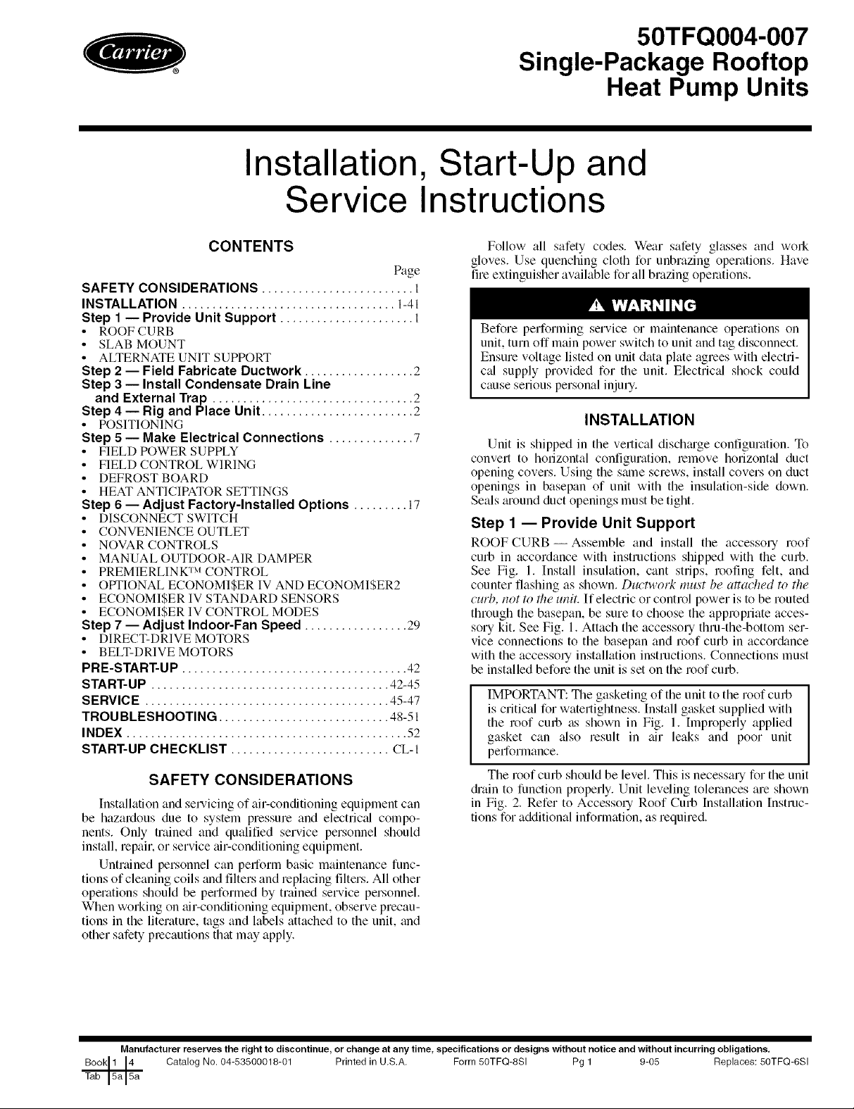
INSTALLATION
Unit is shipped in the vertical dischtuge configuration. To
convert to horizontal configuration, remove horizont_d duct
opening covers. Using the salne screws, install covers on duct
openings in basepan of unit with the insulation-side down.
Seals tuound duct openings must be tight.
Step 1 -- Provide Unit Support
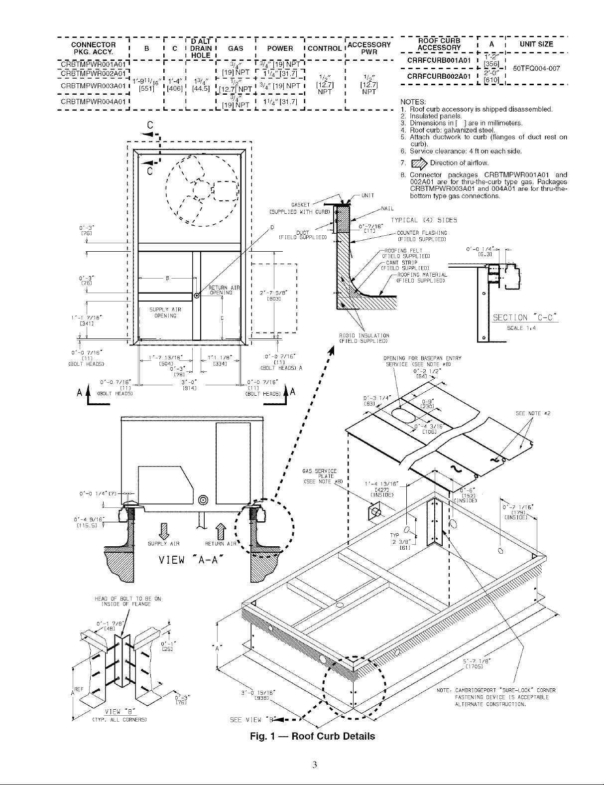
ROOF CURB--Assemble and install the accesso U roof
curb in accordance with instructions shipped with the curb.
See Fig. 1. Install insulation, cant strips, roofing felt, and
counter flashing as shown. Ductwork must be attached to the
curb, not to the unit. If electric or control power is to be routed
through the basepan, be sure to choose the appropriate acces-
sory kit. See Fig. 1. Attach the accessory thru-the-bottom ser-
vice connections to the basepan and roof curb in accor&mce
with the accessoly installation instructions. Connections must
be installed before the unit is set on the roof curb.
IMPORTANT: The gasketing of the unit to the roof curb
is critical for watertightness. Install gasket supplied with
the roof curb as shown in Fig. 1. Improperly applied
gasket can also result in air leaks and poor unit
performance.
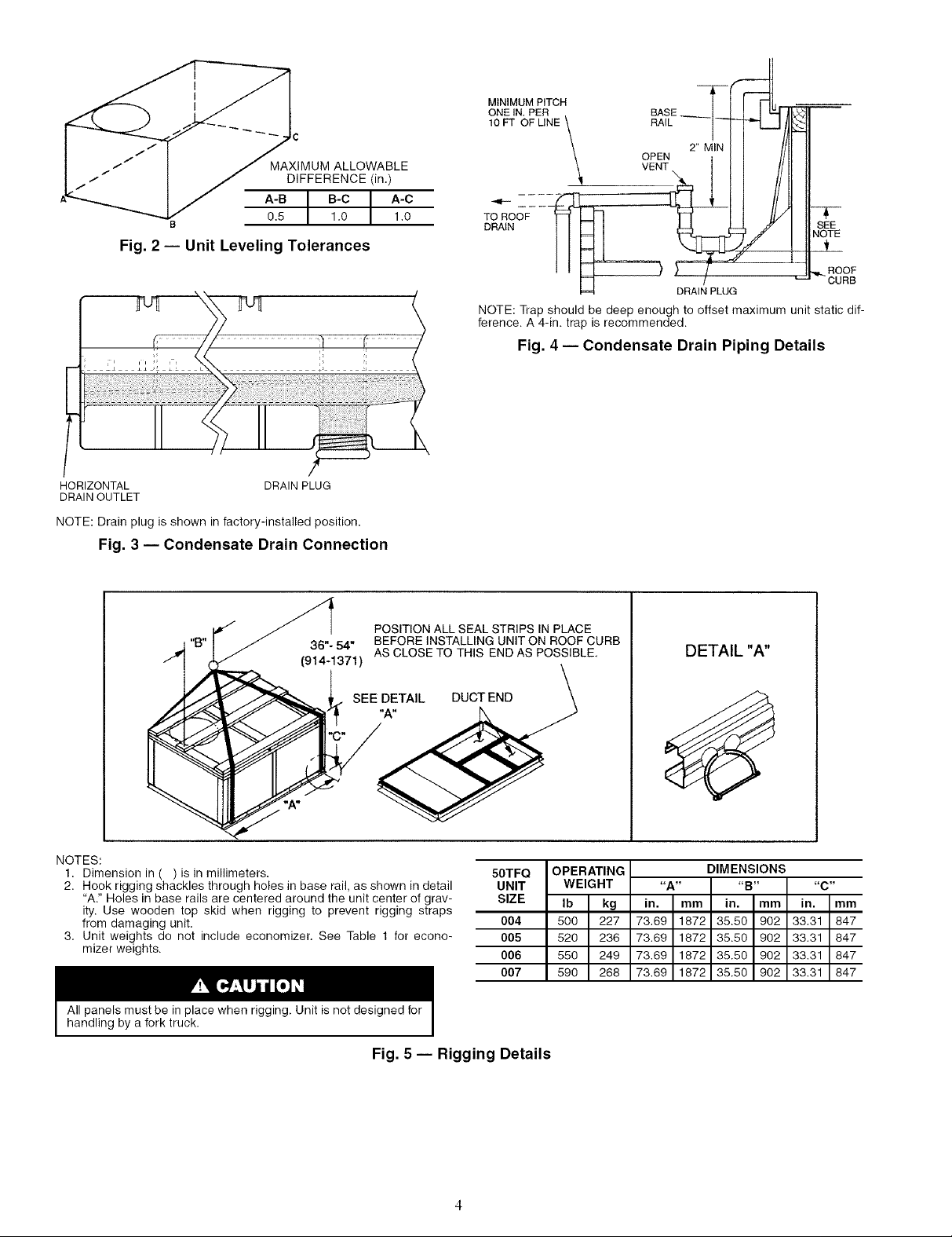
The roof curb should be level. This is necessaU for the unit
drain to function properly. Unit leveling tolerances am shown
in Fig. 2. Refer to Accesso U Roof Curb Installation Instruc-
tions for additional information, as required.
Manufacturer reserves the right to discontinue, or change at any time, specifications or designs without notice and without incurring obligations.
Catalog No. 04-53500018-01 Printed in U,S.A, Form 50TFQ-SSI Pg 1 9-05 Replaces: 50TFQ-dSI
Page 2
SLAB MOUNT (Horizontal Units Only) -- Provide a level
conclete slab that extends a minimum of 6 in. beyond the unit
cabinet. Instffll a gravel apron in flont of the condenser coil air
inlet to prevent grass and foliage from obstructing airflow.
NOTE: Horizontal units may be installed on a roof curb if
required.
ALTERNATE UNIT SUPPORT --When the curb or
a&_pter cannot be used, support unit with sleepers using unit
curb or adapter support area. If sleepel.s cfmnot be used, sup-
poll the long sides of the unit with a minimum of 3 equally
spaced 4-in. x 4-in. pads on each side.
Step 2 -- Field Fabricate Ductwork -- Secure all
ducts to the roof curb and building structure on vertical dis-
charge units. Do not conne_ duct_'ork to the unit. For horizon-
tal applications, field-supplied flanges should be attached to
horizontal discharge openings and all ductwork should be at-
tached to the flanges. Insulate and weatherproof fdl external
ductwork, joints, and roof openings with counterflashing and
mastic in accordance with applicable codes.
Ducts passing through an unconditioned space must be
insulated and covered with a vapor bfuriel:
If a plenum return is used on a vertical unit, the return
should be ducted through the roof deck to comply with applica-
ble fire codes.
A minimum clearance is not requiled around ductwork.
Cabinet return-air static pressure (a negative condition) should
not exceed 0.35 in. wg with economizer or 0.45 in. wg without
economizer.
Step 3 -- Install Condensate Drain Line and
External Trap -- Condensate drain connections are locat-
ed on the bottom and side of the unit. Unit discharge connec-
tions do not determine the use of drain connections; either
drain connection can be used with vertical or horizontal dis-
charge units.
When using the standfud side drain connection, make sure
the plug in the alternate bottom connection is tight before
installing the unit.
To use the bottom &'ain connection for a roof curb installa-
tion, relocate the factory-installed plug from the bottom con-
nection to the side connection. The center &ain plug looks like
a star connection, but can be removed using a l/2-in, socket
drive extension. See Fig. 3. The piping for the condensate &'ain
and external trap can be completed after the unit is in place.
All units must have an externfd trap for condensate &'ain-
age. Instfdl a trap fit least 4 in. deep and protect against freeze-
up. If the drain line is installed downstream from the external
trap, pitch the line away from the 50TFQ unit at 1/4 in. per ft of
run. Do not use a pipe size smaller than the unit connection.
See Fig. 4.
Step 4 -- Rig and Place Unit -- Inspect the unit for
transportation dalnage, and tile any clailn with the transpomt-
tion agency. Keep the unit upright and do not drop it. Spreader
baLs are not required if top crating is left on the unit, and rollers
may be used to move the unit across a roof. Level by using the
unit frame as a reference. See Table 1 and Fig. 5 for additional
information. Operating weight is shown in Table 1 and Fig. 5.
Lifting holes are provided in base rails as shown in Fig. 5
and 6. Refer to rigging instructions on the unit.
All panels must be in place when rigging. Unit is not
designed for handling by a fork truck. Dmnage to unit may
result.
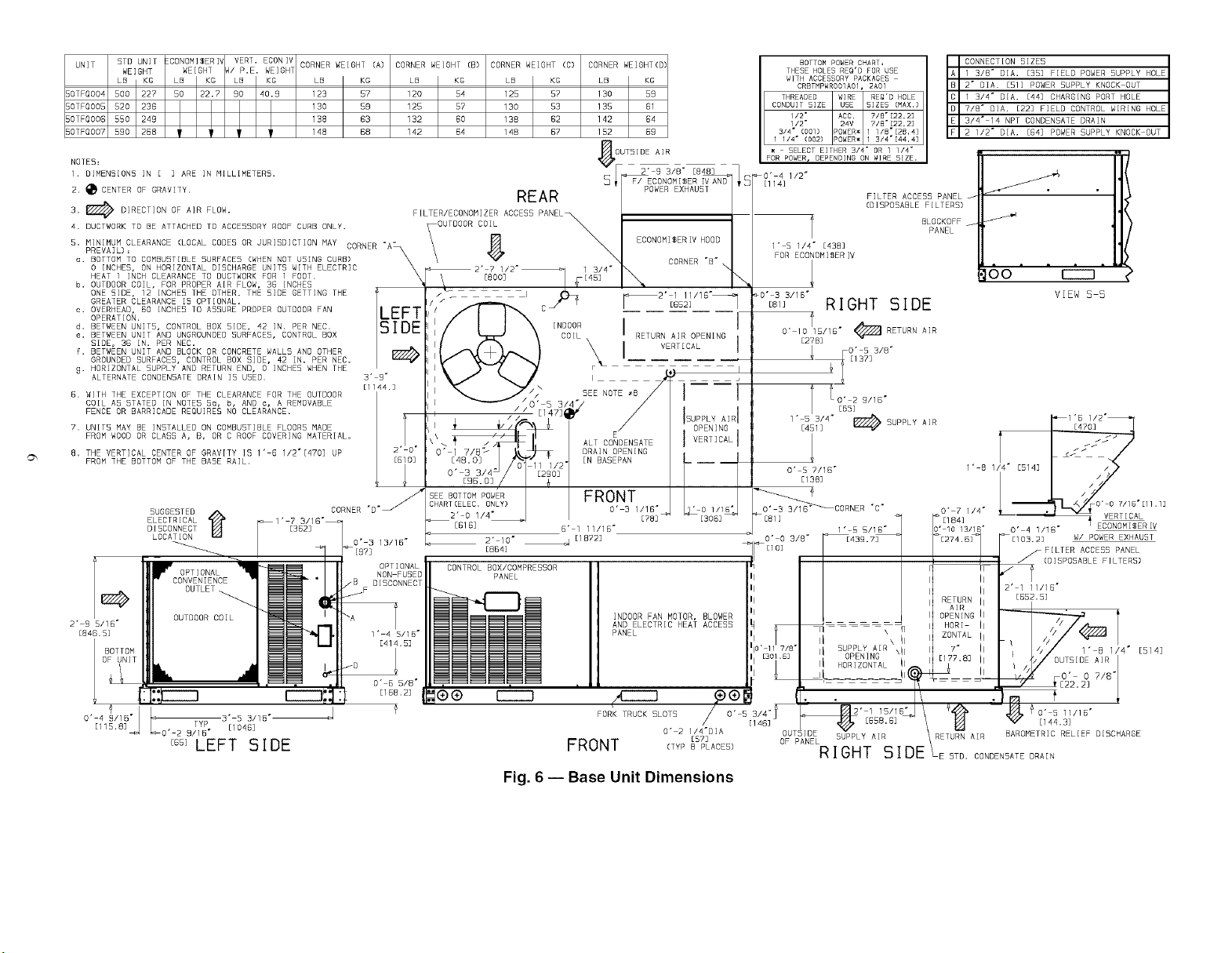
POSITIONING -- Maintain clefu'ance fu'ound and above the
unit to provide proper airflow find service access. See Fig. 6.
A properly positioned unit will have the following clearanc-
es: l/4-in, clearance between the roof curb and base rails on
each side and front of the unit; l/4-in, clemance between the
roof curb and rear of unit. (See Fig. 1, section C-C.)
Do not install the unit indool_. Do not locate the unit air in-
lets near exhaust vents or other soumes of contaminated all:
Although the unit is weatherproof, gufud against water from
higher level runoff and overhangs.
After the unit is in position, remove the polyethylene ship-
ping wrapper and top crating.
Page 3
CONNECTOR I B I C I DRAIN I GAS I POWER I CONTROL
PKG. ACCY, i i i HOLE i i i
i i I DALT i I i
CRBTMPWROO1A01 I I I I 3/,d, I 3/4, [19] NPT I
"C-_T_l_W-R_O_'A511 I I I [19]NPT r _1_4,,_3T.)"] 1
......... -I , 11 ,_1 , ,_ I 3 _ I- - _ - - -I- ...... I 1/S
CRBTMPWROO3A01 i [551] 11406]1 [445] i[1271NPTi 3/4" [19] NPT i [12.7]
......... •4 " " i" "l " " " i-_-'T, _-4. ...... i NPT
CRBTMPWROO4A011 I I I l@_/41PT I 11/4"[31.7] I
1-9 /16 1-4 1 /4 /2"
_J .... L _ _ I- _ _ _L ._J--'_ L ..... --I .....
C
|
C
/ \ / \\
I I r_ ii
k / / /
URNAI OPEN I NG
SUPPLY AIR
OPENING C
ETG]
3" O"
[914]
5UPPLY AIR RETURN AIR %
I
I
I
I
I
I
I
I GABKET
I (SUPPLIED WITH CURB)
I
I
I
I I
I t
I t
I 2" 7 5/8" t
I [BI I
I I
I I
I I
I I
I
-- J
' F
O" 0 7/15"
Ell]
(BOLT HEADB) A
#
I PLATE
• (SEE NOTE
E
I
%
#
DUCTI [FIELD SUPPLIED)
I
l
I
t
|
I
I
l
I
I
I
#
I
GA5 5ERVICE
3" I
7B] I
3" I
_5] I
1" ] 7/16" I
41]
O" 0 7/16"
[11]
CBOLT HEADS)
O' 0 ?/16"
A HEAD5)
L_T [ll]_
O' 0 I/4"[7]
O" 4 9/16"
Ell 5.53
I
I
I
I
I
I
I
I
I
I
I
I
I
I
I
I
I
VIEW "AJA"
HEAD OF BOLT TO BE ON
INBIDE OF FLANGE
RIGID IN5ULATION
(FIELD 5UPPLIED)
,11
I
ACCESSORY
PWR
1/2"
[12.7]
NPT
I- ......
O" 7/16"
O' 3 1/4"
[B3]
1" 4 13/16"
ROOF CURB r - - -i .........
ACCESSORY i A I UNIT SIZE
CRRFCURBOOIA01_ T'-_"-',.........
CRRFCURB002A01 i 2-0 i
NOTES:
1. Roof curb accessory is shipped disassembled.
2. Insulated panels.
3. Dimensions in [ ] are in millimeters.
4. Roof curb: galvanized steel.
5. Attach ductwork to curb (flanges of duct rest on
curb).
6. Service clearance: 4 ft on each side.
7. I_ Direction of airflow.
8. Connector packages CRBTMPWROO1A01 and
002A01 are for thru-the-curb type gas. Packages
CRBTMPWROO3A01 and 004A01 are for thru-the-
bottom type gas connections.
TYPICAL (4) 5IDES
FLASHING
(FIELD SUPPLIED)
FELT
(FIELD SUPPLIED)
STRIP
SUPPLIED)
MATERIAL
(FIELD SUPPLIED)
OPENING FOR BA5EPAN ENTRY
SERVICE (BEE NOTE #B)
O" 2 1/2"
0 9"
[427]
(INSIDE)
TYP
2 3/8"
[613
I
I
I
I
I
[152]
[INSIDE)
OTFOO04-007
.........
o,old$S.:_
o
SECTION "C C"
SCALE l :4
o
5EE NOTE _2
B"
1/1B"
VIEW "B"
(TYP. ALL CORNERS)
o" 1"
E25]
>/_o, 3"
[?G]
3' 0 15/16"
EBBB]
SEE VIEW "E_-
Fig. 1 -- Roof Curb Details
I/8"
%
El 705]
NOTE= CAMBR[DGEPORT "5URE LOCK" CORNER
FA5TENING DEVICE IB ACCEPTABLE
ALTERNATE CONSTRUCTION.
Page 4
_X:
IMUM ALLOWABLE
I-"/" I J DIFFERENCE (in.)
IJ A-RI B-cI A-c
0.5 I 1.0 I 1.0
Fig. 2 -- Unit Leveling Tolerances
HORIZONTAL DRAIN PLUG
DRAIN OUTLET
NOTE:Drain plug is shown infactory-installed position.
Fig. 3 -- Condensate Drain Connection
MINIMUM PITCH
ONE IN. PER
10 FT OF LINE
TO ROOF
DRAIN
-7-
SEE
NOTE
_L_
,,q_ROOF
DRAIN PLUG
NOTE: Trap should be deep enough to offset maximum unit static dif-
ference. A 4-in. trap is recommended.
CURB
Fig. 4 -- Condensate Drain Piping Details
POSITION ALL SEAL STRIPS IN PLACE
36"- 54"
(914-1371 )
NOTES:
1. Dimension in ( ) is in millimeters.
2. Hook rigging shackles through holes in base rail, as shown in detail
"A." Holes in base rails are centered around the unit center of grav-
ity. Use wooden top skid when rigging to prevent rigging straps
from damaging unit.
3. Unit weights do not include economizer. See Table 1 for econo-
mizer weights.
All panels must be in place when rigging. Unit is not designed for
handling by a fork truck.
BEFORE INSTALLING UNIT ON ROOF CURB
AS CLOSE TO THIS END AS POSSIBLE,
SEE DETAIL DUCT END
Fig. 5 -- Rigging Details
50TFQ
UNIT
SIZE
004
OO5
006
007
\
P
OPERATING
WEIGHT
Ib kg
500 227
520 236
550 249
590 268
DETAIL "A"
DIMENSIONS
"A .... B .... C"
in. mm in. mm in. mm
73.69 1872 35.50 902 33.31 847
73.69 1872 35.50 902 33.31 847
73.69 1872 35.50 902 33.31 847
73.69 1872 35.50 902 33.31 847
Page 5
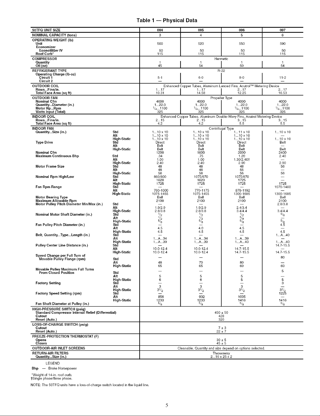
Table 1 -- Physical Data
50TFQ UNIT SIZE
NOMINAL CAPACITY (tons)
OPERATING WEIGHT (Ib)
Unit
Economizer
EconoMi$er IV
Roof Curb*
COMPRESSOR
Quantity
Oil (oz)
REFRIGERANT TYPE
Operating Charge (Ib-oz)
Circuit 1
Circuit 2
OUTDOOR COIL
Rows...Fins/in.
Total Face Area (sq ft)
OUTDOOR FAN
Nominal Cfm
Quantity...Diameter (in.)
Motor Hp...Rpm
Watts Input/Total)
INDOOR COIL
Rows...Fins/in.
Total Face Area (sq ft)
INDOOR FAN
Quantity...Size (in.)
Type Drive
Nominal Cfm
Maximum Continuous Bhp
Motor Frame Size
Nominal Rpm High/Low
Fan Rpm Range
Motor Bearing Type
Maximum Allowable Rpm
Motor Pulley Pitch Diameter Min/Max (in.)
Nominal Motor Shaft Diameter (in.)
Fan Pulley Pitch Diameter (in.)
Belt, Quantity...Type...Length (in.)
Pulley Center Line Distance (in.)
Speed Change per Full Turn of
Movable Pulley Flange (rpm)
Movable Pulley Maximum Full Turns
From Closed Position
Factory Setting Std
Factory Speed Setting (rpm) Std
Fan Shaft Diameter at Pulley (in.)
HIGH-PRESSURE SWITCH (psig)
Standard Compressor Internal Relief (Differential)
Cutout
Reset (Auto.)
LOSS-OF-CHARGE SWITCH (psig)
Cutout
Reset (Auto.)
FREEZE-PROTECTION THERMOSTAT (F)
Opens
Closes
OUTDOOR-AIR INLET SCREENS
RETURN-AIR FILTERS
Quantity...Size (in.)
LEGEND
Bhp -- Brake Horsepower
*Weight of 14-in. roof curb.
1-Singlephase/three phase.
NOTE: The 50TFQ units have a loss-of-charge switch located in the liquid line.
Std
AIt
High-Static
Std
AIt
High-Static
Std
AIt
High-Static
Std
AIt
High-Static
Std
AIt
High-Static
Std
AIt
High-Static
Std
AIt
High-Static
Std
AIt
High-Static
Std
AIt
High-Static
Std
AIt
High-Static
Std
AIt
High-Static
Std
AIt
High-Static
Std
AIt
High-Static
AIt
High-Static
AIt
High-Static
004 005 006 007
3 4 5 6
500 520 550 590
50 50 50 50
115 115 115 115
1 1 1 1
45 I 54 I 50 I 54
5-1 I 6-0 8-0 11-2
Enhanced Copper Tubes, Aluminum Lanced Fins, AcutroF M Metering Device
1._17 I 1_.17 I 2_.17 I 2...1710.31 14.58 12.25 16.53
4000 I 4000 4000 4000
1/4...1100 1/4...1100 1/4...1100 1/4...1100
1 _.22.0 I 1...22.0 1 ...22.0 1...22.0
325 325 325 325
Enhanced Copper Tubes, Aluminum Double-Wavy Fins, Acutrol Metering Device
2...154.2 I 2...154.2 I 3...155.5 I 3...155.5
1...10 x 10 1...10 x 10 1...11 xlO 1...10 x 10
1...10 x 10 1...10 x 10 1...10 x 10 --
1...10 x 10 1...10 x 10 1...10 x 10 1...10 x 10
Direct Direct Direct Belt
Belt Belt Belt --
Belt Belt Belt Belt
1200 1600 2000 2400
.34 .75 1.20 2.40
1.O0 1.00 1.30/2.401-
2.40 2.40 2.90 2.90
48 48 48 56
48 48 56 --
56 56 56 56
860/800 1075/970 1075/970 --
1620 1620 1725 --
1725 1725 1725 1725
-- -- -- 1070-1460
760-1000 770-1175 878-1192
1075-1455 1075-1455 1300-1685 1300-1685
Ball Ball Ball Ball
2100 2100 2100 2100
1_9 1_9 24_4 2.6/3.6_
2.8/3.8 2.8/3.8 3.4/4.4 3.4/4.4
1/2 1/2 1/2 5/8
-- -- -- 4.5
4.5 4.0 4.5 --
4.5 4.5 4.5 4.5
-- -- -- 1...A...40
1 ...A-.34 1-.A...34 1...A...39
1 ...A...39 1...A...39 1...A...40 1...A.-40
10._ 2.4 10._ 2.4 14.7_ 5.5 14.7-15.5__
10.0-12,4 10.0-12.4 14,7-15.5 14,7-15.5
-- -- -- 80
48 70 80
65 65 60 60
-- -- -- 5
5 5 5 --
6 6 5 5
-- -- -- 3
3 3 3 --
31/2 31/2 31/2 31/2
m
Hermetic
R-22
Propeller Type
Centrifugal Type
_8 ;;2 1;;5 1225_
1233 1233 1416 1416
5/8 5/5 5/8 5/8
450 -+ 50
428
32O
7-+3
22-+7
30-+5
45-+5
Cleanable. Quantity and size depend on options selected.
Throwaway
2...16 x 25 x 2
Page 6
UNiT 5TO UNIT [CONOMISERIV VERT. ECONIV CORNER WEIGHT (A) CORNER WEIGHT [B) CORNER WEIGHT (C) CORNER WEIGHT(D
WEIGHT WEIGHT M P.E. WEIGH1
5OTFQO04 500 227 50 22.7 90 4O.S 123 57 120 54 125 57 130 59
5OTFQO05 520 23B 130 59 125 57 130 53 135 B1
5OTFQO06 550 249 138 63 132 GO 138 G2 142 B4
5OTFQO0? 590 268 148 B8 142 G4 148 G7 152 GS
LB KG LB KG LB XG LB XG LB KG LB KG LB XG
NOTES:
I. OIMEN5[ON5 IN E ] ARE IN MILL[METER5.
2. _CENTER OF GRAVITY. REAR
3. @ DIRECTiON OF AiR FLOW.
4. DUCTWORK TO BE ATTACHED TO ACCESSORY ROOF CURB ONLY. ,OUTDOOR COlL
5. MINIMUM CLEARANCE (LOCAL CODES OR JURISDICTION MAY - -
o. BOTTOM TO COMBUSTIBLE SURFACED (WHEN NOT USING CURB)
0 INCHES, ON HORIZONTAL DISCHARGE UNITS WITH ELECTRIC _2" 7
PREVAIL)= CORNER A3
HEAT l INCH CLEARANCE TO DUCTWORK FOR l FOOT. _ [800]
b. OUTDOOR COIL, FOR PROPER AIR FLOW, 36 INCHES
ONE BIDE, 12 INCHED THE OTHER. THE 51DE GETTING THE _ . I
GREATER CLEARANCE IS OPTIONAL.
c. OVERHEAD, 50 INCHED TO ASSURE PROPER OUTDOOR FAN C
OPERATION.
d. BETWEEN UNITS, CONTROL BOX SIDE, 42 IN. PER NEC. SIDE
e. BETWEEN UNIT AND UNGROUNDED SURFACED, CONTROL BOX w=--I
SIDE, 38 IN. PER NEC.
fI BETWEEN UNIT AND BLOCK OR CONCRETE WALLS AND OTHER
GROUNDED SURFACES, CONTROL BOX SIDE, 42 IN. PER NEC.
g. HORIZONTAL SUPPLY AND RETURN END, 0 INCHES WHEN THE i
ALTERNATE CONDENSATE DRAIN ]5 UBED. 3' S"
5. WITH THE EXCEPTION OF THE CLEARANCE FBR THE OUTDOOR
COIL AS STATED IN NOTES Bu, b, AND c_ A REMOVABLE
FENCE OR BARRICADE REQUIRES NO CLEARANCE.
7. UNITS MAY BE INSTALLED ON COMBUSTIBLE FLOORS MADE
FROM WOOD OR CLASS A, B, OR C ROOF COVERING MATERIAL.
8. THE VERTICAL CENTER OF GRAVITY IS 1" G 1/2"[4703 UP
FROM THE BOTTOM OF THE BABE RAIL.
[1144.]
CORNER "D"y
F ILTER/ECONOM[ZER ACCESS
\
LEFT
2 'l O"
[BlO]
INDOOR
COIL
OUTSIDE AIR
2' 9 3/8" E848] ]
F/ ECONOMISER IV AND
F_F/PoWER EXHAUS_
ECONOMISER[V HOOD
I RETURN AIR OPENING I
i
CORNER "B"
VERT BALI
BOTTOM POWER CHART,
THESE MOLE5 REQ'D FOR U5E
WITH ACCESSORY PACKAGES
CRBTMPWROO1AOl, 2A01
THREADED WIRE REQ'D HOLE
CONDUIT13/4"1/4.1/2"1/2"(001)(002)SIZE _
5ELECT EITHER 3/4" OR 1 1/4"
FOR POWERt DEPENDING ON WIRE SIZE.
1/2"
[ll 4]
1" B 1/4" [438]
FOR ECONOM]$ER IV
20" 3 3/15"
FILTER ACCESS
(OlSPO5ABLE FILTERS)
[81] RIGHT BIDE
0"10!5/16" <_ RETURN AIR
[27B]
O' 5 3/8"
_ [137]
CONNECTION SIZES
1 3/8" DIA. [35] FIELD POWERSUPPLY HOLE
2" D]A. [51] POWERSUPPLY KNOCKOUT
1 3/4" DIA. [44] CHARGING PORT HOLE
BLOCKOFF
PANEL
DO r----i
ViEW S 5
2" B 5/16"
[846.5]
41
IgF°; °I T
O' 4 S/1B"
[115.83 TYP 3' S
EGSILEFT SIDE
9/1B" [104G]
Fig. 6 -- Base Unit Dimensions
Page 7
Step 5 -- Make Electrical Connections
Unit cabinet must have an uninterrupted, unbroken electri-
cal ground to minimize the possibility of personal inju U if
an electrical fault should occm: This ground may consist of
electrical wire connected to unit ground lug in control com-
partment, or conduit approved for electrical ground when
installed in accordance with NEC (National Electrical
Code), ANSI/NFPA (American National Standards Insti-
tute/National Fire Protection Association) 70 (latest year),
and local electrical codes. Failure to follow this warning
could result in the installer being liable for personal inju U
of others.
FIELD POWER SUPPLY -- All units except 208/230-v
units are facto U wired for the voltage shown on the nameplate.
If the 208/230-v unit will be connected to a 208-v power sup-
ply, the transformer must be rewired by disconnecting the
black wire from the 230-v temrinal on the transformer and
connecting it to the 200-v terminal from the transformel:
Refer to the unit label diagram for additional information.
Pigtails are provided for field wire connections. Use factory-
supplied splices or a UL (Underwriters' Laboratories)
approved copper/aluminum connectoc
When installing units, provide a disconnect per the
NEC. All field wiring must comply with the NEC and local
requirements.
Inst_dl field wiring as follows:
1. Install conduit through the side panel openings. For units
without electric heat, inst_dl conduit between the discon-
nect and control box.
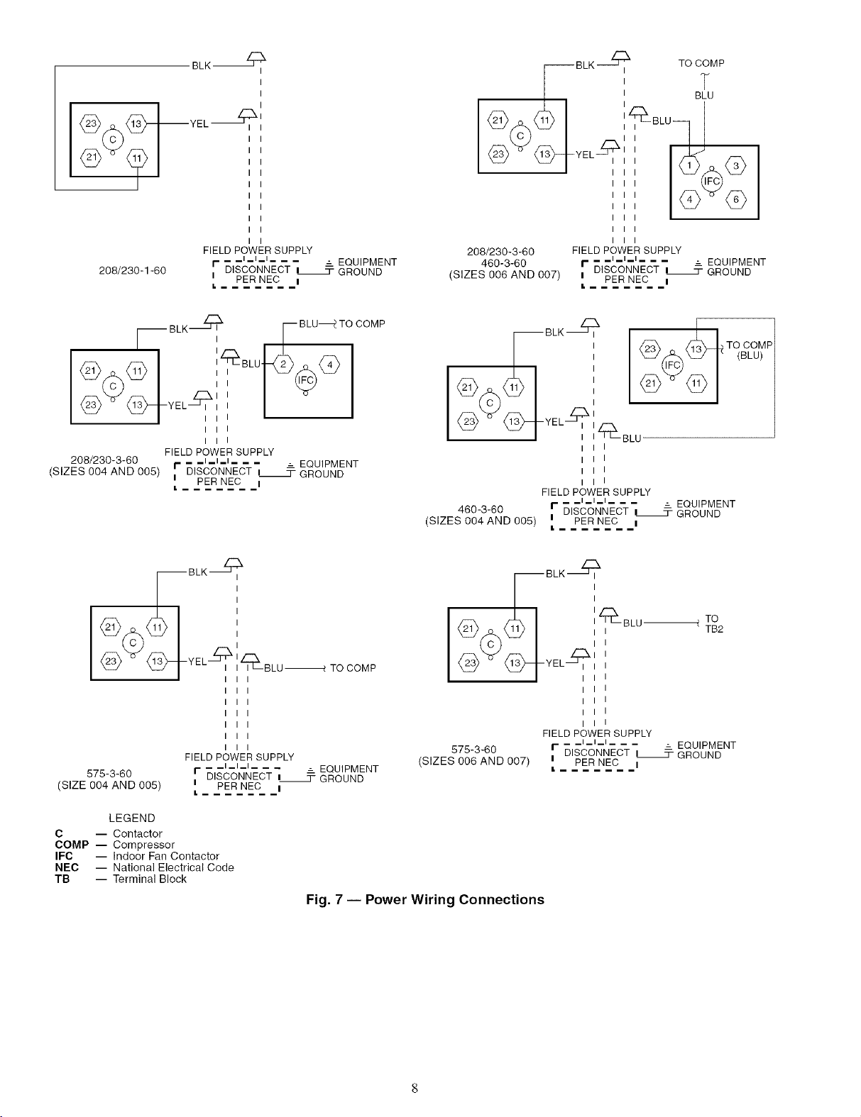
2. [nst_dl power lines to terminal connections as shown in
Fig. 7.
3. For units with electric heat, refer to Table 2 and Accessory
Electric Heat Inst_dlation Instructions.
During operation, voltage to compressor terminals must be
within the range indicated on the unit nmneplate (also see
Tables 3A and 3B). On 3-phase units, voltages between phases
must be balanced within 2% and the cunent within 10%. Use
the formula shown in Tables 3A and 3B and Note 2, on page 12
to determine the percentage of voltage imbalance. Operation
on improper line voltage or excessive phase imbalance consti-
tutes abuse and may cause dmnage to electrical components.
Such operation invali&_tes any applicable Carrier w_uranty.
NOTE: If the unit is mounted on a roof curb and the electrical
power will be run up "thin-the-bottom," be sure to choose the
proper accessory kit shown in Fig. 1. This kit, available from
your local distributor, ensures a leliable watertight connection.
Refer to the thru-the-bottom accessory installation instructions
for information on wiring the unit.
Page 8
BLK _
<_ _J_YEL_"
I
I
I
-BLK ? TO ii_P
FIELD POWER SUPPLY
_ _l_l_l_ _ _ _ EQUIPMENT
208/230-1-60 i PER NEC i
FIELD POWER SUPPLY
208/230-3-60 I- - _l_l_l_ _ _ _ EQUIPMENT
(SIZES 004 AND 005) i DISCONNECT i_ GROUND
r DISCONNECT i 3-GROUND
L
BLK_ I_ BLU_ TO COMP
I
I
PER NEC i
L
BLK_
<_A%<_i
208/230-3-60 FIELD POWER SUPPLY
460-3-60 I- 51 3- GROUND
(SIZES 006 AND 007) i PER NEC i
_c_'_C-T, _EQD_PMENT
L
<_ Q_YEL_:_BLU
I I
I I
I I
FIELD POWER SUPPLY
460-3-60 I-- _l_l_l___ = EQUIPMENT
(SIZES 004 AND 005) I PER NEC I
_-i BLK?
I I
DISCONNECT I_ GROUND
L --
TO
TB2
TO COMP
(BLU)
FIELD POWER SUPPLY
575-3-60
SIZE 004 AND 005) i PER NEC I
_1 _1_1_ _ _
r ID--ISCONNECT _= GROuNDEQUIPMENT
I. _
LEGEND
C -- Contactor
COMP -- Compressor
IFC -- Indoor Fan Contactor
NEC -- National Electrical Code
TB -- Terminal Block
COMP
TO
<_>Y<_YEL_'
575-3-60 r DISCONNECT i 3- GROUND
(SIZES 006 AND 007) i PER NEC i
Fig. 7 -- Power Wiring Connections
FIELD POWER SUPPLY
_ _l_l_l_ _ _ _ EQUIPMENT
L
Page 9
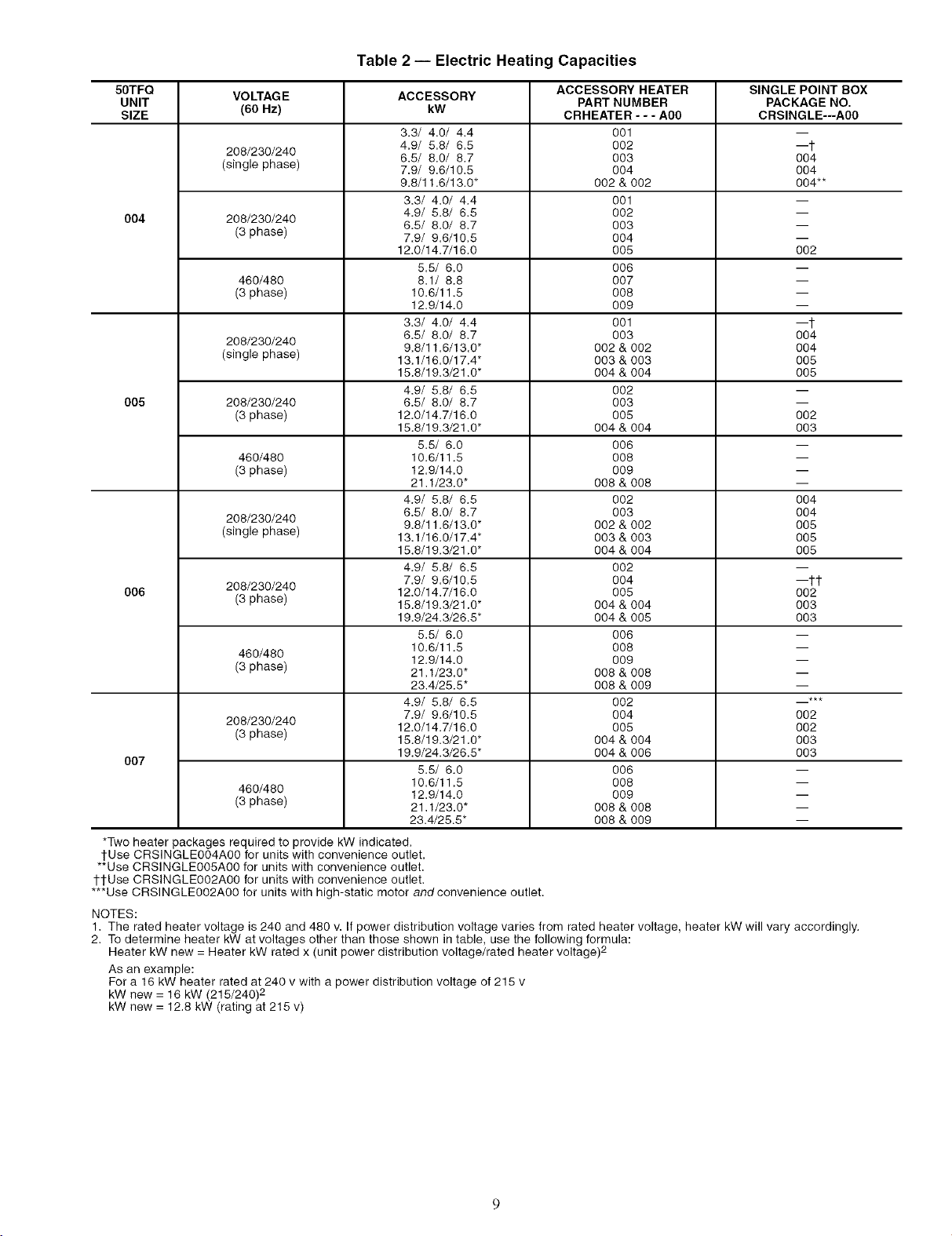
Table2-- Electric Heating Capacities
50TFQ VOLTAGE ACCESSORY ACCESSORY HEATER SINGLE POINT BOX
UNIT PART NUMBER PACKAGE NO.
SIZE (60 Hz) kW CRHEATER - - - A00 CRSINGLE---A00
3.3/ 4.0/ 4.4 001 --
208/230/240 4.9/ 5.8/ 6.5 002 --t
(single phase) 7.9/ 9.6/10.5 004 004
004 208/230/240 6.5/ 8.0/ 8,7 003 --
005 208/230/240 6.5/ 8.0/ 8,7 003 --
006 208/230/240 12.0/14.7/16.0 005 002
007 19.9/24.3/26.5" 004 & 006 003
*Two heater packages required to provide kW indicated.
1-Use CRSINGLE004A00 for units with convenience outlet.
**Use CRSINGLE005A00 for units with convenience outlet.
tl-Use CRSINGLE002A00 for units with convenience outlet.
***Use CRSINGLE002A00 for units with high-static motor and convenience outlet.
NOTES:
1. The rated heater voltage is 240 and 480 v. If power distribution voltage varies from rated heater voltage, heater kW will vary accordingly.
2. To determine heater kW at voltages other than those shown in table, use the following formula:
Heater kW new = Heater kW rated x (unit power distribution voltage/rated heater voltage) 2
As an example:
For a 16 kW heater rated at 240 v with a power distribution voltage of 216 v
kW new = 16 kW (215/240) 2
kW new = 12.8 kW (rating at 215 v)
(3 phase) 7.9/ 9.6/10.5 004 --
460/480 8.1/ 8.8 007 --
(3 phase) 10.6/11,5 008 --
208/230/240 9.8/11.6/13.0" 002 & 002 004
(single phase) 13.1/16.0/17.4" 003 & 003 005
(3 phase) 12.0/14.7/16.0 005 002
460/480 10.6/11.5 008 --
(3 phase) 12.9/14.0 009 --
208/230/240 9.8/11.6/13.0" 002 & 002 005
(single phase) 13.1/16.0/17.4" 003 & 003 005
(3 phase) 18.8/19.3/21.0" 004 & 004 003
460/480 12.9/14.0 009 --
(3 phase) 21.1/23.0" 008 & 008 --
208/230/240 12.0/14.7/16.0 005 002
(3 phase) 18.8/19.3/21.0" 004 & 004 003
460/480 12.9/14.0 009 --
(3 phase) 21.1/23.0" 008 & 008 --
6.5/ 8.0/ 8.7 003 004
9.8/11.6/13.0* 002 & 002 004**
3.3/ 4.0/ 4.4 001 --
4.9/ 5.8/ 6.5 002 --
12.0/14.7/16.0 006 002
5.5/ 6,0 006 --
12.9/14.0 009 --
3.3/ 4.0/ 4.4 001 --t
6.5/ 8.0/ 8.7 003 004
16.8/19.3/21.0" 004 & 004 005
4.9/ 5.8/ 6.5 002 --
15.8/19.3/21.0" 004 & 004 003
5.5/ 6.0 006 --
21.1/23.0" 008 & 008 --
4.9/ 5.8/ 6.5 002 004
6.5/ 8.0/ 8.7 003 004
18.8/19.3/21.0" 004 & 004 005
4.9/ 5.8/ 6.5 002 --
7.9/ 9.6/10.5 004 --1-1-
19.9/24.3/26.5" 004 & 005 003
5.5/ 6.0 006 --
10.6/11.5 008 --
23.4/25.5" 008 & 009 --
4.9/ 5.8/ 6.5 002 --***
7.9/ 9.6/10.5 004 002
5.5/ 6.0 006 --
10.6/11,5 008 --
23.4/25.5" 008 & 009 --
Page 10
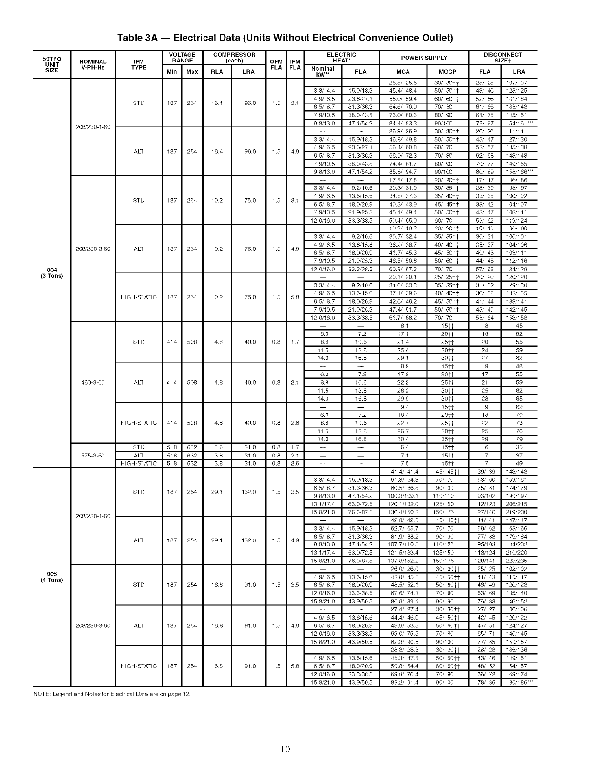
Table 3A -- Electrical Data (Units Without Electrical Convenience Outlet)
50TFQ
UNIT
SIZE
004
(3Tons)
005
(4Tons)
NOTE: Legend and Notes for Electrical Data are on page 12.
NOMINAL
V-PH-Hz
208/230-1-60
208/230-3-60
460-3-60
575-3-60
208/230-1-60
208/230-3-60
IFM RANGE (each) OFM IFM
TYPE FLA FLA Nominal
STD 187 254 16.4 96.0 1.5 3.1
ALT 187 254 16.4 96.0 1.5 4.9
STD 187 254 10.2 75.0 1.5 3.1
ALT 187 254 10.2 75.0 1.5 4.9
HIGH-STATIC 187 254 10.2 75.0 1.5 5.8
STD 414 508 4.8 40.0 0.8 1.7 8.8 10.6 21.4
ALT 414 508 4.8 40.0 0.8 2.1 8.8 10.6 22.2
HIGH-STATIC 414 508 4.8 40.0 0.8 2.6 8.8 10.6 22.7
STD 518 632 3.8 31.0 0.8 1.7 -- -- 6.4
ALT 518 632 3.8 31.0 0.8 2.1 -- -- 7.1
HIGH-STATIC 518 632 3.8 31.0 0.8 2.6 -- -- 7.5
STD 187 254 29.1 132.0 1.5 3.5
ALT 187 254 29.1 132.0 1.5 4.9
STD 187 254 16.8 91.0 1.5 3.5 6.5/ 8.7 18.0/20.9 48.5/ 52.1
ALT 187 254 16.8 91.0 1.5 4.9 6.5/ 8.7 18.0/20.9 49.9/ 53.5
HIGH-STATIC 187 254 16.8 91.0 1.5 5.8 6.5/ 8.7 18.0/20.9 50.8/ 54.4
VOLTAGE COMPRESSOR
MIn Max RLA LRA kW** FLA MCA
ELECTRIC
HEAT* POWER SUPPLY
-- -- 25.5/ 25.5
3.3/ 4.4 15.9/18.3 45.4/ 48.4
4.9/ 6.5 23.6/27.1 55.0/ 59.4
6.5/ 8.7 31.3/36.3 64.6/ 70.9
7.9/10.5 38.0/43.8 73.0/ 80.3
9.8/13.0 47.1/54.2 84.4/ 93.3
-- -- 26.9/ 26.9
3.3/ 4.4 15.9/18.3 46.8/ 49.8
4.9/ 6.5 23.6/27.1 56.4/ 60.8
6.5/ 8.7 31.3/36.3 66.0/ 72.3
7.9/10.5 38.0/43.8 74.4/ 81.7
9.8/13.0 47.1/54.2 85.8/ 94.7
-- -- 17.8/ 17.8
3.3/ 4.4 9.2/10.6 29.3/ 31.0
4.9/ 6.5 13.6/15.6 34.8/ 37.3
6.5/ 8.7 18.0/20.9 40.3/ 43.9
7.9/10.5 21.9/25.3 45.1/ 49.4
12.0/16.0 33.3/38.5 59.4/ 65.9
-- -- 19.2/ 19.2
3.3/ 4.4 9.2/10.6 30.7/ 32.4
4.9/ 6.5 13.6/15.6 36.2/ 38.7
6.5/ 8.7 18.0/20.9 41.7/ 45.3
7.9/10.5 21.9/25.3 46.5/ 50.8
12.0/16.0 33.3/38.5 60.8/ 67.3
-- -- 20.1/ 20.1
3.3/ 4.4 9.2/10.6 31.6/ 33.3
4.9/ 6.5 13.6/15.6 37.1/ 39.6
6.5/ 8.7 18.0/20.9 42.6/ 46.2
7.9/10.5 21.9/25.3 47.4/ 51.7
12.0/16.0 33.3/38.5 61.7/ 68.2
-- -- 8.1
6.0 7.2 17.1
11.5 13.8 25.4
14.0 16.8 29.1
-- -- 8.9
6.0 7.2 17.9
11.5 13.8 26.2
14.0 16.8 29.9
-- -- 9.4
6.0 7.2 18.4
11.5 13.8 26.7
14.0 16.8 30.4
-- -- 41.4/ 41.4
3.3/ 4.4 15.9/18.3 61.3/ 64.3
6.5/ 8.7 31.3/36.3 80.5/ 86.8
9.8/13.0 47.1/54.2 100.3/109.1
13.1/17.4 63.0/72.5 120.1/132.0
15.8/21.0 76.0/87.5 136.4/150.8
-- -- 42.8/ 42.8
3.3/ 4.4 15.9/18.3 62.7/ 65.7
6.5/ 8.7 31.3/36.3 81.9/ 88.2
9.8/13.0 47.1/54.2 107.7/110.5
13.1/17.4 63.0/72.5 121.5/133.4
15.8/21.0 76.0/87.5 137.8/152.2
-- -- 26.0/ 26.0
4.9/ 6.5 13.6/15.6 43.0/ 45.5
12.0/16.0 33.3/38.5 67.6/ 74.1
15.8/21.0 43.9/50.5 80.9/ 89.1
-- -- 27.4/ 27.4
4.9/ 6.5 13.6/15.6 44.4/ 46.9
12.0/16.0 33.3/38.5 69.0/ 75.5
15.8/21.0 43.9/50.5 82.3/ 90.5
-- -- 28.3/ 28.3
4.9/ 6.5 13.6/15.6 45.3/ 47.8
12.0/16.0 33.3/38.5 69.9/ 76.4
15.8/21.0 43.9/50.5 83.2/ 91.4
DISCONNECT
SIZEt
MOCP FLA LRA
30/ 3Oft 25/ 25 107/107
50/ 50tt 43/ 46 123/125
60/ 60tt 52/ 56 131/184
70/ 80 61/ 66 138/143
80/ 90 68/ 75 145/151
90/100 79/ 87 154/161"**
30/ 30it 26/ 26 111/111
50/ 5oft 45/ 47 127/130
60/ 70 53/ 57 135/138
70/ 80 62/ 68 143/148
80/ 90 70/ 77 149/155
90/100 80/ 89 158/166"**
20/ 2Oft 17/ 17 86/ 86
30/ 35tt 28/ 30 95/ 97
35/ 40it 33/ 35 100/102
45/ 45it 38/ 42 104/107
50/ 5oft 43/ 47 108/111
60/ 70 56/ 62 119/124
20/ 20it 19/ 19 90/ 90
35/ 35it 30/ 31 100/101
40/ 4Oft 35/ 37 104/106
45/ 5oft 40/ 43 108/111
50/ 6Oft 44/ 48 112/116
70/ 70 57/ 63 124/129
25/ 25tt 20/ 20 120/120
35/ 35it 31/ 32 129/130
40/ 4Oft 36/ 38 133/135
45/ 5oft 41/ 44 138/141
50/ 6Oft 45/ 49 142/145
70/ 70 58/ 64 153/158
15tt 8 45
20it 16 52
25tt 20 55
30tt 24 59
30tt 27 62
15tt 9 48
20it 17 55
25tt 21 59
30tt 25 62
30it 28 65
15it 9 62
20it 18 70
25tt 22 73
30tt 25 76
35tt 29 79
15tt 6 35
15tt 7 37
15tt 7 49
45/ 45tt 39/ 39 143/143
70/ 70 58/ 60 159/161
90/ 90 75/ 81 174/179
110/110 93/102 190/197
125/150 112/123 206/215
150/175 127/140 219/230
45/ 45tt 41/ 41 147/147
70/ 70 59/ 62 163/166
90/ 90 77/ 83 179/184
110/125 95/103 194/202
125/150 113/124 210/220
150/175 128/141 223/235
30/ 30tt 25/ 25 102/102
45/ 50tt 41/ 43 115/117
50/ 60tt 46/ 49 120/123
70/ 80 63/ 69 135/140
90/ 90 76/ 83 146/152
30/ 30tt 27/ 27 106/106
45/ 50tt 42/ 45 120/122
50/ 60tt 47/ 51 124/127
70/ 80 65/ 71 140/145
90/100 77/ 85 150/157
30/ 30tt 28/ 28 136/136
50/ 50tt 43/ 46 149/151
60/ 60tt 48/ 52 154/157
70/ 80 66/ 72 169/174
90/100 78/ 86 180/186"**
10
Page 11
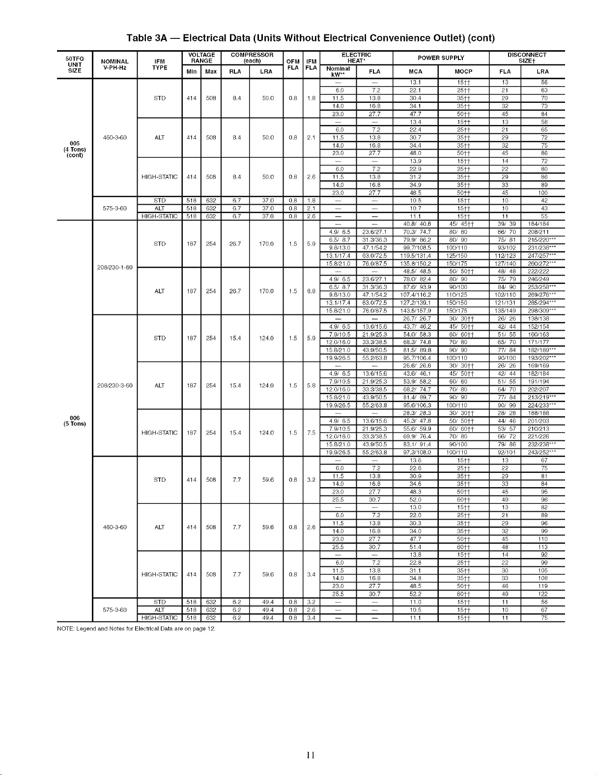
Table 3A -- Electrical Data (Units Without Electrical Convenience Outlet) (cont)
58TFG
UNIT
SIZE
OO5
(4 Tons)
(cont)
006
(5 Tons)
NOTE:Legend and Notes _rElectrical D_a are on page 12.
NOMINAL
V-PH-Hz
460-3-60
575-3-60
208/230-1-60
208/230-3-60
460-3-60
575-3-60 ALT 516 632 6.2
IFM
TYPE
STD
ALT 414 508 6.4
HIGH-STATIC 414 508 6.4
STD 516 632 6.7
ALT 516 632 6.7
HIGH-STATIC 516 632 6.7
STD 187 254 26.7
ALT 187 254 26.7
STD 187 254 15.4
ALT 187 254 15.4
HIGH-STATIC 187 254 15.4
STD 414 508 7.7
ALT 414 508 7.7
HIGH-STATIC 414 508 7.7
STD 516 632 6.2
HIGH-STATIC 516 632 6.2
VOLTAGE COMPRESSOR ELECTRIC
RANGE (each) OFM IFM HEAT* POWER SUPPLY
MIn Max RLA
414 508 6.4
LRA FLA FLA Nominal FLA
50.0 0.8 1.6 11.5 13.8
50.0 0.8 2.1 11.5 13.8
50.0 0.8 2.6 11.5 13.8
37.0 0.8 1.8 -- --
37.0 0.8 2.1 -- --
37.0 0.8 2.6 -- --
170.0 1.5 5.9
170.0 1.5 6.8
124.0 1.5 5.9
124.0 1.5 5.6
124.0 1.5 7.5
59.6 0.8 3.2
59.6 0.8 2.6
59.6 0.8 3.4
49.4 0.8 3.2 -- -- 11.0
49.4 0.8 2.6 -- -- 10.5
49.4 0.8 3.4 -- -- 11.1
kW**
6.0 7.2
14.0 16.8
23.0 27.7
6.0 7.2
14.0 16.8
23.0 27.7
6.0 7.2
14.0 16.8
23.0 27.7
-- -- 40.8/ 40.8
4.9/ 6.5 23.6/27.1 70.3/ 74.7
6.5/ 8.7 31.3/36.3 79.9/ 66.2
9.8/13.0 47.1/54.2 99.7/108.5
13.1/17.4 63.0/72.5 119.5/131.4
15.8/21.0 76.0/87.5 135.8/150.2
-- -- 48.5/ 48.5
4.9/ 6.5 23.6/27.1 78.0/ 62.4
6.5/ 8.7 31.3/36.3 87.6/ 93.9
9.6/13.0 47.1/54.2 107.4/116.2
13.1/17.4 63.0/72.5 127.2/139.1
15.8/21.0 76.0/87.5 143.5/157.9
-- -- 26.7/ 26.7
4.9/ 6.5 13.6/15.6 43.7/ 46.2
7.9/10.5 21.9/25.3 54.0/ 58.3
12.0/16.0 33.3/38.5 66.3/ 74.8
15.8/21.0 43.9/50.5 81.5/ 69.8
19.9/26.5 55.2/63.8 95.7/106.4
-- -- 26.6/ 26.6
4.9/ 6.5 13.6/15.6 43.6/ 46.1
7.9/10.5 21.9/25.3 53.9/ 58.2
12.0/16.6 33.3/38.5 68.2/ 74.7
15.8/21.0 43.9/50.5 81.4/ 69.7
19.9/26.5 55.2/63.8 95.6/106.3
-- -- 28.3/ 28.3
4.9/ 6.5 13.6/15.6 45.3/ 47.8
7.9/10.5 21.9/25.3 55.6/ 59.9
12.0/16.0 33.3/38.5 69.9/ 76.4
15.8/21.0 43.9/50.5 83.1/ 91.4
19.9/26.5 55.2/63.8 97.3/108.0
-- -- 13.6
6.0 7.2 22.6
11.5 13.8 30.9
14.0 16.8 34.6
23.0 27.7 48.3
25.5 30.7 52.0
-- -- 13.0
6.0 7.2 22.0
11.5 13.8 30.3
14.0 16.8 34.0
23.0 27.7 47.7
25.5 30.7 51.4
-- -- 13.8
6.0 7.2 22.8
11.5 13.8 31.1
14.0 16.8 34.8
23.8 27.7 48.5
25.5 30.7 52.2
MCA MOCP
13.1 15tt
22.1 25tt
30.4 35tt
34.1 35tt
47.7 50tt
13.4 15tt
22.4 25it
30.7 36tt
34.4 36tt
48.0 6oft
13.9 15it
22.9 25it
31.2 35it
34.9 35it
48.5 60tt
10.5 15tt
10.7 15it
11.1 15it
45/ 46tt
80/ 80
80/ 90
100/110
125/150
150/175
6o/5ott
8o/ 90
9O/lOO
11o/125
15o/15o
15o/175
3o/ 3oft
45/5ott
6o/ 6oft
7o/ 80
9o/ 90
lOO/11o
30/ 3oft
45/ 5oft
6o/ 60
70/ 80
90/ 90
100/110
30/ 3Oft
6o/ 5ott
6o/ 6oft
70/ 80
90/100
100/110
15tt 13 67
25tt 22 75
35tt 29 81
35tt 33 84
50tt 45 95
6Oft 49 98
15tt 13 82
25tt 21 89
35tt 29 96
35tt 32 99
6oft 45 110
6Oft 48 113
15tt 14 92
25it 22 99
35_t 30 105
35it 33 108
60ft 46 119
6Oft 49 122
15tt 11 56
15tt 10 67
15tt 11 75
DISCONNECT
SIZEt
FLA LRA
13 56
21 63
29 70
32 73
45 84
13 58
21 65
29 72
32 75
45 86
14 72
22 80
29 86
33 89
45 100
10 42
10 43
11 55
39/ 39 184/184
66/ 70 208/211
75/ 81 215/220"**
93/102 231/238"**
112/123 247/257"**
127/140 260/272"**
48/ 48 222/222
75/ 79 246/249
64/ 90 253/258"**
102/110 269/276"**
121/131 285/294"**
135/149 298/309"**
26/ 26 138/138
42/ 44 152/154
51/ 55 160/163
65/ 70 171/177
77/ 84 182/189"**
90/100 193/202"**
26/ 26 169/169
42/ 44 182/184
51/ 55 191/194
64/ 70 202/207
77/ 84 213/219"**
90/ 99 224/233"**
28/ 28 188/188
44/ 46 201/203
53/ 57 210/213
66/ 72 221/226
79/ 86 232/238"**
92/101 243/252"**
11
Page 12
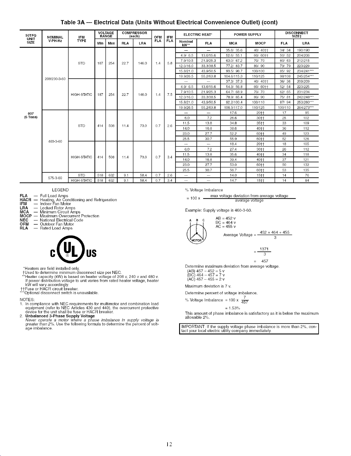
Table 3A -- Electrical Data (Units Without Electrical Convenience Outlet) (cont)
50TFQ
UNIT
SIZE
007
(6 Tons)
NOMINAL
V-PH-Hz
208/230-3-60
460-3-60
575-3-60
IFM RANGE (each) OFM IFM
TYPE MIn Max RLA LRA FLA FLA Nominal FLA
STD 187 254 22.7 146.0 1.4 5.8
HIGH-STATIC 187 254 22.7 146.0 1.4 7.5
STD 414 508 11.4 73.0 0.7 2.6
HIGH-STATIC 414 508 11.4 73.0 0.7 3.4
STD 518 632 9.1 58.4 0.7 2.6 -- --
HIGH-STATIC 518 632 9.1 58.4 0.7 3.4 -- --
LEGEND
FLA -- Full Load Amps
HACR -- Heating, Air Conditioning and Refrigeration
IFM -- Indoor Fan Motor
LRA -- Locked Rotor Amps
MCA -- Minimum Circuit Amps
MOCP -- Maximum Overcurrent Protection
NEC -- National Electrical Code
OFM -- Outdoor Fan Motor
RLA -- Rated Load Amps
VOLTAGE COMPRESSOR ELECTRIC HEAT*
POWER SUPPLY
kW**
4.9/ 6.5 13.6/15.6
7.9/10.5 21.9/25.3
12.0/16.0 33.3/38.5
15.8/21.0 43.9/50.5
19.9/26.5 55.2/63.8
4.9/ 6.5 13.6/15.6
7.9/10.5 21.9/25.3
12.0/16.0 33.3/38.5
15.8/21.0 43.9/50.5
19.9/26.5 55.2/63.8
6.0 7.2
11.5 13.8
14.0 16.8
23.0 27.7
25.5 30.7
6.0 7.2
11.5 13.8
14.0 16.8
23.0 27.7
25.5 30.7
MCA
35.6/ 35.6
52.6/ 55.1
63.0/ 67.2
77.2/ 83.7
90.5/ 98.7
104.6/115.3
37.3/ 37.3
54.3/ 56.8
64.7/ 68.9
78.9/ 85.4
92.2/100.4
106.3/117.0
17.6
26.6
34.8
38.6
52.2
55.9
18.4
27.4
35.6
39.4
53.0
56.7
14.0
14.7
MOCP FLA LRA
40/ 4oft 34/ 34 190/190
60/ 80tt 50/ 52 204/206
70/ 70 80/ 83 212/215
80/ 90 73/ 79 223/229
100/100 85/ 92 234/241"**
110/125 98/108 245/254"**
40/ 40tt 36/ 38 209/209
60/ 6Ott 52/ 54 223/225
70/ 70 62/ 65 231/234
80/ 90 75/ 81 242/248"**
100/110 87/ 94 253/260"**
110/125 100/110 264/273"**
2Oft 17 95
3Oft 25 102
35tt 33 109
40it 36 112
60tt 49 123
60it 52 126
20it 18 105
3Oft 26 112
40it 34 118
40it 37 121
60it 50 132
60it 53 135
15it 14 76
15it 14 84
% Voltage Imbalance
= 100 x max voltage deviation from average voltage
average voltage
Example: Supply voltage is 460-3-60.
A e C AB = 452 v
(_ AC = 455 v
BC = 464 v
Average Voltage =
462 + 464 + 465
3
DISCONNECT
SIZEt
*Heaters are field installed only.
tUsed to determine minimum disconnect size per NEC.
**Heater capacity (kW) is based on heater voltage of 208 v, 240 v and 480 v.
If power distribution voltage to unit varies from rated heater voltage, heater
kW will vary accordingly.
ttFuse or HACR circuit breaker.
***Optional disconnect switch is unavailable.
NOTES:
1. In compliance with NEC requirements for multimotor and combination load
equipment (refer to NEC Articles 430 and 440), the overcurrent protective
device for the unit shall be fuse or HACR breaker.
2. Unbalanced 3-Phase Supply Voltage
Never operate a motor where a phase imbalance in supply voltage is
greater than 2%. Use the following formula to determine the percent of volt-
age imbalance.
1371
3
457
Determine maximum deviation from average voltage.
(AB) 457 -462 = 5 v
(BC) 464 - 457 = 7 v
(AC) 467 - 455 = 2 v
Maximum deviation is 7 v.
Determine percent of voltage imbalance.
7
% Voltage Imbalance = 100 x 457
= 1.53%
This amount of phase imbalance is satisfactory as it is below the maximum
allowable 2%.
IMPORTANT: If the supply voltage phase imbalance is more than 2%, con-
tact your oca e ectr cut ty company turned ate y.
12
Page 13
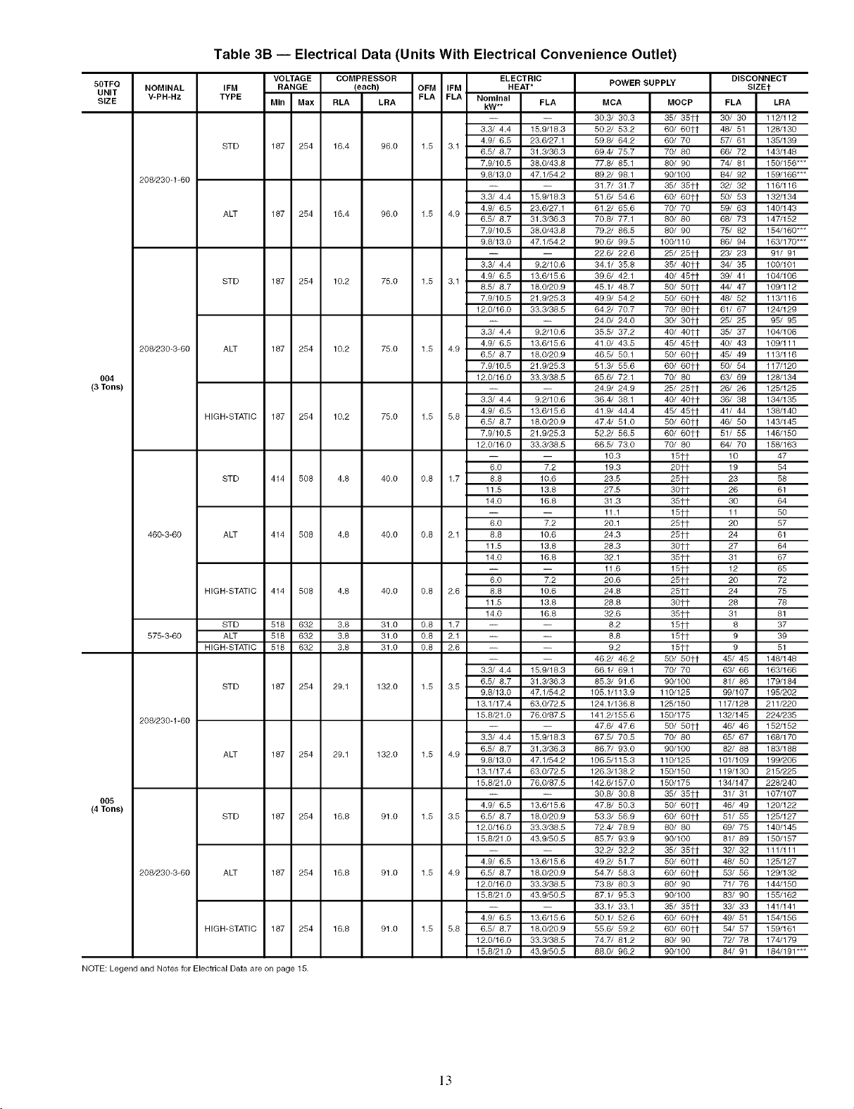
Table 3B -- Electrical Data (Units With Electrical Convenience Outlet)
50TFQ
UNIT
SIZE
004
(3 Tons)
005
(4 Tons)
NOTE: Legend and Notes for Electrical Data are on page 15.
NOMINAL
V-PH-Hz
208/230-1-60
208/230-3-60
460-3-60
575-3-60
208/230-1-60
208/230-3-60
IFM RANGE (each)
TYPE
STD 187 254 16.4
ALT 187 254 16.4
STD 187 254 10.2
ALT 187 254 10.2
HIGH-STATIC 187 254 10.2
STD 414 508 4.8
ALT 414 508 4.8
HIGH-STATIC 414 508 4.8
STD 518 632 3.8
ALT 518 632 3.8
HIGH-STATIC 518 632 3.8
STD 187 254 29.1
ALT 187 254 29.1
STD 187 254 16.8
ALT 187 254 16.8
HIGH-STATIC 187 254 16.8
VOLTAGE COMPRESSOR
MIn Max RLA LRA
OFM IFM HEAT*
FLA FLA Nominal
96.0 1.5 3.1
96.0 1.5 4.9
75.0 1.5 3.1
75.0 1.5 4.9
75.0 1.5 5.8
40.0 0.8 1.7 8.8 10.6 23.5
40.0 0.8 2.1 8.8 10.6 24.3
40.0 0.8 2.6 8.8 10.6 24.8
31.0 0.8 1.7 -- -- 8.2
31.0 0.8 2.1 -- -- 8.8
31.0 0.8 2.6 -- -- 9.2
132.0 1.5 3.5
132.0 1.5 4.9
91.0 1.5 3.5 6.5/ 8.7 18.0/20.9 53.3/ 56.9
91.0 1.5 4.9 6.5/ 8.7 18.0/20.9 54.7/ 58.3
91.0 1.5 5.8 6.5/ 8.7 18.0/20.9 55.6/ 59.2
ELECTRIC
kW**
-- -- 30.3/ 30.3
3.3/ 4.4 15.9/18.3 50.2/ 53.2
4.9/ 6.5 23.6/27.1 59.8/ 64.2
6.5/ 8.7 31.3/36.3 69.4/ 75.7
7.9/10.5 38.0/43.8 77.8/ 85.1
9.8/13.0 47.1/54.2 89.2/ 98.1
-- -- 31.7/ 31.7
3.3/ 4.4 15.9/18.3 51.6/ 54.6
4.9/ 6.5 23.6/27.1 61.2/ 65.6
6.5/ 8.7 31.3/36.3 70.8/ 77.1
7.9/10.5 38.0/43.8 79.2/ 86.5
9.8/13.0 47.1/54.2 90.6/ 99.5
-- -- 22.6/ 22.6
3.3/ 4.4 9.2/10.6 34.1/ 35.8
4.9/ 6.5 13.6/15.6 39.6/ 42.1
8.5/ 8.7 18.0/20.9 45.1/ 48.7
7.9/10.5 21.9/25.3 49.9/ 54.2
12.0/16.0 33.3/38.5 64.2/ 70.7
-- -- 24.0/ 24.0
3.3/ 4.4 9.2/10.6 35.5/ 37.2
4.9/ 6.5 13.6/15.6 41.0/ 43.5
6.5/ 8.7 18.0/20.9 46.5/ 50.1
7.9/10.5 21.9/25.3 51.3/ 55.6
12.0/16.0 33.3/38.5 65.6/ 72.1
-- -- 24.9/ 24.9
3.3/ 4.4 9.2/10.6 36.4/ 38.1
4.9/ 6.5 13.6/15.6 41.9/ 44.4
6.5/ 8.7 18.0/20.9 47.4/ 51.0
7.9/10.5 21.9/25.3 52.2/ 56.5
12.0/16.0 33.3/38.5 66.5/ 73.0
-- -- 10.3
6.0 7.2 19.3
11.5 13.8 27.5
14.0 16.8 31.3
-- -- 11.1
6.0 7.2 20.1
11.5 13.8 28.3
14.0 16.8 32.1
-- -- 11.6
6.0 7.2 20.6
11.5 13.8 28.8
14.0 16.8 32.6
-- -- 46.2/ 46.2
3.3/ 4.4 15.9/18.3 66.1/ 69.1
6.5/ 8.7 31.3/36.3 85.3/ 91.6
9.8/13.0 47.1/54.2 105.1/113.9
13.1/17.4 63.0/72.5 124.1/136.8
15.8/21.0 76.0/87.5 141.2/155.6
-- -- 47.6/ 47.6
3.3/ 4.4 15.9/18.3 67.5/ 70.5
6.5/ 8.7 31.3/36.3 86.7/ 93.0
9.8/13.0 47.1/54.2 106.5/115.3
13.1/17.4 63.0/72.5 126.3/138.2
15.8/21.0 76.0/87.5 142.6/157.0
-- -- 30.8/ 30.8
4.9/ 6.5 13.6/15.6 47.8/ 50.3
12.0/16.0 33.3/38.5 72.4/ 78.9
15.8/21.0 43.9/50.5 85.7/ 93.9
-- -- 32.2/ 32.2
4.9/ 6.5 13.6/15.6 49.2/ 51.7
12.0/16.0 33.3/38.5 73.8/ 80.3
15.8/21.0 43.9/50.5 87.1/ 95.3
-- -- 33.1/ 33.1
4.9/ 6.5 13.6/15.6 50.1/ 52.6
12.0/16.0 33.3/38.5 74.7/ 81.2
15.8/21.0 43.9/50.5 88.0/ 96.2
FLA MCA
POWER SUPPLY
DISCONNECT
SIZEt
MOCP FLA LRA
35/ 35tt 30/ 30 112/112
60/ 60tt 48/ 51 128/130
60/ 70 57/ 61 135/139
70/ 80 66/ 72 143/148
80/ 90 74/ 81 150/156"**
90/100 84/ 92 159/166"**
35/ 35tt 32/ 32 116/116
60/ 60tt 50/ 53 132/134
70/ 70 59/ 63 140/143
80/ 80 68/ 73 147/152
80/ 90 75/ 82 154/160"**
100/110 86/ 94 163/170"**
25/ 25tt 23/ 23 91/ 91
35/ 40tt 34/ 35 100/101
40/ 45it 39/ 41 104/106
50/ 50tt 44/ 47 109/112
50/ 60tt 48/ 52 113/116
70/ 80tt 61/ 67 124/129
30/ 30tt 25/ 25 95/ 95
40/ 40tt 35/ 37 104/106
45/ 45tt 40/ 43 109/111
50/ 60tt 45/ 49 113/116
60/ 60tt 50/ 54 117/120
70/ 80 63/ 69 128/134
25/ 25tt 26/ 26 125/125
40/ 40tt 36/ 38 134/135
45/ 45tt 41/ 44 138/140
50/ 60tt 46/ 50 143/145
60/ 60tt 51/ 55 146/150
70/ 80 64/ 70 158/163
15tt 10 47
20it 19 54
25it 23 58
30tt 26 61
35tt 30 64
15tt 11 50
25it 20 57
25it 24 61
30tt 27 64
35tt 31 67
15tt 12 65
25tt 20 72
25tt 24 75
3Oft 28 78
35tt 31 81
15tt 8 37
15tt 9 39
15tt 9 51
50/ 50tt 45/ 45 148/148
70/ 70 63/ 66 163/166
90/100 81/ 86 179/184
110/125 99/107 195/202
125/150 117/128 211/220
150/175 132/145 224/235
50/ 50tt 46/ 46 152/152
70/ 80 65/ 67 168/170
90/100 82/ 88 183/188
110/125 101/109 199/206
150/150 119/130 215/225
150/175 134/147 228/240
35/ 35tt 31/ 31 107/107
50/ 60tt 46/ 49 120/122
60/ 60tt 51/ 55 125/127
80/ 80 69/ 75 140/145
90/100 81/ 89 150/157
35/ 35tt 32/ 32 111/111
50/ 60tt 48/ 50 125/127
60/ 60tt 53/ 56 129/132
80/ 90 71/ 76 144/150
90/100 83/ 90 155/162
35/ 35tt 33/ 33 141/141
60/ 60tt 49/ 51 154/156
60/ 60tt 54/ 57 159/161
80/ 90 72/ 78 174/179
90/100 84/ 91 184/191"**
13
Page 14
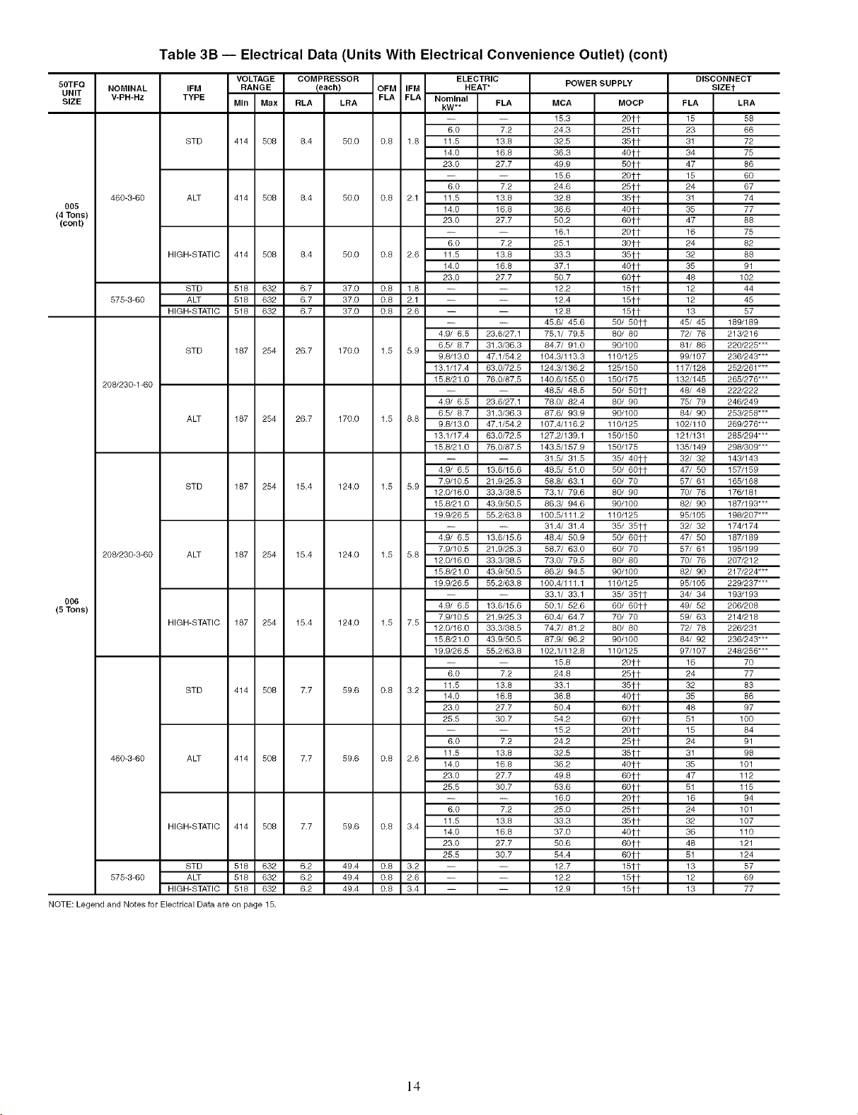
Table 3B -- Electrical Data (Units With Electrical Convenience Outlet) (cont)
50TFG
UNIT
SIZE
005
(4 Tons)
(cont)
006
(5 Tons)
NOTE: Legend and Notes for Electrical Data are on page 15.
NOMINAL
V-PH-Hz
460-3-60
575-3-60
208/230-1-60
208/230-3-60
460-3-60
575-3-60 ALT 518 632
IFM RANGE (each) OFM IFM HEAT*
TYPE MIn Max RLA LRA FLA FLA Nominal FLA
STD 414 508 6.4 50.0 0.8 1.8 11.5 13.8
ALT 414 508 6.4 50.0 0.8 2.1 11.5 13.6
HIGH-STATIC 414 508 6.4 50.0 0.8 2.6 11.5 13.8 33.3
STD 518 632 6.7 37.0 0.8 1.8 -- -- 12.2
ALT 518 632 6.7 37.0 0.6 2.1 -- -- 12.4
HIGH-STATIC 518 632 6.7 37.0 0.6 2.6 -- -- 12.8
STD 187 254 26.7 170.0 1.5 5.9
ALT 187 254 26.7 170.0 1.5 8.8
STD 187 254 15.4 124.0 1.5 5.9
ALT 167 254 15.4 124.0 1.5 5.6
HIGH-STATIC 187 254 15.4 124.0 1.5 7.5
STD 414 508 7.7
ALT 414 508 7.7
HIGH-STATIC 414 508 7.7
STD 518 632
HIGH-STATIC 518 632
VOLTAGE COMPRESSOR ELECTRIC
kW**
6.0 7.2
14.0 16.8
23.0 27.7
6.0 7.2
14.0 16.6 36.6
23.0 27.7 50.2
-- -- 16.1
6.0 7.2 25.1
14.0 16.8 37.1
23.0 27.7 50.7
-- -- 45.6/ 45.6
4.9/ 6.5 23.6/27.1 75.1/ 79.5
6.5/ 8.7 31.3/36.3 84.7/ 91.0
9.8/13.0 47.1/54.2 104.3/113.3
13.1/17.4 63.0/72.5 124.3/136.2
15.8/21.0 76.0/87.5 140.6/155.0
-- -- 48.5/ 48.6
4.9/ 6.5 23.6/27.1 78.0/ 82.4
6.5/ 8.7 31.3/36.3 87.6/ 93.9
9.8/13.0 47.1/54.2 107.4/116.2
13.1/17.4 63.0/72.5 127.2/139.1
15.8/21.0 76.0/87.5 143.5/157.9
-- -- 31.5/ 31.5
4.9/ 6.5 13.6/15.6 46.5/ 51.0
7.9/10.5 21.9/25.3 58.6/ 63.1
12.0/16.0 33.3/38.5 73.1/ 79.6
15.8/21.0 43.9/50.5 86.3/ 94.6
19.9/26.5 55.2/63.6 100.5/111.2
-- -- 31.4/ 31.4
4.9/ 6.5 13.6/15.6 48.4/ 50.9
7.9/10.5 21.9/25.3 58.7/ 63.0
12.0/16.0 33.3/38.5 73.0/ 79.5
15.8/21.0 43.9/50.5 86.2/ 94.5
19.9/26.5 55.2/63.6 100.4/111.1
-- -- 33.1/ 33.1
4.9/ 6.5 13.6/15.6 50.1/ 52.6
7.9/10.5 21.9/25.3 60.4/ 64.7
12.0/16.0 33.3/38.5 74.7/ 81.2
15.8/21.0 43.9/50.5 87.9/ 96.2
19.9/26.5 55.2/63.8 102.1/112.8
-- -- 15.8
6.0 7.2 24.8
59.6 0.8 3.2
59.6 0.8 2.6
59.6 0.8 3.4
6.2
49.4 0.8 3.2 -- -- 12.7
6.2
49.4 0.8 2.6 -- -- 12.2
6.2
49.4 0.8 3.4 -- -- 12.9
11.5 13.6 33.1
14.0 16.8 36.8
23.0 27.7 50.4
25.5 30.7 54.2
-- -- 15.2
6.0 7.2 24.2
11.5 13.8 32.5
14.0 16.8 36.2
23.0 27.7 49.8
25.5 30.7 53.6
-- -- 16.0
6.0 7.2 25.0
11.5 13.8 33.3
14.0 16.6 37.0
23.0 27.7 50.6
25.5 30.7 54.4
POWER SUPPLY
MCA MOCP
15.3 201-1-
24.3 251-1-
32.5 351-1-
36.3 401-1-
49.9 501-1-
15.6 2Ott
24.6 251-1-
32.8 351-1-
401-1-
601-1-
201-1-
301-1-
361-1-
401-1-
601-1-
16tt
16tt
16tt
5o/ 5ott
8o/ 80
9O/lOO
11o/125
125/15o
15o/175
5o/ 5ott
8o/ 90
9O/lOO
11o/125
15o/15o
15o/175
35/ 4ott
5o/6ott
60/ 70
80/ 90
90/100
110/125
35/ 351-1-
50/ 601-1-
60/ 70
80/ 80
90/100
110/125
35/ 351-1-
60/ 601-1-
70/ 70
80/ 80
90/100
110/125
201-1- 16 70
251-1- 24 77
351-1- 32 83
401-1- 35 86
601-1- 46 97
60tt 51 100
201-1- 15 84
251-1- 24 91
351-1- 31 98
401-1- 35 101
601-1- 47 112
601-1- 51 115
201-1- 16 94
251-1- 24 101
351-1- 32 107
401-1- 36 110
601-1- 48 121
601-1- 51 124
151-1- 13 57
151-1- 12 69
151-1- 13 77
DISCONNECT
SIZEt
FLA LRA
15 58
23 66
31 72
34 75
47 86
15 60
24 67
31 74
35 77
47 68
16 75
24 62
32 88
35 91
48 102
12 44
12 45
13 57
45/ 45 169/189
72/ 76 213/216
61/ 86 220/225"**
99/107 236/243"**
117/126 252/261"**
132/145 265/276"**
48/ 48 222/222
75/ 79 246/249
64/ 90 253/256"**
102/110 269/276"**
121/131 265/294"**
135/149 298/309"**
32/ 32 143/143
47/ 50 157/159
57/ 61 165/166
70/ 76 176/181
62/ 90 167/193"**
95/105 198/207"**
32/ 32 174/174
47/ 50 167/189
57/ 61 195/199
70/ 76 207/212
62/ 90 217/224"**
95/105 229/237"**
34/ 34 193/193
49/ 52 206/206
59/ 63 214/216
72/ 78 226/231
64/ 92 236/243"**
97/107 248/256"**
14
Page 15
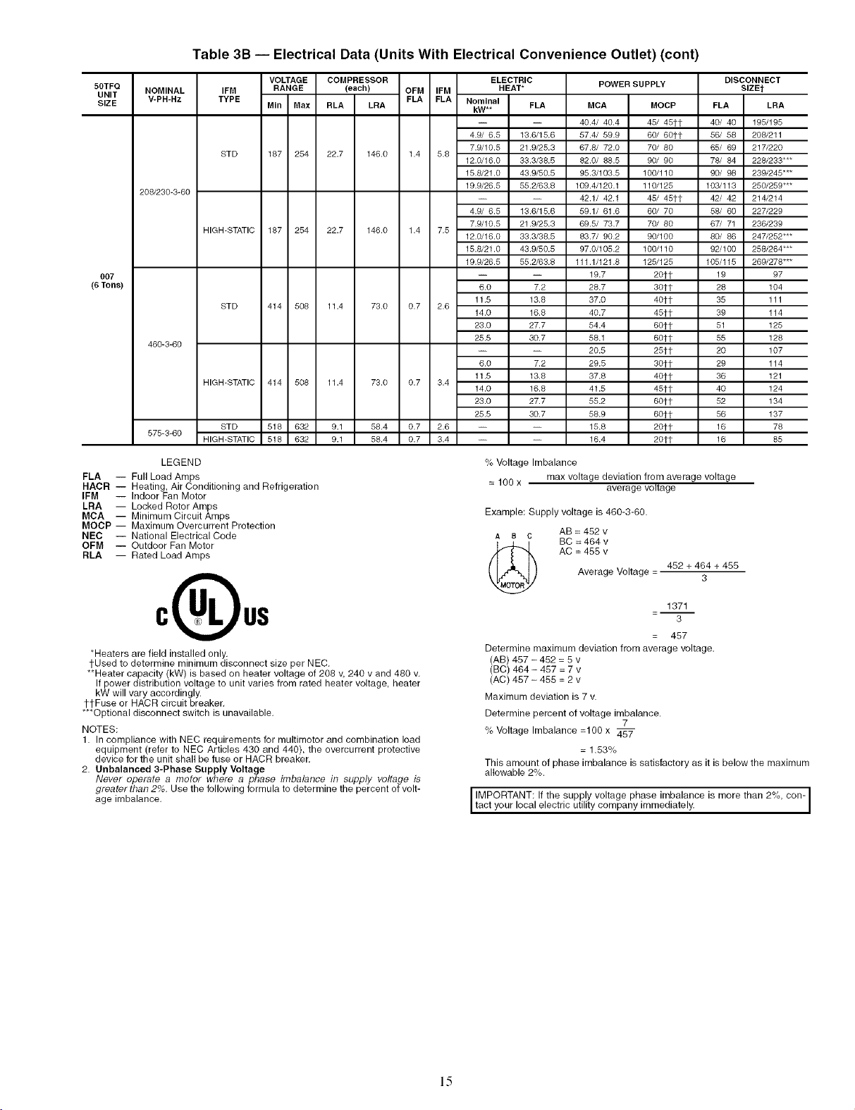
Table 3B -- Electrical Data (Units With Electrical Convenience Outlet) (cont)
50TFQ
UNIT
SIZE
007
(8 Tons)
NOMINAL
V-PH-Hz
208/230-3-60
460-3-60
575-3-60
IFM RANGE (each) OFM IFM HEAT*
TYPE MIn Max RLA LRA FLA FLA Nominal FLA
STD 187 254 22.7 146.0 1.4 5.8
HIGH-STATIC 187 254 22.7 146.0 1.4 7.5
STD 414 508 11.4 73.0 0.7 2.6
HIGH-STATIC 414 508 11.4 73.0 0.7 3.4
STD 518 632 9.1 58.4 0.7 2.6 -- --
HIGH-STATIC 518 632 9.1 58.4 0.7 3.4 -- --
LEGEND
FLA -- Full Load Amps
HACR -- Heating, Air Conditioning and Refrigeration
IFM -- Indoor Fan Motor
LRA -- Locked Rotor Amps
MCA -- Minimum Circuit Amps
MOCP -- Maximum Overcurrent Protection
NEC -- National Electrical Code
OFM -- Outdoor Fan Motor
RLA -- Rated Load Amps
VOLTAGE COMPRESSOR ELECTRIC
POWER SUPPLY
kW**
4.9/ 6.5 13.6/15.6
7.9/10.5 21.9/25.3
12.0/16.0 33.3/38.5
15.8/21.0 43.9/50.5
19.9/26.5 55.2/63.8
4.9/ 6.5 13.6/15.6
7.9/10.5 21.9/25.3
12.0/16.0 33.3/38.5
15.8/21.0 43.9/50.5
19.9/26.5 55.2/63.8
6.0 7.2
11.5 13.8
14.0 16.8
23.0 27.7
25.5 30.7
6.0 7.2
11.5 13.8
14.0 16.8
23.0 27.7
25.5 30.7
MCA MOCP
40.4/ 40.4 45/ 45tt
57.4/ 59.9 60/ 60tt
67.8/ 72.0 70/ 80
82.0/ 88.5 90/ 90
95.3/103.5 100/110
109.4/120.1 110/125
42.1/ 42.1 45/ 45tt
59.1/ 61.6 60/ 70
69.5/ 73.7 70/ 80
83.7/ 90.2 90/100
97.0/105.2 100/110
111.1/121.8 125/125
19.7 20tt
28.7 30it
37.0 40tt
40.7 45tt
54.4 6Oft
58.1 60it
20.5 25it
29.5 30it
37.8 40tt
41.5 45it
55.2 6Oft
58.9 6Oft
15.8 2Oft
16.4 20tt
% Voltage Imbalance
= 100 x max voltage deviation from average voltage
average voltage
Example: Supply voltage is 460-3-60.
A a C AB = 452 v
BC = 464 v
Average Voltage =
AC = 455 v
462 + 464 + 455
DISCONNECT
SlZEt
FLA LRA
40/ 40 195/195
56/ 58 208/211
85/ 89 217/220
78/ 84 228/233"**
90/ 98 239/245"**
103/113 250/259 ***
42/ 42 214/214
58/ 60 227/229
67/ 71 236/239
80/ 86 247/252"**
92/100 258/264"**
105/115 269/278"**
19 97
28 104
35 111
39 114
51 125
55 128
20 107
29 114
36 121
40 124
52 134
56 137
16 78
16 85
3
*Heaters are field installed only.
tUsed to determine minimum disconnect size per NEC.
**Heater capacity (kW) is based on heater voltage of 208 v, 240 v and 480 v.
If power distribution voltage to unit varies from rated heater voltage, heater
kW will vary accordingly.
ttFuse or HACR circuit breaker.
***Optional disconnect switch is unavailable.
NOTES:
1. In compliance with NEC requirements for multimotor and combination load
equipment (refer to NEC Articles 430 and 440), the overcurrent protective
device for the unit shall be fuse or HACR breaker.
2. Unbalanced 3-Phase Supply Voltage
Never operate a motor where a pbase imbalance in supply voltage is
greater than 2%. Use the following formula to determine the percent of volt-
age imbalance.
1371
=--
3
= 457
Determine maximum deviation from average voltage.
(AB) 457 - 452 = 5 v
(BC) 464 - 467 = 7 v
(AC) 467 - 466 = 2 v
Maximum deviation is 7 v.
Determine percent of voltage imbalance.
% Voltage Imbalance =100 x
7
= 1.63%
This amount of phase imbalance is satisfactory as it is below the maximum
allowable 2%.
IMPORTANT: If the supply voltage phase imbalance is more than 2%, con-
tact your local electric utility company immediately.
15
Page 16
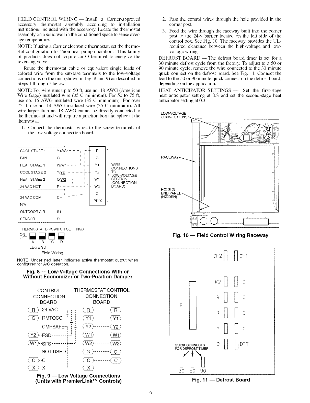
FIELD CONTROL WIRING -- Install a CmTier-approved
accessory thermostat assembly according to installation
instructions included with the accessory. Locate file thermostat
assembly on a solid wall in the conditioned space to sense aver-
age temperature.
NOTE: If using a Canier electronic thermostat, set the thermo-
stat configuration for "non-heat pump operation." This family
of products does not require an O terminal to energize the
reversing valve.
Route the thermostat cable or equivalent single leads of
colored wire from the subbase terminals to the low-voltage
connections on the unit (shown in Fig. 8 and 9) as described in
Steps 1 through 3 below.
NOTE: For wire runs up to 50 ft, use no. 18 AWG (American
Wire Gage) insulated wire (35 C minimum). For 50 to 75 ft,
use no. 16 AWG insulated wire (35 C minimum). For over
75 ft, use no. 14 AWG insulated wire (35 C minimum). All
wire lmger than no. 18 AWG cannot be directly connected to
the thermostat and will require a junction box and splice at the
thermostat.
1. Connect the thermostat wires to the screw terminals of
the low voltage connection board.
2. Pass the control wires through the hole provided in the
comer post.
3. Feed the wire through the raceway built into the corner
post to the 24-v banier located on the left side of the
control box. See Fig. 10. The raceway provides the UL-
required clearance between the high-voltage and low-
voltage wiring.
DEFROST BOARD- The defrost bomd timer is set for a
30 minute defrost cycle from the factory. To adjust to a 50 or
90 minute cycle, remove the wire connected to the 30 minute
quick connect on the defrost board. See Fig. 11. Connect the
lead to the 50 or 90 minute quick connect on the defrost board,
depending on the application.
HEAT ANTICIPATOR SETTINGS -- Set the first-stage
heat anticipator setting at 0.8 and set the second-stage heat
anticipator setting at 0.3.
LOW-VOLTAGE
CONNECTIONS _,
COOL STAGE 1
FAN
HEAT STAGE 1
COOL STAGE 2
HEAT STAGE 2
24 VAC HOT
24 VAC COM
N/A
OUTDOOR AIR $1
SENSOR S2
THERMOSTAT DIPSWlTCH SETTINGS
ON
A B C D
¢ m
Y1/W2 - - -I - R
G- i - G
W/W1- - 7 _- Y1
Y/Y2 - - r- - i- - Y2
O/W2- _ _- -i- - W1
R- " W2
I I
4
4 -- - C
IPD/X
WIRE
CONNECTIONS
TO
LOW-VOLTAGE
SECTION
(CONNECTION
BOARD)
LEGEND
FieldWiring
NOTE: Underlined letter indicates active thermostat output when
configured for A/C operation.
Fig. 8 -- Low-Voltage Connections With or
Without Economizer or Two-Position Damper
CONTROL
CONNECTION
BOARD
-24 VAC ..... ,--,--,
_-RMTOCC---' i
CMPSAFE-- , T
THERMOSTAT CONTROL
CONNECTION
BOARD
__,,
{3E>........
........{52}
i"
_-FSD .......... "
_-SFS
NOT USED
9) o o
RACBWAY_
HOLE IN
END PANEL_
(H;DDEN)
;; i;;] ........._ ......................... ...............
Fig. 10- Field Control Wiring Raceway
0F2_ _0F1
l]c
P1
QUICK CONNECTS
FOR DEFROST TIMER
@-C
{_}--X-
Fig. 9 -- Low Voltage Connections
(Units with PremierLink TM Controls)
{3E}
30 50 90
Fig. 11 -- Defrost Board
16
Page 17
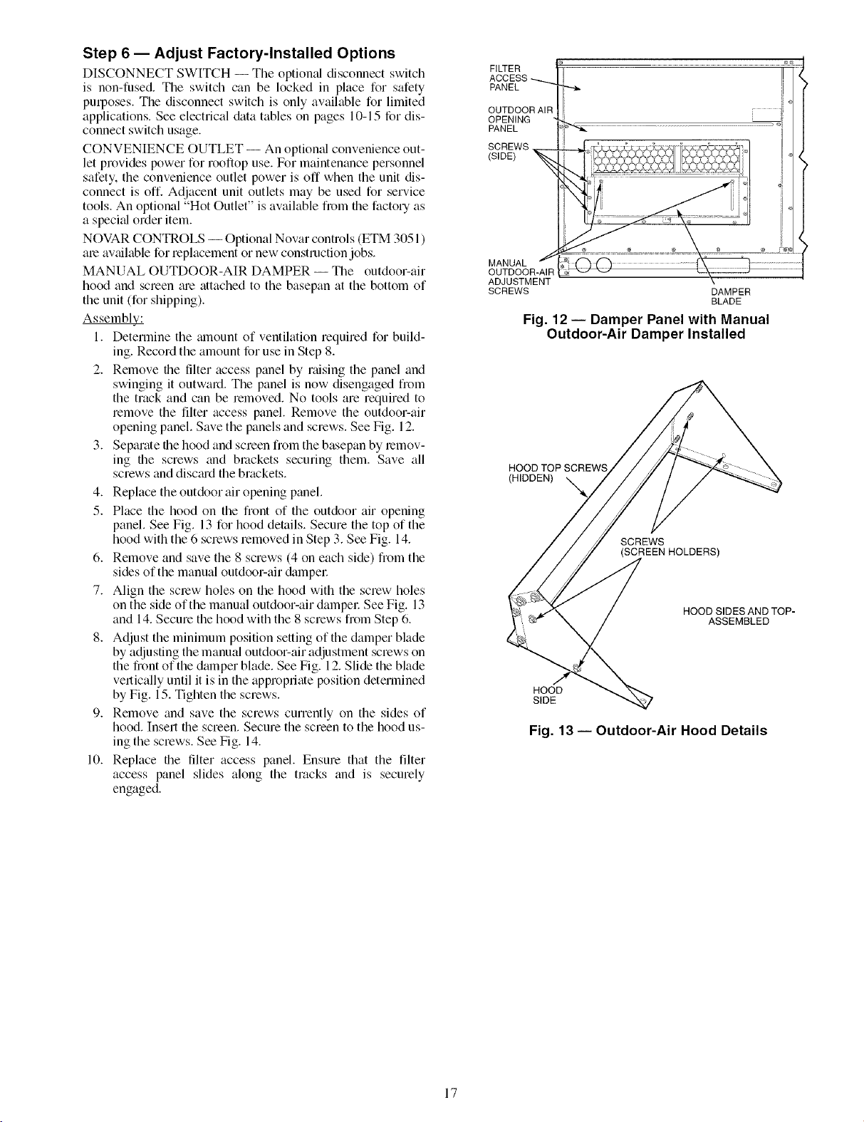
Step 6 -- Adjust Factory-Installed Options
DISCONNECT SWITCH -- The optional disconnect switch
is non-fused. The switch can be locked in place for safety
purposes. The disconnect switch is only available for limited
applications. See electrical &_ta tables on pages 10-15 for dis-
connect switch usage.
CONVENIENCE OUTLET -- An optiomd convenience out-
let provides power for rooftop use. For maintenance personnel
safety, the convenience outlet power is off when the unit dis-
connect is off. Adjacent unit outlets may be used for service
tools. An optional "Hot Outlet" is available from file factory as
a special order item.
NOVAR CONTROLS -- Optional Novar controls (ETM 3051 )
ale available for replacement or new construction jobs.
MANUAL OUTDOOR-AIR DAMPER -- The outdoor-air
hood and screen me attached to the basepan at the bottom of
the unit (for shipping).
Assembl£;.:
1. Determine the mnount of ventilation required for build-
ing. Record the amount for use in Step 8.
2. Remove the tilter access panel by raising the panel and
swinging it outward. The panel is now disengaged from
the track and can be removed. No tools are required to
remove the filter access panel. Remove the outdoor-air
opening panel. Save the panels and screws. See Fig. 12.
3. Separate the hood and screen from the basepan by lemov-
ing the screws and brackets securing them. Save all
screws and discm'd the brackets.
4. Replace the outdoor air opening panel.
5. Place the hood on the front of the outdoor air opening
panel. See Fig. 13 for hood details. Secure the top of the
hood with the 6 screws removed in Step 3. See Fig. 14.
6. Remove and save the 8 screws (4 on each side) from the
sides of the manual outdoor-air &_mpel:
7. Align the screw holes on the hood with the screw holes
on the side of the manual outdoor-air dampel: See Fig. 13
and 14. Secure the hood with the 8 screws from Step 6.
8. Adjust the minimum position setting of the damper blade
by adjusting the manual outdoor-air adjustment screws on
the front of the damper blade. See Fig. 12. Slide the blade
vertically until it is in the appropriate position determined
by Fig. 15. Tighten the screws.
9. Remove and save the screws currently on the sides of
hood. Insert the screen. Secure the screen to the hood us-
ing the screws. See Fig. 14.
10. Replace the tilter access panel. Ensure that the filter
access panel slides along the tracks and is securely
engaged.
FILTER
ACCESS
PANEL
OUTDOOR AIt
OPENING
PANEL
SCREWS
(SIDE) _ --
MANUAL _
OUTDOOR-AIR
ADJUSTMENT
SCREWS
Fig. 12 -- Damper Panel with Manual
Outdoor-Air Damper Installed
HOOD TOP SCREWS
(HIDDEN)
SCREWS
SCREEN HOLDERS)
HOOD SIDES AND TOP-
HOOD
SIDE
Fig. 13 -- Outdoor-Air Hood Details
DAMPER
BLADE
ASSEMBLED
17
Page 18

Fig. 14- Optional Manual Outdoor-Air
Damper with Hood Attached
1.0
/
0.8
LU
Pr
0.6
60
w
n_
o-
w
0.4
w
z
0.2
2 4 6 8 10 12
OUTDOORAIRFLOW (cfm x 100)
Fig. 15 -- Outdoor Air Damper Position Setting
PREMIERLINK TM CONTROL -- Tile PmmierLink control-
let is compatible with Cmrier Comfort Network® (CCN) de-
vices. This control is designed to allow users the access and
ability to change factory-defined settings, thus expanding the
function of the stan&ud unit control board. Cmrier's diagnostic
standard tier display tools such as Navigator TM or Scrolling
Marquee can be used with the PremierLink controllel:
/
The PremierLink controller (see Fig. 16 and 17) requires the
use of a C_rier electronic fllermostat or a CCN connection for
time broadcast to initiate its internal fimeclock. This is neces-
sary for broadcast of time of &ty functions (occupied/
unoccupied). No sensors tue supplied with the field-mounted
PremierLink control The factory-installed PremierLink con-
trol includes only the supply-air temperature (SAT) sensor and
the outdoor air temperature (OAT) sensor as standiud. An in-
door air quality (CO2) sensor can be added as an option. Refer
to Table 4 for sensor usage. Refer to Fig. 18 for PremierLink
controller wiring. The PremierLink control may be mounted in
the control panel or an area below the control panel.
NOTE: PmmierLink controller versions 1.3 and later am
shipped in Sensor mode. If used with a thermostat, the Pre-
mierLink controller must be configured to Thermostat mode.
Install the Supply Air Temperature (SAT) Sensor -- When
the unit is supplied with a factory-mounted PremierLink con-
trol, the supply-air temperature (SAT) sensor (33ZCSENSAT)
is factory-supplied and wired. The wiring is routed fl__)m file
PmmierLink control over the control box, through a grommet,
into the fan section, down _dong the back side of the fan, and
along the fan deck over to the supply-air opening.
The SAT probe is wire-tied to the supply-air opening (on the
horizontal opening end) in its shipping position. Remove the
sensor for installation. Re-position the sensor in file flange of
the supply-air opening or in the supply air duct (as required by
loc_d codes). Drill or punch a l/2-in, hole in the flange or duct.
Use two field-supplied, self-drilling screws to secure the sensor
probe in a horizontal orientation.
NOTE: The sensor must be mounted in the discharge airstmam
downstream of file cooling coil and any heating devices. Be
sure the probe tip does not come in contact wifll any of the unit
or heat surfaces.
Outdoor Air Temperature (OAT) Sensor -- When the unit is
supplied with a factory-mounted PremierLink control, the
ouMoor-air temperature (OAT) sensor is factory-supplied and
wired.
Install the Indoor Air Quality (CO 23 Sensor -- Mount the
optiomd indoor air quality (CO2) sensor according to manufac-
turer specifications.
A separate field-supplied transformer must be used to pow-
er the CO 2 sensor
Wire the CO 2 sensor to the COM and IAQI terminals of J5
on the PremierLink controllel: Refer to the PremierLink Instal-
lation, Start-up, and Configuration Instructions for detailed
wiring and configuration information.
18
Page 19

HVAC SENSOR INPUTS
SPACE TEMP x._
SET POINT "x_
SUPPLY AIR TEMP -_
OUTDOOR TEMP
INDOOR AIR QUALITY
OUTDOOR AIR QUALITY x_
DUAL MODE SENSOR/STAT
COMP SAFETY (Y1) _/_
FIRE SHUTDOWN (Y2)//_
SUPPLY FAN STATUS (Wl)
NOT USED (W2)/'_
ENTHALPY STATUS (ENTH) /'f
,,_ :.!o-oh._ ....:F] __ I11
........................." °_°............... UI
0
Fq _FI [] 0_1 ......_......_......f I
/ t / f "4 "-4 \
CCN/LEN
PORT
Fig. 16- PremierLink TM Controller
NAVIGATOR 4-20MA INDOOR COMPR HEAT EXHAUST
PORT ECONOMIZER FAN MOTOR 1 & 2 LOW/HIGH RVS VALVE
OUTPUTS
PREMIERLINK
CONTROL
HINGED
DOOR
PANEL
_.L L J
=i;:]r ]r_i
©©
/
o
Fig. 17 -- PremierLink Controller (Installed)
19
Page 20
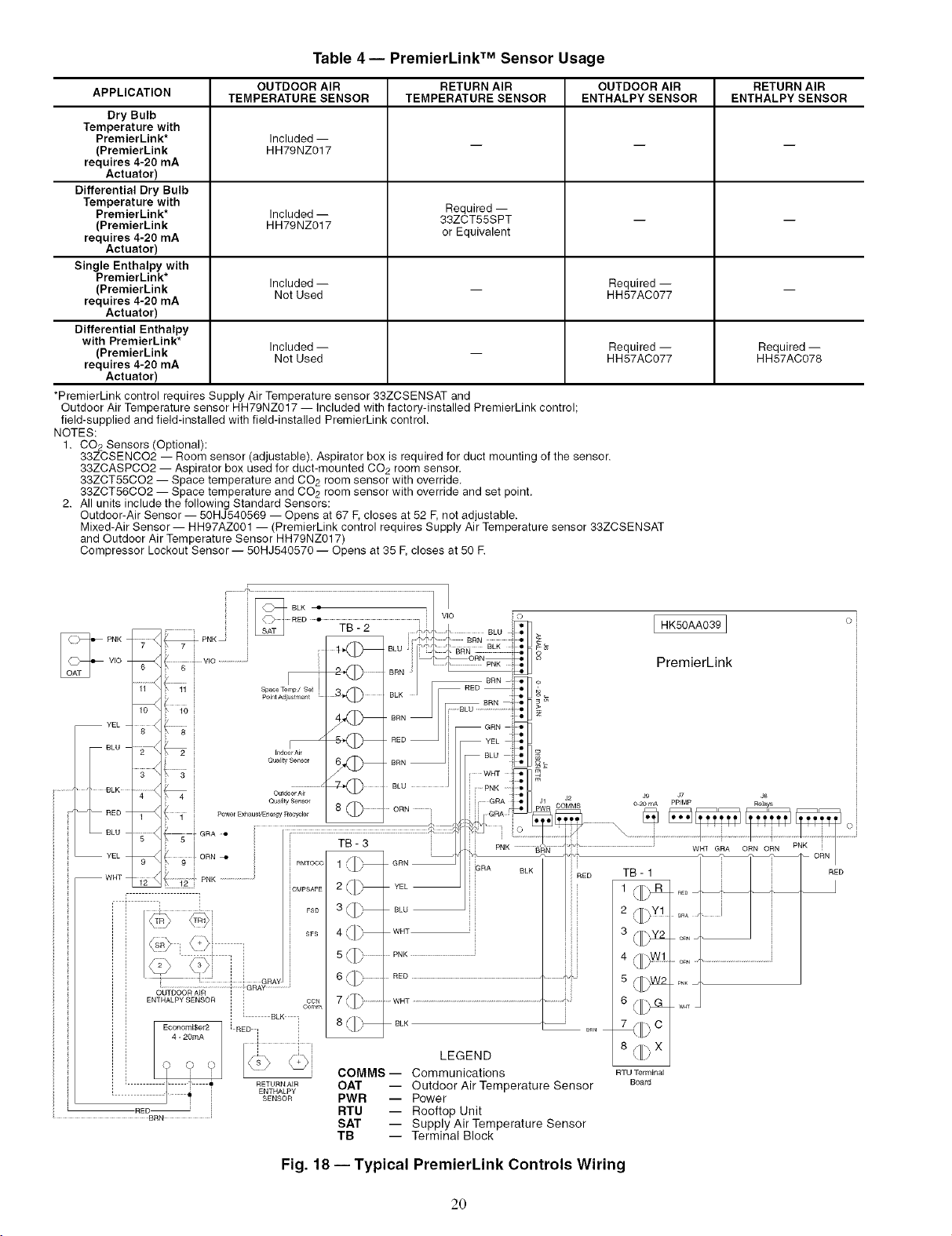
Table 4-- PremierLink TM Sensor Usage
APPLICATION TEMPERATURE SENSOR TEMPERATURE SENSOR ENTHALPY SENSOR ENTHALPY SENSOR
Dry Bulb
Temperature with
PremierLink* Included --
(PremierLink HH79NZ017
requires 4-20 mA
Actuator)
Differential Dry Bulb
Temperature with Required --
PremierLink* Included -- 33ZCT55SPT -- --
(PremierLink HH79NZ017
requires 4-20 mA or Equivalent
Actuator)
Single Enthalpy with
PremierLink*
(PremierLink Included -- _ Required -- _
requires 4-20 mA
Actuator)
Differential Enthalpy
with PremierLink*
(PremierLink Included -- _ Required -- Required --
requires 4-20 mA
Actuator)
*PremierLink control requires Supply Air Temperature sensor 33ZCSENSAT and
Outdoor Air Temperature sensor HH79NZ017 -- Included with factory-installed PremierLink control;
field-supplied and field-installed with field-installed PremierLink control.
NOTES:
1. CO2 Sensors (Optional):
33ZCSENCO2 -- Room sensor (adjustable). Aspirator box is required for duct mounting of the sensor.
33ZCASPCO2 -- Aspirator box used for duct-mounted CO2 room sensor.
33ZCT55CO2 -- Space temperature and CO2 room sensor with override.
33ZCT56CO2 -- Space temperature and CO2 room sensor with override and set point.
2. All units include the following Standard Sensors:
Outdoor-Air Sensor -- 50HJ540569 -- Opens at 67 F,closes at 52 F,not adjustable.
Mixed-Air Sensor- HH97AZ001 -- (PremierLink control requires Supply Air Temperature sensor 33ZCSENSAT
and Outdoor Air Temperature Sensor HH79NZ017)
Compressor Lockout Sensor -- 50HJ540570 -- Opens at 35 E closes at 50 R
OUTDOOR AIR RETURN AIR OUTDOOR AIR RETURN AIR
Not Used HH57AC077
Not Used HH57AC077 HH57AC078
' PNK _REB " TB-2 _i2Z BnNEmO:_
VIO
LZ2vo....................i LOJil
PNK
YEL
BLU
io i 4_f_hj BRN_ [ BLU .....................ie_[J _
i ......... • _ BLU I
'_ BLK
_ BLU
.... _ i GR_o ...............................................................................................
YEL
RED
WHT
_2 _ PNK ........................ 2/_h
I I
T :::::i i
. i]]]]]]]] RETURNAIRENTHALPY
RED
i Quality Sensor 8
_ i ORN
1 i P°We/Exhau_VEnelgy Recyc]e _ i
, J
: 1 TB-3 j
ORN -m i /
9 i _ RMTOCC 1 _/_ GRN
Economi$er2 [ RED I i
4 - 20mA i i i
c) O () x /i
BRN
i t BLK
= SENSOR
= BED BRN- o
CMPSAFE _[[_ YEL
BLU
WHT
.... PNK ..............................................
RED _ •
....w.z..........................................................................................................i,i
BLK
Cemm
FSO
SFS
CON
3 {][___
4 {11_--
5(][)............
6 (111)
7 (._, ............
8(11)--
LEGEND
COMMS -- Communications
OAT -- Outdoor Air Temperature Sensor
PWR -- Power
RTU -- Rooftop Unit
SAT -- Supply Air Temperature Sensor
TB -- Terminal Block
HK50AA039]
o i
PremierLink
• ORN ......................................................
\[L/
PNK
!
6(i)
7 /'hC
w_
8 /1[_ X
RTU Terminal
Board
Fig. 18 --Typical PremierLink Controls Wiring
20
Page 21

Enthalpy Sensors and Control -- Tile enthalpy control
(HH57AC077) is supplied as a field-inst_dled accessory to be
used with the EconoMiSer2 damper control option. The out-
door air enthalpy sensor is part of file enfllalpy control. The
separate field-installed accessory return air enthalpy sensor
(HH57AC078) is required for differential enthalpy control
NOTE: The enthalpy control must be set to the "D" setting for
differential enthalpy control to work properly.
The enthalpy control receives the indoor and return
enthalpy fiom the outdoor and return tfir enthalpy sensors and
provides a @ contact switch input to the PremierLinld TM
controllel: Ix_cate the controller in place of an existing econo-
mizer controller or near the actuatol: The mounting plate may
not be needed if existing bracket is used.
A closed contact indicates that outside air is preferred to the
return ail: An open contact indicates that file economizer
should remtfin at minimum position.
Outdoor Air Enthalpy Sensor/Enthalpy Controller
(HH57AC077) -- To wile the outdoor air enthalpy sensol;
perform the following (see Fig. 19 and 20):
NOTE: The outdoor air sensor can be removed from the back
of file enthalpy controller and mounted remotely.
1. Use a 4-conductor, 18 or 20 AWG cable to connect the
enthalpy control to the PlemierLink controller and power
transforme_:
2. Connect the following 4 wires from the wire harness
located in rooftop unit to the enth_dpy controller:
a. Connect the BRN wire to the 24 vac terminal (TRI)
on enthalpy control and to pin 1 on 12-pin harness.
b. Connect the RED wire to the 24 vac GND termimd
(TR) on enthalpy sensor and to pin 4 on 12-pin
harness.
c. Connect the GRAY/ORN wire to J4-2 on Premier-
Link controller and to termimd (3) on enth_dpy sensol:
d. Connect the GRAY/RED wire to J4-1 on Premier-
Link controller and to termimd (2) on enthalpy sensol:
NOTE: [f installing in a Canier rooftop, use the two gray wires
provided from the control section to the economizer to connect
PremierLink controller to termin_ds 2 and 3 on enthalpy sensol:
Return Air Enthalpy Sensor -- Mount the return-air enthalpy
sensor (HH57AC078) in file return-air duct. The return tfir
sensor is wired to the enthalpy controller (HH57AC077). The
outdoor enthalpy changeover set point is set at the controller
To wire the return air enthalpy sensol: perform the follow-
ing (see Fig. 19):
1. Use a 2-conductor, 18 or 20 AWG, twisted pair cable to
connect the return air enthalpy sensor to the enthalpy
controllec
2. At the enthalpy control remove the factory-installed
resistor from the (SR) and (+) terminals.
3. Connect the field-supplied RED wire to (+) spade
connector on the return air enthalpy sensor and the (SR+)
terminal on the enthalpy controllel: Connect the BLK
wire to (S) spade connector on the return _fir enthalpy
sensor and the (SR) terminal on the enthalpy controller.
ENTHALPY CONTROLLER
A(_)C TRr"_TRI[_- BRN
sorh +E3
SRI-h÷ID-i-i '
LED
NOTES:
1. Remove factory-installed jumper across SR and + before con-
necting wires from return air sensor.
2. Switches shown in high outdoor air enthalpy state. Terminals 2
and 3 close on low outdoor air enthalpy relative to indoor air
enthalpy.
3. Remove sensor mounted on back of control and locate in out-
side airstream.
RED
BLK SENSOR)
RED
GRAY/ORN
GRAY/RED JIN UNIT
AIR
[_S (OUTDOOR
LWIRE HARNESS
+ ENTHALPY
i"_ S (RETURN AIR
[] + ENTHALPY
SENSOR)
Fig. 19 -- Outdoor and Return Air Sensor Wiring
Connections for Differential Enthalpy Control
HH57AC077
ENTHALPY
CONTROL AND
OUTDOOR AIR
ENTHALPY SENSOR
o o
SENSOR (USED WITH
ENTHALPY CONTROL
FOR DIFFERENTIAL
ENTHALPY OPERATION)
HH57AC078 ENTHALPY
÷ MOUNTING PLATE
Fig. 20 -- Differential Enthalpy Control,
Sensor and Mounting Plate (33AMKITENT006)
€
21
Page 22
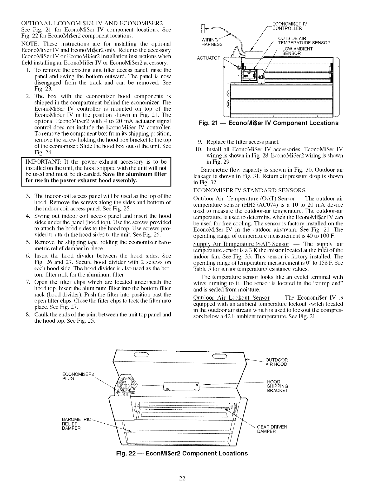
OPTIONAL ECONOMI$ER IV AND ECONOMI$ER2 --
See Fig. 21 for EconoMiSer IV component locations. See
Fig. 22 for EconoMiSer2 component locations.
NOTE: These instructions are for installing the optional
EconoMiSer IV and EconoMiSer2 only. Refer to the accessory
EconoMiSer IV or EconoMi$er2 inst¢fllafion instructions when
field installing an EconoMiSer IV or EconoMiSer2 accessory.
1. To remove the existing unit filter access panel, raise the
panel and swing the bottom outwCud. Tile panel is now
disengaged fiom the track and can be removed. See
Fig. 23.
2. The box with the economizer hood components is
shipped in the compartment behind the economizel: The
EconoMiSer IV controller is mounted on top of the
EconoMi$er IV in the position shown in Fig. 21. The
optional EconoMiSer2 with 4 to 20 mA actuator signal
control does not include the EconoMiSer IV controllel:
To remove the component box from its shipping position,
remove the screw holding the hood box bracket to the top
of the economizer Slide the hood box out of the unit. See
Fig. 24.
IMPORTANT: If the power exhaust accessory is to be ]
inst_flled on the unit, the hood shipped with the unit will not
be used and must be discarded. Save the aluminum filter
for use in the power exhaust hood assembly.
3. The indoor coil access panel will be used as the top of the
hood. Remove the screws along the sides and bottom of
the indoor coil access panel. See Fig. 25.
4. Swing out indoor coil access panel and insert the hood
sides under the panel (hood top). Use the screws provided
to attach the hood sides to the hood top. Use screws pro-
vided to attach the hood sides to the unit. See Fig. 2(3.
5. Remove the shipping tape holding the economizer baro-
metric relief &_mper in place.
6. Insert the hood divider between the hood sides. See
Fig. 2(3 and 27. Secure hood divider with 2 screws on
each hood side. The hood divider is also used as the bot-
tom filter rack for the aluminum filtec
7. Open the filter clips which _ue located underneath the
hood top. Insert the aluminum filter into the bottom filter
rack (hood divider). Push the filter into position past the
open filter clips. Close the filter clips to lock the filter into
place. See Fig. 27.
8. Caulk the ends of the joint between the unit top panel and
the hood top. See Fig. 25.
I
ECONOMI$ER IV
/--CONTROLLER
OUTSIDE AIR
12i/_R'it4"E_SS _@_ STEMPERATURE SENSOR
/ /_LOW AMBIENT
/ 0
a ¢ .-J
Fig. 21 -- EconoMiSer IV Component Locations
9. Replace the filter access panel.
10. Install all EconoMi$er IV accessories. EconoMi$er IV
wiring is shown in Fig. 28. EconoMi$er2 wiring is shown
in Fig. 29.
Barometric flow capacity is shown in Fig. 30. Outdoor air
leakage is shown in Fig. 31. Return air pressure diop is shown
in Fig. 32.
ECONOMI$ER IV STANDARD SENSORS
Outdoor Air Temperature (OAT) Sensor -- The outdoor air
temperature sensor (HH57AC074) is a 10 to 20 mA device
used to measure the outdoo>air temperature. The outdoo>air
temperature is used to detemfine when the EconoMiSer IV can
be used for free cooling. The sensor is factory-installed on the
EconoMiSer IV in the outdoor airstream. See Fig. 21. The
operating range of temperature measurement is 40 to 100 E
Supply Air Temperature (SAT) Sensor -- The supply air
tempemlure sensor is a 3 K thermistor located at the inlet of the
indoor fan. See Fig. 33. This sensor is factory installed. The
operating range of temperature measurement is 0° to 158 F. See
Table 5 for sensor temperature/resistance values.
The temperature sensor looks like an eyelet terminal with
wires running to it. The sensor is located in the "crimp end"
and is sealed from moisture.
Outdoor Air Lockout Sensor -- The EconomiSer IV is
equipped with an ambient temperature lockout switch located
in the outdoor air stream which is used to lockout the compres-
sors below a 42 F ambient temperature. See Fig. 21.
ECONOMI$ER2
PLUG
BAROMETRIC
RELIEF
DAMPER
CCCb
_ UTDOOR
t_
Fig. 22 -- EconMiSer2 Component Locations
22
AIR HOOD
HOOD
SHIPPING
BRACKET
__- GEAR DRIVEN
DAMPER
Page 23
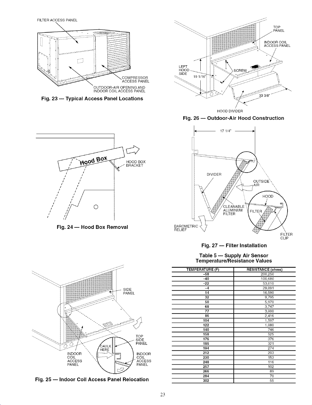
FILTER ACCESS PANEL
COMPRESSOR
ACCESS PANEL
OUTDOOR-AIR OPENING AND
INDOOR COILACCESS PANEL
Fig. 23 -- Typical Access Panel Locations
HOOD BOX
INDOOR COIL
ACCESS PANEL
LEFT
SIDE
33 3/8"
HOOD DIVIDER
Fig. 26 -- Outdoor-Air Hood Construction
17 1/4"
TOP
PANEL
//
i I
I
i!
I
i I
I
I
I
I
I
I
/
/
O
Fig. 24- Hood Box Removal
SIDE
PANEL
--_ TOP
PANEL
INDOOR
COIL
ACCESS
PANEL
INDOOR
COIL
PANEL
Fig. 25 -- Indoor Coil Access Panel Relocation
DIVIDER
BAROMETRIC
RELIEF
Fig. 27 -- Filter Installation
Table 5 -- Supply Air Sensor
Temperature/Resistance Values
TEMPERATURE (F) RESISTANCE (ohms)
-58 200,250
-40 100,680
-22 53,010
-4 29,091
14 18,590
32 9,795
50 5,970
68 3,747
77 3,000
86 2,418
104 1,597
122 1,080
140 748
158 525
176 378
185 321
194 274
212 203
230 153
248 118
257 102
266 89
284 70
302 55
FILTER
CLIP
23
Page 24

(FIELD
ACCESSORY)
REMOTE MIN
POSITION POT
IRZ'H0_POT(135 0_)-
OAT TEMPI t
ZNTHALPY SENSOR
RED-
(FIELD ACCESSORY)
RATIENTHALPY SENSOR
BLK_
LEGEND
DCV-- Demand Controlled Ventilation
IAQ -- Indoor Air Quality
LA -- Low Ambient Lockout Device
OAT-- Outdoor-Air Temperature
POTI Petentiometer
RAT -- Return-Air Temperature
FOR OCCUPANCY CONTROL
REPLACE JUMPER WITH
FIELD-SUPPLIED TIME CLOCK
BLK
-]
2V IOV
ZXH BOARD
_)_ ECONOMIRER IV
OPEN
2V ION 0
2V ]OV
Potentiometer Defaults Settings:
Power Exhaust Middle
Minimum Pos. Fully Closed
DCV Max, Middle
DCV Set Middle
Enthalpy C Setting
!4V(z¢
FIELD SPLICE
TAR
TO PWR EXHAUST
ACCESSORY
NOTES:
2. If a separate field-supplied 24 v transformer is used for the IAQ sensor power
3. Fer field-installed remote minimum position POT, remove black wire jumper
BLK
ECONOMIZER MOTOR
WHT_
RED
8L_
PL6-R
FOR STD
UNIT
_a<
I DRYJ
I
_ -BRN
1. 620 ohm, 1 watt 5% resistor should be removed only when using differential
enthalpy or dry bulb.
YELBLu_LA
FIELD SPLICE
GRY
OR6
supply, it cannot have the secondary of the transformer grounded,
between P and P1 and set control minimum position POT to the minimum
position.
u
(NOT USED)
(NOT USED1 I_
D_
B<
(NOT USED)
B_
(NOT USED)
Fig. 28 -- EconoMi$er IV Wiring
I
BLACK
500 OHM
NOTE 1
NOTE3
50HJ540573
ACTUATOR
ASSEMBLY
RESISTOR-'?
RUN
J
DIRECT DRIVE
ACTUATOR
[- I
.eIl_
+e- I
OPTIONAL C02
SENSOR 4 - 20 mA
OUTPUT
I
I
I
I
VIOLET
PINK
s
w
>-
WHITE
NOTES:
1. Switch on actuator must be in run position for economizer to operate.
2. PremierLink TM control requires that the standard 50HJ540569 outside-air sensor be replaced by either the CROASENR001A00 dry bulb sensor or HH57A077
enthalpy sensor.
3. 50HJ540573 actuator consists of the 50HJ540567 actuator and a harness with 500-ohm resistor.
4
3
5
2
8
6
7
RED
1
10
11
9
12
ECONOMIZER2 PLUG
Fig. 29 -- EconoMi$er2 with 4 to 20 mA Control Wiring
24
Page 25

2500
w
z 2000
w 1500
w
w 1000
L
m 500
©
Z
-- 0
S
L
iii i i i _ i i i i i i i i i
0.05 0115 0.25
STATIC PRESSURE (in. wg)
Fig. 30 -- Barometric Flow Capacity
"5
30
LU
p-
25
££ 20
LU
I-- 15
LU
LU
EL 10
©
5
©
z 0
0.13 0.20 0.22 0.25 0.30 0.35 0.40 0.45 0.50
o
LL
ff
STATIC PRESSURE (in. wg)
Fig. 31 -- Outdoor-Air Damper Leakage
eooe
w
D 5000
Z
4000
w
3000
w
w
L
2000
1000
0
S
L
0.05 0.10 0.15 0.20 0.25 0.30 0.35
STATIC PRESSURE (in. wg)
Fig. 32 -- Return-Air Pressure Drop
J
/
SUPPLY AIR
TEMPERATURE
SENSOR
MOUNTING
LOCATION _,
SUPPLY AIR
TEMPERATURE
SENSOR
Fig. 33 -- Supply Air Sensor Location
ECONOMISER IV CONTROL MODES
IMPORTANT: The optional EconoMiSer2 does not
include a controllel: The EconoMiSer2 is operated by a 4 to
20 mA signal from an existing field-supplied controller
(such as PremierLink TM control). See Fig. 29 for wiring
information.
Determine the EconoMiSer IV control mode before set up of
the control. Some modes of operation may require different sen-
sors. Refer to Table 6. The EconoMiSer IV is supplied from the
factoly with a supply air temperature sensor and an outdoor air
temperature sensor This allows for operation of the
EconoMiSer IV with outdoor air dry bulb changeover control.
Additional accessories can be added to allow for different types
of changeover control and operation of the EconoMiSer IV and
unit.
Outdoor Dl7 Bulb Changeover -- The standard controller is
shipped from the factoq configured for outdoor @ bulb
changeover control. The outdoor air and supply air temperature
sensors we included as standtu:d. For this control mode, the
outdoor temperature is compared to an adjustable set point
selected on the control. If the outdoor-air temperature is above
the set point, the EconoMiSer IV will adjust the outdoor-air
&_mpers to minimum position. If the outdoor-air temperature is
below the set point, the position of the outdoor-air dampers will
be controlled to provide free cooling using outdoor ail: When
in this mode, the LED next to the free cooling set point potenti-
ometer will be on. The changeover temperature set point is
controlled by the free cooling set point potentiometer located
on the control. See Fig. 34. The sc_de on the potentiometer is A,
B, C, and D. See Fig. 35 for the corresponding temperature
changeover values.
Differential Dry Bulb Control -- For differential dry bulb
control the sttmdard outdoor &y bulb sensor is used in conjunc-
tion with an additional accessory dry bulb sensor (part number
CRTEMPSN002A00). The accessoq sensor must be mounted
in the return airstream. See Fig. 36. Wiring is provided in the
EconoMiSer IV wiring htuness. See Fig. 28.
In this mode of operation, the outdoor-air temperature is
compared to the return air temperature and the lower tempera-
ture airstream is used for cooling. When using this mode of
changeover control, turn the enthalpy set point potentiometer
fully clockwise to the D setting. See Fig. 34.
Table 6 -- EconoMi$er IV Sensor Usage
APPLICATION
ECONOMI$ER IV WITH OUTDOOR AIR
Outdoor Air
Dry Bulb
Differential
Dry Bulb
Single Enthalpy
Differential
Enthalpy
CO 2 for DCV
Control using a
Wall-Mounted
CO2 Sensor
CO 2 for DCV
Control using a
Duct-Mounted
CO2 Sensor
33ZCSENCO21-
33ZCASPCO2**
*CRENTDIF004A00 and CRTEMPSN002A00 accessories are
used on many different base units. As such, these kits may con-
tain parts that will not be needed for installation.
1-33ZCSENCO2 is an accessory CO 2 sensor.
**33ZCASPCO2 is an accessory aspirator box required for duct-
mounted applications.
1-1-CRCBDIOX005A00 is an accessory that contains both
33ZCSENCO2 and 33ZCASPCO2 accessories.
DRY BULB SENSOR
Accessories Required
None. The outdoor air dry bulb sensor
is factory installed.
CRTEMPSN002A00*
HH57AC078
HH57AC078
and
CRENTDIF004A00*
33ZCSENCO2
and CRCBDIOX005A001-1-
25
Page 26

EXHAUST
FAN SET POINT
LED LIGHTS
WHEN EXHAUST
CONTACT IS MADE
MINIMUM DAMPER
POSITION SETTING
MAXIMUM DAMPER _
DEMAND CONTROL
VENTILATION SET POINT
LED LIGHTS WHEN
DEMAND CONTROL
VENTILATION INPUT
IS ABOVE SET POINT
DEMAND CONTROL
VENTILATION SET POINT
LED LIGHTS WHEN
OUTDOOR AIR IS
FREE COOLING
SUITABLE FOR
CHANGEOVER SET POINT
ENTHALPY
Fig. 34 -- EconoMi$er IV Controller Potentiometer
and LED Locations
19
LED ION
17
16- -- - LED OFI
15
13
12
11
10
9
40 45 50
LED ON
55 60 65
DEGREES FAHRENHEIT
LED O;
'_-_ .LED ON- --
70 75 80 85 90 95 100
Fig. 35 -- Outside Air Temperature
Changeover Set Points
ECONOMISER IV
CONTROLLER
ECONOMI$ER
SENSOR
LE]_ _- RETURNAIR
RETURN DUCT
(FIELD-PROVIDED)
Fig. 36 -- Return Air Temperature or Enthalpy
Sensor Mounting Location
Outdoor Enthalpy Changeover -- For enthalpy control, ac-
cessory enthalpy sensor (part number HH57AC078) is le-
quired. Replace the stan&u'd outdoor dry bulb temperature sen-
sor with the accessory enth_dpy sensor in the same mounting
location. See Fig. 21. When the outdoor air enth_dpy rises
above the outdoor enthalpy changeover set point, the outdoor-
air damper moves to its minimum position. The outdoor
enthalpy changeover set point is set with the outdoor enth_dpy
set point potentiometer on the EconoMiSer IV controllel: The
set points are A, B, C, and D. See Fig. 37. The factory-installed
620-ohm jumper must be in place across terminals SR and SR+
on the EconoMiSer IV controllec See Fig. 21 and 38.
Differential Enthalpy Control -- For differential enthalpy
control, the EconoMiSer IV controller uses two enthalpy sen-
sors (HH57AC078 and CRENTDIF004A00), one in the out-
side air and one in the return air duct. The EconoMiSer IV
controller comptues the outdoor air enthalpy to the return air
enthalpy to determine EconoMiSer IV use. The controller
selects the lower enth_dpy air (return or outdoor) for cooling.
For example, when the outdoor air has a lower enthalpy than
the return air. the EconoMiSer IV opens to bring in outdoor air
for free cooling.
Replace the standard outside air dry bulb temperature sen-
sor with the accessory enthalpy sensor in the same mounting
location. See Fig. 21. Mount the return air enthalpy sensor in
the return air duct. See Fig. 36. Wiring is provided in the
EconoMiSer IV wiring harness. See Fig. 28. The outdoor en-
thalpy changeover set point is set with the outdoor enthalpy set
point potentiometer on the EconoMiSer IV controllec When
using this mode of changeover control, turn the enthalpy set
point potentiometer fully clockwise to the D setting.
Indoor Air Quality (IAQ) Sensor Input -- The IAQ input
can be used for demand control ventilation control based on the
level of CO 2 measured in the space or return air duct.
Mount the accessory IAQ sensor according to manufacturer
specifications. The IAQ sensor should be wired to the AQ and
AQI terminals of the controllec Adjust the DCV potentiome-
ters to correspond to the DCV voltage output of the indoor air
qu_dity sensor at the user-determined set point. See Fig. 39.
If a separate field-supplied transformer is used to power the
IAQ sensm; the sensor must not be grounded or the
EconoMiSer IV control bo_ud will be &tmaged.
Exhaust Set Point Adjustment -- The exhaust set point will
determine when the exhaust fan runs based on damper position
(if accessory power exhaust is installed). The set point is modi-
fied with the Exhaust Fan Set Point (EXH SET) potentiometer.
See Fig. 34. The set point represents the damper position above
which the exhaust fans will be turned on. When there is a call
for exhaust, the EconoMiSer IV controller provides a 45 _+15
second delay before exhaust fan activation to allow the damp-
ers to open. This delay allows the &tmper to reach the appro-
priate position to avoid unnecessary fan overload.
Minimum Position Control -- There is a minimum dmnper
position potentiometer on the EconoMiSer IV controllec See
Fig. 34. The minimum dmnper position mainttfins the mini-
mum airflow into the building during the occupied period.
When using demand ventilation, the minimum &_mper po-
sition represents the minimum ventilation position for VOC
(volatile organic compound) ventilation requirements. The
maximum demand ventilation position is used for fully occu-
pied ventilation.
When demand ventilation control is not being used, the
minimum position potentiometer should be used to set the oc-
cupied ventilation position. The maximum demand ventilation
position should be turned fully clockwise.
Adjust the minimum position potentiometer to _dlow the
minimum amount of outdoor air. as required by local codes, to
enter the building. Make minimum position adjustments with
at least 10 F temperature difference between the outdoor and
return-air temperatures.
26
Page 27

85 90 95 100 105 110
(29) (32) (35) (38) (41) (43)
CONTROL CONTROL POINT
CURVE APPROX °F (°C)
AT 50% RH
A 73 123)
B 70{21)
C 67 (19)
O 63 (17)
35 40 45 50 55 60 65 70 75 80 85 90 95 100 105 110
(2) (4) (7) (10) (13) (16) (18) (21) (24) (27) (29) (32) (35) (38) (41) (43)
APPROXIMATE DRY BULB TEMPERATURE-- °F (°C)
Fig. 37 -- Enthalpy Changeover Set Points
/ I/\
HIGH LIMIT
CURVE
-- N1 EXH
q N _l_Ji 2VXCCJ110V
N P1 r_EXP_
V
IHI_ II T_
Vac COM
24T_24 Vac
HO V
/ T1 N
/U T_-J Open
2
i
_,Q1 DCV
D AOD%v
nso+n2v 0ve'
_ soLI
SR+ Free
In nooo,©
SR__J B C
L21PJ.....
i /Yo
Fig. 38 -- EconoMi$er IV Control
To determine the minimum position setting, perform the
following procedure:
1. Calculate the appropriate mixed air temperature using the
following formula:
OA RA
(Tox _) + (TR x I--"_T)=TM
To = Outdoor-Air Temperature
OA = Percent of Outdoor Air
TR = Return-Air Temperature
RA = Percent of Return Air
TM = Mixed-Air Temperature
5
......_ 4
EF_ EF1
i
i
i
i
i
i
&
z
_o
CE
S
LT_
Z
8
LU
_3
z
c£
6000
5000
4000
3000
2000
1000
<
CO 2 SENSOR MAX RANGE SEqq-ING
+ 800 ppm
t l000 ppm
+1100 ppm
___ + 9oo ppm
2 3 4 5 6 7 8
DAMPER VOLTAGE FOR MAX VENTILATION RATE
Fig. 39 -- 002 Sensor Maximum Range Setting
As an example, if local codes require 10% outdoor air
during occupied conditions, outdoo>air temperature is
60 F. and return-air temperature is 75 E
(60 x.l 0) + (75 x .90) = 73.5 F
2.
Disconnect the supply air sensor fi_m terminals T and
TI.
3.
Ensure that the factou-installed jumper is in place across
terminals P and PI. ff remote damper positioning is being
used, make sure that the terminals are wired according to
Fig. 28 and that the minimum position potentiometer is
turned fully clockwise.
27
Page 28

4.
Connect 24 vac acloss terminals TR and TRI.
5.
Carefiflly adjust the minimum position potentiometer
until the measured mixed-air temperature matches the
calculated value.
6. Reconnect the supply air sensor to termin_ds T and TI.
Remote control of the EconoMiSer IV dalnper is desilable
when requiring additional tempormy ventilation. If a field-
supplied remote potentiometer (Honeywell part number
$963B1128) is wired to the EconoMiSer IV controller, the
minimum position of the &tmper can be controlled from a
remote location.
To control the minimum damper position lemotely, remove
the factory-installed jumper on the P and PI terminals on the
EconoMiSer IV controllel: Wire the field-supplied potentiolne-
ter to the P and PI terminals on the EconoMi$er IV controller.
See Fig. 36.
Damper Movement -- Damper lnovement from full open to
full closed (or vice vel.sa) takes 21/2 minutes.
Thermostats -- The EconoMiSer IV control woNs with con-
ventional thermostats that have a YI (cool stage 1), Y2 (cool
stage 2), WI (heat stage 1), W2 (heat stage 2), zmd G (fan). The
EconoMiSer IV control does not support space temperature
sensol.s. Connections are made at the thermostat terminal con-
nection board located in the main control box.
Occupancy Control -- The factory default configuration for
the EconoMiSer IV control is occupied mode. Occupied status
is provided by the black jumper from termin_d TR to termin_d
N. When unoccupied mode is desired, install a field-supplied
timeclock function in place of the jumper between TR and N.
See Fig. 28. When the timeclock contacts are closed, the
EconoMiSer IV control will be in occupied mode. When the
timeclock contacts are open (removing the 24-v sign;d from
terminal N), the EconoMi$er IV will be in unoccupied mode.
Demand Controlled Ventilation (DCV) -- When using the
EconoMiSer IV for demand controlled ventilation, there are
some equipment selection criteria which should be considered.
When selecting the heat capacity and cool capacity of the
equipment, the maximum ventilation rate must be evaluated for
design conditions. The maximum dmnper position must be c;d-
culated to provide the desired fresh gill:
Typically the maximum ventilation rate will be about 5 to
10% more than the typical cfm required per pel.son, using
normal outside air design criteria.
A proportional anticipatory strategy should be taken with
the following conditions: a zone with a large area, varied occu-
pancy, and equipment that cannot exceed the required ventila-
tion rate at design conditions. Exceeding the required ventila-
tion rate means the equipment can condition air at a maximum
ventilation rate that is greater than the lequired ventilation rate
for maximum occupancy. A proportional-anticipatory strategy
will cause the fresh air supplied to increase as the room CO 2
level increases even though the CO 2 set point has not been
reached. By the time the CO 2 level reaches the set point, the
damper will be at maximum ventilation and should maintain
the set point.
In order to have the CO 2 sensor control the economizer
dmnper in this manner, first determine the damper voltage out-
put for minimum or base ventilation. Base ventilation is the
ventilation required to remove contaminants during unoccu-
pied periods. The following equation may be used to determine
the percent of outside-air entering the building for a given
damper position. For best results thele should be at least a
10 degree difference in outside and leturn-air temperatures.
OA RA
(Tox l---ff_) +(TRx I---ff_)=TM
To = Outdoor-Air Temperature
OA = Percent of Outdoor Air
TR = Return-Air Temperature
RA = Percent of Return Air
TM = Mixed-Air Temperature
Once base ventilation has been determined, set the mini-
mum damper position potentiometer to the correct position.
The same equation can be used to determine the occupied or
maximum ventilation rate to the building. For example, an out-
put of 3.6 volts to the actuator provides a base ventilation rate
of 5% and an output of 6.7 volts provides the maximum venti-
lation rate of 20% (or base plus 15 cfm per person). Use Fig. 39
to determine the maximum setting of the CO 2 sensor. For ex-
ample, a 1100 ppm set point relates to a 15 cfln per person de-
sign. Use the 1100 ppm curve on Fig. 39 to find the point when
the CO 2 sensor output will be 6.7 volts. Line up the point on
the graph with the left side of the chart to determine that the
range configmation for the CO2 sensor should be 1800 ppm.
The EzonoMiSer IV controller will output the 6.7 volts froln
the CO 2 sensor to the actuator when the CO 2 concentration in
the space is at 1100 ppm. The DCV set point may be left at 2
volts since the CO 2 sensor voltage will be ignored by the
EconoMiSer IV controller until it rises above the 3.6 volt set-
ting of the minimum position potentiometel:
Once the fully occupied dmnper position has been deter-
mined, set the maximum dmnper demand control ventilation
potentiometer to this position. Do not set to the maximum posi-
tion as this can result in over-ventilation to the space and poten-
tial high-humidity levels.
CO 2 Sensor Configuration -- The CO 2 sensor has preset
standard voltage settings that can be selected anytime after the
sensor is powered up. See Table 7.
Use setting 1 or 2 for Cartier equipment. See Table 7.
1. Press Clear and Mode buttons. Hold at least 5 seconds
until the sensor enters the Edit mode.
2. Press Mode twice. The STDSET Menu will appeal:
3. Use the Up/Down button to select the preset numbel: See
Table 7.
4. Press Enter to lock in the selection.
5. Press Mode to exit and resume normal operation.
The custom settings of the CO 2 sensor can be changed any-
time after the sensor is energized. Follow the steps below to
change the non-stan&trd settings:
1. Press Clear and Mode buttons. Hold at least 5 seconds
until the sensor enters the Edit mode.
2. Press Mode twice. The STDSET Menu will appeal:
3. Use the Up/Down button to toggle to the NONSTD menu
and press Entel:
4. Use the Up/Down button to toggle through each of the
nine variables, starting with Altitude, until the desired set-
ting is reached.
5. Press Mode to move through the variables.
6. Press Enter to lock in the selection, then press Mode to
continue to the next vguiable.
Dehumidification of Fresh Air with DCV Control -- Infor-
mation from ASHRAE indicates that the largest humidity load
on any zone is the fresh air introduced. For some applications,
a device such as a 62AQ energy recove q unit is added to re-
duce the moisture content of the fresh air being brought into the
building when the enthalpy is high. In most cases, the normal
heating and cooling processes are more than adequate to re-
move the humidity loads for most commercial applications.
If norlnal rooftop heating and cooling operation is not ade-
quate for the outdoor humidity level, an energy recovery unit
and/or a dehumidification option should be considered.
28
Page 29

SETTING EQUIPMENT
1
2 Interface w/Standard
Building Control System
3
4
5
Economizer
6
7
8 Health & Safety
9 Parking/Air Intakes/
Loading Docks
LEGEND
ppm -- Parts Per Million
Table 7 -- CO 2 Sensor Standard Settings
OUTPUT
Proportional
Proportional
Exponential
Proportional
Proportional
Exponential
Exponential
Proportional
Proportional
VENTILATION
RATE
(cfm/Person)
Any
Any
Any
15
2O
15
2O
ANALOG
OUTPUT
0-10V
4-20 mA
2-10V
7-20 mA
0-10V
4-20 mA
0-10V
4-20 mA
0-10V
4-20 mA
0-10V
4-20 mA
0-10V
4-20 mA
0-10V
4-20 mA
0-10V
4-20 mA
CO2
CONTROLRANGE
(ppm)
0-2000
0-2000
0-2000
0-1100
0- 900
0-1100
0- 900
0-9999
0-2000
OPTIONAL
RELAY SETPOINT
(ppm)
1000
1000
1100
1100
900
1100
900
5000
7OO
RELAY
HYSTERESIS
(ppm)
5O
5O
5O
5O
5O
5O
5O
5OO
5O
Step 7 -- Adjust Indoor-Fan Speed -- Adjust the
indoor-fan rptn to meetjobsite conditions.
Table 8 shows fan rpm at motor pulley settings for the
50TFQ004-007 units. Table 9 shows data for indoor-fan
motors. Tables 10A and 10B show Accessory Static Pressure.
Refer to Tables 11-32 to determine fan speed settings.
For units with electnc heating, requited minimum cftn is
900 for 50TFQ004; 1200 for 50_Q005; 1500 for 50TFQ006
and 1800 for 50_Q007.
DIRECT-DRIVE MOTORS -- The indoor fan motor facto-
ry speed setting is shown on the label diagram affixed to base
unit. If other speed setting is desired, refer to label diagram for
lnotor reconnection.
BELT-DRIVE MOTORS- Fan motor pulleys tu'e factory-
set for speed shown in Table 1. Check pulley ;alignment and
belt tension prior to start-up.
To change fan speed:
1. Shut off the unit power supply and tag disconnect.
2. Loosen the belt by loosening the fan motor mounting
nuts. See Fig. 40.
3. Loosen the movable pulley flange setscrew (see Fig. 41).
4. Sctew the movable flange toward the fixed flange to
increase speed or away from the fixed flange to decrease
speed. Increasing fan rpm increases the load on the
motot: Do not exceed the maximum speed specified in
Table 1.
5. Set the movable flange at the netuest flat edge of the
pulley hub and tighten the setscrew. (See Table 1 for
speed change for each full turn of the pulley flange.)
6. Adjust the belt tension to 5/s-in. deflection at 7 to 10 lb of
downward force.
7. Realign the fan and motor pulleys.
To align the fan and motor pulleys (see Fig. 41):
1. Loosen the fan pulley setscrews.
2. Slide the fan pulley along the fan shaft.
3. Make angular alignment by loosening the motor from
mounting.
To adjust the belt tension:
1. Loosen the fan motor mounting nuts.
2. Slide the tnotor tnounting plate away fi'Ol]'lthe fan scroll
for proper belt tension (5/8-in. deflection with 7 to 10 lb of
downward force).
3. Tighten the motor mounting nuts.
4. Adjust the bolt and tighten the nut to secure the motor in a
fixed position.
5. Recheck pulley alignment.
MOTOR MOUNTING
PLATE NUTS
Fig. 40 -- Belt-Drive Motor Mounting
STRAIGHTEDGE OR STRING MOVABLE
PARALLEL FLANGE
PULLEYS
MOTOR AND FAN
SHAFTS MUST BE
PARALLEL SETSCREWS
\ wITHBELT
FIXED FLANGE
SINGLE-GROOVE
Fig. 41 -- Indoor-Fan Pulley Adjustment
29
Page 30

Table 8 -- Fan RPM at Motor Pulley Settings*
UNIT
50TFQ 0 1/2 1 11/2
0O4t 1000 976 952 928
004** 1455 1423 1392 1360
005t 1175 1135 1094 1054
005** 1455 1423 1392 1360
0O6t 1192 1166 1140 1114
006** 1685 1647 1608 1570
007it 1460 1421 1382 1343
007** 1685 1647 1608 1570
*Approximate fan rpm shown.
tlndicates alternate motor and drive package.
**Indicates high-static motor and drive package.
ttlndicates standard motor and drive package.
MOTOR PULLEY TURNS OPEN
2 21_ 3 31/2
904 880 856 832
1328 1297 1265 1233
1013 973 932 892
1328 1297 1265 1233
1087 1061 1035 1009
1531 1493 1454 1416
1304 1265 1226 1187
1531 1493 1454 1416
4 41_ 5 51_ 6
808 784 760 -- --
1202 1170 1138 1107 1075
851 811 770 -- --
1202 1170 1138 1107 1075
983 957 930 904 878
1377 1339 1300 -- --
1148 1109 1070 -- --
1377 1339 1300 -- --
Table 9 -- Indoor-Fan Motor Performance
UNIT
5OTFQ
O04
005
006
OO7
LEGEND
Bhp--Brake Horsepower nuisance tripping or premature motor failure, Unit warranty
*Extensive motor and electrical testing on these units ensures that the full affected.
horsepower range of the motors can be utilized with confidence. Using the tSingle-phase/three-phase.
EVAPORATOR-FAN
MOTOR
Standard
Alternate
High Static
Standard
Alternate
High Static
Standard
Alternate
High Static
Standard
High Static
UNIT
VOLTAGE
208/230
46O
575
208/230
46O
575
208/230
460
575
208/230
460
575
208/230
460
575
208/230
460
575
208/230
460
575
208/230
460
575
208/230
460
575
208/230
460
575
208/230
460
575
MAXIMUM ACCEPTABLE
CONTINUOUS BHP*
0.34
1.00
2.40
0.75
1.00
2.40
1.20
1.30/2,401-
2.90
2.40
2.90
fan motors
MAXIMUM ACCEPTABLE
OPERATING WATTS
44O
1000
2120
850
1000
2120
1340
2120
2562
2120
2562
3to the hersepowerratings shown in this table will
AMP DRAW
MAXIMUM
2.8
1.3
1.3
4.9
2.1
2.1
6.0
3.0
3.0
3,5
1,8
1,8
4,9
2,1
2,1
6,0
3.0
3,0
5,9
3,2
3,2
7,6/6.01-
3.0
3.0
8,6
3,9
3,9
6,0
3.0
3,0
8,6
3,9
3,9
net result in
will net be
Table 10A -- Accessory Static Pressure* (in. wg) -- 50TFQ004-007
COMPONENT 1200 1400 1600 1800 2000 2200 2400 2600 3000
1 Heater Module 0.05 0.07 0.09 0.09 0.10 0.11 0.11 0.12 0.13 0.15
2 Heater Modules 0.15 0.16 0.16 0.16 0.17 0.17 0.17 0.18 0.18 0.19
900 CFM
Table 10B -- Accessory/FlOP EconoMi$er IV and EconoMi$er2 Static Pressure* (in. wg) -- 50TFQ004-007
COMPONENT
Vertical Economizer
Horizontal Economizer
LEGEND
FlOP -- Factory-Installed Option
1250 1500 1750 1
0.045 0.065 0.08
-- -- 0,1
f
30
CFM
2000 J 2250 2500 2750 3000
0.12 l 0.145 0.175 0.22 0.255
0.125 0.15 0.18 0.225 0.275
*The static pressure must be added to external static pressure, The sum and
the evaporator entering-air cfm should then be used in conjunction with the
Fan Performance tables to determine blower rpm and watts,
Page 31

Table 11 -- Fan Performance 50TFQ004 -- Vertical Discharge Units; Standard Motor (Direct Drive)
AIRFLOW
(Cfm)
9OO
1000
1100
1200
1300
1400
1500
ESP
0.67
0.60
0.55
0.51
0.45
0.38
0.34
208 v 230, 460, 575 v
Bhp Watts ESP Bhp Watts
0.21 253 0.68 0.23 277
0,23 270 0,61 0,25 292
0.24 287 0.56 0.26 307
0,26 304 0,51 0,27 323
0,27 321 0,46 0,29 338
0,29 338 0,41 0,30 354
0.30 355 0.36 0.31 369
LEGEND
Bhp -- Brake Horsepower Input to Fan
ESP -- External Static Pressure (in. wg)
Watts -- Input Watts to Motor
LOW SPEED
208 v 230, 460, 575 v
ESP Bhp Watts ESP Bhp Watts
0.69 0.26 307 0.69 0.31 363
0.61 0.27 321 0.63 0.32 374
0.57 0.28 335 0.58 0.33 385
0.52 0.29 349 0.53 0.34 397
0.46 0.31 364 0.47 0.34 408
0.43 0.32 378 -- -- --
0.38 0.33 392 -- -- --
See General Fan Performance notes below.
HIGH SPEED
Table 12- Fan Performance 50TFQ004- Vertical Discharge Units; Alternate Motor and Drive*
AIRFLOW
CFM
0.2 0.4 0.6 0.8 1.0
EXTERNAL STATIC PRESSURE (in. wg)
Rpm Bhp Watts Rpm Bhp Watts Rpm Bhp Watts Rpm Bhp Watts Rpm Bhp Watts
9O0
1000
1100
1200
1300
1400
1500
AIRFLOW
CFM
643 0.15 152 768 0.22 222 870 0.30 296 958 0.37 373 1037 0.46 454
683 0.19 191 804 0.27 268 904 0.35 348 991 0.43 430 1069 0.52 517
725 0.24 237 842 0.32 321 939 0.41 407 1025 0.50 496 1102 0.59 588
767 0.29 291 880 0.38 382 976 0.48 474 1060 0.57 570 1136 0.67 668
811 0.35 352 920 0.45 451 1013 0.55 550 1095 0.66 652 1170 0.76 756
855 0.43 423 960 0.53 529 1051 0.64 636 1132 0.75 744 1205 0.86 855
900 0.51 504 1002 0.62 617 1090 0.74 731 1169 0.85 846 1242 0.97 963
EXTERNAL STATIC PRESSURE (in. wg)
1.2 1.4 1.6 1.8 2.0
Rpm Bhp Watts Rpm Bhp Watts Rpm Bhp Watts Rpm Bhp Watts Rpm Bhp Watts
9O0
1000
1100
1200
1300
1400
1110 0.54 538 1177 0.63 627 1239 0.72 718 1298 0.82 813 1355 0.92 911
1141 0.61 607 1207 0.70 700 1269 0.80 796 1328 0.90 895 1384 1.00 998
1173 0.69 683 1238 0.79 781 1300 0.89 883 1358 0.99 987 -- -- --
1205 0.77 768 1270 0.88 872 1332 0.98 979 ......
1239 0.87 863 1303 0.98 972 .........
1273 0.97 967 ............
1500
LEGEND NOTES:
Bhp -- Brake Horsepower Input to Fan
Watts -- Input Watts to Motor
*Motor drive range: 760 to 1000 rpm. All other rpms require a field-
supplied drive.
1. Boldface indicates field-supplied drive is required.
2. Maximum continuous bhp is 1.00.
See General Fan Performance notes below.
GENERAL FAN PERFORMANCE NOTES
1. Extensive motor and electrical testing on these units ensures that
the full range of the motor can be utilized with confidence. Using
the fan motors up to the wattage ratings shown will not result in
nuisance tripping or premature motor failure. Unit warranty will
not be affected. For additional information on motor performance,
refer to Table 9.
2. Values include losses for filters, unit casing, and wet coils. See
Tables 10A and 10B for accessory static pressure information.
3. Use of a field-supplied motor may affect wire sizing. Contact your
Carrier representative for details.
4. Interpolation is permissible. Do not extrapolate.
3!
Page 32

Table 13 i Fan Performance 50TFQ004 i Vertical Discharge Units; High-Static Motor and Drive*
AIRFLOW
CFM
0.2 0.4 0.6 0.8 1.0
EXTERNAL STATIC PRESSURE (in. wg)
Rpm Bhp Watts Rpm Bhp Watts Rpm Bhp Watts Rpm Bhp Watts Rpm Bhp Watts
900
1000
1100
1200
1300
1400
1500
AIRFLOW
CFM
643 0.15 152 768 0.22 222 870 0.30 296 958 0.37 373 1037 0.46 454
683 0.19 191 804 0.27 268 904 0.35 348 991 0.43 430 1069 0.52 517
725 0.24 237 842 0.32 321 939 0.41 407 1025 0.50 496 1102 0.69 688
767 0.29 291 880 0.38 382 976 0.48 474 1060 0.57 570 1136 0.67 668
811 0.35 352 920 0.45 451 1013 0.55 550 1095 0.66 652 1170 0.76 756
855 0.43 423 960 0.53 529 1051 0.64 636 1132 0.75 744 1205 0.86 855
900 0.51 504 1002 0.62 617 1090 0.74 731 1169 0.85 846 1242 0.97 963
EXTERNAL STATIC PRESSURE (in. wg)
1.2 1.4 1.6 1.8 2.0
Rpm Bhp Watts Rpm Bhp Watts Rpm Bhp Watts Rpm Bhp Watts Rpm Bhp Watts
900
1000
1100
1200
1300
1400
1500
1110 0.54 538 1177 0.63 627 1239 0.72 718 1298 0.82 813 1355 0.92 911
1141 0.61 607 1207 0.70 700 1269 0.80 796 1328 0.90 895 1384 1.00 998
1173 0.69 683 1238 0.79 781 1300 0.89 883 1358 0.99 987 1414 1.10 1094
1205 0.77 768 1270 0.88 872 1332 0.98 979 1389 1.09 1088 1444 1.21 1200
1239 0.87 863 1303 0.98 972 1364 1.09 1084 1421 1.21 1199 1475 1.32 1316
1273 0.97 967 1337 1.09 1082 1397 1.21 1200 1453 1.33 1320 1507 1.45 1443
1309 1.09 1082 1371 1.21 1204 1430 1.33 1327 1486 1.46 1453 1540 1.59 1581
LEGEND NOTES:
Bhp -- Brake Horsepower Input to Fan
Watts -- Input Watts to Motor
*Motor drive range: 1075 to 1455 rpm. All other rpms require a field-
supplied drive.
1. Boldface indicates field-supplied drive is required.
2. Maximum continuous bhp is 2.40.
See General Fan Performance notes on page 31.
Table 14 i Fan Performance 50TFQ005 i Vertical Discharge Units; Standard Motor (Direct Drive)
AIRFLOW
(Cfm)
1200
1300
1400
1500
1600
1700
1800
1900
2000
ESP Bhp Watts ESP Bhp Watts
0.93 0.41
0.86 0.42
0.78 0.45
0.70 0.47
0.61 0.49
0.51 0.52
0.40 0.54
0.29 0.56
0.25 0.58
208 v 230, 460, 575 v
LEGEND
Bhp -- Brake Horsepower Input to Fan
ESP -- External Static Pressure (in. wg)
Watts -- Input Watts to Motor
LOW SPEED
458 0.94 0.45 506
471 0.87 0.46 521
503 0.79 0.49 556
536 0.73 0.52 593
557 0.64 0.54 616
584 0.54 0.57 646
610 0.44 0.60 674
629 0.37 0.62 696
651 0.30 0.64 720
208 v 230, 460, 575 v
ESP Bhp Watts ESP Bhp Watts
0.94 0.51 572 0.99 0.56 632
0.87 0.52 589 0.92 0.58 651
0.79 0.54 616 0.87 0.60 681
0.73 0.56 631 0.80 0.62 698
0.66 0.58 654 0.76 0.64 723
0.58 0.60 678 0.68 0.66 750
0.51 0.62 698 0.63 0.68 772
0.46 0.64 720 0.56 0.70 796
0.39 0.66 744 0.50 0.73 823
See General Fan Performance notes on page 31.
HIGH SPEED
32
Page 33

Table 15- Fan Performance 50TFQ005- Vertical Discharge Units; Alternate Motor and Drive*
AIRFLOW
CFM
1200
1300
1400
1500
1600
1700
1800
1900
2000
AIRFLOW
CFM
1200
1300
1400
1500
1600
1700
1800
1900
2000
Bhp -- Brake Horsepower Input to Fan
Watts -- Input Watts to Motor
*Motor drive range: 770 to 1175 rpm. All other rpms require a field-
supplied drive.
Rpm Bhp Watts Rpm Bhp Watts Rpm Bhp Watts Rpm Bhp Watts Rpm Bhp Watts
1038 0.81 810 1130 0.95 947 .........
1085 0.94 936 ............
Rpm Bhp Watts Rpm Bhp Watts Rpm Bhp Watts Rpm Bhp Watts Rpm Bhp Watts
1205 0.77 768 1270 0.88 872 1332 0.98 979 ......
1239 0.87 863 1303 0.98 972 .........
1273 0.97 967 ............
LEGEND
0.2 0.4 0.6 0.8 1.0
767 0.29 291 880 0,38 382 976 0,48 474 1060 0,57 570 1136 0,67 668
811 0.35 352 920 0.45 451 1013 0.55 550 1095 0.66 652 1170 0.76 756
855 0,43 423 960 0,53 529 1051 0,64 636 1132 0,75 744 1205 0.86 855
900 0.51 504 1002 0.62 617 1090 0.74 731 1169 0.85 846 1242 0.97 963
945 0.60 594 1044 0.72 716 1130 0.84 837 1207 0.96 959 -- -- --
991 0.70 696 1086 0.83 825 1170 0.96 954 ......
1.2 1.4 1.6 1.8 2.0
EXTERNAL STATIC PRESSURE (in. wg)
EXTERNAL STATIC PRESSURE (in. wg)
NOTES:
1. Boldface indicates field-supplied drive is required.
2. Maximum continuous bhp is 1.00.
See General Fan Performance notes on page 31.
Table 16 -- Fan Performance 50TFQ005 -- Vertical Discharge Units; High-Static Motor and Drive*
AIRFLOW
CFM
1200
1300
1400
1500
1600
1700
1800
1900
2000
AIRFLOW
CFM
1200
1300
1400
1500
1600
1700
1800
1900
2000
Bhp -- Brake Horsepower Input to Fan
Watts -- Input Watts to Motor
*Motor drive range: 1075 to 1455 rpm. All other rpms require a field-
supplied drive.
Rpm Bhp Watts Rpm Bhp Watts Rpm Bhp Watts Rpm Bhp Watts Rpm Bhp Watts
1038 0.81 810 1130 0.95 947 1211 1.09 1083 1286 1.23 1219 1354 1.36 1357
1085 0.94 938 1174 1.09 1081 1253 1.23 1224 1328 1.38 1368 1393 1.52 1513
1132 1.08 1075 1218 1.23 1228 1296 1.39 1379 1367 1.54 1531 1432 1.69 1682
Rpm Bhp Watts Rpm Bhp Watts Rpm Bhp Watts Rpm Bhp Watts Rpm Bhp Watts
1205 0.77 768 1270 0.88 872 1332 0.98 979 1389 1.09 1088 1444 1.21 1200
1239 0,87 863 1303 0.98 972 1364 1.09 1084 1421 1.21 1199 1475 1,32 1316
1273 0,97 967 1337 1.09 1082 1397 1,21 1200 1453 1,33 1320 1507 1.45 1443
1309 1.09 1082 1371 1.21 1204 1430 1.33 1327 1486 1,46 1453 1540 1,59 1581
1344 1.21 1208 1406 1.34 1336 1465 1.47 1465 1520 1.61 1597 1573 1.74 1731
1381 1.35 1346 1442 1.49 1480 1500 1.62 1616 1555 1.76 1753 1607 1.90 1893
1418 1.50 1498 1478 1.64 1636 1535 1.79 1778 1589 1.93 1922 1641 2.08 2068
1456 1.67 1658 1515 1.82 1806 1571 1.96 1954 1625 2.12 2104 1676 2.27 2256
1494 1.84 1835 1553 2.00 1989 1608 2.16 2144 1661 2.31 2301 -- -- --
LEGEND NOTES:
0.2 0.4 0.6 0.8 1.0
767 0.29 291 880 0.38 382 976 0.48 474 1060 0.57 570 1136 0.67 668
811 0.35 352 920 0.45 451 1013 0.55 550 1095 0.68 652 1170 0.76 756
855 0.43 423 960 0.53 529 1051 0.64 636 1132 0.75 744 1205 0.86 855
900 0.51 504 1002 0.62 617 1090 0.74 731 1189 0.85 846 1242 0.97 963
945 0.60 594 1044 0.72 716 1130 0.84 837 1207 0.98 959 1278 1.09 1083
991 0.70 696 1086 0.83 825 1170 0.98 954 1246 1.09 1083 1316 1.22 1214
1.2 1.4 1.6 1.8 2.0
EXTERNAL STATIC PRESSURE (in. wg)
EXTERNAL STATIC PRESSURE (in. wg)
1. Boldface indicates field-supplied drive is required.
2. Maximum continuous bhp is 2.40.
See General Fan Performance notes on page 31.
33
Page 34

Table 17 -- Fan Performance 50TFQ006 -- Vertical Discharge Units; Standard Motor (Direct Drive)
AIRFLOW
(Cfm)
15OO
1600
1700
1800
1900
2000
2100
2200
2300
2400
2500
Bhp -- Brake Horsepower Input to Fan
ESP -- External Static Pressure (in. wg)
Watts -- Input Watts to Motor
ESP Bhp Watts ESP Bhp Watts
0.88 0.67 750 1.20 0.71 791
0.68 0.70 780 1.04 0.74 824
0.51 0.73 610 0.89 0.77 857
0.35 0.75 839 0.73 0.80 891
0.28 0.78 873 0.58 0.83 924
0.18 0.81 905 0.42 0.86 957
0.08 0.84 940 0.27 0.89 990
LEGEND
LOW SPEED
208 v 230, 460, 575 v
0.19 0.92 1023
0.11 0.95 1058
0.03 0.96 1098
ESP Bhp Watts ESP Bhp Watts
1.19 0.70 762 1.38 0.76 845
1.04 0.74 821 1.22 0.79 883
0.89 0.77 861 1.09 0.83 921
0.74 0.81 900 0.98 0.86 959
0.59 0.84 940 0.88 0.90 997
0.44 0.88 979 0.73 0.93 1035
0.29 0.91 1016 0.59 0.96 1073
0.19 0.93 1035 0.48 1.00 1111
0.11 0.97 1076 0.34 1.03 1149
0.04 1.00 1113 0.19 1.07 1187
MEDIUM SPEED
208 v 230, 460, 575 v
0.09 1.10 1225
See General Fan Performance notes on page 31.
HIGH SPEED
208 v 230, 460, 575 v
ESP Bhp Watts ESP Bhp Watts
1.38 0.79 875 1.44 0.65 949
1.25 0.82 913 1.33 0.69 986
1.13 0.85 950 1.22 0.92 1027
1.00 0.89 968 1.11 0.96 1066
0.88 0.92 1025 1.00 0.99 1105
0.78 0.95 1063 0.92 1.03 1144
0.83 0.99 1101 0.81 1.06 1183
0.49 1.02 1138 0.89 1.10 1222
0.41 1.08 1176 0.59 1.13 1261
0.22 1.09 1213 0.43 1.17 1300
0.12 1.12 1251 0.34 1.20 1340
Table 18 -- Fan Performance 50TFQ006- Vertical Discharge Units; Alternate Motor and Belt Drive*
AIRFLOW
CFM
15OO
1600
1700
1800
1900
2000
2100
2200
2300
2400
2500
AIRFLOW
CFM
1500
1600
1700
1800
1900
2000
2100
2200
2300
2400
2500
Bhp -- Brake Horsepower Input to Fan
Watts -- Input Watts to Motor
*Motor drive range: 676 to 1192 rpm. All other rpms require a field-
supplied drive.
Rpm Bhp Watts Rpm Bhp Watts Rpm Bhp Watts Rpm Bhp Watts Rpm Bhp Watts
1010 0.87 761 1095 1.04 909 1175 1.21 1068 1251 1.41 1234 1325 1.61 1411
1052 0.99 866 1133 1.18 1019 1211 1.35 1182 1285 1.54 1355 1355 1.75 1537
1095 1.12 981 1173 1.30 1140 1247 1.49 1308 1319 1.69 1486 1387 1.91 1673
1137 1.28 1105 1212 1.45 1271 1284 1.65 1445 1353 1.85 1628 1420 2.07 1820
1180 1.41 1241 1252 1.61 1412 1322 1.81 1592 1389 2.03 1781 1454 2.25 1977
1223 1.58 1388 1293 1.78 1565 1360 1.99 1751 1425 2.22 1945 -- -- --
Rpm Bhp Watts Rpm Bhp Watts Rpm Bhp Watts Rpm Bhp Watts Rpm Bhp Watts
1270 1.24 1091 1347 1.45 1269 1421 1.66 1458 1492 1.89 1657 1561 2.13 1865
1292 1.34 1174 1367 1.54 1356 1440 1.76 1547 1509 1.99 1748 1576 2.23 1959
1315 1.44 1267 1389 1.65 1451 1459 1.88 1646 1527 2.11 1849 1593 2.35 2062
1341 1.56 1368 1412 1.77 1556 1481 2.00 1753 1547 2.23 1960 -- -- --
1367 1.68 1478 1437 1.90 1670 1504 2.13 1871 1569 2.37 2080 -- -- --
1395 1.82 1598 1463 2.04 1794 1528 2.28 1998 ......
1424 1.97 1728 1490 2.20 1928 .........
1454 2.13 1869 1518 2.36 2073 .........
1485 2.30 2020 ............
LEGEND
0.2 0.4 0.6 0.8 1.0
807 0.42 369 913 0.58 489 1011 0.71 621 1103 0.87 768 1188 1.05 923
847 0.49 432 948 0.63 557 1042 0.79 694 1130 0.98 843 1213 1.14 1003
687 0.57 501 983 0.72 632 1073 0.88 774 1158 1.08 928 1239 1.24 1092
928 0.68 579 1020 0.82 715 1108 0.98 863 1188 1.18 1021 1266 1.35 1189
969 0.76 666 1057 0.92 808 1140 1.09 960 1219 1.28 1123 1295 1.48 1296
1.2 1.4 1.6 1.8 2.0
EXTERNAL STATIC PRESSURE(in. wg)
EXTERNAL STATIC PRESSURE (in. wg)
NOTES:
1. Boldface indicates field-supplied drive is required.
2. Maximum continuous bhp is 1.30 for single-phase units and
2.40 for three-phase units.
See General Fan Performance notes on page 31.
34
Page 35

Table 19 -- Fan Performance 50TFQ006 -- Vertical Discharge Units; High-Static Motor and Belt Drive*
AIRFLOW
CFM
0.2 0.4 0.6 0.8 1.0
EXTERNAL STATIC PRESSURE (in. wg)
Rpm Bhp Watts Rpm Bhp Watts Rpm Bhp Watts Rpm Bhp Watts Rpm Bhp Watts
1500
1600
1700
1800
1900
2000
2100
2200
2300
2400
2500
AIRFLOW
CFM
807 0.42 369 913 0.56 489 1011 0.71 621 1103 0.87 766 1188 1.05 923
847 0.49 432 948 0.63 557 1042 0.79 694 1130 0.96 843 1213 1.14 1003
887 0.57 501 983 0.72 632 1073 0.88 774 1158 1.06 928 1239 1.24 1092
928 0.66 579 1020 0.82 715 1106 0.98 863 1188 1.16 1021 1266 1.35 1189
969 0.76 666 1057 0.92 808 1140 1.09 960 1219 1.28 1123 1295 1.48 1296
1010 0.87 761 1095 1.04 909 1175 1.21 1066 1251 1.41 1234 1325 1.61 1411
1052 0.99 866 1133 1.16 1019 1211 1.35 1182 1285 1.54 1355 1355 1.75 1537
1095 1.12 981 1173 1.30 1140 1247 1.49 1308 1319 1.69 1486 1387 1.91 1673
1137 1.26 1105 1212 1.45 1271 1284 1.65 1445 1353 1.85 1628 1420 2.07 1820
1180 1.41 1241 1252 1.61 1412 1322 1.81 1592 1389 2.03 1781 1454 2.25 1977
1223 1.58 1388 1293 1.78 1565 1360 1.99 1751 1425 2.22 1945 1488 2.45 2147
EXTERNAL STATIC PRESSURE (in. wg)
1.2 1.4 1.6 1.8 2.0
Rpm Bhp Watts Rpm Bhp Watts Rpm Bhp Watts Rpm Bhp Watts Rpm Bhp Watts
1500
1600
1700
1800
1900
2000
2100
2200
2300
2400
2500
1270 1.24 1091 1347 1.45 1269 1421 1.66 1458 1492 1.89 1657 1561 2.13 1865
1292 1.34 1174 1367 1.54 1356 1440 1.76 1547 1509 1.99 1748 1576 2.23 1959
1315 1.44 1267 1389 1.65 1451 1459 1.88 1646 1527 2.11 1849 1593 2.35 2062
1341 1.56 1368 1412 1.77 1556 1481 2.00 1753 1547 2.23 1960 1612 2.48 2175
1367 1.68 1478 1437 1.90 1670 1504 2.13 1871 1569 2.37 2080 1632 2.62 2299
1395 1.82 1598 1463 2.04 1794 1528 2.28 1998 1591 2.52 2212 1653 2.77 2433
1424 1.97 1728 1490 2.20 1928 1554 2.43 2136 1615 2.68 2353 -- -- --
1454 2.13 1869 1518 2.36 2073 1580 2.60 2285 1641 2.85 2505 -- -- --
1485 2.30 2020 1547 2.54 2228 1608 2.79 2445 ......
1516 2.49 2182 1577 2.73 2395 .........
1549 2.69 2357 ............
LEGEND NOTES:
Bhp -- Brake Horsepower Input to Fan
Watts -- Input Watts to Motor
*Motor drive range: 1300 to 1685 rpm. All other rpms require a field-
supplied drive.
1. Boldface indicates field-supplied drive is required.
2. Maximum continuous bhp is 2.90.
See General Fan Performance notes on page 31.
Table 20 -- Fan Performance 50TFQ007 -- Vertical Discharge Units; Standard Motor and Belt Drive*
AIRFLOW
CFM
0.2 0.4 0.6 0.8 1.0
Rpm Bhp Watts Rpm Bhp Watts Rpm Bhp Watts Rpm Bhp Watts Rpm Bhp Watts
1800
1900
2000
2100
2200
2300
2400
2500
2600
2700
2800
2900
3000
AIRFLOW
CFM
928 0.66 579 1020 0.82 715 1106 0.98 863 1188 1.16 1021 1266 1.35 1189
969 0.76 666 1057 0.92 808 1140 1.09 960 1219 1.28 1123 1295 1.48 1296
1010 0.87 761 1095 1.04 909 1175 1.21 1066 1251 1.41 1234 1325 1.61 1411
1052 0.99 866 1133 1.16 1019 1211 1.35 1182 1285 1.54 1355 1355 1.75 1537
1095 1.12 981 1173 1.30 1140 1247 1.49 1308 1319 1.69 1486 1387 1.91 1673
1137 1.26 1105 1212 1.45 1271 1284 1.65 1445 1353 1.85 1628 1420 2.07 1820
1180 1.41 1241 1252 1.61 1412 1322 1.81 1592 1389 2.03 1781 1454 2.25 1977
1223 1.58 1388 1293 1.78 1565 1360 1.99 1751 1425 2.22 1945 -- -- --
1267 1.76 1546 1334 1.97 1730 1399 2.19 1921 ......
1310 1.96 1717 1375 2.17 1907 1438 2.40 2104 ......
1354 2.17 1901 1417 2.39 2096 .........
1398 2.39 2098 ............
1.2 1.4 1.6 1.8 2.0
Rpm Bhp Watts Rpm Bhp Watts Rpm Bhp Watts Rpm Bhp Watts Rpm Bhp Watts
1800
1900
2000
2100
2200
2300
2400
1341 1.56 1368 1412 1.77 1556 1481 2.00 1753 1547 2.23 1960 --
1367 1.68 1478 1437 1.90 1670 1504 2.13 1871 1569 2.37 2080 --
1395 1.82 1598 1463 2.04 1794 1528 2.28 1998 --
1424 1.97 1728 1490 2.20 1928 .........
1454 2.13 1869 1518 2.36 2073 .........
1485 2.30 2020 ............
2500
2600
2700
2800
2900
3000
LEGEND
Bhp -- Brake Horsepower Input to Fan
Watts -- Input Watts to Motor
*Motor drive range: 1070 to 1460 rpm. All other rpms require a field-
supplied drive.
EXTERNAL STATIC PRESSURE (in. wg)
EXTERNAL STATIC PRESSURE (in. wg)
NOTES:
1. Boldface indicates field-supplied drive is required.
2. Maximum continuous bhp is 2.40.
See General Fan Performance notes on page 31.
m m
m m
35
Page 36

Table 21 -- Fan Performance 50TFQ007 -- Vertical Discharge Units; High-Static Motor and Belt Drive*
AIRFLOW
CFM
0.2 0.4 0.6 0.8 1.0
EXTERNAL STATIC PRESSURE (in. wg)
Rpm Bhp Watts Rpm Bhp Watts Rpm Bhp Watts Rpm Bhp Watts Rpm Bhp Watts
1800
1900
2000
2100
2200
2300
2400
2500
2600
2700
2800
2900
3000
AIRFLOW
CFM
928 0.66 579 1020 0.82 715 1106 0.98 863 1188 1.16 1021 1266 1.35 1189
969 0.76 666 1057 0.92 808 1140 1.09 960 1219 1.28 1123 1295 1.48 1296
1010 0.87 761 1095 1.04 909 1175 1.21 1066 1251 1.41 1234 1325 1.61 1411
1052 0.99 866 1133 1.16 1019 1211 1.35 1182 1285 1.54 1355 1355 1.75 1537
1095 1.12 981 1173 1.30 1140 1247 1.49 1308 1319 1.69 1486 1387 1.91 1673
1137 1.26 1105 1212 1.45 1271 1284 1.65 1445 1353 1.85 1628 1420 2.07 1820
1180 1.41 1241 1252 1.61 1412 1322 1.81 1592 1389 2.03 1781 1454 2.25 1977
1223 1.58 1388 1293 1.78 1565 1360 1.99 1751 1425 2.22 1945 1488 2.45 2147
1267 1.76 1546 1334 1.97 1730 1399 2.19 1921 1462 2.42 2121 1523 2.65 2328
1310 1.96 1717 1375 2.17 1907 1438 2.40 2104 1499 2.63 2309 1559 2.87 2522
1354 2.17 1901 1417 2.39 2096 1478 2.62 2300 1537 2.86 2510 -- -- --
1398 2.39 2098 1459 2.62 2299 1518 2.86 2508 ......
1442 2.63 2308 1501 2.87 2516 .........
EXTERNAL STATIC PRESSURE (in. wg)
1.2 1.4 1.6 1.8 2.0
Rpm Bhp Watts Rpm Bhp Watts Rpm Bhp Watts Rpm Bhp Watts Rpm Bhp Watts
1800
1900
2000
2100
2200
2300
2400
2500
2600
2700
2800
1341 1.56 1368 1412 1.77 1556 1481 2.00 1753 1547 2.23 1960 1612 2.48 2175
1367 1.68 1478 1437 1.90 1670 1504 2.13 1871 1569 2.37 2080 1632 2.62 2299
1395 1.82 1598 1463 2.04 1794 1528 2.28 1998 1591 2.52 2212 1653 2.77 2433
1424 1.97 1728 1490 2.20 1928 1554 2.43 2136 1615 2.68 2353 -- -- --
1454 2.13 1869 1518 2.36 2073 1580 2.60 2285 1641 2.85 2505 -- -- --
1485 2.30 2020 1547 2.54 2228 1608 2.79 2445 ......
1516 2.49 2182 1577 2.73 2395 .........
1549 2.69 2357 ............
1583 2.90 2543 ............
2900
3000
LEGEND
Bhp -- Brake Horsepower Input to Fan
Watts -- Input Watts to Motor
*Motor drive range: 1300 to 1685 rpm. All other rpms require a field-
supplied drive.
NOTES:
1. Boldface indicates field-supplied drive is required.
2. Maximum continuous bhp is 2.90.
See General Fan Performance notes on page 31.
Table 22 -- Fan Performance 50TFQ004 -- Horizontal Discharge Units; Standard Motor (Direct Drive)
AIRFLOW
(Cfm)
208 v 230, 460, 575 v
ESP Bhp Watts ESP Bhp Watts
900
1000
1100
1200
1300
1400
1500
0.72 0.21
0.67 0.23
0.61 0.24
0.57 0.26
0.51 0.27
0.44 0.29
0.39 0.30
LEGEND
Bhp -- Brake Horsepower Input to Fan
ESP -- External Static Pressure (in. wg)
Watts -- Input Watts to Motor
LOW SPEED
253 0.75 0.23 277
270 0.69 0.25 292
287 0.63 0.26 307
304 0.58 0.27 323
321 0.53 0.29 338
338 0.46 0.30 354
355 0.41 0.31 369
208 v
ESP Bhp Watts
0.73 0.26 307 0.76 0.31
0.70 0.27 321 0.71 0.32
0.64 0.28 335 0.65 0.33
0.56 0.29 349 0.59 0.34
0.53 0.31 364 0.54 0.34
0.47 0.32 378 -- --
0.43 0.33 392 -- --
See GeneraI Fan Per_rmance notes on page 31.
HIGH SPEED
230, 460, 575 v
ESP Bhp Watts
363
374
385
397
4O8
36
Page 37

Table 23 -- Fan Performance 50TFQ004 -- Horizontal Discharge Units; Alternate Motor (Belt Drive)*
AIRFLOW
CFM
9OO
1000
1100
1200
1300
1400
1500
AIRFLOW
CFM
9O0
1000
1100
1200
1300
1400
1500
Bhp -- Brake Horsepower Input to Fan
Watts -- Input Watts to Motor
*Motor drive range: 760 to 1000 rpm. All other rpms require a field-
supplied drive.
Rpm Bhp Watts Rpm Bhp Watts Rpm Bhp Watts Rpm Bhp Watts Rpm Bhp Watts
607 0.14 142 745 0.22 221 856 0.31 304 952 0.39 393 1037 0.49 485
640 0.18 174 775 0.26 261 884 0.35 351 978 0.45 446 1062 0.55 545
674 0.21 212 805 0.31 307 912 0.41 404 1005 0.51 506 1089 0.61 611
708 0.26 256 836 0.36 359 941 0.47 464 1033 0.57 572 1116 0.69 683
743 0.31 307 868 0.42 417 971 0.53 530 1062 0.65 645 1143 0.77 764
780 0.37 364 900 0.49 483 1002 0.61 603 1091 0.73 726 1172 0.86 851
816 0.43 428 934 0.56 556 1033 0.69 685 1121 0.82 815 1201 0.95 947
Rpm Bhp Watts Rpm Bhp Watts Rpm Bhp Watts Rpm Bhp Watts Rpm Bhp Watts
1114 0.59 582 1186 0.69 684 1253 0.79 789 1316 0.90 898 -- -- --
1139 0.65 648 1210 0.76 754 1277 0.87 865 1340 0.98 979 -- -- --
1165 0.72 720 1236 0.84 832 1302 0.95 948 ......
1191 0.80 799 1261 0.92 917 .........
1218 0.89 885 ............
1246 0.99 980 ............
LEGEND
0.2 0.4 0.6 0.8 1.0
1.2 1.4 1.6 1.8 2.0
EXTERNAL STATIC PRESSURE (in. wg)
EXTERNAL STATIC PRESSURE (in. wg)
NOTES:
1. Boldface indicates field-supplied drive is required.
2. Maximum continuous bhp is 1.00.
See General Fan Performance notes on page 31.
Table 24 -- Fan Performance 50TFQ004 -- Horizontal Discharge Units; High-Static Motor (Belt Drive)*
AIRFLOW
CFM
900
1000
1100
1200
1300
1400
1500
AIRFLOW
CFM
900
1000
1100
1200
1300
1400
1500
Bhp -- Brake Horsepower Input to Fan
Watts -- Input Watts to Motor
*Motor drive range: 1075 to 1455 rpm. All other rpms require a field-
supplied drive.
Rpm Bhp Watts Rpm Bhp Watts Rpm Bhp Watts Rpm Bhp Watts Rpm Bhp Watts
607 0.14 142 745 0.22 221 856 0.31 304 952 0.39 393 1037 0.49 485
640 0.18 174 775 0.26 261 884 0.35 351 978 0.45 446 1062 0.55 545
674 0.21 212 805 0.31 307 912 0.41 404 1005 0.51 506 1089 0.61 611
708 0.26 256 836 0.36 359 941 0.47 464 1033 0.57 572 1116 0.69 683
743 0.31 307 868 0.42 417 971 0.53 530 1062 0.65 645 1143 0.77 764
780 0.37 364 900 0.49 483 1002 0.61 603 1091 0.73 726 1172 0.86 851
816 0.43 428 934 0.56 556 1033 0.69 685 1121 0.82 815 1201 0.95 947
Rpm Bhp Watts Rpm Bhp Watts Rpm Bhp Watts Rpm Bhp Watts Rpm Bhp Watts
1114 0.59 582 1186 0.69 684 1253 0.79 789 1316 0.90 898 1375 1.02 1010
1139 0.65 648 1210 0.76 754 1277 0.87 865 1340 0.98 979 1399 1.10 1097
1165 0.72 720 1236 0.84 832 1302 0.95 948 1364 1.07 1068 1423 1.20 1191
1191 0.80 799 1261 0.92 917 1327 1.04 1039 1389 1.17 1165 1448 1.30 1293
1218 0.89 885 1288 1.02 1010 1353 1.14 1138 1414 1.28 1270 1473 1.41 1404
1246 0.99 980 1315 1.12 1111 1379 1.25 1246 1440 1.39 1383 1499 1.53 1523
1274 1.09 1083 1342 1.23 1221 1406 1.37 1362 1467 1.51 1505 1525 1.66 1652
LEGEND NOTES:
0.2 0.4 0.6 0.8 1.0
1.2 1.4 1.6 1.8 2.0
EXTERNAL STATIC PRESSURE (in. wg)
EXTERNAL STATIC PRESSURE (in. wg)
1. Boldface indicates field-supplied drive is required.
2. Maximum continuous bhp is 2.40.
See General Fan Performance notes on page 31.
.37
Page 38

Table 25 -- Fan Performance 50TFQ005 -- Horizontal Discharge Units; Standard Motor (Direct Drive)*
AIRFLOW
(Cfm)
1200
1300
1400
1500
1600
1700
1800
1900
2000
ESP Bhp Watts ESP Bhp Watts
0.93 0.41
0.86 0.42
0.78 0.45
0.73 0.47
0.67 0.49
0.60 0.52
0.51 0.54
0.40 0.56
0.32 0.58
LEGEND
208 v 230, 460, 575 v
Bhp -- Brake Horsepower Input to Fan
ESP -- External Static Pressure (in. wg)
Watts -- Input Watts to Motor
LOW SPEED
458 0.97 0.45 506
471 0.90 0.46 521
503 0.84 0.49 556
536 0.76 0.52 593
557 0.70 0.54 616
584 0.63 0.57 646
610 0.54 0.60 674
629 0.45 0.62 696
661 0.33 0.65 731
208 v 230, 460, 575 v
ESP Bhp Watts ESP Bhp Watts
1.04 0.51 572 1.09 0.56 632
0.96 0.52 589 1.02 0.58 651
0.90 0.54 616 0.96 0.60 681
0.83 0.56 631 0.89 0.62 698
0.75 0.58 654 0.82 0.64 723
0.67 0.60 678 0.74 0.66 750
0.62 0.62 698 0.69 0.68 772
0.54 0.64 720 0.62 0.70 796
0.47 0.66 744 0.54 0.73 823
See General Fan Performance notes on page 31.
HIGH SPEED
Table 26 -- Fan Performance 50TFQ005 -- Horizontal Discharge Units; Alternate Motor (Belt Drive)*
AIRFLOW
CFM
0.2 0.4 0.6 0.8 1.0
EXTERNAL STATIC PRESSURE (in. wg)
Rpm Bhp Watts Rpm Bhp Watts Rpm Bhp Watts Rpm Bhp Watts Rpm Bhp Watts
1200
1300
1400
1500
1600
1700
1800
1900
2000
AIRFLOW
CFM
708 0.26 256 836 0.36 359 941 0.47 464 1033 0.57 572 1116 0.69 683
743 0.31 307 868 0.42 417 971 0.53 530 1062 0.65 645 1143 0.77 764
780 0.37 364 900 0.49 483 1002 0.61 603 1091 0.73 726 1172 0.86 851
816 0.43 428 934 0.56 556 1033 0.69 685 1121 0.82 815 1201 0.95 947
854 0.50 501 968 0.64 638 1065 0.78 774 1152 0.92 912 -- -- --
892 0.59 582 1002 0.73 728 1098 0.88 872 ......
930 0.68 672 1038 0.83 826 1131 0.99 980 ......
969 0.78 772 1073 0.94 935 .........
1008 0.89 881 ............
EXTERNAL STATIC PRESSURE (in. wg)
1.2 1.4 1.6 1.8 2.0
Rpm Bhp Watts Rpm Bhp Watts Rpm Bhp Watts Rpm Bhp Watts Rpm Bhp Watts
1200
1300
1400
1500
1191 0.80 799 1261 0.92 917 .........
1218 0.89 885 ............
1246 0.99 980 ............
1600
1700
1800
1900
2000
LEGEND
Bhp -- Brake Horsepower Input to Fan
Watts -- Input Watts to Motor
*Motor drive range: 770 to 1175 rpm. All other rpms require a field-
supplied drive.
NOTES:
1. Boldface indicates field-supplied drive is required.
2. Maximum continuous bhp is 1.00.
See General Fan Performance notes on page 31.
38
Page 39

Table 27 -- Fan Performance 50TFQ005 -- Horizontal Discharge Units; High-Static Motor (Belt Drive)*
AIRFLOW
CFM
1200
1300
1400
1500
1600
1700
1800
1900
2000
AIRFLOW
CFM
1200
1300
1400
1500
1600
1700
1800
1900
2000
Bhp -- Brake Horsepower Input to Fan
Watts -- Input Watts to Motor
*Motor drive range: 1075 to 1455 rpm. All other rpms require a field-
supplied drive.
Rpm Bhp Watts Rpm Bhp Watts Rpm Bhp Watts Rpm Bhp Watts Rpm Bhp Watts
1008 0.89
Rpm Bhp Watts Rpm Bhp Watts Rpm Bhp Watts Rpm Bhp Watts Rpm Bhp Watts
1191 0.80 799 1261 0.92 917 1327 1.04 1039 1389 1.17 1165 1448 1.30 1293
1218 0.89 885 1288 1.02 1010 1353 1.14 1138 1414 1.28 1270 1473 1.41 1404
1246 0.99 980 1315 1.12 1111 1379 1.25 1246 1440 1.39 1383 1499 1,53 1523
1274 1.09 1083 1342 1.23 1221 1406 1.37 1362 1467 1.51 1505 1525 1.66 1652
1303 1.20 1194 1370 1.35 1339 1434 1.49 1487 1494 1.65 1637 1551 1.80 1790
1332 1.32 1315 1399 1.48 1467 1462 1.63 1622 1522 1.79 1778 1579 1.95 1938
1362 1.45 1446 1428 1.61 1605 1490 1.78 1767 1550 1.94 1930 1606 2.11 2096
1392 1.60 1587 1458 1.76 1753 1519 1.93 1922 1578 2.10 2092 1634 2.28 2265
1423 1.75 1738 1488 1.92 1912 1549 2.10 2088 1607 2.28 2266 -- -- --
LEGEND NOTES:
0.2 0.4 0.6 0.8 1.0
708 0.26
743 0.31
780 0.37
816 0.43
854 0.50
892 0.59
930 0.68
969 0.78
1.2 1.4 1.6 1.8 2.0
256 836 0.36 359 941 0.47 464 1033 0.57 572 1116 0.89 683
307 868 0.42 417 971 0.53 530 1062 0.65 645 1143 0.77 764
364 900 0.49 483 1002 0.61 603 1091 0.73 726 1172 0.86 851
428 934 0.56 556 1033 0.69 685 1121 0.82 815 1201 0.95 947
501 968 0.64 638 1065 0.78 774 1152 0.92 912 1230 1.06 1052
582 1002 0.73 728 1098 0.88 872 1183 1.02 1018 1260 1.17 1166
672 1038 0.83 826 1131 0.99 980 1215 1.14 1134 1291 1.30 1289
772 1073 0.94 935 1165 1.10 1097 1247 1.27 1259 1322 1.43 1422
881 1110 1.08 1054 1199 1.23 1224 1280 1.40 1395 1354 1.57 1588
EXTERNAL STATIC PRESSURE (in. wg)
EXTERNAL STATIC PRESSURE (in. wg)
1. Boldface indicates field-supplied drive is required.
2. Maximum continuous bhp is 2.40.
See General Fan Performance notes on page 31.
Table 28 -- Fan Performance 50TFQ006 -- Horizontal Discharge Units; Standard Motor (Direct Drive)
AIRFLOW
(Cfm)
1500
1600
1700
1800
1900
2000
2100
2200
2300
2400
2500
Bhp -- Brake Horsepower Input to Fan
ESP -- External Static Pressure (in. wg)
Watts -- Input Watts to Motor
ESP Bhp Watts ESP Bhp Watts
1.01 0.67 750 1.25 0.71 791
0.82 0.70 780 1.09 0.74 824
0.64 0.73 810 0.97 0.77 857
0.44 0.75 839 0.81 0.80 891
0.32 0.78 869 0.66 0.83 924
0.21 0.81 899 0.47 0.86 957
0.13 0.83 929 0.32 0.89 990
0.05 0.86 959 0.19 0.92 1023
LEGEND
LOW SPEED
208 v 230, 460, 575 v
0.08 0.95 1057
ESP Bhp Watts ESP Bhp Watts
1.26 0.70 782 1.46 0.76 845
1.11 0.74 821 1.32 0.79 883
0.99 0.77 861 1.22 0.83 921
0.84 0.80 900 1.09 0.86 959
0.69 0.83 940 0.96 0.90 997
0.51 0.86 979 0.80 0.93 1035
0.36 0.89 1018 0.64 0.96 1073
0.21 0.92 1058 0.50 1.00 1111
0.08 0.95 1097 0.34 1.03 1149
MEDIUM SPEED
208 v 230, 460, 575 v
0.24 1.07 1187
0.15 1.10 1225
See General Fan Performance notes on page 31.
HIGH SPEED
208 v 230, 460, 575 v
ESP Bhp Watts ESP Bhp Watts
1.46 0.79 875 1.52 0.85 949
1.33 0.82 913 1.41 0.89 988
1.24 0.85 950 1.33 0.92 1027
1.11 0.89 988 1.22 0.96 1066
0.99 0.92 1025 1.11 0.99 1105
0.83 0.95 1063 0.97 1.03 1144
0.71 0.99 1101 0.86 1.06 1183
0.58 1.02 1138 0.75 1.10 1222
0.39 1.06 1176 0.57 1.13 1261
0.29 1.09 1213 0.49 1.17 1300
0.15 1.12 1251 0.34 1.20 1340
39
Page 40

Table 29 -- Fan Performance 50TFQ006 -- Horizontal Discharge Units; Alternate Motor (Belt Drive)*
AIRFLOW
CFM
15OO
1600
1700
1800
1g00
2000
2100
2200
2300
2400
2500
AIRFLOW
CFM
1500
1600
1700
1800
1900
2000
2100
2200
2300
2400
2500
Bhp -- Brake Horsepower Input to Fan
Watts -- Input Watts to Motor
*Motor drive range: 878 to 1192 rpm. All other rpms require a field-
supplied drive.
Rpm Bhp Watts Rpm Bhp Watts Rpm Bhp Watts Rpm Bhp Watts Rpm Bhp Watts
1004 0.89 792 1090 1.06 940 1169 1.23 1096 1242 1.42 1260 1310 1.61 1432
1044 1.01 896 1127 1.18 1050 1203 1.36 1211 1274 1.55 1381 1341 1.75 1557
1084 1.14 1009 1164 1.32 1169 1238 1.50 1336 1308 1.70 1511 1373 1.gl 1693
1123 1.27 1132 1201 1.46 1298 1273 1.66 1471 1341 1.86 1651 1405 2.07 1838
1164 1.42 1265 123g 1.62 1437 130g 1.82 1616 1375 2.03 1801 1438 2.24 lgg4
Rpm Bhp Watts Rpm Bhp Watts Rpm Bhp Watts Rpm Bhp Watts Rpm Bhp Watts
1210 1.14 1014 1278 1.33 1178 1342 1.52 1350 1403 1.72 1530 1461 1.g3 1717
1236 1.23 1094 1302 1.42 1261 1365 1.62 1436 1425 1.82 1618 1483 2.04 180g
1262 1.33 1181 1328 1.52 1351 1390 1.72 1530 144g 1.g3 1716 1505 2.15 1910
128g 1.44 1276 1354 1.63 1450 1415 1.84 1632 1473 2.05 1822 152g 2.27 201g
1317 1.55 137g 1380 1.75 1557 1441 1.g6 1743 1498 2.18 1937 -- -- --
1345 1.68 1491 1408 1.88 1673 1467 2.10 1863 1524 2.32 2060 -- -- --
1375 1.81 1611 1436 2.03 1798 1494 2.24 1993 ......
1405 1.g6 1742 1465 2.18 1933 1522 2.40 2132 ......
1435 2.12 1882 1494 2.34 2078 .........
1466 2.2g 2032 ............
LEGEND
0.2 0.4 0.6 0.8 1.0
776 0.38 340 883 0.51 454 977 0.65 579 1061 0.80 715 1138 0.97 860
813 0.45 397 916 0.58 517 1007 0.73 646 1089 0.89 786 1165 1.05 935
851 0.52 461 949 0.66 586 1038 0.81 721 1118 0.97 865 1192 1.15 1018
888 0.60 532 984 0.75 662 1069 0.90 802 1148 1.07 951 1221 1.25 110g
927 0.69 610 1019 0.84 747 1102 1.00 892 1179 1.18 1046 1250 1.36 1208
965 0.78 697 1054 0.94 839 1135 1.11 990 1210 1.2g 114g 1280 1.48 1316
1.2 1.4 1.6 1.8 2.0
EXTERNAL STATIC PRESSURE(in. wg)
EXTERNAL STATIC PRESSURE (in. wg)
NOTES:
1. Boldface indicates field-supplied drive is required.
2. Maximum continuous bhp is 1.30 for single phase units and
2.40 for three-phase units.
See General Fan Performance notes on page 31.
Table 30 -- Fan Performance 50TFQ006 -- Horizontal Discharge Units; High-Static Motor (Belt Drive)*
AIRFLOW
CFM
1500
1600
1700
1800
1900
2000
2100
2200
2300
2400
2500
AIRFLOW
CFM
1500
1600
1700
1800
1900
2000
2100
2200
2300
2400
2500
Bhp -- Brake Horsepower Input to Fan
Watts -- Input Watts to Motor
*Motor drive range: 1300 to 1685 rpm. All other rpms require a field-
supplied drive.
Rpm Bhp Watts Rpm Bhp Watts Rpm Bhp Watts Rpm Bhp Watts Rpm Bhp Watts
1004 0.8g 792 1090 1.06 g40 1169 1.23 1096 1242 1.42 1260 1310 1.61 1432
1044 1.01 896 1127 1.18 1050 1203 1.36 1211 1274 1.55 1381 1341 1.75 1557
1084 1.14 100g 1164 1.32 116g 1238 1.50 1336 1308 1.70 1511 1373 1.91 1693
1123 1.27 1132 1201 1.46 1298 1273 1.66 1471 1341 1.86 1651 1405 2.07 1838
1164 1.42 1265 123g 1.62 1437 1309 1.62 1616 1375 2.03 1801 1436 2.24 1994
Rpm Bhp Watts Rpm Bhp Watts Rpm Bhp Watts Rpm Bhp Watts Rpm Bhp Watts
1210 1.14 1014 1278 1.33 1178 1342 1.52 1350 1403 1.72 1530 1461 1.93 1717
1236 1.23 1094 1302 1.42 1261 1365 1.62 1436 1425 1.82 1618 1483 2.04 1809
1262 1.33 1181 1326 1.52 1351 1390 1.72 1530 1449 1.93 1716 1505 2.15 1910
128g 1.44 1276 1354 1.63 1450 1415 1.84 1632 1473 2.05 1822 1529 2.27 2019
1317 1.55 1379 1380 1.75 1557 1441 1.96 1743 1498 2.18 1937 1553 2.41 2137
1345 1.68 1491 1408 1.88 1673 1467 2.10 1863 1524 2.32 2060 1579 2.55 2264
1375 1.81 1611 1436 2.03 1798 1494 2.24 1993 1550 2.47 2194 1604 2.70 2401
1405 1.96 1742 1465 2.18 1933 1522 2.40 2132 1578 2.63 2337 1631 2.87 2548
1435 2.12 1882 1494 2.34 2078 1551 2.57 2280 1605 2.80 2490 -- -- --
1466 2.29 2032 1524 2.51 2232 1580 2.75 2440 ......
1498 2.47 2193 1555 2.70 2398 .........
LEGEND NOTES:
0.2 0.4 0.6 0.8 1.0
776 0.38 340 883 0.51 454 977 0.65 57g 1061 0.80 715 1138 0.97 860
813 0.45 397 916 0.58 517 1007 0.73 646 108g 0.8g 786 1165 1.05 g35
851 0.52 461 94g 0.66 586 1038 0.81 721 1118 0.97 865 1192 1.15 1018
888 0.60 532 984 0.75 662 106g 0.90 802 1148 1.07 g51 1221 1.25 110g
927 0.6g 610 1019 0.84 747 1102 1.00 892 117g 1.18 1046 1250 1.36 1208
965 0.78 697 1054 0.94 83g 1135 1.11 gg0 1210 1.2g 114g 1280 1.48 1316
1.2 1.4 1.6 1.8 2.0
EXTERNAL STATIIC PRESSURE (in. wg)
EXTERNAL STATIC PRESSURE(in. wg)
1. Boldface indicates field-supplied drive is required.
2. Maximum continuous bhp is 2.90.
See General Fan Per_rmance notes on page 31.
4O
Page 41

Table 31 -- Fan Performance 50TFQ007 -- Horizontal Discharge Units; Standard Motor (Belt Drive)*
AIRFLOW
CFM
1800
1900
2000
2100
2200
2300
2400
2500
2600
2700
2800
2900
3000
0.2 0.4 0.6 0.8 1.0
Rpm Bhp Watts Rpm Bhp Watts Rpm Bhp Watts Rpm Bhp Watts Rpm Bhp Watts
888 0,60 532 984 0,75 662 1069 0,90 802 1148 1.07 951 1221 1.25 1109
927 0,69 610 1019 0,84 747 1102 1.00 892 1179 1.18 1046 1250 1.36 1208
965 0,78 697 1054 0,94 839 1135 1.11 990 1210 1.29 1149 1280 1.48 1316
1004 0.89 792 1090 1.06 940 1169 1.23 1096 1242 1.42 1260 1310 1.61 1432
1044 1,01 896 1127 1.18 1050 1203 1.36 1211 1274 1.55 1381 1341 1.75 1557
1084 1.14 1009 1164 1.32 1169 1238 1.50 1336 1308 1.70 1511 1373 1.91 1693
1123 1.27 1132 1201 1.46 1298 1273 1.66 1471 1341 1.86 1651 1405 2.07 1838
1164 1.42 1265 1239 1.62 1437 1309 1.82 1616 1375 2.03 1801 1438 2.24 1994
1204 1.59 1409 1277 1.79 1586 1345 1.99 1771 1410 2.21 1962 -- -- --
1244 1.76 1563 1315 1.97 1747 1382 2.18 1938 1445 2.40 2135 -- -- --
1285 1.95 1729 1354 2.16 1919 1419 2.38 2116 ......
1326 2.15 1907 1393 2.37 2104 .........
1367 2.36 2097 ............
EXTERNAL STATIC PRESSURE (in. wg)
AIRFLOW
CFM
1800
1900
2000
2100
2200
2300
2400
2500
2600
2700
2800
2900
3000
Bhp -- Brake Horsepower Input to Fan
Watts -- Input Watts to Motor
*Motor drive range: 1070 to 1460 rpm. All other rpms require a field-
supplied drive.
Rpm Bhp Watts Rpm Bhp Watts Rpm Bhp Watts Rpm Bhp Watts Rpm Bhp Watts
1289 1.44 1276 1354 1.63 1450 1415 1.84 1632 1473 2,05 1822 1529 2.27 2019
1317 1.55 1379 1380 1.75 1557 1441 1,96 1743 1498 2,18 1937 -- -- --
1345 1.68 1491 1408 1.88 1673 1467 2.10 1863 1524 2.32 2060 -- -- --
1375 1.81 1611 1436 2,03 1798 1494 2,24 1993 ......
1405 1.96 1742 1465 2.18 1933 1522 2.40 2132 ......
1435 2.12 1882 1494 2.34 2078 .........
1466 2.29 2032 ............
LEGEND
1.2 1.4 1.6 1.8 2.0
EXTERNAL STATIC PRESSURE (in. wg)
NOTES:
1. Boldface indicates field-supplied drive is required.
2. Maximum continuous bhp is 2.40.
See General Fan Performance notes on page 31.
Table 32 -- Fan Performance 50TFQ007 -- Horizontal Discharge Units; High-Static Motor (Belt Drive)*
AIRFLOW
CFM
1800
1900
2000
2100
2200
2300
2400
2500
2600
2700
2800
2900
3000
0.2 0.4 0.6 0.8 1.0
Rpm Bhp Watts Rpm Bhp Watts Rpm Bhp Watts Rpm Bhp Watts Rpm Bhp Watts
888 0,60 532 984 0,75 662 1069 0,90 802 1148 1.07 951 1221 1,25 1109
927 0,69 610 1019 0,84 747 1102 1.00 892 1179 1,18 1046 1250 1.36 1208
965 0,78 697 1054 0,94 839 1135 1.11 990 1210 1,29 1149 1280 1,48 1316
1004 0.89 792 1090 1,06 940 1169 1.23 1096 1242 1,42 1260 1310 161 1432
1044 1,01 896 1127 1,18 1050 1203 1.36 1211 1274 1,55 1381 1341 175 1557
1084 1.14 1009 1164 1,32 1169 1238 1.50 1336 1308 1.70 1511 1373 1.91 1693
1123 1,27 1132 1201 1,46 1298 1273 1,66 1471 1341 1.88 1651 1405 2.07 1838
1164 1.42 1265 1239 1,62 1437 1309 1.82 1816 1375 2.03 1801 1438 2.24 1994
1204 1.59 1409 1277 1,79 1586 1345 1.99 1771 1410 2.21 1962 1471 2.43 2160
1244 1.76 1563 1315 1.97 1747 1382 2.18 1938 1445 2.40 2135 1505 2.63 2338
1285 1,95 1729 1354 2.16 1919 1419 2.38 2116 1481 2.61 2319 1539 2.85 2527
1326 2.15 1907 1393 2.37 2104 1456 2.60 2306 1517 2.83 2514 -- -- --
1367 2.36 2097 1432 2.59 2300 1494 2.82 2508 ......
EXTERNAL STATIC PRESSURE (in. wg)
AIRFLOW
CFM
1800
1900
2000
2100
2200
2300
2400
2500
2600
2700
2800
2900
3000
Bhp -- Brake Horsepower Input to Fan
Watts -- Input Wattsto Motor
*Motor drive range: 1300 to 1685 rpm. All other rpms require a field-
supplied drive.
Rpm Bhp Watts Rpm Bhp Watts Rpm Bhp Watts Rpm Bhp Watts Rpm Bhp Watts
1289 1,44 1276 1354 1.63 1450 1415 1.84 1632 1473 2.05 1822 1529 2.27 2019
1317 1.55 1379 1380 1.75 1557 1441 1.98 1743 1498 2.18 1937 1553 2.41 2137
1345 1.68 1491 1408 1.88 1673 1467 2.10 1863 1524 2.32 2060 1579 2.55 2264
1375 1.81 1611 1436 2.03 1798 1494 2.24 1993 1550 2.47 2194 1604 2.70 2401
1405 1.98 1742 1465 2.18 1933 1522 2.40 2132 1578 2.63 2337 1631 2.87 2548
1435 2.12 1882 1494 2.34 2078 1551 2.57 2280 1605 2.80 2490 -- -- --
1466 2.29 2032 1524 2.51 2232 1580 2.75 2440 ......
1498 2.47 2193 1555 2.70 2398 .........
1530 2.66 2364 1586 2.90 2574 .........
1563 2.87 2547 ............
LEGEND
1.2 1.4 1.6 1.8 2.0
EXTERNAL STATIC PRESSURE (in. wg)
NOTES:
1. Boldface indicates field-supplied drive is required.
2. Maximum continuous bhp is 2,90.
See General Fan Performance notes on page 31.
4!
Page 42

PRE-START-UP d. Make sure that all tools and miscellaneous loose
Failure to observe the following warnings could result in
serious personal injury:
1. Follow recognized safety practices and wear
protective goggles when checking or servicing file
refrigerant system.
2. Do not operate the compressor or provide any elect]ic
power to the unit unless compressor terminal cover is
in place and secured.
3. Do not remove the compressor terminal cover until all
electric_d sources are disconnected.
4. Relieve all pressure from the system before touching
or disturbing anything inside the compressor terminal
box, if refrigerant leak is suspected around
compressor terminals. Use accepted methods to
recover refrigerant.
5. Never attempt to repair a soldered connection while
the refrigerant system is under pressure.
6. Do not use a torch to remove any component. The
system contains oil and refrigerant under pressure. To
remove a component, we_u protective goggles and
proceed as follows:
a. Shut off electrical power to the unit and tag
disconnect.
b. Recover refrigerant to relieve all pressure from
the system using both high-pressure and low-
pressure ports.
c. Cut component connection tubing with a tub-
ing cutter, and remove file component from file
unit.
d. Carefully unsweat the remaining tubing stubs
when necessary. Oil can ignite when exposed
to torch flame.
Proceed as follows to inspect and prepale the unit for initial
st_ut-up:
1. Remove all access panels.
2. Read and follow instructions on all WARNING CAU-
TION, and INFORMATION labels attached to (or
shipped with) the unit.
3. Make the following inspections:
a. Inspect for shipping and handling damages such
as broken lines, loose parts, or disconnected wires.
b. Inspect for oil at all refrigerant tubing connections
and on the unit base. Detecting oil generally indi-
cates a refrigerant leak. Leak-test all refrigerant
tubing connections using an electronic leak detec-
tor. halide torch, or liquid-soap solution.
c. Inspect all field-wiring and factory-wiring con-
nections. Be sure that connections are completed
and tight. Ensure that wiring does not contact
refrigerant tubing or sharp metal edges.
d. Inspect coil fins. If damaged during shipping and
handling, carefully straighten the fins with a fin
comb.
4. Verify the following conditions:
a. Make sure that outdoor-fan blades are correctly
positioned in the fan orifice. Refer to Outdoor-Fan
Adjustment section on page 45 for more details.
b. Make sure that the air filter(s) is in place.
c. Make sure that the condensate drain trap is filled
with water to ensure proper drainage.
parts have been removed.
START-UP
Unit Preparation -- Make sure that the unit has been in-
stalled according to installation instructions and applicable
codes.
Return-Air Filters -- Make sure the correct filters are
installed in the unit (see Table 1). Do not operate the unit with-
out return-air filters.
Outdoor-Air Inlet Screens -- Outdoor-air inlet screen(s)
must be in place before operating the unit.
Compressor Mounting- Compressorsareinternally
spring mounted. Do not loosen or remove the compressor hold-
down bolts.
Internal Wiring -- Check all electrical connections in the
unit control boxes; tighten as required.
Refrigerant Service Ports--Each unit system has
3 Schrader-type service polls: one on the suction line, one on
the liquid line. and one on the compressor discharge line.
Be sure that caps on the ports are tight.
HIGH FLOW VALVES- Located on the compressor hot
gas and suction tubes are high flow valves. Large black plastic
caps distinguish these valves with o-rings located inside the
caps. These valves cannot be accessed for service in the field.
To prevent refrigerant leakage, ensure that the plastic caps are
in place and tight.
Compressor Rotation -- On 3-phase(sizes005,006
and 007) units be certain that the compressor is rotating in the
proper direction. To determine whether or not compressor is ro-
tating in the proper direction:
1. Connect service gages to the suction and discharge
pressure fittings.
2. Energize the compressoL
3. The suction pressure should diop and the discharge pres-
sure should rise, as is normal on any start-up.
If the suction pressure does not drop and tile discharge pres-
sure does not rise to normal levels:
1. Note that the indoor fan (006 and 007 three-phase units
only) is probably _tiso rotating in the wrong direction.
2. Turn off power to the unit and tag disconnect.
3. Reverse any two of the unit power leads.
4. Turn on power to the unit.
The suction and discharge pressure levels should now move
to their normal start-up levels.
NOTE: When the compressor is rotating in the wrong direc-
tion, the unit makes more noise and does not provide cooling.
Cooling -- Set the space ther=nostat to the OFF position.
Set the system selector switch at COOL position and the fan
switch at AUTO position. Adjust the tilermostat to a setting be-
low room temperature. The compressor st;uts on closure of
contacto_:
Check cooling effects at a setting below room temperature.
Check the unit charge. Refer to Refrigerant Chmge section on
page 46. The unit must operate for at least 15 minutes before
adjusting the charge.
Reset the thermostat at a position above room temperature.
The complessor will shut off.
TO SHUT OFF UNIT -- Set the system selector switch at the
OFF position. Resetting the tilermostat at a position above
room temperature shuts the unit off temporarily until the space
temperature exceeds tile thermostat setting.
42
Page 43

Heating -- To start the unit, turn on tile main power supply.
Set the system selector switch at the HEAT position, and set
the thermostat at a setting above room temperature. Set the fan
at the AUTO position.
The first stage of the thermostat energizes the indoor fan,
compressor, and outdoor fan; the second stage energizes the
electric heater elements, if installed. Check heating effects at
the air supply grille(s).
If the electric heatel_ do not energize, leset the limit switch
(located on indoor-fan scroll) by pressing the button located be-
tween terminals on the switch.
TO SHUT OFF UNIT -- Set the system selector switch at the
OFF position. Resetting the thermostat at a position below
room temperature temporarily shuts the unit off until the space
temperature falls below the thermostat setting.
Safety Relief- A soft solder joint at the suction line
fitting provides pressure relief under abnormal temperature and
pressure conditions.
Ventilation (Continuous Fan) -- Set the fan and sys-
tem selector switches at the ON and OFF positions, respective-
ly. The indoor fan operates continuously to provide constant air
circulation.
Operating Sequence
COOLING, UNITS WITHOUT ECONOMIZER -- When
thermostat c_dls for cooling, terminals G and YI tue energized.
The indoor-fan contactor (IFC), reversing valve solenoid
(RVS 1) and compressor contactor no. 1 (C 1) _ue energized and
indoor-fan motor, compressor no. 1, and outdoor fan starts. The
outdoor-fan motor(s) run continuously while unit is cooling.
HEATING, UNITS WITHOUT ECONOMIZER -- Upon a
request for heating from the space thermostat, terminal WI will
be energized with 24 v. The IFC, outdoor-fan contactor (OFC)
and CI will be energized. The reversing valve switches posi-
tion and the indoor fan, outdoor fan, and compressor no. 1 are
energized.
If the space temperature continues to fall while WI is ener-
gized, W2 will be energized with 24 v. and the heater contac-
tot(s) (HC) will be energized, which will energize the electric
heater(s).
When the space thermostat is satisfied, W2 will be deener-
gized first, and the electric heater(s) will be deenergized.
Upon a lurther rise in space temperature, WI will be
deenergized, and the reversing valve solenoid (RVSI) will be
energized.
COOLING. UNITS WITH ECONOMISER IV -- When free
cooling is not available, the compressors will be controlled by
the zone thermostat. When fiee cooling is available, the
outdoor-air dmnper is modulated by the EconoMiSer IV
control to provide a 50 to 55 F supply-air temperature into the
zone. As the supply-air temperature fluctuates above 55 or be-
low 50 E the &_mpers will be modulated (open or close) to
bring the supply-air temperature back within the set point limits.
Integrated EconoMiSer IV operation on single-stage units
requires a 2-stage thermostat (YI and Y2).
For EconoMi$er IV operation, there must be a thermostat
call for the fan (G). This will move the damper to its minimum
position during the occupied mode.
Above 50 F supply-air temperature, the dmnpers will modu-
late from 100% open to the minimum open position. From 50 F
to 45 F supply-air temperature, the &_mpers will maintain at
the minimum open position. Below 45 F the dampers will be
completely shut. As the supply-air temperature rises, the damp-
ers will come back open to the minimum open position once
the supply-air temperature rises to 48 E
If optional power exhaust is inst_dled, as the outdoor-air
damper opens and closes, the power exhaust fans will be ener-
gized and deenergized.
If field-installed accessory CO 2 sensors are connected to the
EconoMi$er IV control, a demand controlled ventilation strate-
gy will begin to operate. As the CO 2 level in the zone increases
above the CO 2 set point, the minimum position of the &_mper
will be increased proportionally. As the CO 2 level decreases
because of the increase in fresh all, the outdoor-air damper will
be proportionally closed. Damper position will follow the high-
er demand condition from DCV mode or free cooling mode.
Damper movement fiom full closed to full open (or vice
versa) will take between 11/2 and 21/2 minutes.
If free cooling can be used as determined fi_m the appropri-
ate changeover command (switch, dry bulb, enthalpy curve,
differential dry bulb, or differential enthalpy), a c_dl for cooling
(YI closes at the thermostat) will cause the control to modulate
the dmnpers open to maintain the supply air temperature set
point at 50 to 55 E
As the supply-air temperature drops below the set point
range of 50 to 55 E the control will modulate the outdoor-air
&_mpers closed to maintain the proper supply-air temperature.
HEATING. UNITS WITH ECONOMI$ER IV -- When the
room temperature calls for heat, the heating controls are ener-
gized as described in the Heating, Units Without Economizer
section. When the thermostat is satisfied, the economizer
&_mper moves to the minimum position.
COOLING. UNITS WITH ECONOMI$ER2, PREMIER-
LINK TM CONTROL AND A THERMOSTAT -- When free
cooling is not available, the compressors will be controlled by
the PremierLink control in response to the YI and Y2 inputs
from the thermostat.
The PremierLink control will use the following information
to determine if free cooling is available:
• Indoor fan has been on for at least 30 seconds.
• The SPT. SAT. and OAT inputs must have valid readings.
• OAT must be less than 75 E
• OAT must be less than SPT.
• Enthalpy must be LOW (may be jumpered if an enthalpy
sensor not available).
• Economizer position is NOT forced.
Pre-cooling occurs when the is no c_dl from the thermostat
except G Pre-cooling is defined as the economizer modulates
to provide 70 F supply aic
When free cooling is awdlable the PremierLink control will
control the compressors and economizer to provide a supply-
air temperature determined to meet the YI and Y2 calls from
the thermostat using the following three routines. The three
control routines are based on OAT. where:
SASP = Supply Air Set Point
DXCTLO = Direct Expansion Cooling Lockout Set Point
Routine 1 -- (()AT < DXCTLO)
• YI energized -- economizer maintains a SASP =
(SATLOI + 3).
• Y2 energized -- economizer maintains a SASP =
(SATLO2 + 3).
Routine 2 -- (DXCTLO < OAT < 68 F)
• If only YI energized, the economizer maintains a SASP
= (SATLOI + 3).
• If SAT > SASP + 5 and economizer position > 80%,
economizer will go to minimum position for 3 minutes or
until SAT > 68 E
• First stage of mechanical cooling will be energized.
• Integrator resets.
• Economizer opens again and controls to current SASP
after stage one on for 90 seconds.
• With YI and Y2 energized economizer maintains an
SASP = SATLO2 + 3.
43
Page 44

• [f SAT > SASP + 5 and economizer position >80%,
economizer will go to minimum position for 3 minutes or
until SAT > 68 IF.
• [f compressor no. 1 is on then second stage of mechani-
cal cooling will be energized. Otherwise the first stage
will be energized.
• [ntegrator resets.
• Economizer opens again and controls to SASP after
stage one on for 90 seconds.
Routine 3 -- (OAT > 68)
• Economizer is opened 100%.
• Compressors 1 and 2 are cycled based on YI and Y2
using minimum on and off times and watching the sup-
ply air temperature as compared to SATLOI and
SATLO2 set points.
If optional power exhaust is installed, as the outdoor-air
damper opens and closes, the power exhaust fans will be ener-
gized and deenergized.
If field-installed accessory CO 2 sensors are connected to the
PremierLinld TM control, a PID-controlled demand ventilation
strategy will begin to operate. As the CO 2 level in the zone
increases above the CO 2 set point, the minimum position of the
damper will be increased proportionally. As the CO 2 level
decreases because of the increase in fresh all: the outdoor-air
dmnper will be proportionally closed.
HEATING, UNITS WITH ECONOMI$ER2, PREMIER-
LINK CONTROL AND A THERMOSTAT -- When the
thermostat calls for heating, terminal WI is energized. The
PremierLink control will move the economizer &tmper to the
minimum position if there is a call for G and closed if there is a
c_dlfor WI without G In order to prevent thermostat from short
cycling, the unit is locked into the heating mode for at least
10 minutes when WI is energized.
COOLING. UNITS WITH ECONOMISER2, PREMIER-
LINK CONTROL AND A ROOM SENSOR -- When free
cooling is not available, the compressors will be controlled by
the PremierLink controller using a PID (proportional integr_d)
Enor reduction calculation as indicated by Fig 42.
The PremierLink controller will use the following informa-
tion to determine if fiee cooling is available:
• Indoor fan has been on for at least 30 seconds.
• The SPT. SAT. and OAT inputs must have valid readings.
• OAT must be less than 75 F.
• OAT must be less than SET.
• Enthalpy must be LOW (may be jumpered if and
enthalpy sensor is not available).
• Economizer position is NOT forced.
When free cooling is available, the outdoor-air damper is
positioned through the use of a Proportional Integral (PID)
control process to provide a calculated supply-air temperature
into the zone. The supply air will maintain the space tempera-
ture between the heating and cooling set points as indicated in
Fig. 43.
The PremierLink control will integrate the compressor
stages with the economizer based on simiku logic as the three
routines listed in the previous section. The SASP will float up
and down based on the error reduction calculations that com-
pme space temperature and space set point.
When outdoor-air temperature conditions require the econo-
mizer to close for a compressor stage-up sequence, the econo-
mizer control integrator is reset to zero after the stage-up se-
quence is completed. This plevents the supply-air temperature
from chopping too quickly and creating a freeze condition that
would make the compressor turn off prematurely.
The high space set point is used for DX (direct expansion)
cooling control, while the economizer space set point is a
c_dculated value between the heating and cooling set points.
The economizer set point will always be at least one degree
below the cooling set point, allowing for a smooth transition
from mechanical cooling with economizer assist, back to
economizer cooling as the cooling set point is achieved.
The compressors may be used for initial cooling then the
PremierLink controller will modulate the economizer using an
error reduction calculation to hold the space temperature
between the heating and cooling set points. See Fig. 43.
The controller uses the following conditions to determine
economizer cooling:
• Enthalpy is Low
• SAT reading is available
• OAT reading is available
• SET reading is available
• OAT <SET
• Economizer Position is NOT forced
If any of the above conditions are not met, the economizer
submaster reference (ECSR) is set to maximum limit and the
damper moves to minimum position. The operating sequence
is complete. The ECSR is recalculated every 30 seconds.
If an optional power exhaust is installed, as the outdoor-air
damper opens and closes, the power exhaust fans will be
energized and deenergized.
If field-installed accessory CO 2 sensors are connected to
the PremierLink control, a PID-controlled demand ventilation
strategy will begin to operate. As the CO 2 level in the zone
increases above the CO 2 set point, the minimum position of the
damper will be increased proportionally. As the CO 2 level
decreases because of the increase in flesh all: the outdoor-air
damper will be proportionally closed.
TEMPERATURECONTROL
75
kU
744
734
,,=,
kU
o
¢/)
724
714
704
694
68J
TIME
...... SET POINT
m TEMPERATURE
NOTE:PremierLink control performs smart staging of 2 stages of DX
cooling and up to 3 stages of heat.
Fig. 42 -- DX Cooling Temperature
Control Example
TEMPERATURE CONTROL
7_
m 7_
7_ ...... COOL SETPOINT
71 -- TEMPERATURE
LU 7C .................................... --- HEATSETPOINT
O
TIME
Fig. 43 -- Economizer Temperature
Control Example
44
Page 45
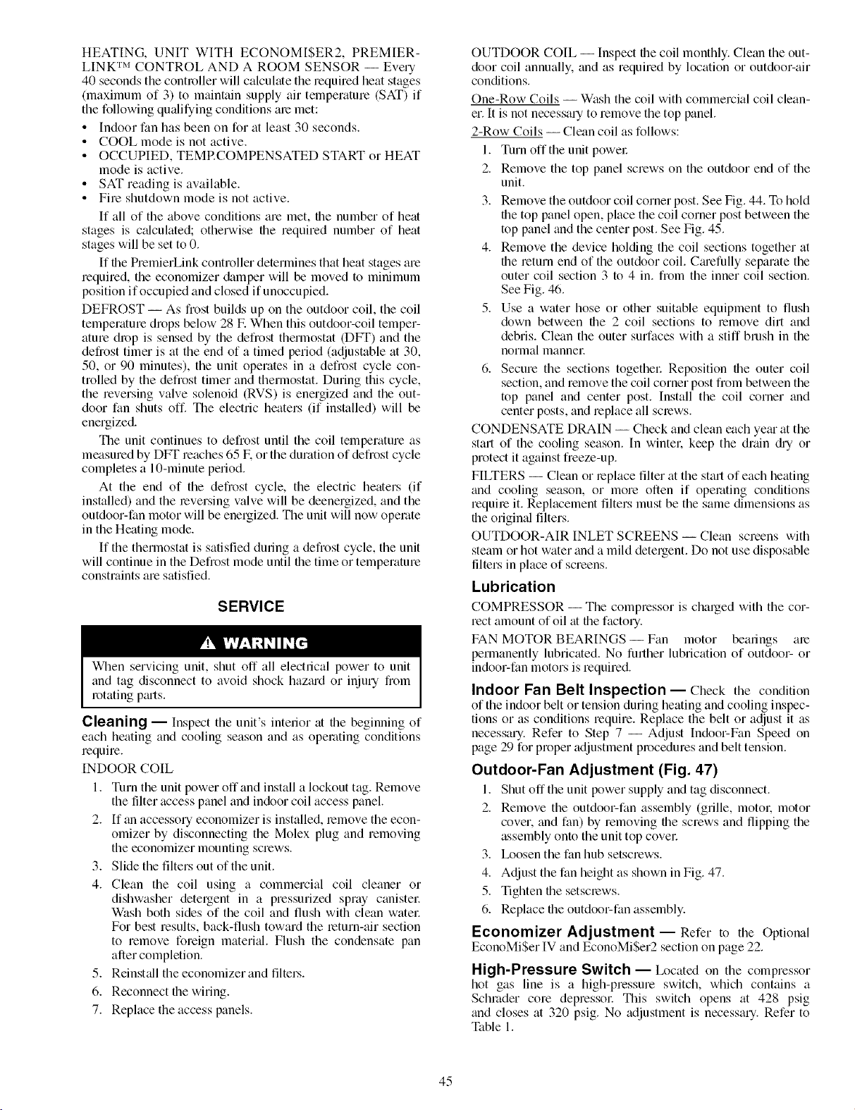
HEATING, UNIT WITH ECONOMI$ER2, PREMIER-
LINK TM CONTROL AND A ROOM SENSOR -- Every
40 seconds the controller will calculate the required heat stages
(maximum of 3) to maintain supply air temperature (SAT) if
the following qualifying conditions ale met:
• Indoor fan has been on for at least 30 seconds.
• COOL mode is not active.
• OCCUPIED, TEMRCOMPENSATED START or HEAT
mode is active.
• SAT reading is available.
• Fire shutdown mode is not active.
If all of the above conditions are met, the number of heat
stages is c_dculated; otherwise file required number of heat
stages will be set to 0.
If the PremierLink controller determines that heat stages are
required, the economizer damper will be moved to minimum
position if occupied and closed if unoccupied.
DEFROST -- As fiost builds up on the outdoor coil, the coil
temperature drops below 28 E When this outdoor-coil temper-
ature drop is sensed by the defrost thermostat (DFT) and the
defrost timer is at the end of a timed period (adjustable at 30,
50, or 90 minutes), the unit operates in a defrost cycle con-
trolled by the defrost timer and thermostat. During this cycle,
the reversing valve solenoid (RVS) is energized and the out-
door fan shuts off. The electric heaters (if installed) will be
energized.
The unit continues to defrost until the coil teraperature as
measured by DFT reaches 65 E or the duration of defrost cycle
completes a 10-minute period.
At the end of the defrost cycle, the electric heaters (if
installed) and the leversing valve will be deenergized, and the
outdoor-fan motor will be energized. The unit will now operate
in the Heating mode.
If the thermostat is satisfied during a defrost cycle, the unit
will continue in the Defrost mode until the time or temperature
constraints are satisfied.
SERVICE
When servicing unit, shut off all electrical power to unit
and tag disconnect to avoid shock hazmd or injury from
rotating p_uts.
Cleaning -- Inspect the unit's interior at the beginning of
each heating and cooling season and as operating conditions
require.
INDOOR COIL
1. Turn the unit power off and install a lockout tag. Remove
the tilter access panel and indoor coil access panel.
2. If an accessory economizer is installed, remove the econ-
omizer by disconnecting the Molex plug and removing
the economizer mounting screws.
3. Slide the filters out of the unit.
4. Clean the coil using a commercial coil cleaner or
dishwasher detergent in a pressurized spray canistel:
Wash both sides of the coil and flush with clean watel:
For best results, back-flush toward the return-air section
to remove foreign materi_fl. Flush the condensate pan
after completion.
5. Reinst_dl the economizer and filters.
6. Reconnect file wiring.
7. Replace the access panels.
OUTDOOR COIL -- Inspect file coil monthly. Clean the out-
door coil annually, and as required by location or outdoor-air
conditions.
One-Row Coils -- Wash the coil with commercial coil clean-
er. It is not necessary to remove the top panel.
2-Row Coils -- Clean coil as follows:
1. Turn off the unit powel:
2. Remove the top panel screws on the outdoor end of the
unit.
3. Remove the outdoor coil corner post. See Fig. 44. To hold
the top panel open, place the coil corner post between the
top panel and the center post. See Fig. 45.
4. Remove the device holding the coil sections together at
file return end of the outdoor coil. Cmefully separate the
outer coil section 3 to 4 in. from the inner coil section.
See Fig. 46.
5. Use a water hose or other suitable equipment to flush
down between the 2 coil sections to remove dirt and
debris. Clean the outer surfaces with a stiff brush in the
normal manneE
6. Secure the sections togethel: Reposifion file outer coil
section, and remove the coil corner post from between the
top panel and center post. Install the coil corner and
center posts, and replace all screws.
CONDENSATE DRAIN -- Check and clean each yem at the
start of the cooling season. In wintel: keep the drain di_ or
protect it against freeze-up.
FILTERS -- Clean or replace filter at the start of each heating
and cooling season, or more often if operating conditions
require it. Replacement filters must be the same dimensions as
file origimd filters.
OUTDOOR-AIR INLET SCREENS -- Clean screens with
steam or hot water and a mild detergent. Do not use disposable
filters in place of screens.
Lubrication
COMPRESSOR -- The compressor is charged with the cor-
rect amount of oil at the factory.
FAN MOTOR BEARINGS-- Fan motor bearings are
permanently lubricated. No further lubrication of outdoor- or
indoor-fan motors is required.
Indoor Fan Belt Inspection -- Check the condition
of the indoor belt or tension during heating and cooling inspec-
tions or as conditions require. Replace the belt or adjust it as
necessary. Refer to Step 7 -- Adjust Indoor-Fan Speed on
page 29 for proper adjustment procedures and belt tension.
Outdoor-Fan Adjustment (Fig. 47)
I. Shut offthe unit power supply and tag disconnect.
2. Remove the outdoor-fan assembly (grille, motol: motor
cover, and fan) by removing file screws and flipping the
assembly onto the unit top covel:
3. Ix)osen the fan hub setscrews.
4. Adjust the fan height as shown in Fig. 47.
5. Tighten file setscrews.
6. Replace file outdoor-fan assembly.
Economizer Adjustment- Refer to the Optional
EconoMi$er IV and EconoMi$er2 section on page 22.
High-Pressure Switch -- Ix)cated on the compressor
hot gas line is a high-pressure switch, which contains a
Schmder core depressoc This switch opens at 428 psig
and closes at 320 psig. No adjustment is necessary. Refer to
Table 1.
45
Page 46
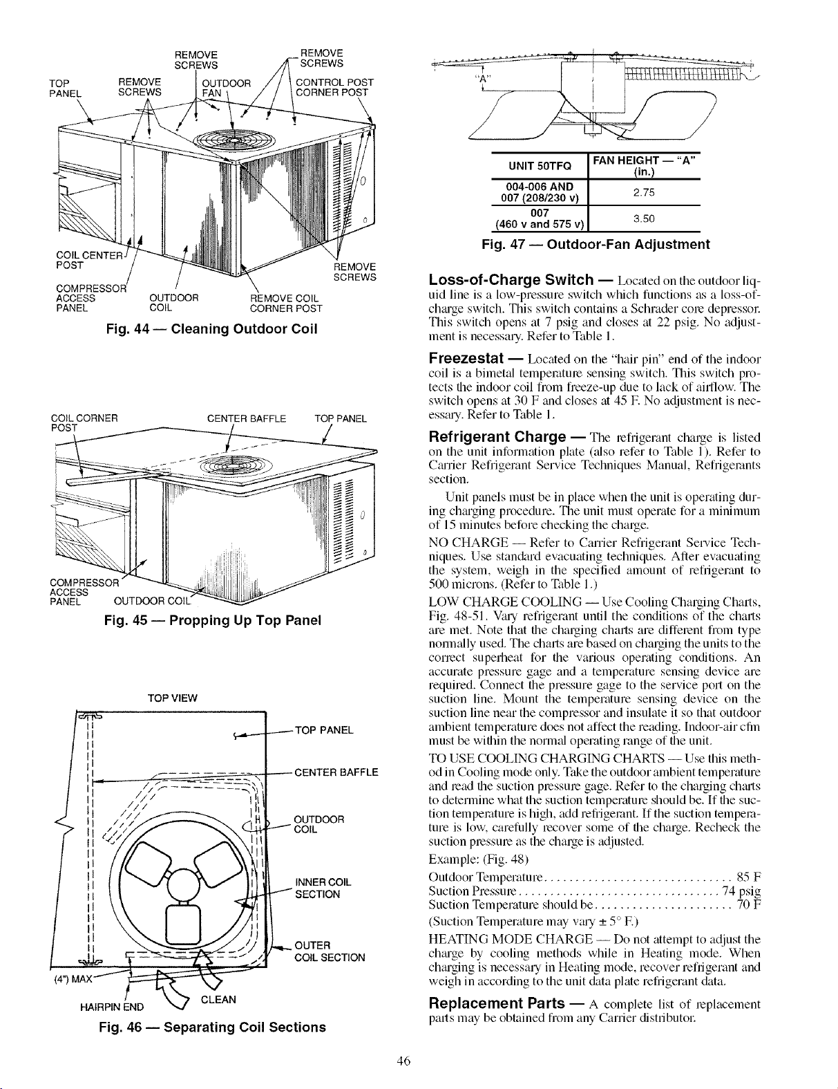
TOP
PANEL
REMOVE
CONTROLPOST
CORNER POST
REMOVE
SCREWS
REMOVE
SCREWS
OUTDOOR
\
COILCENTEF
POST
ACCESS
PANEL
OUTDOOR REMOVE COIL
COIL CORNER POST
Fig. 44-- Cleaning Outdoor Coil
CO[LCORNER
POST
COMPRESSOR
ACCESS
PANEL OUTDOOR CO
Fig. 45 -- Propping Up Top Panel
TOP VIEW
1
1
I
/// t
///
///
(4")
HAIRPIN END
Fig. 46 -- Separating Coil Sections
REMOVE
SCREWS
CENTER BAFFLE TOP PANEL
.-----TOP PANEL
_CENTER BAFFLE
OUTDOOR
INNERCOIL
OUTER
COILSECTION
CLEAN
UNIT50TFQ ] FAN HEIGHT -- "A"
I
(in.)
004-006 AND I
007 (2081230v) ] 2.75
007
(460 v and 575 v) 3.50
Fig. 47 -- Outdoor-Fan Adjustment
Loss-of-Charge Switch -- Ix>cated on the outdoor liq-
uid line is a low-pressure switch which functions as a loss-of-
chmge switch. This switch contains a Schrader cole depressol:
This switch opens at 7 psig and closes at 22 psig. No adjust-
ment is necessary. Refer to Table 1.
Freezestat -- Ix_cated on the "hair pin" end of the indoor
coil is a bimetal temperature sensing switch. This switch pro-
tects file indoor coil from freeze-up due to lack of aidlow. The
switch opens at 30 F and closes at 45 E No adjustment is nec-
esstuy. Refer to Table 1.
Refrigerant Charge -- The refrigerant charge is listed
on the unit information plate (_dso refer to Table 1). Refer to
Cmrier Refi'igerant Service Techniques Manual, Refrigerants
section.
Unit panels must be in place when the unit is operating dur-
ing chguging procedure. The unit must operate for a minimum
of 15 minutes before checking the charge.
NO CHARGE -- Refer to Carrier Refrigerant Service Tech-
niques. Use standard evacuating techniques. After evacuating
the system, weigh in the specified amount of refrigerant to
500 microns. (Refer to Table 1.)
LOW CHARGE COOLING -- Use Cooling Charging Chmls,
Fig. 48-51. Vmy refrigerant until the conditions of the charts
are met. Note that the charging chmls are diffelent from type
normally used. The charts are based on charging the units to the
conect superheat for the various operating conditions. An
accurate pressure gage and a temperature sensing device are
required. Connect the pressure gage to the service poll on the
suction line. Mount the temperature sensing device on the
suction line near the compressor and insulate it so that outdoor
ambient temperature does not affect the reading. [ndoor-air cfln
must be within the normal operating range of the unit.
TO USE COOLING CHARGING CHARTS --Use this meth-
od in Cooling mode only. Take the outdoor ambient temperature
and lead the suction plessme gage. Refer to the charging chmts
to determine what the suction temperatme should be. [f the suc-
tion temperature is high, add refrigerant. If the suction tempera-
ture is low. carefully lecover some of the charge. Recheck the
suction plessme as the charge is adjusted.
Example: (Fig. 48)
Outdoor Temperature .............................. 85 F
Suction Pressme ................................ 74 psig
Suction Temperature should be ...................... 70 F
(Suction Temperature may v_u'y _+5° E)
HEATING MODE CHARGE -- Do not attempt to adjust the
chmge by cooling methods while in Heating mode. When
ch_uging is necessary in Heating mode, recover refrigerant and
weigh in according to the unit &tta plate refrigerant &_ta.
Replacement Parts -- A complete list of leplacement
parts may be obtained from any Carrier distributol:
46
Page 47
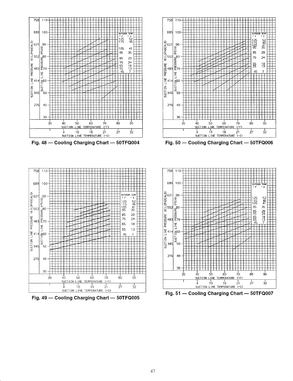
I 111111111111111111111111114
+++ +oo- - - oo+_+_,+,0,
125 52
m _ 105 41+
552 m I I I I_+ I I _ I_+ I t +-4 + + 95 35 l
!_ , +Is +I
i i
_ I IXl I I I_l._ I I I [+--{11 I i 1 75 24
¢_70 -_483 _ J t t I J'l I + I D"t_I I I 1"4" I I I 55 13
z414z60--- II _"' _' +' _'_ I ' +' +_+ I I I I II II-I'''_' ' ' '_-' +' +
z _ I I /I I IJ.+'_l I I I l_llr I i I I VIi I I I I I I I
_34E 50 -
o'_ I I till IIII1111YlIIIIIIItlIIt
-4+ --kHq-H4q_
27B 40- I ltllllltll IIIIIit111111111
Fig. 48 -- Cooling Charging Chart -- 50TFQO04
I IIIitllt111111111111111111
I III lllllll IIIIIIIIIIIIIIII
30-
I I II lllllll llllllllllllllll
3O
I
I I.-t/I I I I I_W'I ! + l.-tfl I I !
I I I I_lft I I I_k'l I I I t.4_-I I
•_1fl I I I_ I I I t_4_11 I J_F I 65 18
50 60 70 80 90
40
SUCTION LINE TEMPERATURE ('F)
1 t I I
4 10 16 21
SUCTION LINE TEMPERATURE ('C)
I I
27 32
30 40 50 60 70
SUCTION LINE TEMPERATURE ('F)
l 4 II0 I£ 211
SUCTION LINE TEMPERATURE ('C)
Fig. 50 -- Cooling Charging Chart -- 50TFQO06
758
689
B21
o
552
483 _70-
4_4 _60
345 5O -
27B 40
40 SO BO 70 BO £0
SUCTION LINE TEMPERATURE OF)
I L I I I l
4 10 15 21 27 32
SUCTION LINE TEMPERATURE (+C)
Fig. 49 -- Cooling Charging Chart -- 50TFCIO05
758 110-
689 100-
621 90 --
g _
uJ
i IIIIIIIIIII 115 4_
......... i 95 35
_2ZZZZ- _ 85 29
...... _ 75 24
0+70 -
_ +_0-
__i-" 'lllL_f_lll'l''illlll li
345 50 -
27B
+- III11111111I ' '+"
- ' I fFH--H--4_
lllllIlllll I I I I
lllllllllll I I I I
lllllllllll I I I I
Iiiiiiiiiii I I I I
iliiiiiiiii I I
IIIIIIIIII I I
IIIIIIIIIII I I
+liI,+,I+l_-_ I
J_'l I/l I I I_-I I
I_I I I 1]_411 1 I d l l II II
l lIF_d'l I l I !_ l; _ IIl l I l
_llllllJ111-ll I/ I fill It
J11_-lllll#l I _III I
_lllll#lll _ IIII I
IIIlL+.4_IIIII "I IIII I
llL-4fllllll I V l I III I
I KIIIIIIlll _! I Illl I
IIIIIIIIIIK I I IIII I
IIIIIIIIIII I I IIII I
lllllllllll I
i I _ I II II
_i-+ + ++-H-H-_
30- IIIIIIil111 I I IIit ÷
30 40 50 60 70 80 90
SUCTION LINE TEMPERATURE ('F)
SUCTION LINE TEMPERATURE ('C)
Fig. 51 -- Cooling Charging Chart -- 50TFCIO07
I I I I I
47
Page 48

TROUBLESHOOTING
Unit Troubleshooting -- For unit troubleshooting, refer
to Fig. 52 and Table 33.
EeonoMiSer IV Troubleshooting -- See Table 34
for EconoMi$er IV logic.
A functional view of the EconoMi$er IV is shown in
Fig. 53. Typic:d settings, sensor ranges, and jumper positions
are also shown. An EconoMi$er IV simulator program is
available fiom CtuTier to help with EconoMi$er W training
and troubleshooting.
ECONOMI$ER IV PREPARATION -- This procedure is
used to prepare the EconoMi$er IV for troubleshooting. No
troubleshooting or testing is done by performing the following
procedme.
NOTE: This procedure requires a 9-v battely, 1.2 kilo-ohm
resistol: and a 5.6 kilo-ohm resistor which are not supplied
with the EconoMi$er IV.
IMPORTANT: Be sure to record the positions of all poten- ]
tiometers before starting troubleshooting.
1. Disconnect power at TR and TRI. All LEDs should be
off. Exhaust fan contacts should be open.
2. Disconnect device at P and Pl.
3. Jumper Pto Pl.
4. Disconnect wires at T and TI. Place 5.6 kilo-ohm resistor
across T and TI.
5. Jumper TR to 1.
6. Jumper TR to N.
7. If connected, remove sensor from terminals S o and +.
Connect 1.2 kilo-ohm 4074EJM checkout resistor across
terminals SO and +.
8. Put 620-ohm resistor across terminals SR and +.
9. Set minimum position, DCV set point, and exhaust
potentiometers fully CCW (counterclockwise).
10. Set DCV maximum position potentiometer fully CW
(clockwise).
11. Set enthalpy potentiometer to D.
12. Apply power (24 vac) to terminals TR and TRI.
DIFFERENTIAL ENTHALPY-- To check differential
enthalpy:
1. Make sure EconoMiSer IV preparation procedure has
been performed.
2. Place 620-ohm resistor across SO and +.
3. Place 1.2 kilo-ohm resistor across SR and +. The Free
Cool LED should be lit.
4. Remove 620-ohm resistor across S O and +. The Free
Cool LED should turn off.
5. Return EconoMiSer IV settings and wiring to normal
after completing troubleshooting.
SINGLE ENTHALPY -- To check single enthalpy:
1. Make sure EconoMiSer IV preparation procedure has
been performed.
2. Set the enthalpy potentiometer to A (fully CCW). The
Free Cool LED should be lit.
3. Set the enth_dpy potentiometer to D (fully CW). The Free
Cool LED should turn off.
4. Return EconoMiSer IV settings and wiring to normal
after completing troubleshooting.
DCV (Demand Controlled Ventilation) AND POWER
EXHAUST -- To check DCV and Power Exhaust:
1. Make sure EconoMiSer IV preparation procedure has
been performed.
2. Ensure terminals AQ and AQI _ue open. The LED for
both DCV and Exhaust should be off. The actuator
should be lully closed.
1
3. Connect a 9-v battery to AQ (positive node) and AQl
(negative node). The LED for both DCV and Exhaust
should turn on. The actuator should drive to between 90
and 95% open.
4. Turn the Exhaust potentiometer CW until the Exhaust
LED turns off. The LED should turn off when the poten-
tiometer is approximately 90%. The actuator should
remain in position.
5. Turn the DCV set point potentiometer CW until the DCV
LED turns off. The DCV LED should turn off when the
potentiometer is approximately 9 v. The actuator should
drive fully closed.
6. Turn the DCV and Exhaust potentiometers CCW until
the Exhaust LED turns on. The exhaust contacts will
close 30 to 120 seconds after the Exhaust LED turns on.
7. Return EconoMiSer IV settings and wiring to norm_d
after completing troubleshooting.
DCV MINIMUM AND MAXIMUM POSITION -- To check
the DCV minimum and maximum position:
1. Make sure EconoMiSer IV plepmation procedure has
been perforlned.
2. Connect a 9-v battery to AQ (positive node) and AQI
(negative node). The DCV LED should turn on. The
actuator should drive to between 90 and 95% open.
3. Turn the DCV Maximum Position potentiometer to mid-
point. The actuator should drive to between 20 and 80%
open.
4. Turn the DCV Maximum Position potentiometer to lully
CCW. The actuator should drive fully closed.
5. Turn the Minimum Position potentiometer to midpoint.
The actuator should drive to between 20 and 80% open.
6. Turn the Minimum Position Potentiometer lhlly CW. The
actuator should drive fully open.
7. Remove the jumper from TR and N. The actuator should
drive fully closed.
8. Return EconoMiSer IV settings and wiring to norm_d
after completing troubleshooting.
SUPPLY-AIR INPUT -- To check supply-air input:
1. Make sure EconoMiSer IV plepmation procedure has
been performed.
2. Set the Enthalpy potentiometer to A. The Free Cool LED
turns on. The actuator should drive to between 20 and
80% open.
3. Remove the 5.6 kilo-ohm lesistor and jumper T to TI.
The actuator should drive lully open.
4. Remove the jumper across T and TI. The actuator should
drive fully closed.
5. Return EconoMiSer IV settings and wiring to norm_d
after completing troubleshooting.
ECONOMISER IV TROUBLESHOOTING COMPLE-
TION -- This procedure is used to return the EconoMi$er IV
to operation. No troubleshooting or testing is done by perform-
ing the following procedure.
1. Disconnect power at TR and TRI.
2. Set enthalpy potentiometer to previous setting.
3. Set DCV maximum position potentiometer to previous
setting.
4. Set minimum position, DCV set point, and exhaust
potentiometers to previous settings.
5. Remove 620-ohm resistor fi_)m terminals SR and +.
6. Remove 1.2 kilo-ohm checkout resistor from terminals SO
and +. If used, reconnect sensor fi_)m terminals So and +.
7. Remove jumper from TR to N.
8. Remove jumper from TR to 1.
9. Remove 5.6 kilo-ohm resistor fiom T and TI. Reconnect
wiles at T and TI.
10. Remove jumper from P to PI. Reconnect device at P and PI.
11. Apply power (24 vac) to termimds TR and TRI.
48
Page 49

I
DEFROST
BOARB TRAN
ITB4
ITB4
°
COMPONENTARRANGEMENT
C -- Contactor, Compressor
CAP -- Capacitor
CH -- Crankcase Heater
COMP -- Compressor Motor
DB -- Defrost Board
EQUIP- Equipment
FPT -- Freeze-Up Protection
FU -- Fuse
GND -- Ground
HPS -- High-Pressure Switch
HR -- Heater Relay
IFC -- Indoor Fan Contactor
IFM -- Indoor-Fan Motor
LPS -- Low-Pressure Switch
LSM -- Limit Switch (Motor)
OFM -- Outdoor-Fan Motor
OLR -- Overload Relay
P -- Plug
PL -- Plug Assembly
QT -- Quadruple Terminal
RVS -- Reversing Valve Solenoid
SAT -- Supply Air Thermostat
TRAN -- Transformer
Thermostat
LEGEND
Field Splice
Marked Wire
Terminal (Marked)
42f>
o
Terminal (Unmarked)
CZB
-- Factory Wiring
.... Field Control Wiring
I /
i
Terminal Block
Splice
Splice (Marked)
Field Power Wiring
Accessory or Optional Wiring
To indicate common potential only,
not to represent wiring
Fig. 52 -- Typical Wiring Schematic
°uq
NOTES:
1. If any of the original wire furnished must be
2. Three phase motors are protected under primary
3. Use copper conductors only.
4. Use copper, copper-clad aluminum or aluminum
5.
6. Unit will have either LSM or OLR, but not both.
49
replaced, it must be replaced with type 90 C wire or
its equivalent.
single phasing conditions.
conductors.
VOLTAGE CB MUST TRIP
RATING MFG, PT, NO. AMPS
24V W2BX-1024-3.2
POTTER & BRUMFIELD 3.2
Page 50
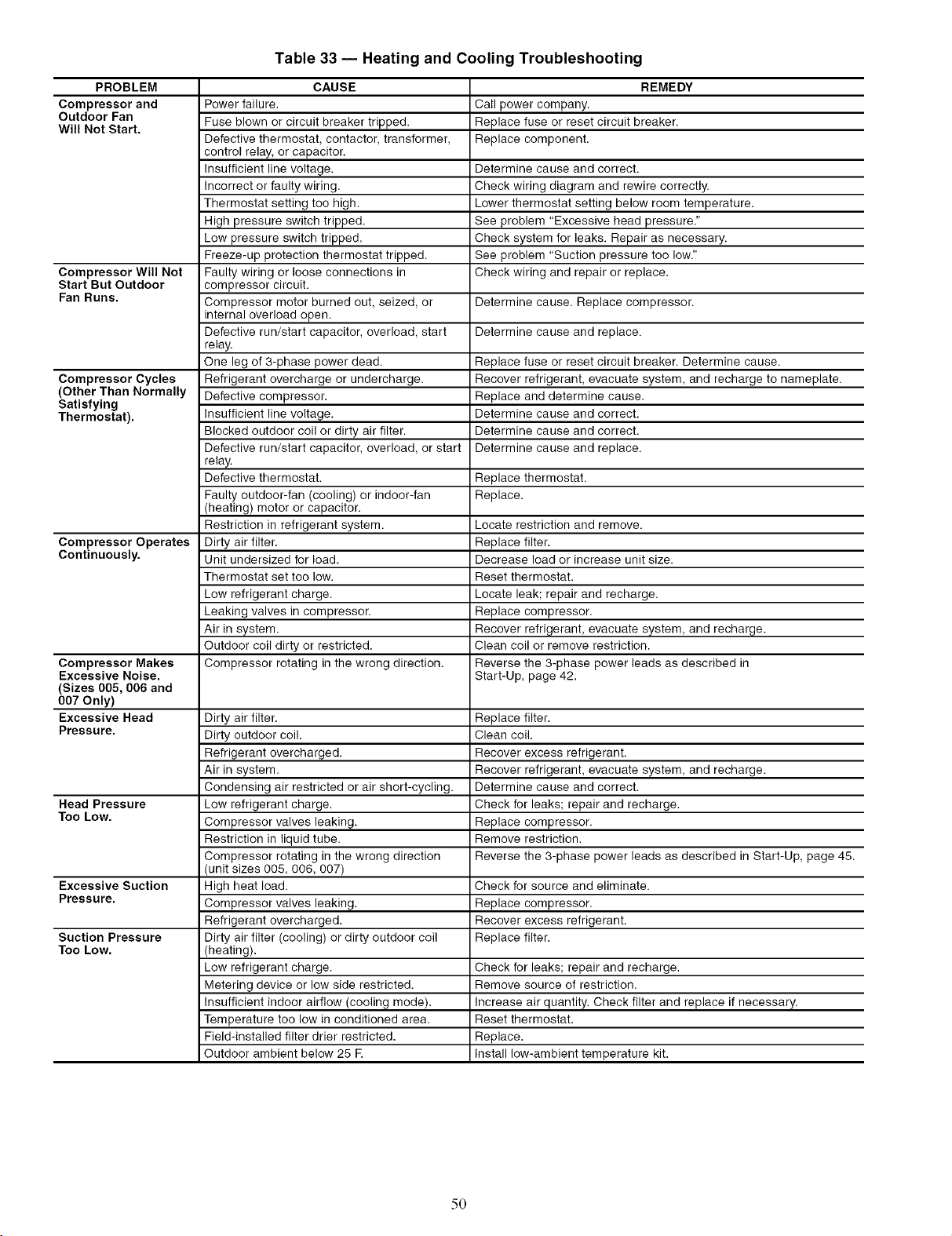
Table 33 -- Heating and Cooling Troubleshooting
PROBLEM CAUSE REMEDY
Compressor and Power failure. Call power company.
Outdoor Fan Fuse blown or circuit breaker tripped. Replace fuse or reset circuit breaker.
Will Not Start.
Compressor Will Not Faulty wiring or loose connections in Check wiring and repair or replace.
Start But Outdoor compressor circuit.
Fan Runs. Compressor motor burned out, seized, or Determine cause. Replace compressor.
Compressor Cycles Refrigerant overcharge or undercharge. Recover refrigerant, evacuate system, and recharge to nameplate.
(Other Than Normally Defective compressor. Replace and determine cause.
Satisfying
Thermostat). Insufficient line voltage. Determine cause and correct.
Compressor Operates Dirty air filter. Replace filter.
Continuously. Unit undersized for load. Decrease load or increase unit size.
Compressor Makes Compressor rotating in the wrong direction. Reverse the 3-phase power leads as described in
Excessive Noise. Start-Up, page 42.
(Sizes 005, 006 and
007 Only)
Excessive Head
Pressure.
Head Pressure
Too Low.
Excessive Suction
Pressure.
Suction Pressure
Too Low.
Defective thermostat, contactor, transformer, Replace component.
control relay, or capacitor.
Insufficient line voltage. Determine cause and correct.
Incorrect or faulty wiring. Check wiring diagram and rewire correctly.
Thermostat setting too high. Lower thermostat setting below room temperature.
High pressure switch tripped. See problem "Excessive head pressure."
Low pressure switch tripped. Check system for leaks. Repair as necessary.
Freeze-up protection thermostat tripped. See problem "Suction pressure too low."
internal overload open.
Defective run/start capacitor, overload, start Determine cause and replace.
relay.
One leg of 3-phase power dead. Replace fuse or reset circuit breaker. Determine cause.
Blocked outdoor coil or dirty air filter. Determine cause and correct.
Defective run/start capacitor, overload, or start Determine cause and replace.
relay.
Defective thermostat. Replace thermostat.
Faulty outdoor-fan (cooling) or indoor-fan Replace.
(heating) motor or capacitor.
Restriction in refrigerant system. Locate restriction and remove.
Thermostat set too low. Reset thermostat.
Low refrigerant charge. Locate leak; repair and recharge.
Leaking valves in compressor. Replace compressor.
Air in system. Recover refrigerant, evacuate system, and recharge.
Outdoor coil dirty or restricted. Clean coil or remove restriction.
Dirty air filter.
Dirty outdoor coil.
Refrigerant overcharged.
Air in system.
Condensing air restricted or air short-cycling.
Low refrigerant charge.
Compressor valves leaking.
Restriction in liquid tube.
Compressor rotating in the wrong direction
[unit sizes 005, 006, 007)
High heat load.
Compressor valves leaking.
Refrigerant overcharged.
Dirty air filter (cooling) or dirty outdoor coil
(heating).
Low refrigerant charge.
Metering device or low side restricted.
Insufficient indoor airflow (cooling mode).
Temperature too low in conditioned area.
Field-installed filter drier restricted.
Outdoor ambient below 25 E
Replace filter.
Clean coil.
Recover excess refrigerant.
Recover refrigerant, evacuate system, and recharge.
Determine cause and correct.
Check for leaks; repair and recharge.
Replace compressor.
Remove restriction.
Reverse the 3-phase power leads as described in Start-Up, page 45.
Check for source and eliminate.
Replace compressor.
Recover excess refrigerant.
Replace filter.
Check for leaks; repair and recharge.
Remove source of restriction.
Increase air quantity. Check filter and replace if necessary.
Reset thermostat.
Replace.
Install low-ambient temperature kit.
5O
Page 51

Table 34 -- EconoMi$er IV Input/Output Logic
INPUTS
Demand Control
Ventilation (DCV)
Below set
(DCV LED Off)
Above set
(DCV LED On)
*For single enthalpy
enthalpy to the ABCD
1-Power at N terminal determines Occupied/Unoccupied
24 vac (Occupied), no power (Unoccupied).
**Modulation is based on the supply-air sensor signal.
ttModulation is based on the DCV signal.
High Low On On On On
(Free Cooling LED Off) On Off On Off
Low High On On On Off
(Free Cooling LED On) On Off Off Off
High Low On On On On
(Free Cooling LED Off) On Off On Off
Low High On On On Off
(Free Cooling LED On) On Off Off Off
control, the module compares outdoor
set point.
Enthalpy* Compressor
Outdoor Return Y1 Y2 Stage Stage
1 2
Off Off Off Off
Off Off Off Off
Off Off Off Off
Off Off Off Off
***Modulation is based on the greater of DCV and supply-air sen-
setting:
tttModulation is based on the greater of DCV and mixed air sensor
OUTPUTS
N Terminalt
Occupied Unoccupied
Damper
Minimum position Closed
Modulating** (between min.
3osition and full-open)
Minimum position
Modulatingl-t (between min.
3osition and DCV maximum)
Modulating***
sor signals, between minimum position and either maximum
position (DCV) or fully open (supply-air signal).
signals, between closed and either maximum position (DCV) or
fully open (supply-air signal).
Modulating** (between
closed and full-open)
Closed
Modulatingtl- (between
closed and DCV
maximum)
Modulatingl-l-t
Fig. 53 -- EconoMi$er IV Functional View
51
Page 52

INDEX
Access panels 23
Barometric flow capacity 25
Carrier Comfort Network 18
ChaNing chart, refrigerant 47
Clearance 2, 6
CO2 sensor
Configuration 28
Settings 2Z 29
Compressor
Lubrication 45
Mounting 42
Rotation 42
Condensate drain
Cleaning 45
Location 2,4
Control circuit
Wiring 16
Wiring raceway 16
Convenience outlet 13-1.5,17
Defrost board 16
Demand ventilation control 28
Dehumidification 28
Dimensions 3, 6
Ductwork 2
EconoMiSer2 22-24
4 to 20 mA control 24
Components 22
Wiring 24
EconoMi$er IV 22-28
Components 22
Control mode 25
Damper 28
Dry bulb changeover 25
Enthalpy changeover 26
Inputs and outputs 51
Troubleshooting 48
Wiring 24
Electrical connections 7
Electrical data 10-15
Electric heat 9
Enthalpy changeover set points 27
Factory-installed options
Convenience outlet 17
Disconnect switch 17
EconoMi$er2 22
EconoMiSer IV 22-28
Manual outdoor air damper 17,18
Novar controls 17
PremierLink TM controls 18-20
Filter
Cleaning 45
Installation 23
Size 5
Freeze protection thermostat .5,46
Heat anticipator settings 16
High flow valves 42
High pressure switch 5, 45
Horizontalunits 1,2
Ilndoor air quality sensor l& 26
Indoor coil 5
Cleaning 45
Indoor fan motor .5,29-41
Lubrication 57
Motor data 30
Performance 31-41
Pulley adjustment 29
Pulley setting .5,30
Speed 5
Low pressure switch .5,46
Manual outdoor air damper IZ 18
Mounting
Compressor 42
Unit 2
Novar controls 17
Operating sequence
Cooling 43
Defrost 45
EconoMi$er2 43-45
EconoMi$er IV 43
Heating 43
Outdoor air hood 1Z 23
Outdoor air inlet screens
Cleaning 45
Ontdoor air temperature sensor 18,22
Outdoor coil 5
Cleaning 45
Outdoor fan 5
Adjustment 4.5,46
Physical data 5
Power supply
Wiring 7,8
PremierLink controls 16,18-20
Pressure, drop
Economizer 30
Pressure switches
High pressure .5,45
Low pressure 5, 46
Pre-Start-Up 42
Refrigerant
Charge .5,46
Type 5
Refrigerant service ports 42
Replacement parts 46
Return air filter 5, 42
Return air temperature sensor 26
Rigging unit 2, 4
Roof curb
Assembly 1
Dimensions 3
Connector package 3
Leveling tolerances 4
Weight 5
Safety considerations 1
Safety relief 43
SelMce 45-47
Selwice ports 42
Slab mount 2
Start-up 42-45
Start-up checklist CL-1
Supply-air temperature sensor 18,22
Thermostat 16
Troubleshooting 48-51
Ventilation 43
Weight
Corner 6
EconoMi$er IV .5,6
Unit 4-6
Wiring
4 to 20 mA control 24
Differential enthalpy 21
EconoMi$er2 24
EconoMiSer IV 24
Power connections 8
PremierLink 20
Thermostat 16
Unit 49
52
Page 53

Copyright 2005 Carrier Corporation
Manufacturer reserves the right to discontinue, or change at any time, specifications or designs without notice and without incurring obligations.
Catalog No. 04-53500018-01 Printed in U.S.A. Form 50TFQ-8SI Pg 54 9-05 Replaces: 50TFQ-6SI
Page 54

START-UP CHECKLIST
(Remove and Store in Job File)
PRELIMINARY INFORMATION
MODEL NO.:
DATE:
BUILDING NAME:
SERIAL NO.:
TECHNICIAN:
BUILDING LOCATION:
II. PRE-START-UP (insert checkmark in box as each item is completed)
[] VERIFY THAT CONDENSATE CONNECTION IS INSTALLED PER INSTALLATION INSTRUCTIONS
[] CHECK ALL ELECTRICAL CONNECTIONS AND TERMINALS FOR TIGHTNESS
[] CHECK THAT INDOOR AIR FILTER ARE CLEAN AND IN PLACE
[] VERIFY THAT UNIT INSTALLATION IS LEVEL
[] CHECK FAN WHEEL AND PROPELLER FOR LOCATION IN HOUSING/ORIFICE AND SETSCREW
TIGHTNESS
[] CHECK PULLEY ALIGNMENT AND BELT TENSION REFER INSTALLATION INSTRUCTIONS
(Size 007 Standard Motor and Sizes 004-006 Alternate Motor and Drives)
[] CHECK THAT NO ELECTRICAL WIRES ARE IN CONTACT WITH REFRIGERANT TUBING OR SHARP EDGES.
[] VERIFY INSTALLATION OF ECONOMIZER HOOD (IF EQUIPPED)
III. START-UP:
ELECTRICAL
SUPPLY VOLTAGE LI-L2 L2-L3 L3-LI
COMPRESSOR AMPS LI L2 L3
INDOOR-FAN AMPS LI L2 L3
LU
z
m
£3
LU
C3
Z
o,
<
(o
TEMPERATURES AND PRESSURES
OUTDOOR-AIR TEMPERATURE DB
RETURN-AIR TEMPERATURE DB
COOLING SUPPLY AIR DB
WB
WB
WB
REFRIGERANT SUCTION PSIG
SUCTION LINE TEMPERATURE F
REFRIGERANT DISCHARGE PSIG
LIQUID LINE TEMPERATURE F
[] VERIFY THAT 3-PHASE SCROLL COMPRESSOR IS ROTATING IN THE CORRECT DIRECTION
[] VERIFY REFRIGERANT CHARGE USING COOLING CHARGING CHARTS ON PAGE 47 (COOLING MODE ONLY).
UNIT MUST OPERATE A MINIMUM OF 15 MINUTES BEFORE ADJUSTING CHARGE.
GENERAL
[] SET ECONOMIZER MINIMUM VENT AND CHANGEOVER SETFINGS TO MATCH JOB REQUIREMENTS
(IF EQUIPPED)
LU
z
m
C3
LU
C3
Z
o,
<
(o
Copyright 2005 Carrier Corporation
Manufacturer reserves the right to discontinue, or change at any time, specifications or designs without notice and without incurring obligations.
Catalog No, 04-53500018-01 Printed in U.SA. Form 50TFQ-8SI Pg CL-1 9-05 Replaces: 50TFQ-6SI
 Loading...