

Page 1
Product
Data
50TFF007-014
Single-Package Rooftop Units
Electric Cooling
with Electric Heat Option
50 Hz
Nominal Capacity: 17.6 kW to 35.9 kW
(5 to 10.2 Tons)
Single-Package Rooftop Units with:
• Galvanized pre-painted steel
cabinet
• Fifty-one mm (2-in.) return-air filters
• Commercial strength base rails
• Exclusive tool-less filter access
panel
• Corrosion-resistant sloped
condensate pan
• Single power entry to unit
• Commercial duty motors with
permanently lubricated bearings
• Standard cooling operation at
outdoor ambient temperatures as
low as –4 C (25 F)
• Meets ASHRAE Standard 62
(Indoor Air Quality)
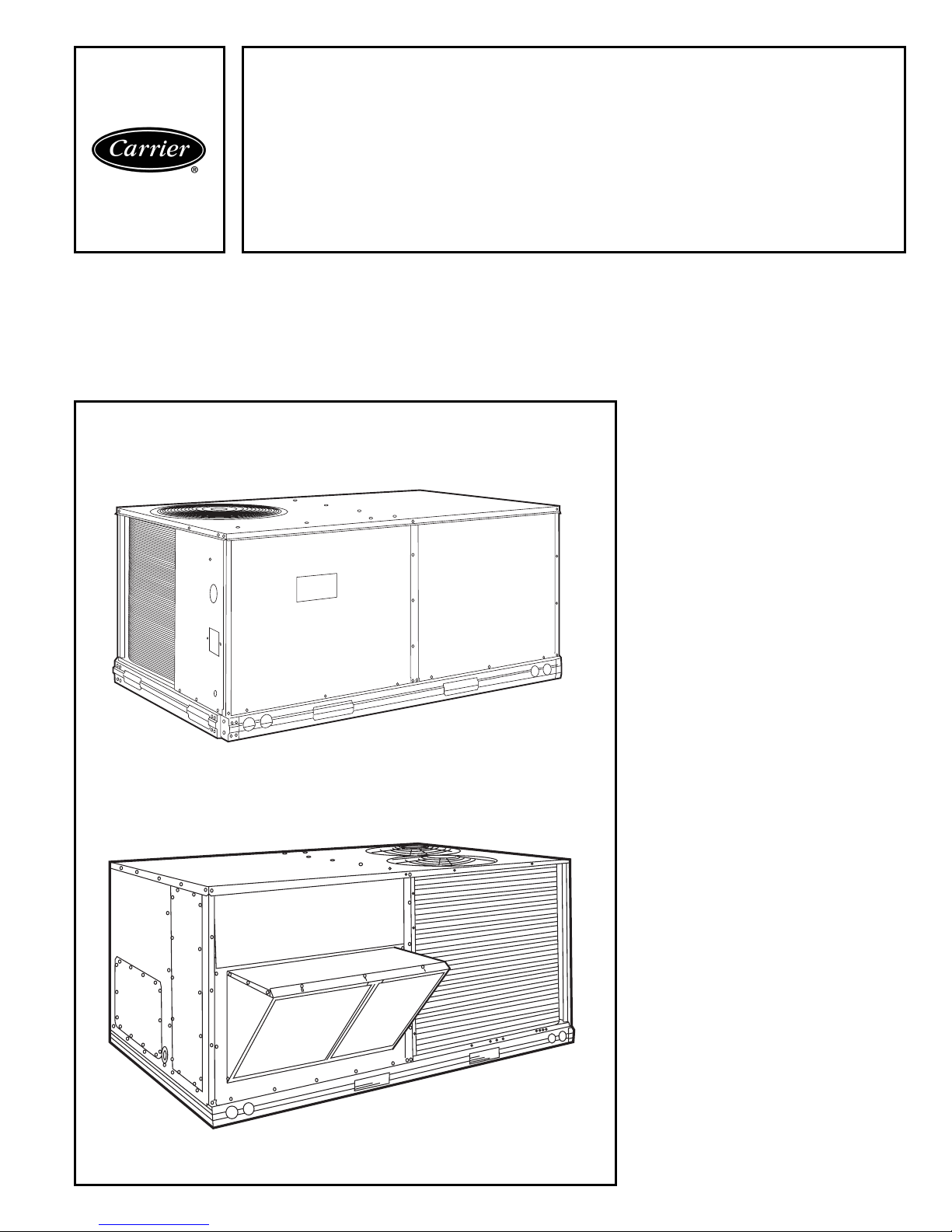
50TFF007
50TFF008-014
Features/Benefits
Compact, vertical discharge
units convert to horizontal
discharge, combining
installation flexibility with
efficient performance and
easy maintenance.
Easy installation and
conversion
All units are shipped in the vertical discharge configuration for fit-up to
standard roof curbs. (Two different curb
sizes fit unit sizes 007 and 008-014.)
The contractor can order and install the
roof curb early in the construction
stage, before decisions on size requirements are made.
All units feature roll-formed baserail
design with forklift slots on 3 sides and
rigging holes for easier maneuvering.
Durable packaging protects all units
during shipment and storage.
The units can be easily converted
from a vertical to a horizontal
discharge configuration by interchanging the panels supplied with the unit.
Copyright 2000 Carrier Corporation Form 50TFF-C1PD
Page 2

All units feature a non-corrosive
sloped condensate drain pan in accordance with ASHRAE (American Society of Heating, Refrigeration and Air
Conditioning Engineers) Standard 62.
Also, the sloped condensate pan on
units permits either an external side
condensate drain (outside the roof curb)
or an internal bottom drain (inside the
roof curb). Both options require fieldsupplied P-trap.
In addition, the 50TFF units have a
standard filter access door, which permits tool-less filter changes.
Field-installed electric heaters are
available in a wide range of capacities.
Single point wiring kit makes installation simple.
Simple electrical connections
Terminal boards, located in the base
unit control box, facilitate connections
to room thermostat, outdoor thermostat(s), economizer, and electric heat.
Service panels are quickly removed,
permitting easy servicing.
Thru-the-bottom service connection
capability and thru-the-curb service
connections accessory allows power
and control wiring to be routed through
the unit basepan or curb, minimizing
roof penetrations. Both power and
control connections are made on the
same side of the unit to simplify installation. In addition, color-coded wires
permit easy tracing and diagnostics.
Proven compressor reliability
Design techniques feature computerprogrammed balance between compressor, condenser, and evaporator.
Carrier-specified hermetic compressors are equipped with compressor
overcurrent and overtemperature protection to ensure dependability.
The 50TFF units have Carrier’s exclusive Acutrol™ metering device which
precisely controls refrigerant flow,
preventing slugging and flood-back,
while maintaining optimum unit
performance.
Carrier’s exclusive Acutrol metering
device precisely controls refrigerant
flow, preventing slugging and floodback, while maintaining optimum unit
performance.
Durable, dependable
construction
Designed for durability in any climate,
the weather-resistant cabinets are
manufactured using pre-painted steel.
The cabinet is constructed of galvanized steel and bonderized, and all exterior panels are coated with a prepainted baked enamel finish. The paint
finish is non-chalking, and is capable of
withstanding Federal (U.S.A.) Test
Method Standard ASTM B117
500-hour salt spray test. All internal
cabinet panels are primed, permitting
longer life and a more attractive appearance for the entire unit. In addition, the 50TFF units are designed with
a single, continuous top piece to eliminate any possible leaks. Totally enclosed condenser-fan motors and permanently lubricated bearings provide
additional unit dependability.
Integrated economizers and
outdoor air
During a first stage call for cooling, if
the outdoor-air temperature is below
the control set point, the supply-air
sensor modulates the economizer outdoor-air damper open to achieve the
set point. When second-stage cooling is
called for, the compressor is energized
in addition to the economizer. If the
outdoor-air temperature is above the
set point, the first stage of compression
is activated and the economizer stays at
minimum vent position. Economizer
operation is controlled by Accusensor™
I dry-bulb thermostat that senses
outdoor-air temperature. Accessory upgrade kits include solid-state enthalpy
control and differential enthalpy sensor.
The Durablade economizer has a reliable sliding plate damper which is easily adjusted for 100% outdoor air,
100% return air, or any proportions of
mixed air.
The 50TFF units also utilize the optional field or factory-installed
EconoMi$er. This newly designed
EconoMi$er incorporates a
parallel-opposed blade design. In
addition, the EconoMi$er has a spring
return built into the damper motor to
provide reliable close-on-power-loss.
The EconoMi$er comes equipped with
up to 100% barometric relief capability
for high outdoor airflow applications.
In addition, the EconoMi$er barometric relief damper or integrated power exhaust accessory can be utilized to
help maintain proper building pressure.
Quiet, efficient operation and
dependable performance
Compressors have vibration isolators
for extremely quiet operation. Efficient
fan and motor design permits operation at very low sound levels, and all
008-014 units are mounted on a special polycore plate.
The 50TFF008-014 units offer high
energy efficiency and lower utility costs
through part load operation using
2 stages of cooling.
Quiet and efficient operation is
provided by belt-driven evaporator fans
(standard). The belt-driven evaporatorfan motor allows adjustment to available static pressure to meet the job requirements of even the most demanding applications.
Increased operating efficiency is
achieved through computer-designed
coils featuring staggered copper tubes.
Fins are ripple-edged for strength,
lanced, and double waved for higher
heat transfer.
Carrier Apollo controls add
reliability, efficiency, and
simplification
The direct digital controls are ordered
as a factory-installed option. Designed
and manufactured exclusively by
Carrier, the controls can be used to actively monitor and control all modes of
operation, as well as to monitor
evaporator-fan status, filter status
indoor-air quality (humidity and carbon
dioxide), supply-air temperature, and
outdoor-air temperature.
Table of contents
Page
Features/Benefits . . . . . . . . . . . . . . . . . . . . . . . . . . . . . . . . . . . . . . . . . 1-3
Model Number Nomenclature . . . . . . . . . . . . . . . . . . . . . . . . . . . . . . . . . . 3
Physical Data . . . . . . . . . . . . . . . . . . . . . . . . . . . . . . . . . . . . . . . . . . . . 4,5
Options and Accessories. . . . . . . . . . . . . . . . . . . . . . . . . . . . . . . . . . . . . 6-8
Base Unit Dimensions . . . . . . . . . . . . . . . . . . . . . . . . . . . . . . . . . . . . . 9,10
Accessory Dimensions . . . . . . . . . . . . . . . . . . . . . . . . . . . . . . . . . . . . 11,12
Selection Procedure . . . . . . . . . . . . . . . . . . . . . . . . . . . . . . . . . . . . . . 13,14
Performance Data . . . . . . . . . . . . . . . . . . . . . . . . . . . . . . . . . . . . . . . 15-33
Electrical Data . . . . . . . . . . . . . . . . . . . . . . . . . . . . . . . . . . . . . . . . . . . . .34
Typical Piping and Wiring . . . . . . . . . . . . . . . . . . . . . . . . . . . . . . . . . . . .35
Typical Wiring Schematic . . . . . . . . . . . . . . . . . . . . . . . . . . . . . . . . . . 36,37
Controls . . . . . . . . . . . . . . . . . . . . . . . . . . . . . . . . . . . . . . . . . . . . . . 38-40
Application Data . . . . . . . . . . . . . . . . . . . . . . . . . . . . . . . . . . . . . . . . . . .41
Guide Specifications. . . . . . . . . . . . . . . . . . . . . . . . . . . . . . . . . . . . . . 42-44
2
Page 3
Features/Benefits (cont)
The Apollo communicating control is
factory-installed into the rooftop unit
evaporator-fan section (007) or unit
control box (008-014), and comes
equipped with built-in diagnostic capabilities. Light-emitting diodes (LEDs)
simplify troubleshooting by indicating
thermostat commands for both stages
of heating and cooling, evaporator-fan
operation, and economizer operation.
The Apollo communicating control is
designed to work specifically with the
Carrier TEMP and VVT® (variable vol-
ume and temperature) thermostats.
The Apollo control combined with
Carrier thermostats incorporate a
5-minute recycle delay timer between
modes of operation to prevent short
cycling.
The standard rooftop control system
is readily adaptable to all conventional
and programmable thermostats. In addition, units with Apollo controls are
suitable for integration into building
monitor control systems if required.
This system gives the 50TFF units the
flexibility to communicate with almost
any thermostat or building control
system.
Indoor-air quality begins with
Carrier rooftops
Sloped condensate pans minimize biological growth in rooftop units in accordance with ASHRAE Standard 62.
Standard 51 mm (2-in.) filters with
optional dirty filter indicator switch provide for greater particle reduction in the
Model number nomenclature
return air. The face-split evaporator
coils improve the dehumidification capability of the standard units, and
standard enthalpy controls provided
with the optional or accessory economizers maximize building humidity
control. The 50TFF units also have an
accessory, 100% open, two-position
damper to meet all your fresh outdoor
air requirements.
For units without economizer, yearround ventilation is enhanced by a
manual outdoor-air damper (ordered as
an accessory or an option on 50TFF
units). The damper can be preset to admit up to 50% outdoor air.
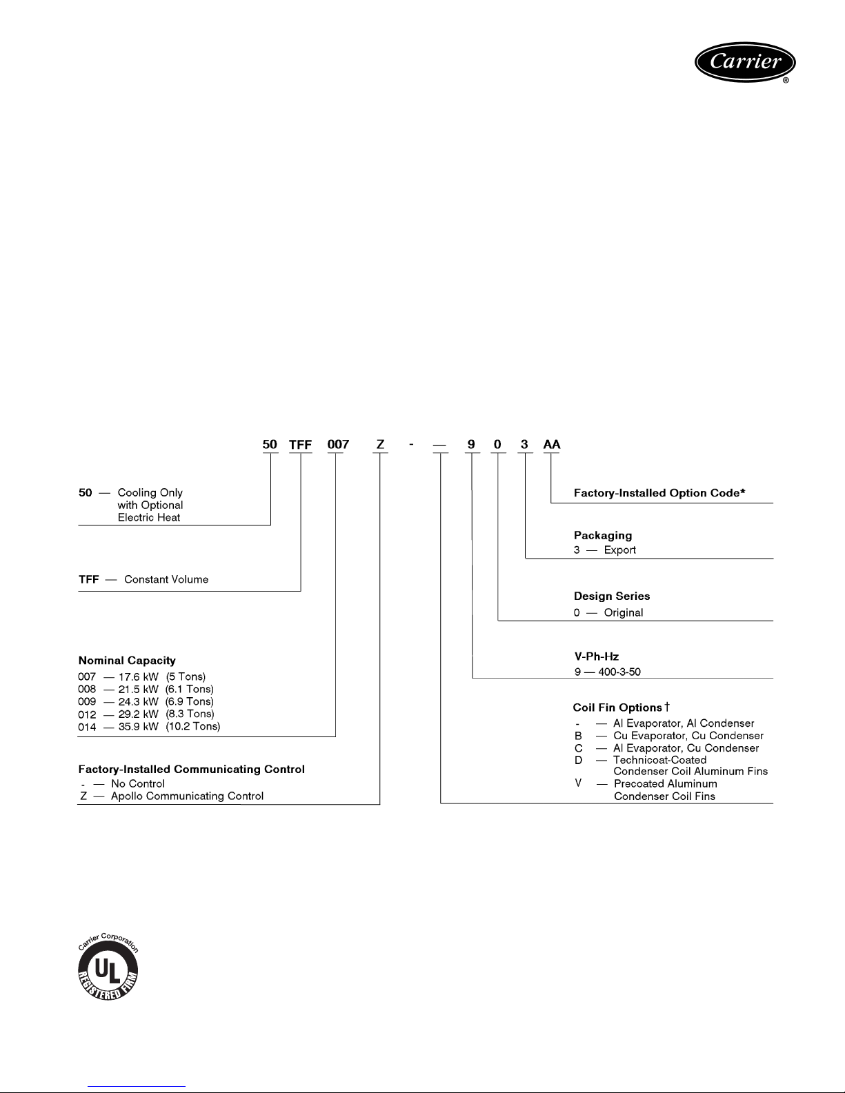
LEGEND
Al — Aluminum
Cu — Copper
FIOP — Factory-Installed Option
Quality Assurance
®
I
S
O
9
0
0
1
:
2
5
2
3
2
A
#
0
0
0
*Refer to 50TFF ordering data or contact your local Carrier representa-
tive for 50TFF FIOP code table.
†All coils have copper tubes.
3
Page 4
Physical data (SI)
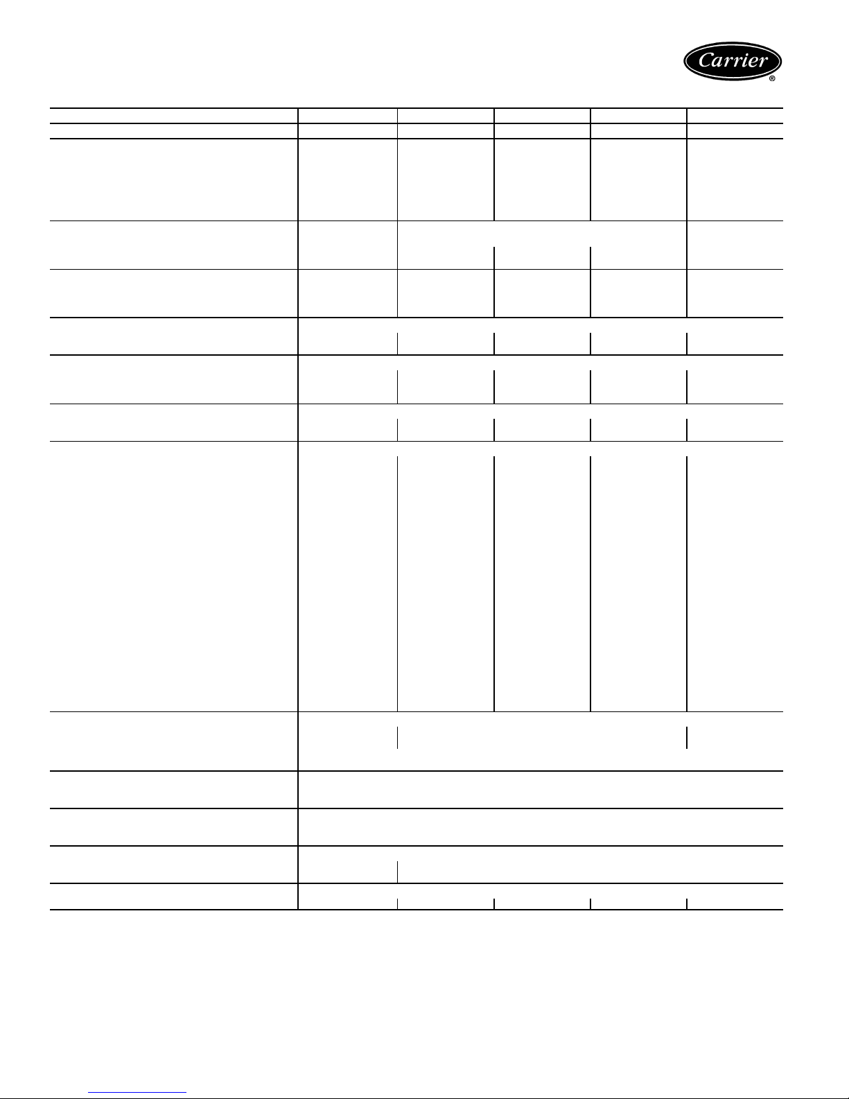
50TFF007-014 UNITS
UNIT SIZE 50TFF 007 008 009 012 014
NOMINAL CAPACITY (kW) 17.6 21.5 24.3 29.2 35.9
OPERATING WEIGHT (kg)
Unit
Al/Al* 213 342 345 415 422
Al/Cu* 245 374 376 447 454
Durablade Economizer 15.4 20.0 20.0 20.0 20.0
EconoMi$er 21 28 28 28 28
Roof Curb† 52 65 65 65 65
COMPRESSOR
Type Scroll Reciprocating Scroll
Quantity 1 2222
Oil (ml) 1597 1242 ea 1922 ea 1597 ea 1597 ea
REFRIGERANTTYPE R-22
Operating Charge (kg)
Circuit 1 3.40 2.18 3.12 3.26 3.91
Circuit 2 — 2.21 4.16 3.54 3.80
CONDENSER COIL
Rows...Fins/m 2...669 1...669 2...669 2...669 2...669
Total Face Area (sq m) 0.97 1.90 1.67 1.90 2.30
CONDENSER FAN Propeller Type
Nominal L/s 1415 2880 2880 3050 3050
Quantity...Diameter (mm) 1...559 2...559 2...559 2...559 2...559
Motor BkW...r/s .25...16.0 .19...15.5 .19...15.5 .19...15.5 .19...15.5
EVAPORATOR COIL
Rows...Fins/m 4...590 3...590 3...590 3...590 4...590
Total Face Area (sq m) 0.51 0.74 0.74 0.93 1.03
EVAPORATOR FAN Centrifugal Type
Quantity...Size (mm x mm) 1...254 x 254 1...381 x 381 1...381 x 381 1...381 x 381 1...381 x 381
Type Drive Belt Belt Belt Belt Belt
Nominal L/s 1130 1230 1420 1700 1980
Motor kW 1.12 1.12 1.12 1.50 2.24
Maximum Continuous BkW 1.79 1.79 1.79 1.79 2.76
Motor Frame Size 56 56 56 56 56
Nominal r/s High/Low — ————
Fan r/s Range 15.50-20.08 10.33-14.67 10.33-14.67 11.50-15.00 11.83-14.83
Motor Bearing Type Ball Ball Ball Ball Ball
Maximum Allowable r/s 35.0 26.7 26.7 26.7 26.7
Motor Pulley Pitch Diameter Min/Max (mm) 71/97 61/86 71/97 71/97 102/127
Nominal Motor Shaft Diameter (mm) 16 16 16 16 22
Fan Pulley Pitch Diameter (mm) 114 178 178 178 203
Nominal Fan Shaft Diameter (mm) — 25252525
Belt, Quantity...Type...Length (mm) 1...A...1092 1...A...1245 1...A...1245 1...A...1245 1...A...1321
Pulley Center Line Distance (mm) 373-394 425-489 425-489 403-445 403-445
Speed Change per Full Turn of
Movable Pulley Flange (r/s)
Movable Pulley Maximum Full Turns
From Closed Position
Factory Setting 5 5555
Factory Speed Setting (r/s) 15.50 10.33 10.33 11.50 11.83
Fan Shaft Diameter at Pulley (mm) 16 25 25 25 25
HIGH-PRESSURE SWITCH (kPa)
Standard Compressor Internal Relief
(Differential)
Cutout 2951
Reset (Auto.) 2206
LOW-PRESSURE SWITCH (kPa)
Cutout 48 ± 21
Reset (auto.) 152 ± 48
FREEZEPROTECTION THERMOSTAT
Opens (C) –1
Closes (C) 7
OUTDOOR-AIR INLET SCREENS Cleanable
Quantity...Size (mm) 1...508 x 610 x 25
RETURN-AIR FILTERS Throwaway
Quantity...Size (mm) 2...406 x 635 x 51 4...406 x 508 x 51 4...406 x 508 x 51 4...508 x 508 x 51 4...508 x 508 x 51
LEGEND *Evaporator coil fins/condenser coil fins.
Al — Aluminum
Bhp — Brake Horsepower
BkW — Fan Input Watts x Motor Efficiency
Cu — Copper
3
/8-in., Enhanced Copper Tubes, Aluminum Double-Wavy Fins, Acutrol™ Feed Device
1.33 .83 .83 .83 .73
5 5555
3448 ± 345 3103 ± 345 3448 ± 345
3
/8-in., Enhanced Copper Tubes, Aluminum Lanced Fins
1...508 x 635 x 25
1...406 x 635 x 25
†Weight of 356 mm roof curb.
NOTE: The 50TFF007-014 units have a loss-of-charge/low-pressure
switch (accessory) located in the liquid line.
4
Page 5
Physical data (English)
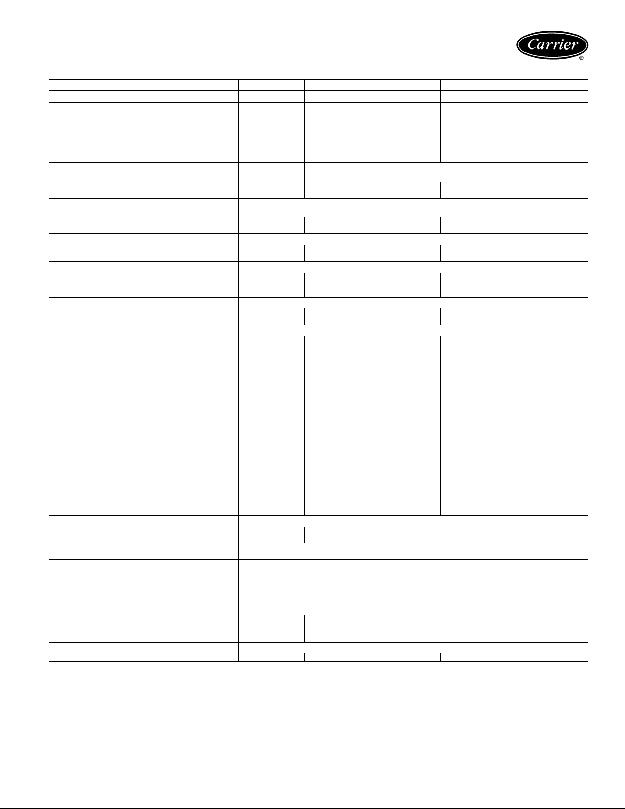
50TFF007-014 UNITS
UNIT SIZE 50TFF 007 008 009 012 014
NOMINAL CAPACITY (tons) 5 6.1 6.9 8.3 10.2
OPERATING WEIGHT (lb)
Unit
Al/Al* 470 755 760 915 930
Al/Cu* 540 825 830 985 1000
Durablade Economizer 34 44 44 44 44
EconoMi$er 47 62 62 62 62
Roof Curb† 115 143 143 143 143
COMPRESSOR
Type Scroll Reciprocating Scroll
Quantity 12 22 2
Oil (oz) 54 42 ea 65 ea 54 ea 54 ea
REFRIGERANTTYPE R-22
Operating Charge (lb-oz)
Circuit 1 7-8 4-13 6-14 7- 3 8-10
Circuit 2 — 4-14 9- 2 7-13 8- 6
CONDENSER COIL
Rows...Fins/in. 2...17 1...17 2...17 2...17 2...17
Total Face Area (sq ft) 10.42 20.50 18.00 20.47 25.00
CONDENSER FAN Propeller Type
Nominal Cfm 3000 6100 6100 6500 6500
Quantity...Diameter (in.) 1...22.0 2...22 2...22 2...22 2...22
Motor Hp...Rpm
EVAPORATOR COIL
1
/3...960
3
/8-in., Enhanced Copper Tubes, Aluminum Double-Wavy Fins, Acutrol™ Feed Device
Rows...Fins/in. 4...15 3...15 3...15 3...15 4...15
Total Face Area (sq ft) 5.5 8.0 8.0 10.0 11.1
EVAPORATOR FAN Centrifugal Type
Quantity...Size (in.) 1...10 x 10 1...15 x 15 1...15 x 15 1...15 x 15 1...15 x 15
Type Drive Belt Belt Belt Belt Belt
Nominal Cfm 2000 2600 2600 3500 4200
Motor Hp 1
Maximum Continuous Bhp 2.40 2.40 2.40 2.40 3.70
Motor Frame Size 56 56 56 56 56
1
/
2
Fan Rpm Range 930-1205 620-880 620-880 690-900 710-890
Motor Bearing Type Ball Ball Ball Ball Ball
Maximum Allowable Rpm 2100 1600 1600 1600 1600
Motor Pulley Pitch Diameter Min/Max (in.) 2.8/3.8 2.4/3.4 2.8/3.8 2.8/3.8 4.0/5.0
Nominal Motor Shaft Diameter (in.)
Fan Pulley Pitch Diameter (in.) 4.5 7.0 7.0 7.0 8.0
5
/
8
Nominal Fan Shaft Diameter (in.) —— —— —
Belt, Quantity...Type...Length (in.) 1...A...40 1...A...49 1...A...49 1...A...49 1...A...52
Pulley Center Line Distance (in.) 14.7-15.5 16.75-19.25 16.75-19.25 15.85-17.50 15.85-17.50
Speed Change per Full Turn of
Movable Pulley Flange (rpm)
Movable Pulley Maximum Full Turns
From Closed Position
80 50 50 50 44
55 55 5
Factory Setting 55 55 5
Factory Speed Setting (rpm) 930 620 620 690 710
Fan Shaft Diameter at Pulley (in.)
5
/
8
HIGH-PRESSURE SWITCH (psig)
Standard Compressor Internal Relief
(Differential)
500 ± 50 450 ± 50 500 ± 50
Cutout 428
Reset (Auto.) 320
LOW-PRESSURE SWITCH (psig)
Cutout 7±3
Reset (Auto.) 22 ± 7
FREEZEPROTECTION THERMOSTAT
Opens 30 ± 5
Closes 45 ± 5
OUTDOOR-AIR INLET SCREENS Cleanable Cleanable
Quantity...Size (in.) 1...20 x 24 x 1
RETURN-AIR FILTERS Throwaway
Quantity...Size (in.) 2...16 x 25 x 2 4...16 x 20 x 2 4...16 x 20 x 2 4...20 x 20 x 2 4...20 x 20 x 2
LEGEND *Evaporator coil fins/condenser coil fins.
Al — Aluminum
Bhp — Brake Horsepower
BkW — Fan Input Watts x Motor Efficiency
Cu — Copper
3
/8-in., Enhanced Copper Tubes, Aluminum Lanced Fins
1
/4...930
11/
5
/
2
8
1
/4...930
11/
5
/
1
/4...930
2
8
23
5
/
8
1
/4...930
7
/
8
111 1
1...20 x 25 x 1
1...16 x 25 x 1
†Requires the accessory/optional controls upgrade kit.
NOTE: The 50TFF007-014 units have a loss-of-charge/low-pressure
switch (accessory) located in the liquid line.
5
Page 6
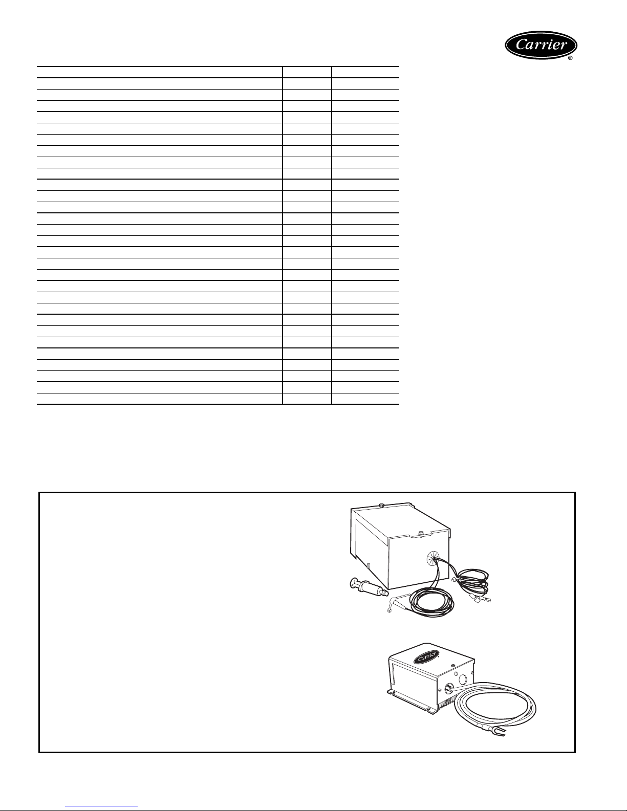
Options and accessories
ITEM OPTION* ACCESSORY†
Apollo Communicating Controls X
Disconnect Switch X
EconoMi$er XX
EconoMi$er with Power Exhaust X
Power Exhaust for EconoMi$er X
Durablade Integrated Economizer (Includes Hood) XX
Manual Outdoor-Air Damper X
Condenser Coil Grille X
Electric Heat X
Electronic Programmable Thermostat X
25% Open Two-Position Damper X
100% Open Two-Position Damper X
Roof Curbs (Vertical and Horizontal Discharge) X
Thermostats and Subbases X
Motormaster® I Head Pressure Control (Speed Control) X
Motormaster II Head Pressure Control (Fan Cycling) X
Time Guard® II Control Circuit X
Thru-the-Bottom Service Connections X
Thru-the-Curb Service Connections X
Accusensor™ II Enthalpy Control X
Accusensor III Enthalpy Sensor X
Condenser Coil Hail Guard Assembly X
Fan/Filter Status X
Salt Spray Protection Grille (008-014) X
Logo Kit X
Outdoor-Air Enthalpy Sensor (EconoMi$er) X
Return-Air Enthalpy Sensor (EconoMi$er) X
Return-Air Temperature Sensor (EconoMi$er) X
Indoor-Aair Quality (CO
*Factory installed.
†Field installed.
) Sensor (EconoMi$er) X
2
HEAD PRESSURE CONTROL
The 50TFF007-014 standard units are designed to operate in cooling at
outdoor temperatures down to –3.8 C (25 F). With accessory Motormaster control (condenser fan speed modulation) or Motormaster II control
(condenser fan cycling) units can operate at outdoor temperatures down
to –17.8 C (0° F). The head pressure controls, which mount in the condenser section, control the condenser-fan motor to maintain correct condensing temperature. Refer to product ordering or contact your local
Carrier representative for appropriate accessory combinations for
desired outdoor ambient temperature operation.
6
Motormaster II Control
(007-014)
Motormaster I Control
(007-014)
Page 7
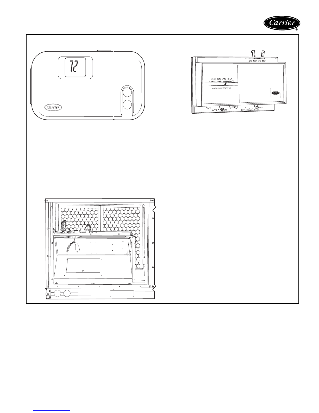
ELECTRONIC PROGRAMMABLE THERMOSTAT
Carrier’s electronic programmable thermostat provides efficient temperature control by allowing you to program heating
and cooling setbacks and setups with provisions for weekends
and holidays. Accessory remote sensing package is also available to provide tamperproof control in high traffic spaces. Used
in conjunction with factory-installed Apollo control, this thermostat provides a 5-minute recycle timer between modes of operation for short-cycle protection.
THERMOSTAT
H
C
Zone thermostat (24 v) provides one- or 2-stage
cooling for control of unit. Matching subbases are
available with or without tamperproof switches and
automatic changeover.
TIME GUARD® II CONTROL
Time Guard II control automatically prevents compressor from restarting for at least 5 minutes after
a shutdown. Accessory prevents short cycling of
compressor if thermostat is changed rapidly. Time
Guard II control mounts in the control compartment
of unit.
DURABLADE ECONOMIZER
Exclusive Durablade economizer damper design saves
energy while providing economical and reliable cooling. A
sliding plate on the face of the economizer controls the
amount of outdoor air entering the system. Closed, it provides a leakproof seal which prevents ambient air from seeping in or conditioned air from seeping out. It can be adjusted
easily for 100% outdoor air or any proportions of mixed air.
Like the base unit, the economizer is converted easily for horizontal discharge applications.
7
Page 8
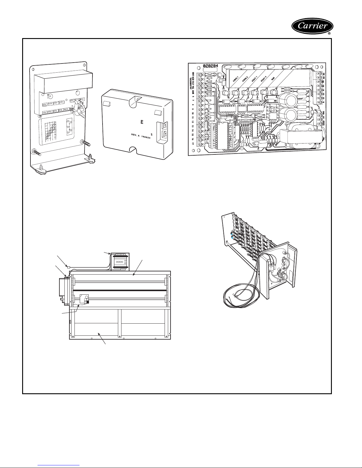
Options and accessories (cont)
MINIMUM
POSITION
OPEN
3
1
T
P
P1
T1
4
2
5
S
S
O
D
C
TR
B
REV
.B
198
818A
%
H
U
M
I
D
I
T
Y
90
70
60
30
10
D
C
B
A
60
65
70
75
55
50
85
80
D
A
M
P
E
R
D
A
M
P
E
R
C
L
O
S
E
D
O
P
E
N
OUTDOORTEMP
.
°
F
REV
.
97-3672
CW
–SETPOINTS
–CCW
C
O
N
T
A
C
T
S
S
H
O
W
N
IN
H
IG
H
E
N
T
H
A
L
P
Y
RUSHA
T24V
AC
3mA
MIN.
A
T1
1VDC
C
O
N
T
A
C
T
R
A
T
IN
G
S
:
1
.5
A
R
U
N
,
3
.5
A
IN
O
R
U
N
P
O
W
E
R
E
D
S
T
A
T
E
1
2
3
TR
T
R
1
24V
AC
ENTHALPYCONTROL
+
ACCUSENSOR™ II
CONTROL
ACCUSENSOR III
SENSOR
Accusensor economizer controls help provide efficient, economical
economizer operation. Accusensor II solid-state enthalpy control
includes the logic and one sensor to calculate both dry- and wetbulb of the outdoor air to provide an accurate enthalpy reading on. It
then decides when to energize the economizer based on this reading. A second Accusensor III sensor compares outdoor temperature
and humidity to return-air temperature and humidity and determines
the most economical mixture of air (purchased in addition to first
solid-state enthalpy sensor for differential enthalpy sensing).
FACTORY-INSTALLED APOLLO
COMMUNICATING CONTROLS
The Apollo direct digital controls are designed exclusively by
Carrier, and are used to actively monitor and control all modes of
operation as well as to monitor evaporator-fan status, filter status,
supply-air temperature, outdoor-air temperature, and indoor-air
quality. They are designed to work in conjunction with Carrier
TEMP and VVT® system thermostats.
ELECTRIC HEATER
ECONOMI$ER
ECONOMI$ER
PLUG
ACTUATOR
OUTDOOR AIR
TEMPERATURE
SENSOR
Factory-installed EconoMi$er utilizes a microprocessor-based control, gear drive damper system, low pressure drop characteristics,
built-in spring return (for close upon power loss), and an integral
barometric damper.
NOTE: EconoMi$er is only available for vertical ductwork applications and can be field or factory installed.
CONTROLLER
BAROMETRIC
RELIEF DAMPERS
GEAR-DRIVEN
DAMPER
Electric heaters are available in a wide range
of capacities for factory or field installation.
8
Page 9
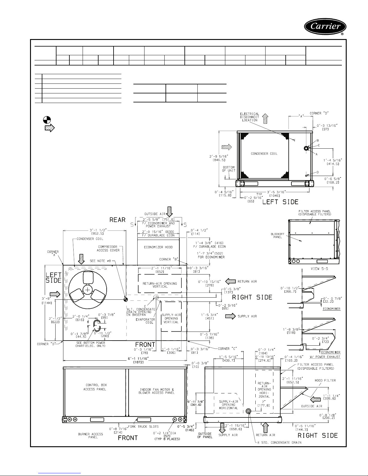
Base unit dimensions — 50TFF007
STD UNIT
UNIT
50TFF007 470 213.2 34 15.4 47 21.3 148 67.1 103 46.7 155 70.3 64 29.0 1′-03/8″ [315.0]
CONNECTION SIZES
A 13/8″ Dia. [35] Field Power Supply Hole
B 2″ Dia. [51] Power Supply Knockout
C 21/2″ Dia. [64] Power Supply Knockout
D7/8″ Dia. [22] Field Control Wiring Hole
E3/4″− 14 NPT Condensate Drain
NOTES:
1. Dimensions in [ ] are in millimeters.
2. Center of gravity.
3. Direction of airflow.
4. On vertical discharge units, ductwork to be attached to accessory roof curb only. For horizontal discharge units field-supplied flanges should be attached to horizontal discharge openings, and all
ductwork should be attached to the flanges.
5. Minimum clearance (local codes or jurisdiction may prevail):
a. Between unit, flue side and combustible surfaces, 36 inches.
b. Bottom of unit to combustible surfaces (when not using curb) 1 inch. Bottom of base rail to com-
c. Condenser coil, for proper airflow, 36 in. one side, 12 in. the other. The side getting the greater
d. Overhead, 60 in. to assure proper condenser fan operation.
e. Between units, control box side, 42 in. per NEC.
f. Between unit and ungrounded surfaces, control box side, 36 in. per NEC.
g. Between unit and block or concrete walls and other grounded surfaces, control box side, 42 in.
h. Horizontal supply and return end, 0 inches.
6. With the exception of the clearance for the condenser coil and combustion side as stated in Note
5a, b, and c, a removable fence or barricade requires no clearance.
7. Units may be installed on combustible floors made from wood or Class A, B, or C roof covering
material if set on base rail.
8. The vertical center of gravity is 1′-6″ [457]
up from the bottom of the base rail.
WEIGHT
Lbs Kg Lbs Kg Lbs Kg Lbs Kg Lbs Kg Lbs Kg Lbs Kg
bustible surfaces (when not using curb) 0 inches.
clearance is optional.
per NEC.
DURABLADE
ECONWEIGHT
ECONOMI$ER
WEIGHT
(A)
CORNER WEIGHT
BOTTOM POWER CHART, THESE HOLES
REQ’D FOR USE WITH ACCESSORY PACKAGES —
CRBTMPWR001A00 (1/2″,3/4″)
THREADED
CONDUIT SIZE
1
/2″
3
/4″
WIRE USE
24 V
Power
(B)
CORNER WEIGHT
REQ’D HOLE
SIZES (Max.)
7
/8″ [22.2]
11/8″ [28.4]
(C)
CORNER WEIGHT
(D)
CORNER WEIGHT
“A”
PANEL
LENGTH
9
Page 10
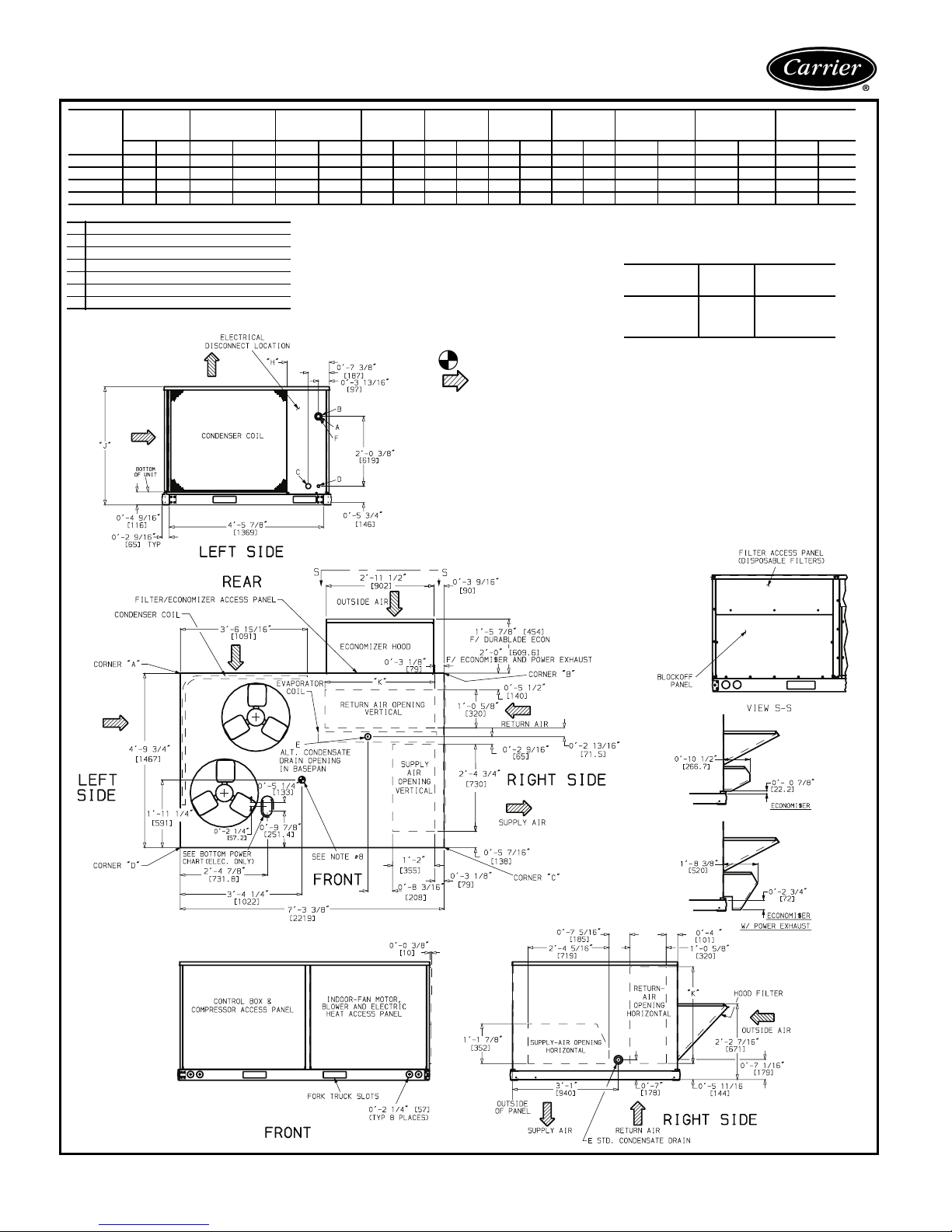
Base unit dimensions — 50TFF008-014
STD UNIT
UNIT
50TFF008 75 5 342 44 20 62 28 164 74 140 64 208 94 243 110 1 -27/8378 3-55/161050 2-911/16856
50TFF009 76 0 345 44 20 62 28 165 75 141 64 209 94 245 111 3 -37/81013 3-55/161050 2-911/16856
50TFF012 91 5 415 44 20 62 28 199 90 170 77 252 114 294 134 2-57/8759 4-15/161253 3-03/8924
50TFF014 930 422 44 20 62 28 202 92 172 78 256 116 3 00 136 1- 27/8378 4-15/161253 3-03/8924
CONNECTION SIZES
A 1
B 21/2″ Dia. [64] Power Supply Knockout
C 13/4″ Dia. [44] Charging Port Hole
D7/8″ Dia. [22] Field Control Wiring Hole
E3/4″ — 14 NPT Condensate Drain
F 2″ Dia. [51] Power Supply Knockout
WEIGHT
Lb Kg Lb Kg Lb Kg Lb Kg Lb Kg Lb Kg Lb Kg Ft-in. mm Ft-in. mm Ft-in. mm
3
/8″ Dia. [35] Field Power Supply Hole
DURABLADE
ECONOMIZER
WEIGHT
ECONOMI$ER
WEIGHT
CORNER
WEIGHT
(A)
CORNER
WEIGHT
(B)
NOTES:
1. Dimensions in [ ] are in millimeters.
2. Center of gravity.
3. D irection of airflow.
4. Ductwork to be attached to accessory roof curb only.
5. Minimum clearance (local codes or jurisdiction may prevail):
a. Bottom to combustible surfaces (when not using curb) 0 inches, on horizontal discharge units with
b. Condenser coil, for proper airflow, 36 in. one side, 12 in. the other. The side getting the greater
c. Overhead, 60 in. to assure proper condenser fan operation.
d. Between units, control box side, 42 in. per NEC (National Electrical Code).
e. Between unit and ungrounded surfaces, control box side, 36 in. per NEC.
f. Between unit and block or concrete walls and other grounded surfaces, control box side, 42 in. per
g. Horizontal supply and return end, 0 inches.
6. With the exception of the clearance for the condenser coil as stated in Notes 5a, b, and c, a removable
fence or barricade requires no clearance.
7. Units may be installed on combustible floors made from wood or Class A, B, or C roof covering material.
8. The vertical center of gravity is 1′-71/2″ [495] for 008 and 009, 2′-0″ [610] for 012 and 014 up from the
bottom of the base rail.
CORNER
WEIGHT
(C)
electric heat 1 in. clearance to ductwork for 1 ft.
clearance is optional.
NEC.
CORNER
WEIGHT
(D)
BOTTOM POWER CHART, THESE HOLES REQ’D
FOR USE WITH ACCESSORY PACKAGES —
THREADED
*Select either3/4″ or 11/4″ for power, depending on wire
size.
“H” “J”“K”
1
WIRE
USE
/2″,3/4″)OR
REQ’D HOLE
SIZES
(Max.)
7
/8″ [22.2]
CRBTMPWR001A00 (
CRBTMPWR002A00 (1/2″,11/4″)
CONDUIT
SIZE
1
/2″ 24 V
3
/4″ Power* 11/8″ [28.4]
1
1
/4″ FPT Power* 13/4″ [44.4]
10
Page 11
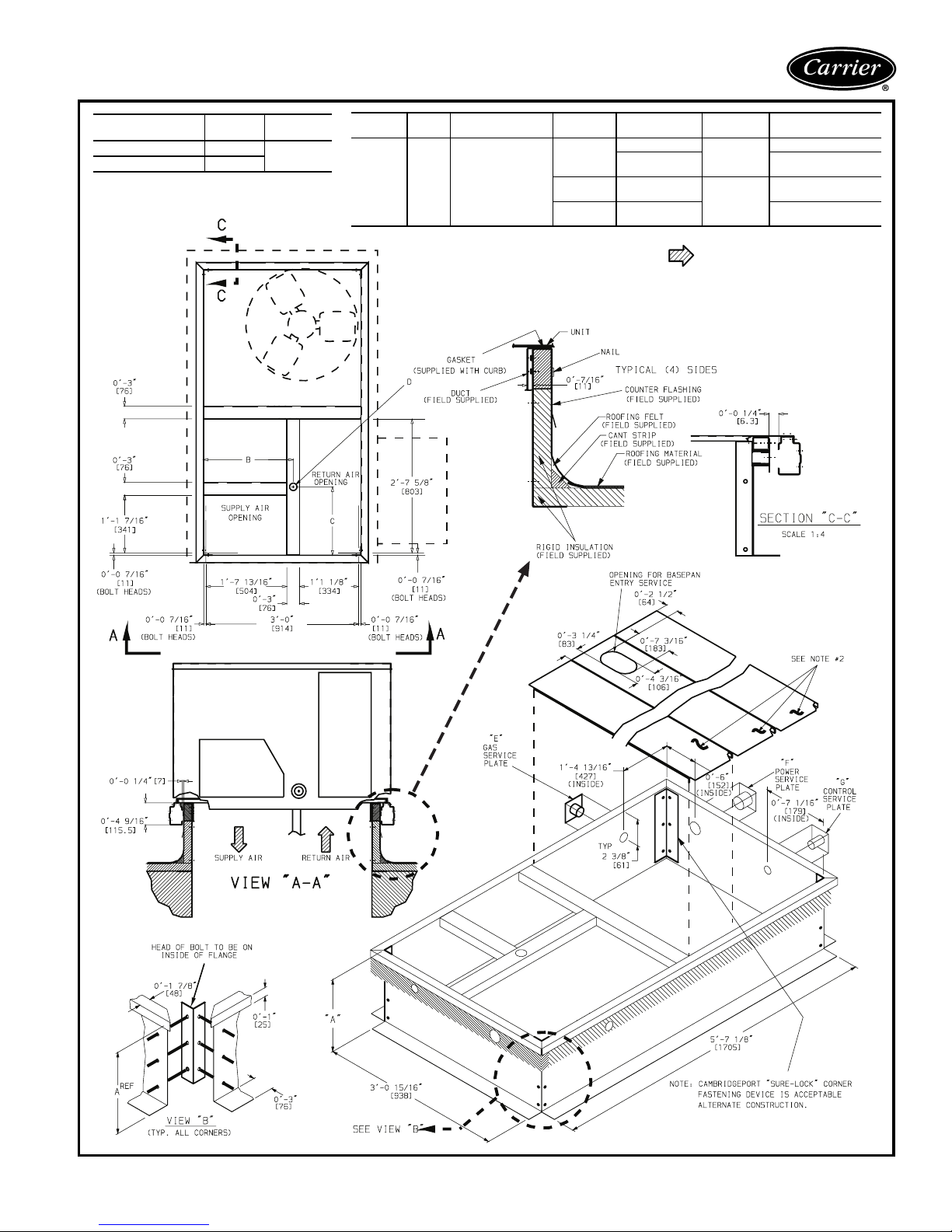
Accessory dimensions
ROOF CURB
ACCESSORY
CRRFCURB001A00 1′-2″ [356]
CRRFCURB002A00 2′-0″ [610]
“A”
UNIT SIZE
50TFF
007
BC
11
/16″
1′-9
[551]
1′-4″
[406]
NOTES:
1. Roof curb accessory is shipped
disassembled.
2. Insulated panels.
3. Dimensions in [ ] are in millimeters.
4. Roof curb: galvanized steel.
5. Attach ductwork to curb (flanges of duct
rest on curb).
D
ALT DRAIN HOLE
13/4″
[44.5]
“E”
GAS
3
/4″
[19] NPT
1
/2″
[12.7] NPT
3
/4″
[19] NPT
“F”
POWER
3
/4″ [19] NPT
1
1
/4″ [31.7]
NPT
3
/4″ [19] NPT
11/4″ [31.7]
NPT
6. Service clearance 4 ft on each side.
7. Direction of airflow.
8. Connector packages CRBTMPWR001A00
and 002A00 are for thru-the-curb connections. Packages CRBTMP003A00 and
004A00 are for thru-the-bottom connections.
“G”
CONTROL
1
/2″
[12.7]
1
/2″
[12.7]
CONNECTOR
PKG.ACCY.
CRBTMPWR001A00
CRBTMPWR002A00
CRBTMPWR003A00
CRBTMPWR004A00
11
Page 12
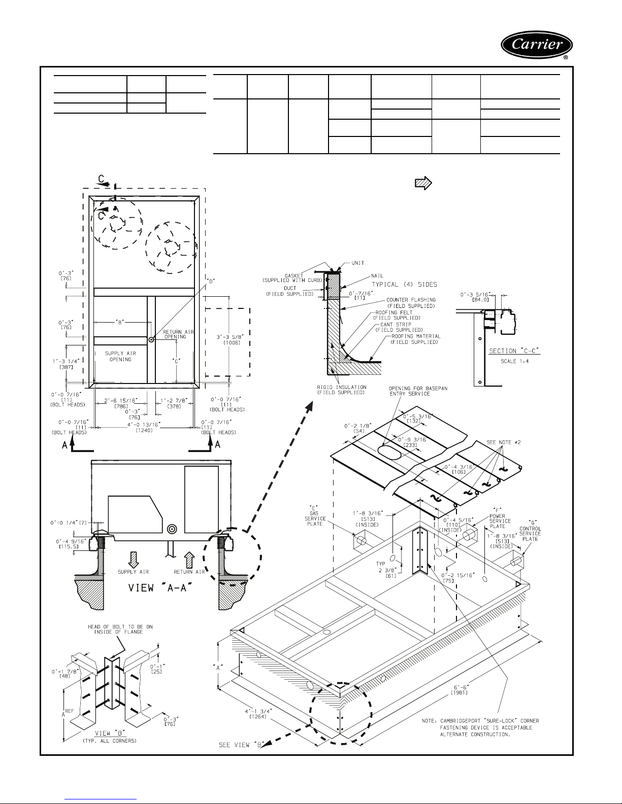
Accessory dimensions (cont)
ROOF CURB
ACCESSORY
“A”
CRRFCURB003A00 1′-2″ [356]
CRRFCURB004A00 2′-0″ [610]
UNIT SIZE
50TFF
008-014
“B” “C”
7
2′-8
/
1′-10
″
16
[827]
[583]
NOTES:
1. Roof curb accessory is shipped
2. Insulated panels, 1″ thick polyurethane
3. Dimensions in [ ] are in millimeters.
4. Roof curb: 16 gage steel.
5. Attach ductwork to curb (flanges of duct
“D”ALT
DRAIN
HOLE
15
/
″
16
[44.5]
disassembled.
3
/4lb density.
foam , 1
rest on curb).
“E”
GAS
3
/4″
/4″
[19] NPT
1
/2″
[12.7] NPT
3
/4″
[19] NPT
3
1
“F”
POWER
3
/4″ [19] NPT
1
/4″ [31.7] NPT CRBTMPWR002A00
1
3
/4″ [19] NPT
11/4″ [31.7] NPT CRBTMPWR004A00
“G”
CONTROL
1
/2″ [12.7]
NPT
1
/2″ [12.7]
NPT
CONNECTOR
PAC KAGE
ACCESSORY
CRBTMPWR001A00
CRBTMPWR003A00
6. Service clearance 4 ft on each side.
7. Direction of airflow.
8. Connector packages CRBTMPWR001A00 and
002A00 are for thru-the-curb connections.
Packages CRBTMP003A00 and 004A00 are
for thru-the-bottom connections.
12
Page 13

Selection procedure (with 50TFF012 example) — SI
I. Determine cooling and heating requirements
at design conditions.
Given:
Required Cooling Capacity (TC) . . . . . . . . . 28 kW
Sensible Heat Capacity (SHC) . . . . . . . . . . 19 kW
Required Heating Capacity . . . . . . . . . . . . 18 kW
Condenser Entering-Air Temp . . . . . . . . . . . 36 C
Evaporator Entering-Air Temp . . . . . . 26.7 C edb,
20 C ewb
Evaporator Air Quantity. . . . . . . . . . . . . 1520 L/s
External Static Pressure (ESP). . . . . . . . . . .300 Pa
Electrical Characteristics (V-Ph-Hz) . . . . . 400-3-50
Edb — Entering dry bulb
Ewb — Entering wet bulb
Durablade economizer required.
II. Select unit based on required cooling
capacity.
Enter the 50TFF012 Cooling Capacities table on
page 18 at condenser entering temperature of
36 C, evaporator-air entering at 1520 L/s, 26.7 C
db and 20 C wb. The 50TFF012 unit will provide
cooling capacity of 30.1 kW and a sensible heat
capacity of 21.2 kW. For evaporator-air temperature other than 26.7 C edb, calculate sensible heat
capacity correction, as required, using the formula
found in the notes following the Cooling Capacities
table on page 19.
NOTE: Unit ratings are gross capacities and do not
include the effect of evaporator-fan motor (IFM)
heat. To calculate net capacities, see Step V.
III. Select electric heat:
Heating load required is 18 kW.
Enter the Electric Heating Capacities table (page 33)
for the 50TFF012 at 400-3-50. The 19.3 kW
heater at 400 v most closely satisfies the heating
required.
IV. Determine fan speed and power require-
ments at design conditions.
Before entering the Fan Performance tables, calculate the total static pressure required based on unit
components. From the given and the Pressure Drop
tables (page 33), find:
External static pressure 300 Pa
Economizer 9 Pa
Electric Heat 14 Pa
Total static pressure 323 Pa
Enter the Fan Performance table for the 50TFF012
vertical discharge unit on page 23. Find the fan r/s
and kilowatts at 323 Pa and 1520 L/s. Note that
the fan speed is 14.5 r/s and power required is
1.56 kW (interpolation required). The standard
motor will adequately handle the job requirements.
V. Determine net capacities.
Capacities are gross and do not include the effect of
evaporator-fan motor heat. Use IFM kW from Fan
Performance table on page 23.
Determine net cooling capacity as follows:
Net capacity = gross capacity – IFM kW
= 30.1 kW – 1.56 kW
= 28.5 kW
Net sensible capacity = 21.2 kW – 1.56 kW
= 19.6 kW
Determine net heating capacity as follows:
Net capacity = gross capacity + IFM heat
= 19.3 kW + 1.56 kW
= 24.9 kW
13
Page 14
Selection procedure (with 50TFF012 example) —
English
I. Determine cooling and heating requirements
at design conditions.
Given:
Required Cooling Capacity (TC) . . . . 96,000 Btuh
Sensible Heat Capacity (SHC) . . . . . .70,000 Btuh
Required Heating Capacity . . . . . . . 62,000 Btuh
Condenser Entering-Air Temp . . . . . . . . . . . 95 F
Evaporator Entering-Air Temp . . . . . . . . 80 F edb,
67 F ewb
Evaporator Air Quantity. . . . . . . . . . . . . 3200 cfm
External Static Pressure (ESP). . . . . . . .1.10 in. wg
Electrical Characteristics (V-Ph-Hz) . . . . . 400-3-50
Edb — Entering dry bulb
Ewb — Entering wet bulb
Durablade economizer required.
II. Select unit based on required cooling
capacity.
Enter the 50TFF012 Cooling Capacities table on
page 21 condenser entering temperature of 95 F,
evaporator-air entering at 3200 cfm, 80 F db and
67 F wb. The 50TFF012 unit will provide cooling
capacity of 102,500 Btuh and a sensible heat
capacity of 76,000 Btuh. For evaporator-air temperature other than 80 F edb, calculate sensible
heat capacity correction, as required, using the formula found in the notes following the Cooling
Capacities table on page 21.
NOTE: Unit ratings are gross capacities and do not
include the effect of evaporator-fan motor (IFM)
heat. To calculate net capacities, see Step V.
III. Select electric heat:
Heating load required is 62,000 Btuh.
62,000 Btuh
3413 Btuh/kW
= 18.2 kW of heat required
IV. Determine fan speed and power require-
ments at design conditions.
Before entering the Fan Performance tables, calculate the total static pressure required based on unit
components. From the given and the Pressure Drop
tables (page 33) find:
External static pressure 1.10 in. wg
Economizer 0.04 in. wg
Electric Heat 0.06 in. wg
Total static pressure 1.20 in. wg
Enter the Fan Performance table for the 50TFF012
vertical discharge unit on page 27. Find the fan rpm
and watts at 1.20 in. wg and 3200 cfm. Note that
the fan speed is 844 rpm and power required is
1430 watts. The standard motor will adequately
handle the job requirements.
V. Determine net capacities.
Capacities are gross and do not include the effect of
evaporator-fan motor heat. Use IFM Watts from Fan
Performance table on page 27.
Determine net cooling capacity as follows:
Net capacity = gross capacity – IFM Watts
= 102,500 Btuh – 1430 Watts x 3.413
= 102,500 Btuh – 4881 Btuh
= 97,619 Btuh
Net sensible capacity = 76,000 Btuh – 4881 Btuh
= 71,119 Btuh
Determine net heating capacity as follows:
Net Capacity= gross capacity + IFM heat
= 65,871 + 4881
= 70,752 Btuh
Btuh
Watts
Enter the Electric Heating Capacities table (page 33)
for the 50TFF012 at 400-3-50. The 19.3 kW
heater at 400 v most closely satisfies the heating
required.
19.3 x 3413 = 65,871 Btuh gross capacity
14
Page 15
Performance data
50TFF007 (17.6 kW)
Temp (C )
Air Entering
Condenser
(Edb)
20
24
28
32
35
40
44
48
52
TC 15.8 17.7 19.6 21.5 16.8 18.7 20.7 22.6 17.4 19.3 21.3 23.3
SHC 15.8 15.5 13.1 10.4 16.8 18.1 14.9 11.6 17.4 19.3 16.6 12.6
kW 3.98 4.11 4.25 4.39 4.08 4.21 4.35 4.49 4.12 4.27 4.41 4.55
TC 15.2 17.1 19.0 20.6 16.2 18.1 20.1 22.0 17.0 18.8 20.7 22.6
SHC 15.2 15.3 12.8 10.2 16.2 17.9 14.7 11.4 17.0 18.8 16.4 12.4
kW 4.26 4.41 4.56 4.71 4.38 4.51 4.66 4.82 4.43 4.58 4.73 4.88
TC 14.7 16.5 18.4 20.3 15.6 17.5 19.4 21.3 16.6 18.2 20.0 21.9
SHC 14.7 15.0 12.6 10.0 15.6 17.5 14.5 11.2 16.6 18.2 16.1 12.2
kW 4.54 4.70 4.87 5.04 4.66 4.82 4.98 5.15 4.74 4.89 5.05 5.21
TC 14.1 15.9 17.8 19.7 15.0 16.9 18.8 20.7 16.2 17.7 19.4 21.2
SHC 14.1 14.7 12.3 9.8 15.0 16.9 14.3 11.0 16.2 17.7 15.8 12.0
kW 4.81 4.99 5.17 5.36 4.92 5.10 5.29 5.48 5.05 5.20 5.37 5.55
TC 13.7 15.5 17.3 19.3 14.5 16.4 18.2 20.2 15.8 17.3 18.8 20.7
SHC 13.7 14.5 12.2 9.6 14.5 16.4 14.1 10.9 15.8 17.3 15.6 11.9
kW 5.01 5.20 5.39 5.60 5.12 5.31 5.52 5.73 5.28 5.61 5.61 5.80
TC 12.7 14.6 16.5 18.3 14.0 15.6 17.3 19.2 15.4 16.6 17.9 19.7
SHC 12.7 14.1 11.8 9.3 14.0 15.6 13.7 10.6 15.4 16.6 15.2 11.6
kW 5.33 5.54 5.76 5.99 5.46 5.68 5.90 6.13 5.68 5.83 5.99 6.20
TC 12.0 13.8 15.8 17.6 13.5 15.1 16.7 18.5 15.1 16.1 17.2 18.9
SHC 12.0 13.8 11.5 9.1 13.5 15.1 13.4 10.3 15.1 16.1 14.8 11.4
kW 5.60 5.82 6.05 6.29 5.75 5.97 6.20 6.45 5.99 6.14 6.31 6.52
TC 11.2 13.1 15.1 16.9 13.0 14.5 15.9 17.7 14.8 15.5 16.5 18.1
SHC 11.2 13.1 11.2 8.8 13.0 14.5 13.1 10.0 14.8 15.5 14.4 11.1
kW 5.85 6.09 6.34 6.60 6.04 6.26 6.50 6.76 6.31 6.46 6.61 6.84
TC 10.5 12.4 14.4 16.2 12.7 13.9 15.3 16.9 14.4 15.0 15.7 17.3
SHC 10.5 12.4 11.0 8.6 12.7 13.9 12.8 9.8 14.4 15.0 14.1 10.9
kW 6.11 6.36 6.63 6.91 6.31 6.56 6.81 7.08 6.62 6.77 6.92 7.16
13 16 192213 16 192213 16 1922
700/0.05 950/0.07 1200/0.09
COOLING CAPACITIES — SI
Air Entering Evaporator — L/s/BF
Air Entering Evaporator — Ewb (C)
LEGEND AND NOTES FOR COOLING CAPACITY TABLES — SI
LEGEND
BF — Bypass Factor
Edb — Entering Dry Bulb Temperature (C)
Ewb — Entering Wet Bulb Temperature (C)
kW — Compressor Input (kW)
SHC — Sensible Heat Capacity (kW)
TC — Total Capacity (kW)
NOTES:
1. Ratings are gross, and do not account for the effects of the
evaporator-fan motor power and heat.
2. Direct interpolation is permissible. Do not extrapolate.
3. SHC is based on 26.7 C db temperature of air entering the unit. At
any other temperature, correct the SHC read from the table of cooling capacities as follows:
Corrected SHC
= SHC + [1.23 x 10–3x(1–BF)x(Cdb– 26.7) x L/s]
Observe the rule of sign. Above 26.7 C, SHC correction will be posi-
tive; add it to SHC. Below 26.7 C, SHC correction will be negative;
subtract it from SHC.
kW
4. Formulas:
SHC
x 1000
kW
C
ldb=Cedb
Leaving wet bulb = wet bulb temperature corresponding to enthalpy
of air leaving coil (h
h
lwb=hewb
Where h
–
1.23 x L/s
).
lwb
TC
x 1000
kW
–
1.20 x L/s
is enthalpy of air entering evaporator coil (kJ/kg).
ewb
15
Page 16
Performance data (cont)
COOLING CAPACITIES — SI (cont)
50TFF008 (21.5 kW)
Temp (C )
Air Entering
Condenser
(Edb)
20
24
28
32
36
40
44
48
52
14 16 1820 22 14 16 1820 22
TC 19.5 20.9 22.5 24.3 26.0 21.6 22.3 23.7 25.3 27.0
SHC 19.4 18.0 16.2 14.3 12.3 21.4 20.5 18.5 16.1 13.4
kW 5.02 5.16 5.34 5.54 5.72 5.28 5.37 5.52 5.70 5.88
TC 19.1 20.4 21.9 23.7 25.4 21.0 21.7 23.1 24.7 26.4
SHC 18.9 17.7 16.0 14.1 12.1 21.0 20.2 18.3 15.9 13.3
kW 5.25 5.38 5.56 5.76 5.96 5.51 5.58 5.74 5.92 6.12
TC 18.6 19.8 21.3 23.0 24.8 20.5 21.1 22.4 24.1 25.9
SHC 18.4 17.3 15.7 13.9 11.9 20.5 19.8 18.0 15.7 13.1
kW 5.49 5.61 5.78 5.98 6.19 5.74 5.8 5.96 6.15 6.36
TC 18.0 19.1 20.6 22.2 23.9 19.9 20.3 21.5 23.2 25.0
SHC 17.8 16.9 15.4 13.6 11.6 19.8 19.4 17.7 15.4 12.9
kW 5.77 5.88 6.04 6.25 6.47 6.03 6.07 6.22 6.43 6.64
TC 17.3 18.2 19.63 21.3 23.0 18.2 19.4 20.6 22.3 24.0
SHC 17.2 16.4 15.0 13.2 11.3 19.1 18.9 17.3 15.0 12.5
kW 6.09 6.18 6.34 6.55 6.77 6.33 6.37 6.61 6.73 6.94
TC 16.6 18.3 18.7 20.3 22.0 18.4 18.6 19.6 21.3 23.0
SHC 16.6 15.9 14.6 12.8 10.9 18.4 18.3 16.9 14.7 12.3
kW 6.40 6.48 6.63 6.84 7.07 6.65 6.67 6.81 7.02 7.24
TC 15.9 16.4 17.7 19.4 21.0 17.7 17.7 18.7 20.2 21.9
SHC 15.9 15.4 14.2 12.5 10.6 17.7 17.6 16.4 14.3 11.9
kW 6.71 6.77 6.92 7.13 7.36 6.97 6.97 7.10 7.30 7.53
TC 15.2 15.5 16.7 18.3 19.9 16.9 16.9 17.7 19.1 20.7
SHC 15.2 14.9 13.8 12.1 10.2 16.9 16.9 15.8 13.9 11.5
kW 7.02 7.05 7.20 7.41 7.64 7.27 7.27 7.39 7.57 7.81
TC 14.4 14.5 15.6 17.3 18.8 16.1 16.1 16.8 18.0 19.6
SHC 14.4 14.3 13.3 11.7 9.9 16.1 16.1 15.2 13.5 11.2
kW 7.33 7.33 7.47 7.67 7.91 7.56 7.57 7.67 7.85 8.08
850/0.05 1130/0.075
Air Entering Evaporator — L/s BF
Air Entering Evaporator — Ewb (C)
50TFF008 (21.5 kW)(cont)
Temp (C )
Air Entering
Condenser
(Edb)
20
24
28
32
36
40
44
48
52
TC 21.8 22.5 23.9 25.5 27.1 22.9 23.1 24.3 26.1 27.7
SHC 21.8 20.9 18.9 16.4 13.6 22.8 22.4 20.5 17.7 14.5
kW 5.33 5.41 5.55 5.73 5.91 5.49 5.51 5.65 5.83 5.99
TC 21.3 21.9 23.3 24.9 26.5 22.4 22.5 23.7 25.4 27.0
SHC 21.2 20.6 18.7 16.2 13.5 22.3 22.0 20.2 17.5 14.3
kW 5.55 5.62 5.77 5.96 6.14 5.72 5.73 5.86 6.05 6.22
TC 20.8 21.2 22.5 24.2 25.9 21.8 21.9 23.1 24.7 26.4
SHC 20.7 20.2 18.4 16.0 13.3 21.8 21.7 20.0 17.3 14.1
kW 5.78 5.84 5.98 6.17 6.38 5.94 5.96 6.08 6.28 6.46
TC 20.2 20.5 21.7 23.4 25.2 21.2 21.2 22.2 23.8 25.6
SHC 20.2 19.8 18.1 15.7 13.0 21.2 21.0 19.5 17.0 13.9
kW 6.07 6.11 6.25 6.45 6.66 6.23 6.23 6.36 6.54 6.74
TC 19.5 19.6 20.7 22.4 24.1 20.4 20.4 20.7 22.8 24.6
SHC 19.4 19.2 17.7 15.3 12.7 20.4 20.4 19.0 16.6 13.6
kW 6.39 6.41 6.55 6.75 6.96 6.54 6.54 6.66 6.84 7.05
TC 18.7 18.7 19.8 21.3 23.1 19.6 19.6 20.4 21.7 23.4
SHC 18.7 18.6 17.2 15.0 12.4 19.6 19.6 18.4 16.3 13.3
kW 6.69 6.70 6.83 7.04 7.26 6.86 6.86 6.95 7.12 7.34
TC 17.9 17.9 18.8 20.3 22.0 18.8 18.8 19.4 20.6 22.3
SHC 17.9 17.9 16.7 14.6 12.1 18.8 18.8 17.8 15.9 13.0
kW 7.01 7.01 7.13 7.33 7.55 7.16 7.16 7.25 7.41 7.64
TC 17.1 17.1 17.9 19.2 20.8 17.9 17.9 18.5 19.5 21.2
SHC 17.1 17.1 16.1 14.2 11.7 17.9 17.9 17.2 15.5 12.7
kW 7.31 7.31 7.42 7.59 7.83 7.46 7.47 7.54 7.69 7.92
TC 16.3 16.3 16.9 18.0 19.6 17.1 17.1 17.4 18.3 19.9
SHC 16.3 16.3 15.4 13.9 11.4 17.1 17.1 16.5 15.1 12.3
kW 7.61 7.61 7.70 7.87 8.1 7.76 7.77 7.82 7.95 8.18
Air Entering Evaporator — L/s BF
1180/0.075 1400/0.095
Air Entering Evaporator — Ewb (C)
14 16 1820 22 14 16 1820 22
16
Page 17
50TFF009 (24.3 kW)
Temp (C )
Air Entering
Condenser
(Edb)
20
TC 24.7 25.2 28.4 30.8 26.0 26.2 29.1 31.5 27.9 27.9 29.9 32.2
SHC 24.1 23.2 19.3 15.0 25.2 24.6 20.5 15.5 26.5 26.5 22.0 16.0
kW 6.25 6.38 6.60 6.70 6.60 6.68 6.97 7.06 7.25 7.25 7.66 7.73
24
TC 24.0 24.3 27.5 30.3 25.5 25.5 28.4 30.9 27.1 27.1 29.3 31.6
SHC 23.4 22.8 19.0 14.8 24.6 24.3 20.4 15.4 25.7 25.8 22.0 16.0
kW 6.61 6.69 6.96 7.09 6.97 7.02 7.35 7.46 7.61 7.60 8.04 8.14
28
TC 23.0 23.2 26.5 29.6 24.7 24.7 27.5 30.3 26.4 26.4 28.4 31.0
SHC 22.5 22.0 18.7 14.6 23.9 23.9 20.1 15.2 25.0 25.0 21.8 15.9
kW 7.00 7.06 7.33 7.48 7.34 7.34 7.71 7.86 7.98 7.97 8.42 8.55
32
TC 22.3 22.4 25.5 28.7 23.7 23.7 26.3 29.4 25.6 25.6 27.3 30.2
SHC 21.7 21.4 18.4 14.3 22.8 22.8 19.7 15.0 24.2 24.2 21.5 15.7
kW 7.32 7.36 7.71 7.87 7.72 7.72 8.09 8.25 8.37 8.36 8.77 8.96
35
TC 21.7 21.7 24.6 28.0 23.1 23.0 25.6 28.7 25.0 25.0 26.4 29.4
SHC 21.1 20.9 17.9 14.1 22.2 22.2 19.5 14.8 23.6 23.6 21.2 15.4
kW 7.56 7.59 8.01 8.17 8.00 7.99 8.37 8.57 8.66 8.65 9.03 9.27
40
TC 20.7 20.7 23.1 26.7 22.0 22.0 23.9 27.4 23.6 23.6 25.0 28.2
SHC 20.1 20.1 17.4 13.6 21.2 21.2 18.8 14.3 22.2 22.2 20.7 15.1
kW 7.96 7.96 8.44 8.66 8.42 8.41 8.82 9.06 9.15 9.14 9.47 9.78
44
TC 19.9 19.9 22.0 25.5 21.2 21.2 22.7 26.3 22.7 22.7 23.7 27.0
SHC 19.3 19.3 16.9 13.2 20.3 20.3 18.3 14.0 21.3 21.3 20.2 14.8
kW 8.29 8.29 8.78 9.04 8.75 8.75 9.15 9.44 9.52 9.51 9.80 10.17
48
TC 19.1 19.1 20.8 24.3 20.3 20.3 21.5 25.0 21.8 21.8 22.3 25.8
SHC 18.5 18.5 16.4 12.8 19.4 19.4 17.8 13.5 20.4 20.4 19.5 14.4
kW 8.62 8.62 9.05 9.42 9.08 9.08 9.48 9.83 9.88 9.87 10.10 10.56
COOLING CAPACITIES — SI (cont)
Air Entering Evaporator — L/s/BF
1200/0.07 1400/.08 1700/0.11
Air Entering Evaporator — Ewb (C)
13 16 192213 16 192213 16 1922
LEGEND AND NOTES FOR COOLING CAPACITY TABLES — SI
LEGEND
BF — Bypass Factor
Edb — Entering Dry Bulb Temperature (C)
Ewb — Entering Wet Bulb Temperature (C)
kW — Compressor Input (kW)
SHC — Sensible Heat Capacity (kW)
TC — Total Capacity (kW)
NOTES:
1. Ratings are gross, and do not account for the effects of the
evaporator-fan motor power and heat.
2. Direct interpolation is permissible. Do not extrapolate.
3. SHC is based on 26.7 C db temperature of air entering the unit. At
any other temperature, correct the SHC read from the table of cooling capacities as follows:
Corrected SHC
= SHC + [1.23 x 10–3x(1–BF)x(Cdb– 26.7) x L/s]
Observe the rule of sign. Above 26.7 C, SHC correction will be posi-
tive; add it to SHC. Below 26.7 C, SHC correction will be negative;
subtract it from SHC.
kW
4. Formulas:
SHC
x 1000
kW
C
ldb=Cedb
Leaving wet bulb = wet bulb temperature corresponding to enthalpy
of air leaving coil (h
h
lwb=hewb
Where h
–
1.23 x L/s
).
lwb
TC
x 1000
kW
–
1.20 x L/s
is enthalpy of air entering evaporator coil (kJ/kg).
ewb
17
Page 18
Performance data (cont)
COOLING CAPACITIES — SI (cont)
50TFF012 (29.2 kW)
Temp (C )
Air Entering
Condenser
(Edb)
20
24
28
32
36
40
44
48
52
14 16 1820 22 14 16 1820 22
TC 26.6 28.2 30.5 33.1 34.7 30.5 31.4 32.7 34.3 36.3
SHC 26.4 24.8 22.8 20.3 17.3 30.4 29.3 26.2 22.2 18.7
kW 6.82 6.98 7.17 7.35 7.42 7.09 7.17 7.27 7.39 7.60
TC 25.8 27.0 29.4 32.1 33.8 29.6 30.4 31.8 33.5 35.3
SHC 25.6 24.2 22.3 19.9 16.8 29.5 28.7 25.9 22.2 18.4
kW 7.20 7.34 7.54 7.73 7.82 7.47 7.53 7.65 7.80 7.99
TC 24.7 25.8 28.2 30.8 32.8 28.5 29.1 30.7 32.6 34.4
SHC 24.6 23.5 21.7 19.4 16.4 28.5 27.9 25.4 21.9 18.2
kW 7.61 7.93 8.11 8.32 8.45 8.09 8.12 8.26 8.46 8.64
TC 23.6 24.5 26.6 29.4 31.8 27.3 27.7 29.4 31.5 33.3
SHC 23.5 22.7 21.1 18.8 16.1 27.3 27.0 24.8 21.6 17.8
kW 8.03 8.13 8.31 8.53 8.67 8.30 8.32 8.47 8.67 8.85
TC 22.4 23.0 25.0 27.9 30.7 26.1 26.3 27.9 30.1 32.0
SHC 22.3 21.8 20.3 18.2 17.8 26.0 26.0 24.1 21.2 17.4
kW 8.47 8.53 8.73 8.96 9.15 8.74 8.74 8.89 9.11 9.30
TC 21.1 21.5 23.4 26.2 29.5 24.7 24.7 26.4 28.7 30.8
SHC 21.1 20.9 19.6 17.5 15.3 24.7 24.7 23.3 20.7 17.2
kW 8.95 8.97 9.15 9.40 9.64 9.20 9.20 9.34 9.56 9.80
TC 20.0 20.1 21.7 24.4 27.9 23.1 23.1 24.4 26.6 29.4
SHC 20.0 19.9 18.7 16.8 14.8 23.1 23.1 22.0 20.0 16.7
kW 9.40 9.40 9.60 9.86 10.11 9.70 9.71 9.82 10.03 10.29
TC 19.1 19.1 20.3 22.6 26.0 21.5 21.5 22.4 24.3 27.6
SHC 10.1 19.1 17.9 16.2 14.2 21.5 21.5 20.7 19.1 16.2
kW 9.89 9.89 10.06 10.32 10.59 10.22 10.22 10.31 10.50 10.79
TC 18.3 18.3 19.1 20.9 24.0 20.0 20.0 20.4 21.9 25.5
SHC 18.3 18.3 17.2 15.5 13.5 20.0 20.0 18.4 18.1 15.5
kW 10.37 10.37 10.52 10.77 11.07 10.74 10.74 10.81 10.98 11.28
1140/0.08 1520/0.105
Air Entering Evaporator — L/s BF
Air Entering Evaporator — Ewb (C)
50TFF012 (29.2 kW)(cont)
Temp (C )
Air Entering
Condenser
(Edb)
TC 31.5 31.9 33.3 35.3 37.2 31.7 23.1 33.5 35.3 37.3
20
24
28
32
36
40
44
48
52
SHC 31.4 30.6 27.8 24.0 19.9 31.7 31.1 28.3 24.4 20.2
kW 7.12 7.16 7.30 7.50 7.70 7.15 7.18 7.32 7.51 7.71
TC 30.8 31.0 32.4 34.2 36.2 31.0 31.2 32.5 34.4 36.2
SHC 30.8 30.1 27.4 23.6 19.6 31.0 30.5 27.9 24.0 19.7
kW 7.53 7.54 7.68 7.88 8.10 7.54 7.57 7.71 7.90 8.09
TC 30.0 30.1 31.4 33.2 35.2 30.3 30.4 31.6 33.3 35.0
SHC 30.0 29.6 27.2 23.4 19.3 30.2 30.1 27.6 23.7 19.5
kW 7.95 7.97 8.11 8.30 8.51 7.99 7.99 8.13 8.31 8.51
TC 29.1 29.1 30.3 32.1 34.0 29.4 29.4 30.5 32.2 34.0
SHC 29.1 29.0 26.7 23.1 18.9 29.4 29.4 27.1 23.5 19.2
kW 8.40 8.41 8.54 8.73 8.95 8.44 8.44 8.56 8.75 8.95
TC 28.1 28.0 29.1 30.8 32.8 28.3 28.3 29.3 31.0 32.9
SHC 27.9 28.0 26.1 22.8 18.5 28.3 28.3 26.5 23.3 18.9
kW 8.87 8.87 8.89 9.17 9.40 8.91 8.91 9.01 9.19 9.42
TC 26.5 26.5 27.7 29.5 31.5 27.0 27.0 28.0 29.7 31.6
SHC 14.7 26.5 25.1 22.5 18.3 26.9 27.0 25.6 23.0 18.6
kW 9.37 9.36 9.46 9.64 9.88 9.41 9.40 9.50 9.66 9.89
TC 24.8 24.8 25.7 27.5 30.0 25.2 25.2 26.1 27.7 30.1
SHC 24.8 24.8 23.8 21.8 18.0 25.2 25.2 24.4 22.3 18.2
kW 9.87 9.87 9.96 10.12 10.36 9.92 9.92 9.99 10.13 10.38
TC 23.0 23.0 23.7 25.3 28.3 23.4 23.4 24.0 25.5 28.4
SHC 23.0 23.0 22.4 20.9 17.5 23.4 23.4 23.0 21.4 17.8
kW 10.39 10.39 10.45 10.59 10.86 10.43 10.43 10.49 10.61 10.90
TC 21.3 21.3 21.6 22.8 26.5 21.6 21.6 21.8 23.0 26.7
SHC 21.3 21.3 21.0 19.9 17.0 21.6 21.6 21.4 20.4 17.4
kW 10.93 10.93 10.95 11.07 11.38 10.97 10.97 10.99 11.10 11.41
Air Entering Evaporator — L/s BF
1800/0.1251880/0.13
Air Entering Evaporator — Ewb (C)
14 16 1820 22 14 16 1820 22
18
Page 19
50TFF014 (35.9 kW)
Temp (C )
Air Entering
Condenser
(Edb)
20
TC 34.7 38.0 41.4 44.4 37.0 40.0 43.2 46.3 36.6 40.1 43.6 46.7
SHC 34.7 33.8 28.1 22.0 37.0 39.9 31.7 24.0 36.6 40.1 33.5 25.0
kW 8.92 8.99 9.08 9.13 9.00 9.06 9.13 9.22 9.05 9.10 9.15 9.25
24
TC 32.1 35.8 39.6 43.0 34.8 38.2 41.6 44.9 35.5 38.7 42.1 45.5
SHC 32.1 32.8 27.4 21.6 34.8 38.2 31.1 23.7 35.5 38.7 32.4 24.8
kW 9.34 9.46 9.60 9.70 9.47 9.57 9.68 9.80 9.60 9.63 9.74 9.84
28
TC 29.4 33.6 37.9 41.6 32.9 36.3 40.0 43.4 34.4 37.4 40.6 44.0
SHC 29.4 31.9 26.7 21.1 32.9 36.3 30.5 23.3 34.4 37.4 32.5 24.6
kW 9.78 9.94 10.12 10.27 9.95 10.08 10.22 10.39 10.15 10.10 10.25 10.42
32
TC 26.7 31.5 36.2 40.2 30.8 34.5 38.3 42.0 33.0 36.0 39.1 42.7
SHC 26.7 30.9 26.0 20.7 30.8 34.5 29.9 22.9 33.0 36.0 31.9 24.3
kW 10.20 10.42 10.64 10.85 10.40 10.59 10.76 10.96 10.49 10.65 10.82 11.01
35
TC 24.7 29.9 34.9 39.1 29.2 33.1 37.0 40.9 31.4 35.0 38.0 41.6
SHC 24.7 29.7 25.5 20.3 29.2 33.1 29.4 22.7 31.4 35.0 31.5 24.2
kW 10.52 10.80 11.03 11.30 10.77 11.00 11.18 11.40 10.40 11.07 11.25 11.47
40
TC 21.1 26.8 32.3 37.1 26.9 30.8 34.7 38.8 30.5 53.1 35.8 39.5
SHC 21.1 26.8 24.4 19.7 26.9 30.8 28.3 22.1 30.5 33.1 30.6 23.7
kW 11.10 11.40 11.71 12.00 11.42 11.64 11.88 12.13 11.64 11.79 11.96 12.20
44
TC 20.5 25.3 30.2 35.2 25.7 28.8 32.2 36.9 29.1 31.0 33.4 37.6
SHC 20.5 25.3 23.5 19.1 25.7 28.8 27.1 21.5 29.1 31.0 29.4 23.2
kW 11.62 11.93 12.25 12.58 12.05 12.24 12.44 12.73 12.26 12.38 12.52 12.79
48
TC 20.4 24.1 27.9 33.2 24.5 26.9 29.6 34.9 27.7 29.0 30.8 35.5
SHC 20.4 24.1 27.9 33.2 24.5 26.9 25.8 21.0 27.7 29.0 28.1 22.6
kW 12.15 12.45 12.78 13.17 12.68 12.84 13.00 13.33 12.88 12.97 13.10 13.39
52
TC 20.1 22.8 25.8 31.3 23.3 24.9 27.0 33.1 26.2 26.9 28.2 33.5
SHC 20.1 22.8 21.4 17.8 23.3 24.9 24.5 20.3 26.0 26.8 26.7 22.1
kW 12.67 12.98 13.31 13.75 13.34 13.43 13.56 13.93 13.49 13.57 13.67 13.97
COOLING CAPACITIES — SI (cont)
Air Entering Evaporator — L/s/BF
1500/0.132000/0.17 2350/0.21
Air Entering Evaporator — Ewb (C)
13 16 192213 16 192213 16 1922
LEGEND AND NOTES FOR COOLING CAPACITY TABLES — SI
LEGEND
BF — Bypass Factor
Edb — Entering Dry Bulb Temperature (C)
Ewb — Entering Wet Bulb Temperature (C)
kW — Compressor Input (kW)
SHC — Sensible Heat Capacity (kW)
TC — Total Capacity (kW)
NOTES:
1. Ratings are gross, and do not account for the effects of the
evaporator-fan motor power and heat.
2. Direct interpolation is permissible. Do not extrapolate.
3. SHC is based on 26.7 C db temperature of air entering the unit. At
any other temperature, correct the SHC read from the table of cooling capacities as follows:
Corrected SHC
= SHC + [1.23 x 10–3x(1–BF)x(Cdb– 26.7) x L/s]
Observe the rule of sign. Above 26.7 C, SHC correction will be posi-
tive; add it to SHC. Below 26.7 C, SHC correction will be negative;
subtract it from SHC.
kW
4. Formulas:
SHC
x 1000
kW
C
ldb=Cedb
Leaving wet bulb = wet bulb temperature corresponding to enthalpy
of air leaving coil (h
h
lwb=hewb
Where h
–
1.23 x L/s
).
lwb
TC
x 1000
kW
–
1.20 x L/s
is enthalpy of air entering evaporator coil (kJ/kg).
ewb
19
Page 20

Performance data (cont)
COOLING CAPACITIES — ENGLISH
50TFF007 (5 TONS)
Tem p ( F)
Air Entering
Condenser
(Edb)
75
85
95
105
115
125
50TFF008 (6.1 TONS)
Tem p ( F)
Air Entering
Condenser
75
85
95
105
115
125
TC 60.0 66.0 72.1 63.0 69.2 76.1 65.2 71.5 78.1
SHC 50.5 42.6 34.5 58.2 48.5 38.3 64.3 54.0 41.3
kW 4.44 4.57 4.71 4.52 4.66 4.84 4.58 4.74 4.90
TC 57.2 63.2 69.4 60.3 66.3 72.4 62.6 68.0 74.3
SHC 49.4 41.6 33.5 57.3 47.5 37.1 62.6 52.8 39.9
kW 4.85 5.00 5.17 4.96 5.11 5.28 5.03 5.18 5.34
TC 54.4 60.2 66.3 57.1 62.9 69.4 60.0 64.7 70.9
SHC 48.1 40.4 32.4 55.6 46.4 36.2 60.0 52.0 39.3
kW 5.25 5.43 5.62 5.35 5.54 5.75 5.47 5.62 5.81
TC 51.0 56.9 62.9 54.2 59.5 65.7 57.2 61.1 67.1
SHC 46.5 39.1 31.2 53.5 45.2 35.0 57.2 50.7 38.2
kW 5.64 5.83 6.05 5.76 5.97 6.19 5.90 6.05 6.26
TC 47.6 53.7 59.5 51.4 56.0 62.0 54.4 57.4 63.3
SHC 45.0 37.8 30.0 51.3 44.0 33.8 54.4 49.4 37.0
kW 6.02 6.24 6.48 6.17 6.39 6.63 6.33 6.48 6.70
TC 44.7 50.3 55.8 48.7 52.3 58.0 51.6 53.5 59.2
SHC 43.5 36.6 28.8 48.7 42.5 32.4 51.6 47.7 35.9
kW 6.39 6.65 6.90 6.61 6.77 7.03 6.79 6.87 7.12
(Edb)
TC 71.9 80.1 88.3 74.9 83.0 90.9 75.3 83.6 91.3 77.4 85.2 92.9
SHC 56.3 46.6 55.1 62.3 50.5 57.0 63.6 51.2 60.4 69.1 55.3 23.7
kW 5.47 5.73 6.02 5.60 5.86 6.14 5.64 5.90 6.14 5.74 6.00 6.24
TC 69.0 77.1 85.4 71.7 79.8 88.2 72.2 80.2 88.5 74.3 82.0 90.0
SHC 59.7 50.5 40.6 66.6 55.6 43.6 68.0 56.6 44.1 73.8 62.0 47.0
kW 5.77 6.04 6.34 5.90 6.17 6.47 5.93 6.19 6.49 6.05 6.31 6.57
TC 64.9 72.7 80.8 67.4 75.2 83.5 67.8 75.6 83.8 70.7 77.1 85.5
SHC 57.9 48.8 39.1 64.6 54.0 42.1 65.8 55.1 42.7 70.5 60.2 45.9
kW 6.32 6.61 6.54 6.45 6.75 6.60 6.48 6.76 6.69 6.60 6.86 3.46
TC 60.4 68.1 76.2 63.0 70.4 78.6 63.5 70.8 78.8 66.7 72.0 80.1
SHC 55.7 47.2 37.5 62.2 52.4 40.8 63.2 53.4 41.3 66.7 58.6 44.1
kW 6.59 6.86 7.19 6.71 7.00 7.32 6.74 7.02 7.34 6.90 7.11 7.40
TC 55.9 63.4 71.1 59.0 65.4 73.2 59.7 65.6 73.5 62.5 66.8 75.0
SHC 53.2 45.4 35.9 59.0 50.6 39.0 59.7 51.6 39.6 62.7 56.8 43.0
kW 6.99 7.26 7.58 7.13 7.39 7.71 7.17 7.41 7.72 7.34 7.49 7.83
TC 51.1 58.4 65.8 55.1 60.0 67.7 55.8 60.3 57.9 58.7 61.3 69.0
SHC 50.4 43.5 34.1 55.0 48.6 37.3 55.8 49.8 37.9 58.6 54.8 41.3
kW 7.37 7.63 7.95 7.54 7.75 8.08 7.58 6.77 8.10 7.75 7.87 8.20
1500/0.05 2000/0.07 2500/0.09
62 6772626772626772
1950/0.062400/0.075 2500/0.075 3000/0.095
62 6772626772626772626772
Air Entering Evaporator — Cfm/BF
Air Entering Evaporator — Ewb (F)
Air Entering Evaporator — Cfm/BF
Air Entering Evaporator — Ewb (F)
50TFF009 (6.9 TONS)
Tem p ( F)
Air Entering
Condenser
(Edb)
75
85
95
105
115
125
TC 79.2 90.1 99.5 85.0 95.2 103.7 88.9 98.5 106.4 92.3 100.9 108.4
SHC 65.7 56.4 46.2 74.9 62.5 49.2 81.9 67.3 51.4 86.0 71.2 52.8
kW 6.44 6.56 6.68 6.76 6.93 7.06 7.12 7.39 7.49 7.56 7.93 8.03
TC 74.6 85.8 96.0 79.4 90.6 100.2 84.4 94.3 103.0 88.3 96.7 105.0
SHC 63.7 54.8 44.9 72.2 60.8 48.1 78.9 66.0 50.5 83.9 70.3 52.2
kW 6.85 7.06 7.21 7.25 7.46 7.59 7.59 7.90 8.04 8.01 8.45 8.59
TC 70.2 80.4 91.4 74.7 82.9 96.1 79.1 84.1 98.9 84.5 91.5 100.7
SHC 61.6 52.5 43.2 69.6 59.2 46.8 75.3 64.4 49.3 80.1 68.7 51.0
kW 7.26 7.58 7.75 7.62 7.98 8.15 8.08 8.43 8.60 8.53 8.99 9.15
TC 65.5 75.6 86.8 70.4 79.9 91.0 75.1 83.0 93.9 79.3 85.9 95.9
SHC 59.3 50.5 41.6 55.4 56.7 45.0 72.2 61.8 47.7 75.0 67.0 49.7
kW 7.64 8.05 8.28 8.03 8.50 8.69 8.50 8.98 9.16 9.07 9.48 9.71
TC 60.7 70.5 81.7 66.0 74.4 85.6 70.9 77.3 88.4 75.0 79.5 90.5
SHC 56.5 48.5 39.8 63.5 54.5 43.2 68.0 59.8 45.9 70.6 64.3 48.0
kW 8.01 8.47 8.81 8.45 8.96 9.21 8.96 9.44 9.69 9.57 10.00 10.27
TC 45.4 65.1 75.7 61.8 68.7 79.9 66.6 71.3 82.6 70.6 73.3 84.5
SHC 53.6 46.3 37.5 60.0 52.4 41.3 63.7 57.6 44.0 66.2 61.9 46.1
kW 8.43 8.90 9.35 8.88 9.39 9.77 9.43 9.88 10.26 10.06 10.41 10.81
2000/0.07 2500/.083000/0.10 3500/0.11
62 6772626772626772626772
20
Air Entering Evaporator — Cfm/BF
Air Entering Evaporator — Ewb (F)
Page 21
50TFF012 (8.3 TONS)
Tem p ( F)
Air Entering
Condenser
(Edb)
75
85
95
105
115
125
TC 95.1 108.3 116.7 104.5 112.8 121.4 106.2 114.9 124.4 107.0 115.8 124.2
SHC 77.4 64.2 77.2 87.6 70.1 82.0 101.9 74.6 84.7 95.0 75.9 32.4
kW 7.39 7.69 7.83 7.55 7.74 8.00 7.5 7.81 8.10 7.56 7.84 8.10
TC 88.9 102.3 112.0 98.5 108.3 116.9 101.8 110.3 119.2 102.7 110.8 119.0
SHC 79.9 69.3 55.1 93.5 77.7 60.0 100.3 83.4 63.7 102.2 85.1 64.4
kW 7.91 8.24 8.42 8.08 8.34 8.60 8.10 8.39 8.69 8.15 8.41 8.67
TC 81.8 94.7 107.2 91.2 102.5 110.9 96.8 104.4 113.7 98.0 105.0 114.2
SHC 76.4 66.2 53.8 89.5 76.0 58.1 96.7 82.1 61.4 98.0 83.9 63.2
kW 8.64 8.94 8.85 8.77 9.08 8.96 8.8 9.15 9.03 8.91 9.17 4.60
TC 74.2 86.4 101.8 83.4 95.2 105.3 89.7 98.2 107.6 91.3 98.7 108.0
SHC 72.1 62.8 51.8 83.4 73.4 56.9 89.7 80.5 60.8 91.3 82.6 61.7
kW 9.06 9.42 9.74 9.26 9.56 9.88 9.4 9.65 9.96 9.48 9.66 9.98
TC 67.4 77.2 94.2 75.6 83.8 99.0 81.3 87.4 100.6 82.8 88.4 101.0
SHC 67.3 59.1 49.5 75.6 68.9 55.1 81.2 76.3 59.0 82.7 78.7 60.1
kW 9.71 10.04 10.42 9.97 10.19 10.59 10.1 10.28 10.66 10.19 10.31 10.68
TC 63.2 69.2 84.4 68.5 71.8 88.8 73.1 75.0 92.3 74.2 76.0 93.0
SHC 63.2 56.0 46.0 68.5 64.3 51.9 73.0 70.9 56.9 74.2 73.0 58.4
kW 10.37 10.68 11.09 10.69 10.85 11.27 10.9 10.95 11.37 10.93 10.97 11.41
50TFF014 (10.2 TONS)
Tem p ( F)
Air Entering
Condenser
(Edb)
75
85
95
105
115
125
TC 125.1 137.3 147.5 133.0 143.5 154.1 135.1 145.6 156.1
SHC 107.5 90.6 71.7 125.8 101.9 78.7 134.0 109.7 83.1
kW 9.48 9.60 9.69 9.58 9.67 9.79 9.59 9.69 9.83
TC 115.4 129.6 140.9 124.4 135.9 147.3 128.9 138.6 149.9
SHC 103.1 87.7 69.8 120.8 99.8 77.0 128.3 108.6 82.1
kW 10.15 10.33 10.49 10.29 10.43 10.61 10.34 10.48 10.66
TC 105.5 122.0 134.4 115.8 128.2 140.4 122.7 131.5 143.6
SHC 98.9 84.8 67.8 115.7 97.8 75.3 122.7 107.6 81.2
kW 10.83 11.06 11.30 11.01 11.20 11.41 11.11 11.27 11.47
TC 94.1 112.2 126.9 106.5 118.9 132.4 115.2 122.6 135.8
SHC 92.7 81.2 65.3 106.5 94.8 73.2 115.2 105.6 79.4
kW 11.54 11.83 12.10 11.76 11.98 12.22 11.92 12.06 12.31
TC 86.9 100.4 117.9 96.5 105.3 123.7 104.6 109.2 126.2
SHC 86.8 76.4 62.5 96.5 89.8 70.5 104.6 100.4 77.2
kW 12.26 12.55 12.91 12.58 12.74 13.07 12.73 12.83 13.14
TC 79.9 88.5 108.8 86.4 91.7 115.0 94.1 96.0 116.5
SHC 79.9 71.7 59.6 86.3 84.8 67.8 99.1 94.6 74.8
kW 13.00 13.29 13.72 13.40 13.49 13.91 13.55 13.62 13.96
COOLING CAPACITIES — ENGLISH (cont)
Air Entering Evaporator — Cfm/BF
2500/0.093200/0.105 3800/0.12 4000/0.13
Air Entering Evaporator — Ewb (F)
62 6772626772626772626772
Air Entering Evaporator — Cfm/BF
3150/0.13 4200/0.17 5100/0.21
Air Entering Evaporator — Ewb (F)
62 6772626772626772
LEGEND AND NOTES FOR COOLING CAPACITY TABLES — ENGLISH
LEGEND
BF — Bypass Factor
Edb — Entering Dry Bulb Temperature (F)
Ewb — Entering Wet Bulb Temperature (F)
kW — Compressor Motor Power Input
SHC — Sensible Heat Capacity (1000 Btuh)
TC — Total Capacity (1000 Btuh)
NOTES:
1. Ratings are gross, and do not account for the effects of the evaporator-fan
motor power and heat.
2. Direct interpolation is permissible. Do not extrapolate.
3. SHC is based on 80 F db temperature of air entering the unit. At any
other temperature, correct the SHC read from the table of cooling capacities as follows:
Corrected SHC
=SHC+[1.10x(1–BF)x(Fdb–80)xcfm]
Observe the rule of sign. Above 80 F, SHC correction will be positive; add
it to SHC. Below 80 F, SHC correction will be negative; subtract it from
SHC.
Btuh
4. Formulas:
SHC
F
ldb=Fedb
Leaving wet bulb = wet bulb temperature corresponding to enthalpy of air
leaving coil (h
h
lwb=hewb
Where h
–
–
is enthalpy of air entering evaporator coil (kJ/kg).
ewb
1.09 x cfm
).
lwb
TC
4.50 x cfm
Btuh
Btuh
21
Page 22
Performance data (cont)
FAN PERFORMANCE (SI) — VERTICAL DISCHARGE UNITS
50TFF007 (17.6 kW)—STANDARD MOTOR (BELT DRIVE)
Airflow
(L/s)
700 12.1 0.3013.1 0.36 14.8 0.48 16.4 0.61 17.8 0.75 18.7 0.85 18.7 0.83 17.8 0.67 16.0 0.44
750 12.8 0.36 13.7 0.42 15.5 0.56 17.0 0.68 18.4 0.84 19.5 0.98 20.1 1.05 20.0 1.23 19.1 0.85
800 13.5 0.42 14.4 0.49 16.1 0.63 17.5 0.77 18.9 0.93 20.1 1.0921.1 1.22 21.5 1.28 21.3 1.22
850 14.2 0.56 15.1 0.61 16.7 0.74 18.1 0.85 19.4 1.00 20.6 1.15 21.7 1.31 22.9 1.50 23.9 1.69
900 14.9 0.63 15.8 0.70 17.3 0.82 18.7 0.95 19.9 1.10 21.1 1.26 22.2 1.4223.3 1.62 24.4 1.80
950 15.7 0.72 16.5 0.78 17.9 0.91 19.3 1.06 20.5 1.21 21.7 1.37 22.8 1.55 23.8 1.7324.8 1.93
1000 16.4 0.81 17.2 0.88 18.6 1.02 19.9 1.18 21.1 1.34 22.2 1.50 23.3 1.69 24.3 1.86 25.22.06
1050 17.2 0.92 17.9 0.99 19.2 1.13 20.6 1.30 21.7 1.4822.8 1.64 23.8 1.83 24.92.01
1100 18.0 1.03 18.6 1.10 19.9 1.26 21.2 1.44 22.3 1.63 23.4 1.7924.4 1.98
1150 18.7 1.17 19.2 1.23 20.6 1.41 21.8 1.5823.0 1.7824.0 1.97
1200 19.4 1.23 19.8 1.36 21.3 1.55 22.4 1.7223.6 1.92 24.62.12
25 50 100 150 200 250 300 350 400
R/s kW R/s kW R/s kW R/s kW R/s kW R/s kW R/s kW R/s kW R/s kW
External Static Pressure (Pa)
25.4 2.18 26.3 2.38
24.9 2.14 25.9 2.34 — —
25.5 2.29————
25.7 2.21
LEGEND
BkW — Fan Input kW x Motor Efficiency
kW — Kilowatt Input to Motor
NOTES:
1. Boldface indicates field-supplied drive required (see Note 3).
2. indicates field-supplied motor and drive required.
3. Factory-shipped drive range is 15.50 to 20.08 r/s. Other r/s’s may
require a field-supplied drive.
4. Values include losses for filters, unit casing, and wet coils.
5. Extensive motor and electrical testing on these units ensures that
the full range of the motor can be utilized with confidence. Using
your fan motors up to the kW ratings shown will not result in
50TFF008,009 (21.5 AND 24.3 kW)—STANDARD MOTOR (BELT DRIVE)
Airflow
(L/s)
800 7.0 0.27 9.0 0.45 9.6 0.53 11.0 0.70 12.0 1.86 13.1 1.03 13.9 1.25 15.0 1.74 15.5 1.96
900 7.5 0.37 9.3 0.55 10.1 0.66 11.4 0.84 12.3 1.02 13.4 1.19 14.2 1.43 15.3 1.86 15.82.10
1000 8.1 0.47 9.7 0.65 10.6 0.79 11.8 0.98 12.7 1.18 13.7 1.37 14.5 1.61 15.5 1.98
1100 8.7 0.57 10.1 0.75 11.1 0.92 12.2 1.12 13.1 1.34 14.0 1.55 14.8 1.79 15.7 2.10
1200 9.3 0.67 10.5 0.85 11.6 1.05 12.6 1.26 13.5 1.50 14.3 1.73 15.1 1.97
1300 9.8 0.80 11.0 0.99 12.1 1.21 13.0 1.43 13.9 1.67 14.7 1.93
1400 10.4 0.94 11.5 1.13 12.6 1.38 13.5 1.63 14.3 1.87
1500 11.0 1.11 12.0 1.31 13.0 1.58 13.9 1.85 14.7 2.11
BkW — Fan Input kW x Motor Efficiency
kW — Kilowatt Input to Motor
NOTES:
1. Boldface indicates field-supplied drive required (see Note 3).
2. indicates field-supplied motor and drive required.
3. Factory-shipped drive range is 10.33 to 14.67 r/s. Other r/s’s may
require a field-supplied drive.
4. Values include losses for filters, unit casing, and wet coils.
5. Extensive motor and electrical testing on these units ensures that
the full range of the motor can be utilized with confidence. Using
your fan motors up to the kW ratings shown will not result in
50 100 150 200 250 300 350 400 450 500
R/s kW R/s kW R/s kW R/s kW R/s kW R/s kW R/s kW R/s kW R/s kW R/s kW
LEGEND
External Static Pressure (Pa)
nuisance tripping or premature motor failure. Unit warranty will not
be affected. See Evaporator-Fan Motor Performance table on
page 30 or additional information.
6. Use of a field-supplied motor may affect wire sizing. Contact your
Carrier representative to verify.
7. To convert kW to bkW:
BkW = kW x Motor Efficiency
Motor Efficiency: .81 Maximum Continuous kW: 2.12
8. Interpolation is permissible. Do not extrapolate.
9. Static pressure losses (i.e., economizer, electric heater) must be
added to external static pressure before entering Fan Performance
table.
15.1 2.13 15.9 2.41 16.6 2.66 17.3 2.92 — —
15.5 2.36 16.3 2.64 17.0 2.91————
nuisance tripping or premature motor failure. Unit warranty will not
be affected. See Evaporator-Fan Motor Performance table on
page 30 or additional information.
6. Use of a field-supplied motor may affect wire sizing. Contact your
Carrier representative to verify.
7. To convert kW to bkW:
BkW = kW x Motor Efficiency
Motor Efficiency: .81 Maximum Continuous kW: 2.12
8. Interpolation is permissible. Do not extrapolate.
9. Static pressure losses (i.e., economizer, electric heater) must be
added to external static pressure before entering Fan Performance
table.
15.5 2.18 16.2 2.34 16.9 2.69 17.6 2.97
15.9 2.22 16.7 2.52 17.4 2.85
16.6 2.45
16.8 2.55
16.1 2.24 17.0 2.65
16.4 2.38 17.2 2.75
22
Page 23
FAN PERFORMANCE (SI) — VERTICAL DISCHARGE UNITS (cont)
50TFF012 (29.2 kW)—STANDARD MOTOR (BELT DRIVE)
Airflow
(L/s)
1100 7.6 0.36 9.2 0.46 10.2 0.56 11.3 0.70 12.7 0.74 12.9 0.80 13.6 0.90 14.4 1.09 15.2 1.2016.2 1.37
1200 7.9 0.39 9.3 0.51 10.4 0.63 11.4 0.75 12.8 0.86 13.0 0.90 13.9 1.02 14.6 1.13 15.4 1.38 16.3 1.60
1250 8.2 0.429.5 0.55 10.6 0.69 11.5 0.80 12.9 1.92 13.1 1.02 14.2 1.14 14.8 1.38 15.6 1.6516.5 1.83
1300 8.4 0.569.6 0.78 10.8 0.88 11.7 0.96 12.6 1.09 13.3 1.18 14.3 1.34 15.1 1.58 15.9 1.8116.7 2.03
1400 8.8 0.66 10.0 0.86 11.1 0.98 12.0 1.10 12.9 1.22 13.7 1.33 14.5 1.47 15.4 1.6716.2 1.9016.82.12
1500 9.2 0.74 10.4 0.95 11.5 1.09 12.4 1.23 13.2 1.35 14.0 1.49 14.8 1.57 15.6 1.77 16.4 1.97
1600 9.7 0.85 10.8 1.07 11.8 1.22 12.8 1.37 13.6 1.49 14.4 1.65 15.1 1.79 15.8 1.9416.5 2.09
1700 10.2 0.96 11.2 1.19 12.2 1.35 13.1 1.51 13.9 1.66 14.7 1.81 15.4 1.98
1800 10.6 1.09 11.7 1.34 12.6 1.51 13.5 1.67 14.3 1.85 15.0 2.01
1900 11.1 1.24 12.1 1.49 13.0 1.67 13.9 1.86 14.7 2.04
50 100 150 200 250 300 350 400 450 500
R/s kW R/s kW R/s kW R/s kW R/s kW R/s kW R/s kW R/s kW R/s kW R/s kW
External Static Pressure (Pa)
17.1 2.21
17.3 2.31
16.1 2.13 16.7 2.29 17.4 2.46
15.7 2.18 16.4 2.36 17.1 2.54 17.7 2.71
15.4 2.23 16.1 2.40 16.8 2.59 17.4 2.80 18.0 2.99
LEGEND
BkW — Fan Input kW x Motor Efficiency
kW — Kilowatt Input to Motor
NOTES:
1. Boldface indicates field-supplied drive required (see Note 3).
2. indicates field-supplied motor and drive required.
3. Factory-shipped drive range is 11.50 to 15.00 r/s. Other r/s’s may
require a field-supplied drive.
4. Values include losses for filters, unit casing, and wet coils.
5. Extensive motor and electrical testing on these units ensures that
the full range of the motor can be utilized with confidence. Using
your fan motors up to the kW ratings shown will not result in
50TFF014 (35.9 kW)—STANDARD MOTOR (BELT DRIVE)
Airflow
(L/s)
1500 9.7 0.66 10.8 0.84 11.7 0.91 12.6 1.09 13.5 1.27 14.3 1.32 15.11.4416.0 1.55 16.9 1.66 17.5 1.88
1550 9.9 0.72 11.0 0.89 11.9 1.01 12.8 1.15 13.7 1.34 14.5 1.46 15.2 1.38 16.1 1.71 17.0 1.79 17.5 2.02
1600 10.2 0.78 11.2 0.95 12.1 1.10 13.0 1.22 13.8 1.41 14.6 1.58 15.41.7116.2 1.79 17.0 1.92 17.62.15
1650 10.4 0.85 11.5 1.01 12.4 1.20 13.2 1.29 14.0 1.48 14.8 1.67 15.5 1.76 16.3 1.89 17.1 2.06 17.62.28
1700 10.7 0.91 11.7 1.08 12.6 1.29 13.4 1.38 14.2 1.55 15.0 1.76 15.7 1.92 16.4 2.01 17.1 2.18 17.7 2.36
1750 10.9 1.07 11.9 1.22 12.8 1.37 13.6 1.52 14.4 1.67 15.1 1.86 15.82.02 16.5 2.20 17.22.36 17.7 2.51
1800 11.1 1.12 12.1 1.29 13.0 1.45 13.8 1.60 14.6 1.75 15.3 1.9516.0 2.12 16.7 2.29 17.32.47 17.92.64
1850 11.4 1.19 12.4 1.36 13.2 1.54 14.0 1.69 14.7 1.84 15.5 2.03 16.22.22 16.82.40 17.5 2.59 18.1 2.77
1900 11.6 1.26 12.6 1.45 13.4 1.62 14.2 1.78 14.9 1.93 15.62.12 16.32.33 17.0 2.52 17.7 2.71 18.32.90
1950 11.9 1.34 12.8 1.53 13.7 1.71 14.4 1.88 15.1 2.03 15.82.22 16.5 2.44 17.22.64 17.82.83 18.4 3.03
2000 12.1 1.42 13.0 1.62 13.9 1.80 14.6 1.99 15.32.15 16.0 2.32 16.7 2.54 17.32.76 18.0 2.96 18.63.16
2050 12.4 1.51 13.2 1.71 14.1 1.89 14.8 2.09 15.5 2.26 16.22.42 16.92.64 17.5 2.88 18.1 3.09 17.7 3.30
2100 12.6 1.60 13.5 1.81 14.3 2.00 15.0 2.21 15.7 2.39 16.4 2.54 17.0 2.76 17.7 3.01 18.33.23
2150 12.8 1.70 13.7 1.92 14.5 2.12 15.32.33 15.92.51 16.62.68 17.22.88 17.83.14
2200 13.1 1.79 13.9 2.02 14.7 2.22 15.5 2.45 16.1 2.6416.82.82 17.4 3.01 18.0 3.25
2250 13.3 1.91 14.2 2.14 15.0 2.34 15.7 2.57 16.4 2.77 17.0 2.97 17.63.14
2300 13.6 2.01 14.4 2.26 15.22.47 15.92.69 16.62.92 17.23.12 17.83.30
2350 13.8 2.13 14.6 2.38 15.4 2.6016.1 2.82 16.83.07 17.4 3.26
50 100 150 200 250 300 350 400 450 500
R/s kW R/s kW R/s kW R/s kW R/s kW R/s kW R/s kW R/s kW R/s kW R/s kW
External Static Pressure (Pa)
nuisance tripping or premature motor failure. Unit warranty will not
be affected. See Evaporator-Fan Motor Performance table on
page 30 or additional information.
6. Use of a field-supplied motor may affect wire sizing. Contact your
Carrier representative to verify.
7. To convert kW to bkW:
BkW = kW x Motor Efficiency
Motor Efficiency: .83 Maximum Continuous kW: 2.12
8. Interpolation is permissible. Do not extrapolate.
9. Static pressure losses (i.e., economizer, electric heater) must be
added to external static pressure before entering Fan Performance
table.
18.5 3.36 19.1 3.59
18.6 3.51 19.2 3.75
18.2 3.39 18.8 3.65 19.4 3.90
18.4 3.52 19.0 3.80 19.5 4.06
18.0 3.47 18.6 3.67 19.2 3.93 19.7 4.22
18.9 3.44
LEGEND
BkW — Fan Input kW x Motor Efficiency
kW — Kilowatt Input to Motor
NOTES:
1. Boldface indicates field-supplied drive required (see Note 3).
2. indicates field-supplied motor and drive required.
3. Factory-shipped drive range is 11.83 to 14.83 r/s. Other r/s’s may
require a field-supplied drive.
4. Values include losses for filters, unit casing, and wet coils.
5. Extensive motor and electrical testing on these units ensures that
the full range of the motor can be utilized with confidence. Using
your fan motors up to the kW ratings shown will not result in
nuisance tripping or premature motor failure. Unit warranty will not
be affected. See Evaporator-Fan Motor Performance table on
page 30 or additional information.
6. Use of a field-supplied motor may affect wire sizing. Contact your
Carrier representative to verify.
7. To convert kW to bkW:
BkW = kW x Motor Efficiency
Motor Efficiency: .85 Maximum Continuous kW: 3.31
8. Interpolation is permissible. Do not extrapolate.
9. Static pressure losses (i.e., economizer, electric heater) must be
added to external static pressure before entering Fan Performance
table.
23
Page 24
Performance data (cont)
FAN PERFORMANCE (SI) — HORIZONTAL DISCHARGE UNITS
50TFF007 (17.6 kW)—STANDARD MOTOR (BELT DRIVE)
Airflow
(L/s)
700 10.8 0.2512.0 0.3013.9 0.41 15.6 0.53 17.0 0.67 18.4 0.83 19.8 1.04 21.2 1.27 21.9 1.38
750 11.5 0.3012.5 0.35 14.4 0.47 16.1 0.60 17.5 0.74 18.8 0.88 20.1 1.0921.5 1.31 22.3 1.42
800 12.1 0.3513.1 0.41 14.9 0.53 16.5 0.67 17.9 0.81 19.2 0.96 20.4 1.1221.7 1.36 22.6 1.50
850 12.8 0.49 13.7 0.53 15.4 0.64 17.0 0.76 18.3 0.89 19.6 1.03 20.8 1.1921.9 1.35 23.0 1.52
900 13.4 0.54 14.3 0.59 15.9 0.71 17.5 0.84 18.8 0.97 20.0 1.11 21.3 1.28 22.3 1.44 23.4 1.63
950 14.1 0.61 14.9 0.65 16.5 0.78 17.9 0.92 19.3 1.06 20.5 1.20 21.7 1.37 22.8 1.55 23.8 1.73
1000 14.7 0.67 15.5 0.73 17.0 0.85 18.4 1.00 19.8 1.15 21.0 1.31 22.1 1.4823.2 1.66 24.2 1.85
1050 15.4 0.75 16.1 0.82 17.6 0.95 18.9 1.10 20.3 1.27 21.5 1.4322.5 1.60 23.6 1.7824.6 1.98
1100 16.1 0.85 16.7 0.91 18.2 1.05 19.5 1.21 20.8 1.37 22.0 1.5623.0 1.7324.0 1.91 25.1 2.10
1150 16.8 0.95 17.4 1.01 18.7 1.17 20.0 1.31 21.2 1.4922.4 1.69 23.5 1.87 24.5 2.05
1200 17.5 1.05 18.1 1.10 19.6 1.25 20.5 1.41 21.8 1.61 22.8 1.77 24.1 2.01
25 50 100 150 200 250 300 350 400
R/s kW R/s kW R/s kW R/s kW R/s kW R/s kW R/s kW R/s kW R/s kW
External Static Pressure (Pa)
25.0 2.20 26.0 2.39
25.5 2.23
LEGEND
BkW — Fan Input kW x Motor Efficiency
kW — Kilowatt Input to Motor
NOTES:
1. Boldface indicates field-supplied drive required (see Note 3).
2. indicates field-supplied motor and drive required.
3. Factory-shipped drive range is 15.50 to 20.08 r/s. Other r/s’s may
require a field-supplied drive.
4. Values include losses for filters, unit casing, and wet coils.
5. Extensive motor and electrical testing on these units ensures that
the full range of the motor can be utilized with confidence. Using
your fan motors up to the kW ratings shown will not result in
50TFF008,009 (21.5 AND 24.3 kW)—STANDARD MOTOR (BELT DRIVE)
Airflow
(L/s)
800 6.5 0.29 8.2 0.35 9.4 0.53 10.8 0.71 11.9 0.86 12.7 1.10 13.3 1.31 13.3 1.55 13.5 1.80 13.8 2.08
900 7.1 0.36 8.6 0.45 9.8 0.62 11.1 0.81 12.1 0.95 13.0 1.23 13.6 1.45 13.7 1.70 13.9 1.95
1000 7.5 0.439.0 0.55 10.2 0.73 11.4 0.92 12.4 1.09 13.3 1.36 13.9 1.59 14.1 1.85 14.3 2.11
1100 7.9 0.50 9.4 0.65 10.6 0.84 11.7 1.03 12.7 1.23 13.6 1.49 14.4 1.73 14.92.00
1200 8.3 0.57 9.8 0.75 11.0 0.95 12.0 1.14 13.0 1.37 13.9 1.62 14.8 1.87
1300 8.8 0.66 10.2 0.85 11.3 1.06 12.4 1.29 13.3 1.52 14.2 1.77 15.0 2.04
1400 9.2 0.76 10.6 0.97 11.7 1.19 12.7 1.45 13.7 1.69 14.5 1.93
1500 9.7 0.88 11.0 1.10 12.1 1.34 13.0 1.60 14.0 1.88
BkW — Fan Input kW x Motor Efficiency
kW — Kilowatt Input to Motor
NOTES:
1. Boldface indicates field-supplied drive required (see Note 3).
2. indicates field-supplied motor and drive required.
3. Factory-shipped drive range is 10.33 to 14.67 r/s. Other r/s’s may
require a field-supplied drive.
4. Values include losses for filters, unit casing, and wet coils.
5. Extensive motor and electrical testing on these units ensures that
the full range of the motor can be utilized with confidence. Using
your fan motors up to the kW ratings shown will not result in
50 100 150 200 250 300 350 400 450 500
R/s kW R/s kW R/s kW R/s kW R/s kW R/s kW R/s kW R/s kW R/s kW R/s kW
LEGEND
External Static Pressure (Pa)
nuisance tripping or premature motor failure. Unit warranty will not
be affected. See Evaporator-Fan Motor Performance table on
page 30 or additional information.
6. Use of a field-supplied motor may affect wire sizing. Contact your
Carrier representative to verify.
7. To convert kW to bkW:
BkW = kW x Motor Efficiency
Motor Efficiency: .81 Maximum Continuous kW: 2.12
8. Interpolation is permissible. Do not extrapolate.
9. Static pressure losses (i.e., economizer, electric heater) must be
added to external static pressure before entering Fan Performance
table.
15.5 2.15 16.0 2.43 16.4 2.71
14.8 2.14 15.6 2.41 16.4 2.70————
nuisance tripping or premature motor failure. Unit warranty will not
be affected. See Evaporator-Fan Motor Performance table on
page 30 or additional information.
6. Use of a field-supplied motor may affect wire sizing. Contact your
Carrier representative to verify.
7. To convert kW to bkW:
BkW = kW x Motor Efficiency
Motor Efficiency: .81 Maximum Continuous kW: 2.12
8. Interpolation is permissible. Do not extrapolate.
9. Static pressure losses (i.e., economizer, electric heater) must be
added to external static pressure before entering Fan Performance
table.
15.3 2.21 16.1 2.50 16.9 2.78 — —
15.8 2.32 16.5 2.60 17.1 2.88
15.1 2.27 15.0 2.53
14.2 2.19
14.6 2.35
24
Page 25
FAN PERFORMANCE (SI) — HORIZONTAL DISCHARGE UNITS (cont)
50TFF012 (29.2 kW)—STANDARD MOTOR (BELT DRIVE)
Airflow
(L/s)
1100 7.3 0.30 8.6 0.439.8 0.47 10.8 0.60 11.8 0.72 12.8 0.85 13.6 0.90 13.6 0.95 14.2 0.98 14.4 1.04
1200 7.4 0.35 8.7 0.469.9 0.58 11.0 0.72 11.9 0.80 12.9 0.86 13.7 0.96 13.8 1.02 14.4 1.08 14.7 1.23
1250 7.6 0.39 8.8 0.49 10.0 0.69 11.1 0.77 12.0 0.88 13.0 0.87 13.8 1.02 13.9 1.08 14.6 1.20 15.0 1.45
1300 7.6 0.568.9 0.67 10.2 0.83 11.1 0.91 12.1 1.05 13.1 1.21 13.9 1.22 14.0 0.79 15.0 1.43 15.6 1.64
1400 8.0 0.66 9.3 0.78 10.5 0.91 11.4 1.03 12.4 1.16 13.3 1.30 14.1 1.41 14.6 1.25 15.4 1.6416.0 1.75
1500 8.4 0.74 9.6 0.87 10.7 0.99 11.8 1.14 12.7 1.28 13.5 1.42 14.3 1.57 15.1 1.67 15.7 1.83 16.4 1.88
1600 8.8 0.85 10.0 0.96 11.1 1.10 12.1 1.25 12.9 1.40 13.8 1.55 14.5 1.70 15.3 1.88 16.0 2.00 16.7 2.09
1700 9.1 0.96 10.3 1.06 11.3 1.22 12.3 1.37 13.2 1.53 14.0 1.69 14.8 1.86 15.5 2.02
1800 9.5 1.09 10.7 1.18 11.7 1.34 12.6 1.51 13.5 1.68 14.3 1.86 15.0 2.03
1900 9.9 1.24 11.0 1.31 12.0 1.48 12.9 1.66 13.8 1.84 14.6 2.04
50 100 150 200 250 300 350 400 450 500
R/s kW R/s kW R/s kW R/s kW R/s kW R/s kW R/s kW R/s kW R/s kW R/s kW
External Static Pressure (Pa)
16.3 2.23 17.0 2.36
15.8 2.21 16.4 2.40 17.2 2.62
15.3 2.21 16.0 2.42 16.7 2.61 17.3 2.82
LEGEND
BkW — Fan Input kW x Motor Efficiency
kW — Kilowatt Input to Motor
NOTES:
1. Boldface indicates field-supplied drive required (see Note 3).
2. indicates field-supplied motor and drive required.
3. Factory-shipped drive range is 11.50 to 15.00 r/s. Other r/s’s may
require a field-supplied drive.
4. Values include losses for filters, unit casing, and wet coils.
5. Extensive motor and electrical testing on these units ensures that
the full range of the motor can be utilized with confidence. Using
your fan motors up to the kW ratings shown will not result in
50TFF014 (35.9 kW)—STANDARD MOTOR (BELT DRIVE)
Airflow
(L/s)
1500 9.0 0.58 10.2 0.73 11.3 0.88 12.1 1.00 13.2 1.21 14.2 1.24 15.1 1.28 16.0 1.44 16.5 1.68 17.3 1.80
1550 9.2 0.62 10.4 0.79 11.5 0.94 12.3 1.06 13.2 1.24 14.3 1.29 15.11.4116.0 1.59 16.6 1.81 17.3 1.93
1600 9.4 0.67 10.6 0.84 11.7 1.01 12.5 1.14 13.3 1.28 14.4 1.38 15.2 1.54 16.1 1.73 16.6 1.94 17.4 2.06
1650 9.7 0.73 10.8 0.89 11.9 1.08 12.7 1.21 13.5 1.35 14.5 1.48 15.3 1.6716.1 1.86 16.7 2.02 17.4 2.15
1700 9.9 0.79 11.0 0.96 12.1 1.14 12.9 1.29 13.6 1.44 14.6 1.64 15.4 1.82 16.2 1.9416.82.13 17.5 2.29
1750 10.1 0.94 11.2 1.11 12.2 1.26 13.0 1.42 13.9 1.56 14.7 1.75 15.5 1.9416.22.12 16.92.29 17.4 2.44
1800 10.4 1.01 11.4 1.17 12.4 1.33 13.3 1.51 14.0 1.64 14.8 1.81 15.62.02 16.32.21 17.0 2.40 17.62.56
1850 10.6 1.07 11.6 1.22 12.5 1.40 13.5 1.59 14.2 1.72 15.0 1.89 15.7 2.10 16.5 2.32 17.22.51 17.82.68
1900 10.8 1.13 11.8 1.29 12.7 1.46 13.7 1.68 14.4 1.81 15.1 1.98 15.82.19 16.62.40 17.32.6018.0 2.80
1950 11.1 1.21 12.0 1.35 12.9 1.55 13.8 1.76 14.5 1.91 15.32.07 16.0 2.2716.7 2.51 17.4 2.71 18.1 2.92
2000 11.3 1.29 12.1 1.43 13.1 1.63 14.0 1.84 14.7 2.01 15.4 2.17 16.22.36 16.82.60 17.5 2.82 18.23.04
2050 11.6 1.36 12.3 1.51 13.2 1.71 14.1 1.92 14.92.12 15.62.28 16.32.47 17.0 2.70 17.62.93 18.33.15
2100 11.9 1.45 12.5 1.58 13.4 1.81 14.3 2.00 15.1 2.23 15.82.39 16.5 2.58 17.1 2.80 17.83.04 18.4 3.29
2150 12.0 1.54 12.7 1.67 13.6 1.89 14.5 2.09 15.32.34 15.92.51 16.62.69 17.32.90 17.93.16
2200 12.4 1.64 12.9 1.76 13.8 1.99 14.6 2.19 15.5 2.45 16.1 2.6416.82.82 17.4 3.02 18.1 3.28
2250 12.6 1.75 13.1 1.85 14.0 2.08 14.8 2.30 15.62.56 16.32.77 16.92.94 17.63.14
2300 12.9 1.85 13.3 1.95 14.2 2.19 15.0 2.42 15.82.6516.5 2.91 17.1 3.08 17.7 3.29
2350 13.2 1.95 13.5 2.06 14.4 2.29 15.22.54 16.0 2.77 16.7 3.04
BkW — Fan Input kW x Motor Efficiency
kW — Kilowatt Input to Motor
NOTES:
1. Boldface indicates field-supplied drive required (see Note 3).
2. indicates field-supplied motor and drive required.
3. Factory-shipped drive range is 11.83 to 14.83 r/s. Other r/s’s may
require a field-supplied drive.
4. Values include losses for filters, unit casing, and wet coils.
5. Extensive motor and electrical testing on these units ensures that
the full range of the motor can be utilized with confidence. Using
your fan motors up to the kW ratings shown will not result in
50 100 150 200 250 300 350 400 450 500
R/s kW R/s kW R/s kW R/s kW R/s kW R/s kW R/s kW R/s kW R/s kW R/s kW
LEGEND
External Static Pressure (Pa)
nuisance tripping or premature motor failure. Unit warranty will not
be affected. See Evaporator-Fan Motor Performance table on
page 30 or additional information.
6. Use of a field-supplied motor may affect wire sizing. Contact your
Carrier representative to verify.
7. To convert kW to bkW:
BkW = kW x Motor Efficiency
Motor Efficiency: .83 Maximum Continuous kW: 2.12
8. Interpolation is permissible. Do not extrapolate.
9. Static pressure losses (i.e., economizer, electric heater) must be
added to external static pressure before entering Fan Performance
table.
18.6 3.41
18.2 3.40 18.8 3.67
17.3 3.23 17.9 3.44 18.5 3.65 19.1 3.92
nuisance tripping or premature motor failure. Unit warranty will not
be affected. See Evaporator-Fan Motor Performance table on
page 30 or additional information.
6. Use of a field-supplied motor may affect wire sizing. Contact your
Carrier representative to verify.
7. To convert kW to bkW:
BkW = kW x Motor Efficiency
Motor Efficiency: .85 Maximum Continuous kW: 3.31
8. Interpolation is permissible. Do not extrapolate.
9. Static pressure losses (i.e., economizer, electric heater) must be
added to external static pressure before entering Fan Performance
table.
18.4 3.51 19.0 3.80
18.7 3.55
25
Page 26
Performance data (cont)
FAN PERFORMANCE (ENGLISH) — VERTICAL DISCHARGE UNITS
50TFF007 (5 TONS) — STANDARD MOTOR (BELT DRIVE)
Airflow
(Cfm)
1500 731 304 789 368 895488 990 617 1074 764 1130 875 1168 921 1250 1059 1345 1216
1600 772359 826 424 930 562 1019 691 1105 847 1174 985 1213 1078 1315 1197 1401 1335
1700 814 424 865497 964 636 1050 774 1134 930 1208 1096 126512341348 1455 14211639
1800 852 562 905 615 1002 739 1084 859 1163 998 1235 1156 1303 1318 1371 1499 1433 1638
1900 894 630 945 692 1037 818 1119 948 1194 1089 1266 1250 1330 1413 1396 1604 14601796
2000 936 708 984 771 1072 899 1154 1047 1226 1190129713611362 15341422 1718 14851910
2100 978 795 1024 859 1108 998 1190 1156 1259 1310 1327 1473 1393 1656 1452 1840 1510 2041
2200 1021 891 1064 956 1145 1097 12251275 12941439 1359 1604 1423 1779 1483 1980
2300 1064 998 1104 1064 1183 1216 12601396 1330 1578 1392 1744 1454 1927
2400 1107 1114 1145 1182 1222 1353 1296 15341365 1718 1426 1901 1485 2084
2500 1150 1241 1186 1318 1262 149113311674 1400 1875 1461 2067
Bhp — Brake Horsepower
Watts — Input Watts to Motor
NOTES:
1. Boldface indicates field-supplied drive required (see Note 3).
2. indicates field-supplied motor and drive required.
3. Factory-shipped drive range is 930 to 1205 rpm. Other rpms may require
a field-supplied drive.
4. Values include losses for filters, unit casing, and wet coils.
5. Extensive motor and electrical testing on these units ensures that the full
range of the motor can be utilized with confidence. Using your fan motors
up to the wattage ratings shown will not result in nuisance tripping or
premature motor failure. Unit warranty will not be affected. See
0.1 0.2 0.4 0.6 0.8 1.0 1.2 1.4 1.6
Rpm Watts Rpm Watts Rpm Watts Rpm Watts Rpm Watts Rpm Watts Rpm Watts Rpm Watts Rpm Watts
LEGEND
External Static Pressure (in. wg)
Evaporator-Fan Motor Performance table on page 30 for additional
information.
6. Use of a field-supplied motor may affect wire sizing. Contact your Carrier
representative to verify.
7. To convert Watts to Bhp:
Watts x Motor Efficiency
Bhp =
Motor Efficiency: .81 Maximum Continuous Watts: 2120
8. Interpolation is permissible. Do not extrapolate.
9. Static pressure losses (i.e., economizer, electric heater) must be added to
external static pressure before entering Fan Performance table.
1515 2128 1569 2326
1538 2171
1544 2283 1601 2459
1518 2249 1575 2445 — —
746
50TFF008,009 (6.1 AND 6.9 TONS) — STANDARD MOTOR (BELT DRIVE)
Airflow
(Cfm)
1950 466 429 564567 623 731 689 894 745 1041 799 1250 861 1616 922 1902
2000 473 448 571 590 571 755 694 923 750 1079 804 1289 864 1638 9241928
2100 488 486 585 637 641 803 705 981 761 1156 814 1368 871 1682 929 1980
2200 503 524585 684 653 851 716 1039 772 1233 824 1447 878 1727 934 2032
2250 511 539 592 708 659 875 722 1072 778 1275 829 1491 884 1744 937 2058
2300 518 562 599 731 665 899 727 1097 783 1310 834 1526 885 1770 939 2084
2400 534 607 613 787 677 965 738 1165 794 1378 844 1604 892 1840 944 2119
2500 549653 627 835 690 1031 750 1233 805 1456 855 1691 902 1927
2550 557 684 633 867 697 1064 756 1267 811 1499 861 1735 908 1980
2600 565708 639 891 703 1097 761 1301 816 1543 866 1779 9132023
2700 581763 652 948 717 1173 773 1378 827 1621 878 1875
2800 597 827 665 1014 713 1250 786 1473 839 1709 889 1971
2900 613891 679 1081 745 1335 799 1560 850 1805 900 2067
3000 629 965 694 1156 759 1413 812 1665 862 1901
3100 646 1039 709 1241 772 1508 825 1761 875 2015
3200 662 1123 724 1335 785 1595 840 1866
3300 679 1207 740 1430 798 1691 854 1980
3400 696 1301 756 1534 811 1788 868 2093
3500 712 1396 771 1639 824 1892
Bhp — Brake Horsepower
Watts — Input Watts to Motor
NOTES:
1. Boldface indicates field-supplied drive required (see Note 3).
2. indicates field-supplied motor and drive required.
3. Factory-shipped drive range is 620 to 880 rpm. Other rpms may require a
field-supplied drive.
4. Values include losses for filters, unit casing, and wet coils.
5. Extensive motor and electrical testing on these units ensures that the full
range of the motor can be utilized with confidence. Using your fan motors
up to the wattage ratings shown will not result in nuisance tripping or
premature motor failure. Unit warranty will not be affected. See
0.2 0.4 0.6 0.8 1.0 1.2 1.4 1.6 1.82.0
Rpm Watts Rpm Watts Rpm Watts Rpm Watts Rpm Watts Rpm Watts Rpm Watts Rpm Watts Rpm Watts Rpm Watts
881 2206 928 2495 971 2759 1014 3009 — — — — — —
LEGEND
External Static Pressure (in. wg)
949 2188 1002 2495 1041 2831
953 2232 1003 2521 1045 2854
924 2128 967 2377 1010 2637 1056 2925
935 2223 978 2479 1019 2735 1061 3002
911 2171 957 2445 1000 2702 1040 2956 — —
887 2128 934 2386 980 2661 1022 2933 — — — —
900 2240 946 2504 991 2775 — — — — — —
914 2369 959 2629 1003 2886 — — — — — —
923 2275 968 2554 1011 2832 — — — —
Evaporator-Fan Motor Performance table on page 30 for addition
information.
6. Use of a field-supplied motor may affect wire sizing. Contact your Carrier
representative to verify.
7. To convert Watts to Bhp:
Bhp =
Motor Efficiency: .81 Maximum Continuous Watts: 2120
8. Interpolation is permissible. Do not extrapolate.
9. Static pressure losses (i.e., economizer, electric heater) must be added to
external static pressure before entering Fan Performance table.
946 2335 989 2595 1030 2847 — —
Watts x Motor Efficiency
746
957 2275 1004 2554 1050 2878
759 2219 1004 2640
790 2246 1007 2652
853 2283 1013 2677
916 2326 1019 2702
947 2343 1022 2710
979 2369 1025 2727
987 2428 1039 2791
al
26
Page 27
FAN PERFORMANCE (ENGLISH) — VERTICAL DISCHARGE UNITS (cont)
50TFF012 (8.3 TONS) — STANDARD MOTOR (BELT DRIVE)
Airflow
(Cfm)
2500 471 369 552 494 617 611 679 719 740 818 757 881 765 944 811 1034 889 1321 946 1645
2600 483 404 562 530 627 656685773 754 881 765 944 775 1025 825 1097 907 1429 959 1771
2700 495449 573 575 638 710 694 827 757 944 775 1007 793 1088 848 1240 929 1528 975 1878
2800 508 485583 620 648 755 704 881 759 1007 791 1070 808 1186 887 1357 954 1690 9871959
2900 521530594 665 659809 714 944 766 1070 807 1150 823 1339 918 1519 963 1834 999 2040
3000 532 630 605 763 670 891 725 1014 778 1148 825 1275 874 1422 926 1613974 1920
3100 544 677 616803680 940 735 1081 787 1216 835 1353 880 1491 933 1656 983 1963
3200 557 716628 859 690 998 746 1148 796 1284 844 1430 888 1569 934 1718 988 1980
3300 570 763 639 907 700 1064 757 1216 805 1353 854 1508 897 1648 940 1853 989 2031
3400 583 818651 965 711 1123 767 1284 815 1430 863 1587 907 1744 947 1946991 2099
3500 596 867 663 1031 721 1190 777 1353 826 1517 871 1665 916 1831 9562039
3600 609924 674 1097 732 1267 787 1430 836 1595 880 1753 926 1927
3700 622 989 686 1165 744 1335 797 1508 847 1691 890 1849 934 2015
3800 635 1047 698 1241 755 1413 808 1595 857 1779 901 1945
3900 649 1123 713 1318 767 1491 818 1683 867 1866 9122050
4000 662 1190 722 1396 778 1578 829 1779 878 1962
4100 675 1267 734 1482 790 1674 839 1875 888 2058
4200 689 1353 746 1569 801 1761 851 1971
Bhp — Brake Horsepower
Watts — Input Watts to Motor
NOTES:
1. Boldface indicates field-supplied drive required (see Note 3).
2. indicates field-supplied motor and drive required.
3. Factory-shipped drive range is 690 to 900 rpm. Other rpms may require a
field-supplied drive.
4. Values include losses for filters, unit casing, and wet coils.
5. Extensive motor and electrical testing on these units ensures that the full
range of the motor can be utilized with confidence. Using your fan motors
up to the wattage ratings shown will not result in nuisance tripping or
premature motor failure. Unit warranty will not be affected. See
0.2 0.4 0.6 0.8 1.0 1.2 1.4 1.6 1.82.0
Rpm Watts Rpm Watts Rpm Watts Rpm Watts Rpm Watts Rpm Watts Rpm Watts Rpm Watts Rpm Watts Rpm Watts
LEGEND
External Static Pressure (in. wg)
1012 2134
1017 2177
1025 2230
1032 2282
966 2134 1004 2291 1045 2478
943 2160 985 2344 1023 2514 1059 2688
922 2203 962 2371 1003 2560 1042 2763 1078 2952
898 2212 943 2424 983 2624 1021 2810 1060 3029 1090 3276
933 2309 973 2496 1011 2679 1051 2895 1087 3097
Evaporator-Fan Motor Performance table on page 30 for additional
information.
6. Use of a field-supplied motor may affect wire sizing. Contact your Carrier
representative to verify.
7. To convert Watts to Bhp:
Bhp =
Motor Efficiency: .83 Maximum Continuous Watts: 2120
8. Interpolation is permissible. Do not extrapolate.
9. Static pressure losses (i.e., economizer, electric heater) must be added to
external static pressure before entering Fan Performance table.
952 2265 994 2451 1032 2633 1068 2819
Watts x Motor Efficiency
746
976 2238 1013 2397 1051 2569
997 2195 1043 2380
1038 2318
50TFF014 (10.2 TONS) — STANDARD MOTOR (BELT DRIVE)
Airflow
(Cfm)
3100 570 623 636 799 693 886 748 1044 800 1202 850 1281 901 1360 950 1474 989 1597 1000 1755
3200 584 676649842 705 948 759 1097 809 1281 858 1352 907 1457 960 1571 1001 1703 1006 1834
3300 598 728 662 904 717 1027 769 1158 819 1342 867 1483 914 1536 963 1668 1010 1799 1018 1940
3400 612 781 675 957 729 1115 780 1229 829 1414 876 1589 922 1606 968 1764 1018 1940 1022 2045
3500 626 8736881018 741 1202 792 1299 840 1483 886 1676 930 1773975 1826 1021 2062 1039 2203
3600 640 913 702 1080 754 1290 803 1378 851 1553 896 1755 940 1913 983 18871026 2212 1051 2370
3700 654 1065 714 1218 767 1373 815 1514 861 1666 906 1862 950 2027 991 2202 1030 23611064 2512
3800 668 1129 727 1291 780 1456 827 1598 873 1751 916 19489592123 1001 2299 1040 2476 1075 2638
3900 683 1194 741 1365 793 1540 839 1691 884 1836 927 2035 969 2228 1010 2405 10492593 1085 2773
4000 6971267 754 1448 806 1624 851 1785 8951931 938 2123 979 23341020 2521 10592710 1095 2901
4100 711 1340 767 1531 819 1708 864 1879 907 2035 9492219 989 2441 1029 2638 1068 2837 1105 3028
4200 726 1423 780 1624 832 1802 877 1983 9192149960 2316 1000 2548 1039 2764 1077 2955 1114 3166
4300 741 1506 794 1717 845 1897 889 2096 931 2263 971 2423 1011 2647 1049 2882 1087 3092 1124 3304
4400 755 1598 808 1819 858 2000 9022210 943 2387 983 2548 1022 2764 10593010 1097 3230
4500 770 1700 821 1923 871 2114 915 2325 955 2512995 2683 1033 2882 1070 3138
4600 784 1794 835 2027 884 2219 928 2450 968 2638 1006 2828 1044 3010 1081 3258
4700 799 1905 849 2140 897 2343941 2566 981 2773 1018 2964 10563147
4800 814 2009 863 2254 910 2468 954 2692 993 2919 1030 3111 1067 3304
4900 829 2131 877 2378 923 2602967 2828 10063065 1043 3267
5000 843 2246 892 2503937 2746980 2964 1019 3221
5100 858 2378 906 2629 950 2891 993 3111
Bhp — Brake Horsepower
Watts — Input Watts to Motor
NOTES:
1. Boldface indicates field-supplied drive required (see Note 3).
2. indicates field-supplied motor and drive required.
3. Factory-shipped drive range is 710 to 890 rpm. Other rpms may require a
field-supplied drive.
4. Values include losses for filters, unit casing, and wet coils.
5. Extensive motor and electrical testing on these units ensures that the full
range of the motor can be utilized with confidence. Using your fan motors
up to the wattage ratings shown will not result in nuisance tripping or
0.2 0.4 0.6 0.8 1.0 1.2 1.4 1.6 1.82.0
Rpm Watts Rpm Watts Rpm Watts Rpm Watts Rpm Watts Rpm Watts Rpm Watts Rpm Watts Rpm Watts Rpm Watts
LEGEND
External Static Pressure (in. wg)
1107 3368 1143 3590
1092 3387 1127 3655 1162 3897
1032 3388 1068 3590 1103 3804 1137 4009 1171 4242 1204 4531
1055 3424 1091 3637 1126 3822 1160 4083 1193 4382
premature motor failure. Unit warranty will not be affected. See
Evaporator-Fan Motor Performance table on page 30 for additional
information.
6. Use of a field-supplied motor may affect wire sizing. Contact your Carrier
representative to verify.
7. To convert Watts to Bhp:
Bhp =
Motor Efficiency: .85 Maximum Continuous Watts: 3313
8. Interpolation is permissible. Do not extrapolate.
9. Static pressure losses (i.e., economizer, electric heater) must be added to
external static pressure before entering Fan Performance table.
1079 3470 1114 3674 1149 3934 1182 4223
Watts x Motor Efficiency
746
1103 3525 1138 3804 1172 4055
1117 3516 1152 3748
1133 3442
27
Page 28
Performance data (cont)
FAN PERFORMANCE (ENGLISH) — HORIZONTAL DISCHRGE UNITS
50TFF007 (5 TONS) — STANDARD MOTOR (BELT DRIVE)
Airflow
(Cfm)
1500 656258 722 304 840 424 939 543 1024 672 1106 829 1195 995 1269 1179 1347 1354
1600 691 304 753350 867 470 965 608 1050 737 1127 884 1207 1078 12851262 13601464
1700 727 350 785 405 895534 991 672 1076 811 1151 958 1222 1123 1301 1354 1370 1566
1800 765487 821532 923 638 1019 843 1099 883 1178 1031 1249 1182 1316 1353 1382 1526
1900 802 539 854 585 953 700 1046 835 1126 965 1201 1106 1274 1275 1338 1439 1402 1621
2000 840 600 888 646 984 771 1073 907 1154 1047 1226 1190129713611363 153414241718
2100 878 669 923 716 1015 843 1101 981 1182 1140 1252 1292 1320 1456 1388 1639 1448 1831
2200 916 739 958 795 1046 924 1129 1072 1209 1241 1280 1404 1345 1569 1410 1744 1473 1945
2300 954 827 993 883 1079 1022 1160 1173 12371344 1309 1517 1372 169114341866 1496 2067
2400 993 916 1029 973 1112 1123 1190 1275 1264 1447 1336 1639 1400 1823 1459 1997
2500 1031 1022 1066 1081 1145 1241 12201396 1292 1569 1363 1770 1428 1962
LEGEND
Bhp — Brake Horsepower
Watts — Input Watts to Motor
NOTES:
1. Boldface indicates field-supplied drive required (see Note 3).
2. indicates field-supplied motor and drive required.
3. Factory-shipped drive range is 930 to 1205 rpm. Other rpms may require
a field-supplied drive.
4. Values include losses for filters, unit casing, and wet coils.
5. Extensive motor and electrical testing on these units ensures that the full
range of the motor can be utilized with confidence. Using your fan motors
up to the wattage ratings shown will not result in nuisance tripping or
premature motor failure. Unit warranty will not be affected. See
0.1 0.2 0.4 0.6 0.8 1.0 1.2 1.4 1.6
Rpm Watts Rpm Watts Rpm Watts Rpm Watts Rpm Watts Rpm Watts Rpm Watts Rpm Watts Rpm Watts
External Static Pressure (in. wg)
Evaporator-Fan Motor Performance table on page 30 for additional
information.
6. Use of a field-supplied motor may affect wire sizing. Contact your Carrier
representative to verify.
7. To convert Watts to Bhp:
Watts x Motor Efficiency
Bhp =
Motor Efficiency: .81 Maximum Continuous Watts: 2120
8. Interpolation is permissible. Do not extrapolate.
9. Static pressure losses (i.e., economizer, electric heater) must be added to
external static pressure before entering Fan Performance table.
1486 2145 1543 2335
1519 2188
746
50TFF008,009 (6.1 AND 6.9 TONS) — STANDARD MOTOR (BELT DRIVE)
Airflow
(Cfm)
1950 429 410 424538 600 659 671 843 736 1046 778 1252 800 1501 765 1735 736 1945 666 2060
2000 435421429 553605 683 675 867 739 1071 783 1282 808 1532 795 1770 759 1988
2100 447 443 439 584 615 731 683 916 746 1122 794 1343 825 1594 826 1840 805 2075
2200 459 465549615 625 779 691 965 753 1173 805 1404 842 1656 857 1910
2250 465473 554 630 630 803 695 989 757 1199 810 1439 850 1691 873 1945
2300 471 487559646 635 827 699 1014 760 1224 816 1465 859 1718 888 1980
2400 482 524569 684 645 875 708 1064 768 1284 824 1526 872 1779 9092050
2500 494 554 581723 654 924 717 1123 776 1344 832 1587 882 1849925 2119
2550 501 577 587 747 659 956 722 1156 780 1378 836 1621 8871884
2600 507 592 592 771 663 981 727 1182 784 1404 839 1656 8911919
2700 520 638 604 827 672 1031 737 1250 793 1473 846 1726 898 1997
2800 533 684 615 875 683 1081 747 1327 802 1552 855 1805 9062076
2900 546 731 626 932 693 1140 756 1396 813 1630 863 1884
3000 559 779 637 989 704 1207 765 1473 823 1718 872 1962
3100 572835 648 1056 715 1275 775 1543 832 1814 882 2058
3200 585 883 660 1114 727 1353 785 1321 841 1901
3300 598 940 671 1182 739 1439 795 1691 851 1997
3400 610 998 682 1258 750 1526 806 1779 860 2084
3500 623 1056 694 1335 761 1613 817 1866
Bhp — Brake Horsepower
Watts — Input Watts to Motor
NOTES:
1. Boldface indicates field-supplied drive required (see Note 3).
2. indicates field-supplied motor and drive required.
3. Factory-shipped drive range is 620 to 880 rpm. Other rpms may require a
field-supplied drive.
4. Values include losses for filters, unit casing, and wet coils.
5. Extensive motor and electrical testing on these units ensures that the full
range of the motor can be utilized with confidence. Using your fan motors
up to the wattage ratings shown will not result in nuisance tripping or
premature motor failure. Unit warranty will not be affected. See
0.2 0.4 0.6 0.8 1.0 1.2 1.4 1.6 1.82.0
Rpm Watts Rpm Watts Rpm Watts Rpm Watts Rpm Watts Rpm Watts Rpm Watts Rpm Watts Rpm Watts Rpm Watts
LEGEND
External Static Pressure (in. wg)
697 2123
851 2162 823 2377
863 2206 855 2445
897 2249 887 2504
931 2326 935 2595
931 2162 964 2436 986 2718
936 2197 973 2479 999 2759
946 2275 987 2554 1019 2839
913 2154 961 2436 1006 2727 — —
921 2240 969 2529 1014 2807 — —
892 2162 939 2428 984 2710 — — — —
902 2266 948 2529 993 2799 — — — —
870 2180 921 2479 968 2751 — — — — — —
912 2369 958 2637 1002 2902 — — — —
Evaporator-Fan Motor Performance table on page 30 for additional
information.
6. Use of a field-supplied motor may affect wire sizing. Contact your Carrier
representative to verify.
7. To convert Watts to Bhp:
Bhp =
Motor Efficiency: .81 Maximum Continuous Watts: 2120
8. Interpolation is permissible. Do not extrapolate.
9. Static pressure losses (i.e., economizer, electric heater) must be added to
external static pressure before entering Fan Performance table.
930 2335 976 2620 1021 2902 — —
Watts x Motor Efficiency
746
954 2352 997 2637 1034 2917
955 2394 972 2678
760 2250
28
Page 29
FAN PERFORMANCE (ENGLISH) — HORIZONTAL DISCHARGE UNITS (cont)
50TFF012 (8.3 TONS) — STANDARD MOTOR (BELT DRIVE)
Airflow
(Cfm)
2500 437 333 517 440 590566 653 692 712 755 770 827 805 881 811 944 830 998 883 1240
2600 448 369 526 476 597 602660746 717 836 778 881 815 926 822 989 843 1079 898 1357
2700 460 404 534512605 638 668 791 723 908 779 944 825 980 835 1052 855 1186 910 1474
2800 471 449 544 557 613 683 675 361 730 971 783 1052 830 1070 843 1150 868 1303 9241546
2900 483 494553 593 620728 682 881 738 1034 789 1150 840 1159 860 1195 880 1429 942 1681
3000 484562 560 677 631 810 690 940 747 1081 800 1233 850 1353 879 1233 9251604 9641761
3100 495 607 570 723 638 851 699 998 755 1140 805 1284 857 1447 896 1473 935 1709975 1811
3200 505 646 579 763 646 899 708 1047 761 1199 812 1344 862 1517 908 1639 944 1836 9841903
3300 516 692 589 810 655 956 717 1106 767 1250 819 1413 867 1578 915 1753952 1920 993 2014
3400 527739 599 859664 1006 724 1165 775 1318 827 1482 873 1639 9201831 963 2005 1001 2091
3500 537795 609907 672 1064 731 1216 784 1387 833 1552 880 1718 926 1901
3600 548851 619956680 1114 738 1275 794 1456 840 1621 888 1805 9311971
3700 560 9166291014 688 1173 747 1344 802 1534 847 1700 895 1884 938 2108
3800 571 981 639 1072 698 1241 756 1422 810 1604 856 1788 901 1971
3900 582 1047 649 1140 708 1310 764 1499 816 1674 865 1875 9082050
4000 593 1123 659 1207 717 1387 773 1578 823 1753 875 1962
4100 605 1207 670 1284 727 1465 781 1648 832 1840 883 2050
4200 616 1292 6801361 737 1543 789 1726 841 1927
Bhp — Brake Horsepower
Watts — Input Watts to Motor
NOTES:
1. Boldface indicates field-supplied drive required (see Note 3).
2. indicates field-supplied motor and drive required.
3. Factory-shipped drive range is 690 to 900 rpm. Other rpms may require a
field-supplied drive.
4. Values include losses for filters, unit casing, and wet coils.
5. Extensive motor and electrical testing on these units ensures that the full
range of the motor can be utilized with confidence. Using your fan motors
up to the wattage ratings shown will not result in nuisance tripping or
premature motor failure. Unit warranty will not be affected. See
0.2 0.4 0.6 0.8 1.0 1.2 1.4 1.6 1.82.0
Rpm Watts Rpm Watts Rpm Watts Rpm Watts Rpm Watts Rpm Watts Rpm Watts Rpm Watts Rpm Watts Rpm Watts
LEGEND
External Static Pressure (in. wg)
889 2177 934 2389 972 2587 1015 2819 1053 3029
Evaporator-Fan Motor Performance table on page 30 for additional
information.
6. Use of a field-supplied motor may affect wire sizing. Contact your Carrier
representative to verify.
7. To convert Watts to Bhp:
Bhp =
Motor Efficiency: .83 Maximum Continuous Watts: 2120
8. Interpolation is permissible. Do not extrapolate.
9. Static pressure losses (i.e., economizer, electric heater) must be added to
external static pressure before entering Fan Performance table.
Watts x Motor Efficiency
970 2134 1007 2221
976 2230 1017 2362
945 2203 986 2389 1029 2605
915 2186 960 2389 1000 2587 1039 2800
924 2291 966 2487 1008 2698 1046 2904
746
953 2300 993 2478 1034 2707
981 2309 1024 2496
50TFF014 (10.2 TONS) — STANDARD MOTOR (BELT DRIVE)
Airflow
(Cfm)
3100 529 535 605 693 669 834 719 948 775 1158 815 1308 880 1352 911 1606940 1685 971 1826
3200 541 579615 746680 886 729 1009 791 1211 827 1369 889 1448 9201676951 1747 9851922
3300 553 632 626 790 692 948 740 1071 792 1237 832 1413 895 1571 929 1755 9651843 999 2027
3400 566 685 636 843 702 1018 751 1141 798 1290 845 1510 903 1668 940 1826 9801940 1010 2133
3500 579 737 647 904 713 1080 763 1220 807 1352 856 1589 911 1747 952 1887 989 2054 1021 2229
3600 593 790 659957 722 1141 775 1290 817 1431 867 1624 9201799 965 2010 1000 2150 1035 2308
3700 607 947 670 1113 732 1267 782 1423 833 1565 879 1751 9271940 9732123 1013 229010462432
3800 621 1010 681 1170 742 1332 795 1506 842 1641 889 1819 934 2018980 2210 1022 2396 10582557
3900 636 10736931226 751 1398 808 1590 851 1725 898 1897 9422105 987 2307 1030 2503 1068 2683
4000 650 11377051291 761 1464 819 1674 861 1811 908 1974 950 2193 994 2405 1037 2602 1077 2801
4100 6651210 717 1357 772 1548 830 1759 871 1905 917 2070 960 2272 1001 2503 1045 2710 1085 2919
4200 6801283 728 1431 783 1632 839 1836 883 2009 925 9175 969 2370 10092602 1051 2828 1092 3037
4300 696 1365 739 1506 794 1717 848 1914 896 2123 935 2281 9792468 10182701 1058 2937 1100 3157
4400 711 1456 750 1582 805 1811 857 2000 908 2237 945 2387 988 2575 1028 2801 1066 3047 11063285
4500 727 1540 762 1666 817 1897 867 2096 9192343955 2512 996 2692 1037 2901 1074 3166
4600 742 1641 774 1759 828 1992 877 2193 929 2450 967 2638 1005 2819 10463019 1084 3276
4700 758 1742 786 1854 840 2088 888 2307 938 2557 980 2773 1015 2946 10563147
4800 773 1845 799 1948 852 2193 899 2423 947 2656 992 9910 1025 3083 1064 3285
4900 789 1958 812 2053 863 2290 910 2548957 2773 10033047 1036 3230
5000 805 2070 826 2166 875 2405 921 2665 966 2891 1014 3184
5100 821 2202 840 2290 887 2521 932 2792 9763019
Bhp — Brake Horsepower
Watts — Input Watts to Motor
NOTES:
1. Boldface indicates field-supplied drive required (see Note 3).
2. indicates field-supplied motor and drive required.
3. Factory-shipped drive range is 710 to 890 rpm. Other rpms may require a
field-supplied drive.
4. Values include losses for filters, unit casing, and wet coils.
5. Extensive motor and electrical testing on these units ensures that the full
range of the motor can be utilized with confidence. Using your fan motors
up to the wattage ratings shown will not result in nuisance tripping or
premature motor failure. Unit warranty will not be affected. See
0.2 0.4 0.6 0.8 1.0 1.2 1.4 1.6 1.82.0
Rpm Watts Rpm Watts Rpm Watts Rpm Watts Rpm Watts Rpm Watts Rpm Watts Rpm Watts Rpm Watts Rpm Watts
LEGEND
External Static Pressure (in. wg)
1024 3322 1061 3553 1093 3748 1129 3962 1166 4204
Evaporator-Fan Motor Performance table on page 30 for additional
information.
6. Use of a field-supplied motor may affect wire sizing. Contact your Carrier
representative to verify.
7. To convert Watts to Bhp:
Bhp =
Motor Efficiency: .85 Maximum Continuous Watts: 3313
8. Interpolation is permissible. Do not extrapolate.
9. Static pressure losses (i.e., economizer, electric heater) must be added to
external static pressure before entering Fan Performance table.
Watts x Motor Efficiency
1113 3414
1093 3396 1129 3674
1049 3396 1083 3590 1121 3804 1157 4055
1073 3433 1112 3655 1147 3925
746
1103 3516 1137 3795
1121 3544
29
Page 30
Performance data (cont)
EVAPORATOR-FAN MOTOR PERFORMANCE
UNIT
50TFF
UNIT RATED
VOLTA GE
MAXIMUM
ACCEPTABLE
CONTINUOUS
BkW*
MAXIMUM
ACCEPTABLE
CONTINUOUS
BHP*
MAXIMUM
ACCEPTABLE
OPERATING
WATTS
007 400 1.79 2.40 2,120 3.0
008 400 1.79 2.40 2,120 3.0
009 400 1.79 2.40 2,120 3.0
012 400 1.79 2.40 2,120 3.0
014 400 2.76 3.70 3,313 5.5
LEGEND *Extensive motor and electrical testing on these units ensures that the
Bhp — Brake Horsepower
BkW — kW x Motor Efficiency
full range of the motors can be utilized with confidence. Using your fan
motors up to the ratings shown in this table will not result in nuisance
tripping or premature motor failure. Unit warranty will not be affected.
FAN R/s AT MOTOR PULLEY SETTINGS* (SI)
UNIT 50TFF
0
1
/
2
11
007 20.08 19.67 19.17 18.75 18.25 17.83 17.33 16.92 16.42 16.00 15.50
008,009 14.67 14.25 13.83 13.33 12.92 12.50 12.08 11.67 11.25 10.83 10.33
012 15.00 14.58 14.25 13.92 13.58 13.25 12.92 12.58 12.25 11.92 11.50
014 14.83 14.58 14.25 13.72 13.67 13.33 13.08 12.75 12.50 12.17 11.83
*Approximate fan r/s shown.
MOTOR PULLEY TURNSOPEN
1
/
2
22
1
/
2
33
1
/
2
44
MAXIMUM
AMP DRAW
1
/
2
5
FAN RPM AT MOTOR PULLEY SETTINGS* (ENGLISH)
UNIT
50TFF
0
1
/
2
11
007 1205 1180 1150 1125 1095 1070 1040 1015 985 960 930
008,009 880 855 830 800 775 750 725 700 675 650 620
012 900 875 855 835 815 795 775 755 735 715 690
014 890 875 855 835 820 800 785 765 750 730 710
*Approximate fan rpm shown.
MOTOR PULLEY TURNSOPEN
1
/
2
22
1
/
2
33
1
/
2
44
1
/
2
5
30
Page 31
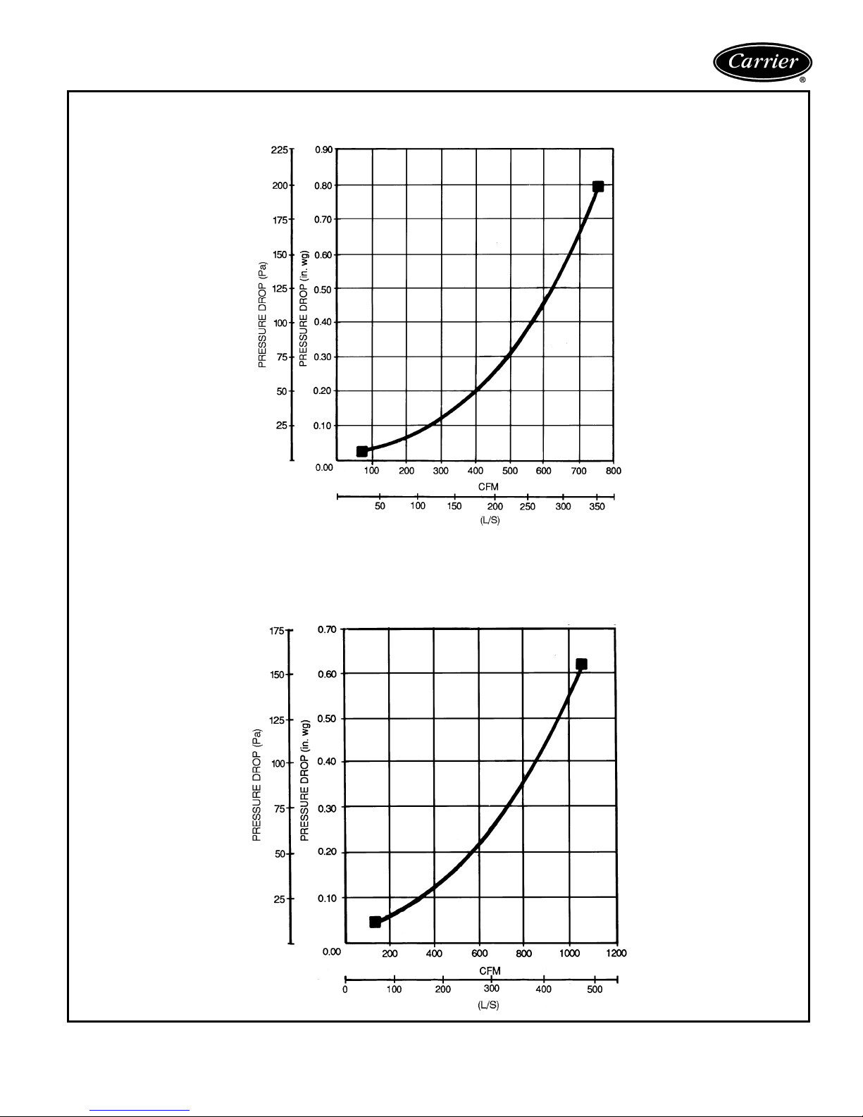
BAROMETRIC RELIEF DAMPER CHARACTERISTICS — 50TFF007
DURABLADE ECONOMIZER
BAROMETRIC RELIEF DAMPER CHARACTERISTICS — 50TFF008-014
DURABLADE ECONOMIZER
31
Page 32
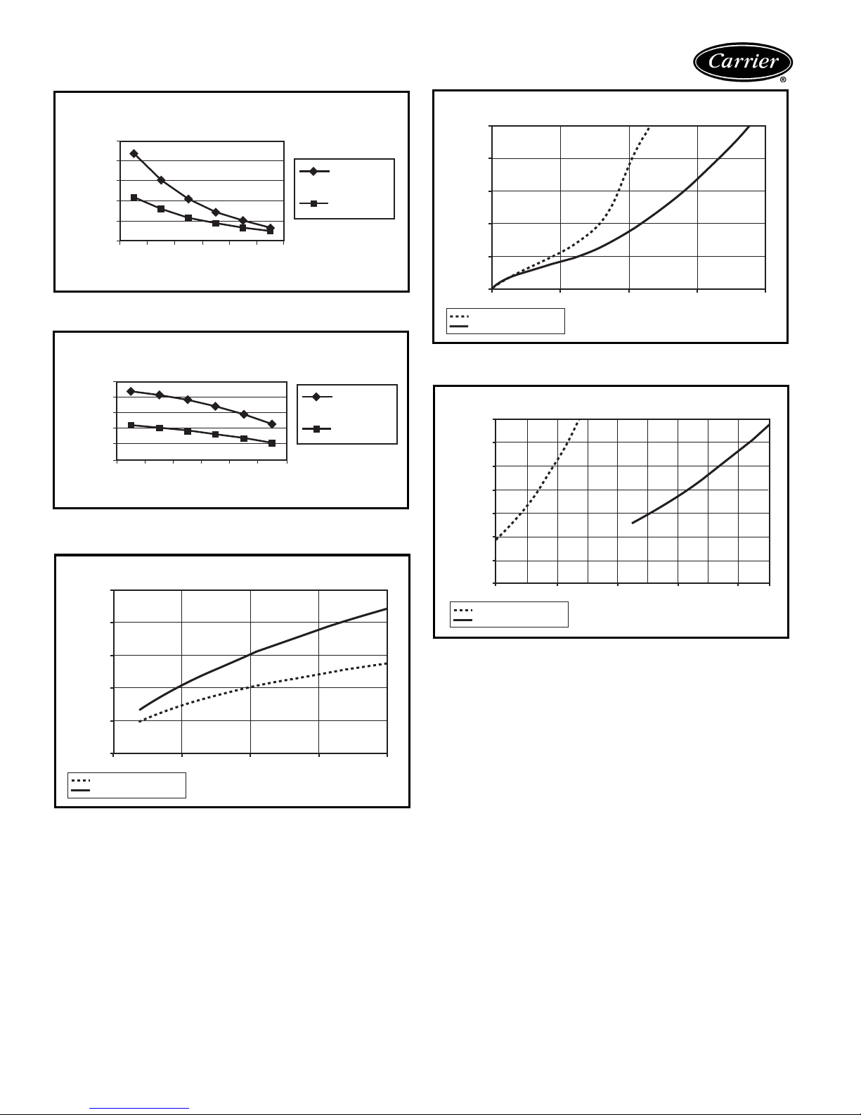
Performance data (cont)
ECONOMI$ER POWER EXHAUST PERFORMANCE
(50TFF007)
2500
FLOW (cfm)
2000
1500
1000
500
0
0.1
0
0.2
STATIC PRESSURE (in. wg)
0.3
0.4
0.5
2 FANS
OPERATING
1FAN
OPERATING
ECONOMI$ER POWER EXHAUST PERFORMANCE
(50TFF008-014)
FLOW (cfm)
5000
4000
3000
2000
1000
0
0.1
0
0.2
STATIC PRESSURE (in. wg)
0.3
0.4
0.5
2 FANS
OPERATING
1FAN
OPERATING
ECONOMI$ER OUTDOOR-AIR LEAKAGE
50
40
ECONOMI$ER BAROMETRIC FLOW
0.25
0.20
0.15
0.10
0.05
STATIC PRESSURE (in. wg)
0.00
0
SIZE 007
SIZES 008-014
500
1000
FLOW (CFM)
1500 2000
ECONOMI$ER RETURN-AIR PRESSURE DROP
0.35
0.30
0.25
0.20
0.15
0.10
STATIC PRESSURE (in. wg)
0.05
0.00
1200
SIZE 007
SIZES 008-014
2000
2800
FLOW (CFM)
3600 4400
30
20
FLOW (CFM)
10
0
0
SIZE 007
SIZES 008-014
0.25
STATIC PRESSURE (in. wg)
0.5
0.75 1
32
Page 33
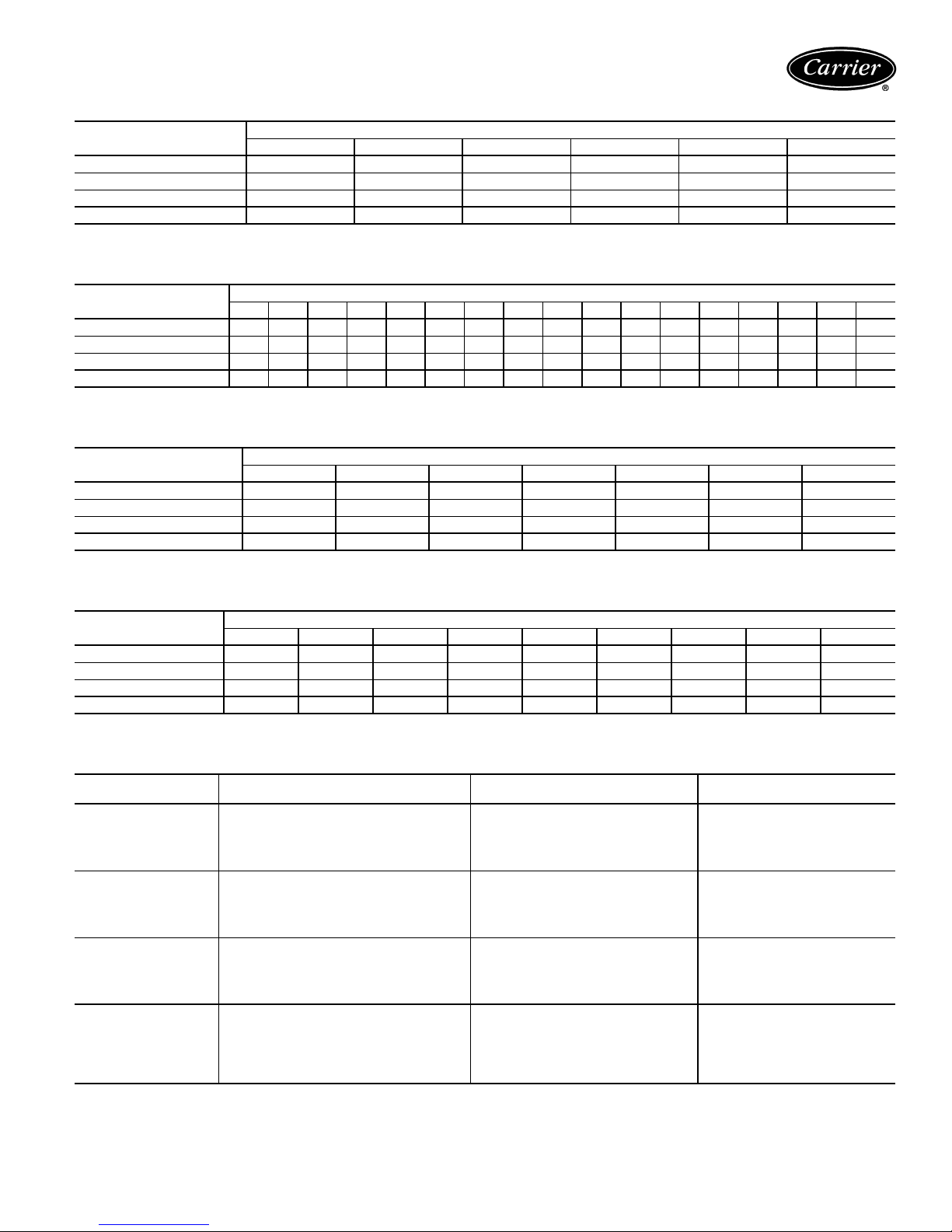
ACCESSORY/FIOP STATIC PRESSURE DROP (Pa) — 50TFF007
COMPONENT
1 Heater Module 20 22 25 27 30 32
2 Heater Modules 41 42 42 43 44 45
Durablade Economizer 12 12 12 12 12 12
EconoMi$er 32 40 50 63 77 —
700 800 900 1000 1100 1200
L/s
ACCESSORY/FIOP STATIC PRESSURE DROP (Pa) — 50TFF008-014
COMPONENT
1 Heater Module 1 2 4 6 8 10 12 14 16 18 19 21 23 25 27 29 31
2 Heater Modules 5 7 9 10 12 15 17 20 22 25 27 29 32 34 37 39 40
Durablade Economizer 234 56789101112131415161718
EconoMi$er ——————31354150596775849097105
800 900 1000 1100 1200 1300 1400 1500 1600 1700 1800 1900 2000 2100 2200 2300 2400
L/s
ACCESSORY/FIOP STATIC PRESSURE DROP (in. wg) — 50TFF007
COMPONENT
1 Heater Module 0.09 0.09 0.10 0.11 0.11 0.12 0.13
2 Heater Modules 0.16 0.16 0.17 0.17 0.17 0.18 0.18
Durablade Economizer 0.05 0.05 0.05 0.05 0.05 0.05 0.05
EconoMi$er 0.13 0.15 0.19 0.24 0.29 0.35 —
1500 1600 1800 2000 2200 2400 2500
Cfm
ACCESSORY/FIOP STATIC PRESSURE DROP (in. wg) — 50TFF008-014
COMPONENT
1 Heater Module 0.01 0.02 0.03 0.05 0.07 0.08 0.10 0.12 0.14
2 Heater Modules 0.02 0.03 0.05 0.07 0.09 0.12 0.14 0.16 0.19
Durablade Economizer 0.02 0.02 0.02 0.03 0.04 0.05 0.06 0.07 0.08
EconoMi$er — — — 0.125 0.18 0.27 0.34 0.40 —
1900 2200 2500 3000 3500 4000 4500 5000 5500
Cfm
ELECTRIC HEATING CAPACITIES — 50TFF007-014
UNIT
50TFF
007 400-3-50
008 400-3-50
009 400-3-50
012,
014
UNIT ELECTRICAL
CHARACTERISTICS
400-3-50
ACCESSORY
kW
4.2 0921
8.0 0941
9.7 0951
16.0* 0941
17.7* 0941, 0951
9.7 1681
11.5 1631
19.3 1641
22.9 1651
29.0* 1681, 1641
9.7 1681
11.5 1631
19.3 1641
22.9 1651
29.0* 1681, 1641
9.7† 1681
11.5** 1631
19.3 1641
22.9 1651
29.0 1681, 1641
34.7* 1631, 1651
PA RT NO.
50DJ90–
*Two heater packages are required to provide kW indicated.
†Available on 012 size units only.
**Available on 014 size units only.
NOTE: The kW ratings shown above are at 400 v.
33
Page 34
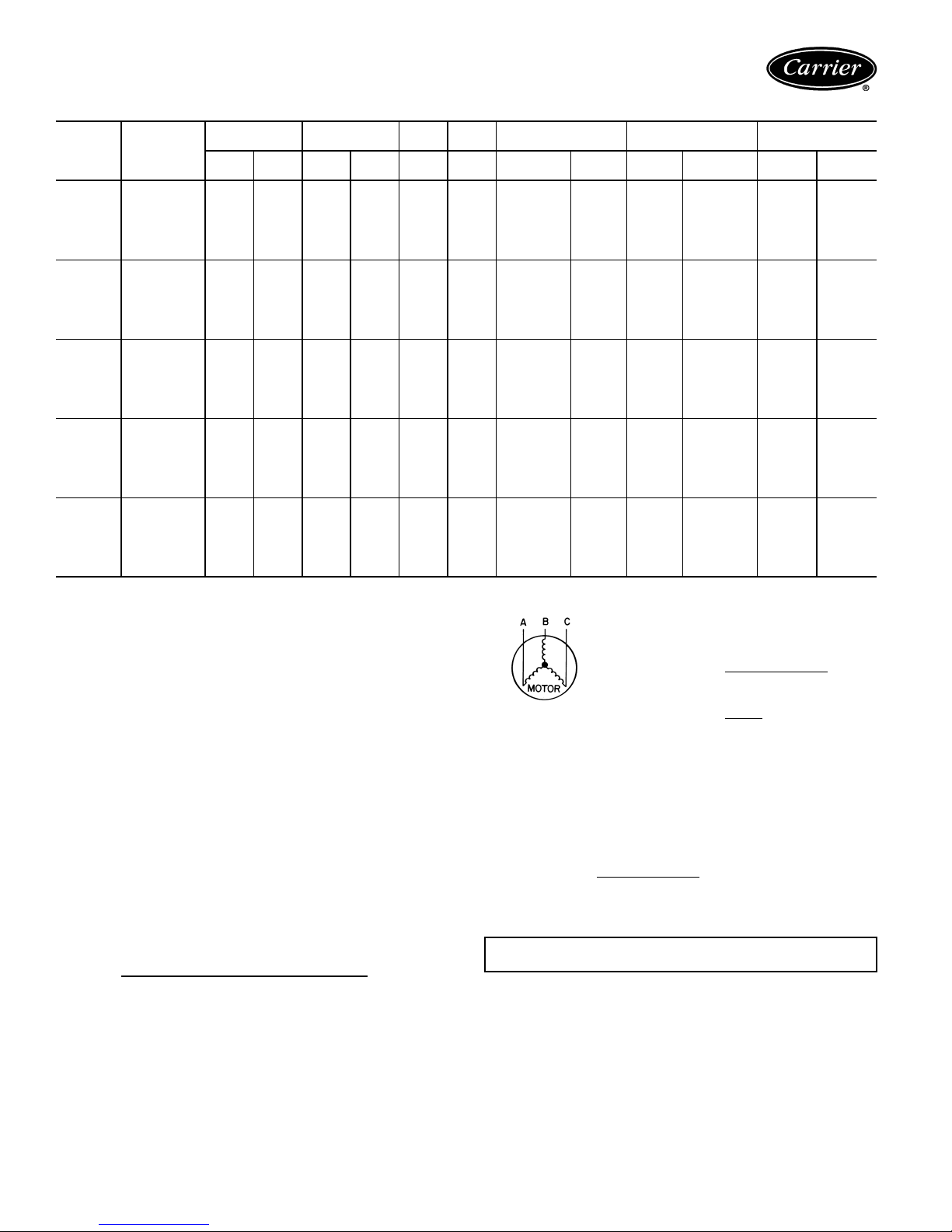
Electrical data
50TFF007-014
UNIT
50TFF
007
008
009
012
014
NOMINAL
VOLTA GE
(50 Hz)
400
(3 phase)
400
(3 phase)
400
(3 phase)
400
(3 phase)
400
(3 phase)
VOLTA GE
RANGE
Min Max RLA LRA FLAFLA
360 440 9.9 72.0 0.6 2.6
360 440 8.9 42.0 0.6 2.6
360 440 8.3 69.0 0.6 2.6
360 440 8.9 64.0 0.6 2.6
360 440 10.4 73.0 0.6 4.8
COMPR
(ea)
OFM
(ea)
IFM ELECTRIC HEAT* POWER SUPPLY
Nominal
kW†
— — 18.4 25 18
4.2 7.2 18.4 25 18
8.0 13.8 18.4 25 18
9.7 16.8 20.8 25 19
16.0 27.8 32.1 35 30
17.7 30.7 34.6 35 32
— — 23.8 30 25
9.7 13.9 23.8 30 25
11.5 16.5 23.9 25 25
19.3 27.8 38.1 40 35
22.9 33.1 44.6 45 41
29.0 41.8 55.5 60 51
— — 22.5 25 23
9.7 13.9 22.5 25 23
11.5 16.5 23.9 25 23
19.3 27.8 38.1 40 35
22.9 33.1 44.6 45 41
29.0 41.8 55.5 60 51
— — 23.8 30 25
9.7 16.5 23.9 30 25
19.3 27.8 38.1 40 35
22.9 33.1 44.6 45 41
29.0 41.8 55.5 60 51
34.7 50.1 65.9 70†† 61
— — 29.4 35 31
11.5 16.5 29.4 35 31
19.3 27.8 40.8 45 38
22.9 33.1 47.3 50 44
29.0 41.8 58.2 60 54
34.7 50.1 68.6 70†† 63
FLA MCA MOCP** FLA LRA
MINIMUM UNIT
DISCONNECT
109
103
162
152
192
LEGEND
FLA—Full Load Amps
HACR — Heating, Air Conditioning and Refrigeration
IFM — Indoor (Evaporator) Fan Motor
LRA — Locked Rotor Amps
MCA — Minimum Circuit Amps
MOCP — Maximum Overcurrent Protection
NEC — National Electrical Code (U.S.A.)
OFM — Outdoor (Condenser) Fan Motor
RLA—Rated Load Amps
*Heater capacity (kW) is based on heater voltage of 400 v. If power
distribution voltage to unit varies from rated heater voltage, heater
kW will vary accordingly.
†Heaters are field installed only.
**Fuse or HACR circuit breaker.
††Fusing in single point box provides the required branch circuit
protection.
NOTES:
1. In compliance with NEC requirements (U.S.A. Standard) for multimotor and combination load equipment (refer to NEC Articles 430 and
440), the overcurrent protective device for the unit shall be fuse or
HACR breaker.
2. Unbalanced 3-Phase Supply Voltage
Never operate a motor where a phase imbalance in supply voltage is
greater than 2%.
of voltage imbalance.
% Voltage imbalance
=100x
Use the following formula to determine the percent
max voltage deviation from average voltage
average voltage
EXAMPLE: Supply voltage is 400-3-50.
AB = 393 v
BC = 403 v
AC = 396 v
Average Voltage =
Determine maximum deviation from average voltage:
(AB) 397 – 393 = 4 v
(BC) 403 – 397 = 6 v
(AC) 397 – 396 = 1 v
Maximum deviation is 6 v.
Determine percent voltage imbalance.
Average Voltage =
This amount of phase imbalance is satisfactory as it is below the maximum allowable 2%.
IMPORTANT: If the supply voltage phase imbalance is more than
2%, contact your local electric utility company immediately.
393 + 403 + 396
3
393 + 403 + 396
3
1192
=
3
= 397
34
Page 35
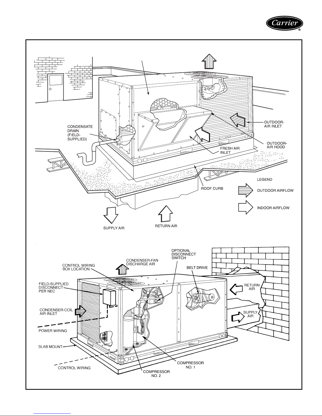
Typical piping and wiring — 50TFF007-014
(sizes 008-014 shown)
VERTICAL DISCHARGE DUCTING
TOOL-LESS FILTER
ACCESS DOOR
CONDENSER-FAN
DISCHARGE AIR
HORIZONTAL DISCHARGE DUCTING
LEGEND
NEC — National Electrical Code (U.S.A. Standard)
35
Page 36
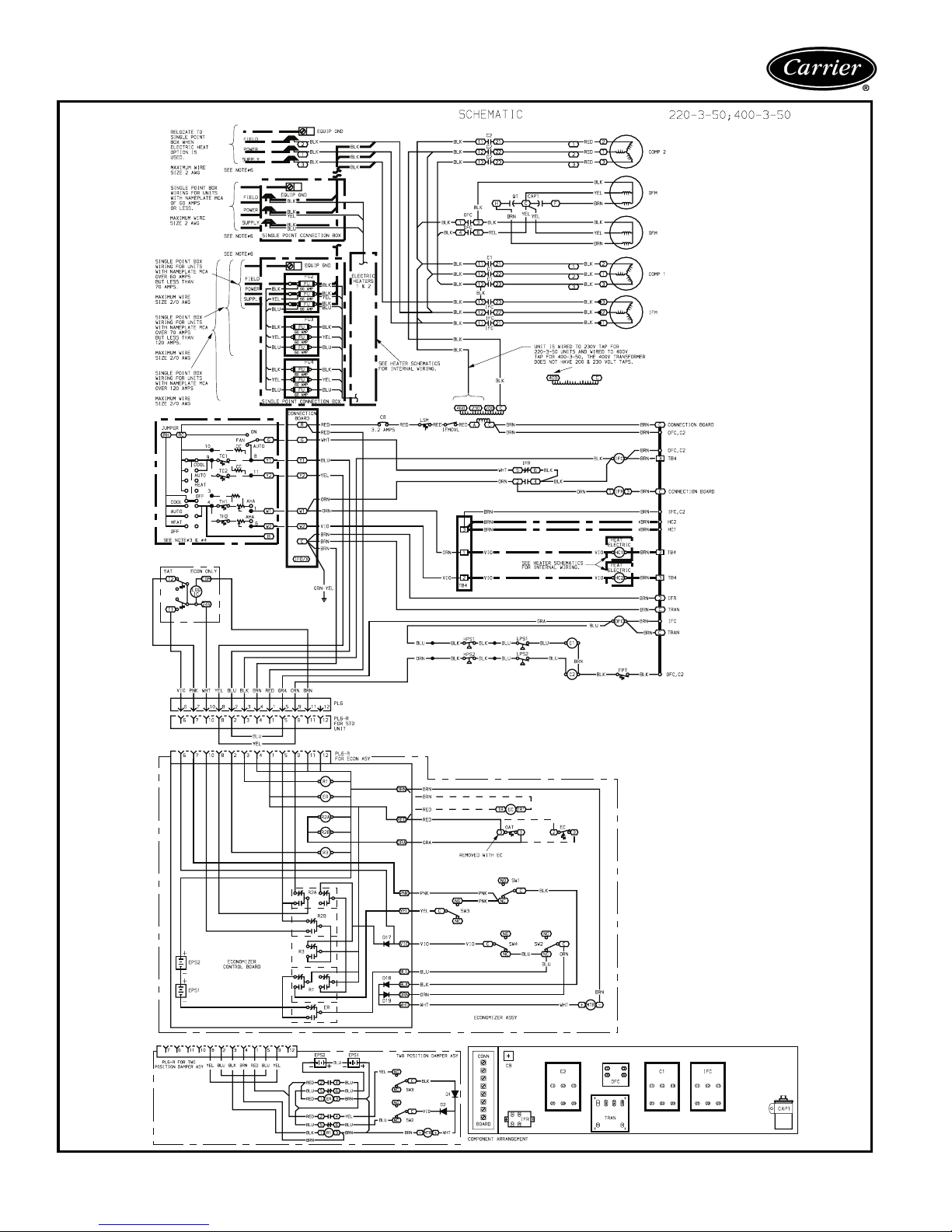
Typical wiring schematic (50TFF008-014 shown)
36
Page 37
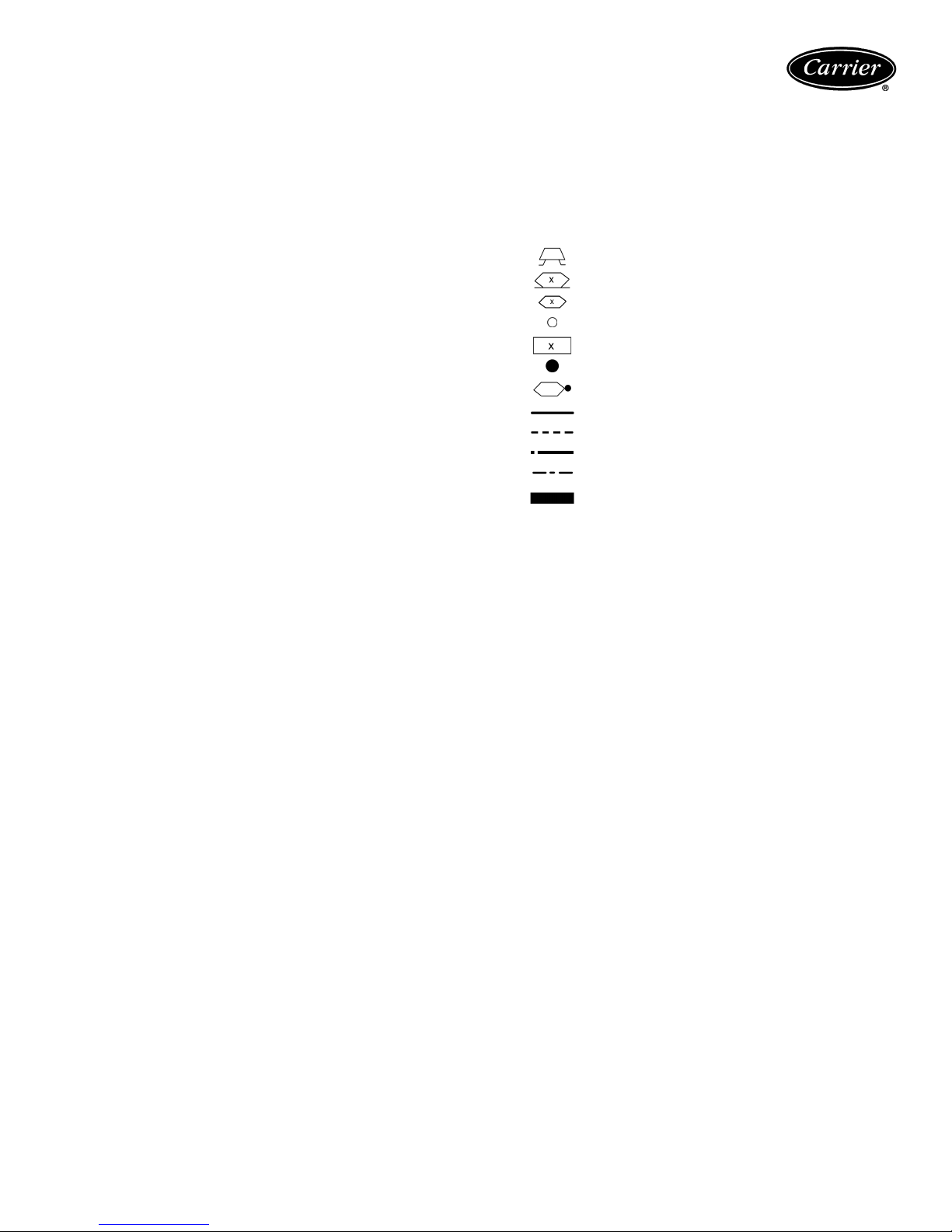
LEGEND
AHA — Adjustable Heat Anticipator
AWG — American Wire Gage
C—Contactor, Compressor
CAP — Capacitor
CB — Circuit Breaker
CC — Cooling Compensator
COMP — Compressor Motor
D — Diode
EC — Enthalpy Control
ECON — Economizer
EPS — Emergency Power Supply
EQUIP — Equipment
ER — Economizer Relay
FPT — Freeze-Up Protection Thermostat
FU — Fuse
GND — Ground
HC — Heater Contactor (Strip Heat)
HPS — High-Pressure Switch
IFC — Indoor-Fan Contactor
IFM — Indoor-Fan Motor
IFMOVL— Indoor-Fan Motor Overload
IFR — Indoor-Fan Relay
LPS — Low-Pressure Switch
LSM — Limit Switch (Manual Reset)
MTR — Motor
OAT — Outdoor-Air Thermostat
OFC — Outdoor-Fan Contactor
OFM — Outdoor-Fan Motor
P—Plug
PL — Plug Assembly
QT—Quadruple Terminal
R—Relay
SAT — Supply-Air Thermostat
SEN — Sensor
SW1—Switch Fully Open
SW2 — Switch Fully Closed
SW3 — Switch Min Vent Position
SW4—Switch Max Vent Position
TB — Terminal Block
TC — Thermostat-Cooling
TH — Thermostat-Heating
TRAN — Transformer
Field Splice
Marked Wire
Terminal (Marked)
Terminal (Unmarked)
Terminal Block
Splice
Splice (Marked)
Factory Wiring
Field Control Wiring
Field Power Wiring
Accessory or Optional Wiring
To indicate common potential only.
Not to represent wiring.
NOTES
1. If any of the original wire furnished must be replaced, it must be replaced with type 90 C
wire or its equivalent.
2. Three-phase motors are protected under primary single-phasing conditions.
3. Thermostat:
HH07AT170, 172, 174 and P272-2783
Subbase:
HH93AZ176, 178 and P272-1882, 1883
4. Set heat anticipator at 1 amp.
5. Use copper conductors only.
6. Use copper, copper-clad aluminum or aluminum conductors.
37
Page 38

Controls
Operating sequence
Cooling, units without economizer — When thermo-
stat calls for cooling, terminals G and Y1 are energized.
The indoor (evaporator) fan contactor (IFC), and compressor contactor no. 1 (C1) are energized and evaporator-fan
motor, compressor no. 1 and condenser fans start. The
liquid line solenoid valve for compressor no. 1 is deenergized to open. The condenser-fan motor runs continuously
while unit is cooling. On 50TFF008-014 units, if the thermostat calls for a second stage of cooling by energizing Y2,
compressor contactor no. 2 (C2) is energized and compressor no. 2 starts.
Heating, units without economizer (If Accessory
Heater is Installed) — Upon a call for heating through
terminal W1, IFC and heater contactor no. 1 (HC1) are
energized. On units equipped for 2 stages of heat, when
additional heat is needed, HC2 is energized through W2.
Cooling, units with Durablade economizer — When
the outdoor-air temperature is above the outdoor-air thermostat (OAT) setting and the room thermostat calls for
cooling, compressor contactor no. 1 is energized to start
compressor no. 1 and the condenser-fan motor. The
evaporator-fan motor is energized and the economizer
damper moves to the minimum position. Upon a further
call for cooling, compressor contactor no. 2 will be energized (50TFF008-014), starting compressor no. 2. After
the thermostat is satisfied, the damper moves to the fully
closed position.
When the outdoor-air temperature is below the OAT setting and the thermostat calls for cooling, the economizer
dampers move to the minimum position. If the supply-air
temperature is above 13.9 C (57 F), the damper continues
to open until it reaches the fully open position or until the
supply-air temperature drops below 13.9 C (57 F).
When the supply-air temperature falls to between
13.9 C (57 F) and 11.1 C (52 F), the damper will remain at
an intermediate open position. If the supply-air temperature falls below 11.1 C (52 F), the damper will modulate
closed until it reaches the minimum position or until the
supply-air temperature is above 11.1 C (52 F). When the
thermostat is satisfied, the damper will move to the fully
closed position.
If the outdoor air alone cannot satisfy the cooling
requirements of the conditioned space, economizer cooling is integrated with mechanical cooling, providing
second-stage cooling. Compressor no. 1 and the
condenser fan will be energized and the position of the
economizer damper will be determined by the supply-air
temperature. Compressor no. 2 (50TFF008-014) is locked
out.
When the second stage of cooling is satisfied, the compressor and condenser-fan motor will be deenergized.
The damper position will be determined by the supply-air
temperature.
When the first stage of cooling is satisfied, the damper
will move to fully closed position.
Cooling, units with EconoMi$er (50TFF007) —
When the outdoor-air temperature (OAT) is above the
ECON SP set point and the room thermostat calls for
Stage 1 cooling (R to G + Y1), the indoor (evaporator) fan
motor (IFM) is energized and the EconoMi$er damper
modulates to minimum position. The compressor contactor is energized to start the compressor and outdoor (condenser) fan motor (OFM). After the thermostat is satisfied,
the damper modulates to the fully closed position when the
IFM is deenergized.
When the OAT is below the ECON SP setting and the
room thermostat calls for Stage 1 cooling (R to G + Y1),
the EconoMi$er modulates to the minimum position when
the IFM is energized. The EconoMi$er provides Stage 1 of
cooling by modulating the return and outdoor-air dampers
to maintain a 12.8 C (55 F) supply air set point. If the
supply-air temperature (SAT) is greater than 13.9 C (57 F),
the EconoMi$er modulates open, allowing a greater
amount of outdoor air to enter the unit. If the SAT drops
below 11.7 C (53 F), the outdoor air damper modulates
closed to reduce the amount of outdoor air. When the SAT
is between 11.1 and 13.9 C (53 and 57 F), the
EconoMi$er maintains its position.
If outdoor-air alone cannot satisfy the cooling requirements of the conditioned space, and the OAT is above the
MECH CLG LOCKOUT set point, the EconoMi$er integrates free cooling with mechanical cooling. This is accomplished by the strategies below.
NOTE: Compressor has a 2-minute Minimum On, Minimum Off, and Interstage delay timer.
1. If Y1 is energized, and the room thermostat calls for
Y2 (2-stage thermostat), the compressor and OFM
are energized. The EconoMi$er damper is maintained at its current position.
2. If Y1 is energized for more than 20 minutes, and Y2
is not energized (whether or not a 2-stage thermostat
is used), the compressor and OFM are energized.
The EconoMi$er damper is maintained at its current
position.
3. If Y1 is energized, and the compressor is already
energized (see Step 2) and the room thermostat calls
for Y2, the compressor continues to operate.
4. If compressor is energized and the thermostat is satisfied, the compressor, the OFM, and IFM are deenergized and the EconoMi$er modulates closed.
When the OAT is below the MECH CLG LOCKOUT set
point, the compressors remain off.
Cooling, units with EconoMi$er (50TFF008-014)
— When the outdoor-air temperature (OAT) is above the
ECON SP set point and the room thermostat calls for
Stage 1 cooling (R to G + Y1), the indoor (evaporator) fan
motor (IFM) is energized and the EconoMi$er damper
modulates to minimum position. The compressor contactor is energized to start the compressor and outdoor (condenser) fan motor (OFM). After the thermostat is satisfied,
the damper modulates to the fully closed position when the
IFM is deenergized.
When the OAT is below the ECON SP setting and the
room thermostat calls for Stage 1 cooling (R to G + Y1),
the EconoMi$er modulates to the minimum position when
the IFM is energized. The EconoMi$er provides Stage 1 of
cooling by modulating the return and outdoor-air dampers
to maintain a (12.8 C) 55 F supply air set point. If the supply-air temperature (SAT) is greater than 13.9 C (57 F), the
EconoMi$er modulates open, allowing a greater amount of
outdoor air to enter the unit. If the SAT drops below
11.7 C (53 F), the outdoor air damper modulates closed to
reduce the amount of outdoor air. When the SAT is between 11.7 and 13.9 C (53 and 57 F), the EconoMi$er
maintains its position.
38
Page 39
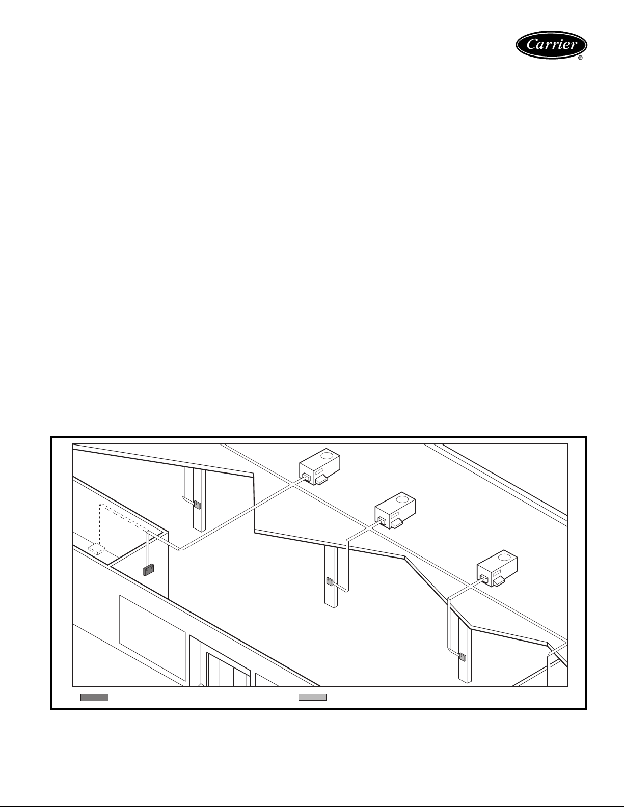
If outdoor-air alone cannot satisfy the cooling requirements of the conditioned space, and the OAT is above the
MECH CLG LOCKOUT set point, the EconoMi$er integrates free cooling with mechanical cooling. This is accomplished by the strategies below.
NOTE: Compressors have a 2-minute Minimum On, Minimum Off, and Interstage delay timer.
1. If Y1 is energized, and the room thermostat calls for
Y2 (2-stage thermostat), compressor no. 1 and OFM
are energized. The EconoMi$er damper is maintained at its current position.
2. If Y1 is energized for more than 20 minutes, and Y2
is not energized (whether or not a 2-stage thermostat
is used), compressor no. 1 and OFM are energized.
The EconoMi$er damper is maintained at its current
position.
3. If Y1 is energized, and compressor no. 1 is already
energized (see Step 2) and the room thermostat calls
for Y2, compressor no. 1 continues to operate. If Y2
remains energized for more than 20 minutes, compressor no. 2 is energized.
NOTE: Compressor no. 2 cannot be energized unless
there is a signal for Y2 from the space thermostat.
4. If compressor no. 2 is energized, and the Y2 signal
from the thermostat is satisfied, compressor no. 1
and 2 are deenergized. Reasserting Y2 will start compressor no. 1 and (after a 20-minute interstage delay)
compressor 2.
5. If compressor no. 1 is energized and the thermostat is
satisfied, compressor no. 1, the OFM, and IFM are
deenergized and the EconoMi$er modulates closed.
When the OAT is below the MECH CLG LOCKOUT set
point, the compressors remain off.
Heating, units with economizer (If Accessory
Heater is Installed) — When the room thermostat calls
for heat through terminal W1, the evaporator-fan contactor and heater contactor no. 1 are energized. On units
equipped for 2 stages of heat, when additional heat is
needed, heater contactor no. 2 is energized through W2.
The economizer damper moves to the minimum position
during heating. When the thermostat is satisfied, the
damper moves to the fully closed position.
TEMP systems
A TEMP System is a network of communicating Carrier
TEMP System Thermostats and rooftop, factory-mounted
Apollo direct digital controls, each serving its own zone
and heating/cooling unit. Networking allows your building
manager to easily access each of your systems from a single location...whether they are in the same building or
located throughout town.
The TEMP System’s inherently flexible, modular base
design supports the exact number of independent, single
zone systems you require...no more, no less, no compromises.
Ideal for department stores, small office buildings, fast
food chains, schools and hotels, a TEMP System is a
cost-effective way to maintain comfortable building
environments.
TEMP SYSTEM THERMOSTAT (WITH TIMECLOCK) TEMP SYSTEM THERMOSTAT (WITHOUT TIMECLOCK)
39
Page 40
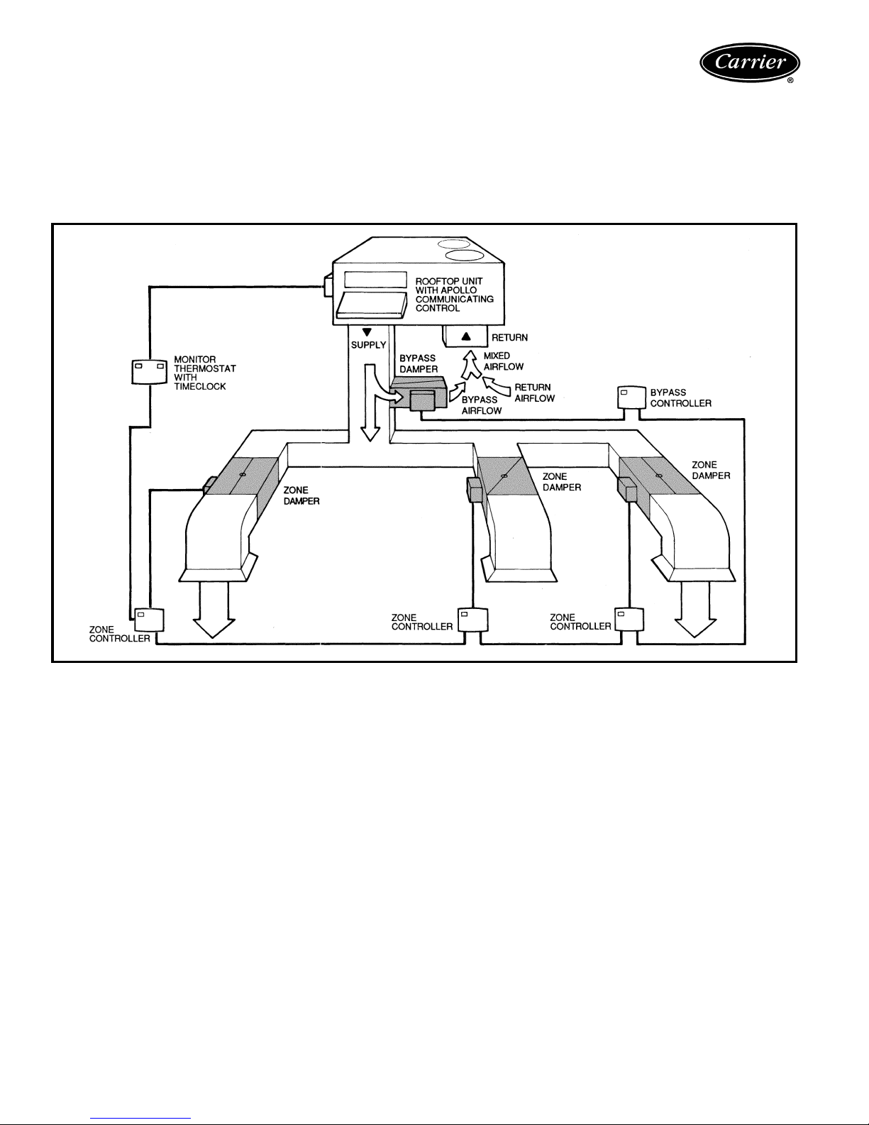
Controls (cont)
Variab le Vo lum e/ Variabl e Te mpera tur e
(VVT®) Systems
VVT Systems are dedicated to total building comfort. Carrier thermostats, zone dampers, and HVAC equipment
with factory-mounted direct digital controls continually
monitor and adjust their operation to ensure uninterrupted
and personalized comfort for all occupants.
Through the use of communicating electronic controls,
VVT Systems are able to provide the comfort of a multiple
zone system while using the installation, operating and
maintenance economics of single zone equipment...virtually putting an end to the cost vs comfort compromise.
40
Page 41

Application data
Outdoor installation — Units approved for outdoor
installation only.
Ductwork — Secure vertical discharge ductwork to roof
curb. For horizontal discharge applications, either attach
ductwork to unit, or use field-supplied flanges attached to
the horizontal discharge openings and attach all ductwork
to flanges.
Horizontal discharge — To convert from vertical discharge to horizontal discharge:
1. Remove economizer or two-position damper to gain
access to return duct opening.
2. Move the horizontal-discharge duct opening covers to
the vertical discharge openings.
3. Rotate economizer or two-position damper
90 degrees.
4. Rotate the barometric relief damper 90 degrees.
5. Install block-off plate over the opening on the access
panel.
Thru-the-curb service connections — Roof curb connections allow field power wires and control wires to enter
through the roof curb opening.
Thru-the-bottom service connections — Power connections made through the bottom of the unit must utilize
an accessory Carrier roof curb and accessory thru-the-bottom power connection accessory kit.
Thermostat — Use of 2-stage heating and cooling thermostat is recommended for all units. A 2-stage cooling
thermostat is required on units with accessory economizer
to provide integrated cooling.
Heating-to-cooling changeover — All units are automatic changeover from heating to cooling when automatic
changeover thermostat and subbase are used.
Airflow — Units are draw-thru on cooling and blow-thru
on heating.
Maximum airflow — To minimize the possibility of condensate blow-off from evaporator, airflow through units
should not exceed 67 L/s per kW (500 cfm/ton).
Minimum airflow — For cooling minimum airflow is
40 L/s per kW (300 cfm/ton). For 50TFF007-014 units
with electric heating, required minimum L/s (cfm) is 849
(1800) for 50TFF007; 1062 (2250) for 50TFF008; 1203
(2550) for 50TFF009; and 1416 (3000) for 50TFF012
and 014.
Minimum ambient cooling operating temperature
— The minimum temperature for standard units is –4 C
(25 F). With accessory Motormaster® II control, units can
operate at outdoor temperatures down to –17.8 C (0° F).
Internal unit design — Due to Carrier’s internal unit
design (draw-thru over the motor), air path, and specially
designed motors, the full kW horsepower (maximum continuous bkW and bhp) listed in the Physical Data tables and
the notes following each Fan Performance table can be utilized with confidence.
Using Carrier motors with the values listed in the Physical and Fan Performance Data tables will not result in nuisance tripping or premature motor failure. The unit
warranty will not be affected.
Apollo direct digital controls — The Apollo direct digital controls must be used with either a Carrier master or
monitor thermostat.
41
Page 42

Guide specifications
Packaged Rooftop Cooling Unit with
Electric Heat Option — Constant Volume
Application
HVAC Guide Specifications
Size Range: 17.6 to 35.9 kW (5.0 to 10.2 Tons)
Carrier Model Number: 50TFF
Part 1 — General
1.01 SYSTEM DESCRIPTION
Outdoor rooftop- or slab-mounted, electrically con-
trolled cooling unit with optional heat utilizing a hermetic compressor for cooling duty and electric
resistance coils for heating duty. Unit shall discharge
supply air vertically or horizontally as shown on contract drawings.
1.02 QUALITY ASSURANCE
A. Unit shall be rated in accordance with ARI Standards
210/240 or 360 and 270 (U.S.A.).
B. Unit shall be designed to conform to ASHRAE 15,
latest revision, and in accordance with UL 1995.
(U.S.A. Standards).
C. Roof curb shall be designed to conform to NRCA
Standards (U.S.A.).
D. Insulation and adhesive shall meet NFPA 90A
requirements (U.S.A. Standard) for flame spread and
smoke generation.
E. Unit casing shall be capable of withstanding Federal
test method (U.S.A. Standard) Standard ASTM B117
500-hour salt spray test.
F. Units shall be designed in accordance with
ISO 9001:2000, and shall be manufactured in a
facility registered to ISO 9001:2000.
1.03 DELIVERY, STORAGE, AND HANDLING
Unit(s) shall be stored and handled per manufacturer’s
recommendations.
Part 2 — Products
2.01 EQUIPMENT (STANDARD)
A. General:
Factory-assembled, single-piece cooling unit with
optional heat. Contained within the unit enclosure
shall be all factory wiring, piping, controls, refrigerant
charge (R-22), and special features required prior to
field start-up.
B. Unit Cabinet:
Nominal Cooling
1. Unit cabinet shall be constructed of galvanized
steel, bonderized and coated with a baked
enamel finish on all externally exposed surfaces.
2. Evaporator fan cabinet interior shall be insulated
with a minimum 13 mm (
sity neoprene coated, flexible fiberglass insulation coated on the air side.
3. Cabinet panels shall be easily removable for
servicing.
4. Holes shall be provided in the base rails for rigging shackles to facilitate overhead rigging, and
forklift slots shall be provided to facilitate
maneuvering.
5. Unit shall have a factory-installed, sloped condensate drain pan made of a non-corrosive
1
/2-in.) thick 1 lb den-
material, providing a minimum 19 mm (
connection with both vertical and horizontal
drains and shall comply with ASHRAE 62.
6. Unit shall have factory-installed filter access
panel to provide filter access with tool-less
removal.
7. Unit shall have standard thru-the-bottom power
connection capability.
C. Fans:
1. Indoor blower (evaporator fan) shall be beltdriven, double inlet, forward-curved centrifugal
type. Belt drive shall include an adjustable-pitch
motor pulley.
2. Indoor blower (evaporator-fan) shall be made
from steel with a corrosion-resistant finish and
shall be dynamically balanced.
3. Bearings shall be of the sealed, permanently
lubricated, ball-bearing type for longer life and
lower maintenance.
4. Condenser fan shall be of the direct-driven propeller type and shall discharge air vertically.
5. Condenser fan shall have aluminum blades riveted to corrosion-resistant steel spiders and shall
be dynamically balanced.
D. Compressor(s):
1. Reciprocating or scroll type fully hermetic type,
internally protected.
2. Factory rubber-mounted and internally spring
mounted for vibration isolation.
3. On independent mounting circuits (008-014).
E. Coils:
1. Condenser coils shall have aluminum plate fins
mechanically bonded to enhanced copper tubes
with all joints brazed.
2. Tube sheet openings shall be belled to prevent
tube wear.
3. Evaporator coil shall be of the full face active
design.
F. Refrigerant Components:
Refrigerant circuit components shall include:
1. Refrigerant feed system.
2. Refrigerant filter drier.
3. Service gage connections on suction, discharge,
and liquid line.
G. Filter Section:
1. Standard filter section shall consist of factoryinstalled low-velocity, throwaway 51 mm (2-in.)
thick fiberglass filters of commercially available
sizes.
2. Filter face velocity shall not exceed 1.64 m/s
(320 fpm) at nominal airflows.
3. Filter section shall use only one size filter.
4. Filters shall be accessible through an access
panel with ‘‘no-tool’’ removal.
H. Controls and Safeties:
1. Unit Controls:
Unit shall be complete with self-contained low-
voltage control circuit.
3
/4-in.)
42
Page 43

2. Standard Safeties:
a. Unit shall incorporate compressor over-
temperature and overcurrent safety devices to
shut off compressor.
b. Heating section shall be provided with the fol-
lowing minimum protections:
1) High-temperature limit switches.
2) Overcurrent protection.
3. Refrigerant Controls:
Shall contain high-pressure, loss-of-charge/
low-pressure, and freeze protection
switches.
I. Operating Characteristics:
1. Unit shall be capable of starting and running at
46.1 C (115 F) ambient outdoor temperature,
meeting maximum load criteria of ARI Standard
210/240 or 360 (U.S.A. Standard) at ± 10%
voltage.
2. Compressor with standard controls shall be
capable of operation down to –4 C (25 F) ambient outdoor temperature.
J. Electrical Requirements:
All unit power wiring shall enter unit cabinet at a single factory-predrilled location.
K. Motors:
1. Compressor motors shall be cooled by refrigerant passing through motor windings and shall
have line break thermal and current overload
protection.
2. Indoor blower (evaporator-fan) motor shall have
permanently lubricated bearings and inherent
automatic-reset thermal overload protection.
3. Totally enclosed condenser-fan motor shall have
permanently lubricated bearings, and inherent
automatic-reset thermal overload protection.
L. Special Features:
Certain features are not applicable when the features
designated by * are specified. For assistance in
amending the specifications, your local Carrier Sales
Office should be contacted.
* 1. Direct Digital Controls:
a. Shall be available as a factory-installed option.
b. Shall actively monitor all modes of operation,
as well as evaporator-fan status, filter status,
indoor-air quality, supply-air temperature, and
outdoor-air temperature.
c. Shall work with Carrier TEMP and VVT®
systems.
d. Shall have built-in diagnostics for thermostat
commands for both staged heating and cooling, evaporator-fan operation, and economizer operation.
e. Shall be equipped with a 5-minute time delay
between modes of operation.
2. Roof Curbs: (Horizontal and Vertical)
a. Formed galvanized steel with wood nailer
strip and capable of supporting entire unit
weight.
b. Allows for installing and securing ductwork to
curb prior to mounting unit on the curb.
* 3. Integrated Economizer:
a. Integrated integral-modulating type capable
of simultaneous economizer and compressor
operation.
b. Includes all hardware and controls to provide
cooling with outdoor air.
c. Equipped with low-leakage dampers not to
exceed 3% leakage, at 249 Pa (1 in. wg) pressure differential (Durablade economizer).
d. Capable of introducing up to 100% outdoor
air in both minimum and fully open positions.
e. Equipped with a gravity relief sliding plate
damper (Durablade economizer). Damper
shall close upon unit shutoff.
f. EconoMi$er shall be equipped with a baro-
metric relief damper with up to 100% of
return air (007) or 90% of return air (008-
014) relief. Durablade economizer is
equipped with 30% of return-air relief.
g. Designed to close damper during loss-of-
power situations with emergency power supply (Durablade economizer) or spring return
built into motor (EconoMi$er).
h. Dry bulb outdoor-air thermostat (Durablade
economizer) shall be provided as standard.
Enthalpy control shall be provided as an
option.
i. Durablade economizer is a guillotine-style
damper and EconoMi$er is a parallel-blade
design.
NOTE: EconoMi$er shall also be available
with field-installed power exhaust accessory.
* 4. Manual Outdoor-Air Damper:
Manual damper package shall consist of
damper, birdscreen, and rainhood which can be
preset to admit up to 50% outdoor air for yearround ventilation.
* 5. 100% Open Two-Position Damper:
a. Two-position damper package shall include
single blade damper and motor. Admits up to
100% outdoor air.
b. Damper shall close upon indoor (evaporator)
fan shutoff.
c. Designed to close damper during loss of
power situations.
d. Equipped with barometric relief damper.
* 6. 25% Open Two-Position Damper:
a. Two-position damper package shall include
single blade damper and motor. Admits up to
25% open outdoor air.
b. Damper shall close upon indoor (evaporator)
fan shutoff.
c. Designed to close damper during loss of
power situations.
d. Equipped with barometric relief damper.
* 7. Solid-State Enthalpy Control:
a. For use with Durablade economizer
package.
b. Capable of sensing outdoor-air enthalpy
content (temperature and humidity) and
43
Page 44
Guide specifications (cont)
controlling economizer cut-in point to have
minimum heat content air passing over the
evaporator coil for most efficient system
operation.
* 8. Differential Enthalpy Sensor:
a. For use with economizer only.
b. Capable of comparing enthalpy content
(temperature and humidity) of outdoor and
indoor air and controlling economizer cutin point at the most economical level.
* 9. Electric Resistance Heaters:
a. Open wire nichrome elements with all nec-
essary safety operating controls.
b. UL (U.S.A. Standard) listed and indicated
on basic unit informative plate.
c. Available in multiples to match heating
requirements.
*10. Low-Ambient Operation (Head Pressure
Control) Package:
Consists of solid-state control and condenser-
coil temperature sensor to operate at outdoor
ambient temperatures down to –17.8 C (0° F)
by condenser-fan cycling.
*11. Thermostat and Subbase:
Provides staged cooling and heating automatic (or manual) changeover, fan control,
and indicator light.
12. Thru-The-Bottom Service Connectors:
Kit shall provide connectors to permit electri-
cal connections to be brought to the unit
through the basepan.
*13. Electronic Programmable Thermostat:
Capable of using deluxe full-featured electronic thermostat. Shall use built-in compressor cycle delay control for both heating and
cooling duty. Capable of working with
Carrier direct digital controls.
14. Condenser Coil Hail Guard Assembly:
Hail guard shall protect against damage from
hail and flying debris.
15. Condenser Coil Grille:
The grille protects the condenser coil from
damage by large objects without increasing
unit clearances.
16. Compressor Cycle Delay:
Unit shall be prevented from restarting for a
minimum of 5 minutes after shutdown.
17. Salt Spray Protection Package (008-014):
Coil guard protects coil from corrosion in
coastal areas and in areas with high sulfur
emissions.
18. Fan/Filter Status Switch:
Provides status of indoor fan (ON/OFF) or
filter (CLEAN/DIRTY). Status shall be displayed over communication bus when used
with direct digital controls or with an indicator light at the thermostat.
19. Unit-Mounted Disconnect Switch:
Shall be factory-installed. Internally mounted,
non-fused switch provides unit power shutoff.
Shall be accessible from outside the unit.
20. Logo Kit:
Shall provide logo for field installation onto
outdoor coil grille.
21. EconoMi$er and Power Exhaust:
Package shall provide control of internal
building pressure. The system shall exhaust
up to 100% of return air.
22. Power Exhaust for Accessory EconoMi$er:
Power exhaust shall be used in conjunction
with EconoMi$er to provide the system with
the capability to exhaust up to 100% of
return air. The power exhaust is fieldinstalled accessory.
23. Outdoor-Air Enthalpy Sensor:
The outdoor-air enthlapy sensor shall be
used with the EconoMi$er device to provide
single enthalpy control. When used in conjunction with a return air enthalpy sensor,
the EconoMi$er device will provide different
enthalpy control. The sensor allows the
EconoMi$er controller to determine if outside air is suitable for free cooling.
24. Return-Air Enthalpy Sensor:
The return-air enthalpy sensor shall be used
with the EconoMi$er device. When used in
conjunction with an outdoor air enthalpy
sensor, the EconoMi$er device will provide
differential enthalpy control.
25. Return-Air Temperature Sensor:
The return-air temperature sensor shall be
used with the EconoMi$er device. When
used in conjunction with the standard
outdoor air temperature sensor, the
EconoMi$er device will provide differential
temperature control.
26. Indoor-Air Quality (CO
) Sensor:
2
a. Shall have the ability to provide demand
ventilation indoor-air quality (IAQ) control through the economizer with an IAQ
sensor.
b. The IAQ sensor shall be available in duct
mount, wall mount, and wall mount with
LED display. The set point shall have
adjustment capability.
Carrier Corporation • Syracuse, New York 13221 204 9-00
Manufacturer reserves the right to discontinue, or change at any time, specifications or designs without notice and without incurring obligations.
Book 1 4
Ta b 1 b 6 b
Book 1
New Page 44 Catalog No. 005-003 Printed in U.S.A. Form 50TFF-C1PD
Ta b O P2 b
Replaces: New
 Loading...