

Carrier 50TCM Series, 50TCMA07, 50TCMD08, 50TCMD12, 50TCMD09 Installation, Operation And Maintenance Manual
...Page 1

Installation, Operation and Maintenance
50TCM – 50Hz
Nominal Cooling Capacity 6 – 12.5 Tons
HFC R - 410A Refrigerant
Package Rooftop Units – 50Hz
Quality Assurance
Page 1
Certificate Reg. No:
04 100 950420
Subject to change without notice
Manufacturing point: Jeddah, Saudi Arabia
Nearest port of embarkation: Jeddah Islamic port
Product classification: Commercial
The 50TCM units are single side discharge rooftop cooling unit utilizing electric heat as an option. Units are prewired, pre-charged with R-410A refrigerant, and tested at the factory. These units can be placed on the side of a
building or can be placed on a roof without roof curbs. Each unit is designed to occupy a minimal space. Piping and
drain connections are readily accessible.
Contact your local Carrier representative for additional reference materials.
Page 2

Table of Contents
Page 2
1.0 – SAFETY CONSIDERATIONS ............................................................................................................................. 3
1.1 – General ................................................................................................................................................... 3
1.2 – Installation Safety Considerations .......................................................................................................... 3
1.3 – Warranty ................................................................................................................................................. 3
Unit Physical Data ...................................................................................................................................................... 5
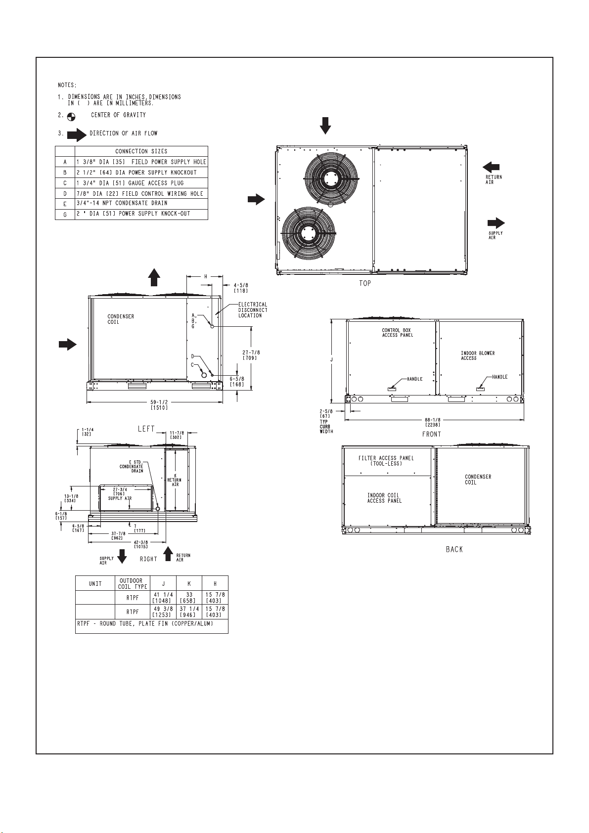
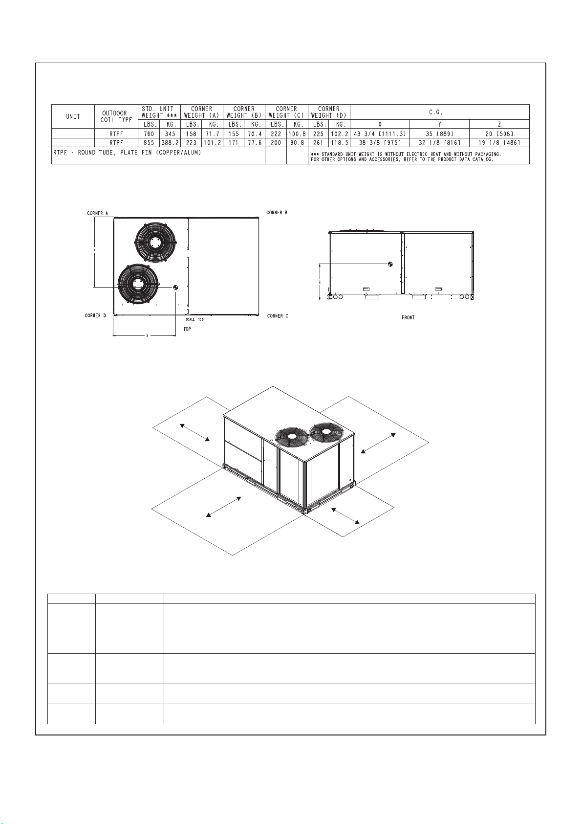
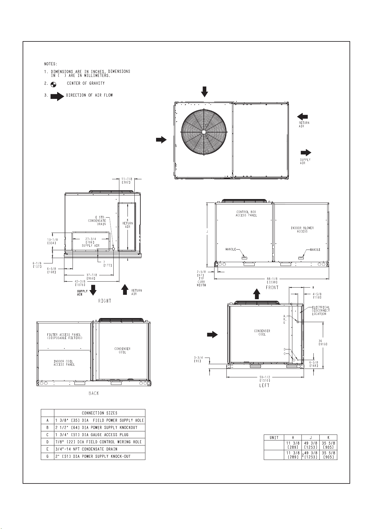
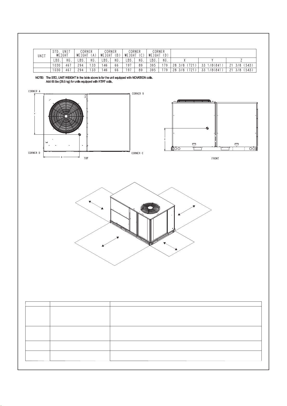
Unit Dimensional Drawing ......................................................................................................................................... 6
2.0 – INSTALLAT ION ................................................................................................................................................ 12
2.1 – Jobsite Survey ...................................................................................................................................... 12
2.2 – Plan for Unit Location ........................................................................................................................... 12
2.3 – Inspect Unit ........................................................................................................................................... 12
2.4 – Rig and Place Unit ................................................................................................................................ 12
2.5 – Positioning and Clearance .................................................................................................................... 13
2.6 – Field Fabricate Ductwork ...................................................................................................................... 14
2.7 – Make Unit Duct Connections ................................................................................................................ 14
2.8 – Trap Condensate Drain ........................................................................................................................ 14
2.9 – Make Electrical Connections ................................................................................................................ 14
3.0 – START–UP INSTRUCTIONS ............................................................................................................................ 17
3.1 – Unit Preparation .................................................................................................................................... 17
3.2 – Internal Wiring ....................................................................................................................................... 17
3.3 – Compressor Mounting .......................................................................................................................... 17
3.4 – Refrigerant Service Ports ..................................................................................................................... 17
3.5 – Compressor Rotation ............................................................................................................................ 17
3.6 – Evaporator Fan ..................................................................................................................................... 17
3.7 – Condenser Fans and Motors ................................................................................................................ 17
3.8 – Return – Air Filters ................................................................................................................................ 17
3.9 – B
4.0 – SERVICE ........................................................................................................................................................... 18
4.1 – Cleaning ................................................................................................................................................ 18
4.2 – Lubrication ............................................................................................................................................ 18
4.3 – Evaporator Fan Performance Adjustment ............................................................................................ 19
4.4 – Evaporator Fan Service and Replacement........................................................................................... 19
4.5 – Belt Tension Adjustment ....................................................................................................................... 20
4.6 – Condenser – Fan Adjustment ............................................................................................................... 20
4.7 – Refrigerant Charge ............................................................................................................................... 20
4.8 – Protective Devices ................................................................................................................................ 21
4.9 – Control Circuit, 24 – V........................................................................................................................... 21
5.0 – REPLACEMENT PARTS .................................................................................................................................. 21
Electrical Data ........................................................................................................................................................... 22
Typical Wiring Schematic ........................................................................................................................................ 24
Fan Performance ...................................................................................................................................................... 29
Cooling Chart ............................................................................................................................................................ 32
R-410A Refrigerant Quick Reference Guide .......................................................................................................... 37
Troubleshooting........................................................................................................................................................ 38
Start–up Check List .................................................................................................................................................. 39
ase Unit Operation ............................................................................................................................. 17
Page 3

1 – SAFETY CONSIDERATIONS
Page 3
1.1 – General
Improper installation, adjustment, alteration, service, maintenance or use can cause explosion, fire, electrical shock
or other conditions which may cause personal injury or property damage. Consult a qualified installer; service
agency must use factory-authorized kits or accessories when modifying this product. Refer to the individual
instructions packaged with the kits or accessories when installing.
Follow all the safety codes. Wear safety glasses and work gloves. Use quenching cloths for brazing operations and
have a fire extinguisher available. Read these instructions thoroughly and follow all warnings or cautions attached
to the unit. Consult local building codes for special requirements. In absence of local codes, it is recommended that
the USA standard ANSI/NFPA 70, National Electrical Code (NEC), be followed.
It is important to recognize safety information. This is the safety-alert symbol . When you see this symbol on
the unit and in instructions or manuals, be alert to the potential for personal injury.
Understand the signal words DANGER, WARNING, CAUTION, and NOTE. These words are used with the safetyalert symbol. DANGER identifies the most serious hazards which will result in severe personal injury of death.
WARNING signifies hazards which could result in personal injury or death. CAUTION is used to identify unsafe
practices, which may result in minor personal injury or product and property damage. NOTE is used to highlight
suggestions which will result in enhanced installation, reliability, or operation.
1.2 – Installation Safety Considerations
After the unit has been received and when it is ready to be installed or reinstalled, it must be inspected for damage.
If damage is detected upon receipt, immediately file a claim with the shipping company or repair.
This machine must be installed in a location that is not accessible to the public and protected against access by
non-authorized people.
This machine must not be installed in an explosive atmosphere.
Do not remove the skid or the packaging until the unit is in its final position. These units can be moved with a fork
lift truck, as long as the forks are positioned in the right place and direction on the unit.
The units can also be lifted with slings, using only the designated lifting points marked on the unit (labels on the
chassis and a label with all unit handling instructions are attached to the unit). Use slings with the correct capacity,
and always follow the lifting instructions on the certified drawings supplied for the unit.
Safety is only guaranteed, if these instructions are carefully followed. If this is not the case, there is a risk of
material deterioration and injuries to personnel. These units are not designed to be lifted from above.
1.3 – Warranty
Warranty is based on the general terms and conditions of the manufacturer. Any modifications to the design and/or
installation made without discussion with Carrier and without advance written agreement will result in the loss of the
right to any warranty claims and any claim for injury to personnel as a result of these modifications.
Page 4
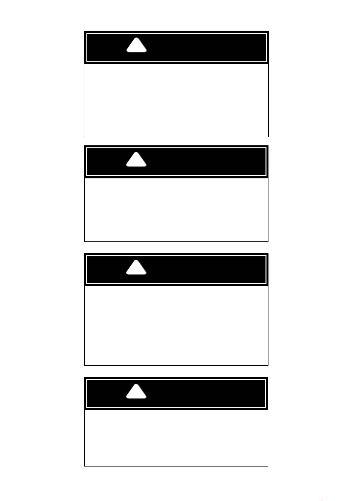
WARNING
ELECTRICALSHOCK HAZARD
WARNING
UNIT OPERATION AND SAFETY HAZARD
WARNING
PERSONAL INJURY AND ENVIRONMENTAL HAZARD
CAUTION
CUT HAZARD
Page 4
Failure to follow this warning could cause personal injury, death
and/or equipment damage.
Before performing service or maintenance operations on unit,
always turn off main power switch to unit and install lockout tag.
Unit may have more than one power switch.
Failure to follow this warning could cause personal injury, death
and/or equipment damage.
Puron® (R-410A) refrigerant systems operate at higher pressures
than standard R-22 systems. Do not use R-22 service equipment
or components on Puron refrigerant equipment.
Failure to follow this warning could cause personal injury, death
and/or equipment damage.
Relieve pressure and recover all refrigerant before system repair
or final unit disposal.
Wear safety glasses and gloves when handling refrigerants. Keep
torches and other ignition sources away from refrigerants and oils.
Failure to follow this warning could cause personal injury.
Sheet metal parts may have sharp edges or burrs. Use care and
wear appropriate protective clothing, safety glasses and gloves
when handling parts and servicing furnaces.
Page 5
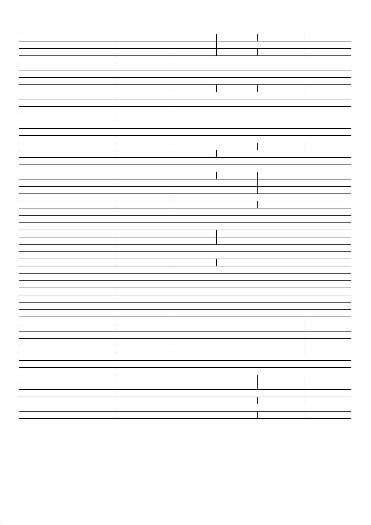
Table 1 - Unit Physical Data (English)
High Pressure Switch (Trip/ Reset) - (PSIG)
Face Area (ft2)
21.3 20.5
Face Area (ft2)
7.3 8.9
Evaporator Coil
Condenser Fan & Motor
350
4/15
1 / 15 x 15
3/4
Evaporator Fan & Motor section
Belt
Refrigeration System
630 / 505
25.1
30/4
22/3
Puron ® R410A
Acutrol
7500
Page 5
Unit 50TCM A07 D08 D09 D12 D14
Unit Dimensions - (in) 41.3x74.3x46.7 41.2x88.1x59.4
Unit Operating Weight - (LBS) 606 761 855 866 1078
49.3x88.1x59.4
Compressor No.# / Type 1 / Scroll
Refrigerant type
Circuts No.# 1
Charge per Circuit (1-Down/2-Up) - (LBS) 15.43 8.71/8.82 9.48/9.92 10.98/11.64 12.79/12.24
Metering Device
Filter Drier Qty 1
Low Pressure Switch (Trip/ Reset) - (PSIG)
Condenser Coil
Coil Type
Standard Coil Material
Rows / FPI 1 / 20 2 / 20
Coil test Pressure (PSIG)
Approx. Air Flow Rate (CFM) 5000 6400 7800
Quantity 1
Diameter (in) / No. of Blades 26/3
Motor Type
Motor HP - RPM 1/3-960
Coil Type
Standard Coil Material
Rows / FPI 4/15 3/15
Coil test Pressure (PSIG)
Drain Pan connection Size (in)
Return Air Filter Qty/ Size (in) 4 / 16x16x2 4 / 16x20x2
3/8" helical grooved copper tube, 0.75" Aluminum LSW fins.
2 / 17
Induction Motor - Totally Enclosed
3/8" helical grooved copper tube, 0.75" Aluminum LSW fins.
54 / 117
Cu/Al
450
2 1
Cu/Al
2 / Scroll
2
2
1-9501/3-1200
11.1
4 / 20x20x2
Fan Quantity / Fan Size (in) 1 / 10 x 10
Fan Type
Drive Type
Motor Type
Standard Static Drive
Motor Qty
Maximum BHP 1.4 2.4
FLA 3.4
Efficiency @ Full Load 81%
RPM Range 855 - 1211 665 - 903
Shaft Diamter (in) 7/8
Motor Frame Size
Medium Static Drive
Motor Qty
Maximum BHP 3.1 3.9
FLA 4.4 7.4
Efficiency @ Full Load
RPM Range 1077 - 1449 808 - 1082 837 - 1056
Shaft Diamter (in)
Motor Frame Size 56HZ 145TY
2.4
3.4
56Y
Centrifugal - Forward Blade
Induction Motor - Open Drip Proof
1
2
2.6
80%
570 - 808
5/8
56Y
1
81%
692 - 932
7/8
Page 6
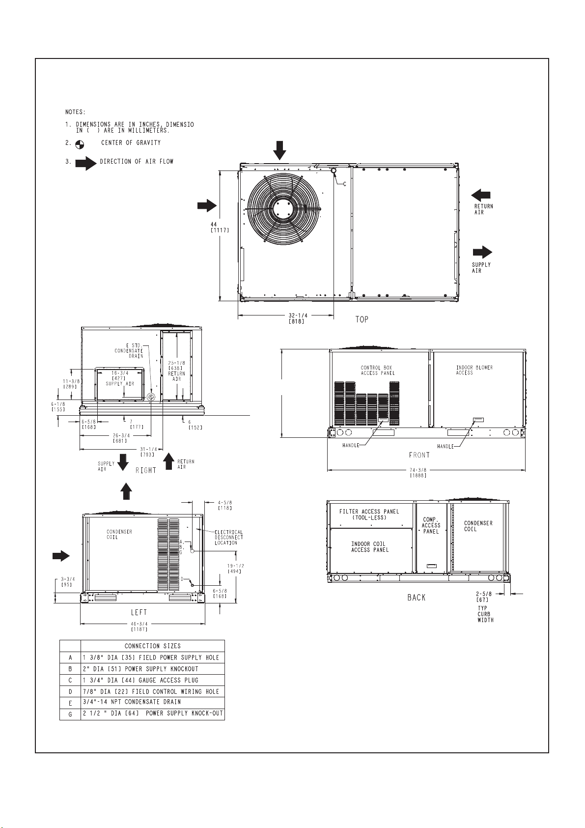
8:
&85%6:(,*+76',0(16,2167&007
Page 6
'LPHQVLRQV 7&."
Page 7
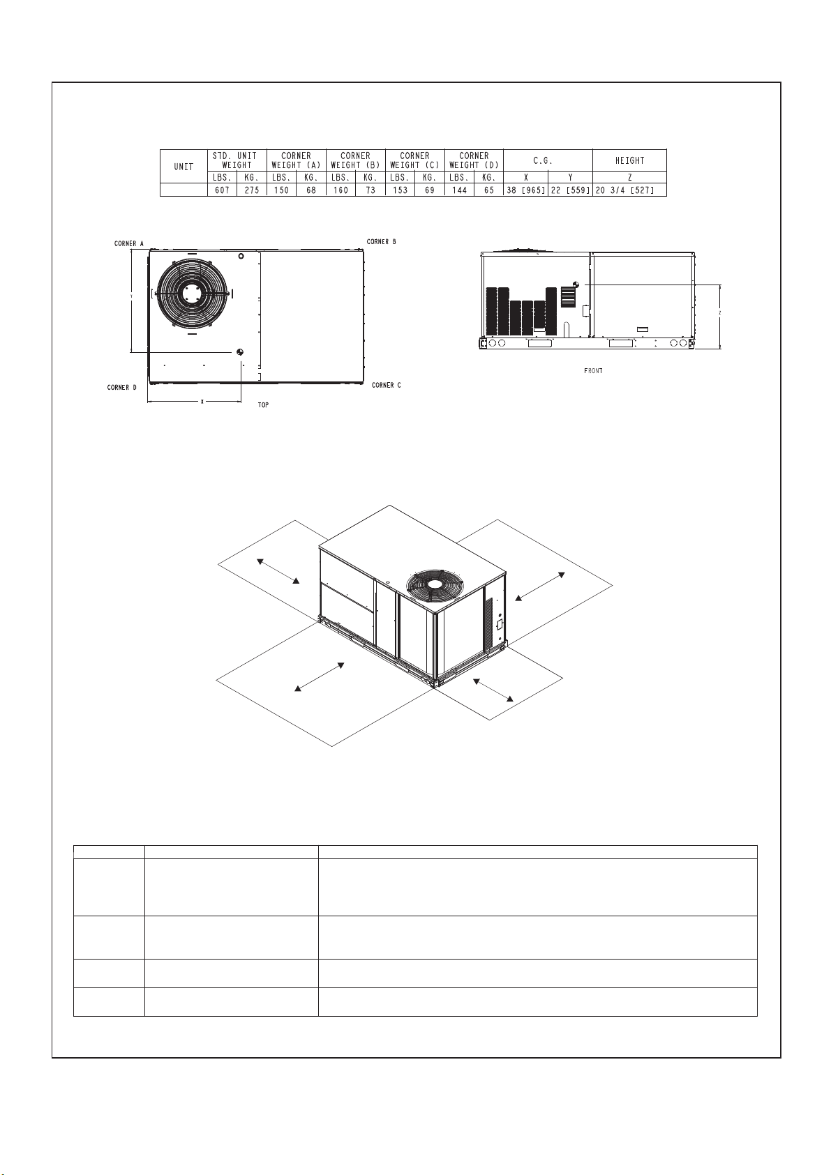
5$."
Page 7
&85%6:(,*+76',0(16,2167&007 (cont.)
'LPHQVLRQV7&."
C
B
6HUYLFH&OHDUDQFH
/2& ',0(16,21 &21',7,21
48---in (1219 mm) Unit disconnect is mounted on panel
A
B
C
D
18---in (457 mm) No disconnect, convenience outlet option
18---in (457 mm) Recommended service clearance
12---in (305 mm) Minimum clearance
42---in (1067 mm) Surface behind servicer is grounded (e.g., metal, masonry wall)
36---in (914 mm) Surface behind servicer is electrically non --- conductive (e.g., wood, fiberglass)
Special Check for sources of flue products within 10 --- ft of unit fresh air intake hood
36---in (914 mm) Side condensate drain is used
18---in (457 mm) Minimum clearance
42---in (1067 mm) Surface behind servicer is grounded (e.g., metal, masonry wall, another unit)
36---in (914 mm) Surface behind servicer is electrically non --- conductive (e.g., wood, fiberglass)
D
A
Page 8
&85%6:(,*+76',0(16,216 7&0'
5$.%
5$.%
Page 8
'LPHQVLRQV7&.%
Page 9
5$.%
5$.%
Page 9
&85%6:(,*+76',0(16,2167&0' (cont.)
'LPHQVLRQV 7&.%
C
B
6HUYLFH&OHDUDQFH
/2& ',0(16,21 &21',7,21
48---in (1219 mm) Unit disconnect is mounted on panel
36---in (914 mm) I f d i m e n s io n --- B i s 1 2 --- i n (3 0 5 m m )
A
B 12---in (305 mm) I f d im e n s i o n --- A is 3 6 --- i n ( 9 1 4 m m )
C
D
18---in (457 mm) No disconnect, convenience outlet option
18---in (457 mm) Recommended service clearance (use electric screwdriver)
12---in (305 mm) Minimum clearance (use manual ratchet screwdriver)
Special Check for sources of flue products within 10 - -- ft of unit fresh air intake hood
36---in (914 mm) Side condensate drain is used
18---in (457 mm) Minimum clearance
42---in (1067 mm) Surface behind servicer is grounded (e.g., metal, masonry wall, another unit)
36---in (914 mm) Surface behind servicer is electrically non--- conductive (e.g ., wood, fiberglass)
D
A
Page 10
&85%6:(,*+76',0(16,2167&0'
Page 10
5$.%
5$.%
'LPHQVLRQV7&.%
Page 11
5$.%
Page 11
5$.%
&85%6:(,*+76',0(16,2167&0'cont
$&/5&30'(3"7*5:$(
C10329
'LPHQVLRQV7&.%
C
B
6HUYLFH&OHDUDQFH
/2& ',0(16,21 &21',7,21
48---in (1219 mm) Unit disconnect is mounted on panel
A
B
C
D
18---in (457 mm) No disconnect, convenience outlet option
18---in (457 mm) Recommended service clearance
12---in (305 mm) Minimum clearance
42---in (1067 mm) Surface behind servicer is grounded (e.g., metal, masonry wall)
36---in (914 mm) Surface behind servicer is electrically non --- conductive (e.g., wood, fiberglass)
Special Check for sources of flue products within 10 --- ft of unit fresh air intake hood
36---in (914 mm) Side condensate drain is used
18---in (457 mm) Minimum clearance
42---in (1067 mm) Surface behind servicer is grounded (e.g., metal, masonry wall, another unit)
36---in (914 mm) Surface behind servicer is electrically non --- conductive (e.g., wood, fiberglass)
D
A
C08337
Page 12
2.0 – INSTALLATION
Page 12
2.1 – Jobsite Survey
Complete the following checks before installation.
1. Consult local building codes or the U.S.A. National Electrical Code (Ref: ANSI/NFPA 70, [American National
Standards Institute/National Fire Protection Association], latest revision) for special installation requirements.
2. Determine unit location (from project plans) or select unit location.
3. Check for possible overhead obstructions which may interfere with unit lifting or rigging.
2.2 – Plan for Unit Location
Select a location for the unit and its support system (curb or other) that provides for the minimum clearances required
for safety. This includes the clearance to combustible surfaces, unit performance and service access below, around
and above unit as specified in Fig - 1. For the centre of gravity coordinates, the position of the unit mounting holes,
and the weight distribution points, refer to the Unit Dimensional Drawing.
Fig. 1 Unit Clearance Diagram
NOTES:
1. Consider also the effect of adjacent units.
2. Do not install unit in an indoor location.
2.3 – Inspect Unit
Inspect unit for transportation damage. File any claim with transportation agency. Confirm before installation of unit
that voltage, amperage and circuit protection requirements listed on unit data place agree with power supply
provided.
2.4 – Rig and Place Unit
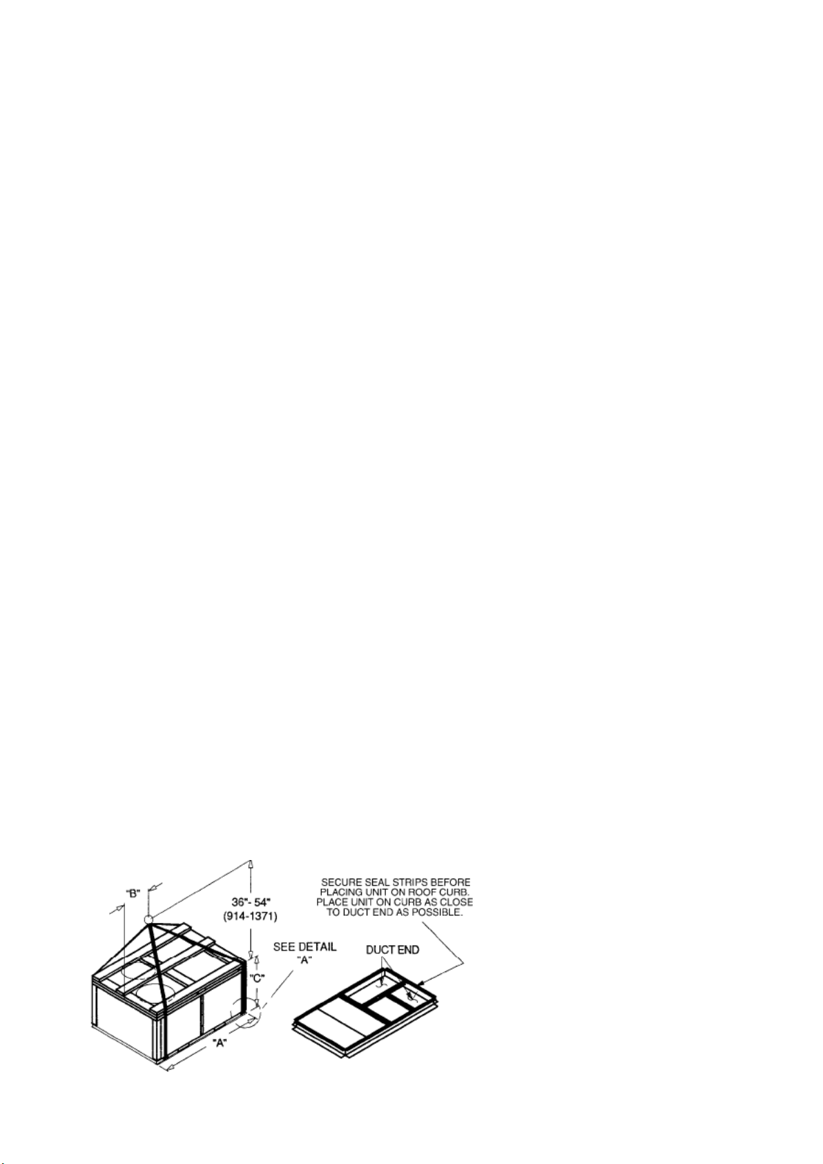
Keep unit upright and do not drop. Spreader bars are not required if top crating is left on unit.
Rollers may be used to move unit across a roof Level by using unit frame as a reference; leveling tolerance is± 1/16
in. per linear ft in any direction.
Four lifting holes are provided in ends of unit base rails as shown in Fig – 2 Refer to rigging instructions on unit.
Fig. 2 Rigging Diagram
Page 13
Roof mount - Check building codes for weight distribution requirements. Unit weight and dimensions is shown in unit
DIMENSIONS
A B C
LB
KG
IN
MM
IN
MM
IN
MM
50TCMA07
645
293
74.4
1888
38.0
965
41.4
1051
50TCMD08
1410
641
88.0
2235
41.0
1040
41.5
1055
50TCMD09
1525
693
88.0
2235
40.5
1030
49.5
1255
50TCMD12
1565
711
88.0
2235
40.0
1015
49.5
1255
50TCMD14
1720
782
88.0
2235
28.5
725
53.0
1345
IMPORTANT
UNIT DAM AGE HAZARD
Page 13
dimensional drawing and Table 2.
UNIT
Max Weight
Table – 2 Unit Weights and Dimensions
NOTES:
1. Remove boards at ends of unit and runners prior to rigging.
2. Rig by inserting hooks into unit base rails as shown. Use bumper boards for spreader bars.
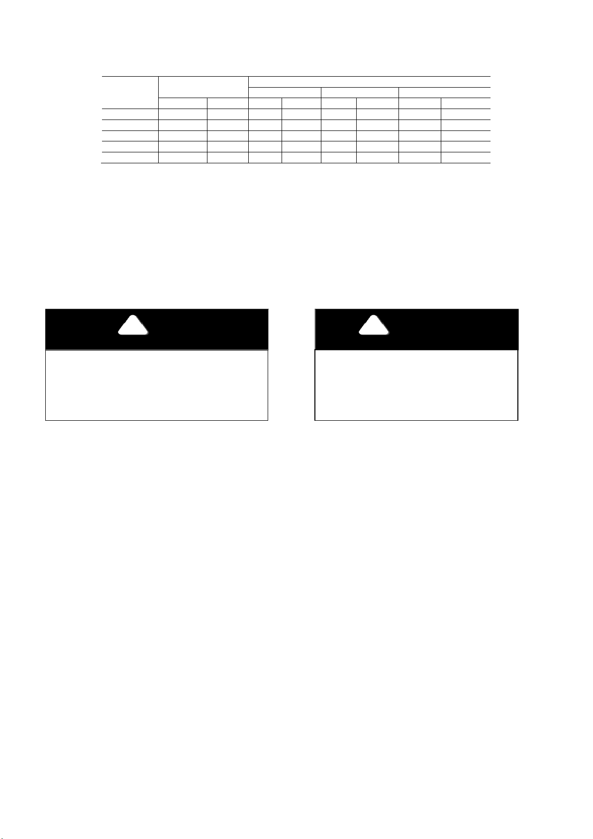
Crub should be level. This is necessary for unit drain to function properly. Unit leveling tolerances are shown in Fig.3
Fig. 3 Unit Leveling Tolerance
NOTE
CAUTION
All units are internally isolated against
vibration. If extra isolation required, please see
“Unit Dimensional Drawing”
Failure to follow this caution may result in
equipment damage.
All panels must be in place when rigging.
2.5 – Positioning and Clearance
Before positioning the unit, check the following:
• The permitted loading at the site is adequate or that appropriate strengthening measures have been taken.
• The unit is installed level on an even surface.
• Ensure access to the components (see “Unit Dimensional Drawings” & “Clearance Diagram” Fig 1).
• The number of support points is adequate and that they are in the right places.
• Although the unit is weatherproof guard against water from higher level runoff and overhangs.
Unit may be installed directly on wood flooring or on approved roof - covering material when roof curb is used. Do not
install unit in an indoor location. Do not locate air inlets near exhaust vents or sources of contaminated air.
Curb should be level. This is necessary for unit drain to function properly. Unit leveling tolerances are shown in Fig.3
Fig. 3 Unit Leveling Tolerance
Page 14
2.6 – Field Fabricate Ductwork
NOTE
Page 14
Secure all ducts to building structure. Use flexible duct connectors between unit and ducts as required (a space for 2.5
to 3ft is required in case of repairing or replacing the blower wheel). Insulate and weatherproof all external ductwork,
joints, and roof openings with counter flashing and mastic in accordance with applicable codes. Ducts passing through
an unconditioned space must be insulated and covered with a vapor barrier.
The 50TCM units with electric heat require a 2-in.clearance for the first 24-in. of ductwork. Outlet grilles must not lie
directly below unit discharge.
A 90-degree elbow must be provided in drain hole and must be removed in ductwork to comply with UL
(Underwriters’ Laboratories) codes for use with electric heat.
IMPORTANT
2.7 – Make Unit Duct Connections
Unit is shipped for side duct connections. Ductwork openings are shown in unit dimensional drawings.
2.8 – Trap Condensate Drain
The unit has one 3/4-in. condensate drain connection on the end of the condensate pan and an alternate connection
on the bottom. See Fig. 4. Unit airflow configuration does not determine which drain connection to use. Either
drain connection can be used with vertical or horizontal applications.
When using the standard side drain connection, ensure the red plug in the alternate bottom connection is tight. Do this
before setting the unit in place.
The red drain pan can be tightened with a 1/2-in. square socket drive extension. To use the alternate bottom drain
connection, remove the red drain plug from the bottom connection (use a 1/2-in. square socket drive extension) and
install it in the side drain connection.
The piping for the condensate drain and external trap can be completed after the unit is in place. See Fig. 6
Fig. 5 Condensate Drain Details Fig. 6 External Trap Condensate Drain
All units must have an external trap for condensate drainage. Install a trap at least 4-in. (102 mm) deep and
protect against freeze-up. If drain line is installed downstream from the external trap, pitch the line away from the unit
at 1-in. per 10 ft (25 mm in 3 m) of run. Do not use a pipe size smaller than the unit connection (3/4-in.).
2.9 – Make Electrical Connections
Field Power Supply – Unit is factory wired for voltage shown on nameplate. When installing units, provide disconnect
as per NEC (National Electrical Code) requirements, of adequate size. All field wiring must comply with NEC and local
Page 15
requirements. Route power lines through the corner post openings as shown in unit dimensional drawings. If a de-
ELECTRIC SHOCK HAZARD
FIRE HAZARD
Page 15
energize via a unit disconnect switch is desired, connect the source leads to the unit power terminal block. Refer to
unit label diagram for additional information. Refer to unit label diagram for additional information. Field power wires
are connected to the unit power terminal block (see wiring diagram label for control box arrangement) max wire size is
#4 AWG (copper only).
NOTE: Check all factory and field electrical connections for tightness. Field--supplied wiring shall conform to the
limitations of 63°F (33°C) rise.
WARNING
Do not use gas piping as an electrical ground. Unit cabinet must have an uninterrupted, unbroken electrical ground to minimize
the possibility of personal injury if an electrical fault should occur. This ground may consist of electrical wire connected to unit
ground lug in control compartment, or conduit approved for electrical ground when installed in accordance with local electrical
codes or in absence of local codes, it is recommended that U.S.A standard ANSI/NFPA 70, National Electrical Code be followed.
Failure to follow this warning could result in intermittent operation or performance satisfaction. Do not connect aluminum wire
Failure to follow this warning could result in personal injury or death.
WARNING
between disconnect and air conditioning unit. Use copper wire only (See Fig. 7)
Fig. 7 Disconnect Switch and Unit
When installing units, provide a disconnect switch per NEC (National Electric Code) of adequate size. Disconnect
sizing data is provided on the unit informative plate. Locate on unit cabinet or within sight of the unit per national or
local codes. Do not cover unit informative plate if mounting the disconnect on the unit cabinet.
All field wiring must comply with the NEC and all local codes. Size wire based on MCA (Minimum Circuit Amps) on the
unit informative plate, connections to the unit power terminal block and equipment ground. Maximum wire size is #4
ga AWG per pole.
Provide a ground-fault and short –circuit over-current protection device (fuse or breaker) per NEC Article 440 (or local
codes). Refer to unit informative data plate for MOCP (Maximum Over-current Protection) device size. All field wiring
must comply with NEC and local requirements.
1. Install power wiring conduit through side panel openings. Install conduit between disconnect and control box.
2. Install power lines to terminal block connections.
Voltage to compressor terminals during operation must be within voltage range indicated on unit nameplate. On 3 –
phase units, voltages between phases must be balanced within 2% and the current within 10%. Use the formula
shown in the legend of the Electrical Data Table to determine the percent of voltage imbalance. Operation on improper
lines voltage or excessive phase imbalance constitutes abuse and may cause damage to electrical components. Such
operation would invalidate any applicable Carrier warranty.
Page 16

Field Control Wiring – The 50TCM unit requires an external temperature control device. This device can be a
Page 16
thermostat (field--supplied) or a PremierLink controller (field--installed accessory, for use on a Carrier Comfort
Network or as a standalone control)
Thermostat – Install a Carrier--approved accessory thermostat according to installation instructions included with the
accessory. Select a two--stage cooling thermostat. Locate the thermostat accessory on a solid wall in the conditioned
space to sense average temperature in accordance with the thermostat installation instructions.
If the thermostat contains a logic circuit requiring 24—v power, use a thermostat cable or equivalent single leads of
different colors with minimum of seven leads. If the thermostat does not require a 24--v source (no “C” connection
required), use a thermostat cable or equivalent with minimum of six leads. Check the thermostat installation
instructions for additional features which might require additional conductors in the cable.
For wire runs up to 15 m (50 ft.), use no. 18 AWG (American Wire Gage) insulated wire (35_C minimum). For 15 to 23
m (50 to 75 ft.), use no. 16 AWG insulated wire (35_C minimum). For over 23 m (75 ft.), use no. 14 AWG insulated
wire (35_C minimum). All wire sizes larger than no. 18 AWG cannot be directly connected to the thermostat and will
require a junction box and splice at the thermostat.
Fig. 8 Typical Low-Voltage Control Connections
3.0 – START-UP INSTRUCTIONS
PRIOR to unit start-up use the following instructions and start-up checklist provided on the last page.
3.1– Unit Preparation
Check that unit has been installed in accordance with these installation instructions and all applicable codes.
3.2 – Internal Wiring
Check all electrical connections in unit control boxes; tighten as required.
3.3 – Compressor Mounting
Compressors are internally spring mounted. Do not loosen or remove compressor hold down bolts.
3.4 – Refrigerant Service Ports
Each refrigerant system has a total of 2 Schrader type Service gage ports. One port is located on the suction line,
one on the compressor discharge line, and one on the liquid line. In addition Schrader-type valves are located
underneath the pressure switches. Be sure that caps on the ports are tight.
Page 17
3.5 – Compressor Rotation
IMPORTANT
Page 17
It is important to be certain the compressors are rotating in the proper direction. To determine whether or not
compressors are rotating in the proper direction:
1. Connect service gages to suction and discharge pressure fittings.
2. Energize the compressor.
3. The suction pressure should drop and the discharge pressure should rise, as is normal on any start-up.
If the suction pressure does not drop and the discharge pressure does not rise to normal levels:
1. Note that the evaporator fan is probably also rotating in the wrong direction.
2. Turn off power to the unit.
3. Reverse any two of the compressor lead wires.
4. Turn on power to the compressor.
5. Check also phase monitor all ok green led before proceeding.
The suction and discharge pressure levels should now move to their normal start-up levels.
NOTE
For wire runs up to 50 ft, use no. 18 AWG insulated wire. For 50 to 75 ft, use no. 16 AWG insulated wire. For over 75 ft, use no.
14 AWG insulated wire. All wire larger than no. 18 AWG cannot be directly connected to the thermostat and will require a
3.6 - Evaporator Fan
Fan belt and variable pulleys are factory installed. Remove tape from the fan pulley. See Table 4 Fan Performance
data. Be sure that fans rotate in the proper direction. See Table 3 Fan RPM at various fan motor pulley settings. To
alter fan performance, see Evaporator Fan Performance Adjustment section.
3.7– Condenser Fans and Motors
Fans and motors are factory set. Refer to Condenser-Fan Adjustment Section as required.
3.8– Return – Air Filters
Check that correct filters are installed in filter tracks. See Table 1 Physical data. Do not operate unit without return
air filters.
3.9 – Base Unit Operation
COOLING, UNITS — when thermostat calls for cooling, terminals G and Y1 are energized. The indoor (evaporator)
fan contactor (IFC), and compressor contactor no. 1 (C1) are energized and evaporator-fan motor, compressor no. 1
and condenser fans start. The condenser-fan motors run continuously while unit is cooling. If the thermostat calls for
a second stage of cooling by energizing Y2, compressor contactor no. 2 (C2) is energized and compressor no. 2
starts.
HEATING, UNITS — (If Accessory or Optional Heater is installed) — upon a call for heating through terminal W1,
IFC and heater contactor no. 1 (HC1) are energized.
junction box and splice at the thermostat.
Page 18
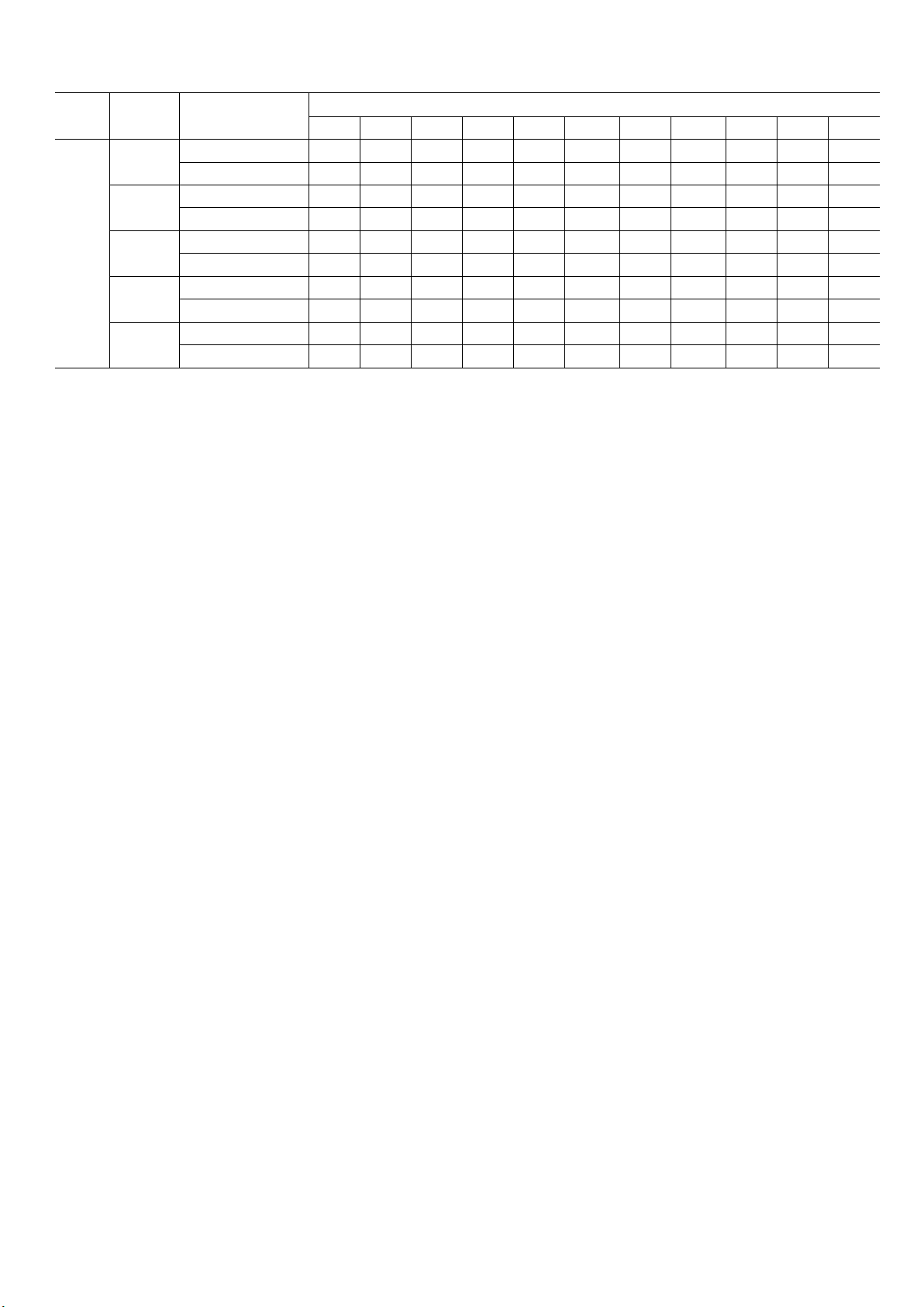
Table – 3 Fan RPM at Motor Pulley Settings
MOTOR PULLEY TURNS OPEN - ENGLISH
0
1/3
1
1 1/3
2
2 1/3
3
3 1/3
4
4 1/3
5
Standard Static
Medium Static
Standard Static
Medium Static
Standard Static
Standard Static
Medium Static
Standard Static
903
Medium Static
1056
Page 18
Freq.
50Hz
Bold RPM is factory setting
Unit
50TCM
A07
D08
D09
D12
D14
Drive Package
Medium Static
1211 1176
1449 1362 1330 1298
808 784 760 736 713 689
932 875
808 784 760 736 713 689
932 875
808 784
1087 1021 998 974 950 926
1140
879 855 831
998 980 962
1104 1069 1033 998 962 926 891 855
855
855
760
835 814 794 774 753 733 713 692
835 814 794 774 753 733 713 692
736 713 689 665 641 618 594 570
1267
808
944
1235 1203 1172 1140 1108 1077
784 760 736 713 689 665
926 908 891 873 855 837
665
665
903
641 618 594 570
641 618 594 570
879 855 831 808
4.0 – SERVICE
4.1 – Cleaning
Inspect unit interior at beginning of each heating and cooling season and as operating conditions require. Remove
unit top panel and/or side panels for access to unit interior.
EVAPORATOR COIL — Clean as required with a commercial coil cleaner.
CONDENSER COIL — Clean condenser coil annually and as required by location and outdoor-air conditions.
Inspect coil monthly and clean as required.
CONDENSATE DRAIN — Check and clean each year at start of cooling season.
FILTERS — Clean or replace at start of each heating and cooling season, or more often if operating conditions
require. Refer to Table 1 “Physical Data” type and size.
4.2 – Lubrication
Compressors are charged with the correct amount of oil at the factory.
Replacing Compressor - In the case of a motor burnout, the majority of contaminated will be removed with the
compressor. The rest of the oil is cleaned through the use of suction and liquid line filter driers. A 100% activated
alumna suction line filter drier is recommended but must be removed after 72 hours.
The compressor contains POE oil. POE oil has a high affinity for moisture. Do not remove the compressor’s tube
plugs until ready to insert the unit suction and discharge tube ends. The discharge connection plug should be
removed first before pulling the suction connection plug to allow the dry air pressure inside the compressor to
escape.
Note: This is only valid for the R410A systems.
Page 19
UNIT DAM AGE HAZARD
Page 19
CAUTION
1. The compressor is in a Puron® refrigerant system and uses a (POE) lubricant Emkarate RL 32 3MAF. In the field
the oil level could be topped up with Mobil EAL Arctic 22 CC if 3MAF is not available. POE oil is extremely
hygroscopic, meaning it absorbs water readily. POE oils can absorb 15 times as much as other oils designed for
HCFC and CFC refrigerants. Avoid exposure of the oil to the atmosphere.
2. Ensure that system is not subjected to liquid abuse. Turn the crankcase heater on 12 hours before starting the
compressor.
CONDENSER AND EVAPORATOR-FAN MOTOR BEARINGS – The condenser and evaporator-fan motors have
permanently-sealed bearings, so no field lubrication is necessary.
4.3 – Evaporator Fan Performance Adjustment
NOTE: To remove belts only, follow Steps 1, 2 & 6. Fan motor pulleys are factory set speed shown in Table 6.
To change fan speeds:
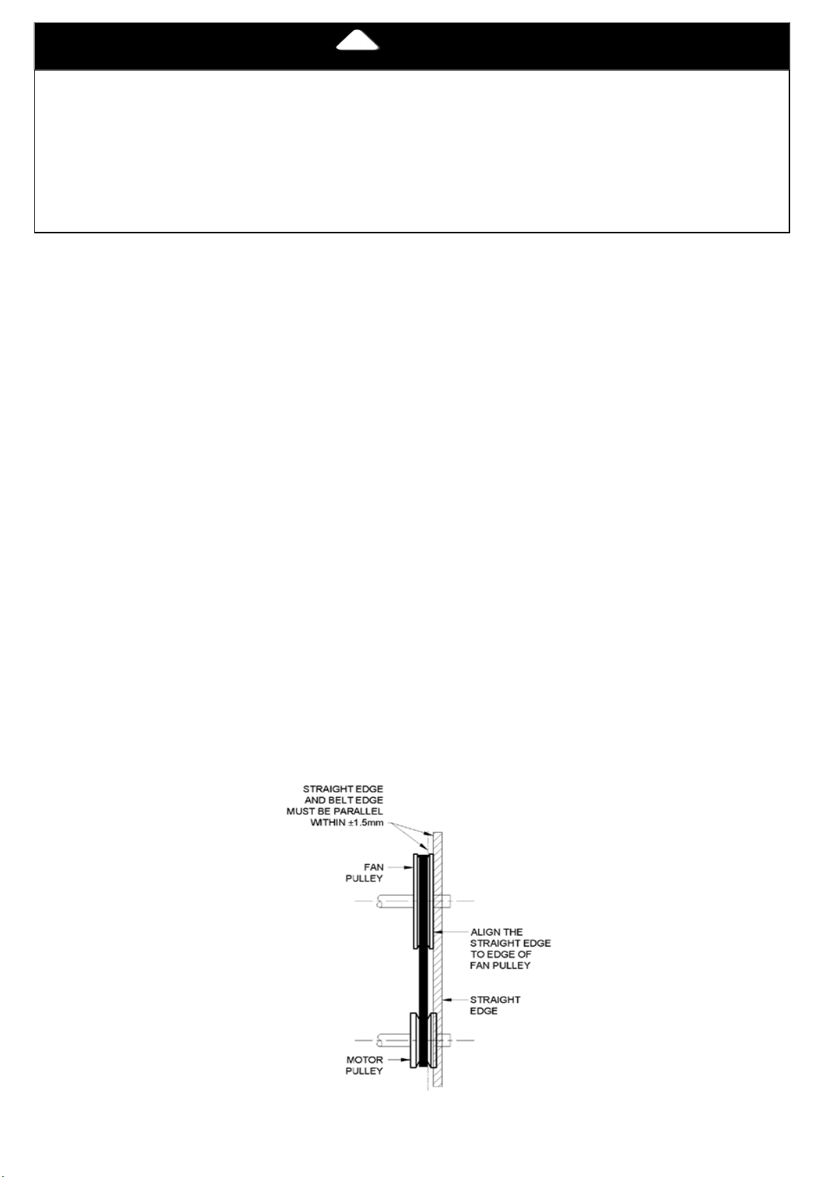
To align fan and motor pulleys:
4.4 – Evaporator Fan Service and Replacement
1. Shut off unit power supply.
2. Loosen belt by loosening fan motor mounting plate nuts. Slide the Motor and remove belt.
3. Loosen movable-pulley flange setscrew (See Fig.9).
4. Screw movable flange toward fixed flange to increase speed and away from fixed flange to decrease
speed. Increasing fan speed increases load on motor. Do not exceed maximum speed specified in Table 3.
See Table 4 for air flow.
5. Set movable flange at nearest keyway of pulley hub and tighten setscrew. (See Table 1 & 6 for speed
change for each full turn of pulley flange.)
6. Replace and tighten belts. See Belt Tension Adjustment section on Table 1.
1. Loosen fan pulley setscrews.
2. Slide fan pulley along fan shaft.
3. Make angular alignment by loosening motor from mounting plate.
1. Remove supply-air section panel (The bolts holding the flexible connection to the panel should be
removed).
2. Remove the Control Side panel.
3. Remove the Belt (refer to the previous section for Belt removal).
4. Remove the locking device of the hub & shaft from the both sides; it can be accessed throw the fan side
panel.
5. Pull the shaft gently from the control side, the blower will fall inside the blower housing.
6. Loosen the (lower) first two bolts from each side of the scroll fan housing mid-plate. This can be done from
the supply panel side, now the fan can be removed easily from the supply panel side.
7. To assemble the fan, reverse the above procedure.
Failure to follow this caution may result in damage to components.
Fig. 9 Evaporator – Fan Pulley Alignment and Adjustment
Page 20

4.5 – Belt Tension Adjustment.
Page 20
To adjust belt tension:
1. Loosen fan motor bolts.
2. Adjust belt tension by sliding the motor on the mounting base.
3. Tighten nuts.
4. Adjust bolts and nut on mounting plate to secure motor in fixed position.
4.6 – Condenser-Fan Adjustment
1. Shut off unit power supply.
2. Remove fan top-grille assembly and loosen fan hub screws.
3. Adjust fan height on unit, using a straightedge placed across the fan orifice.
4. Tighten setscrews
Fig. 10 Condenser – Fan Adjustment
4.7 – Refrigerant Charge
Amount of refrigerant charge is listed on unit nameplate and in Table 1. Refer to Carrier GTAC II; Module 5;
Charging, Recovery, Recycling, and Reclamation section for charging methods and procedures. Unit panels must be
in place when unit is operating during charging procedure.
NOTE: Do not use recycled refrigerant as it may contain contaminants.
NO CHARGE — Use standard evacuating techniques. After evacuating system, weight in the specified amount of
refrigerant (refer to Table 1).
LOW CHARGE COOLING — Using cooling charging chart according to the size of the unit Add or remove refrigerant
until conditions of the chart are met. Note that charging chart is different from those normally used. An accurate
pressure gage and temperature-sensing device is required. Charging is accomplished by ensuring the proper amount
of liquid sub-cooling. Measure liquid line pressure at the liquid line service valve using pressure gage.
Connect temperature sensing device to the liquid line near the liquid line service valve and insulate it so that outdoor
ambient temperature does not affect reading.
TO USE THE COOLING CHARGING CHART — Use the above temperature and pressure readings, and find the
intersection point on the cooling charging chart. If intersection point on chart is above line, add refrigerant. If
intersection point on chart is below line, carefully recover some of the charge. Recheck suction pressure as charge
is adjusted.
NOTE: Indoor-air CFM must be within normal operating range of unit. All outdoor fans must be operating.
Page 21
4.8 – Protective Devices
IMPORTANT
Page 21
Compressor Protection – Each compressor is internally protected against over temperature.
To reset, manually move the thermostat setting.
Evaporater and Condenser-fan Motor Protection — Each Evaporator and Condenser-fan motor is
internally protected against over temperature.
High and Low-Pressure switches — If either switch trips, it will be automatically reset when fault is cleared.
After prolonged shutdown or servicing in cold weather, energize the crankcase heaters for 12 hours before starting the
4.9 – Control Circuit, 24-V
This control circuit is protected against over-current by a circuit breaker. Breaker can be reset manually if it trips,
determine cause of trouble before resetting.
NOTE
compressors.
5.0 – REPLACEMENT PARTS
A complete list of replacement parts may be obtained from any Carrier distributor.
Page 22
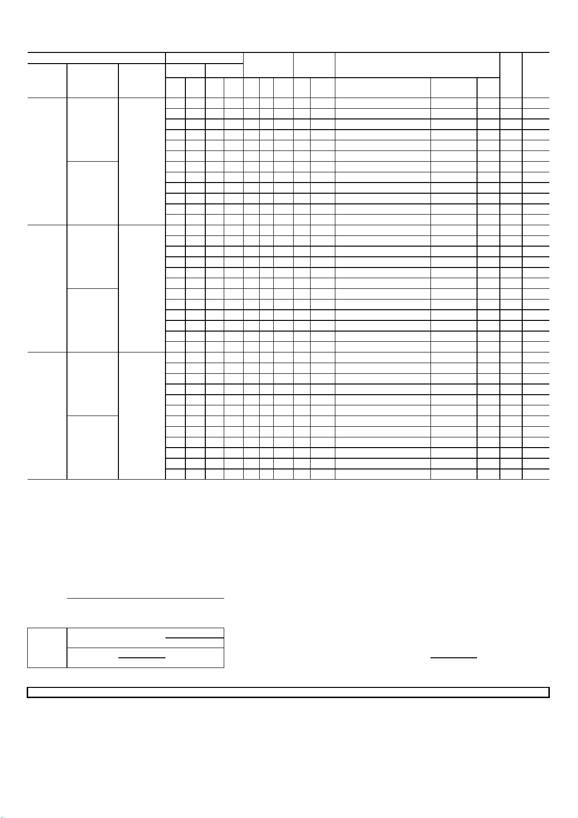
Table 4 - Electrical Data
404 - 397
457 - 397
Determine maximum deviation from average voltage.
392 + 404 + 395
Maximum Deviation is 7v.
IFM -
RLA -
MCA - Minimum Circuit Amps
MOCP - Maximum Overcurrent Protection
Unbalanced 3-Phase Supply Voltage
Supply
Page 22
Unit Size
A07
D08
D09
50TCM
Drive
package
Indoor Motor
Standard
Medium
Standard
Medium
Standard
Medium
Power
V / Ph / Hz
400/3/50
400/3/50
400/3/50
Compressor
No.1 No.2
RLA LRA RLA LRA Qty HP FLA HP FLA Heater P.N
10.6 74.0 - - 1 1/3 1.6 1.4 2.6 - - -
10.6 74.0 - - 1 1/3 1.6 1.4 2.6 CRHEATER106A00
10.6 74.0 - - 1 1/3 1.6 1.4 2.6 CRHEATER108A00
10.6 74.0 - - 1 1/3 1.6 1.4 2.6 CRHEATER109A00
10.6 74.0 - - 1 1/3 1.6 1.4 2.6 CRHEATER108A00,108A00
10.6 74.0 - - 1 1/3 1.6 1.4 2.6 CRHEATER108A00,109A00
10.6 74.0 - - 1 1/3 1.6 2.4 3.4 - 0 0.0
10.6 74.0 - - 1 1/3 1.6 2.4 3.4 CRHEATER106A00
10.6 74.0 - - 1 1/3 1.6 2.4
10.6 74.0 - - 1 1/3 1.6 2.4 3.4 CRHEATER109A00
10.6 74.0 - - 1 1/3 1.6 2.4 3.4 CRHEATER108A00,108A00
10.6 74.0 - - 1 1/3 1.6 2.4 3.4 CRHEATER108A00,109A00
6.1 43.0 6.1 43.0 2 1/2 1.8 2.0 2.6 - - -
6.1 43.0 6.1 43.0 2
6.1 43.0 6.1 43.0 2
6.1 43.0 6.1 43.0 2
6.1 43.0 6.1 43.0 2
6.1 43.0 6.1 43.0 2
6.1 43.0
6.1 43.0 6.1 43.0 2
6.1 43.0 6.1 43.0 2
6.1 43.0 6.1 43.0 2
6.1 43.0 6.1 43.0 2
6.1 43.0 6.1 43.0 2
7.6 51.5 6.2 52.0 2 1/2 1.8 2.0 2.6 - 0 0.0
7.6 51.5 6.2 52.0 2 1/2 1.8 2.0 2.6 CRHEATER116A00
7.6 51.5 6.2 52.0 2 1/2 1.8 2.0 2.6 CRHEATER113A00
7.6 51.5 6.2 52.0 2 1/2 1.8 2.0 2.6 CRHEATER114A00
7.6 51.5 6.2 52.0 2 1/2 1.8 2.0 2.6 CRHEATER115A00
7.6 51.5 6.2 52.0 2 1/2 1.8 2.0 2.6 CRHEATER114A00,116A00
7.6 51.5 6.2 52.0 2 1/2 1.8 2.4 3.4 - - -
7.6 51.5 6.2 52.0 2 1/2 1.8 2.4 3.4 CRHEATER116A00
7.6 51.5 6.2 52.0 2 1/2 1.8 2.4 3.4 CRHEATER113A00
7.6 51.5 6.2 52.0 2 1/2 1.8 2.4 3.4 CRHEATER114A00
7.6 51.5 6.2 52.0 2 1/2 1.8 2.4 3.4 CRHEATER115A00
7.6 51.5 6.2 52.0 2 1/2 1.8 2.4 3.4 CRHEATER114A00,116A00
6.1
43.0 2
OFM IFM Electric Heater
Application
CRHEATER108A00
3.4
1.8 2.0 2.6 CRHEATER116A00
1/2
1.8 2.0 2.6 CRHEATER113A00
1/2
1.8 2.0 2.6 CRHEATER114A00
1/2
1.8 2.0 2.6 CRHEATER115A00
1/2
1.8 2.0 2.6 CRHEATER114A00,116A00
1/2
1.8 2.4 3.4 - - -
1/2
1.8 2.4 3.4 CRHEATER116A00
1/2
1.8 2.4 3.4 CRHEATER113A00
1/2
1.8 2.4 3.4 CRHEATER114A00
1/2
1.8 2.4 3.4 CRHEATER115A00
1/2
1.8 2.4 3.4 CRHEATER114A00,116A00
1/2
(KW)
4.2 6.0 17.5
8.0 11.5 17.6
9.7 14.0 20.8
16.0 23.1 32.1
17.7 25.6 35.3
4.2 6.0 18.3
8.0 11.5 18.6
9.7 14.0 21.8
16.0 23.1 33.1
17.7 25.6 36.3
9.7 13.9 20.6
11.5 16.5 23.9
19.3 27.9 38.1
22.9 33.1 44.6
29.0 41.8 55.5
9.7 13.9 21.6
11.5 16.5 24.9
19.3 27.9 39.1
22.9 33.1 45.6
29.0 41.8 56.5
9.7 13.9 21.9
11.5 16.5 23.9
19.3
22.9 33.1 44.6
29.0 41.8 55.5
9.7 13.9 22.7
11.5 16.5 24.9
19.3 27.9 39.1
22.9 33.1 45.6
29.0 41.8 56.5
FLA
27.9 38.1
MCA
17.5
18.3
19.9
20.7
21.9
22.7
MOCP
25
25
25
25
25
30
25
25
25
25
30
30
25
25
25
40
45
60
25
25
25
40
50
60
25
25
25
40
45
60
30
30
30
40
50
60
Legend and Notes for Electrical Data Table
FLA - Full Load Amps OFM - Outdoor (Condenser) Fan Motor
Indoor (Evaporator) Fan Motor
LRA - Locked Rotor Amps APP - Application power at rated power supply voltage
Minimum Voltage: 360V , Maximum Voltage: 440V on 400/3/50
Never operate a motor where phase imbalance in supply voltage is greater than 2%.
Use the following formula to determine the percentage of voltage imbalance
= 100 X
AB = 392v
BC = 404v Determine Percentage Voltage Imbalance.
AC = 395v
Maximum Deviation From Average Voltage
Average Voltage
Example: Supply Voltage is 400V - 3Ph - 50Hz
Average Voltage =
1191 7
= = 397V
3 397
This amount of phase imbalance is satisfactory as it is below the maximum allowable 2%
IMPORTANT: If the supply voltage phase imbalance is more than 2% contact your local electric utility company
Rated Load Amps
3
(AB) 397 - 392 =5v
(BC)
(AC)
% Voltage
Imbalance
=7v
=2v
= 100 X = 1.76%
Page 23
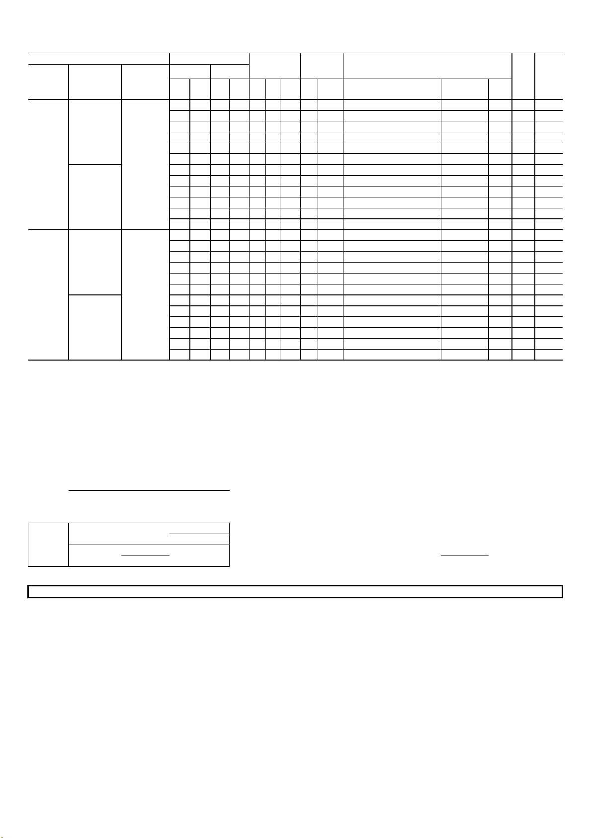
Table 4 - Electrical Data (Continued)
(KW)
397 - 392
LRA -
APP
IFM -
FLA -
OFM -
RLA -
This amount of phase imbalance is satisfactory as it is below the maximum allowable 2%
Supply
Page 23
Unit Size
D12
D14
50TCM Compressor
Drive
package
Indoor Motor
Standard
Medium
Standard
Medium
Power
V / Ph / Hz
400/3/50
400/3/50
No.1 No.2
RLA LRA RLA LRA Qty HP FLA HP FLA Heater P.N
7.8 51.5 7.8 51.5 1 1 3.4 2.0 2.6 - - - 23.6 30
7.8 51.5 7.8 51.5 1 1 3.4 2.0 2.6 CRHEATER116A00
7.8 51.5 7.8 51.5 1 1 3.4 2.0 2.6 CRHEATER113A00
7.8 51.5 7.8 51.5 1 1 3.4 2.0 2.6 CRHEATER114A00
7.8 51.5 7.8 51.5 1 1 3.4 2.0 2.6 CRHEATER115A00
7.8 51.5 7.8 51.5 1 1 3.4 2.0 2.6 CRHEATER114A00,116A00
7.8 51.5 7.8 51.5 1 1 3.4 3.1 4.4 - 0 0.0 25.4 30
7.8 51.5 7.8 51.5 1 1 3.4 3.1 4.4 CRHEATER116A00
7.8 51.5 7.8 51.5 1 1 3.4 3.1 4.4 CRHEATER113A00
7.8 51.5 7.8 51.5 1 1 3.4
7.8 51.5 7.8 51.5 1 1 3.4 3.1 4.4 CRHEATER115A00
7.8 51.5 7.8 51.5 1 1 3.4 3.1 4.4 CRHEATER114A00,116A00
9.7 64.0 10.6 74.0 1 1 3.4 2.4 3.4 - - - 29.5 35
9.7 64.0 10.6 74.0 1 1 3.4 2.4 3.4 CRHEATER116A00
9.7 64.0 10.6 74.0 1 1 3.4 2.4 3.4 CRHEATER113A00
9.7 64.0 10.6 74.0 1 1 3.4 2.4 3.4 CRHEATER114A00
9.7 64.0 10.6 74.0 1 1 3.4 2.4 3.4 CRHEATER115A00
9.7 64.0 10.6 74.0 1 1 3.4 2.4 3.4 CRHEATER114A00,116A00
9.7 64.0 10.6 74.0 1 1 3.4 3.9 7.4 - - - 33.5 40
9.7
64.0 10.6 74.0 1 1 3.4 3.9 7.4 CRHEATER116A00
9.7 64.0 10.6 74.0 1 1 3.4 3.9 7.4 CRHEATER113A00
9.7 64.0 10.6 74.0 1 1 3.4 3.9 7.4 CRHEATER114A00
9.7 64.0 10.6 74.0 1 1 3.4 3.9 7.4 CRHEATER115A00
9.7 64.0 10.6 74.0 1 1 3.4 3.9 7.4 CRHEATER114A00,116A00
OFM
IFM Electric Heater
3.1 4.4 CRHEATER114A00
Application
9.7 13.9
11.5 16.5
19.3 27.9
22.9 33.1
29 41.8
9.7 13.9
11.5 16.5
19.3 27.9
22.9 33.1
29 41.8
9.7 13.9
11.5 16.5
19.3 27.9
22.9 33.1
29 41.8
9.7 13.9
11.5 16.5
19.3 27.9
22.9 33.1
29 41.8
FLA
MCA
MOCP
23.6 30
23.9 30
38.1 40
44.6 45
55.5 60
25.4 30
26.1 30
40.4 45
46.9 50
57.8 60
29.5 35
29.5 35
39.1 40
45.6 50
56.5 60
33.5 40
33.5 40
44.1 45
50.6 60
61.5 70
Legend and Notes for Electrical Data Table
Full Load Amps
Indoor (Evaporator) Fan Motor
Locked Rotor Amps
MCA - Minimum Circuit Amps
Minimum Voltage: 360V , Maximum Voltage: 440V on 400/3/50
Unbalanced 3-Phase Supply Voltage
Never operate a motor where phase imbalance in supply voltage is greater than 2%.
Use the following formula to determine the percentage of voltage imbalance
= 100 X
AB = 392v
BC = 404v Determine Percentage Voltage Imbalance.
AC = 395v
Maximum Deviation From Average Voltage
Average Voltage
Example: Supply Voltage is 400V - 3Ph - 50Hz
Average Voltage =
1191 7
= = 397V
IMPORTANT: If the supply voltage phase imbalance is more than 2% contact your local electric utility company
392 + 404 + 395 Maximum Deviation is 7v.
3 397
Outdoor (Condenser) Fan Motor
Rated Load Amps
- Application power at rated power supply voltage
MOCP - Maximum Overcurrent Protection
Determine maximum deviation from average voltage.
(AB)
(BC) 404 - 397 =7v
(AC) 457 - 397 =2v
3
% Voltage
Imbalance
=5v
= 100 X = 1.76%
Page 24
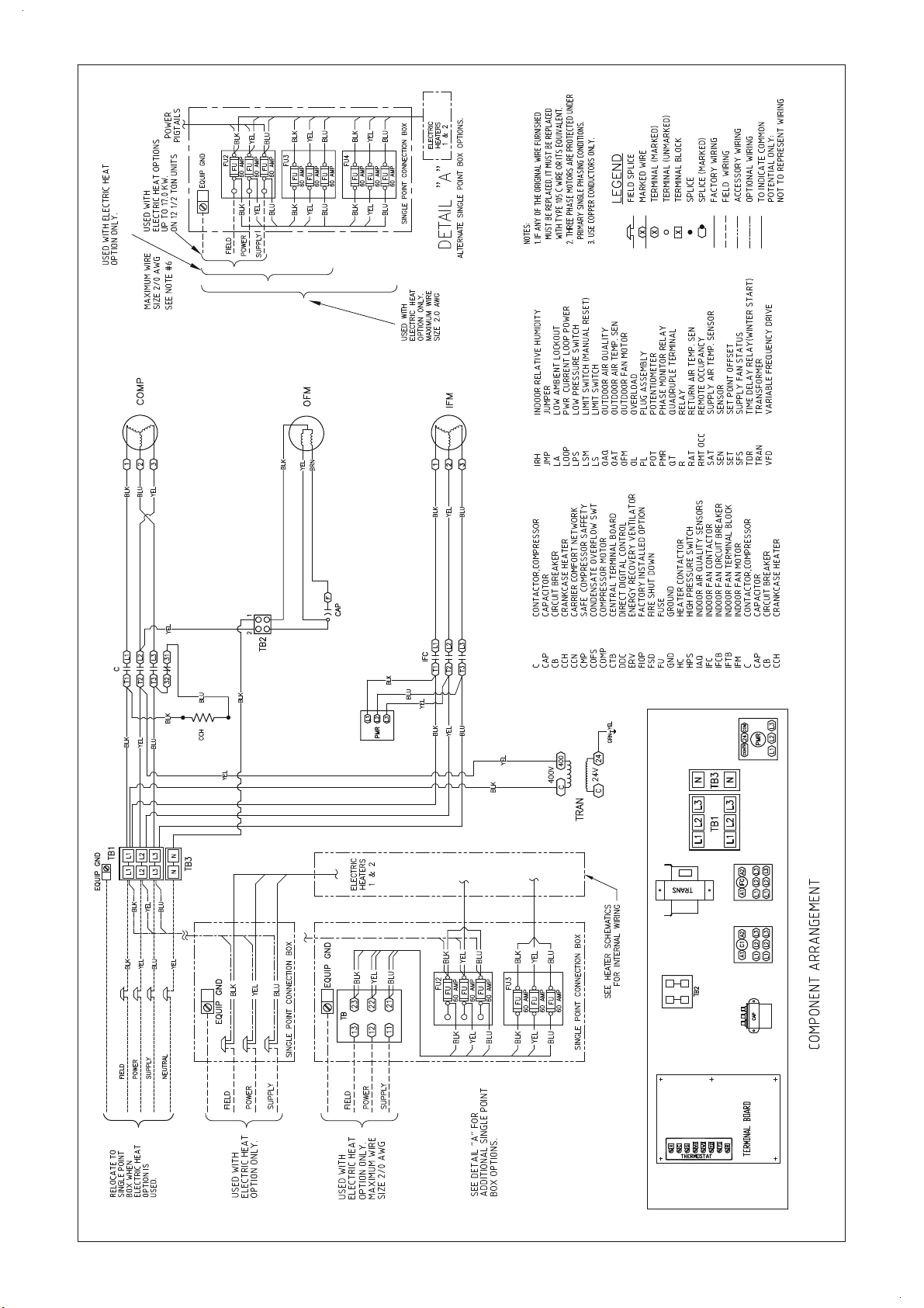
Typical Wiring Schematic 50TCMA07 400V
Page 24
Page 25
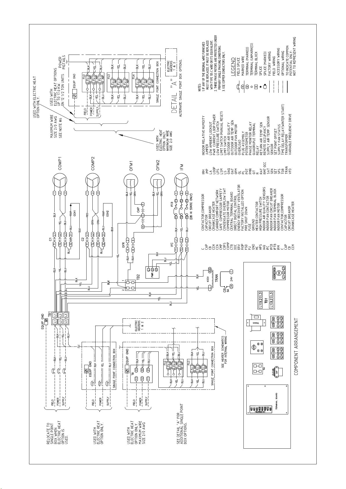
Typical Wiring Schematic 50TCMD08-09 400V
Page 25
Page 26
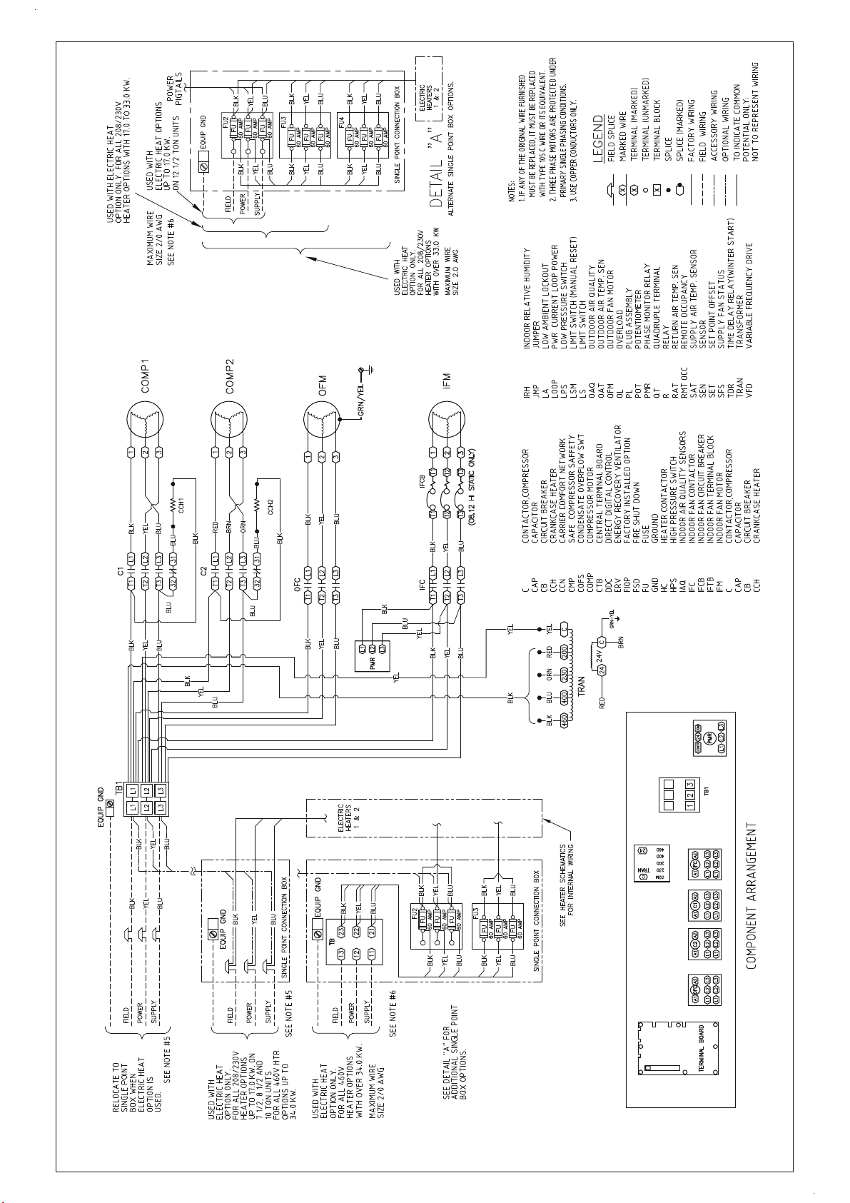
Typical Wiring Schematic 50TCMD12-14 400V
Page 26
Page 27
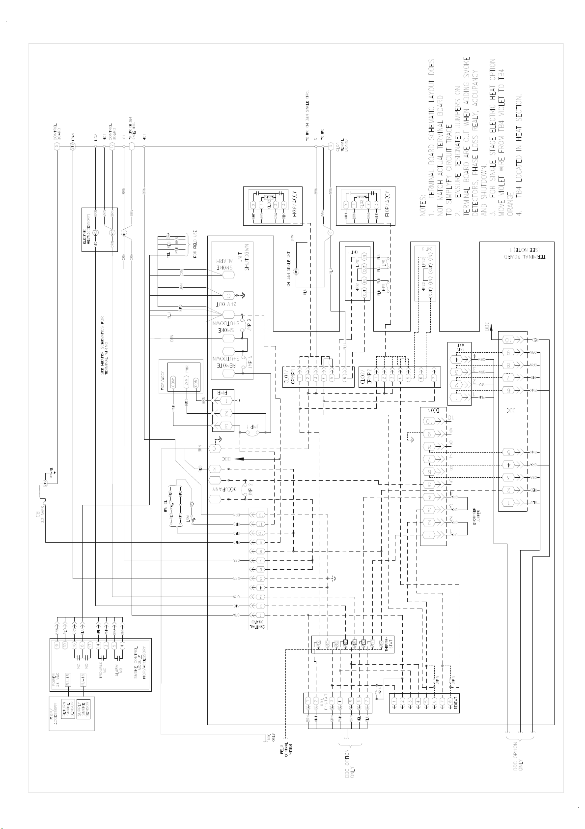
Typical Control Schematic 50TCMA Series
Page 27
Page 28
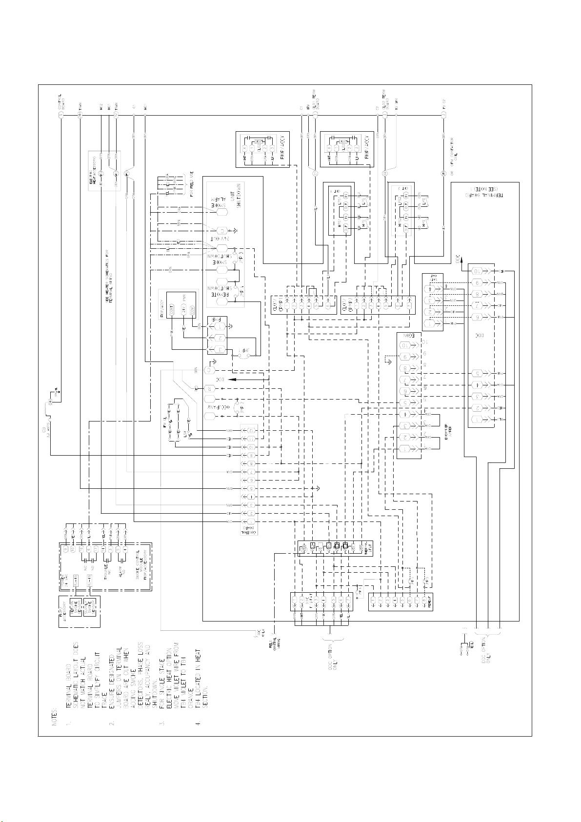
Typical Control Schematic 50TCMD Series
Page 28
Page 29
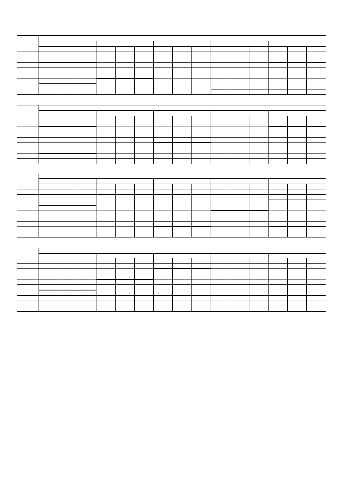
Table 5 - Fan Performance
1.2
1.4
1.6
1.8
2.0
Unit 50TCM - D08 - 7.5 Tons - 400V - 50Hz
Available External Static Pressure (in. w g)
Page 29
Unit 50TCM - A07 - 6 Tons - 400V - 50Hz
Air Flow
Rate (CFM)
1800 785 0.48 0.51 885 0.62 0.66 972 0.76 0.82 1051 0.91 0.98 1121 1.07 1.15
1950 833 0.58 0.62 929 0.74 0.79 1013 0.89 0.95 1089 1.05 1.13 1158 1.21 1.31
2100 881 0.70 0.75 973 0.86 0.92 1054 1.03 1.10 1129 1.20 1.29 1197 1.36 1.48
2250 930 0.84 0.90 1019 1.01 1.08 1097 1.18 1.27 1169 1.34 1.46 1236 1.53 1.66
2400 980 0.99 1.06 1065 1.17 1.26 1141 1.36 1.46 1211 1.53 1.66 1276 1.72 1.87
2550 1030 1.17 1.25 1112 1.36 1.46 1185 1.54 1.67 1253 1.73 1.88 1317 1.93 2.10
2700 1081 1.34 1.46 1159 1.54 1.67 1231 1.75 1.90 1297 1.95 2.12 1358 2.16 2.35
2850 1133 1.56 1.69 1207 1.77
Unit 50TCM - A07 - 6 Tons - 400V - 50Hz (Continued)
Air Flow
Rate (CFM)
1800 1188 1.22 1.33 1249 1.39 1.51 1307 1.57 1.70 1363 1.75 1.90 1373 1.93 2.10
1950 1223 1.37 1.49 1284 1.55 1.68 1342 1.73 1.88 1396 1.92 2.09
2100 1261 1.54 1.67 1320 1.72 1.87 1376 1.92 2.08 1431 2.11 2.29
2250 1298 1.72 1.87 1356 1.92 2.08 1412 2.11 2.29
2400 1337 1.92 2.09 1394 2.13 2.31
2550 1376 2.15 2.33
2700
2850
Air Flow
Rate (CFM)
2250 511 0.44 0.48 591 0.61 0.66 660 0.80 0.86 722 1. 00 1.07 779 0.82 0.89
2438 540 0.54 0.58 616 0.71 0.77 683 0.91 0.97 743 1. 12 1.20 799 0.94 1.02
2625 569 0.64
2813 599 0.76 0.81 669 0.96 1.03 731 1.17 1.25 788 1. 38 1.49 841 1.19 1.30
3000 630 0.89 0.95 696 1.10 1.18 756 1.31 1.42 811 1.54 1.67 863 1.34 1.46
3188 661 1.03 1.11 724 1.26 1.35 782 1.48 1.60 836 1.72 1.86 886 1.50 1.63
3375 692 1.20 1.29 753 1.42 1.54 808 1.66 1.80 861 1.91 2.08 910 1.67 1.82
3563 723 1.38 1.49 782 1.61 1.75 836 1.87 2.03 887 2.12 2.30
3750 755 1.57 1.70 811 1.82 1.98 864 2.09 2.27
RPM KWI BHP RPM KWI BHP RPM KWI BHP RPM KWI BHP RPM KWI BHP
RPM KWI BHP RPM KWI BHP RPM KWI BHP RPM KWI BHP RPM KWI BHP
RPM KWI BHP RPM KWI BHP RPM KWI BHP RPM KWI BHP RPM KWI BHP
0.2 0.4 0.6 0.8 1.0
1.2
0.2 0.4 0.6 0.8 1.0
0.68 642 0.83 0.89 706 1. 03 1.11 765 1.24 1.34 819 1.06 1.15
1.4 1.6 1.8 2.0
Available External Static Pressure (in. w g)
1.92 1276 1.98 2.15
Available External Static Pressure (in. w g)
Unit 50TCM - D08 - 7.5 Tons - 400V - 50Hz (Continued)
Air Flow
Rate (CFM)
2250 832 1.42 1.54 882 1.65 1.79 928 1.90 2.06
2438 851 1.55 1.68 899 1.79 1.94
2625 870
2813 890 1.86 2.02
3000 912 2.04 2.21
3188
3375
3563
3750
Legend:
Normal Font - Field Installed Drive Package
Bold Font - Standard Drive Package + Standard Motor.
Italics Font - Medium Drive Package + Medium Static Motor.
RPM - Rev olutions Per Minute
KWI - Kilo Watts Input to Motor
BHP - Brake Horsepower Input to Fan
CFM - Cubic Feet per Minute
in.wg - Inch W ater Gage
Notes:
1. Do not adjust motor rpm such that motor m aximum bhp and/or watts is exceeded at the maximum operatin cfm.
2. Static Pressure (i.e Filters) must be added to external static pressure before entering fan performance table.
3. Interpolation is permissible. Do not extrapolate.
4. Fan performance is based on wet coils, clean filters and casing loses.
5. Extensive motor and drive testing on these units ensures that the full brake horsepower and watts range of the motor can be utilized with confidence. Using your fan motors up to the watts
or bhp rating shown will not result in nuisance tripping or premature motor failure. Unit warranty will not be affected.
6. Bold data shows the range of air flow rate for unit management system, other rpms require field-supplied drive.
7. Use of field-supplied motor may affect wiring size. Contact your Carrier representative for details.
8. Conversion - Bhp to KWI
RPM KWI BHP RPM KWI BHP RPM KWI BHP RPM KWI BHP RPM KWI BHP
1.69 1.84 918 1.94 2.11
KWI=
Bhp X 0.746
Motor efficiency
Available External Static Pressure (in. w g)
Page 30
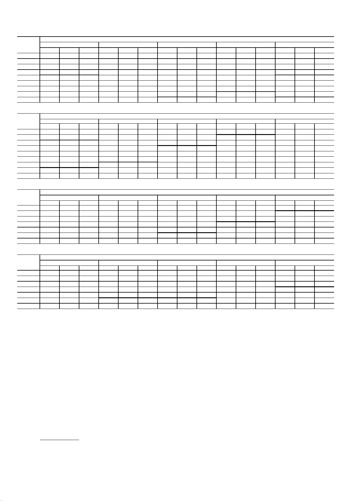
Table 5 - Fan Performance (Continued)
RPM K WI BHP RPM KWI BHP RPM KWI BHP RPM KWI BHP RPM KWI BHP
RPM K WI BHP RPM KWI BHP RPM KWI BHP RPM KWI BHP RPM KWI BHP
Legend:
1.2
1.4
1.6
1.8
2.0
Page 30
Unit 50TCM - D09 - 8.5 Tons - 400V - 50Hz
Air Flow
Rate (CFM)
2550 477 0.42 0.45 556 0.56 0.60 624 0.69 0.74 685 0. 83 0.89 742 0.95 1.03
2763 503 0.51 0.54 578 0.65 0.70 644 0.80 0.86 704 0. 95 1.01 759 1.09 1.18
2975 529 0.60 0.65 601 0.77 0.83 665 0.93 0.99 724 1. 08 1.16 777 1.23 1.34
3188 556 0.72 0.77 625 0.90 0.96 687 1.06 1.14 744 1. 21 1.32 796 1.39 1.50
3400 583 0.86 0.92 650 1.03 1.11 710 1.21 1.30 765 1. 38 1.49 816 1.56 1.69
3613 611 1.00 1.08 675 1.19 1.27 733 1.38 1.48 787 1. 55 1.68 836 1.74 1.89
3825 639 1.16 1.24 701 1.36 1.46 757 1.55 1.68 808 1. 74 1.89 857 1.94 2.11
3950 668 1.34 1.44 727 1.56
4250 696 1.54 1.65 753 1.74 1.89 806 1.96 2.13 855 2.18 2.37
Unit 50TCM - D09 - 8.5 Tons - 400V - 50Hz (Continued)
Air Flow
Rate (CFM)
2550 794 1.10 1.19 842 1.24 1.35 888 1.39 1.50 932 1.53 1.66
2763 810 1.23 1.34 858 1.39 1.50 903 1.54 1.67
2975 827 1.39 1.50 874 1.55 1.68 919 1.71 1.86
3188 845 1.56 1.69 891 1.72 1.87
3400 864 1.73 1.88 909 1.92 2.08
3613 883 1.93 2.10 928 2.13 2.31
3825 903 2.15 2.33
3950
4250
Unit 50TCM - D12 - 10 Tons - 400V - 50Hz
Air Flow
Rate (CFM)
3000 556 0.66 0.72 623 0.81 0.88 684 0.96 1.05 738 1. 12 1.22 789 1.28 1.39
3250 590 0.80 0.87 655 0.97 1.06 713 1.14 1.24 766 1. 31 1.42 815 1.48 1.61
3500 625 0.97 1.06 687 1.15 1.25 742 1.34 1.45 794 1. 52 1.65 841 1.70 1.85
3750 661 1.18 1.28 719 1.37 1.49 773 1.56 1.69 822 1. 75 1.90 869 1.96 2.12
4000 697 1.39 1.51 753 1.60 1.74 804 1.81 1.97 852 2. 02 2.19 897 2.23 2.42
4250 733 1.64 1.78 787 1.84 2.00 836 2.09 2.27 883 2. 31 2.51 926 2.52 2.74
4500 770 1.91 2.08 821 2.16 2.34 869 2.39 2.60 914 2. 62 2.85 956 2.86 3.10
RPM KWI BHP RPM KWI BHP RPM KWI BHP RPM KWI BHP RPM KWI BHP
RPM KWI BHP RPM KWI BHP RPM KWI BHP RPM KWI BHP RPM KWI BHP
0.2 0.4 0.6 0.8
0.2 0.4 0.6 0.8 1.0
Available External Static Pressure (in. w g)
1.0
1.67 781 1.74 1.89 832 1.95 2.12 879 2.17 2.35
Available External Static Pressure (in. w g)
Available External Static Pressure (in. w g)
Unit 50TCM - D12 - 10 Tons - 400V - 50Hz (Continued)
Air Flow
Rate (CFM)
3000 836 1.44 1.56 881 1.59 1.73 923 1.75 1.90 963 1. 91 2.08 1001 2.08 2.26
3250 861 1.65 1.79 904 1.81 1.97 945 1.99 2.16 985 2. 16 2.34 1023 2.33 2.53
3500 886 1.88 2.05 929 2.07 2.24 969 2.25 2.44 1008 2.43 2.64 1045 2.61 2.84
3750 912 2.15 2.33 954 2.34 2.54 994 2.53 2.75 1031 2.74 2.97 1068 2.93 3.18
4000 940 2.43 2.64 980 2.64 2.87 1019 2.85 3.09 1056 3.06 3.32 1092 3.26 3.54
4250 968 2.75 2.98 1007 2.97 3.22 1045 3.19 3.47 1081 3.40 3.70 1117 3.63 3.94
4500 996 3.09 3.36 1035 3.32 3.61 1072 3.56 3.86 1108 3.79 4.11
Normal Font - Field Installed Drive Package
Bold Font - Standard Drive Package + Standard Motor.
Italics Font - Medium Drive Package + Medium Static Motor.
RPM - Rev olutions Per Minute
KWI - Kilo Watts Input to Motor
BHP - Brake Horsepower Input to Fan
CFM - Cubic Feet per Minute
in.wg - Inch W ater Gage
Notes:
1. Do not adjust motor rpm such that motor m aximum bhp and/or watts is exceeded at the maximum operatin cfm.
2. Static Pressure (i.e Filters) must be added to external static pressure before entering fan performance table.
3. Interpolation is permissible. Do not extrapolate.
4. Fan performance is based on wet coils, clean filters and casing loses.
5. Extensive motor and drive testing on these units ensures that the full brake horsepower and watts range of the motor can be utilized with confidence. Using your fan motors up to the watts
or bhp rating shown will not result in nuisance tripping or premature motor failure. Unit warranty will not be affected.
6. Bold data shows the range of air flow rate for unit management system, other rpms require field-supplied drive.
7. Use of field-supplied motor may affect wiring size. Contact your Carrier representative for details.
8. Conversion - Bhp to KWI
KWI=
Motor efficiency
1.2 1.4
Bhp X 0.746
Available External Static Pressure (in. w g)
1.6 1.8 2.0
Page 31
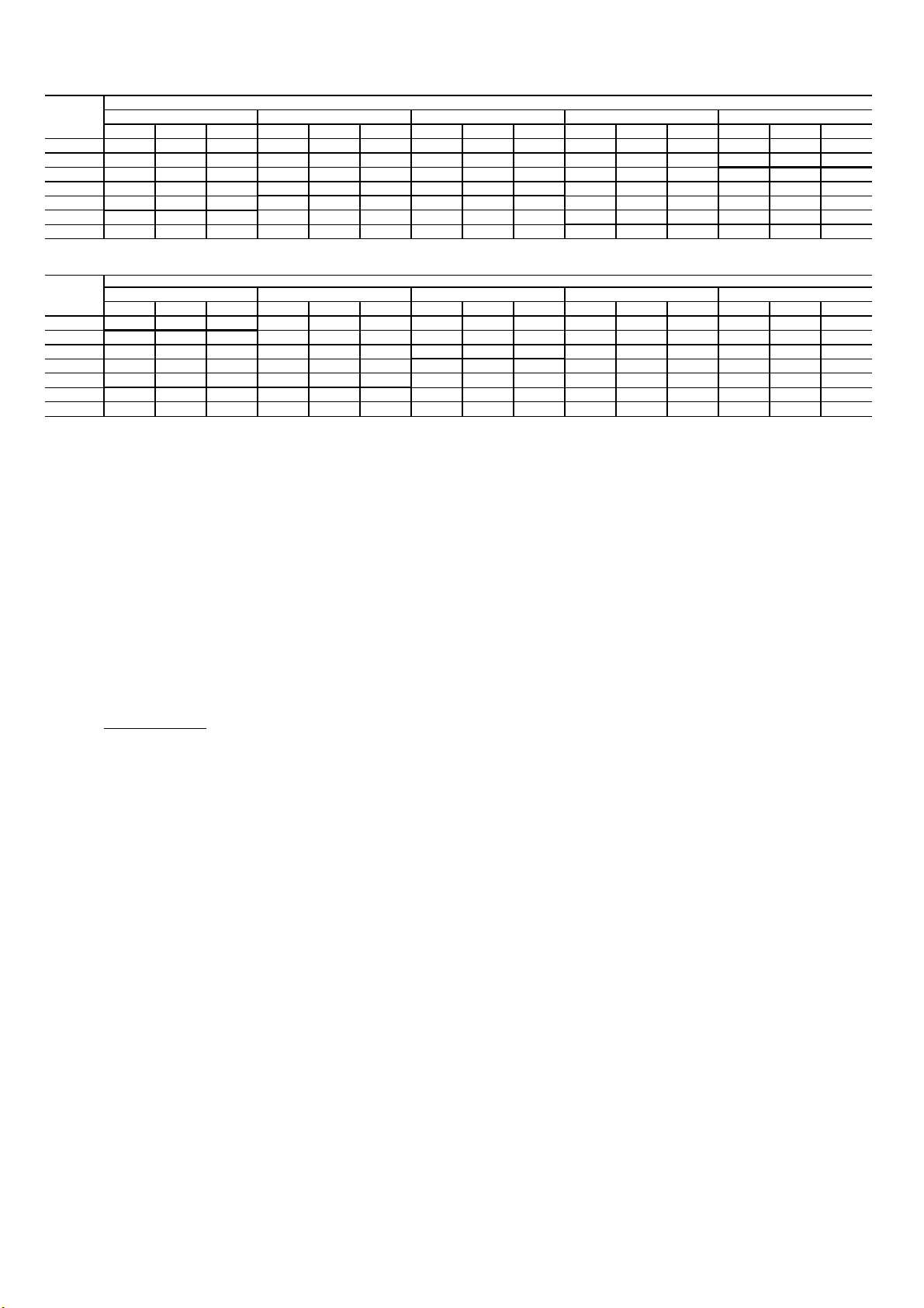
Table 5 - Fan Performance (Continued)
5. Extensive motor and drive testing on these units ensures that the full brake horsepower and watts range of the motor can be utilized with confidence. Using your fan motors up to the watts
Available External Static Pressure (in. w g)
Unit 50TCM - D14 - 12.5 Tons - 400V - 50Hz (Continued)
Page 31
Unit 50TCM - D14 - 12.5 Tons - 400V - 50Hz
Air Flow
Rate (CFM)
3700 621 0.98 1.06 679 1.15 1.25 734 1.33 1.44 786 1. 51 1.64 837 1.70 1.84
4063 665 1.21 1.32 717 1.39 1.51 769 1.58 1.72 818 1. 78 1.94 866 1.98 2.15
4375 706 1.48 1.61 757 1.68 1.82 805 1.88 2.04 852 2. 09 2.27 897 2.31 2.50
4688 749 1.79 1.95 797 2.00 2.17 843 2.21 2.40 887 2.44 2.65 930 2.67 2.89
5000 793 2.14 2.33 838 2.37 2.58 881 2.60 2.82 923 2.83 3.07 965 3.06 3.33
5313 837 2.55 2.77 880 2.78 3.02 921 3.03 3.29 961 3.26 3.54 1000 3.52 3.82
5700 882 3.00 3.25 922 3.24 3.52 961 3.49 3.79
Air Flow
Rate (CFM)
3700 885 1.89 2.05 932 2.09 2.27 978 2.30 2.49 1022 2.50 2.72
4063 912 2.19 2.38 957 2.40 2.61 1001 2.61 2.83 1043 2.83 3.07
4375 941 2.52 2.74 984 2.74 2.98 1026 2.97 3.22
4688 972 2.89 3.14 1013 3.12 3.39
5000 1005 3.31 3.59 1044 3.55 3.85
5313
5700
Legend:
Normal Font - Field Installed Drive Package
Bold Font - Standard Drive Package + Standard Motor.
Italics Font - Medium Drive Package + Medium Static Motor.
RPM - Rev olutions Per Minute
KWI - Kilo Watts Input to Motor
BHP - Brake Horsepower Input to Fan
CFM - Cubic Feet per Minute
in.wg - Inch W ater Gage
RPM KWI BHP RPM KWI BHP RPM KWI BHP RPM KWI BHP RPM KWI BHP
RPM KWI BHP RPM KWI BHP RPM KWI BHP RPM KWI BHP
0.2 0.4 1.0
1.2
1.4 1.6 1.8 2.0
Available External Static Pressure (in. w g)
0.6 0.8
RPM KWI BHP
Notes:
1. Do not adjust motor rpm such that motor m aximum bhp and/or watts is exceeded at the maximum operatin cfm.
2. Static Pressure (i.e Filters) must be added to external static pressure before entering fan performance table.
3. Interpolation is permissible. Do not extrapolate.
4. Fan performance is based on wet coils, clean filters and casing loses.
or bhp rating shown will not result in nuisance tripping or premature motor failure. Unit warranty will not be affected.
6. Bold data shows the range of air flow rate for unit management system, other rpms require field-supplied drive.
7. Use of field-supplied motor may affect wiring size. Contact your Carrier representative for details.
8. Conversion - Bhp to KWI
KWI=
Bhp X 0.746
Motor efficiency
Page 32
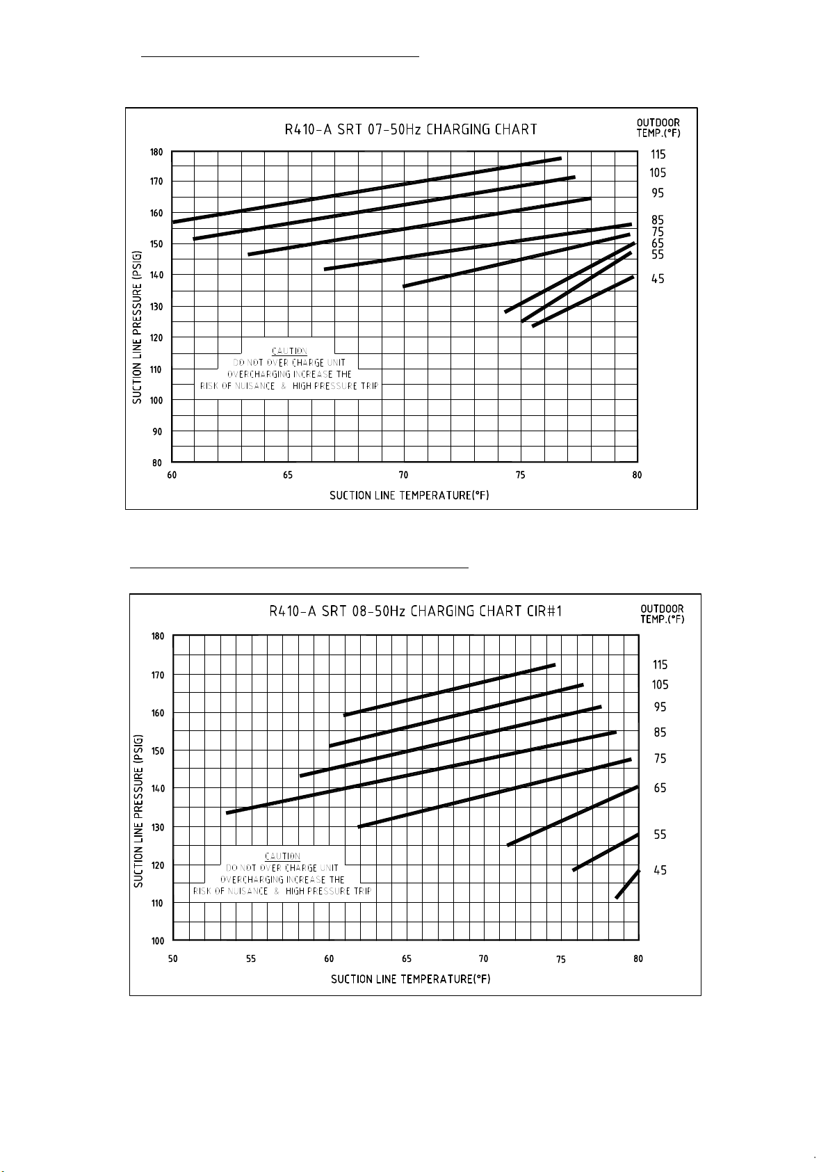
Charging Chart 400V-50Hz 50TCMA07
Page 32
Charging Chart 400V-50Hz 50TCMD08 CIR # 1
Page 33
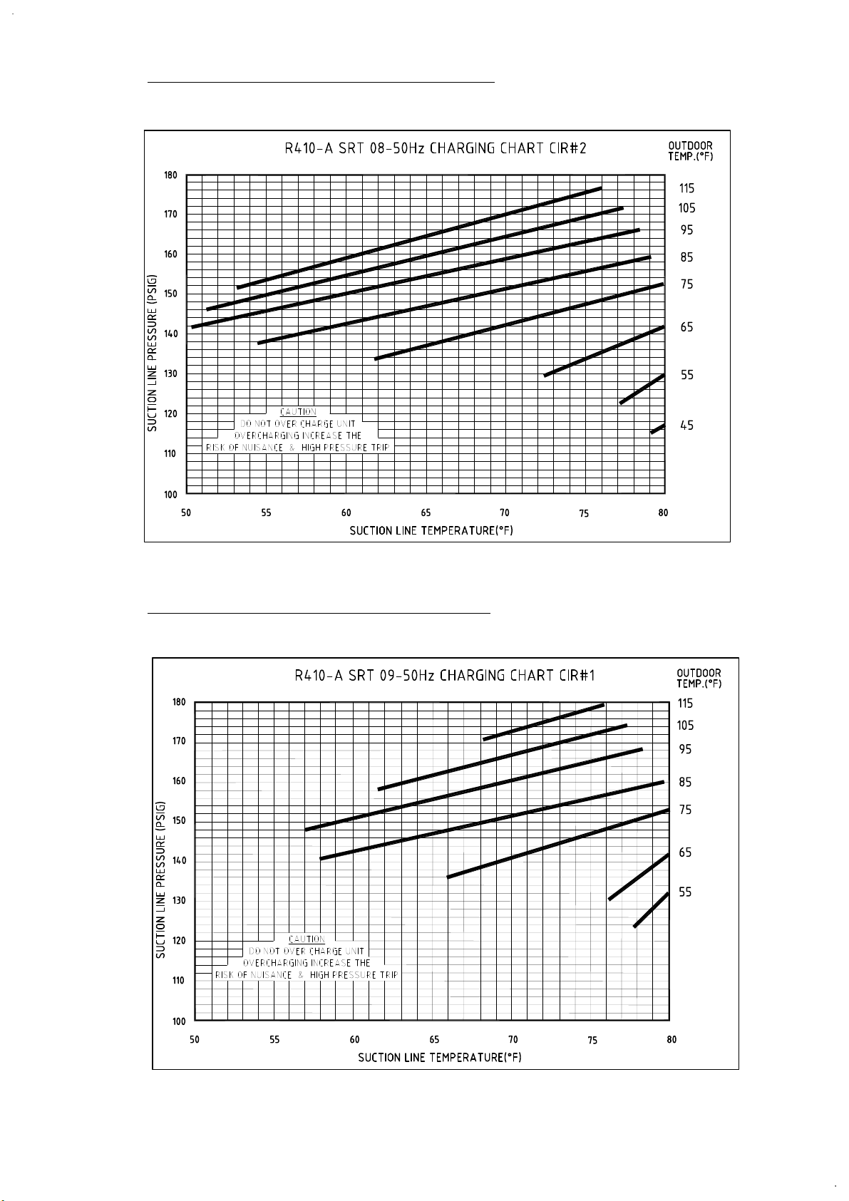
Charging Chart 400V-50Hz 50TCMD08 CIR # 2
Page 33
Charging Chart 400V-50Hz 50TCMD09 CIR # 1
Page 34
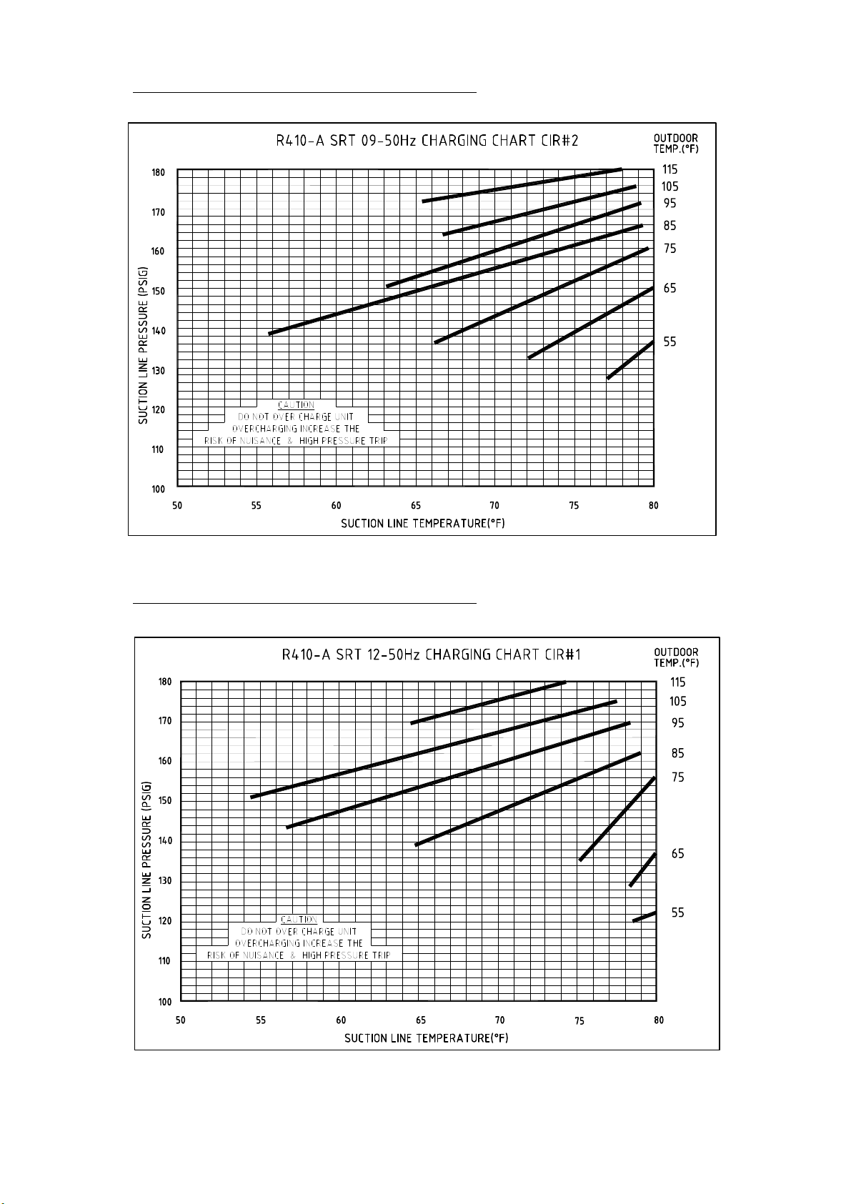
Charging Chart 400V-50Hz 50TCMD09 CIR # 2
Page 34
Charging Chart 400V-50Hz 50TCMD12 CIR # 1
Page 35
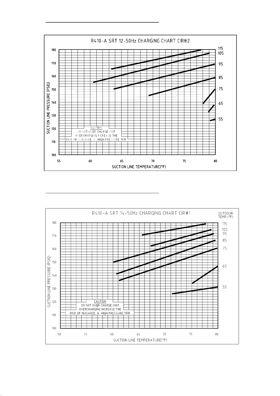
Charging Chart 400V-50Hz 50TCMD12 CIR # 2
Page 35
Charging Chart 400V-50Hz 50TCMD14 CIR # 1
Page 36
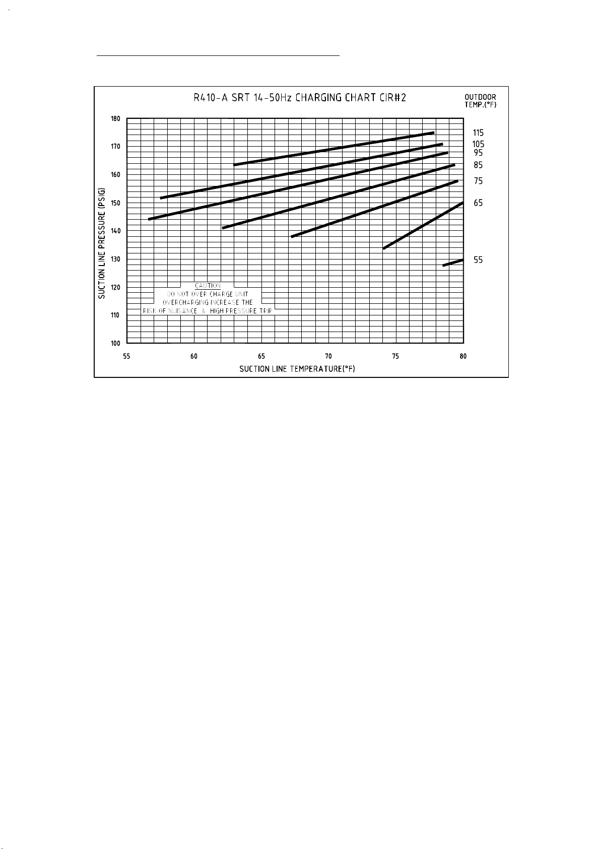
Charging Chart 400V-50Hz 50TCMD14 CIR # 2
Page 36
Page 37

ATTENTION INSTALLERS AND SERVICE TECHNICIANS!
Page 37
R-410A Refrigerant Quick Reference Guide
• R-410A refrigerant operates at 50-70 percent higher pressures than R-22. Be sure that servicing equipment
and replacement components are designed to operate with R-410A refrigerant.
• R-410A refrigerant cylinders are rose colored.
• Recovery cylinder service pressure rating must be 400 psig, DOT 4BA400 or DOT BW400.
• R-410A refrigerant systems should be charged with liquid refrigerant. Use a commercial type metering
device in the manifold hose when charging into suction line with compressor operating.
• Manifold sets should be 700 psig high side and 180 psig low side with 550 psig low-side retard.
• Use hoses with 700 psig service pressure rating.
• Leak detectors should be designed to detect HFC refrigerant.
• R-410A refrigerant, as with other HFCs, is only compatible with POE oils.
• Vacuum pumps will not remove moisture from oil.
• Do not use liquid-line filter driers with rated working pressures less than 600 psig.
• Do not leave R-410A refrigerant suction line filter driers in line longer than 72 hours.
• Do not install a suction-line filter drier in liquid-line.
• POE oils absorb moisture rapidly. Do not expose oil to atmosphere.
• POE oils may cause damage to certain plastics and roofing materials.
• Wrap all filter driers and service valves with wet cloth when brazing.
• A factory-approved liquid-line filter drier is required on every unit.
• Do NOT use an R-22 expansion device.
• If indoor unit is equipped with an R-22 expansion device, it must be changed to a hard-shutoff R-410A
refrigerant expansion device.
• Never open system to atmosphere while it is under a vacuum.
• When system must be opened for service, recover refrigerant, evacuate then break vacuum with dry
nitrogen and replace filter driers. Evacuate to 500 microns prior to recharging.
• All indoor coils must be installed with a hard-shutoff R-410A refrigerant expansion metering device.
• Do not vent R-410A refrigerant into the atmosphere.
• Do not use capillary tube coils.
• Observe all warnings, cautions, and bold text.
Page 38
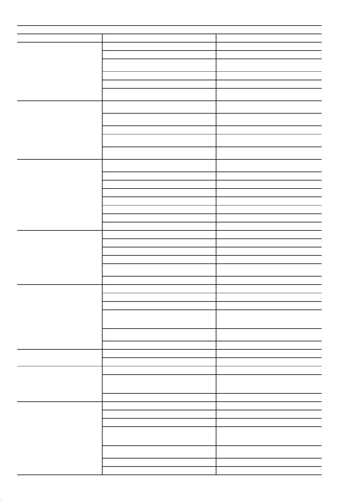
Troubleshooting Guide
Thermostat setting too high.
Lower thermostat setting below room
Faulty wiring or loose connections in compressor
Check wiring and repair or replace.
Compressor motor burned out, seized, or internal over-
Determine cause. Replace compressor.
Defective overload. Determine cause and replace.
Compressor locked out Determine cause for safety trip and reset lockout.
One leg of 3-phase power dead.
Replace fuse or reset circuit breaker.
Refrigerant overcharge or undercharge.
Recover refrigerant, evacuate system, and
Restriction in refrigerant system. Locate restriction and remove.
Dirty air filter. Replace filter.
Unit undersized for load. Decrease load or increase unit size.
Thermostat set too low. Reset thermostat.
Low refrigerant charge. Locate leak, repair, and recharge.
Air in system.
Recover refrigerant, evacuate system, and
Condenser coil dirty or restricted. Clean coil or remove restriction.
Dirty drier filter. Replace filter.
Dirty condenser coil. Clean coil.
Refrigerant overcharged. Recover excess refrigerant.
Faulty TXV.
1. Check TXV bulb mounting and secure tightly to
Air in system.
Recover refrigerant, evacuate system, and
Condenser air restricted or air short-cycling. Determine cause and correct.
Low refrigerant charge. Check for leaks, repair, and recharge.
Restriction in liquid tube. Remove restriction.
High heat load. Check for source and eliminate.
Faulty TXV.
1. Check TXV bulb mounting and secure tightly to
Refrigerant overcharged. Recover excess refrigerant.
Dirty air filter. Replace filter.
Low refrigerant charge. Check for leaks, repair, and recharge.
Metering device or low side restricted. Remove source of restriction.
Faulty TXV.
1. Check TXV bulb mounting and secure tightly to
Temperature too low in conditioned area. Reset thermostat.
Field-installed filter drier restricted. Replace.
Compressor cycles (other than normally
Page 38
Cooling Service Analysis
PROBLEM CAUSE REMEDY
Compressor and condenser fan will not
start.
Compressor will not start but condenser
fan runs.
Power failure. Call power company.
Fuse blown or circuit breaker tripped. Replace fuse or reset circuit breaker.
Defective thermostat, contactor, transformer, or
control relay.
Insufficient line voltage. Determine cause and correct.
Incorrect or faulty wiring. Check wiring diagram and rewire correctly.
circuit.
load open.
Replace component.
temperature.
Determine cause.
satisfying thermostat).
Compressor operates continuously.
Excessive head pressure.
recharge to nameplate.
Defective compressor. Replace and determine cause.
Insufficient line voltage. Determine cause and correct.
Blocked condenser. Determine cause and correct.
Defective overload. Determine cause and replace.
Defective thermostat. Replace thermostat.
Faulty condenser-fan motor. Replace.
recharge.
suction line.
2. Replace TXV if stuck open or closed.
recharge.
Head pressure too low.
Excessive suction pressure.
Suction pressure too low.
Insufficient evaporator airflow. Increase air quantity. Check filter and replace if
suction line.
2. Replace TXV if stuck open or closed.
suction line.
2. Replace TXV if stuck open or closed.
necessary.
Page 39
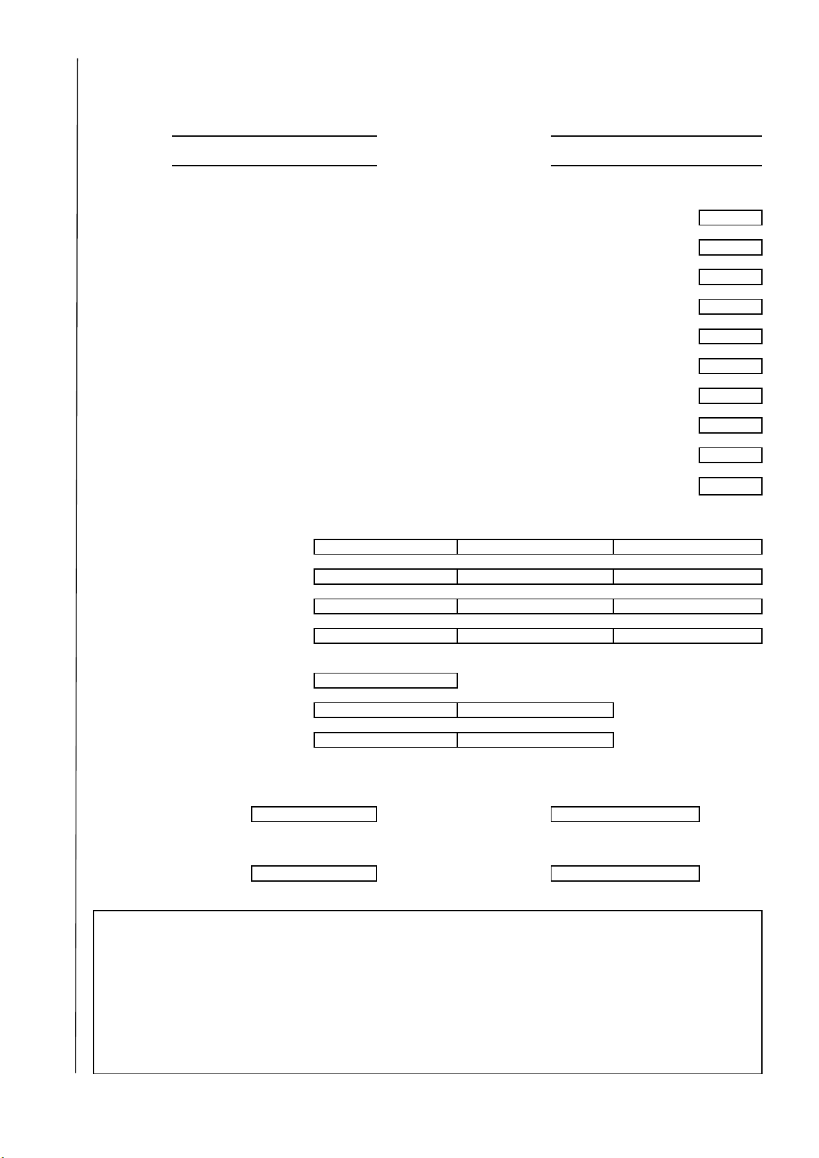
START-UP CHECKLIST
MODEL NO: DATE:
SERIAL NO: TECHNICIAN:
3) CONDENSATE CONNECTION IS INSTALLED PER INSTALLATION INSTRUCTION.
5) POWER WIRES HAVE BEEN SIZED AND INSTALLED PROPERLY TO THE UNIT.
6) CONTROL WIRING CONNECTIONS HAVE BEEN INSTALLED PROPERLY.
7) CHECK ALL WIRING TERMINALS HAVE BEEN TIGHTENED PROPERLY.
(Remove and Store in Job File)
II. PRE-START-UP (Insert checkmark in box as each item is completed)
I. PRELIMINARY INFORMATION
2) VERIFY THAT UNIT INSTALLATION IS LEVEL.
1) ALL PACKING MATERIALS HAVE BEEN REMOVED FROM THE UNIT.
(L2):
III. START - UP
ELECTRICAL:
8) ENERGIZE CRANKCASE HEATERS FOR 12 HOURS.
(L3):
(L3):
(L2):
TEMPERATURES:
(BOTH CIRCUITS OPERATING)
COMPRESSOR - 1 AMPS:
INDOOR FAN AMPS:
(L1):
(L1):
INDOOR SECTION ENTERING AIR:
INDOOR SECTION LEAVING AIR:
: DB
: DB
:WB
:WB
PRESSURES:
CIRCUIT - 1
REFRIGERANT SUCTION
REFRIGERANT SUCTION
REFRIGERANT DISCHARGE
REFRIGERANT DISCHARGE
:PSIG
:PSIG
:PSIG
:PSIG
Page 39
4) UNIT GROUNDING WIRE HAS BEEN CONNECTED.
9) CORRECT FAN ROTATION HAS BEEN CONFIRMED.
10) SEALED ALL POWER AND CONTROL WIRES ENTRY INTO THE UNIT AND INSIDE THE BOX
(Tear Along This Line)
SUPPLY VOLTAGE:
COMPRESSOR - 2 AMPS:
OUTDOOR AIR:
(L1 - L2):
(L1):
CIRCUIT - 2
(L2 - L3):
(L2):
: DB
(L3 - L1):
(L3):
VERIFY REFRIGERANT CHARGE USING CHARGING CHART.
Notes:
Page 40

Page 40
Manufacturer reserves the rights to discontinue or change at any time, specifications or designs without notice and without incurring any obligations.
Supersedes Version: 50TCM-IOM01 Catalog Number: 50TCM-IOM02
Effective Date: 12-07-2016 Phase: 50Hz
 Loading...