

Carrier 50TC-D17, 50TC-E20, 50TC-E17, 50TC-D20, 50TC-D24 Service And Maintenance Instructions
...
50TC*17- 30
Nominal 15 to 27.5 Tons
With Puron ® (R-410A) Refrigerant
Service and Maintenance Instructions
TABLE OF CONTENTS
TABLE OF CONTENTS 1.........................
SAFETY CONSIDERATIONS 1....................
UNIT ARRANGEMENT AND ACCESS 3...........
SUPPLY FAN (BLOWER) SECTION 4..............
STAGED AIR VOLUME (SAV) CONTROL: 2−SPEED
FAN WITH VARIABLE FREQUENCY DRIVE (VFD) 6
ADDITIONAL VFD INSTALLATION AND
TROUBLESHOOTING 7..........................
CONDENSER COIL SERVICE 8...................
EVAPORATOR COILS 10.........................
HIMIDI−MIZER DEHUMIDIFICATION SYSTEM 12
THERMOSTATIC EXPANSION VALVE (TXV) 17....
PURON (R−410A) REFRIGERANT 19.............
COOLING CHARGING CHARTS 20................
COMPRESSORS 24..............................
TROUBLESHOOTING THE COOLING SYSTEM 26..
CONVENIENCE OUTLETS 27....................
SMOKE DETECTORS 28.........................
INDICATORS 34................................
PROTECTIVE DEVICES 35.......................
PREMIERLINK™ CONTROL 36...................
RTU−OPEN CONTROL SYSTEM 38................
ECONOMI$ER SYSTEMS 40......................
PRE−START−UP/START−UP 49....................
START−UP, PREMIERLINK™ CONTROLS 50.......
START−UP, RTU−OPEN CONTROLS 51............
FASTENER TORQUE VALUES 51.................
APPENDIX I. MODEL NO. NOMENCLATURE 52...
APPENDIX II. PHYSICAL DATA 53................
APPENDIX III. FAN PERFORMANCE 61...........
APPENDIX IV. WIRING DIAGRAMS 67............
APPENDIX V. MOTORMASTER SENSOR
LOCATIONS 80.................................
UNIT START-UP CHECKLIST 81..................
SAFETY CONSIDERATIONS
Installation and servicing of air-conditioning equipment
can be hazardous due to system pressure and electrical
components. Only trained and qualified service personnel
should install, repair, or service air-conditioning
equipment. Untrained personnel can perform the basic
maintenance functions of replacing filters. Trained service
personnel should perform all other operations.
When working on air-conditioning equipment, observe
precautions in the literature, tags and labels attached to
the unit, and other safety precautions that may apply.
Follow all safety codes. Wear safety glasses and work
gloves. Use quenching cloth for unbrazing operations.
Have fire extinguishers available for all brazing
operations.
Follow all safety codes. Consult local building codes and
National Electrical Code (NEC) for special requirements.
Recognize safety information. This is the safety−alert
symbol . When you see this symbol on the unit and in
instructions or manuals, be aware of the potential for
physical injury hazards.
Understand the signal words DANGER, WARNING, and
CAUTION. These words are used with the safety−alert
symbol. DANGER identifies a hazardous situation which,
if not avoided, will result in death or severe personal
injury. WARNING indicates a hazardous situation which,
if not avoided, could result in death or personal injury.
CAUTION indicates a hazardous situation which, if not
avoided, could result in minor to moderate injury or
product and property damage. NOTICE is used to address
practices not related to physical injury. NOTE is used to
highlight suggestions which will result in enhanced
installation, reliability, or operation.

!
CAUTION
!
CAUTION
CUT HAZARD
Failure to follow this caution may result in personal
injury.
Sheet metal parts may have sharp edges or burrs. Use
care and wear appropriate protective clothing, safety
glasses and gloves when handling parts and servicing
air conditioning equipment.
!
WARNING
FIRE, EXPLOSION HAZARD
Failure to follow this
warning could result in
death, personal personal
injury and/or property
damage.
Never use air or gases containing oxygen for leak
testing or for operating refrigerant compressors.
Pressurized mixtures of air or gases containing
oxygen can lead to an explosion.
!
WARNING
FIRE, EXPLOSION HAZARD
Failure to follow this
warning could result in
death, personal personal
injury and/or property
damage.
Never use non−certified refrigerants in this product.
Non−certified refrigerant could contain contaminant
that could lead to unsafe operating conditions. Use
ONLY refrigerants that conform to AHRI Standard
700.
!
WARNING
UNIT OPERATION AND SAFETY HAZARD
Failure to follow this warning could cause personal
injury, death and/or equipment damage.
This system uses Puron refrigerant which has
higher pressures than R−22 and other refrigerants. No
other refrigerant may be used in this system. Gauge
set, hoses, and recovery system must be designed to
handle Puron refrigerant. If unsure about equipment,
consult the equipment manufacturer.
UNIT DAMAGE HAZARD
Failure to follow this caution can result in reduced
unit performance or unit shutdown.
High velocity water from a pressure washer, garden
hose, or compressed air should never be used to clean
a coil. The force of the water or air jet will bend the
fin edges and increase airside pressure drop.
NOTICE
OPERATIONAL TEST ALERT
Failure to follow this ALERT could result in an
unnecessary evacuation of the facility.
Pressing the controller’s test/reset switch for longer
than seven seconds will put the duct detector into the
alarm state and activate all automatic alarm responses.
!
WARNING
ELECTRICAL SHOCK HAZARD
Failure to follow this warning could cause personal
injury or death.
Before performing service or maintenance operations
on the fan system, shut off all unit power and
Lockout/Tagout the unit disconnect switch. DO NOT
reach into the fan section with power still applied to
the unit.
!
WARNING
ELECTRICAL OPERATION HAZARD
Failure to follow this warning could result in personal
injury or death.
Units with convenience outlet circuits may use
multiple disconnects. Check the convenience outlet
for power status before opening the unit for service.
Locate its disconnect switch, if appropriate, and open
it. Lockout/Tagout this switch if necessary.
IMPORTANT: Lockout/Tagout is a term used when
electrical power switches are physically locked,
preventing power to the unit. A placard is placed on
the power switch, alerting personnel that the power is
disconnected.
2

UNIT ARRANGEMENT AND
ACCESS
General
Fig. 1 and Fig. 2 show general unit arrangement and
access locations.
SUPPLY FAN
OUTDOOR AIR
HOOD
DISCONNECT
CONVENIENCE
OUTLET
CONTROL BOX
ACCESS PANEL
HEATING SECTION
RETURN AIR
FILTER AND
INDOOR COIL
ACCESS PANEL
GAS SECTION
ACCESS PANEL
Fig. 1 − Access Panels and Components, Front
OUTDOOR
FANS/MOTORS
COMPRESSOR
(CIRCUIT A)
CONDENSER
COIL
(CIRCUIT A)
C12560
Seasonal Maintenance
These items should be checked at the beginning of each
season (or more often if local conditions and usage
patterns dictate):
Air Conditioning
Condenser fan motor mounting bolts tightness
Compressor mounting bolts
Condenser fan blade positioning
Control box cleanliness and wiring condition
Wire terminal tightness
Refrigerant charge level
Evaporator coil cleaning
Evaporator blower motor amperage
Heating
Heat exchanger flue passageways cleanliness
Gas burner condition
Gas manifold pressure
Heating temperature rise
CONDENSER COIL
CIRCUIT A
CONDENSER COIL
CIRCUIT B
COMPRESSOR
CIRCUIT B
C09505
Fig. 2 − Typical Access Panel Locations, Rear
Routine Maintenance
These items should be part of a routine maintenance
program, to be checked every month or two, until a
specific schedule for each can be identified for this
installation:
Quarterly Inspection (and 30 days after initial start)
The 50TC units should be inspected and serviced every
three months.
Return air filter replacement
Outdoor hood inlet filters cleaned
Belt tension checked
Belt condition checked
Pulley alignment checked
Fan shaft bearing locking collar tightness checked
Condenser coil cleanliness checked
Condensate drain checked
Economizer or Outside Air Damper
Inlet filters condition
Check damper travel (economizer)
Check gear and dampers for debris and dirt
Air Filters and Screens
Each unit is equipped with return air filters. If the unit has
an economizer, it will also have an outside air screen. If a
manual outside air damper is added, an inlet air screen
will also be present.
Each of these filters and screens will need to be
periodically replaced or cleaned.
Return Air Filters
Return air filters are disposable fiberglass media type.
Access to the filters is through the small lift−out panel
located on the rear side of the unit, above the
evaporator/return air access panel. (See Fig. 1.)
!
CAUTION
EQUIPMENT DAMAGE HAZARD
Failure to follow this CAUTION can result in
premature wear and damage to equipment.
DO NOT OPERATE THE UNIT WITHOUT THE
RETURN AIR FILTERS IN PLACE. Dirt and
debris on heat exchangers and coils can cause
excessive current use, resulting in motor failure.
3

Removing the Return Air Filters
1. Remove the return air filter and indoor coil access
panel. See Fig. 1.
2. Reach inside and remove filters from the filter rack.
3. Replace these filters as required with similar replacement filters of same size.
4. Re−install the return air filter and indoor coil access
panel.
Outdoor Air Hood
Outside air hood inlet screens are permanent
aluminum−mesh type filters. See Fig. 2. Inspect these
screens for cleanliness. Remove the screens when
cleaning is required. Clean by washing with hot
low−pressure water and soft detergent and replace all
screens before restarting the unit. Observe the flow
direction arrows on the side of each filter frame.
Economizer Inlet Air Screen
This air screen is retained by spring clips under the top
edge of the hood. (See Fig. 3.)
17 1/4
(438 mm)
DIVIDER
OUTSIDE
AIR
HOOD
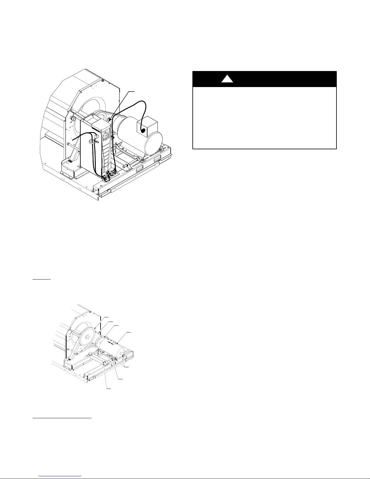
Supply Fan Assembly
The supply fan system consists of two forward−curved
centrifugal blower wheels mounted on a solid blower shaft
that is supported by two greasable pillow block concentric
bearings. A fixed−pitch driven fan pulley is attached to
the fan shaft and an adjustable−pitch driver pulley is
mounted on the motor. The pulleys are connected using a
V−belt. (See Fig. 4.)
Vertical Supply Models
The two fan wheels used on the vertical supply models are
the same: 15″ diameter x 15″ width. This arrangement
provides uniform airflow distribution across the width of
the evaporator coil, electric heater, and into the supply
duct.
Horizontal Supply Models
The horizontal supply models have two different fan
wheel sizes on a single shaft. The front side wheel is 18″
diameter x 15″ wide, while the rear side fan is 15″
diameter x 11″ wide. This arrangement promotes uniform
airflow across the width of the evaporator coil and heater
assembly while using a supply outlet on the rear side of
the unit.
NOTE: This major difference in the fan system design
makes it impossible to field−convert the 50TC unit’s
supply fan outlet configuration.
15” X 15” SUPPLY FANS
CLEANABLE
ALUMINUM
BAROMETRIC
RELIEF
SCREEN
FILTER
CLIP
C06027
Fig. 3 − Inlet Air Screen Installation
Remove screens be removing the screws in the horizontal
clips on the leading edge of the hood. Slide the filters out.
See Fig. 3.
Install the filters by sliding clean or new filters into the
hood side retainers. Once positioned, re−install the
horizontal clips.
SUPPLY FAN (BLOWER) SECTION
!
WARNING
ELECTRICAL SHOCK HAZARD
Failure to follow this warning could cause personal
injury or death.
Before performing service or maintenance operations
on the fan system, shut off all unit power and
Lockout/Tagout the unit disconnect switch. DO NOT
reach into the fan section with power still applied to
the unit.
VERTICAL SUPPLY FANS
15” X 11” SUPPLY FAN
18” X 15” SUPPLY FAN
HORIZONTAL SUPPLY FANS
C12683
Fig. 4 − Supply Fan Arrangements
Belt
Check the belt condition and tension quarterly. Inspect the
belt for signs of cracking, fraying or glazing along the
inside surfaces. Check belt tension by using a spring−force
4

tool, such as Browning’s “Belt Tension Checker” (p/n
1302546 or equivalent tool); tension should be 6−lbs at a
5/8−in. (1.6 cm) deflection when measured at the center
line of the belt span. This point is at the center of the belt
when measuring the distance between the motor shaft and
the blower shaft.
BLOWER
SHAFT
V-BELT
BLOWER 15” X 17”
MOTOR
MOTOR ADJUSTMENT
BOLTS (4)
JACKBOLT LOCKING NUT (2)
MOTOR MOUNTING PLATE
JACKBOLT (2)
BLOWER
18” X 15”
C12260
Fig. 5 − Belt Drive Motor Mounting
NOTE: Without the spring−tension tool, place a straight
edge across the belt surface at the pulleys, then push down
on the belt at mid−span using one finger until a 1/2−in.
(1.3 cm) deflection is reached.
STRAIGHTEDGE
BROWNING BELT
TENSION CHECKER
1/2”
(1.3 cm)
BELT
DEFLECTION
C12093
Fig. 6 − Checking Blower Moter Belt Tension
Adjusting the Belt Tension
Use the following steps to adjust the V−belt tension. See
Fig. 4.
1. Loosen the four motor mounting nuts that attach the
motor to the blower rail.
2. Loosen the two jack bolt locking nuts beneath the
motor mounting plate. Turn the jack bolt locking nut
counterclockwise to loosen.
3. Turn the jack bolts counterclockwise to loosen and
clockwise to tighten.
4. Adjust the V−belt for proper tension.
5. Make sure the fan shaft and motor shaft are parallel
before tightening the motor mount nuts. See Fig. 6.
6. Make adjustments as necessary.
7. Tighten the four motor mounting nuts.
8. Check the V−belt tension. Make adjustments as necessary.
9. Re−tighten the four motor mounting nuts.
10. Tighten both jack bolt locking nuts securely.
Replacing the V−belt
1. Use a belt with same section type or similar size. Do
not substitute a “FHP” or notched type V−belt.
2. Loosen (turn counterclockwise) the motor mounting
plate front bolts and rear bolts. See Fig. 4.
!
CAUTION
EQUIPMENT DAMAGE HAZARD
Failure to follow this CAUTION can result in
premature wear and damage to equipment.
Do not use a screwdriver or pry−bar to place the new
V−belt in the pulley groove. This can cause stress on
the V−belt and the pulley, resulting in premature wear
on the V−belt and damage to the pulley.
3. Loosen (turn counterclockwise) the jack bolt lock
nuts. Loosen (turn counterclockwise) the jack bolts,
relieving the belt tension and allowing easy removal
of the belt by hand.
4. Remove the belt by gently lifting the old belt over
one of the pulleys.
5. Install the new belt by gently sliding the belt over
both pulleys, then tighten (turn clockwise) the jack
bolts, sliding the motor plate away from the fan housing until proper belt tension is achieved.
6. Check the alignment of the pulleys, adjust if necessary. See Fig. 6.
7. Tighten all bolts attaching the motor to the motor
plate.
8. Tighten all jack bolt jam nuts by turning clockwise.
9. Check the tension after a few hours of runtime and
re−adjust as required. See Fig. 5.
Adjustable−Pitch Pulley on Motor
The motor pulley is an adjustable−pitch type that allows a
servicer to implement changes in the fan wheel speed to
match as−installed ductwork systems. The pulley consists
of a fixed flange side that faces the motor (secured to the
motor shaft) and a movable flange side that can be rotated
around the fixed flange side that increases or reduces the
pitch diameter of this driver pulley. (See Fig. 6.)
As the pitch diameter is changed by adjusting the position
of the movable flange, the centerline on this pulley shifts
laterally, along the motor shaft. This creates a requirement
for a realignment of the pulleys after any adjustment of
the movable flange. Also reset the belt tension after each
realignment. The factory settings of the adjustable pulley
is five turns open from full closed.
Check the condition of the motor pulley for signs of wear.
Glazing of the belt contact surfaces and erosion on these
5

surfaces are signs of improper belt tension and/or belt
slippage. Pulley replacement may be necessary.
Changing Fan Speed
1. Shut off the main unit power supply, and use the approved Lockout/Tagout procedures.
2. Loosen the belt by loosening the motor adjustment
bolts as described in the Belt Adjustment section
above.
3. Loosen the movable pulley flange setscrew. (See Fig.
6.)
4. Screw the movable flange toward fixed flange to increase speed and away from fixed flange to decrease
speed. Increasing fan speed increases load on the motor. Do not exceed maximum speed specified in the
Product Data or motor amperage listed on the unit rating plate..
5. Set the movable flange at the nearest keyway or flat
of the pulley hub and tighten the setscrew to torque of
72 ± 5 in−lbs (8.14 ± 0.56 Nm).
Aligning the Fan and Motor Pulleys
1. Loosen the fan pulley setscrews.
2. Slide the fan pulley along the fan shaft. Make angular
alignment by loosening the motor from its mounting.
See Fig. 7.
3. Tighten the fan pulley setscrews and motor mounting
bolts to torque specifications.
4. Recheck the belt tension. See Fig. 6.
LOCKING COLLAR
T-25 TORX SOCKET
HEAD CAP SCREW
C11505
Fig. 8 − Tightening Locking Collar
STAGED AIR VOLUME (SAV) CONTROL:
2−SPEED FAN WITH VARIABLE
FREQUENCY DRIVE (VFD)
Staged Air Volume (SAV) Indoor Fan Speed
System
NOTE: The SAV option is not available on units with
Humidi−MiZer adaptive humidification system.
The SAV system utilizes a Fan Speed control board and
Variable Frequency Drive (VFD) to automatically adjust
the indoor fan motor speed in sequence with the unit’s
ventilation, cooling and heating operation. Conforming to
ASHRAE 90.1 2010 Standard Section 6.4.3.10.b, during
the first stage of cooling operation the SAV system will
adjust the fan motor to provide two- thirds (2/3) of the
design airflow rate for the unit. When the call for the
second stage of cooling is required, the SAV system will
allow the design airflow rate for the unit established
(100%). During the heating mode, the SAV system will
allow total design airflow rate (100%) operation. During
ventilation mode, the SAV system will operate the fan
motor at 2/3 speed.
Fig. 7 − Supply−Fan Pulley Adjustment
Bearings
This fan system uses bearings featuring concentric split
locking collars. The collars are tightened through a cap
screw bridging the split portion of the collar. The cap
screw has a Torx T25 socket head. To tighten the locking
collar: Hold the locking collar tightly against the inner
race of the bearing and torque the cap screw to 65−70
in−lb (7.4−7.9 Nm). See Fig. 8.
C07075
Identifying Factory Option
This supplement only applies to units that meet the
criteria detailed in Table 1. If the unit does not meet that
criteria, discard this document.
Table 1 – Model−Size / VFD Option Indicator
Model / Sizes
Position in
Model Number
VDP
FIOP Indicator
50TC 17 − 30 17 G, J
See Appendix I for the Model Number Nomenclature
breakdown.
Unit Installation with SAV Option
50HC Rooftop—Refer to the base unit installation
instructions for standard required operating and service
clearances.
6
NOTE: The Remote VFD Keypad is a field-installed op
tion. It is not included as part of the Factory installed VFD
option. See “Variable Frequency Drive (VFD) Installa
tion, Setup and Troubleshooting Supplement” for wiring
schematics and performance charts and configuration. See
Fig. 9 for location of the (VFD) as mounted on the various
50HC models.
Variable
Frequency
Drive (VFD)
C11531
Fig. 9 − VFD Location for 50HC 15–27.5 Units
ADDITIONAL VFD INSTALLATION
AND TROUBLESHOOTING
Additional installation, wiring and troubleshooting infor
mation for the VFD can be found in the following manu
als: “Variable Frequency Drive (VFD) Installation, Setup
and Troubleshooting Supplement.”
Motor
When replacing the motor, use the following steps. See
Fig. 10.
BLOWER PULLEY
V-BELT
MOTOR PULLEY
MOTOR
MOTOR MOUNTING
BOLTS (4)
JACK BOLT
JAM NUT (2)
JACK BOLT (2)
C12034
Fig. 10 − Replacing Belt Driven Motor
Replacing the Motor
1. Turn off all electrical power to the unit. Use approved
lockout/tagout procedures on all electrical power
sources.
2. Remove the cover on the motor connection box.
3. Disconnect all electrical leads to the motor.
4. Loosen the two jack bolt jamnuts on the motor
mounting bracket.
5. Turn the two jack bolts counterclockwise until the
motor assembly moves closer to the blower pulley.
6. Remove the V-belt from the blower pulley and motor
pulley.
!
CAUTION
EQUIPMENT DAMAGE HAZARD
Failure to follow this CAUTION can result in
premature wear and damage to equipment.
Do not use a screwdriver or pry−bar to place the new
V−belt in the pulley groove. This can cause stress on
the V−belt and the pulley, resulting in premature wear
on the V−belt and damage to the pulley.
7. Loosen the four mounting bracket bolts and lock
washers.
8. Remove four bolts, four flat washers, four lock wash
ers and four nuts attaching the motor mounting plate
to the unit. Discard all lock washers.
9. Remove the motor and motor mounting bracket from
the unit.
10. Remove four bolts, flat washers, lock washers and
single external-tooth lock washer attaching the motor
to the motor mounting plate. Discard all lock washers
and external-tooth lock washer.
11. Lift the motor from the motor mounting plate and set
aside.
12. Slide the motor mounting band from the old motor.
13. Slide the motor mounting band onto the new motor
and set the motor onto the motor mounting plate.
14. Remove the variable pitch pulley from the old motor
and attach it to the new motor.
15. Inspect the variable pitch pulley for cracks and wear.
Replace the pulley if necessary.
16. Secure the pulley to the motor by tightening the pul
ley setscrew to the motor shaft.
17. Insert four bolts and flat washers through the mount
ing holes on the motor and into holes on the motor
mounting plate.
18. On one bolt, place a new external-tooth lock washer
between the motor and motor mounting band.
19. Make sure the teeth of the external-tooth lock washer
make contact with the painted base of the motor. This
washer is essential for properly grounding the motor.
20. Install four new lock washers and four nuts on the
bolts on the bottom of the motor mounting plate, but
do not tighten the mounting bolts at this time.
21. Set the new motor and motor mounting bracket back
onto the unit. See Fig. 10.
22. Install four bolts, four flat washers, four new lock
washers and four nuts attaching the motor assembly
to the unit, but do not tighten the mounting bolts at
this time.
7

23. Install the motor drive V-belt to the motor pulley and
blower wheel pulley. See CAUTION.
24. Align the motor pulley and blower wheel pulley using
a straight edge. See Fig. 7.
25. Adjust the V-belt tension using the adjustment tool.
26. Turn the two jack bolts clockwise, moving the motor
assembly away from the blower pulley, increasing the
V-belt tension.
27. Tighten the four bolts securing the motor mounting
brackets to the unit. Torque bolts to 120 ± 12 in-lbs
(14 ± 1.4 Nm).
28. Remove the cover on the motor connection box.
29. Re-connect all electrical leads to the motor and re
place the connection box cover.
30. Re-connect all electrical power to the unit. Remove
lockout tags on all electrical power sources.
31. Start the unit and allow to run for a designated period.
32. Shut off the unit and make any necessary adjustments
to the V-belt tension or the motor and blower wheel
pulley alignment.
STRAIGHTEDGE
BROWNING BELT
TENSION CHECKER
1/2”
(1.3 cm)
BELT
DEFLECTION
!
CAUTION
EQUIPMENT DAMAGE HAZARD
Failure to follow this CAUTION can result in equipment
damage.
Drive packages cannot be changed in the field. For
example: a standard drive cannot be changed to a high
static drive. This type of change will alter the unit’s
certification and could require heavier wiring to support
the higher amperage draw of the drive package.
To reduce vibration, replace the motor’s adjustable pitch
pulley with a fixed pitch pulley (after the final airflow
balance adjustment). This will reduce the amount of
vibration generated by the motor/belt-drive system.
To determine variable pitch pulley diameter, perform the
following calculation:
1. Determine full open and full closed pulley diameter.
2. Subtract the full open diameter from the full closed
diameter.
3. Divide that number by the number of pulley turns
open from full closed
This number is the change in pitch datum per turn
open.
EXAMPLE:
– Pulley dimensions 2.9 to 3.9 (full close to full open)
– 3.9 - 2.9 = 1
– 1 divided by 5 (turns from full close to full open)
– 0.2 change in pulley diameter per turn open
– 2.9 + 0.2 = 3.1″ pulley diameter when pulley closed
one turn from full open
CONDENSER COIL SERVICE
C12093
Fig. 11 − Adjusting V−belt Tension
Changing Fan Wheel Speed by Changing Pulleys
The horsepower rating of the belt is primarily dictated by
the pitch diameter of the smaller pulley in the drive
system (typically the motor pulley in these units). Do not
install a replacement motor pulley with a smaller pitch
diameter than provided on the original factory pulley.
Change fan wheel speed by changing the fixed fan pulley
(larger pitch diameter to reduce wheel speed, smaller
pitch diameter to increase wheel speed) or select a new
system with both pulleys and matching belt(s).
Before changing pulleys to increase fan wheel speed,
check the fan performance at the target speed and airflow
rate to determine new motor loading (bhp). Use the fan
performance tables or use the Packaged Rooftop Builder
software program. Confirm that the motor in this unit is
capable of operating at the new operating condition. Fan
shaft loading increases dramatically as wheel speed is
increased.
ROUND TUBE PLATE FIN (RTPF)
CONDENSER COIL
The condenser coil is fabricated with round tube copper
hairpins and plate fins of various materials and/or coatings
(see the Model Number Nomenclature in Appendix 1 to
identify the materials provided in this unit). The coil may
be one−row or composite−type two−row. Composite
two−row coils are two single−row coils fabricated with a
single return bend end tubesheet.
Recommended Condenser Coil Maintenance
and Cleaning
Routine cleaning of coil surfaces is essential to maintain
proper operation of the unit. Elimination of contamination
and removal of harmful residues will greatly increase the
life of the coil and extend the life of the unit. The
following maintenance and cleaning procedures are
recommended as part of the routine maintenance activities
to extend the life of the coil.
8
Remove Surface Loaded Fibers
Two −Row Coils
Surface loaded fibers or dirt should be removed with a
vacuum cleaner. If a vacuum cleaner is not available, a
soft non−metallic bristle brush may be used. In either
case, the tool should be applied in the direction of the fins.
Coil surfaces can be easily damaged (fin edges can be
easily bent over and damage to the coating of a protected
coil) if the tool is applied across the fins.
NOTE: Use of a water stream, such as a garden hose,
against a surface loaded coil will drive the fibers and dirt
into the coil. This will make cleaning efforts more
difficult. Surface loaded fibers must be completely
removed prior to using low−velocity clean water rinse.
Periodic Clean Water Rinse
A periodic clean water rinse is very beneficial for coils
that are applied in coastal or industrial environments.
However, it is very important that the water rinse is made
with a very low−velocity water stream to avoid damaging
the fin edges. Monthly cleaning as described below is
recommended.
CAUTION
UNIT DAMAGE HAZARD
Failure to follow this CAUTION can result in reduced
unit performance or unit shutdown.
Use only the recommended approved cleaning
procedures for proper system performance.
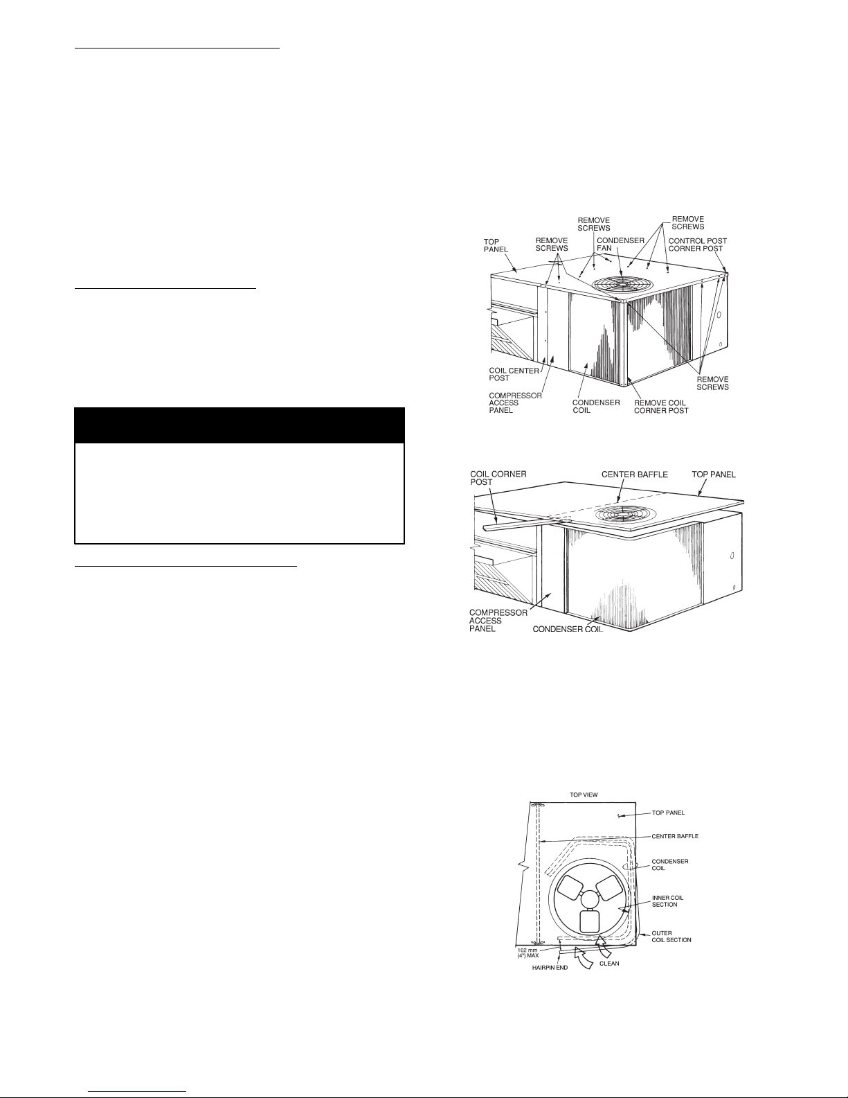
Clean coil as follows:
1. Turn off unit power and tag the disconnect.
2. Remove the top panel screws on the condenser end of
the unit.
3. Remove the condenser coil corner post. See Fig. 12.
4. Lift and hold the top cover open.
5. Hold the top pan open by placing the coil corner post
between the top panel and center post. See Fig. 13.
C08205
Fig. 12 − Cleaning Condenser Coil
Routine Cleaning of Coil Surfaces
Periodic cleaning with Totaline environmentally sound
coil cleaner is essential to extend the life of coils. This
cleaner is available from Carrier Replacement
Components Division as p/n: P902- 0301 for one-gallon
(3.8L) container, and P902- 0305 for a 5-gallon (18.9L)
container. It is recommended that all coils, including
standard aluminum, pre−coated, copper/copper or
E−coated coils be cleaned with the Totaline
environmentally sound coil cleaner as described below.
Coil cleaning should be part of the unit’s regularly
scheduled maintenance procedures to ensure long life of
the coil. Failure to clean the coils may result in reduced
durability in the environment.
Avoid use of:
coil brighteners
acid cleaning prior to painting
high pressure washers
poor quality water for cleaning
Totaline environmentally sound coil cleaner is a nonflammable, hypo allergenic, non bacterial, USDA accepted biodegradable agent that will not harm the coil or surrounding components such as electrical wiring, painted
metal surfaces, or insulation. Use of non−recommended
coil cleaners is strongly discouraged since coil and unit
durability could be affected.
C08206
Fig. 13 − Propping Up Top Panel
6. Remove the screws securing the coil to the compressor plate and compressor access panel.
7. Remove the fasteners holding the coil sections together at the return end of the condenser coil. Carefully
separate the outer coil section 3 to 4 in. from the inner coil section. See Fig. 14.
C08207
Fig. 14 − Separating Coil Sections
9

8. Clean the outer surfaces with a stiff brush in the normal manner. Use a water hose or other suitable equipment to flush down between the 2 coil sections to remove dirt and debris.
9. Secure the inner and outer coil rows together with a
field−supplied fastener.
10. Reposition the outer coil section and remove the coil
corner post from between the top panel and center
post. Reinstall the coil corner post and access panel.
11. Replace all screws.
EVAPORATOR COILS
The evaporator coil uses the traditional round-tube,
plate-fin (RTPF) technology. Tube and fin construction
consists of various optional materials and coatings (see
APPENDIX I. MODEL NUMBER NOMENCLATURE).
Coils are multiple-row. On two-compressor units, the
evaporator coil is a face split design, meaning the two
refrigerant circuits are independent in the coil. The bottom
portion of the coil will always be circuit A, with the top of
the coil being circuit B.
Coil Maintenance and Cleaning Recommendation
Routine cleaning of coil surfaces is essential to maintain
proper operation of the unit. Elimination of contamination
and removal of harmful residues will greatly increase the
life of the coil and extend the life of the unit. The
following maintenance and cleaning procedures are
recommended as part of the routine maintenance activities
to extend the life of the coil.
Removing Surface Loaded Fibers
Surface loaded fibers or dirt should be removed with a
vacuum cleaner. If a vacuum cleaner is not available, a
soft non- metallic bristle brush can be used. In either case,
the tool should be applied in the direction of the fins. Coil
surfaces can be easily damaged. Applying the tool across
the fin edges can cause the edges to be easily bent over,
damaging the coating of a protected coil.
NOTE: Use of a water stream, such as a garden hose,
against a surface-loaded coil will drive the fibers and dirt
into the coil. This will make cleaning efforts more
difficult. Surface-loaded fibers must be completely
removed prior to using a low-velocity clean water rinse. A
vacuum cleaner or a soft- bristled brush should be used to
remove surface-loaded fibers and dirt.
and p/n: P902- 0305 for a 5-gallon (18.9L) container). It is
recommended that all round tube coils be cleaned as
described below. Coil cleaning should be part of the unit’s
regularly scheduled maintenance procedures to ensure a
long life for the coil. Failure to clean the coils can result
in reduced durability in the environment. When cleaning
the coils, avoid use of the following:
coil brighteners
acid cleaning prior to painting
high pressure washers
poor quality water for cleaning
Totaline environmentally sound coil cleaner is a nonflammable, hypo allergenic, non bacterial, USDA accepted biodegradable agent that will not harm the coil or surrounding components such as electrical wiring, painted
metal surfaces, or insulation. Use of non−recommended
coil cleaners is strongly discouraged since coil and unit
durability could be affected.
TotalineR Environmentally Sound Coil Cleaner
Application Equipment
2−1/2 gallon garden sprayer
Water rinse with low velocity spray nozzle
!
WARNING
PERSONAL INJURY HAZARD
Failure to follow this WARNING can result in severe
personal injury and reduced unit performance.
High−velocity water from a pressure washer, garden
hose, or compressed air should never be used to clean
a coil. The force of the water or air jet will bend the
fin edges and increase airside pressure drop.
High−velocity water from a pressure washer can
cause severe injury upon contact with exposed body
tissue. Always direct the water stream away from the
body.
Totaline Environmentally Sound Coil Cleaner
Application Instructions
1. Proper protection such as safety glasses, gloves and
protective clothing are recommended during mixing
and application.
Periodic Clean Water Rinse
A periodic clean-water rinse is very beneficial for coils
that are used in coastal or industrial environments.
However, it is very important that the water rinse is made
with a very low-velocity water stream to avoid damage to
the fin edges. Monthly cleaning, as described below, is
recommended.
Routine Cleaning of Evaporator Coil Surfaces
Monthly cleaning with Totaline environmentally sound
coil cleaner is essential to extend the life of the coils. This
cleaner is available from Carrier Replacement Parts
Division (p/n: P902- 0301 for one-gallon (3.8L) container,
CAUTION
EQUIPMENT HAZARD
Failure to follow this CAUTION can result in
corrosion and damage to the unit.
Harsh chemicals, household bleach or acid or basic
cleaners should not be used to clean outdoor or indoor
coils of any kind. These cleaners can be very difficult
to rinse out of the coil and can accelerate corrosion at
the fin/tube interface where dissimilar materials are in
contact. If there is dirt below the surface of the coil,
use the Totaline environmentally sound coil cleaner.
10
2. Remove all surface loaded fibers and dirt with a vacuum cleaner as described above.
3. Thoroughly wet finned surfaces with clean water and
a low velocity garden hose, being careful not to bend
fins.
4. Mix Totaline environmentally sound coil cleaner in
a 2−1/2 gallon (9.6 L) garden sprayer according to the
instructions included with the cleaner. The optimum
solution temperature is 100F (38C).
NOTE: Do NOT USE water in excess of 130F (54C),
as the enzymatic activity will be destroyed.
5. Thoroughly apply Totaline environmentally sound
coil cleaner solution to all coil surfaces, including
finned area, tube sheets and coil headers.
6. Hold the garden sprayer nozzle close to finned areas
and apply cleaner with a vertical, up−and−down motion.
7. Avoid spraying in a horizontal pattern to minimize
potential for fin damage.
8. Make sure the cleaner thoroughly penetrates deep into
the finned areas.
9. Interior and exterior finned areas must be thoroughly
cleaned.
10. Finned surfaces should remain wet with cleaning solution for 10 minutes.
11. Make sure surfaces are not allowed to dry before rinsing. Reapply cleaner as needed to ensure 10−minute
saturation is achieved.
12. Thoroughly rinse all surfaces with low−velocity clean
water using a downward rinsing motion of the spray
nozzle. Protect fins from damage from the spray nozzle.
Evaporator Coil Metering Devices
The metering devices are multiple fixed−bore devices
(Acutrol) swedged into the horizontal outlet tubes from
the liquid header, located at the entrance to each
evaporator coil circuit path. These are non−adjustable.
Service requires replacing the entire liquid header
assembly.
To check for possible blockage of one or more of these
metering devices, disconnect the supply fan contactor
(IFC) coil, then start the compressor and observe the
frosting pattern on the face of the evaporator coil. A frost
pattern should develop uniformly across the face of the
coil starting at each horizontal header tube. Failure to
develop frost at an outlet tube can indicate a plugged or a
missing orifice.
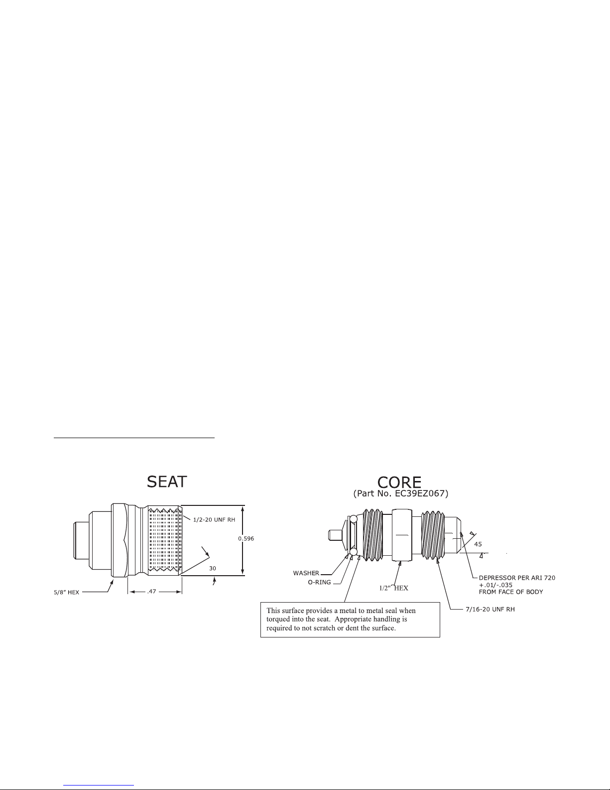
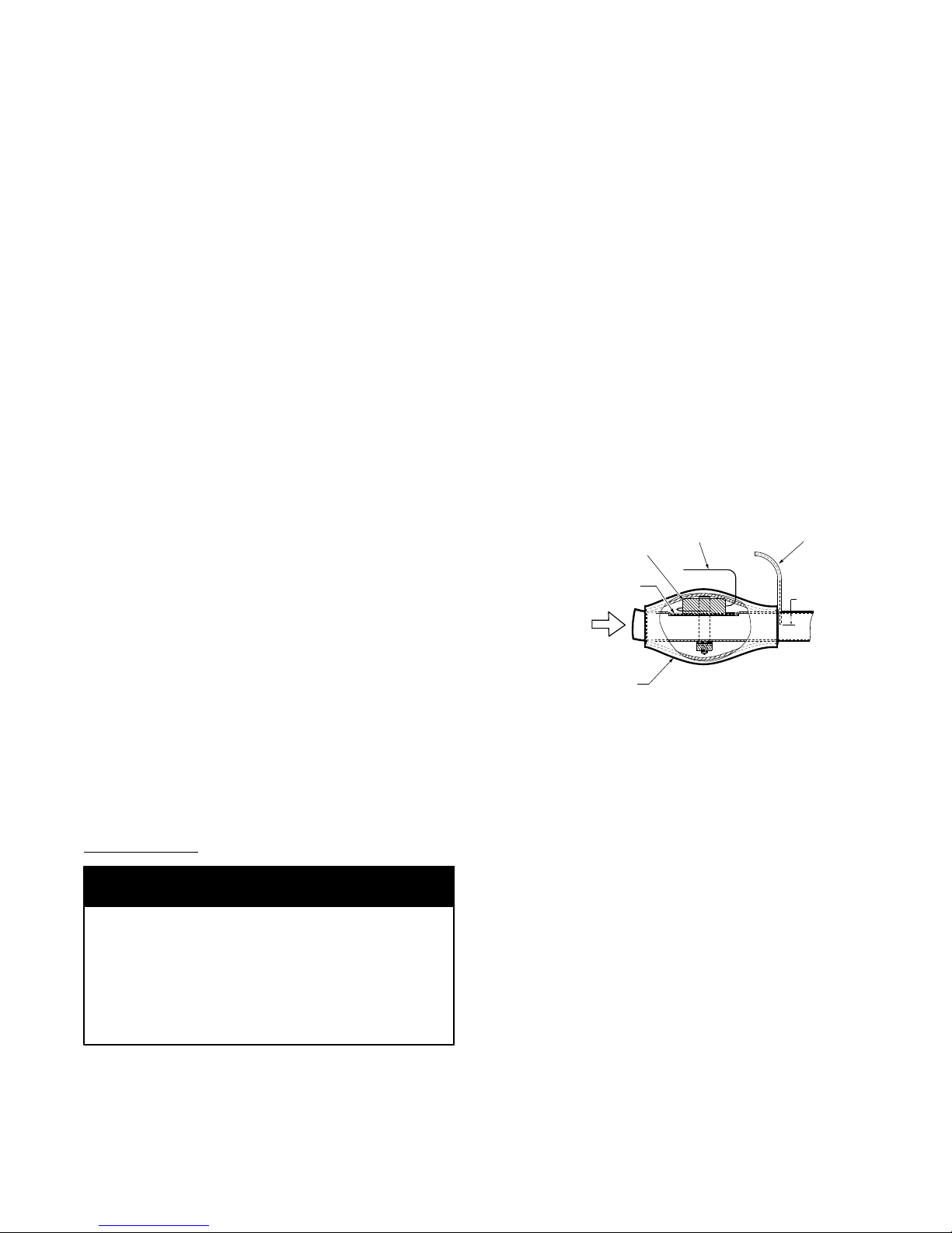
Refrigerant System Pressure Access Ports
There are two access ports in the system − on the suction
tube near the compressor and on the discharge tube near
the compressor. These are brass fittings with black plastic
caps. The hose connection fittings are standard 1/4 SAE
male flare couplings.
The brass fittings are two−piece High Flow valves, with a
receptacle base brazed to the tubing and an integral
spring−closed check valve core screwed into the base (See
Fig. 15). This schrader valve is permanently assembled
into this core body and cannot be serviced separately;
replace the entire core body if necessary. Service tools are
available from RCD (p/n P920−0010) that allow the
replacement of the schrader valve core without having to
recover the entire system refrigerant charge. Apply
compressor refrigerant oil to the schrader valve core’s
bottom o−ring. Install the fitting body with 96 ± 10 in−lbs
(10.85 ± 1.13 Nm) of torque; do not overtighten.
NOTE: The High−Flow valve has a black plastic cap
with a rubber o−ring located inside the cap. This rubber
o−ring must be in place in the cap to prevent refrigerant
leaks.
EXAMPLE:
Model 50TC*D28
Circuit A (from Fig. 15)
Outdoor Temperature 85F (29C)..................
Suction Pressure 125 psig (860 kPa).................
o
o
C08453
Fig. 15 − CoreMax Access Port Assembly
Suction Temperature should be 63F (17C)..........
Circuit B (from Fig. 15)
Outdoor Temperature 85F (29C)..................
Suction Pressure 120 psig (830 kPa).................
Suction Temperature should be 58F (14C)..........
11

HIMIDI−MIZERR ADAPTIVE
DEHUMIDIFICATION SYSTEM
Units with the factory−equipped Humidi−MiZer option
are capable of providing multiple modes of improved
dehumidification as a variation of the normal cooling
cycle. See Fig 16. The design of the Humidi−MiZer
system allows for two humidity control modes of
operation of the rooftop unit, utilizing a common
subcooling/reheat dehumidification coil located
downstream of the standard evaporator coil. This allows
the rooftop unit to operate in both a dehumidification
(Subcooling) mode and a hot gas (Reheat) mode for
maximum system flexibility. The Humidi−MiZer
package is factory−installed and will operate whenever
there is a dehumidification requirement present.
The Humidi−MiZer system is initiated based on an
input from a discrete input from a mechanical space or
return air humidistat.
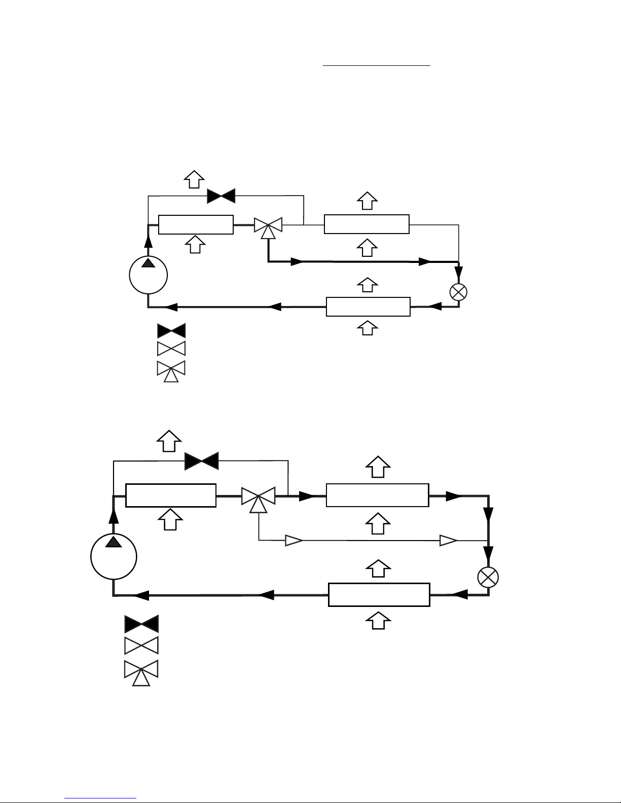
Humidi−MiZerR Modes
Normal Cooling for Units A17 − A30
During the Normal Cooling mode, the liquid refrigerant
flows from the outdoor condenser through the normally
open (NO) Cooling System Valve (CSV) to the expansion
device. Both the Reheat1 (RH1.x) and Reheat2 (RH2)
valves are closed during the normal cooling mode.
During the Normal Cooling mode, the refrigerant flows
from the outdoor compressor through the condenser coil.
The Reheat2 (RH2.x) is closed, preventing the refrigerant
from bypassing the condenser coil. The refrigerant then
flows through the open Reheat2 (RH1.x) 3−way valve to
the TXV Metering Device, bypassing the Humidi−
MiZer coil, and finally passing through the evaporator
coil before returning to the outdoor compressor. See Fig
16.
Reheat1 (Subcooling Mode) for Units A17 − A30
Th Reheat1 or Subcooling mode will be engaged to
satisfy part−load−type conditions when there is a space
call for cooling and dehumidification. Although the
temperature could have dropped and decreased the
sensible load in the space, the outdoor and/or space
humidity levels could have risen. A typical scenario could
be when the outside air is 85F (29C) with 70% to 80%
relative humidity (RH). Desired Sensible Heat Ratio
(SHR) for equipment in this scenario is typically from 0.4
to 0.7. The Humidi−MiZer unit will initiate the
Dehumidification mode when both the space temperature
and humidity are above the temperature and humidity
setpoints while attempting to meet both setpoint
requirements.
Once the humidity requirement is met, the unit can
continue to operate in normal cooling mode to meet any
remaining sensible capacity load. Alternatively, if the
sensible load is met and humidity levels remain high the
unit can switch to Hot Gas Reheat mode or Reheat2 mode
to provide neutral, dehumidified air.
During the Reheat1 or Subcooling mode, the liquid
refrigerant flows from the outdoor compressor through the
condenser coil to the Reheat1 (RH1.x) 3−way valve and
on to the Humid−Mizer coil. The Reheat2 (RH2.x)
valve is closed. The liquid refrigerant then passes through
the Humid−Mizer coil and then a metering device or
Thermostatic Expansion Valve (TXV). From the TXV, the
liquid refrigerant passes through the evaporator coil and
back to the outdoor comprssor. See Fig 17.
Reheat2 (Hot Gas Reheat Mode) for A17 − A30
This Reheat2 or Hot Gas Reheat mode is used when dehumidification is required without a need for cooling, such
as when the outside air is at a neutral temperature, but
high humidity exists. This situation requires the equipment to operate at a low SHR of 0.0 to 0.2. With no cooling requirement calling for dehumidification, the Humidi−
MiZer adaptive dehumidification system will energize
both compressors, opening the two hot gas bypass valves,
allowing refrigerant flow to the Humidi−MiZer coil to
reheat the unit’s supply air to a neutral temperature.
The hot bypassed refrigerant liquid (gas or two−phase
mixture) exits the outdoor compressor and passes through
the open Reheat1 (RH1.x) at the same time it passes
through the condenser coil to the open Reheat2 (Rh2.x) to
the Humidi−MiZer coil. After the refrigerant passes
through the Humidi−MiZer coil, it enters a TXV
metering device, decreasing the air pressure, and on to the
evaporator coil. The refrigerant is subcooled in this coil to
a temperature approaching the evaporator leaving air
temperature. The liquid refrigerant then returns to the
outdoor compressor. See Fig. 18.
The refrigerant enters the TXV and evaporator coil at a
temperature lower than the temperature in the standard
cooling operation. This lower temperature increases the
latent capacity of the evaporator. The refrigerant passes
through the evaporator turning it into a superheated vapor.
The air passing over the evaporator coil becomes colder
than it would during normal operation. As this same air
passes over the Humidi−MiZer Reheat Coil, it will be
warmed to the neutral supply air temperature.
Humidi−MiZerR System Components
The Humidi−MiZer System uses the standard unit
compressor(s), evaporator coil and Round Tube−Plate Fin
(RTPF) condenser coil. Additional refrigeration system
hardware includes a subcooler/reheat coil and control
solenoid valves. On some models, the evaporator coil
includes a TXV as a standard feature. Units with
Humidi−MiZer FIOP also include a factory−installed
head pressure control system (Motormaster I) to provide
proper liquid pressure during reheat modes. Unique
system controls include a reheat relay mode, and
evaporator coil freezestat, and secondary low pressure
switch.
Operating Sequences
The Humidi−−MiZer system provides three sub−modes
of operation: Normal Cooling, Reheat1 and Reheat2.
12
The Reheat1 and Reheat2 modes are available when the
unit is not in a heating mode and when the Low Ambient
Lockout Switch is closed.
When there is both cooling demand (thermostat Y1
demand) and dehumidification demand, circuit 1 will
operate in Subcooling (Reheat1) mode. See Fig. 17
Schematic for system refrigerant flow.
When there is only a single cooling demand, one or both
circuits will operate in Hot Gas (Reheat2) mode. The DSV
RH2.x
VALV E
RH1.x
VALV E
N/A
CONDENSER COIL
OUTDOOR AIR
solenoid valve is open ahd eht CSV solenoid is closed.
See Fig. 18 schematic for system refrigerant flow.
Subcooler/Reheat Coil
The Subcooler/Reheat Coil is mounted across the leaving
face of the unit’s evaporator coil. The coil is a one−row
design with two separate circuits.
HUMIDI-MIZER COIL
COMPRESSOR
= CLOSED VALVE
= OPEN VALVE
= 3-WAY VALVE
Fig. 16 − Normal Cooling Mode – Humidi−MiZerR System
RH2.x
VALV E
CONDENSER COIL
OUTDOOR AIR
COMPRESSOR
RH1.x
VALV E
EVAPORATOR COIL
INDOOR AIR
HUMIDI-MIZER COIL
EVAPORATOR COIL
TXV
VALV E
C07122A
TXV
VALV E
= CLOSED VALVE
= OPEN VALVE
= 3-WAY VALVE
Fig. 17 − Subcooling Mode (Reheat 1) – Humidi−MiZerR System
INDOOR AIR
C07123A
13
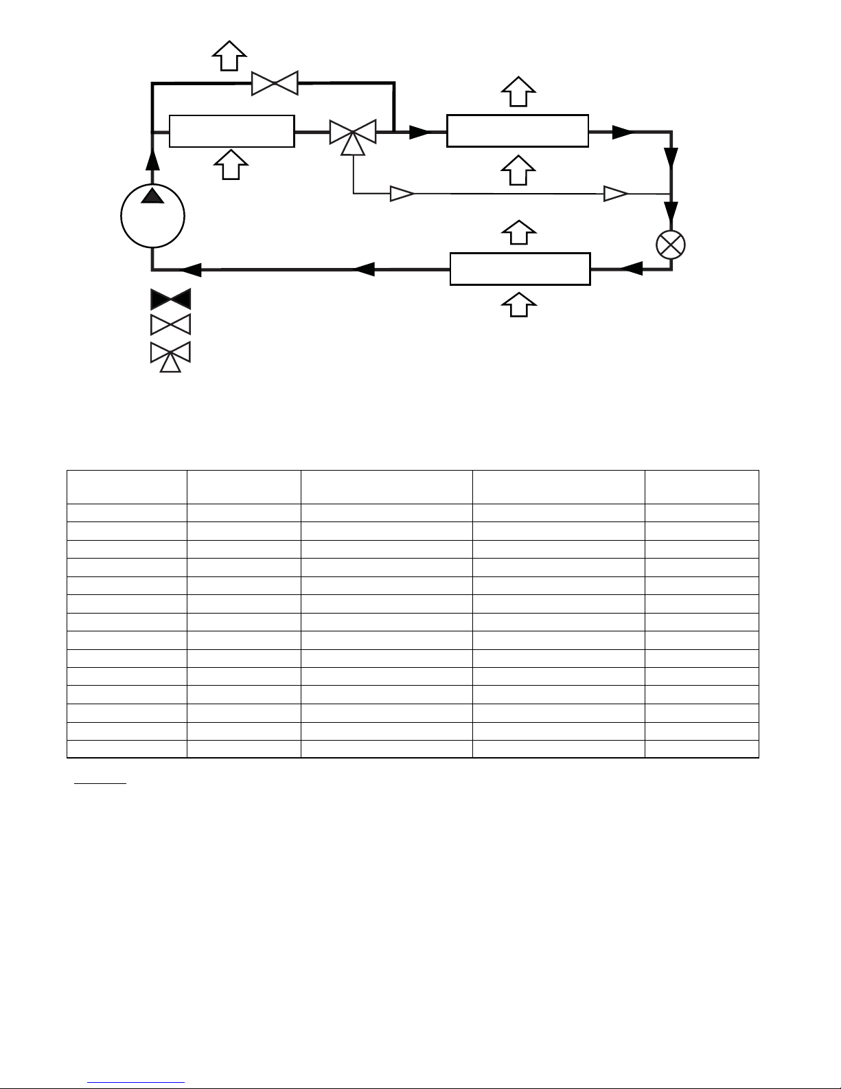
RH2.x
VALV E
CONDENSER COIL
OUTDOOR AIR
RH1.x
VALV E
HUMIDI-MIZER COIL
COMPRESSOR
EVAPORATOR COIL
= CLOSED VALVE
= OPEN VALVE
= 3-WAY VALVE
INDOOR AIR
Fig. 18 − Hot Gas Reheat Mode (Reheat 2) – Humidi−MiZerR System
Table 2 – Humidi−MiZerR Reheat Control Board I/O
Point Name Type
Connection
Pin Number
Unit
Connection
Humidistat/LTLO DI, 24VAC J1A - 1 (1) LT LO
Thermostat W1 DI, 24VAC J1A - 2 (2) CTB - REHEAT - 4
Econ Y1 DI, 24VAC J1A - 6 (6) CTB - REHEAT - 5
Thermostat G DI, 24VAC J1B - 1 (7) CTB - REHEAT - 1
24V Power (J1) 24VAC J1B - 3 (9) CTB - R
24V Power (J2) 24 VAC J2 - 1 CTB - R
Econ Y2 DI, 24VAC J1B - 5 (11) CTB - REHEAT - 7 2 - circ only
COMP1 DO, 24VAC J1A - 5 (5) CTB - HEAT - 6
IFM DO, 24VAC J1B - 4 (8) CTB - REHEAT - 2
COMP2 DO, 24VAC J1B - 4 (10) CTB - REHEAT - 8
LSV DO, 24VAC J2 - 2 FTP (BLK)
DSV1 DO, 24VAC J2 - 3 DSV
NOT LSV DO, 24VAC J2 - 4 2 - circ only
DSV2 DO, 24VAC J2 - 5 2 - circ only
TXV
VALV E
C07124A
Note
LEGEND
COMP — Compressor
CTB — Control Terminal Board
DI — Discrete Input (switch)
DO — Discrete Output (switch)
DSV — Discharge (gas) Solenoid Valve
ECON — Economizer
FPT — Freeze Protection Thermostat
IFM — Indoor (supply) Fan Motor
LSV — Liquid Solenoid Valve
LTLO — Low Temperature Lockout
REHEAT — Connection Strip REHEAT (on CTB)
14

Table 3 – Inputs/Modes/Outputs Summary
HUM
Y1 Y2 W1 G
OFF OFF OFF ON OFF Normal Fan OFF OFF ON=G OFF OFF ON=R OFF OFF
ON OFF OFF On OFF Normal Cool1 ON=Y1OFF ON=G OFF OFF ON=R OFF OFF
ON ON OFF ON OFF Normal Cool2 0N=Y2 ON ON=G OFF OFF ON=R OFF OFF
OFF OFF ON X OFF Normal Heat 1 OFF OFF ON=G OFF OFF ON=R OFF OFF
OFF OFF OFF ON ON Reheat Dehumidify ON ON ON=G ON ON OFF ON=R ON=R
ON OFF OFF ON ON Subcool
ON ON OFF ON ON Subcool
OFF OFF ON X ON Heat Over-
OFF OFF ON
+
W2
/ LT
LO
X ON Heat Over-
MODE
Cir1/ Reheat
Cir2
Cir1 and
Cir2
ride
ride
Cool1 and Cool2 /
Subcool-Dehumidify
Cool1 and Cool2 /
Subcool-Dehumidify
Heat 1 OFF OFF ON=G OFF OFF ON=R OFF OFF
Heat 1 and 2 OFF OFF ON=G OFF OFF ON=R OFF OFF
COMP1COMP
2
ON ON ON=G ON ON OFF OFF ON=R
ON ON ON=G ON ON OFF OFF OFF
IFM
LSV
1
LSV2
LSV
NOT
DSV1 DSV2
15

Table 4 – Humidi−MiZerR Troubleshooting
PROBLEM CAUSE REMEDY
General cooling mode problem See Cooling Service Troubleshooting (Table 4).
Subcooling Reheat Mode Will
Not Activate
Hot Gas Reheat Mode Will Not
Activate
No Dehumidification Demand
CRC Relay Operation
RLV, CLV or LDV Valve Operation
RDV Valve Operation
(NOTE: Normally Closed When
De-energized)
Low Latent Capacity in Subcool
ing or Hot Gas Reheat Modes
Low Sensible Capacity in Normal
Cool or Subcooling Reheat
Modes
Low Suction Pressure and High
Superheat During Normal Cool
Mode
Low Suction Pressure and High
Discharge Pressure
RDV Valve Cycling On/Off Hot Gas Reheat mode low suction pressure limit
Circuit B Will Not Operate With
Circuit A Off
LEGEND
CRC — Cooling/Reheat Control
CLV — Cooling Liquid Valve
RLV — Reheat Liquid Valve
RH — Relative Humidity
RDV — Reheat Discharge Valve
No dehumidification demand See No Dehumidification Demand, below.
CRC relay operation See CRC Relay Operation, below.
Circuit RLV, CLV or LDV valve problem See CLV, RLV or LDV Valve Operation, below.
General cooling mode problem See Cooling Service Troubleshooting (Table 4).
No dehumidification demand See No Dehumidification Demand, below.
CRC relay operation See CRC Relay Operation, below.
Circuit RLV, CLV or LDV valve problem See CLV, RLV or LDV Valve Operation, below.
Circuit RDV valve is not open See RDV Valve Operation, below.
Outdoor temperature too low
Relative humidity setpoint too low — Humidistat Check/reduce setting on accessory humidistat.
Relative humidity setpoint too low — RH sensor
Software configuration error for accessory
humidistat
Software configuration error for accessory
humidity sensor
No humidity signal Check wiring. Check humidistat or humidity sensor.
No 24V signal to input terminals
No power to output terminals Check wiring.
Relay outputs do not change state Replace faulty relay.
No 24V signal to input terminals
Solenoid coil burnout
Stuck valve Replace valve. Replace filter drier.
No 24V signal to input terminals
Solenoid coil burnout
Stuck valve Replace valve. Replace filter drier.
CLV valve open or leaking See CLV Valve Operation, above.
RDV valve open or leaking See RDV Valve Operation, above.
General cooling mode problem See Cooling Service Troubleshooting (Table 4).
RDV valve open or leaking See RDV Valve Operation, above.
General cooling mode problem See Cooling Service Troubleshooting (Table 4).
Both RLV and CLV valves closed See RLV and CLV Valve Operation, above.
Normal operation. Motormaster outdoor fan
control requires operation of circuit A.
Check Reheat 2 Circuit Limit Temperatures (Configuration → HMZR
→ RA.LO and RB.LO) using ComfortLink Scrolling Marquee.
Check Space RH Setpoints (Setpoints → RH.SP and RH.UN) and
occupancy using ComfortLink Scrolling Marquee.
Check Space Humidity Switch (Configuration UNIT RH.SW) using
ComfortLink Scrolling Marquee.
Check RH Sensor on OAQ Input (Configuration → UNIT → RH.S)
using ComfortLink Scrolling Marquee.
Check using Cool→Reheat1 Valve Test (Service Test → HMZR →
CRC) using ComfortLink Scrolling Marquee.
Check MBB relay output.
Check wiring.
Check transformer and circuit breaker.
Check using Cool→Reheat1 Valve Test (Service Test → HMZR →
CRC) using ComfortLink Scrolling Marquee.
Check CRC Relay Operation.
Check Wiring.
Check transformer and circuit beaker or fuses.
Check continuous over-voltage is less than 10%.
Check under-voltage is less than 15%.
Check for missing coil assembly parts.
Check for damaged valve enclosing tube.
Check using Cool→Reheat1 Valve Test (Service Test → HMZR →
RHV.A or RHV.B) using ComfortLink Scrolling Marquee.
Check MBB relay output.
Check wiring.
Check transformer and circuit breaker or fuses.
Check continuous over-voltage is less than 10%.
Check under-voltage is less than 15%.
Check for missing coil assembly parts.
Check for damaged valve enclosing tube.
Normal Operation During Mixed Circuit Subcooling and Hot Gas
Reheat ModesatLowerOutdoorTemperatures.
None
16
THERMOSTATIC EXPANSION
VALVE (TXV)
All two−stage 50TC units with Humidi−Mizer have a
factory installed nonadjustable thermostatic expansion
valve (TXV). The TXV will be a bi-flow, bleed port
expansion valve with an external equalizer. TXVs are
specifically designed to operate with Puron or R-22
refrigerant, use only factory authorized TXVs. See Fig.
20.
TXV Operation
The TXV is a metering device that is used in air
conditioning and heat pump systems to adjust to changing
load conditions by maintaining a preset superheat
temperature at the outlet of the evaporator coil.
The volume of refrigerant metered through the valve seat
is dependent upon the following:
1. Superheat temperature is sensed by the cap tube sensing bulb on suction the tube at the outlet of evaporator coil. This temperature is converted into pressure
by refrigerant in the bulb pushing downward on the
diaphragm which opens the valve using the push rods.
2. The suction pressure at the outlet of the evaporator
coil is transferred through the external equalizer tube
to the underside of the diaphragm.
3. The needle valve on the pin carrier is spring loaded,
exerting pressure on the underside of the diaphragm.
Therefore, the bulb pressure equals the evaporator
pressure (at the outlet of the coil) plus the spring pressure. If the evaporator load increases, the temperature
increases at the bulb, which increases the pressure on
the topside of the diaphragm, pushing the carrier
away from the seat, opening the valve and increasing
the flow of refrigerant. The increased refrigerant flow
causes increased leaving evaporator pressure which
is transferred through the equalizer tube to the underside of the diaphragm. This causes the pin carrier
spring pressure to close the TXV valve. The refrigerant flow is effectively stabilized to the load demand
with a negligible change in superheat.
Replacing TXV
CAUTION
PERSONAL INJURY HAZARD
Failure to follow this CAUTION can result in injury
to personnel and damage to components.
Always wear approved safety glasses, work gloves,
and other recommended Personal Protective
Equipment (PPE) when working with refrigerants.
1. Disconnect all AC power to the unit. Use approved
lockout/tagout procedures.
2. Using the gauge set approved for use with Puron (R−
410A) refrigerant, recover all refrigerant from the
system.
3. Remove the TXV support clamp.
4. Disconnect the liquid line at the TXV inlet.
5. Remove the liquid line connection at the TXV inlet.
6. Remove the equalizer tube from the suction line of
the coil. Use a tubing cutter to cut the brazed equalizer line approximately 2 inches (50 mm) above the
suction tube.
7. Remove the bulb from the vapor tube above the evaporator coil header outlet.
8. Install the new TXV; avoid damage to the tubing or
the valve when attaching the TXV to the distributor.
Protect the TXV against over−temperature conditions
by using wet rags and directing the torch flame tip
away from the TXV body. Connect the liquid line to
the TXV inlet by repeating the above process.
9. Attach the equalizer tube to the suction line. If the
replacement TXV has a flare nut on its equalizer line,
use a tubing cutter to remove the mechanical flare nut
from the equalizer. Then use a coupling to braze the
equalizer line to the stub (previous equalizer line) in
the suction line.
10. Attach the TXV bulb in the same location as the original (in the sensing bulb indent), wrap the bulb in protective insulation and secure using the supplied bulb
clamp. See Figs. 19 and 21.
EQUALIZER TUBE
FROM TXV VALVE
15.9 mm
(REF)
C10372
DIRECTION OF
REFRIGERANT FLOW
TXV SENSOR BULB
SENSOR BULB
INDENT
SENSOR BULB
INSULATION
CAPILLARY TUBE
TO TXV
Fig. 19 − TXV Sensor Valve Insulation
11. Route the equalizer tube through the suction connection opening (large hole) in the fitting panel and install the fitting panel in place.
12. Sweat the inlet of the TXV marked “IN” to the liquid
line. Avoid excessive heat which could damage the
valve.
13. Check for leaks.
14. Evacuate the system completely and then recharge.
15. Remove the lockout/tagout on the main power switch
and restore power to the unit.
16. Complete the charging procedure.
Refrigerant System Pressure Access Ports
There are two access ports in the system: on the suction
tube near the compressor, and on the discharge tube near
the compressor. These are brass fittings with black plastic
caps. The hose connection fittings are standard 1/4 SAE
male flare couplings. See Fig. 15.
The brass fittings are two-piece High Flow valves, with a
receptacle base brazed to the tubing and an integral
spring-closed check valve core screwed into the base. This
check valve is permanently assembled into this core body
17

and cannot be serviced separately; replace the entire core
body if necessary. Service tools are available from RCD
that allow the replacement of the check valve core without
having to recover the entire system refrigerant charge.
DIAPHRAGM
PUSHRODS
FEEDER TUBES
INLET
OUTLET
NEEDLE
VALVE
SPRING
DISTRIBUTOR
Apply compressor refrigerant oil to the check valve core’s
bottom o-ring. Install the fitting body with 96 ±10 in-lbs
of torque; do not over- tighten.
CAPILLARY TUBE
COIL
BULB
TXV SENSOR
BULBS
CIRCUIT 2
EXTERNAL EQUALIZER TUBE
C150325
Fig. 20 − Thermostatic Expansion Valve (TXV) Operation
CLAMP
TXV SENSOR
BULB
TXV
SENSOR
BULBS
TXV
(CIRCUIT 1)
Fig. 21 − TXV Sensor Bulb Locations
18
TXV
(CIRCUIT 2)
CIRCUIT 1
C12557

PURONR (R−410A) REFRIGERANT
This unit is designed for use with Puron (R−410A)
refrigerant. Do not use any other refrigerant in this
system.
CAUTION
UNIT DAMAGE HAZARD
Failure to follow this CAUTION can result in damage to
components.
The compressor is in a Puron (R−410A) refrigerant
system and uses a polyester (POE) oil. This oil is
extremely hygroscopic, meaning it absorbs water
readily. POE oils can absorb 15 times as much water as
other oils designed for HCFC and CFC refrigerants.
Avoid exposure of POE oil to the atmosphere. Exposure
to the atmosphere can cause contaminants that are
harmful to R−410A components to form. Keep POE oil
containers closed until ready for use.
Puron (R−410A) refrigerant is provided in pink (rose)
colored cylinders. These cylinders are available with and
without dip tubes; cylinders with dip tubes will have a
label indicating this feature. For a cylinder with a dip
tube, place the cylinder in the upright position (access
valve at the top) when removing liquid refrigerant for
charging. For a cylinder without a dip tube, invert the
cylinder, with theaccess valve located on the bottom,
when adding liquid refrigerant.
Because Puron (R−410A) refrigerant is a blend, it is
strongly recommended that refrigerant always be removed
from the cylinder as a liquid. Admit liquid refrigerant into
the system in the discharge line when breaking the
refrigerant system vacuum while the compresor is OFF.
Only add refrigerant (liquid) into the suction line while
the compressor is operating. If adding refrigerant into the
suction line, use a commercial metering/expansion device
at the gauge manifold; remove liquid from the cylinder,
pass it through the metering device at the gauge set, and
then pass it into the suction line as a vapor. Do not remove
Puron (R−410A) refrigerant from the cylinder as a
vapor.
specified amount of refrigerant as listed on the unit's
rating plate.
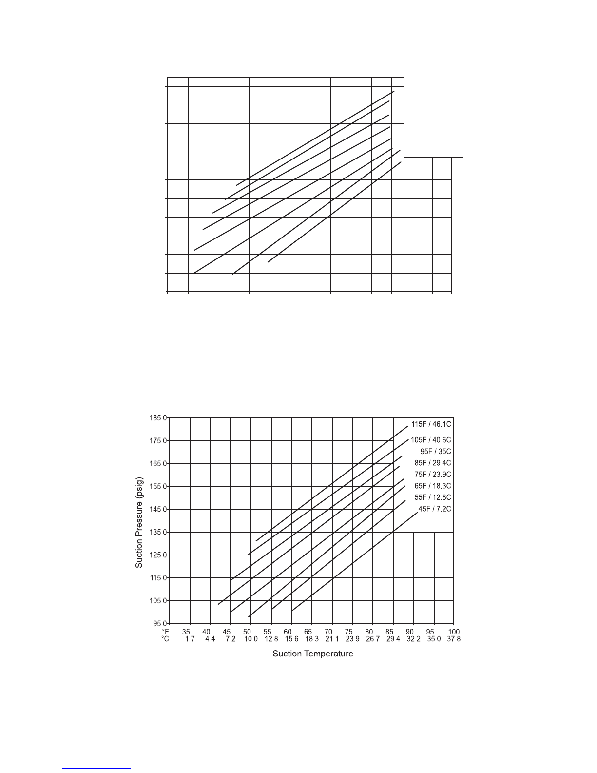
Low−Charge Cooling
Using the Cooling Charging Charts (Figs. 23 thru 30),
vary the refrigerant until the conditions of the appropriate
chart are met. Note the charging charts are different from
the type normally used. These charts are based on
charging the units to the correct superheat for the various
operating conditions. Accurate pressure gauge and
temperature sensing devices are required. Connect the
pressure gauge to the service port on the suction line.
Mount the temperature sensing device on the suction line
and insulate it so the outdoor ambient temperature does
not affect the reading. Indoor-air cfm must be within the
normal operating range of the unit.
SIZE DESIGNATION NOMINAL TON REFERENCE
17 15
20 17.5
24 20
28 25
EXAMPLE:
Model 50TC*D28
Circuit A
Outdoor Temperature 85F (29C)..................
Suction Pressure 125 psig (860 kPa).................
Suction Temperature should be 63F (17C)..........
Circuit B
Outdoor Temperature 85F (29C)..................
Suction Pressure 120 psig (830 kPa).................
Suction Temperature should be 58F (14C)..........
Using the Cooling Charging Charts
Take the outdoor ambient temperature and read the
suction pressure gauge. Refer to the chart to determine
what the suction temperature should be. If the suction
temperature is high, add refrigerant.
Refrigerant Charge
Unit panels must be in place when the unit is operating
during the charging procedure. To prepare the unit for
charge adjustment:
No Charge
Use standard evacuating techniques. Evacuate the system
down to 500 microns and let set for 10 minutes to
determine if the system has a refrigerant leak. If the
evacuation level raises to 1100 microns and stabilizes,
then the system has moisture in it and should be
dehydrated as GTAC2-5 recommends.
If the system continues to rise above 1100 microns, then
the system has a leak and should be pressurized and leak
tested using appropriate techniques as explained in
GTAC2-5. After evacuating the system, weigh in the
If the suction temperature is low, carefully recover some
of the charge. Recheck the suction pressure as the charge
is adjusted.
Select the appropriate unit charging chart from Figs. 22
thru 29.
Note the outdoor ambient temperature and read the
suction pressure gauge. Refer to the chart to determine
what the suction temperature should be. If the suction
temperature is high, add refrigerant. If the suction
temperature is low, carefully recover some of the charge.
Recheck the suction pressure as the charge is adjusted.
For 17–28 sizes, perform this procedure once for Circuit
A (using the Circuit A chart) and once for Circuit B (using
the Circuit B chart).
19

COOLING CHARGING CHARTS
COOLING CHARGING CHART
17.5 Ton - Circuit A
185.0
175.0
165.0
155.0
145.0
135.0
125.0
115.0
Suction Pressure (psig)
105.0
95.0
85.0
75.0
°
F 35 40 45 50 55 60 65 70 75 80 85 90 95 100
°
C 1.7 4.4 7.2 10.0 12.8 15.6 18.3 21.1 23.9 26.7 29.4 32.2 35.0 37.8
Suction Temperature
Fig. 22 − Cooling Charging Chart − 15 Ton (Circuit A)
115F / 46.1C
105F / 40.6C
95F / 35.0C
85F / 29.4C
75F / 23.9C
65F / 18.3C
55F / 12.8C
45F / 7.2C
50HE501045-C
C12227
COOLING CHARGING CHART
17.5 Ton - Circuit B
185.0
175.0
165.0
155.0
145.0
135.0
125.0
115.0
Suction Pressure (psig)
105.0
95.0
85.0
75.0
°
F 35 40 45 50 55 60 65 70 75 80 85 90 95 100
°
C 1.7 4.4 7.2 10.0 12.8 15.6 18.3 21.1 23.9 26.7 29.4 32.2 35.0 37.8
Suction Temperature
115F / 46.1C
105F / 40.6C
50HE501046-C
Fig. 23 − Cooling Charging Chart − 15 Ton (Circuit B)
95F / 35.0C
85F / 29.4C
75F / 23.9C
65F / 18.3C
55F / 12.8C
45F / 7.2C
12228
20
COOLING CHARGING CHARTS (cont.)
COOLING CHARGING CHART
20 Ton - Circuit A
185.0
175.0
165.0
155.0
145.0
135.0
125.0
115.0
Suction Pressure (psig)
105.0
95.0
85.0
75.0
°
F 35 40 45 50 55 60 65 70 75 80 85 90 95 100
°
C 1.7 4.4 7.2 10.0 12.8 15.6 18.3 21.1 23.9 26.7 29.4 32.2 35.0 37.8
Suction Temperature
Fig. 24 − Cooling Charging Chart − 17.5 Ton (Circuit A)
115F / 46.1C
105F / 40.6C
50HE501089-C
95F / 35.0C
85F / 29.4C
75F / 23.9C
65F / 18.3C
55F / 12.8C
45F / 7.2C
C12229
Fig. 25 − Cooling Charging Chart − 17.5 Ton (Circuit B)
C12230A
21

COOLING CHARGING CHARTS (cont.)
Fig. 26 − Cooling Charging Chart − 20 Ton (Circuit A)
C12231A
Fig. 27 − Cooling Charging Chart − 20 Ton (Circuit B)
C12232A
22

Fig. 28 − Cooling Charging Chart − 25 Ton (Circuit A)
C12233A
Fig. 29 − Cooling Charging Chart − 25 Ton (Circuit B)
C12234A
23

COMPRESSORS
Lubrication
The compressor is charged with the correct amount of oil
at the factory.
!
WARNING
FIRE, EXPLOSION HAZARD
Failure to follow this
warning could result in
death, personal personal
injury and/or property
damage.
Never use air or gases containing oxygen for leak
testing or for operating refrigerant compressors.
Pressurized mixtures of air or gases containing
oxygen can lead to an explosion.
!
WARNING
PERSONAL INJURY AND ENVIRONMENTAL
HAZARD
Failure to follow this WARNING can result in
personal injury or death.
Use a gauge set certified for use with Puron
(R−410A) refrigerant to relieve presure and recover
all refrigerant before system repair or final unit
disposal.
Wear safety glasses and gloves when handling
refrigerants.
Keep torches and other ignition sources away from
refrigerants and oils.
!
WARNING
FIRE, EXPLOSION HAZARD
Failure to follow this
warning could result in
death, personal personal
injury and/or property
damage.
Never use non−certified refrigerants in this product.
Non−certified refrigerant could contain contaminant
that could lead to unsafe operating conditions. Use
ONLY refrigerants that conform to AHRI Standard
700.
Replacing the Compressor
!
CAUTION
UNIT DAMAGE HAZARD
Failure to follow this caution may result in damage to
components.
The compressor is in a Puron refrigerant system and
uses a polyolester (POE) oil. This oil is extremely
hygroscopic, meaning it absorbs water readily. POE
oils can absorb 15 times as much water as other oils
designed for HCFC and CFC refrigerants. Avoid
exposure of the oil to the atmosphere.
NOTE: Only factory−trained service technicians should
remove and replace compressor units.
Compressor Mounting Bolts: Compressor mounting
bolts should be periodically inspected for proper tightness.
Bolts should be tightened and have the torque set at 65−75
in−lb (7.3 − 8.5 Nm).
Compressor Rotation
On 3−phase units with scroll compressors, it is important
to be certain the compressor is rotating in the proper
direction. To determine whether or not the compressor is
rotating in the proper direction:
1. Connect service gauges to suction and discharge pressure fittings.
2. Energize the compressor.
3. The suction pressure should drop and the discharge
pressure should rise, as is normal on any start−up.
NOTE: If the suction pressure does not drop and the
discharge pressure does not rise to normal levels:
4. Note that the evaporator fan is probably also rotating
in the wrong direction.
5. Turn off power to the unit. Use applicable lockout/
tagout procedures.
6. Reverse any two of the unit power leads.
7. Reapply power to the compressor.
The suction and discharge pressure levels should now
move to their normal start−up levels.
NOTE: When the compressor is rotating in the wrong
direction, the unit makes an elevated level of noise and
does not provide cooling.
Filter Drier
Replace the Filter Drier whenever the refrigerant system
is exposed to atmosphere. Only use factory specified
liquid−line filter driers with working pressures no less
than 650 psig (4482 kPa). Do not install a suction−line
filter drier in liquid line. A liquid−line filter drier designed
for use with Puron refrigerant is required on every unit.
The compressor using Puron refrigerant contains a POE
oil. This oil has a high affinity for moisture. Do not
remove the compressor’s tube plugs until ready to insert
the unit suction and discharge tube line ends.
24

Replacing the Filter Drier
Use the following steps to replace the Filter Drier.
1. Using a Puron (R410) gauge set, recover all refrig
erant from the system.
2. Use a tubing cutter to remove the filter drier from the
line.
NOTE: Do Not use a torch to remove the old filter drier.
The heat from the torch will allow contaminants into the
air and into the open refrigeration system.
3. Sweat a new replacement filter drier into the refriger
ant line.
4. Re-charge the refrigerant system.
Adjusting the Condenser−Fan
1. Shut off the unit power supply. Apply the appropriate
lockout/tagout procedures.
2. Remove the condenser−fan assembly (grille, motor,
and fan).
3. Loosen the fan hub setscrews.
4. Adjust the fan height as shown in Fig. 30.
5. Tighten the setscrews.
6. Replace the condenser−fan assembly.
C10323
Fig. 30 − Condenser Fan Adjustment
25

TROUBLESHOOTING THE COOLING SYSTEM
Refer to Table 5 for additional troubleshooting topics.
Table 5 – Cooling Service Troubleshooting
PROBLEM CAUSE REMEDY
Power failure. Call power company.
Fuse blown or circuit breaker tripped. Replace fuse or reset circuit breaker.
Compressor and Con
denser Fan Will Not Start.
Compressor Will Not
Start But Condenser Fan
Runs.
Compressor Cycles
(other than normally
satisfying thermostat).
Compressor Operates
Continuously.
Excessive Head
Pressure.
Head Pressure Too Low.
Excessive Suction
Pressure.
Suction Pressure Too
Low.
Evaporator Fan Will Not
Shut Off.
Compressor Makes
Excessive Noise.
Defective thermostat, contactor, transformer, or
control relay.
Insufficient line voltage. Determine cause and correct.
Incorrect or faulty wiring. Check wiring diagram and rewire correctly.
Thermostat setting too high. Lower thermostat setting below room temperature.
Faulty wiring or loose connections in compres
sor circuit.
Compressor motor burned out, seized, or
internal overload open.
Defective run/start capacitor, overload, start
relay.
One leg of three-phase power dead. Replace fuse or reset circuit breaker. Determine cause.
Refrigerant overcharge or undercharge.
Defective compressor. Replace defective compressor.
Insufficient line voltage. Determine cause and correct.
Blocked condenser. Determine cause and correct.
Defective run/start capacitor, overload, or start
relay.
Defective thermostat. Replace thermostat.
Faulty condenser-fan motor or capacitor. Replace. Defective fan motor or capacitor.
Restriction in refrigerant system. Locate restriction and remove.
Dirty air filter. Replace filter.
Unit undersized for load. Decrease load or replace with larger unit.
Thermostat set too low. Reset thermostat.
Low refrigerant charge. Locate leak; repair and recharge.
Leaking valves in compressor. Replace compressor.
Air in system. Recover refrigerant, evacuate system, and recharge.
Condenser coil dirty or restricted. Clean coil or remove restriction.
Dirty air filter. Replace air filter.
Dirty condenser coil. Clean condenser coil.
Refrigerant overcharged. Recover excess refrigerant.
Faulty TXV valve.
Air in system. Recover refrigerant, evacuate system, and recharge.
Condenser air restricted or air short-cycling. Determine cause and correct.
Low refrigerant charge. Check for leaks; repair and recharge.
Compressor valves leaking. Replace compressor.
Restriction in liquid tube. Remove restriction.
High head load. Check for source and eliminate.
Compressor valves leaking. Replace compressor.
Refrigerant overcharged. Recover excess refrigerant.
Dirty air filter. Replace filter.
Low refrigerant charge. Check for leaks; repair and recharge.
Metering device or low side restricted. Remove source of restriction.
Faulty TXV valve.
Insufficient evaporator airflow.
Temperature too low in conditioned area. Reset thermostat.
Outdoor ambient below 25°F. Install low-ambient kit.
Time off delay not finished. Wait for 30-second off delay.
Compressor rotating in wrong direction. Reverse the 3-phase power leads.
Replace defective component.
Check wiring and repair or replace. Tighten loose connec
tions.
Determine cause. Replace compressor.
Determine cause and replace defective component.
Recover refrigerant, evacuate system, and recharge to
values on nameplate.
Determine cause and replace.
1. Check TXV bulb mounting and secure tightly to suction
line and insulate.
2. Replace TXV valve and filter drier if stuck open or closed.
1. Check TXV bulb mounting and secure tightly to suction
line and insulate.
2. Replace TXV valve and filter drier if stuck open or closed.
Increase air quantity. Check filter and replace if
necessary. Check belt tension on blower.
26
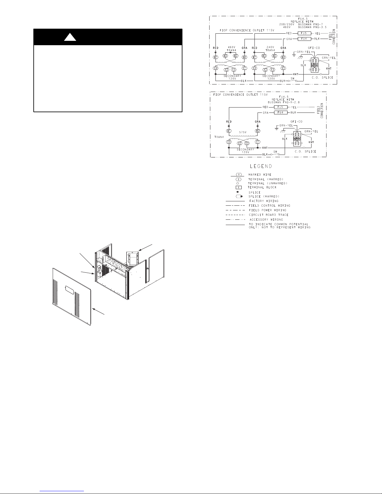
CONVENIENCE OUTLETS
!
WARNING
ELECTRICAL OPERATION HAZARD
Failure to follow this warning could result in personal
injury or death.
Units with convenience outlet circuits may use
multiple disconnects. Check convenience outlet for
power status before opening unit for service. Locate
its disconnect switch, if appropriate, and open it.
Tag−out this switch, if necessary.
Two types of convenience outlets are offered on 50HC
models: Non−powered and unit−powered. Both types
provide a 125−volt Ground−Fault Circuit−Interrupter
(GFCI) duplex receptacle rated at 15A behind a hinged
waterproof access cover, located on the end panel of the
unit. See Fig. 32.
Non−Powered Type
This type requires the field installation of a
general−purpose 125−volt 15A circuit powered from a
source elsewhere in the building. Observe national and
local codes when selecting wire size, fuse or breaker
requirements and disconnect switch size and location.
Route 125V power supply conductors into the bottom of
the utility box containing the duplex receptacle.
Pwd-CO
Convenience
Outlet
GFCI
Transformer
C10324
Fig. 32 − Powered Convenience Outlet Wiring
Pwd-CO
Fuse
Switch
Control Box
Access Panel
C08128
Fig. 31 − Convenience Outlet Location
Unit−Powered Type
A unit−mounted transformer is factory−installed to
stepdown the main power supply voltage to the unit to
115−v at the duplex receptacle. This option also includes a
manual switch with fuse, located in a utility box and
mounted on a bracket behind the convenience outlet;
access is through the unit’s control box access panel. See
Fig. 33.
UNIT
VOLTAGE
208,
230
460 480
575 600
CONNECT
AS
240
PRIMARY
CONNECTIONS
L1: RED +YEL
L2: BLU + GRA
L1: RED
Splice BLU + YEL
L2: GRA
L1: RED
L2: GRA
TRANSFORMER
TERMINALS
H1 + H3
H2 + H4
H1
H2 + H3
H4
H1
H2
Wet in Use Convenience Outlet Cover
The unit has a “wet in use” convenience outlet cover that
must be installed on the panel containing the convenience
outlet. This cover provides protection against moisture
entering the GFCI receptacle. This cover is placed in the
unit control box during shipment.
Duty Cycle
The unit-powered convenience outlet has a duty cycle
limitation. The transformer is intended to provide power
on an intermittent basis for service tools, lamps, etc. It is
not intended to provide 15-amps loading for continuous
duty loads (such as electric heaters for overnight use).
Observe a 50% limit on circuit loading above 8 amps (i.e.,
limit loads exceeding 8 amps to 30 minutes of operation
every hour).
27
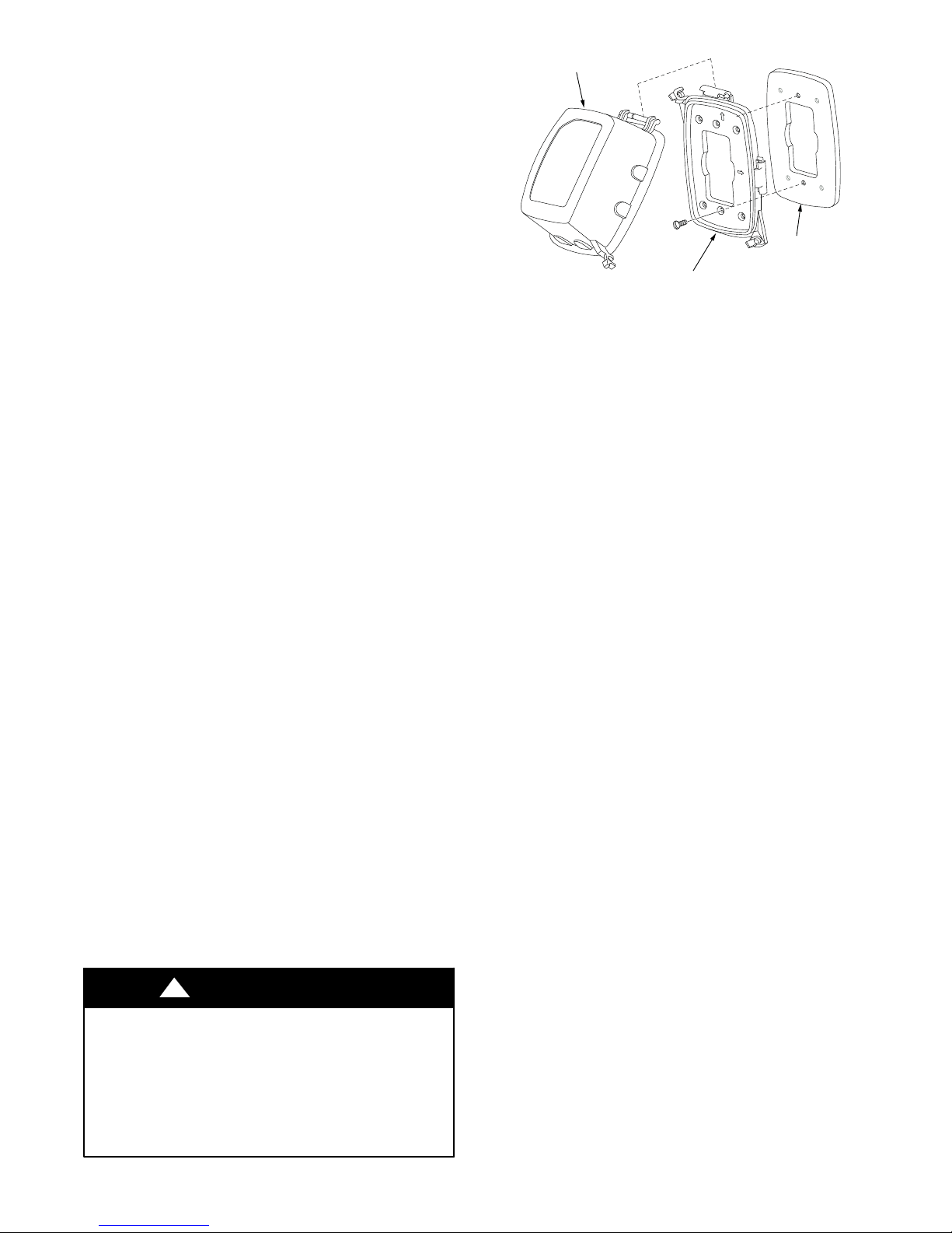
The primary leads to the convenience outlet transformer
TOP
TOP
TOP
WET L
O
C
ATION
S
WET L
OCATION S
are not factory−connected. Selection of primary power
source is a customer−option. If local codes permit, the
transformer primary leads can be connected at the
line−side terminals on a unit−mounted non−fused
disconnect or circuit breaker switch; this will provide
service power to the unit when the unit disconnect switch
or circuit breaker is open. Other connection methods will
result in the convenience outlet circuit being de−energized
when the unit disconnect or circuit breaker is open. See
Fig. 32.
GFCI Maintenance
Periodically test the GFCI receptacle by pressing the
TEST button on the face of the receptacle.
1. Press the TEST button on the face of the receptacle.
This should cause the internal circuit of the receptacle
to trip and open the receptacle.
2. Check for proper grounding and power line phasing
should the GFCI receptacle fail to trip.
3. Repair ground wire connections as needed and correct
the line phasing.
4. Press RESET button to clear the tripped condition.
Fuse On Powered Type
The factory fuse is a Bussman “Fusetron” T−15,
non−renewable screw−in (Edison base) type plug fuse.
Using Unit−Mounted Convenience Outlets
Units with unit−mounted convenience outlet circuits will
often require that two disconnects be opened to
de−energize all power to the unit. Treat all units as
electrically energized until the convenience outlet power
is also checked and de−energization is confirmed. Observe
National Electrical Code Article 210, Branch Circuits, for
use of convenience outlets. Always use a volt meter to
verify no voltage is present at the GFCI receptacles before
working on the unit.
Installing a Weatherproof Cover
A weatherproof while-in-use cover for the factory
installed convenience outlets is now required by UL
standards. This cover cannot be factory-mounted due to its
depth. The cover must be installed at the unit installation.
For shipment, the convenience outlet is covered with a
blank cover plate.
GFCI RECEPTACLE
COVER - WHILE-IN-USE
WEATHERPROOF
BASEPLATE FOR
GFCI RECEPTACLE
NOT INCLUDED
GASKET
C09022
Fig. 33 − Weatherproof Cover Installation
1. Remove the blank cover plate at the convenience outlet. Discard the blank cover.
2. Loosen the two screws at the GFCI duplex outlet until
approximately 1/2−in (13 mm) under the screw heads
is exposed.
3. Press the gasket over the screw heads. Slip the backing plate over the screw heads at the keyhole slots
and align with the gasket; tighten the two screws until
snug. Do not over−tighten.
4. Mount the weatherproof cover to the backing plate as
shown in Fig. 33.
5. Remove two slot fillers in the bottom of the cover to
allow service tool cords to exit the cover.
6. Check the cover installation to confirm full closing
and latching.
SMOKE DETECTORS
Smoke detectors are available as factory−installed options
on 50TC models. Smoke detectors may be specified for
Supply Air only or for Return Air without or with
economizer or in combination of Supply Air and Return
Air. Return Air smoke detectors are arranged for vertical
return configurations only. All components necessary for
operation are factory−provided and mounted. The unit is
factory−configured for immediate smoke detector
shutdown operation; additional wiring or modifications to
unit terminal board may be necessary to complete the unit
and smoke detector configuration to meet project
requirements.
The weatherproof cover kit is shipped in the unit’s control
box. The kit includes the hinged cover, backing plate and
gasket.
!
WARNING
ELECTRICAL OPERATION HAZARD
Failure to follow this warning could result in personal
injury or death.
Before performing service or maintenance operations
on the convenience outlets, Lockout/Tagout all
electrical power to the unit.
System
The smoke detector system consists of a four−wire
controller (HT28TZ001) and one or two sensors
(HT50TZ001). Its primary function is to shut down the
rooftop unit in order to prevent smoke from circulating
throughout the building. It is not to be used as a life
saving device.
Controller
The controller (see Fig. 34) includes a controller housing,
a printed circuit board, and a clear plastic cover. The
controller can be connected to one or two compatible duct
smoke sensors. The clear plastic cover is secured to the
housing with a single captive screw for easy access to the
28

wiring terminals. The controller has three LEDs: Power,
Trouble and Alarm. A manual test/reset button is located
on the cover face.
from a fire, causes the sensor to signal an alarm state but
dust and debris accumulated over time does not.
Duct Smoke Sensor
Controller
Conduit Nuts
(supplied by installer)
Controller Housing
and Electronics
Conduit Couplings
(supplied by installer)
Alarm
Fastener
(2X)
Cover Gasket
(ordering option)
Conduit Support Plate
Terminal Block Cover
Trouble
Power
Test/Reset
Switch
Controller Cover
C08208
Fig. 34 − Controller Assembly
Sensor
The sensor (see Fig. 35) includes a plastic housing, a
printed circuit board, a clear plastic cover, a sampling
tube inlet and an exhaust tube. The sampling tube, when
used, and exhaust tube are attached during installation.
The sampling tube varies in length depending on the size
of the rooftop unit. The clear plastic cover permits visual
inspections without having to disassemble the sensor. The
cover attaches to the sensor housing using four captive
screws and forms an airtight chamber around the sensing
electronics. Each sensor includes a harness with an RJ45
terminal for connecting to the controller. Each sensor has
four LEDs: Power, Trouble, Alarm and Dirty. A manual
test/reset button is located on the left side of the housing.
Air is introduced to the duct smoke detector sensor’s
sensing chamber through a sampling tube that extends into
the HVAC duct and is directed back into the ventilation
system through a (shorter) exhaust tube. The difference in
air pressure between the two tubes pulls the sampled air
through the sensing chamber. When a sufficient amount of
smoke is detected in the sensing chamber, the sensor
signals an alarm state and the controller automatically
takes the appropriate action to shut down fans and
blowers, change over air handling systems, notify the fire
alarm control panel, etc.
Duct Smoke Sensor
Exhaust Tube
Exhaust Gasket
Sensor Housing
Alarm
Tro ubl e
and Electronics
Power
Dirty
Cover Gasket
(ordering option)
Sensor Cover
C08209
See Detail A
Intake
Gasket
(ordering option)
Plug
Detail A
TSD-CO2
Sampling Tube
(ordered separately)
Coupling
Magnetic
Test/Reset
Switch
Fig. 35 − Smoke Detector Sensor
For installations using two sensors, the duct smoke
detector does not differentiate which sensor signals an
alarm or trouble condition.
Smoke Detector Locations
Supply Air
The Supply Air smoke detector sensor is located to the
left of the unit’s indoor (supply) fan. See Fig. 36. Access
is through the fan access panel. There is no sampling tube
used at this location. The sampling tube inlet extends
through the side plate of the fan housing (into a high
pressure area). The controller is located on a bracket to
the right of the return filter, accessed through the lift−off
filter panel.
SUPPLY AIR
SMOKE
DETECTOR
SENSOR
The sensor uses a photoelectric (light scattering principle)
process called differential sensing to prevent gradual
environmental changes from triggering false alarms. A
rapid change in environmental conditions, such as smoke
C10325
Fig. 36 − Typical Supply Air Smoke Detector Sensor
Location
29

Return Air without Economizer
FIOP Smoke Detector Wiring and Response
The sampling tube is located across the return air opening
on the unit basepan. See Fig. 37. The holes in the
sampling tube face downward, into the return air stream.
The sampling tube is attached to the control module
bushing that extends from the control box through the
partition into the return air section of the unit. The sensor
tube is shipped mounted to the Indoor Blower Housing
and must be relocated to the return air section of the unit.
Installation requires that this sensing tube be attached to
the control module bushing. See installation steps.
RETURN AIR
DETECTOR MODULE
(Shipping position
shown)*
CONTROLLER
MODULE
RETURN AIR DETECTOR
SAMPLING TUBE
*RA detector must be moved from shipping
position to operating position by installer
C07307
Fig. 37 − Typical Return Air Detector Location
Return Air with Economizer
All units: The FIOP smoke detector is configured to
automatically shut down all unit operations when a smoke
condition is detected. See Fig. 39, Smoke Detector
Wiring.
Highlight A: The JMP 3 is factory−cut, transferring unit
control to the smoke detector.
Highlight B: The smoke detector NC contact set will
open on a smoke alarm condition, de−energizing the ORN
conductor.
Highlight C: 24V power signal using the ORN lead is
removed at the Smoke Detector input on the Central
Terminal board (CTB); all unit operations cease
immediately.
PremierLinkt and RTU−−Open Controls: Unit operating
functions (fan, cooling and heating) are terminated as
described above. In addition:
Highlight D: On smoke alarm condition, the smoke
detector NO Alarm contact will close, supplying 24V
power to the GRA conductor.
Highlight E: The GRA lead at the Smoke Alarm input
on LCTB provides a 24V signal to the FIOP DDC
control.
PremierLink: This signal is conveyed to PremierLink
FIOP’s TB1 at terminal TB1−6 (BLU lead). This signal
initiates the FSD sequence by the PremierLink control.
FSD status is reported to the connected CCN network.
The sampling tube is inserted through the side plates of
the economizer housing, placing it across the return air
opening on the unit basepan. See Fig. 38. The holes in the
sampling tube face downward, into the return air stream.
The sampling tube is connected through tubing to the
return air sensor that is mounted on a bracket high on the
partition between return filter and controller location. The
Return Air Sensor is shipped in a flat−mounting location.
Installation requires that this sensor be relocated to its
operating location and the tubing to the sampling tube be
connected. See installation steps.
RTU−OPEN: The 24V signal is conveyed to the
RTU −OPEN J1−10 input terminal. This signal initiates the
FSD sequence by the RTU−OPEN control. FSD status is
reported to the connected BAS network.
Using Remote Logic: Five field−use conductors are
provided for additional annunciation functions.
Additional Application Data: Refer to Catalog number
HKRNKA−1XA for discussions on additional control
features of these smoke detectors, including multiple unit
coordination. See Fig. 39.
30

RETURN AIR SENSOR
(Operating Position Shown)
CONTROLLER
MODULE
SCREWS (2)
SAMPLE TUBE
Fig. 38 − Return Air Sampling Tube Location in Unit with Economizer
C12050
Fig. 39 − Typical Smoke Detector System Wiring
B
D
C
48TM502525 D
F
E
A
C12559
31

Sensor and Controller Tests
Sensor Alarm Test
The sensor alarm test checks a sensor’s ability to signal an
alarm state. This test requires that you use a field provided
SD−MAG test magnet.
NOTICE
OPERATIONAL TEST NOTICE
Failure to follow this NOTICE may result in an
unnecessary evacuation of the facility.
This test places the duct detector into the alarm state.
Unless part of the test, disconnect all auxiliary
equipment from the controller before performing the
test. If the duct detector is connected to a fire alarm
system, notify the proper authorities before
performing the test.
Sensor Alarm Test Procedure
1. Hold the test magnet where indicated on the side of
the sensor housing for seven seconds.
2. Verify that the sensor’s Alarm LED turns on.
3. Reset the sensor by holding the test magnet against
the sensor housing for two seconds.
4. Verify that the sensor’s Alarm LED turns off.
Controller Alarm Test
The controller alarm test checks the controller’s ability to
initiate and indicate an alarm state.
NOTICE
OPERATIONAL TEST NOTICE
Failure to follow this NOTICE may result in an
unnecessary evacuation of the facility.
This test places the duct detector into the alarm state.
Unless part of the test, disconnect all auxiliary
equipment from the controller before performing the
test. If the duct detector is connected to a fire alarm
system, notify the proper authorities before
performing the test.
Controller Alarm Test Procedure
1. Press the controller’s test/reset switch for seven seconds.
2. Verify that the controller’s Alarm LED turns on.
3. Reset the sensor by pressing the test/reset switch for
two seconds.
4. Verify that the controller’s Alarm LED turns off.
Dirty Controller Test
The dirty controller test checks the controller’s ability to
initiate a dirty sensor test and indicate its results.
NOTICE
OPERATIONAL TEST NOTICE
Failure to follow this NOTICE may result in an
unnecessary evacuation of the facility.
Pressing the controller’s test/reset switch for longer
than seven seconds will put the duct detector into the
alarm state and activate all automatic alarm responses.
Dirty Controller Test Procedure
1. Press the controller’s test/reset switch for two seconds.
2. Verify that the controller’s Trouble LED flashes.
Dirty Sensor Test
The dirty sensor test provides an indication of the sensor’s
ability to compensate for gradual environmental changes.
A sensor that can no longer compensate for environmental
changes is considered 100% dirty and requires cleaning or
replacing. You must use a field provided SD−MAG test
magnet to initiate a sensor dirty test. The sensor’s Dirty
LED indicates the results of the dirty test as shown in
Table 6.
NOTICE
OPERATIONAL TEST NOTICE
Failure to follow this NOTICE may result in an
unnecessary evacuation of the facility.
Holding the test magnet against the sensor housing for
more than seven seconds will put the duct detector
into the alarm state and activate all automatic alarm
responses.
Table 6 – Dirty LED Test
FLASHES DESCRIPTION
1 0-25% dirty. (Typical of a newly installed detector)
2 25-50% dirty
3 51-75% dirty
4 76-99% dirty
Dirty Sensor Test Procedure
1. Hold the test magnet where indicated on the side of
the sensor housing for two seconds.
2. Verify that the sensor’s Dirty LED flashes.
NOTICE
OPERATIONAL TEST NOTICE
Failure to follow this NOTICE may result in an
unnecessary evacuation of the facility.
Changing the dirty sensor test operation will put the
detector into the alarm state and activate all automatic
alarm responses. Before changing dirty sensor test
operation, disconnect all auxiliary equipment from the
controller and notify the proper authorities if
connected to a fire alarm system.
32

Changing the Dirt Sensor Test
By default, sensor dirty test results are indicated by:
The sensor’s Dirty LED flashing.
The controller’s Trouble LED flashing.
The controller’s supervision relay contacts toggle.
The operation of a sensor’s dirty test can be changed so
that the controller’s supervision relay is not used to
indicate test results. When two detectors are connected to
a controller, sensor dirty test operation on both sensors
must be configured to operate in the same manner.
To Configure the Dirty Sensor Test Operation
1. Hold the test magnet where indicated on the side of
the sensor housing for approximately 60 seconds until
the sensor’s Alarm LED turns on and its Dirty LED
flashes twice.
2. Reset the sensor by removing the test magnet and
then holding it against the sensor housing again for
approximately 2 seconds until the sensor’s Alarm
LED turns off.
12
1
3
Supervision relay
contacts [3]
Wire must be
added by installer
TB3
1
2
14
13
19
15
2
20
Smoke Detector Controller
−
Auxiliary
equipment
+
5
18 Vdc (+)
18 Vdc (
4
1
3
−)
2
SD-TR14
Tro uble
Power
Alarm
Reset/ Test
Fig. 40 − Remote Test/Reset Station Connections
C08247
Remote Station Test
The remote station alarm test checks a test/reset station’s
ability to initiate and indicate an alarm state.
NOTICE
OPERATIONAL TEST NOTICE
Failure to follow this NOTICE may result in an
unnecessary evacuation of the facility.
Changing the dirty sensor test operation will put the
detector into the alarm state and activate all automatic
alarm responses. Before changing the dirty sensor test
operation, disconnect all auxiliary equipment from the
controller and notify proper authorities if connected to
a fire alarm system.
SD−TRK4 Remote Alarm Test Procedure
1. Turn the key switch to the RESET/TEST position for
seven seconds.
2. Verify that the test/reset station’s Alarm LED turns
on.
3. Reset the sensor by turning the key switch to the
RESET/TEST position for two seconds.
4. Verify that the test/reset station’s Alarm LED turns
off.
Remote Test/Reset Station Dirty Sensor Test
The test/reset station dirty sensor test checks the test/reset
station’s ability to initiate a sensor dirty test and indicate
the results. It must be wired to the controller as shown in
Fig. 40 and configured to operate the controller’s
supervision relay. For more information, see “Changing
the Dirty Sensor Test.”
NOTICE
OPERATIONAL TEST NOTICE
Failure to follow this NOTICE can result in an
unnecessary evacuation of the facility.
If the test/reset station’s key switch is left in the
RESET/TEST position for longer than seven seconds,
the detector will automatically go into the alarm state
and activate all automatic alarm responses.
NOTICE
OPERATIONAL TEST NOTICE
Failure to follow this NOTICE can result in an
unnecessary evacuation of the facility.
Holding the test magnet to the target area for longer
than seven seconds will put the detector into the alarm
state and activate all automatic alarm responses.
Dirty Sensor Test Using an SD−TRK4
1. Turn the key switch to the RESET/TEST position for
two seconds.
2. Verify that the test/reset station’s Trouble LED flashes.
Detector Cleaning
Cleaning the Smoke Detector
Clean the duct smoke sensor when the Dirty LED is
flashing continuously or sooner if conditions warrant.
33

NOTICE
OPERATIONAL TEST NOTICE
Failure to follow this NOTICE can result in an
unnecessary evacuation of the facility.
If the smoke detector is connected to a fire alarm
system, first notify the proper authorities that the
detector is undergoing maintenance then disable the
relevant circuit to avoid generating a false alarm.
1. Disconnect power from the duct detector then remove
the sensor’s cover. (See Fig. 41.)
Sampling
tube
Airow
Fig. 41 − Sensor Cleaning Diagram
2. Using a vacuum cleaner, clean compressed air, or a
soft bristle brush, remove loose dirt and debris from
inside the sensor housing and cover.
Use isopropyl alcohol and a lint−free cloth to remove
dirt and other contaminants from the gasket on the
sensor’s cover.
3. Squeeze the retainer clips on both sides of the optic
housing then lift the housing away from the printed
circuit board.
4. Gently remove dirt and debris from around the optic
plate and inside the optic housing.
5. Replace the optic housing and sensor cover.
6. Connect power to the duct detector then perform a
sensor alarm test.
HVAC duct
Sensor
housing
Optic
plate
Retainer
clip
Optic
housing
C07305
Alarm State
The smoke detector enters the alarm state when the
amount of smoke particulate in the sensor’s sensing
chamber exceeds the alarm threshold value. (See Table 7.)
Upon entering the alarm state:
The sensor’s Alarm LED and the controller’s Alarm
LED turn on.
The contacts on the controller’s two auxiliary relays
switch positions.
The contacts on the controller’s alarm initiation relay
close.
The controller’s remote alarm LED output is activated
(turned on).
The controller’s high impedance multiple fan shutdown
control line is pulled to ground Trouble state.
The SuperDuct duct smoke detector enters the trouble
state under the following conditions:
A sensor’s cover is removed and 20 minutes pass before
it is properly secured.
A sensor’s environmental compensation limit is reached
(100% dirty).
A wiring fault between a sensor and the controller is
detected.
An internal sensor fault is detected upon entering the
trouble state:
The contacts on the controller’s supervisory relay
switch positions. (See Fig. 42.)
If a sensor trouble, the sensor’s Trouble LED the
controller’s Trouble LED turn on.
If 100% dirty, the sensor’s Dirty LED turns on and the
controller’s Trouble LED flashes continuously.
If a wiring fault between a sensor and the controller, the
controller’s Trouble LED turns on but not the sensor’s.
Tro uble
Alarm
Power
INDICATORS
Normal State
The smoke detector operates in the normal state in the
absence of any trouble conditions and when its sensing
chamber is free of smoke. In the normal state, the Power
LED on both the sensor and the controller are on and all
other LEDs are off.
Tes t /r e s et
switch
C07298
Fig. 42 − Controller Assembly
NOTE: All troubles are latched by the duct smoke
detector. The trouble condition must be cleared and then
the duct smoke detector must be reset in order to restore it
to the normal state.
34

Table 7 – Detector Indicators
CONTROL OR INDICATOR DESCRIPTION
Magnetic test/reset switch
Alarm LED Indicates the sensor is in the alarm state.
Trouble LED Indicates the sensor is in the trouble state.
Dirty LED
Power LED Indicates the sensor is energized.
Resets the sensor when it is in the alarm or trouble state. Activates or tests the sensor when it is in
the normal state.
Indicates the amount of environmental compensation used by the sensor
(flashing continuously = 100%)
Resetting Alarm and Trouble Condition Trips:
Manual reset is required to restore smoke detector systems
to Normal operation. For installations using two sensors,
the duct smoke detector does not differentiate which
sensor signals an alarm or trouble condition. Check each
sensor for Alarm or Trouble status. Clear the condition
that has generated the trip at this sensor. Then reset the
sensor by pressing and holding the reset button (on the
side) for 2 seconds. Verify that the sensor’s Alarm and
Trouble LEDs are now off. At the controller, clear its
Alarm or Trouble state by pressing and holding the
manual reset button (on the front cover) for 2 seconds.
Verify that the controller’s Alarm and Trouble LEDs are
now off. Replace all panels.
Troubleshooting
Controller’s Trouble LED is On
1. Check the Trouble LED on each sensor connected to
the controller. If a sensor’s Trouble LED is on, determine the cause and make the necessary repairs.
2. Check the wiring between the sensor and the controller. If wiring is loose or missing, repair or replace
as required.
Controller’s Trouble LED is Flashing
1. One or both of the sensors is 100% dirty.
2. Determine which Dirty LED is flashing then clean
that sensor assembly as described in the detector
cleaning section.
Sensor’s Trouble LED is On
1. Check the sensor’s Dirty LED. If it is flashing, the
sensor is dirty and must be cleaned.
2. Check the sensor’s cover. If it is loose or missing, secure the cover to the sensor housing.
3. Replace sensor assembly.
Sensor’s Power LED is Off
1. Check the controller’s Power LED. If it is off, determine why the controller does not have power and
make the necessary repairs.
2. Check the wiring between the sensor and the controller. If wiring is loose or missing, repair or replace
as required.
Controller’s Power LED is Off
1. Make sure the circuit supplying power to the controller is operational. If not, make sure JP2 and JP3
are set correctly on the controller before applying
power.
2. Verify that power is applied to the controller’s supply
input terminals. If power is not present, replace or repair wiring as required.
Remote Test/Reset Station’s Trouble LED Does
Not flash When Performing a Dirty Test, but the
Controller’s Trouble LED Does
1. Verify that the remote test/station is wired as shown
in Fig. 40. Repair or replace loose or missing wiring.
2. Configure the sensor dirty test to activate the controller’s supervision relay. See “Changing Sensor
Dirty Test Operation.”
Sensor’s Trouble LED is On, But the Controller’s
Trouble LED is OFF
Remove JP1 on the controller.
PROTECTIVE DEVICES
Compressor Protection
Overcurrent
The compressor has internal linebreak motor protection.
Reset is automatic after compressor motor has cooled.
Overtemperature
Each compressor has an internal protector to protect it
against excessively high discharge gas temperatures. Reset
is automatic.
High Pressure Switch
The system is provided with a high pressure switch
mounted on the discharge line. The switch is
stem−mounted and brazed into the discharge tube. Trip
setting is 630 psig ± 10 psig (4344 ± 69 kPa) when hot.
Reset is automatic at 505 psig (3482 kPa).
35

Low Pressure Switch
The system is protected against a loss of charge and low
evaporator coil loading condition by a low pressure switch
located on the suction line near the compressor. The
switch is stem−mounted. Trip setting is 54 psig ± 5 psig
(372 ± 34 kPa). Reset is automatic at 117 ± 5 psig (807 ±
34 kPa).
Supply (Indoor) Fan Motor Protection
!
WARNING
PERSONAL INJURY HAZARD
Failure to follow this WARNING can result in
personal injury.
Disconnect all electrical power when servicing the fan
motor. Apply appropriate lockout/tagout procedures.
Motors with 2.9 and 3.7 bhp are equipped with an internal
overtemperature or protection device. The type of device
depends on the motor size. See Table 8.
The High Static option supply fan motor is equipped with
a pilot−circuit Thermix combination overtemperature/
overcurrent protection device. This device resets
automatically. Do not bypass this switch to correct
trouble. Determine the cause and correct it.
The Thermik device is a snap−action overtemperature
protection device that is embedded in the motor windings.
The Thermik can be identified by two blue wires
extending out of the motor control box. It is a pilot−circuit
device that is wired into the unit’s 24V control circuit.
When this switch reaches its trip setpoint, it opens the
24V control circuit and causes all unit operation to cease.
This device resets automatically when the motor windings
cool. Do not bypass this switch to correct trouble.
Determine the cause and correct it.
The External Overload Breaker is an overcurrent device
used on motors with a horsepower rating of 4.7 hp or
greater. This is a specially−calibrated circuit breaker that
is UL recognized as a motor overload controller. When
the current to the motor exceeds the circuit breaker
setpoint, the device opens all motor power leads to the
motor, shutting the motor down. Reset requires a manual
reset at the overload switch. This device (designated
IFCB) is located on the side of the supply fan housing,
behind the fan access panel. The Must Hold and Must Trip
values are listed on the side of the External Overload
Breaker.
Troubleshooting Supply Fan Motor Overload
Trips
The supply fan used in 50TC units is a forward−curved
centrifugal wheel. At a constant wheel speed, this wheel
has a characteristic that causes the fan shaft load to
DECREASE when the static pressure in the unit−duct
system increases and to INCREASE when the static
pressure in the unit−duct system decreases (and fan
airflow rate increases). Motor overload conditions
typically develop when the unit is operated with an access
panel removed, with unfinished duct work, in an
economizer−open mode, or a leak develops in the duct
system that allows a bypass back to unit return opening.
Table 8 – Overcurrent Device Type
Motor Size (bhp) Overload Device Reset
1.7 Internal Linebreak Automatic
2.4 Internal Linebreak Automatic
2.9 Thermik Automatic
3.7 Thermik Automatic
4.7 External (circuit breaker) Manual
Condenser Fan Motor Protection
The condenser fan motor is internally protected against
overtemperature.
Control Circuit, 24−V
The control circuit is protected against overcurrent
conditions by a circuit breaker mounted on the control
transformer TRAN. Reset is manual.
PREMIERLINK] CONTROL
The factory−installed PremierLink Controller includes the
supply−air temperature (SAT) sensor. The outdoor air
temperature (OAT) sensor is included in the
FIOP/accessory EconoMi$er 2 package.
Refer to Fig. 43 for PremierLink connection locations.
NOTE: Refer to PremierLink Installation, Start−Up
and Configuration Instructions. Have a copy of this
manual available at unit start−up.
36

Fig. 43 − PremierLinkt Controller
C08199
The PremierLink controller is compatible with Carrier
Comfort Network (CCN) devices. This control is
designed to allow users the access and ability to change
factory−defined settings, thus expanding the function of
the standard unit control board. CCN service access tools
include System Pilot (TM), Touch Pilot (TM) and Service
Tool. (Standard tier display tools Navigator and
Scrolling Marquee are not suitable for use with latest
PremierLink controller (Version 2.x).)
The PremierLink control is factory−mounted in the
50TC unit’s main control box to the left of the LCTB.
Factory wiring is completed through harnesses connected
to the LCTB thermostat. Field connections are made at a
16−pole terminal block (TB1) located on the bottom shelf
of the unit control box in front of the PremierLink
controller The factory−installed PremierLink control
includes the supply−air temperature (SAT) sensor. The
outdoor air temperature (OAT) sensor is included in the
FIOP/accessory EconoMi$er 2 package.
37

RTU−OPEN CONTROL SYSTEM
The RTU Open controller is an integrated component of
the Carrier rooftop unit. Its internal application
programming provides optimum performance and energy
efficiency. RTU Open enables the unit to run in 100%
stand−alone control mode, Carrier’s I−Vu Open network,
or a Third Party Building Automation System (BAS).
On−board DIP switches allow you to select your protocol
(and baud rate) of choice among the four most popular
protocols in use today: BACnet, Modbus, Johnson N2 and
LonWorks.
The RTU Open control is factory−mounted in the 50TC
unit’s main control box, to the left of the Light
Commercial Terminal Board (LCTB). See Fig. 44.
Factory wiring is completed through harnesses connected
to the LCTB. Field connections for RTU Open sensors
will be made at the Phoenix connectors on the RTU Open
board. The factory−installed RTU Open control includes
the supply−air temperature (SAT) sensor. The outdoor air
temperature (OAT) sensor is included in the
FIOP/accessory EconoMi$er2 package.
Sensory/Accessory Installation
IMPORTANT: Refer to the specific sensor or accessory
instructions for its proper installation and for rooftop unit
installation refer to base unit installation instructions and
the unit’s wiring diagrams.
!
WARNING
ELECTRICAL SHOCK HAZARD
Failure to follow this warning could result in personal
injury or death, and/or equipment damage.
Disconnect and lockout/tagout electrical power before
wiring the RTU−OPEN controller.
Additional RTU−OPEN Installation and
Troubleshooting
Additional installation, wiring and troubleshooting
information for the RTU−OPEN Controller can be found
in the following manuals: “Controls, Start−up, Operation
and Troubleshooting Instructions,” and “RTU Open
Installation and Start−up Guide.”
There are a variety of sensors and accessories available
for the RTU−OPEN. Some of these can be factory or field
installed, while others are only field installable. The
RTU −OPEN controller may also require connection to a
building network system or building zoning system. All
field control wiring that connects to the RTU−OPEN must
be routed through the raceway built into the corner post of
the unit or secured to the unit control box with electrical
conduit. The unit raceway provides the UL required
clearance between high and low−voltage wiring. Pass the
control wires through the hole provided in the corner post,
then feed the wires thorough the raceway to the
RTU −OPEN. Connect the wires to the removable Phoenix
connectors and then reconnect the connectors to the board.
See Fig. 44.
38

Fig. 44 − RTU−OPEN Control Module
C10818
39

ECONOMI$ER SYSTEMS
A
IMPORTANT: Any economizer that meets the
economizer requirements as laid out in California’s Title
24 mandatory section 120.2 (fault detection and
diagnostics) and/or prescriptive section 140.4 (life−cycle
tests, damper leakage, 5 year warranty, sensor accuracy,
etc), will have a label on the economizer. Any economizer
without this label does not meet California’s Title 24. The
five year limited parts warranty referred to in section
140.4 only applies to factory installed economizers. Please
refer to your economizer on your unit.
The 50TC units may be equipped with a factory−installed
or accessory (field−installed) EconoMi$er system. Two
types are available: with a logic control system
(EconoMi$er IV) and without a control system
(EconoMi$er2). See Fig. 45 for component locations on
each type. See Figs. 46 and 47 for EconoMi$er section
wiring diagrams. Both EconoMi$ers use direct−drive
damper actuators.
WIRING
HARNESS
CTUATOR
ECONOMI$ER2
PLUG
ECONOMIER IV
CONTROLLER
OUTSIDE AIR
TEMPERATURE SENSOR
LOW AMBIENT
SENSOR
OUTDOOR
AIR HOOD
HOOD
SHIPPING
BRACKET
C06021
BAROMETRIC
RELIEF
DAMPER
GEAR DRIVEN
DAMPER
C06022
Fig. 45 − EconoMi$er IV Component Locations
FOR OCCUPANCY CONTROL
REPLACE JUMPER WITH
FIELD-SUPPLIED TIME CLOCK
8
7
DCV— Demand Controlled Ventilation
IAQ — Indoor Air Quality
LA — Low Ambient Lockout Device
OAT — Outdoor-Air Temperature
POT— Potentiometer
RAT— Return-Air Temperature
LEGEND
Potentiometer Defaults Settings:
Power Exhaust Middle
Minimum Pos. Fully Closed
DCV Max. Middle
DCV Set Middle
Enthalpy C Setting
Fig. 46 − EconoMi$er IV Wiring
NOTES:
1. 620 ohm, 1 watt 5% resistor should be removed only when using differential
enthalpy or dry bulb.
2. If a separate field-supplied 24 v transformer is used for the IAQ sensor power
supply, it cannot have the secondary of the transformer grounded.
3. For field-installed remote minimum position POT, remove black wire jumper
between P and P1 and set control minimum position POT to the minimum
position.
40
C06028

BLACK
500 OHM
RESISTOR
VIOLET
NOTE 1
RUN
NOTE 3
50HJ540573
ACTUATOR
ASSEMBLY
DIRECT DRIVE
ACTUATOR
NOTES:
1. Switch on actuator must be in run position for economizer to operate.
2. PremierLink™ control requires that the standard 50HJ540569 outside-air sensor be replaced by either the CROASENR001A00 dry bulb sen
sor or HH57A077 enthalpy sensor.
3. 50HJ540573 actuator consists of the 50HJ540567 actuator and a harness with 500-ohm resistor.
OAT SENSOR
4-20mA SIGNAL
PINK
YELLOW
WHITE
4
TRANSFORMER
GROUND
3
5
BLUE
2
8
6
7
RED
ECONOMISER2 PLUG
10
12
24 VAC
1
11
9
4-20 mA
TO J9 ON
PremierLink
BOARD
C08310
Fig. 47 − EconoMi$er2 with 4 to 20 mA Control Wiring
Table 9 – EconoMi$er IV Input/Output Logic
INPUTS OUTPUTS
Demand Control
Ventilation (DCV)
(Free Cooling LED Off)
Below set
(DCV LED Off)
(Free Cooling LED On)
Enthalpy*
Outdoor Return
High
Low
Low
High
Y1 Y2
On On On On
On Off On Off
Off Off Off Off
On On On Off
On Off Off Off
Off Off Off Off Minimum position Closed
On On On On
On Off On Off
Off Off Off Off
On On On Off
On Off Off Off
Above set
(DCV LED On)
(Free Cooling LED Off)
High
Low
(Free Cooling LED On)
Low
High
Off Off Off Off
* For single enthalpy control, the module compares outdoor enthalpy to the ABCD setpoint.
† Power at N terminal determines Occupied/Unoccupied setting: 24 vac (Occupied), no power (Unoccupied).
** Modulation is based on the supply‐air sensor signal.
†† Modulation is based on the DCV signal.
*** Modulation is based on the greater of DCV and supply‐air sensor signals, between minimum position and either maximum
position (DCV) or fully open (supply‐air signal).
††† Modulation is based on the greater of DCV and supply‐air sensor signals, between closed and either maximum position
(DCV) or fully open (supply‐air signal).
Compressor N Terminal†
Stage1Stage
2
Occupied Unoccupied
Damper
Minimum position Closed
Modulating** (between min.
position and full‐open)
Modulating†† (between min.
position and DCV
maximum)
Modulating*** Modulating†††
Modulating** (between
closed and full‐open)
Modulating†† (between
closed and DCV
maximum)
41

Fig. 48 − EconoMi$er IV Functional View
C06053
EconoMi$er IV Standard Sensors
Table 9 provides a summary of EconoMi$er IV I/O logic.
A functional view of the EconoMi$er is shown in Fig. 48.
Typical settings, sensor ranges, and jumper positions are
also shown. An EconoMi$er IV simulator program is
available to help with EconoMi$er IV training and
troubleshooting.
Outdoor Air Temperature (OAT) Sensor
The outdoor air temperature sensor (HH57AC074) is a 10
to 20 mA device used to measure the outdoor-air
temperature. The outdoor-air temperature is used to
determine when the EconoMi$er IV can be used for free
cooling. The sensor is factory-installed on the
EconoMi$er IV in the outdoor airstream. See Fig. 49. The
operating range of temperature measurement is 40 to
100F (4 to 38C). See Fig. 67.
Supply Air Temperature (SAT) Sensor
The supply air temperature sensor is a 3 K thermistor
located at the inlet of the indoor fan. See Fig. 49. This
sensor is factory installed. The operating range of
temperature measurement is 0° to 158F (−18 to 70C).
See Table 49 for sensor temperature/resistance values.
The temperature sensor looks like an eyelet terminal with
wires running to it. The sensor is located in the “crimp
end” and is sealed from moisture.
Outdoor Air Lockout Sensor
The EconoMi$er IV is equipped with an ambient
temperature lockout switch located in the outdoor
airstream which is used to lock out the compressors below
a 42F (6C) ambient temperature. See Fig. 61.
SUPPLY
AIR TEMPERATURE
SENSOR MOUNTING
LOCATION
SUPPLY AIR
TEMPERATURE
SENSOR
(SEALED
INSIDE CRIMP
END)
C06033
Fig. 49 − Supply Air Sensor Location
EconoMi$er IV Control Modes
IMPORTANT: The optional EconoMi$er2 does not include
a controller. The EconoMi$er2 is operated by a 4 to 20
mA signal from an existing field-supplied controller. See
Fig. 62 for wiring information.
Determine the EconoMi$er IV control mode before set up
of the control. Some modes of operation may require
different sensors. The EconoMi$er IV is supplied from the
factory with a supply−air temperature sensor and an
outdoor− air temperature sensor. This allows for operation
of the EconoMi$er IV with outdoor air dry bulb
changeover control. Additional accessories can be added
to allow for different types of changeover control and
operation of the EconoMi$er IV and unit.
42
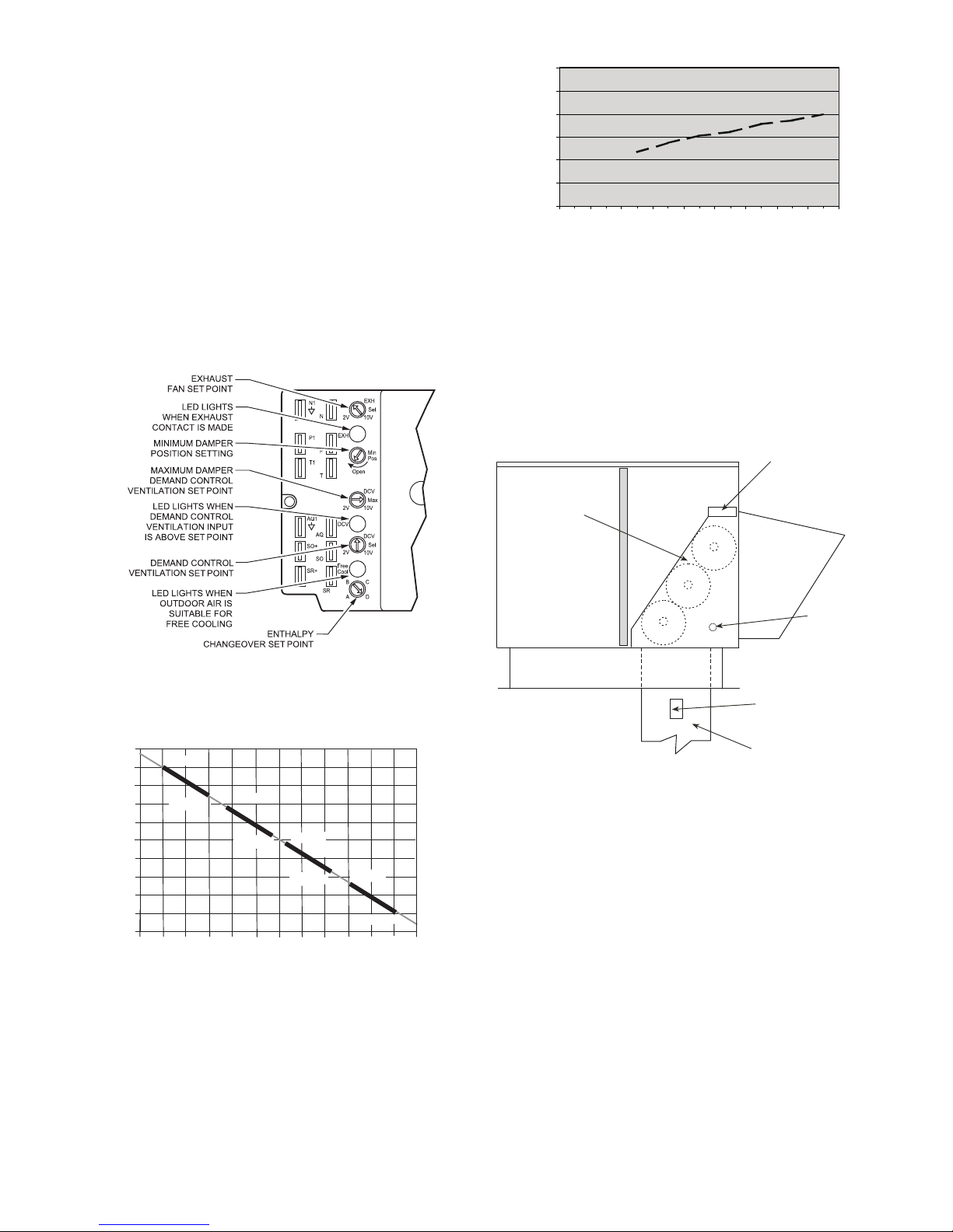
Outdoor Dry Bulb Changeover
The standard controller is shipped from the factory
configured for outdoor dry bulb changeover control. The
outdoor air and supply air temperature sensors are
included as standard. For this control mode, the outdoor
temperature is compared to an adjustable setpoint selected
on the control. If the outdoor-air temperature is above the
setpoint, the EconoMi$er IV will adjust the outside air
dampers to minimum position. If the outdoor-air
temperature is below the setpoint, the position of the
outside air dampers will be controlled to provided free
cooling using outdoor air. When in this mode, the LED
next to the free cooling setpoint potentiometer will be on.
The changeover temperature setpoint is controlled by the
free cooling setpoint potentiometer located on the control.
See Fig. 50. The scale on the potentiometer is A, B, C,
and D. See Fig. 51 for the corresponding temperature
changeover values.
30
25
20
15
10
5
0
0.13 0. 20 0.22 0.25 0.30 0.35 0 .40 0.45 0. 50
FLOW IN CUBIC FEET PER MINUTE (cfm)
STATIC PRESSURE (in. wg)
C06031
Fig. 52 − Outdoor−Air Damper Leakage
Differential Dry Bulb Control
For differential dry bulb control the standard outdoor dry
bulb sensor is used in conjunction with an additional
accessory dry bulb sensor (p/n: CRTEMPSN002A00). The
accessory sensor must be mounted in the return airstream.
See Fig. 53. Wiring is provided in the EconoMi$er IV
wiring harness.
ECONOMI$ER IV
CONTROLLER
C06034
Fig. 50 − EconoMi$er IV Controller Potentiometer
and LED Locations
19
LED ON
17
mA
14
13
12
11
18
16
15
10
9
40
LED OFF
45
D
50
60
55
DEGREES FAHRENHEIT
LED ON
LED OFF
65
C
LED ON
B
LED ON
A
LED OFF
100
90
95
85
80
C06035
70
LED OFF
75
Fig. 51 − Outside Air Temperature Changeover
Setpoints
ECONOMI$ER IV
GROMMET
RETURN AIR
SENSOR
RETURN DUCT
(FIELD-PROVIDED)
C07085
Fig. 53 − Return Air Temperature or Enthalpy Sensor
Mounting Location
In this mode of operation, the outdoor-air temperature is
compared to the return-air temperature and the lower
temperature airstream is used for cooling. When using this
mode of changeover control, turn the enthalpy setpoint
potentiometer fully clockwise to the D setting. See Fig. 50.
Outdoor Enthalpy Changeover
For enthalpy control, accessory enthalpy sensor (p/n:
HH57AC078) is required. Replace the standard outdoor
dry bulb temperature sensor with the accessory enthalpy
sensor in the same mounting location. See Fig. 70. When
the outdoor air enthalpy rises above the outdoor enthalpy
changeover setpoint, the outdoor-air damper moves to its
minimum position. The outdoor enthalpy changeover
setpoint is set with the outdoor enthalpy setpoint
potentiometer on the EconoMi$er IV controller. The
setpoints are A, B, C, and D. See Fig. 51. The
factory-installed 620-ohm jumper must be in place across
terminals SR and SR+ on the EconoMi$er IV controller.
43
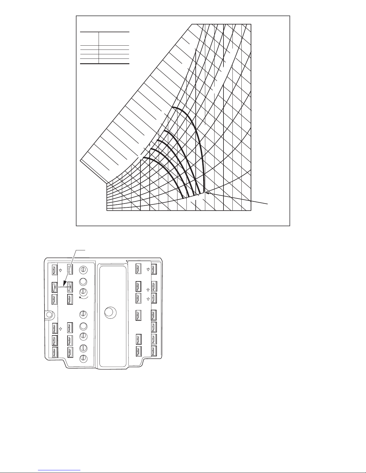
CONTROL
CURVE
4
1
2
1
A
B
C
D
1
CONTROL POINT
APPROX.
AT 50% RH
73 (23)
7 (21)
7 (19)
3 (17)
2
2
2
1
3
(2)
deg. F (deg. C)
3
4
3
32
3
2
ENTHALPY BTU PER POUND DRY AIR
2
4
2
(13)
(1 )
4
D
(7)
4
(4)
(1 )
42
4
3
7
(21)
1
(1 )
(29)9(32)9(3 )1(3 )1(41)11(43)
4
4
4
(27)
7
(24)
RELATIVE HUMIDITY (%)
9
7
4
3
2
1
35
40
(2)
4
(4)
(7)
(1 )
(13)
(1 )
(1 )
APPROXIMATE DRY BULB TEMPERATURE--degrees F (degrees C)
Fig. 54 − Enthalpy Changeover Setpoints
FACTORY JUMPER
TR1
N1
P1
T1
AQ1
SO+
SR+
EXH
2V 10V
Open
2V 10V
2V 10V
Free
Cool
B
A
C
Set
EXH
Min
Pos
DCV
Max
DCV
DCV
Set
D
N
P
T
AQ
SO
SR
TR
24
24 Vac
Va c
COM
HOT
_
+
12
5
4
3
EF1
EF
C06038
Fig. 55 − EconoMi$er IV Control
Differential Enthalpy Control
For differential enthalpy control, the EconoMi$er IV
controller uses two enthalpy sensors (HH57AC078 and
CRENTDIF004A00), one in the outside air and one in the
return air duct. The EconoMi$er IV controller compares
7
(21)
D
7
(24)
(27)
(29)9(32)9(3 )1(3 )
1
(41)11(43)
HIGH LIMIT
CURVE
the outdoor air enthalpy to the return air enthalpy to
determine EconoMi$er IV use. The controller selects the
lower enthalpy air (return or outdoor) for cooling. For
example, when the outdoor air has a lower enthalpy than
the return air, the EconoMi$er IV opens to bring in
outdoor air for free cooling.
Replace the standard outside air dry bulb temperature
sensor with the accessory enthalpy sensor in the same
mounting location. See Fig. 45. Mount the return air
enthalpy sensor in the return air duct. See Fig. 53. Wiring
is provided in the EconoMi$er IV wiring harness. See Fig.
46. The outdoor enthalpy changeover setpoint is set with
the outdoor enthalpy setpoint potentiometer on the
EconoMi$er IV controller. When using this mode of
changeover control, turn the enthalpy setpoint
potentiometer fully clockwise to the D setting.
Indoor Air Quality (IAQ) Sensor Input
The IAQ input can be used for demand control ventilation
control based on the level of CO2 measured in the space
or return air duct.
Mount the accessory IAQ sensor according to
manufacturer specifications. The IAQ sensor should be
wired to the AQ and AQ1 terminals of the controller.
Adjust the DCV potentiometers to correspond to the DCV
voltage output of the indoor air quality sensor at the
user-determined setpoint. See Fig. 56.
C06037
44

CO SENSOR MAX RANGE SETTING
2
6000
5000
4000
3000
2000
1000
RANGE CONFIGURATION (ppm)
0
2345678
DAMPER VOLTAGE FOR MAX VENTILATION RATE
800 ppm
900 ppm
1000 ppm
1100 ppm
C06039
Fig. 56 − CO2 Sensor Maximum Range Settings
If a separate field-supplied transformer is used to power
the IAQ sensor, the sensor must not be grounded or the
EconoMi$er IV control board will be damaged.
When using demand ventilation, the minimum damper
position represents the minimum ventilation position for
VOC (volatile organic compounds) ventilation
requirements. The maximum demand ventilation position
is used for fully occupied ventilation.
When demand ventilation control is not being used, the
minimum position potentiometer should be used to set the
occupied ventilation position. The maximum demand
ventilation position should be turned fully clockwise.
Exhaust Setpoint Adjustment
The exhaust setpoint will determine when the exhaust fan
runs based on damper position (if accessory power
exhaust is installed). The setpoint is modified with the
Exhaust Fan Setpoint (EXH SET) potentiometer. See Fig.
50. The setpoint represents the damper position above
which the exhaust fans will be turned on. When there is a
call for exhaust, the EconoMi$er IV controller provides a
45 ± 15 second delay before exhaust fan activation to
allow the dampers to open. This delay allows the damper
to reach the appropriate position to avoid unnecessary fan
overload.
Minimum Position Control
There is a minimum damper position potentiometer on the
EconoMi$er IV controller. See Fig. 50. The minimum
damper position maintains the minimum airflow into the
building during the occupied period.
When using demand ventilation, the minimum damper
position represents the minimum ventilation position for
Volatile Organic Compound (VOC) ventilation
requirements. The maximum demand ventilation position
is used for fully occupied ventilation.
When demand ventilation control is not being used, the
minimum position potentiometer should be used to set the
occupied ventilation position. The maximum demand
ventilation position should be turned fully clockwise.
Adjust the minimum position potentiometer to allow the
minimum amount of outdoor air, as required by local
codes, to enter the building. Make minimum position
adjustments with at least 10F temperature difference
between the outdoor and return-air temperatures.
To determine the minimum position setting, perform the
following procedure:
1. Calculate the appropriate mixed air temperature
using the following formula:
OA
(T
O x
100 100
+ (TR x
)
RA
) =T
M
TO = Outdoor-Air Temperature
OA = Percent of Outdoor Air
= Return-Air Temperature
T
R
RA = Percent of Return Air
TM = Mixed-Air Temperature
As an example, if local codes require 10% outdoor
air during occupied conditions, outdoor-air
temperature is 60F, and return-air temperature is
75F.
(60 x .10) + (75 x .90) = 73.5F
2. Disconnect the supply air sensor from terminals T
and T1.
3. Ensure that the factory-installed jumper is in place
across terminals P and P1. If remote damper
positioning is being used, make sure that the
terminals are wired according to Fig. 52 and that the
minimum position potentiometer is turned fully
clockwise.
4. Connect 24 vac across terminals TR and TR1.
5. Carefully adjust the minimum position
potentiometer until the measured mixed air
temperature matches the calculated value.
6. Reconnect the supply air sensor to terminals T and
T1.
Remote control of the EconoMi$er IV damper is desirable
when requiring additional temporary ventilation. If a
field-supplied remote potentiometer (Honeywell p/n:
S963B1128) is wired to the EconoMi$er IV controller, the
minimum position of the damper can be controlled from a
remote location.
To control the minimum damper position remotely,
remove the factory-installed jumper on the P and P1
terminals on the EconoMi$er IV controller. Wire the
field-supplied potentiometer to the P and P1 terminals on
the EconoMi$er IV controller. (See Fig. 54.)
Damper Movement
Damper movement from full open to full closed (or vice
versa) takes 21/2 minutes.
Thermostats
The EconoMi$er IV control works with conventional
thermostats that have a Y1 (cool stage 1), Y2 (cool stage
2), W1 (heat stage 1), W2 (heat stage 2), and G (fan). The
EconoMi$er IV control does not support space
temperature sensors. Connections are made at the
thermostat terminal connection board located in the main
control box.
Occupancy Control
The factory default configuration for the EconoMi$er IV
control is occupied mode. Occupied status is provided by
the black jumper from terminal TR to terminal N. When
45

unoccupied mode is desired, install a field−supplied
timeclock function in place of the jumper between TR and
N. When the timeclock contacts are closed, the
EconoMi$er IV control will be in occupied mode. When
the timeclock contacts are open (removing the 24V signal
from terminal N), the EconoMi$er IV will be in
unoccupied mode.
Demand Control Ventilation (DCV)
When using the EconoMi$er IV for demand controlled
ventilation, there are some equipment selection criteria
which should be considered. When selecting the heat
capacity and cool capacity of the equipment, the
maximum ventilation rate must be evaluated for design
conditions. The maximum damper position must be
calculated to provide the desired fresh air.
Typically the maximum ventilation rate will be about 5 to
10% more than the typical cfm required per person, using
normal outside air design criteria.
A proportional anticipatory strategy should be taken with
the following conditions: a zone with a large area, varied
occupancy, and equipment that cannot exceed the required
ventilation rate at design conditions. Exceeding the
required ventilation rate means the equipment can
condition air at a maximum ventilation rate that is greater
than the required ventilation rate for maximum
occupancy. A proportional-anticipatory strategy will cause
the fresh air supplied to increase as the room CO2 level
increases even though the CO2 setpoint has not been
reached. By the time the CO2 level reaches the setpoint,
the damper will be at maximum ventilation and should
maintain the setpoint.
In order to have the CO2 sensor control the economizer
damper in this manner, first determine the damper voltage
output for minimum or base ventilation. Base ventilation
is the ventilation required to remove contaminants during
unoccupied periods. The following equation may be used
to determine the percent of outside air entering the
building for a given damper position. For best results there
should be at least a 10 degree difference in outside and
return-air temperatures.
OA
(T
O x
100 100
+ (TR x
)
RA
) =T
M
TO = Outdoor-Air Temperature
OA = Percent of Outdoor Air
TR = Return-Air Temperature
RA = Percent of Return Air
TM = Mixed-Air Temperature
Once base ventilation has been determined, set the
minimum damper position potentiometer to the correct
position.
The same equation can be used to determine the occupied
or maximum ventilation rate to the building. For example,
an output of 3.6 volts to the actuator provides a base
ventilation rate of 5% and an output of 6.7 volts provides
the maximum ventilation rate of 20% (or base plus 15 cfm
per person). Use Fig. 56 to determine the maximum
setting of the CO2 sensor. For example, an 1100 ppm
setpoint relates to a 15 cfm per person design. Use the
1100 ppm curve on Fig. 56 to find the point when the CO
sensor output will be 6.7 volts. Line up the point on the
graph with the left side of the chart to determine that the
range configuration for the CO2 sensor should be 1800
ppm. The EconoMi$er IV controller will output the 6.7
volts from the CO2 sensor to the actuator when the CO
concentration in the space is at 1100 ppm. The DCV
setpoint may be left at 2 volts since the CO2 sensor
voltage will be ignored by the EconoMi$er IV controller
until it rises above the 3.6 volt setting of the minimum
position potentiometer.
Once the fully occupied damper position has been
determined, set the maximum damper demand control
ventilation potentiometer to this position. Do not set to the
maximum position as this can result in over-ventilation to
the space and potential high humidity levels.
CO2 Sensor Configuration
The CO2 sensor has preset standard voltage settings that
can be selected anytime after the sensor is powered up.
See Table 10.
Use setting 1 or 2 for CarrierBryant equipment. See Table
10.
1. Press Clear and Mode buttons. Hold at least 5
seconds until the sensor enters the Edit mode.
2. Press Mode twice. The STDSET Menu will appear.
Table 10 – EconoMi$er IV Sensor Usage
ECONOMI$ER IV WITH OUTDOOR AIR DRY
APPLICATION
Outdoor Air
Dry Bulb
Differential
Dry Bulb
Single Enthalpy HH57AC078
Differential
Enthalpy
CO2 for DCV
Control using a
Wall‐Mounted
CO2 Sensor
CO2 for DCV
Control using a
Duct‐Mounted
CO2 Sensor
* CRENTDIF004A00 and CRTEMPSN002A00 accessories are
used on many different base units. As such, these kits may
contain parts that will not be needed for installation.
† 33ZCSENCO2 is an accessory CO2 sensor.
** 33ZCASPCO2 is an accessory aspirator box required for duct‐
mounted applications.
†† CRCBDIOX005A00 is an accessory that contains both
33ZCSENCO2 and 33ZCASPCO2 accessories.
None. The outdoor air dry bulb sensor is
HH57AC078 and CRENTDIF004A00*
33ZCSENCO2† and
33ZCASPCO2**OR
BULB SENSOR
Accessories Required
factory installed.
CRTEMPSN002A00*
33ZCSENCO2
CRCBDIOX005A00††
3. Use the Up/Down button to select the preset
number. See Table 10.
4. Press Enter to lock in the selection.
5. Press Mode to exit and resume normal operation.
The custom settings of the CO2 sensor can be changed
anytime after the sensor is energized. Follow the steps
below to change the non-standard settings:
1. Press Clear and Mode buttons. Hold at least 5
seconds until the sensor enters the Edit mode.
2
2
46

2. Press Mode twice. The STDSET Menu will appear.
3. Use the Up/Down button to toggle to the NONSTD
menu and press Enter.
4. Use the Up/Down button to toggle through each of
the nine variables, starting with Altitude, until the
desired setting is reached.
5. Press Mode to move through the variables.
6. Press Enter to lock in the selection, then press Mode
to continue to the next variable.
Dehumidification of Fresh Air with DCV (Demand
Controlled Ventilation) Control
If normal rooftop heating and cooling operation is not
adequate for the outdoor humidity level, an energy
recovery unit and/or a dehumidification option should be
considered.
EconoMi$er IV Preparation
This procedure is used to prepare the EconoMi$er IV for
troubleshooting. No troubleshooting or testing is done by
performing the following procedure.
NOTE: This procedure requires a 9V battery, 1.2
kilo−ohm resistor, and a 5.6 kilo−ohm resistor which are
not supplied with the EconoMi$er IV.
IMPORTANT: Be sure to record the positions of all
potentiometers before starting troubleshooting.
1. Disconnect power at TR and TR1. All LEDs should
be off. Exhaust fan contacts should be open.
2. Disconnect device at P and P1.
3. Jumper P to P1.
4. Disconnect wires at T and T1. Place 5.6 kilo−ohm resistor across T and T1.
5. Jumper TR to 1.
6. Jumper TR to N.
7. If connected, remove sensor from terminals SO and +.
Connect 1.2 kilo−ohm 4074EJM checkout resistor
across terminals SO and +.
8. Put 620−ohm resistor across terminals SR and +.
9. Set minimum position, DCV setpoint, and exhaust potentiometers fully CCW (counterclockwise).
10. Set DCV maximum position potentiometer fully CW
(clockwise).
11. Set enthalpy potentiometer to D.
12. Apply power (24 vac) to terminals TR and TR1.
Differential Enthalpy
To check differential enthalpy:
1. Make sure EconoMi$er IV preparation procedure has
been performed.
2. Place 620−ohm resistor across SO and +.
3. Place 1.2 kilo−ohm resistor across SR and +. The
Free Cool LED should be lit.
4. Remove 620−ohm resistor across SO and +. The Free
Cool LED should turn off.
5. Return EconoMi$er IV settings and wiring to normal
after completing troubleshooting.
Single Enthalpy
To check single enthalpy:
1. Make sure EconoMi$er IV preparation procedure has
been performed.
2. Set the enthalpy potentiometer to A (fully CCW). The
Free Cool LED should be lit.
3. Set the enthalpy potentiometer to D (fully CW). The
Free Cool LED should turn off.
4. Return EconoMi$er IV settings and wiring to normal
after completing troubleshooting.
DCV (Demand Controlled Ventilation) and Power
Exhaust
To check DCV and Power Exhaust:
1. Make sure EconoMi$er IV preparation procedure has
been performed.
2. Ensure terminals AQ and AQ1 are open. The LED for
both DCV and Exhaust should be off. The actuator
should be fully closed.
3. Connect a 9V battery to AQ (positive node) and AQ1
(negative node). The LED for both DCV and Exhaust
should turn on. The actuator should drive to between
90 and 95% open.
4. Turn the Exhaust potentiometer CW until the Exhaust
LED turns off. The LED should turn off when the potentiometer is approximately 90%. The actuator
should remain in position.
5. Turn the DCV setpoint potentiometer CW until the
DCV LED turns off. The DCV LED should turn off
when the potentiometer is approximately 9−v. The actuator should drive fully closed.
6. Turn the DCV and Exhaust potentiometers CCW until
the Exhaust LED turns on. The exhaust contacts will
close 30 to 120 seconds after the LED turns on.
7. Return EconoMi$er IV settings and wiring to normal
after completing troubleshooting.
DCV Minimum and Maximum Position
To check the DCV minimum and maximum position:
1. Make sure EconoMi$er IV preparation procedure has
been performed.
2. Connect a 9v battery to AQ (positive node) and AQ1
(negative node). The DCV LED should turn on. The
actuator should drive to between 90 and 95% open.
3. Turn the DCV Maximum Position potentiometer to
midpoint. The actuator should drive to between 20
and 80% open.
4. Turn the DCV Maximum Position potentiometer to
fully CCW. The actuator should drive fully closed.
5. Turn the Minimum Position potentiometer to midpoint. The actuator should drive to between 20 and
80% open.
6. Turn the Minimum Position Potentiometer fully CW.
The actuator should drive fully open.
7. Remove the jumper from TR and N. The actuator
should drive fully closed.
8. Return EconoMi$er IV settings and wiring to normal
after completing troubleshooting.
47

Supply−Air Sensor Input
To check supply−air sensor input:
1. Make sure EconoMi$er IV preparation procedure has
been performed.
2. Set the Enthalpy potentiometer to A. The Free Cool
LED turns on. The actuator should drive to between
20 and 80% open.
3. Remove the 5.6 kilo−ohm resistor and jumper T to
T1. The actuator should drive fully open.
4. Remove the jumper across T and T1. The actuator
should drive fully closed.
5. Return EconoMi$er IV settings and wiring to normal
after completing troubleshooting.
EconoMi$er IV Troubleshooting Completion
This procedure is used to return the EconoMi$er IV to
operation. No troubleshooting or testing is done by
performing the following procedure.
1. Disconnect power at TR and TR1.
2. Set enthalpy potentiometer to previous setting.
3. Set DCV maximum position potentiometer to previous setting.
4. Set minimum position, DCV setpoint, and exhaust potentiometers to previous settings.
5. Remove 620−ohm resistor from terminals SR and +.
6. Remove 1.2 kilo−ohm checkout resistor from terminals SO and +. If used, reconnect sensor from terminals SO and +.
7. Remove jumper from TR to N.
8. Remove jumper from TR to 1.
9. Remove 5.6 kilo−ohm resistor from T and T1. Reconnect wires at T and T1.
10. Remove jumper from P to P1. Reconnect device at P
and P1.
11. Apply power (24 vac) to terminals TR and TR1.
48
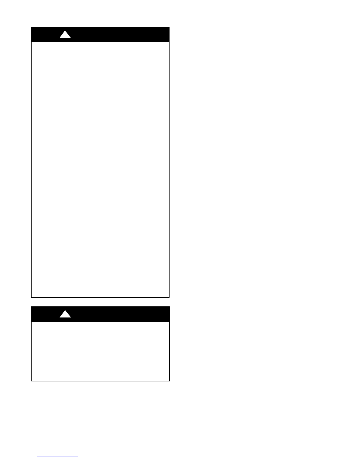
PRE−START−UP/START−UP
!
WARNING
PERSONAL INJURY HAZARD
Failure to follow this warning could result in personal
injury or death.
1. Follow recognized safety practices and wear
approved Personal Protective Equipment (PPE),
including safety glasses and gloves when
checking or servicing refrigerant system.
2. Do not use a torch to remove any component.
System contains oil and refrigerant under
pressure. To remove a component, wear PPE and
proceed as follows:
a. Shut off all electrical power to unit. Apply
applicable Lock−out/Tagout procedures.
b. Recover refrigerant to relieve all pressure
from system using both high−pressure and
low pressure ports.
c. Do not use a torch. Cut component connec-
tion tubing with tubing cutter and remove
component from unit.
d. Carefully un−sweat remaining tubing stubs
when necessary. Oil can ignite when exposed
to torch flame.
3. Do not operate compressor or provide any electric
power to unit unless compressor terminal cover is
in place and secured.
4. Do not remove compressor terminal cover until
all electrical power is disconnected and approved
Lock−out/Tagout procedures are in place.
5. Relieve all pressure from system before touching
or disturbing anything inside terminal box
whenever refrigerant leak is suspected around
compressor terminals.
6. Never attempt to repair a soldered connection
while refrigerant system is under pressure.
!
WARNING
ELECTRICAL OPERATION HAZARD
Failure to follow this warning result in personal injury
or death.
The unit must be electrically grounded in accordance
with local codes and NEC ANSI/NFPA 70 (American
National Standards Institute/National fire Protection
Association.
Proceed as follows to inspect and prepare the unit for
initial start−up:
1. Remove all access panels.
2. Read and follow instructions on all WARNING,
CAUTION, and INFORMATION labels attached to,
or shipped with, unit.
3. Make the following inspections:
a. Inspect for shipping and handling damages such
as broken lines, loose parts, or disconnected
wires, etc.
b. Inspect for oil at all refrigerant tubing connec-
tions and on unit base. Detecting oil generally
indicates a refrigerant leak. Leak−test all refrigerant tubing connections using electronic leak
detector, halide torch, or liquid−soap solution.
c. Inspect all field−wiring and factory−wiring con-
nections. Be sure that connections are completed
and tight. Be sure that wires are not in contact
with refrigerant tubing or sharp edges.
d. Inspect coil fins. If damaged during shipping and
handling, carefully straighten fins with a fin
comb.
4. Verify the following conditions:
a. Make sure that condenser−fan blade are correctly
positioned in fan orifice. See Condenser−Fan
Adjustment section for more details.
b. Make sure that air filter(s) is in place.
c. Make sure that condensate drain trap is filled
with water to ensure proper drainage.
d. Make sure that all tools and miscellaneous loose
parts have been removed.
START−UP, GENERAL
Unit Preparation
Make sure that unit has been installed in accordance with
installation instructions and applicable codes.
IMPORTANT: Follow the base unit’s start-up sequence
as described in the unit’s installation instructions:
In addition to the base unit start-up, there are a few steps
needed to properly start-up the controls. RTU-OPEN’s
Service Test function should be used to assist in the base
unit start-up and also allows verification of output
operation. Controller configuration is also part of start-up.
This is especially important when field accessories have
been added to the unit. The factory pre-configures options
installed at the factory. There may also be additional
installation steps or inspection required during the start-up
process.
Additional Installation/Inspection
Inspect the field installed accessories for proper
installation, making note of which ones do or do not
require configuration changes. Inspect the RTU-OPEN’s
Alarms for initial insight to any potential issues. Refer to
the following manual: “Controls, Start−up, Operation and
Troubleshooting Instructions.” Inspect the SAT sensor for
relocation as intended during installation. Inspect special
wiring as directed below.
49

Return−Air Filters
Ensure correct filters are installed in unit (see Appendix II
− Physical Data). Do not operate unit without return−air
filters.
Outdoor−Air Inlet Screens
Outdoor−air inlet screen must be in place before operating
unit.
Compressor Mounting
Compressors are internally spring mounted. Do not loosen
or remove compressor hold down bolts.
Internal Wiring
Check all electrical connections in unit control boxes.
Tighten as required.
Refrigerant Service Ports
Each unit system has two 1/4” SAE flare (with check
valves) service ports: one on the suction line, and one on
the compressor discharge line. Be sure that caps on the
ports are tight.
Compressor Rotation
CAUTION
EQUIPMENT DAMAGE HAZARD
Failure to follow this CAUTION could result in
equipment damage.
Scroll compressors can only compress refrigerant if
rotating in the right direction. Reverse rotation for
extended times can result in internal damage to the
compressor. Scroll compressors are sealed units and
cannot be repaired on−site.
6. Replace the compressor if suction/discharge pressures
are not within specifications for the specific compressor.
Cooling
Set space thermostat to OFF position. To start unit, turn on
main power supply. Set system selector switch at COOL
position and fan switch at AUTO. position. Adjust
thermostat to a setting below room temperature.
Compressor starts on closure of contactor.
Check unit charge. Refer to Refrigerant Charge section.
Reset thermostat at a position above room temperature.
Compressor will shut off. Evaporator fan will shut off
after a 30−second delay.
To shut off unit, set system selector switch at OFF
position. Resetting thermostat at a position above room
temperature shuts unit off temporarily until space
temperature exceeds thermostat setting.
NOTE: The default value for the evaporator−fan motor
on/off delay is 45 seconds. The Integrated Gas Unit
Controller (IGC) modifies this value when abnormal limit
switch cycles occur. Based upon unit operating conditions,
the on delay can be reduced to 0 seconds and the off delay
can be extended to 180 seconds. When one flash of the
LED is observed, the evaporator−fan on/off delay has
been modified.
Ventilation (Continuous Fan)
Set fan and system selector switches at ON and OFF
positions, respectively. Evaporator fan operates
continuously to provide constant air circulation. When the
evaporator−fan selector switch is turned to the OFF
position, there is a 30−second delay before the fan turns
off.
NOTE: When the compressor is rotating in the wrong
direction, the unit will make an elevated level of noise
and will not provide cooling.
On 3−phase units with scroll compressors, it is important
to be certain compressor is rotating in the proper
direction. To determine whether or not compressor is
rotating in the proper direction:
1. Connect service gauges to suction and discharge pressure fittings.
2. Energize the compressor.
3. The suction pressure should drop and the discharge
pressure should rise, as is normal on any start−up.
If the suction pressure does not drop and the discharge
pressure does not rise to normal levels:
1. Note that the evaporator fan is probably also rotating
in the wrong direction.
2. Turn off power to the unit and install lockout tag.
3. Reverse any two of the unit power leads.
4. Reapply electrical power to the compressor.
5. The suction pressure should drop, and the discharge
pressure should rise, which is normal for scroll compressors on start−up.
START−UP, PREMIERLINK] CONTROLS
!
WARNING
ELECTRICAL OPERATION HAZARD
Failure to follow this warning could result in personal
injury or death.
The unit must be electrically grounded in accordance
with local codes and NEC ANSI/NFPA 70 (American
National Standards Institute/National Fire Protection
Association.)
Use the Carrier network communication software to start
up and configure the PremierLink controller.
Changes can be made using the ComfortWORKS
software, ComfortVIEW software, Network Service
Tool, System Pilot device, or Touch Pilot device. The
System Pilot and Touch Pilot are portable interface
devices that allow the user to change system set−up and
setpoints from a zone sensor or terminal control module.
During start−up, the Carrier software can also be used to
verify communication with PremierLink controller.
50

NOTE: All set−up and setpoint configurations are factory
set and field−adjustable.
For specific operating instructions, refer to the literature
provided with user interface software.
NOTICE
SET−UP INSTRUCTIONS
All set−up and set point configurations are factory set
and field−adjustable.
Refer to the PremierLinkt Installation, Start−Up and
Configuration Instructions for specific operating
instructions for the controller. Have a copy of this
manual available at unit start−up.
Perform System Check−Out
1. Check correctness and tightness of all power and
communication connections.
2. At the unit, check fan and system controls for proper
operation.
3. At the unit, check electrical system and connections
of any optional electric reheat coil.
4. Check to be sure the area around the unit is clear of
construction dirt and debris.
5. Check that final filters are installed in the unit. Dust
and debris can adversely affect system operation.
6. Verify that the PremierLink controls are properly connected to the CCN bus.
START−UP, RTU−OPEN CONTROLS
NOTICE
SET−UP INSTRUCTIONS
Refer to the following manuals for additional
installation, wiring and troubleshooting information
for the RTU−OPEN Controller.: “Controls, Start−up,
Operation and Troubleshooting Instructions,” “RTU
Open Installation and Start−up Guide” and
“RTU−Open Integration Guide”. Have a copy of these
manuals available at unit start−up.
FASTENER TORQUE VALUES
Table 11 – Torque Values
Supply fan motor mounting
Supply fan motor adjustment plate
Motor pulley setscrew
Fan pulley setscrew
Blower wheel hub setscrew
Bearing locking collar setscrew 50 in-lbs (6.2 Nm) — 60 in-lbs (6.8 Nm)
Compressor mounting bolts 65 in-lbs (7.3 Nm) — 75 in-lbs (8.5Nm)
Condenser fan motor mounting bolts
Condenser fan hub setscrew
Serial Number Format
POSITION NUMBER 1 2 3 4 5 6 7 8 9 10
TYPICAL 4 8 0 8 G 1 2 3 4 5
POSITION DESIGNATES
1−2 Week of manufacture (fiscal calendar)
3−4 Year of manufacture (“08” = 2008)
5 Manufacturing location (G = ETP, Texas, USA)
6−10 Sequential number
120 in-lbs (13.6 Nm) ± 12 in-lbs (1.4Nm)
120 in-lbs (13.6 Nm) ± 12 in-lbs (1.4Nm)
72 in-lbs (8.1 Nm) ± 5 in-lbs (0.6 Nm)
72 in-lbs (8.1 Nm) ± 5 in-lbs (0.6 Nm)
72 in-lbs (8.1 Nm) ± 5 in-lbs (0.6 Nm)
20 in-lbs (2.3 Nm) ± 2 in-lbs 0.2 Nm)
84 in-lbs (9.5 Nm) ± 12 in-lbs (1.4 Nm)
51

APPENDIX I. MODEL NUMBER NOMENCLATURE
Position:
1234567891011 12 13 14 15 16
17
18
Example:
50TC- D24A3A5- 0A0A0
Unit Heat Type
50 - Elect. Heat Pkgd Rooftop
Model Series - WeatherMaker™
TC - Standard Efficiency
ElectricHeat Options
- = Standard (No Electric Heat)
A = Low Electric Heat
B = Medium Electric Heat
C = High Electric Heat
Refrig. Systems Options
D = Two stage cooling
E = Two stage cooling models with Humidi-MiZer
Cooling Tons
17/18 = 15 tons
20/21 = 17.5 tons
24/25 = 20 tons
28/29 = 25 tons
30 = 27.5 tons
Sens or Options
A = None
B = RA Smoke Detector
C = SA Smoke Detector
D = RA + SA Smoke Detector
E = CO
F = RA Smoke Detector + CO
G = SA Smoke Detector + CO
H = RA + SA Smoke Detector + CO
Sensor
2
2
2
2
Indoor Fan Options & Air Flow Configuration
1 = Standard Static / Vertical Supply, Return Air Flow
2 = Medium Static Option - Belt Drive
3 = High Static / Vertical Supply, Return Air Flow
B = Med Static High Eff Motor / Vert Supply, Return Air Flow
C = High Static High Eff Motor / Vert Supply, Return Air Flow
2 = Medium Static Option - Belt Drive
5 = Standard Static / Horizontal Supply, Return Air Flow
6 = Medium Static / Horizontal Supply, Return Air Flow
7 = High Static / Horizontal Supply, Return Air Flow
F = Med Static Hi Eff Motor / Horizontal Supply, Return Air Flow
G = High Static High Eff Motor / Horiz Supply, Return Air Flow
Factory Assigned
0 = Standard
3 = CA Seismic Compliant
Electrical Options
A = None
B = HACR Breaker
C = Non-Fused Disconnect
G = 2-Speed Indoor Fan (VFD) Controller
J = 2 Speed Fan Controller &
Non-Fused Disconnect
Service Options
0 = None
1 = Unpowered Convenience Outlet
2 = Powered Convenience Outlet
3 = Hinged Panels
4 = Hinged Panels and
Unpowered Convenience Outlet
5 = Hinged Panels and
Powered Convenience Outlet
C = Foil Faced Insulation
Intake / Exhaust Options
A = None
B = Temperature Economizer w/ Barometric Relief
F = Enthalpy Economizer w/ Barometric Relief
K = 2-Position Damper
U =
Temp Ultra Low Leak Economizer w/ Baro Relief
V = Temp. Ultra Low LEak Econo w/PE (cent) Vert
W =
Enthalpy Ultra Low Leak Economizer w/ Baro Relief
X = Enthalpy Ultra Low Leak Econ w/P (cent) Vertical Air Only
Base Unit Controls
0 = Electromechanical Controls. Can be used with
W7212 EconoMi$er IV (Non-Fault Detection
and Diagnostic)
1 = PremierLink Controller
2 = RTU Open Multi-Protocol Controller
6 = Electro-mechanical Controls. Can be used with
W7220 EconoMi$er X (with Fault Detection
and Diagnostic)
D = ComfortLink Controls
Coil Options (RTPF) (Outdoor - Indoor - Hail Guard)
A = Al/Cu - Al/Cu
B = Precoat Al/Cu - Al/Cu
C = E-coat Al/Cu - Al/Cu
D = E-coat Al/Cu - E-coat Al/Cu
E = Cu/Cu - Al/Cu
F = Cu/Cu - Cu/Cu
M = Al/Cu -Al/Cu — Louvered Hail Guard
N = Precoat Al/Cu - Al/Cu — Louvered Hail Guard
P = E-coat Al/Cu - Al/Cu — Louvered Hail Guard
Q = E-coat Al/Cu - E-coat Al/Cu — Louvered Hail Guard
R = Cu/Cu - Al/Cu — Louvered Hail Guard
S = Cu/Cu - Cu/Cu — Louvered Hail Guard
Coil Options – Novation (Outdoor - Indoor - Hail Guard)
G = Al/Al - Al/Cu
H = Al/Al - Cu/Cu
J = Al/Al - E-coat Al/Cu
K = E-coat Al/Al - Al/Cu
L = E-coat Al/Al - E-coatAl/Cu
T = Al/Al - Al/Cu — Louvered Hail Guard
U = Al/Al - Cu/Cu — Louvered Hail Guard
V = Al/Al - E-coat Al/Cu — Louvered Hail Guard
Design Revision
- Factory Design Revision
Voltage
1 = 575/3/60
5 = 208-230/3/60
6 = 460/3/60
C150380
52

APPENDIX II. PHYSICAL DATA
Table 12 – PHYSICAL DATA − VERTICAL (COOLING) 15 − 27.5 TONS
RTPF (Round Tube/Plate Fin Coil Design)
50TC-D17 50TC-E17 50TC-D20 50TC-E20
Refrigeration System RTPF RTPF RTPF RTPF
# Circuits / # Comp. / Type 2 / 2 / Scroll 2 / 2 / Scroll 2 / 2 / Scroll 2 / 2 / Scroll
R-410a charge A/B (lbs) 16.3/17.5 25.9/25.7 16.3/17.5 25.9/25.7
Metering device Acutrol TXV Acutrol TXV
High-press. Trip / Reset (psig) 630 / 505 630 / 505 630 / 505 630 / 505
Low-press. Trip / Reset (psig) 54 / 117 27 / 44 54 / 117 27 / 44
Evap. Coil
Material Cu / Al Cu / Al Cu / Al Cu / Al
Tube Diameter 3/8" 3/8" 3/8" 3/8"
Rows / FPI 4 / 15 4 / 15 4 / 15 4 / 15
total face area (ft2) 22.00 22.00 22.00 22.00
Condensate drain conn. size 3/4" 3/4" 3/4" 3/4"
Humidimizer Coil
Material n/a Cu / Al n/a Cu / Al
Tube Diameter n/a 3/8" n/a 3/8"
Rows / FPI n/a 1 / 17 n/a 1 / 17
total face area (ft2) n/a 22.00 n/a 22.00
Evap. fan and motor
VERTICAL
Motor Qty / Belt Qty / Driver Type 1 / 1 / Belt 1 / 1 / Belt 1 / 1 / Belt 1 / 1 / Belt
Standard
Static
Max BHP 2.2 2.2 3.3 3.3
RPM range 514-680 514-680 622-822 622-822
motor frame size 56 56 56 56
Fan Qty / Type 2 / Centrifugal 2 / Centrifugal 2 / Centrifugal 2 / Centrifugal
Fan Diameter (in) 15 x 15 15 x 15 15 x 15 15 x 15
Medium
Static
High
Static
High
Static-
High
Efficiency
Motor Qty / Belt Qty / Driver Type 1 / 1 / Belt 1 / 1 / Belt 1 / 1 / Belt 1 / 1 / Belt
Max BHP 3.3 3.3 4.9 4.9
RPM range 679-863 679-863 713-879 713-879
motor frame size 56 56 56 56
Fan Qty / Type 2 / Centrifugal 2 / Centrifugal 2 / Centrifugal 2 / Centrifugal
Fan Diameter (in) 15 x 15 15 x 15 15 x 15 15 x 15
Motor Qty / Belt Qty / Driver Type 1 / 1 / Belt 1 / 1 / Belt n/a n/a
Max BHP 4.9 4.9 n/a n/a
RPM range 826-1009 826-1009 n/a n/a
motor frame size 56 56 n/a n/a
Fan Qty / Type 2 / Centrifugal 2 / Centrifugal n/a n/a
Fan Diameter (in) 15 x 15 15 x 15 n/a n/a
Motor Qty / Belt Qty / Driver Type n/a n/a 1 / 1 / Belt 1 / 1 / Belt
Max BHP (208/230/460/575v) n/a n/a 6.5/ 6.9/ 7.0/ 8.3 6.5/ 6.9/ 7.0/ 8.3
RPM range n/a n/a 882-1078 882-1078
motor frame size n/a n/a 184T 184T
Fan Qty / Type n/a n/a 2 / Centrifugal 2 / Centrifugal
Fan Diameter (in) n/a n/a 15 x 15 15 x 15
53

APPENDIX II. PHYSICAL DATA (CONT)
Table 12 - PHYSICAL DATA − VERTICAL (cont) (COOLING) 15 - 27.5 TONS
RTPF (Round Tube/Plate Fin Coil Design)
50TC-D24 50TC-E24 50TC-D28 50TC-E28 50TC-D30
Refrigeration System RTPF RTPF RTPF RTPF RTPF
# Circuits / # Comp. / Type 2 / 2 / Scroll 2 / 2 / Scroll 2 / 2 / Scroll 2 / 2 / Scroll 2 / 2 / Scroll
R-410a charge A/B (lbs) 20.6/14.7 27.9/20.5 19.8/ 20.4 27.9/ 28.9 27.0/ 28.5
Metering device Acutrol TXV Acutrol TXV Acutrol
High-press. Trip / Reset (psig) 630 / 505 630 / 505 630 / 505 630 / 505 630 / 505
Low-press. Trip / Reset (psig) 54 / 117 27 / 44 54 / 117 27 / 44 54 / 117
Evap. Coil
Material Cu / Al Cu / Al Cu / Al Cu / Al Cu / Al
Tube Diameter 3/8" 3/8" 3/8" 3/8" 3/8"
Rows / FPI 4 / 15 4 / 15 4 / 15 4 / 15 4 / 15
total face area (ft2) 22.00 22.00 23.11 23.11 26
Condensate drain conn. size 3/4" 3/4" 3/4" 3/4" 3/4"
Humidimizer Coil
Material n/a Cu / Al n/a Cu / Al n/a
Tube Diameter n/a 3/8" n/a 3/8" n/a
Rows / FPI n/a 1 / 17 n/a 1 / 17 n/a
total face area (ft2) n/a 22.00 n/a 23.11 n/a
Evap. fan and motor
VERTICAL
Standard
Static
Motor Qty / Belt Qty
/ Driver Type
Max BHP 4.9 4.9 4.9 4.9 n/a
RPM range 690-863 690-863 717-911 717-911 n/a
motor frame size 56 56 56 56 n/a
Fan Qty / Type 2 / Centrifugal 2 / Centrifugal 2 / Centrifugal 2 / Centrifugal n/a
Fan Diameter (in) 15 x 15 15 x 15 15 x 15 15 x 15 n/a
1 / 1 / Belt 1 / 1 / Belt 1 / 1 / Belt 1 / 1 / Belt n/a
Standard
Static -
High
Efficiency
Medium
Static -
High
Efficiency
High
Static-
High
Efficiency
Motor Qty / Belt Qty
/ Driver Type
Max BHP n/a n/a n/a n/a 6.5/ 6.9/ 7.0/ 8.3
RPM range n/a n/a n/a n/a 751-954
motor frame size n/a n/a n/a n/a 184T
Fan Qty / Type n/a n/a n/a n/a 2 / Centrifugal
Fan Diameter (in) n/a n/a n/a n/a 15 x 15
Motor Qty / Belt Qty
/ Driver Type
Max BHP
(208/230/460/575v)
RPM range 835-1021 835-1021 913-1116 913-1116 920-1190
motor frame size 184T 184T 184T 184T 213T
Fan Qty / Type 2 / Centrifugal 2 / Centrifugal 2 / Centrifugal 2 / Centrifugal 2 / Centrifugal
Fan Diameter (in) 15 x 15 15 x 15 15 x 15 15 x 15 15 x 15
Motor Qty / Belt Qty
/ Driver Type
Max BHP
(208/230/460/575v)
RPM range 941-1176 941-1176 941-1176 941-1176 1116-1400
motor frame size 213T 213T 213T 213T 215T
Fan Qty / Type 2 / Centrifugal 2 / Centrifugal 2 / Centrifugal 2 / Centrifugal 2 / Centrifugal
Fan Diameter (in) 15 x 15 15 x 15 15 x 15 15 x 15 15 x 15
n/a n/a n/a n/a 1 / 1 / Belt
1 / 1 / Belt 1 / 1 / Belt 1 / 1 / Belt 1 / 1 / Belt 1 / 1 / Belt
6.5/ 6.9/ 7.0/ 8.3 6.5/ 6.9/ 7.0/ 8.3 6.5/ 6.9/ 7.0/ 8.3 6.5/ 6.9/ 7.0/ 8.3 10.5/11.9/11.9/11
1 / 1 / Belt 1 / 1 / Belt 1 / 1 / Belt 1 / 1 / Belt 1 / 2 Belt
10.5/11.9/11.9/11 10.5/11.9/11.9/11 10.5/11.9/11.9/11 10.5/11.9/11.9/11 11.9/12.9/12.9/14.1
54

APPENDIX II. PHYSICAL DATA (CONT)
Table 12 - PHYSICAL DATA − VERTICAL (cont) (COOLING) 15-27.5 TONS
RTPF (Round Tube/Plate Fin Coil Design)
50TC-D17 50TC-E17 50TC-D20 50TC-E20 50TC-D24 50TC-E24 50TC-D28 50TC-E28 50TC-D30
Cond. Coil (Circuit A)
Coil type RTPF RTPF RTPF RTPF RTPF RTPF RTPF RTPF RTPF
Coil Length (in) 70 70 70 70 82 82 75 75 95
Coil Height (in) 44 44 44 44 44 44 52 52 52
Rows / FPI 2 /17 2 /17 2 /17 2 /17 2 /17 2 /17 2 /17 2 /17 2 /17
total face area (ft2) 21.4 21.4 21.4 21.4 25.1 25.1 27.1 27.1 34.3
Cond. Coil (Circuit B)
Coil type RTPF RTPF RTPF RTPF RTPF RTPF RTPF RTPF RTPF
Coil Length (in) 70 70 70 70 57 57 75 75 95
Coil Height (in) 44 44 44 44 44 44 52 52 52
Rows / FPI 2 /17 2 /17 2 /17 2 /17 2 /17 2 /17 2 /17 2 /17 2 /17
total face area (ft2) 21.4 21.4 21.4 21.4 17.4 17.4 27.1 27.1 34.3
Cond. fan / motor
Qty / Motor drive type 3 / direct 3 / direct 3 / direct 3 / direct 4 / direct 4 / direct 4 / direct 4 / direct 6 / direct
Motor HP / RPM 1/4 / 1100 1/4 / 1100 1/4 / 1100 1/4 / 1100 1/4 / 1100 1/4 / 1100 1/4 / 1100 1/4 / 1100 1/4 / 1100
Fan diameter (in) 22 22 22 22 22 22 22 22 22
Filters
RA Filter # / size (in)
OA inlet screen # / size
(in)
6 / 20 x 25
x 2
4 / 16 x 25
x 1
6 / 20 x 25
x 2
4 / 16 x 25
x 1
6 / 20 x 25
x 2
4 / 16 x 25
x 1
6 / 20 x 25
x 2
4 / 16 x 25
x 1
6 / 20 x 25
x 2
4 / 16 x 25
x 1
6 / 20 x 25
x 2
4 / 16 x 25
x 1
9 / 16 x 25
x 2
4 / 16 x 25
x 1
9 / 16 x 25
x 2
4 / 16 x 25
x 1
9 / 16 x 25
x 2
4 / 16 x 25
x 1
55

APPENDIX II. PHYSICAL DATA (CONT)
Table 12 - PHYSICAL DATA − VERTICAL (cont) (COOLING) 15-27.5 TONS
Novation - All Aluminum Coil Design
50TC*17 50TC*20 50TC*24 50TC*28
Refrigeration System MCHX MCHX MCHX MCHX
# Circuits / # Comp. / Type 2 / 2 / Scroll 2 / 2 / Scroll 2 / 2 / Scroll 2 / 2 / Scroll
R-410a charge A/B (lbs) 9.5/12.0 9.5/12.0 14.4/12.5 12.5/13.0
Metering device Acutrol Acutrol Acutrol Acutrol
High-press. Trip / Reset (psig) 630 / 505 630 / 505 630 / 505 630 / 505
Low-press. Trip / Reset (psig) 54 / 117 54 / 117 54 / 117 54 / 117
Evap. Coil
Material Cu / Al Cu / Al Cu / Al Cu / Al
Tube Diameter 3/8" 3/8" 3/8" 3/8"
Rows / FPI 4 / 15 4 / 15 4 / 15 4 / 15
total face area (ft2) 19.56 19.56 22.00 23.11
Condensate drain conn. size 3/4" 3/4" 3/4" 3/4"
Evap. fan and motor
VERTICAL
Motor Qty / Belt Qty /
Standard
Static
Motor Qty / Belt Qty /
Medium
Static
Motor Qty / Belt Qty /
High
Static
Motor Qty / Belt Qty /
Medium
Static -
High
Efficiency
Motor Qty / Belt Qty /
High
Static-
High
Efficiency
Driver Type
Max BHP 2.2 3.3 4.9 4.9
RPM range 514-680 622-822 690-863 717-911
motor frame size 56 56 56 56
Fan Qty / Type 2 / Centrifugal 2 / Centrifugal 2 / Centrifugal 2 / Centrifugal
Fan Diameter (in) 15 x 15 15 x 15 15 x 15 15 x 15
Driver Type
Max BHP 3.3 4.9 6.5 6.5
RPM range 679-863 713-879 835-1021 913-1116
motor frame size 56 56 184T 184T
Fan Qty / Type 2 / Centrifugal 2 / Centrifugal 2 / Centrifugal 2 / Centrifugal
Fan Diameter (in) 15 x 15 15 x 15 15 x 15 15 x 15
Driver Type
Max BHP 4.9 6.5 8.7 8.7
RPM range 826-1009 882-1078 941-1176 941-1176
motor frame size 56 184T 213T 213T
Fan Qty / Type 2 / Centrifugal 2 / Centrifugal 2 / Centrifugal 2 / Centrifugal
Fan Diameter (in) 15 x 15 15 x 15 15 x 15 15 x 15
Driver Type
Max BHP
(208/230/460/575v)
RPM range n/a n/a 835-1021 913-1116
motor frame size n/a n/a 184T 184T
Fan Qty / Type n/a n/a 2 / Centrifugal 2 / Centrifugal
Fan Diameter (in) n/a n/a 15 x 15 15 x 15
Driver Type
Max BHP
(208/230/460/575v)
RPM range n/a 882-1078 941-1176 941-1176
motor frame size n/a 184T 213T 213T
Fan Qty / Type n/a 2 / Centrifugal 2 / Centrifugal 2 / Centrifugal
Fan Diameter (in) n/a 15 x 15 15 x 15 15 x 15
1 / 1 Belt 1 / 1 Belt 1 / 1 Belt 1 / 1 Belt
1 / 1 Belt 1 / 1 Belt 1 / 1 Belt 1 / 1 Belt
1 / 1 Belt 1 / 1 Belt 1 / 1 Belt 1 / 1 Belt
n/a n/a 1 / 1 Belt 1 / 1 Belt
n/a n/a 6.5/ 6.9/ 7.0/ 8.3 6.5/ 6.9/ 7.0/ 8.3
n/a 1 / 1 Belt 1 / 1 Belt 1 / 1 Belt
n/a 6.5/ 6.9/ 7.0/ 8.3 10.5/11.9/11.9/11 10.5/11.9/11.9/11
56

APPENDIX II. PHYSICAL DATA (CONT)
Table 12 - PHYSICAL DATA − VERTICAL (cont) (COOLING) 15-27.5 TONS
Novation - All Aluminum Coil Design
50TC*17 50TC*20 50TC*24 50TC*28
Cond. Coil (Circuit A)
Coil type Novation Novation Novation Novation
Coil Length (in) 70 70 82 75
Coil Height (in) 44 44 44 52
Number of Passes l Rows
total face area (ft2) 21.4 21.4 25.1 27.1
Cond. Coil (Circuit B)
Coil Length (in) 70 70 57 75
Coil Height (in) 44 44 44 52
total face area (ft2) 21.4 21.4 17.4 27.1
Cond. fan / motor
Qty / Motor drive type 3 / direct 3 / direct 4 / direct 4 / direct
Motor HP / RPM 1/4 / 1100 1/4 / 1100 1/4 / 1100 1/4 / 1100
Fan diameter (in) 22 22 22 22
Filters
RA Filter # / size (in) 6 / 20 x 25 x 2 6 / 20 x 25 x 2 6 / 20 x 25 x 2 9 / 16 x 25 x 2
OA inlet screen # / size (in) 4 / 16 x 25 x 1 4 / 16 x 25 x 1 4 / 16 x 25 x 1 4 / 16 x 25 x 1
/ FPI
Coil type Novation Novation Novation Novation
Rows / FPI 2 2 2 2
2 2 2 2
57

APPENDIX II. PHYSICAL DATA (CONT)
TABLE 13 – PHYSICAL DATA − HORIZONTAL (COOLING) 15−25 TONS
RTPF (Round Tube/Plate Fin Coil Design)
50TC-D18 50TC-E18 50TC-D21 50TC-E21
Refrigeration System
# Circuits / # Comp. / Type 2 / 2 / Scroll 2 / 2 / Scroll 2 / 2 / Scroll 2 / 2 / Scroll
R-410a charge A/B (lbs) 17/16.4 24.5/25.7 17.5/16.8 25.5/25.5
Metering device TXV TXV TXV TXV
High-press. Trip / Reset (psig) 630 / 505 630 / 505 630 / 505 630 / 505
Low-press. Trip / Reset (psig) 54 / 117 27 / 44 54 / 117 27 / 44
Material Cu / Al Cu / Al Cu / Al Cu / Al
Tube Diameter 3/8" RTPF 3/8" RTPF 3/8" RTPF 3/8" RTPF
Rows / FPI 4 / 15 4 / 15 4 / 15 4 / 15
total face area (ft2) 22 22 22 22
Condensate drain conn. size 3/4" 3/4" 3/4" 3/4"
Humidimizer Coil
Material n/a Cu / Al n/a Cu / Al
Tube Diameter n/a 3/8" RTPF n/a 3/8" RTPF
Rows / FPI n/a 1 / 17 n/a 1 / 17
total face area (ft2) n/a 22 n/a 22
Evap. fan and motor
HORIZONTAL
Motor Qty / Belt Qty / Driver Type 1/1/ Belt 1/1/ Belt 1/1/ Belt 1/1/ Belt
Max BHP 2.2 2.2 3.3 3.3
Standard
Static
Motor Qty / Belt Qty / Driver Type 1/1/ Belt 1/1/ Belt 1/1/ Belt 1/1/ Belt
Medium
Static
Motor Qty / Belt Qty / Driver Type 1/1/ Belt 1/1/ Belt n/a n/a
High
Static
Motor Qty / Belt Qty / Driver Type n/a n/a 1/1/ Belt 1/1/ Belt
High
Static-
High Eff
RPM range 514-680 514-680 622-822 622-822
motor frame size 56 56 56 56
Fan Qty / Type 2 / Centrifugal 2 / Centrifugal 2 / Centrifugal 2 / Centrifugal
Fan Diameter (in) 18 x 15/15 X 11 18 x 15/15 X 11 18 x 15/15 X 11 18 x 15/15 X 11
Max BHP 3.3 3.3 4.9 4.9
RPM range 614-780 614-780 713-879 713-879
motor frame size 56 56 56 56
Fan Qty / Type 2 / Centrifugal 2 / Centrifugal 2 / Centrifugal 2 / Centrifugal
Fan Diameter (in) 18 x 15/15 X 11 18 x 15/15 X 11 18 x 15/15 X 11 18 x 15/15 X 11
Max BHP 4.9 4.9 n/a n/a
RPM range 746-912 746-912 n/a n/a
motor frame size 56 56 n/a n/a
Fan Qty / Type 2 / Centrifugal 2 / Centrifugal n/a n/a
Fan Diameter (in) 18 x 15/15 X 11 18 x 15/15 X 11 n/a n/a
Max BHP n/a n/a 6.5/ 6.9/ 7.0/ 8.3 6.5/ 6.9/ 7.0/ 8.3
RPM range n/a n/a 882-1078 882-1078
motor frame size n/a n/a 184T 184T
Fan Qty / Type n/a n/a 2 / Centrifugal 2 / Centrifugal
Fan Diameter (in) n/a n/a 18 x 15/15 X 11 18 x 15/15 X 11
58

APPENDIX II. PHYSICAL DATA (CONT)
Table 13 PHYSICAL DATA − HORIZONTAL (cont) (COOLING) 15−25 TONS
RTPF (Round Tube/Plate Fin Coil Design)
50TC-D25 50TC-E25 50TC-D29 50TC-E29
Refrigeration System
# Circuits / # Comp. / Type 2 / 2 / Scroll 2 / 2 / Scroll 2 / 2 / Scroll 2 / 2 / Scroll
R-410a charge A/B (lbs) 23.8/23.1 30.0/30.7 24.9/27.7 35.1/35.4
Metering device TXV TXV TXV TXV
High-press. Trip / Reset (psig) 630 / 505 630 / 505 630 / 505 630 / 505
Low-press. Trip / Reset (psig) 54 / 117 27 / 44 54 / 117 27 / 44
Material Cu / Al Cu / Al Cu / Al Cu / Al
Tube Diameter 3/8" RTPF 3/8" RTPF 3/8" RTPF 3/8" RTPF
Rows / FPI 4 / 15 4 / 15 4 / 15 4 / 15
total face area (ft2) 26 26 26 26
Condensate drain conn. size 3/4" 3/4" 3/4" 3/4"
Humidimizer Coil
Material n/a Cu / Al n/a Cu / Al
Tube Diameter n/a 3/8" RTPF n/a 3/8" RTPF
Rows / FPI n/a 1 / 17 n/a 1 / 17
total face area (ft2) n/a 26 n/a 26
Evap. fan and motor
HORIZONTAL
Motor Qty / Belt Qty / Driver Type 1/1/ Belt 1/1/ Belt 1/1/ Belt 1/1/ Belt
Max BHP 4.9 4.9 4.9 4.9
Standard Static
Motor Qty / Belt Qty / Driver Type 1/1/ Belt 1/1/ Belt 1/1/ Belt 1/1/ Belt
Medium Static
- High Eff.
Motor Qty / Belt Qty / Driver Type 1/1/ Belt 1/1/ Belt 1/1/ Belt 1/1/ Belt
High Static-
High Eff.
RPM range 690-863 690-863 647-791 647-791
motor frame size 56 56 56 56
Fan Qty / Type 2 / Centrifugal 2 / Centrifugal 2 / Centrifugal 2 / Centrifugal
Fan Diameter (in) 18 x 15/15 X 11 18 x 15/15 X 11 18 x 15/15 X 11 18 x 15/15 X 11
Max BHP 6.5/ 6.9/ 7.0/ 8.3 6.5/ 6.9/ 7.0/ 8.3 6.5/ 6.9/ 7.0/ 8.3 6.5/ 6.9/ 7.0/ 8.3
RPM range 835-1021 835-1021 755-923 755-923
motor frame size 184T 184T 184T 184T
Fan Qty / Type 2 / Centrifugal 2 / Centrifugal 2 / Centrifugal 2 / Centrifugal
Fan Diameter (in) 18 x 15/15 X 11 18 x 15/15 X 11 18 x 15/15 X 11 18 x 15/15 X 11
Max BHP 10.5/11.9/11.9/11 10.5/11.9/11.9/11 10.5/11.9/11.9/11 10.5/11.9/11.9/11
RPM range 941-1176 941-1176 827-1010 827-1010
motor frame size 213T 213T 213T 213T
Fan Qty / Type 2 / Centrifugal 2 / Centrifugal 2 / Centrifugal 2 / Centrifugal
Fan Diameter (in) 18 x 15/15 X 11 18 x 15/15 X 11 18 x 15/15 X 11 18 x 15/15 X 11
59

APPENDIX II. PHYSICAL DATA (CONT)
Table 13 PHYSICAL DATA − HORIZONTAL (cont) (COOLING) 15−25 TONS
RTPF (Round Tube/Plate Fin Coil Design)
50TC-D18 50TC-E18 50TC-D21 50TC-E21 50TC-D25 50TC-E25 50TC-D29 50TC-E29
Cond. Coil (Circuit A)
Coil type RTPF RTPF RTPF RTPF RTPF RTPF RTPF RTPF
Coil Length (in) 70 70 72 72 82 82 95 95
Coil Height (in) 44 44 44 44 52 52 52 52
Rows / FPI 2 /17 2 /17 2 /17 2 /17 2 /17 2 /17 2 /17 2 /17
total face area (ft2) 21.4 21.4 22.0 22.0 29.6 29.6 34.3 34.3
Cond. Coil (Circuit B)
Coil type RTPF RTPF RTPF RTPF RTPF RTPF RTPF RTPF
Coil Length (in) 70 70 64 64 80 80 95 95
Coil Height (in) 44 44 44 44 52 52 52 52
Rows / FPI 2 /17 2 /17 2 /17 2 /17 2 /17 2 /17 2 /17 2 /17
total face area (ft2) 21.4 21.4 19.5 19.5 29.6 29.6 34.3 34.3
Cond. fan / motor
Qty / Motor drive type 3 / direct 3 / direct 4 / direct 4 / direct 4/ direct 4/ direct 6 / direct 6 / direct
Motor HP / RPM 1/4 / 1100 1/4 / 1100 1/4 / 1100 1/4 / 1100 1/4 / 1100 1/4 / 1100 1/4 / 1100 1/4 / 1100
Fan diameter (in) 22 22 22 22 22 22 22 22
Filters
RA Filter # /
size (in)
OA inlet screen # /
size (in)
6 /
20 x 25 x 2
4 /
16 x 25 x 1
6 /
20 x 25 x 2
4 /
16 x 25 x 1
6 /
20 x 25 x 2
4 /
16 x 25 x 1
6 /
20 x 25 x 2
4 /
16 x 25 x 1
9 /
16 x 25 x 2
4 /
16 x 25 x 1
9 /
16 x 25 x 2
4 /
16 x 25 x 1
9 /
16 x 25 x 2
4 /
16 x 25 x 1
9 /
16 x 25 x 2
4 /
16 x 25 x 1
60

APPENDIX III. FAN PERFORMANCE
Table 14 – 50TC*D17 VERTICAL SUPPLY / RETURN 15 TON
Available External Static Pressure (in. wg)
CFM
4500 436 0.60 530 0.90 611 1.22 684 1.57 751 1.94
4900 456 0.71 546 1.03 625 1.37 695 1.73 760 2.12
5250 473 0.83 560 1.16 637 1.51 706 1.89 770 2.30
5600 491 0.95 575 1.30 650 1.67 717 2.07 780 2.48
6000 513 1.11 593 1.48 665 1.87 731 2.28 792 2.71
6400 534 1.29 611 1.68 681 2.09 745 2.52 805 2.97
6750 553 1.46 628 1.87 696 2.29 758 2.74 817 3.20
7100 573 1.65 645 2.07 711 2.51 772 2.98 829 3.46
7500 595 1.88 665 2.33 729 2.79 788 3.27 844 3.77
CFM
4500 812 2.33 869 2.74 924 3.17 975 3.62 1024 4.08
4900 821 2.53 877 2.95 931 3.40 981 3.86 1030 4.34
5250 829 2.72 885 3.16 938 3.61 988 4.09 1036 4.57
5600 838 2.92 893 3.37 945 3.84 994 4.33 1042 4.83
6000 849 3.17 903 3.63 954 4.12 1003 4.62 1050 5.14
6400 861 3.43 914 3.92 964 4.42 1012 4.94 1058 5.47
6750 872 3.69 924 4.18 973 4.70 1021 5.23 1066 5.78
7100 883 3.95 934 4.47 983 5.00 1030 5.54 ---- ---7500 897 4.28 947 4.81 995 5.36 1041 5.92 ---- ----
Std Static Motor and Drive - 514-680 RPM, Max BHP 2.29 Medium Static Motor and Drive - 679-863 RPM, Max BHP 3.3
High Static Motor and Drive - 826-1009 RPM, Max BHP 4.9 ---- Outside operating range
Boldface - Field Supplied Drive ITALIC - Field Supplied Motor and Drive
0.2 0.4 0.6 0.8 1.0
RPM BHP RPM BHP RPM BHP RPM BHP RPM BHP
Available External Static Pressure (in. wg)
1.2 1.4 1.6 1.8 2.0
RPM BHP RPM BHP RPM BHP RPM BHP RPM BHP
Table 15 – 50TC*D20 VERTICAL SUPPLY / RETURN 17.5 TON
Available External Static Pressure (in. wg)
CFM
5250 541 1.08 618 1.42 688 1.79 754 2.19 817 2.62
5700 573 1.31 645 1.67 712 2.06 775 2.48 835 2.93
6100 602 1.55 670 1.93 734 2.34 795 2.77 852 3.23
6500 631 1.81 696 2.21 757 2.64 815 3.09 871 3.57
7000 668 2.19 729 2.61 787 3.06 843 3.53 896 4.03
7500 706 2.62 763 3.06 819 3.54 871 4.03 922 4.55
7900 736 3.00 791 3.47 844 3.96 895 4.47 944 5.00
8300 767 3.42 819 3.90 870 4.41 919 4.94 967 5.49
8750 801 3.94 852 4.44 900 4.97 948 5.52 993 6.09
CFM
5250 876 3.08 932 3.56 986 4.07 1038 4.60 1088 5.15
5700 892 3.40 946 3.90 998 4.42 1049 4.96 1097 5.52
6100 907 3.72 960 4.23 1011 4.76 1060 5.31 1107 5.89
6500 924 4.07 975 4.59 1025 5.13 1072 5.70 1119 6.28
7000 947 4.55 996 5.09 1044 5.65 1090 6.23 1135 6.83
7500 971 5.08 1019 5.64 1064 6.22 1109 6.82 1152 7.44
7900 992 5.55 1038 6.13 1082 6.72 1126 7.34 ---- ---8300 1013 6.06 1057 6.65 1101 7.26 ---- ---- ---- ---8750 1038 6.68 1081 7.29 ---- ---- ---- ---- ---- ----
Std Static Motor and Drive - 622-822 RPM, Max BHP 3.3 Medium Static Motor and Drive - 713-879 RPM, Max BHP 4.9
High Static Motor and Drive - 882-1078 RPM, Max BHP 6.5 ---- Outside operating range
Boldface - Field Supplied Drive ITALIC - Field Supplied Motor and Drive
0.2 0.4 0.6 0.8 1.0
RPM BHP RPM BHP RPM BHP RPM BHP RPM BHP
Available External Static Pressure (in. wg)
1.2 1.4 1.6 1.8 2.0
RPM BHP RPM BHP RPM BHP RPM BHP RPM BHP
61

APPENDIX III. FAN PERFORMANCE (CONT)
Table 16 – 50TC*D24 VERTICAL SUPPLY / RETURN 20 TON
Available External Static Pressure (in. wg)
CFM
6000 506 1.12 593 1.43 668 1.74 736 2.07 798 2.40
6500 533 1.36 616 1.70 689 2.04 754 2.39 815 2.74
7000 561 1.64 640 2.01 710 2.37 774 2.74 833 3.11
7500 588 1.96 664 2.35 732 2.74 795 3.13 852 3.53
8000 617 2.32 689 2.74 755 3.15 816 3.57 872 3.99
8500 645 2.73 715 3.17 779 3.60 837 4.04 892 4.49
9000 674 3.18 741 3.64 803 4.10 860 4.57 913 5.04
9500 703 3.67 767 4.16 827 4.65 883 5.14 935 5.64
10000 732 4.22 794 4.74 852 5.25 906 5.77 957 6.29
CFM
6000 855 2.75 909 3.11 959 3.47 1008 3.85 1054 4.24
6500 871 3.11 924 3.48 974 3.87 1022 4.26 1067 4.67
7000 888 3.50 940 3.89 989 4.30 1036 4.71 1081 5.13
7500 906 3.94 957 4.35 1005 4.77 1052 5.20 1096 5.64
8000 925 4.42 975 4.85 1022 5.29 1068 5.74 1111 6.20
8500 944 4.94 993 5.40 1040 5.86 1084 6.33 1127 6.81
9000 964 5.51 1012 5.99 1058 6.48 1102 6.97 1144 7.46
9500 984 6.13 1032 6.64 1077 7.14 1120 7.65 1161 8.17
10000 1006 6.81 1052 7.33 1096 7.86 1138 8.40 ---- ----
Std Static Motor and Drive - 690-863 RPM, Max BHP 4.9 Medium Static Motor and Drive - 835-1021 RPM, Max BHP 6.5
High Static Motor and Drive - 941-1176 RPM, Max BHP 8.7 ---- Outside operating range
Boldface - Field Supplied Drive
0.2 0.4 0.6 0.8 1.0
RPM BHP RPM BHP RPM BHP RPM BHP RPM BHP
Available External Static Pressure (in. wg)
1.2 1.4 1.6 1.8 2.0
RPM BHP RPM BHP RPM BHP RPM BHP RPM BHP
Table 17 – 50TC*D28 VERTICAL SUPPLY / RETURN 25 TON
Available External Static Pressure (in. wg)
CFM
7500 541 1.50 636 1.88 716 2.27 787 2.66 850 3.06
8000 563 1.76 656 2.17 735 2.58 804 3.00 867 3.42
8500 585 2.05 676 2.50 753 2.93 822 3.37 884 3.81
9000 608 2.37 697 2.85 772 3.31 840 3.77 901 4.24
9500 631 2.73 717 3.24 791 3.73 858 4.21 918 4.70
10000 654 3.12 738 3.66 811 4.18 876 4.69 936 5.20
10500 678 3.56 759 4.12 831 4.67 895 5.21 954 5.74
11000 701 4.02 781 4.62 851 5.20 914 5.76 972 6.33
11500 725 4.53 802 5.16 871 5.77 933 6.36 991 6.95
12000 748 5.09 824 5.75 892 6.38 953 7.00 1010 7.62
12500 772 5.68 846 6.38 912 7.04 973 7.69 1029 8.34
CFM
7500 909 3.47 963 3.89 1014 4.32 1062 4.77 1108 5.23
8000 925 3.85 978 4.29 1029 4.74 1077 5.20 1122 5.68
8500 941 4.26 994 4.72 1044 5.19 1092 5.67 1137 6.16
9000 957 4.71 1010 5.19 1060 5.67 1107 6.17 1152 6.68
9500 974 5.19 1027 5.69 1076 6.20 1123 6.72 1167 7.24
10000 991 5.72 1043 6.24 1092 6.77 1138 7.30 ---- ---10500 1009 6.28 1060 6.83 1109 7.37 1155 7.93 ---- ---11000 1026 6.89 1077 7.46 1125 8.03 1171 8.60 ---- ---11500 1044 7.54 1095 8.13 1142 8.72 ---- ---- ---- ---12000 1062 8.23 1112 8.85 ---- ---- ---- ---- ---- ---12500 ---- ---- ---- ---- ---- ---- ---- ---- ---- ----
Std Static Motor and Drive - 717-911 RPM, Max BHP 4.9 Medium Static Motor and Drive - 913-1116 RPM, Max BHP 6.5
High Static Motor and Drive - 941-1176 RPM, Max BHP 8.7 ---- Outside operating range
Boldface - Field Supplied Drive
0.2 0.4 0.6 0.8 1.0
RPM BHP RPM BHP RPM BHP RPM BHP RPM BHP
Available External Static Pressure (in. wg)
1.2 1.4 1.6 1.8 2.0
RPM BHP RPM BHP RPM BHP RPM BHP RPM BHP
62

APPENDIX III. FAN PERFORMANCE (CONT)
Table 18 – 50TC−D30 VERTICAL SUPPLY / RETURN 27.5 TON
Available External Static Pressure (in. wg)
CFM
8250 620 1.85 705 2.31 778 2.77 843 3.22 903 3.68
8800 650 2.18 731 2.67 802 3.16 866 3.64 925 4.13
9350 679 2.54 758 3.07 828 3.59 890 4.10 948 4.62
9900 710 2.95 786 3.51 853 4.06 915 4.60 971 5.15
10450 740 3.40 814 3.99 879 4.57 939 5.15 995 5.73
11000 771 3.90 842 4.52 906 5.14 965 5.75 1020 6.35
11550 802 4.45 871 5.10 933 5.75 991 6.39 1044 7.03
12100 833 5.04 900 5.73 961 6.41 1017 7.09 1070 7.76
12650 865 5.70 930 6.42 989 7.13 1044 7.84 1095 8.54
13200 897 6.40 959 7.16 1017 7.90 1071 8.64 1121 9.38
13750 929 7.17 990 7.96 1046 8.74 1098 9.51 1148 10.27
CFM
8250 959 4.14 1011 4.61 1059 5.08 1106 5.56 1150 6.05
8800 980 4.62 1031 5.11 1080 5.61 1126 6.12 1169 6.63
9350 1002 5.14 1052 5.66 1100 6.18 1146 6.72 1189 7.25
9900 1024 5.70 1074 6.25 1121 6.80 1166 7.36 1209 7.92
10450 1047 6.30 1096 6.88 1143 7.47 1187 8.05 1230 8.64
11000 1071 6.96 1119 7.57 1165 8.18 1209 8.79 1251 9.41
11550 1095 7.66 1142 8.30 1188 8.94 1231 9.58 1273 10.23
12100 1119 8.42 1166 9.09 1211 9.76 1253 10.43 1295 11.10
12650 1144 9.24 1190 9.93 1234 10.63 1276 11.33 ---- ---13200 1169 10.10 1215 10.83 1258 11.56 1300 12.29 ---- ---13750 1195 11.03 1240 11.79 1282 12.55 ---- ---- ---- ----
Std Static Motor and Drive - 751-954 RPM, Max BHP 6.5 Medium Static Motor and Drive - 920-1190 RPM, Max BHP 10.5
High Static Motor & Drive - 1116-1400 RPM, Max BHP 11.9 ---- Outside operating range
Boldface - Field Supplied Drive ITALIC - Field Supplied Motor
0.2 0.4 0.6 0.8 1.0
RPM BHP RPM BHP RPM BHP RPM BHP RPM BHP
Available External Static Pressure (in. wg)
1.2 1.4 1.6 1.8 2.0
RPM BHP RPM BHP RPM BHP RPM BHP RPM BHP
63

APPENDIX III. FAN PERFORMANCE (CONT)
Table 19 – 50TC*D18 HORIZONTAL SUPPLY / RETURN 15 TON
Available External Static Pressure (in. wg)
CFM
4500 451 0.84 533 1.21 605 1.63 668 2.12 726 2.67
4900 476 1.01 554 1.40 623 1.84 685 2.34 742 2.89
5250 498 1.18 573 1.60 640 2.05 701 2.55 756 3.11
5600 520 1.37 593 1.82 658 2.28 717 2.79 771 3.35
6000 546 1.61 616 2.10 679 2.58 736 3.10 789 3.67
6400 572 1.88 640 2.41 700 2.91 756 3.45 808 4.03
6750 595 2.13 661 2.70 720 3.23 774 3.79 825 4.38
7100 619 2.41 683 3.02 740 3.59 793 4.16 842 4.76
7500 646 2.75 708 3.42 764 4.02 815 4.62 863 5.23
CFM
4500 778 3.25 826 3.86 871 4.49 913 5.15 ‐ ‐
4900 794 3.49 842 4.12 887 4.78 ‐ ‐ ‐ ‐
5250 808 3.72 856 4.36 900 5.04 ‐ ‐ ‐ ‐
5600 822 3.97 870 4.62 ‐ ‐ ‐ ‐ ‐ ‐
6000 839 4.29 886 4.96 ‐ ‐ ‐ ‐ ‐ ‐
6400 857 4.65 ‐ ‐ ‐ ‐ ‐ ‐ ‐ ‐
6750 873 5.01 ‐ ‐ ‐ ‐ ‐ ‐ ‐ ‐
7100 ‐ ‐ ‐ ‐ ‐ ‐ ‐ ‐ ‐ ‐
7500 ‐ ‐ ‐ ‐ ‐ ‐ ‐ ‐ ‐ ‐
Standard Static Motor and Drive – 514 – 680 RPM, Max BHP 2.2 Medium Static Motor and Drive – 614 – 780 RPM, Max BHP 3.3
High Static Motor and Drive – 746 – 912 RPM, Max BHP 4.9 – Outside operating range
Boldface - Field Supplied Drive ITALIC - Field Supplied Motor and Drive
ITALIC Boldface - Field Supplied Drive with Medium Static Motor
0.2 0.4 0.6 0.8 1.0
RPM BHP RPM BHP RPM BHP RPM BHP RPM BHP
Available External Static Pressure (in. wg)
1.2 1.4 1.6 1.8 2.0
RPM BHP RPM BHP RPM BHP RPM BHP RPM BHP
Table 20 – 50TC*D21 HORIZONTAL SUPPLY / RETURN 17.5 TON
Available External Static Pressure (in. wg)
CFM
5250 498 1.18 573 1.60 640 2.05 701 2.55 756 3.11
5700 526 1.43 599 1.89 663 2.35 721 2.86 776 3.43
6100 552 1.67 622 2.17 684 2.66 741 3.18 794 3.76
6500 579 1.95 646 2.49 706 3.00 761 3.54 813 4.12
7000 612 2.33 677 2.93 734 3.48 788 4.05 837 4.64
7500 646 2.75 708 3.42 764 4.02 815 4.62 863 5.23
7900 673 3.13 734 3.86 788 4.50 838 5.12 884 5.75
8300 700 3.53 760 4.33 812 5.01 861 5.66 906 6.32
8750 731 4.03 789 4.90 840 5.63 887 6.33 932 7.02
CFM
5250 808 3.72 856 4.36 901 5.04 943 5.75 983 6.48
5700 826 4.05 874 4.71 918 5.40 960 6.13 1000 6.89
6100 843 4.38 890 5.05 934 5.75 976 6.50 1016 7.27
6500 861 4.75 907 5.43 951 6.14 992 6.90 1032 7.69
7000 885 5.28 929 5.96 972 6.69 1013 7.45 ‐ ‐
7500 909 5.88 953 6.58 994 7.31 ‐ ‐ ‐ ‐
7900 929 6.42 972 7.12 ‐ ‐ ‐ ‐ ‐ ‐
8300 950 7.01 992 7.72 ‐ ‐ ‐ ‐ ‐ ‐
8750 ‐ ‐ ‐ ‐ ‐ ‐ ‐ ‐ ‐ ‐
Standard Static Motor and Drive – 622 – 822 RPM, Max BHP 3.3 Medium Static Motor and Drive – 713 – 879 RPM, Max BHP 4.9
High Static Motor and Drive – 882 – 1078 RPM, Max BHP 6.5 – Outside operating range
Boldface - Field Supplied Drive ITALIC - Field Supplied Motor and Drive
ITALIC Boldface - Field Supplied Drive with Medium Static Motor Underscore - Field Supplied Drive with High Static Motor
0.2 0.4 0.6 0.8 1.0
RPM BHP RPM BHP RPM BHP RPM BHP RPM BHP
Available External Static Pressure (in. wg)
1.2 1.4 1.6 1.8 2.0
RPM BHP RPM BHP RPM BHP RPM BHP RPM BHP
64

APPENDIX III. FAN PERFORMANCE (CONT)
Table 21 – 50TC*D25 HORIZONTAL SUPPLY / RETURN 20 TON
Available External Static Pressure (in. wg)
CFM
6000 546 1.57 617 2.10 680 2.67 738 3.29 790 3.93
6500 579 1.90 646 2.46 707 3.07 763 3.71 814 4.39
7000 613 2.28 677 2.87 735 3.51 789 4.19 839 4.89
7500 648 2.71 708 3.34 764 4.01 816 4.72 865 5.46
8000 683 3.20 740 3.86 794 4.57 846 5.30 892 6.08
8500 718 3.76 773 4.45 825 5.18 873 5.95 919 6.75
9000 754 4.37 814 5.10 856 5.87 903 6.67 947 7.50
9500 790 5.06 840 5.82 887 6.51 933 7.45 976 8.31
10000 826 5.82 874 6.50 920 7.44 965 8.30 ‐ ‐
CFM
6000 839 4.60 885 5.29 928 6.01 969 6.75 1008 7.51
6500 862 5.09 907 5.82 950 6.57 990 7.34 1028 8.13
7000 886 5.63 930 6.39 972 7.17 1012 7.97 1050 8.70
7500 911 6.22 954 7.01 995 7.83 1035 8.66 ‐ ‐
8000 936 6.87 979 7.69 1019 8.54 ‐ ‐ ‐ ‐
8500 965 7.58 1004 8.44 ‐ ‐ ‐ ‐ ‐ ‐
9000 990 8.36 ‐ ‐ ‐ ‐ ‐ ‐ ‐ ‐
9500 ‐ ‐ ‐ ‐ ‐ ‐ ‐ ‐ ‐ ‐
10000 ‐ ‐ ‐ ‐ ‐ ‐ ‐ ‐ ‐ ‐
Standard Static Motor and Drive – 690 – 680 RPM, Max BHP 4.9 Medium Static Motor and Drive – 835 – 1021 RPM, Max BHP 6.5
High Static Motor and Drive – 941 – 1176 RPM, Max BHP 8.7 – Outside operating range
Boldface - Field Supplied Drive Underscore - Field Supplied Drive with High Static Motor
ITALIC Boldface - Field Supplied Drive with Medium Static Motor
0.2 0.4 0.6 0.8 1.0
RPM BHP RPM BHP RPM BHP RPM BHP RPM BHP
Available External Static Pressure (in. wg)
1.2 1.4 1.6 1.8 2.0
RPM BHP RPM BHP RPM BHP RPM BHP RPM BHP
Table 22 – 50TC*D29 HORIZONTAL SUPPLY / RETURN 25 TON
Available External Static Pressure (in. wg)
CFM
7500 553 1.92 621 2.46 683 3.07 741 3.72 795 4.42
8000 575 2.21 639 2.77 700 3.39 756 4.07 809 4.78
8500 596 2.52 658 3.10 716 3.73 771 4.43 823 5.16
9000 616 2.86 675 3.44 732 4.10 786 4.80 836 5.55
9500 636 3.22 693 3.82 747 4.48 800 5.20 849 5.97
10000 656 3.60 710 4.21 763 4.89 813 5.62 862 6.40
10500 675 4.02 727 4.64 778 5.32 827 6.07 874 6.86
11000 694 4.46 744 5.09 793 5.79 841 6.50 887 7.34
11500 713 4.93 761 5.57 808 6.27 854 7.03 899 7.84
CFM
7500 845 5.14 892 5.90 936 6.68 978 7.48 1018 8.31
8000 859 5.53 905 6.31 949 7.11 991 7.94 ‐ ‐
8500 872 5.93 918 6.73 961 7.56 1003 8.41 ‐ ‐
9000 884 6.34 930 7.16 973 8.01 ‐ ‐ ‐ ‐
9500 896 6.77 941 7.61 984 8.48 ‐ ‐ ‐ ‐
10000 908 7.22 953 8.08 ‐ ‐ ‐ ‐ ‐ ‐
10500 920 7.69 963 8.56 ‐ ‐ ‐ ‐ ‐ ‐
11000 931 8.18 ‐ ‐ ‐ ‐ ‐ ‐ ‐ ‐
11500 943 8.70 ‐ ‐ ‐ ‐ ‐ ‐ ‐ ‐
Standard Static Motor and Drive – 647 – 791 RPM, Max BHP 4.9 Medium Static Motor and Drive – 755 – 923 RPM, Max BHP 6.5
High Static Motor and Drive – 827 – 1010 RPM, Max BHP 8.7 – Outside operating range
Boldface - Field Supplied Drive ITALIC Boldface - Field Supplied Drive with Medium Static Motor
0.2 0.4 0.6 0.8 1.0
RPM BHP RPM BHP RPM BHP RPM BHP RPM BHP
Available External Static Pressure (in. wg)
1.2 1.4 1.6 1.8 2.0
RPM BHP RPM BHP RPM BHP RPM BHP RPM BHP
65

APPENDIX III. FAN PERFORMANCE (CONT)
Table 23 – Pulley Adjustment − Vertical
UNIT
17
20
24
28
30
NOTE: Do not adjust pulley further than 5 turns open.
MOTOR/DRIVE
COMBO
Standard Static 680 663 647 630 614 597 580 564 547 531 514
Medium Static 863 845 826 808 789 771 753 734 716 697 679
High Static 1009 991 972 954 936 918 899 881 863 844 826
Standard Static 822 802 782 762 742 722 702 682 662 642 622
Medium Static 879 862 846 829 813 796 779 763 746 730 713
High Static 1078 1058 1039 1019 1000 980 960 941 921 902 882
Standard Static 863 846 828 811 794 777 759 742 725 707 690
Medium Static 1021 1002 984 965 947 928 909 891 872 854 835
High Static 1176 1153 1129 1106 1082 1059 1035 1012 988 965 941
Standard Static 911 892 872 853 833 814 795 775 756 736 717
Medium Static 1116 1096 1075 1055 1035 1015 994 974 954 933 913
High Static 1176 1153 1129 1106 1082 1059 1035 1012 988 965 941
Standard Static 954 934 913 893 873 853 832 812 792 771 751
Medium Static 1190 1163 1136 1109 1082 1055 1028 1001 974 947 920
High Static 1400 1372 1343 1315 1286 1258 1230 1201 1173 1144 1116
- Factory settings
0 0.5 1 1.5 2 2.5 3 3.5 4 4.5 5
MOTOR PULLEY TURNS OPEN
Table 24 – Pulley Adjustment − Horizontal
UNIT
18
21
25
29
NOTE: Do not adjust pulley further than 5 turns open.
N/A - Not Available
MOTOR/DRIVE
COMBO
Standard Static 680 663 647 630 614 597 580 564 547 531 514
Medium Static 780 763 747 730 714 697 680 664 647 631 614
High Static 912 895 879 862 846 829 812 796 779 763 746
Standard Static 822 802 782 762 742 722 702 682 662 642 622
Medium Static 879 862 846 829 813 796 779 763 746 730 713
High Static 1078 1058 1039 1019 1000 980 960 941 921 902 882
Standard Static 863 846 828 811 794 777 759 742 725 707 690
Medium Static 1021 1002 984 965 947 928 909 891 872 854 835
High Static 1176 1153 1129 1106 1082 1059 1035 1012 988 965 941
Standard Static N/A N/A N/A N/A N/A N/A N/A N/A N/A N/A N/A
Medium Static 923 906 889 873 856 839 822 805 789 772 755
High Static 1010 992 973 955 937 919 900 882 864 845 827
- Factory settings
0 0.5 1 1.5 2 2.5 3 3.5 4 4.5 5
MOTOR PULLEY TURNS OPEN
66

APPENDIX IV. WIRING DIAGRAMS
Table 25 – Wiring Diagrams
50TC−D17 / 50TC−D30 UNITS
DUAL CIRCUIT HUMIDI-MIZER[
SIZE VOLTAGE CONTROL POWER CONTROL POWER
208/230-3-60 50HE500887-K 50HE500894-I 50HE502180-E
D17
D20
D24
D28
D30
ALL PremierLink* 50HE500891-F 50HE500891-F
ALL RTU-Open* 50HE501687-B 50HE501687-B
ALL SAV/VFD 50HE502975-C 50HE502975-C
460-3-60 50HE500887-K 50HE500895-I 50HE502180-E
575-3-60 50HE500887-K 50HE500895-I 50HE502180-E
208/230-3-60 50HE500887-K 50HE500894-I 50HE502180-E
460-3-60 50HE500887-K 50HE500895-I 50HE502180-E
575-3-60 50HE500887-K 50HE500895-I 50HE502180-E
208/230-3-60 50HE500887-K 50HE500894-I 50HE502180-E
460-3-60 50HE500887-K 50HE500895-I 50HE502180-E
575-3-60 50HE500887-K 50HE500895-I 50HE502180-E
208/230-3-60 50HE500887-K 50HE500894-I 50HE502180-E
460-3-60 50HE500887-K 50HE500895-I 50HE502180-E
575-3-60 50HE500887-K 50HE500895-I 50HE502180-E
208/230-3-60 50HE502337-D 50HE500894-I 50HE502180-E
460-3-60 50HE502335-D 50HE500895-I 50HE502180-E
575-3-60 50HE502335-D 50HE500895-I 50HE502180-E
50HE502185-B
50HE502182-C
50HE501774-C
50HE502185-B
50HE502182-C
50HE501774-C
50HE502185-B
50HE502182-C
50HE501774-C
50HE502185-B
50HE502182-C
50HE501774-C
50HE502185-B
50HE502182-C
50HE501774-C
NOTE: Component arrangement on Control; Legend on Power Schematic.
* PremierLink and RTU-OPEN control labels overlay a portion of the base unit control label. The base unit label drawing and
the control option drawing are required to provide a complete unit control diagram.
67

APPENDIX IV. WIRING DIAGRAMS
Fig. 57 − 50TC D17 − D28 Control Diagram − 208/230−3−60; 460/575−3−60
C150425
68
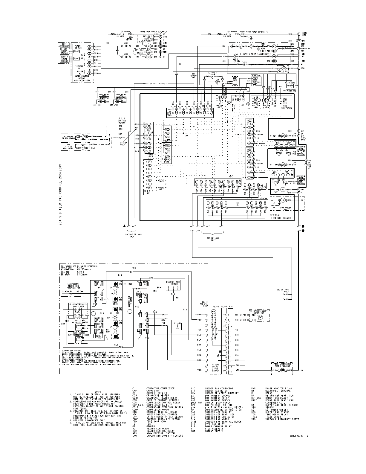
APPENDIX IV. WIRING DIAGRAMS
Fig. 58 − 50TC D30 Control Diagram − 208/230−3−60
C150370
69
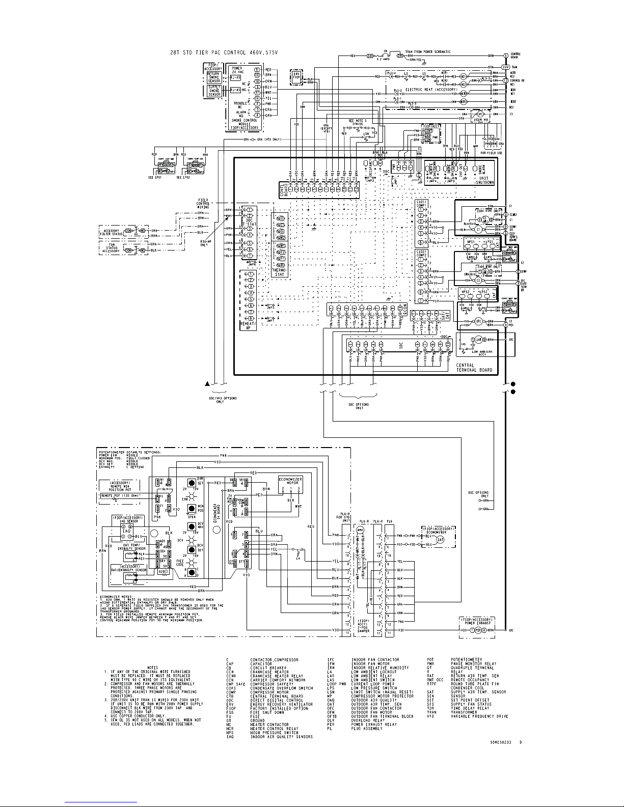
APPENDIX IV. WIRING DIAGRAMS
Fig. 59 − 50TC D30 Control Diagram − 460/575−3−60
5
C150368
70
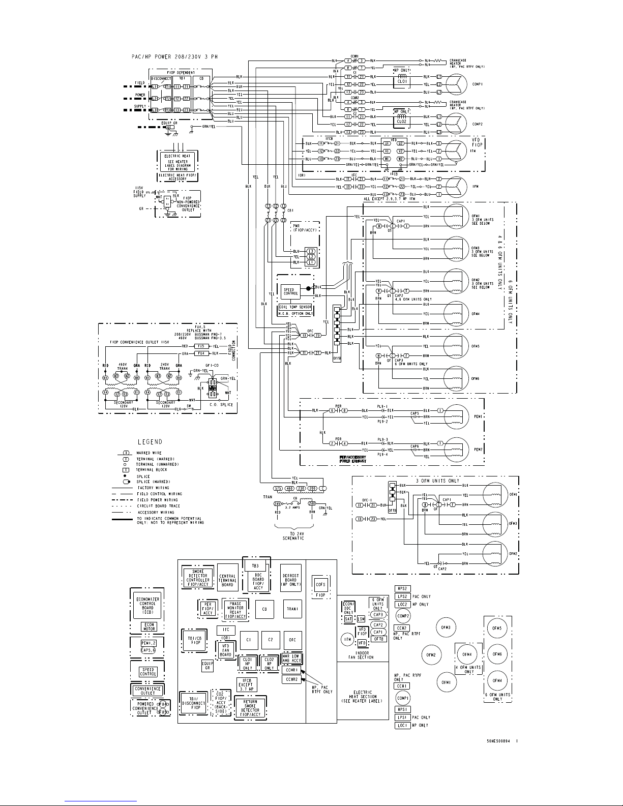
APPENDIX IV. WIRING DIAGRAMS
Fig. 60 − 50TC D17 − D30 Power Diagram − 208/230−3−60
C150373
71

APPENDIX IV. WIRING DIAGRAMS
Fig. 61 − 50TC D17 − D30 Power Diagram 460/575−3−60
C12399
72

APPENDIX IV. WIRING DIAGRAMS
Fig. 62 − 50TC D17 − D30 Control Diagram 208/230−3−60; 460/575−3−60 with Humidi−MiZer®
C150375
73

APPENDIX IV. WIRING DIAGRAMS
Fig. 63 − 50TC D17 − D30 Power Diagram 208/230−3−60 with Humidi−MiZer®
C150376
74

APPENDIX IV. WIRING DIAGRAMS
Fig. 64 − 50TC D17 − D30 Power Diagram 460−3−60 with Humidi−MiZer®
C150378
75

APPENDIX IV. WIRING DIAGRAMS
Fig. 65 − 50TC D17 − D30 Power Diagram 575−3−60 with Humidi−MiZer®
C150379
76

APPENDIX IV. WIRING DIAGRAMS
Fig. 66 − 50TC − PremierLinkt System Control Wiring Diagram
C12690
77

APPENDIX IV. WIRING DIAGRAMS
Fig. 67 − 50TC − RTU−OPEN Wiring Diagram
C12691
78

APPENDIX IV. WIRING DIAGRAMS
Fig. 68 − 50TC − SAV − VFD System Control Wiring Diagram
C12689A
79

APPENDIX V. MOTORMASTER SENSOR LOCATIONS
SENSOR
LOCATION
Fig. 69 − Motormaster Sensor Locations − D17, D20, and D24
SENSOR
LOCATION
C12258
Fig. 70 − Motormaster Sensor Location − D28
Copyright 2015 Carrier Corp. 7310 W. Morris St. Indianapolis, IN 46231 Edition Date: 12/15
Manufacturer reserves the right to change, at any time, specifications and designs without notice and without obligations.
80
C12259
Catalog No: 50TC-17-30-01SM
Replaces: 50TC-4SM

UNIT START-UP CHECKLIST
I. PRELIMINARY INFORMATION:
MODEL NO.:
DATE: ______________
SERIAL NO: _____________________________________
TECHNICIAN: ___________________________________
II. PRE-START-UP (insert check mark in box as each item is completed):
VERIFY THAT JOBSITE VOLTAGE AGREES WITH VOLTAGE LISTED ON RATING PLATE
VERIFY THAT ALL PACKAGING MATERIALS HAVE BEEN REMOVED FROM UNIT
REMOVE ALL SHIPPING HOLD DOWN BOLTS AND BRACKETS PER INSTALLATION INSTRUCTIONS
VERIFY THAT CONDENSATE CONNECTION IS INSTALLED PER INSTALLATION INSTRUCTIONS
VERIFY THAT FLUE HOOD IS INSTALLED
CHECK REFRIGERANT PIPING FOR INDICATIONS OF LEAKS; INVESTIGATE AND REPAIR IF NECESSARY
CHECK GAS PIPING FOR LEAKS
CHECK ALL ELECTRICAL CONNECTIONS AND TERMINALS FOR TIGHTNESS
CHECK THAT RETURN (INDOOR) AIR FILTERS ARE CLEAN AND IN PLACE
VERIFY THAT UNIT INSTALLATION IS LEVEL
CHECK FAN WHEEL AND PROPELLER FOR LOCATION IN HOUSING/ORIFICE AND SETSCREW TIGHTNESS
CHECK TO ENSURE THAT ELECTRICAL WIRING IS NOT IN CONTACT WITH REFRIGERANT LINES OR
SHARP METAL EDGES
VERIFY PULLEY ALIGNMENT AND BELT TENSION PER INSTALLATION INSTRUCTIONS
III. START-UP (REFER TO UNIT SERVICE/MAINTENANCE MANUAL FOR INSTRUCTIONS)
ELECTRICAL
SUPPLY VOLTAGE L1-L2 L2-L3 L3-L1
CIRCUIT 1 COMPRESSOR AMPS L1
CIRCUIT 2 COMPRESSOR AMPS L1 L2 L2
INDOOR FAN AMPS L1 L2 L2
OUTDOOR FAN AMPS NO. 1 NO. 2
L2 L2
TEMPERATURES
OUTDOOR-AIR TEMPERATURE DB WB
RETURN-AIR TEMPERATURE
COOLING SUPPLY AIR
GAS HEAT SUPPLY AIR
DB WB
DB WB
DB
PRESSURES
GAS INLET PRESSURE IN. WG
GAS MANIFOLD PRESSURE
REFRIGERANT SUCTION, CIRCUIT 1
REFRIGERANT SUCTION, CIRCUIT 2
REFRIGERANT DISCHARGE, CIRCUIT 1
IN. WG (LOW FIRE) IN. WG (HI FIRE)
PSIG F
PSIG F
PSIG F
REFRIGERANT DISCHARGE, CIRCUIT 2
VERIFY THAT 3−PHASE FAN MOTOR AND BLOWER ARE ROTATING IN CORRECT DIRECTION
VERIFY THAT 3−PHASE SCROLL COMPRESSOR IS ROTATING IN CORRECT DIRECTION
VERIFY REFRIGERANT CHARGE USING CHARGING CHARTS
GENERAL
SET ECONOMIZER MINIMUM VENT AND CHANGEOVER SETTINGS TO MATCH JOB REQUIREMENTS
(IF EQUIPPED)
PSIG F
81

Copyright 2015 Carrier Corp. 7310 W. Morris St. Indianapolis, IN 46231 Edition Date: 12/15
Manufacturer reserves the right to change, at any time, specifications and designs without notice and without obligations.
Catalog No: 50TC-17-30-01SM
Replaces: 50TC-4SM
82
 Loading...