

Page 1

Rooftop Water Source Heat Pumps
®
with PURON
Refrigerant (R-410A)
Installation, Start-Up, and
Service Instructions
AQUAZONE™
50RTP03-20
CONTENTS
Page
SAFETY CONSIDERATIONS . . . . . . . . . . . . . . . . . . .1,2
GENERAL . . . . . . . . . . . . . . . . . . . . . . . . . . . . . . . . . . . . . . . . 2
INSTALLATION . . . . . . . . . . . . . . . . . . . . . . . . . . . . . 2-34
Step 1 — Check Jobsite . . . . . . . . . . . . . . . . . . . . . . . . 2
Step 2 — Check Unit . . . . . . . . . . . . . . . . . . . . . . . . . . . 2
• STORAGE
•PROTECTION
•INSPECT UNIT
Step 3 — Locate Unit. . . . . . . . . . . . . . . . . . . . . . . . . . . . . 3
Step 4 — Mount the Unit . . . . . . . . . . . . . . . . . . . . . . . . . 8
Step 5 — Install Condensate Drain . . . . . . . . . . . . . . . 8
Step 6 — Make Piping Connections . . . . . . . . . . . . . . 8
• WATER LOOP APPLICATIONS
• GROUND-WATER APPLICATIONS
• GROUND-LOOP APPLICATIONS
Step 7 — Connect Electrical Wiring . . . . . . . . . . . . . . 9
• SUPPLY VOLTAGE
• 208-VOLT OPERATION
• BLOWER SELECTION
Step 8 — Connect Low Voltage Wiring . . . . . . . . . . 34
• THERMOSTAT CONNECTIONS
• WATER FREEZE PROTECTION
• AIR COIL FREEZE PROTECTION
• ACCESSORY CONNECTIONS
• WATER SOLENOID VALVES
PRE-START-UP . . . . . . . . . . . . . . . . . . . . . . . . . . . . . . . . . . 35
System Checkout . . . . . . . . . . . . . . . . . . . . . . . . . . . . . 35
FIELD SELECTABLE INPUTS . . . . . . . . . . . . . . . .35,36
Complete C Control Jumper Settings. . . . . . . . . . . 35
Complete C Control DIP Switches. . . . . . . . . . . . . . 35
Deluxe D Control Jumper Settings . . . . . . . . . . . . . 35
Deluxe D Control DIP Switches . . . . . . . . . . . . . . . . 35
Deluxe D Control Accessory Relay
Configurations. . . . . . . . . . . . . . . . . . . . . . . . . . . . . . 36
Water Valve (Slow Opening) . . . . . . . . . . . . . . . . . . . 36
Outside-Air Damper (OAD) . . . . . . . . . . . . . . . . . . . . 36
START-UP . . . . . . . . . . . . . . . . . . . . . . . . . . . . . . . . . . . . 36-40
Operating Limits . . . . . . . . . . . . . . . . . . . . . . . . . . . . . . . . 37
Scroll Compressor Rotation. . . . . . . . . . . . . . . . . . . . . 37
Unit Start-Up Cooling Mode . . . . . . . . . . . . . . . . . . . . . 37
Unit Start-Up Heating Mode . . . . . . . . . . . . . . . . . . . . . 37
Unit Start-Up with WHSP Open Controls . . . . . . . . 38
Flow Regulation. . . . . . . . . . . . . . . . . . . . . . . . . . . . . . . . . 39
System Claening and Flushing . . . . . . . . . . . . . . . . . . 39
Antifreeze . . . . . . . . . . . . . . . . . . . . . . . . . . . . . . . . . . . . . . . 39
Cooling Tower/Boiler Systems . . . . . . . . . . . . . . . . . . 40
Ground Coupled, Closed Loop and Plateframe
Heat Exchanger Well Systems . . . . . . . . . . . . . . . . 40
OPERATION . . . . . . . . . . . . . . . . . . . . . . . . . . . . . . . . . . 40-43
Power Up Mode . . . . . . . . . . . . . . . . . . . . . . . . . . . . . . . . . 40
Page
Units with Aquazone™ Complete C Control . . . . . 40
Units with Aquazone Deluxe D Control. . . . . . . . . . 40
Units with WSHP Open Protocol . . . . . . . . . . . . . . . . 40
SYSTEM TEST . . . . . . . . . . . . . . . . . . . . . . . . . . . . . . . 43-45
Test Mode . . . . . . . . . . . . . . . . . . . . . . . . . . . . . . . . . . . . . . . 43
Retry Mode. . . . . . . . . . . . . . . . . . . . . . . . . . . . . . . . . . . . . . 43
Aquazone Deluxe D Control LED Indicators . . . . . 45
WSHP Open Test Mode. . . . . . . . . . . . . . . . . . . . . . . . . . 45
SERVICE . . . . . . . . . . . . . . . . . . . . . . . . . . . . . . . . . . . . . .45,46
Filters . . . . . . . . . . . . . . . . . . . . . . . . . . . . . . . . . . . . . . . . . . . 45
Water Coil
Condensate Drain Pans . . . . . . . . . . . . . . . . . . . . . . . . . 45
Refrigerant System. . . . . . . . . . . . . . . . . . . . . . . . . . . . . . 45
Condensate Drain Cleaning . . . . . . . . . . . . . . . . . . . . . 45
Air Coil Cleaning . . . . . . . . . . . . . . . . . . . . . . . . . . . . . . . . 45
Condenser Cleaning . . . . . . . . . . . . . . . . . . . . . . . . . . . . 45
Checking System Charge . . . . . . . . . . . . . . . . . . . . . . . 46
Refrigerant Charging. . . . . . . . . . . . . . . . . . . . . . . . . . . . 46
Air Coil Fan Motor Removal . . . . . . . . . . . . . . . . . . . . . 46
Replacing the WSHP Open Controller’s
Battery . . . . . . . . . . . . . . . . . . . . . . . . . . . . . . . . . . . . . . . . 46
TROUBLESHOOTING . . . . . . . . . . . . . . . . . . . . . . . . 47-49
Thermistor . . . . . . . . . . . . . . . . . . . . . . . . . . . . . . . . . . . . . . 47
Control Sensors. . . . . . . . . . . . . . . . . . . . . . . . . . . . . . . . . 47
APPENDIX A — WSHP OPEN SCREEN
CONFIGURATION . . . . . . . . . . . . . . . . . . . . . . . . . . 50-55
START-UP CHECKLIST . . . . . . . . . . . . . . . . . . CL-1, CL-2
IMPORTANT: Read the entire instruction manual before
starting installation.
. . . . . . . . . . . . . . . . . . . . . . . . . . . . . . . . . . . . . . . 45
SAFETY CONSIDERATIONS
Installation and servicing of air-conditioning equipment can
be hazardous due to system pressure and electrical components. Only trained and qualified service personnel should
install, repair, or service air-conditioning equipment.
Untrained personnel can perform basic maintenance functions of cleaning coils and filters and replacing filters. All other
operations should be performed by trained service personnel.
When working on air-conditioning equipment, observe precautions in the literature, tags and labels attached to the unit, and
other safety precautions that may apply.
Improper installation, adjustment, alteration, service, maintenance, or use can cause explosion, fire, electrical shock or
other conditions which may cause personal injury or property
damage. Consult a qualified installer, service agency, or your
distributor or branch for information or assistance. The
qualified installer or agency must use factory-authorized kits or
accessories when modifying this product. Refer to the individual instructions packaged with the kits or accessories when
installing.
Manufacturer reserves the right to discontinue, or change at any time, specifications or designs without notice and without incurring obligations.
Catalog No. 04-53500070-01 Printed in U.S.A. Form 50RTP-1SI Pg 1 7-10 Replaces: New
Page 2
Follow all safety codes. Wear safety glasses and work
gloves. Use quenching cloth for brazing operations. Have fire
extinguisher available. Read these instructions thoroughly and
follow all warnings or cautions attached to the unit. Consult
local building codes and the National Electrical Code (NEC)
for special installation requirements.
Understand the signal words — DANGER, WARNING,
and CAUTION. DANGER identifies the most serious hazards
which will result in severe personal injury or death. WARNING signifies hazards that could result in personal injury or
death. CAUTION is used to identify unsafe practices, which
would result in minor personal injury or product and property
damage.
Recognize safety information. This is the safety-alert
symbol ( ). When you see this symbol on the unit and in
instructions or manuals, be alert to the potential for personal
injury.
WARNING
Electrical shock can cause personal injury and death. Shut
off all power to this equipment during installation. There
may be more than one disconnect switch. Tag all disconnect locations to alert others not to restore power until work
is completed.
CAUTION
This system uses R-410A, which has higher pressures than
R-22 and other refrigerants. No other refrigerant may be
used in this system. Suction tubing design pressure is
445 psig (3068 kPa) and liquid tubing design pressure
is 656 psig (4522 kPa). Failure to use gage set, hoses,
and recovery systems designed to handle R-410A
refrigerant may result in personal injury and equipment
damage. If unsure about equipment, consult the equipment
manufacturer.
GENERAL
This Installation and Start-Up Instructions literature is for
Aquazone™ rooftop water source heat pump systems.
Rooftop water source heat pumps (WSHP) are single-package outdoor units with electronic controls designed for yearround cooling and heating.
IMPORTANT: The installation of water source heat pump
units and all associated components, parts, and accessories
which make up the installation shall be in accordance with
the regulations of ALL authorities having jurisdiction and
MUST conform to all applicable codes. It is the responsibility of the installing contractor to determine and comply
with ALL applicable codes and regulations.
INSTALLATION
Step 1 — Check Jobsite —
maintenance instructions are provided with each unit. Before
unit start-up, read all manuals and become familiar with the
unit and its operation. Thoroughly check out the system before
operation. Complete the inspections and instructions listed
below to prepare a unit for installation. See Table 1 for unit
physical data.
Installation, operation and
CAUTION
To avoid equipment damage, do not use these units as a
source of heating or cooling during the construction process. The mechanical components and filters used in these
units quickly becomes clogged with construction dirt and
debris which may cause system damage.
Step 2 — Check Unit — Upon receipt of shipment at
the jobsite, carefully check the shipment against the bill of
lading. Make sure all units have been received. Inspect the carton or crating of each unit, and inspect each unit for damage.
Ensure the shipping company makes proper notation of any
shortages or damage on all copies of the freight bill. Concealed
damage not discovered during unloading must be reported to
the shipping company within 15 days of receipt of shipment.
NOTE: It is the responsibility of the purchaser to file all
necessary claims with the shipping company.
1. Verify unit is correct model for entering water temperature of job.
2. Be sure to provide freeze protection for piping, as required. Well water applications are especially susceptible
to freezing.
3. Be sure the installation location is isolated from sleeping
areas, private offices and other acoustically sensitive
spaces.
4. Check local codes to be sure a secondary drain pan is not
required under the unit.
5. Be sure unit is mounted at a height sufficient to provide
an adequate slope of the condensate lines. If an appropriate slope cannot be achieved, a field-supplied condensate
pump may be required.
6. Provide sufficient space for duct connection.
7. Provide adequate clearance for filter replacement and
drain pan cleaning. Do not allow piping, conduit, etc. to
block filter access.
8. Provide sufficient access to allow maintenance and
servicing of the fan and fan motor, compressor and coils.
9. Provide an unobstructed path to the unit. Space should be
sufficient to allow removal of unit if necessary.
10. Provide ready access to water valves and fittings, and
screwdriver access to unit side panels, discharge collar,
and all electrical connections.
11. Where access to side panels is limited, pre-removal of the
control box side mounting screws may be necessary for
future servicing.
STORAGE — If the equipment is not installed immediately
upon its arrival at the jobsite, it should be left in its shipping
carton and stored in a clean, dry area of the building or in a
warehouse. Units must be stored in an upright position at all
times. If unit stacking is necessary, stack 50RTP03-10 units a
maximum of 2 high. Do not stack units larger than 50RTP10.
Do not remove any equipment from its shipping package until
it is needed.
PROTECTION — Once the units are properly positioned on
the jobsite, they must be covered with either a shipping carton,
vinyl film, or an equivalent protective covering. Open ends of
pipes stored on the jobsite must be capped. This precaution is
especially important in areas where painting, plastering, or
spraying of fireproof material, etc. is not yet complete. Foreign
material that is allowed to accumulate within the units can prevent proper start-up and necessitate costly clean-up operations.
Before installing any of the system components, be sure to
examine each pipe, fitting, and valve, and remove any dirt or
foreign material found in or on these components.
2
Page 3
5. Inspect all electrical connections. Be sure connections are
CAUTION
clean and tight at the terminals.
6. Compressors are internally spring-mounted. Compressors
DO NOT store or install units in corrosive environments or
in locations subject to temperature or humidity extremes
(e.g., attics, garages, rooftops, etc.). Corrosive conditions
and high temperature or humidity can significantly reduce
performance, reliability, and service life. Always move
units in an upright position. Tilting units on their sides may
cause equipment damage.
equipped with external spring vibration isolators must
have bolts loosened and shipping clamps removed.
7. Remove any blower support cardboard from inlet of the
blower if present.
8. Locate and verify any accessory kit located in compressor
section.
9. Remove any access panel screws that may be difficult to
INSPECT UNIT — To prepare the unit for installation, complete the procedures listed below:
1. Compare the electrical data on the unit nameplate with
ordering and shipping information to verify that the
correct unit has been shipped.
2. Verify that the unit is the correct model for the entering
water temperature of the job.
3. Do not remove the packaging until the unit is ready for
installation.
4. Verify that the refrigerant tubing is free of kinks or dents,
and that it does not touch other unit components.
remove once unit is installed.
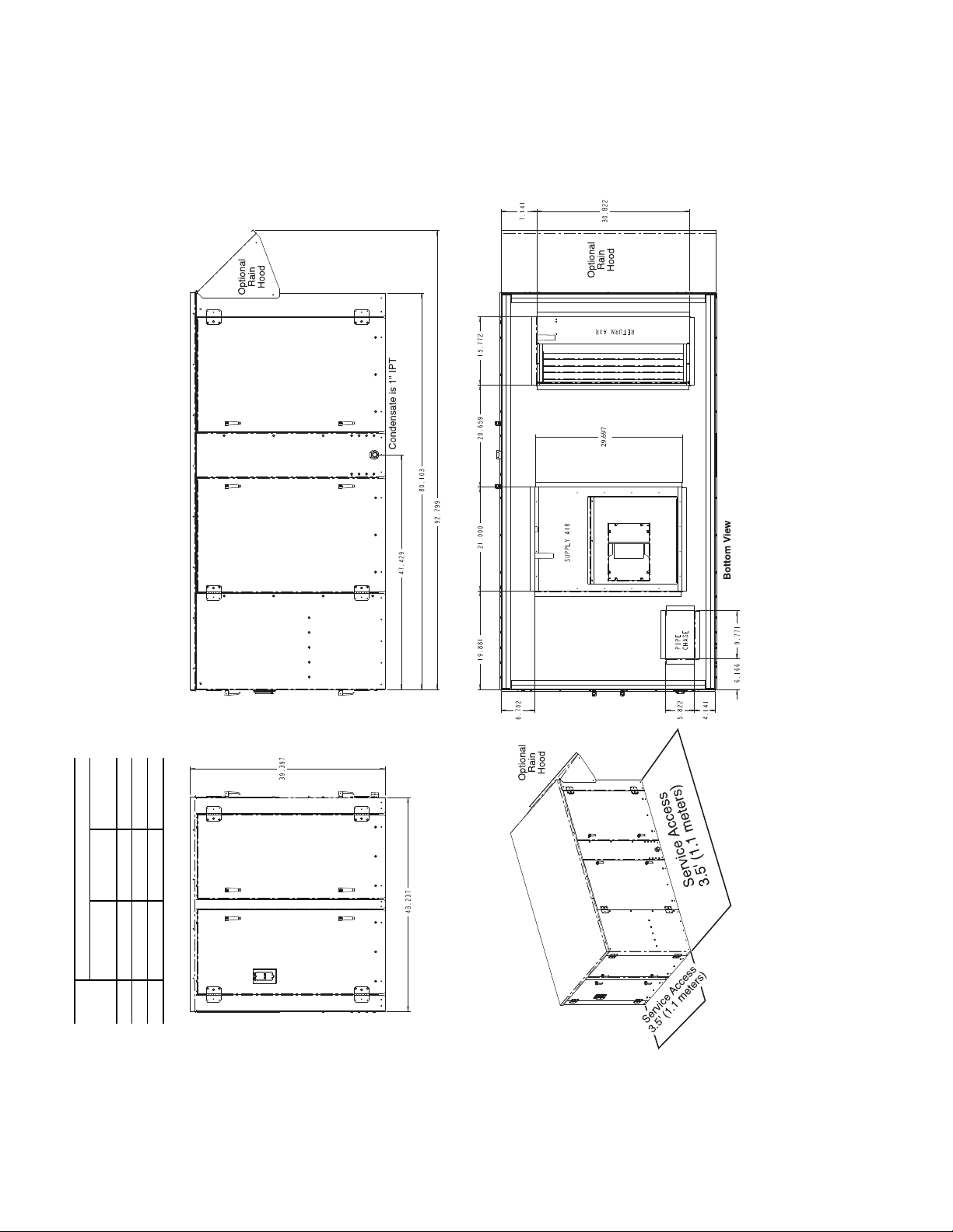
Step 3 — Locate Unit — The following guidelines
should be considered when choosing a location for WSHP. Refer to Fig. 1-3 for unit dimensional data. See Fig. 4 for accessory roof curb dimensional data.
• Provide sufficient space for water, electrical and duct
connections
• Locate unit in an area that allows for easy access and
removal of filter and access panels
• Allow enough space for service personnel to perform
maintenance
Table 1 — Physical Data — Aquazone™ 50RTP03-20 Units
UNIT 50RTP 03 04 05 06 08 10 12 14 20
Compressor (qty) Scroll (1) Scroll (2)
Factory Charge R-410A (oz) 64 84 120 132 108 120 130 192 300
Blower Motor
Motor Quantity 1
Standard Motor (hp) 1111.523335
Large Motor (hp) N/A 1.5 1.5 2 3 5 5 5 7.5
Blower(s)
Number of Blowers 12
Blower Wheel Size (dia x w) 10 x 6 2 x 12 15 x 11 15 x 15 15 x 11
V-belt size, Std drive A29 A30 A32 AX33 B40 BX42 BX46 B39 BX40
Water Connection Size
IPT (in.)
Coax Volume
Volume (US Gallons) 0.61 0.77 1.11 1.30 1.69 2.29 2.68 3.83 4.77
Condensate Connection Size
FPT (in.) 1
Air Coil Data
Air Coil Total Face Area (sq ft) 5 7 9.33 10.5 20
Filter, Standard, Qty...Size (in.) 4...16 x 20 6...16 x 20
Operating Weight (lb) 735 785 835 880 1080 1125 1175 1770 1960
Shipping Weight (lb) 750 800 850 900 1100 1150 1200 1800 2000
Corner Weights (lb)
Front-Left 184 196 208.5 224 292 303.5 320 479 530
Front-Right 259 276 293.5 298 380 395.5 406 623 690
Rear-Left 108.5 117 124.5 134 193 202 212.5 315 350
Rear-Right 183.5 196 208.5 224 215 224 236.5 353 390
Curb, Installed (lb) 83 94 128
IPT — Iron (National) Pipe Thread
3
/
4
11
1
/
4
11/
2
2
8...16 x 20,
2...20 x 20
3
Page 4
NOTES:
1. All dimensions are in inches.
2. Carrier works continuously to improve its products. As a result, the design
and specification of each product at the time of order may be changed with-
out notice.
3. Assembly tolerances ±
1
/
8
inch.
A50-8267.eps
Fig. 1 — 50RTP03-06 Unit Dimensions
50RTP
UNITS
DIMENSIONS (in.)
Outside Air
Opening Size
Wate r
In/Out (FPT)
Condensate
Drain
03,04 12.57 x 30.00
3
/
4
1
05 12.57 x 30.00 1 1
06 12.57 x 30.00 1
1
/
4
1
4
Page 5
NOTES:
1. All dimensions are in inches.
2. Carrier works continuously to improve its products. As a result, the design
and specification of each product at the time of order may be changed with-
out notice.
3. Assembly tolerances ±
1
/
8
inch.
A50-8268.eps
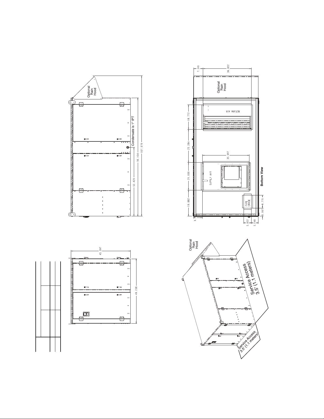
Fig. 2 — 50RTP08-12 Unit Dimensions
50RTP
UNITS
DIMENSIONS (in.)
Outside Air
Opening Size
Water
In/Out (FPT)
Condensate
Drain
08 18.95 x 36.00 1
1
/
4
1
10,12 18.95 x 36.00 1
1
/
2
1
5
Page 6
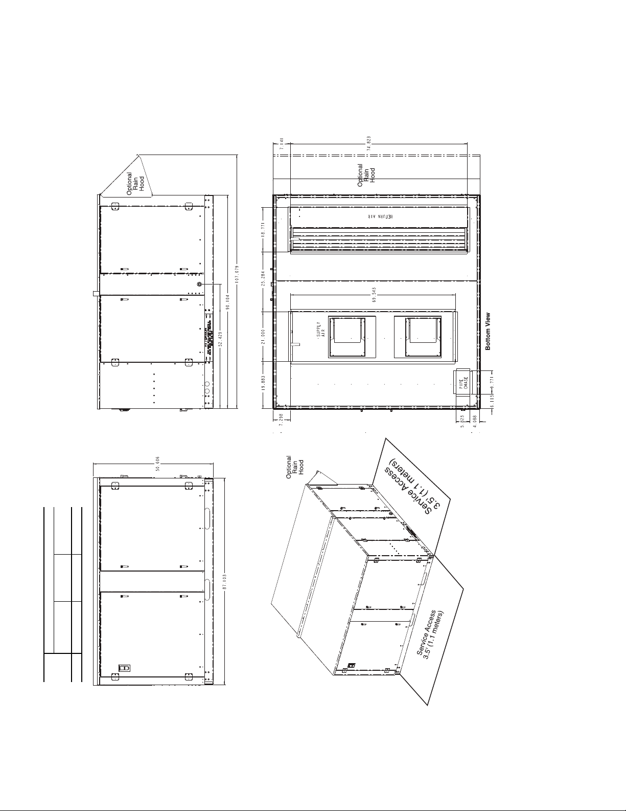
Fig. 3 — 50RTP14,20 Unit Dimensions
NOTES:
1. All dimensions are in inches.
2. Carrier works continuously to improve its products. As a result, the design
and specification of each product at the time of order may be changed with-
out notice.
3. Assembly tolerances ±
1
/
8
inch.
A50-8269.eps
50RTP
UNITS
DIMENSIONS (in.)
Outside Air
Opening Size
Water
In/Out (FPT)
Condensate
Drain
14,20 18.95 x 74.00 2 1
6
Page 7
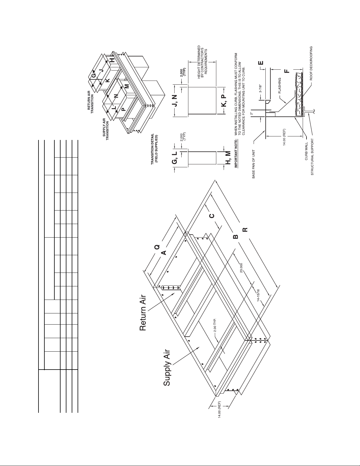
Fig. 4 — 50RTP Roof Curb Dimensions
ROOF CURB
DIMENSIONS (in.)
ABCEF
Return Air Transition Supply Air Transition
Exterior
Dimensions
GH J K LM N P Q R
50RTPACURBAAAA 35.250 72.25 18.00 1.50 12.50 22.00 16.00 39.250 33.250 27.00 21.00 39.250 33.250 39.250 76.25
50RTPACURBBAAA 41.250 82.25 21.00 1.50 12.50 25.00 19.00 45.250 39.250 27.00 21.00 45.250 39.250 45.250 86.25
50RTPACURBCAAA 78.875 82.25 21.00 5.00 9.00 25.00 19.00 82.875 76.875 27.00 21.00 82.875 76.875 82.875 86.25
7
Page 8
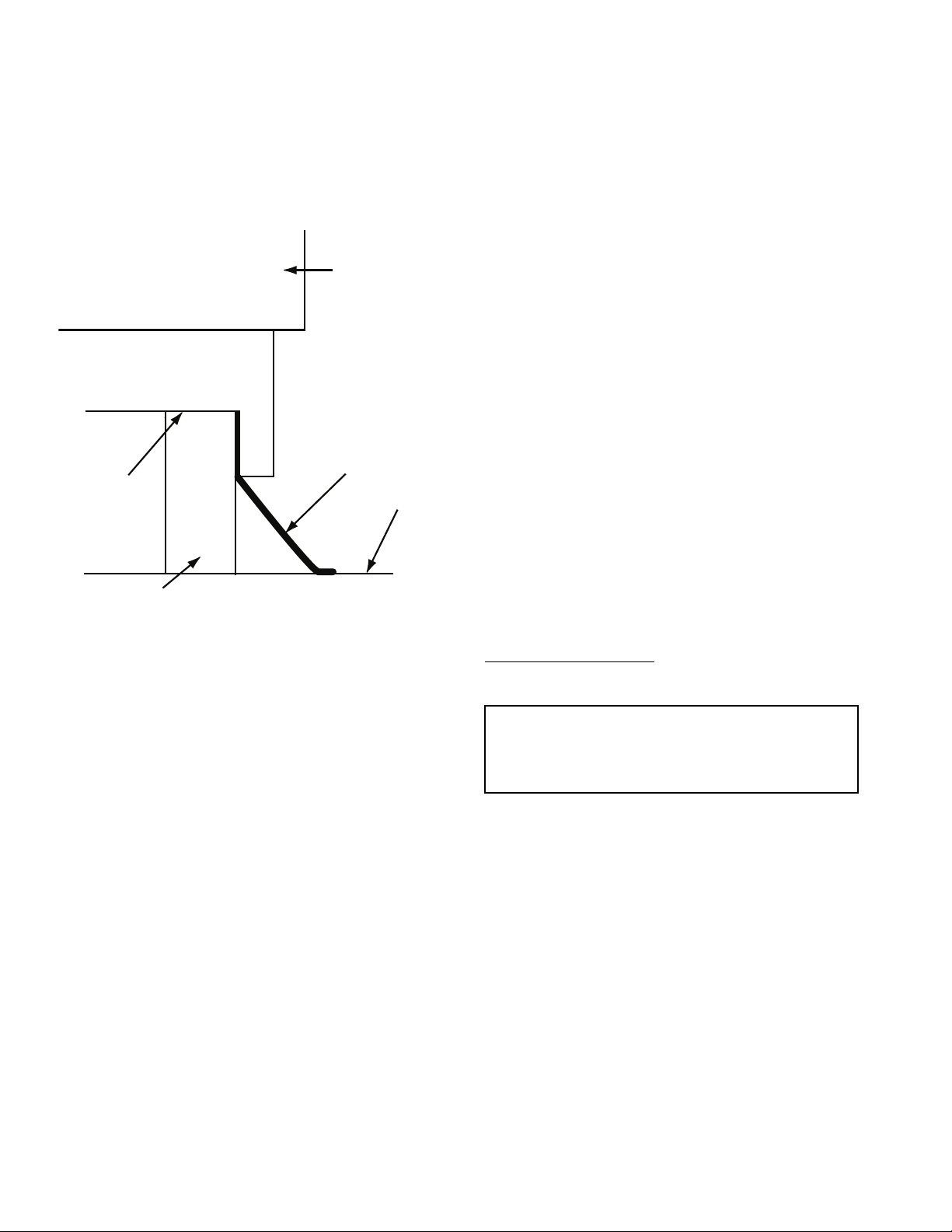
Step 4 — Mount the Unit — For proper operation,
FLASHING
ROOF
CURB
GASKET
50 RTP
UNIT
Fig. 5 — 50RTP Curb Installation
units must be mounted on a roof curb as shown in Fig. 5. Roof
curn dimensional data is shown in Fig. 4. Follow these guidelines when installing the roof curb:
1. Set unit on curb.
2. Align unit so that its return and supply air direction match
the return and supply air opening in the roof curb frame.
3. Run both the return and supply loop piping, as well as the
electrical supply line, through the pipe chase provided in
the curb.
Step 5 — Install Condensate Drain
1. Install a condensate trap at each unit with the top of
the trap positioned below the unit condensate drain
connection.
2. Design the length of the trap (water seal) based on the
amount of positive or negative pressure on the drain pan.
As a rule, 1 in. of trap is required for each inch of negative pressure on the unit.
Note that condensate is allowed to drain onto the roof.
Step 6 — Make Piping Connections — Depend-
ing on the application, there are 3 types of WSHP piping systems to choose from: water loop, ground-water and ground
loop. Refer to Piping Section of Carrier System Design Manual
for additional information.
All WSHP units use low temperature soldered female pipe
thread fittings for water connections to prevent annealing and
out-of-round leak problems which are typically associated with
high temperature brazed connections. Refer to Table 1 for connection sizes. When making piping connections, consider the
following:
• Use a backup wrench when making screw connections to
unit to prevent internal damage to piping.
• Insulation may be required on piping to avoid condensa-
tion in the case where fluid in loop piping operates at
temperatures below dew point of adjacent air.
• Piping systems that contain steel pipes or fittings may
be subject to galvanic corrosion. Dielectric fittings may
be used to isolate the steel parts of the system to avoid
galvanic corrosion.
WATER LOOP APPLICATIONS — Water loop applications
usually include a number of units plumbed to a common piping system. Maintenance to any of these units can introduce air
into the piping system. Therefore, air elimination equipment
comprises a major portion of the mechanical room plumbing.
The flow rate is usually set between 2.25 and 3 gpm per ton
of cooling capacity. For proper maintenance and servicing,
pressure-temperature (P/T) ports are necessary for temperature
and flow verification.
In addition to complying with any applicable codes, consider the following for system piping:
• Piping systems utilizing water temperatures below
50 F require
1
/2-in. closed cell insulation on all piping
surfaces to eliminate condensation.
• All plastic to metal threaded fittings should be avoided
due to the potential to leak. Use a flange fitted substitute.
• Teflon tape thread sealant is recommended to minimize
internal fouling of the heat exchanger.
• Use backup wrench. Do not overtighten connections.
• Route piping to avoid service access areas to unit.
• The piping system should be flushed prior to operation to
remove dirt and foreign materials from the system.
GROUND-WATER APPLICATIONS — In addition to complying with any applicable codes, consider the following for
system piping:
• Install shut-off valves for servicing.
• Install pressure-temperature plugs to measure flow and
temperature.
• Boiler drains and other valves should be connected using
a “T” connector to allow acid flushing for the heat
exchanger.
• Do not overtighten connections.
• Route piping to avoid service access areas to unit.
• Use PVC SCH80 or copper piping material.
NOTE: PVC SCH40 should not be used due to system high
pressure and temperature extremes.
Water Supply and Quantity
— Check water supply. Water
supply should be plentiful and of good quality. See Table 2 for
water quality guidelines.
IMPORTANT: Failure to comply with the above required
water quality and quantity limitations and the closedsystem application design requirements may cause damage
to the tube-in-tube heat exchanger that is not the responsibility of the manufacturer.
In all applications, the quality of the water circulated
through the heat exchanger must fall within the ranges listed in
the Water Quality Guidelines table. Consult a local water treatment firm, independent testing facility, or local water authority
for specific recommendations to maintain water quality within
the published limits.
GROUND-LOOP APPLICATIONS — Temperatures between
25 to 110 F and a cooling capacity of 2.25 to 3 gpm of flow per
ton is recommended. In addition to complying with any applicable codes, consider the following for system piping:
• Piping materials should be limited to only polyethylene
fusion in the buried sections of the loop.
• Galvanized or steel fittings should not be used at any
time due to corrosion.
• All plastic to metal threaded fittings should be avoided
due to the potential to leak. Use a flange fitted substitute.
• Do not overtighten connections.
• Route piping to avoid service access areas to unit.
• Pressure-temperature (P/T) plugs should be used to mea-
sure flow of pressure drop.
8
Page 9
Table 2 — Water Quality Guidelines
CONDITION
Scaling Potential — Primary Measurement
Above the given limits, scaling is likely to occur. Scaling indexes should be calculated using the limits below.
pH/Calcium
Hardness Method
Index Limits for Probable Scaling Situations (Operation outside these limits is not recommended.)
Scaling indexes should be calculated at 150 F for direct use and HWG applications, and at 90 F for indirect HX use. A monitoring plan should be
implemented.
Ryznar Stability Index
Langelier Saturation Index
Iron Fouling
2+
(Ferrous)
Iron Fe
(Bacterial Iron Potential)
Iron Fouling
Corrosion Prevention††
pH
Hydrogen Sulfide (H
Ammonia Ion as Hydroxide,
Chloride, Nitrate and Sulfate
Compounds
Maximum Chloride Levels Maximum allowable at maximum water temperature.
Erosion and Clogging
Particulate Size and Erosion
HWG — Hot Water Generator
HX — Heat Exchanger
N/A — Design Limits Not Applicable Considering Recirculating
NR — Application Not Recommended
SS — Stainless Steel
*Heat exchanger materials considered are copper, cupronickel, 304 SS (stainless
†Closed recirculating system is identified by a closed pressurized piping system.
**Recirculating open wells should observe the open recirculating design
Potable Water
steel), 316 SS, titanium.
considerations.
2
S)
LEGEND
HX
MATERIAL*
All N/A pH < 7.5 and Ca Hardness, <100 ppm
All N/A
All N/A
All N/A
All N/A
All
All N/A
All N/A
Copper N/A
CuproNickel N/A <150 ppm NR NR
304 SS N/A <400 ppm <250 ppm <150 ppm
316 SS N/A <1000 ppm <550 ppm <375 ppm
Titanium N/A >1000 ppm >550 ppm >375 ppm
All
CLOSED RECIRCULATING† OPEN LOOP AND RECIRCULATING WELL**
6.0 - 7.5
–0.5 to +0.5
<0.2 ppm (Ferrous)
<0.5 ppm of Oxygen
6 - 8.5
<0.5 ppm
<0.5 ppm
6 - 8.5
Monitor/treat as needed.
<10 ppm of particles and a max-
imum velocity of 6 fps. Filtered
for maximum
800 micron size.
If >7.5 minimize steel pipe use.
Based upon 150 F HWG and direct well, 85 F indirect well HX.
2+
If Fe
(ferrous) >0.2 ppm with pH 6 - 8, O2<5 ppm check for iron bacteria.
Minimize steel pipe below 7 and no open tanks with pH <8.
At H
S>0.2 ppm, avoid use of copper and cupronickel piping or HXs.
2
Copper alloy (bronze or brass) cast components are okay to <0.5 ppm.
50 F (10 C) 75 F (24 C) 100 F (38 C)
<20 ppm NR NR
<10 ppm (<1 ppm “sand free” for reinjection) of particles and a maximum velocity of 6
fps. Filtered for maximum 800 micron size. Any particulate that is not removed can
potentially clog components.
††If the concentration of these corrosives exceeds the maximum allowable level,
then the potential for serious corrosion problems exists.
Sulfides in the water quickly oxidize when exposed to air, requiring that no agitation occur as the sample is taken. Unless tested immediately at the site, the sample will require stabilization with a few drops of one Molar zinc acetate solution,
allowing accurate sulfide determination up to 24 hours after sampling. A low pH
and high alkalinity cause system problems, even when both values are within
ranges shown. The term pH refers to the acidity, basicity, or neutrality of the water
supply. Below 7.0, the water is considered to be acidic. Above 7.0, water is con-
sidered to be basic. Neutral water contains a pH of 7.0.
NOTE: To convert ppm to grains per gallon, divide by 17. Hardness in mg/l is equivalent to ppm.
If <–0.5 minimize steel pipe use.
Above this level deposition will occur.
Rotten egg smell appears at 0.5 ppm level.
Step 7 — Connect Electrical Wiring
WARNING
Electrical shock can cause personal injury and death. Shut
off all power to this equipment during installation. There
may be more than one disconnect switch. Tag all disconnect locations to alert others not to restore power until work
is completed.
CAUTION
Use only copper conductors for field-installed electrical
wiring. Unit terminals are not designed to accept other
types of conductors.
All field installed wiring, including the electrical ground,
MUST comply with the National Electrical Code (NEC) as
well as applicable local codes. In addition, all field wiring must
conform to the Class II temperature limitations described in the
NEC.
Refer to unit wiring diagrams in Fig. 6-16 for a schematic of
the field connections which must be made by the installing (or
electrical) contractor.
Consult the unit wiring diagram located on the inside of the
compressor access panel to ensure proper electrical hookup.
The installing (or electrical) contractor must make the field
connections when using field-supplied disconnect.
Operating voltage must be the same voltage and phase as
shown in electrical data shown in Table 3.
Make all final electrical connections with a length of flexible conduit to minimize vibration and sound transmission to
the building.
SUPPLY VOLTAGE — Operating voltage to unit must be
within voltage range indicated on unit nameplate.
On 3-phase units, voltages under load between phases must
be balanced within 2%. Use the following formula to determine the percentage voltage imbalance:
% Voltage Imbalance
= 100 x
max voltage deviation from average voltage
average voltage
9
Page 10
Example: Supply voltage is 460-3-60.
AB = 452 volts
BC = 464 volts
AC = 455 volts
Average Voltage =
452 + 464 + 455
1371
=
3
3
= 457
Determine maximum deviation from average voltage:
(AB) 457 – 452 = 5 v
(BC) 464 – 457 = 7 v
(AC) 457 – 455 = 2 v
Maximum deviation is 7 v.
Determine percent voltage imbalance.
% Voltage Imbalance = 100 x
7
457
= 1.53%
This amount of phase imbalance is satisfactory as it is
below the maximum allowable 2%.
Operation on improper line voltage or excessive phase
imbalance constitutes abuse and may cause damage to electrical components.
NOTE: If more than 2% voltage imbalance is present, contact
local electric utility.
208-VOLT OPERATION — All 208-230 volt units are factory
wired for 208 volts. The transformers may be switched to
230-volt operation (as illustrated on the wiring diagram) by
switching the red (208 volt) wire with the orange (230 volt)
wire at the L1 terminal.
BLOWER SELECTION — All water source heat pumps are
factory set with the appropriate motor and sheave combination
to achieve the desired airflow performance. Performance is
selected by matching the desired performance with the appropriate region in Tables 4-12.
NOTE: Factory-installed sheaves are field adjustable. Refer to
Tables 4-12 for adjustment points.
Table 3 — Electrical Data
50RTP
UNIT SIZE
03
04
05
06
08
10
12
VOLTAGE
CODE
5 208-3-60 197/254 A,B,C 1 10.4 73.0 1 4.0 1.0 14.4 17.0 25
6 460-3-60 414/506 A,B,C 1 5.8 38.0 1 2.0 1.0 7.8 9.3 15
1 575-3-60 518/633 A,B,C 1 3.8 36.5 1 1.4 1.0 5.2 6.2 15
5 208-3-60 197/254
6 460-3-60 414/506
1 575-3-60 518/633
5 208-3-60 197/254
6 460-3-60 414/506
1 575-3-60 518/633
5 208-3-60 197/254
6 460-3-60 414/506
1 575-3-60 518/633
5 208-3-60 197/254
6 460-3-60 414/506
1 575-3-60 518/633
5 208-3-60 197/254
6 460-3-60 414/506
1 575-3-60 518/633
5 208-3-60 197/254
6 460-3-60 414/506
1 575-3-60 518/633
VOLTAGE
(V-Ph-Hz)
MIN/MAX
VOLTAGE
BLOWER
OPTION
A,B,C 1 13.7 83.1 1 4.0 1.0 17.7 21.1 35
D,E 1 13.7 83.1 1 5.0 1.5 18.7 22.1 35
A,B,C 1 6.2 41.0 1 2.0 1.0 8.2 9.8 15
D,E 1 6.2 41.0 1 2.4 1.5 8.6 10.1 15
A,B,C 1 4.8 33.0 1 1.4 1.0 6.2 7.4 15
D,E 1 4.8 33.0 1 1.9 1.5 6.7 7.9 15
A,B,C 1 15.6 110.0 1 4.0 1.0 19.6 23.5 40
D,E 1 15.6 110.0 1 5.0 1.5 20.6 24.5 40
A,B,C 1 7.8 52.0 1 2.0 1.0 9.8 11.8 15
D,E 1 7.8 52.0 1 2.4 1.5 10.2 12.2 15
A,B,C 1 5.8 38.9 1 1.4 1.0 7.2 8.7 15
D,E 1 5.8 38.9 1 1.9 1.5 7.7 9.2 15
A,B,C 1 20.5 155.0 1 5.0 1.5 25.5 30.6 50
E 1 20.5 155.0 1 6.2 2.0 26.7 31.8 50
A,B,C 1 9.6 75.0 1 2.4 1.5 12.0 14.4 20
E 1 9.6 75.0 1 3.1 2.0 12.7 15.1 20
A,B,C 1 7.6 54.0 1 1.9 1.5 9.5 11.4 15
E 1 7.6 54.0 1 2.3 2.0 9.9 11.8 15
A,B,C 2 13.7 83.1 1 6.2 2.0 33.6 37.0 50
E 2 13.7 83.1 1 9.2 3.0 36.6 40.0 50
A,B,C 2 6.2 41.0 1 3.1 2.0 15.5 17.0 20
E 2 6.2 41.0 1 4.3 3.0 16.7 18.3 20
A,B,C 2 4.8 33.0 1 2.3 2.0 11.9 13.1 15
E 2 4.8 33.0 1 3.4 3.0 13.0 14.2 15
A,B,C 2 15.6 110.0 1 9.2 3.0 40.4 44.3 60
E 2 15.6 110.0 1 14.1 5.0 45.3 49.2 60
A,B,C 2 7.8 52.0 1 4.3 3.0 19.9 21.9 25
E 2 7.8 52.0 1 7.0 5.0 22.6 24.6 30
A,B,C 2 5.8 38.9 1 3.4 3.0 15.0 16.5 20
E 2 5.8 38.9 1 5.2 5.0 16.8 18.3 20
A,B,C 2 20.5 155.0 1 9.2 3.0 50.2 55.3 80
D,E 2 20.5 155.0 1 14.1 5.0 55.1 60.2 80
A,B,C 2 9.6 75.0 1 4.3 3.0 23.5 25.9 35
D,E 2 9.6 75.0 1 7.0 5.0 26.2 28.6 35
A,B,C 2 7.6 54.0 1 3.4 3.0 18.6 20.5 25
D,E 2 7.6 54.0 1 5.2 5.0 20.4 22.3 25
COMPRESSOR MOTOR TOTAL
Qty RLA LRA Qty FLA Hp
UNIT
FLA
MCA
MAX
FUSE/
HACR
10
Page 11
Table 3 — Electrical Data (cont)
50RTP
UNIT SIZE
14
20
FLA — Full Load Amps
HACR — Heating, Air Conditioning, and Refrigeration
LRA — Locked Rotor Amps
MCA — Minimum Circuit Amps
RLA — Rated Load Amps
VOLTAGE
CODE
5 208-3-60 197/254
6 460-3-60 414/506
1 575-3-60 518/633
5 208-3-60 197/254
6 460-3-60 414/506
1 575-3-60 518/633
LEGEND
VOLTAGE
(V-Ph-Hz)
MIN/MAX
VOLTAGE
BLOWER
OPTION
A,B,C 2 23.2 164.0 1 9.2 3.0 55.6 61.4 80
D,E 2 23.2 164.0 1 14.1 5.0 60.5 66.3 80
A,B,C 2 11.2 75.0 1 4.3 3.0 26.7 29.5 40
D,E 2 11.2 75.0 1 7.0 5.0 29.4 32.2 40
A,B,C 2 7.9 54.0 1 3.4 3.0 19.2 21.2 30
D,E 2 7.9 54.0 1 5.2 5.0 21.0 23.0 30
A,B,C 2 30.1 225.0 1 14.1 5.0 74.3 81.8 110
D,E 2 30.1 225.0 1 21.7 7.5 81.9 89.4 110
A,B,C 2 16.7 114.0 1 7.0 5.0 40.4 44.6 60
D,E 2 16.7 114.0 1 10.0 7.5 43.4 47.6 60
A,B,C 2 12.2 80.0 1 5.2 5.0 29.6 32.6 45
D,E 2 12.2 80.0 1 7.7 7.5 32.1 35.1 45
Table 4 — 50RTP03 Blower Performance Data
AIRFLOW
(cfm)
900
1000
1100
1200
1300
1400
1500
bhp — Brake Horsepower
ESP — External Static Pressure
NOTES:
1. A = Standard RPM/Standard Motor, B = Low RPM/Standard
Motor, C = High RPM/Standard Motor
ESP
bhp 0.10 0.13 0.16 0.17 0.19 0.22 0.24 0.26 0.28 0.30 0.33 0.35 0.37 0.40 0.44 0.47
Sheave/MotorBBBAAAAAAACCCCCC
rpm 552 615 665 715 765 820 875 925 965 1010 1055 1100 1140 1180 1220 1260
Turns Open 4.5 3.5 3.0 4.5 4.0 3.5 2.5 2.0 1.5 1.0 3.0 2.5 2.0 2.0 1.5 1.0
bhp 0.16 0.17 0.19 0.21 0.23 0.25 0.28 0.30 0.33 0.36 0.40 0.43 0.46 0.49 0.52 0.55
Sheave/MotorBBAAAAAAAACCCCCC
rpm 615 655 695 740 790 845 900 940 985 1030 1070 1115 1150 1190 1230 1265
Turns Open 3.5 3.0 5.0 4.0 3.5 3.0 2.0 1.5 1.0 0.5 3.0 2.5 2.0 1.5 1.5 1.0
bhp 0.22 0.23 0.25 0.29 0.32 0.34 0.35 0.36 0.38 0.41 0.44 0.48 0.50 0.53 0.56 0.59
Sheave/MotorBAAAAAAAACCCCCCC
rpm 685 725 765 810 855 895 940 985 1025 1065 1105 1145 1180 1215 1250 1285
Turns Open 2.5 5.0 4.0 3.5 2.5 2.5 1.5 1.0 0.5 3.0 2.5 2.0 1.5 1.5 1.0 0.5
bhp 0.26 0.27 0.30 0.33 0.36 0.39 0.42 0.44 0.48 0.51 0.54 0.57 0.60 0.62 0.65 0.69
Sheave/MotorAAAAAAAACCCCCCCC
rpm 710 740 785 830 880 920 965 1005 1045 1085 1125 1160 1195 1230 1265 1300
Turns Open 5.0 4.5 3.5 3.0 2.5 2.0 1.0 0.5 3.5 3.0 2.5 2.0 1.5 1.0 1.0 0.5
bhp 0.30 0.33 0.36 0.40 0.42 0.44 0.46 0.50 0.55 0.61 0.65 0.68 0.71 0.74 0.76 0.79
Sheave/MotorAAAAAAAACCCCCCCC
rpm 750 790 830 870 910 950 990 1030 1065 1105 1140 1175 1210 1245 1280 1315
Turns Open 4.0 3.5 3.0 2.5 2.0 1.5 1.0 0.5 3.0 2.5 2.0 1.5 1.5 1.0 0.5 0.0
bhp 0.40 0.42 0.44 0.47 0.50 0.53 0.56 0.60 0.64 0.67 0.70 0.72 0.75 0.79 0.84 0.88
Sheave/MotorAAAAAAACCCCCCCCC
rpm 820 850 875 915 950 990 1025 1065 1100 1135 1170 1205 1235 1270 1305 1335
Turns Open 3.0 2.5 2.5 2.0 1.5 1.0 0.5 3.0 2.5 2.0 2.0 1.5 1.0 0.5 0.5 0.0
bhp 0.45 0.47 0.50 0.52 0.55 0.59 0.64 0.69 0.74 0.77 0.80 0.83 0.86 0.90 0.93 —
Sheave/MotorAAAAAACCCCCCCCC—
rpm 860 885 920 955 985 1020 1055 1090 1125 1160 1190 1225 1255 1290 1320 —
Turns Open 2.5 2.0 2.0 1.5 1.0 0.5 3.0 2.5 2.0 2.0 1.5 1.0 1.0 0.5 0.0 —
LEGEND
0.0 0.1 0.2 0.3 0.4 0.5 0.6 0.7 0.8 0.9 1.0 1.1 1.2 1.3 1.4 1.5
AIRFLOW (cfm) AT EXTERNAL STATIC PRESSURE (in. wg)
COMPRESSOR MOTOR TOTAL
Qty RLA LRA Qty FLA Hp
2. Unit shipped with standard drive package with drive sheave 2.5
turns open unless otherwise requested. Field adjustment may
be required for specified CFM.
3. ISO/AHRI rating point with standard drive package and drive
sheave open 3.0 turns at .30 ESP.
4. Performance data does not include drive losses and is based
on sea level conditions.
5. All airflow is rated at lowest voltage if unit is dual rated, i.e.,
rated at 208 volts for 208-230 volt units.
UNIT
FLA
MCA
MAX
FUSE/
HACR
11
Page 12

Table 5 — 50RTP04 Blower Performance Data
AIRFLOW
(cfm)
1200
1300
1400
1500
1600
1700
1800
1900
2000
bhp — Brake Horsepower
ESP — External Static Pressure
NOTES:
1. A = Standard RPM/Standard Motor, B = Low RPM/Standard
Motor, C = High RPM/Standard Motor, D = Standard RPM/
Large Motor, E = High RPM/Large Motor
ESP
bhp 0.27 0.31 0.34 0.37 0.40 0.42 0.45 0.48 0.52 0.55 0.58 0.60 0.63 0.66 0.70 0.73
Sheave/MotorBBAAAAAAAAACCCCC
rpm 750 800 845 890 935 975 1015 1055 1095 1135 1170 1205 1240 1275 1310 1345
Turns Open 5.0 4.0 5.0 4.0 3.5 3.0 2.5 1.5 1.0 0.5 0.0 3.0 2.5 2.0 1.5 1.5
bhp 0.35 0.38 0.41 0.43 0.45 0.47 0.53 0.59 0.64 0.67 0.70 0.72 0.75 0.78 0.80 0.83
Sheave/MotorBAAAAAAAAACCCCCC
rpm 810 850 890 930 970 1010 1050 1090 1125 1160 1195 1230 1265 1300 1330 1365
Turns Open 4.0 4.5 4.0 3.5 3.0 2.5 2.0 1.0 0.5 0.0 3.0 3.0 2.5 2.0 1.5 1.0
bhp 0.43 0.46 0.49 0.52 0.55 0.58 0.62 0.66 0.68 0.71 0.74 0.77 0.82 0.86 0.91 0.96
Sheave/MotorAAAAAAAAACCCCCCC
rpm 865 900 935 970 1010 1045 1085 1120 1155 1190 1220 1255 1290 1320 1355 1390
Turns Open 4.5 4.0 3.5 3.0 2.5 2.0 1.5 0.5 0.0 3.5 3.0 2.5 2.0 1.5 1.0 1.0
bhp 0.49 0.52 0.54 0.57 0.62 0.68 0.73 0.76 0.79 0.82 0.85 0.89 0.92 0.96 1.00 1.05
Sheave/MotorAAAAAAAACCCCCCEE
rpm 910 945 975 1010 1045 1080 1115 1150 1180 1215 1250 1280 1310 1345 1375 1405
Turns Open 3.5 3.5 3.0 2.5 2.0 1.5 1.0 0.0 3.5 3.0 2.5 2.0 2.0 1.5 1.0 0.5
bhp 0.62 0.65 0.67 0.70 0.72 0.75 0.78 0.82 0.86 0.89 0.94 1.00 1.04 1.08 1.13 1.18
Sheave/MotorAAAAAAACCCCEEEEE
rpm 960 985 1015 1050 1080 1115 1145 1175 1210 1240 1275 1305 1335 1365 1395 1425
Turns Open 3.0 2.5 2.5 2.0 2.0 1.5 0.5 3.5 3.0 2.5 2.5 2.0 1.5 1.0 0.5 0.5
bhp 0.74 0.77 0.80 0.83 0.85 0.88 0.90 0.93 0.95 1.00 1.06 1.11 1.17 1.22 1.27 1.31
Sheave/MotorAAAAAACCCEEEEEEE
rpm 1000 1030 1060 1090 1115 1150 1180 1210 1240 1270 1300 1330 1360 1390 1420 1445
Turns Open 2.5 2.0 1.5 1.5 1.0 1.0 3.5 3.0 3.0 2.5 2.0 1.5 1.0 1.0 0.5 0.0
bhp 0.83 0.87 0.90 0.94 0.98 1.02 1.06 1.09 1.14 1.18 1.23 1.28 1.32 1.36 — —
Sheave/MotorAAAAAEEEEEEEEE——
rpm 1050 1075 1100 1125 1155 1185 1215 1245 1275 1300 1330 1360 1385 1415 — —
Turns Open 2.0 1.5 1.0 0.5 0.5 3.5 3.0 2.5 2.5 2.0 1.5 1.0 1.0 0.5 — —
bhp 0.971.001.031.081.121.161.201.251.291.341.381.42————
Sheave/MotorADDEEEEEEEEE————
rpm 1100 1120 1145 1175 1200 1225 1250 1280 1305 1335 1360 1385 ————
Turns Open1.01.00.53.53.03.02.52.02.01.51.01.0————
bhp 1.131.171.201.241.281.321.361.401.44———————
Sheave/MotorDDEEEEEEE———————
rpm 1145 1170 1190 1215 1235 1260 1290 1315 1340 — — — ————
Turns Open0.50.53.03.02.52.52.01.51.5———————
LEGEND
0.0 0.1 0.2 0.3 0.4 0.5 0.6 0.7 0.8 0.9 1.0 1.1 1.2 1.3 1.4 1.5
AIRFLOW (cfm) AT EXTERNAL STATIC PRESSURE (in. wg)
2. Unit shipped with standard drive package with drive sheave 2.5
turns open unless otherwise requested. Field adjustment may
be required for specified CFM.
3. ISO/AHRI rating point with standard drive package and drive
sheave open 3.0 turns at .30 ESP.
4. Performance data does not include drive losses and is based
on sea level conditions.
5. All airflow is rated at lowest voltage if unit is dual rated, i.e.,
rated at 208 volts for 208-230 volt units.
12
Page 13

Table 6 — 50RTP05 Blower Performance Data
AIRFLOW
(cfm)
1500
1600
1700
1800
1900
2000
2100
2200
2300
2400
2500
bhp — Brake Horsepower
ESP — External Static Pressure
NOTES:
1. A = Standard RPM/Standard Motor, B = Low RPM/Standard
Motor, C = High RPM/Standard Motor, D = Standard RPM/
Large Motor, E = High RPM/Large Motor
ESP
bhp 0.17 0.22 0.26 0.29 0.31 0.34 0.37 0.40 0.44 0.47 0.5 0.53 0.56 0.60 0.63 0.65
Sheave/MotorBBBBAAAAAAAAACCC
rpm 516 573 625 670 710 755 785 820 850 880 900 925 945 970 990 1010
Turns Open 5.0 4.5 3.5 2.5 4.5 4.0 3.5 3.0 2.0 1.5 1.5 1.0 0.5 3.0 2.5 2.5
bhp 0.20 0.24 0.28 0.32 0.35 0.38 0.41 0.45 0.48 0.52 0.55 0.58 0.62 0.65 0.68 0.70
Sheave/MotorBBBAAAAAAAAACCCC
rpm 526 583 635 680 725 765 795 830 860 890 915 940 965 990 1010 1030
Turns Open 5.0 4.5 3.5 5.0 4.5 3.5 3.0 2.5 2.0 1.5 1.0 0.5 3.0 2.5 2.5 2.0
bhp 0.23 0.26 0.30 0.34 0.38 0.42 0.45 0.49 0.53 0.56 0.60 0.64 0.67 0.71 0.73 0.75
Sheave/MotorBBBAAAAAAAAACCCC
rpm 536 589 640 685 730 770 805 840 875 900 930 955 980 1005 1025 1045
Turns Open 4.5 4.0 3.0 5.0 4.0 3.5 3.0 2.5 2.0 1.5 1.0 0.5 3.0 2.5 2.0 2.0
bhp 0.25 0.29 0.33 0.37 0.41 0.46 0.50 0.54 0.58 0.62 0.65 0.68 0.72 0.76 0.78 0.81
Sheave/MotorBBBAAAAAAAACCCCC
rpm 547 599 650 695 740 780 815 855 885 915 940 965 995 1020 1040 1060
Turns Open 4.5 4.0 3.0 4.5 4.0 3.5 2.5 2.0 1.5 1.0 0.5 3.0 2.5 2.0 2.0 1.5
bhp 0.29 0.32 0.37 0.41 0.46 0.50 0.55 0.59 0.62 0.66 0.70 0.73 0.77 0.81 0.85 0.88
Sheave/MotorBBBAAAAAAAACCCCC
rpm 568 620 665 710 755 790 830 865 895 925 955 985 1015 1035 1060 1080
Turns Open 4.5 3.5 3.0 4.5 3.5 3.0 2.5 2.0 1.5 1.0 0.5 2.5 2.0 2.0 1.5 1.0
bhp 0.33 0.36 0.42 0.47 0.52 0.57 0.61 0.66 0.69 0.73 0.77 0.81 0.85 0.89 0.92 0.96
Sheave/MotorBBAAAAAAAACCCCCC
rpm 589 635 680 725 765 805 845 880 910 940 975 1005 1030 1055 1075 1100
Turns Open 4.0 3.5 5.0 4.0 3.5 3.0 2.0 1.5 1.0 0.5 3.0 2.5 2.0 1.5 1.5 1.0
bhp 0.41 0.45 0.49 0.52 0.57 0.63 0.68 0.72 0.76 0.80 0.84 0.88 0.92 0.96 1.00 1.04
Sheave/MotorBBAAAAAAAACCCCEE
rpm 615 660 700 740 780 820 860 895 925 960 990 1020 1045 1070 1095 1120
Turns Open 3.5 3.0 4.5 4.0 3.0 2.5 2.0 1.5 1.0 0.5 2.5 2.0 2.0 1.5 1.0 0.5
bhp 0.44 0.49 0.54 0.58 0.64 0.69 0.74 0.78 0.83 0.87 0.91 0.96 1.00 1.04 1.08 1.12
Sheave/MotorBAAAAAAAACCCEEEE
rpm 640 680 720 760 800 840 880 910 945 975 1005 1035 1060 1085 1115 1135
Turns Open 3.0 5.0 4.5 3.5 3.0 2.5 1.5 1.0 0.5 3.0 2.5 2.0 1.5 1.5 1.0 0.5
bhp 0.52 0.56 0.60 0.65 0.70 0.75 0.80 0.85 0.89 0.94 1.00 1.05 1.11 1.16 1.22 1.25
Sheave/MotorBAAAAAAACCEEEEEE
rpm 665 705 745 785 825 860 895 930 960 995 1025 1050 1080 1105 1135 1155
Turns Open 3.0 4.5 4.0 3.5 2.5 2.0 1.5 0.5 3.0 2.5 2.0 2.0 1.5 1.0 0.5 0.5
bhp 0.57 0.62 0.67 0.73 0.79 0.84 0.89 1.00 1.00 1.03 1.08 1.14 1.20 1.26 1.30 1.35
Sheave/MotorAAAAAAADDEEEEEEE
rpm 695 735 775 810 850 885 920 950 980 1015 1040 1070 1100 1130 1150 1175
Turns Open 5.0 4.0 3.5 3.0 2.0 1.5 1.0 0.5 0.0 2.0 2.0 1.5 1.0 0.5 0.5 0.0
bhp 0.64 0.69 0.75 0.81 0.87 0.92 1.00 1.01 1.05 1.11 1.17 1.23 1.29 1.34 1.39 1.43
Sheave/MotorAAAAAADDEEEEEEEE
rpm 725 765 800 835 870 905 940 970 1000 1030 1060 1090 1120 1145 1170 1190
Turns Open 4.5 3.5 3.0 2.5 2.0 1.5 0.5 0.0 2.5 2.0 1.5 1.0 0.5 0.5 0.0 0.0
LEGEND
0.0 0.1 0.2 0.3 0.4 0.5 0.6 0.7 0.8 0.9 1.0 1.1 1.2 1.3 1.4 1.5
AIRFLOW (cfm) AT EXTERNAL STATIC PRESSURE (in. wg)
2. Unit shipped with standard drive package with drive sheave 2.5
turns open unless otherwise requested. Field adjustment may
be required for specified CFM.
3. ISO/AHRI rating point with standard drive package and drive
sheave open 3.0 turns at .30 ESP.
4. Performance data does not include drive losses and is based
on sea level conditions.
5. All airflow is rated at lowest voltage if unit is dual rated, i.e.,
rated at 208 volts for 208-230 volt units.
13
Page 14

Table 7 — 50RTP06 Blower Performance Data
AIRFLOW
(cfm)
1800
1900
2000
2100
2200
2300
2400
2500
2600
2700
2800
2900
3000
ESP
bhp 0.270.310.350.390.430.470.510.550.590.620.660.700.740.760.790.83
Sheave/MotorBBBBAAAAAAAAACCC
rpm 568 620 665 710 755 790 830 865 895 920 950 975 1005 1025 1045 1070
Turns Open 5.0 3.5 2.5 1.5 5.0 4.0 3.5 3.0 2.5 2.0 1.0 0.5 0.0 4.0 4.0 3.5
bhp 0.290.330.370.420.460.500.550.590.630.670.700.740.770.810.850.89
Sheave/MotorBBBBAAAAAAAACCCC
rpm 573 625 670 715 755 795 830 870 900 930 960 990 1015 1040 1060 1085
Turns Open 4.5 3.5 2.5 1.5 5.0 4.0 3.5 3.0 2.0 1.5 1.0 0.5 4.5 4.0 3.5 3.5
bhp 0.320.360.410.460.510.560.600.650.690.720.760.800.840.880.920.96
Sheave/MotorBBBBAAAAAAAACCCC
rpm 583 630 675 720 760 800 835 875 905 935 970 1000 1025 1050 1075 1100
Turns Open 4.5 3.0 2.0 1.0 4.5 3.5 3.0 2.5 2.0 1.5 0.5 0.0 4.0 3.5 3.5 3.0
bhp 0.390.440.470.510.560.610.660.710.750.790.830.870.910.950.991.03
Sheave/MotorBBBBAAAAAAACCCCC
rpm 599 645 685 725 770 805 845 885 915 950 980 1010 1035 1060 1085 1110
Turns Open 4.0 3.0 2.0 1.0 4.5 3.5 3.0 2.5 1.5 1.0 0.5 4.5 4.0 3.5 3.0 3.0
bhp 0.420.470.520.560.620.670.720.770.810.850.890.930.981.021.061.11
Sheave/MotorBBBAAAAAAAACCCCC
rpm 620 665 705 745 785 825 865 900 930 960 995 1020 1050 1075 1100 1130
Turns Open 3.5 2.5 1.5 5.0 4.0 3.5 2.5 2.0 1.5 1.0 0.0 4.0 3.5 3.5 3.0 2.5
bhp 0.490.540.580.620.670.720.780.820.870.910.971.021.081.131.191.23
Sheave/MotorBBBAAAAAAACCCCCC
rpm 640 685 725 765 800 840 880 910 945 975 1010 1035 1065 1090 1120 1145
Turns Open 3.0 2.0 1.0 4.5 4.0 3.0 2.5 2.0 1.0 0.5 4.5 4.0 3.5 3.0 2.5 2.5
bhp 0.540.580.620.680.740.790.850.900.940.991.041.101.151.211.271.31
Sheave/MotorBBAAAAAAAACCCCCC
rpm 660 700 740 780 820 855 890 925 955 990 1020 1050 1075 1105 1135 1155
Turns Open 2.5 1.5 5.0 4.5 3.5 3.0 2.0 1.5 1.0 0.5 4.0 3.5 3.5 3.0 2.5 2.0
bhp 0.590.640.690.750.810.870.920.961.011.051.111.171.231.291.341.39
Sheave/MotorBBAAAAAAAACCCCCC
rpm 680 725 765 800 835 870 905 935 970 1000 1030 1060 1090 1120 1145 1170
Turns Open 2.0 1.0 4.5 4.0 3.5 3.0 2.0 1.5 0.5 0.0 4.0 3.5 3.0 C 2.0 2.0
bhp 0.640.690.750.800.860.920.971.021.081.131.191.251.301.361.411.50
Sheave/MotorBAAAAAAAACCCCCCE
rpm 700 740 780 815 850 885 920 950 985 1015 1045 1075 1100 1130 1155 1180
Turns Open 1.5 5.0 4.5 3.5 3.0 2.5 2.0 1.0 0.5 4.5 3.5 3.0 3.0 2.5 2.0 1.5
bhp 0.700.750.800.860.910.971.021.081.141.201.261.321.381.501.521.56
Sheave/MotorBAAAAAAACCCCCEE E
rpm 725 760 795 830 865 900 930 960 995 1025 1055 1085 1115 1140 1165 1190
Turns Open 1.0 4.5 4.0 3.5 3.0 2.0 1.5 1.0 4.5 4.0 3.5 3.0 2.5 2.0 2.0 1.5
bhp 0.760.820.880.930.981.051.101.161.221.301.371.441.501.561.631.69
Sheave/MotorAAAAAAAACCCCEE EE
rpm 745 780 815 850 880 915 945 980 1010 1040 1070 1100 1125 1150 1180 1205
Turns Open 5.0 4.0 3.5 3.0 2.5 1.5 1.0 0.5 4.5 4.0 3.5 3.0 2.5 2.0 1.5 1.5
bhp 0.820.880.930.981.051.111.171.231.301.371.441.511.591.651.711.77
Sheave/MotorAAAAAAACCCCEEEEE
rpm 765 800 830 865 900 930 960 990 1020 1050 1080 1110 1140 1165 1190 1215
Turns Open 4.5 4.0 3.5 2.5 2.0 1.5 0.5 4.5 4.0 3.5 3.0 2.5 2.5 2.0 1.5 1.0
bhp 0.910.961.021.071.131.201.261.321.381.461.531.601.661.721.781.84
Sheave/MotorAAAAAAACCCEEEEEE
rpm 785 820 855 885 915 950 980 1010 1035 1065 1095 1125 1150 1175 1200 1225
Turns Open 4.0 3.5 3.0 2.5 2.0 1.0 0.5 4.0 4.0 3.5 3.0 2.5 2.0 1.5 1.5 1.0
0.0 0.1 0.2 0.3 0.4 0.5 0.6 0.7 0.8 0.9 1.0 1.1 1.2 1.3 1.4 1.5
LEGEND
bhp — Brake Horsepower
ESP — External Static Pressure
NOTES:
1. A = Standard RPM/Standard Motor, B = Low RPM/Standard
Motor, C = High RPM/Standard Motor, E = High RPM/Large
Motor
AIRFLOW (cfm) AT EXTERNAL STATIC PRESSURE (in. wg)
2. Unit shipped with standard drive package with drive sheave 2.5
turns open unless otherwise requested. Field adjustment may
be required for specified CFM.
3. ISO/AHRI rating point with standard drive package and drive
sheave open 3.0 turns at .30 ESP.
4. Performance data does not include drive losses and is based
on sea level conditions.
5. All airflow is rated at lowest voltage if unit is dual rated, i.e.,
rated at 208 volts for 208-230 volt units.
14
Page 15

Table 8 — 50RTP08 Blower Performance Data
AIRFLOW
(cfm)
2400
2500
2600
2700
2800
2900
3000
3100
3200
3300
3400
3500
3600
3700
ESP
bhp 0.36 0.39 0.42 0.46 0.52 0.6 0.67 0.7 0.74 0.77 0.82 0.88 0.95 1.01 1.07 1.13 1.18 1.22 1.27 1.32 1.37
Sheave/MotorBBBBAAAAAAAAACCCCCCCC
rpm 500 525 563 596 632 668 704 728 756 780 808 832 856 880 904 928 948 968 988 1008 1028
Turns Open 6.0 5.0 4.0 3.0 6.0 5.0 4.5 4.0 3.5 2.5 2.0 1.5 1.0 6.0 5.5 5.0 4.5 4.5 4.0 4.0 3.5
bhp 0.40 0.45 0.50 0.56 0.62 0.67 0.72 0.76 0.80 0.85 0.90 0.97 1.05 1.12 1.18 1.22 1.26 1.31 1.36 1.40 1.46
Sheave/MotorBBBBAAAAAAAAACCCCCCCC
rpm 504 538 575 612 648 680 712 740 764 792 816 840 868 892 916 936 956 976 1000 1016 1036
Turns Open 5.5 4.5 3.5 3.0 5.5 5.0 4.5 3.5 3.0 2.5 2.0 1.5 1.0 5.5 5.0 5.0 4.5 4.0 4.0 3.5 3.5
bhp 0.47 0.51 0.55 0.60 0.67 0.73 0.78 0.84 0.89 0.94 1.00 1.05 1.11 1.16 1.23 1.28 1.35 1.41 1.46 1.51 1.56
Sheave/MotorBBBAAAAAAAAACCCCCCCCC
rpm 521 554 592 624 660 692 720 748 776 800 828 852 876 900 924 944 968 988 1008 1028 1048
Turns Open 5.5 4.5 3.5 6.0 5.5 4.5 4.0 3.5 2.5 2.0 1.5 1.0 6.0 5.5 5.0 4.5 4.0 4.0 3.5 3.5 3.0
bhp 0.51 0.56 0.61 0.66 0.72 0.77 0.82 0.88 0.94 0.99 1.06 1.14 1.21 1.27 1.32 1.39 1.44 1.50 1.55 1.59 1.65
Sheave/MotorBBBAAAAAAAAACCCCCCCCC
rpm 538 571 608 640 672 704 732 760 788 812 836 864 888 912 932 956 976 1000 1020 1036 1056
Turns Open 5.0 4.0 3.0 5.5 5.0 4.0 3.5 3.0 2.5 2.0 1.5 1.0 5.5 5.0 4.5 4.5 4.0 3.5 3.5 3.0 3.0
bhp 0.57 0.62 0.67 0.72 0.77 0.83 0.90 0.96 1.03 1.08 1.15 1.20 1.25 1.33 1.40 1.48 1.56 1.62 1.67 1.71 1.75
Sheave/MotorBBBAAAAAAAACCCCCCCCCC
rpm 550 583 616 648 684 712 740 768 796 820 848 872 896 920 940 964 988 1008 1028 1044 1064
Turns Open 4.5 3.5 2.5 5.5 5.0 4.0 3.5 3.0 2.5 2.0 1.5 6.0 5.5 5.0 4.5 4.0 4.0 3.5 3.0 3.0 2.5
bhp 0.62 0.66 0.72 0.78 0.83 0.89 0.95 1.02 1.08 1.15 1.22 1.30 1.37 1.44 1.51 1.58 1.66 1.70 1.75 1.79 1.84
Sheave/MotorBBAAAAAAAAACCCCCCCCCC
rpm 567 600 632 664 696 724 752 780 808 832 856 884 908 932 952 976 1000 1016 1036 1056 1076
Turns Open 4.0 3.0 5.5 5.0 4.5 3.5 3.0 2.5 2.0 1.5 1.0 5.5 5.0 4.5 4.5 4.0 3.5 3.5 3.0 3.0 2.5
bhp 0.68 0.73 0.78 0.83 0.89 0.97 1.05 1.13 1.18 1.24 1.30 1.35 1.42 1.51 1.60 1.68 1.76 1.80 1.85 1.88 1.92
Sheave/MotorBBAAAAAAAACCCCCCCCCCC
rpm 583 616 648 680 712 740 768 796 820 844 872 896 916 940 964 984 1008 1028 1048 1064 1084
Turns Open 3.5 2.5 5.5 5.0 4.0 3.5 3.0 2.5 1.5 1.5 6.0 5.5 5.0 4.5 4.0 4.0 3.5 3.0 3.0 2.5 2.5
bhp 0.75 0.81 0.88 0.93 1.00 1.05 1.12 1.18 1.25 1.32 1.38 1.45 1.53 1.61 1.67 1.75 1.80 1.86 1.92 2.00 2.03
Sheave/MotorBAAAAAAAAACCCCCCCCCE E
rpm 604 636 668 696 728 752 780 808 832 856 880 904 928 952 972 996 1016 1036 1056 1076 1096
Turns Open 3.0 6.0 5.0 4.5 4.0 3.0 2.5 2.0 1.5 1.0 5.5 5.0 5.0 4.5 4.0 3.5 3.5 3.0 2.5 2.5 2.0
bhp 0.80 0.86 0.93 0.99 1.07 1.15 1.23 1.28 1.34 1.39 1.44 1.52 1.61 1.69 1.78 1.86 1.91 1.96 2.01 2.06 2.12
Sheave/MotorBAAAAAAAACCCCCCCCCE EE
rpm 620 652 684 712 740 768 796 820 844 868 892 916 940 960 984 1008 1028 1048 1064 1084 1104
Turns Open 2.5 5.5 5.0 4.0 3.5 3.0 2.5 2.0 1.0 6.0 5.5 5.0 4.5 4.0 4.0 3.5 3.0 3.0 2.5 2.5 2.0
bhp 0.89 0.96 1.03 1.09 1.15 1.22 1.27 1.35 1.42 1.48 1.55 1.63 1.71 1.80 1.87 1.95 2.01 2.07 2.13 2.19 2.25
Sheave/MotorAAAAAAAAACCCCCCCE EEEE
rpm 636 668 696 724 752 780 804 832 856 880 904 924 948 972 992 1016 1036 1056 1076 1096 1112
Turns Open 6.0 5.0 4.5 4.0 3.5 2.5 2.0 1.5 1.0 5.5 5.0 5.0 4.5 4.0 3.5 3.5 3.0 2.5 2.5 2.0 2.0
bhp 0.95 1.02 1.09 1.17 1.24 1.32 1.38 1.43 1.48 1.53 1.61 1.70 1.80 1.88 2.00 2.04 2.11 2.18 2.25 2.32 2.38
Sheave/MotorAAAAA AAACCCCCCEE EEE EE
rpm 652 684 712 740 764 792 816 840 864 888 912 936 960 980 1004 1024 1044 1064 1084 1104 1120
Turns Open 5.5 4.5 4.0 3.5 3.0 2.5 2.0 1.5 6.0 5.5 5.0 4.5 4.5 4.0 3.5 3.0 3.0 2.5 2.5 2.0 1.5
bhp 1.05 1.13 1.19 1.25 1.31 1.37 1.44 1.51 1.57 1.64 1.74 1.82 1.91 2.01 2.08 2.14 2.21 2.27 2.33 2.41 2.48
Sheave/MotorAAAAA AAACCCCCEE EEE EEE
rpm 668 696 724 752 776 804 828 852 876 900 924 944 968 992 1012 1032 1052 1072 1092 1112 1128
Turns Open 5.0 4.5 4.0 3.5 3.0 2.0 1.5 1.0 5.5 5.0 5.0 4.5 4.0 3.5 3.5 3.0 3.0 2.5 2.0 2.0 1.5
bhp 1.12 1.18 1.26 1.34 1.41 1.48 1.54 1.61 1.67 1.73 1.82 1.90 1.97 2.06 2.14 2.21 2.29 2.36 2.44 2.53 2.61
Sheave/MotorAAAAA AACCCCCCEEE EEE EE
rpm 680 708 736 764 788 816 840 864 888 908 932 956 976 1000 1020 1040 1060 1080 1100 1120 1136
Turns Open 5.0 4.0 3.5 3.0 2.5 2.0 1.5 6.0 5.5 5.0 4.5 4.5 4.0 3.5 3.5 3.0 2.5 2.5 2.0 1.5 1.5
bhp 1.23 1.29 1.35 1.41 1.47 1.56 1.64 1.70 1.79 1.87 2.00 2.02 2.10 2.17 2.24 2.31 2.38 2.46 2.54 2.64 2.72
Sheave/MotorAAAAAAACCCEEEEEEEEEEE
rpm 696 724 752 776 804 828 852 872 896 920 944 964 988 1008 1028 1048 1068 1088 1108 1128 1144
Turns Open 4.5 4.0 3.5 3.0 2.0 1.5 1.0 5.5 5.0 5.0 4.5 4.5 4.0 3.5 3.0 3.0 2.5 2.5 2.0 1.5 1.5
0.00.10.20.30.40.50.60.70.80.91.01.11.21.31.41.51.61.71.81.92.0
LEGEND
bhp — Brake Horsepower
ESP — External Static Pressure
NOTES:
1. A = Standard RPM/Standard Motor, B = Low RPM/Standard
Motor, C = High RPM/Standard Motor, E = High RPM/Large
Motor
AIRFLOW (cfm) AT EXTERNAL STATIC PRESSURE (in. wg)
2. Unit shipped with standard drive package with drive sheave 2.5
turns open unless otherwise requested. Field adjustment may
be required for specified CFM.
3. ISO/AHRI rating point with standard drive package and drive
sheave open 3.0 turns at .30 ESP.
4. Performance data does not include drive losses and is based
on sea level conditions.
5. All airflow is rated at lowest voltage if unit is dual rated, i.e.,
rated at 208 volts for 208-230 volt units.
15
Page 16

Table 8 — 50RTP08 Blower Performance Data (cont)
AIRFLOW
(cfm)
3800
3900
4000
ESP
bhp 1.29 1.37 1.44 1.52 1.59 1.67 1.74 1.82 1.89 2.00 2.04 2.12 2.20 2.28 2.36 2.44 2.52 2.60 2.67 2.77 2.84
Sheave/MotorAAAAAACCCEEEEEEEEEEEE
rpm 712 740 764 792 816 840 864 888 908 932 952 976 1000 1020 1040 1060 1080 1100 1116 1136 1152
Turns Open 4.0 3.5 3.0 2.5 2.0 1.5 6.0 5.5 5.0 4.5 4.5 4.0 3.5 3.0 3.0 2.5 2.5 2.0 2.0 1.5 1.0
bhp 1.41 1.48 1.54 1.61 1.70 1.78 1.84 1.93 2.01 2.08 2.17 2.26 2.33 2.41 2.49 2.57 2.65 2.74 2.81 2.89 —
Sheave/MotorAAAAAACCEEEEEEEEEEEE—
rpm 728 752 776 804 828 852 872 896 920 940 964 988 1008 1028 1048 1068 1088 1108 1124 1144 —
Turns Open 4.0 3.0 2.5 2.0 1.5 1.0 5.5 5.5 5.0 4.5 4.0 4.0 3.5 3.0 3.0 2.5 2.0 2.0 1.5 1.0 —
bhp 1.48 1.56 1.64 1.71 1.80 1.88 2.00 2.03 2.12 2.19 2.27 2.35 2.43 2.52 2.61 2.69 2.78 2.86 2.93 — —
Sheave/MotorAAAAACEEEEEEEEEDEEE——
rpm 740 768 792 816 840 864 888 908 932 952 976 996 1016 1036 1056 1076 1096 1116 1132 — —
Turns Open 3.5 3.0 2.5 2.0 1.5 6.0 5.5 5.0 4.5 4.5 4.0 3.5 3.5 3.0 2.5 2.5 2.0 2.0 1.5 — —
0.0 0.1 0.2 0.3 0.4 0.5 0.6 0.7 0.8 0.9 1.0 1.1 1.2 1.3 1.4 1.5 1.6 1.7 1.8 1.9 2.0
LEGEND
bhp — Brake Horsepower
ESP — External Static Pressure
NOTES:
1. A = Standard RPM/Standard Motor, B = Low RPM/Standard
Motor, C = High RPM/Standard Motor, E = High RPM/Large
Motor
AIRFLOW (cfm) AT EXTERNAL STATIC PRESSURE (in. wg)
2. Unit shipped with standard drive package with drive sheave 2.5
turns open unless otherwise requested. Field adjustment may
be required for specified CFM.
3. ISO/AHRI rating point with standard drive package and drive
sheave open 3.0 turns at .30 ESP.
4. Performance data does not include drive losses and is based
on sea level conditions.
5. All airflow is rated at lowest voltage if unit is dual rated, i.e.,
rated at 208 volts for 208-230 volt units.
16
Page 17

Table 9 — 50RTP10 Blower Performance Data
AIRFLOW
(cfm)
3000
3100
3200
3300
3400
3500
3600
3700
3800
3900
4000
4100
4200
ESP
bhp 0.66 0.71 0.76 0.81 0.86 0.94 1.02 1.1 1.17 1.22 1.27 1.32 1.39 1.48 1.56 1.65 1.74 1.78 1.83 1.86 1.91
Sheave/MotorBBBBBAAAAAAAAAACCCCCC
rpm 571 604 636 668 700 728 756 784 812 836 860 884 908 932 952 976 1000 1020 1040 1056 1076
Turns Open 5.5 5.0 4.0 3.0 2.0 6.0 5.5 5.0 4.0 3.5 3.0 2.5 2.0 1.5 1.0 4.5 4.0 4.0 3.5 3.0 3.0
bhp 0.73 0.79 0.85 0.91 0.98 1.04 1.10 1.16 1.23 1.29 1.36 1.43 1.50 1.58 1.64 1.72 1.78 1.84 1.89 1.95 2.01
Sheave/MotorBBBBAAAAAAAAAACCCCCCC
rpm 592 624 656 684 716 744 772 800 824 848 872 896 920 944 964 988 1008 1028 1048 1068 1088
Turns Open 5.0 4.5 3.5 2.5 6.0 5.5 4.5 4.0 3.5 3.0 2.5 2.0 1.5 1.0 5.0 4.5 4.0 3.5 3.5 3.0 2.5
bhp 0.78 0.84 0.90 0.97 1.04 1.12 1.20 1.27 1.32 1.37 1.42 1.49 1.58 1.66 1.75 1.84 1.89 1.94 2.00 2.05 2.10
Sheave/MotorBBBBAAAAAAAAAACCCCCCC
rpm 608 640 672 704 728 756 784 812 836 860 884 908 932 952 976 1000 1020 1040 1060 1080 1100
Turns Open 4.5 4.0 3.0 2.0 5.5 5.0 4.5 4.0 3.5 3.0 2.5 2.0 1.5 1.0 4.5 4.0 4.0 3.5 3.0 3.0 2.5
bhp 0.87 0.93 1.01 1.08 1.14 1.20 1.26 1.33 1.39 1.46 1.53 1.61 1.68 1.77 1.86 1.92 1.98 2.04 2.10 2.16 2.23
Sheave/MotorBBBBAAAAAAAAACCCCCCCC
rpm 628 656 688 716 744 772 800 824 848 872 896 920 940 964 988 1008 1028 1048 1068 1088 1108
Turns Open 4.0 3.5 2.5 1.5 5.5 4.5 4.0 3.5 3.0 2.5 2.0 1.5 1.0 5.0 4.5 4.0 3.5 3.5 3.0 2.5 2.5
bhp 0.94 1.01 1.07 1.15 1.23 1.30 1.37 1.42 1.47 1.52 1.59 1.69 1.77 1.86 1.96 2.03 2.10 2.16 2.23 2.30 2.36
Sheave/MotorBBBAAAAAAAAAACCCCCCCC
rpm 644 676 704 732 760 784 812 836 860 884 908 932 952 976 1000 1020 1040 1060 1080 1100 1116
Turns Open 3.5 3.0 2.0 5.5 5.0 4.5 4.0 3.5 3.0 2.5 2.0 1.5 1.0 4.5 4.0 4.0 3.5 3.0 3.0 2.5 2.0
bhp 1.03 1.12 1.18 1.24 1.30 1.36 1.43 1.49 1.56 1.63 1.72 1.80 1.90 1.99 2.07 2.13 2.19 2.26 2.32 2.40 2.47
Sheave/MotorBBAAAAAAAAAACCCCCCCCC
rpm 660 692 720 744 772 800 824 848 872 896 920 940 964 988 1008 1028 1048 1068 1088 1108 1124
Turns Open 3.5 2.5 6.0 5.5 4.5 4.0 3.5 3.0 2.5 2.0 1.5 1.0 5.0 4.5 4.0 3.5 3.5 3.0 2.5 2.5 2.0
bhp 1.11 1.17 1.25 1.33 1.40 1.47 1.53 1.60 1.66 1.73 1.80 1.89 1.97 2.05 2.12 2.20 2.27 2.35 2.42 2.51 2.59
Sheave/MotorBBAAAAAAAAAACCCCCCCCC
rpm 676 704 732 760 784 812 836 860 884 908 928 952 976 996 1016 1036 1056 1076 1096 1116 1132
Turns Open 3.0 2.0 5.5 5.0 4.5 4.0 3.5 3.0 2.5 2.0 1.5 1.0 4.5 4.0 4.0 3.5 3.0 3.0 2.5 2.0 2.0
bhp 1.22 1.28 1.35 1.40 1.46 1.54 1.62 1.70 1.77 1.85 1.94 2.00 2.09 2.17 2.24 2.31 2.38 2.46 2.52 2.62 2.72
Sheave/MotorBAAAAAAAAAACCCCCCCCCC
rpm 692 720 748 772 800 824 848 872 892 916 940 960 984 1008 1028 1048 1068 1088 1104 1124 1144
Turns Open 2.5 6.0 5.0 4.5 4.0 3.5 3.0 2.5 2.0 1.5 1.0 5.0 4.5 4.0 3.5 3.5 3.0 2.5 2.5 2.0 1.5
bhp 1.28 1.35 1.43 1.51 1.58 1.66 1.73 1.81 1.87 1.96 2.04 2.10 2.19 2.26 2.34 2.42 2.50 2.58 2.66 2.75 2.84
Sheave/MotorBAAAAAAAAAACCCCCCCCCC
rpm 708 732 760 788 812 836 860 884 904 928 952 972 996 1016 1036 1056 1076 1096 1112 1132 1152
Turns Open 2.0 5.5 5.0 4.5 4.0 3.5 3.0 2.5 2.0 1.5 1.0 4.5 4.0 4.0 3.5 3.0 3.0 2.5 2.0 2.0 1.5
bhp 1.39 1.46 1.53 1.60 1.68 1.76 1.83 1.91 2.00 2.08 2.16 2.24 2.32 2.40 2.48 2.56 2.64 2.72 2.81 2.88 3.00
Sheave/MotorAAAAAAAAAACCCCCCCCCCE
rpm 720 748 772 800 824 848 868 892 916 940 960 984 1004 1024 1044 1064 1084 1104 1124 1140 1160
Turns Open 5.5 5.0 4.5 4.0 3.5 3.0 2.5 2.0 1.5 1.0 5.0 4.5 4.0 3.5 3.5 3.0 2.5 2.5 2.0 2.0 1.5
bhp 1.47 1.54 1.62 1.70 1.78 1.86 1.95 2.01 2.10 2.17 2.26 2.33 2.41 2.50 2.59 2.68 2.76 2.85 2.93 3.00 3.07
Sheave/MotorAAAAAAAAAACCCCCCCCCE E
rpm 736 760 788 812 836 860 884 904 928 948 972 992 1012 1032 1052 1072 1092 1112 1132 1148 1168
Turns Open 5.5 5.0 4.5 4.0 3.5 3.0 2.5 2.0 1.5 1.0 4.5 4.5 4.0 3.5 3.5 3.0 2.5 2.0 2.0 1.5 1.5
bhp 1.56 1.66 1.74 1.82 1.89 1.97 2.03 2.12 2.20 2.29 2.36 2.46 2.53 2.62 2.72 2.81 2.90 3.00 3.06 3.12 3.20
Sheave/MotorAAAAAAAAACCCCCCCCE EEE
rpm 748 776 800 824 848 872 892 916 936 960 980 1004 1020 1040 1060 1080 1100 1120 1140 1156 1176
Turns Open 5.0 4.5 4.0 3.5 3.0 2.5 2.0 1.5 1.0 5.0 4.5 4.0 4.0 3.5 3.0 3.0 2.5 2.0 2.0 1.5 1.0
bhp 1.64 1.72 1.81 1.90 1.97 2.06 2.15 2.23 2.31 2.38 2.46 2.56 2.66 2.76 2.86 3.00 3.03 3.11 3.18 3.26 3.34
Sheave/MotorAAAAAAAAACCCCCCE EEEEE
rpm 764 788 812 836 856 880 904 924 948 968 988 1012 1032 1052 1072 1088 1108 1128 1144 1164 1184
Turns Open 0.66 0.71 0.76 0.81 0.86 0.94 1.02 1.1 1.17 1.22 1.27 1.32 1.39 1.48 1.56 1.65 1.74 1.78 1.83 1.86 1.91
0.00.10.20.30.40.50.60.70.80.91.01.11.21.31.41.51.61.71.81.92.0
LEGEND
bhp — Brake Horsepower
ESP — External Static Pressure
NOTES:
1. A = Standard RPM/Standard Motor, B = Low RPM/Standard
Motor, C = High RPM/Standard Motor, E = High RPM/Large
Motor
AIRFLOW (cfm) AT EXTERNAL STATIC PRESSURE (in. wg)
2. Unit shipped with standard drive package with drive sheave 2.5
turns open unless otherwise requested. Field adjustment may
be required for specified CFM.
3. ISO/AHRI rating point with standard drive package and drive
sheave open 3.0 turns at .30 ESP.
4. Performance data does not include drive losses and is based
on sea level conditions.
5. All airflow is rated at lowest voltage if unit is dual rated, i.e.,
rated at 208 volts for 208-230 volt units.
17
Page 18

Table 9 — 50RTP10 Blower Performance Data (cont)
AIRFLOW
(cfm)
4300
4400
4500
4600
4700
4800
4900
5000
ESP
bhp 1.76 1.84 1.93 2.00 2.08 2.17 2.25 2.34 2.42 2.50 2.60 2.70 2.80 2.90 3.00 3.10 3.16 3.24 3.31 3.39 3.45
Sheave/MotorAAAAA AAACCCCCCEEEEEEE
rpm 776 800 824 844 868 892 912 936 956 976 1000 1020 1040 1060 1080 1100 1116 1136 1152 1172 1188
Turns Open 4.5 4.0 3.5 3.0 2.5 2.0 1.5 1.0 5.0 4.5 4.0 4.0 3.5 3.0 3.0 2.5 2.0 2.0 1.5 1.0 1.0
bhp 1.86 1.95 2.04 2.12 2.22 2.32 2.4 2.48 2.57 2.65 2.74 2.84 3.00 3.04 3.14 3.23 3.30 3.38 3.44 3.52 3.58
Sheave/MotorAAAAAAAACCCCEEEEEEEEE
rpm 788 812 836 856 880 904 924 944 968 988 1008 1028 1048 1068 1088 1108 1124 1144 1160 1180 1196
Turns Open 4.5 4.0 3.5 3.0 2.5 2.0 1.5 1.0 4.5 4.5 4.0 3.5 3.5 3.0 2.5 2.5 2.0 1.5 1.5 1.0 1.0
bhp 1.96 2.06 2.15 2.23 2.33 2.43 2.52 2.61 2.69 2.78 2.88 3.00 3.08 3.18 3.28 3.35 3.44 3.53 3.61 3.70 —
Sheave/MotorAAAAAAACCCCEEEEEEEEE—
rpm 800 824 848 868 892 916 936 956 976 996 1016 1036 1056 1076 1096 1112 1132 1152 1168 1188 —
Turns Open 4.0 3.5 3.0 2.5 2.0 1.5 1.0 5.0 4.5 4.0 4.0 3.5 3.0 3.0 2.5 2.0 2.0 1.5 1.5 1.0 —
bhp 2.12 2.20 2.30 2.38 2.47 2.56 2.64 2.73 2.83 2.92 3.00 3.10 3.20 3.30 3.40 3.49 3.60 3.68 3.79 3.88 —
Sheave/MotorAAAAAAACCCEEEEEEEEEE—
rpm 820 840 864 884 908 928 948 968 992 1012 1028 1048 1068 1088 1108 1124 1144 1160 1180 1196 —
Turns Open 3.5 3.0 3.0 2.5 2.0 1.5 1.0 4.5 4.5 4.0 3.5 3.5 3.0 2.5 2.5 2.0 1.5 1.5 1.0 1.0 —
bhp 2.23 2.31 2.40 2.50 2.59 2.68 2.76 2.85 3.00 3.04 3.14 3.24 3.34 3.42 3.53 3.62 3.73 3.84 3.93 — —
Sheave/MotorAAAAAACCEEEEEEEEEEE——
rpm 832 852 876 900 920 940 960 980 1000 1020 1040 1060 1080 1096 1116 1132 1152 1172 1188 — —
Turns Open 3.5 3.0 2.5 2.0 1.5 1.0 5.0 4.5 4.0 4.0 3.5 3.0 3.0 2.5 2.0 2.0 1.5 1.0 1.0 — —
bhp 2.35 2.46 2.55 2.65 2.73 2.81 2.89 3.00 3.06 3.16 3.26 3.34 3.44 3.55 3.64 3.76 3.86 3.98 4.08 — —
Sheave/MotorAAAAACCEEEEEEEEEEEE——
rpm 844 868 888 912 932 952 972 992 1012 1032 1052 1068 1088 1108 1124 1144 1160 1180 1196 — —
Turns Open 3.0 2.5 2.0 1.5 1.5 5.0 4.5 4.5 4.0 3.5 3.5 3.0 2.5 2.5 2.0 1.5 1.5 1.0 1.0 — —
bhp 2.49 2.58 2.68 2.77 2.85 3.00 3.03 3.12 3.22 3.30 3.40 3.50 3.60 3.70 3.82 3.91 4.03 4.13 — — —
Sheave/MotorAAAAAEEEEEEEEEEEEE———
rpm 860 880 904 924 944 964 984 1004 1024 1040 1060 1080 1100 1116 1136 1152 1172 1188 — — —
Turns Open 3.0 2.5 2.0 1.5 1.0 5.0 4.5 4.0 3.5 3.5 3.0 3.0 2.5 2.0 2.0 1.5 1.0 1.0 — — —
bhp 2.63 2.72 2.81 2.91 3.00 3.09 3.18 3.28 3.36 3.46 3.56 3.66 3.75 3.87 3.96 4.08 4.18 4.28 — — —
Sheave/MotorAAAAEEEEEEEEEEEEEE———
rpm 876 896 916 936 956 976 996 1016 1032 1052 1072 1092 1108 1128 1144 1164 1180 1196 — — —
Turns Open 2.5 2.0 1.5 1.0 5.0 4.5 4.0 4.0 3.5 3.5 3.0 2.5 2.5 2.0 1.5 1.5 1.0 1.0 — — —
0.0 0.1 0.2 0.3 0.4 0.5 0.6 0.7 0.8 0.9 1.0 1.1 1.2 1.3 1.4 1.5 1.6 1.7 1.8 1.9 2.0
LEGEND
bhp — Brake Horsepower
ESP — External Static Pressure
NOTES:
1. A = Standard RPM/Standard Motor, B = Low RPM/Standard
Motor, C = High RPM/Standard Motor, E = High RPM/Large
Motor
AIRFLOW (cfm) AT EXTERNAL STATIC PRESSURE (in. wg)
2. Unit shipped with standard drive package with drive sheave 2.5
turns open unless otherwise requested. Field adjustment may
be required for specified CFM.
3. ISO/AHRI rating point with standard drive package and drive
sheave open 3.0 turns at .30 ESP.
4. Performance data does not include drive losses and is based
on sea level conditions.
5. All airflow is rated at lowest voltage if unit is dual rated, i.e.,
rated at 208 volts for 208-230 volt units.
18
Page 19

Table 10 — 50RTP12 Blower Performance Data
AIRFLOW
(cfm)
3600
3800
4000
4200
4400
4600
4800
5000
5200
5400
5600
5800
6000
ESP
bhp 0.86 0.93 1.01 1.10 1.18 1.26 1.36 1.46 1.57 1.68 1.77 1.86 1.94 2.03 2.14 2.27 2.38 2.52 2.70 2.86 3.04
Sheave/MotorBBBBBAAAAAAACCCCCCCCE
rpm 640 672 704 732 760 788 816 840 868 896 924 952 980 1008 1036 1068 1096 1124 1160 1192 1228
Turns Open 5.5 5.0 4.0 3.0 2.0 6.0 5.0 4.5 3.5 3.0 2.0 1.5 6.0 5.5 5.0 4.5 4.0 3.5 3.0 2.5 2.0
bhp 1.06 1.15 1.24 1.33 1.41 1.51 1.59 1.69 1.77 1.87 1.95 2.03 2.13 2.23 2.36 2.49 2.60 2.74 2.88 3.04 3.18
Sheave/MotorBBBBAAAAAAAACCCCCCCEE
rpm 672 704 732 760 788 816 840 868 892 920 944 968 996 1020 1048 1076 1100 1128 1156 1188 1216
Turns Open 5.0 4.0 3.0 2.0 6.0 5.0 4.5 3.5 3.0 2.0 1.5 1.0 6.0 5.5 5.0 4.0 3.5 3.0 2.5 2.0 2.0
bhp 1.23 1.31 1.41 1.51 1.61 1.69 1.77 1.87 1.96 2.04 2.13 2.22 2.32 2.44 2.56 2.70 2.81 2.92 3.04 3.16 3.30
Sheave/MotorBBBAAAAAAAACCCCCCCE EE
rpm 708 732 760 788 816 840 864 892 916 940 964 988 1012 1036 1060 1088 1112 1136 1164 1192 1216
Turns Open 4.0 3.0 2.0 6.0 5.0 4.5 4.0 3.0 2.5 1.5 1.0 6.0 5.5 5.0 4.5 4.0 3.5 3.0 2.5 2.0 1.5
bhp 1.25 1.4 1.591.711.791.871.972.062.142.242.342.442.552.662.752.863.003.123.253.383.52
Sheave/MotorBBAAAAAAAACCCCCCE EEEE
rpm 696 736 784 816 840 864 892 916 936 960 984 1008 1032 1056 1076 1100 1124 1148 1172 1196 1220
Turns Open 3.5 3.0 6.0 5.0 4.5 4.0 3.0 2.5 2.0 1.0 6.0 5.5 5.0 4.5 4.0 3.5 3.0 2.5 2.0 1.5 1.5
bhp 1.56 1.69 1.79 1.88 1.96 2.04 2.14 2.24 2.35 2.45 2.54 2.65 2.74 2.85 2.96 3.07 3.20 3.34 3.45 3.59 3.74
Sheave/MotorBAAAAAAAACCCCCCE EEEEE
rpm 752 784 812 836 860 884 908 932 956 980 1000 1024 1044 1068 1092 1112 1136 1160 1180 1204 1228
Turns Open 2.5 6.0 5.0 4.5 4.0 3.0 2.5 2.0 1.0 6.0 6.0 5.5 5.0 4.5 4.0 3.5 3.0 2.5 2.0 1.5 1.0
bhp 1.77 1.88 1.96 2.05 2.13 2.22 2.33 2.42 2.53 2.62 2.75 2.85 3.00 3.11 3.22 3.32 3.44 3.54 3.64 3.78 3.92
Sheave/MotorBAAAAAAAACCCEEEEEEEEE
rpm 780 808 832 856 880 904 928 948 972 992 1016 1036 1060 1084 1104 1124 1148 1168 1188 1212 1232
Turns Open 1.5 5.5 4.5 4.0 3.5 2.5 2.0 1.5 1.0 6.0 5.5 5.0 4.5 4.0 3.5 3.0 2.5 2.0 2.0 1.5 1.0
bhp 1.98 2.08 2.17 2.27 2.37 2.48 2.57 2.67 2.76 2.89 3.00 3.11 3.22 3.33 3.44 3.55 3.68 3.79 3.9 4.04 4.18
Sheave/MotorAAAAAAAACCEEEEEEEEEEE
rpm 808 832 856 880 904 928 948 972 992 1016 1036 1056 1076 1096 1116 1136 1160 1180 1200 1220 1240
Turns Open 5.5 4.5 4.0 3.5 2.5 2.0 1.5 1.0 6.0 5.5 5.0 4.5 4.0 3.5 3.5 3.0 2.5 2.0 1.5 1.0 1.0
bhp 2.18 2.30 2.41 2.52 2.61 2.71 2.80 2.89 3.01 3.12 3.23 3.34 3.46 3.57 3.69 3.81 3.93 4.05 4.18 4.32 —
Sheave/MotorAAAAAAACEEEEEEEEEEEE—
rpm 828 856 880 904 924 948 968 988 1012 1032 1052 1072 1092 1112 1132 1152 1172 1192 1212 1232 —
Turns Open 4.54.03.52.52.01.51.06.05.55.04.54.54.03.53.02.52.01.51.51.0 —
bhp 2.41 2.50 2.60 2.72 2.82 2.94 3.04 3.17 3.29 3.44 3.58 3.70 3.82 3.92 4.01 4.13 4.23 4.33 4.47 — —
Sheave/MotorAAAAAAEEEEEEEEEEEEE——
rpm 852 876 900 924 944 968 988 1012 1032 1056 1080 1100 1120 1136 1152 1172 1188 1204 1224 — —
Turns Open 4.0 3.5 2.5 2.0 1.0 1.0 6.0 5.5 5.0 4.5 4.0 4.0 3.0 3.0 2.5 2.0 2.0 1.5 1.0 — —
bhp 2.64 2.75 2.87 3.00 3.10 3.20 3.30 3.41 3.52 3.63 3.74 3.86 4.00 4.11 4.25 4.39 4.53 4.64 4.78 — —
Sheave/MotorAAADDEEEEEEEEEEEEEE——
rpm 876 900 924 944 968 988 1008 1028 1048 1068 1088 1108 1128 1144 1164 1184 1204 1220 1240 — —
Turns Open 3.5 3.0 2.0 1.5 1.0 6.0 5.5 5.0 5.0 4.5 4.0 3.5 3.0 2.5 2.5 2.0 1.5 1.0 1.0 — —
bhp 2.88 2.98 3.10 3.20 3.32 3.42 3.54 3.66 3.78 3.90 4.03 4.14 4.28 4.42 4.53 4.67 4.78 4.92 — — —
Sheave/MotorADDDEEEEEEEEEEEEEE———
rpm 896 916 940 960 984 1004 1024 1044 1064 1084 1104 1120 1140 1160 1176 1196 1212 1232 — — —
Turns Open 3.02.51.51.06.05.55.55.04.54.03.53.03.02.52.01.51.51.0 — — —
bhp 3.12 3.25 3.36 3.47 3.60 3.72 3.84 3.96 4.08 4.18 4.31 4.45 4.56 4.70 4.84 4.96 — — — — —
Sheave/MotorDDDEEEEEEEEEEEEE—————
rpm 912 936 956 976 1000 1020 1040 1060 1080 1096 1116 1136 1152 1172 1192 1208 — — — — —
Turns Open 2.5 2.0 1.0 6.0 6.0 5.5 5.0 4.5 4.0 4.0 3.5 3.0 2.5 2.0 1.5 1.5 — — — — —
bhp 3.36 3.49 3.63 3.74 3.86 3.99 4.12 4.25 4.37 4.48 4.62 4.76 4.88 — — — — — — — —
Sheave/MotorDDDEEEEEEEEEE————————
rpm 928 952 976 996 1016 1036 1056 1076 1096 1112 1132 1152 1168 — — — — — — — —
Turns Open 2.0 1.5 1.0 6.0 5.5 5.0 4.5 4.0 3.5 3.5 3.0 2.5 2.0 — — — — — — — —
0.00.10.20.30.40.50.60.70.80.91.01.11.21.31.41.51.61.71.81.92.0
LEGEND
bhp — Brake Horsepower
ESP — External Static Pressure
NOTES:
1. A = Standard RPM/Standard Motor, B = Low RPM/Standard
Motor, C = High RPM/Standard Motor, D = Standard RPM/
Large Motor, E = High RPM/Large Motor
AIRFLOW (cfm) AT EXTERNAL STATIC PRESSURE (in. wg)
2. Unit shipped with standard drive package with drive sheave 2.5
turns open unless otherwise requested. Field adjustment may
be required for specified CFM.
3. ISO/AHRI rating point with standard drive package and drive
sheave open 3.0 turns at .30 ESP.
4. Performance data does not include drive losses and is based
on sea level conditions.
5. All airflow is rated at lowest voltage if unit is dual rated, i.e.,
rated at 208 volts for 208-230 volt units.
19
Page 20

Table 11 — 50RTP14 Blower Performance Data
AIRFLOW
(cfm)
4200
4400
4600
4800
5000
5200
5400
5600
5800
6000
6200
ESP
bhp — — — — 0.830.910.991.061.151.251.351.451.541.641.721.821.911.992.062.142.22
Sheave/Motor————BBBAAAAAAAACCCCCC
rpm — — — — 575 612 644 676 708 736 764 792 816 840 860 884 908 928 944 964 984
Turns Open — — — — 5.54.03.06.05.04.53.52.52.01.51.05.55.04.54.03.53.0
bhp — — — — 0.890.981.081.171.251.341.431.521.631.741.851.942.042.122.202.282.36
Sheave/Motor————BBBAAAAAAACCCCCCC
rpm — — — — 587 620 656 688 716 744 772 800 824 848 872 892 916 936 956 976 996
Turns Open — — — — 5.04.02.55.54.54.03.02.52.01.05.55.04.54.04.03.53.0
bhp — — — 0.86 0.95 1.06 1.16 1.28 1.36 1.43 1.50 1.60 1.73 1.85 1.98 2.10 2.18 2.26 2.34 2.42 2.50
Sheave/Motor———BBBBAAAAAAACCCCCCC
rpm — — — 558 596 632 664 700 728 752 780 808 832 856 880 904 924 944 964 984 1004
Turns Open — — — 6.04.53.52.55.04.54.03.02.01.51.05.55.04.54.03.53.02.5
bhp — — — 0.93 1.01 1.13 1.24 1.34 1.42 1.49 1.57 1.68 1.81 1.93 2.06 2.18 2.27 2.37 2.47 2.56 2.66
Sheave/Motor———BBBAAAAAAACCCCCCCC
rpm — — — 571 604 640 676 708 736 760 788 816 840 864 888 912 932 952 972 992 1012
Turns Open — — — 5.54.53.06.05.04.03.53.02.01.56.05.04.54.54.03.53.02.5
bhp — — — 1.03 1.13 1.25 1.36 1.45 1.54 1.62 1.71 1.83 1.99 2.12 2.26 2.35 2.46 2.54 2.63 2.72 2.83
Sheave/Motor———BBBAAAAAAACCCCCCCC
rpm — — — 583 616 652 688 716 744 768 796 820 848 872 896 916 940 960 980 1000 1020
Turns Open — — — 5.04.02.55.54.54.03.52.52.01.05.55.04.54.03.53.03.02.5
bhp — — 1.02 1.11 1.22 1.34 1.47 1.58 1.69 1.78 1.90 2.00 2.13 2.23 2.34 2.45 2.59 2.70 2.84 3.00 3.03
Sheave/Motor——BBBBAAAAAAACCCCCCEE
rpm — — 558 596 628 660 696 724 752 776 804 828 856 880 904 924 948 968 992 1012 1028
Turns Open — — 6.0 4.5 3.5 2.5 5.5 4.5 4.0 3.0 2.5 1.5 1.0 5.5 5.0 4.5 4.0 3.5 3.0 2.5 2.0
bhp — — 1.12 1.21 1.33 1.43 1.54 1.65 1.76 1.86 1.99 2.12 2.26 2.41 2.54 2.65 2.77 2.88 3.00 3.10 3.19
Sheave/Motor——BBBAAAAAAAACCCCCEEE
rpm — — 571 604 640 672 704 732 760 784 812 836 860 888 912 932 956 976 1000 1020 1036
Turns Open — — 5.5 4.5 3.0 6.0 5.0 4.5 3.5 3.0 2.0 1.5 1.0 5.0 4.5 4.5 4.0 3.5 3.0 2.5 2.0
bhp — — 1.23 1.33 1.43 1.54 1.66 1.79 1.91 2.04 2.17 2.27 2.38 2.50 2.63 2.79 3.00 3.09 3.24 3.32 3.41
Sheave/Motor——BBBAAAAAAACCCCEEEEE
rpm — — 583 616 648 680 712 740 764 792 820 844 868 896 916 940 964 984 1008 1024 1044
Turns Open — — 5.0 4.0 3.0 5.5 5.0 4.0 3.5 2.5 2.0 1.5 6.0 5.0 4.5 4.0 3.5 3.0 2.5 2.5 2.0
bhp — 1.221.311.421.541.651.771.892.012.122.282.412.552.712.833.003.143.273.403.473.57
Sheave/Motor—BBBBAAAAAAACCCEEEEEE
rpm — 563 596 628 660 692 720 748 776 800 828 852 876 904 924 948 972 992 1016 1032 1052
Turns Open — 5.5 4.5 3.5 2.5 5.5 4.5 4.0 3.0 2.5 1.5 1.0 5.5 5.0 4.5 4.0 3.5 3.0 2.5 2.0 1.5
bhp — 1.331.431.531.631.741.902.062.212.332.462.562.672.813.003.153.333.483.573.663.74
Sheave/Motor—BBBAAAAAAAACEEEEEEEE
rpm — 575 608 640 672 704 732 760 788 812 840 864 888 912 932 956 980 1000 1020 1040 1060
Turns Open — 5.5 4.0 3.0 6.0 5.0 4.5 3.5 3.0 2.0 1.5 1.0 5.0 4.5 4.5 4.0 3.5 3.0 2.5 2.0 1.5
bhp 1.35 1.44 1.56 1.69 1.82 1.95 2.07 2.18 2.30 2.45 2.59 2.72 2.86 3.05 3.14 3.29 3.44 3.56 3.68 3.79 3.90
Sheave/MotorBBBBAAAAAAACCEEEEEEEE
rpm 558 587 620 652 684 716 744 768 796 824 848 872 896 920 940 964 988 1008 1028 1048 1068
Turns Open 6.0 5.0 4.0 2.5 5.5 4.5 4.0 3.5 2.5 2.0 1.5 5.5 5.0 4.5 4.0 3.5 3.0 2.5 2.0 2.0 1.5
0.0 0.1 0.2 0.3 0.4 0.5 0.6 0.7 0.8 0.9 1.0 1.1 1.2 1.3 1.4 1.5 1.6 1.7 1.8 1.9 2.0
LEGEND
bhp — Brake Horsepower
ESP — External Static Pressure
NOTES:
1. A = Standard RPM/Standard Motor, B = Low RPM/Standard
Motor, C = High RPM/Standard Motor, D = Standard RPM/
Large Motor, E = High RPM/Large Motor
AIRFLOW (cfm) AT EXTERNAL STATIC PRESSURE (in. wg)
2. Unit shipped with standard drive package with drive sheave 2.5
turns open unless otherwise requested. Field adjustment may
be required for specified CFM.
3. ISO/AHRI rating point with standard drive package and drive
sheave open 3.0 turns at .30 ESP.
4. Performance data does not include drive losses and is based
on sea level conditions.
5. All airflow is rated at lowest voltage if unit is dual rated, i.e.,
rated at 208 volts for 208-230 volt units.
20
Page 21

Table 11 — 50RTP14 Blower Performance Data (cont)
AIRFLOW
(cfm)
6400
6600
6800
7000
ESP
bhp 1.43 1.54 1.66 1.78 1.90 2.05 2.21 2.37 2.52 2.62 2.73 2.83 2.95 3.13 3.28 3.47 3.65 3.76 3.87 3.97 4.08
Sheave/MotorBBBBAAAAAAACCEEEEEEEE
rpm 571 604 636 664 696 724 752 780 808 832 856 880 904 928 948 972 996 1016 1036 1056 1076
Turns Open 5.5 4.5 3.5 2.5 5.5 4.5 4.0 3.0 2.5 1.5 1.0 5.5 5.0 4.5 4.0 3.5 3.0 2.5 2.0 1.5 1.0
bhp 1.55 1.68 1.83 1.96 2.12 2.24 2.36 2.47 2.61 2.74 3.00 3.01 3.17 3.34 3.48 3.66 3.82 3.94 4.06 4.16 4.28
Sheave/MotorBBBAAAAAAADEEEEEEEEEE
rpm 583 616 648 676 708 736 764 788 816 840 864 888 912 936 956 980 1004 1024 1044 1060 1080
Turns Open 5.0 4.0 3.0 6.0 5.0 4.0 3.5 3.0 2.0 1.5 1.0 5.0 4.5 4.0 3.5 3.0 2.5 2.5 2.0 1.5 1.0
bhp 1.68 1.80 1.94 2.08 2.23 2.37 2.52 2.68 2.79 3.00 3.07 3.10 3.28 3.47 3.63 3.82 3.97 4.11 4.25 4.38 4.52
Sheave/MotorBBBAAAAAADDEEEEEEEEEE
rpm 600 628 660 692 720 744 772 800 824 848 872 896 920 944 964 988 1008 1028 1048 1068 1088
Turns Open 4.5 3.5 2.5 5.5 4.5 4.0 3.0 2.5 2.0 1.0 1.0 5.0 4.5 4.0 3.5 3.0 2.5 2.0 1.5 1.5 1.0
bhp 1.79 1.97 2.12 2.3 2.4 2.53 2.65 2.76 2.9 3.10 3.17 3.31 3.50 3.66 3.86 4.05 4.18 4.31 4.44 4.57 4.69
Sheave/MotorBBAAAAAAADEEEEEEEEEEE
rpm 612 644 672 704 728 756 784 808 832 856 880 904 928 948 972 996 1016 1036 1056 1076 1096
Turns Open 4.0 3.0 6.0 5.0 4.5 3.5 3.0 2.5 1.5 1.0 5.5 5.0 4.5 4.0 3.5 3.0 2.5 2.0 1.5 1.0 1.0
0.00.10.20.30.40.50.60.70.80.91.01.11.21.31.41.51.61.71.81.92.0
LEGEND
bhp — Brake Horsepower
ESP — External Static Pressure
NOTES:
1. A = Standard RPM/Standard Motor, B = Low RPM/Standard
Motor, C = High RPM/Standard Motor, D = Standard RPM/
Large Motor, E = High RPM/Large Motor
AIRFLOW (cfm) AT EXTERNAL STATIC PRESSURE (in. wg)
2. Unit shipped with standard drive package with drive sheave 2.5
turns open unless otherwise requested. Field adjustment may
be required for specified CFM.
3. ISO/AHRI rating point with standard drive package and drive
sheave open 3.0 turns at .30 ESP.
4. Performance data does not include drive losses and is based
on sea level conditions.
5. All airflow is rated at lowest voltage if unit is dual rated, i.e.,
rated at 208 volts for 208-230 volt units.
21
Page 22

Table 12 — 50RTP20 Blower Performance Data
AIRFLOW
(cfm)
6,000
6,200
6,400
6,600
6,800
7,000
7,200
7,400
7,600
7,800
8,000
8,200
8,400
ESP
bhp — 1.501.601.711.852.012.172.322.422.532.632.752.933.123.273.453.553.643.733.813.88
Sheave/Motor—BBBBBAAAAAAAAAACCCCC
rpm — 632 664 696 724 752 780 808 832 856 880 904 928 952 972 996 1016 1036 1056 1076 1092
Turns Open — 6.0 5.5 4.5 3.5 2.5 6.0 5.5 4.5 4.0 3.5 2.5 2.0 1.5 1.0 0.0 5.5 5.0 4.5 4.0 4.0
bhp — 1.671.801.932.062.182.302.432.572.702.842.983.143.263.423.563.683.773.883.994.11
Sheave/Motor—BBBBBAAAAAAAAACCCCCC
rpm — 648 680 712 740 768 796 820 844 868 892 916 940 960 984 1008 1028 1044 1064 1084 1104
Turns Open — 5.5 5.0 3.5 3.0 2.0 5.5 5.0 4.5 3.5 3.0 2.5 1.5 1.0 0.5 6.0 5.0 5.0 4.5 4.0 3.5
bhp 1.66 1.79 1.90 2.05 2.21 2.37 2.52 2.62 2.73 2.83 2.95 3.13 3.32 3.47 3.65 3.76 3.87 3.97 4.08 4.18 4.33
Sheave/MotorBBBBBAAAAAAAAAACCCCCC
rpm 636 668 696 724 752 780 808 832 856 880 904 928 952 972 996 1016 1036 1056 1076 1096 1116
Turns Open 6.0 5.0 4.5 3.5 2.5 6.0 5.5 4.5 4.0 3.5 2.5 2.0 1.5 1.0 0.0 5.5 5.0 4.5 4.0 3.5 3.5
bhp 1.85 2 2.132.262.382.502.632.772.903.043.203.373.513.683.853.974.094.184.304.434.59
Sheave/MotorBBBBBAAAAAAAAACCCCCCC
rpm 652 684 712 740 768 796 820 844 868 892 916 940 960 984 1008 1028 1048 1064 1084 1104 1124
Turns Open 5.5 4.5 3.5 3.0 2.0 5.5 5.0 4.5 3.5 3.0 2.5 1.5 1.0 0.5 6.0 5.0 4.5 4.5 4.0 3.5 3.0
bhp 2.00 2.14 2.28 2.43 2.57 2.72 2.82 2.93 3.03 3.15 3.34 3.54 3.70 3.89 4.03 4.16 4.30 4.44 4.57 4.73 4.86
Sheave/MotorBBBBAAAAAAAAAACCCCCCC
rpm 672 704 728 756 780 808 832 856 880 904 928 952 972 996 1016 1036 1056 1076 1096 1116 1132
Turns Open 5.0 4.0 3.0 2.5 6.0 5.5 4.5 4.0 3.5 2.5 2.0 1.5 1.0 0.0 5.5 5.0 4.5 4.0 3.5 3.5 3.0
bhp 2.21 2.35 2.47 2.58 2.70 2.83 2.97 3.10 3.24 3.41 3.60 3.76 3.95 4.13 4.26 4.36 4.49 4.62 4.76 5.00 5.07
Sheave/MotorBBBBAAAAAAAAACCCCCCEE
rpm 688 716 744 768 796 820 844 868 892 916 940 960 984 1008 1028 1044 1064 1084 1104 1124 1140
Turns Open 4.5 3.5 2.5 2.0 5.5 5.0 4.5 3.5 3.0 2.5 1.5 1.0 0.5 6.0 5.0 5.0 4.5 4.0 3.5 3.0 3.0
bhp 2.34 2.5 2.662.792.943.073.173.303.433.603.773.924.094.244.394.554.704.855.035.175.36
Sheave/MotorBBBAAAAAAAAAACCCCCEEE
rpm 704 732 760 784 812 836 856 880 904 928 952 972 996 1016 1036 1056 1076 1096 1116 1132 1152
Turns Open 4.0 3.0 2.0 6.0 5.0 4.5 4.0 3.5 2.5 2.0 1.5 1.0 0.0 5.5 5.0 4.5 4.0 4.0 3.5 3.0 2.5
bhp 2.57 2.69 2.80 2.92 3.08 3.25 3.41 3.57 3.71 3.87 4.04 4.17 4.34 4.48 4.63 4.77 4.91 5.08 5.24 5.44 5.60
Sheave/MotorBBBAAAAAAAAACCCCCEEEE
rpm 720 748 772 800 824 848 872 896 916 940 964 984 1008 1028 1048 1068 1088 1108 1124 1144 1160
Turns Open 3.5 2.5 1.5 5.5 5.0 4.0 3.5 3.0 2.5 1.5 1.0 0.5 6.0 5.0 5.0 4.5 4.0 3.5 3.0 2.5 2.5
bhp 2.72 2.88 3.01 3.18 3.31 3.46 3.62 3.77 3.94 4.07 4.24 4.37 4.53 4.69 4.85 5.01 5.17 5.35 5.53 5.68 5.86
Sheave/MotorBBAAAAAAAAAACCCEEEEEE
rpm 736 764 788 816 836 860 884 908 932 952 976 996 1016 1036 1056 1076 1096 1116 1136 1152 1172
Turns Open 3.0 2.0 6.0 5.0 4.5 4.0 3.0 2.5 2.0 1.5 0.5 0.0 5.5 5.0 4.5 4.5 4.0 3.5 3.0 2.5 2.0
bhp 2.95 3.10 3.23 3.39 3.55 3.72 3.88 4.02 4.20 4.34 4.51 4.66 4.82 4.98 5.14 5.30 5.47 5.61 5.79 5.96 6.10
Sheave/MotorBAAAAAAAAAACCCEEEEEEE
rpm 752 780 804 828 852 876 900 920 944 964 988 1008 1028 1048 1068 1088 1108 1124 1144 1164 1180
Turns Open 2.5 6.0 5.5 4.5 4.0 3.5 3.0 2.0 1.5 1.0 0.5 6.0 5.0 5.0 4.5 4.0 3.5 3.0 2.5 2.5 2.0
bhp 3.13 3.30 3.46 3.59 3.76 3.92 4.09 4.23 4.40 4.55 4.72 4.90 5.07 5.25 5.42 5.60 5.73 5.89 6.05 6.18 6.34
Sheave/MotorBAAAAAAAAAACEEEEEEEEE
rpm 768 796 820 840 864 888 912 932 956 976 1000 1020 1040 1060 1080 1100 1116 1136 1156 1172 1192
Turns Open 2.0 5.5 5.0 4.5 4.0 3.0 2.5 2.0 1.0 0.5 0.0 5.5 5.0 4.5 4.0 3.5 3.5 3.0 2.5 2.0 1.5
bhp 3.37 3.53 3.68 3.84 3.99 4.15 4.30 4.48 4.64 4.79 5.00 5.17 5.36 5.54 5.73 5.86 6.02 6.18 6.31 6.47 6.60
Sheave/MotorAAAAAAAAAAEEEEEEEEEEE
rpm 784 808 832 856 880 904 924 948 968 988 1012 1032 1052 1072 1092 1108 1128 1148 1164 1184 1200
Turns Open 6.0 5.5 4.5 4.0 3.5 2.5 2.0 1.5 1.0 0.5 5.5 5.0 4.5 4.5 4.0 3.5 3.0 2.5 2.5 2.0 1.5
bhp 3.52 3.70 3.88 4.07 4.22 4.40 4.54 4.71 4.86 5.00 5.20 5.40 5.60 5.80 6.00 6.16 6.32 6.45 6.61 6.74 —
Sheave/MotorAAAAAAAAADEEEEEEEEEE—
rpm 800 824 848 872 892 916 936 960 980 1000 1020 1040 1060 1080 1100 1120 1140 1156 1176 1192 —
Turns Open 5.5 5.0 4.0 3.5 3.0 2.5 2.0 1.0 0.5 0.0 5.5 5.0 4.5 4.0 3.5 3.0 3.0 2.5 2.0 1.5 —
0.0 0.1 0.2 0.3 0.4 0.5 0.6 0.7 0.8 0.9 1.0 1.1 1.2 1.3 1.4 1.5 1.6 1.7 1.8 1.9 2.0
LEGEND
bhp — Brake Horsepower
ESP — External Static Pressure
NOTES:
1. A = Standard RPM/Standard Motor, B = Low RPM/Standard
Motor, C = High RPM/Standard Motor, D = Standard RPM/
Large Motor, E = High RPM/Large Motor
AIRFLOW (cfm) AT EXTERNAL STATIC PRESSURE (in. wg)
2. Unit shipped with standard drive package with drive sheave 2.5
turns open unless otherwise requested. Field adjustment may
be required for specified CFM.
3. ISO/AHRI rating point with standard drive package and drive
sheave open 3.0 turns at .30 ESP.
4. Performance data does not include drive losses and is based
on sea level conditions.
5. All airflow is rated at lowest voltage if unit is dual rated, i.e.,
rated at 208 volts for 208-230 volt units.
22
Page 23

Table 12 — 50RTP20 Blower Performance Data (cont)
AIRFLOW
(cfm)
8,600
8,800
9,000
9,200
9,400
9,600
9,800
10,000
ESP
bhp 3.80 3.97 4.11 4.28 4.46 4.62 4.78 5.00 5.14 5.32 5.52 5.72 5.92 6.12 6.30 6.46 6.58 6.74 6.87 — —
Sheave/MotorAAAAAAADDEEEEEEEEEE——
rpm 816 840 860 884 908 928 948 972 992 1012 1032 1052 1072 1092 1112 1132 1148 1168 1184 — —
Turns Open 5.0 4.5 4.0 3.0 2.5 2.0 1.5 1.0 0.0 5.5 5.0 4.5 4.5 4.0 3.5 3.0 2.5 2.0 2.0 — —
bhp 4.06 4.25 4.41 4.60 4.76 5.00 5.11 5.27 5.44 5.64 5.84 6.04 6.24 6.43 6.56 6.72 6.88 7.01 7.17 — —
Sheave/MotorAAAAADDDDEEEEE EEE EE——
rpm 832 856 876 900 920 944 964 984 1004 1024 1044 1064 1084 1104 1120 1140 1160 1176 1196 — —
Turns Open 4.5 4.0 3.5 3.0 2.0 1.5 1.0 0.5 0.0 5.5 5.0 4.5 4.0 3.5 3.0 3.0 2.5 2.0 1.5 — —
bhp 4.30 4.50 4.66 4.86 5.04 5.21 5.39 5.56 5.76 5.96 6.16 6.36 6.56 6.71 6.89 7.07 7.21 7.39 — — —
Sheave/MotorAAAADDDDEEEEEEEEEE———
rpm 848 872 892 916 936 956 976 996 1016 1036 1056 1076 1096 1112 1132 1152 1168 1188 — — —
Turns Open 4.03.53.02.52.01.00.50.05.55.04.54.04.03.53.02.52.02.0 — — —
bhp 4.62 4.78 5.00 5.15 5.32 5.48 5.65 5.84 6.04 6.24 6.44 6.64 6.81 7.02 7.20 7.41 — — — — —
Sheave/MotorAADDDDDEEEEEEEEE—————
rpm 868 888 912 932 952 972 992 1012 1032 1052 1072 1092 1108 1128 1144 1164 — — — — —
Turns Open 3.5 3.0 2.5 2.0 1.5 1.0 0.0 5.5 5.0 4.5 4.5 4.0 3.5 3.0 2.5 2.5 — — — — —
bhp 4.87 5.07 5.25 5.42 5.60 5.77 5.96 6.16 6.36 6.56 6.72 6.92 7.15 7.33 — — — — — — —
Sheave/MotorADDDDDDEEEEEEE———————
rpm 884 908 928 948 968 988 1008 1028 1048 1068 1084 1104 1124 1140 — — — — — — —
Turns Open 3.0 2.5 2.0 1.5 1.0 0.5 0.0 5.0 5.0 4.5 4.0 3.5 3.0 3.0 — — — — — — —
bhp 5.23 5.39 5.55 5.71 5.87 6.04 6.24 6.44 6.64 6.80 7.00 7.24 7.43 — — — — — — — —
Sheave/MotorDDDDDDEEEEEEE————————
rpm 904 924 944 964 984 1004 1024 1044 1064 1080 1100 1120 1136 — — — — — — — —
Turns Open 2.5 2.0 1.5 1.0 0.5 0.0 5.5 5.0 4.5 4.0 3.5 3.0 3.0 — — — — — — — —
bhp 5.505.675.856.026.206.406.606.806.967.167.39——————————
Sheave/MotorDDDDDEEEEEE——————————
rpm 920 940 960 980 1000 1020 1040 1060 1076 1096 1116 ——————————
Turns Open 2.01.51.00.50.05.55.04.54.04.03.5——————————
bhp 5.856.006.186.366.566.766.967.167.32————————————
Sheave/MotorDDDDEEEEE————————————
rpm 940 956 976 996 1016 1036 1056 1076 1092 — — ——————————
Turns Open 1.51.00.50.05.55.04.54.04.0————————————
0.00.10.20.30.40.50.60.70.80.91.01.11.21.31.41.51.61.71.81.92.0
LEGEND
bhp — Brake Horsepower
ESP — External Static Pressure
NOTES:
1. A = Standard RPM/Standard Motor, B = Low RPM/Standard
Motor, C = High RPM/Standard Motor, D = Standard RPM/
Large Motor, E = High RPM/Large Motor
AIRFLOW (cfm) AT EXTERNAL STATIC PRESSURE (in. wg)
2. Unit shipped with standard drive package with drive sheave 2.5
turns open unless otherwise requested. Field adjustment may
be required for specified CFM.
3. ISO/AHRI rating point with standard drive package and drive
sheave open 3.0 turns at .30 ESP.
4. Performance data does not include drive losses and is based
on sea level conditions.
5. All airflow is rated at lowest voltage if unit is dual rated, i.e.,
rated at 208 volts for 208-230 volt units.
23
Page 24

Complete C
BC — Blower Contactor
CB — Circuit Breaker
CC — Compressor Contactor
CO — Sensor, Condensate Overflow
ECR — Enthalpy Control Relay
FP1 — Sensor, Water Coil Freeze Protection
FP2 — Sensor, Air Coil Freeze Protection
GFI — Ground Fault Interrupter
HP — High-Pressure Switch
JW3 — Clippable Field Selection Jumper
LAR — Low Ambient Relay
LOC — Loss of Charge Pressure Switch
MAS — Mixed Air Sensor
OAT — Outdoor Air Thermostat
PDB — Power Distribution Block
RVS — Reversing Valve Solenoid
TB — Terminal Block
TRANS — Transformer
Factory Line Voltage Wiring
Factory Low Voltage Wiring
NOTES:
1. Compressor and blower motor thermally protected internally.
2. All wiring to the unit must comply with NEC (National Electrical
Code) and local codes.
3. 208/230-v transformers will be connected for 208-v operation. For
230-v operation, disconnect RED lead at L1, and attach ORG
lead to L1. Close open end of RED lead.
4. FPI thermistor provides freeze protection for WATER. When using
ANTIFREEZE solutions, cut JW3 jumper.
5. Typical heat pump thermostat wiring shown. Refer to thermostat
installation instructions for wiring to the unit. Thermostat wiring
must be “Class 1” and voltage rating equal to or greater than unit
supply voltage.
6. Factory cut JW1 jumper and dry contact will be available between
AL1 and AL2.
7. Transformer secondary ground via Complete C board standoffs
and screws to control box. (Ground available from top two standoffs as shown.)
LEGEND
Field Line Voltage Wiring
Field Low Voltage Wiring
Printed Circuit Trace
Optional Wiring
Relay/Contactor Coil
Thermistor
Condensate Pan
Circuit Breaker
Ground
Solenoid Coil
Relay Contacts - N.O.
Relay Contacts - N.C.
Temperature Switch
Switch - Low Pressure
Switch - High Pressure
Wire Nut
Fig. 6 — 50RTP03-06 Units — Typical Control Wiring with Complete C Control
a50-8553
24
Page 25

Complete C 2
Fig. 7 — 50RTP08-20 Units — Typical Control Wiring with Complete C Controls and Optional Economizer
See legend and notes on page 24.
a50-8554
Complete C 1
25
Page 26

Complete C 2
Complete C 1
Complete C 1
Complete C 2
Fig. 8 — Typical Control Wiring with Complete C and LON Controller
50RTP03-06 UNITS
50RTP08-20 UNITS
a50-8555
Complete C
Complete C
26
Page 27

Deluxe D
BC — Blower Contactor
CB — Circuit Breaker
CC — Compressor Contactor
CO — Sensor, Condensate Overflow
ECR — Enthalpy Control Relay
FP1 — Sensor, Water Coil Freeze Protection
FP2 — Sensor, Air Coil Freeze Protection
GFI — Ground Fault Interrupter
HP — High-Pressure Switch
HPWR — High Pressure Water Relay
HPWS — High Pressure Water Switch
JW3 — Clippable Field Selection Jumper
LAR — Low Ambient Relay
LOC — Loss of Charge Pressure Switch
MAR — Mixed Air Relay
MO — Motorized Outside Air Damper
MV — Motorized Valve
OAT — Outdoor Air Thermostat
PDB — Power Distribution Block
RVS — Reversing Valve Solenoid
TRANS — Transformer
Factory Line Voltage Wiring
Factory Low Voltage Wiring
NOTES:
1. Compressor and blower motor thermally protected internally.
2. All wiring to the unit must comply with NEC (National Electrical
Code) and local codes.
3. 208/230-v transformers will be connected for 208-v operation. For
230-v operation, disconnect RED lead at L1, and attach ORG
lead to L1. Close open end of RED lead.
4. FPI thermistor provides freeze protection for WATER. When using
ANTIFREEZE solutions, cut JW3 jumper.
5. Typical heat pump thermostat wiring shown. Refer to thermostat
installation instructions for wiring to the unit. Thermostat wiring
must be “Class 1” and voltage rating equal to or greater than unit
supply voltage.
6. Factory cut JW1 jumper and dry contact will be available between
AL1 and AL2.
7. Transformer secondary ground via Complete C board standoffs
and screws to control box. (Ground available from top two standoffs as shown.)
8. Suffix 1 designates association with lead compressor. Suffix 2
designates association with lag compressor.
9. For water valve option, DIP switch 2.1 ON, 2.2 OFF, 2.3 ON.
LEGEND
Field Line Voltage Wiring
Field Low Voltage Wiring
Printed Circuit Trace
Optional Wiring
Relay/Contactor Coil
Thermistor
Condensate Pan
Circuit Breaker
Ground
Solenoid Coil
Relay Contacts - N.O.
Relay Contacts - N.C.
Temperature Switch
Switch - Low Pressure
Switch - High Pressure
Wire Nut
Fig. 9 — 50RTP03-06 Units — Typical Control Wiring with Deluxe D Controls
a50-8556
27
Page 28

Fig. 10 — 50RTP08-20 Units — Typical Control Wiring with Deluxe D Controls and Optional Economizer
See legend and notes on page 27.
a50-8557
Deluxe D
Deluxe D
Deluxe D
Deluxe D
28
Page 29
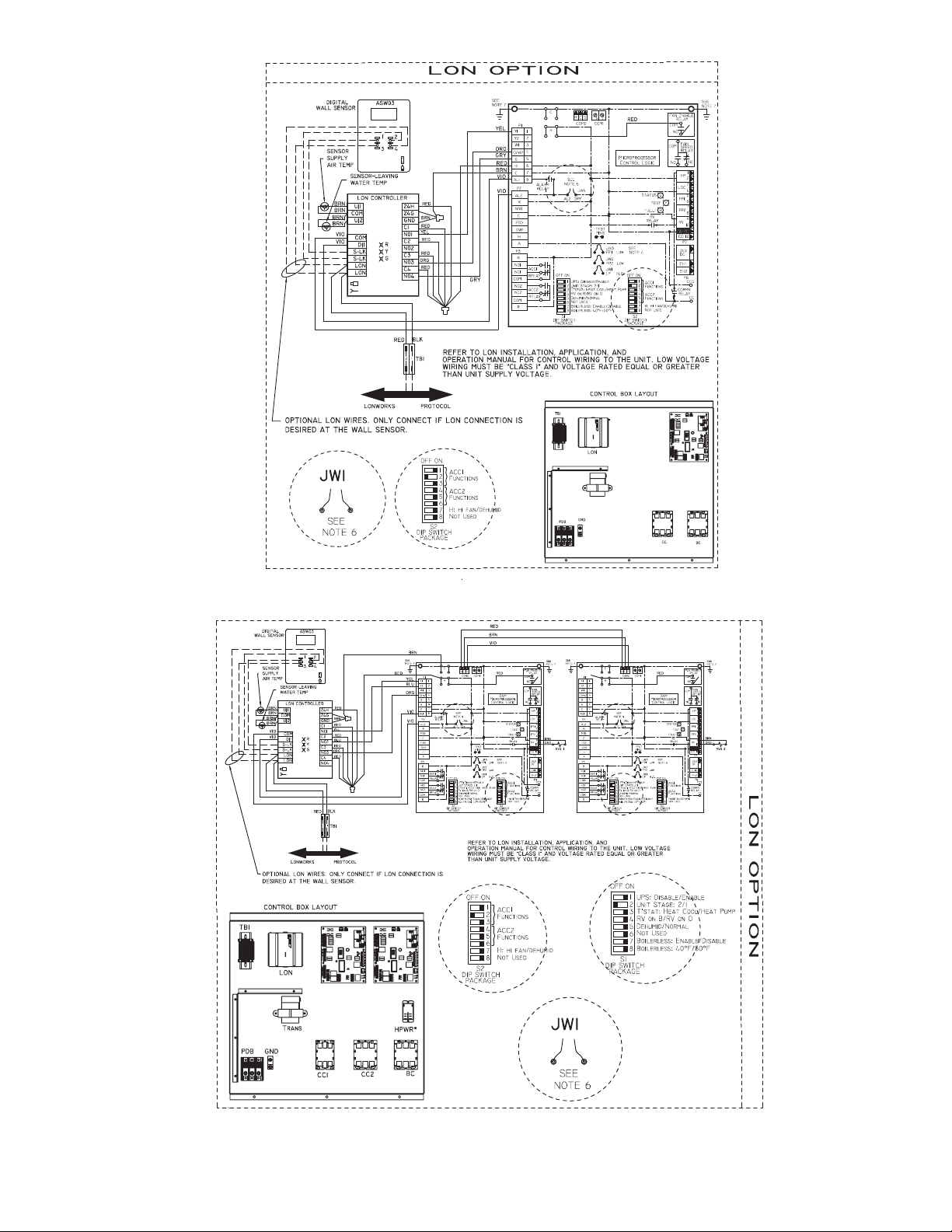
Deluxe D
Deluxe D
Deluxe D 1 Deluxe D 2
Fig. 11 — Typical Control Wiring with Deluxe D and LON Controller
SIZES 03-06
SIZES 08-20
a50-8558
29
Page 30

Y
W
O
G
R
C
AL1
AL2
A
CR
CMP1
FAN
PWR
HS1/EXH/RVS
PREMIER
LINK
CR
COMPLETE
C
CONTROL
J4
J6
J5
J8
J1
PWR
S
P
S
A
L
W
CMPSAFE
T
T
T
Y1
G
R
C
AL1
CMP1
FAN
PWR
PREMIER
LINK
DELUXE
D
CONTROL
J4
J8
J1
PWR
CMPSAFE
HS2
HS1
CMP2
Y2
W1
O/W2
J6
J5
S
P
T
S
A
T
L
W
T
Fig. 12 — Premierlink™ Controller Applications Wiring with Complete C Control
LEGEND
NOTE: Reversing valve is on in Cooling
mode.
CR — Control Relay
LWT — Leaving Water Temperature Sensor
SAT — Supply Air Temperature Sensor
SPT — Space Temperature Sensor
Fig. 13 — Premierlink Controller Applications Wiring with Deluxe D Control
LEGEND
NOTE: Reversing valve is on in Cooling
mode.
LWT — Leaving Water Temperature Sensor
SAT — Supply Air Temperature Sensor
SPT — Space Temperature Sensor
30
Page 31

WHSP-OPEN
10
PRIMARY
PRIMARY
Fig. 14 — Units with Complete C and WSHP Open Multiple Protocol Controls
A50-8355
LEGEND
BM — Blower Motor
BR — Blower Relay
CO — Condensate Overflow
FSD — Fire/Smoke Detector
LWT — Leaving Water Temperature
N.C. — Normally Closed
OAD — Outside Air Damper
OCC — Occupancy Input Contact
RH — Relative Humidity
SAT — Supply Air Temperature
SPT — Space Temperature
31
Page 32

PRIMARY
Fig. 15 — Units with Deluxe D and WSHP Open Multiple Protocol Controls
A50-8354
LEGEND
BM — Blower Motor
BR — Blower Relay
CO — Condensate Overflow
FSD — Fire/Smoke Detector
LWT — Leaving Water Temperature
N.C. — Normally Closed
OAD — Outside Air Damper
OCC — Occupancy Input Contact
RH — Relative Humidity
SAT — Supply Air Temperature
SPT — Space Temperature
PRIMARY
WSHP-OPEN
32
Page 33

012207-1BT485BT
LED1
DB
Install BT485 where device is
located at the end of network
segment only.
+ 24vac
(If not installed, it must be connected to DO-5)
DEHUMIDIFY OUTPUT CONTACT (DO-6) (FACTORY OPTION)
FAN SPEED (DO-7) (MED OR LOW)
OA DAMPER (AO-2)
FAN SPEED (DO-8) (HIGH OR FAN ON )
LWT (Input 6)
SAT (LAT) (Input 7)
SPACE CO2
SENSOR
+24vac
4-20mA
+
-
AO1 – Aux Reheat or Cond.
WTR. Loop Econ. (AO 1)
-Gnd
Fan (DO-1) (Fan On or Low Speed)
Aux Heat (DO-2)
Reversing Valve (DO-3)
Comp #2 (DO-4)
Comp #1 (DO-5)
Comp Status (DI-5)
SPT PLUS Sensor
Shown
+12V
Rnet-
Rnet+
Gnd
RED
BLACK
WHITE
GREEN
To WSHP Controller
Rnet Terminals (J13)
FIELD INSTALLED
0
5
1
6
2
7
3
8
4
9
0
5
1
6
2
7
3
8
4
9
12
3 45
6
7 8
O
N
1
2 3
4
5
67
8
12
1
2
3
4
123 4
1
2 3
123 45678
GREEN
WHITE
BLACK
RED
Field Installed
J5
J12
J13
J20
J19
J22
J17
J11
J14
To
SPT PLUS
1
2
3
45
6
1
1
10
7
J4
J1 J2
SW3
MSB
LSB
MSTP Baud
9600 19.2k 38.4k 76.8k
SPACE RH
SENSOR
+24vac
4-20mA
+
-
FIELD INSTALLED (OPTIONAL) – SEE NOTE 2
Local Access Port
(FIELD-INSTALLED)
PRIMARY
PRIMARY
CONDENSATE
OVERFLOW SWITCH
REMOTE OCCUPANCY/
FAN STATUS SWITCH
(FIELD-INSTALLED)
NC FIRE/SMOKE
DETECTOR CONTACT
(FIELD-INSTALLED)
Fig. 16 — WSHP Open Control
WSHP Open Inputs and Outputs Table
*These inputs are configurable.
INPUT/OUTPUT TYPE PART NUMBERS TYPE OF I/O
CONNECTION
PIN NUMBERS
CHANNEL
DESIGNATION
Inputs
Space Temperature Sensor SPS, SPPL, SPP Communicating J13, 1 - 4 Local Access Port
Space Relative Humidity 33ZCSENSRH-01 AI (4 - 20mA) J4, 5 and 6 Analog Input 1
Indoor Air Quality 33ZCSENCO2 AI (4 -20mA) J4, 2 and 3 Analog Input 2
Condensate Switch N/A BI (Dry Contacts) J1, 2 Binary Input 3
Stage 1 Compressor Status N/A BI (Dry Contacts) J1, 10 Binary Input 5
Leaving Condenser Water Temperature 10K Type II AI (10K Thermistor) J2, 1 and 2 Analog Input 6
Supply Air Temperature 33ZCSENSAT AI (10K Thermistor) J2, 3 and 4 Analog Input 7
Outputs
Modulating Valve (Auxiliary Heat/Water
Economizer)
N/A AO (0-10Vdc/2 - 10Vdc) J2 4 and 5* Analog Output 1
Outside Air Damper N/A AO (0-10Vdc/2 - 10Vdc) J22 1 and 2* Analog Output 2
Supply Fan On/Low Speed
(3 Speed Only)
N/A BO Relay (24VAC, 1A) J1, 4* Binary Output 1 (G)
Auxiliary Heat or 2-Position Water Loop
Economizer
N/A BO Relay (24VAC, 1A) J1, 5* Binary Output 2
Reversing Valve (B or O Operation) N/A BO Relay (24VAC, 1A) J1, 6* Binary Output 3 (RV)
Compressor 2nd Stage N/A BO Relay (24VAC, 1A) J1, 7 Binary Output 4 (Y2)
Compressor 1st Stage N/A BO Relay (24VAC, 1A) J1, 8 Binary Output 5 (Y1)
Dehumidification Relay N/A BO Relay (24VAC, 1A) J11, 7 and 8 (NO) Binary Output 6
Fan Speed Medium/Low (3 Speed Only) N/A BO Relay (24VAC, 1A) J11, 5 and 6 (NO)* Binary Output 7
Fan Speed High/Low (3 Speed Only) N/A BO Relay (24VAC, 1A) J11, 2 and 3 (NO)* Binary Output 8
LEGEND
NOTES:
1. Mount the water source heat pump controller in the equipment controls enclosure
with at least two no. 6 x 1 in. self-tapping screws. Allow adequate clearance for wiring.
2. Verify sensor power and wiring requirements prior to making any terminations. Sen-
sors requiring a separate isolated 24 vac power source will not utilize WSHP termi-
nals J4-1, or 4.
AI — Analog Input
AO — Analog Output
BI — Binary Input
BO — Binary Output
SPT — Space Temperature
Factory Wiring
Field Wiring
33
Page 34

Step 8 — Connect Low Voltage Wiring
Capacitor
Circ Brkr
Grnd
Contactor-CC
L2
L1
Transformer
CB
Aquazone “C”
See Note
Low Voltage
Connector
THERMOSTAT
WIRED DIRECTLY
TO CONTROL
BOARD
BR
NOTE: Low voltage connector may be removed for easy installation.
Fig. 17 — Low Voltage Field Wiring
THERMOSTAT
Compressor-Stage 1
Reversing Valve
Fan
24Vac Hot
Y1
Y2
O
G
R
Y
O
G
R
CompleteC 1
Y
O
G
R
24Vac Com
C
C
Compressor-Stage 2
C
AL
AL
AL
CompleteC 2
Fig. 18 — Thermostat Wiring to Complete C Board
THERMOSTAT
Compressor-Stage 1
Reversing Valve
Fan
24Vac Hot
Y1
Y2
O
G
R
O
G
R
Deluxe D 1
Y
O
G
R
24Vac Com
C
C
Compressor-Stage 2
C
AL1
AL1
AL
Y1
Y2
COM 2
COM 2
Deluxe D 2
Fig. 19 — Thermostat Wiring to Deluxe D Board
TYPICAL
WATER
VALVE
C
A
24 VAC
TERMINAL STRIP P2
AQUAZONE CONTROL (C Control Shown)
Fig. 20 — Typical Aquazone Control Board
Jumper Locations
Fig. 21 — Typical D Control Accessory Wiring
THERMOSTAT CONNECTIONS — The thermostat should
be wired directly to the Aquazone™ control board. See
Fig. 17-19.
WATER FREEZE PROTECTION — The Aquazone control
allows the field selection of source fluid freeze protection
points through jumpers. The factory setting of jumper JW3
(FP1) is set for water at 30 F. In earth loop applications, jumper
JW3 should be clipped to change the setting to 13 F when
using antifreeze in colder earth loop applications. See Fig. 20.
AIR COIL FREEZE PROTECTION — The air coil freeze
protection jumper JW2 (FP2) is factory set for 30 F and should
not need adjusting, unless using anti-freeze.
ACCESSORY CONNECTIONS — Terminal labeled A on
the control is provided to control accessory devices such as
water valves, electronic air cleaners, humidifiers, etc. This signal operates with the compressor terminal. See Fig. 21. Refer
to the specific unit wiring schematic for details.
NOTE: The A terminal should only be used with 24 volt
signals — not line voltage signals.
WATER SOLENOID VALVES — Water solenoid valves may
be used on primary secondary pump and ground water installations. A typical well water control valve wiring which can
limit waste water in a lockout condition is shown in Fig. 21. A
slow closing valve may be required to prevent water hammer.
When using a slow closing valve, special wiring conditions
need to be considered. The valve takes approximately 60 seconds to open (very little water will flow before 45 seconds) and
it activates the compressor only after the valve is completely
opened by closing its end switch. When wired as shown, the
valve will have the following operating characteristics:
1. Remain open during a lockout.
2. Draw approximately 25 to 35 VA through the “Y” signal
of the thermostat.
IMPORTANT: This can overheat the anticipators of
electromechanical thermostats. Only use relay based
electronic thermostats.
34
Page 35

PRE-START-UP
System Checkout —
and the system is cleaned and flushed, follow the System
Checkout procedure outlined below.
1. Voltage: Ensure that the voltage is within the utilization
range specifications of the unit compressor and fan motor.
2. System Water Temperature: Ensure that the system
water temperature is within an acceptable range to facilitate start-up. (When conducting this check, also verify
proper heating and cooling set points.)
3. System Water pH: Verify system water acidity
(pH = 7.5 or 8.5). Proper pH promotes the longevity of
hoses and heat exchangers.
4. System Flushing: Properly clean and flush the system
periodically. Ensure that all supply and return hoses are
connected end-to-end to facilitate system flushing and
prevent fouling of the heat exchanger by system water.
Water used in the system must be potable and should not
contain dirt, piping slag, and chemical cleaning agents.
5. Closed-Type Cooling Tower or Open Tower with Heat
Exchanger: Check equipment for proper temperature set
points and operation.
6. Verify Balanced Water Flow Rate to Heat Pump.
7. Standby Pump: Verify that the standby pump is properly
installed and in operating condition.
8. Access Panels: Assure that all access panels in the filter
and fan section are securely closed.
9. Air Dampers: Assure that all air dampers are properly
set.
10. System Controls: To ensure that no catastrophic system
failures occur, verify that system controls are functioning
and that the sequencing is correct.
11. Freeze Protection for Water System: Verify that freeze
protection is provided for the building loop water system
when outdoor design conditions require it. Inadequate
freeze protection can lead to expensive tower and system
piping repairs.
12. System Water Loop: Verify that all air is bled from the
system. Air in the system impedes unit operation and
causes corrosion in the system piping.
13. Unit Filters: To avoid system damage, check that the unit
filter is clean.
14. Unit Fans: Manually rotate fans to assure free rotation.
Ensure that fans are properly secured to the fan shaft. Do
not oil fan motors on start-up since they are lubricated at
the factory.
15. System Control Center: Examine the system control
and alarm panel for proper installation and operation to
ensure control of the temperature set-points for operation
of the system’s heat rejector and boiler (when used).
16. Miscellaneous: Note any questionable aspects of the
installation.
17. Air Coil: To obtain maximum performance, the air coil
should be cleaned before starting the unit. A ten percent
solution of dishwasher detergent and water is recommended for both sides of the coil. Rinse thoroughly with
water.
When the installation is complete
FIELD SELECTABLE INPUTS
Jumpers and DIP (dual in-line package) switches on the
control board are used to customize unit operation and can be
configured in the field.
IMPORTANT: Jumpers and DIP switches should only
be clipped when power to control board has been turned
off.
Complete C Control Jumper Settings (See
Fig. 6 and 7)
WATER COIL FREEZE PROTECTION (FP1) LIMIT
SETTING — Select jumper 3, (JW3-FP1 Low Temp) to
choose FP1 limit of 10 F or 30 F. To select 30 F as the limit,
DO NOT clip the jumper. To select 10 F as the limit, clip the
jumper.
AIR COIL FREEZE PROTECTION (FP2) LIMIT SETTING — Select jumper 2 (JW2-FP2 Low Temp) to choose
FP2 limit of 10 F or 30 F. To select 30 F as the limit, DO NOT
clip the jumper. To select 10 F as the limit, clip the jumper.
ALARM RELAY SETTING — Select jumper 1 (JW1-AL2
Dry) for connecting alarm relay terminal (AL2) to 24 vac (R)
or to remain as a dry contact (no connection). To connect AL2
to R, do not clip the jumper. To set as dry contact, clip the
jumper.
Complete C Control DIP Switches — The Com-
plete C control has 1 DIP switch block with two switches. See
Fig. 6 and 7.
PERFORMANCE MONITOR (PM) — DIP switch 1 will
enable or disable this feature. To enable the PM, set the switch
to ON. To disable the PM, set the switch to OFF.
STAGE 2 — DIP switch 2 will enable or disable compressor
delay. Set DIP switch to OFF for stage 2 in which the compressor will have a 3-second delay before energizing.
NOTE: The alarm relay will not cycle during Test mode if
switch is set to OFF, stage 2.
Deluxe D Control Jumper Settings (See Fig. 9
and 10)
WATER COIL FREEZE PROTECTION (FP1) LIMIT
SETTING — Select jumper 3, (JW3-FP1 Low Temp) to
choose FP1 limit of 10 F or 30 F. To select 30 F as the limit, DO
NOT clip the jumper. To select 10 F as the limit, clip the jumper.
AIR COIL FREEZE PROTECTION (FP2) LIMIT SETTING — Select jumper 2 (JW2-FP2 Low Temp) to choose
FP2 limit of 10 F or 30 F. To select 30 F as the limit, DO NOT
clip the jumper. To select 10 F as the limit (for anti-freeze systems), clip the jumper.
ALARM RELAY SETTING — Select jumper 4 (JW4-AL2
Dry) for connecting alarm relay terminal (AL2) to 24 vac (R)
or to remain as a dry contact (no connection). To connect AL2
to R, do not clip the jumper. To set as dry contact, clip the
jumper.
LOW PRESSURE SETTING — The Deluxe D control can
be configured for Low Pressure Setting (LP). Select jumper 1
(JW1-LP Norm Open) for choosing between low pressure input normally opened or closed. To configure for normally
closed operation, do not clip the jumper. To configure for normally open operation, clip the jumper.
Deluxe D Control DIP Switches — The Deluxe D
control has 2 DIP switch blocks. Each DIP switch block has 8
switches and is labeled either S1 or S2 on the circuit board.
DIP SWITCH BLOCK 1 (S1) — This set of switches offers
the following options for Deluxe D control configuration:
Performance Monitor (PM)
able performance monitor. To enable the PM, set the switch to
ON. To disable the PM, set the switch to OFF.
Compressor Relay Staging Operation
able or disable compressor relay staging operation. The compressor relay can be set to turn on with stage 1 or stage 2 call
— Set switch 1 to enable or dis-
— Switch 2 will en-
35
Page 36

from the thermostat. This setting is used with dual stage units
(units with 2 compressors and 2 Deluxe D controls) or in master/slave applications. In master/slave applications, each compressor and fan will stage according to its switch 2 setting. If
switch is set to stage 2, the compressor will have a 3-second delay before energizing during stage 2 demand.
NOTE: If DIP switch is set for stage 2, the alarm relay will not
cycle during Test mode.
Heating/Cooling Thermostat Type
— Switch 3 provides selection of thermostat type. Heat pump or heat/cool thermostats
can be selected. Select OFF for heat/cool thermostats. When in
heat/cool mode, Y1 is used for cooling stage 1, Y2 is used for
cooling stage 2, W1 is used for heating stage 1 and O/W2 is
used for heating stage 2. Select ON for heat pump applications.
In heat pump mode, Y1 used is for compressor stage 1, Y2 is
used for compressor stage 2, W1 is used for heating stage 3 or
emergency heat, and O/W2 is used for RV (heating or cooling)
depending upon switch 4 setting.
O/B Thermostat Type
— Switch 4 provides selection for heat
pump O/B thermostats. O is cooling output. B is heating output. Select ON for heat pumps with O output. Select OFF for
heat pumps with B output.
Dehumidification Fan Mode
— Switch 5 provides selection of
normal or dehumidification fan mode. Select OFF for dehumidification mode. The fan speed relay will remain OFF during cooling stage 2. Select ON for normal mode. The fan speed
relay will turn on during cooling stage 2 in normal mode.
Switch 6
Boilerless Operation
— Not used.
— Switch 7 provides selection of boilerless operation and works in conjunction with switch 8. In
boilerless operation mode, only the compressor is used for
heating when FP1 is above the boilerless changeover temperature set by switch 8 below. Select ON for normal operation or
select OFF for boilerless operation.
Boilerless Changeover Temperature
— Switch 8 on S1 provides selection of boilerless changeover temperature set point.
Select OFF for set point of 50 F or select ON for set point
of 40 F.
If switch 8 is set for 50 F, then the compressor will be used
for heating as long as the FP1 is above 50 F. The compressor
will not be used for heating when the FP1 is below 50 F and the
compressor will operates in emergency heat mode, staging on
EH1 and EH2 to provide heat. If a thermal switch is being used
instead of the FP1 thermistor, only the compressor will be used
for heating mode when the FP1 terminals are closed. If the FP1
terminals are open, the compressor is not used and the control
goes into emergency heat mode.
DIP SWITCH BLOCK 2 (S2) — This set of DIP switches is
used to configure accessory relay options.
Switches 1 to 3
— These DIP switches provide selection
of Accessory 1 relay options. See Table 13 for DIP switch
combinations.
Switches 4 to 6
— These DIP switches provide selection
of Accessory 2 relay options. See Table 14 for DIP switch
combinations.
Auto Dehumidification Mode or High Fan Mode
— Switch
7 provides selection of auto dehumidification fan mode or high
fan mode. In auto dehumidification fan mode the fan speed relay will remain off during cooling stage 2 if terminal H is active. In high fan mode, the fan enable and fan speed relays will
turn on when terminal H is active. Set the switch to ON for
auto dehumidification fan mode or to OFF for high fan mode.
Switch 8
— Not used.
Table 13 — DIP Switch Block S2 —
Accessory 1 Relay Options
ACCESSORY 1
RELAY OPTIONS
Cycle with Fan On On On
Digital NSB Off On On
Water Valve — Slow Opening On Off On
OAD On On Off
LEGEND
NSB — Night Setback
OAD — Outside Air Damper
NOTE: All other DIP switch combinations are invalid.
DIP SWITCH POSITION
123
Table 14 — DIP Switch Block S2 —
Accessory 2 Relay Options
ACCESSORY 2
RELAY OPTIONS
Cycle with Fan On On On
Digital NSB Off On On
Water Valve — Slow Opening On Off On
OAD On On Off
LEGEND
NSB — Night Setback
OAD — Outside Air Damper
NOTE: All other switch combinations are invalid.
DIP SWITCH POSITION
456
Deluxe D Control Accessory Relay Configurations — The following accessory relay settings are applica-
ble for both Deluxe D controls only:
CYCLE WITH FAN — In this configuration, the relay will be
ON any time the Fan Enable relay is on.
CYCLE WITH COMPRESSOR — In this configuration, the
relay will be ON any time the Compressor relay is on.
DIGITAL NIGHT SET BACK (NSB) — In this configura-
tion, the relay will be ON if the NSB input is connected to
ground C.
NOTE: If there are no relays configured for digital NSB, then
the NSB and OVR inputs are automatically configured for
mechanical operation.
MECHANICAL NIGHT SET BACK — When NSB input is
connected to ground C, all thermostat inputs are ignored. A
thermostat set back heating call will then be connected to the
OVR input. If OVR input becomes active, then the Deluxe D
control will enter Night Low Limit (NLL) staged heating
mode. The NLL staged heating mode will then provide heating
during the NSB period.
Water Valve (Slow Opening) — If relay is config-
ured for Water Valve (slow opening), the relay will start 60 seconds prior to starting compressor relay.
Outside-Air Damper (OAD) — If relay is configured
for OAD, the relay will normally be ON any time the Fan
Enable relay is energized. The relay will not start for 30 minutes following a return to normal mode from NSB, when NSB
is no longer connected to ground C. After 30 minutes, the relay
will start if the Fan Enable is set to ON.
CAUTION
To avoid equipment damage, DO NOT leave system filled
in a building without heat during the winter unless antifreeze is added to system water. Condenser coils never
fully drain by themselves and will freeze unless winterized
with antifreeze.
36
Page 37

START-UP
Use the procedure outlined below to initiate proper unit
start-up.
NOTE: This equipment is designed for indoor installation only.
Operating Limits
ENVIRONMENT — This equipment is designed for outdoor
installation ONLY. Extreme variations in temperature, humidity and corrosive water or air will adversely affect the unit performance, reliability and service life.
POWER SUPPLY — A voltage variation of ± 10% of nameplate utilization voltage is acceptable.
UNIT STARTING CONDITIONS — See Table 15 for unit
starting conditions.
Table 15 — Starting Conditions — 50RTP Units
AIR LIMITS COOLING HEATING
Minimum Entering Air 40 F 40 F
Maximum Entering Air (db) 110 F 80 F
WATER LIMITS
Minimum Entering Fluid 40 F 20 F
Maximum Entering Fluid 120 F 90 F
LEGEND
db — Dry Bulb
NOTE: These starting conditions are not normal or continuous
operating conditions. It is assumed that such a start-up is for
the purpose of bringing the building space up to occupancy
temperature. See Table 16 for operating limits.
WARNING
When the disconnect switch is closed, high voltage is present in some areas of the electrical panel. Exercise caution
when working with the energized equipment.
1. Restore power to system.
2. Turn thermostat fan position to ON. Blower should start.
3. Balance airflow at registers.
4. Adjust all valves to the full open position and turn on the
line power to all heat pump units.
5. Operate unit in the cooling cycle. Room temperature
should be approximately 70 to 75 F dry bulb. Loop water
temperature entering the heat pumps should be between
60 and 110 F.
NOTE: Three factors determine the operating limits of a unit:
(1) entering air temperature, (2) water temperature and (3)
ambient temperature. Whenever any of these factors are at a
minimum or maximum level, the other two factors must be at a
normal level to ensure proper unit operation. See Table 15.
Table 16 — Operating Limits — 50RTP Units
AIR LIMITS COOLING HEATING
Minimum Entering Air 60 F 50 F
Maximum Entering Air (db) 90 F 80 F
WATER LIMITS
Minimum Entering Fluid 40 F 20 F
Maximum Entering Fluid 120 F 90 F
LEGEND
db — Dry Bulb
Scroll Compressor Rotation — It is important to be
certain compressor is rotating in the proper direction. To
determine whether or not compressor is rotating in the proper
direction, perform the following procedure.
1. Connect service gages to suction and discharge pressure
fittings.
2. Energize the compressor.
3. The suction pressure should drop and the discharge
pressure should rise, as is normal on any start-up.
If the suction pressure does not drop and the discharge
pressure does not rise to normal levels:
1. Turn off power to the unit. Install disconnect tag.
2. Reverse any two of the unit power leads.
3. Reapply power to the unit and verify pressures are correct.
The suction and discharge pressure levels should now move
to their normal start-up levels.
When the compressor is rotating in the wrong direction, the
unit makes an elevated level of noise and does not provide
cooling.
After a few minutes of reverse operation, the scroll compressor internal overload protection will open, thus activating
the unit lockout. This requires a manual reset. To reset, turn the
thermostat on and then off.
NOTE: There is a 5-minute time delay before the compressor
will start.
Unit Start-Up Cooling Mode
1. Adjust the unit thermostat to the warmest position.
Slowly reduce the thermostat position until the compressor activates.
2. Check for cool air delivery at unit grille a few minutes
after the unit has begun to operate.
3. Verify that the compressor is on and that the water flow
rate is correct by measuring pressure drop through the
heat exchanger using P/T plugs. Check the elevation and
cleanliness of the condensate lines; any dripping could be
a sign of a blocked line. Be sure the condensate trap includes a water seal.
4. Check the temperature of both supply and discharge
water. If temperature is within range, proceed. If temperature is outside the range, check the cooling refrigerant
pressures.
5. Air temperature drop across the coil should be checked
when compressor is operating. Air temperature drop
should be between 15 and 25 F.
Unit Start-Up Heating Mode
NOTE: Operate the unit in heating cycle after checking the
cooling cycle. Allow five minutes between tests for the pressure or reversing valve to equalize.
1. Turn thermostat to lowest setting and set thermostat
switch to HEAT position.
2. Slowly turn the thermostat to a higher temperature until
the compressor activates.
3. Check for warm air delivery at the unit grille within a few
minutes after the unit has begun to operate.
4. Check the temperature of both supply and discharge
water. If temperature is within range, proceed. If temperature is outside the range, check the heating refrigerant
pressures.
5. Once the unit has begun to run, check for warm air delivery at the unit grille.
6. Air temperature rise across the coil should be checked
when compressor is operating. Air temperature rise
should be between 20 and 30 F after 15 minutes at load.
7. Check for vibration, noise and water leaks.
37
Page 38

Unit Start-Up with WSHP Open Controls —
Fig. 22 — BACview6 Display Interface
a50-8444
The WSHP Open is a multi-protocol (default BACnet*) controller with extensive features, flexible options and powerful
capabilities. The unit comes from the factory pre-programmed
and needs minimal set up to function in a BAS (Building
Automation System) system or provide additional capabilities
to Carrier's WSHP product line. Most settings on the controller
have factory defaults set for ease of installation. There are a
few settings that must be configured in the field and several
settings that can be adjusted if required by unique job conditions. Refer to Appendix A — WSHP Open Screen Configuration. In order to configure the unit, a BACview
required. See Fig. 22.
NOTE: If the WSHP Open control has lost its programming,
all display pixels will be displayed on the SPT sensor. See the
WSHP Third Party Integration Guide.
When the unit is OFF, the SPT sensor will indicate OFF.
When power is applied, the SPT sensor will indicate temperature in the space at 78 F.
To start up a unit with WSHP Open controls:
1. To plug in the BACview
6
handheld display into a SPT
sensor, point the two ears on the connector up and tilt the
bottom of the plug toward you. Insert the plug up into the
SPT sensor while pushing the bottom of the plug away
from you.
2. BACview
6
should respond with "Establishing Connection." The Home screen will then appear on the display
showing operating mode and space temperature. Press
any button to continue.
See Appendix A — WSHP Open Screen Configuration
for the hierarchal structure of the WSHP Open controller.
All functions of the controller can be set from the Home
screen.
3. When the Login is requested, type 1111 and push the OK
softkey. The Logout will then be displayed to indicate the
password was accepted.
4. To set the Clock if it is not already displayed:
a. Select System Settings from the Home screen, then
press Clockset.
b. Scroll to hour, minute and second using the arrow
keys. Use the number keypad to set actual time.
c. Scroll to day, month and year using arrow keys.
Use number keypad to set date.
5. To set Daylight Savings Time (DST):
a. Push the DST softkey. The display will indicate
02:00:060 which is equal to 2:00AM.
6
display is
b. To program the beginning and end dates, scroll
down to the beginning month and press the enter
key. The softkeys (INCR and DECR) will activate
to increment the month in either direction, Jan,
Feb, March, etc.
c. Use number keys to select the day of month and
year.
d. Push the OK softkey to finalize the data.
6. To view configuration settings:
a. Select the Config softkey.
b. Select the Service Config softkey. Scroll through
the factory settings by using the up and down
arrow keys. See below for factory settings.
Only the following settings will need to be
checked.
• # of Fan Speeds — This should be set to "1" for
units with PSC motors and set to "3" for units with
ECM motors.
• Compressor Stages — This should be set to "1."
• Factory Dehumidification Reheat Coil — This
should be set to "none" unless the modulating hot
water reheat option is supplied in the unit, then set
to "installed."
• The condenser water limit needs to be verified
depending on design parameters and application,
whether geothermal or boiler/tower.
7. To view unit configuration settings:
a. Select the Unit Configuration softkey, then select
Unit.
b. Scroll through the unit settings by using the up and
down arrow keys. Unit settings include:
• Fan Mode: Default Continuous
• Fan Delay:
• Minimum SAT Cooling: Default 50 F
• Maximum SAT Heating: Default 110 F
• Filter Service Alarm: Must be set from 0 to 9999 hr
8. To set local schedules:
a. Select the Schedule softkey from the Configuration
screen, then press enter.
b. Select Weekly, then press enter (7 schedules
available).
c. Select day and press enter.
d. Press enter again and select ADD or DEL (DECR
or INCR) set schedule.
*Sponsored by ASHRAE (American Society of Heating, Refrigerating,
and Air Conditioning Engineers).
38
Page 39

e. Enter ON/OFF time, then press continue.
f. Press OK to apply and save to a particular day of
the week.
g. Continue to add the same or different schedule spe-
cific days of the week.
To add exceptions to the schedule:
i. Press Add softkey.
ii. Select exception type from following:
• Date
• Date Range
• Week-N-Day
• Calender Reference
9. Go back to Home Screen.
10. Remove BACview
the process in Step 1.
11. Perform system test.
6
cable from SPT sensor by reversing
Flow Regulation — Flow regulation can be accom-
plished by two methods. Most water control valves have a flow
adjustment built into the valve. By measuring the pressure drop
through the unit heat exchanger, the flow rate can be determined. Adjust the water control valve until the flow of 1.5 to 2
gpm is achieved. Since the pressure constantly varies, two
pressure gages may be needed in some applications.
An alternative method is to install a flow control device.
These devices are typically an orifice of plastic material designed to allow a specified flow rate that are mounted on the
outlet of the water control valve. Occasionally these valves
produce a velocity noise that can be reduced by applying some
back pressure. To accomplish this, slightly close the leaving
isolation valve of the well water setup.
WARNING
Electrical shock can cause personal injury and death. Shut
off all power to this equipment during installation. There
may be more than one disconnect switch. Tag all disconnect locations to alert others not to restore power until
flushing is completed.
System Cleaning and Flushing — Cleaning and
flushing the unit is the single most important step to ensure
proper start-up and continued efficient operation of the system.
Follow the instructions below to properly clean and flush the
system:
1. Verify that electrical power to the units is disconnected.
2. Install the system with the supply hose connected directly
to the return riser valve. Use a single length of flexible
hose.
3. Open all air vents. Fill the system with water. Do not allow system to overflow. Bleed all air from the system.
Check the system for leaks and repair appropriately.
4. Verify that all strainers are in place. Start the pumps and
systematically check each vent to ensure that all air is
bled from the system.
5. Verify that makeup water is available. Adjust makeup
water appropriately to replace the air which was bled
from the system. Check and adjust the water/air level in
the expansion tank.
6. Set the boiler (when used) to raise the loop temperature to
approximately 85 F. Open a drain at the lowest point in
the system. Adjust the makeup water replacement rate to
equal the rate of bleed.
7. Refill the system and add trisodium phosphate in a proportion of approximately one pound per 150 gallons of
water. Reset the boiler (when used) to raise the loop temperature to about 100 F. Circulate the solution for a
minimum of eight to 24 hours. At the end of this period,
shut off the circulating pump and drain the solution. Repeat system cleaning if necessary.
CAUTION
To avoid possible damage to piping systems constructed of
plastic piping, DO NOT allow loop temperature to exceed
115 F.
8. When the cleaning process is complete, remove the shortcircuited hoses. Reconnect the hoses to the proper supply
and return the connections to each of the rooftop units.
Refill the system and bleed off all air.
9. Add antifreeze to the system in climates where ambient
temperature falls below freezing, using the proportion of
antifreeze shown in Table 17. The volume of antifreeze
required will vary based on outdoor design temperature.
10. Test the system pH with litmus paper. The system water
should be slightly alkaline ( pH 7.5 to 8.5). Add chemicals as appropriate to maintain acidity levels.
11. When the system is successfully cleaned, flushed, refilled
and bled, check the main system panels, safety cutouts,
and alarms. Set the controls to properly maintain loop
temperatures.
NOTE: Carrier strongly recommends all piping connections,
both internal and external to the unit, be pressure tested by an
appropriate method prior to any finishing of the interior space
or before access to all connections is limited. Test pressure
may not exceed the maximum allowable pressure for the unit
and all components within the water system.
Carrier will not be responsible or liable for damages from
water leaks due to inadequate or lack of a pressurized leak test,
or damages caused by exceeding the maximum pressure rating
during installation.
CAUTION
Do Not use “Stop-Leak” or any similar chemical agent in
this system. Addition of these chemicals to the loop water
will foul the system and will inhibit unit operation.
Antifreeze — In areas where entering loop temperatures
drop below 40 F or where piping will be routed through areas
subject to freezing, antifreeze is needed.
Alcohols and glycols are commonly used as antifreeze
agents. Freeze protection should be maintained to 15 F below
the lowest expected entering loop temperature. For example, if
the lowest expected entering loop temperature is 30 F, the leaving loop temperature would be 22 to 25 F. Therefore, the freeze
protection should be at 15 F (30 F – 15 F = 15 F).
IMPORTANT: All alcohols should be pre-mixed and
pumped from a reservoir outside of the building or
introduced under water level to prevent fumes.
Calculate the total volume of fluid in the piping system. Use
the percentage by volume in Table 17 to determine the amount
of antifreeze to use. Antifreeze concentration should be
checked from a well mixed sample using a hydrometer to measure specific gravity.
FREEZE PROTECTION SELECTION — The 30 F FP1 factory setting (water) should be used to avoid freeze damage to
the unit.
Once antifreeze is selected, the JW3 jumper (FP1) should
be clipped on the control to select the low temperature (antifreeze 13 F) set point to avoid nuisance faults.
39
Page 40

Table 17 — Antifreeze Percentages by Volume
MINIMUM TEMPERATURE FOR
ANTIFREEZE
Methanol (%) 25 21 16 10
Propylene Glycol (%) 26 23 19 9
Ethylene Glycol (%) 24 20 16 12
FREEZE PROTECTION (F)
0° 10 20 30
Cooling Tower/Boiler Systems — These systems
typically use a common loop maintained at 60 to 90 F. The use
of a closed circuit evaporative cooling tower with a secondary
heat exchanger between the tower and the water loop is recommended. If an open type cooling tower is used continuously,
chemical treatment and filtering will be necessary.
Ground Coupled, Closed Loop and Plateframe
Heat Exchanger Well Systems — These systems al-
low water temperatures from 30 to 110 F. The external loop
field is divided up into 2 in. polyethylene supply and return
lines. Each line has valves connected in such a way that upon
system start-up, each line can be isolated for flushing using
only the system pumps. Air separation should be located in the
piping system prior to the fluid re-entering the loop field.
OPERATION
Power Up Mode —
inputs, terminals and safety controls are checked for normal
operation.
NOTE: The compressor will have a 5-minute anti-short cycle
upon power up.
The unit will not operate until all the
Units with Aquazone™ Complete C Control
STANDBY — Y and W terminals are not active in standby
mode, however the O and G terminals may be active, depending on the application. The compressor will be off.
COOLING — Y and O terminals are active in Cooling mode.
After power up, the first call to the compressor will initiate a
5 to 80 second random start delay and a 5-minute anti-short
cycle protection time delay. After both delays are complete, the
compressor is energized.
NOTE: On all subsequent compressor calls the random start
delay is omitted.
HEATING STAGE 1 — Terminal Y is active in heating
stage 1. After power up, the first call to the compressor will
initiate a 5 to 80 second random start delay and a 5-minute antishort cycle protection time delay. After both delays are
complete, the compressor is energized.
NOTE: On all subsequent compressor calls the random start
delay is omitted.
HEATING STAGE 2 — To enter Stage 2 mode, terminal W is
active (Y is already active). Also, the G terminal must be active
or the W terminal is disregarded. The compressor relay will remain on and EH1 is immediately turned on. EH2 will turn on
after 10 minutes of continual stage 2 demand.
NOTE: EH2 will not turn on (or if on, will turn off) if FP1 temperature is greater than 45 F and FP2 is greater than 110 F.
EMERGENCY HEAT — In emergency heat mode, terminal
W is active while terminal Y is not. Terminal G must be active
or the W terminal is disregarded. EH1 is immediately turned
on. EH2 will turn on after 5 minutes of continual emergency
heat demand.
Units with Aquazone Deluxe D Control
STANDBY/FAN ONLY — The compressor will be off. The
Fan Enable, Fan Speed, and reversing valve (RV) relays will be
on if inputs are present. If there is a Fan 1 demand, the Fan
Enable will immediately turn on. If there is a Fan 2 demand,
the Fan Enable and Fan Speed will immediately turn on.
NOTE: DIP switch 5 on S1 does not have an effect upon Fan 1
and Fan 2 outputs.
HEATING STAGE 1 — In Heating Stage 1 mode, the Fan
Enable and Compressor relays are turned on immediately.
Once the demand is removed, the relays are turned off and the
control reverts to Standby mode. If there is a master/slave or
dual compressor application, all compressor relays and related
functions will operate per their associated DIP switch 2 setting
on S1.
HEATING STAGE 2 — In Heating Stage 2 mode, the Fan
Enable and Compressor relays remain on. The Fan Speed relay
is turned on immediately and turned off immediately once the
demand is removed. The control reverts to Heating Stage 1
mode. If there is a master/slave or dual compressor application,
all compressor relays and related functions will operate per
their associated DIP switch 2 setting on S1.
HEATING STAGE 3 — In Heating Stage 3 mode, the Fan
Enable, Fan Speed and Compressor relays remain on. The EH1
output is turned on immediately. With continuing Heat Stage 3
demand, EH2 will turn on after 10 minutes. EH1 and EH2 are
turned off immediately when the Heating Stage 3 demand is removed. The control reverts to Heating Stage 2 mode.
Output EH2 will be off if FP1 is greater than 45 F AND
FP2 (when shorted) is greater than 110 F during Heating
Stage 3 mode. This condition will have a 30-second recognition time. Also, during Heating Stage 3 mode, EH1, EH2, Fan
Enable, and Fan Speed will be ON if G input is not active.
EMERGENCY HEAT — In Emergency Heat mode, the Fan
Enable and Fan Speed relays are turned on. The EH1 output is
turned on immediately. With continuing Emergency Heat demand, EH2 will turn on after 5 minutes. Fan Enable and Fan
Speed relays are turned off after a 60-second delay. The control
reverts to Standby mode.
Output EH1, EH2, Fan Enable, and Fan Speed will be ON if
the G input is not active during Emergency Heat mode.
COOLING STAGE 1 — In Cooling Stage 1 mode, the Fan
Enable, compressor and RV relays are turned on immediately.
If configured as stage 2 (DIP switch set to OFF) then the compressor and fan will not turn on until there is a stage 2 demand.
The fan Enable and compressor relays are turned off immediately when the Cooling Stage 1 demand is removed. The control reverts to Standby mode. The RV relay remains on until
there is a heating demand. If there is a master/slave or dual
compressor application, all compressor relays and related functions will track with their associated DIP switch 2 on S1.
COOLING STAGE 2 — In Cooling Stage 2 mode, the Fan
Enable, compressor and RV relays remain on. The Fan Speed
relay is turned on immediately and turned off immediately
once the Cooling Stage 2 demand is removed. The control reverts to Cooling Stage 1 mode. If there is a master/slave or dual
compressor application, all compressor relays and related functions will track with their associated DIP switch 2 on S1.
NIGHT LOW LIMIT (NLL) STAGED HEATING — In NLL
staged Heating mode, the override (OVR) input becomes active and is recognized as a call for heating and the control will
immediately go into a Heating Stage 1 mode. With an additional 30 minutes of NLL demand, the control will go into Heating
Stage 2 mode. With another additional 30 minutes of NLL
demand, the control will go into Heating Stage 3 mode.
Units with WSHP Open Multiple Protocol —
The WSHP Open multi-protocol controller will control mechanical cooling, heating and waterside economizer outputs
based on its own space temperature input and set points. An
optional CO
space can maximize the occupant comfort. The WSHP Open
controller has its own hardware clock that is automatically set
IAQ (indoor air quality) sensor mounted in the
2
40
Page 41

when the heat pump software is downloaded to the board. Oc-
cupancy types are described in the scheduling section below.
The following sections describe the functionality of the WSHP
Open multi-protocol controller. All point objects referred to in
this sequence of operation will be referenced to the objects as
viewed in the BACview
6
handheld user interface.
SCHEDULING — Scheduling is used to start/stop the unit
based on a time period to control the space temperature to specified occupied heating and cooling set points. The controller is
defaulted to control by occupied set points all the time, until either a time schedule is configured with BACview
tant, i-Vu
®
Open, or a third party control system to enable/dis-
6
, Field Assis-
able the BAS (Building Automation System) on/off point. The
local time and date must be set for these functions to operate
properly. The occupancy source can be changed to one of the
following:
Occupancy Schedules
until a time schedule has been configured using either Field
Assistant, i-Vu Open, BACview
— The controller will be occupied 24/7
6
or a third party control system to enable/disable the BAS on/off point. The BAS point can
be disabled by going to Config, then Unit, then Occupancy
Schedules and changing the point from enable to disable then
clicking OK.
NOTE: This point must be enabled in order for the i-Vu Open,
Field Assistant, or BACview
6
control system to assign a time
schedule to the controller.
Schedule_schedule
schedule configured and stored in the unit. The schedule is
accessible via the BACview
— The unit will operate according to the
6
Handheld tool, i-Vu Open, or
Field Assistant control system. The daily schedule consists of a
start/stop time (standard or 24-hour mode) and seven days of
the week, starting with Monday and ending on Sunday. To
enter a daily schedule, navigate to Config, then Sched, then
enter BACview
6
Admin Password (1111), then go to
schedule_schedule. From here, enter either a Weekly or Exception schedule for the unit.
Occupancy Input Contact
— The WSHP Open controller has
the capability to use an external dry contact closure to determine the occupancy status of the unit. The Occupancy Schedules will need to be disabled in order to utilize the occupancy
contact input.
NOTE: Scheduling can only be controlled from one source.
BAS (Building Automation System) On/Off
— A BAS
system that supports network scheduling can control the unit
through a network communication and the BAS scheduling
function once the Occupancy Schedules have been disabled.
NOTE: Scheduling can either be controlled via the unit or the
BAS, but not both.
INDOOR FAN — The indoor fan will operate in any one of
three modes depending on the user configuration selected.
Fan mode can be selected as Auto, Continuous, or Always
On. In Auto mode, the fan is in intermittent operation during
both occupied and unoccupied periods. Continuous fan mode
is intermittent during unoccupied periods and continuous during occupied periods. Always On mode operates the fan continuously during both occupied and unoccupied periods. In the
default mode, Continuous, the fan will be turned on whenever
any one of the following is true:
• The unit is in occupied mode as determined by its occu-
pancy status.
• There is a demand for cooling or heating in the unoccu-
pied mode.
• There is a call for dehumidification (optional).
When power is reapplied after a power outage, there will be
a configured time delay of 5 to 600 seconds before starting the
fan. There are also configured fan delays for Fan On and Fan
Off. The Fan On delay defines the delay time (0 to 30 seconds;
default 10) before the fan begins to operate after heating or
cooling is started while the Fan Off delay defines the delay
time (0 to 180 seconds; default 45) the fan will continue to operate after heating or cooling is stopped. The fan will continue
to run as long as the compressors, heating stages, or the dehumidification relays are on. If the SPT failure alarm or condensate overflow alarm is active; the fan will be shut down immediately regardless of occupancy state or demand.
Fan Speed Control (During Heating)
— Whenever heat is required and active, the control continuously monitors the supply-air temperature to verify it does not rise above the configured maximum heating SAT limit (110 F default). As the SAT
approaches this value, the control will increase the fan speed as
required to ensure the SAT will remain within the limit. This
feature provides the most quiet and efficient operation by operating the fan at the lowest speed possible.
Fan Speed Control (During Cooling)
— Whenever mechanical cooling is required and active, the control continuously
monitors the supply-air temperature to verify it does not fall below the configured minimum cooling SAT limit (50 F default).
As the SAT approaches this value, the control will increase the
fan speed as required to ensure the SAT will remain within the
limit. The fan will operate at lowest speed to maximize latent
capacity during cooling.
COOLING — The WSHP Open controller will operate one or
two stages of compression to maintain the desired cooling set
point. The compressor outputs are controlled by the PI (proportional-integral) cooling loop and cooling stages capacity algorithm. They will be used to calculate the desired number of
stages needed to satisfy the space by comparing the space temperature (SPT) to the appropriate cooling set point. The water
side economizer, if applicable, will be used for first stage cooling in addition to the compressor(s). The following conditions
must be true in order for the cooling algorithm to run:
• Cooling is set to Enable.
• Heating mode is not active and the compressor time
guard has expired.
• Condensate overflow input is normal.
• If occupied, the SPT is greater than the occupied cooling
set point.
• Space temperature reading is valid.
• If unoccupied, the SPT is greater than the unoccupied
cooling set point.
• If economizer cooling is available and active and the
economizer alone is insufficient to provide enough
cooling.
• OAT (if available) is greater than the cooling lockout
temperature.
If all the above conditions are met, the compressors will be
energized as required, otherwise they will be deenergized. If
cooling is active and should the SAT approach the minimum
SAT limit, the fan will be indexed to the next higher speed.
Should this be insufficient and if the SAT falls further (equal to
the minimum SAT limit), the fan will be indexed to the maximum speed. If the SAT continues to fall 5 F below the minimum SAT limit, all cooling stages will be disabled.
During Cooling mode, the reversing valve output will be
held in the cooling position (either B or O type as configured)
even after the compressor is stopped. The valve will not switch
position until the Heating mode is required.
The configuration screens contain the minimum SAT
parameter as well as cooling lockout based on outdoor-air
temperature (OAT) Both can be adjusted to meet various
specifications.
There is a 5-minute off time for the compressor as well as a
5-minute time delay when staging up to allow the SAT to
achieve a stable temperature before energizing a second stage
of capacity. Likewise, a 45-second delay is used when staging
down.
41
Page 42

After a compressor is staged off, it may be restarted again
after a normal time-guard period of 5 minutes and if the
supply-air temperature has increased above the minimum
supply-air temperature limit.
The WSHP Open controller provides a status input to monitor the compressor operation. The status is monitored to determine if the compressor status matches the commanded state.
This input is used to determine if a refrigerant safety switch or
other safety device has tripped and caused the compressor to
stop operating normally. If this should occur, an alarm will be
generated to indicate the faulted compressor condition.
HEATING — The WSHP Open controller will operate one or
two stages of compression to maintain the desired heating set
point. The compressor outputs are controlled by the heating PI
(proportional-integral) loop and heating stages capacity algorithm. They will be used to calculate the desired number of
stages needed to satisfy the space by comparing the space temperature (SPT) to the appropriate heating set point. The following conditions must be true in order for the heating algorithm to
run:
• Heating is set to Enable.
• Cooling mode is not active and the compressor time
guard has expired.
• Condensate overflow input is normal.
• If occupied, the SPT is less than the occupied heating set
point.
• Space temperature reading is valid.
• If unoccupied, the SPT is less than the unoccupied heat-
ing set point.
• OAT (if available) is less than the heating lockout
temperature.
If all the above conditions are met, the heating outputs will
be energized as required, otherwise they will be deenergized. If
the heating is active and should the SAT approach the maximum SAT limit, the fan will be indexed to the next higher
speed. Should this be insufficient, and the SAT rises further
reaching the maximum heating SAT limit, the fan will be
indexed to the maximum speed. If the SAT still continues to
rise 5 F above the maximum limit, all heating stages will be
disabled.
During Heating mode, the reversing valve output will be
held in the heating position (either B or O type as configured)
even after the compressor is stopped. The valve will not switch
position until the Cooling mode is required.
The configuration screens contain the maximum SAT
parameter as well as heating lockout based on outdoor-air
temperature (OAT); both can be adjusted to meet various
specifications.
There is a 5-minute off time for the compressor as well as a
5-minute time delay when staging up to allow the SAT to
achieve a stable temperature before energizing a second stage
of capacity. Likewise, a 45-second delay is used when staging
down.
After a compressor is staged off, it may be restarted again
after a normal time-guard period of 5 minutes and if the supply-air temperature has fallen below the maximum supply air
temperature limit.
The WSHP Open controller provides a status input to monitor the compressor operation. The status is monitored to determine if the compressor status matches the commanded state.
This input is used to determine if a refrigerant safety switch or
other safety device has tripped and caused the compressor to
stop operating normally. If this should occur, an alarm will be
generated to indicate the faulted compressor condition. Also, if
auxiliary heat is available (see below), the auxiliary heat will
operate to replace the reverse cycle heating and maintain the
space temperature as required.
AUXILIARY HEAT — The WSHP Open controller can control a two-position, modulating water, or steam valve
connected to a coil on the discharge side of the unit and supplied by a boiler or a single-stage ducted electric heater in order
to maintain the desired heating set point. Should the compressor capacity be insufficient or a compressor failure occurs, the
auxiliary heat will be used. Unless the compressor fails, the
auxiliary heat will only operate to supplement the heat provided by the compressor if the space temperature falls more than
one degree below the desired heating set point (the amount is
configurable). The heat will be controlled so the SAT will not
exceed the maximum heating SAT limit.
Auxiliary Modulating Hot Water/Steam Heating Reheat
— The control can modulate a hot water or steam valve connected to a coil on the discharge side of the unit and supplied
by a boiler in order to maintain the desired heating set point
should the compressor capacity be insufficient or a compressor
failure occurs. Unless a compressor fault condition exists, the
valve will only operate to supplement heat provided by compressor if the space temperature falls more than one degree below the desired heating set point. The valve will be controlled
so the SAT will not exceed maximum heating SAT limit.
Two-Position Hot Water/Steam Heating Reheat
— The con-
trol can operate a two-position, NO or NC, hot water or steam
valve connected to a coil on the discharge side of the unit and
supplied by a boiler in order to maintain the desired heating set
point should the compressor capacity be insufficient or a compressor failure occurs. Unless a compressor fault condition exists, the valve will only open to supplement the heat provided
by the compressor if the space temperature falls more than one
degree below the desired heating set point. The valve will be
controlled so the SAT will not exceed the maximum heating
SAT limit. The heat stage will also be subject to a 2-minute
minimum OFF time to prevent excessive valve cycling.
Single Stage Electric Auxiliary Heat
— The control can operate a field-installed single stage of electric heat installed on
the discharge side of the unit in order to maintain the desired
heating set point should the compressor capacity be insufficient
or a compressor failure occurs. Unless a compressor fault condition exists, the heat stage will only operate to supplement the
heat provided by the compressor if the space temperature falls
more than one degree below the desired heating set point. The
heat stage will be controlled so the SAT will not exceed the
maximum heating SAT limit. The heat stage will also be
subject to a 2-minute minimum OFF time to prevent excessive
cycling.
INDOOR AIR QUALITY (IAQ) AND DEMAND CONTROLLED VENTILATION (DCV) — If the optional indoor air quality sensor is installed, the WSHP Open controller
can maintain indoor air quality via a modulating OA damper
providing demand controlled ventilation. The control operates
the modulating OA damper during occupied periods. The control monitors the CO
set points, adjusting the ventilation rate as required. The control
level and compares it to the configured
2
provides proportional ventilation to meet the requirements of
ASHRAE (American Society of Heating, Refrigerating and
Air Conditioning Engineers) specifications by providing a base
ventilation rate and then increasing the rate as the CO
level in-
2
creases. The control will begin to proportionally increase ventilation when the CO
point and will reach the full ventilation rate when the CO
level rises above the start ventilation set
2
level
2
is at or above the maximum set point. A user-configurable
minimum damper position ensures that proper base ventilation
is delivered when occupants are not present. The IAQ
configurations can be accessed through the configuration
screen. The following conditions must be true in order for this
algorithm to run:
• Damper control is configured for DCV.
• The unit is in an occupied mode.
• The IAQ sensor reading is greater than the DCV start
control set point.
42
Page 43

The control has four user adjustable set points: DCV start
control set point, DCV maximum control set point, minimum
damper position, and DCV maximum damper position.
Two-Position OA Damper
to operate a ventilation damper in a two-position ventilation
mode to provide the minimum ventilation requirements during
occupied periods.
WATERSIDE ECONOMIZER — The WSHP Open controller has the capability of providing modulating or two-position
water economizer operation (for a field-installed economizer
coil mounted to the entering air side of the unit and connected
to the condenser water loop) in order to provide free cooling
(or preheating) when water conditions are optimal. Water economizer settings can be accessed through the equipment status
screen. The following conditions must be true for economizer
operation:
• SAT reading is available.
• LWT reading is available.
• If occupied, the SPT is greater than the occupied cooling
set point or less than the occupied heating set point and
the condenser water is suitable.
• Space temperature reading is valid.
• If unoccupied, the SPT is greater than the unoccupied
cooling set point or less than the unoccupied heating set
point and the condenser water is suitable.
Modulating Water Economizer Control
the capability to modulate a water valve to control condenser
water flowing through a coil on the entering air side of the unit.
Cooling — The purpose is to provide an economizer cooling
function by using the water loop when the entering water loop
temperature is suitable (at least 5° F below space temperature).
If the water loop conditions are suitable, then the valve will
modulate open as required to maintain a supply-air temperature
that meets the load conditions. Should the economizer coil capacity alone be insufficient for a period greater than 5 minutes,
or should a high humidity condition occur, then the compressor
will also be started to satisfy the load. Should the SAT approach the minimum cooling SAT limit, the economizer valve
will modulate closed during compressor operation.
Heating — Additionally, the control will modulate the water
valve should the entering water loop temperature be suitable
for heating (at least 5 F above space temperature) and heat is
required. The valve will be controlled in a similar manner except to satisfy the heating requirement. Should the economizer
coil capacity alone be insufficient to satisfy the space load conditions for more than 5 minutes, then the compressor will be
started to satisfy the load. Should the SAT approach the maximum heating SAT limit, the economizer valve will modulate
closed during compressor operation.
Two-Position Water Economizer Control
the capability to control a NO or NC, two-position water valve
to control condenser water flow through a coil on the entering
air side of the unit.
Cooling — The purpose is to provide a cooling economizer
function directly from the condenser water loop when the entering water loop temperature is suitable (at least 5 F below
space temperature). If the optional coil is provided and the water loop conditions are suitable, then the valve will open to
provide cooling to the space when required. Should the
capacity be insufficient for a period greater than 5 minutes, or
should a high humidity condition occur, then the compressor
will be started to satisfy the load. Should the SAT reach the
minimum cooling SAT limit, the economizer valve will close
during compressor operation.
Heating — Additionally, the economizer control will open the
water valve should the entering water loop temperature be suitable for heating (at least 5 F above space temperature) and
heat is required. The valve will be controlled in a similar
— The control can be configured
— The control has
— The control has
manner except to satisfy the heating requirement. Should the
coil capacity be insufficient to satisfy the space load for more
than 5 minutes, then the compressor will be started to satisfy
the load. Should the SAT reach the maximum heating SAT
limit, the economizer valve will close during compressor operation.
DEMAND LIMIT — The WSHP Open controller has the
ability to accept three levels of demand limit from the network.
In response to a demand limit, the unit will decrease its heating
set point and increase its cooling set point to widen the range in
order to immediately lower the electrical demand. The amount
of temperature adjustment in response is user adjustable for
both heating and cooling and for each demand level. The response to a particular demand level may also be set to zero.
CONDENSER WATER LINKAGE — The control provides optimized water loop operation using an universal controller (UC) open loop controller. Loop pump operation is automatically controlled by WSHP equipment occupancy schedules, unoccupied demand and tenant override conditions.
Positive pump status feedback prevents nuisance fault trips.
The condenser water linkage operates when a request for condenser water pump operation is sent from each WSHP to the
loop controller. This request is generated whenever any WSHP
is scheduled to be occupied, is starting during optimal start (for
warm-up or pull down prior to occupancy), there is an unoccupied heating or cooling demand, or a tenant pushbutton override. At each WSHP, the water loop temperature and the loop
pump status is given. The WSHP will NOT start a compressor
until the loop pumps are running or will shutdown the compressors should the pumps stop. This prevents the WSHP from
operating without water flow and thus tripping out on refrigerant pressure, causing a lockout condition. The WSHP Open
controller control will prevent this from occurring. Also, the
loop controller can be configured to start the pumps only after a
configurable number of WSHPs are requesting operation (from
1-"N"). This can be used to prevent starting the entire loop operation for only one WSHP. Meanwhile, the WSHPs will not
operate if the loop pump status is off and therefore the WSHP
compressor will not run.
SYSTEM TEST
System testing provides the ability to check the control
operation. The control enters a 20-minute Test mode by momentarily shorting the test pins. All time delays are increased
15 times.
Test Mode — To enter Test mode on Complete C or De-
luxe D controls, cycle the fan 3 times within 60 seconds. The
LED (light-emitting diode) will flash a code representing the
last fault when entering the Test mode. The alarm relay will
also power on and off during Test mode. See Tables 18-20. To
exit Test mode, short the terminals for 3 seconds or cycle the
power 3 times within 60 seconds.
NOTE: The Deluxe D control has a flashing code and alarm
relay cycling code that will both have the same numerical
label. For example, flashing code 1 will have an alarm relay
cycling code 1. Code 1 indicates the control has not faulted
since the last power off to power on sequence.
Retry Mode — In Retry mode, the status LED will start to
flash slowly to signal that the control is trying to recover from
an input fault. The control will stage off the outputs and try to
again satisfy the thermostat used to terminal Y. Once the thermostat input calls are satisfied, the control will continue normal
operation.
NOTE: If 3 consecutive faults occur without satisfying the
thermostat input call to terminal Y, the control will go into
lockout mode. The last fault causing the lockout is stored in
memory and can be viewed by entering Test mode.
43
Page 44

Table 18 — Complete C Control Current LED
Status and Alarm Relay Operations
LED STATUS DESCRIPTION OF OPERATION ALARM RELAY
Normal Mode Open
On
Off Control is non-functional Open
Slow Flash Fault Retr y Open
Fast Flash Lockout Closed
Slow Flash Over/Under Voltage Shutdown
Flashing Code 1 Test Mode — No fault in memory Cycling Code 1
Flashing Code 2 Test Mode — HP Fault in memory Cycling Code 2
Flashing Code 3 Test Mode — LP Fault in memory Cycling Code 3
Flashing Code 4 Test Mode — FP1 Fault in memory Cycling Code 4
Flashing Code 5 Test Mode — FP2 Fault in memory Cycling Code 5
Flashing Code 6 Test Mode — CO Fault in memory Cycling Code 6
Flashing Code 7
Flashing Code 8 Test Mode — PM in memory Cycling Code 8
Flashing Code 9
CO — Condensate Overflow
FP — Freeze Protection
HP — High Pressure
LED — Light-Emitting Diode
LP — Low Pressure
PM — Performance Monitor
NOTES:
1. Slow flash is 1 flash every 2 seconds.
2. Fast flash is 2 flashes every 1 second.
3. EXAMPLE: “Flashing Code 2” is represented by 2 fast flashes followed by a
LEGEND
10-second pause. This sequence will repeat continually until the fault is
cleared.
Normal Mode with
PM Warning
Test Mode — Over/Under
shutdown in memory
Test Mode — Test Mode — FP1/
FP2 Swapped Fault in memory
Cycle
(closed 5 sec.,
Open 25 sec.)
Open
(Closed after
15 minutes)
Cycling Code 7
Cycling Code 9
Table 20 — Aquazone™ Deluxe D Control Current LED Status and Alarm Relay Operations
Table 19 — Complete C Control LED Code and
Fault Descriptions
LED
CODE
1 No fault in memory There has been no fault since
2 High-Pressure Switch HP Open Instantly
3 Low-Pressure Switch LP open for 30 continuous sec-
4 Freeze Protection Coax
— FP1
5 Freeze Protection Air Coil
— FP2
6 Condensate overflow Sense overflow (grounded) for
7
(Autoreset)
FP — Freeze Protection
HP — High Pressure
LED — Light-Emitting Diode
LP — Low Pressure
PM — Performance Monitor
Over/Under Voltage
Shutdown
8 PM Warning Performance Monitor Warning
9 FP1 and FP2 Thermistors
are Swapped
LEGEND
FAULT DESCRIPTION
the last power-down to power-up
sequence
onds before or during a call
(bypassed for first 60 seconds)
FP1 below Temp limit for 30 continuous seconds (bypassed for
first 60 seconds of operation)
FP2 below Temp limit for 30 continuous seconds (bypassed for
first 60 seconds of operation)
30 continuous seconds
"R" power supply is <19VAC or
>30VAC
has occurred.
FP1 temperature is higher than
FP2 in heating/test mode, or FP2
temperature is higher than FP1
in cooling/test mode.
DESCRIPTION
STATUS LED
(Green)
TEST LED
(Yellow)
FAULT LED (Red) ALARM RELAY
Normal Mode On Off Flash Last Fault Code in Memory Open
Normal Mode with PM On Off Flashing Code 8
Deluxe D Control is
non-functional
Off Off Off Open
Cycle (closed 5 sec,
open 25 sec, …)
Test Mode — On Flash Last Fault Code in Memory Cycling Appropriate Code
Night Setback Flashing Code 2 — Flash Last Fault Code in Memory —
ESD Flashing Code 3 — Flash Last Fault Code in Memory —
Invalid T-stat Inputs Flashing Code 4 — Flash Last Fault Code in Memory —
No Fault in Memory On Off Flashing Code 1 Open
HP Fault Slow Flash Off Flashing Code 2 Open
LP Fault Slow Flash Off Flashing Code 3 Open
FP1 Fault Slow Flash Off Flashing Code 4 Open
FP2 Fault Slow Flash Off Flashing Code 5 Open
CO Fault Slow Flash Off Flashing Code 6 Open
Over/Under Voltage Slow Flash Off Flashing Code 7 Open (closed after 15 minutes)
HP Lockout Fast Flash Off Flashing Code 2 Closed
LP Lockout Fast Flash Off Flashing Code 3 Closed
FP1 Lockout Fast Flash Off Flashing Code 4 Closed
FP2 Lockout Fast Flash Off Flashing Code 5 Closed
CO Lockout Fast Flash Off Flashing Code 6 Closed
LEGEND NOTES:
CO — Condensate Overflow
ESD — Emergency Shutdown
FP — Freeze Protection
HP — High Pressure
LP — Low Pressure
PM — Performance Monitor
1. If there is no fault in memory, the Fault LED will flash code 1.
2. Codes will be displayed with a 10-second Fault LED pause.
3. Slow flash is 1 flash every 2 seconds.
4. Fast flash is 2 flashes every 1 second.
5. EXAMPLE: “Flashing Code 2” is represented by 2 fast flashes followed by a 10-second pause. This sequence will repeat continually
until the fault is cleared.
44
Page 45

Aquazone™ Deluxe D Control LED Indicators —
See Table 20.
STATUS LED — Status LED indicates the current status or
mode of the Deluxe D control. The Status LED light is green.
TEST LED — Test LED will be activated any time the De-
luxe D control is in test mode. The Test LED light is yellow.
FAULT LED — Fault LED light is red. The fault LED will
always flash a code representing the last fault in memory. If
there is no fault in memory, the fault LED will flash code 1 on
and appear as 1 fast flash alternating with a 10-second pause.
See Table 20.
WSHP Open Test Mode — To enter WSHP Open test
mode, navigate from the BACview
configuration screen. Choose the service screen and enable
unit test. The controller will then test the following:
FAN TEST — Tests all fan speeds, sequences fan from low to
high, and operates each speed for one minute. Resets to disable
on completion.
COMPRESSOR TEST — Tests compressor cooling and
heating operation. Sequences cooling stage 1 then cooling
stage 2 followed by heating stage 2 then reduces capacity to
heating stage 1. Operates for 1 minute per step.
DEHUMIDIFICATION TEST — Tests dehumidification
mode. Operates for 2 minutes.
AUXILIARY HEATING TEST — Tests auxiliary heat. Sequences fan on and enables heating coil for 1 minute.
H
water loop economizer operation. Sequences fan and opens
economizer water valve for one minute.
OPEN VENT DAMPER 100% TEST — Tests outside air
(OA) damper operation.
PREPOSITION OA DAMPER — Prepositions OA damper
actuator to set proper preload.
NOTE: The auxiliary heating test, H
vent damper 100% test, and preposition OA damper features
will not be visible on the screen unless configured.
Once tests are complete, set unit test back to disable. Unit will
automatically reset to disable after 1 hour.
There are 3 LED indicators on the Deluxe D control.
6
home screen to the
O ECONOMIZER TEST — Tests entering/returning
2
O economizer test, open
2
SERVICE
Perform the procedures outlined below periodically, as
indicated.
IMPORTANT: When a compressor is removed from this
unit, system refrigerant circuit oil will remain in the compressor. To avoid leakage of compressor oil, the refrigerant
lines of the compressor must be sealed after it is removed.
IMPORTANT: All refrigerant discharged from this unit
must be recovered without exception. Technicians must follow industry accepted guidelines and all local, state and federal statutes for the recovery and disposal of refrigerants.
IMPORTANT: To avoid the release of refrigerant into the
atmosphere, the refrigerant circuit of this unit must only be
serviced by technicians which meet local, state and federal
proficiency requirements.
IMPORTANT: To prevent injury or death due to electrical
shock or contact with moving parts, open unit disconnect
switch before servicing unit.
Filters — Filters must be clean for maximum performance.
Inspect filters every month under normal operating conditions.
replace when necessary.
IMPORTANT: Units should never be operated without a filter.
Water Coil — Keep all air out of the water coil. Check
open loop systems to be sure the well head is not allowing air
to infiltrate the water line. Always keep lines airtight.
Inspect heat exchangers regularly, and clean more frequently if the unit is located in a “dirty” environment. The heat
exchanger should be kept full of water at all times. Open loop
systems should have an inverted P trap placed in the discharge
line to keep water in the heat exchanger during off cycles.
Closed loop systems must have a minimum of 15 psi during
the summer and 40 psi during the winter.
Check P trap frequently for proper operation.
CAUTION
To avoid fouled machinery and extensive unit clean-up,
DO NOT operate units without filters in place. DO NOT
use equipment as a temporary heat source during
construction.
Condensate Drain Pans — Check condensate drain
pans for algae growth twice a year. If algae growth is apparent,
consult a water treatment specialist for proper chemical treatment. The application of an algaecide every three months will
typically eliminate algae problems in most locations.
Refrigerant System — Verify air and water flow rates
are at proper levels before servicing. To maintain sealed circuitry integrity, do not install service gages unless unit operation
appears abnormal. Check to see that unit is within the superheat and subcooling ranges.
Condensate Drain Cleaning — Clean the drain line
and unit drain pan at the start of each cooling season. Check
flow by pouring water into drain. Be sure trap is filled to maintain an air seal.
Air Coil Cleaning — Remove dirt and debris from evap-
orator coil as required by condition of the coil. Clean coil with
a stiff brush, vacuum cleaner, or compressed air. Use a fin
comb of the correct tooth spacing when straightening mashed
or bent coil fins.
Condenser Cleaning — Water-cooled condensers may
require cleaning of scale (water deposits) due to improperly
maintained closed-loop water systems. Sludge build-up may
need to be cleaned in an open water tower system due to
induced contaminants.
Local water conditions may cause excessive fouling or
pitting of tubes. Condenser tubes should therefore be cleaned at
least once a year, or more often if the water is contaminated.
Proper water treatment can minimize tube fouling and
pitting. If such conditions are anticipated, water treatment
analysis is recommended. Refer to the Carrier System Design
Manual, Part 5, for general water conditioning information.
CAUTION
Follow all safety codes. Wear safety glasses and rubber
gloves when using inhibited hydrochloric acid solution.
Observe and follow acid manufacturer’s instructions. Failure to follow these safety precautions could result in personal injury or equipment or property damage.
45
Page 46

Clean condensers with an inhibited hydrochloric acid solu-
FILL CONDENSER WITH
CLEANING SOLUTION. DO
NOT ADD SOLUTION
MORE RAPIDLY THAN
VENT CAN EXHAUST
GASES CAUSED BY
CHEMICAL ACTION.
PAIL
FUNNEL
CONDENSER
PAIL
3’ TO 4’
VENT
PIPE
5’ APPROX
1”
PIPE
Fig. 23 — Gravity Flow Method
SUCTION
PUMP
SUPPORT
TANK
FINE MESH
SCREEN
RETURN
GAS VENT
PUMP
PRIMING
CONN.
GLOBE
VALV ES
SUPPLY
1” PIPE
CONDENSER
REMOVE WATER
REGULATING VALVE
Fig. 24 — Forced Circulation Method
tion. The acid can stain hands and clothing, damage concrete,
and, without inhibitor, damage steel. Cover surroundings to
guard against splashing. Vapors from vent pipe are not harmful,
but take care to prevent liquid from being carried over by the
gases.
Warm solution acts faster, but cold solution is just as effec-
tive if applied for a longer period.
GRAVITY FLOW METHOD — Do not add solution faster
than vent can exhaust the generated gases.
When condenser is full, allow solution to remain overnight,
then drain condenser and flush with clean water. Follow acid
manufacturer’s instructions. See Fig. 23.
FORCED CIRCULATION METHOD — Fully open vent
pipe when filling condenser. The vent may be closed when
condenser is full and pump is operating. See Fig. 24.
Regulate flow to condenser with a supply line valve. If
pump is a nonoverloading type, the valve may be fully closed
while pump is running.
For average scale deposit, allow solution to remain in condenser overnight. For heavy scale deposit, allow 24 hours.
Drain condenser and flush with clean water. Follow acid manufacturer’s instructions.
Checking System Charge — Units are shipped with
full operating charge. If recharging is necessary:
1. Insert thermometer bulb in insulating rubber sleeve on
liquid line near filter drier. Use a digital thermometer for
all temperature measurements. DO NOT use a mercury
or dial-type thermometer.
2. Connect pressure gage to discharge line near compressor.
3. After unit conditions have stabilized, read head pressure
on discharge line gage.
NOTE: Operate unit a minimum of 15 minutes before
checking charge.
4. From standard field-supplied Pressure-Temperature chart
for R-410A, find equivalent saturated condensing
temperature.
5. Read liquid line temperature on thermometer; then
subtract from saturated condensing temperature. The difference equals subcooling temperature.
6. ADD refrigerant to raise the temperature or REMOVE
refrigerant (using standard practices) to lower the temperature (allow a tolerance of ± 3° F), as required.
Refrigerant Charging
WARNING
To prevent personal injury, wear safety glasses and gloves
when handling refrigerant. Do not overcharge system —
this can cause compressor flooding.
NOTE: Do not vent or depressurize unit refrigerant to atmosphere. Remove and recover refrigerant following accepted
practices.
Air Coil Fan Motor Removal
CAUTION
Before attempting to remove fan motors or motor mounts,
place a piece of plywood over evaporator coils to prevent
coil damage.
Motor power wires need to be disconnected from motor
terminals before motor is removed from unit.
1. Shut off unit main power supply.
2. Loosen bolts on mounting bracket so that fan belt can be
removed.
3. Loosen and remove the 2 motor mounting bracket bolts
on left side of bracket.
4. Slide motor/bracket assembly to extreme right and lift out
through space between fan scroll and side frame. Rest
motor on a high platform such as a step ladder. Do not
allow motor to hang by its power wires.
Replacing the WSHP Open Controller’s Battery —
CR2032 battery provides a minimum of 10,000 hours of data
retention during power outages.
NOTE: Power must be ON to the WSHP Open controller
when replacing the battery, or the date, time and trend data will
be lost.
The WSHP Open controller’s 10-year lithium
1. Remove the battery from the controller, making note of
the battery's polarity.
2. Insert the new battery, matching the battery's polarity
with the polarity indicated on the WSHP Open controller.
46
Page 47

TROUBLESHOOTING
SUCTION
COMPRESSOR
DISCHARGE
COAX
EXPANSION
VALV E
FP2
FP1
LIQUID
LINE
WATER IN
WATER OUT
CONDENSATE
OVERFLOW
(CO)
AIR COIL
FREEZE
PROTECTION
WATER
COIL
PROTECTION
THERMISTOR
(°F)
(°F)
AIR
COIL
AIRFLOW
AIRFLOW
LEGEND
Fig. 25 — FP1 and FP2 Thermistor Location
COAX — Coaxial Heat Exchanger
Airflow
Refrigerant Liquid Line Flow
When troubleshooting problems with a WSHP, consider the
cuases and solutions in Table 21.
Thermistor — A thermistor may be required for single-
phase units where starting the unit is a problem due to low
voltage.
Control Sensors — The control system employs 2 nom-
inal 10,000 ohm thermistors (FP1 and FP2) that are used for
freeze protection. Be sure FP1 is located in the discharge fluid
and FP2 is located in the air discharge. See Fig. 25.
47
Page 48

Table 21 — Troubleshooting
FAULT HEATING COOLING POSSIBLE CAUSE SOLUTION
Main Power Problems X X Green Status LED Off Check line voltage circuit breaker and disconnect.
Check for line voltage between L1 and L2 on the contactor.
Check for 24 VAC between R and C on controller.
Check primary/secondary voltage on transformer.
HP Fault — Code 2
High Pressure
X Reduced or no airflow in
X Air temperature out of range
X X Overcharged with refrigerant Check superheat/subcooling vs typical operating condition.
X X Bad HP switch Check switch continuity and operation. Replace.
LP/LOC Fault — Code 3
Low Pressure/Loss of
Charge
FP1 Fault — Code 4
Water Freeze Protection
FP2 Fault — Code 5
Air Coil Freeze
Protection
Condensate Fault —
Code 6
Over/Under Voltage —
Code 7
(Auto Resetting)
Performance Monitor —
Code 8
FP1 and FP2
Thermistors — Code 9
No Fault Code Shown X X No compressor operation See scroll compressor rotation section.
Unit Short Cycles X X Dirty air filter Check and clean air filter.
Only Fan Runs X X Thermostat position Ensure thermostat set for heating or cooling operation.
LEGEND
RV — Reversing Valve
X X Insufficient charge Check for refrigerant leaks.
X Compressor pump down at
X Reduced or no water flow in
X Inadequate antifreeze level Check antifreeze density with hydrometer.
X Improper freeze protect set-
X Water temperature out of
X X Bad thermistor Check temperature and impedance correlation.
X X Bad thermistor Check temperature and impedance correlation.
X X Blocked drain Check for blockage and clean drain.
X X Improper trap Check trap dimensions and location ahead of vent.
X X Under voltage Check power supply and 24 VAC voltage before and during operation.
X X Over voltage Check power supply voltage and 24 VAC before and during operation.
X Heating mode FP2>125F Check for poor airflow or overcharged unit.
X FP1 temperature is higher
X X Compressor overload Check and replace if necessary.
X X Control board Reset power and check operation.
X X Unit in 'Test Mode' Reset power or wait 20 minutes for auto exit.
X X Unit selection Unit may be oversized for space. Check sizing for actual load of space.
X X Compressor overload Check and replace if necessary.
X X Unit locked out Check for lockout codes. Reset power.
X X Compressor overload Check compressor overload. Replace if necessary.
X X Thermostat wiring Check Y and W wiring at heat pump. Jumper Y and R for compressor
X Reduced or no water flow in
cooling
X Water temperature out of
range in cooling
heating
in heating
start-up
heating
ting (30F vs 10F)
range
X Reduced or no airflow in
cooling
X Air temperature out of range Too much cold vent air. Bring entering air temperature within
X Improper freeze protect set-
ting (30F vs 10F)
X Poor drainage Check for piping slope away from unit.
X Moisture on sensor Check for moisture shorting to air coil.
X Cooling mode FP1>125F
OR FP2< 40F
than FP2 temperature
X FP2 temperature is higher
than FP1 temperature
Check pump operation or valve operation/setting.
Check water flow adjust to proper flow rate.
Bring water temperature within design parameters.
Check for dirty air filter and clean or replace.
Check fan motor operation and airflow restrictions.
Dirty air coil — construction dust etc.
External static too high. Check Tables 4-12.
Bring return air temperature within design parameters.
Check charge and start-up water flow.
Check pump operation or water valve operation/setting.
Plugged strainer or filter. Clean or replace.
Check water flow adjust to proper flow rate.
Clip JW2 jumper for antifreeze (10F) use.
Bring water temperature within design parameters.
Check for dirty air filter and clean or replace.
Check fan motor operation and airflow restrictions.
External static too high. Check Tables 4-12.
design parameters.
Normal airside applications will require 30F only.
Check slope of unit toward outlet.
Poor venting. Check vent location.
Check power supply wire size.
Check compressor starting.
Check 24 VAC and unit transformer tap for correct power supply voltage.
Check 24 VAC and unit transformer tap for correct power supply voltage.
Check for poor water flow or airflow.
Swap FP1 and FP2 thermistors.
Swap FP1 and FP2 thermistors.
operation in Test mode.
48
Page 49

Table 21 — Troubleshooting (cont)
FAULT HEATING COOLING POSSIBLE CAUSE SOLUTION
Only Compressor Runs X X Thermostat wiring Check G wiring at heat pump. Jumper G and R for fan operation.
X X Fan motor relay Jumper G and R for fan operation. Check for line voltage across BR
X X Fan motor Check for line voltage at motor. Check capacitor.
X X Thermostat wiring Check Y and W wiring at heat pump. Jumper Y and R for compressor
Unit Does Not Operate in
Cooling
Insufficient Capacity/
Not Cooling or Heating
Properly
High Head Pressure X Reduced or no airflow in
Low Suction Pressure X Reduced water flow in
Low Discharge Air
Temperature in Heating
High Humidity X Airflow too high Check blower Tables 4-12.
LEGEND
RV — Reversing Valve
X X Dirty filter Replace or clean.
X Reduced or no airflow in
X X Leaky ductwork Check supply and return air temperatures at the unit and at distant duct
X X Low refrigerant charge Check superheat and subcooling .
X X Restricted metering device Check superheat and subcooling. Replace metering device.
X X Thermostat improperly
X X Unit undersized Recheck loads and sizing check sensible cooling load and heat pump
X X Scaling in water heat
X X Inlet water too hot or cold Check load, loop sizing, loop backfill, ground moisture.
X Air temperature out of range
X X Unit overcharged Check superheat and subcooling. Reweigh in charge.
X X Non-condensables in
X X Restricted metering device Check superheat and subcooling. Replace metering device.
X Water temperature out of
X X Insufficient charge Check for refrigerant leaks.
X Airflow too high Check blower Tables 4-12.
X Poor performance See 'Insufficient Capacity'.
X Reversing valve Set for cooling demand and check 24 VAC on RV coil and at control.
X Thermostat setup Check for 'O' RV setup not 'B'.
X Thermostat wiring Check O wiring at heat pump. Jumper O and R for RV coil 'Click'.
heating
X Reduced or no airflow in
cooling
X Defective reversing valve Perform RV touch test.
located
exchanger
heating
X Reduced or no water flow in
cooling
X Inlet water too hot Check load, loop sizing, loop backfill, ground moisture.
in heating
X Scaling in water heat
exchanger
system
heating
range
X Reduced airflow in cooling Check for dirty air filter and clean or replace.
X Air temperature out of range Too much cold vent air. Bring entering air temperature within design
X Unit oversized Recheck loads and sizing check sensible cooling load and heat pump
contacts.
Check fan power enable relay operation (if present).
operation in test mode.
If RV is stuck, run high pressure up by reducing water flow and while
operating engage and disengage RV coil voltage to push valve.
Check for dirty air filter and clean or replace.
Check fan motor operation and airflow restrictions.
External static too high. Check blower Tables 4-12.
Check for dirty air filter and clean or replace.
Check fan motor operation and airflow restrictions.
External static too high. Check blower Tables 4-12.
registers if significantly different, duct leaks are present.
Check location and for air drafts behind thermostat.
capacity.
Perform Scaling check and clean if necessary.
Check for dirty air filter and clean or replace.
Check fan motor operation and airflow restrictions.
External static too high. Check blower Tables 4-12.
Check pump operation or valve operation/setting.
Check water flow and adjust to proper flow rate.
Bring return air temperature within design parameters.
Perform Scaling check and clean if necessary.
Vacuum system and reweigh in charge.
Check pump operation or water valve operation/setting.
Plugged strainer or filter. Clean or replace.
Check water flow adjust to proper flow rate.
Bring water temperature within design parameters.
Check fan motor operation and airflow restrictions.
External static too high. Check blower Tables 4-12.
parameters.
capacity.
49
Page 50

APPENDIX A — WSHP OPEN SCREEN CONFIGURATION
SCREEN NAME
Equipment
Status
Alarm Status
Sensor
Calibration
LEGEND
BAS — Building Automation System
DCV — Demand Controlled Ventilation
ECM — Electronically Commutated Motor
IAQ — Indoor Air Quality
OAT — Outdoor Air Temperature
RH — Relative Humidity
SAT — Supply Air Temperature
SPT — Space Temperature
TPI — Third Party Integration
PASSWORD
LEVEL
No Password
Required
No Password
Required
Admin Password
level access only
Compressor Capacity 0 - 100% Displays compressor capacity
Condensate Overflow
Condenser Water Tem-
perature Alarm Status
Space RH Alarm Status Normal/Alarm Current space RH condition
Airside Linkage Status Normal/Alarm Current linkage status if enabled
POINT NAME EDITABLE RANGE DEFAULT NOTES
Operating Mode
SPT F Displays SPT
SAT F Displays SAT
Condenser Leaving
Temperature
Condenser Entering
Temperature
Fan
Damper Position 0 - 100%
O Economizer 0 - 100% Displays position of economizer valve
H
2
Auxiliary Heat 0 - 100%
Space RH 0 - 100%
Dehumidification Inactive/Active
IAQ CO
2
SPT Alarm Status Normal/Alarm
Alarming SPT F
SPT Alarm Limit F
SPT Sensor Alarm
Status
IAQ Alarm Status Normal/Alarm Current IAQ/ventilation condition
Compressor Alarm
Status
SAT Alarm Status Normal/Alarm Current SAT condition
Alarm Status
Filter Alarm Status Normal/Alarm Current filter condition
OAT Alarm Status Normal/Alarm
Condenser Water
Linkage
SAT F Display SAT
SAT Offset X -9.9 - 10.0 F 0 F Used to correct sensor reading
Leaving Condenser
Water Temperature
Leaving CW Offset X -9.9 - 10.0 F 0 F Used to correct sensor reading
Rnet Sensor
Temperature
Rnet Offset X -9.9 - 10.0 F 0 F Used to correct sensor reading
RH % Displays Space RH value
RH Sensor Offset X -15% - 15% 0 % Used to correct sensor reading
Off, Fan Only, Economize,
Cooling, Heating, Cont Fan,
Test, Start Delay, Dehumidify
F
F
Off/Low Speed/
Medium Speed
High Speed/On
0 - 9999 ppm Displays the space CO2 level
Normal/Alarm
Normal/Alarm Current compressor condition
Normal/Alarm
Normal/Alarm
Normal/Alarm Current linkage status if enabled
F
F Displays SPT
Displays unit operating mode
Displays leaving condenser
water temperature
Displays entering condenser
water temperature (Value
will not update when compressor
Displays current damper position
(Viewable only if Ventilation DMP
reheat valve (Viewable only if Leaving
Air Auxiliary Heat Type = 2 position,
Displays space RH% (Viewable only if
Displays if dehumidification is active
Dehumidification Reheat = Installed)
exceeded the alarm limit (when SPT
Displays the SPT alarm limit that was
exceeded; causing the alarm condition
(when SPT alarm above is in Alarm)
SPT sensor - ALARM is displayed
should the sensor fail to communicate
Current status of the condensate
is operating)
Displays fan speed status
Type = 2 position or DCV)
Displays position of auxiliary
1 stage Elect or Modulating)
Humidity Sensor = Installed)
(Viewable only if Factory
Displays current space
temperature condition
Displays the SPT that
alarm above is in Alarm)
Displays the status of the Rnet
with the control module
drain (overflow switch)
Current status of the
condenser water
Current status of the OAT
broadcast function
Displays Leaving Condenser
Water Temperature
50
Page 51

APPENDIX A — WSHP OPEN SCREEN CONFIGURATION (cont)
SCREEN NAME
Unit
Maintenance
System Settings
Occupancy
Maintenance
Schedule
Configuration
BAS — Building Automation System
DCV — Demand Controlled Ventilation
ECM — Electronically Commutated Motor
IAQ — Indoor Air Quality
OAT — Outdoor Air Temperature
RH — Relative Humidity
SAT — Supply Air Temperature
SPT — Space Temperature
TPI — Third Party Integration
PASSWORD
No Password
No Password
User/Admin
Password level
LEGEND
LEVEL
required
required
access
POINT NAME EDITABLE RANGE DEFAULT NOTES
Operating Mode
Fan Operating Mode Auto/Continuous/Always On
Occupancy Status Unoccupied/Occupied Displays the current occupancy status
Occupancy Control
Outside Air
Temperature
SPT Status
SPT Sensor Status Inactive/Connected
Condensate Overflow Normal/Alarm
Cooling Set Point F
Heating Set Point F
Set Point Adjustment F
Auxiliary Heat Control
Set Point
O Economizer
H
2
Control Set Point
Calculated IAQ/
Ventilation Damper
Active Compressor
Reset Filter Alarm X No/Yes
Overflow Contact Closed/Open
Occupancy Contact Closed/Open
BAS/Keypad Override X
OAT Input N/A / Network
Keypad Configuration X Mapping
Password X Changes password
Network X See TPI
BACnet Time Master X See TPI
Clock Set X Changes clock/time setting
Override Schedules Inactive/Active Occupied
Pushbutton Override Inactive/Active Occupied
Keypad Override
Schedules Inactive/Active Occupied
Occupancy Contact Inactive/Active Occupied
BAS on/off Inactive/Active Occupied
Local Occupancy
Schedules
Local Holiday
Schedules
Local Override
Schedules
BACnet Occupancy
Schedules
Off, Fan Only,Economize,
Cooling, Heating, Cont Fan, Test,
Start Delay, Dehumidify
Always Occupied/Local Schedule/
BACnet Schedule/BAS Keypad/
Occupied Contact/Holiday Schedule/
Override Schedule/Pushbutton
Override/Unoccupied None
F
SPT F Displays SPT
Normal/Above Limit/Below
Limit/Sensor Failure
F
F
position
Stages
SAT F Displays SAT
BACnet X See TPI
Inactive/Active Occupied/Active
X Disable/Enable Enable
X Disable/Enable Disable
X Disable/Enable Disable
X Disable/Enable Disable
%
0/1/2
Inactive/Occupied/
Unoccupied
Unoccupied
Inactive
Displays unit operating mode
Displays how the fan is configured
Displays OAT (Viewable only if OAT
Displays the connection status
being used for heating control
Displays the offset values from the Rnet
user set point adjustment that is being
applied to the configured set points
Displays the calculated set point being
used for auxiliary heating control
Displays the calculated set point being
Displays the ventilation damper
position calculated by the DCV control
Displays the actual number of
Used to reset the filter alarm timer after
the filter has been cleaned or replaced
Displays the state of the condensate
Displays the state of the external/
remote occupancy input switch contact
Provides capability to force the
occupied or unoccupied mode
Displays if an OAT value is being
Used to display the active and
inactive occupancy control inputs
Used to define which occupancy inputs
to operate
Displays the origin of the
occupancy control
is a network broadcast)
Displays the SPT status
of the Rnet sensor
Displays the status of the
condensate overflow
Displays the actual set point
being used for cooling control
Displays the actual set point
used for economizer control
compressor stages operating
overflow switch contact
equipment to operate in an
received from the Network
are used to determine
occupancy mode.
51
Page 52

APPENDIX A — WSHP OPEN SCREEN CONFIGURATION (cont)
SCREEN NAME
Configuration
Set Points
Configuration
Schedule
Weekly Schedule
Configuration
Schedule
Exception
Schedules 1 - 12
BAS — Building Automation System
DCV — Demand Controlled Ventilation
ECM — Electronically Commutated Motor
IAQ — Indoor Air Quality
OAT — Outdoor Air Temperature
RH — Relative Humidity
SAT — Supply Air Temperature
SPT — Space Temperature
TPI — Third Party Integration
PASSWORD
Password level
Password level
Password level
LEGEND
LEVEL
Occupied Heating X 40 - 90 F 72 F
Occupied Cooling X 55 - 99 F 76 F
Unoccupied Heating X 40 - 90 F 55 F
Unoccupied Cooling X 55 - 99 F 90 F
Effective Heating
Effective Cooling
User/Admin
access
DCV CTRL Start
User/Admin
access
User/Admin
access
POINT NAME EDITABLE RANGE DEFAULT NOTES
Defines the Occupied
Heating Set Point
Defines the Occupied
Cooling Set Point
Defines the Unoccupied
Heating Set Point
Defines the Unoccupied
Cooling Set Point
Set Point
Set Point
Optimal Start
Occupied RH
Set Point
Unoccupied RH
Set Point
Set Point
DCV Max CTRL
Set Point
Start Time X 00:00 - 23:59 06:00
End Time X 00:00 - 24:00 18:00
Mon X No/Yes Yes
Tu e X N o/ Ye s Ye s
Wed X No/Yes Yes
Thur X No/Yes Yes
Fri X No/ Yes Yes
Sat X No/Yes No
Sun X No/Yes No
Start Month X 0 - 12 0
Start Day X 0 - 31 0
Start Time X 00:00 - 23:59 0:00
End Month X 0 - 12 0
End Day X 0 - 31 0
End Time X 00:00 - 24:00 0:00
X0 - 10 F
X0 - 10 F
X 0 - 100% 65%
X 0 - 100% 90%
X 0 - 9999 ppm 500 ppm
X 0 - 9999 ppm 1050 ppm
Takes into effect bias (maximum
allowable set point deviation)
Takes into effect bias (maximum
allowable set point deviation)
Uses historical data to calculate
ramp up time so as to be at set point
at occupied/unoccupied time
Defines the control set point used
during occupied periods (Viewable
only if Humidity Sensor = Installed/
Determines when to start
Dehumidification when occupied)
Defines the control set point used
during unoccupied periods
(Viewable only if Humidity Sensor =
Installed/Determines when to start
Dehumidification when unoccupied)
Defines the control set point used to
start increasing ventilation during
occupied periods (Viewable only if
Ventilation DMP Type = DCV)
Defines the control set point
used to define where the ventilation
will reach its maximum limit during
occupied periods (Viewable only if
Ventilation DMP Type = DCV/Used
to determine DCV ending control
Defines the start time for an
Defines the ending time of an
Determines if this day is included
Determines if this day is included
Determines if this day is included
Determines if this day is included
Determines if this day is included
Determines if this day is included
Determines if this day is included
Defines the start month of this
Defines the start day of this holiday
Determines the start time for this
Defines the month to end this
Defines the day to end this holiday
Determines the time to end this
point)
occupied period
occupied period
in this schedule
in this schedule
in this schedule
in this schedule
in this schedule
in this schedule
in this schedule
hoilday schedule
schedule
schedule
hoilday schedule
schedule
schedule
52
Page 53

APPENDIX A — WSHP SCREEN OPEN CONFIGURATION (cont)
SCREEN NAME
Configuration
Unit
Configuration
Configuration
Service
Test
BAS — Building Automation System
DCV — Demand Controlled Ventilation
ECM — Electronically Commutated Motor
IAQ — Indoor Air Quality
OAT — Outdoor Air Temperature
RH — Relative Humidity
SAT — Supply Air Temperature
SPT — Space Temperature
TPI — Third Party Integration
PASSWORD
Admin Password
level access only
Admin Password
level access only
LEGEND
LEVEL
POINT NAME EDITABLE RANGE DEFAULT NOTES
Heating Enable X Disable/Enable Enable
Cooling Enable X Disable/Enable Enable
Minimum SAT in
Maximum SAT in
Damper Ventilation
DCV Maximum Vent
Filter Alarm Timer X 0 - 9999 hrs 0 hrs Disables Filter Alarm if set to 0
Pushbutton Override X Disable/Enable Enable Enables Override Feature on Rnet sensor
SPT Sensor Set Point
Lockout Cooling if
Lockout Heating if
Power Fail Restart
Occupancy Schedules X Disable/Enable Enable Enables unit occupied
Set Point Separation X 2 - 9 F 4 F
Compressor Test X Disable/Enable Disable
Dehumidification Test X Disable/Enable Disable
Testing Compressor
Aux Heating Test X Disable/Enable Disable
O Economizer Test X Disable/Enable Disable
H
2
Preposition OA
Damper 100%
Auto= Intermittant operation during both
occupied and unoccupied periods/
Fan Mode X
Fan On Delay X 0 - 30 sec 10 sec
Fan Off Delay X 0 - 180 sec 45 sec
Cooling
Heating
Positio n
Positio n
Adjustment
OAT <
OAT >
Delay
Test Mode X Disable/Enable Disable
Fan Test X Disable/Enable Disable
Fan Speed
Damper
Open Vent
SAT F Displays SAT
LCWT F
X40 - 60 F50 F
X 80 - 140 F 110 F
X 0 - 100% 100%
X 0 - 100% 100%
X Disable/Enable Enable
X -65 - 80 F -65 F
X 35 - 150 F 150 F
X 0 - 600 sec 60 sec Delay before equipment starts
X Disable/Enable Disable
X Disable/Enable Disable Used to test OA damper operation
Auto/Continuous/
Always On
Off/Low Speed/Medium
Speed/High Speed/On
Inactive/Heating/Cooling/
Dehumidify/TimeGard
Wait
Continuous
Continuous = Intermittant during unoccupied
periods and continuous during occupied
periods/Always on = fan operates
continuously during both occupied and
unoccupied periods
Defines the delay time before the fan begins
to operate after heating or cooling is started
Defines the amount of time the fan will
continue to operate after heating or
cooling is stopped
Provides capability to manually
disable heating operation
Provides capability to manually
disable cooling operation
Defines the minimum acceptable operating
temperature for the Supply Air
Defines the maximum acceptable operating
temperature for the Supply Air
Normally set to 100% if 2 position damper
type or set to minimum ventilation position if
Usually set at 100% - Used to limit maximum
Enables Set Point adjustment capability
Cooling is locked out when OAT is less than
configured value and OAT is actively being
Heating is locked out when OAT is greater
than configured value and OAT is actively
Used to enable test mode. Will automatically
Used to test all fan speeds. Sequences fan
from low to high and operates each speed for
1 minute. Resets to disable on completion
Used to test compressor cooling and heating
operation. Sequences cooling stage 1, then
stage 2, then heating stage 2 and reduces
capacity to stage 1. Operates for 1 minute per
Used to test entering/return air water loop
economizer coil operation. Sequences fan on
and opens economizer coil water valve for 1
minute. Resets to disable on completion
damper type = DCV
damper opening in DCV mode
on Rnet Sensor
being broadcast
Used to enforce minimum
set point separation
reset to disable after 1 hour
Displays current fan operation
step. Resets to disable on completion.
Used to test dehumification mode -
Operates for 2 minutes. Resets to
disable on completion.
Displays compressor test mode
Used to test auxiliary heat.
Sequences fan on and enables
heating coil for 1 minute. Resets to
disable on completion
Used to preposition OA damper
actuator to set proper preload
Displays Leaving Condenser
Water Temperature
broadcast
53
Page 54

APPENDIX A — WSHP SCREEN OPEN CONFIGURATION (cont)
SCREEN NAME
Configuration
Service
Configuration
LEGEND
BAS — Building Automation System
DCV — Demand Controlled Ventilation
ECM — Electronically Commutated Motor
IAQ — Indoor Air Quality
OAT — Outdoor Air Temperature
RH — Relative Humidity
SAT — Supply Air Temperature
SPT — Space Temperature
TPI — Third Party Integration
PASSWORD
LEVEL
Admin Password
level access only
Compressor Stages X One Stage/Two Stages One Stage
Reversing Valve Type X O type output/B type output O type
Leaving Air Auxiliary
Damper Actuator Type X (0-10 volt)/(2-10 volt) 0-10 volt
Factory Dehumidifica-
Minimum Condenser
Water Temperature in
Maximum Condenser
Water Temperature in
Minimum Condenser
Water Temperature in
Maximum Condenser
Water Temperature in
POINT NAME EDITABLE RANGE DEFAULT NOTES
# of Fan Speeds X 1,2,3 3
G Output Type X Fan On/Fan Low Fan On
Heat Type
Entering Air Water
Economizer Type
2-Position Water
Val ve Typ e
Modulating Water
Val ve Typ e
Ventilation Damper
Ty pe
Humidity Sensor X None/Installed None
tion Reheat Coil
Occupancy
Input Logic
Condensate Switch
Alarm Delay
Condensate Switch
Alarm State
Heating
Heating
Cooling
Cooling
IAQ sensor
minimum input
IAQ sensor
maximum input
IAQ sensor
minimum output
IAQ sensor
maximum output
X
X None/2-Position/Modulating None
X Normally Closed/Normally Open
X Normally Closed/Normally Open
X None/2-Position/DCV None
X None/Installed None
X Occupied Open/Occupied Closed
X 5 - 600 seconds 10 sec
X Alarm OPEN/Alarm CLOSED
X25 - 60 F60 F
X 65 - 100 F 90 F
X30 - 60 F60 F
X 85 - 120 F 95 F
X 0 - 5 ma 4 ma
X 5 - 20 ma 20 ma
X 0 - 9999 ppm 0 ppm
X 0 - 9999 ppm 2000 ppm
None/2-Position HW/1 Stage
Electric/Modulating HW
Normally
Closed
Normally
Closed
Occupied
CLOSED
CLOSED
None
Alarm
Used to set number of
fan motor speeds
When set to Fan On, G output is
energized when ever any fan speed
is active (required for ECM and Fan
control board). When set to Fan
Low, output is only energized for
Set to Installed if factory-installed
Used to determine external occu-
pancy switch contact occupied state
Delay before equipment alarms on
acceptable water loop temperature
acceptable water loop temperature
acceptable water loop temperature
acceptable water loop temperature
Maximum output current (mA) for
Corresponding value in ppm for
Corresponding value in ppm for
Low Speed
Defines the number of
stages of compression
Determines reversing valve
signal output type
Determines Auxiliary
Reheat Coil Type
Determines Entering Air
Economizer Coil Type
Determines type of 2-position
water valve used
Determines type of modulating
water valve used
Determines type of ventilation
damper control to be used
Used to determine ventilation
damper output signal range
(closed - open)
Set to Installed if humidity
sensor is present
dehumidification reheat coil
is present
high condensate level
Determine Alarm state of
condensate switch input
Determines the minimum
to start heating
Determines the maximum
to start heating
Determines the minimum
to start cooling
Determines the maximum
to start cooling
Minimum output current (mA)
for IAQ sensor
IAQ sensor
minimum output current
maximum output current
54
Page 55

APPENDIX A — WSHP SCREEN OPEN CONFIGURATION (cont)
SCREEN NAME
Configuration
Alarm
Configuration
Configuration
Linkage
BAS — Building Automation System
DCV — Demand Controlled Ventilation
ECM — Electronically Commutated Motor
IAQ — Indoor Air Quality
OAT — Outdoor Air Temperature
RH — Relative Humidity
SAT — Supply Air Temperature
SPT — Space Temperature
TPI — Third Party Integration
PASSWORD
LEVEL
Admin Password
level access only
LEGEND
POINT NAME EDITABLE RANGE DEFAULT NOTES
SPT Occupied Alarm
SPT Alarm Delay X 0 - 30 min per degree 10 min
SPT Unoccupied Low
Alarm Temperature
SPT Unoccupied High
Alarm Temperature
SAT High SAT
Condensate Overflow
Space Humidity Occupied
High Alarm Limit
Space Humidity Alarm
Space Humidity Unoccu-
pied High Alarm Limit
IAQ/Ventilation Occupied
High Alarm Limit
IAQ/Ventilation
Rnet Sensor SPT Alarm X Ignore/Display Ignore
Rnet Sensor SAT Alarm X Ignore/Display Ignore
Rnet Sensor Compressor
Lockout Alarm
Rnet Sensor Condenser
Water Temperature Alarm
Rnet Sensor Condensate
Overflow Alarm
Rnet Sensor Dirty
Rnet Sensor Space
High Humidity Alarm
Loop Control Network
Loop Control Network
Number of Linked Heat
Hysteresis
SAT Low SAT
Alarm Limit
Alarm Limit
Alarm Delay
Delay
Alarm Delay
Filter Alarm
Number
Address
Pumps
Defines the hysteresis applied above
X2 - 20 F5 F
X 35 - 90 F 45 F
X 45 - 100 F 95 F
X 15 - 90 F 45 F
X 90 - 175 F 120 F
X 5 - 600 sec 10 sec
X 45% - 100% 100%
X 0 - 30 min per % RH 5 min
X 45% - 100% 100%
X 0 - 9999 ppm 1100 ppm
X 0.1 - 1.0 min per ppm 0.25 min
X Ignore/Display Display
X Ignore/Display Display
X Ignore/Display Display
X Ignore/Display Display
X Ignore/Display Ignore
the cooling and below the heating set
points before an alarm condition will
Used to calculate the delay time before
an alarm is generated after the alarm
Defines the delay time before an alarm
is generated after the alarm condition
Used to calculate the delay time before
an alarm is generated after the alarm
Used to calculate the delay time before
an alarm is generated after the alarm
Determines if the Compressor Lockout
Temperature alarm is displayed on the
Determines if the Dirty Filter alarm is
condition occurs
Defines the fixed unoccupied
ow SPT alarm limit
Defines the fixed unoccupied
high SPT alarm limit
Defines the fixed minimum
SAT alarm limit
Defines the fixed maximum
SAT alarm limit
Defines the fixed occupied
high space RH alarm limit
condition occurs
Defines the fixed unnoccupied
high space RH alarm limit
Defines the fixed occupied high
space IAQ/Ventilation alarm limit
condition occurs
Determines if the SPT alarm is
displayed on the local Rnet sensor
Determines if the SAT alarm is
displayed on the local Rnet sensor
alarm is displayed on the local Rnet
Determines if the Condenser Water
local Rnet sensor
Determines if the Condensate
Overflow alarm is displayed on the
local Rnet sensor
displayed on the local Rnet sensor
Determines if the High Space
RH alarm is displayed on the
local Rnet sensor
occur
occurs
sensor
See TPI
See TPI
See TPI
55
Page 56

Page 57

Page 58

Copyright 2010 Carrier Corporation
Manufacturer reserves the right to discontinue, or change at any time, specifications or designs without notice and without incurring obligations.
Catalog No. 04-53500070-01 Printed in U.S.A. Form 50RTP-1SI Pg 58 7-10 Replaces: New
Page 59

50RTP
START-UP CHECKLIST
CUSTOMER:___________________________ JOB NAME: _______________________________________
MODEL NO.:___________________________ SERIAL NO.:____________________ DATE:_________
I. PRE-START-UP
DOES THE UNIT VOLTAGE CORRESPOND WITH THE SUPPLY VOLTAGE AVAILABLE? (Y/N)
HAVE THE POWER AND CONTROL WIRING CONNECTIONS BEEN MADE AND TERMINALS
TIGHT? (Y/N)
HAVE WATER CONNECTIONS BEEN MADE AND IS FLUID AVAILABLE AT HEAT EXCHANGER?
(Y/N)
HAS PUMP BEEN TURNED ON AND ARE ISOLATION VALVES OPEN? (Y/N)
HAS CONDENSATE CONNECTION BEEN MADE AND IS A TRAP INSTALLED? (Y/N)
IS AN AIR FILTER INSTALLED? (Y/N)
II. START-UP
IS FAN OPERATING WHEN COMPRESSOR OPERATES? (Y/N)
VERIFY PROPER ROTATION OF SCROLL COMPRESSOR PER INSTRUCTIONS. (Y/N)
UNIT VOLTAGE — COOLING OPERATION
PHASE AB VOLTS PHASE BC VOLTS PHASE CA VOLTS
PHASE AB AMPS PHASE BC AMPS PHASE CA AMPS
CONTROL VOLTAGE
IS CONTROL VOLTAGE ABOVE 21.6 VOLTS? (Y/N) .
IF NOT, CHECK FOR PROPER TRANSFORMER CONNECTION.
TEMPERATURES
FILL IN THE ANALYSIS CHART ATTACHED.
COAXIAL HEAT
EXCHANGER
COOLING CYCLE:
FLUID IN
FFLUID OUT F PSI FLOW
HEATING CYCLE:
FLUID IN
FFLUID OUT F PSI FLOW
AIR COIL COOLING CYCLE:
AIR IN
HEATING CYCLE:
AIR IN
FAIR OUT F
FAIR OUT F
CL-1
Page 60

HEATING CYCLE ANALYSIS
SUCTION
COMPRESSOR
DISCHARGE
COAX
EXPANSION
VALV E
F
F
AIR
COIL
F
PSI
WATER OUT
WATER IN
F
PSI
F
LIQUID LINE
PSI
F
SAT
COOLING CYCLE ANALYSIS
a50-8559
a50-8560
AIR
COIL
F
HEAT OF EXTRACTION (ABSORPTION) OR HEAT OF REJECTION =
FLOW RATE (GPM) x TEMP. DIFF. (DEG. F) x FLUID FACTOR* =
F
EXPANSION
VALV E
LIQUID LINE
COAX
F
WATER IN
F
PSI
F
PSI
WATER OUT
SUPERHEAT = SUCTION TEMPERATURE – SUCTION SATURATION TEMPERATURE
=
SUBCOOLING = DISCHARGE SATURATION TEMPERATURE – LIQUID LINE TEMPERATURE
*Use 500 for water, 485 for antifreeze.
(DEG F)
=
(DEG F)
PSI
F
SUCTION
COMPRESSOR
DISCHARGE
SAT
CUT ALONG DOTTED LINE CUT ALONG DOTTED LINE
(Btu/hr)
Copyright 2010 Carrier Corporation
Manufacturer reserves the right to discontinue, or change at any time, specifications or designs without notice and without incurring obligations.
Catalog No. 04-53500070-01 Printed in U.S.A. Form 50RTP-1SI Pg CL-2 7-10A 7-10 Replaces: New
- - - - - - - - - - - - - - - - - - - - - - - - - - - - - - - - - - - - - - - - - - - - - - - - - - - - - - - - - - - - - - - - - - - - - - - - - - - - - - - - - - - - - - - - - - - - - - - - - - - - - - - - - - - - - - - - - - - - - - - - - - - - - - - - - - - - - - - - - - - - - - - - - - - - - - - - - - - - - - - - - - - - - - - - - - - - -- - - - - - - - - - - - - - - - - - - -
 Loading...