

Carrier 50RQ900291 User Manual
Number One
AirConditbning
Maker
e
Division of Carrier Corporal io
Carrier Parkway • Syracuse, N Y 13201
installation Instructions
Accessory Emergency Heat
Package 50RQ900291
Single-Package Heat Pumps
50P§-
006,008,010
INSTALLATION
General —The accessory emergency heat package
may be installed on any 50RQ,PQ unit. The
package consists of a control box assembly con
taining the following components'
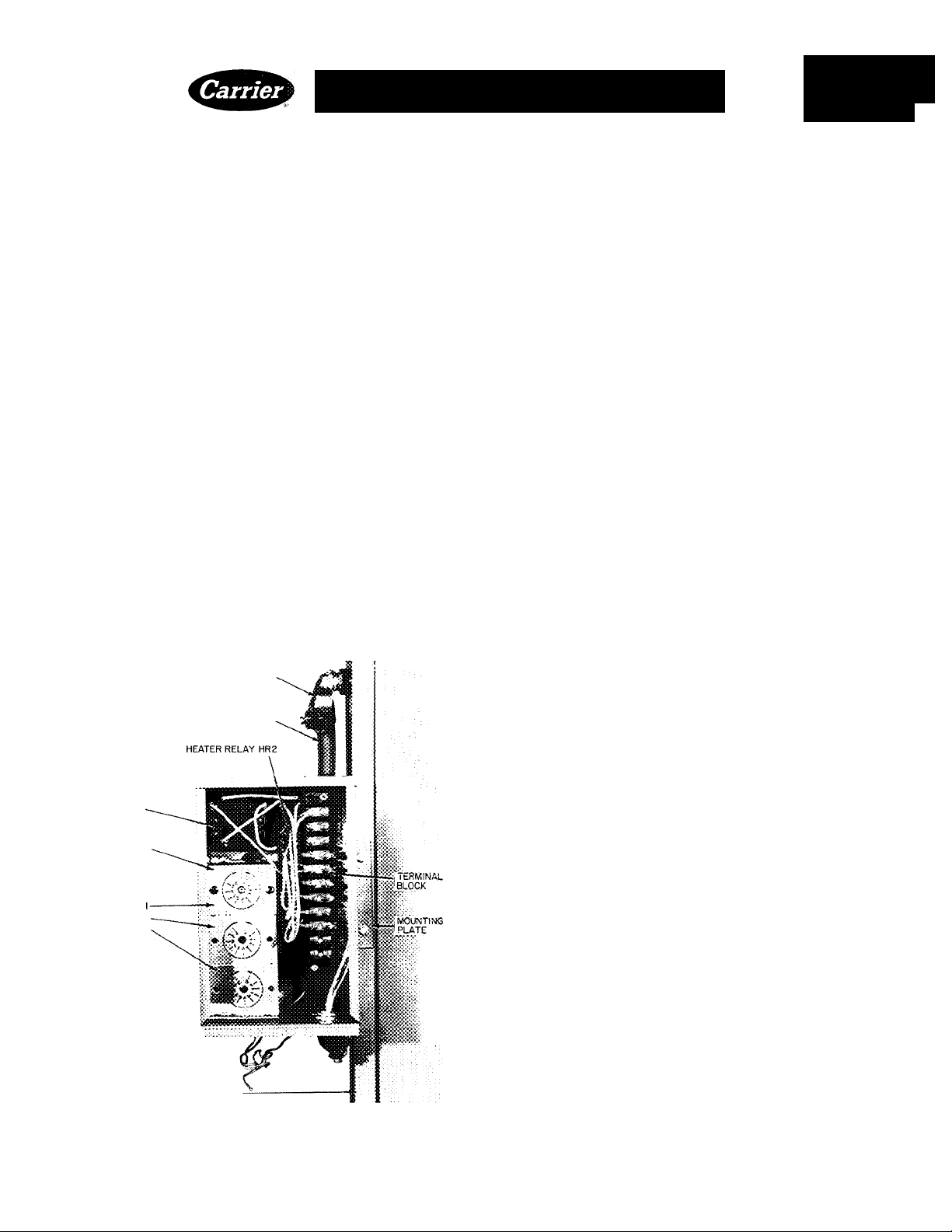
1 Emergency Heat Terminal Block HY84FC117
1 Heater Relay (HR-1) HN61KK324
1 Heater Relay (HR-2) HN61KL016
1 Outdoor Air Thermostat (OAT.) HH22QA040
One or 2 additional outdoor thermostats may be
installed if required. Mount additional thermostat(s) in the control box as follows:
f. Remove control box cover.
2. Remove thermostat barrier (See Fig. 1).
FIELD CONTROL WIRING
SEALTITE CONDUIT
THERMOSTAT
BARRIER
OUTDOOR AIR
THERMOSTAT
LOCATION
NO
N02
N0 3
EMERGENCY HEAT
CONTROL BOX
____
CAPILLARIES
COMPRESSOR ACCESS
PANEL CORNER POST
Fig. 1 — Accessory Emergency Heat
Control Box Installation
3. Attach additional thermostat(s) to barrier using
field supplied 8-32 machine screws. Using field
supplied wire, connect the additional thermostat(s) to control box components as shown in
Fig. 2.
4. Replace barrier in control box.
5. Using screws taped to control box mounting
plate, secure control box to compressor access
panel corner post (see Fig. 1 and 3).
6. Using field supplied wire, connect the control
box to the conditioned space and base unit. For
50RQ,PQ006 units, wire in accordance with
Fig. 4, for 50RQ,PQ008/010 units, wire in
accordance with Fig. 5. Enclose wiring in
field-supplied conduit as required. Conduit to
be “Sealtite” or equal. There are 2 conduit
connection holes in bottom of control box.
Use 1 hole for wiring entering the control box
from the conditioned space and the other for
all wiring leaving the control box to the base
unit. (Note: A portion of the wiring is routed in
1 hole and directly out the other and is not
connected to the control box terminal block).
See Fig. 1 and Fig. 3.
Outdoor Thermostat(s) — A 3-ft capillary tube
connects the thermostat bulb to the thermostat
body. If space is available inside of control box and
control box is not in direct sunlight, capillary tubes
may be left in box. For best performance, locate
capillary tube(s) outside of box. Pull 1- to 2-in. of
capillary tubing thru the rubber grommet in
bottom of control box, neatly bend tubing and
locate under control box. Bulb(s) must not be in
direct sunlight. Bulb(s) must be in a shaded
location to sense true outdoor temperature. Shield
bulb(s) with suitable field supplied material if
required. An outdoor thermostat is required for
each stage of heat. This instruction covers 2 stages
of heat for the 50RQ,PQ units. Three stages of
heat are available for 39 Kw heat only. If 3 stages
of heat are required, contact the Carrier represent
ative for appropriate installation instructions.
Refer to building heat load calculations for
correct thermostat setting
© Carrier Corporation 1977
Form 50RQ-6SI
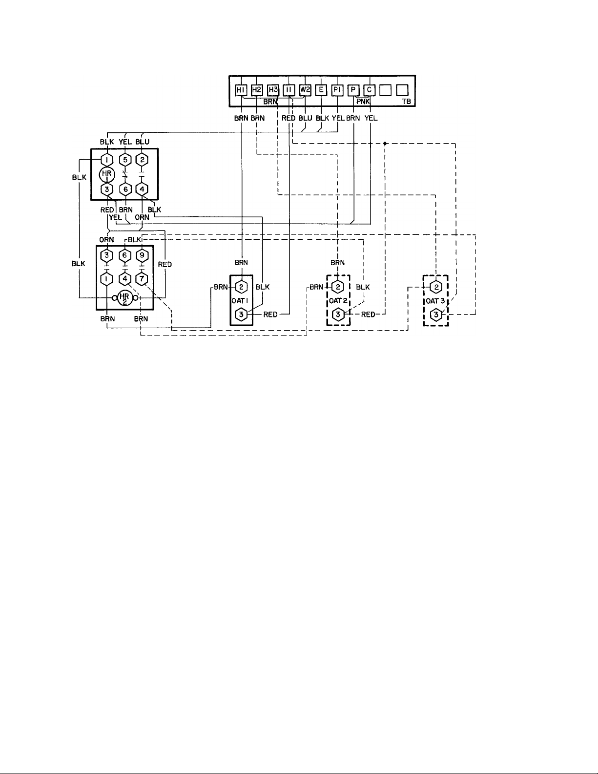
EMERGENCY HEAT CONTROL BOX
FOR CONTROL BOX CONNECTIONS
TO THERMOSTAT AND BASE
UNIT REFER TO FIG. 4 AND 5.
^ iC
HR — Heater Relay
OAT — Outdoor Air Thermostat
TB - Ter minal Block
_______
Factory Wiring
_______
Field Wiring
Fig. 2 — Schematic Diagram, Accessory Emergency Heat Control Box, 50RQ,PQ
Outdoor Thermostat Setting — Set the outdoor
□ Terminal Block Connections (Marked)
Component Connections (Marked)
O Component Connections (Unmarked)
Field Splice
thermostat temperature indicating dial for each
individual installation. If more than 1 thermostat is
used, set additional thermostats in sequence to
allow additional strip heaters to come on as the
outdoor temperature lowers. Before heaters can
come on (except during defrost cycle):
1. The outdoor temperature must be below the
setting of the outdoor thermostat.
2. The room temperature must be 2 F below the
setting of the room thermostat so that the
contacts on the second step of the thermostat
can close. An outdoor thermostat setting that is
higher than necessary results in excess operating
costs; too low a setting prevents heaters from
coming on when they are needed.
• On completion of outdoor thermostat setting,
replace cover on the control box.
Emergency Heat Operation — If a safety device is
tripped, the compressor locks out thru the oper
ation of the Signal-LOC^ivi circuit. When this
occurs, the indicator light comes on at the room
thermostat.
The switch at the room thermostat can then be
moved to EMERGENCY HEAT, bypassing the
compressor and the outdoor thermostat(s) The
second stage of heating at the room thermostat
then activates the resistance heaters to satisfy space
requirements — regardless of outdoor temperature.
If desired, the compressor can be manually locked
out by setting the thermostat to EMERGENCY
HEAT. Under either condition — a tripped safety
device or manual lockout, the indicator light at the
thermostat is illuminated.
 Loading...