

Carrier 50JZ060300, 50JZ048300, 50JZ042300, 50JZ036310, 50JZ036300 Owner’s Manual
...
50JZ
HF-JkTUNG& COOLING
\isitx__ _.carrier.com
A Guide To Operating and Maintaining Your
SingMe-Package EMectric Heat Pump Unit
NOTE TO INSTALLER
This manual should be left v,ith the equipment owner.
Do not store or use gasoline or other flammable wtpors and
liquids in the vicinity of this or any other appliance. Failure to
follow this warning could result in fire, serious injury, or
death.
Do not use this unit if any part has been under water
Immediately call a qualified ser'vice technician to inspect the
unit and to replace any part of the control system which has
been under water Failure to _bllow this warning could result
in electrical shock, fire, serious injury, or death.
SingMe-Package EMectric Heat Pump Unit
with Puron® (R-410A) Refrigerant
Befbre performing recommended maintenance, be sure the
main power switch to unit is turned off Electric shock could
cause serious i11iury or death.
TO START UNIT
1, Turn on the electrical power supply to unit,
2, Select temperature and set SYSTEM switch or MODE control
to desired mode,
TO SHUT UNIT OFF
If" unit is being shut down because of a malfunction, call your
dealer as soon as possible
1. Set system SWITCH or MODE control to OFF.
2. Turn off the electrical power supply to unit.
OPERATING YOUR NEAT PUMP UNIT
The operation of your heat pump system is controlled by d-m
indoor thermostat You simply adjust d_e thermostat and it
maintains the indoor temperature at the level you select. Most
thermostats for heat pump systems have 3 controls: a temperature
control selector, a FAN control, and a SYSTEM or MODE control
Refer to your daem_ostat owner's manual _br more information.
Step l--Cooling Mode
With the SYSTEM oi" MODE control set to COOL, your heat
pump will run in cooling mode until the indoor temperature is
lowered to the level you have selected. On exhemely hot days,
your heat pump will run for longer periods at a time and have
shorter "ofF' periods than on moderate days.
Step 2--Heating Node
With the SYSTEM oi" MODE control ofyonr indoor them_ostat set
to HEAT, your heat pump will run in heating mode until room
temperature is raised to ff*e level you have selected. Of course,
your heat pump will have to operate _br longer periods to maintain
a comfbrtable environment on cooler days and nights than on
moderate ones
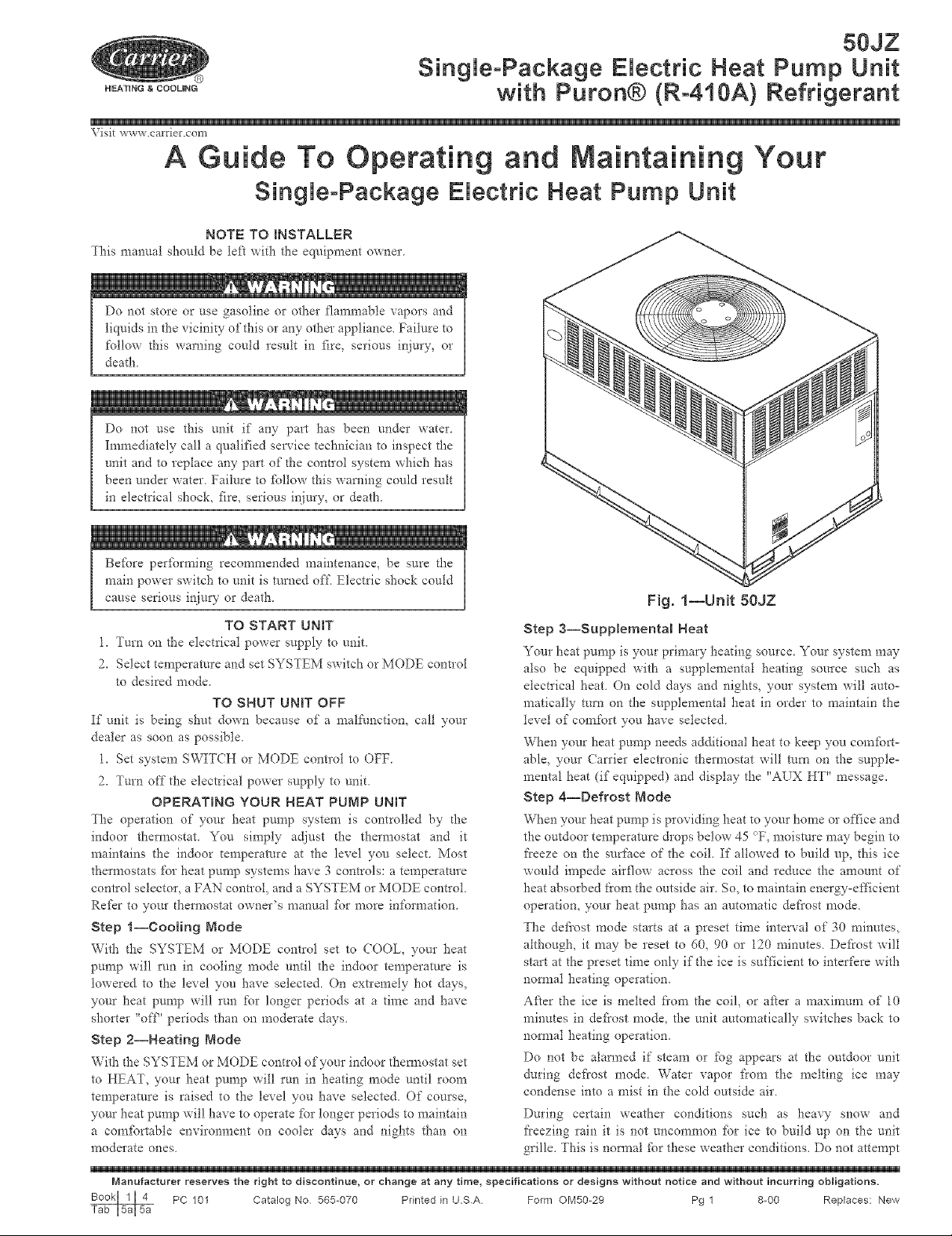
Fig. 1--Unit 80JZ
Step 3--Supplemental Heat
Your heat pump is your primary heating source. Your system may
also be equipped with a supplemental heating source such as
electrical heat. On cold days and nights, your system will auto-
matically mm on the supplemental heat in order to maintain the
level of comfort you have selected.
When your heat pump needs additional heat to keep you comt_rt-
able, your Carrier electronic thermostat will mrn on the supple-
mental heat (if equipped) and display the "AUX HT" message.
Step 4--Defrost Mode
When your heat pump is providing heat to your home o1"office and
the outdoor temperature drops below 45 OF, moistme may begin to
fi'eeze on d-_e surface of the coil. If allowed to build up, this ice
would impede airflow across the coil and reduce the amount of
heat absorbed from the outside air. So, to maintain energy-efficient
operation, your heat pump has an automatic defrost mode.
The defiost mode starts at a preset time interval of 30 minutes,
although, it may be reset to 60, 90 or 120 minutes. Defrost will
start at the preset time only if the ice is sufficient to interfere with
nomml heating operation.
After d_e ice is inched fi'om the coil, or afier a maximum of 10
minutes in defrost mode, the unit automatically switches back to
nomml heating operation.
Do not be alarmed if steam or fog appears at the outdoor unit
during defrost mode. Water vapor fiom the melting ice may
condense into a mist in the cold outside air.
During certain weather conditions such as heavy snow and
freezing rain it is not uncommon fbr ice to build up on the unit
grille. This is nomml _br these weather conditions. Do not attempt
Manufacturer reserves the right to discontinue, or change at any time, specifications or designs without notice and without incurring obligations.
PC 101 Catalog No 565-070 Printed in U.SA Form OM50-29 Pg 1 8-00 Replaces: New
to remove the ice fi'om the unit grille. This condition will not affect
the proper function of the uriit and will clear within a few days.
Step g--Emergency Heat Mode
This allows your supplemental heating source to keep your home
or office wam_ until your heat pump can be sela'iced.
mNPORTANT FACTS
To better protect your investment and to eliminate nnnecessaD"
service calls, fim_iliarize yourself with the following ii_cts:
During heating, increasing the tlaermostat setting more than 2c_may
cause the supplemental heaters to be turned on fbr a short period
of time to satisfy the thermostat. Needles use of the supplementary
heat reduces potential energy savings.
Ice or f?ost will tend to form on the coil during the winter heating
operation. Your heat pump is designed to automatically melt the
ice. When in this defrost cycle, it is not_nai for steam or fog to rise
fi'om the outdoor unit. Do not be alarmed!
ROUTINE NAINTENANCE
All routine maintenance should be handled by skilled, experiericed
personnel. Your dealer can help you establish a standard proceo
dure.
For your sat'cty, keep the unit area clear and fi'ee of combustible
materials, gasoline, and other flammable liquids and vapors.
To assure proper functioning of the unit, flow of condenser air
must not be obstr_/cted from reaching the unit. Clearance from the
top of the unit is 48 in. Clearance of at least 36 in. is required on
sides except the power entry side (42 in. clearance) and the duct
side (12 in. rain clearance).
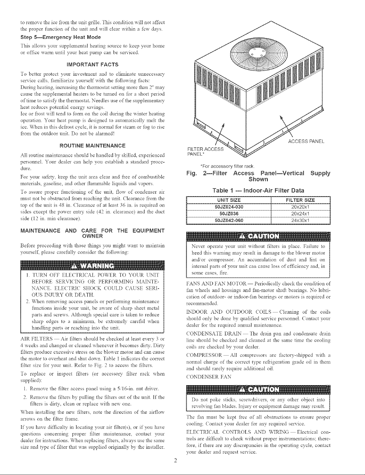
FILTER ACCESS
PANEL*
*For accessory filter rack.
Fig.
2--FHter Access Panel--VerticN Supply
Shown
Table 1 -- Indoor-Air Fitter Data
UNIT SIZE FILTER SIZE
50JZ024-030 20x20x1
50JZ036 20x24xl
50JZ042o060 24x30x1
ACCESS PANEL
NA_NTENANCE AND CARE FOR THE EQUmPNENT
OWNER
Befbre proceeding with those things yon might want to maintain
yourself; please carefldly consider the following:
1. TURN OFF ELE(TRICAL POWER TO YOUR UNIT
BEFORE SERVI(ING OR PERFORMING MAINTE-
NAN(E. ELE(TRIC SHO(K COULD (AUSE SERI-
OUS INJURY OR DEATH.
2. When removing access panels or perfbm_ing maintenance
Nnctions inside your unit, be aware of sharp sheet metal
parts and screws. Although special care is taken to reduce
sharp edges to a minimum, be extremely careNl when
handling parts or reaching into the unit.
AIR FILTERS Air filters should be checked at least every 3 or
4 weeks arid changed or cleaned whenever it becomes dirty. Dirty
filters produce excessive stress on the blower motor and can cause
the motor to overheat and shut down. Table 1 indicates the correct
filter size fbr your unit Refer to Fig 2 to access the filters
To replace or inspect filters (or accessory- filter rack when
supplied):
1. Remove the filter access panel using a 5/16-in. nut driver.
2. Remove _he filters by pulling the filters out of the unit. If the
filters is dirty, clean or replace with new one.
When installing the new filters, note the direction of the airflow
arrows on the filter frame.
If you have difficulty" in locating your air filter(s), or if you have
questions concerning proper filter maintenance, contact your
dealer for instructions. When replacing filters, always use the same
size and type of filter that was supplied originally by the installer.
Never operate your unit without filters in place. Failure to
heed this warning may result in damage to the blower motor
and/or compressor An accumulation of dust arid lint on
internal parts of your unit can cause loss of efficiency and, in
SOITIe cases_ fire
FANS AND FAN MOTOR Periodically check d_e condition of
fan wheels and housings and fan-motor shaft bearings No lubrio
cation of outdoor- or indooroflm bearings or motors is required or
recommended
INDOOR AND OUTDOOR COILS Cleaning of the coils
should only be done by qualified service personnel. (ontact your
dealer fbr the required annual maintenance.
CONDENSATE DRAIN The drain pan and condensate &ain
line should be checked and cleaned at the same time the cooling
coils are checked by your dealer.
COMPRESSOR All compressors are fi_ctoryoshipped with a
normal charge of the correct type refi'igeration grade oil in them
and should rarely require additional oil.
CONDENSER FAN
Do not poke sticks, screwdrivers, or any other object into
revolving fan blades Injury or equipment damage may result
The fire mttst be kept flee of all obstructions to ensure proper
cooling Contact your dealer for any required service.
ELECTRICAL (ONTROLS AND WIRING Electrical con°
trois are difticult to check without proper instrumentations; there-
fore, if there are any discrepancies in the operating cycle, contact
your dealer and request sela'ice.
 Loading...