

Page 1
Number One
AirConditioninq
Maker
^^2 Divisiort of
Carrier Corporation
Carrier Parkway • Syracuse NY 13221
i
-
Single-Package
Water-Source Heat Pumps
SAFETY CONSIDERATIONS...................................1
INSTALLATION........................................................1-5
Step 1 — Check Equipment and
Jobsite .......................................................................1
• UNPACKAGE UNIT
• INSPECT EQUIPMENT
• COMPLETE OR CONSIDER THESE
SYSTEM REQUIREMENTS
Step 2 — Connect Supply Ductwork
Step 3 — Make Piping Connections
• CONNECT WATER SUPPLY AND
RETURN LINES
• INSTALL BALANCING VALVES
.....................
......................
Page
2
3
INDEX
Page
• MAKE CONDENSATE DRAIN
LINE CONNECTION
Step 4 — Make Electrical Connections... 4
• INSTALL A BRANCH CIRCUIT
DISCONNECT PER NEC
• BRING POWER LEADS INTO UNIT
• CONNECT GROUND LEAD TO
GROUND LUG IN SPLICE BOX
• SET FAN MOTOR SPEED
• CONNECT CONTROL POWER WIRING
START-UP
SERVICE....................................................................7
..................................................................
6
SAFETY CONSIDERATIONS
Installation and servicing of air conditioning
equipment can be hazardous due to system pressure
and electrical components. Only trained and quali
fied service personnel should install, repair or
service air conditioning equipment.
Untrained personnel can perform basic mainten
ance functions of cleaning coils and cleaning and
replacing filters. All other operations should be
performed by trained service personnel. When
working on air conditioning equipment, observe
precautions in the literature, tags and labels
attached to the unit and other safety precautions
that may apply.
Follow all safety codes. Wear safety glasses and*,
work gloves. Use quenching cloth for brazing
operations. Have fire extinguishers available for all
brazing operations.
WARNING: Before performing service or
maintenance operaiions on system, turn off
main pow'er switch to indoor unit and outdoor
unit. Electrical shock could cause personal
injury.
INSTALLATION
Step 1 — Check Equipment and Jobsite
UNPACKAGE UNIT — Move to final location.
INSPECT EQUIPMENT — File claim with ship
ping company if shipment is damaged or incomplete.
COMPLETE OR CONSIDER THESE SYSTEM
REQUIREMENTS before installation:
a.
Consult local building codes and National Elec
trical Code (NEC) for special installation
requirements.
Consider type of water source. Ensure there is an
adequate supply of water at temperature of 60 F
to 90 F with minimum pressure of 20 psig.
c.
Provide sufficient space for water piping, con
densate drain, wiring and servicing unit. See
Fig. 1. (Units installed in confined areas may
have to be removed for major servicing such
as compressor or fan motor replacement.)
d.
Provide a minimum 6-in. clearance between
return air filter and adjacent wall.
e.
Mount unit on floor or solid platform. (The
50HQ units can be suspended from ceiling.
See “f’ below.) To reduce sound transmission,
especially when unit is located in a closet or
utility room having louvered doors, the follow
ing acoustical treatment is recommended:
place an isolation pad under unit. Pad must be
same size as unit base. Construct a 1-in. fiberglass
sound shield in front of unit.
© Carrier Corporation 1981
Form 50HQ.VQ-2SI
Page 2
f. 50HQ units include a'sus'pehsion package for
ceiling installation. To attach hanging brackets,
install 4 bolts (5 /16 - 18-3/8 in. Ig) thru bracket
into the 4 weld nuts located on bottom of unit.
Insert the threaded rod thru rubber grommet,
located in hanging bracket, and attach with flat
washer and double nut. See Fig. 3.
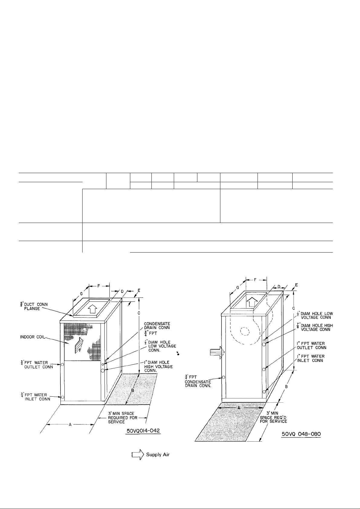
Step 2 — Connect Supply Ductwork — Supply
air duct flange is shipped inside unit. Remove flange
from shipping location and install on unit supply
air opening. Connect supply air ductwork to unit
supply air duct connection flange. Refer to Fig. 1
and 2 and Table 1 and 2 for connection size and
location. If necessary, refer to Carrier System
Design Manual, Part 2, for system air duct design.
^ Table 1 — Installation Data — 50VQ (See Fig. 1.)
MODEL 50VQ
OPER WT (lb)
DIMENSIONS (ft-in.)
SUPPLY DUCT CONN.
(ft-in.) F 0-9-7/16
FILTER (1)
Size (in.)
014
_5
A
B
C
D
E
G 1-1-3/8
018
240“^
022
260 270
027
1-9-3/16
1-9-3/16
3-2-5/16
0-5-7/8
0-1-3/16
21 X 21
When E-e'dignihg and installing ductwork, consider
tfie following:
a. Size duct for 350 to 450 cfm per ton of cooling
capacity.
b. Avoid abrupt duct size increases and reductions.
c. Use flexible connectors between ductwork and
unit to prevent transmission of vibration.
d. Ducts passing thru an unconditioned space must
be insulated and covered with vapor barrier in
accordance with the latest issue of SMACNA
(Sheet Metal and Air Conditioning Contractor’s
National Association) and NESCA (National
Environmental Systems Contractor’s Associa
tion) minimum installation standards for resi
dential heating and air conditioning systems.
033
290
Replaceable Media
042
320 320
048 060
0-6-13/16
0-10-1/2 1-1-1/16 1-0
350
2-5-3/8
2-3
4-0
0-8
0-5-1/2
1-4
38 X 22
080
380
0-6-1/16
Return Air
Fig. 1 — Dimensions and Connections — 50VQ
Page 3
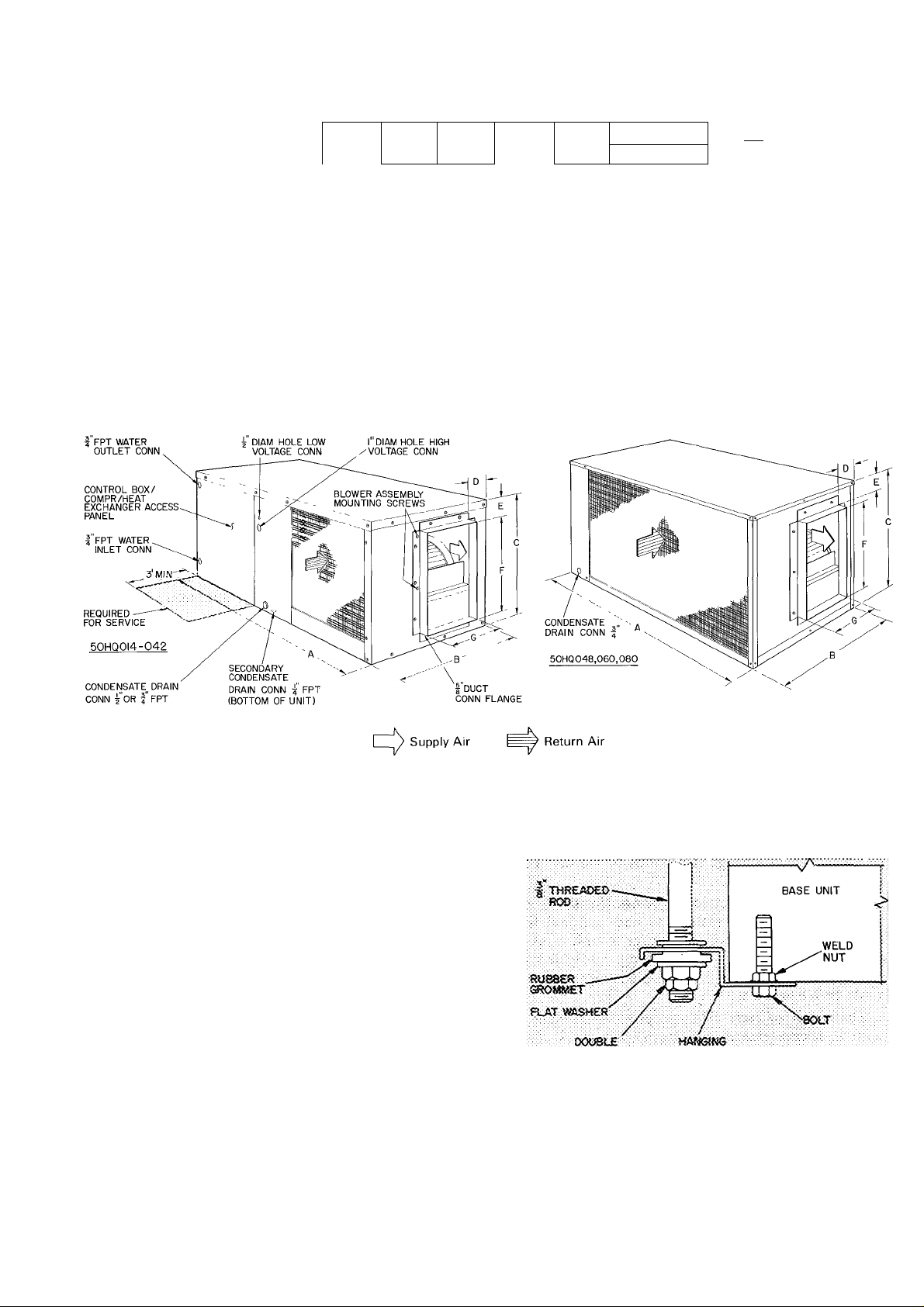
Table 2'— Installation Data — 50HQ (See Fig. 2.)
I
MODEL 50HQ
OPERwfob)
"dimensions (ft-in.)
_E
"supply duct conn.
(ft-in.) F
_ _ G
ACCESSORY FILTER (1)
Size (in.)
014
220
A
B
C
D
018 022 027 033
195 210 220
3-10-1/2
1-10-5/16
1- 5-15/16
0- 3-7/8
11/16
1- 1-3/8
0- 9^-7/16
17 x23
230
042 048
250 300
0- 3-7/8
Replaceable Media
060
325
4- 0
1-11
2- 0
0-2-9/16
0-3-3/16
1-7-7/8
37 X 23
080
360
0-3-1/16
1-0
Fig. 2 — Dimensions and Connections — 50HQ
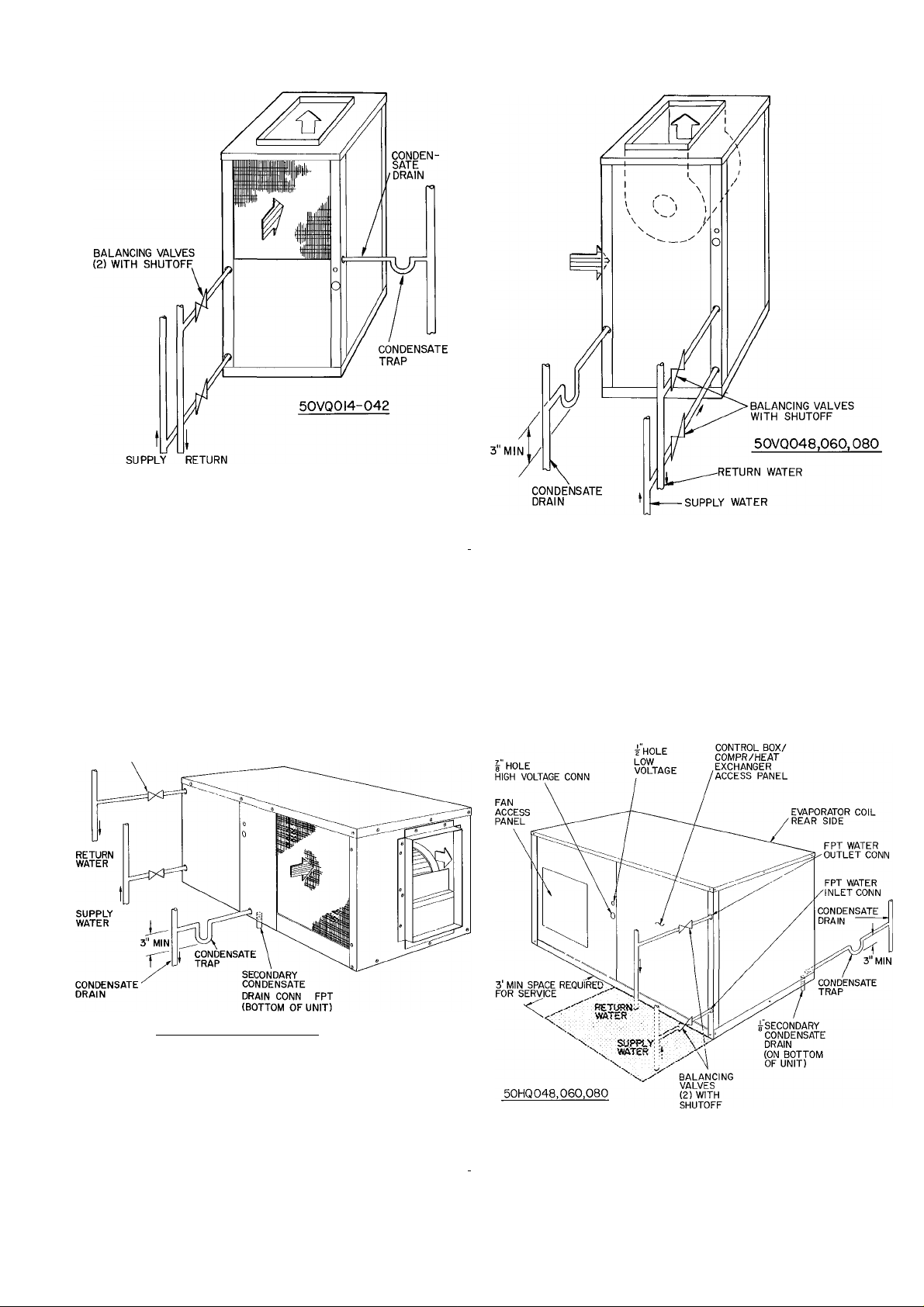
Step 3 — Make Piping Connections
CONNECT WATER SUPPLY AND RETURN
LINES to water inlet and outlet pipe connections
shown in Fig. 4 and 5. Use flexible hose for water
line to reduce possible vibration and improve unit
serviceability. Make sure hoses or pipes are suitable
for system water pressure and sized for proper
flow rate.
CAUTION; improper heat exchanger water
flow due to piping, valving or improper pump
operation is hazardous to units.
For water flow and temperature data refer to
Start-Up section, page 6.
CAUTION: Galvanized pipe or fittings are not
recommended for use with these units due to
possible electrolysis.
nut
BRACKET
Fig. 3 — Suspension Kit
Installation — 50HQ
Page 4
Table 3 — Electrical Data
UNIT MODEL
50HQ,VQ
014
018
022
027
033
042
048
060
033
042
048
060
080
033
042 36 5
048
060 49 0 104
080 69 0 11 4
FLA — Full Load Amps
LRA — Locked Rotor Amps
RLA — Rated Load Amps
V/PH/HZ
208-230/1/60 253
208-230/3/60 253 187 80 0
460/3/60 508
OPERATING
VOLTAGE
Max
Min LRA RLA
197
187
414
INSTALL BALANCING VALVES (with shutofO
in water supply and return lines for water flow
adjustment and a means of water shutoff, if neces
sary, when servicing unit. When multiple units are
connected in parallel, valves permit removal of one
unit without interrupting water flow to other
units.
MAKE CONDENSATE DRAIN LINE CON
NECTION to female pipe connection provided on
unit. Fig. 4 and 5. Install a trap in condensate line as
close as possible to unit. Trap must be at least 3 in.
deep and not higher than the bottom of unit con
densate drain opening. Pitch condensate line to
open drain or sump. Insulate a condensate drain line
located above a living area.
50HQ Units Only — If a secondary drain is re
quired, remove plastic cap from secondary drain
connection, located in bottom of unit, and connect
drain so that discharge is obvious to maintenance
personnel.
Step 4 — Make Electrical Connections — Field
wiring must comply with local and national fire,
safety and electrical codes. Voltage to unit must be
within the operating voltage range indicated on
nameplate or in Table 3. On 3-phase units, phases
must be balanced within 2%.
Operation of unit on improper line voltage or
with excessive phase imbalance constitutes abuse
and is not covered by Carrier Warranty.
INSTALL A BRANCH CIRCUIT DISCONNECT
PER NEC of adequate size to handle unit starting
current. Locate disconnect within sight of and
readily accessible from the unit, per Section 440-14
of National Electrical Code (NEC).
BRING POWER LEADS INTO UNIT — Extend
leads from disconnect per NEC thru hole provided
(Fig. 1 and 2) into line wiring splice box. Fig. 6.
COMPRESSOR
37 5
53 0
65 0 13 3
66 0
88 0 23 3
100 0
94 0 23 9
150 0 35,3
87 0 13 8 2 5
100 0
136 0 20 6
137 0 20 7
30 0 60
35 0 8 2
9 6
134
16 2
27 7
18 5
16 8 3 9 24 9
6.9
FAN
FLA
7 12.7
9
1.5 18 1 30
1 7 22 0 35
2 5 31.6
3 2
34 33 4 60
4.5
3 2
4 5
6 2 32 1
1 1
1 6 10 2
20 12 3
2 6
31 17 4
MINIMUM
CIRCUIT
AMPS AMPS
17.7
37 8
48.6
19 8 30
26 3
30 6
8 9
15 3 25
MAXIMUM
FUSE
CONNECT GROUND LEAD TO GROUND
LUG IN SPLICE BOX for safety. Connect power
wiring. See Fig. 6. Splice line power leads to yellow
and black pigtails on single-phase units or yellow
pigtails on 3-phase units. Use wire nuts. Tape each
connection.
Unit transformer on 208-230-volt units is factory
wired for 230/24-volt operation. For 208/24-volt
operation, remove black (230-v) transformer lead
from unit contactor and connect red (208-v) lead to
contactor. Cap unused transformer lead.
SET FAN MOTOR SPEED — Set fan motor for
high-, medium- or low-speed operation as follows:
1. Remove unit fan section access panel.
2. Locate Molex fan speed selector block on fan
housing. Fig. 7. Selector block receptacle 1 is
high fan speed, receptacle 2 is medium fan speed
and receptacle 3 is low fan speed. Yellow and
black fan motor power leads from control box
are connected to selector block receptacle C and
1. Yellow lead is common, black lead is speed-
change lead.
3. To change fan motor speed, remove black lead
from selector block receptacle and plug it into
desired receptacle. Receptacle 4 is not used.
CAUTION: For proper utiit operation, set unit
fan motor speed for air quantity witbin range
shown in Table 4.
Set Fan Motor Speed on 460-Volt Units — Twospeed fan motor is factory wired for high-speed oper
ation. (Yellow and black power leads from control
box are connected to the yellow and black fan motor
leads.) Change fan motor to low speed by wiring as
follows:
1. Splice the violet and black fan motor leads
together.
20
30
50
60
60
40
40
45
45
15
15
15
25
L
Page 5
i
WATER WATER
I Supply Air
‘ Return Air
Fig. 4 — Water Piping — 50VQ
BALANCING VALVES
(2) WITH SHUTOFF
50HQ0I4,018,022,027, 033,042
pply Air
I Return Air
Fig. 5 — Water Piping — 50HQ
5
Page 6

2. Splice yellow and black power leads from eontrol
box to yellow and red motor leads. (Yellow-toyellow and black-to-red.)
CONNECT CONTROL POWER WIRING (24-v)
— Power leads are brought thru 1/2-in. hole pro
vided in unit, Fig. 1 and 2. Extend leads to control
wiring terminal board located on top of control box,
Fig. 7. Connect leads to terminal board as shown
in Fig. 6.
Use Carrier-specified room thermostat and sub
base for proper unit operation. Be sure that field-
installed jumper wire is connected between subbase
terminals W and Y. Set thermostat heat anticipator
at 1.0 amp for 1-phase units and 0.50 amp for
3-phase units.
FAN SPEED
SELECTOR BLOCK
(MOLEX PLUG)
COMPRESSOR
Fig. 7 — Typical Component Arrangement
(50HQ014-042 Shown)
—^YEL —
-TUyel —
_iT^YEL —
GROUND
—œilug
50HQ.VQ
HEAT PUMP
CONTROL BOX
1-PHASE
CONN. TO
DISCON NECTPER NEC
GROUND
LEAD
—^YEL —
—^BLK —
,__.GROUND
—TSlLUG
50HQ.VQ
HEAT PUMP
CONTROL BOX
I-PHASE
3-PHASE
CONN. TO
DISCONNECTPER NEC
—
GROUND
LEAD
Fig. 6 — Line Power Connections
START-UP
Water Flow and Temperature Data
1. Consider design water flow rates for efficient
operation. See Table 4 for permissible water flow
range.
2. Ensure that water temperature entering unit is
between 60 F minimum and 90 F maximum. If
water temperature below 60 F must be used,
insulate supply line and install a secondary drain
pan under the unit to remove condensate from
heat exchanger and internal plumbing.
CAUTION: Water temperature outside
specified temperature rartge may cause
damage to mût Do not jumper low temperar
ture switch in order to use ethytene giycoi.
3. Ensure that supply water is clean and air is
purged from system. Air in supply water causes
scaling in heat exchanger. Foreign material in
water and/or excessive velocity of water can
cause damage to tubing.
To Start Unit — Ensure that air filter is in place on
unit filter flanges provided. Do not operate unit
without filter in place. Adjust the thermostat as
follows;
1. Set selector switch at OFF.
2. Turn on main disconnect switch to unit.
3. Set fan switch as desired (ON or AUTO.).
4. Set thermostat dial at desired temperature.
5. Set selector switch at HEAT or COOL.
Check system refrigerant charge. See Service,
Refrigerant Charging on page 7.
Unit Single-Phase Compressors Equipped
With a Compressor Start Thermistor (PTC De
— When supply voltage is within limits indi
vice)
cated on nameplate and compressor will not start,
check the thermistor with an ohmmeter.
If the PTC is good, and the compressor does not
start, disconnect the PTC from the starting circuit
and give unit a temporary capacitanee boost. Refer
to Carrier Standard Service Techniques Manual,
Chapter 2, for details on capacitance boost pro
cedure. If unit does not start with capacitance boost,
compressor may be defective. If unit does start,
check starting capability with PTC assistance. If
questionable, remove PTC, add start capacitor and
start relay per start kit installation instructions.
WARNING: Capadtance boost or iastallatioa
of start capacitor and start relay should be per
formed by trained personnel. Improper procedure could cause personal injurj' or equipment
damage.
Unit Controls and Safety Devices
HIGH-PRESSURE RELIEF VALVE (except
50HQ,VQ0I4) is located in compressor. Relief valve
opens at a pressure differential of approximately
550 psi between suction (low side) and discharge
(high side) to allow pressure equalization.
CURRENT AND TEMPERATURE SENSITIVE
OVERLOAD (linebreak) — Internal on all com
pressors except on 50HQ,VQ014 which has external
shell mounted overload. Overload resets auto
matically when internal compressor motor tempera
ture drops to a safe level (overloads may require up
to 45 minutes to reset). When an internal overload is
suspected of being open, eheck by using an ohm-
Page 7

I
meter or continuity tester. If necessary, refer to
Carrier Standard Service Techniques Manual,
Chapter 2, for complete instructions.
HIGH-PRESSURE SWITCH closes and shuts
compressor off if discharge pressure rises above 395
psig. Switch opens at 295 psig.
FREEZE-UP PROTECTION — Two controls are
used to prevent unit from operating if water
approaches freezing temperature:
1. Low water temperature cutout (LWTC) shuts
unit off and energizes lockout relay if water
temperature reaches 37 F.
2. Lockout relay locks itself in energized position
and prevents unit from starting.
The unit can be restored to heating operation if
the water temperature rises to 42 F, where the
LWTC will reset, and if the thermostat circuit is
interrupted either by lowering the thermostat
setting or by moving system switch to OFF or
COOL. Thermostat may then be readjusted to
normal set point.
HEAT PUMP CIRCUITS, shown in Fig. 8, are
refrigerant and water flow diagrams for heating
and cooling cycles.
SERVICE
Refrigerant Charging — Unit refrigerant system
is factory charged. When recharging is necessary
during heating or cooling season, weigh in total
charge indicated in Table 4. Remove any refrigerant
remaining in system before recharging. If system has
lost complete charge, evacuate system to 500
microns (29.7 in. vacuum) before recharging.
Service port connections are provided on high and
low sides of refrigerant system for evacuation and
charging. (See Fig. 8 for service port location.)
Dial-a-charge charging cylinder is an accurate
device used to recharge systems by weight. These
cylinders are available at refrigeration supply firms.
To check and/or adjust refrigerant charge during
cooling season, use correct Cooling Cycle Charging
^ Chart (Fig. 9, 11, 13, 15,17,19,21,22,23) or Carrier
Chargemaster® charging device (Carrier Part No.
38GC680004). Charging charts or Chargemaster
may also be used as alternate methods of recharging
system. Charging methods are described below.
To cheek system operation during heating cycle,
use correct Heating Cycle Operation Check Chart
(Fig. 10, 12, 14, 16, 18, 20). These charts indicate
whether a correct relationship exists between unit
operating pressures and water temperature leaving
heat exchanger. If pressure and water temperature
lines do not intersect on chart, the system refrigerant
charge may not be correct or other system abnor
malities may exist. Do not use Operation Check
Charts to adjust refrigerant charge. Weigh charge
into system.
COOLING CYCLE HEATING CYCLE
Fig. 8 — Refrigerant and Water Flow Diagrams — 50HQ,VQ
Page 8

Table 4 — Service Data
UNIT 50HQ.VQ
R-22 CHG (Ib-oz)»
Refrig Control
FAN
Diameter (in. Nom) 10
Width (in. Nom)
Range Cfm 400-600 500-700 600-800 750-1000 950-1200 1225-1575
Motor Hp 1/8 1/8 1/6 1/6 1/4
Motor Rpm
(3-speed)
HEAT EXCHANGER
WATER FLOW RATE
(Gpm)
‘Factory refrigerant charge
014 018
1-8 1-13
7
2 5-5 3-6 4-8 4 5-9
10
7 7 7 7 7 8
022
2-2 2-6
10 10
027
033 042 048 060
2-6 2-14 4-3
Capillary Tube
Centrifugal — Direct Drive
10
1075 Nominal
5-10
COOLING CYCLE CHARGING CHART
METHOD
1. Operate unit a minimum of 10 minutes before
checking charge, and after each charge
adjustment.
2. Measure suction pressure by attaching a gage to
unit suction service port (Schrader Fitting).
3. Measure discharge pressure by attaching a gage
to unit discharge service port (Schrader Fitting).
4. Using a sling psychrometer, measure wet-bulb
temperature of air entering unit.
5. Refer to correct Charging Chart. Locate on
curves where unit discharge pressure line and
indoor air wet-bulb temperature line intersect.
6. From intersect point, project horizontally left to
ISO 200 250 300
COMPRESSOR DISCHARGE PRESSURE @ SERVICE PORT (PSIG)
chart suction pressure line. Compare chart
suction pressure to unit suction pressure (step 2).
7. If unit suction pressure is lower than chart pres
Fig. 10 — Heating Cycle Operation
Check Chart (R-22) — 50HQ.VQ014
sure, add refrigerant to unit until chart pressure
is reached. If unit suction pressure is higher than
chart pressure, remove refrigerant until chart
pressure is reached.
11
1/3
6-12 8-16
10 10
1400-1800 1750-2250
1/2 3/4
5-3 6-8
10
2300-3000
11-21
080
12
9
1
1000
14-28
ISO 200 250 300
COMPRESSOR DISCHARGE PRESSURE ® SERVICE PORT(PSIG)
Fig. 9 — Cooling Cycle Charging Chart
(R-22) — 50HQ,VQ014
COMPRESSOR DISCHARGE PRESSURE @ SERVICE PORT (PSIG)
Fig. 11 — Cooling Cycle Charging Chart
(R-22) — 50HQ.VQ018
Page 9

Fig. 12 — Heating Cycle Operation
Check Chart (R-22) — 50HQ,VQ018
Fig. 15 — Cooling Cycle Charging Chart
(R-22) — 50HQ,VQ027
COMPRESSOR DISCHARGE PRESSURE ® SERVICE PORT(PSIG)
Fig. 13 — Cooling Cycle Charging Chart
(R-22) — 50HQ,VQ022
Fig. 14 — Heating Cycle Operation
Check Chart (R-22) — 50HQ,VQ022
Fig. 16 — Heating Cycle Operation
Check Chart (R-22) — 50HQ,VQ027
COMPRESSOR DISCHARGE PRESSURE® SERVICE PORT (PSIG)
Fig. 17 — Cooling Cycle Charging Chart
(R-22) — 50HQ.VQ033
Page 10

COMPRESSOR DISCHARGE PRESSURE@SERVICE PORT(PSIG)
a
2 no
ISO 200 250 300
COMPRESSOR DISCHARGE PRESSURE ©SERVICE PORT(PSIG)
m
Fig. 18 — Heating Cycle Operation
Check Chart (R-22) — 50HQ,VQ033
COMPRESSOR DISCHARGE PRESSURE® SERVICE PORT(PSIG)
Fig. 19 — Cooling Cycle Charging Chart
(R-22) — 50HQ,VQ042
Fig. 21 — Cooling Cycle Charging Chart
(R-22) - 50HQ.VQ048
Fig. 22 — Cooling Cycle Charging Chart
(R-22) — 50HQ,VQ060
Fig. 20 — Heating Cycle Operation
Check Chart (R-22) — 50HQ,VQ042
COMPRESSOR DISCHARGE PRESSURE ©SERVICE PORT(PSIG)
Fig. 23 — Cooling Cycle Charging Chart
(R-22) — 50HQ.VQ080
10
Page 11

CHARGEMASTER® DEVICE OPERATION —
Operate unit 10 minutes before using Chargemaster. Ensure unit indoor fan section access panel
is in place for proper Chargemaster operation.
1. Tape Chargemaster feeler bulb to unit suction
line. Insulate bulb. Ensure suction line is clean
for good contact with bulb.
2. Connect refrigerant drum to Chargemaster inlet
port with drum in position for vapor charging.
3. Connect Chargemaster outlet port (loosely) to
unit suction line Schrader valve.
4. Crack valves on refrigerant drum and Chargemaster to purge lines from drum to suction line
Schrader valve. After purging lines, close valve
on Chargemaster only. Tighten Chargemaster
connection at suction line Schrader valve.
5. Measure unit leaving water temperature.
6. Read evaporator temperature at red needle
position on Chargemaster temperature gage and
suction line temperature at black needle
position.
CAUTiON: Do not read evaporator tempera
ture with Chargemaster valve open.
7. Enter 50HQ,VQ Chargemaster Charging Chart,
Table 5, at unit leaving water temperature (step
5) and evaporator temperature (step 6). (Do not
use standard charging chart on cover of Chargemaster.) Eind the suction line temperature
required for correct system charge. If actual
suction line temperature (step 6) is higher than
table value, the system is undercharged. If suc
tion line temperature is lower than table value,
the system is overcharged.
Example: At leaving water temperature of 93 F
and evaporator temperature of 41 F, the system
is correctly charged at 50 F (±2F) suction line
temperature.
8. Add charge by slowly opening Chargemaster
valve. If necessary, reduce charge by bleeding at
liquid line Schrader valve. Check outdoor air
and evaporator temperature during procedure.
If they change, refer back to Chargemaster
Charging Chart for new value.
Correct use of Chargemaster ensures that an
optimum refrigerant charge is in system when
conditions and system components are normal.
However, the Chargemaster does not solve or fix
system abnormalities. It indicates correct charge
for condition of system. It does not make correc
tions for dirty filters, slow fans, or other abnormal
conditions. This charging device ensures that a
correct relationship exists between leaving water
temperature, evaporator temperature, and suction
line temperature on a specific system.
Table 6 — Compressor Data
UNIT
50HQ,VQ
014
018
022
027
033
042
048 PC4616AD
060
033
042
048
060
080
033
042
048
060
080
V/PH
208/230-1
208/230-3 PY4616AD
460/3
PRODUCTION
COMPRESSOR
AJ55Ì3F
AB5519F
MD2023FE
MD2423FE
MD3423FE
MD4023FE
PC6416AG
MF3423FE
MF4023FE
PY6416AF
PY7716AF 72
MH3423FE 42
MH4023FE 42
PH4616AD 72
PH6416AF 72
PH7716AF
OIL
RECHARGE
(oz)
24
32
42
42
42
42
72
72
42
42
72
72
72
Table 5 — Chargemaster Charging Chart
UNIT
LEAVING
WATER
TEMP
(F)
69 46
75
81
87
93
99
105
112
117
123
’Saturated evaporator temperature which is the equivalent tem
perature of pressure taken at unit suction service valve
30 33 36 39
45 47
EVAPORATOR TEMP (F)*
41 44 47 50
Suction Line Temp (F)
49 51
46
54 57 59 61
53 55 58
50
49 51
48 50 52
46
48
47 49
45 47 50
54 56
54 56
50 53
51
46 49
47 52 55
45
46 50
64
60
57 63
62
55 57 61
54 56 61 64
56
53
53 55 59 62
53 55 56
53
65
60 63
57 61
Compressor Removal
See Table 6 for compressor information and
Fig. 7 for component location. Follow safety codes,
and wear safety glasses and work gloves. Have
quenching cloth available (step 7).
56
CAUTION: Copper tubing and aluminum fins
are used in unit coils. Do not overbeat or place
excessive strain on tubing or dam^e may result.
1. Shut off power to unit. Failure to do so may
result in electrical shock. Remove unit com
pressor section access panels. Fig. 1 and 5.
2. Remove refrigerant from unit using refrigerant
removal methods described in Carrier Standard
Service Techniques Manual, Chapter 1.
3. Remove core from suction and discharge line
Schrader valves.
11
Page 12

4. Disconnect compressor wiring at compressor
terminal box.
5. Using a tubing cutter, cut suction and dis
charge lines at convenient place near com
pressor for easy reassembly to new compressor
with copper slip couplings.
CAUTION: Excessive movement of copper
lines at compressor may cause a break
where lines connect to coil.
6. Remove compressor holddown bolts and lift
compressor out.
7. Carefully unbraze suction and discharge line
piping stubs from compressor. If oil vapor in
piping stubs ignites, use quenching cloth.
8. Braze piping stubs (removed in step 7) on new
compressor.
9. Clean system.
10. Install new compressor in unit. Braze suction
and discharge lines to compressor piping stubs
(at points where cut, step 5) using fieldsupplied copper couplings. Ensure compressor
holddown bolts are in place. Connect wiring.
11. Evacuate and recharge unit.
CAUTION; Before performing recommended
maintenance, be sure main power switch to unit
is turned off.
Lubrication
COMPRESSOR contains factory oil charge. Re
place oil when lost. See Table 6 for oil recharge. If
necessary, refer to Carrier Standard Service Tech
niques Manual, Chapter 1, pages 1-21, for oil
recharging procedure. Use Carrier PP33-1, Texaco
Capella B or Suniso 3G oil.
FAN MOTOR BEARINGS are prelubricated for 3
years heavy-duty or 5 years normal-duty service.
Cleaning Coil and Condensate Pan — Clean
and inspect coil, condensate pan and drain before
each cooling season.
1. Remove coil section access panels and slide air
filter out of filter flanges.
2. Disconnect condensate drain line at pan drain
connection.
3. Use vacuum cleaner nozzle to clean the face of
coil.
4. Clean condensate drain trap with a bottle brush.
Clean condensate pan.
5. Hold pail under condensate pan drain connec
tion and flush pan out with clean water. Ensure
water flows freely thru condensate drain. Do
not overflow pan.
6. Reconnect condensate drain line.
7. Install access panel and air filter.
Indoor Fan Wheel should be centered in housing.
To adjust fan, loosen setscrew holding fan to
motor shaft. Adjust fan and retighten setscrew.
50VQ INDOOR BLOWER ASSEMBLY
REMOVAL
1. Remove fan section access panel.
2. Remove power wires from Molex plug.
3. Place a spacer beneath blower housing for
support.
4. Remove blower assembly mounting bracket.
(Rear flange on top of blower housing and
screws now hold blower assembly in place.)
5. Support blower housing at bottom and remove
spacer. Tilt blower assembly downward and lift
out of unit.
50HQ INDOOR BLOWER ASSEMBLY
REMOVAL
1. Remove top cover (Fig. 2).
2. Remove power wires from Molex connector
(Fig. 7).
3. Remove blower assembly mounting screws from
base unit (Fig. 2).
4. Lift blower assembly out of unit.
Indoor Fan and Motor Removal
1. Remove blower assembly from unit.
2. Remove Molex plug from bracket on fan
housing.
3. Loosen setscrew holding fan to motor shaft.
4. Loosen motor mounting band and remove
motor.
5. Remove fan cutoff plate from blower housing
outlet.
6. Remove fan wheel from blower housing outlet.
Clean Indoor Fan Wheel — When coil is cleaned,
remove caked-on dirt from fan wheel and housing
with brush; remove grease with mild solvent. When
replacing blower assembly, make sure fan wheel is
centered in housing.
Return Air Filter — Replace filter media 4 times a
year. For other types of filters, refer to filter manu
facturer’s instructions as required.
CAUTION; Nev«r operate unit W3tltcwi.t a filter
as coil wilt plug and damage to fan motor may
result.
Heat Exchanger — If excessive discharge pressure
is experienced with normal water flow, the heat
exchanger tubes may be fouled and require cleaning.
Contact a local water treatment firm for details on
chemical cleaning.
12
Page 13

^ TROUBLESHOOTING CHART
PROBLEM
ENTIRE UNIT DOES
NOT RUN
BLOWER OPERATES
BUT COMPRESSOR
DOES NOT
UNIT OFF ON LOW
WATER TEMPERA
TURE CONTROL
UNIT SHORT
CYCLES
CAUSE
Blown fuse
Broken or loose wires
Voltage supply low
Transformer
Thermostat
Voltage supply low
Thermostat
Wiring
High-pressure controls
Defective capacitor
Seized compressor
Compressor overload open
Compressor motor grounded
Compressor windings open
Low water temperature
cutout open (LWTC)
Water temperature too low
on heating
Low water temperature
switch
Wiring and controls
Compressor overload
CORRECTION
Replace fuse or reset circuit breaker.
Repiace or tighten the wires.
If voltage is below minimum voltage specified on dataplate, contact
local power company
Check 24-volt transformer for burnout or voltage less than 18 volts
Set thermostat on COOL and lowest temperature setting, unit
should run Set thermostat on HEAT and highest temperature
setting, unit should run. Set fan to ON, fan should run If unit does
not run in all 3 cases, the thermostat could be wired incorrectly,
or faulty To ensure faulty or miswired thermostat, disconnect
thermostat wires at unit and jumper between R, Y, G and W ter
minals and unit should run
If voltage is below minimum voltage specified on the dataplate,
contact local power company
Check setting, calibration and wiring.
Check for loose or broken wires at compressor, capacitor or
contactor. ___
The unit could be off on the high-pressure cutout control. Reset the
thermostat to OFF After a few minutes, turn to COOL If the com
pressor runs, unit was off on high pressure (See Problems for
possible causes )
If the unit still fails to run, check for faulty pressure switch by
jumpering the high-pressure control
Check capacitor or Start Thermistor (PTC). If defective, remove,
replace and revise correctly.
Try a start capacitor in parallel with the run capacitor momentarily.
If the compressor starts but the problem reoccurs on starting,
install an auxiliary start kit The hard start kit is comprised of a
recommended start relay and correctly sized capacitor If the
compressor still does not start, replace the compressor
In all cases, an external or internal temperature sensitive com
pressor overload is used If the compressor dome is too hot to
touch, the overload will not reset until the compressor cools down.
If the compressor is cool and the overload does not reset, there
may be a defective or open overload If the overload is external,
replace the overload, otherwise, replace the compressor
Internal winding grounded to the compressor shell. Replace the
compressor
Check continuity of the compressor windings with anohmmeter If
the windings are open, replace the compressor.
The unit could be off on the LWTC Reset the thermostat to OFF.
After a few minutes, turn to HEAT If the compressor runs, unit was
off on LWTC (see Problems for possible causes).
Lack«,of or inadequate water flow
Entering water too cold.
Scaled or plugged heat exchanger ____ _
Check for defective or improperly calibrated low water temperature
switch
Loose connections in the wiring or the control contactors defective
Defective compressor overload, check and replace if necessary If
the compressor runs too hot, it may be due to the deficient refrig
erant charge
_____ ______
____________________
_
13
Page 14

TROUBLESHOOTING CHART (cont)
PROBLEM
INSUFFICIENT
COOLING OR
HEATING
NOISY OPERATION
CAUSE
Unit undersized
Loss of conditioned air by
leaks
Thermostat
Airflow
Refrigerant charge
Compressor
Reversing valve
Operating pressure
Refrigerant system
Compressor
Blower and blower motor
Contactors
Rattles and vibrations
Airborne noises and
other sounds
CORRECTION
Recalculate heat gains or losses for space to be conditioned. If
excessive, rectify by adding insulation, shading, etc.
Check for leaks in ductwork or introduction of ambient air thru
doors and windows
Improperly located thermostat (e g near kitchen sensing in
accurately the comfort level in living areas).
Lack of adequate airflow or improper distribution of air. _ _
Low on refrigerant charge causing inefficient operation.
Check for defective compressor. If discharge pressure is too low
and suction pressure is too high, compressor is not pumping
properly. Replace compressor.
Defective reversing valve creating bypass of refrigerant from dis
charge to suction side of compressor
Incorrect operating pressure (See chart.)
Check strainer and capillary tubes for possible restrictions to flow
of refrigerant
The refrigerant system may be contaminated with moisture, non-
condensables, and particles _ ^
Dehydrate, evacuate and recharge the system.
Make sure the compressor is not in direct contact with the base or
sides of the cabinet The holddown bolts used for shipping should
be loosened so that the compressor is floating free on its isolator
mounts. Excessive noise will occur if the compressor has a broken
valve or loose discharge tube. Replace the compressor
Blower wheel hitting the casing Adjust for clearance and align
ment Bent blower, check and replace if damaged Loose blower
wheel on shaft Check and tighten Defective bearings, check and
replace
A clattering or humming noise in the contactor could be due to
control voltage less than 18 volts. Check for low supply voltage, low
transformer output or extra long runs of thermostat wires If the
contactor contacts or coil is defective, repair or replace
Check for loose screws, panels or internal components Tighten
and secure. Copper piping could be hitting the metal surfaces
Carefully readjust by bending slightly
Undersized ductwork will cause high airflow velocities and noisy
operation.
Excessive water thru the water-cooled heat exchanger will cause a
rattling sound
Throttle back on the water flow ensuring adequate flow for good
operation but eliminating the noise
____________________________
__
_ _ _ _
______________
_____________
_
_______ _
_
_____ _
_
_____ ________
_
For replacement items use Carrier Specified Parts.
Manufacturer reserves the right to discontinue, or change at any time, specifications or designs without notice and without incurring obligations.
Book 1
Tab 5a 5a
4
Form 50HQ,VQ-2SI Supersedes 50HQ,VQ-1 SI PrintedinUSA 9-81 PC 111 Catalog No 535-029
 Loading...