

Page 1

Single-Package Rooftop Heat Pump Units
Installation, Start-Up and
Service Instructions
50HJQ008-012
CONTENTS
Page
SAFETY CONSIDERATIONS ...................... 1
INSTALLATION ................................ 1-38
Step 1 -- Provide Unit Support ................... 1
• ROOF CURB
• SLAB MOUNT
• ALTERATE UNIT SUPPORT
Step 2 -- Field Fabricate Ductwork ............... 2
Step 3 -- Install Condensate Drain Line and
External Trap .................................... 2
Step 4 -- Rig and Place Unit ..................... 2
• POSITIONING
Step 5 -- Make Electrical Connections ........... 7
• FIELD POWER SUPPLY
• FIELD CONTROL WIRING
• DEFROST BOARD
• HEAT ANTICIPATOR SETTINGS
Step 6 -- Adjust Factory-Installed Options ...... 13
• DISCONNECT SWITCH
• CONVENIENCE OUTLET
• NOVAR CONTROLS
• MANUAL OUTDOOR-AIR DAMPER
• PREMIERLINK TM CONTROL
• ENTHALPY SENSORS AND CONTROL
• OPTIONAL ECONOMI$ER IV AND ECONOMI$ER2
• ECONOMISER IV STANDARD SENSORS
• ECONOMISER IV CONTROL MODES
Step 7 -- Adjust Indoor-Fan Speed .............. 25
PRE-START-UP .................................. 39
START-UP .................................... 39-42
SERVICE ..................................... 42-44
TROUBLESHOOTING ......................... 45-48
INDEX ........................................... 49
START-UP CHECKLIST ........................ CL-I
Untrained personnel can perform basic maintenance func-
tions of cleaning coils and filters and replacing filtet.s. All other
operations should be performed by trained service personnel.
When working on air-conditioning equipment, observe precau-
tions in the literature, tags and labels attached to the unit, and
other safety precautions that may apply.
Follow all safety codes. Wear safety glasses and work
gloves. Use quenching cloth for unbrazing operations. Have
fire extinguisher available for all brazing operations.
Before performing service or maintenance operations on
unit, turn off main power switch to unit and install lockout
tag. Ensute voltage listed on unit information plate agrees
with electrical supply to rite unit. Electrical shock could
cause serious personal injury.
INSTALLATION
Unit is shipped in the vertical configuration. To convert to
hotizont_dconfiguration, remove side duct opening covers. Us-
ing the same screws, install covers on vertical duct openings
with the insulation-side down. Seals around duct openings
must be tight.
Step 1 -- Provide Unit Support
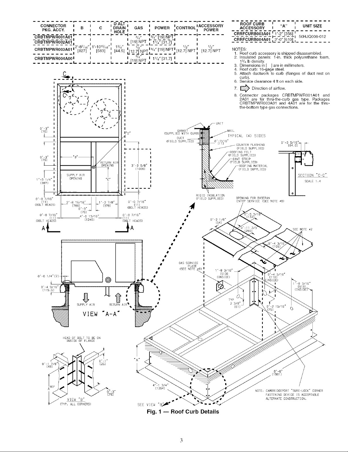
ROOF CURB -- Assemble and inst_dlthe accessoty roof curb
in accordance with instructions shipped with the curb. See
Fig. 1. Install insulation, cant strips, roofing felt, and counter
flashing as shown. Ductwork must be attached to the curb. If
electric or control power is to be routed through the basepan,
attach the accessory thru-the-bottom service connections to the
basepan in accor&mce with the accessory installation instruc-
tions. Connections must be installed before the unit is set on
roof curb.
SAFETY CONSIDERATIONS
Installation and servicing of air-conditioning equipment can
be hazardous due to system pressure and electtic_d compo-
nents. Only trained and qualified service personnel should
install, repair, or service ai>conditioning equipment.
Manufacturer reserves the right to discontinue, or change at any time, specifications or designs without notice and without incurring obligations.
Catalog No. 04-53500017-01 Printed in U.S.A, Form 50HJQ-17SI Pg 1 9-05 Replaces: 50HJQ-14SI
critical for watertightness. Install gasket supplied with the
roof curb as shown in Fig. 1. hnproperly applied gasket can
I IMPORTANT: The gasketing of the unit to the roof curb is I
also result in air leaks and poor unit performance.
I
Page 2
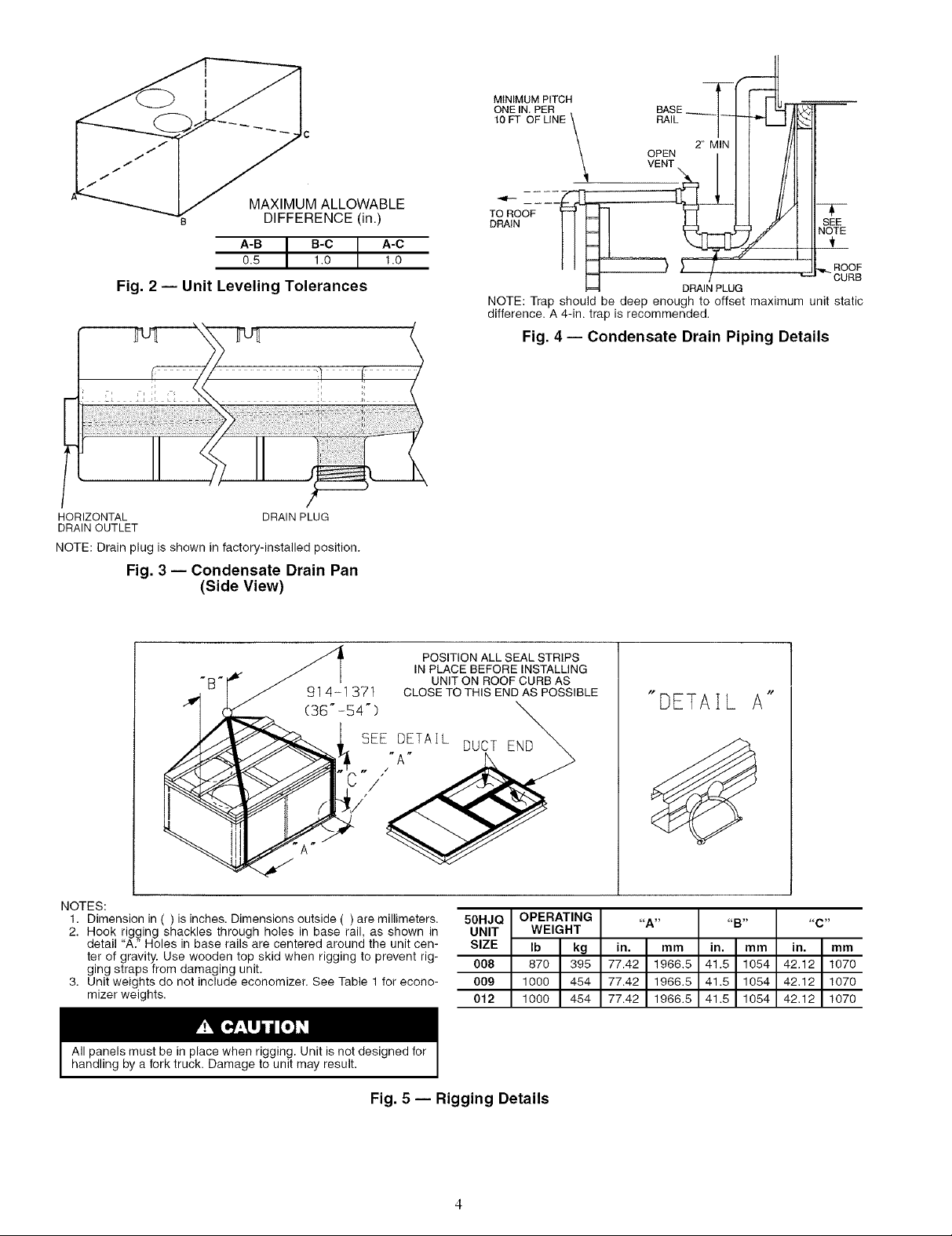
The roof curb should be level. Unit leveling tolerances am
shown in Fig. 2. This is necessmy for unit drain to function
properly. Refer to Accessory Roof Curb Installation Instruc-
tions for additional information, as required.
SLAB MOUNT (Horizontal Units Only) -- Provide a level
concrete slab that extends a minimum of 6 in. beyond file unit's
cabinet. Inst_fll a gravel apron in front of the condenser coil air
inlet to prevent grass and foliage from obstructing airflow.
NOTE: Horizontal units may be installed on a roof curb if
required.
ALTERNATE UNIT SUPPORT -- When the curb or adapter
cannot be used, support unit with sleepers using unit curb or
a&Tter support area. If sleepers cannot be used, support
the long sides of the unit with a minimum of 3 equally spaced
4-in. x 4-in. pads on each side.
Step 2 -- Field Fabricate Ductwork -- On vertic;d
discharge units, secure all ducts to the roof curb and building
structure. Do not connect ductwork to the unit. For horizontal
applications, field-supplied flanges should be attached to hori-
zontal discharge openings and all ductwork attached to the
flanges. Insulate and weatherproof all external ductwork,
joints, and roof openings with counter flashing and mastic in
accor&mce with applicable codes.
Ducts passing through an unconditioned space must be in-
sulated and covered with a vapor barriel:
If a plenum return is used on a vertical unit, the return
should be ducted through the roof deck to comply with applica-
ble fire codes.
A minimum clearance is not required around ductwork.
Cabinet return-air static pressure (a negative condition) should
not exceed 0.35 in. wg with economizer, or 0.45 in. wg without
economizer.
Step 3 -- Install Condensate Drain Line and
External Trap -- Condensate di'ain connections ;ue
located at the bottom and end of the unit. Unit discharge
connections do not determine the use of drain connections; use
either drain connection in vertic_d or horizontal applications.
When using the standmd end diain connection, make sure
the plug (Red) in the _dternate bottom connection is tight before
installing the unit.
To use the bottom drain connection for a roof curb installa-
tion, relocate the factory-installed plug (Red) from the bottom
connection to the end connection. Tile center di'ain plug looks
like a star connection, but can be removed with a I/2 in. socket
drive extension. See Fig. 3. The piping for the condensate di'ain
and external trap can be completed after the unit is in place.
All units must have an extern_fl trap for condensate di'ain-
age. [nstall a trap at least 4-in. deep and protect it against
freeze-up. If the drain line is installed downstream from the ex-
tern_d trap, pitch the line away from the unit at 1 in. per 10 ft of
run. Do not use a pipe size smaller than the unit connection
(314in.). See Fig. 4.
Step 4 -- Rig and Place Unit --Inspect the unit for
transportation damage. File any claim with the transportation
agency. Keep the unit upright and do not diop. Spreader bars
are not required if top crating is left on the unit. Rollers may be
used to move the unit across a roof. Level by using the unit
frame as a reference. See Table 1 and Fig. 5 for additional
information. Operating weight is shown in Table 1 and Fig. 5.
Lifting holes are provided in the base rails as shown in
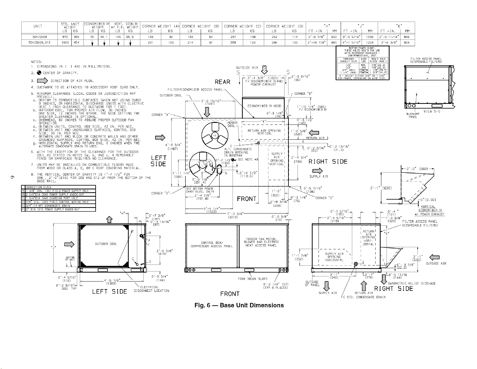
Fig. 5 and 6. Refer to the rigging instructions on file unit.
POSITIONING --Maintain clearance m'ound and above the
unit to provide proper airflow and service access. See Fig. 6.
Position the unit on the roof curb so that the following
clearances are maintained: %-in. clearance between roof
curb and base rails on each side and in duct end of unit;
3s/16-in. clearance between the roof curb and outdoor coil
end of the unit (see Fig. 1, section C-C).
Do not install the unit indoor._. Do not locate the unit's air
inlet near exhaust vents or other soumes of contaminated all:
Although the unit is weatherproof, gumd against water from
higher level runoff and overhangs.
After the unit is in position, remove the polyethylene ship-
ping wrapper and rigging skid.
Page 3
CONNECTOR ! B I C DRAIN GAS POWER .......
PKG. ACCY, I I I HOLE I I IL'UR/HUL I POWER
......... l-- -I -- I- -- - --I .... "$s ..... I ..... I--
CRB-TM-P-WR001-A0-11 I I , 3/4" _/4_"[_19]_N_P_ ,
i = I ACCESSORY
C_RB_TM2_WEO£2_AO_I,, , . [LCLN£Ti_lW'j_.7], ,
CRBTMPWROO3A01 [827] [583] [44.5] 127NPT /4" [19] NPT [12.7] NPT [12.7]NPT
CRBTMPWROO4AOOI I I I 3/4" I 1V4"[31.7] I I
2'-87/16" 1'-1015/16" 13/4" 1/2" 3 1/2" 1/2"
--I-- .J -- L. ....... I ..... I--
_i_It9_1_NP_T.
ROOF CURB I I
ACCESSORY I "A" I UNIT SIZE
"CRRF_U-RB0_3AOTII_ '---2'r[3_ 6_ I- - .........
NOTES:
1. Roof curb accessory is shipped disassembled.
2. Insulated panels: 1-in. thick polyurethane foam,
1s/4 Ib density.
3. Dimensions in [ ] are in millimeters.
4. Roof curb: 16-gage steel.
5. Attach ductwork to curb (flanges of duct rest on
curb).
6. Service clearance 4 ft on each side.
7. _ Direction of airflow.
8. Connector packages CRBTMPWROO1A01 and
2A01 are for thru-the-curb gas type. Packages
CRBTMPWROO3A01 and 4A01 are for the thru-
the-bottom type gas connections.
O" €"
[76]
0' €"
E7C]
1" 31/4" I
[38?3
[11]
(COLT CEACC)
O' O 7/15"
C" 0 1/4"[?]
[113_
I
CUPPLY AIR l
OPENING "C"
I
I
[786]
2" 6 15/1Gj
O'
[763
4' 0 13/16"
[1240]
I- D-
/
GASKET
(SUPPLIED WITH CURB;
DUCT
[FIELD SUPPLIED)
TYPICAL (4) S[OES
O" 7/15"
(FIELD SUPPLIED)
FLACB NG;
€" € €/€"
O" O 7/15"
(BOLT BEADS)
O' 0 7/1G"
(BO_TAEACC]
[11]
[IOO6]
RIGID INCULAT[ON
(FIELD CUPPLIED)
I
#
B [€4]
o' 2 1/8"
1" 8 3/16"
[513]
ClN5IOE)
(FIELD CUPPLIED) o
OPENING FOR CACEPAN
ENTRY CERVICE (CEE NOTE _€)
[290]
O' 4 5/16"
[llO]
INSIDE)
SECTION "C C"
CCALE 1=4
CEE NOTE #2
€/15"
HEAD OF BOLT TO BE ON
INSIDE OF FLANGE
O" 1 7/8"
[48]
_ (Ty p _/]AEL_ iOBRNERC )
4;
CUPPLY A[R
VIEW
"A-A"
O" l"
[25]
RETURN
R
I
SEE VIEW
4" 1 3/4"
[1264]
Fig. 1 -- Roof Curb Details
TYP
2 3/€ °
[51]
3]
I
I
I
I
I
G" G"
[1CC1]
NOTE= CAMCRIDGEPORT "CURE LOCK" CORNER
FACTEN[NG DEVICE IC ACCEPTABLE
ALTERNATE CONSTRUCT)ON,
Page 4
MINIMUM PITCH
ONE IN PER
lOFT ()F LINE
RA,LI itF
IIII
MAXIMUM ALLOWABLE
DIFFERENCE (in.)
A-B I B-C A-C
0.5 I 1.0 1.0
Fig. 2 -- Unit Leveling Tolerances
HORIZONTAL DRAIN PLUG
DRAIN OUTLET
NOTE:Drain plug is shown in factory-installed position.
Fig. 3 -- Condensate Drain Pan
(Side View)
91 4-1 371 CLOSE TO THIS ENDAS POSSIBLE
(36"-54") _,
T OOF
NOTE: Trap should be deep enough to offset maximum unit static
difference. A 4-in. trap is recommended.
POSITION ALL SEAL STRIPS
IN PLACE BEFORE INSTALLING
UNIT ON ROOF CURB AS
SEE DETAIL DUCT END
DRAIN PLUG
Fig. 4- Condensate Drain Piping Details
"DETAIL A"
T
SEE
NOTE
.._ROOF
CURB
NOTES:
1. Dimension in ( ) is inches. Dimensions outside ( ) are millimeters. 50HJQ
2. Hook rigging shackles through holes in base rail, as shown in UNIT
detail "A." Holes in base rails are centered around the unit cen- SIZE
ter of gravity. Use wooden top skid when rigging to prevent rig-
ging straps from damaging unit. 008
3. Unit weights do not include economizer. See Table 1 for econo- 009
mizer weights. 012
All panels must be in place when rigging. Unit is not designed for
handling by a fork truck. Damage to unit may result.
Fig. 5 -- Rigging Details
OPERATING
WEIGHT
Ib kg
870 395
1000 454
1000 454
_,A _,
in. mm
77.42 1966.5
77.42 1966.5
77.42 1966.5
in. mm
41.5 1054
41.5 1054
41.5 1054
,,C _,
in. mm
42,12 1070
42,12 1070
42,12 1070
Page 5
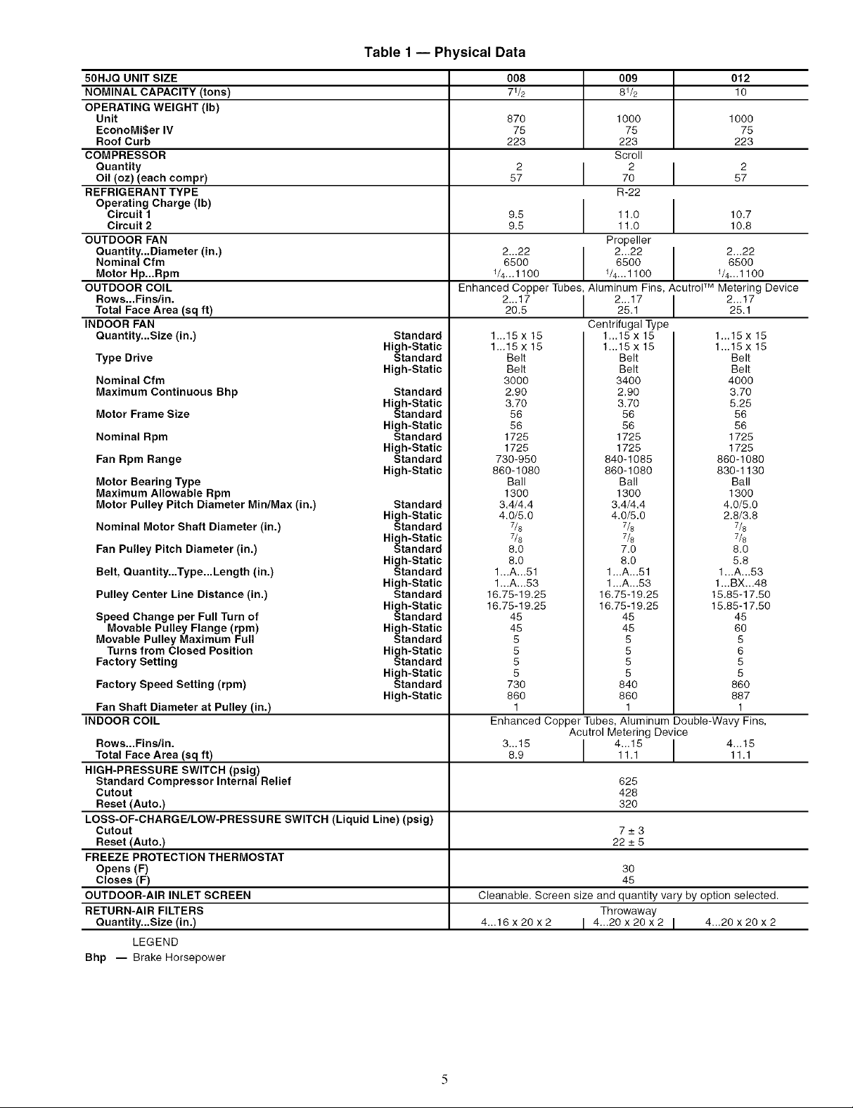
Table1-- Physical Data
50HJQ UNIT SIZE
NOMINAL CAPACITY (tons)
OPERATING WEIGHT (Ib)
Unit
EconoMiSer IV
Roof Curb
COMPRESSOR
Quantity
Oil (oz) (each compr)
REFRIGERANT TYPE
Operating Charge (Ib)
Circuit 1
Circuit 2
OUTDOOR FAN
Quantity...Diameter (in.)
Nominal Cfm
Motor Hp...Rpm
OUTDOOR COIL
Rows...Fins/in.
Total Face Area (sq ft)
INDOOR FAN
Quantity...Size (in.)
Type Drive
Nominal Cfm
Maximum Continuous Bhp
Motor Frame Size
Nominal Rpm
Fan Rpm Range
Motor Bearing Type
Maximum Allowable Rpm
Motor Pulley Pitch Diameter MiniMax (in.)
Nominal Motor Shaft Diameter (in.)
Fan Pulley Pitch Diameter (in.)
Belt, Quantity...Type...Length (in.)
Pulley Center Line Distance (in.)
Speed Change per Full Turn of
Movable Pulley Flange (rpm)
Movable Pulley Maximum Full
Turns from Closed Position
Factory Setting
Factory Speed Setting (rpm)
Fan Shaft Diameter at Pulley (in.)
INDOOR COIL
Rows...Fins/in.
Total Face Area (sq ft)
HIGH-PRESSURE SWITCH (psig)
Standard Compressor Internal Relief
Cutout
Reset (Auto.)
LOSS-OF-CHARGE/LOW-PRESSURE SWITCH (Liquid Line) (psig)
Cutout
Reset (Auto.)
FREEZE PROTECTION THERMOSTAT
Opens (F)
Closes (F)
OUTDOOR-AIR INLET SCREEN
RETURN-AIR FILTERS
Ouantity...Size (in.)
LEGEND
Bhp -- Brake Horsepower
Standard
High-Static
Standard
High-Static
Standard
High-Static
Standard
High-Static
Standard
High-Static
Standard
High-Static
Standard
High-Static
Standard
High-Static
Standard
High-Static
Standard
High-Static
Standard
High-Static
Standard
High-Static
Standard
High-Static
Standard
High-Static
Standard
High-Static
008 009 012
71/2 81/2 10
870 1000 1000
75 75 75
223 223 223
Scroll
2 I 2 I 257 70 57
R-22
9.5 11.0 10.7
9.5 11.O 10.8
2...22 2...22 I 2...22
6500 6500 I 65001/4...1100 1/4..,1100 1/4.,.1100
Enhanced Copper Tubes, Aluminum Fins, AcutroF M Metering Device
2...17 I 2...17 I 2...1720.5 25.1 25.1
1...15 x 15 1...15 x 15 1...15 x 15
1...15 x 15 1...15 x 15 1...15 x 15
Belt Belt Belt
Belt Belt Belt
3000 3400 4000
2.90 2,90 3,70
3.70 3.70 5.25
56 56 56
56 56 56
1725 1725 1725
1725 1725 1725
730-950 840-1085 860-1080
860-1080 860-1080 830-1130
Ball Ball Ball
1300 1300 1300
3.4/4.4 3.4/4.4 4.0/5,0
4.0/5.0 4.0/5.0 2.8/3,8
7/8 7/8 7/8
7/8 7/8 7/8
6.0 7.0 8.0
8.0 8.0 5.8
1...A...51 1...A...51 1...A...53
1...A...53 1...A...53 1...BX...48
16,75-19,25 16,75-19,25 15.85-17.50
16.75-19.25 16.75-19.25 15.85-17,50
45 45 45
45 45 60
5 5 5
5 5 6
5 5 5
5 5 5
730 840 860
860 860 887
1 1 1
Enhanced Copper Tubes, Aluminum Double-Wavy Fins,
3...15 I 4...15 I 4...156.9 11.1 11.1
Cleanable. Screen size and quantity vary by option selected.
4..,16x20x2 I 4...20x20x2 I 4._20x20x2
Propeller
Centrifugal Type
Acutrol Metering Device
625
428
32O
7_+3
22_+5
3O
45
Throwaway
Page 6
UNIT HEIGHT HEIGHT W/ P E. WEIGHT CORNER WEIGHT (A) CORNER WEIGHT (B) CORNER WEIGHT (C) CORNER WEIGHT (D) "N"
5OHJQOO8 870 395 3 1 1 BSI 9 198 90 183 83 237 108 252 114 2' 0 7/8" 532
SOHJQOO9,012 lOOO 231 105 214 97 269 122 285 130 2" 10 7/8" 885
NOTES=
1. DIMENSIONS IN [ ] ARE iN MILLIMETERS.
2. _CENTER OF GRAVITY.
3. _ DIRECTION OF AIR FLOW.
4. DUCTWORK TO BE ATTACHED TO ACCESSORY ROOF CURB ONLY.
5. MINIMUM CLEARANCE (LOCAL CODES OR JURISDICTION MAY
PREVAIL):
o. BOTTOM TO COMBUSTIBLE SURFACES (WHEN NOT USING CURB)
O INCHES, ON HORIZONTAL DISCHARGE UNITS HITH ELECTRIC
HEAT 1 INCH CLEARANCE TO DUCTWORK FOR 1 FOOT.
b. OUTDOOR COIL, FOR PROPER AIR FLOW, 35 INCHES
ONE SIDE, 12 INCHES THE DTHER. THE SIDE GETTING THE
CREATER CLEARANCE 15 OPTIONAL.
c. OVERHEAD, 50 INCHES TO ASSURE PROPER OUTDOOR FAN
OPERATION.
d. BETWEEN UNITS, CONTROL BOX SIDE, 42 IN. PER NEC.
e. BETWEEN UNIT AND UNGROUNDED SURFACES, CONTROL BOX
SIDE, 35 IN. PER NEC.
F. BETWEEN UNIT AND BLOCK OR CONCRETE WALLS AND OTHER
GROUNDED SURFACES, CONTROL BOX SIDE, 42 IN. PER NEC.
9- HORIZONTAL SUPPLY AND RETURN END, 0 INCHES WHEN THE
ALTERNATE CONDENSATE DRAIN IS USED.
5. WITH THE EXCEPTION OF THE CLEARANCE FOR THE OUTDOOR
COIL AS STATED IN NOTES 5u, b, AND c, A REMOVABLE
FENCE OR BARRICADE REQUIRES NO CLEARANCE.
7. UNITS MAY BE INSTALLED ON COMBUSTIBLE FLOORS MADE
FROM HOOD OR CLASS A, B, OR C ROOF COVERING MATERIAL.
8.
THE VERTICAL CENTER OF GRAVITY [5 1" 7 1/2" FOR
OOB , 2' 0"[510] FOR 009 AND 012 UP FROM THE BOTTOH OF THE
BASE RAILI
I 3Z8"
DIA. [35] FIELD POWER SUPPLY HOLE
5TO. UNIT ECONOMIZER IV HERT ECON IV
LB 45KG4 LBT_ KG4_ LBiS KG LB KG LB KG LB KG LB KG FT IN. MM
SIZES
" "F ?
OF UNIT
BOTTOM
O" 4_9/16"
[llB]
0" 2 9/18 "_"
[55] TYP
i
OUTDOOR COIL L C 2['510913/8"
_,_ r--m \ EC
"
LEFT SIDE DISCONNECTLOCATION
FILTER/ECONOMIZER ACCE55 PANEL
OUTDOOR COIL
CORNER "A'_
4" 9 3/4"
[1467]
LEFT
SIDE
CORNER "D "_
-- D.EI 4HB.
B [B7]
OUTSIDE AIR
s S
REAR
3'[%91] ECONOMISER IV HOOD I_/I0 1/4" [555]
/_'I"f-_INDOOR I 11403
ALT. CONDENSATE I I
II IN BASEPAN
_O DRAIN OPENING
II ' ? 1/21_SEE NOTE #E
SEE BOTTOM POWER
CHART (ELEC, ONLY)
F/ ECONOMISER IVAND [BO]
POWER EXHAUST
O" 3 1/8"
[79] _
I RETURN AIR OPENING I l" O 5/B _
, VERTICAL _ [320]
_ _ RETURN AIR
I SUPPLy I
AIR I
I I
I I
I I
(_B1.B_ FRONT
_3' 4 1/4"_
El022]
CONTROL BOX/ BLOWER AND ELECTRIC
COMPRESSOR ACCESS PANEL HEAT ACCESB PANEL
7' 3 3/8"
[2219]
FORK TRUCK SLOTS
INDOOR FAN MOTOR.
[20B]
O' 0 3/8"
[IO] _
O" 2 1/4" [573
(TYP B PLACE5)
FRONT
CORNER "B"
ECONOMIGER IV
(_50_RIGHT SIDE
SUPPLY AIR
' 5 ?/16"
[79]
CORNER "C"
SUPPLY AIR \ I I
I HORIZONTAL I [635]
OF PANEL _'BAROMETRIC RELIEF D[SCHAGE
OHTSIDE 8 __ 1_
SUPPLY AIR / RETURN AIR
Fig. 6 -- Base Unit Dimensions
• jr "K"
3" 5 5/18" 1050 2' 9 11/16" 856
FT IN. MM B' 0 3/8 _ MM4" 1 5/18" FT IN.
THESEHOLES REQ'D FOR USE
WITH ACCESSORYPACKAGES
O" 7 5/1 G"
[lB5]
[719]
OPENING I 2" 1"
3" l" ll/16
[940] El 78] El 44]
1253 924
BOTTOMPOWERCHART=
CRBTMPWROO1A01,2A01
2" I"
O" 4 ° ECONOMISER IV
[I01] H/ POWER EXHAH5T
1" O 5/B"
[320] FILTER ACCE55 PANEL
I
I RETURN
AIR
IDPENING
I
ZONTAL
I
I
I OUTSIDE AIR
FILTER ACCE5S PANEL
(DISPOSABLE FILTERS)
BLOCKOFF
PANEL
RIGHT SIDE
LE 5TD. CONDENSATE DRAIN
r-----n
VIEW S S
O" [O OO]
VERTICAL
FILTERS)
I
Page 7
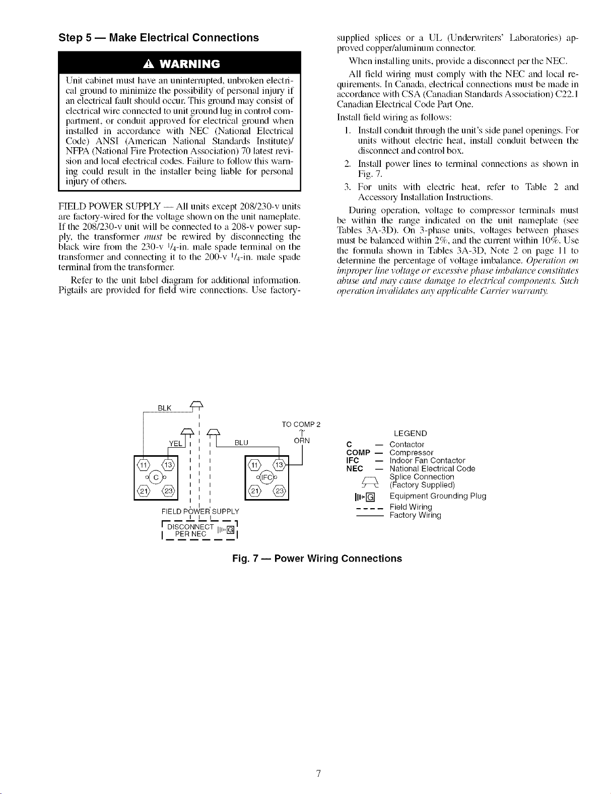
Step 5 -- Make Electrical Connections
Unit cabinet must have an uninterrupted, unbroken electri-
cal ground to minimize the possibility of personal inju U if
an electrical fault should occm_ This ground may consist of
electrical wire connected to unit ground lug in control com-
partment, or conduit approved for electrical ground when
installed in actor&race with NEC (National Electrical
Code) ANSI (American Nation_d Standiu_ds Institute)/
NFPA (Natiomd Fire Protection Association) 70 latest revi-
sion and local electric_d codes. Failure to follow this warn-
ing could result in the installer being liable for persomd
inju U of others.
FIELD POWER SUPPLY -- All units except 208/230-v units
are factory-wired for the voltage shown on the unit nameplate.
If the 208/230-v unit will be connected to a 208-v power sup-
ply, the transformer must be rewired by disconnecting the
black wire fiom the 230-v l/4-in, male spade temrinal on the
transformer and connecting it to the 200-v l/4-in, m_de spade
terminal fiom the transformel_
Refer to the unit label diagram for additional infommtion.
Pigtails are provided for field wire connections. Use facto U-
supplied splices or a UL (Underwriters' Laboratories) ap-
proved copper/aluminum connectol:
When inst_dling units, provide a disconnect per the NEC.
All field wiring must comply with the NEC and local re-
quirements. In Canada, electrical connections must be made in
accor&mce with CSA (Canadian Stan&_rds Association) C22.1
Canadian Electric_d Code Part One.
Inst_dl field wiring as follows:
1. Inst_dl conduit through the unit's side panel openings. For
units without electric heat, install conduit between the
disconnect and control box.
2. Inst_dl power lines to terminal connections as shown in
Fig. 7.
3. For units with electric heat, refer to Table 2 and
Accessory Installation Instructions.
During operation, voltage to compressor terminals must
be within the range indicated on the unit nameplate (see
Tables 3A-3D). On 3-phase units, voltages between phases
must be balanced within 2%, and the current within 10%. Use
the formula shown in Tables 3A-3D, Note 2 on page 11 to
determine the percentage of voltage imbalance. Operation on
iml)rOl)er line voltage or (_rcessive phase imbalance constitutes
abuse and may cause damage to electrical components. Such
ol)eration invalidaws an)" applicable Carrier warrant).'.
BLK
FIELD POWER SUPPLY
I I I
I DISCONNECTII,'IN]
[ PER NEC
TO COMP 2
T
BLU ORN
C -- Contactor
COMP- Compressor
IFC -- Indoor Fan Contactor
NEC -- National Electrical Code
[ll.rG-] Equipment Grounding Plug
-- Factory Wiring
Fig. 7-- Power Wiring Connections
LEGEND
Splice Connection
(Factory Supplied)
Field Wiring
Page 8
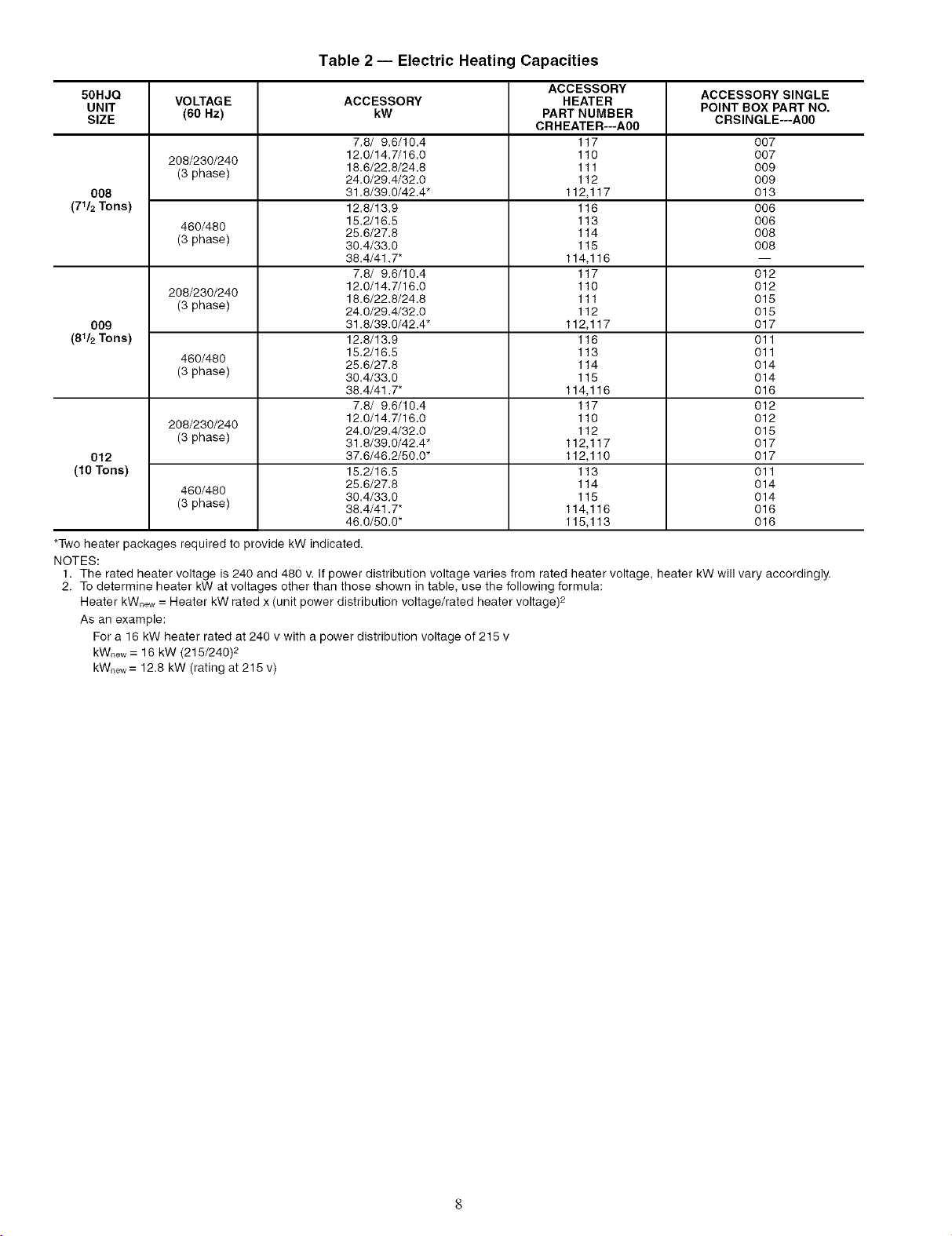
Table 2 -- Electric Heating Capacities
50HJQ VOLTAGE ACCESSORY HEATER
UNIT (60 Hz) kW PART NUMBER POINT BOX PART NO.
SIZE CRSINGLE---A00
7.8/ 9.6/10.4 117 007
208/230/240 12.0/14.7/18.0 110 007
(3 phase) 16.6/22.6/24.8 111 009
008 31.8/39.0/42.4" 112,117 013
(71/2Tons) 12.6/13.9 116 008
460/480 15.2/16.5 113 008
(3 phase) 38.4/33.0 115 008
208/230/240 18.6/22.8/24.8 111 015
(3 phase) 24.0/29.4/32.0 112 015
009 31.8/39.0/42.4" 112,117 017
(81/2Tons) 12.8/13.9 116 011
460/480 25.6/27.8 114 014
(3 phase) 30.4/33.0 115 014
208/230/240 24.0/29.4/32.0 112 015
(3 phase) 31.8/39.0/42.4" 112,117 017
012 37.6/46.2/50.0" 112,110 017
(10 Tons) 15.2/16.5 113 011
460/480 30.4/33. O 115 014
(3 phase) 38.4/41.7" 114,116 016
*Two heater packages required to provide kW indicated.
NOTES:
1. The rated heater voltage is 240 and 480 v. If power distribution voltage varies from rated heater voltage, heater kW will vary accordingly.
2. To determine heater kW at voltages other than those shown in table, use the following formula:
Heater kWnew= Heater kW rated x (unit power distribution voltage/rated heater voltage) 2
As an example:
For a 16 kW heater rated at 240 v with a power distribution voltage of 215 v
kWnew= 16 kW (215/240) 2
kWnew= 12.8 kW (rating at 218 v)
24.0/29.4/32.0 112 009
25.6/27.8 114 008
38.4/41.7" 114,116 --
7.8/ 9.6/10.4 117 012
12.0/14.7/16.0 110 012
15.2/16.5 113 011
38.4/41.7" 114,116 016
7.8/ 9.6/10.4 117 012
12.0/14.7/16.0 110 012
25.6/27.8 114 014
46.0/50.0" 115,113 016
ACCESSORY ACCESSORY SINGLE
CRHEATER---A00
Page 9
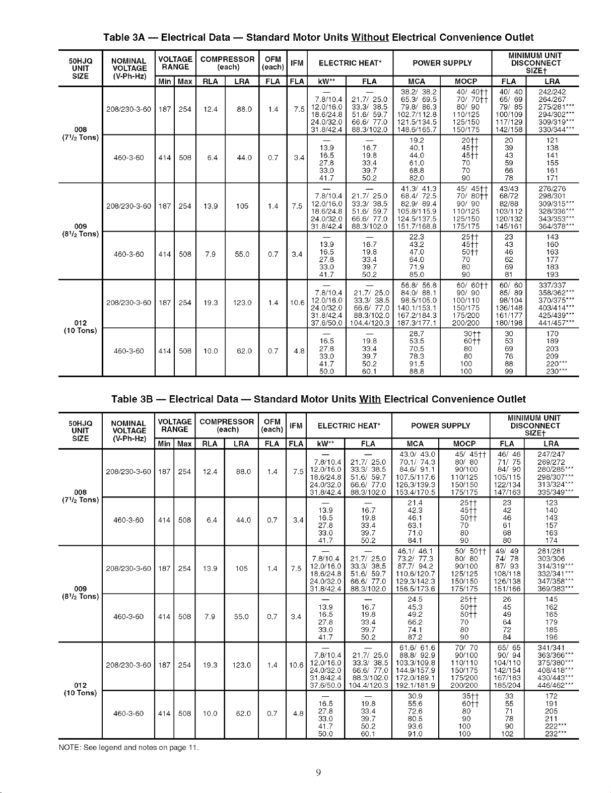
Table 3A -- Electrical Data -- Standard Motor Units Without Electrical Convenience Outlet
50HJQ
UNIT
SIZE
O08
(7112 Tons)
009
(8112Tons)
012
(10 Tons)
NOMINAL VOLTAGE COMPRESSOR OFM IFM ELECTRIC HEAT*
VOLTAGE RANGE (each) (each)
(V-Ph-Hz) Min Max RLA LRA FLA FLA kW** FLA
208/230-3-60 187 254 12.4 88.0 1.4 7.5 12.0/16.0 33.3/ 38.5
460-3-60 414 508 6.4 44.0 0.7 3.4 16.5 19.8
208/230-3-60 187 254 13.9 105 1.4 7.5 12.0/16.0 33.3/ 38.5
460-3-60 414 508 7.9 55.0 0.7 3.4 16.5 19.8
208/230-3-60 187 254 19.3 123.0 1.4 10.6 12.0/16.0 33.3/ 38.5
460-3-60 414 508 10.0
62.0 0.7 4.8 27,8 33.4
78/10.4 217/ 250
18.6/24.8 51.6/ 59,7
24.0/32.0 66.6/ 77.0
31.8/42.4 88.3/102.0
13.9 16.7
27.8 33.4
33.0 39,7
41.7 50.2
7.8/10.4 21.7/ 25,0
18.6/24.8 51.6/ 59,7
24.0/32.0 66.6/ 77.0
31.8/42.4 88.3/102.0
13.9 16.7
27,8 33.4
33.0 39,7
41.7 50.2
7.8/10.4 21.7/ 25.0
24.0/32.0 66.6/ 77.0
31,8/42,4 88.3/102,0
37.6/50.0 104.4/120.3
16,5 19.8
33.0 39,7
41,7 50,2
50.0 60.1
POWER SUPPLY
MCA
38.2/ 38.2
65.3/ 69.5
79.8/ 86.3
102.7/112.8
121.5/134.5
148.6/165.7
19,2
40.1
44.0
61.0
68.8
82.0
41.3/ 41.3
68.4/ 72.5
82.9/ 89.4
105.8/115.9
124.5/137.5
151.7/168.8
22.3
43,2
47.0
64.0
71.9
85.0
56.8/ 56.8
84.0/ 88.1
98.5/105.0
140.1/153.1
167.2/184.3
187.3/177.1
28.7
53,5
70.5
78.3
91.5
88.8
MINIMUM UNIT
DISCONNECT
SIZEt
MOCP FLA LRA
40/ 40tt 40/ 40 242/242
70/ 70tt 65/ 69 264/267
80/ 90 79/ 85 275/281"**
110/125 100/109 294/302"**
125/150 117/129
150/175 142/158
2Oft 20
451t 39
45ft 43
70 59
70 66
90 78
45/ 45it 43/43
70/ 80tt 68/72
90/ 90 82/88
110/125 103/112
125/150 120/132
175/175 145/161
25ft 23
45ft 43
5Oft 46
70 62
80 69
90 81
60/ 6Oft 60/ 60
90/ 90 85/ 89
100/110 98/104
150/175 136/148 403/414***
175/200 161/177 425/439"**
200/200 180/198 441/457"**
30tt 30 170
60tf 53 189
80 69 203
80 76 209
100 88 220***
100 99 230***
309/319***
330/344"**
121
138
141
155
161
171
276/276
298/301
309/315"**
328/336"**
343/353"**
364/378"**
143
160
163
177
183
193
337/337
358/362"**
370/375"**
Table 3B -- Electrical Data -- Standard Motor Units With Electrical Convenience Outlet
50HJQ
UNIT
SIZE
OO8
(7112 Tons)
009
(8112Tons)
012
(10 Tons)
NOTE: See legend and notes on page 11.
NOMINAL VOLTAGE COMPRESSOR OFM
VOLTAGE RANGE (each) (each) IFM ELECTRIC HEAT*
(V-Ph-Hz) Min Max RLA LRA FLA FLA kW** FLA
208/230-3-60 187 254 12.4
460-3-60 414 508 6.4
208/230-3-60 187 254 13.9 105
460-3-60 414 508 7.9 55.0
208/230-3-60 187 254 19.3 123.0
460-3-60 414 508 10.0 62.0
88.0 1.4 7.5 12.0/16.0 33.3/ 38.5
44.0 0.7 3.4 16.5 19.8
1.4 7.5 12.0/16.0 33.3/ 38.5
0.7 3.4 16.5 19.8
1.4 10.6 12.0/16.0 33.3/ 38.5
0.7 4.8 27.8 33.4
7.8/10.4 21.7/ 25.0
18.6/24.8 51.6/ 59.7
24.0/32.0 66.6/ 77.0
31.8/42.4 88.3/102.0
13.9 16.7
27.8 33.4
33.0 39.7
41.7 50.2
7.8/10.4 21.7/ 25.0
18.6/24.8 51.6/ 59.7
24.0/32.0 66.6/ 77.0
31.8/42.4 88.3/102.0
13.9 16.7
27.8 33.4
33.0 39.7
41.7 50.2
7.8/10.4 21.7/ 25.0
24.0/32.0 66.6/ 77.0
31.8/42.4 88.3/102.0
37.6/50.0 104.4/120.3
16.5 19.8
33.0 39.7
41,7 50.2
50.0 60.1
POWER SUPPLY
MCA
43,0/ 43.0
70.1/ 74.3
84,6/ 91.1
107.5/117.6
126.3/139.3
153.4/170.5
21.4
42.3
46.1
63.1
71.0
84.1
46.1/ 46.1
73.2/ 77.3
87.7/ 94.2
110.6/120.7
129.3/142.3
156.5/173.6
24.5
45.3
49.2
66.2
74.1
87.2
61.6/ 61.6
88.8/ 92.9
103.3/109.8
144.9/157.9
172.0/189.1
192.1/181.9
30.9
55.6
72.6
80.5
93.6
91.0
MINIMUM UNIT
DISCONNECT
SIZEt
MOCP FLA LRA
45/ 45tt 46/ 46 247/247
80/ 80 71/ 75 269/272
90/100 84/ 90 280/285"**
110/125 105/115 298/307"**
150/150 122/134 313/324"**
175/175 147/163 335/349"**
25¢t 23 123
45ft 42 140
5Oft 46 143
70 61 157
80 68 163
90 80 174
50/ 50tt 49/ 49 281/281
80/ 80 74/ 78 303/306
90/100 87/ 93 314/319"**
125/125 108/118 332/341 ***
150/150 126/138 347/358"**
175/175 151/166 369/383"**
25it 26 145
5Oft 45 162
5Oft 49 165
70 64 179
80 72 185
90 84 196
70/ 70 65/ 65 341/341
90/1 O0 90/ 94 363/366"**
110/110 104/110 375/380"**
150/175 142/154 408/418***
175/200 167/183 430/443"**
200/200 185/204 446/462"**
35tt 33 172
60tf 55 191
80 71 205
90 78 211
100 90 222***
100 102 232***
Page 10
50HJQ
UNIT
SIZE
O08
(7412Tons)
009
(8412Tons)
012
(10 Tons)
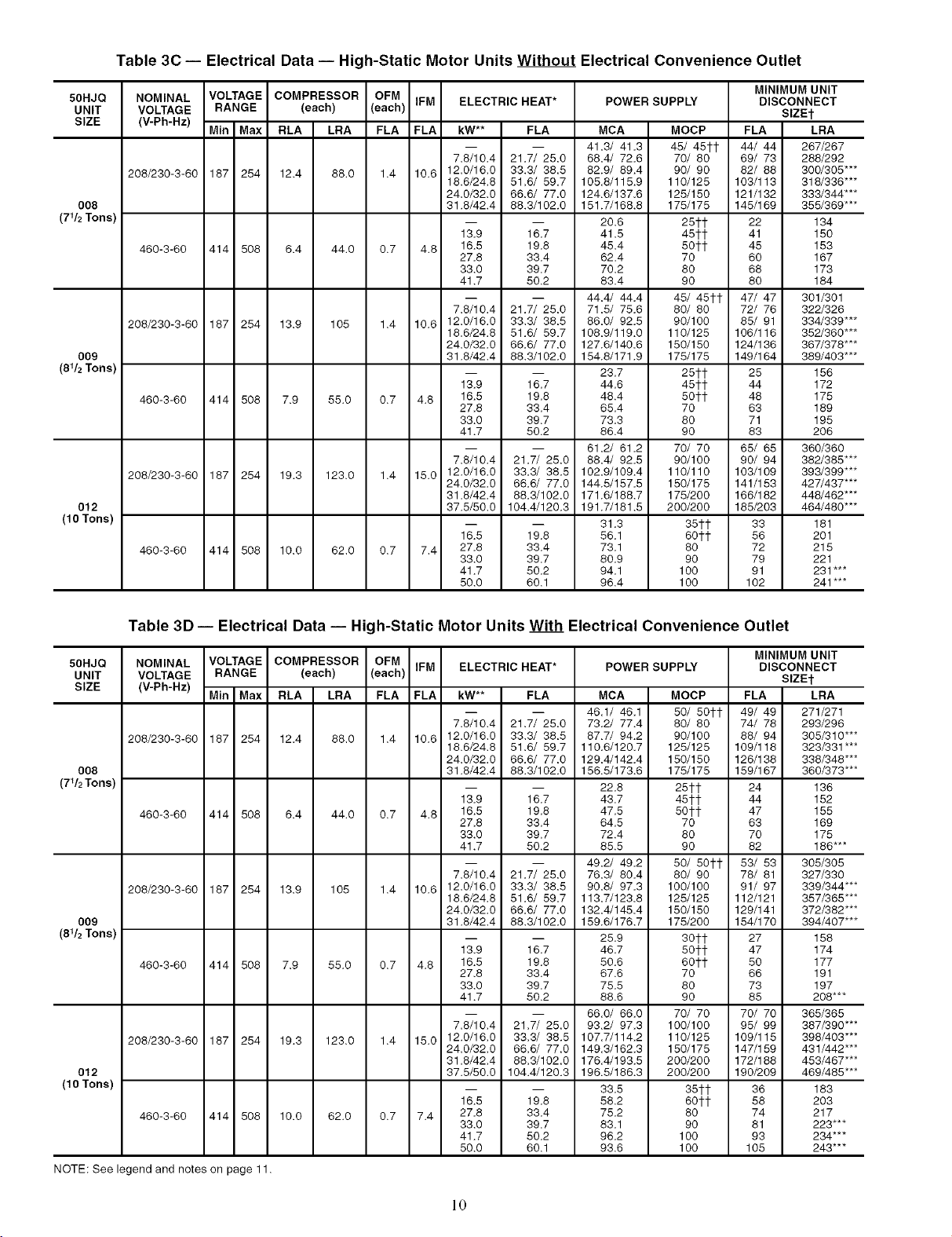
Table 30 -- Electrical Data -- High-Static Motor Units Without Electrical Convenience Outlet
NOMINAL VOLTAGE COMPRESSOR OFM IFM ELECTRIC HEAT*
VOLTAGE RANGE (each) (each)
(V-Ph-Hz)
208/230-3-60 187 254 12.4
460-3-60 414 508 6.4
208/230-3-60 187 254 13.9 105
460-3-60 414 508 7.9 55.0
208/230-3-60 187 254 19.3 123.0
460-3-60 414 508 10.0 62.0
Min Max RLA LRA FLA FLA kW** FLA
88.0 1.4 10.6 12.0/16.0 33.3/ 38.5
44.0 0.7 4.8 16.5 19.8
1.4 10.6 12.0/16.0 33.3/ 38.5
0.7 4.8 16.5 19.8
1.4 15.0 12.0/16.0 33.3/ 38.5
0,7 7,4 27.8 33.4
7.8/10.4 21.7/ 25.0
18.6/24.8 51.6/ 59,7
24.0/32.0 66.6/ 77.0
31.8/42.4 88.3/102.0
13.9 16.7
27.8 33.4
33.0 39.7
41.7 50.2
7.8/10.4 21.7/ 25.0
18.6/24.8 51.6/ 59,7
24.0/32.0 66.6/ 77.0
31.8/42.4 88.3/102.0
13.9 16.7
27.8 33.4
33.0 39.7
41.7 50.2
7.8/10.4 21.7/ 25.0
24.0/32.0 66.6/ 77.0
31,8/42.4 88.3/102.0
37.5/50.0 104.4/120.3
16.5 19.8
33,0 39.7
41.7 50.2
50,0 60,1
POWER SUPPLY
MCA
41 3/ 41.3
68.4/ 72.6
82.9/ 89.4
105.8/115.9
124.6/137.6
151.7/168.8
20.6
41.5
45.4
62,4
70.2
83.4
44.4/ 44.4
71.5/ 75.6
86.0/ 92.5
108.9/119,0
127.6/140.6
154.8/171.9
23.7
44.6
48.4
65.4
73.3
86.4
61.2/ 61.2
88.4/ 92.5
102.9/109.4
144.5/157.5
171.6/188.7
191.7/181.5
31.3
56.1
73.1
80.9
94.1
96.4
MOCP FLA LRA
45/ 45tt 44/ 44 267/267
70/ 80 69/ 73 288/292
90/ 90 82/ 88 300/305"**
110/125 103/113 318/336"**
125/150 121/132 333/344"**
175/175 145/169 355/369"**
251-1- 22 134
451-1- 41 150
501-1- 45 153
70 60 167
80 68 173
90 80 184
45/ 451-1- 47/ 47 301/301
80/ 80 72/ 76 322/326
90/100 85/ 91 334/339"**
110/125 106/116 352/360"**
150/150 124/136 367/378"**
175/175 149/164 38_403"**
251-1- 25 156
451-1- 44 172
501-1- 48 175
70 63 189
80 71 195
90 83 206
70/ 70 65/ 65 360/360
90/100 90/ 94 382/385"**
110/110 103/109 39_399"**
150/175 141/153 42_437"**
175_00 166/182 44_462"**
200_00 185_03 464/480"**
351-1- 33 181
601-1- 56 201
80 72 215
90 79 221
100 91 231"**
100 102 241"**
MINIMUM UNIT
DISCONNECT
SIZEt
Table 3D -- Electrical Data -- High-Static Motor Units With Electrical Convenience Outlet
50HJQ
UNIT
SIZE
O08
(7412Tons)
009
(8412Tons)
012
(10 Tons)
NOTE: See legend and notes on page 11.
NOMINAL VOLTAGE COMPRESSOR OFM IFM ELECTRIC HEAT*
VOLTAGE RANGE (each) (each)
(V-Ph-Hz)
208/230-3-60 187 254 12.4
460-3-60 414 508 6.4
208/230-3-60 187 254 13.9 105
460-3-60 414 508 7.9 55.0
208/230-3-60 187 254 19.3 123.0
460-3-60 414 508 10.0 62.0
Min Max RLA LRA FLA FLA kW** FLA
88.0 1.4 10.6 12.0/16.0 33.3/ 38.5
44.0 0.7 4.8 16.5 19.8
1.4 10.6 12.0/16.0 33.3/ 38.5
0.7 4.8 16.5 19.8
1.4 15.0 12.0/16.0 33.3/ 38.5
0.7 7.4 27.8 33.4
7.8/10.4 21.7/ 25.0
18.6/24.8 51.6/ 59.7
24.0/32.0 66.6/ 77.0
31.8/42.4 88.3/102.0
13.9 16.7
27.8 33.4
33.0 39.7
41.7 50.2
7.8/10.4 21.7/ 25.0
18.6/24.8 51.6/ 59.7
24.0/32.0 66.6/ 77.0
31.8/42.4 88.3/102.0
13.9 16.7
27.8 33.4
33.0 39.7
41.7 50.2
7.8/10.4 21.7/ 25.0
24.0/32.0 66.6/ 77.0
31,8/42.4 88.3/102.0
37.5/50.0 104.4/120.3
16.5 19.8
33.0 39.7
41.7 50.2
50.0 60.1
POWER SUPPLY
MCA
461/ 46.1
73.2/ 77.4
87,7/ 94.2
110.6/120.7
129.4/142.4
156.5/173.6
22.8
43.7
47.5
64.5
72.4
85.5
49.2/ 49.2
76.3/ 80.4
90.8/ 97.3
113.7/123.8
132.4/145.4
159.6/176.7
25.9
46.7
50.6
67.6
75.5
88.6
66.0/ 66.0
93.2/ 97.3
107.7/114.2
149.3/162.3
176.4/193.5
196.5/186.3
33.5
58.2
75.2
83.1
96.2
93.6
MINIMUM UNIT
DISCONNECT
SEE1-
MOCP FLA LRA
50/ 501-1- 49/ 49 271/271
80/ 80 74/ 78 293/296
90/100 88/ 94 305/310"**
125/125 109/118 323/331"**
150/150 126/138 338/348"**
175/175 159/167 360/373"**
251-1- 24 136
451-1- 44 152
501-1- 47 155
70 63 169
80 70 175
90 82 186"**
50/ 501-1- 53/ 53 305/305
80/ 90 78/ 81 327/330
100/100 91/ 97 339_44"**
125/125 112/121 357_65"**
150/150 129/141 372_82"**
175_00 154/170 394/407"**
301-1- 27 158
501-1- 47 174
601-1- 50 177
70 66 191
80 73 197
90 85 208***
70/ 70 70/ 70 365/365
100/100 95/ 99 387_90"**
110/125 109/115 398/403"**
150/175 147/159 431/442"**
200_00 172/188 453/467"**
200_00 190_09 469/485"**
351-1- 36 183
601-1- 58 203
80 74 217
90 81 223***
100 93 234***
100 105 243***
]0
Page 11
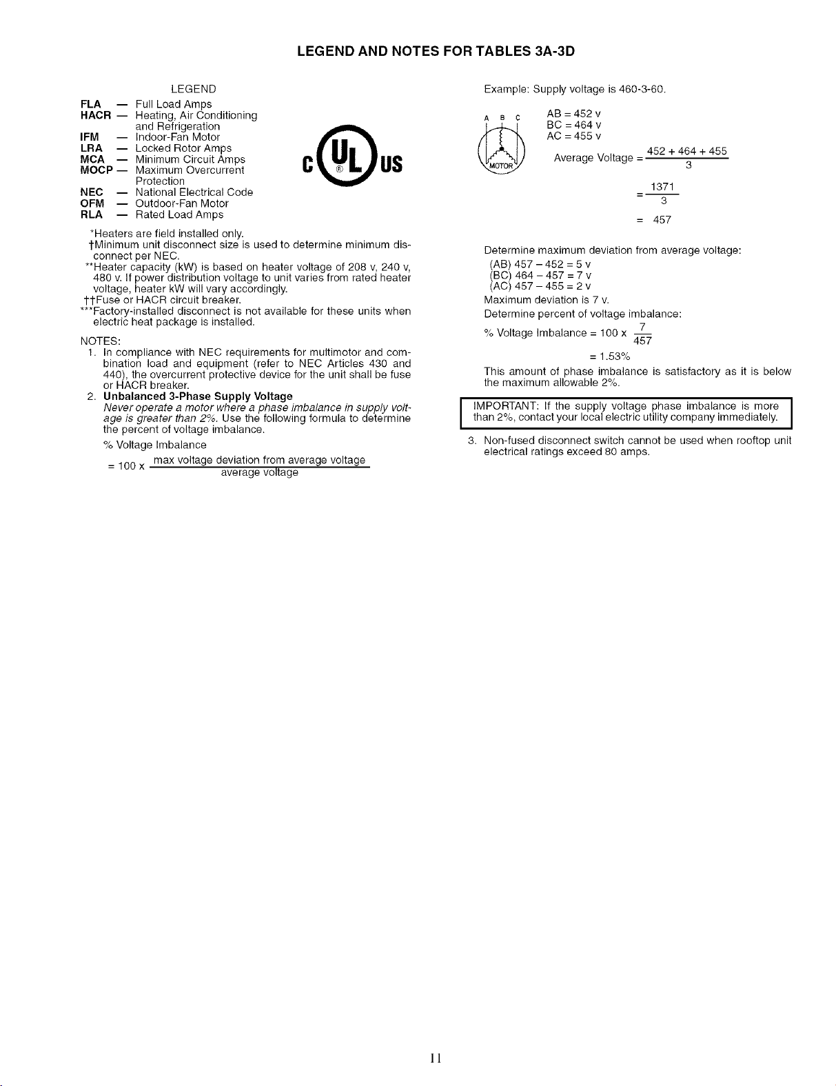
LEGEND AND NOTES FOR TABLES 3A-3D
LEGEND
FLA -- Full Load Amps
HACR -- Heating, Air Conditioning
IFM -- Indoor-Fan Motor
LRA -- Locked Rotor Amps
MCA -- Minimum Circuit Amps
MOCP -- Maximum Overcurrent
NEC -- National Electrical Code
OFM -- Outdoor-Fan Motor
RLA -- Rated LoadAmps
*Heaters are field installed only.
1-Minimum unit disconnect size is used to determine minimum dis-
connect per NEC.
**Heater capacity (kW) is based on heater voltage of 208 v, 240 v,
480 v. If power distribution voltage to unit varies from rated heater
voltage, heater kW will vary accordingly.
1-1-Fuseor HACR circuit breaker.
***Factory-installed disconnect is not available for these units when
electric heat package is installed.
NOTES:
1. In compliance with NEC requirements for multimotor and com-
2. Unbalanced 3-Phase Supply Voltage
and Refrigeration
Protection
bination load and equipment (refer to NEC Articles 430 and
440), the overcurrent protective device for the unit shall be fuse
or HACR breaker.
Never operate a motor where a phase imbalance in supply volt-
age is greater than 2%. Use the following formula to determine
the percent of voltage imbalance.
% Voltage Imbalance
= 100 x max voltage deviation from average voltage
average voltage
Example: Supply voltage is 460-3-60.
A B C
Determine maximum deviation from average voltage:
(AB) 457 - 452 = 5 v
(BC) 464 - 457 = 7 v
(AC) 457 - 455 = 2 v
Maximum deviation is 7 v.
Determine percent of voltage imbalance:
% Voltage Imbalance = 100 x --
This amount of phase imbalance is satisfactory as it is below
the maximum allowable 2%.
than 2%, contact your local electric utility company immediately.
I IMPORTANT: If the supply voltage phase imbalance is more I
3. Non-fused disconnect switch cannot be used when rooftop unit
electrical ratings exceed 80 amps.
AB = 452 v
BC = 464 v
AC = 455 v
452 + 464 + 455
Average Voltage = 3
1371
3
= 457
7
457
= 1.53%
I
]!
Page 12
HELD CONTROL WIRING -- Install a Carrier-approved
accessory thennostat assembly according to the installation
instructions included with the accessory. Locate file thermostat
assembly on a solid wall in the conditioned space to sense
average temperature in accor&mce with thermostat installa-
tion instructions.
NOTE: If using a Carrier electronic thermostat, set the thenno-
star configuration for "non-heat pump operation." This family
of products does not require an O temfinal to energize the
reversing valve.
Route the thermostat cable or equivalent single leads of col-
ored wire from the subbase termimds to the low-voltage con-
nections on the unit (shown in Fig. 8A and 8B) as described in
Steps 1 fllrough 4 below.
NOTE: For wire runs up to 50 ft, use no. 18 AWG (American
Wire Gage) insukited wire (35 C minimum). For 51 to 75 1l, use
no. 16 AWG insukited wire (35 C minimum). For over 75 fi, use
no. 14 AWG insukited wire (35 C minimum). All wire larger
than no. 18 AWG cannot be directly connected to the thermostat
and will require ajunction box and splice at the thermostat.
1. If the unit is mounted on the roof curb and an accessory
thin-the-curb service plate connection is used, route the
wire through connection plate.
2. Pass control wires through the hole provided on the unit
(see connection D in the Connection Sizes table in
Fig. 6).
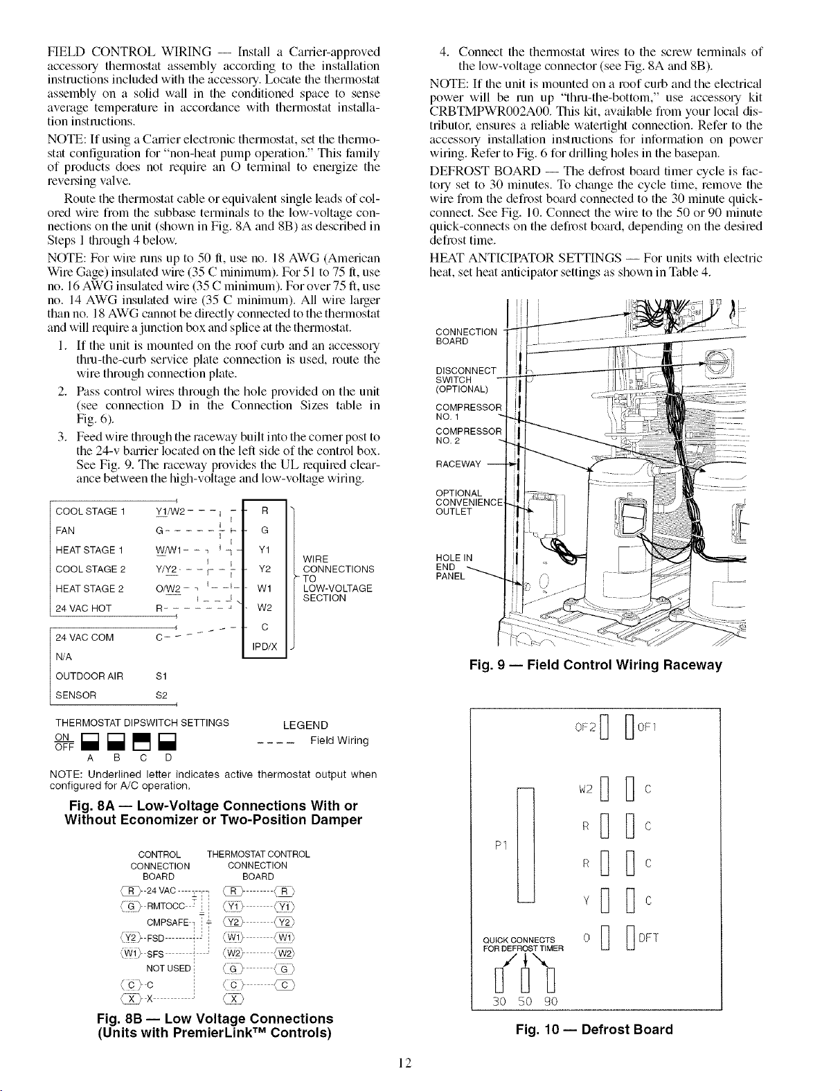
3. Feed wire through the raceway built into the comer post to
the 24-v bmrier located on the left side of the control box.
See Fig. 9. The raceway provides the UL lequiled clear-
ance between the high-voltage and low-voltage wiring.
m
COOL STAGE 1 Y1/W2 - - - i
FAN G -
HEAT STAGE 1 W/W1- - _ I _
COOL STAGE 2 Y/Y2- - - F -
HEAT STAGE 2 O/W2 - _ i _ -I-
24 VAC HOT R-
24 VAC COM C-
N/A
OUTDOOR AIR $1
SENSOR $2
- R
I
- G
I
I
Y1
- Y2
W1
, W2
- C
IPD/X
WIRE
CONNECTIONS
-TO
LOW-VOLTAGE
SECTION
4. Connect the thermostat wires to the screw terminals of
the low-voltage connector (see Fig. 8A and 8B).
NOTE: If the unit is mounted on a roof curb and the electrical
power will be run up "thru-the-bottom," use accessory kit
CRBTMPWR002A00. This kit, av_dlable from your local dis-
tributor, ensures a reliable watertight connection. Refer to the
accessory installation instructions for information on power
wiring. Refer to Fig. 6 for drilling holes in the basepan.
DEFROST BOARD -- The defrost board timer cycle is fac-
tory set to 30 minutes. To chtmge the cycle time, remove the
wire from the defrost board connected to the 30 minute quick-
connect. See Fig. 10. Connect the wire to the 50 or 90 minute
quick-connects on the defrost board, depending on the desired
defmst time.
HEAT ANTICIPATOR SETTINGS -- For units with electric
heat, set heat anticipator settings as shown in Table 4.
CONNECTION
BOARD
DISCONNECT
SWITCH
(OPTIONAL)
COMPRESSOR
NO. 1
NO. 2
RACEWAY
OPTIONAL
CONVENIENCE'
OUTLET
HOLEIN
END
i
Fig. 9 -- Field Control Wiring Raceway
THERMOSTAT DIPSWITCH SETTINGS LEGEND
O_F [] [] [] [] FieldWiring
A B C D
NOTE: Underlined letter indicates active thermostat output when
configuredfor A/C operation.
Fig. 8A- Low-Voltage Connections With or
Without Economizer or Two-Position Damper
CONTROL THERMOSTAT CONTROL
CONNECTION CONNECTION
BOARD BOARD
/_R_R )_ 24 vAC _ll _ (FLIP
{[::_[) RMTOOC 7ii (,[?_'5 ,/[_J[>
CMPSAFE7 i" <_
< Y27 ESD I 1 <[_i) <_!)
(Wl)_ SFS _ 1
NOT USED ;
=,
1 1
c
(g2_x <x)
Fig. 8B -- Low Voltage Connections
(Units with PremierLink Controls)
TM
12
OF2_ _OF1
P1
QUICK CONNECTS
FOR DEFROST TIMER
oI]
30 50 90
Fig. 10 -- Defrost Board
I]
[1I-1
Page 13
UNIT
50HJQ
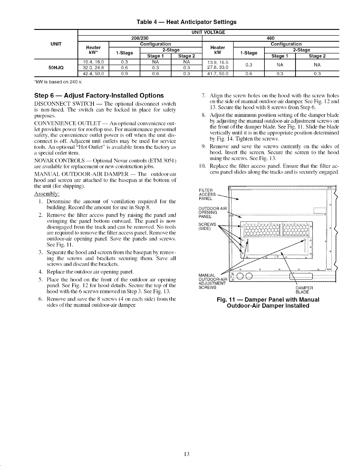
*kW is based on 240 v.
Heater
kW*
10.4, 16.0
32.0, 24.8
42.4, 50.0
Table 4 -- Heat Anticipator Settings
208/230
Configuration
2-Stage
1-Stage Stage 1 Stage 2
0.3 NA NA
0.6 0.3 0.3
0.9 0.6 0.3
UNIT VOLTAGE
Heater
kW
13.9, 16.5
27.8, 33.0
41.7, 50.0
1-Stage
0.3
0.6
46O
Configuration
2-Stage
Stage 1 Stage 2
NA NA
0.3 0.3
Step 6 -- Adjust Factory-Installed Options
DISCONNECT SWITCH -- The optional disconnect switch
is non-fused. The switch can be locked in place for safety
purposes.
CONVENIENCE OUTLET -- An optiomd convenience out-
let provides power for rooftop use. For maintenance personnel
safety, the convenience outlet power is off when the unit dis-
connect is off. Adjacent unit outlets may be used for service
tools. An optional "Hot Outlet" is available from file factory as
a speci_d order item.
NOVAR CONTROLS -- Option_d Novar controls (ETM 3051 )
ale available for leplacement or new construction jobs.
MANUAL OUTDOOR-AIR DAMPER -- The outdoor-air
hood and screen me attached to the basepan at the bottom of
the unit (for shipping).
Assemblys.:
1. Determine the amount of ventilation required for the
building. Record the amount for use in Step 8.
2. Remove the filter access panel by raising the panel and
swinging the panel bottom outward. The panel is now
disengaged from the track and can be removed. No tools
are requiled to remove the filter access panel. Remove the
outdoor-air opening panel. Save the panels and screws.
See Fig. 11.
3. Separate file hood and screen from the basepan by remov-
ing file screws and brackets securing them. Save all
screws and discmd the brackets.
4. Replace the outdoor air opening panel.
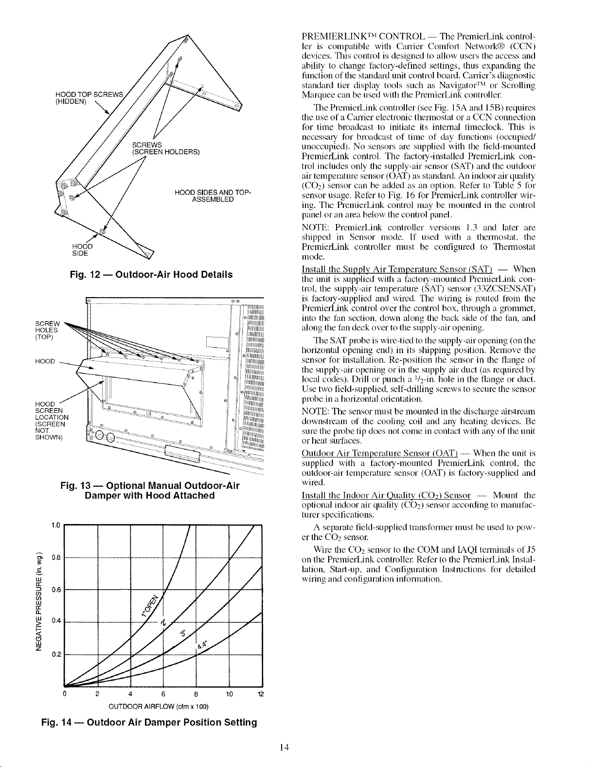
5. Place the hood on the front of the outdoor air opening
panel. See Fig. 12 for hood details. Secure the top of the
hood with the 6 screws removed in Step 3. See Fig. 13.
6. Remove and save the 8 screws (4 on each side) from the
sides of the manual outdoor-air &tmpel:
7. Align the screw holes on the hood with the screw holes
on the side of manual outdoor-air dampel: See Fig. 12 and
13. Secure the hood with 8 screws fiom Step 6.
8. Adjust the minimum position setting of the &tmper blade
by adjusting the manual outdoor-air adjustment screws on
file front of the &tmper blade. See Fig. 11. Slide the blade
vertically until it is in file appropriate position determined
by Fig. 14. Tighten the screws.
9. Remove and save the screws currently on the sides of
hood. Insert the screen. Secure the screen to the hood
using the screws. See Fig. 13.
10. Replace the filter access panel. Ensure that the filter ac-
cess panel slides along the tracks and is securely engaged.
ADJUSTMENT
SCREWS
DAMPER
BLADE
Fig. 11 -- Damper Panel with Manual
Outdoor-Air Damper Installed
13
Page 14
HOOD TOP SCREWS
(HIDDEN) _.,
SCREWS
(SCREEN HOLDERS)
HOOD SIDES AND TOP-
ASSEMBLED
HOOD
SIDE
Fig. 12 -- Outdoor-Air Hood Details
SCREW
HOLES
(TOP)
HOOD
HOOD
SCREEN
LOCATION
(SCREEN
NOT
SHOWN)
Fig. 13- Optional Manual Outdoor-Air
Damper with Hood Attached
1.0
0.8 / /
LU
rr
0,6
60
PREMIERLINK TM CONTROL -- The PmmierLink control-
let is compatible with Career Comfort Network® (CCN)
devices. This control is designed to allow users the access and
ability to change factory-defined settings, thus expanding the
function of file standiu'd unit control board. Career's diagnostic
standard tier display tools such as Navigator TM or Scrolling
Marquee can be used with the PremierLink controller.
The PremielLink controller (see Fig. 15A and 15B) requires
the use of a Carrier electronic thermostat or a CCN connection
for time broadcast to initiate its intermfl fimeclock. This is
necessary for broadcast of time of &ty functions (occupied/
unoccupied). No sensors me supplied with the field-mounted
PremierLink control. The factory-installed PremierLink con-
trol includes only the supply-air sensor (SAT) and the outdoor
air temperature sensor (OAT) as standard. An indoor air quality
(CO2) sensor can be added as an option. Refer to Table 5 for
sensor usage. Refer to Fig. 16 for PmmierLink controller wir-
ing. The PremierLink control may be mounted in file control
panel or an area below the control panel.
NOTE: PmmierLink controller versions 1.3 and later am
shipped in Sensor mode. If used with a thermostat, the
PmmierLink controller must be configured to Themlostat
mode.
Install the Supply Air Temperature Sensor (SAT) -- When
the unit is supplied with a factory-mounted PremierLink con-
trol, the supply-air temperature (SAT) sensor (33ZCSENSAT)
is factory-supplied and wired. The wiring is routed from file
PmmierLink control over the control box, through a grommet,
into the fan section, down _flong the back side of the fan, and
along the fan deck over to the supply-air opening.
The SAT probe is wire-tied to the supply-air opening (on the
horizontal opening end) in its shipping position. Remove the
sensor for installation. Re-position the sensor in file flange of
the supply-air opening or in file supply air duct (as lequimd by
loc_fl codes). Drill or punch a 1/2-in. hole in the flange or duct.
Use two field-supplied, self-drilling screws to secure the sensor
probe in a horizontal orientation.
NOTE: The sensor must be mounted in the dischmge airstmam
downstream of file cooling coil and any heating devices. Be
sum the probe tip does not come in contact wifll any of the unit
or heat surfaces.
Outdoor Air Temperature Sensor (OAT) -- When the unit is
supplied with a factory-mounted PremierLink control, the
outdoor-_dr temperature sensor (OAT) is factory-supplied and
wimdi
Install the Indoor Air Quality (CO_ Sensor -- Mount the
optional indoor air quality (Ci2)2) sensor according to manufac-
turer specifications.
A separate field-supplied transformer must be used to pow-
er the CO2 sensor:
Wile the CO2 sensor to the COM and IAQI terminals of J5
on the PremierLink controllec Refer to the PremierLink Instal-
lation, Start-up, and Configuration Instructions for detailed
wiring and configuration information.
# 0.4 /
0 2 4 8 10 12
OUTDOOR AIRFLOW (cfm x 100)
Fig. 14 -- Outdoor Air Damper Position Setting
14
Page 15
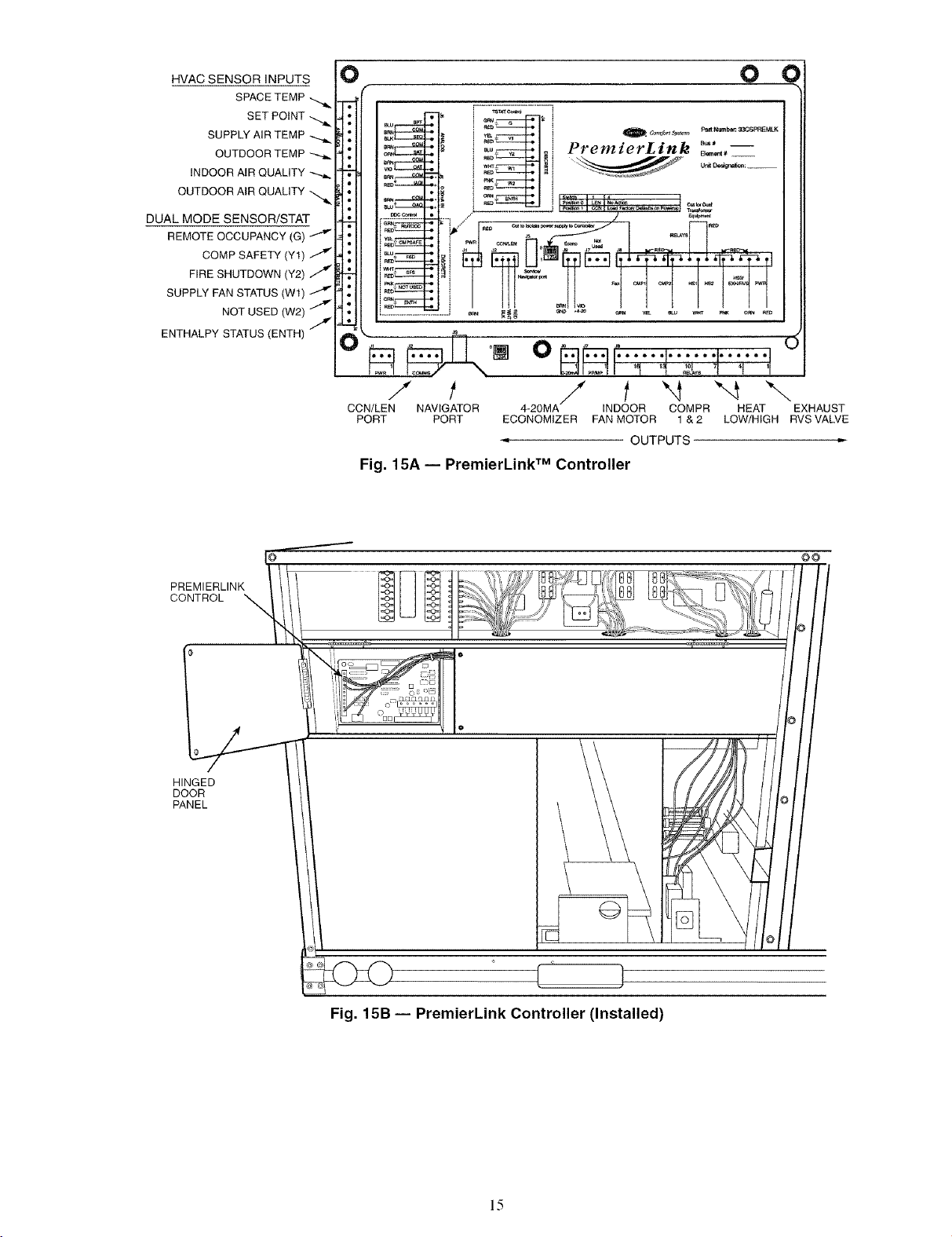
HVAC SENSOR INPUTS
SPACE TEMP
SET POINT
SUPPLY AIR TEMP
OUTDOOR TEMP -_.
INDOOR AIR QUALITY
OUTDOOR AIR QUALITY
DUAL MODE SENSOR/STAT
0 0 €
am" _f_
................ _ .- J
_ _ _ut N_ber 33C_pP_=_K
.-_c_]_ PremzerLznk .....
COMP SAFETY (Y1) J
FIRE SHUTDOWN (Y2) Z
SUPPLY FAN STATUS (Wl)
NOT USED (W2) J
ENTHALPY STATUS (ENTH) Z
PREMIERLINK
CONTROL
tb-_- i I-_ @H, _r:-ar-_ _ _ _ " "
, 7°1.o lqo_,.'_°,,= ..I ,.-.._ I I _
--' "C'ITTIT I'
.......................... J _ P_ N _ *.-_ _N Y_ _ _ _ O_ _ED
/ t / t "4 "-4 \
CCN/LEN
PORT
Fig. 15A -- PremierLink TM Controller
NAVIGATOR 4-20MA INDOOR COMPR HEAT EXHAUST
PORT ECONOMIZER FAN MOTOR 1 & 2 LOW/HIGH RVSVALVE
OUTPUTS
HINGED
DOOR
PANEL
Fig. 15B -- PremierLink Controller (Installed)
15
Page 16
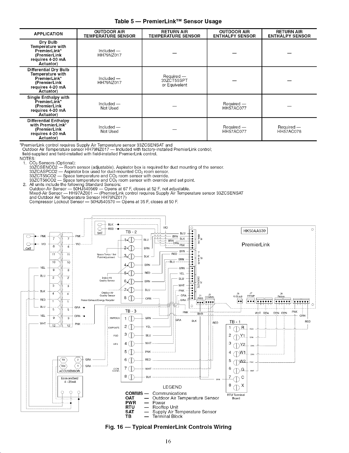
Table 5- PremierLink TM Sensor Usage
APPLICATION TEMPERATURE SENSOR TEMPERATURE SENSOR ENTHALPY SENSOR ENTHALPY SENSOR
Dry Bulb
Temperature with
PremierLink* Included --
(PremierLink HH79NZ017
requires 4-20 mA
Actuator)
Differential Dry Bulb
Temperature with Required --
PremierLink* Included -- 33ZCT55SPT -- --
(PremierLink HH79NZ017
requires 4-20 mA or Equivalent
Actuator)
Single Enthalpy with
PremierLink*
(PremierLink Included -- _ Required -- _
requires 4-20 mA
Actuator)
Differential Enthalpy
with PremierLink*
(PremierLink Included -- _ Required -- Required --
requires 4-20 mA
Actuator)
*PremierLink control requires Supply Air Temperature sensor 33ZCSENSAT and
Outdoor Air Temperature sensor HH79NZ017 -- included with factory-installed PremierLink control
field-supplied and field-installed with field-installed PremierLink control.
NOTES:
1. CO2 Sensors (Optional):
33ZCSENCO2 -- Room sensor (adjustable). Aspirator box is required for duct mounting of the sensor.
33ZCASPCO2 -- Aspirator box used for duct-mounted CO2 room sensor.
33ZCT55CO2 -- Space temperature and CO2 room sensor with override.
33ZCT56CO2 -- Space temperature and CO2 room sensor with override and set point.
2. All units include the following Standard Sensors:
Outdoor-Air Sensor -- 50HJ540569 -- Opens at 67 F, closes at 52 F, not adjustable.
Mixed-Air Sensor -- HH97AZ001 -- (PremierLink control requires Supply Air Temperature sensor 33ZCSENSAT
and Outdoor Air Temperature Sensor HH79NZ017)
Compressor Lockout Sensor -- 50HJ540570 -- Opens at 35 F, closes at 50 R
OUTDOOR AIR RETURN AIR OUTDOOR AIR RETURN AIR
Not Used HH57AC077
Not Used HH57AC077 HH57AC078
............. BLK
iiiii-°L°
PNK
YEL
RED
BLU
YEL
WHT
HK50AA039]
VIO
6
10
2 ¸
3 ¸
EconomiSer2
4 - 20mA
i VlO
Power Exhaust'Energy Recycle r
SpaceTemp/ Set i
PointAd}ustment
]ndoofAk
Oua]_y Sensor
Outdoor Air
Quality Sensor
6_
i_ ii1
8 (_ ............. ORN
YEL
BLU
PNK I
RED
7 <I_
8r]rh
COMMS -- Communications
OAT
PWR
RTU
SAT
TB
WNT
k_U]
BLK
LEGEND
-- Outdoor Air Temperature Sensor
-- Power
-- Rooftop Unit
-- Supply Air Temperature Sensor
-- Terminal Block
PremierLink
J9 J7 J8
O-20 mA PPIMP Relays
TB- 1
_ED
t SII_ R
2 /ll _Y1
i
3 _/I _Y2
5 SIIhW2
6 /I]\GG
\J[/
<JJ
\JL/
\ HJ
RE_ '
ORN '" _ i
ORN ' '
PNK ,,
Wm
7 S j--, C
8_X
<IL;
RTU Terminal
Board
RED
Fig. 16 -- Typical PremierLink Controls Wiring
16
Page 17

Enthalpy Sensors and Control -- Tile enthalpy control
(HH57AC077) is supplied as a field-inst_dled accessory to be
used with the economizer damper control option. The outdoor
air enthalpy sensor is part of the enthalpy control. The separate
field-inst_dled accessory return air enthalpy sensor
(HH57AC078) is required for differential enthalpy control.
NOTE: Tile enthalpy control must be set to the "D" setting for
differential enthalpy control to work properly.
Tile enthalpy control receives the indoor and return
enthalpy from the outdoor and return _firenthalpy sensors and
provides a &'y contact switch input to the PremierLink TM
controllel: Ix_cate the controller in place of an existing econo-
mizer controller or near the actuatol: Tile mounting plate may
not be needed if existing bracket is used.
A closed contact indicates that outside air is preferred to the
return all: An open contact indicates that the economizer
should remtfin tit minimum position.
Outdoor Air Enthalpy Sensor/Enthalpy Controller
(HH57AC077) -- To wile the outdoor air enthalpy sensor.
perform the following (see Fig. 17 and 18):
NOTE: The outdoor air sensor can be removed from the back
of the enthalpy controller and mounted remotely.
1. Use a 4-conductor. 18 or 20 AWG cable to connect the
enthalpy control to the PlemierLink controller and power
transformeE
2. Connect the following 4 wires from the wire harness
located in rooftop unit to the enth_dpy controller:
a. Connect the BRN wire to the 24 vac terminal (TRI)
on enthalpy control and to pin 1 on 12-pin harness.
b. Connect the RED wire to the 24 vac GND terminal
(TR) on enthalpy sensor and to pin 4 on 12-pin
harness.
c. Connect the GRAY/ORN wire to J4-2 on Premier-
Link controller and to terminal (3) on enthalpy
sensoL
d. Connect the GRAY/RED wire to J4-1 on Premier-
Link controller and to termimd (2) on enth_dpy sensol:
NOTE: If installing in a Carrier rooftop, use the two gray wires
provided from the control section to the economizer to connect
PmmierLink controller to terminals 2 and 3 on enthalpy sensor
If NOT using Carrier equipment, wires may need to be field
supplied and inst_dled.
Return Air Enthalpy Sensor -- Mount the return-air enthalpy
sensor (HH57AC078) in the return-air duct. The return air
sensor is wired to the enthalpy controller (HH57AC077). The
outdoor enthalpy changeover set point is set tit the controllel:
To wire the return air enthalpy sensol; perform the follow-
ing (see Fig. 17):
1. Use a 2-conductor. 18 or 20 AWG, twisted pair cable to
connect the return air enthalpy sensor to the enthalpy
controller
2. At the enthalpy control remove the factory-installed
resistor from the (SR) and (+) terminals.
3. Connect file field-supplied RED wire to (+) spade
connector on the return air enthalpy sensor and the (SR+)
terminal on the enthalpy controllel: Connect the BLK
wire to (S) spade connector on the return air enthalpy
sensor and the (SR) terminal on the enthalpy controller.
ENTHALPY CONTROLLER
TRr_TRI[_- --
@c so0
SRI-h+lD"
LED
NOTES:
1. Remove factory-installed jumper across SR and + before con-
necting wires from return air sensor.
2. Switches shown in high outdoor air enthalpy state. Terminals 2
and 3 close on low outdoor air enthalpy relative to indoor air
enthalpy.
3. Remove sensor mounted on back of control and locate in out-
side airstream.
RED
BRN
GRAY/ORN
GRAY/RED jIN UNIT
[_t (OUTDOOR
BLK SENSOR)
RED
_WlRE HARNESS
AIR
ENTHALPY
r]s (RETURN AIR
[7+ ENTHALPY
SENSOR)
Fig. 17 -- Outside and Return Air Sensor Wiring
Connections for Differential Enthalpy Control
HH57AC077
ENTHALPY
CONTROLAND
OUTDOOR AIR
ENTHALPY SENSOR
HH57AC078 ENTHALPY
SENSOR (USED WITH
ENTHALPY CONTROL
FOR DIFFERENTIAL
ENTHALPY OPERATION)
÷ ÷
MOUNTING PLATE
Fig. 18- Differential Enthalpy Control,
Sensor and Mounting Plate (33AMKITENT006)
17
Page 18

OPTIONAL ECONOMI$ER IV AND ECONOMI$ER2 --
See Fig. 19 for EconoMiSer IV component locations. See
Fig. 20 for EconoMiSer2 component locations.
NOTE: These instructions are for installing the optional
EconoMiSer IV and EconoMiSer2 only. Refer to the accessory
EconoMiSer IV or EconoMi$er2 inst¢fllafion instructions when
field installing an EconoMiSer IV or EconoMiSer2 accessory.
1. To remove the existing unit filter access panel, raise the
panel and swing the bottom outwcud. Tile panel is now
disengaged fiom the track and can be removed. See
Fig. 21.
2. The box with the economizer hood components is
shipped in the compartment behind the economizel: The
EconoMiSer IV controller is mounted on top of the
EconoMi$er IV in the position shown in Fig. 19. The
optional EconoMiSer2 with 4 to 20 mA actuator sigmd
control does not include the EconoMiSer [V controllel:
To remove the component box from its shipping position,
remove the screw holding the hood box bracket to the top
of the economizer Slide the hood box out of the unit. See
Fig. 22.
IMPORTANT: If the power exhaust accessory is to be ]
inst_flled on the unit, the hood shipped with the unit will not
be used and must be discarded. Save the aluminum filter
for use in the power exhaust hood assembly.
3. The indoor coil access panel will be used as the top of the
hood. Remove the screws along the sides and bottom of
the indoor coil access panel. See Fig. 23.
4. Swing out indoor coil access panel and insert the hood
sides under the panel (hood top). Use the screws provided
to attach the hood sides to the hood top. Use screws pro-
vided to attach the hood sides to the unit. See Fig. 24.
5. Remove the shipping tape holding the economizer baro-
metric relief &_mper in place.
6. Insert the hood divider between the hood sides. See
Fig. 24 and 25. Secme hood divider with 2 sclews on
each hood side. The hood divider is also used as the bot-
tom filter rack for the aluminum filtec
7. Open the filter clips which _ue located underneath the
hood top. Insert the aluminum filter into the bottom filter
rack (hood divider). Push the filter into position past the
open filter clips. Close the filter clips to lock the filter into
place. See Fig. 25.
8. Caulk the ends of the joint between the unit top panel and
the hood top. See Fig. 23.
9. Replace the filter access panel.
10. Install all EconoMi$er IV accessories. EconoMi$er IV
wiring is shown in Fig. 26. EconoMi$er2 wiring is shown
in Fig. 27.
Barometric flow capacity is shown in Fig. 28. Outdoor air
leakage is shown in Fig. 29. Return air pressure diop is shown
in Fig. 30.
ECONOMI$ER IV STANDARD SENSORS
Outdoor Air Temperature (OAT) Sensor -- The outdoor air
temperature sensor (HH57AC074) is a 10 to 20 mA device
used to measure the outdoor-air temperatme. The outdoor-air
temperature is used to determine when the EconoMiSer IV can
be used for free cooling. The sensor is factory-installed on the
EconoMiSer IV in the outdoor airstremn. See Fig. 19. The
operating range of temperature measurement is 40 to 100 E
Supply Air Temperature (SAT) Sensor -- The supply air
temperature sensor is a 3 K thermistor located at the inlet of the
indoor fan. See Fig. 31. This sensor is factory installed. The
operating range of temperature measurement is 0° to 158 E See
Table 6 for sensor temperature/resistance values.
I
The temperature sensor looks like an eyelet terminal with
wires running to it. The sensor is located in the "crimp end"
and is sealed from moisture.
Outdoor Air Lockout Sensor -- The EconomiSer IV is
equipped with an ambient temperatme lockout switch located
in the outdoor air stream which is used to lockout the compres-
sors below a 42 F ambient temperature. See Fig. 19.
ECONOMISER IV
-CONTROLLER
OUTSIDE AIR
HARNESS
ACTUATOR-
/ TEMPERATURE SENSOR
LOW AMBIENT
SENSOR
/
/ ;
Fig. 19 -- EconoMiSer IV Component Locations
OUTDOOR
AIR HOOD
cc_
/
BAROMETRIC
RELIEF
DAMPER
Fig. 20 -- EconoMi$er2 Component Locations
FILTER ACCESS PANEL
INDOOR COILACCESS PANEL
Fig. 21 -- Typical Access Panel Locations
/
GEAR DRIVEN
DAMPER
18
Page 19

HOOD BOX
BRACKET
/ /
/ I I
I I
I !
l /
! !
I J
i !
I
I
' 0
l
/
!
!
/
Fig. 22 -- Hood Box Removal
SIDE
PANEL
TOP
SIDE
PANEL
INDOOR
COIL
ACCESS
PANEL
\\
INDOOR
COIL
ACCESS
PANEL
Fig. 23 -- Indoor Coil Access Panel Relocation
TOP
ALUMINUM
FILTER
BAROMETRIC ,
RELIEF
Fig. 25 -- Filter Installation
Table 6 -- Supply Air Sensor
Temperature/Resistance Values
TEMPERATURE (F) RESISTANCE (ohms)
-58 200,250
-40 100,680
-22 53,010
-4 29,091
14 16,590
32 9,795
50 5,970
68 3,747
77 3,000
86 2,416
104 1,597
122 1,080
140 746
158 525
176 376
185 321
194 274
212 203
230 153
248 116
257 102
266 69
284 70
302 55
FILTER
CLIP
LEFT
SIDE
HOOD DIVIDER
Fig. 24 i Outdoor-Air Hood Construction
INDOORCOIL
ACCESS PANEL
ECONOMISER IV CONTROL MODES
IMPORTANT: The optional EconoMiSer2 does not
include a controllen The EconoMiSer2 is operated by a 4 to
20 mA signed _oln an existing field-supplied controller
(such as PremierLink TM control). See Fig. 27 for wiling
information.
Determine the EconoMiSer IV control mode before set up of
the control Some modes of operation may require different sen-
sors. Refer to Table 7. The EconoMiSer IV is supplied from the
factory with a supply-air temperature sensor and an outdoor air
temperature sensol: This allows for operation of the
EconoMi$er IV with outdoor air dry bulb changeover control.
Additional accessories can be added to allow for different types
of changeover control and operation of the EconoMiSer IV and
unit.
19
Page 20

,FIELD
ACCESSORY)
REMOTE_IN N
POSITIONPOT BLK
FIELD_S_LL_ - I
OArFE.P,÷AO
ERTHALPY SERSOR
RAT/ENTHALPY SENSOR
(FIELD ACCESSORY) __L
)AO,_
SR+ FREE AB_ _
FOR OCCUPANCY CONTROL
REPLACE JUMPER WITH
FIELD-SUPPLIED TIME CLOCK
f/ VIO-
BLR
EXF
[]SE_ )
2V )OV )
[].I
OPEN
RV IOV
2V tOv
)ECONOMISER 11
)
)
PO',
i
i
i
i
i
i
i
EXH _ BOARD
PM_
O
FIELD SPLICE
TAN
TO PWR XHAUST
ACCESSORY
BLK
ECONOMIZER MOTOR
WHT_
RED
_BLK
--GRY_
Y£L_
FIELD SPLICE,
_ BRN
PL6÷R
(NOT USED)
(NOT USED)
(NOT USED)
ORY
OR°
(NOT USED)
LEGEND
DCV-- Demand Controlled Ventilation
IAQ -- Indoor Air Quality
LA -- Low Ambient Lockout Device
OAT-- Outdoor-Air Temperature
POT-- Potentiometer
RAT-- Return-Air Temperature
NOTE 1
RUN
NOTE3
J
50HJ540573
ACTUATOR
ASSEMBLY
DIRECT DRIVE
ACTUATOR
Potentiometer Defaults Settings:
Power Exhaust Middle
Minimum Pos. Fully Closed
DCV Max. Middle
DCV Set Middle
Enthalpy C Setting
500 OHM F_ f
RESISTOR-'? •
©
OPTIONAL 002
SENSOR 4 - 20 mA
/
NOTES:
1. 620 ohm, 1 watt 5% resistor should be removed only when using differential
enthalpy or dry bulb.
2. If a separate field-supplied 24 v transformer is used for the IAQ sensor power
supply, it cannot have the secondary of the transformer grounded.
3. For field-installed remote minimum position POT, remove black wire jumper
between P and P1 and set control minimum position POT to the minimum
position.
Fig. 26 -- EconoMi$er IV Wiring
[_ PINK
I
I
.e_l_
I
+_-i ....
i
I
OUTPUT
VIOLET
q
kU _
>-i
BLACK
) RED
WHITE
m
4
3
5
2
8
6
7
1
10
11
9
12
ECONOMIZER2 PLUG
NOTES:
1. Switch on actuator must be in run position for economizer to operate.
2. PremierLink TM control requires that the standard 50HJ540569 outside-air sensor be replaced by either the CROASENR001A00 dry bulb sensor or HH57A077
enthalpy sensor.
3. 50HJ540573 actuator consists of the 50HJ540567 actuator and a harness with 500-ohm resistor.
Fig. 27 -- EconoMi$er2 with 4 to 20 mA Control Wiring
20
Page 21

Table 7 -- EconoMi$er IV Sensor Usage
APPLICATION
Outdoor Air
Dry Bulb
Differential
Dry Bulb
Single Enthalpy
Differential
Enthalpy
CO2 for DCV
Control using a
Wall-Mounted
CO2 Sensor
CO2 for DCV
Control using a
Duct-Mounted
CO2 Sensor
*CRENTDIF004A00 and CRTEMPSN002A00 accessories are used on
many different base units. As such, these kits may contain parts that
will not be needed for installation.
1-33ZCSENCO2 is an accessory CO2 sensor.
**33ZCASPCO2 is an accessory aspirator box required for duct-
mounted applications.
1-1-CRCBDIOX005A00 is an accessory that contains both 33ZCSENCO2
and 33ZCASPCO2 accessories.
ECONOMI$ER IV WITH OUTDOOR AIR
33ZCSENCO21-
33ZCASPCO2**
Outdoor Dry Bulb Changeover -- The stan&trd controller is
shipped from the factory configured for outdoor dry bulb
changeover control. The outdoor air and supply-air tempera-
ture sensors are included as standard. For this control mode, the
outdoor temperature is compaled to an adjustable set point
selected on the control. If file outdoor-air temperature is above
the set point, the EconoMiSer IV will adjust the outdoor-air
dampers to minimum position. If the outdoor-air temperatme is
below the set point, the position of the outdoor-air dampel.s will
be controlled to provide free cooling using outdoor air When
in this mode, the LED next to the free cooling set point potenti-
ometer will be on. The changeover temperature set point is
controlled by the free cooling set point potentiometer located
on the control. See Fig. 32. Tile scale on the potentiometer is A,
B, C, and D. See Fig. 33 for the corresponding temperature
changeover values.
Differential Dry Bulb Control -- For differential chy bulb
control the staniJard outdoor dry bulb sensor is used in conjunc-
tion with an additional accessory &y bulb sensor (part number
CRTEMPSN002A00). Tile accessory sensor must be mounted
in file return airstream. See Fig. 34. Wiring is provided in the
EconoMiSer IV wiring harness. See Fig. 26.
In this mode of operation, file outdoor-air temperature is
compared to the return air temperature and the lower
temperature airstream is used for cooling. When using this
mode of changeover control, turn the enthalpy set point poten-
tiometer fully clockwise to the D setting. See Fig. 32.
Outdoor Enthalpy Changeover -- For enthalpy control, ac-
cessory enthalpy sensor (pmt number HH57AC078) is
required. Replace the standard outdoor dry bulb temperature
sensor with the accessory enthalpy sensor in the same mount-
ing location. See Fig. 19. When the outdoor air enthalpy rises
above the outdoor enthalpy changeover set point, file outdoor-
air damper moves to its minimum position. The outdoor
enthalpy changeover set point is set with the outdoor enthalpy
set point potentiometer on file EconoMiSer IV controllel: The
set points are A, B, C, and D. See Fig. 35. The factory-installed
620-ohm jumper must be in place across terminals SR and SR+
on file EconoMiSer IV controllel: See Fig. 19 and 36.
Differential Enthalpy Control -- For differential enthalpy
control, the EconoMiSer IV controller uses two enthalpy sen-
sors (HH57AC078 and CRENTDIF004A00), one in the out-
side air and one in the return air duct. The EconoMiSer IV
controller compares file outdoor air enth_dpy to the return air
enthalpy to determine EconoMi$er IV use. The controller
DRY BULB SENSOR
Accessories Required
None. The outdoor air dry bulb sensor
is factory installed.
CRTEMPSN002A00*
HH57AC078
HH57AC078
and
CRENTDIF004A00*
33ZCSENCO2
and CRCBDIOX005A001-1-
selects the lower enthalpy air (return or outdoor) for cooling.
For example, when the outdoor air has a lower enth_dpy than
file return air. the EconoMiSer IV opens to bring in outdoor air
for free cooling.
2500
uJ
I-
2000
Z
£C
uJ
1500
o.
I--
uJ
1000
uJ
u-
Q)
cO
50O
©
Z
m
q
u_
I
0.05 0115 0.25
STATIC PRESSURE (in. wg)
Fig. 28- Barometric Flow Capacity
"5
v 30
LU
p-
Z_ 25
CC 20
uJ
iii i i i i i ii
(3_
I- 15
uJ
LIJ
EL 10
5
©
z 0
0.13 0.20 0.22 0.25 0.30 0.35 0.40 0.45 0.50
s
t.L
STATIC PRESSURE (in. wg)
Fig. 29 -- Outdoor-Air Damper Leakage
600O
LU
5000
z
4000
(3-
3000
LU
LU
U_
2000
©
1000
Z
m
o,
u_
0.05 0.10 0.15 0.20 0.25 0.30 0.35
STATIC PRESSURE (in. wg)
Fig. 30- Return-Air Pressure Drop
/
SUPPLY AIR
TEMPERATURE
SENSOR
MOUNTING
LOCATION _
\
SUPPLY AIR
TEMPERATURE
SENSOR _
Fig. 31 -- Supply Air Sensor Location
21
Page 22

EXHAUST
FAN SET POINT
LED LIGHTS
WHEN EXHAUST
CONTACT IS MADE
MINIMUM DAMPER_ _] _ IH] E×H@
POSITION SETTING __ _?_
M ,MOMDAMPER
DEMAND CONTROL
VENTILATION SET POINT
LED LIGHTS
DEMAND CONTROL
VENTILATION INPUT
IS ABOVE SET POINT
VENTILATION SET POINT
LED LIGHTS WHEN
OUTDOOR AIR IS
SUITABLE FOR
FREE COOLING
CHANGEOVER SET POINT
ENTHALPY
+\w s+
Fig. 32 -- EconoMi$er IV Controller Potentiometer
and LED Locations
19
18
17
-- _ LED OFF LED ON
16-
15
<
E14
13
12
11
lO
9
40 45 50 55 60 65
DEGREESFAHRENHEIT
%
-LED OFF _ LED ON-- --
I
70 75 80 85 90 95 100
Fig. 33 -- Outdoor Air Temperature
Changeover Set Points
ECONOMI$ER]_Z
j CONTROLLER
/
ECONOMI$ER ]_
-7
/
___/ROMM ET
i
1
1
__- RETURN AIR
F" - RETURN DUCT
Fig. 34 -- Return Air Temperature or Enthalpy
Sensor Mounting Location
Replace the standard outside air dry bulb temperature sen-
sor with the accessory enth_dpy sensor in the same mounting
location. See Fig. 19. Mount the return air enthalpy sensor in
the return air duct. See Fig. 36. Wiring is provided in the
EconoMiSer IV wiring harness. See Fig. 26. The outdoor en-
thalpy changeover set point is set with the outdoor enthalpy set
point potentiometer on the EconoMi$er [V controllel: When
using this mode of changeover control, turn the enthalpy set
point potentiometer lidly clockwise to the D setting.
Indoor Air Quality (IAQ) Sensor Input -- The IAQ input
can be used for demand control ventilation control based on the
level of CO2 measured in the space or return air duct.
(FIELD-PROVIDED)
Mount the accessory IAQ sensor according to manufacturer
specifications. The IAQ sensor should be wired to the AQ and
AQI terminals of the controllel: Adjust the DCV potentiome-
ters to correspond to the DCV voltage output of the indoor air
qu_dity sensor at the user-determined set point. See Fig. 37.
If a separate field-supplied transformer is used to power the
IAQ sensok the sensor must not be grounded or the
EconoMiSer [V control bo_ud will be &_maged.
Exhaust Set Point Adjustment -- The exhaust set point will
determine when the exhaust fan runs based on &tmper position
(if accessory power exhaust is installed). The set point is modi-
fied with the Exhaust Fan Set Point (EXH SET) potentiometer.
See Fig. 32. The set point represents the dmnper position above
which the exhaust fans will be turned on. When there is a call
for exhaust, the EconoMi$er IV controller provides a 45 _+
15 second delay before exhaust fan activation to allow the
dampers to open. This delay allows the damper to reach the
appropriate position to avoid unnecessary fan overload.
Minimum Position Control -- There is a minimum damper
position potentiometer on the EconoMiSer IV controllel: See
Fig. 32. The minimum dmnper position maintains the mini-
mum airflow into the building during the occupied period.
When using demand ventilation, the minimum &unper posi-
tion represents the minimum ventilation position for VOC (vola-
tile olganic compound) ventilation lequirements. The maximum
demand ventilation position isused for fully occupied ventilation.
When demand ventilation control is not being used, the
minimum position potentiometer should be used to set the oc-
cupied ventilation position. The maximum demand ventilation
position should be turned fully clockwise.
Adjust the minimum position potentiometer to _dlow the
minimum amount of outdoor air, as required by local codes, to
enter the building. Make minimum position adjustments with
at least 10 F temperature difference between the outdoor and
return-air temperatures.
To determine the minimum position setting, perform the
following procedure:
1. Calculate the appropriate mixed-air temperature using the
following formula:
OA RA
(To x I-T-_ ) + (TR x 1---_ ) = TM
To = Outdoor-Air Temperature
OA = Percent of Outdoor Air
TR = Return-Air Temperature
RA = Percent of Return Air
TM = Mixed-Air Temperature
As an example, if local codes require 10% outdoor air
during occupied conditions, outdoor-air temperature is
60 F. and return-air temperature is 75 F.
(60 x. 10) + (75 x .90) = 73.5 F
2. Disconnect the supply air sensor from terminals T and TI.
3. Ensure that the factory-installed jumper is in place across
terminals P and PI. If remote &_mper positioning is being
used, make sure that the termimds are wired according to
Fig. 26 and that the minimum position potentiometer is
turned fully clockwise.
4. Connect 24 wlc across termimds TR and TRI.
5. Cguefully adjust the minimum position potentiometer
until the measured mixed-gdr temperature matches the
calculated value.
6. Reconnect the supply air sensor to terminals T and TI.
Remote control of the EconoMiSer IV &tmper is desirable
when requiring additional temporary ventilation. If a field-
supplied remote potentiometer (Honeywell part number
$963B1128) is wired to the EconoMiSer IV controller, the
minimum position of the &tmper can be controlled from a
remote location.
22
Page 23

CONTROL CONTROL POINT
CURVE APPROX. °F (°C)
AT 50% RH
A 73123/
B 70121 )
C 67119)
D 63 (17)
85 90 95 100 105 110
(29) (32) (35) (38) (41) (43)
35 40 45 50 55 60 65 70 75 80 85 90 95 100 105 110
(2) (4) (7) (10) (13) (16) (18) (21) (24) (27) (29) (32) (35) (38) (41) (43)
APPROXIMATE DRY BULB TEMPERATURE-- °F (°C)
Fig. 35 -- Enthalpy Changeover Set Points
To control the minimum &tmper position remotely, remove
the factory-installed jumper on the P and PI tenninals on the
EconoMiSer IV controllec Wire the field-supplied potentiome-
ter to the P and PI termimds on file EconoMiSer IV controllec
See Fig. 36.
Damper Movement -- Damper movement from full open to
full closed (or vice versa) takes 21/2 minutes.
Thermostats -- The EconoMiSer IV control works with con-
ventional thermostats that have a YI (cool stage 1), Y2 (cool
stage 2), WI (heat stage 1), W2 (heat stage 2), and G (fan). The
EconoMiSer IV control does not support space temperature
sensors. Connections me made at the thermostat terminal con-
nection board located in the main control box.
Occupancy Control -- The factory default configuration for
the EconoMi$er IV control is occupied mode. Occupied status
is provided by the black jumper from terminal TR to terminal
N. When unoccupied mode is desiled, install a field-supplied
timeclock function in place of the jumper between TR and N.
See Fig. 26. When the timeclock contacts are closed, the
EconoMi$er IV control will be in occupied mode. When the
timeclock contacts _ue open (removing the 24-v signal from
terminal N), the EconoMiSer IV will be in unoccupied mode.
Demand Controlled Ventilation (DCV) -- When using the
EconoMiSer IV for demand controlled ventilation, there are
some equipment selection criteria which should be considered.
When selecting the heat capacity and cool capacity of the
equipment, file maximum ventilation rate must be ev_duated for
design conditions. The maximum damper position must be cap
culated to provide the desired fresh aic
Typically the maximum ventilation rate will be about 5 to
10% more than the typical cfm required per person, using
norm_fl outside air design criteria.
_ HIGH LIMIT
\ CURVE
A propogional anticipatory strategy should be taken with
the following conditions: a zone with a lmge area, varied occu-
pancy, and equipment that cannot exceed the required ventila-
tion rate at design conditions. Exceeding the required ventila-
tion rote means the equipment can condition air at a mtcximum
ventilation rate that is greater than the required ventilation rate
for maximum occupancy. A propollional-anticipatory strategy
will cause the fresh air supplied to increase as the room CO2
level increases even though the CO2 set point has not been
reached. By the time the C_ level reaches the set point, the
&tmper will be at maximum ventilation and should maintain
the set point.
In order to have the CO2 sensor control the economizer
&Lmper in tiffs manner, first determine the damper voltage out-
put for minimum or base ventilation. Base ventilation is the
ventilation required to remove contaminants during unoccu-
pied periods. The following equation may be used to determine
the percent of outside-air entering the building for a given
&tmper position. For best results there should be at least a
10 degree difference in outside and return-air temperatures.
OA RA
(To x 1---_-_) + (TR x 1---_-_-) = TM
To = Outdoor-Air Temperature
OA = Percent of Outdoor Air
TR = Return-Air Temperature
RA = Percent of Return Air
TM ----Mixed-Air Temperature
Once base ventilation has been determined, set the mini-
mum &Lmper position potentiometer to the correct position.
23
Page 24

Fig. 36 -- EconoMi$er IV Control
CO2 SENSOR MAX RANGE SETTING
6OOO
5000
z
_ 4ooo
3000
LK
z
00 2000
LU
(5
z 1000
<
oc
2 3 4 5 6 7 8
DAMPER VOLTAGE FOR MAX VENTILATION RATE
Fig. 37 -- 002 Sensor Maximum Range Setting
The stone equation can be used to determine the occupied or
maximum ventilation rate to the building. For example, an out-
put of 3.6 volts to the actuator provides a base ventilation rate
of 5% and an output of 6.7 volts provides the maximum venti-
lation rate of 20% (or base plus 15 cfin per person). Use Fig. 37
to determine the maximum setting of the CO: sensol: For ex-
ample, a 1100 ppm set point relates to a 15 cfin per person de-
sign. Use the 1100 ppm curve on Fig. 37 to find the point when
the CO2 sensor output will be 6.7 volts. Line up the point on the
graph with the left side of the chart to determine that the range
configuration for the CO2 sensor should be 1800 ppm. The
Table 8 -- 002 Sensor Standard Settings
SETTING
1
Interface w/Standard
2
Building Control System
3
4
5
Economizer
6
7
8 Health & Safety
9 Parking/Air Intakes/
Loading Docks
LEGEND
ppm -- Parts Per Million
EQUIPMENT
OUTPUT
Proportional
Proportional
Exponential
Proportional
Proportional
Exponential
Exponential
Proportional
Proportional
VENTILATION
RATE
(elm/Person)
Any
Any
Any
15
20
15
2O
EconoMiSer IV controller will output the 6.7 volts from the
CO: sensor to the actuator when the CO2 concentration in the
space is at 1100 ppm. The DCV set point may be left at 2 volts
since the CO2 sensor voltage will be ignored by the
EconoMiSer IV controller until it rises above the 3.6 volt set-
ting of the minimum position potentiometer
Once the fully occupied dmnper position has been deter-
mined, set file maximum dmnper demand control ventilation
potentiometer to this position. Do not set to the maximum posi-
tion as this can result in over-ventilation to the space and poten-
tial high-humidity levels.
CO2 Sensor Configuration -- The CO2 sensor has preset
standard voltage settings that can be selected anytime after the
sensor is powered up. See Table 8.
Use setting 1 or 2 for Carrier equipment. See Table 8.
1. Press Clear and Mode buttons. Hold at least 5 seconds
until the sensor enters the Edit mode.
2. Press Mode twice. The STDSET Menu will appem:
3. Use the Up/Down button to select the preset numbel: See
Table 8.
4. Press Enter to lock in the selection.
5. Press Mode to exit and resume norm_fl operation.
The custom settings of the CO2 sensor can be changed any-
time after the sensor is energized. Follow the steps below to
change the non-stan&lrd settings:
1. Press Clear and Mode buttons. Hold at least 5 seconds
until the sensor enters the Edit mode.
2. Press Mode twice. The STDSET Menu will appem:
3. Use the Up/Down button to toggle to the NONSTD menu
and press Entel:
4. Use the Up/Down button to toggle through each of the
nine variables, starting with Altitude, until file desired set-
ting is reached.
5. Press Mode to move through the variables.
6. Press Enter to lock in the selection, then press Mode to
continue to the next vmiable.
Dehumidification of Fresh Air with DCV Control -- Infor-
mation from ASHRAE indicates that the largest humidity load
on any zone is the fresh air introduced. For some applications,
a device such as a 62AQ energy recove q unit is added to re-
duce the moisture content of the fresh air being brought into the
building when the enthalpy is high. In most cases, the normal
heating and cooling processes are more than adequate to re-
move the humidity loads for most commercial applications.
If normal rooftop heating and cooling operation is not ade-
quate for the outdoor humidity level, an energy recovery unit
and/or a dehumidification option should be considered.
ANALOG
OUTPUT
0-10V
4-20 mA
2-10V
7-20 mA
0-10V
4-20 mA
0-10V
4-20 mA
0-10V
4-20 mA
0-10V
4-20 mA
0-10V
4-20 mA
0-10V
4-20 mA
0-10V
4-20 mA
CO2
CONTROLRANGE
(ppm)
0-2000
0-2000
0-2000
0-1100
0- 900
0-1100
0- 900
0-9999
0-2000
OPTIONAL
RELAY SETPOINT
(ppm)
1000
1000
1100
1100
900
1100
900
5000
7OO
RELAY
HYSTERESIS
(pprn)
5O
5O
5O
5O
5O
5O
5O
5OO
5O
24
Page 25

Step 7--Adjust Indoor-Fan Speed --Adjust indoor-
fan speed to meet jobsite conditions.
For units with electric heat, required minimum cfm is 2250
for 50HJQ008,009 and 3000 for 50HJQ012 with the following
exceptions:
UNIT VOLTAGE kW URATION CFM
50HJQ012 Horizontal
UNIT HEATER CONFIG- MINIMUM
2081230 42.4 Horizontal 3200
208/230 50.0 Horizontal 3200
480 50.0 or 3200
Table 9 shows indoor-fan motor data. Table 10 shows fan
rpm at motor pulley settings for stan&u'd and alternate motors.
Tables 1IA and 1IB show accessory/FlOP static pressme drop.
Refer to Tables 12-23 to determine fan speed settings. Fan
motor pulleys ale factory set for speed shown in Table 1.
To change fan speeds:
1. Shut off the unit power supply and tag disconnect.
2. Loosen the belt by loosening the fan motor mounting
nuts. See Fig. 38 and 39.
3. Loosen the movable pulley fange setscrew (see Fig. 40).
4. Screw the movable flange toward the fixed flange to in-
crease speed or away from the fixed flange to decrease
speed. Increasing fan speed increases the load on the
motor. Do not exceed the maximum speed specified in
Table 1.
5. Set the movable flange at the nearest keyway of the pul-
ley hub and tighten the setscrew. (See Table 1 for the
speed change for each full turn of the pulley flange.)
To align the fan and motor pulleys:
1. Loosen the fan pulley setscrews.
2. Slide the fan pulley along the fan shaft.
3. Make angular alignment by loosening the motor from the
mounting plate.
UNIT REQUIRED
Vertical
To adjust the belt tension:
I. Loosen the fan motor mounting nuts.
2. Si'..e 008 and 009 -- Slide the motor mounting plate away
from the fan scroll for proper belt tension (l/2-in. deflec-
tion with 8 to 10 lb of force) and tighten the mounting
nuts (see Fig. 38).
SiEe 012 -- Slide the motor mounting plate downward to
tighten belt tension. Proper tension is l/2-in, deflection
with 5 to 10 lbs of force. Secure the motor mounting plate
nuts. See Fig. 39.
3. Adjust the bolt and nut on the mounting plate to secure
the motor evaporator in fixed position.
4. Veri_ that the pulleys remain correctly aligned (Fig. 40).
MOTOR
MOUNTING
PLATE NUTS
(HIDDEN)
Fig. 39 -- Typical Belt-Drive Motor Mounting
for Size 012
MOTOR MOUNTING
PLATE NUTS
Fig. 38 -- Typical Belt-Drive Motor Mounting
for Size 008 and 009
STRAIGHTEDGE OR STRING
BE PARALLEL
WITH BELT
MOTOR AND FAN
SHAFrS MUST BE
PARALLEL
SETSCREWS_
FIXED FLANGE
SINGLE-GROOVE
Fig. 40 -- Indoor-Fan Pulley Adjustment
MOVABLE
FLANGE
25
Page 26

Table 9- Fan Motor Performance
UNIT
50HJQ
008,009
012
LEGEND
BHP -- Brake Horsepower
*Extensive motor and electrical testing on these units ensures that the full horsepower range of the
motors can be utilized with confidence. Using fan motors up to the horsepower ratings shown in this
table will not result in nuisance tripping or premature motor failure. Unit warranty will not be affected.
INDOOR-FAN
MOTOR
Standard
High Static
Standard
High Static
UNIT
VOLTAGE
208/230
46O
208/230
46O
208/230
46O
208/230
46O
MAXIMUM ACCEPTABLE
CONTINUOUS BHP*
2.90
3.70
3.70
5.25
MAXIMUM ACCEPTABLE
OPERATING WATTS
Table 10 -- Fan Rpm at Motor Pulley Se_ings*
UNIT MOTOR PULLEY TURNS OPEN
50HJQ 0 l& 1 1l& 2 21& 3 31& 4
008t 950 930 905 885 865 840 820 795 775
008** 1080 1060 1035 1015 990 970 950 925 905
OOgt 1085 1061 1036 1012 987 963 938 914 889
009** 1080 1058 1036 1014 992 970 948 926 904
012t 1080 1060 1035 1015 990 970 950 925 905
012"* 1130 1112 1087 1062 1037 1212 987 962 937
*Approximate fan rpm shown.
I-Indicates standard motor and drive package.
**Indicates high-static motor and drive package.
MAXIMUM
AMP DRAW
2615
3313
3313
4400
41& 5 51& 6
750 730 -- --
880 860 -- --
865 840 -- --
882 860 -- --
880 860 -- --
912 887 862 830
8.6
3.9
11.7
5.5
11.7
5.5
17.3
8.5
Table 11A -- Electric Heater Static Pressure* (in. wg) -- 50HJQ008-012
CFM
COMPONENT 2250 2500 J 3000 3500 4000 J 4500 5000 5500 J 6000 6250
1 Heater Module 0.02 0.03 ] 0.05 0.07 0.08 ] 0.10 0.12 0.14 l 0.16 0.17
2 Heater Modules 0.03 0.05 0.07 0.09 0.12 0.14 0.16 0.19 0.21 0.20
Table 11B -- EconoMi$er IV and EconoMi$er2 Static Pressure* (in. wg) -- 50HJQ008-012
COMPONENT
Vertical EconoMi$er IV and EconoMi$er2
Horizontal EconoMi$er IV and EconoMi$er2
LEGEND
FlOP -- Factory-installed Option
*The static pressure must be added to external static pressure. The sum and the outdoor
entering-air cfm should then be used in conjunction with the Fan Performance tables to
determine blower rpm and watts.
GENERAL NOTES FOR FAN PERFORMANCE DATA TABLES
1. Extensive motor and electrical testing on these units ensures
that the full range of the motor can be utilized with confidence.
Using fan motors up to the wattage ratings shown will not result
in nuisance tripping or premature motor failure. Unit warranty
will not be affected. See Indoor-Fan Motor Performance data in
Table 9.
2. Values include losses for filters, unit casing, and wet coils. See
Table 11A and 11B for static pressure information.
3. Use of a field-supplied motor may affect wire sizing. Contact
your Carrier representative for details.
4. Interpolation is permissible. Do not extrapolate.
26
Page 27

Table 12 -- Fan Performance 50HJQ008 -- Vertical Discharge Units; Standard Motor (Belt Drive)*
AIRFLOW
(Cfm)
2250
2300
2400
2500
2550
2600
2700
2800
2900
3000
3100
3200
3300
3400
3500
3600
3700
3750
AIRFLOW
(Cfm)
2250
2300
2400
2500
2550
2600
2700
2800
2900
3000
3100
3200
3300
3400
3500
3600
0.2 0.4 0.6 0.8 1.0
Rpm Bhp Watts Rpm Bhp Watts Rpm Bhp Watts Rpm Bhp Watts Rpm Bhp Watts
511 0.53 492 591 0.73 680 660 0.95 885 722 1.19 1106 779 1.44 1342
519 0.56 518 597 0.76 709 666 0.98 916 727 1.22 1140 784 1.48 1378
534 0.61 571 611 0.82 768 678 1.05 982 739 1.30 1210 795 1.58 1453
550 0.67 629 624 0.89 832 690 1.13 1051 750 1.38 1285 805 1.64 1533
558 0.71 660 631 0.93 866 697 1.17 1088 758 1.42 1324 811 1.69 1574
565 0.74 691 638 0.97 901 703 1.21 1125 762 1.46 1365 816 1.73 1617
581 0.81 758 652 1.04 974 716 1.29 1204 774 1.55 1449 828 1.83 1707
597 0.89 829 667 1.13 1051 729 1.38 1287 786 1.65 1538 839 1.93 1801
613 0.97 905 681 1.22 1133 742 1.48 1376 799 1.75 1632 851 2.04 1900
630 1.06 985 696 1.31 1220 756 1.58 1469 811 1.86 1731 863 2.15 2004
646 1.15 1071 711 1.41 1313 770 1.68 1568 824 1.97 1835 875 2.27 2114
663 1.25 1162 726 1.51 1411 784 1.79 1672 837 2.09 1944 888 2.39 2229
679 1.35 1259 741 1.82 1514 798 1.91 1781 851 2.21 2060 900 2.52 2351
696 1.46 1361 756 1.74 1623 812 2.03 1896 864 2.34 2181 913 2.66 2478
713 1.58 1469 772 1.86 1737 827 2.18 2017 878 2.48 2308 928 2.80 2610
729 1.70 1583 787 1.99 1857 841 2.30 2144 892 2.62 2441 -- -- --
748 1.83 1703 803 2.13 1985 856 2.44 2277 906 2.77 2580 -- -- --
755 1.89 1766 811 2.20 2051 864 2.52 2346 913 2.84 2653 -- -- --
1.2 1.4 1.6 1.8 2.0
Rpm Bhp Watts Rpm Bhp Watts Rpm Bhp Watts Rpm Bhp Watts Rpm Bhp Watts
832 1.71 1592 882 1.99 1855 928 2.29 2131 973 2.59 2420 --
837 1.75 1630 886 2.03 1896 933 2.33 2174 977 2.64 2463 --
847 1.83 1710 896 2.12 1980 942 2.43 2262 986 2.74 2556 --
857 1.92 1794 905 2.22 2069 951 2.52 2355 995 2.84 2653 --
862 1.97 1838 910 2.27 2114 956 2.58 2403 999 2.90 2704 --
867 2.02 1884 915 2.32 2162 961 2.63 2453 --
878 2.12 1978 926 2.42 2261 971 2.74 2556 --
889 2.23 2077 936 2.54 2365 981 2.86 2664 --
900 2.34 2181 947 2.65 2474 .......
912 2.46 2290 958 2.78 2588 .......
923 2.58 2406 969 2.90 2708 .......
935 2.71 2526 ..........
947 2.84 2652 ..........
EXTERNAL STATIC PRESSURE (in. wg)
EXTERNAL STATIC PRESSURE (in. wg)
3700
3750
LEGEND
Bhp -- Brake Horsepower Input to Fan
Watts -- Input Watts to Motor
*Motor drive range: 730 to 950 rpm. All other rpms require field-
supplied drive.
m m m
m m m
m m m
NOTES:
1. Boldface indicates field-supplied drive is required.
2. Maximum continuous bhp is 2.90.
3. See page 26 for General Fan Performance Notes.
m m
m m
m m
m m
m m
m m
m m
m m
m m
m m
m m
m m
m m
m m
m m
m m
m m
m m
27
Page 28

Table 13 -- Fan Performance 50HJQ008 -- Vertical Discharge Units; High-Static Motor (Belt Drive)*
AIRFLOW
(Cfm)
2250
2300
2400
2500
2550
2600
2700
2800
2900
3000
3100
3200
3300
3400
3500
3600
3700
3750
AIRFLOW
(Cfm)
2250
2300
2400
2500
2550
2600
2700
2800
2900
3000
3100
3200
3300
3400
3500
3600
3700
3750
Bhp -- Brake Horsepower Input to Fan
Watts -- Input Watts to Motor
*Motor drive range: 860 to 1080 rpm. All other rpms require field-
supplied drive.
Rpm Bhp Watts Rpm Bhp Watts Rpm Bhp Watts Rpm Bhp Watts Rpm Bhp Watts
511 0.53 492 591 0.73 680 660 0.95 885 722 1.19 1106 779 1.44 1342
519 0.56 518 597 0.76 709 666 0.98 916 727 1.22 1140 784 1.48 1378
534 0.61 571 611 0.82 768 678 1.05 982 739 1.30 1210 795 1.56 1453
550 0.67 629 624 0.89 832 690 1.13 1051 750 1.38 1285 805 1.64 1533
558 0.71 660 631 0.93 866 697 1.17 1088 756 1.42 1324 811 1.69 1574
565 0.74 691 638 0.97 901 703 1.21 1125 762 1.46 1365 816 1.73 1617
581 0.81 758 652 1.04 974 716 1.29 1204 774 1.55 1449 828 1.83 1707
597 0.89 829 667 1.13 1051 729 1.38 1287 786 1.65 1538 839 1.93 1801
613 0.97 905 681 1.22 1133 742 1.48 1376 799 1.75 1632 851 2.04 1900
630 1.06 985 696 1.31 1220 756 1.58 1469 811 1.86 1731 863 2.15 2004
646 1.15 1071 711 1.41 1313 770 1.68 1568 824 1.97 1835 875 2.27 2114
663 1.25 1162 726 1.51 1411 784 1.79 1672 837 2.09 1944 888 2.39 2229
679 1.35 1259 741 1.62 1514 798 1.91 1781 851 2.21 2060 900 2.52 2351
696 1.46 1361 756 1.74 1623 812 2.03 1896 864 2.34 2181 913 2.66 2478
713 1.58 1469 772 1.86 1737 827 2.16 2017 878 2.48 2308 926 2.80 2610
729 1.70 1583 787 1.99 1857 841 2.30 2144 892 2.62 2441 939 2.95 2749
746 1.83 1703 803 2.13 1985 856 2.44 2277 906 2.77 2580 953 3.10 2894
755 1.89 1766 811 2.20 2051 864 2.52 2346 913 2.84 2653 959 3.18 2969
Rpm Bhp Watts Rpm Bhp Watts Rpm Bhp Watts Rpm Bhp Watts Rpm Bhp Watts
832 1.71 1592 882 1.99 1855 928 2.29 2131 973 2.59 2420 1015 2.92 2720
837 1.75 1630 888 2.03 1896 933 2.33 2174 977 2.64 2463 1020 2.97 2766
847 1.83 1710 898 2.12 1980 942 2.43 2262 986 2.74 2558 1028 3.07 2861
857 1.92 1794 905 2.22 2069 951 2.52 2355 995 2.84 2653 1037 3.18 2962
862 1.97 1838 910 2.27 2114 956 2.58 2403 999 2.90 2704 1041 3.23 3014
867 2.02 1884 915 2.32 2162 961 2.63 2453 1004 2.95 2755 1045 3.29 3068
878 2.12 1978 926 2.42 2261 971 2.74 2556 1013 3.07 2862 1055 3.41 3180
889 2.23 2077 936 2.54 2365 981 2.88 2664 1023 3.19 2975 1064 3.54 3297
900 2.34 2181 947 2.65 2474 991 2.98 2778 1033 3.32 3094 1073 3.67 3419
912 2.46 2290 958 2.78 2588 1001 3.11 2897 1043 3.45 3217 1083 3.80 3547
923 2.58 2406 969 2.90 2708 1012 3.24 3022 1053 3.59 3347 1093 3.95 3682
935 2.71 2528 980 3.04 2834 1023 3.38 3152 1064 3.73 3482 1103 4.10 3821
947 2.84 2652 992 3.18 2966 1034 3.53 3289 1075 3.89 3623 -- -- --
959 2.99 2785 1003 3.33 3103 1045 3.68 3432 1086 4.04 3771 -- -- --
972 3.13 2923 1015 3.48 3246 1057 3.84 3581 ......
984 3.29 3068 1027 3.64 3396 1068 4.01 3736 ......
997 3.45 3218 1040 3.81 3553 1080 4.18 3897 ......
1004 3.54 3296 1046 3.90 3633 .........
0.2 0.4 0.6 0.8 1.0
1.2 1.4 1.6 1.8 2.0
LEGEND NOTES:
EXTERNAL STATIC PRESSURE (in. wg)
EXTERNAL STATIC PRESSURE (in. wg)
1. Boldface indicates field-supplied motor or drive is required.
2. Maximum continuous bhp is 3.70.
3. See page 26 for General Fan Performance Notes.
28
Page 29

Table 14 -- Fan Performance 50HJQ009 -- Vertical Discharge Units; Standard Motor (Belt Drive)*
AIRFLOW
(Cfm)
2500
2600
2700
2800
2900
3000
3100
3200
3300
3400
3500
3600
3700
3800
3900
4000
4100
4200
4300
AIRFLOW
(Cfm)
2500
2600
2700
2800
2900
3000
3100
3200
3300
3400
3500
3600
3700
3800
3900
4000
4100
4200
4300
Bhp -- Brake Horsepower Input to Fan
Watts -- Input Watts to Motor
*Motor drive range: 840 to 1085 rpm. All other rpms require field-
supplied drive.
Rpm Bhp Watts Rpm Bhp Watts Rpm Bhp Watts Rpm Bhp Watts Rpm Bhp Watts
489 0.41 386 564 0.54 506 629 0.67 625 688 0.80 745 741 0.93 866
502 0.45 424 576 0.59 548 640 0.72 672 697 0.85 797 750 0.99 923
515 0.50 465 587 0.64 594 650 0.77 723 707 0.91 852 760 1.05 982
529 0.55 508 599 0.69 642 661 0.83 776 718 0.98 910 769 1.12 1044
542 0.59 555 611 0.74 693 672 0.89 832 728 1.04 970 779 1.19 1109
556 0.65 604 623 0.80 748 684 0.95 891 738 1.11 1034 789 1.26 1177
569 0.70 656 636 0.86 805 695 1.02 953 749 1.18 1100 799 1.34 1249
583 0.76 712 648 0.93 865 707 1.09 1018 760 1.26 1170 809 1.42 1323
597 0.83 770 661 1.00 929 718 1.17 1086 771 1.33 1244 820 1.50 1401
611 0.89 832 674 1.07 996 730 1.24 1158 782 1.42 1320 831 1.59 1483
625 0.96 898 687 1.14 1066 742 1.32 1233 794 1.50 1400 841 1.68 1567
639 1.04 967 700 1.22 1140 754 1.41 1312 805 1.59 1484 852 1.78 1858
654 1.11 1040 713 1.31 1218 767 1.50 1395 817 1.69 1571 863 1.87 1748
668 1.20 1116 726 1.39 1299 779 1.59 1481 828 1.78 1662 874 1.98 1844
683 1.28 1197 739 1.48 1385 792 1.69 1572 840 1.88 1758 888 2.08 1943
697 1.37 1281 753 1.58 1474 804 1.79 1666 852 1.99 1857 897 2.20 2048
712 1.47 1370 766 1.68 1567 817 1.89 1764 864 2.10 1960 909 2.31 2155
726 1.57 1462 780 1.79 1665 830 2.00 1866 878 2.22 2067 920 2.43 2268
741 1.67 1559 794 1.89 1767 843 2.12 1973 889 2.34 2179 932 2.58 2384
Rpm Bhp Watts Rpm Bhp Watts Rpm Bhp Watts Rpm Bhp Watts Rpm Bhp Watts
791 1.06 988 837 1.19 1112 881 1.33 1236 922 1.48 1362 982 1.60 1490
799 1.12 1049 845 1.26 1177 889 1.40 1306 930 1.54 1436 969 1.68 1568
808 1.19 1113 854 1.34 1245 897 1.48 1378 938 1.62 1513 977 1.77 1648
817 1.26 1179 863 1.41 1316 905 1.56 1454 946 1.71 1592 985 1.86 1732
827 1.34 1249 872 1.49 1390 914 1.64 1532 954 1.80 1675 993 1.95 1819
836 1.42 1322 881 1.57 1467 923 1.73 1613 963 1.89 1761 1001 2.05 1909
846 1.50 1398 890 1.66 1547 932 1.82 1698 972 1.98 1849 1010 2.15 2002
856 1.58 1477 899 1.75 1631 941 1.92 1786 980 2.08 1942 1018 2.25 2099
866 1.67 1559 909 1.84 1718 950 2.01 1878 989 2.19 2038 1027 2.36 2199
878 1.76 1645 919 1.94 1808 960 2.12 1972 998 2.29 2137 1036 2.47 2303
888 1.86 1734 929 2.04 1902 969 2.22 2071 1008 2.40 2240 1045 2.58 2410
897 1.96 1827 939 2.14 2000 979 2.33 2173 1017 2.52 2347 1054 2.70 2521
907 2.06 1924 949 2.25 2101 989 2.44 2279 1027 2.63 2457 1063 2.83 2636
918 2.17 2025 959 2.37 2207 999 2.56 2389 1036 2.76 2571 -- -- --
929 2.28 2130 970 2.48 2316 1009 2.68 2502 1046 2.88 2690 -- -- --
940 2.40 2238 980 2.61 2429 1019 2,81 2620 ......
951 2.52 2351 991 2.73 2547 .........
962 2.65 2468 1002 2.86 2668 .........
973 2.78 2589 ............
0.2 0.4 0.6 0.8 1.0
1.2 1.4 1.6 1.8 2.0
LEGEND NOTES:
EXTERNAL STATIC PRESSURE (in. wg)
EXTERNAL STATIC PRESSURE (in. wg)
1. Boldface indicates field-supplied drive is required.
2. Maximum continuous bhp is 2.90.
3. See page 26 for General Fan Performance Notes.
29
Page 30

Table 15 -- Fan Performance 50HJQ009 -- Vertical Discharge Units; High-Static Motor (Belt Drive)*
AIRFLOW
(Cfm)
2500
2600
2700
2800
2900
3000
3100
3200
3300
3400
3500
3600
3700
3800
3900
4000
4100
4200
4300
AIRFLOW
(Cfm)
2500
2600
2700
2800
2900
3000
3100
3200
3300
3400
3500
3600
3700
3800
3900
4000
4100
4200
4300
Bhp -- Brake Horsepower Input to Fan
Watts -- Input Watts to Motor
*Motor drive range: 860 to 1080 rpm. All other rpms require field-
supplied drive.
Rpm Bhp Watts Rpm Bhp Watts Rpm Bhp Watts Rpm Bhp Watts Rpm Bhp Watts
489 0.41 386 564 0.54 506 629 0.67 625 688 0.80 745 741 0.93 866
502 0.45 424 576 0.59 548 640 0.72 672 697 0.85 797 750 0.99 923
515 0.50 465 587 0.64 594 650 0.77 723 707 0.91 852 760 1.05 982
529 0.55 508 599 0.69 642 661 0.83 776 718 0.98 910 769 1.12 1044
542 0.59 555 611 0.74 693 672 0.89 832 728 1.04 970 779 1.19 1109
556 0.65 604 623 0.80 748 684 0.95 891 738 1.11 1034 789 1.26 1177
569 0.70 656 636 0.86 805 695 1.02 953 749 1.18 1100 799 1.34 1249
583 0.76 712 648 0.93 865 707 1.09 1018 760 1.26 1170 809 1.42 1323
597 0.83 770 661 1.00 929 718 1.17 1086 771 1.33 1244 820 1.50 1401
611 0.89 832 674 1.07 996 730 1.24 1158 782 1.42 1320 831 1.59 1483
625 0.96 898 687 1.14 1066 742 1.32 1233 794 1.50 1400 841 1.68 1567
639 1.04 967 700 1.22 1140 754 1.41 1312 805 1.59 1484 852 1.78 1656
654 1.11 1040 713 1.31 1218 767 1.50 1395 817 1.69 1571 863 1.87 1748
668 1.20 1116 726 1.39 1299 779 1.59 1481 828 1.78 1662 874 1.98 1844
683 1.28 1197 739 1.48 1385 792 1.69 1572 840 1.88 1758 886 2.08 1943
697 1.37 1281 753 1.58 1474 804 1.79 1666 852 1.99 1857 897 2.20 2048
712 1.47 1370 766 1.68 1567 817 1.89 1764 864 2.10 1960 909 2.31 2155
726 1.57 1462 780 1.79 1665 830 2.00 1866 876 2.22 2067 920 2.43 2288
741 1.67 1559 794 1.89 1767 843 2.12 1973 889 2.34 2179 932 2.56 2384
Rpm Bhp Watts Rpm Bhp Watts Rpm Bhp Watts Rpm Bhp Watts Rpm Bhp Watts
791 1.06 988 837 1.19 1112 881 1.33 1236 922 1.48 1362 982 1.80 1490
799 1.12 1049 845 1.26 1177 889 1.40 1306 930 1.54 1436 969 1.68 1568
808 1.19 1113 854 1.34 1245 897 1.48 1378 938 1.62 1513 977 1.77 1648
817 1.26 1179 863 1.41 1316 905 1.56 1454 948 1.71 1592 985 1.86 1732
827 1.34 1249 872 1.49 1390 914 1.64 1532 954 1.80 1675 993 1.95 1819
836 1.42 1322 881 1.57 1467 923 1.73 1613 983 1.89 1761 1001 2.05 1909
846 1.50 1398 890 1.66 1547 932 1.82 1698 972 1.98 1849 1010 2.15 2002
856 1.58 1477 899 1.75 1631 941 1.92 1786 980 2.08 1942 1018 2.25 2099
866 1.67 1559 909 1.84 1718 950 2.01 1878 989 2.19 2038 1027 2.36 2199
876 1.76 1645 919 1.94 1808 980 2.12 1972 998 2.29 2137 1036 2.47 2303
886 1.86 1734 929 2.04 1902 989 2.22 2071 1008 2.40 2240 1045 2.58 2410
897 1.96 1827 939 2.14 2000 979 2.33 2173 1017 2.52 2347 1054 2.70 2521
907 2.06 1924 949 2.25 2101 989 2.44 2279 1027 2.63 2457 1063 2.83 2636
918 2.17 2025 959 2.37 2207 999 2.58 2389 1038 2.78 2571 1073 2.95 2755
929 2.28 2130 970 2.48 2316 1009 2.68 2502 1048 2.88 2690 1082 3.09 2877
940 2.40 2238 980 2.61 2429 1019 2.81 2620 1056 3.02 2812 1092 3.22 3004
951 2.52 2351 991 2.73 2547 1029 2.94 2743 1088 3.15 2939 1102 3.36 3136
962 2.65 2468 1002 2.86 2668 1040 3.08 2869 1076 3.29 3070 1112 3.51 3271
973 2.78 2589 1013 3.00 2794 1050 3.22 2999 1087 3.44 3205 1122 3.66 3411
0.2 0.4 0.6 0.8 1.0
1.2 1.4 1.6 1.8 2.0
LEGEND NOTES:
EXTERNAL STATIC PRESSURE (in. wg)
EXTERNAL STATIC PRESSURE (in. wg)
1. Boldface indicates field-supplied drive is required.
2. Maximum continuous bhp is 3.70.
3. See page 26 for General Fan Performance Notes.
3O
Page 31

Table 16 -- Fan Performance 50HJQ012 -- Vertical Discharge Units; Standard Motor (Belt Drive)*
AIRFLOW
(Cfm)
3OOO
3100
3200
3300
3400
3500
3600
3700
3800
3900
4000
4100
4200
4300
4400
4500
4600
4700
4800
4900
5000
AIRFLOW
(Cfm)
3000
3100
3200
3300
3400
3500
3600
3700
3800
3900
4000
4100
4200
4300
4400
4500
4600
4700
4800
4900
5000
Bhp -- Brake Horsepower Input to Fan
Watts -- Input Watts to Motor
*Motor drive range: 860 to 1080 rpm. All other rpms require field-
supplied drive.
Rpm Bhp Watts Rpm Bhp Watts Rpm Bhp Watts Rpm Bhp Watts Rpm Bhp Watts
556 0.65 604 623 0.80 748 684 0.95 891 738 1.11 1034 789 1.26 1177
569 0.70 656 636 0.86 805 695 1.02 953 749 1.18 1100 799 1.34 1249
583 0.76 712 648 0.93 865 707 1.09 1018 760 1.26 1170 809 1.42 1323
597 0.83 770 661 1.00 929 718 1.17 1086 771 1.33 1244 820 1.50 1401
611 0.89 832 674 1.07 996 730 1.24 1158 782 1.42 1320 831 1.59 1483
625 0.96 898 687 1.14 1066 742 1.32 1233 794 1.50 1400 841 1.68 1567
639 1.04 967 700 1.22 1140 754 1.41 1312 805 1.59 1484 852 1.78 1656
654 1.11 1040 713 1.31 1218 767 1.50 1395 817 1.69 1571 863 1.87 1748
668 1.20 1116 726 1.39 1299 779 1.59 1481 828 1.78 1662 874 1.98 1844
683 1.28 1197 739 1.48 1385 792 1.69 1572 840 1.88 1758 886 2.08 1943
697 1.37 1281 753 1.58 1474 804 1.79 1666 852 1.99 1857 897 2.20 2048
712 1.47 1370 766 1.68 1567 817 1.89 1764 864 2.10 1960 909 2.31 2155
726 1.57 1462 780 1.79 1665 830 2.00 1866 876 2.22 2067 920 2.43 2268
741 1.67 1559 794 1.89 1767 843 2.12 1973 889 2.34 2179 932 2.56 2384
755 1.78 1660 807 2.01 1873 856 2.23 2084 901 2.46 2295 944 2.69 2505
770 1.89 1766 821 2.13 1984 869 2.36 2200 914 2.59 2415 956 2.82 2630
785 2.01 1876 835 2.25 2099 882 2.49 2320 926 2.72 2541 968 2.96 2760
800 2.14 1991 849 2.38 2219 895 2.62 2445 939 2.86 2670 980 3.10 2895
815 2.26 2111 863 2.51 2344 909 2.76 2575 952 3.01 2805 993 3.25 3034
829 2.40 2235 877 2.65 2473 922 2.91 2709 965 3.16 2944 1005 3.41 3178
844 2.54 2365 891 2.80 2608 936 3.06 2849 978 3.31 3089 1018 3.57 3328
Rpm Bhp Watts Rpm Bhp Watts Rpm Bhp Watts Rpm Bhp Watts Rpm Bhp Watts
836 1.42 1322 881 1.57 1467 923 1.73 1613 963 1.89 1761 1001 2.05 1909
846 1.50 1398 890 1.66 1547 932 1.82 1698 972 1.98 1849 1010 2.15 2002
856 1.58 1477 899 1.75 1631 941 1.92 1786 980 2.08 1942 1018 2.25 2099
866 1.67 1559 909 1.84 1718 950 2.01 1878 989 2.19 2038 1027 2.36 2199
876 1.76 1645 919 1.94 1808 960 2.12 1972 998 2.29 2137 1036 2.47 2303
886 1.86 1734 929 2.04 1902 969 2.22 2071 1008 2.40 2240 1045 2.58 2410
897 1.96 1827 939 2.14 2000 979 2.33 2173 1017 2.52 2347 1054 2.70 2521
907 2.06 1924 949 2.25 2101 989 2.44 2279 1027 2.63 2457 1063 2.83 2636
918 2.17 2025 959 2.37 2207 999 2.56 2389 1036 2.76 2571 1073 2.95 2755
929 2.28 2130 970 2.48 2316 1009 2.68 2502 1046 2.88 2690 1082 3.09 2877
940 2.40 2238 980 2.61 2429 1019 2.81 2620 1056 3.02 2812 1092 3.22 3004
951 2.52 2351 991 2.73 2547 1029 2.94 2743 1066 3.15 2939 1102 3.36 3136
962 2.65 2468 1002 2.86 2668 1040 3.08 2869 1076 3.29 3070 1112 3.51 3271
973 2.78 2589 1013 3.00 2794 1050 3.22 2999 1087 3.44 3205 1122 3.66 3411
985 2.91 2715 1024 3.14 2924 1061 3.36 3134 1097 3.59 3345 -- -- --
996 3.05 2845 1035 3.28 3059 1072 3.51 3274 ......
1008 3.20 2979 1046 3.43 3199 1083 3.67 3418 ......
1020 3.34 3119 1058 3.58 3343 .........
1032 3.50 3263 ............
1044 3.66 3413 ............
0.2 0.4 0.6 0.8 1.0
1.2 1.4 1.6 1.8 2.0
LEGEND
EXTERNAL STATIC PRESSURE (in. wg)
EXTERNAL STATIC PRESSURE (in. wg)
NOTES:
1. Boldface indicates field-supplied drive is required.
2. Maximum continuous bhp is 3.70.
3. See page 26 for General Fan Performance Notes.
3!
Page 32

Table 17 -- Fan Performance 50HJQ012 -- Vertical Discharge Units; High-Static Motor (Belt Drive)*
AIRFLOW
(Cfm)
3O00
3100
3200
3300
3400
3500
3600
3700
3800
3900
4000
4100
4200
4300
4400
4500
4600
4700
4800
4900
5000
AIRFLOW
(Cfm)
3O00
3100
3200
3300
3400
3500
3600
3700
3800
3900
4000
4100
4200
4300
4400
4500
4600
4700
4800
4900
5000
Bhp -- Brake Horsepower Input to Fan
Watts -- Input Watts to Motor
*Motor drive range: 830 to 1130 rpm. All other rpms require field-
supplied drive.
Rpm Bhp Watts Rpm Bhp Watts Rpm Bhp Watts Rpm Bhp Watts Rpm Bhp Watts
556 0.65 604 623 0.80 748 684 0.95 891 738 1.11 1034 789 1.26 1177
569 0.70 656 636 0.86 805 695 1.02 953 749 1.18 1100 799 1.34 1249
583 0.76 712 648 0.93 865 707 1.09 1018 760 1.26 1170 809 1.42 1323
597 0.83 770 661 1.00 929 718 1.17 1086 771 1.33 1244 820 1.50 1401
611 0.89 832 674 1.07 996 730 1.24 1158 782 1.42 1320 831 1.59 1483
625 0.96 898 687 1.14 1066 742 1.32 1233 794 1.50 1400 841 1.68 1567
639 1.04 967 700 1.22 1140 754 1.41 1312 805 1.59 1484 852 1.78 1656
654 1.11 1040 713 1.31 1218 767 1.50 1395 817 1.69 1571 883 1.87 1748
668 1.20 1116 726 1.39 1299 779 1.59 1481 828 1.78 1662 874 1.98 1844
683 1.28 1197 739 1.48 1385 792 1.69 1572 840 1.88 1758 886 2.08 1943
697 1.37 1281 753 1.58 1474 804 1.79 1666 852 1.99 1857 897 2.20 2048
712 1.47 1370 766 1.68 1567 817 1.89 1764 864 2.10 1960 909 2.31 2155
726 1.57 1462 780 1.79 1665 830 2.00 1866 876 2.22 2067 920 2.43 2288
741 1.67 1559 794 1.89 1767 843 2.12 1973 889 2.34 2179 932 2.56 2384
755 1.78 1660 807 2.01 1873 858 2.23 2084 901 2.48 2295 944 2.69 2505
770 1.89 1766 821 2.13 1984 869 2.36 2200 914 2.59 2415 958 2.82 2630
785 2.01 1876 835 2.25 2099 882 2.49 2320 926 2.72 2541 988 2.96 2760
800 2.14 1991 849 2.38 2219 895 2.62 2445 939 2.86 2670 980 3.10 2895
815 2.26 2111 883 2.51 2344 909 2.76 2575 952 3.01 2805 993 3.25 3034
829 2.40 2235 877 2.65 2473 922 2.91 2709 965 3.16 2944 1005 3.41 3178
844 2.54 2365 891 2.80 2608 936 3.06 2849 978 3.31 3089 1018 3.57 3328
Rpm Bhp Watts Rpm Bhp Watts Rpm Bhp Watts Rpm Bhp Watts Rpm Bhp Watts
836 1.42 1322 881 1.57 1467 923 1.73 1613 963 1.89 1761 1001 2.05 1909
846 1.50 1398 890 1.66 1547 932 1.82 1698 972 1.98 1849 1010 2.15 2002
856 1.58 1477 899 1.75 1631 941 1.92 1786 980 2.08 1942 1018 2.25 2099
866 1.67 1559 909 1.84 1718 950 2.01 1878 989 2.19 2038 1027 2.36 2199
876 1.76 1645 919 1.94 1808 960 2.12 1972 998 2.29 2137 1036 2.47 2303
886 1.86 1734 929 2.04 1902 969 2.22 2071 1008 2.40 2240 1045 2.58 2410
897 1.96 1827 939 2.14 2000 979 2.33 2173 1017 2.52 2347 1054 2.70 2521
907 2.06 1924 949 2.25 2101 989 2.44 2279 1027 2.63 2457 1063 2.83 2636
918 2.17 2025 959 2.37 2207 999 2.56 2389 1036 2.76 2571 1073 2.95 2758
929 2.28 2130 970 2.48 2316 1009 2.68 2502 1046 2.88 2690 1082 3.09 2877
940 2.40 2238 980 2.61 2429 1019 2.81 2620 1056 3.02 2812 1092 3.22 3004
951 2.52 2351 991 2.73 2547 1029 2.94 2743 1066 3.15 2939 1102 3.36 3136
962 2.65 2468 1002 2.86 2668 1040 3.08 2869 1076 3.29 3070 1112 3.51 3271
973 2.78 2589 1013 3.00 2794 1050 3.22 2999 1087 3.44 3205 1122 3.66 3411
985 2.91 2715 1024 3.14 2924 1061 3.36 3134 1097 3.59 3345 1132 3.81 3555
996 3.05 2845 1035 3.28 3059 1072 3.51 3274 1108 3.74 3489 1142 3.97 3704
1008 3.20 2979 1048 3.43 3199 1083 3.67 3418 1118 3.90 3638 1152 4.14 3857
1020 3.34 3119 1058 3.58 3343 1094 3.83 3567 1129 4.07 3792 1163 4.31 4016
1032 3.50 3263 1069 3.74 3492 1105 3.99 3721 1140 4.24 3950 1174 4.48 4179
1044 3.68 3413 1081 3.91 3646 1117 4.18 3880 1151 4.41 4113 1184 4.66 4347
1056 3.82 3566 1093 4.08 3805 1128 4.34 4044 1162 4.59 4282 1195 4.85 4520
0.2 0.4 0.6 0.8 1.0
1.2 1.4 1.6 1.8 2.0
LEGEND NOTES:
EXTERNAL STATIC PRESSURE (in. wg)
EXTERNAL STATIC PRESSURE (in. wg)
1. Boldface indicates field-supplied drive is required.
2. Maximum continuous bhp is 5.25.
3. See page 26 for General Fan Performance Notes.
.32
Page 33

Table 18 -- Fan Performance 50HJQ008 -- Horizontal Discharge Units; Standard Motor (Belt Drive)*
AIRFLOW
(Cfm)
2250
2300
2400
2500
2550
2600
2700
2800
2900
3000
3100
3200
3300
3400
3500
3600
3700
3750
AIRFLOW
(Cfm)
2250
2300
2400
2500
2550
2600
2700
2800
2900
3000
3100
3200
3300
3400
3500
3600
3700
3750
Bhp -- Brake Horsepower Input to Fan
Watts -- Input Watts to Motor
*Motor drive range: 730 to 950 rpm. All other rpms require field-
supplied drive.
Rpm Bhp Watts Rpm Bhp Watts Rpm Bhp Watts Rpm Bhp Watts Rpm Bhp Watts
465 0.43 402 555 0.64 596 629 0.86 802 694 1.10 1021 753 1.34 1252
471 0.45 421 560 0.66 618 634 0.89 828 699 1.13 1050 757 1.38 1283
483 0.49 461 571 0.71 665 644 0.94 881 708 1.19 1109 766 1.45 1348
495 0.54 503 581 0.77 715 654 1.01 937 717 1.26 1171 775 1.52 1416
501 0.56 526 587 0.79 740 659 1.04 967 722 1.29 1204 779 1.56 1452
507 0.59 549 592 0.82 767 664 1.07 996 727 1.33 1237 784 1.60 1488
519 0.64 597 603 0.88 823 674 1.14 1059 737 1.40 1306 793 1.68 1563
532 0.70 649 614 0.95 882 684 1.21 1125 746 1.48 1378 803 1.76 1641
544 0.75 703 625 1.01 944 695 1.28 1194 756 1.56 1453 812 1.85 1723
557 0.82 761 637 1.08 1009 705 1.36 1266 766 1.64 1533 822 1.94 1808
570 0.88 823 648 1.16 1079 716 1.44 1342 776 1.73 1615 831 2.03 1897
583 0.95 888 660 1.23 1151 727 1.53 1422 787 1.82 1702 841 2.13 1991
596 1.03 957 672 1.32 1228 738 1.61 1506 797 1.92 1792 851 2.24 2088
609 1.10 1030 684 1.40 1308 749 1.71 1593 808 2.02 1887 861 2.35 2188
622 1.19 1106 696 1.49 1392 760 1.81 1685 818 2.13 1985 872 2.46 2294
635 1.27 1187 708 1.59 1481 771 1.91 1781 829 2.24 2088 882 2.58 2403
649 1.36 1272 720 1.69 1573 783 2.02 1881 840 2.35 2195 892 2.70 2517
655 1.41 1316 726 1.74 1621 789 2.07 1932 845 2.41 2250 897 2.76 2575
Rpm Bhp Watts Rpm Bhp Watts Rpm Bhp Watts Rpm Bhp Watts Rpm Bhp Watts
806 1.60 1494 856 1.87 1747 903 2.15 2009 947 2.45 2282 988 2.75 2564
811 1.64 1528 860 1.91 1784 907 2.20 2048 950 2.49 2323 992 2.80 2607
819 1.71 1599 868 1.99 1859 915 2.28 2129 958 2.58 2410 1000 2.89 2698
828 1.79 1672 877 2.08 1938 923 2.37 2214 966 2.68 2499 -- -- --
832 1.83 1710 881 2.12 1979 927 2.42 2258 971 2.73 2545 -- -- --
836 1.88 1749 885 2.17 2021 931 2.47 2302 975 2.78 2592 -- -- --
845 1.96 1830 894 2.26 2107 940 2.57 2394 983 2.88 2689 -- -- --
854 2.05 1914 903 2.36 2197 948 2.67 2488 ......
864 2.15 2002 912 2.46 2290 957 2.77 2587 ......
873 2.24 2093 921 2.56 2388 966 2.89 2691 ......
882 2.35 2189 930 2.67 2489 .........
892 2.45 2288 939 2.78 2595 .........
901 2.56 2391 948 2.90 2704 .........
911 2.68 2499 ............
921 2.80 2610 ............
0.2 0.4 0.6 0.8 1.0
1.2 1.4 1.6 1.8 2.0
LEGEND
EXTERNAL STATIC PRESSURE (in. wg)
EXTERNAL STATIC PRESSURE (in. wg)
NOTES:
1. Boldface indicates field-supplied drive is required.
2. Maximum continuous bhp is 2.90.
3. See page 26 for General Fan Performance Notes.
33
Page 34

Table 19 -- Fan Performance 50HJQ008 -- Horizontal Discharge Units; High-Static Motor (Belt Drive)*
AIRFLOW
(Cfm)
2250
2300
2400
2500
2550
2600
2700
2800
2900
3000
3100
3200
3300
3400
3500
3600
3700
3750
AIRFLOW
(Cfm)
2250
2300
2400
2500
2550
2600
2700
2800
2900
3000
3100
3200
3300
3400
3500
3600
3700
3750
Bhp -- Brake Horsepower Input to Fan
Watts -- Input Watts to Motor
*Motor drive range: 860 to 1080 rpm. All other rpms require field-
supplied drive.
Rpm Bhp Watts Rpm Bhp Watts Rpm Bhp Watts Rpm Bhp Watts Rpm Bhp Watts
465 0.43 402 555 0.64 596 629 0.86 802 694 1.10 1021 753 1.34 1252
471 0.45 421 560 0.66 618 634 0.89 828 699 1.13 1050 757 1.38 1283
483 0.49 461 571 0.71 665 644 0.94 881 708 1.19 1109 766 1.45 1348
495 0.54 503 581 0.77 715 654 1.01 937 717 1.26 1171 775 1.52 1416
501 0.56 526 587 0.79 740 659 1.04 967 722 1.29 1204 779 1.56 1452
507 0.59 549 592 0.82 767 664 1.07 996 727 1.33 1237 784 1.60 1488
519 0.64 597 603 0.88 823 674 1.14 1059 737 1.40 1306 793 1.68 1563
532 0.70 649 614 0.95 882 684 1.21 1125 746 1.48 1378 803 1.76 1641
544 0.75 703 625 1.01 944 695 1.28 1194 756 1.56 1453 812 1.85 1723
557 0.82 761 637 1.08 1009 705 1.36 1266 766 1.64 1533 822 1.94 1808
570 0.88 823 648 1.16 1079 716 1.44 1342 776 1.73 1615 831 2.03 1897
583 0.95 888 660 1.23 1151 727 1.53 1422 787 1.82 1702 841 2.13 1991
596 1.03 957 672 1.32 1228 738 1.61 1506 797 1.92 1792 851 2.24 2088
609 1.10 1030 684 1.40 1308 749 1.71 1593 808 2.02 1887 861 2.35 2188
622 1.19 1106 696 1.49 1392 760 1.81 1685 818 2.13 1985 872 2.46 2294
635 1.27 1187 708 1.59 1481 771 1.91 1781 829 2.24 2088 882 2.58 2403
649 1.36 1272 720 1.69 1573 783 2.02 1881 840 2.35 2195 892 2.70 2517
655 1.41 1316 726 1.74 1621 789 2.07 1932 845 2.41 2250 897 2.76 2575
Rpm Bhp Watts Rpm Bhp Watts Rpm Bhp Watts Rpm Bhp Watts Rpm Bhp Watts
806 1.60 1494 856 1.87 1747 903 2.15 2009 947 2.45 2282 988 2.75 2564
811 1.64 1528 860 1.91 1784 907 2.20 2048 950 2.49 2323 992 2.80 2607
819 1.71 1599 868 1.99 1859 915 2.28 2129 958 2.58 2410 1000 2.89 2698
828 1.79 1672 877 2.08 1938 923 2.37 2214 968 2.68 2499 1008 3.00 2793
832 1.83 1710 881 2.12 1979 927 2.42 2258 971 2.73 2545 1012 3.05 2842
836 1.88 1749 885 2.17 2021 931 2.47 2302 975 2.78 2592 1018 3.10 2891
845 1.96 1830 894 2.26 2107 940 2.57 2394 983 2.88 2689 1024 3.21 2993
854 2.05 1914 903 2.36 2197 948 2.67 2488 991 2.99 2790 1032 3.32 3099
884 2.15 2002 912 2.46 2290 957 2.77 2587 1000 3.10 2894 1041 3.44 3209
873 2.24 2093 921 2.56 2388 986 2.89 2691 1008 3.22 3003 1049 3.56 3323
882 2.35 2189 930 2.67 2489 975 3.00 2798 1017 3.34 3115 1057 3.69 3441
892 2.45 2288 939 2.78 2595 984 3.12 2909 1028 3.47 3233 1066 3.82 3564
901 2.56 2391 948 2.90 2704 993 3.24 3024 1035 3.60 3353 1075 3.96 3690
911 2.88 2499 958 3.02 2817 1002 3.37 3144 1044 3.73 3479 1084 4.10 3821
921 2.80 2610 987 3.15 2935 1011 3.50 3268 1053 3.87 3608 -- -- --
931 2.92 2726 977 3.28 3057 1021 3.64 3396 1062 4.01 3743 -- -- --
941 3.05 2847 987 3.41 3184 1030 3.78 3529 1071 4.16 3882 -- -- --
946 3.12 2908 992 3.48 3249 1035 3.86 3597 ......
0.2 0.4 0.6 0.8 1.0
1.2 1.4 1.6 1.8 2.0
LEGEND NOTES:
EXTERNAL STATIC PRESSURE (in. wg)
EXTERNAL STATIC PRESSURE (in. wg)
1. Boldface indicates field-supplied motor or drive is required.
2. Maximum continuous bhp is 3.70.
3. See page 26 for General Fan Performance Notes.
34
Page 35

Table 20 -- Fan Performance 50HJQ009 -- Horizontal Discharge Units; Standard Motor (Belt Drive)*
AIRFLOW
(Cfm)
2500
2600
2700
2800
2900
3000
3100
3200
3300
3400
3500
3600
3700
3800
3900
4000
4100
4200
4300
AIRFLOW
(Cfm)
2500
2600
2700
2800
2900
3000
3100
3200
3300
3400
3500
3600
3700
3800
3900
4000
4100
4200
4300
Bhp -- Brake Horsepower Input to Fan
Watts -- Input Watts to Motor
*Motor drive range: 840 to 1085 rpm. All other rpms require field-
supplied drive.
Rpm Bhp Watts Rpm Bhp Watts Rpm Bhp Watts Rpm Bhp Watts Rpm Bhp Watts
462 0.37 348 541 0.50 467 614 0.64 594 681 0.78 728 744 0.93 868
474 0.41 381 551 0.54 505 622 0.68 635 688 0.83 773 750 0.98 916
486 0.45 417 561 0.58 545 630 0.73 679 695 0.88 820 756 1.04 967
498 0.49 456 571 0.63 587 639 0.78 725 702 0.93 870 762 1.09 1020
510 0.53 497 581 0.68 632 648 0.83 774 710 0.99 922 768 1.15 1076
523 0.58 541 592 0.73 680 657 0.88 825 718 1.05 977 775 1.22 1135
536 0.63 587 603 0.78 730 666 0.94 879 726 1.11 1035 783 1.28 1196
549 0.68 637 614 0.84 783 676 1.00 936 735 1.17 1096 790 1.35 1260
562 0.74 689 626 0.90 839 686 1.07 996 743 1.24 1159 798 1.42 1328
575 0.80 744 637 0.96 898 696 1.14 1059 752 1.31 1226 806 1.50 1398
588 0.86 802 649 1.03 961 707 1.21 1125 762 1.39 1296 815 1.58 1472
601 0.93 864 661 1.10 1026 717 1.28 1194 771 1.47 1369 823 1.66 1548
614 1.00 929 673 1.17 1095 728 1.36 1267 781 1.55 1445 832 1.75 1629
628 1.07 997 685 1.25 1167 739 1.44 1343 791 1.64 1525 841 1.84 1712
641 1.15 1069 697 1.33 1243 750 1.53 1423 801 1.72 1608 850 1.93 1799
655 1.23 1144 709 1.42 1322 761 1.61 1506 812 1.82 1695 860 2.03 1890
668 1.31 1223 722 1.51 1405 773 1.71 1593 822 1.92 1786 870 2.13 1984
682 1.40 1305 734 1.60 1492 784 1.80 1683 833 2.02 1880 880 2.23 2082
696 1.49 1392 747 1.70 1582 796 1.91 1777 844 2.12 1979 890 2.34 2184
Rpm Bhp Watts Rpm Bhp Watts Rpm Bhp Watts Rpm Bhp Watts Rpm Bhp Watts
804 1.09 1013 861 1.25 1164 915 1.41 1319 967 1.59 1479 1017 1.76 1642
809 1.14 1065 864 1.31 1219 918 1.48 1378 969 1.65 1541 1018 1.83 1708
813 1.20 1119 869 1.37 1277 921 1.54 1439 972 1.72 1606 1021 1.90 1776
819 1.26 1176 873 1.43 1337 925 1.61 1503 975 1.79 1673 1023 1.98 1847
824 1.32 1235 878 1.50 1400 929 1.68 1569 978 1.87 1742 1026 2.06 1920
830 1.39 1298 883 1.57 1466 934 1.76 1638 982 1.95 1815 1029 2.14 1996
837 1.46 1363 889 1.65 1534 938 1.83 1710 986 2.03 1891 1033 2.23 2075
843 1.53 1431 894 1.72 1606 944 1.91 1785 991 2.11 1969 1037 2.31 2157
850 1.61 1502 901 1.80 1680 949 2.00 1863 996 2.20 2051 1041 2.40 2242
858 1.69 1576 907 1.88 1758 955 2.09 1944 1001 2.29 2135 1046 2.50 2331
865 1.77 1653 914 1.97 1838 961 2.18 2029 1007 2.38 2223 1051 2.60 2422
873 1.86 1733 921 2.06 1922 967 2.27 2116 1012 2.48 2314 1056 2.70 2516
881 1.95 1816 928 2.16 2010 974 2.37 2207 1019 2.58 2409 1062 2.80 2615
889 2.04 1904 936 2.25 2100 981 2.47 2302 1025 2.69 2507 -- -- --
898 2.14 1995 944 2.35 2195 988 2.57 2399 1032 2.80 2608 -- -- --
907 2.24 2089 952 2.46 2293 996 2,68 2501 ......
916 2.35 2187 960 2.57 2395 1004 2,80 2607 ......
925 2.45 2289 969 2.68 2500 .........
934 2.57 2398 978 2.80 2610 .........
0.2 0.4 0.6 0.8 1.0
1.2 1.4 1.6 1.8 2.0
LEGEND NOTES:
EXTERNAL STATIC PRESSURE (in. wg)
EXTERNAL STATIC PRESSURE (in. wg)
1. Boldface indicates field-supplied drive is required.
2. Maximum continuous bhp is 2.90.
3. See page 26 for General Fan Performance Notes.
.3.5
Page 36

Table 21 -- Fan Performance 50HJQ009 -- Horizontal Discharge Units; High-Static Motor (Belt Drive)*
AIRFLOW
(Cfm)
2500
2600
2700
2800
2900
3000
3100
3200
3300
3400
3500
3600
3700
3800
3900
4000
4100
4200
4300
AIRFLOW
(Cfm)
2500
2600
2700
2800
2900
3000
3100
3200
3300
3400
3500
3600
3700
3800
3900
4000
4100
4200
4300
Bhp -- Brake Horsepower Input to Fan
Watts -- Input Watts to Motor
*Motor drive range: 860 to 1080 rpm. All other rpms require field-
supplied drive.
Rpm Bhp Watts Rpm Bhp Watts Rpm Bhp Watts Rpm Bhp Watts Rpm Bhp Watts
462 0.37 348 541 0.50 467 614 0.64 594 681 0.78 728 744 0.93 868
474 0.41 381 551 0.54 505 622 0.68 635 688 0.83 773 750 0.98 916
486 0.45 417 561 0.58 545 630 0.73 679 695 0.88 820 756 1.04 967
498 0.49 456 571 0.63 587 639 0.78 725 702 0.93 870 762 1.09 1020
510 0.53 497 581 0.68 632 648 0.83 774 710 0.99 922 768 1.15 1076
523 0.58 541 592 0.73 680 657 0.88 825 718 1.05 977 775 1.22 1135
536 0.63 587 603 0.78 730 666 0.94 879 726 1.11 1035 783 1.28 1196
549 0.68 637 614 0.84 783 676 1.00 936 735 1.17 1096 790 1.35 1260
562 0.74 689 626 0.90 839 686 1.07 996 743 1.24 1159 798 1.42 1328
575 0.80 744 637 0.96 898 696 1.14 1059 752 1.31 1226 806 1.50 1398
588 0.86 802 649 1.03 961 707 1.21 1125 762 1.39 1296 815 1.58 1472
601 0.93 864 661 1.10 1026 717 1.28 1194 771 1.47 1369 823 1.66 1548
614 1.00 929 673 1.17 1095 728 1.36 1267 781 1.55 1445 832 1.75 1629
628 1.07 997 685 1.25 1167 739 1.44 1343 791 1.64 1525 841 1.84 1712
641 1.15 1069 697 1.33 1243 750 1.53 1423 801 1.72 1608 850 1.93 1799
655 1.23 1144 709 1.42 1322 761 1.61 1506 812 1.82 1695 860 2.03 1890
668 1.31 1223 722 1.51 1405 773 1.71 1593 822 1.92 1786 870 2.13 1984
682 1.40 1305 734 1.60 1492 784 1.80 1683 833 2.02 1880 880 2.23 2082
696 1.49 1392 747 1.70 1582 796 1.91 1777 844 2.12 1979 890 2.34 2184
Rpm Bhp Watts Rpm Bhp Watts Rpm Bhp Watts Rpm Bhp Watts Rpm Bhp Watts
804 1.09 1013 861 1.25 1164 915 1.41 1319 987 1.59 1479 1017 1.76 1642
809 1.14 1065 864 1.31 1219 918 1.48 1378 969 1.65 1541 1018 1.83 1708
813 1.20 1119 869 1.37 1277 921 1.54 1439 972 1.72 1608 1021 1.90 1776
819 1.26 1176 873 1.43 1337 925 1.61 1503 975 1.79 1673 1023 1.98 1847
824 1.32 1235 878 1.50 1400 929 1.68 1569 978 1.87 1742 1026 2.06 1920
830 1.39 1298 883 1.57 1466 934 1.76 1638 982 1.95 1815 1029 2.14 1996
837 1.46 1363 889 1.65 1534 938 1.83 1710 988 2.03 1891 1033 2.23 2075
843 1.53 1431 894 1.72 1606 944 1.91 1785 991 2.11 1969 1037 2.31 2157
850 1.61 1502 901 1.80 1680 949 2.00 1863 996 2.20 2051 1041 2.40 2242
858 1.69 1576 907 1.88 1758 955 2.09 1944 1001 2.29 2135 1048 2.50 2331
865 1.77 1653 914 1.97 1838 981 2.18 2029 1007 2.38 2223 1051 2.60 2422
873 1.86 1733 921 2.06 1922 987 2.27 2116 1012 2.48 2314 1058 2.70 2516
881 1.95 1818 928 2.16 2010 974 2.37 2207 1019 2.58 2409 1062 2.80 2615
889 2.04 1904 938 2.25 2100 981 2.47 2302 1025 2.69 2507 1068 2.91 2716
898 2.14 1995 944 2.35 2195 988 2.57 2399 1032 2.80 2608 1074 3.03 2821
907 2.24 2089 952 2.46 2293 996 2.68 2501 1038 2.91 2713 1080 3.14 2930
916 2.35 2187 980 2.57 2395 1004 2.80 2607 1048 3.03 2822 1087 3.26 3042
925 2.45 2289 969 2.68 2500 1011 2.91 2716 1053 3.15 2935 1094 3.39 3159
934 2.57 2395 978 2.80 2610 1020 3.03 2828 1061 3.27 3052 1101 3.52 3279
0.2 0.4 0.6 0.8 1.0
1.2 1.4 1.6 1.8 2.0
LEGEND NOTES:
EXTERNAL STATIC PRESSURE (in. wg)
EXTERNAL STATIC PRESSURE (in. wg)
1. Boldface indicates field-supplied drive is required.
2. Maximum continuous bhp is 3.70.
3. See page 26 for General Fan Performance Notes.
36
Page 37

Table 22 -- Fan Performance 50HJQ012 -- Horizontal Discharge Units; Standard Motor (Belt Drive)*
AIRFLOW
(Cfm)
3O0O
3100
3200
3300
3400
3500
3600
3700
3800
3900
4000
4100
4200
4300
4400
4500
4600
4700
4800
4900
5000
AIRFLOW
(Cfm)
3000
3100
3200
3300
3400
3500
3600
3700
3800
3900
4000
4100
4200
4300
4400
4500
4600
4700
4800
4900
5000
Bhp -- Brake Horsepower Input to Fan
Watts -- Input Watts to Motor
*Motor drive range: 860 to 1080 rpm. All other rpms require field-
supplied drive.
Rpm Bhp Watts Rpm Bhp Watts Rpm Bhp Watts Rpm Bhp Watts Rpm Bhp Watts
523 0.58 541 592 0.73 680 657 0.88 825 718 1.05 977 775 1.22 1135
536 0.63 587 603 0.78 730 666 0.94 879 726 1.11 1035 783 1.28 1196
549 0.68 637 614 0.84 783 676 1.00 936 735 1.17 1096 790 1.35 1260
562 0.74 689 626 0.90 839 686 1.07 996 743 1.24 1159 798 1.42 1328
575 0.80 744 637 0.96 898 696 1.14 1059 752 1.31 1226 806 1.50 1398
588 0.86 802 649 1.03 961 707 1.21 1125 762 1.39 1296 815 1.58 1472
601 0.93 864 661 1.10 1026 717 1.28 1194 771 1.47 1369 823 1.66 1548
614 1.00 929 673 1.17 1095 728 1.36 1267 781 1.55 1445 832 1.75 1629
628 1.07 997 685 1.25 1167 739 1.44 1343 791 1.64 1525 841 1.84 1712
641 1.15 1069 697 1.33 1243 750 1.53 1423 801 1.72 1608 850 1.93 1799
655 1.23 1144 709 1.42 1322 761 1.61 1506 812 1.82 1695 860 2.03 1890
668 1.31 1223 722 1.51 1405 773 1.71 1593 822 1.92 1786 870 2.13 1984
682 1.40 1305 734 1.60 1492 784 1.80 1683 833 2.02 1880 880 2.23 2082
696 1.49 1392 747 1.70 1582 796 1.91 1777 844 2.12 1979 890 2.34 2184
710 1.59 1482 760 1.80 1677 808 2.01 1876 855 2.23 2081 900 2.48 2290
723 1.69 1577 773 1.90 1775 820 2.12 1978 868 2.35 2187 910 2.57 2400
737 1.80 1675 785 2.01 1877 832 2.24 2085 877 2.48 2297 921 2.70 2514
751 1.91 1778 798 2.13 1984 844 2.35 2195 889 2.59 2412 932 2.82 2633
765 2.02 1885 812 2.25 2095 856 2.48 2310 900 2.71 2531 942 2.95 2758
779 2.14 1996 825 2.37 2210 869 2.61 2430 912 2.85 2654 953 3.09 2883
793 2.26 2112 838 2.50 2330 881 2.74 2554 923 2.98 2782 965 3.23 3014
Rpm Bhp Watts Rpm Bhp Watts Rpm Bhp Watts Rpm Bhp Watts Rpm Bhp Watts
830 1.39 1298 883 1.57 1466 934 1.76 1638 982 1.95 1815 1029 2.14 1998
837 1.46 1363 889 1.65 1534 938 1.83 1710 986 2.03 1891 1033 2.23 2075
843 1.53 1431 894 1.72 1606 944 1.91 1785 991 2.11 1969 1037 2.31 2157
850 1.61 1502 901 1.80 1680 949 2.00 1863 996 2.20 2051 1041 2.40 2242
858 1.69 1576 907 1.88 1758 955 2.09 1944 1001 2.29 2135 1046 2.50 2331
865 1.77 1653 914 1.97 1838 961 2.18 2029 1007 2.38 2223 1051 2.60 2422
873 1.86 1733 921 2.06 1922 967 2.27 2116 1012 2.48 2314 1056 2.70 2516
881 1.95 1816 928 2.16 2010 974 2.37 2207 1019 2.58 2409 1062 2.80 2615
889 2.04 1904 936 2.25 2100 981 2.47 2302 1025 2.69 2507 1088 2.91 2718
898 2.14 1995 944 2.35 2195 988 2.57 2399 1032 2.80 2608 1074 3.03 2821
907 2.24 2089 952 2.46 2293 998 2.68 2501 1038 2.91 2713 1080 3.14 2930
918 2.35 2187 980 2.57 2395 1004 2.80 2607 1046 3.03 2822 1087 3.26 3042
925 2.45 2289 969 2.68 2500 1011 2.91 2716 1053 3.15 2935 1094 3.39 3159
934 2.57 2395 978 2.80 2610 1020 3.03 2828 1061 3.27 3052 1101 3.52 3279
944 2.69 2504 986 2.92 2723 1028 3.18 2946 1068 3.40 3173 1108 3.65 3403
954 2.81 2618 996 3.05 2840 1037 3.29 3067 1076 3.54 3297 -- -- --
963 2.93 2736 1005 3.18 2962 1045 3.42 3192 1085 3.67 3426 -- -- --
974 3.07 2858 1014 3.31 3088 1054 3.58 3322 ......
984 3.20 2985 1024 3.45 3219 .........
994 3.34 3116 1034 3.80 3353 .........
1005 3.49 3251 ............
0.2 0.4 0.6 0.8 1.0
1.2 1.4 1.6 1.8 2.0
LEGEND NOTES:
EXTERNAL STATIC PRESSURE (in. wg)
EXTERNAL STATIC PRESSURE (in. wg)
1. Boldface indicates field-supplied drive is required.
2. Maximum continuous bhp is 3.70.
3. See page 26 for General Fan Performance Notes.
.37
Page 38

Table 23 -- Fan Performance 50HJQ012 -- Horizontal Discharge Units; High-Static Motor (Belt Drive)*
AIRFLOW
(Cfm)
3O00
3100
3200
3300
3400
3500
3600
3700
3800
3900
4000
4100
4200
4300
4400
4500
4600
4700
4800
4900
5000
AIRFLOW
(Cfm)
3O00
3100
3200
3300
3400
3500
3600
3700
3800
3900
4000
4100
4200
4300
4400
4500
4600
4700
4800
4900
5000
Bhp -- Brake Horsepower Input to Fan
Watts -- Input Watts to Motor
*Motor drive range: 830 to 1130 rpm. All other rpms require field-
supplied drive.
Rpm Bhp Watts Rpm Bhp Watts Rpm Bhp Watts Rpm Bhp Watts Rpm Bhp Watts
523 0.58 541 592 0.73 680 657 0.88 825 718 1.05 977 775 1.22 1135
536 0.63 587 603 0.78 730 666 0.94 879 726 1.11 1035 783 1.28 1196
549 0.68 637 614 0.84 783 676 1.00 936 735 1.17 1096 790 1.35 1260
562 0.74 689 626 0.90 839 686 1.07 996 743 1.24 1159 798 1.42 1328
575 0.80 744 637 0.96 898 696 1.14 1059 752 1.31 1226 806 1.50 1398
588 0.86 802 649 1.03 961 707 1.21 1125 762 1.39 1296 815 1.58 1472
601 0.93 864 661 1.10 1026 717 1.28 1194 771 1.47 1369 823 1.66 1548
614 1.00 929 673 1.17 1095 728 1.36 1267 781 1.55 1445 832 1.75 1629
628 1.07 997 685 1.25 1167 739 1.44 1343 791 1.64 1525 841 1.84 1712
641 1.15 1069 697 1.33 1243 750 1.53 1423 801 1.72 1608 850 1.93 1799
655 1.23 1144 709 1.42 1322 761 1.61 1506 812 1.82 1695 860 2.03 1890
668 1.31 1223 722 1.51 1405 773 1.71 1593 822 1.92 1786 870 2.13 1984
682 1.40 1305 734 1.60 1492 784 1.80 1683 833 2.02 1880 880 2.23 2082
696 1.49 1392 747 1.70 1582 796 1.91 1777 844 2.12 1979 890 2.34 2184
710 1.59 1482 760 1.80 1677 808 2.01 1876 855 2.23 2081 900 2.46 2290
723 1.69 1577 773 1.90 1775 820 2.12 1978 866 2.35 2187 910 2.57 2400
737 1.80 1675 785 2.01 1877 832 2.24 2085 877 2.46 2297 921 2.70 2514
751 1.91 1778 798 2.13 1984 844 2.35 2195 889 2.59 2412 932 2.82 2633
765 2.02 1885 812 2.25 2095 858 2.48 2310 900 2.71 2531 942 2.95 2756
779 2.14 1996 825 2.37 2210 869 2.61 2430 912 2.85 2654 953 3.09 2883
793 2.26 2112 838 2.50 2330 881 2.74 2554 923 2.98 2782 965 3.23 3014
Rpm Bhp Watts Rpm Bhp Watts Rpm Bhp Watts Rpm Bhp Watts Rpm Bhp Watts
830 1.39 1298 883 1.57 1486 934 1.78 1638 982 1.95 1815 1029 2.14 1996
837 1.46 1363 889 1.65 1534 938 1.83 1710 986 2.03 1891 1033 2.23 2075
843 1.53 1431 894 1.72 1606 944 1.91 1785 991 2.11 1969 1037 2.31 2157
850 1.61 1502 901 1.80 1680 949 2.00 1863 996 2.20 2051 1041 2.40 2242
858 1.69 1576 907 1.88 1758 955 2.09 1944 1001 2.29 2135 1046 2.50 2331
885 1.77 1653 914 1.97 1838 981 2.18 2029 1007 2.38 2223 1051 2.60 2422
873 1.86 1733 921 2.08 1922 987 2.27 2116 1012 2.48 2314 1058 2.70 2516
881 1.95 1818 928 2.18 2010 974 2.37 2207 1019 2.58 2409 1062 2.80 2615
889 2.04 1904 936 2.25 2100 981 2.47 2302 1025 2.69 2507 1068 2.91 2716
898 2.14 1995 944 2.35 2195 988 2.57 2399 1032 2.80 2608 1074 3.03 2821
907 2.24 2089 952 2.48 2293 996 2.68 2501 1038 2.91 2713 1080 3.14 2930
916 2.35 2187 960 2.57 2395 1004 2.80 2607 1048 3.03 2822 1087 3.26 3042
925 2.45 2289 969 2.68 2500 1011 2.91 2716 1053 3.15 2935 1094 3.39 3159
934 2.57 2395 978 2.80 2610 1020 3.03 2828 1061 3.27 3052 1101 3.52 3279
944 2.69 2504 988 2.92 2723 1028 3.18 2946 1068 3.40 3173 1108 3.65 3403
954 2.81 2818 998 3.05 2840 1037 3.29 3067 1078 3.54 3297 1115 3.79 3531
983 2.93 2736 1005 3.18 2962 1045 3.42 3192 1085 3.67 3426 1123 3.93 3664
974 3.07 2858 1014 3.31 3088 1054 3.58 3322 1093 3.82 3560 1131 4.08 3801
984 3.20 2985 1024 3.45 3219 1063 3.71 3456 1102 3.96 3697 1139 4.23 3943
994 3.34 3116 1034 3.60 3353 1073 3.85 3594 1111 4.12 3839 1148 4.38 4088
1005 3.49 3251 1044 3.74 3492 1082 4.01 3737 1119 4.27 3988 1156 4.55 4238
0.2 0.4 0.6 0.8 1.0
1.2 1.4 1.6 1.8 2.0
LEGEND NOTES:
EXTERNAL STATIC PRESSURE (in. wg)
EXTERNAL STATIC PRESSURE (in. wg)
1. Boldface indicates field-supplied drive is required.
2. Maximum continuous bhp is 5.25.
3. See page 26 for General Fan Performance Notes.
.38
Page 39

PRE-START-UP d. Make sure that all tools and miscellaneous loose
Failure to observe the following warnings could result in
serious pel_onal injury:
1. Follow recognized safety practices and wear protec-
tive goggles when checking or servicing refiigelant
system.
2. Do not operate compressor or provide any electric
power to unit unless compressor termin_d cover is in
place and secured.
3. Do not remove compressor terminal cover until all
elect]ical sources _uedisconnected.
4. Relieve all pressure from system before touching or
disturbing anything inside terminal box if refrigerant
leak is suspected around compressor terminals. Use
accepted methods to recover refrigerant.
5. Never attempt to repair soldered connection while re-
frigerant system is under pressure.
6. Do not use torch to remove any component. System
conttfins oil and refrigerant under pressure. To remove
a component, wear protective goggles and proceed as
follows:
a. Shut off electrical power to unit and install
lockout tag.
b. Relieve all pressure from system using both
high-and low-pressure ports. Use accepted
methods to recover refrigerant.
c. Cut component connection tubing with tubing
cutter and remove component from unit.
d. Carefully unsweat remaining tubing stubs
when necessary. Oil can ignite when exposed
to torch flame.
Proceed as follows to inspect and prepare the unit for initiCd
start-up:
1. Remove _dl access panels.
2. Read and follow instructions on all WARNING. CAU-
TION, and INFORMATION labels attached to or
shipped with unit.
3. Make the following inspections:
a. Inspect the unit for shipping and handling dam-
ages such as broken lines, loose parts, or discon-
nected wires.
b. Inspect for oil at all refrigerant tubing connections
and on the unit's base. Detecting oil generally
indicates a refrigerant leak. Leak-test all refriger-
ant tubing connections using electronic leak detec-
tor. halide torch, or liquid-soap solution.
c. Inspect all field-wiring and factory-wiring connec-
tions. Be sure that the connections are completed and
tight. Ensure that electrical wiring does not come in
contact with sharp edges or refrigerant tubing.
di Inspect the coil fins. If damaged during shipping and
handling, carefully straighten the fins with a fin comb.
e. Inspect the pulley and belt tension and alignment.
4. Verify the following conditions:
a. Make sure that outdoor-fan blades are correctly
positioned in the fan orifice. Refer to the Outdoor
Fan Adjustment section on page 43 for more
details.
b. Make sure that the air filter(s) is in place.
c. Make sure that the condensate drain trap is filled
with water to ensure proper drainage.
parts have been removed.
START-UP
Unit Preparation- Make sure that unit has been in-
stalled in accordance with these inst_dlation instructions and
applicable codes.
Return-Air Filters -- Make sure the correct filte]_ ale
installed in unit (see Table 1). Do not operate the unit without
return-air filte]_.
Outdoor-Air Inlet Screen --An outdoor-air inlet screen
must be in place before operating the unit.
Compressor Mounting -- Compressorsme internally
spring mounted. Do not loosen or remove the compressor hold-
down bolts.
Internal Wiring -- Check all electric_d connections in the
unit control boxes; tighten as required.
Refrigerant Service Ports-- Each refrigerant sys-
tem has 5 Schrader-type sel-vice gage ports: 2 on the suction
line, one on the cooling mode liquid line, and 2 on the com-
pressor discharge line. Be sure that the caps on the ports are
tight. The port on the cooling mode liquid line and one port on
the discharge line may have protective devices installed on
them.
High Flow Valves- Unit may have high flow valves
located on the compressor hot gas and suction tubes. Lmge
black plastic caps distinguish these valves with O-rings located
inside the caps. These valves cannot be accessed for service in
file field. To prevent a refrigerant leak, ensure that the plastic
caps me in place and tight.
Compressor Rotation -- It is important to be certain
the scroll compressor is rotating in the proper direction. To
determine whether or not compressor is rotating in the proper
direction:
1. Connect service gages to the suction and discharge pres-
sure fittings.
2. Energize the compressor:
3. The suction plessure should drop and the disch_uge pres-
sure should rise, as is norm_d on any st:u't-up.
If the suction pressure does not diop and the discharge pres-
sure does not rise to normal levels:
I. Note that the indoor fan is probably _dso rotating in the
wrong direction.
2. Turn off power to the unit and tag disconnect.
3. Reverse any two of the unit power leads.
4. Turn on power to the unit and energize compressors.
The suction and discharge pressure levels should now move
to their norm_d start-up levels.
NOTE: When the compressor is rotating in the wrong direction,
the unit makes more noise and does not provide heating/cooling.
Cooling -- To start the unit, turn on the main power supply.
Set the system selector switch at COOL position and the
fan switch at AUTO position. Adjust the thermostat to a setting
below room temperature. Compressor starts on closure of
contactor.
Check the unit charge. Refer to Refrigerant Charge section
on page 43.
NOTE: Allow the compressor to operate for a minimum of
10 minutes before checking or adjusting the refrigerant charge.
Reset the thermostat at a position above room temperature.
The compressor will shut off.
39
Page 40

TO SHUT OFF UNIT -- Set file system selector switch at
OFF position. Resetting the thermostat at a position above
room temperature shuts the unit off temporarily until the space
temperature exceeds file thermostat setting. Units ale equipped
with a Cycle-LOC TM protection device. The unit shuts down
on tiny safety trip and remains off; an indicator light on the
thermostat comes on. Check the reason for the safety trip.
Compressor restall is accomplished by manual reset at the
thermostat by turning the selector switch to OFF position and
then ON position.
Heating -- To stm-t the unit, turn on main supply.power
Set the thermostat at HEAT position and a setting above
room temperature. Set the fan at AUTO position.
The thermostat's first stage energizes the indoor-fan motor,
compressor, and outdoor fan; the second stage energizes elec-
tric heater elements if installed. Check heating effects at the _ir
supply grille(s).
If accessory electric heaters do not energize, reset the limit
switch (located on indoor-fan scroll) by pressing the button
located between the terminals on the switch.
TO SHUT OFF UNIT -- Set the system selector switch at
OFF position. Resetting the heating selector lever below room
temperature temporarily shuts the unit off until the space tem-
perature falls below the thermostat setting.
Safety Relief- A soft solder joint in the suction line at
the loss-of-chmge/low-pressure switch fitting provides pres-
sure relief under abnormal temperature and pressure
conditions.
Ventilation (Continuous Fan) --Set the fan and
system selector switches at ON and OFF positions, respective-
ly. The indoor fan operates continuously to provide constant ;_ir
circulation.
Operating Sequence
COOLING, UNITS WITHOUT ECONOMIZER -- When
thermostat calls for cooling, terminals G and YI me energized.
The indoor-fan contactor (IFC), reversing valve solenoids
(RVSI and RVS2) and compressor conmctor are energized and
indoor-fan motol; compressol, and outdoor fan stm'ts. The out-
door fan motor runs continuously while unit is cooling.
HEATING. UNITS WITHOUT ECONOMIZER -- Upon a
request for heating from the space thermostat, terminal WI will
be energized with 24 v. The IFC, outdoor-fan contactor (OFC),
CI, and C2 will be energized. The indoor fan, outdoor fans,
and compressor no. 1, and compressor no. 2 are energized and
RVSI and RVS2 are deenergized and switch position.
If the space temperature continues to ft_ll while WI is ener-
gized, W2 will be enelgized with 24 v, and the heater contactor(s)
(FIG) will be energized, which will energize file electric heater(s).
When the space thermostat is satisfied, W2 will be deener-
gized that, and the electric heater(s) will be deenergized.
Upon a further rise in space temperature, WI will be
deenergized.
COOLING UNITS WITH ECONOMISER IV -- When free
cooling is not available, the compressors will be controlled by
the zone thermostat. When fiee cooling is available, the
outdoor-+_ir dmnper is modulated by the EconoMiSer IV
control to provide a 50 to 55 F supply-air temperature into the
zone. As the supply-air temperature fluctuates above 55 or be-
low 50 E the dampers will be modulated (open or close) to
bring the supply-air temperature back within set point limits.
For EconoMiSer IV operation, there must be a thermostat
c_dl for the fan (G). This will move the &lmper to its minimum
position during the occupied mode.
Above 50 F supply-air temperature, the &lmpers will modu-
late from 100% open to the minimum open position. From 50 F
to 45 F supply-air temperature, the &tmpers will maintain at
the minimum open position. Below 45 F the dampers will be
completely shut. As the supply-air temperature rises, the damp-
ers will come back open to the minimum open position once
the supply-air temperature rises to 48 IF.
If optional power exhaust is inst_dled, as the outdoor-air
damper opens and closes, the power exhaust fans will be ener-
gized and deenergized.
If field-installed accessory CO2 sensors are connected to the
EconoMiSer IV control, a demand controlled ventilation strate-
gy will begin to operate. As the CO2 level in the zone increases
above the CO2 set point, the minimum position of the damper
will be increased proportionally. As the CO2 level decreases
because of the increase in fresh all: file outdoor-air damper will
be proportiomdly closed. Dmnper position will follow the high-
er demand condition fiom DCV mode or free cooling mode.
Damper movement from full closed to full open (or vice
vel_a) will take between 11/2and 21/2minutes.
If free cooling can be used as determined from the appropri-
ate changeover command (switch, dry bulb, enthalpy curve,
diffelential @ bulb, or differential enflmlpy), a call for cooling
(YI closes at the thermostat) will cause the control to modulate
the &lmpel_ open to maintain the supply air temperature set
point at 50 to 55 E
As the supply-air temperature drops below the set point
range of 50 to 55 E the control will modulate the outdoor-air
dampel_ closed to mainttfin the proper supply-air temperature.
HEATING, UNITS WITH ECONOMI$ER IV -- When the
room temperature calls for heat, the heating controls are ener-
gized as described in the Heating, Units Without Economizer
section. When the thermostat is satisfied, the economizer
damper moves to the minimum position.
COOLING, UNITS WITH ECONOMI$ER2, PREMIER-
LINK TM CONTROL AND A THERMOSTAT -- When free
cooling is not available, the compressol_ will be controlled by
the PremierLink control in response to the YI and Y2 inputs
from the thermostat.
The PremierLink control will use the following information
to determine if free cooling is available:
• Indoor fan has been on for at least 30 seconds.
• The SPT, SAT. and OAT inputs must have valid readings.
• OAT must be less than 75 F.
• OAT must be less than SPT.
• Enthalpy must be LOW (may be jumpered if an enthalpy
sensor not available).
• Economizer position is NOT forced.
Pie-cooling occurs when the is no call fi_m the thermostat
except G Pre-cooling is defined as the economizer modulates
to provide 70 F supply air
When free cooling is available the PremierLink TM control
will control the compressol_, energize the reversing valve(s)
and economizer to provide a supply-air temperature deter-
mined to meet the YI and Y2 calls from the thermostat using
the following three routines. The three control routines are
based on ()AT.
The 3 routines me based on OAT where:
SASP = Supply Air Set Point
DXCTLO = Direct Expansion Cooling Lockout Set Point
P1D = Proportional Integral
Routine 1 (OAT < DXCTLO)
• YI energized - economizer maintains a SASP =
(SATLOI + 3).
• Y2 energized - economizer maintains a SASP =
(SATLO2 + 3).
4O
Page 41

Routine 2 (DXCTLO < OAT < 68 F)
• If only YI energized, the economizer maintains a SASP
= (SATLOI + 3).
• If SAT > SASP + 5 and economizer position > 80%,
economizer will go to minimum position for 3 minutes or
until SAT > 68 E
• First stage of mechanical cooling will be energized.
• Integrator resets.
• Economizer opens again and controls to current SASP
after stage one on for 90 seconds.
• With YI and Y2 energized economizer maintains an
SASP = SATLO2 + 3.
• If SAT > SASP + 5 and economizer position >80%,
economizer will go to minimum position for 3 minutes or
until SAT > 68 IF.
• If compressor one is on then second stage of mechanical
cooling will be energized. Otherwise the first stage will
be energized.
• Integrator resets.
• Economizer opens again and controls to SASP after
stage one on for 90 seconds.
Routine 3 (OAT > 68)
• Economizer is opened 100%.
• Compressors 1 and 2 are cycled based on YI and Y2
using minimum on and off times and watching the sup-
ply air temperature as compared to SATLOI and
SATLO2 set points.
If optional power exhaust is inst_dled, as the outdoor-air
damper opens and closes, the power exhaust fans will be ener-
gized and deenergized.
If field-installed accessory CO2 sensors are connected to the
PremierLink TM control, a PlD-controlled demand ventilation
strategy will begin to operate. As the CO2 level in file zone
increases above the CO2 set point, the minimum position of the
damper will be increased propoltionally. As the CO2 level
decreases because of file increase in flesh air. the outdoor-air
damper will be proportionally closed.
HEATING, UNITS WITH ECONOMI$ER2, PREMIERLINK
CONTROL AND A THERMOSTAT -- When the thermostat
calls for heating, terminal WI is energized. The PremierLink
control will move file economizer damper to file minimum po-
sition if there is a c_dl for G and closed if there is a call for WI
wifllout G In order to prevent thermostat from short cycling,
the unit is locked into the heating mode for at least 10 minutes
when WI is energized. The reversing valve solenoid(s) deener-
gizes and switches position (RVSI and RVS2).
On units equipped for two stages of heat, when additional
heat is needed, W2 is energized and the electric heat (if used)
comes on. When the thermostat is satisfied and WI is deener-
gized, the WM stops.
COOLING. UNITS WITH ECONOMISER2, PREMIER-
LINK CONTROL AND A ROOM SENSOR -- When free
cooling is not available, the compressol5 will be controlled by
the PlemierLink controller using a PID Error reduction calcula-
tion as indicated by Fig 41.
The PlemierLink controller will use the following informa-
tion to determine if free cooling is available:
• Indoor fan has been on for at least 30 seconds.
• The SPT. SAT. and OAT inputs must have valid readings.
• OAT must be less than 75 F.
• OAT must be less than SPT.
• Enthalpy must be LOW (may be jumpered if and
enthalpy sensor is not available).
• Economizer position is NOT forced.
When free cooling is available, the outdoor-air dmnper is
positioned through the use of a Proportional Integral (PID)
control process to provide a calculated supply-air temperature
into the zone. The supply air will maintain the space tempera-
ture between the heating and cooling set points as indicated in
Fig. 42.
The PremierLink control will integrate the compressors
stages with the economizer based on similar logic as the three
routines listed in the previous section. The SASP will float up
and down based on the error reduction calculations that com-
pare space temperature and space set point. The reversing
valves will be energized.
When outdoor-air temperature conditions require the econo-
mizer to close for a compressor stage-up sequence, the econo-
mizer control integrator is leset to zero after the stage-up se-
quence is completed. This prevents file supply-air temperature
fi_m dropping too quickly and creating a freeze condition flint
would make the compressor turn off prematurely.
The high space set point is used for DX (direct expansion)
cooling control, while the economizer space set point is a
calculated wflue between the heating and cooling set points.
The economizer set point will always be at least one degree
below the cooling set point, _dlowing for a smooth transition
from mechanical cooling with economizer assist, back to
economizer cooling as the cooling set point is achieved.
The compressors may be used for initial cooling then the
PremierLink controller will modulate the economizer using an
error reduction calculation to hold the space temperature
between file heating and cooling set points. See Fig. 42.
The controller uses the following conditions to determine
economizer cooling:
• Enthalpy is Low
• SAT reading is available
• OAT reading is available
• SPT reading is available
• OAT < SPT
• Economizer Position is NOT forced
If any of the above conditions are not met, the economizer
submaster reference (ECSR) is set to maximum limit and the
&_mper moves to minimum position. The operating sequence
is complete. The ECSR is recalculated every 30 seconds.
If an optional power exhaust is installed, as the outdoor-air
&_mper opens and closes, the power exhaust fans will be
energized and deenergized.
If field-installed accessory CO2 sensors are connected to
file PremierLink control, a PID-controlled demand ventilation
strategy will begin to operate. As the CO2 level in the zone
increases above the CO2 set point, the minimum position of the
&Lmper will be increased proportionally. As the CO2 level
decreases because of the increase in fresh air, the outdoor-air
&_mper will be proportionally closed.
TEMPERATURE CONTROL
LU 75
74
<_ 73
,z,, 71
w 70
o
72
--'""SET POINT
TEMPERATURE
_< 69
68
TIME
NOTE:PremierLinkcontrol performs smart staging of 2stages of DX
cooling and up to 3 stages of heat.
Fig. 41 -- DX Cooling Temperature
Control Example
41
Page 42

TEMPERATURE CONTROL
75
73
741_ "
72 ......... _ .................................... ------ COOL SETPOINT
71 ] '_ j _ -- TEMPERATURE
70J I- ....... _ .......................... --- HEATSETPOINT
69
68
TIME
At the end of the defrost cycle, the electric heaters (if
installed) will be deenergized; the reversing valves switch and
the outdoor-fan motor will be energized. The unit will now
operate in the Heating mode.
If the space thermostat is satisfied during a defrost cycle, the
unit will continue in the Defrost mode until the time or temper-
ature constraints m'e satisfied.
SERVICE
Fig. 42 -- Economizer Temperature
Control Example
HEATING UNIT WITH ECONOMI$ER2, PREMIERLINK TM
CONTROL AND A ROOM SENSOR-- Every 40 seconds
the controller will calculate the required heat stages (maximum
of 3) to maintain supply-air temperature (SAT) if the following
qualifying conditions am met:
• Indoor fan has been on for at least 30 seconds.
• COOL mode is not active.
• OCCUPIED, TEMRCOMPENSATED START or HEAT
mode is active.
• SAT reading is available.
• Fire shutdown mode is not active.
If all of the above conditions am met, the number of heat
stages is calculated; otherwise the required number of heat
stages will be set to 0.
If the PremierLink controller determines that heat stages me
required, the economizer damper will be moved to minimum
position if occupied and closed if unoccupied.
Staging should be as follows:
If Heating PID STAGES=2
• HEAT STAGES=I (50% capacity) will energize HSI
• HEAT STAGES=2 (100% capacity) will energize HS2
If Heating PID STAGES=3 and AUXOUT = HS3
• HEAT STAGES=I (33(/,, capacity) will energize HSI
• HEAT STAGES=2 (66% capacity) will energize HS2
• HEAT STAGES=3 (100% capacity) will energize HS3
In order to prevent short cycling, the unit is locked into the
Heating mode forat least 10 minutes when HSI is deenergized.
On units equipped for two stages of heat, when additional heat
is needed, it may be provided by electric heat (if supplied).
When the space condition is satisfied and HSI is deenergized
the IFM stops. The fan will run continuously in the occupied
mode as required by national energy and fresh air stan&_rds.
DEFROST -- When the temperature of the outdoor coil di'ops
below 28 F as sensed by the defrost thermostat (DFT2) and the
defrost timer is at the end of a timed period (adjustable at 30,
50, or 90 minutes), reversing valve solenoids (RVSI and
RVS2) are energized and the OFC is deenergized. This switch-
es the position of the reversing valves and shuts off the outdoor
tim. The electric heaters (if installed) will be energizedi
The unit continues to defrost until the coil temperature as
measured by DFT2 reaches 65 F. or the duration of defrost
cycle completes a 10-minute period.
During the Defrost mode, if circuit 1 defrosts first, RVSI
will oscillate between Heating and Cooling modes until the
Defrost mode is complete.
When selvicing unit, shut off all electrical power to unit to
avoid shock htuzard or injury from rotating parts. Refer to
Troubleshooting section for additiomd information.
Cleaning -- Inspect the unit's interior at flae beginning of
each heating and cooling season or as operating conditions
require.
INDOOR COIL
1. Turn unit power off and tag disconnect. Remove the filter
access panel and indoor coil access panel.
2. If an economizer or accessory two-position dmnper is in-
stalled, remove economizer or two-position damper by
disconnecting economizer plug and removing mounting
screws.
3. Slide filters out of unit.
4. Clean the coil using a commercial coil cleaner or dish-
washer detergent in a pressurized spray canistel: Wash
both sides of the coil and flush with clean watel: For best
results, backflush toward the return-air section to remove
foreign material.
5. Flush the condensate pan and coil after completion.
6. Reinstall the economizer or two-position dmnper and
filters.
7. Reconnect the wiring.
8. Replace the access panels.
OUTDOOR COILS -- Inspect the coils monthly. Clean coils
annually, and as required by location and outdoor-air
conditions.
Clean 2-row coils as follows:
1. Turn offunit power and tag disconnect.
2. Remove the top panel screws on the outdoor end of the
unit.
3. Remove the outdoor coil corner post. See Fig. 43. To hold
the top panel open, place the coil corner post between the
top panel and center post. See Fig. 44.
4. Remove the device holding the coil sections together at
the return end of the condenser coil. Carefully separate
the outer coil section 3 to 4 in. from the inner coil section.
See Fig. 45.
5. Use a water hose or other suitable equipment to flush
down between the 2 coil sections to remove dirt and
debris. Clean the outer surfaces with a stiff brush in the
norm_d manne_:
6. Secure the sections togethel: Reposition the coil sections,
and remove the coil corner post from between the top
panel and center post. Install the coil corner post and coil
center post, and replace all screws.
42
Page 43

TOP REMOVE OUTDOOR
PANEL SCREWS FAN
\
COIL CENTER
POST
OUTDOOR REMOVE COIL
COIL CORNER POST
Fig. 43 -- Cleaning Condenser Coil
COILCORNER CENTER BAFFLE
POST
OUTDOORCOIL
Fig. 44 -- Propping Up Top Panel
TOP VIEW
-= _OP PANEL
CONTROLBOX
CORNER POST
REMOVE
SCREWS
TOP PANEL
OUTDOOR-AIR [NLET SCREEN -- Clean the screen with
steam or hot water and a mild detergent. Do not use disposable
filters in place of screens.
Lubrication
COMPRESSORS -- Each compressor is factory charged with
the correct mnount of oil.
FAN MOTOR BEARINGS -- Fan motor bearings are per-
manenth" lubHcawd No lhrther lubrication of outdoor-fan or
indoor-f:anmotors is required.
Outdoor Fan Adjustment (Fig. 46)
1. Shut offthe unit power supply and tag disconnect.
2. Remove the outdoor-fan assembly (grille, motok motor
cover, and fan) and loosen the fan hub setscrews.
3. Adjust fan height as shown in Fig. 48.
4. Tighten the setscrews and replace the outdoor-fan
assembly.
EconoMi$er IV Adjustment -- Refer to the Optional
EconoMiSer [V and EconoMiSer2 section on page 18.
High-Pressure Switch -- Ix_cated on the compressor
hot gas line is a high-pressure switch, which contains a Schrad-
er core. This switch opens at 428 psig and closes at 320 psig.
No adjustment is necessary. Refer to Table 1.
Loss-of-Charge Switch--Ix_cated on the outdoor
coil liquid line is a low-pressure switch which functions as a
loss-of-charge switch. This switch contains a Schmder core.
This switch opens at 7 psig and closes at 22 psig. No adjust-
ment is necessaU. Refer to Table 1.
Freezestat -- Ix_cated on the "hair pin" end of the indoor
coil is a bimetal temperature sensing switch. This switch pro-
tects the evaporator coil fi_m freeze-up due to lack of aidlow.
The switch opens at 30 F and closes at 45 E No adjustment is
necessary. Refer to Table 1.
Refrigerant Charge -- Amount of refiigerant charge is
listed on the unit nmneplate (also refer to Table 1). Refer to
Cartier Refrigerant Service Techniques Manual, Refrigerants
section. The compressor must run for a minimum of 10 min-
utes before adjusting the charge.
Unit panels must be in place when the unit is operating dur-
ing charging procedure.
i_ _OUTDOOR
II ,,_ | \ \jlNNER COIL
[____ _'_-'_ SECTION
[t _ CENTER
.._U_ _d BAFFLE
4"_OUTER COIL
t \CLEAN SECTION
RETURN END _./
COIL
Fig. 45 -- Separating Coil Sections
CONDENSATE DRAIN -- Check and clean each year at the
start of cooling season. In wintek keep the diain (117 or protect
it against freeze-up.
FILTERS -- Clean or replace at the start of each heating and
cooling season, or more often if operating conditions require it.
Replacement filters must be the same dimensions as origimd
filters.
"A" J M.!
UNIT VOLTAGE "A" (in.)
208/230 V 2.75
460 V 3.50
Fig. 46 -- Outdoor-Fan Adjustment
43
Page 44

NOCHARGE-- Usestandiu'devacuatingtechniques.After
evacuatingthesystem,to500microns,weighinthespecified
amountofrefrigerant0efertoTable1).
LOWCHARGE COOLING -- Use Cooling Charging Charts,
Fig. 47-49. Vmy refrigerant until the conditions of the appro-
pliate chart are met. Note that charging charts are different
from file type normally used. Charts are based on charging the
units to the correct supeltleat for the various operating condi-
tions. An accurate pressure gage and temperature sensing
device are required. Connect the pressure gage to the sen, ice
port on the suction line. Mount the temperature sensing device
on the suction line and insulate it so that outdoor ambient tem-
perature does not affect the reading. Indoor-air cfln must be
within file normal operating range of the unit.
NOTE: Do not use pocket style thermometers to measure sur-
face temperatures, as flley m'e not designed for this application.
CHECKING CHARGE -- HEATING MODE -- There is no
accurate procedure for checking refrigerant chmge while the
unit is operating in heating mode. If charge is suspect, recover
refrigerant, evacuate to 500 microns and weigh in the mnount
of refrigerant that is listed on unit rating plate.
TO USE COOLING CHARGING CHARTS -- COOLING
MODE -- Take the outdoor ambient temperature and read the
suction pressure gage. Refer to the appropriate chart to deter-
mine what the suction temperature should be. If the suction
temperature is high, add refrigerant. If file suction temperature
is low, carefully recover some of the chmge. Recheck file suc-
tion pressure as the charge is adjusted.
EXAMPLE: (Fig. 47)
Outdoor Temperature ............................. 85 F
Suction Pressure ............................... 70 psig
Suction Temperature should be ...................... 51 F
(Suction Temperatme may vary _+5° E)
Replacement Parts -- A complete list of replacement
p;uts may be obtained from any Carrier distdbutoc
75_
689 100
iii
95 ,4"1 I I/ i iiil_ ;
IIIIII II IF i iii
,,,,,,,,,,,, II /I , ,,
021 9011"11,, /" II ',,"',_
0 _ I I II I I If ;; /
CC [3- I I II I I If'l I I
-- 115 46
o 7s 24
85 II
_ IIIIII II II /
I I I I I I _ _ 'ouTD00
b 12s o4
48,3D 1o5 41
414
SUCTION LINE TEMPERATURE DEG F
SUCTION LINE TEMPERATURE DEG F
ETEMPc
95 35
[ 85 29
72 7732 42 47 52 57 62 67
Fig. 48 -- Cooling Charting Chart, 50HJQ009
75_
110
68_
100
<_621
9O
m
o_
o
:2.55_
_80--
_z
D
m
m
w
J_J
D
g:?0-
uJ
;E
oz60
F-
@
D
_34.
68 _.
< 62
o
u_
<
c_
o
55_
_z
un
c_
48_
LU
LU
z41,
z
o
34!
on
27_
30 40 50 60 70 80 90
SUCTION LINE TEMPERATURE ('F)
I 4I 110 116 2l] _7 312
SUCTION LINE TEMPERATURE ('C)
Fig. 47 -- Cooling Charting Chart, 50HJQ008
27E
40
30-
Fig. 49
3O
40 50 60 70 80 90
SUCTION LINE TEMPERATURE OF)
I
I I I I _ I
4 10 16 21 27 32
SUCTION LINE TEMPERATURE (°C)
-- Cooling Charge Chart, 50HJQ012
44
Page 45

TROUBLESHOOTING
Unit Troubleshooting -- For unit troubleshooting refer
to Fig. 50 and Table 24.
EconoMi$er IV Troubleshooting -- See Table 25
for EconoMi$er IV logic.
A iimctional view of the EconoMi$er IV is shown in
Fig. 51. Typic_d settings, sensor ranges, and jumper positions
are also shown. An EconoMi$er IV simulator program is avail-
able fiom Carrier to help with EconoMi$er IV training and
troubleshooting.
ECONOM[$ER IV PREPARATION -- This procedure is
used to prepare the EconoMi$er IV for troubleshooting. No
troubleshooting or testing is done by performing the following
procedure.
NOTE: This procedure requires a 9-v battery. 1.2 kilo-ohln
resistoL and a 5.6 kilo-ohm resistor which are not supplied
with the EconoMi$er IV.
IMPORTANT: Be sure to record the positions of all poten-tiometers before starting troubleshooting.
1. Disconnect power at TR and TRI. All LEDs should be
off. Exhaust fan contacts should be open.
2. Disconnect device at P and PI.
3. Jumper P to PI.
4. Disconnect wires at T and TI. Place 5.6 kilo-ohm resistor
across T and TI.
5. Jumper TR to 1.
6. Jumper TR to N.
7. If connected, remove sensor from terminals So and +.
Connect 1.2 kilo-ohm 4074EJM checkout resistor across
terminals So and +.
8. Put 620-ohm resistor across terminals SR and +.
9. Set minimum position, DCV set point, and exhaust
potentiometers fully CCW (counterclockwise).
10. Set DCV maximum position potentiometer lhlly CW
Iclockwise).
11. Set enthalpy potentiometer to D.
12. Apply power (24 vac) to termimds TR and TRI.
DIFFERENTIAL ENTHALPY-- To check differential
enthalpy:
1. Make sure EconoMi$er IV prepmation procedure has
been performed.
2. Place 620-ohm resistor across So and +.
3. Place 1.2 kilo-ohm resistor across SR and +. The Free
Cool LED should be lit.
4. Remove 620-ohm resistor across So and +. The Free
Cool LED should turn off.
5. Return EconoMi$er IV settings and wiring to normal
after completing troubleshooting.
SINGLE ENTHALPY -- To check single enth_dpy:
1. Make sure EconoMiSer IV pmpmation procedure has
been performed.
2. Set the enthalpy potentiometer to A (fully CCW). The
Free Cool LED should be lit.
3. Set the enthalpy potentiometer to D (fully CW). The Free
Cool LED should turn off.
4. Return EconoMiSer IV settings and wiring to norm_fl
after completing troubleshooting.
DCV (DEMAND CONTROLLED VENTILATION) AND
POWER EXHAUST -- To check DCV and Power Exhaust:
1. Make sum EconoMi$er IV prepmation procedure lms
been performed.
2. Ensure terminals AQ and AQI are open. The LED for
both DCV and Exhaust should be off. The actuator
should be fully closed.
3. Connect a 9-v battery to AQ (positive node) and AQl
(negative node). The LED for both DCV and Exhaust
should turn on. The actuator should drive to between 90
and 95% open.
4. Turn the Exhaust potentiometer CW until the Exhaust
LED turns off. The LED should turn off when the
potentiometer is approximately 90%. The actuator should
remain in position.
5. Turn the DCV set point potentiometer CW until the DCV
LED turns off. The DCV LED should turn off when the
potentiometer is approximately 9 v. The actuator should
drive fully closed.
6. Turn the DCV and Exhaust potentiometers CCW until
the Exhaust LED turns on. The exhaust contacts will
close 30 to 120 seconds after the Exhaust LED turns on.
7. Return EconoMiSer IV settings and wiring to normal
after completing troubleshooting.
DCV MINIMUM AND MAXIMUM POSITION -- To check
the DCV minimum and maximum position:
1. Make sure EconoMiSer IV preparation procedure has
been performed.
2. Connect a 9-v batte q to AQ (positive node) and AQI
(negative node). The DCV LED should turn on. The
actuator should drive to between 90 and 95% open.
3. Turn the DCV Maximum Position potentiometer to mid-
point. The actuator should drive to between 20 and 80%
open.
4. Turn the DCV Maximum Position potentiometer to fully
CCW. The actuator should drive fully closed.
5. Turn the Minimum Position potentiometer to midpoint.
The actuator should drive to between 20 and 80% open.
6. Turn the Minimum Position Potentiometer fully CW. The
actuator should drive fully open.
7. Remove the jumper fiom TR and N. The actuator should
&'ive fully closed.
8. Return EconoMi$er IV settings and wiring to normal
after completing troubleshooting.
SUPPLY-AIR INPUT -- To check supply-air input:
1. Make sure EconoMiSer IV preparation procedure has
been performed.
2. Set the Enthalpy potentiometer to A. The Free Cool LED
turns on. The actuator should drive to between 20 and
80% open.
3. Remove the 5.6 kilo-ohm resistor and jumper T to TI.
The actuator should drive fully open.
4. Remove the jumper across T and TI. The actuator should
drive fully closed.
5. Return EconoMi$er IV settings and wiring to normal
after completing troubleshooting.
ECONOMI$ER IV TROUBLESHOOTING COMPLE-
TION -- This procedure is used to return the EconoMi$er IV
to operation. No troubleshooting or testing is done by perform-
ing the following procedure.
1. Disconnect power at TR and TRI.
2. Set enthalpy potentiometer to previous setting.
3. Set DCV maximum position potentiometer to previous
setting.
4. Set minimum position, DCV set point, and exhaust
potentiometeLs to previous settings.
5. Remove 620-ohm resistor from terminals SR and +.
6. Remove 1.2 kilo-ohm checkout resistor from terminals
So and +. If used, reconnect sensor from terminals So and
+.
7. Remove jumper from TR to N.
8. Remove jumper from TR to 1.
45
Page 46

9. Remove5.6kilo-ohmresistorfiomTandTI.Reconnect
wiresatTandTI.
10.RemovejumperfiomPtoPl.ReconnectdeviceatPand
PI.
11.Applypower(24vac)totermin_dsTRandTRI.
I _ GRN/YEL----_--_
F_
P_
MAXIMUMW[RE SEE NOTE*5
SIZE2 AWG
SEE DETA]L "A" AND _B _
EQUIPeNB
I
i
SNNECTIOI
C2 CL02
- EOJ
AWG --
C
CAP
CB
CLO
COMP --
DFT
EQUIP --
FPT
FU
GND --
HC
HPS
HR
IFC
IFM
IFMOVL --
LPS
LEGEND
American Wire Gage LSM -- Limit Switch
Contaetor, Compressor MCA -- Minimum Circuit Amps
Capacitor OFt -- Outdoor-Fan Contaetor
Cimuit Breaker OFM -- Outdoor-Fan Motor
Compressor Lookout P -- Plug
Compressor Motor PL -- Plug Assembly
Defrost Thermostat QT -- Quadruple Terminal
Equipment FIVS -- Reversing Valve Solenoid
Freeze Up Protection Thermostat SAT -- Supply Air Temperature Sensor
Fuse TB -- Terminal Board
Ground TRAN -- Transformer
Heat Contaetor
High-Pressure Switch
Heater Relay _ Marked Wire
Indoor-Fan Contactor
Indoor-Fan Motor <_ Terminal (Marked)
Indoor-Fan Motor Overload Switch
Low-Pressure Switch 0 Terminal (Unmarked)
Field
Splice
Fig. 50 -- Typical Wiring Schematic (208/230-3-60 Unit Shown)
ITB4
[_ Terminal Block
Terminal Econ 2 Position Board
• Splice
<_ Splice (Marked)
-- Factory Wiring
Field Control Wiring
i i Field Power Wiring
Accessory or Optional Wiring
i To indicate common potential only;
not to represent wiring,
46
Page 47

Table 24 -- Heating and Cooling Troubleshooting
PROBLEM CAUSE REMEDY
Compressor and Power failure. Call power company.
Outdoor Fan Fuse blown or circuit breaker tripped. Replace fuse or reset circuit breaker. Determine
Will Not Start. root cause.
Defective thermostat, contactor, transformer, or control Replace component.
relay.
Insufficient line voltage. Determine cause and correct.
Incorrect or faulty wiring. Check wiring diagram and rewire correctly.
Thermostat setting too high. Lower thermostat setting below room temperature.
High-pressura switch tripped. See problem "Excessive head pressure."
Low-pressure switch tripped. Check for leaks, repair, and recharge.
Freeze-up protection thermostat tripped. See problem "Suction pressure too low."
Compressor Will Not Faulty wiring or loose connections in compressor circuit. Check wiring and repair or replace.
Start But Outdoor Fan Compressor motor burned out, seized, or internal Determine cause. Replace compressor or allow
Runs. overload open. enough time for internal overload to cool and reset.
Defective overload. Determine cause and replace compressor.
One leg of 3-phase power dead. Replace fuse or reset circuit breaker.
Compressor Cycles Refrigerant overcharge or undercharge. Recover refrigerant, evacuate system, and
(Other Than Normally recharge to nameplate.
Satisfying Thermostat). Defective compressor. Replace and determine cause.
Insufficient line voltage. Determine cause and correct.
Blocked outdoor coil or dirty air filter. Determine cause and correct.
Defective overload. Determine cause and replace.
Defective thermostat. Replace thermostat.
Faulty outdoor-fan (cooling) or indoor-fan (heating) motor or Replace.
capacitor.
Restriction in refrigerant system. Locate restriction and remove.
Compressor Operates Dirty air filter. Replace filter.
Continuously. Unit undersized for load. Decrease load or increase unit size.
Thermostat set too low. Reset thermostat.
Low refrigerant charge. Locate leak, repair, and recharge.
Air in system. Recover refrigerant, evacuate system, and
Outdoor coil dirty or restricted. Clean coil or remove restriction.
Scroll Compressor Compressor rotating in the wrong direction. Reverse the 3-phase power leads as described in
Makes Excessive Noise Start-Up, page 39.
Excessive Head Dirty outside air or return air filter. Clean (outside air) or replace (return air) filter.
Pressure. Dirty outdoor coil. Clean coil.
Refrigerant overcharged. Remove excess refrigerant.
Air in system. Recover refrigerant, evacuate system, and
Condensing air restricted or air short-cycling. Determine cause and correct.
Head Pressure Too Low. Low refrigerant charge. Check for leaks, repair, and recharge.
Compressor scroll plates defective. Replace compressor.
Restriction in liquid tube. Remove restriction.
Excessive Suction High heat load. Check for source and eliminate.
Pressure. Compressor scroll plates defective. Replace compressor.
Refrigerant overcharged. Recover excess refrigerant.
Suction Pressure Too Dirty air filter (cooling) or dirty outdoor coil (heating). Replace filter (cooling) or clean outdoor coil
Low. (heating).
Low refrigerant charge. Check for leaks, repair, and recharge.
Metering device or low side restricted. Remove source of restriction.
Insufficient indoor airflow (cooling mode). Increase air quantity. Check filter and replace if
Temperature too low in conditioned area, Reset thermostat.
Field-installed filter drier restricted, Replace.
Outdoor ambient temperature below 25 E Install low-ambient kit.
Compressor No. 2 Unit in economizer mode. Proper operation; no remedy necessary.
Will Not Run.
Determine cause.
recharge.
recharge.
necessary.
4"7
Page 48

Table 25 -- EconoMi$er IV Input/Output Logic
INPUTS
Demand Control
Ventilation (DCV)
Below set
(DCV LED Off)
Above set
(DCV LED On)
*For single enthalpy control, the module compares
enthalpy to the ABCD set point.
tPower at N terminal determines Occupied/Unoccupied
24 vac (Occupied), no power (Unoccupied).
**Modulation is based on the supply-air sensor signal.
1-tModulation is based on the DCV signal.
High Low On On On On
(Free Cooling LED Off) On Off On Off
Low High On On On Off
(Free Cooling LED On) On Off Off Off
High Low On On On On
(Free Cooling LED Off) On Off On Off
Low High On On On Off
(Free Cooling LED On) On Off Off Off
Enthalpy* Compressor
Outdoor Return Y1 Y2 Stage Stage
1 2
Off Off Off Off
Off Off Off Off
Off Off Off Off
Off Off Off Off
outdoor
setting:
***Modulation is based on the greater of DCV and supply-air sen-
ttl-Modulation is based on the greater of DCV and supply-air sen-
OUTPUTS
N Terminalt
Occupied
Dam )er
Minimum position
Modulating** (between min.
position and full-open)
Minimum position
Modulating1-1- (between min.
position and DCV maximum)
Modulating***
sor signals, between minimum position and either maximum
position (DCV) or fully open (supply-air signal).
sor signals, between closed and either maximum position (DCV)
or fully open (supply-air signal).
Unoccupied
Closed
Modulating** (between
closed and full-open)
Closed
Modulatingtl- (between
closed and DCV
maximum)
Modulatingtl-t
Fig. 51 -- EconoMi$er IV Functional View
48
Page 49

INDEX
Access panels 18
Barometric flow capacity 21
CarrierComtbrt Network 14
Charging chart, refrigerant 44
Clearance 2, 6
CO2 sensor
Configuration 24
Settings 24
Compressor
Lubrication 43
Mounting 39
Rotation 39
Condensate drain
Cleaning 43
Location 2, 4
Control circuit
Wiring 12
Wiring raceway 12
Convenience outlet 9, 10, 13
Defrost board 12
Demand control ventilation 23
Dehumidification 24
Dimensions 3, 6
Ductwork 2
EconoMiSer2 1_,'
4 to 20 mA control 20
EconoMi$er IV 18-24
Adjustment 43
Components 18
Damper lnovement 23
Dry bulb changeover 21
Troubleshooting 45
Wiring 20
Electrical connections 7
Electrical data 9-11
Electric heaters 8
Enthalpy changeover set points 23
Enthalpy sensor 17
Factory-installed options
Convenience outlet 13
EconoMi$er IV 18-24
EconoMi$er2 18-20
Mannal outdoor air damper 13, 14
Novar controls 13
PremierLink TM controls 14-16
Filter
Cleaning 43
Installation 19
Size 5
Freeze protection thermostat .5,43
Heat anticipator settings 12, 13
High flow valves 39
High pressure switch .5,43
Horizontal units 2
Indoor air quality sensor 14, 22
Indoor coil 5
Cleaning 42
Indoor fan motor 5
Lubrication 43
Motor data 26
Performance 27-38
Pulley adjnstment 25
Pulley setting .5,26
Speed 5
Lx_w pressure switch .5,43
Manual outdoor air damper 13, 14
Mounting
Compressor 39
Unit 2
Nowtr controls 13
Operating sequence
Cooling 40
EconoMiSer IV 40
EconoMi$er2 with PmmierLink 40-42
Heating 40
Outdoor air hood 14, 19
Ontdoor air inlet screens .5, 39
Cleaning .54
Outdoor air temperature sensor 14, 18
Outdoor coil 5
Cleaning 42
Outdoorfim 5
Adjustment 43
Physical data 5
Power supply
Wiring 7
PremierLink controls 12, 14-16
Pressure, drop
EconoMi$er2 26
EconoMiSer IV 26
Electric heat 26
Pressure switches
High pressure 5
Low pressure 5
Pre-start-np 39
Ret_igerant
Charge 5, 43, 44
Type 5
Rel_igerant service ports 39
Replacement parts 44
Return air filter .5,30
Return air temperature sensor 22
Rigging unit 2, 4
Roof curb
Assembly 1
Dimensions 3
Connector package 3
Leveling tolerances 4
Weight 5
Safety considerations 1
Safety relief 40
Service 42-44
Ser_,ice ix_rts 39
Slab mount 2
Start-up 39-42
Start-np checklist CL-1
Snpply-air temperature sensor 14, 18
Thermostat 12, 23
Troubleshooting 45-48
Ventilation 40
Weight
Corner 6
EconoMiSer IV 5, 6
Unit 4-6
Wiring
4 to 20 mA control 20
Differential enthalpy 17
EconoMiSer2 20
EconoMiSer IV 20
Power connections 7
PremierLink 16
Thermostat 12
Unit 46
49
Page 50

Copyright 2005 Carrier Corporation
Manufacturer reserves the right to discontinue, or change at any time, specifications or designs without notice and without incurring obligations.
Catalog No. 04-53500017-01 Printed in U.S.A. Form 50HJQ-17SI Pg 50 9-05 Replaces: 50HJQ-14SI
Page 51

Page 52

START-UP CHECKLIST
(Remove and Store in Job File)
I. PRELIMINARY INFORMATION
MODEL NO.:
DATE:
SERIAL NO.:
TECHNICIAN:
BUILDING LOCATION:
II. PRE-START-UP (insert checkmark in box as each item is completed)
[] VERIFY THAT CONDENSATE CONNECTION IS INSTALLED PER INSTALLATION INSTRUCTIONS
[] CHECK ALL ELECTRICAL CONNECTIONS AND TERMINALS FOR TIGHTNESS
[] CHECK THAT RETURN (INDOOR) AIR FILTERS ARE CLEAN AND IN PLACE
[] VERIFY THAT UNIT INSTALLATION IS LEVEL
[] CHECK FAN WHEEL AND PROPELLER FOR LOCATION IN HOUSING/ORIFICE AND SETSCREW TIGHTNESS
[] CHECK PULLEY ALIGNMENT AND BELT TENSION PER INSTALLATION INSTRUCTIONS
[] ENSURE THAT COMPRESSOR IS ROTATING IN THE PROPER DIRECTION
[] VERIFY INSTALLATION OF ECONOMIZER HOOD (IF EQUIPPED)
III. START-UP
ELECTRICAL
SUPPLY VOLTAGE LI -L2
CIRCUIT 1COMPRESSOR AMPS LI
CIRCUIT 2COMPRESSOR AMPS LI
INDOOR FAN AMPS
OUTDOOR FAN AMPS NO. 1 NO. 2
L2-L3 L3 -L 1
L2 L3
L2 L3
LU
2:
m
c_
LU
I--
rm
Z
o,
<
I-
o
TEMPERATURES
OUTDOOR-AIR TEMPERATURE
RETURN-AIR TEMPERATURE
COOLING SUPPLY AIR
DB WB
DB WB
DB WB
PRESSURES (COOLING MODE)
REFRIGERANT SUCTION, CIRCUIT 1
REFRIGERANT SUCTION, CIRCUIT 2
REFRIGERANT DISCHARGE, CIRCUIT 1
REFRIGERANT DISCHARGE, CIRCUIT 2
PSIG F
PSIG F
PSIG F
PSIG F
[] VERIFY THAT 3-PHASE SCROLL COMPRESSOR IS ROTATING IN CORRECT DIRECTION
[] VERIFY REFRIGERANT CHARGE USING CHARGING CHARTS ON PAGE 44.
GENERAL
[] SET ECONOMIZER MINIMUM VENT AND CHANGEOVER SETTINGS TO MATCH JOB REQUIREMENTS
(IF EQUIPPED)
LU
2:
m
rm
LU
I-
c_
Z
o,
<
I-
o
Copyright 2005 Carrier Corporation
Manufacturer reserves the right to discontinue, or change at any time, specifications or designs without notice and without incurring obligations.
Book 1 14 Catalog No. 04-53500017-01 Printed in U,S.A. Form 50HJQ-17SI Pg CL-1 9-05 Replaces: 50HJQ-14SI
Tab 5a 15a
 Loading...