

Page 1

HEATING & COOLING
50HJ015,024
Single-Package Rooftop Units
Electric Cooling with Electric Heat Option
Installation, Start-Up and Service
Instructions
CONTENTS
Page
SAFETY CONSIDERATIONS
INSTALLATION ................................................................. 1-9
Step 1 — Provide Unit Support.......................................... 1
• ROOF CURB
• ALTERNATE UNIT SUPPORT
Step 2 — Rig and Place Unit ............................................ 1
• POSITIONING
• ROOF MOUNT
Step 3 — Field Fabricate Ductwork
Step 4 - Make Unit Duct Connections .... 6
Step 5 — Trap Condensate Drain
Step 6 — Make Electrical Connections
• FIELD POWER SUPPLY
• FIELD CONTROL WIRING
Step 7 — Make Outdoor-Air Inlet
Adjustments......................................................................... 8
• MANUAL OUTDOOR-AIR DAMPER
• OPTIONAL FACTORY-INSTALLED
ECONOMIZER
Step 8 — Install Outdoor-Air Hood
START-UP....................................................................... 10-12
SERVICE
START-UP CHECKLIST...................................................CL 1
...........................................................................
...........................................
...............................
......................................
..............................
...................................
1
6
6
7
8
12-16
SAFETY CONSIDERATIONS
INSTALLATION
Step 1
ROOF CURB — Assemble and install accessory roof curb
in accordance with instructions shipped with the curb.
Accessory roof curb and information required to field
fabricate a roof curb are shown in Fig I and 2. Install in
sulation, cant strips, roofing, and counter flashing as shown.
Ductwork can be secured to roof curb before unit is set in
place.
IMPORTANT' The gasketing of the unit to the roof
curb is critical for watertightness Install gasket sup
plied with the roof curb as shown in Fig. 1. Improp
erly applied gasket can result in air leaks and poor
unit performance.
Curb should be level. This is necessary to permit unit
drain to function properly Unit leveling tolerance is
± Vi6 in. per linear ft in any direction. Refer to Accessory
Roof Curb Installation Instructions for additional informa
tion as required.
ALTERNATE UNIT SUPPORT - When the curb cannot
be used, support unit with sleepers using unit curb support
area. If sleepers cannot be used, support long sides of unit
with a minimum of 3 equally spaced 4-in. x 4-in. pads on
each side.
Provide Unit Support
Installation and servicing of air-conditioning equipment
can be hazardous due to system pressure and electrical com
ponents. Only trained and qualified service personnel should
install, repair, or service air-conditioning equipment.
Untrained personnel can perform basic maintenance func
tions of cleaning coils and filters and replacing filters. All
other operations should be performed by trained service
personnel. When working on air-conditioning equipment,
observe precautions in the literature, tags and labels at
tached to the unit, and other safety precautions that may
apply.
Follow all safety codes. Wear safety glasses and work
gloves. Use quenching cloth for unbrazing operations. Have
fire extinguishers available for all brazing operations.
A WARNING
Before performing service or maintenance operations
on unit, turn off main power switch to unit. Electrical
shock could cause personal injury.
Manufacturer reserves the right to discontinue, or change at any time, specifications or designs without notice and without incurring obligations.
BookII PC 111 Catalog No 565-125 Printed in U S A. Form 50HJ-6SI Pg 1 12-93 Replaces: New
Tab 1b
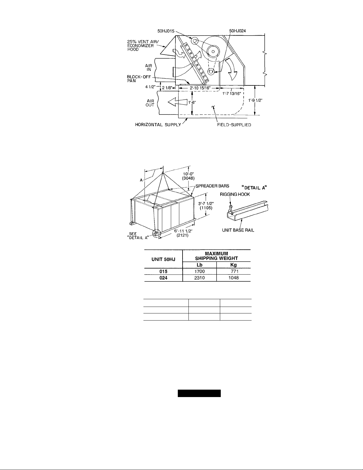
Step 2 — Rig and Place Unit — Inspect unit for
transportation damage. File any claim with transportation
agency. Keep unit upright, and do not drop. Use spreader
bars over unit to prevent sling or cable damage. Rollers
may be used to move unit across a roof. Level by using unit
frame as a reference; leveling tolerance is ± l/i6 in. per lin
ear ft in any direction. See Fig. 1 for additional leveling
tolerance information. Unit weight is shown in Table 1.
Four lifting holes are provided in ends of unit base rails
as shown in Fig. 3 Refer to rigging instructions on unit.
POSITIONING — Provide clearance around and above unit
for airflow, safety, and service access (Fig. 4).
Do not install unit in an indoor location. Do not locate
air inlets near exhaust vents or other sources of contam
inated air.
Although unit is weatherproof, guard against water from
higher level runoff and overhangs.
ROOF MOUNT — Check building codes for weight dis
tribution requirements.
Page 2

NOM. 5/4 X 4
(32) X (102)
TYP 4 PLC5
0“
COMPR
SECT
1 -6
(50P0900151 ONLY) lb4)
OPENING
(457) . ^ .
SUPPLY
CURB
PLAN VIEW OF ROOF CURB
- ___
RETURN
OPEN(NG
CURB
OUTLINE
g
___________
OF UNIT
A (1753)
.Ü
INSULATED PANE', FOR SIDE
SUHPLY AND RETURN
(50P09001S1 ONLY)
5'-3'
UNIT OPENINGS
-(’so/)
1 t
SUPPLY AIR RETURN AIR
SECT ION A-A
GASKET
(SUPPLIED
WITH CURB)
COUNTER FLASHING
ROOFING FELT
(FIELD SUPPLIED)
. CANT STRIP
(FIELD SUPPLIED)
RIGID INSULATION
(FIELD SUPPLIED)
-1 -4 5/16
(415)
(FIELD SUPPLIED)
•ROOFING material
(FIELD SUPPLIED)
OPTIONAL
SIDE 5UPPLT
(305)
ATTACH DUCT TO ROOF CURB
ACCESSORY
PACKAGE NO.
50PQ900221
50PQ900141
50PQ900151
CURB
HEIGHT
V-2"
(305)
2'-0"
(610)
2'-0"
(610)
DESCRIPTION
Standard Curb —
14" High
Standard Curb
for Units Requiring
High Installation
Horizontal Supply
and Return Curb
LEGEND
COMP SECT. — Compressor Section
NOTES:
1 Roof curb accessory is shipped unassembled.
2. Insulated panels, 1-in thick neoprene-coated,
IV2 lb density.
3 Dimensions in ( ) are in millimeters.
4 Direction of airflow.
5 Roof curb 16 gage steel.
O’-S 3/16*'
&
0 32)
NOTE: To prevent the hazard of stagnant water build-up in the drain
pan of the indoor-air section, unit can only be pitched as shown.
Fig. 1 — Roof Curb Details
I
Page 3
EVAPORATORFAN MOTOR
EVAPORATORFAN MOTOR
CURB (50P0900I5I)
TRANSITION DUCT
Fig. 2 — Horizontal Supply/Return Curb Details
DIMENSION A
UNIT 50HJ
015
024
Ft-in. mm
3-0 914
3-4’/2 1029
ÊJ
NOTES;
1. Dimensions in ( ) are in miilimeters
2 Refer to Tabie 1 for unit operating weights.
3. Remove boards at ends of unit and runners prior to rigging.
4 Rig by inserting hooks into unit base raiis as shown. Use corner
post from packaging to protect coii from damage. Use bumper
boards for spreader bars.
5 Weights do not inciude optionai economizer See Table 1 for econo
mizer weight.
6. Weights given are for aluminum evaporator coii plate fins and
copper condenser coii piate fins Weights of other metai combi
nations are listed in Table 1
A CAUTION
All panels must be in place when rigging.
Fig. 3 — Rigging Details
Page 4

CONTROL BOX
ACCESS
•25% AIR On
''ECONOMIZER HOOD
pO -3 7/16'
i (87)
C
SECTION A-A
■ }
0’-3"
(76)
O'-l"
1(102)
I
UNIT
50HJ
015 390
024 492
‘Weights are for unit only (with aluminum evaporator and condenser
coil fins) and do not include options or crating
Lb
A
Kg
177
233
CORNER WEIGHT*
B
Lb
Kg
243 110 322 146
232
511
C D
Lb
Kg
504 229
Lb
Kg
515 234
523 237
Fig. 4 — Base Unit Dimensions
DIMENSIONS
UNIT
50HJ
A
Ft-in. mm Ft-in. mm
015 3-0
024 3-4% 1035 3-7
LEGEND
914
B C
838 1-10 559
2-9
1092 1-8 508
Ft-in. mm
KO — Knockout
NOTES;
1 Dimensions in ( ) are in millimeters
2- ® Center of gravity.
Direction of airfloiw.
Ductwork to be attached to accessory roof curb only.
Minimum clearance:
a Rear; 7'-0" (2134) for coil removal. This dimension
can be reduced to 4'-0" (1219) if conditions permit
coil removal from the top
Left side: 4'-0" (1219) for proper condenser coil
airflow
Front' 4'-0" (1219) for control box access
Right side: 4'-0" (1219) for proper operation of damper
and power exhaust (if so equipped).
e. Top: 6'-0" (1829) to assure proper condenser fan
operation.
f. Local codes or jurisdiction may prevail.
With the exception of clearance for the condenser coil
and the damper/power exhaust as stated In note no 5, a
removable fence or barricade requires no clearance
Dimensions are from outside of corner post. Allow
O'-Vie" (8) on each side for top cover drip edge
i
Page 5

Table 1 — Physical Data
UNIT SIZE 50HJ
OPERATING WT (lb)
COMPRESSOR
REFRIGERANT
REFRIGERANT METERING DEVICE
CONDENSER COIL
CONDENSER FAN
EVAPORATOR COIL
EVAPORATOR FAN
HIGH-PRESSURE SWITCH
LOW-PRESSURE SWITCH
AIR INLET SCREENS
RETURN-AIR FILTERS (TYPE)
LEGEND
AI — Aluminum
Cu — Copper
'Evaporator coil fin material/condenser coil fin material.
tWeight of 14 in. roof curb.
"System 1 consists of the upper portion of condenser coil and intertwined evaporator coil, and
System 2 consists of the lower portion of the condenser coil and intertwined evaporator coil
NOTE: The 50HJ015 has adjustable pulleys The 50HJ024 has one set (2) of fixed pulleys
AI/AI*
Unit Al/Cu*
Cu/Cu*
Economizer
Roof Curbt
Number
Oil (oz)152
Charge (lb)** Sys 1, Sys 2
Upper Circuit
No. ...Length (in.)...iD/OD
Lower Circuit
No. ...Length (in.)...iD/OD
Rows
Fins/in.
Total Face Area (sq ft)
Nominal Cfm
Number...Diameter (in.)
Motor Hp (1075 Rpm)
Watts Input (Total)
Rows
Fins/in.
Total Face Area (sq ft)
Quantity...Size (in.)
Nominal Cfm
Maximum Allowable Rpm
Motor Pulley Pitch Diameter (in.)
Fan Pulley Pitch Diameter (in.)
Belt, Quantity...Type...Length (in.)
Factory Speed Setting (Rpm)
Motor Hp (Service Factor)
Motor Frame Size
Cutout (psig)
Reset (psig)_____________________
Cutout (psig)
Reset (psig)
Economizer, Quantity...Size (in.)
Quantity... Size (in.)
____________________
20.8,
6.. .25...0 055/0.125
6.. 25...0 055/0.125
6.. .25...0 055/0.125
Copper Tubes, Aluminum or Copper Plate Fins
13 6 Al or 12.4 Cu
18.9
12,000
2...26
1
2672
Copper Tubes, Aluminum or Copper Plate Fins
14.3 Al or 13.1 Cu
165
2.. 10 X 10
1 .V...41
2.. .20 X 20 X 2
3.. .16 X 20 X 2
2.. .16 X 25 X 2
Centrifugal, Fixed Pitch Belt Drive
5000
1550
3 4-4.4
6.0
1092
3 (1.15)
56
10% Efficient — 2-in Throwaway Fiberglass
R-22
I
Capillary Tubes
Propeller Type, Direct Drive
426
320
7
22
2 20 X 25 X 1
1 20 X 20 X 1
2030
2160
2270
110
200
16.25, 16.25
13. 25 .0.055/0.125
13...25.. 0.055/0 125
13.6 Al or 12.4 Cu
22 2
11,400
2 .26
1
3000
14.4 Al or 13.1 Cu
17.9
2...12 X 12
8000
1500
6.10
8.40
1. BX.. 51
1287
7V2 (1.15)
184T
4.. 20 X 20 X 2
4.. 16 X 20 X 2
Page 6
Step 3 — Field Fabricate Ductwork — Secure all
ducts to building structure. Use flexible duct connectors be
tween unit and ducts as required. Insulate and weatherproof
all external ductwork, joints, and roof openings with counter
flashing and mastic in accordance with applicable codes.
Ducts passing through an unconditioned space must be
insulated and covered with a vapor barrier.
The 50HJ units with electric heat require a 1-in. clear
ance for the first 24 in. of ductwork.
Outlet grilles must not lie directly below unit discharge.
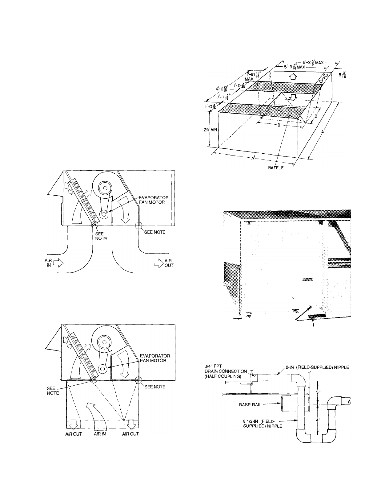
Step 4 — Make Unit Duct Connections - Unit
is shipped for through-the-bottom duct connections. Duct
work openings are shown in Fig. 5. Field-fabricated con
centric ductwork may be connected as shown in Fig. 6 and
7. Attach all ductwork to roof curb and roof curb basepans.
Refer to installation instructions shipped with accessory roof
curb for more information.
Step 5 — Trap Condensate Drain — See Fig. 4
and 8 for drain location. Plug is provided in drain hole and
must be removed when unit is operating. One V4-in. half
coupling is provided inside unit evaporator section for con
densate drain connection. An 8‘/2 in x %-in. diameter nip
ple and a 2-in. x %-in. diameter pipe nipple are coupled to
standard Y4-in. diameter elbows to provide a straight path
down through holes in unit base rails (see Fig. 9). A trap at
least 4-in. deep must be used.
i
Shaded area indicates block-off panels.
NOTE: Dimensions A, A' and B, B' are obtained from field-supplied
ceiling diffuser
Fig. 7 — Concentric Duct Details
NOTE. Do not drill in this area, as damage to basepan may resuit in
water leak.
Fig. 5 — Air Distribution — Through-the-Bottom
(50HJ024 Shown)
NOTE: Do not drill in this area, as damage to basepan may resuit in
water leak.
Fig. 6 - Concentric Duct Air Distribution
(50HJ024 Shown)
СОМЫЕстГоГ '-3/3" HOLES
Fig. 8 — Condensate Drain Details
Fig. 9 — Condensate Drain Piping Details
Page 7

Step 6 — Make Electrical Connections
FIELD POWER SUPPLY — Unit is factory wired for volt
age shown on nameplate.
When installing units, provide a disconnect, per NEC
(National Electrical Code) requirements, of adequate size
(Table 2).
All field wiring must comply with NEC and local
requirements.
Route power lines through control box access panel or
unit basepan (Fig. 4) to connections as shown on unit wir
ing diagram and Fig. 10.
Transformer no. 1 is wired for 230-v unit. If 208/230-v
unit is to be run with 208-v power supply, the transformer
must be rewired as follows;
1. Remove cap from red (208 v) wire.
2. Remove cap from orange (230 v) spliced wire.
3. Replace orange wire with red wire
4. Recap both wires.
IMPORTANT; BE CERTAIN UNUSED WIRES
ARE CAPPED. Failure to do so may damage the
transformers.
Operating voltage to compressor must be within voltage
range indicated on unit nameplate. On 3-phase units, volt
ages between phases must be balanced within 2% and the
current must be balanced within 10%.
Use the following formula to determine the percentage of
voltage imbalance.
Percentage of Voltage Imbalance
— 100 X voltage deviation from average voltage
average voltage
Example; Supply voltage is 460-3-60.
AB =452 V
BC =464 V
AC =455 V
Average Voltage =
Determine maximum deviation from average voltage.
(AB) 457 -452 =5 v
(BC) 464 -457 =7 V
(AC) 457 -455 =2 v
Maximum deviation is 7 v.
Determine the percentage of voltage imbalance;
Percentage of Voltage Imbalance = 100 x -
452 +464 +455
1371
“ 3
= 457
7
TB1 MAXIMUM WIRE SIZE
UNIT 50HJ
015 350 kcmil
024 350 kcmil
EQUIP — Equipment
GND — Ground
kcmil — Thousand Circular Mils
NEC — National Electrical Code
TB
208/230 460 575
— Terminal Block
VOLTAGE
2/0 2/0
2/0 2/0
LEGEND
Fig. 10 — Field Power Wiring Connections
FIELD CONTROL WIRING - Install a Carrier-approved
accessory thermostat assembly according to the installation
instructions included with the accessory. Locate thermostat
assembly on a solid wall in the conditioned space to sense
average temperature.
Route thermostat cable or equivalent single leads of
no. 18 AWG (American Wire Gage) colored wire from
subbase terminals through conduit in unit to low-voltage
connections as shown on unit label wiring diagram and in
Fig. 11.
NOTE; For wire runs up to 50 ft, use no. 18 AWG insu
lated wire (35 C minimum). For 50 to 75 ft, use no. 16
AWG insulated wire (35 C minimum). For over 75 ft, use
no. 14 AWG insulated wire (35 C minimum). All wire larger
than no. 18 AWG cannot be directly connected to the ther
mostat and will require a junction box and splice at the
thermostat.
Set heat anticipator settings as indicated in Table 3. Set
tings may be changed slightly to provide a greater degree of
comfort for a particular installation.
Refer to accessory remote control instructions as
required.
= 1.53%
This amount of phase imbalance is satisfactory as it is
below the maximum allowable 2%.
IMPORTANT; If the supply voltage phase imbal
ance is more than 2%, contact your local electric util
ity company immediately.
Unit failure as a result of operation on improper line volt
age or excessive phase imbalance constitutes abuse and may
cause damage to electrical components.
THERMOSTAT ASSEMBLY
Fig. 11 — Field Control Thermostat Wiring
Page 8

Table 2 — Electrical Data
UNIT
50HJ
015
024
FLA HACR LRA MCA MOCP NEC RLA -
•Heater capacity (kW) is based on heater voitage of 208 v, 240 v, 480 v and
575 V. if power distribution voltage to unit varies from rated heater voltage,
heater kW will vary accordingly This is the maximum size permissible; smaller
fuse size may be used where conditions permit
tFuse or HACR circuit breaker
"Heaters are field installed only
V-PH-HZ
208/230-3-60
460-3-60
575-3-60
208/230-3-60 187
460-3-60
575-3-60 518
Full Load Amps
Heating, Air Conditioning and Refrigeration
Looked Rotor Amps
Minimum Circuit Amps
Maximum Overcurrent Protection
Nationai Eiectrioai Code
Rated Load Amps
VOLTAGE
RANGE
Min Max
187 253
414 508 22 1
632
518
253
414 508
632
LEGEND
COMPRESSOR
No. 1 No. 2
RLA LRA RLA
49 3 191
86
179
69
43 9 170
199
15 9 62
77
43 9
199
159
- -
- -
- -
170
CONDENSER
FAN MOTOR
LRA Qty
77
62 2
2
2
2
2
2
EVAPORATOR
FAN MOTOR
FLA
77 3 105
33 3
26 3
54
I'k
(ea)
27
7'/г 11 0
(ea)
34
7'M
(ea)
NOTES
1 In compliance with NEC requirements for multimotor and combination load
equipment (refer to NEC Articles 430 and 440), the overcurrent protective
device for the unit shall be fuse or HACR breaker The Canadian units may
be fuse or circuit breaker
MCA calculation for units with electric heaters over 50 kW
FLA
Hp
48
3 9
24 2/22 0
90
= (1.25 X IFM amps) + (1 00 x heater FLA).
ACCESSORY/OPTIONAL
ELECTRIC HEATERS*
FLA kW MCA^
39/ 45
72/ 82
117/135
18
39
66
37 37
72/ 82
117/135
156/180**
39
66
96**
14/19
26/34
42/56
26/34
42/56
56/75**
-
15
32
55
32
55
80**
-
103/116
159/148
134/132
134/132
177/163
186/208**
POWER SUPPLY
88/ 88
88/ 88
100/100
100/100
110/125
175/175
39
39
55
72
32
52
175/175
175/175
200/175
200/225**
62
62
80
110**
52 60
MOCPt
110**
Warnock Hersey
45
45
60
80
35
60
80
80
90
Table 3 — Heat Anticipator Settings
UNIT
50HJ
U1 b
50HJ
024
VOLTAGES
208/230
460
575
208/230,575-3-60 42/52
460-3-60
kW
14/17 40
26/31 40
42/52
15
30 40 40
51
37 40
26/31
56/69
30
51
73
STAGE 1
66 40
40
40 66
40
.66
66
40
40 66
66
STAGE 2
_
40
_
.66
66
40
66
40
66
Step 7 — Make Outdoor-Air Inlet Adjustments
MANUAL OUTDOOR-AIR DAMPER - All units
(except those equipped with a factory-installed economizer)
have a manual outdoor-air damper to provide ventilation
air. Damper can be preset to admit up to 25% outdoor air
into retum-air compartment. To adjust, loosen securing screws
and move damper to desired setting Then retighten screws
to .secure damper (Fig. 12).
OPTIONAL FACTORY-INSTALLED ECONOMIZER
Economizer Motor Control Module (Fig, 13-15) — Set to
the "D" setting (Fig. 14) The control module is located on
the economizer motor. See Fig, 13 and 15.
Damper Vent Position Setting
1. Set fan switch at ON position (continuous fan operation)
and close night switch if used.
2. Set system selector switch to OFF position.
3. Turn adjustment screw slowly until dampers assume de
sired vent position. Do not manually operate econo
mizer motor since damage to motor will result.
NOTE; Refer to accessory installation instructions in
cluded with the field-installed economizer for installation
information. Also see Accessory Field-Installed Econo
mizer Adjustment section on page 10.
Step 8 — Install Outdoor-Air Hood — The same
type of factory-installed hood is used on units with 25% air
ventilation and units with an economizer.
NOTE; The hood top panel, upper and lower filter retain
ers, hood drain pan, baffle (024 only), and filter support
bracket are secured opposite the condenser end of the unit.
The screens, hood side panels, remaining section of filter
support bracket, seal strip, and all other hardware are in a
package located inside the return-air filter access panel
(Fig. 16)
1. Attach seal strip to upper filter retainer. See Fig. 17.
2. Assemble hood top panel and side panels, upper filter
retainer, and hood drain pan (Fig. 18)
3. Secure lower filter retainer and long piece of filter sup
port bracket to unit. See Fig. 18. Leave screws on 024
units loose
4. 50HJ024 Units Only; Slide baffle behind lower filter re
tainer and tighten screws.
5. Loosen sheet metal screws for base unit top panel lo
cated above outdoor-air inlet opening.
25% ADJUSTABLE
AIR DAMPER
BASE
■ UNIT
SECURING SCREWS
Fig. 12 — 25% Outdoor-Air Section Details
t
I
Page 9

COOLING
LOCKOUT
SWITCH
ECONOMIZER
MOTOR
ECONOMIZER
CONTROL
MODULE
FILTERS-
ECONOMIZER
DAMPER
ASSEMBLY
msf$
Fig. 13 — Economizer Damper Assembly — End View
6. Match notches in hood top panel to unit top panel screws
Insert hood flange between unit top panel flange and unit.
Tighten screws.
7 Insert outdoor-air inlet screens and spacer in channel cre
ated by lower filter retainer and filter support bracket.
8. Attach remaining shorter section section of filter sup
port bracket.
CHANGEOVER
SET POINT
MINIMUM
DAMPER
- POSITION
SETTING
LED LIGHTS UP
TO INDICATE
-OUTDOOR AIR
IS SUITABLE FOR
FREE COOLING
Fig. 14 — Economizer Control Module
ECONOMIZER MOTOR
Fig. 16 — Outdoor-Air Hood
Component Location
Fig. 17 — Seal Strip Location
(Air Hood Cross-Sectional View)
HOOD DRAIN
PAN
Fig. 15 — Economizer Control Module Location
Fig. 18 - Outdoor-Air Hood Details
Page 10

START-UP
Use the following information and Start-Up Checklist on
page CL-1 to check out unit PRIOR to start-up.
Unit Preparation — Check that unit has been installed
in accordance with these installation instructions and all
applicable codes.
Compressor Mounting — Loosen compressor hold
down bolts until sideways movement of the washer
under each holddown bolt head can be obtained. Do not
loosen completely, as bolts are self-locking and will main
tain adjustment.
Internal Wiring — Check all electrical connections in
unit control boxes; tighten as required.
Refrigerant Service Ports and Valves — Each 50HJ
unit has 2 Schrader-type service ports per circuit; one on
the suction line and one on the liquid line. Be sure that the
caps on the ports are tight. The units also have 2 service
valves per circuit; one on the suction line and one on the
discharge line. Be sure all valves are open.
Crankcase Heaters —
as there is power to unit.
IMPORTANT; Unit power must be on for 24 hours
prior to start-up. Otherwise, damage to compressor
may result.
Heaters are energized as long
Evaporator Fan — Fan belt and pulleys are factory in
stalled. Remove tape from the fan pulley and adjust pulleys
on 50HJ015 units as required. See Evaporator-Fan Perfor
mance Adjustment section on page 12. See Table 4 for Air
Quantity Limits. See Tables 5, 6A, and 6B for Fan Perfor
mance data. Be sure that fans rotate in the proper direction.
See Table 7 for Static Pressure Drops for accessories and
options. To alter fan performance, see Evaporator-Fan Per
formance Adjustment sections, pages 12 and 13.
Table 4 — Air Quantity Limits
UNIT 50HJ MINIMUM CFM
015 3750 6,250
024
6000 10,000
MAXIMUM CFM
Condenser Fans and Motors — Fans and motors
are factory set. Refer to Service, Condenser-Fan Adjust
ment section as required.
Return-Air Filters — Check that correct filters are
installed in filter tracks. See Table 1. Do not operate unit
without return-air filters.
Outdoor-Air Inlet Screens — Outdoor-air inlet screens
must be in place before operating unit.
Accessory Field-Installed Economizer Adjust
ment — Remove filter access panel. Check that outdoor-
air damper is closed and return-air damper is open.
Economizer operation and adjustment is described in
Start-Up, Base Unit Operation; and Service, Economizer
Adjustment sections, respectively.
Base Unit Operation
COOLING, UNITS WITHOUT ECONOMIZER - When
thermostat calls for cooling, terminals G and Y1 are ener
gized. The indoor (evaporator) fan contactor (IFC) and com
pressor contactor no. 1 (Cl) are energized and evaporatorfan motor, compressor no. 1 (024) or unloaded compressor
(015), and condenser fans start. The condenser-fan motors
run continuously while unit is cooling. If the thermostat calls
for a second stage of cooling by energizing Y2, compressor
contactor no. 2 (C2) is energized and compressor no. 2 starts
(024), or compressor no. 1 runs fully loaded (015).
A freeze protection thermostat (FPT) is located on the
evaporator coil. It detects frost buildup and turns off the
compressors, allowing the coil to clear. Once frost has melted,
the compressors can be reenergized by resetting the
thermostat.
HEATING, UNITS WITHOUT ECONOMIZER (If Acces
sory or Optional Heater is Installed) — Upon a call for
heating through terminal Wl, IFC and heater contactor
no. 1 (HCl) are energized. On units equipped for 2 stages
of heat, when additional heat is needed, HC2 is energized
through W2.
COOLING, UNITS WITH ECONOMIZER - Upon a call
for cooling, when outdoor ambient temperature is above the
outdoor-air temperature control setting, the evaporator and
condenser fans and compressor energize. The economizer
damper moves to VENT position.
Upon a first-stage call for cooling, when outdoor ambi
ent temperature is below the temperature control setting,
the evaporator fan starts and economizer damper modulates
to maintain mixed-air temperature. The compressor(s) re
mains off.
Upon a second-stage call for cooling, compressor no 1
(024) or unloaded compressor (015) is energized and me
chanical cooling is integrated with economizer cooling Com
pressor no. 2 (024 only) is locked out. If the outdoor-air
temperature is below 50 F, a cooling lockout switch
prevents the compressor(s) from running.
When supply-air temperature drops below a fixed set point,
the economizer damper modulates to maintain the temper
ature at the fixed set point.
HEATING, UNITS WITH ECONOMIZER (If Accessory
or Optional Heater is Installed) — The outdoor air damper
stays at VENT position while the evaporator fan is operat
ing Upon a call for heating through terminal Wl, the in
door (evaporator) fan contactor (IFC) and heater contactor
no. 1 (HCl) are energized. On units equipped for 2 stages
of heat, when additional heat is needed, HC2 is energized
through W2.
10
Page 11

Ф
Table 5 — Fan Performance Data, 50HJ015 Units
AIRFLOW
(Cfm)
3750 732
4000 764
4250 797
4500
4750 865 1226 965 1421 1056
5000 900
5250 935
5500
5750 1007
6000 1044
6250
0.2 0.4 0.6 0.8
835 949
1101
1252
2007
2238
2487
2753
Rpm Watts
977
1110
1001 1261
1430
1028
1607
1084 1803
2007
2229 1221
1142
2469
1173
2718
1205
2993
1236
Rpm
Watts
684 848
799
933
831 1075
1403
1590
1794 1060
971
2016
2256
1080 2513
Rpm Watts
876 968 974
904
934
996 1599
1028 1794 1112
1093
1126
1159
LEGEND
Watts — Input Watts to Motor
NOTES:
1, Factory shipped fan speed is 1092 rpm. The range of the stand
ard evaporator-fan motor is 978 to 1285 rpm. Other rpms may
require a field-supplied drive.
2 Static pressure iosses (i.e., economizer, eiectric heater) must be
added to external static pressure before entering Fan Perfor
mance table.
3. To convert watts to bhp, use the following equation:
„Watts X motor efficiency
^ 746
EXTERNAL STATIC PRESSURE (in. wg)
Rpm Watts Rpm Watts
1041
1119
1065 1261
1412 1170 1581
1089
1113 1581
1767
1139
1166 1980
1193 2202
2433 1294 2629
2682 1321 2895
1249
1277 2948
Table 6A — Fan Performance Data — 50HJ024, 208/230-V and 575-V Units
1.0
Rpm Watts
1124
1146 1412
1193 1750
1217
1241
1266 2371 1338
1270
1945
2149
1194 1430
1221 1572
1244 1741
1267
1290
1314 2336
1362 2806
Motor efficiency: Horsepower — Maximum Continuous Watts:
4 Interpolation is permissible Do not extrapolate.
5. Fan performance is based on wet coils, clean filters, and casing
losses.
6. Extensive motor and drive testing on these units ensures that
the full range of the motor can be utilized with confidence. Using
your fan motors up to the watts rating shown will not result in nui
sance tripping or premature motor failure Unit warranty will not
be affected.
1.2 1.4
Rpm
1247 1599
1284 1750 1331
1312 1909 1369 2096
1918
1335
2123
1358
1381 2522 1444 2709
2567
1405 2762
1429
Watts Rpm
2096
2300 1422 2487
3011
1.6
Watts Rpm Watts
1274 1767
1927
2282 1451 2478
1398
2948
1468
— —
0 84 3 hp - 3065
1.8
~ — —
1357
2105
1413 2282
1480 2682
2904
1504
— —
— —
2.0
Rpm Watts
—
—
2877
—
— —
— —
—
—
1440 2469
1493 2673
1531
AIRFLOW
(Cfm)
6,000
6,500
7,000
7,500
8,000
8,500
9,000
9,500
10,000
0.2 0.4
Rpm Watts
702
747
792 2138
838 2571 918
885 3060
932 3610 1005
980 4223 1050
1028 4904 1096
1077
Rpm Watts Rpm Watts Rpm Watts Rpm Watts Rpm
1428
796
1757
835
877 2476
962 3440 1036 3822 1105
1141
5655
0.6
1723 884 2025 965
2073 919
2929 996 3290 1067
4011 1077
4647
5350 1162 5796 1224
6123 1205 6591 1266
957
1119
2394
2816
4414
5071
EXTERNAL STATIC PRESSURE (in. wg)
0.8 1.0
2339
997
2725 1070
1031 3165
3658
4209
1143 4821 1206 5234 1266
1183
5498
6243
7059
LEGEND
Watts — Input Watts to Motor
NOTES-
1. Factory shipped fan speed is 1287 rpm Other rpms may require
a field-supplied drive.
2. Static pressure losses (i e., economizer, electric heater) must be
added to external static pressure before entering Fan Perfor
mance table
3. To convert watts to bhp, use the following equation:
„Watts X motor efficiency
^ 746
Table 6B — Fan Performance Data — 50HJ024, 460-V Units
AIRFLOW
(Cfm)
6,000
6,500
7,000 792
7,500 838
8,000 885
8,500
9,000 980
9,500 1028
10,000
0.2
Watts Rpm Watts Rpm
Rpm
702 1428 796 1723
747 1757
2138
2571 918 2929
3060 962 3440
932 3610 1005 4011
4223 1050
4904
1077 5655
0.4 0.6
835
2073
877
2476
4647 1119
1096 5350
1141
6123
Watts Rpm Watts
884 2025
919
2394
957 2816
996 3290 1067
1036
3822 1105 4209 1170
1077
4414 1143 4821 1206
5071
1162 5796 1224
1205 6591
LEGEND
Watts — Input Watts to Motor
NOTES:
1 Factory shipped fan speed is 1287 rpm. Other rpms may require
a fieid-supplied drive.
2. Static pressure losses (i.e , economizer, electric heater) must be
added to external static pressure before entering Fan Perfor
mance table
3 To convert watts to bhp, use the following equation:
_ Watts X motor efficiency
Bhp
746
EXTERNAL STATIC PRESSURE (in. wg)
0.8
965 2339
997 2725
3165
1031
3658 1135
1183 5498
6243 1283
1266 7059 1323 7531 1378
1.2 1.3 1.4 1.6
Watts
Rpm Watts
1041 2669 1115 3018
3069 1140 3429 1174 3617 1208 3805
1102 3525 1169 3898 1201
1135 4035 1199
1170 4604 1232 5008 1262 5180 1292 5422 1350
1244
5930 1302
1283 6695 1340
1323 7531
Motor efficiency: Horsepower — Maximum Continuous Watts:
4 Interpolation is permissible Do not extrapolate.
5. Fan performance is based on wet coils, clean filters, and casing
losses.
6. Extensive motor and drive testing on these units ensures that
the full range of the motor can be utilized with confidence. Using
your fan motors up to the watts rating shown will not result in nui
sance tripping or premature motor failure. Unit warranty will not
be affected.
1.0
Rpm Watts Rpm Watts Rpm Watts Rpm
1041 2669 1115 3018
3069 1140 3429 1174
1070
1102 3525 1169 3898
4035
4604 1232 5008 1262
5234
1244 5930 1302 6369
6695
1.2
1199
1266
1340
1150
4422
1230
5655
1295
6369
1330
7152
1367 7384 1394 7616
0.87 71/2 hp-7915
1.3
1150 3201 1186
1201 4091 1233
4422
1230 4622
5655 1295
1330 6592
7152 1367 7384 1394 7616
8007 1404
Rpm
3201 1186 3385 1255
1233 4285 1296
4091
4622 1262 4822
1324
5870
6592 1359 6816 1413 7270 1466 7735
1.4
3617 1208
1262 4822 1322
1292 5422 1350
5180
1324 6085 1380
5870
1359 6816 1413
8248 1431
Rpm Watts
Watts
1274
1322
6085 1380 6524
— — —
Rpm
Watts
3385
1255
3805 1274 4198
4285
1296
1447 8088
8489
— — —
Motor efficiency: Horsepower — Maximum Continuous Watts
0 87 7V2 hp - 8640
4 Interpolation is permissible. Do not extrapolate.
5 Fan performance is based on wet coils, clean filters, and casing
losses.
6. Extensive motor and drive testing on these units ensures that
the fuli range of the motor can be utilized with confidence. Using
your fan motors up to the watts rating shown will not result in nui
sance tripping or premature motor faiiure. Unit warranty wili not
be affected.
11
1.8
Rpm
3771
1322 4175
4198
1338
4687
1358
5235 1381 5662
5847
1407 6286
1435
1.6 1.8
Watts
Rpm
3771
1322 4175
1338 4609
4687
1358 5106
5235
1381
5847
1407
6524
1435 6975
7270
1466
—
Watts
4609
5106
6975
—
Watts
5662
6286
7735
—
—
Page 12

Table 7 — Accessory/FlOP Static Pressure Drop* (in. wg)
UNIT
50HJ
015 460-3-60
024 460-3-60
Flop — Factory-Installed Option
*The static pressure must be added to external static pressure The sum and
the evaporator entering air cfm should then be used in conjunction writh the
Fan Performance tabie to determine biower rpm and watts
UNIT
VOLTAGE
208/230-3-60
575-3-60
208/230-3-60
575-3-60
CFM
4.000
5.000
6.000
7,200
4.000
5.000
6.000
7,200
4.000
5.000
6.000
7,200
6,000
7,200
9,000
10,000
6,000
7,200
9,000
10,000
6,000
7,200
9,000
10,000
SERVICE
ELECTRIC HEATERS
0 05 (14-34) 0 06 (42) 0 07 (56'
0.07(14-34) 0.08(42 0.10(56'
0 09 (14-34) 0 12 42 0.15 56
0 09 (26/34) 0 12 (42/56) 0 15 (56/75)
oil 26/34 016 42/56 0 20 56/75
0 15 26/34 0 19 42/56 0 24 56/75
0.17 26/34 0.21 (42/56) 0.26 (56/75
0.09 (32) 0.12 (55) 0.15 (80)
oil 32 0.15 (55 0 20 80
015 (32 0 19 55 0 24 (80
0.17 32 0 21 55) 0.26(80
NOTE: Heaters are rated at 208/240 v, 480 v, and 575 v
(kW)
0 05 (15,32) 0.06 (55
0 07 15,32 0 08 55
0 09 (15,32) 012 (55,
0.06 (37)
0 08 37)
0 12 37
0 15 37
ECONOMIZER
0 03
0 05
0.07
0 09
0 03
0 05
0.07
0 09
0 03
0.05
0 07
0 09
0 07
0 09
0.11
0 12
0 07
0 09
0.11
0.12
0 07
0 09
0.11
0 12
(
A WARNING
Before performing service or maintenance operations
on unit, turn off main power switch to unit. Turn off
accessory heater power switch if applicable. Electrical
shock could cause personal injury.
Cleaning — Inspect unit interior at beginning of each
heating and cooling season and as operating conditions re
quire. Remove unit top panel and/or side panels for access
to unit interior.
EVAPORATOR COIL — Clean as required with a com
mercial coil cleaner.
CONDENSER COIL — Clean condenser coil annually and
as required by location and outdoor-air conditions. Inspect
coil monthly — clean as required.
CONDENSATE DRAIN — Check and clean each year at
start of cooling season.
FILTERS — Clean or replace at start of each heating and
cooling season, or more often if operating conditions re
quire. Refer to Table 1 for type and size.
OUTDOOR-AIR INLET SCREENS — Clean screens with
steam or hot water and a mild detergent. Do not use dis
posable filters in place of screens.
Lubrication
COMPRESSORS -- Each compressor is charged with cor
rect amount of oil at the factory. Observe the oil level in
the sight glass at start-up. If unit oil level is below sight
glass, add oil until level is approximately V4 sight glass.
FAN SHAFT BEARINGS The bearings are of the pil
low block type and have grease fittings. The bearing oppo
site the motor end has an extended tube line so it can be
lubricated from the motor side. Lubricate the bearings twice
annually.
Typical lubricants are given below:
MANUFACTURER LUBRICANT
Texaco Regal AFB-2*
Mobil Mobilplex EP No. 1
Sunoco Prestige 42
Texaco
'Preferred lubricant because it contains rust and oxidation inhibitors
Multifak 2
CONDENSER AND EVAPORATOR-FAN MOTOR BEAR
INGS — The condenser and evaporator-fan motors have
permanently-sealed bearings, so no field lubrication is
necessary.
Evaporator Fan, 50HJ015 Units
PERFORMANCE ADJUSTMENT - Fan motor pulleys on
the 50HJ015 units are factory set for speed shown in
Table 1.
To change fan speeds:
1. Shut off unit power supply.
2. Loosen belt by loosening fan motor mounting plate nuts.
3. Loosen movable-pulley flange setscrew (see Fig. 19).
4. Screw movable flange toward fixed flange to increase
speed and away from fixed flange to deccrease speed.
Increasing fan speed increases load on motor. Do not
exceed maximum speed specified in Table 1.
5. Set movable flange at nearest key way of pulley hub and
tighten setscrew. (See Table 1 for speed change for each
full turn of pulley flange.)
To align fan and motor pulleys:
1. Loosen fan pulley setscrews.
2. Slide fan pulley along fan shaft.
3. Make angular alignment by loosening motor from mount
ing plate.
SERVICE AND REPLACEMENT (see Fig. 20)
NOTE: To remove belts only, follow Steps 1-7.
1. Remove filter and supply-air section panels.
2. Remove unit to cover.
3. Remove coil guard,
4. Loosen screws A and B on both sides of motor mount
assembly.
5. Loosen screw C.
6. Rotate motor mount assembly (with motor attached) as
far as possible away from evaporator coil.
7. Remove belt.
12
Page 13

Rotate motor mount assembly back past original posi
tion toward evaporator coil.
Remove motor mounting nuts D and E (both sides).
9.
Lift motor up through top of unit.
10.
Reverse above procedure to reinstall motor.
11
12,
Check and adjust belt tension as necessary.
Fig. 19 — Evaporator-Fan Pulley Alignment
and Adjustment
Evaporator Fan, 50HJ024 Units
PERFORMANCE ADJUSTMENT - The 50HJ024 unit has
fixed pulleys. Fan speed can be adjusted (if necessary) only
by changing the pulley(s) and belt. See Table 8 for alter
nate drive selection.
To align fan and motor pulleys (see Fig. 19):
1. Loosen fan pulley setscrews.
2. Slide fan pulley along fan shaft.
3. Make angular alignment by loosening motor from mount
ing plate.
SERVICE AND REPLACEMENT (See Fig. 21) - The
50HJ024 unit uses a fan motor mounting system that fea
tures a slide-out motor mounting plate. To replace or serv
ice the motor, slide out the bracket.
1. Remove the evaporator-fan access panel and the heat
ing control access panel.
2. Remove the center post (located between the evapora
tor fan and heating control access panels) and all screws
securing it
3. Loosen nuts on the two carriage bolts in the motor mount
ing base.
Using jacking bolt under motor base, raise motor to
4.
top of slide and remove belt. Secure motor in this po
sition by tightening the nuts on the carriage bolts.
5.
Remove the belt drive.
6. Remove Jacking bolt and tapped jacking bolt plate.
7. Remove the 2 screws that secure the motor mounting
plate to the motor support channel.
8. Remove the 3 screws from the end of the motor sup
port channel that interfere with the motor slide path,
9 Slide out the motor and motor mounting plate,
10. Disconnect wiring connections and remove the 4 mount
ing bolts.
11. Remove the motor.
12. To install the new motor, reverse Steps 1-11.
Fig. 20 — 50HJ015 Evaporator-Fan Motor Section
NOTE; A 3V2-in, bolt and threaded plate are included in the instalier’s packet. They can be added to the motor support channel below
the motor mounting plate to aid in raising the motor.
Fig. 21 — 50HJ024 Evaporator-Fan Motor Section
13
Page 14

Table 8 — Alternate Drive Components Table, 50HJ024
UNIT
50HJ
024
MPTA — Mechanical Power Transmission Association
RMA — Rubber Manufacturers’ Association
‘Datum dimension is equal to the old pitch diameter per RMA/MPTA
Standard IP20-1977. To convert to new pitch diameter per RMA/
MOTOR
HP
7V2 Field
71/2
Vh
7'M Field
DRIVE
SOURCE
Field
Factory 1287
LEGEND
FAN
RPM
1181
1244
1379
MOTOR
SHEAVE DATUM
DIMENSION*
(in.)
5.6
5.9
6 1
6.6
MOTOR
SHEAVE
PART NO.t
BK62 8.4
BK65 8,4
BK67 84
BK72 8.4
MPTA Standard IP20-1988, add 0.3 in. to the sheave datum
dimension.
tPart numbers for motor sheave, blower sheave, and belt are Brown
ing Catalog part numbers. The motor sheaves have Browning fixed
bore sheaves supplied with factory drive package.
BLOWER
SHEAVE DATUM
DIMENSION*
(in.)
BLOWER
SHEAVE
PART NO.t
BK90
BK90
BK90 BX51
BK90
PART NO.t
BELT
BX50
BX51
BX52
i
Belt Tension Adjustment — To adjust belt tension:
1. Loosen fan motor bolts.
2. a. 015 units:
Move motor mounting plate up or down for proper
belt tension ('/2 in, deflection with one finger),
b. 024 units;
Turn motor jacking bolt to move motor mounting plate
up or down for proper belt tension (Ys in. deflection
at midspan with one finger [9 lb force]).
3. Tighten nuts.
4. Adjust bolts and nut on mounting plate to secure motor
in fixed position.
Condenser-Fan Adjustment {Fig. 22)
1. Shut off unit power supply.
2. Remove fan top-grille assembly and loosen fan hub screws.
3. Adjust fan height on unit, using a straightedge placed
across the fan orifice.
4. Tighten setscrews and replace rubber hubcap to prevent
hub from rusting to motor shaft.
5. Fill hub recess with permagum if rubber hubcap is
missing.
Economizer Adjustment — Refer to Tables 9 and
10 for economizer checkout procedures. Make certain the
outdoor-air damper is fully closed and the return-air damper
is fully open before completing the following steps.
1. Turn on power to the unit.
2. Turn the thermostat fan switch to the ON position. The
damper will go to the vent position.
3. Adjust the vent position with the minimum position ad
justment on the economizer control module. See
Fig. 14.
4. Set the system selector switch to COOL position and
set the cooling temperature selector to its lowest
setting.
NOTE: The cooling mode may also be simulated by remov
ing the thermostat wires from terminals Y1 and Y2 and in
stalling a jumper between terminals R and Y1. Refer to unit
label diagram for terminal locations.
5. Set the outdoor-air thermostat (OAT) located in the econo
mizer section of the unit to 75 F.
6. If the outdoor temperature is below 75 F, the econo
mizer will control the mixed air with the mixed-air sen
sor. If the outdoor air is above 75 F, place a jumper
around the contacts of the OAT
7. Jumper terminal T to terminal T1 on the module (see
Fig. 14). The economizer will go to the full open
position. The outdoor-air damper will go to the full open
position, and the return-air damper will go to the full
closed position.
8. Adjust mechanical linkage, if necessary, for correct po
sitioning. It may be necessary to remove the filters to
adjust the linkage.
9. Remove the jumper from around the contacts of the
OAT if installed in Step 6. Remove the jumper from
terminals T and T1 installed in Step 7.
10. If the cooling mode was simulated to operate the unit
in Step 4, remove the jumper and reconnect the ther
mostat wires to terminals Y1 and Y2.
Power Failure — Dampers have a spring return In event
of power failure, dampers will return to fully closed posi
tion until power is restored. Do not manually operate damper
motor.
Refrigerant Charge — Amount of refrigerant charge
is listed on unit nameplate and in Table 1. Refer to Carrier
GTAC II; Module 5; Charging, Recovery, Recycling, and
Reclamation section for charging methods and procedures.
Unit panels must be in place when unit is operating dur
ing charging procedure.
Fig. 22 — Condenser-Fan Adjustment
NO CHARGE — Use standard evacuating techniques.
After evacuating system, weigh in the specified amount of
refrigerant (refer to Table 1).
LOW CHARGE COOLING - Using appropriate cooling
charging chart (see Fig. 23 and 24), add refrigerant until
conditions of the chart are met. Note that charging charts
are different from those normally used. Charts are based on
charging units to correct superheat for various operating con
ditions. An accurate pressure gage and temperature sensing
device are required. Connect temperature sensing device to
service port on suction line and insulate it so that outdoor
ambient temperature does not affect reading. Indoor-air cfm
must be within normal operating range of unit.
14
Page 15

TEST PROCEDURE RESULTS
A Disconnect
factory-installed
resistor from
terminals Sr and +
1 LED (light-emitting diode)
should be on
2. Motor drives toward open
OUTDOOR
TEMP (F)
Table 10 — High and Low Outdoor-Air
40 50 60
SUCTION LINE TEMP (FÌ
Temperature Simulation
TEST PROCEDURE RESULTS
A Reconnect factory-
installed 800 ohm resistor
between terminals
Sr and +
i
B. Connect 1200 ohm
checkout resistor
between terminals
So and +.
C. Turn set point potentiom
eter to position A
D. Turn set point potentiom
eter to position D
E Disconnect 1200 ohm
checkout resistor
Low outdoor-air temperature
test results:
1 LED (light-emitting diode)
should be on
2 Motor drives toward open
High outdoor-air temperature
test results
1 LED should be off
2 Motor drives toward closed.
Fig. 23 — Cooling Charging Chart — 50HJ015
OUTDOOR TEMP
-
90-
Î50-
F
15
05
95
55
85
75
45
35
65
TO USE COOLING CHARGING CHART - Take out
door ambient temperature and read the suction pressure gage.
Refer to appropriate chart to determine correct suction tem
perature. If suction temperature is high, add refrigerant. If
suction temperature is low, carefully reclaim some of the
charge. Recheck suction pressure as charge is adjusted
Filter Drier — Replace whenever refrigerant system is
30-
20
30 40 SO 60
SUCTION LINE TEMPERATURE CF)
-
BOTH CONDENSER FANS RUNNING
LU Li_LLLL 1TJ__
ONE CONDENSER FAN RUNNING
exposed to atmosphere.
Fig. 24 — Cooling Charging Chart — 50HJ024
15
Page 16

Protective Devices
COMPRESSOR PROTECTION
Overcurrent — Each compressor has one manual reset, cal
ibrated trip, magnetic circuit breaker. Do not bypass con
nections or increase the size of the circuit breaker to correct
trouble. Determine the cause and correct it before resetting
the breaker.
Overtemperature — Each compressor has an internal pro
tector to protect it against excessively high discharge gas
temperatures.
Crankcase Heaters — Each compressor has 125-watt crank
case heaters to prevent absorption of liquid refrigerant by
oil in the crankcase when the compressor is idle. Since power
for the crankcase heaters is drawn from the unit incoming
power, main unit power must be on for the heaters to be
energized.
EVAPORATOR-FAN MOTOR PROTECTION - A man
ual reset, calibrated trip, magnetic circuit breaker protects
against overcurrent. Do not bypass connections or increase
the size of the breaker to correct trouble. Determine the
cause and correct it before resetting the breaker.
CONDENSER-FAN MOTOR PROTECTION - Each
condenser-fan motor is internally protected against over
temperature.
HIGH- AND LOW-PRESSURE SWITCHES - If either
switch trips, or if the compressor overtemperature switch
activates, that refrigerant circuit will be automatically locked
out by the CLO To reset, manually move the thermostat
setting
FREEZE PROTECTION THERMOSTAT (FPT) - An
FPT is located on the evaporator coil. It detects frost
buildup and turns off the compressor, allowing the coil to
clear. Once the frost has melted, the compressor can be
reenergized by resetting the CLO from the thermostat.
IMPORTANT; After a prolonged shutdown or serv
ice job, energize the crankcase heaters for 24 hours
before starting the compressors
Compressor Lockout— If any of the safeties (high- or lowpressure, freeze protection thermostat, compressor internal
thermostat) trip, or if there is loss of power to the compres
sors, the CEO (compressor lockout) will lock the compres
sors off. To reset, manually move the thermostat
setting.
Relief Devices — All units have relief devices to pro
tect against damage from excessive pressures (i.e., fire).
These devices protect the high and low side.
Control Circuit, 24-V — This control circuit is pro
tected against overcurrent by a 3.2-amp circuit breaker. Breaker
can be reset. If it trips, determine cause of trouble before
resetting.
Replacement Parts — A complete list of replace
ment parts may be obtained from any Carrier distributor
upon request.
16
Page 17

PACKAGED SERVICE TRAINING
Our packaged service training programs provide an excellent way to increase your knowledge of the
equipment discussed in this manual. Product programs cover;
• Unit Familiarization • Maintenance
• Installation Overview • Operating Sequence
A large selection of product, theory, and skills programs is available. All programs include a video
cassette and/or slides and a companion booklet. Use these for self teaching or to conduct full training
sessions.
For a free Service Training Material Catalog (STM), call 1-800-962-9212. Ordering instructions are
included
Copyright 1993 Carrier Corporation
Book 11 PC 111 Catalog No 565-125 Printed in U S A Form 50HJ-6SI Pg 18 12-93 Replaces: New
Tab 1b
Manufacturer reserves the right to discontinue, or change at any time, specifications or designs without notice and without incurring obiigations.
Page 18

START-UP CHECKLIST
(Remove and Store with Job File)
MODEL NO.:
DATE:
_______
SERIAL NO.: _
TECHNICIAN.
PRE-START-UP:
□ VERIFY THAT ALL PACKING MATERIALS HAVE BEEN REMOVED FROM UNIT
□ REMOVE ALL SHIPPING HOLDDOWN BOLTS AND BRACKETS PER INSTRUCTIONS
□ VERIFY INSTALLATION OF ECONOMIZER HOOD
□ VERIFY THAT CONDENSATE CONNECTION IS INSTALLED PER INSTRUCTIONS
□ VERIFY THAT ALL ELECTRICAL CONNECTIONS AND TERMINALS ARE TIGHT
□ CHECK THAT INDOOR-AIR FILTER IS CLEAN AND IN PLACE
□ VERIFY THAT UNIT IS LEVEL
□ CHECK FAN WHEEL AND PROPELLER FOR LOCATION IN HOUSING/ORIFICE, AND VERIFY SET
SCREW IS TIGHT
□ VERIFY THAT FAN SHEAVES ARE ALIGNED AND BELTS ARE PROPERLY TENSIONED
START-UP
ELECTRICAL
SUPPLY VOLTAGE L1-L2 ___________ L2-L3
COMPRESSOR AMPS
SUPPLY FAN AMPS
ELECTRIC HEAT AMPS LI
TEMPERATURES
OUTDOOR-AIR TEMPERATURE
RETURN-AIR TEMPERATURE
COOLING SUPPLY AIR
ELECTRIC HEAT SUPPLY AIR
PRESSURES
REFRIGERANT SUCTION CIRCUIT NO. 1
REFRIGERANT DISCHARGE CIRCUIT NO. 1
□ VERIFY REFRIGERANT CHARGE USING CHARGING CHARTS ON PAGE 15.
GENERAL
COMPRESSOR NO. 1 LI
COMPRESSOR NO 2 LI
EXHAUST FAN AMPS
L2
_______________
_______________
_________________
__________
_________________
_____________
F
,F
,F
F
DB (Dry-Bulb)
DB
___________
_______
. PSIG
PSIG
L3-L1
L2
L2
L3
F WB (Wet-Bulb)
CIRCUIT NO. 2
CIRCUIT NO. 2
L3
L3
PSIG
PSIG
□ ECONOMIZER MINIMUM VENT AND CHANGEOVER SETTINGS TO JOB REQUIREMENTS
Copyright 1993 Carrier Corporation
Book 11 PC 111 Catalog No 565-125 Printed in U S A Form 50HJ-6SI CL-1 12-93 Replaces: New
Tab 1b
Manufacturer reserves the right to discontinue, or change at any time, specifications or designs without notice and without incurring obligations.
 Loading...