

Page 1
Single Package Rooftop Units
Electric Cooling with Electric Heat Option
Installation Instructions
50HG014-028
CONTENTS
Page
SAFETY CONSIDERATIONS . . . . . . . . . . . . . . . . . . . . . . 1
INSTALLATION . . . . . . . . . . . . . . . . . . . . . . . . . . . . . . . . 1-23
Step 1 — Provide Unit Support. . . . . . . . . . . . . . . . . . . 1
•ROOF CURB
• ALTERNATE UNIT SUPPORT
Step 2 — Remove Shipping Rails . . . . . . . . . . . . . . . . 3
Step 3 — Rig and Place Unit . . . . . . . . . . . . . . . . . . . . . 3
• POSITIONING
• ROOF MOUNT
• INSTALLATION ONTO CURB
Step 4 — Field Fabricate Ductwork . . . . . . . . . . . . . . . 8
Step 5 — Make Unit Duct Connections . . . . . . . . . . . 8
Step 6 — Trap Condensate Drain . . . . . . . . . . . . . . . . . 9
Step 7 — Make Electrical Connections . . . . . . . . . . . 9
• FIELD POWER SUPPLY
• FIELD CONTROL WIRING
Step 8 — Install Outdoor-Air Hood . . . . . . . . . . . . . . 20
Step 9 — Position Optional Power Exhaust
or Barometric Relief Damper Hood. . . . . . . . . . . . 22
Step 10 — Non-Fused Disconnect. . . . . . . . . . . . . . . 22
Step 11 — Install All Accessories . . . . . . . . . . . . . . . 23
SAFETY CONSIDERATIONS
Installation and servicing of air-conditioning equipment can
be hazardous due to system pressure and electrical components. Only trained and qualified service personnel should
install, repair, or service air-conditioning equipment.
Untrained personnel can perform the basic maintenance
functions of replacing filters. All other operations should
be performed by trained service personnel. When working
on air-conditioning equipment, observe precautions in the
literature, tags and labels attached to the unit, and other safety
precautions that may apply.
Follow all safety codes. Wear safety glasses and work
gloves. Use quenching cloth for unbrazing operations. Have
fire extinguishers available for all brazing operations.
Before performing service or maintenance operations on
unit, turn off main power swit ch to unit. Electrical shock
could cause personal injury.
IMPORTANT: Units have high ambient operating lim-
its. If limits are exceede d, the units will automatically
lock the compressor out of operation. Manual r eset will
be required to restart the compressor.
INSTALLATION
Step 1 — Provide Unit Support
ROOF CURB — Assemble or install accessory roof curb in
accordance with instructions shipped with this accessory. See
Fig. 1. Install insulation, cant strips, roofing, and counter flashing as shown. Ductwork can be installed to roof curb before
unit is set in place. Curb must be level. This is necessary to
permit unit drain to function properly. Unit leveling tolerance is
1
/16 in. per linear ft in any direction. Refer to Accessory
±
Roof Curb Installation Instructions for additional information
as required. When accessory roof curb i s used, unit may be
installed on class A, B, or C roof covering material.
IMPOR TANT: The gasketing of the unit to the roof curb
is critical for a watertight seal. Install gasket with the
roof curb as shown in Fig. 1. Improperly applied gasket
can also result in air leaks and poor unit performance.
ALTERNATE UNIT SUPPORT — When a curb cannot be
used, install unit on a noncombustible surface. Support unit
with sleepers, using unit curb support area. If sleepers cannot
be used, support long sides of unit with a minimum of 3 equally spaced 4-in. x 4-in. pads on each side.
Manufacturer reserves the right to discontinue, or change at any time, specifications or designs without notice and without incurring obligations.
Book 1 4
Ta b 1b 6 b
PC 111 Catalog No. 535-00092 Printed in U.S.A. Form 50HG-7SI Pg 1 11-03 Replaces: 50HG-3SI
Page 2
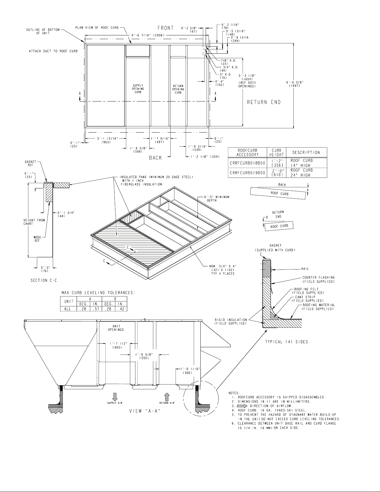
Fig. 1 — Roof Curb Details
2
Page 3
Step 2 — Remove Shipping Rails —
Remove shipping rails prior to lowering unit onto roof curb. See Fig. 2. The
rails are attached to the unit at both the return end and condenser end. Remove the screws from both ends of each rail. Be
careful not to drop the rails onto any surface that could be damaged. Discard the rails. It is important to replace the screws into
the unit to avoid any air or water leakage.
Do not allow the shipping rail to drop on the roof surface.
Damage to the roof surface may result.
Step 3 — Rig and Place Unit —
Inspect unit for transportation damage. See Table 1 for physical data. File any claim
with transportation agency.
All panels must be in place when rigging. Unit is not
designed for handling by fork truck. Damage to unit can
result.
Do not drop unit; keep upright. Use spreader bars over unit
to prevent sling or cable damage. Rollers may be used to move
unit across a roof. Level by using unit frame as a refere nce;
leveling tolerance is ±
1
/16 in. per linear ft in any direction. See
Fig. 3 for additional information. Unit rigging weight is shown
in Fig. 3.
Four lifting holes are provided in the unit base rails as
shown in Fig. 3. Refer to rigging instructions on unit.
POSITIONING — Maintain clearance, per Fig. 4, around and
above unit to provide minimum distance from combustible
materials, proper airflow, and service access.
Do not install unit in an indoor location. Do not locate air
inlets near exhaust vents or other sources of contaminated air.
Although unit is weatherproof, guard against water from
higher level runoff and overhangs.
ROOF MOUNT — Check building codes for weight distribu-
tion requirements. Unit operating weight is shown in Table 1.
INSTALLATION ONTO CURB — The 50HG units are
designed to fit on either the accessory full perimeter curb or
onto existing 48/50TJ,HJ or 48/50DP,DR curbs. In either case,
correct placement of the unit onto th e curb is critical to operating performance. To aid in correct positioning,
3
/8-in. diameter
locating holes have been added to the unit base rails. When
placing the unit, these holes should line up with the roof curb
edge as shown in Fig. 5 and 6, to assure proper duct opening
alignment. Select the alignment holes suited for the curb being
used. For installation on the HJ/TJ/DP/DR curb use the alignment holes located approximately 20 in. from the end of t he
base rail on the return end of the unit. For placement on the HG
curb, use the alignment holes located approximately 2-in. from
the end of the base rail on the return end of the unit. See labels
on the side of the unit for more details.
SHIPPING RAILS
Fig. 2 — Shipping Rail Removal
3
Page 4
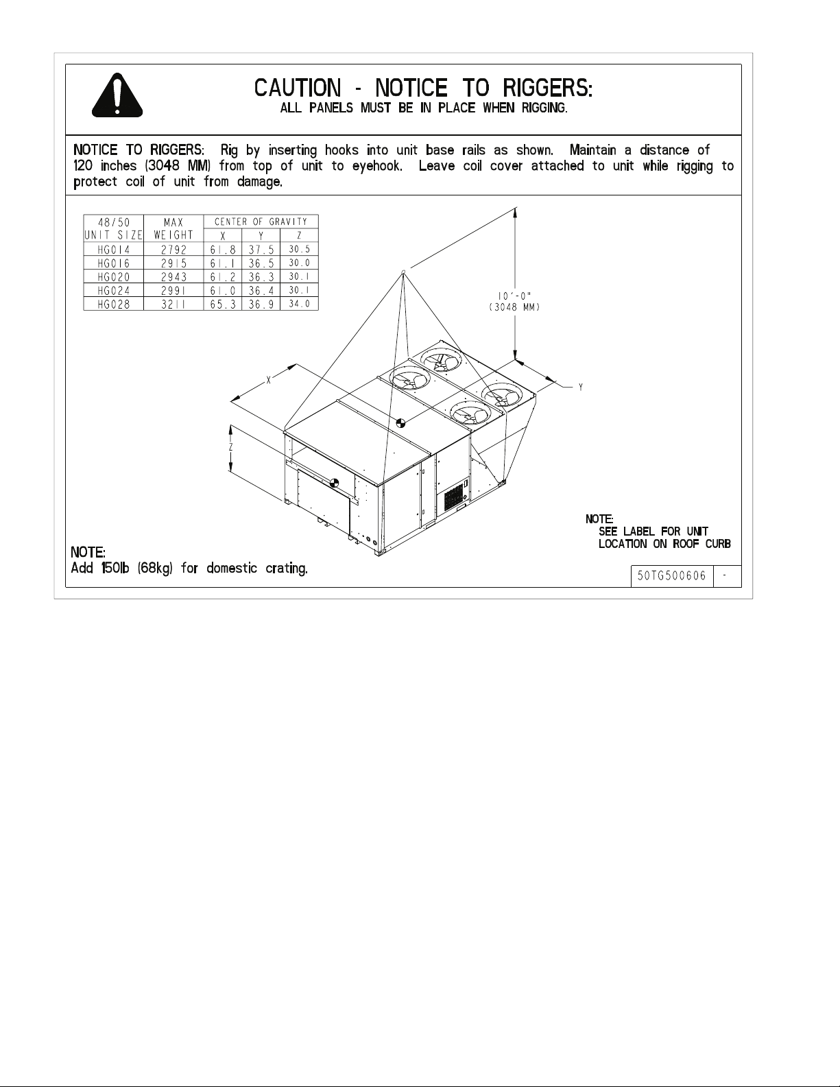
Fig. 3 — Rigging Details
4
Page 5
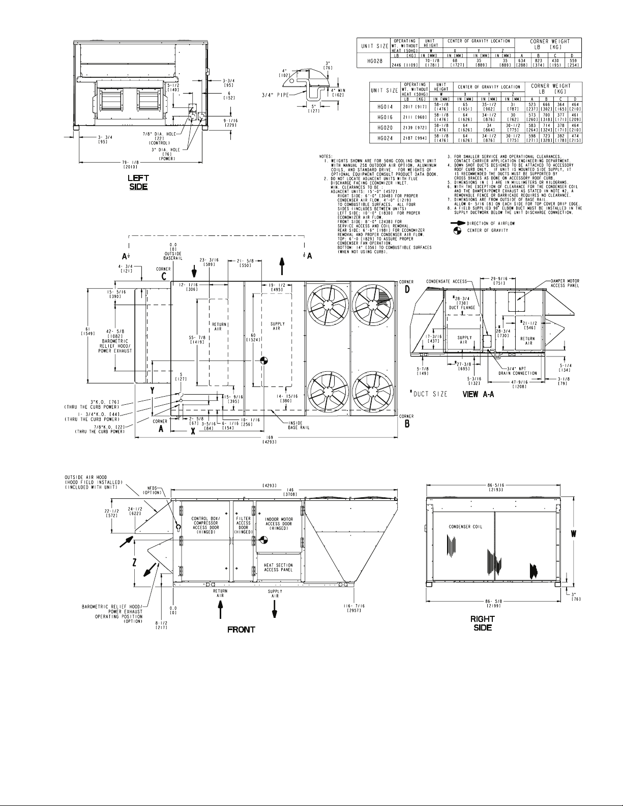
Fig. 4 — Base Unit Dimensions
5
Page 6
Table 1 — Physical Data
UNIT 50HG 014 016 020
VOLTAGE
NOMINAL CAPACITY (Tons)
OPERATING WEIGHT (lb)
50 SERIES (Cooling Only)
COMPRESSOR
Quantity
Number of Refrigerant Circuits
Oil (ounces) Ckt A...Ckt B...Ckt C
REFRIGERANT TYPE
Expansion Device
Operating Charge (lb)
Circuit A
Circuit B
Circuit C
CONDENSER COIL
Rows...Fins/inch
TotalFacearea(sq.ft)
CONDENSER FAN
Nominal Cfm (Total, all fans)
Quantity...Diameter (in.)
Motor Hp...Rpm
Watts input (Total)
EVAPORATOR COIL
Rows...Fins/inch
TotalFacearea(sq.ft)
EVAPORATOR FAN
Quantity...Size
Typ e Drive
Nominal Cfm
Std Motor Hp
Alt Motor Hp
Motor Nominal Rpm
Std Maximum Continuous Bhp
Std Maximum Continuous Watts
Alt Maximum Continuous Bhp
Alt Maximum Continuous Watts
Motor Frame Size Standard
Motor Frame Size Alternate
Fan Drive Rpm Range Std motor/Std drive
Motor Bearing Type
Maximum Allowable Rpm
Motor Pulley Pitch Diameter Std motor/Std drive
Motor Shaft Diameter (in.) Standard
Motor Shaft Diameter (in.) Alternate
Belt, Quantity...Type...Length (in.) Std motor/Std drive
Pulley center line distance (in.)
Speed change per full turn of moveable
pulley flange (rpm) Std motor/Std drive
Moveable pulley maximum (full turns
from closed position)
Factory Pulley Setting
(turns from closed position)
Fan Shaft Diameter (in.)
Factory Speed Setting (rpm)
HIGH PRESSURE SWITCHES (psig)
Cutout
Reset (Auto)
OUTDOOR AIR INLET SCREENS
Quantity...Size (in.)
RETURN AIR FILTERS
Quantity...Size (in.)
Std motor/Alt drive
Alt motor/Std drive
Alt motor/Alt drive
Std motor/Alt drive
Alt motor/Std drive
Alt motor/Alt drive
Std motor/Alt drive
Alt motor/Std drive
Alt motor/Alt drive
Std motor/Alt drive
Alt motor/Std drive
Alt motor/Alt drive
LEGEND
Brake Horsepower
Bhp —
Thermostatic Expansion Valve
TXV —
208/230
and 460
575
208/230
and 460
575
208/230
and 460
12.5 12.5 15 15 17.5 17.5
2017 2017 2111 2111 2139 2139
2 2 3333
2 2 3333
72...72...NA 72...72...NA 68...68...68 68...68...68 68...68...72 68...68...72
TXV TXV TXV TXV TXV TXV
19.6 19.6 13.2 13.2 13.1 13.1
18.3 18.3 12.2 12.2 12.7 12.7
NA NA 15.4 15.4 15.2 15.2
2...17 2...17 2...17 2...17 2...17 2...17
57.78 57.78 57.78 57.78 57.78 57.78
14,000 14,000 14,000 14,000 14,000 14,000
4...22 4...22 4...22 4...22 4...22 4...22
1
/4...1100
1400 1400 1400 1400 1400 1400
3...15 3...15 3...15 3...15 3...15 3...15
23.33 23.33 23.33 23.33 23.33 23.33
2...15x11 2...15x11 2...15x11 2...15x11 2...15x11 2...15x11
Belt Belt Belt Belt Belt Belt
5000 5000 6000 6000 7000 7000
3.7 3 3.7 3 5 5
55557
1725 1725 1725 1725 1725 1725
4.25 3.45 4.25 3.45 5.75 5.75
3171 2574 3171 2574 4290 4290
5.75 5.75 5.75 5.75 8.63 8.63
4290 4290 4290 4290 6438 6438
56HZ 56H 56HZ 56H S184T 184T
S184T 184T S184T 184T S213T S213T
485-613 472-619 618-789 609-778 658-808 658-808
618-789 609-778 485-613 472-619 794-974 794-974
778-1021 778-1021 778-1021 778-1021 949-1145 949-1145
1000-1227 1000-1227 1000-1227 1000-1227 1126-1328 1126-1328
Ball Ball Ball Ball Ball Ball
1400 1400 1400 1400 1400 1400
3.7-4.7 3.1-4.1 3.4-4.4 3.4-4.4 4.3-5.3 4.3-5.3
3.4-4.4 3.4-4.4 3.7-4.7 3.1-4.1 4.3-5.3 4.3-5.3
3.1-4.1 3.1-4.1 3.1-4.1 3.1-4.1 5.4-6.6 5.4-6.6
4.3-5.3 4.3-5.3 4.3-5.3 4.3-5.3 5.5-6.5 5.5-6.5
7
/
8
1
/
1
8
1...BX...51 1...BX...48 1...A...45 1...A...45 1...BX...46 1...BX...46
1...A...45 1...A...45 1...BX...51 1...BX...48 1...BX...42 1...BX...42
1...BX...38 1...BX...38 1...BX...38 1...BX...38 1...BX...46 1...BX...46
1...B...38 1...B...38 1...B...38 1...B...38 1...BX...42 1...BX...42
11.3-12.3 11.3-12.3 11.3-12.3 11.3-12.3 10.0-12.2 10.0-12.2
21 25 29 28 25 25
29 28 21 25 30 30
41 41 41 41 33 33
38 38 38 38 34 34
6 6 6666
3 3 3333
3
/
1
16
549 546 704 694 733 733
426 426 426 426 426 426
320 320 320 320 320 320
1
/4...1100
7
/
8
11/
13/
16
8
R-22
1
/4...11001/4...11001/4...11001/4...1100
Face Split
1
/
2
7
/
8
11/
8
13/
16
7
/
8
11/
8
13/
16
13/
11/
13/
8
8
16
3...20x25 3...20x25 3...20x25 3...20x25 3...20x25 3...20x25
9...16x25 9...16x25 9...16x25 9...16x25 9...16x25 9...16x25
575
71/
11/
13/
13/
2
8
8
16
6
Page 7
Table 1 — Physical Data (cont)
UNIT 50HG 024 028
VOLTAGE
NOMINAL CAPACITY (Tons)
OPERATING WEIGHT (lb)
50 SERIES (Cooling Only)
COMPRESSOR
Quantity
Number of Refrigerant Circuits
Oil (ounces) Ckt A...Ckt B...Ckt C
REFRIGERANT TYPE
Expansion Device
Operating Charge (lb)
Circuit A
Circuit B
Circuit C
CONDENSER COIL
Rows...Fins/inch
TotalFaceArea(sq.ft)
CONDENSER FAN
Nominal Cfm (Total, all fans)
Quantity...Diameter (in.)
Motor Hp...Rpm
Watts input (Total)
EVAPORATOR COIL
Rows...Fins/inch
TotalFaceArea(sq.ft)
EVAPORATOR FAN
Quantity...Size
Typ e Dri ve
Nominal Cfm
Std Motor Hp
Alt Motor Hp
Motor Nominal Rpm
Std Maximum Continuous Bhp
Std Maximum Continuous Watts
Alt Maximum Continuous Bhp
Alt Maximum Continuous Watts
Motor Frame Size Standard
Motor Frame Size Alternate
Fan Drive Rpm Range Std motor/Std drive
Motor Bearing Type
Maximum Allowable Rpm
Motor Pulley Pitch Diameter Std motor/Std drive
Motor Shaft Diameter (in.) Standard
Motor Shaft Diameter (in.) Alternate
Belt, Quantity...Type...Length (in.) Std motor/Std drive
Pulley center line distance (in.)
Speed change per full turn of moveable
pulley flange (rpm) Std motor/Std drive
Moveable pulley maximum (full turns
from closed position)
Factory Pulley Setting
(turns from closed position)
Fan Shaft Diameter (in.)
Factory Speed Setting (rpm)
HIGH PRESSURE SWITCHES (psig)
Cutout
Reset (Auto)
OUTDOOR AIR INLET SCREENS
Quantity...Size (in.)
RETURN AIR FILTERS
Quantity...Size (in.)
Std motor/Alt drive
Alt motor/Std drive
Alt motor/Alt drive
Std motor/Alt drive
Alt motor/Std drive
Alt motor/Alt drive
Std motor/Alt drive
Alt motor/Std drive
Alt motor/Alt drive
Std motor/Alt drive
Alt motor/Std drive
Alt motor/Alt drive
LEGEND
Bhp —
TXV —
Brake Horsepower
Thermostatic Expansion Valve
208/230
and 460
575 ALL
20 20 25
2187 2187 2446
33 2
33 2
72...72...72 72...72...72 110...110...NA
TXV TXV TXV
13.8 13.8 23.9
13.9 13.9 21.5
15.5 15.5 NA
2...17 2...17 2...17
57.78 57.78 66.67
14,000 14,000 21,000
4...22 4...22 6...22
1
/4...1100
1400 1400 2100
4...15 4...15 4...15
23.33 23.33 27.22
2...15x11 2...15x11 2...15x11
Belt Belt Belt
8000 8000 10,000
557
1
/
7
2
1725 1725 1725
5.75 5.75 8.63
4290 4290 6438
8.63 8.63 11.50
6438 6438 8579
S184T 184T S213T
S213T S213T S215T
658-808 658-808 799-965
794-974 794-974 939-1152
949-1145 949-1145 945-1187
1126-1328 1126-1328 1152-1366
Ball Ball Ball
1400 1400 1400
4.3-5.3 4.3-5.3 5.4-6.6
4.3-5.3 4.3-5.3 4.2-5.2
5.4-6.6 5.4-6.6 4.2-5.2
5.5-6.5 5.5-6.5 5.2-6.2
1
/
1
8
3
/
1
8
1...BX...46 1...BX...46 1...BX...50
1...BX...42 1...BX...42 2...AX...38
1...BX...46 1...BX...46 2...BX...38
1...BX...42 1...BX...42 2...BX...38
10.0-12.2 10.0-12.2 9.6-12.0
25 25 28
30 30 36
33 33 40
34 34 36
66 6
33 3
3
/
1
16
733 733 882
426 426 426
320 320 320
R-22
1
/4...1100
Face Split
71/
2
11/
8
13/
8
13/
16
1
/4...1100
13/
3...20x25 3...20x25 3...20x25
9...16x25 9...16x25 9...20x25
13/
13/
1
/
2
10
8
8
16
7
Page 8
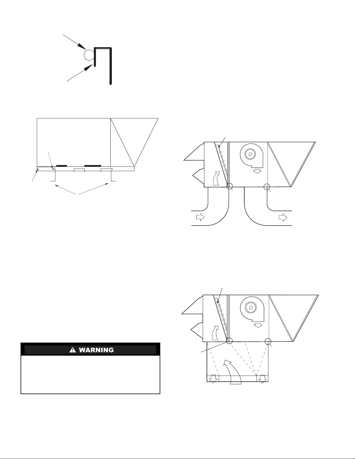
ALIGNMENT
HOLE
(IN BASE RAIL)
EDGE FLANGE
Fig. 5 — Alignment Hole Details
ALIGNMENT
HOLE SHOULD
LINE UP WITH
ROOF CURB
EDGE FLANGE
HORIZONTAL APPLICATIONS — Horizontal units are
shipped with outer panels that allow for side by side horizontal
duct connections. If specified during ordering, the unit will be
shipped with the vertical duct openings blocked off from the
factory, ready for side supply installation. If the horizontal
option was not specified at time of ordering the unit, a fieldinstalled accessory kit is required to convert the vertical unit
into a horizontal supply configuration.
Installation of the duct block-off covers should be completed prior to placing the unit unless sufficient side clearance is
available. A minimum of 66-in. is required between the unit
and any obstruction to install the duct block-off covers. Side
supply duct dimensions and locations are shown on Fig. 4.
Connect ductwork to horizontal duct flange connections on
side of unit.
ALIGNMENT
HOLES FOR
HJ, TJ, DP, DR
CURB-BOTH
SIDES
SUPPLY
OPENING
CURB
SUPPLY
OPENING
ALIGNMENT
HOLES FOR HG
CURB-BOTH
SIDES
RETURN
OPENING
CURB
RETURN
OPENING
ROOF CURB
Fig. 6 — Alignment Hole Location
Step 4 — Field Fabricate Ductwork —
Secure all
ducts to building structure. Use flexible duct connectors between unit and ducts as required. Insulate and weatherproof all
external ductwork, joints, and roof openings with counter
flashing and mastic in accordance with applicable codes.
Ducts passing through an unconditioned space must be in-
sulated and covered with a vapor barrier.
Step 5 — Make Unit Duct Connections
VERTICAL CONFIGURATION — Unit is shipped for thruthe-bottom duct connections. Ductwork openings are shown in
Fig. 1 and 4. Duct connections for vertical supply and return
configuration are shown in Fig. 7. Field fabricat ed concentric
ductwork may be connected as shown in Fig. 8 and 9. The unit
is designed to attach the ductwork to the roof curb. Do not
attach duct directly to the unit basepans.
Unit basepans must be supported under the unit and around
duct openings in order to prevent air leakage.
ECONOMIZER
SEE
NOTE
AIR
IN
NOTE: Do not drill in this area; damage to basepan may result in
water leak.
SEE
NOTE
AIR
OUT
Fig. 7 — Air Distribution —
Vertical Supply and Return
ECONOMIZER
For vertical supply and return units, tools or parts could
drop into ductwork and cause an injury. Install a 90-degree
turn in the return ductwork between the unit and the conditioned space. If a 90-degree elbow cannot be installed, then
a grille of sufficient strength a nd density should be in stalled
to prevent objects from falling into the conditioned space.
Units with electric heat require a 1-in. clearance for the first
24 in. of ductwork. Outlet grilles must not lie directly below
unit discharge.
NOTE: A 90-degree elbow must be provided in the supply
ductwork to comply with UL (Underwriters’ Laboratories)
codes for use with electric heat.
AIR OUT
SEE
NOTE
SEE
NOTE
AIR OUT
NOTE: Do not drill in this area; damage to basepan may result in
water leak.
AIR IN
Fig. 8 — Air Distribution — Concentric Duct
8
Page 9

NOTE: Dimensions A, A′,B,andB′
c
eiling diffuser.
Shaded areas indicate block-off pans.
are obtained from field-supplied
Fig. 9 — Concentric Duct Details
Step 6 — Trap Condensate Drain —
for drain location. One
3
/4-in. half coupling is provided outside
See Fig. 10
unit evaporator section for condensate drain connection. A trap
at least 4-in. deep must be used. See Fig. 11.
Step 7 — Make Electrical Connections
FIELD POWER SUPPLY — Unit is factory wired for voltage shown on unit nameplate.
When installing units, provide disconnect per NEC (National Electrical Code) of adequate size (MOCP [Maximum
Overcurrent protection] of unit is on the informative plate). See
T ables 2A and 2B. All field wiring must comply with NEC and
local codes. Size wire based on MCA (Minimum Circuit
Amps) on the unit informative plate. See Fig. 12 for power
wiring connections to the unit power terminal block and
equipment grounds.
Route power and ground lines through control box end panel or unit basepan (see Fig. 4) to connections as shown on unit
wiring diagram and Fig. 12.
Operating voltage to compressor must be within voltage
range indicated on unit nameplate. On 3-phase units, voltages
between phases must be balanced within 2%.
Unit failure as a result of operation on improper line voltage
or excessive phase imbalance constitutes abuse and may cause
damage to electrical components.
FIELD CONTROL WIRING — Unit can be controlled with
either a Carrier-approved accessory thermostat or a Carrierapproved space temperature sensor. Install thermostat according to the installation instructions included with accessory.
Locate thermostat assembly or space temperature sensor on a
solid interior wall in the conditioned space to sense average
temperature.
Route thermostat or space temperature sensor cable or
equivalent single leads of colored wire from subbase terminals
through conduit into unit to low-voltage connections as shown
on unit label wiring diagram and in Fig. 13 or 14.
NOTE: For wire runs up to 50 ft, use no. 18 AWG (American
Wire Gage) insulated wire (35 C minimum). For 50 to 75 ft,
use no. 16 AWG insulated wire (35 C minimum). For over
75 ft, use no. 14 AWG insulated wire (35 C Minimum). All
wire larger than no. 18 AWG cannot be directly connected at
the thermostat and will require a junction box and splice at the
thermostat.
Fig. 10 — Condensate Drain Details
The correct power phasing is critical to the operation of the
scroll compressors. An incorrect phasing will result in an
alarm being generated and compressor operation l ockout.
Should this occur, power phase correction must be made to
the incoming p ow er.
The unit must be electrically grounded in accordance with
local codes and NEC ANSI/NFPA 70 (American National
Standards Institute/National Fire Protection Association).
Field wiring must conform to temperature limitations for
type ‘‘T’’ wire. All field wiring mu st comply with NEC and
local requirements.
NOTE: Dimensions in [] are in millimeters.
Fig. 11 — Condensate Drain Piping Details
9
Page 10
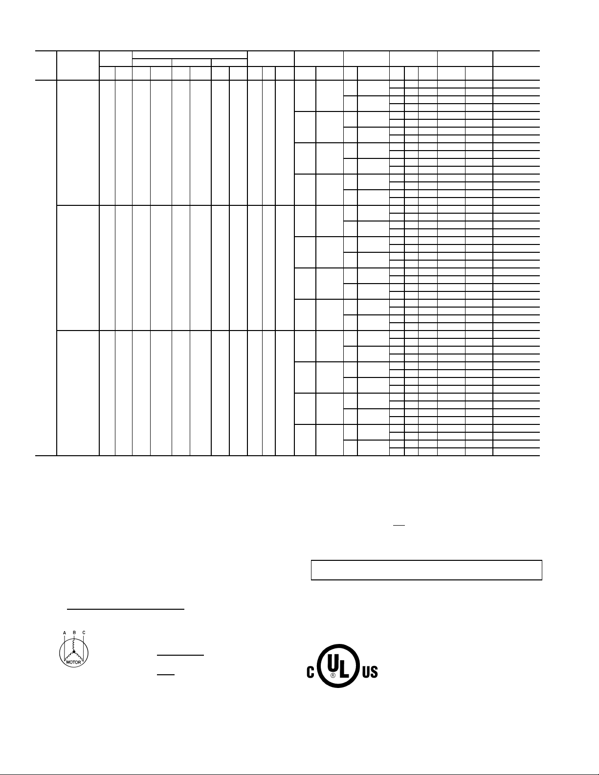
Table 2A — Electrical Data (Units Without Optional Convenience Outlet)
UNIT
NOMINAL
SIZE
VO LTAGE
50HG
(3 Ph, 60 Hz)
208/230 187 253 19.2 146.0 19.2 146.0 — — 4.01/41.5
014
FLA — Full Load Amps MCA — Minimum Circuit Amps
HACR — Heating, Air Conditioning and MOCP — Maximum Overcurrent Protection
IFM — Indoor (Evaporator) Fan Motor OFM — Outdoor (Condenser) Fan Motor
LRA — Locked Rotor Amps RLA — Rated Load Amps
*Fuse or HACR circuit breaker.
†208/230 v 75-kW Electric Heat units must use dual-point wiring. The main table lists the
branch circuit values for the refrigeration part of the system. The following two tables list
the branch circuit values for the electric heat and values for a feeder circuit for both branch
circuits.
NOTES:
1. In compliance w ith NEC requirements for multimotor and combination load equipment
(refer to NEC Articles 430 and 440), the overcurrent protective device for the unit shall
be fuse or HACR breaker. Canadian units may be fuse or circuit breaker.
2. Unbalanced 3-Phase Supply Voltage
Never operate a motor where a phase imbalance in supply voltage is greater than 2%.
Use the following formula to determine the percent of voltage imbalance.
%Voltage Imbalance
= 100 x
Example: Supply voltage is 460-3-60.
460 414 5069.5 73.0 9.5 73.0 — — 4.01/40.7
575 518 633 7.6 58.4 7.6 58.4 — — 4.01/40.7
Refrigeration NEC — National Electrical Code
max voltage deviation fr om average voltage
VO LTAGE
RANGE
Min Max RLA LRA RLA LRA RLA LRA Qty Hp
average voltage
AB=452 v
BC = 464v
AC = 455 v
Average Voltage =
COMPRESSOR
No. 1 No. 2 No. 3
LEGEND AND NOTES FOR TABLES 2A AND 2B
LEGEND
452 + 464 + 455
3
1371
=
3
=
457
OFM
ELECTRIC
FLA
(ea)
HEAT
kW FLA Hp FLA Qty Hp
——
12/16 33/ 38
19/25 52/ 60
38/50 104/120
——
15 18
25 30
50 60
——
16 15
25 24
48 46
Determine maximum deviation from average voltage.
(AB) 457 – 452 = 5v
(BC) 464 – 457 = 7v
(AC) 457 – 455 = 2v
Maximum deviation is 7 v.
Determine percent of voltage imbalance.
%Voltage Imbalance = 100 x
This amount of phase imbalance is satisfactory as it is below the maximum allowable
2%.
IMPORTANT: If the supply voltage phase imbalance is more than 2%, contact your
local electric utility company immediately.
3. The 75-kW 208/240-v electric heat can be factory installed but it must be wired separately in the field.
4. The convenience outlet full load amps (FLA) are 5, 3 and 3 for 208/230, 460, 575-v
units, respectively.
5. The FLA load amps provided in the table for electric heaters are based on 208/240, 480
and 600v.
6. MCA calculation for 50HG014-028 units with electric heaters over 50 kW is = 1.25 x
(IFM+Power Exhaust + Convenience Outlet FLA amps) + 1.00 x (Electric Heater FLA).
IFM
3.7 10.6/ 9.6
5.0 16.7/15.2
3.7 10.6/ 9.6
5.0 16.7/15.2
3.7 10.6 /9.6
5.0 16.7/15.2
3.7 10.6/ 9.6
5.0 16.7/15.2
3.7 4.8
5.0 7.6
3.7 4.8
5.0 7.6
3.7 4.8
5.0 7.6
3.7 4.8
5.0 7.6
3.0 3.9
5.0 6.1
3.0 3.9
5.0 6.1
3.0 3.9
5.0 6.1
3.0 3.9
5.0 6.1
= 1.53%
POWER
EXHAUST
FLA
(ea)
—— — 60/ 59 70/ 70 70/ 70
21.05.9 72/ 71 90/ 80 80/ 80
—— — 66/ 64 80/ 80 80/ 70
21.05.9 78/ 7690/ 90 90/ 90
—— — 60/ 60 70/ 70 70/ 70
21.05.9 72/ 74 90/ 80 80/ 80
—— — 66/ 67 80/ 80 80/ 70
21.05.9 78/ 81 90/ 90 90/ 90
— — — 78/ 87 80/ 90 80/ 90
21.05.993/102 100/110 90/100
—— — 86/ 94 90/100 80/ 90
21.05.9 101/109 110/110 100/110
— — — 143/132 150/150 150/150
21.05.9 158/147 175/150 150/175
— — — 151/139 175/150 150/175
21.05.9 166/154 175/175 175/175
—— — 29 35 35
21.03.1 35 40 40
—— — 32 40 35
21.03.1 38 45 45
—— — 29 35 35
21.03.1 36 40 40
—— — 32 40 35
21.03.1 40 45 45
—— — 44 45 45
21.03.1 51 6050
—— — 47 50 45
21.03.1 55 60 60
—— — 66 80 80
21.03.1 74 80 90
—— — 70 80 80
21.03.1 77 80 90
—— — 24 30 30
21.03.1 30 35 35
—— — 26 30 30
21.03.1 32 35 35
—— — 24 30 30
21.03.1 31 35 35
—— — 26 30 30
21.03.1 34 35 35
—— — 35 35 35
21.03.1 43 45 40
—— — 38 40 35
21.03.1 45 50 45
—— — 6270 60
21.03.1 70 80 70
—— — 6570 60
21.03.1 73 80 70
7
457
POWER
SUPPLY
MCA MOCP* FLA
DISCONNECT
SIZE
10
Page 11

Table 2A — Electrical Data (Units Without Optional Convenience Outlet) (cont)
UNIT
NOMINAL
SIZE
VO LTAGE
50HG
(3 Ph, 60 Hz)
208/230 187 253 16.7 130.0 16.7 130.0 16.7 130.0 4.01/41.5
016
VO LTAGE
RANGE
Min Max RLA LRA RLA LRA RLA LRA Qty Hp
460 414 506 9.0 70.0 9.0 70.0 9.0 70.0 4.01/40.7
575 518 633 7.0 55.0 7.0 55.0 7.0 55.0 4.01/40.7
COMPRESSOR
No. 1 No. 2 No. 3
OFM
ELECTRIC
FLA
(ea)
HEAT
kW FLA Hp FLA Qty Hp
——
19/25 52/ 60
38/50 104/120
56/75† 156/180
——
25 30
50 60
75 90
——
25 24
48 46
78 75
IFM
3.7 10.6/ 9.6
5.0 16.7/15.2
3.7 10.6/ 9.6
5.0 16.7/15.2
3.7 10.6/ 9.6
5.0 16.7/15.2
3.7 10.6/ 9.6
5.0 16.7/15.2
3.7 4.8
5.0 7.6
3.7 4.8
5.0 7.6
3.7 4.8
5.0 7.6
3.7 4.8
5.0 7.6
3.0 3.9
5.0 6.1
3.0 3.9
5.0 6.1
3.0 3.9
5.0 6.1
3.0 3.9
5.0 6.1
POWER
EXHAUST
FLA
(ea)
—— — 71/ 70 80/ 80 80/ 80
2 1.0 5.9 83/ 82 90/ 90 100/ 90
—— — 77/ 75 90/ 90 90/ 90
2 1.0 5.9 89/ 87 100/100 100/100
—— — 78/ 87 80/ 90 80/ 90
2 1.0 5.9 93/102 100/110 100/100
—— — 86/ 94 90/100 90/ 90
2 1.0 5.9 101/109 110/110 100/110
—— — 143/132 150/150 150/150
2 1.0 5.9 158/147 175/150 150/175
—— — 151/139 175/150 150/175
2 1.0 5.9 166/154 175/175 175/175
—— — 71/ 70† 80/ 80† 80/ 80†
2 1.0 5.9 83/ 82† 90/ 90† 100/ 90†
—— — 77/ 75† 90/ 90† 90/ 90†
2 1.0 5.9 89/ 87† 100/100† 100/100†
—— — 37 45 40
21.03.1 43 50 50
—— — 40 45 45
21.03.1 46 50 60
—— — 44 45 45
21.03.1 51 60 50
—— — 47 50 45
21.03.1 55 60 60
—— — 66 80 80
21.03.1 74 80 90
—— — 70 80 80
21.03.1 77 80 90
—— — 96 110 110
2 1.0 3.1 104 110 125
—— — 100 110 125
2 1.0 3.1 107 125 125
—— — 29 35 35
21.03.1 36 40 40
—— — 32 35 35
21.03.1 38 40 45
—— — 35 35 35
21.03.1 43 45 40
—— — 38 40 35
21.03.1 45 50 45
—— — 62 70 60
21.03.1 70 80 70
—— — 65 70 60
21.03.1 73 80 70
—— — 80 90 100
2 1.0 3.1 88 100 100
—— — 83 90 100
2 1.0 3.1 90 100 110
POWER
SUPPLY
MCA MOCP* FLA
DISCONNECT
SIZE
ELECTRIC HEAT BRANCH CIRCUIT FOR 208/240-V 75-kW ELECTRIC HEAT
UNIT
NOMINAL
SIZE
VO LTAGE
50HG
(3 Ph, 60 Hz)
016 208/240 187 253 NA NA NA NA NA NA NA NA NA 56/75 156/180 NA NA NA NA NA 156/180 175/200 200/225
VO LTAGE
RANGE
Min Max RLA LRA RL A LRA RLA LRA Qty Hp
COMPRESSOR
No. 1 No. 2 No. 3
OFM
ELECTRIC
FLA
(ea)
HEAT
kW FLA Hp FLA Qty Hp
IFM
POWER
EXHAUST
POWER
FLA
(ea)
SUPPLY
MCA MOCP* FLA
DISCONNECT
FEEDER CIRCUIT FOR 208/230-V UNIT WITH 75-kW ELECTRIC HEAT
UNIT
NOMINAL
SIZE
VO LTAGE
50HG
(3 Ph, 60 Hz)
016 208/230 187 253 16.7 130.0 16.7 130.0 16.7 130.0 4.01/41.5 56/75 156/180
See Legend and Notes on page 10.
VO LTAGE
RANGE
Min Max RLA LRA RLA LRA RLA LRA Qty Hp
COMPRESSOR
No. 1 No. 2 No. 3
OFM
ELECTRIC
FLA
(ea)
HEAT
kW FLA Hp FLA Qty Hp
IFM
3.7 10.6/ 9.6
5.0 16.7/15.2
POWER
EXHAUST
FLA
(ea)
—— — 169/192 200/225 200/225
2 1.0 5.9 184/207 200/225 225/250
—— — 177/199 200/225 200/225
2 1.0 5.9 192/214 200/225 225/250
POWER
SUPPLY
MCA MOCP* FLA
DISCONNECT
11
SIZE
SIZE
Page 12
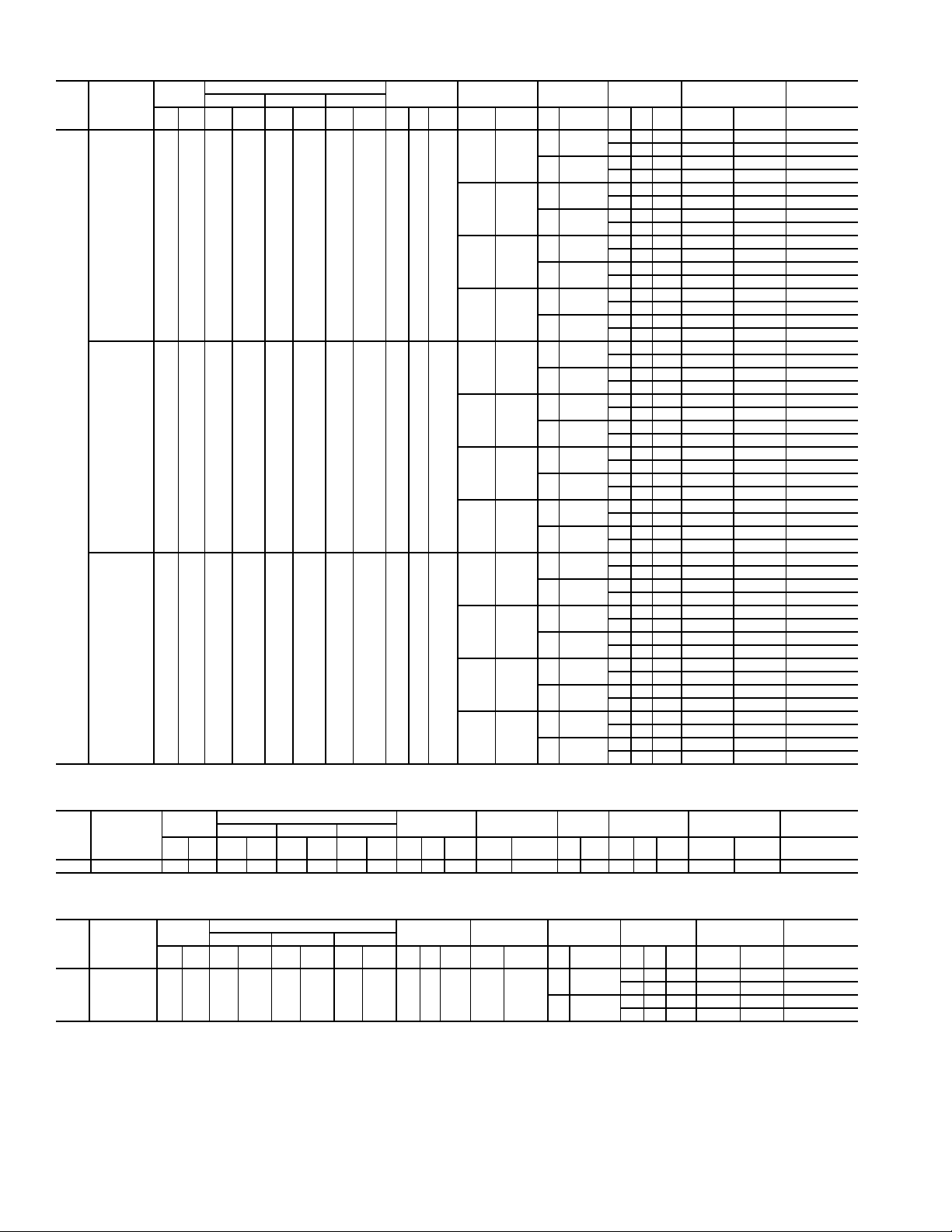
Table 2A — Electrical Data (Units Without Optional Convenience Outlet) (cont)
UNIT
NOMINAL
SIZE
VO LTAGE
50HG
(3 Ph, 60 Hz)
208/230 187 253 16.7 130.0 16.7 130.0 22.4 184.0 4.01/41.5
020
VO LTAGE
RANGE
Min Max RLA LRA RLA LRA RL A LRA Qty Hp
460 414 506 9.0 70.0 9.0 70.0 10.7 90.0 4.01/40.7
575 518 633 7.0 55.0 7.0 55.0 9.3 73.0 4.01/40.7
COMPRESSOR
No. 1 No. 2 No. 3
OFM
ELECTRIC
FLA
(ea)
HEAT
kW FLA Hp FLA Qty Hp
5.0 16.7/15.2
——
7.5 24.2/22.0
5.0 16.7/15.2
19/25 52/ 60
7.5 24.2/22.0
5.0 16.7/15.2
38/50 104/120
7.5 24.2/22.0
5.0 16.7/15.2
56/75† 156/180
7.5 24.2/22.0
5.0 7.6
——
7.5 11.0
5.0 7.6
25 30
7.5 11.0
5.0 7.6
50 60
7.5 11.0
5.0 7.6
75 90
7.5 11.0
5.0 6.1
——
7.5 9.0
5.0 6.1
25 24
7.5 9.0
5.0 6.1
48 46
7.5 9.0
5.0 6.1
78 75
7.5 9.0
IFM
POWER
EXHAUST
FLA
(ea)
—— — 84/ 83 100/100 100/ 90
2 1.0 5.9 96/ 94 110/110 110/110
—— — 92/ 89 110/110 100/100
2 1.0 5.9 104/101 125/110 125/110
—— — 86/ 94 100/100 100/ 90
2 1.0 5.9 101/109 110/110 110/110
—— — 95/103 110/110 100/100
2 1.0 5.9 110/117 125/125 125/110
—— — 151/139 175/150 150/175
2 1.0 5.9 166/154 175/175 175/175
—— — 160/148 175/150 150/175
2 1.0 5.9 175/162 200/175 175/200
—— — 84/ 83† 100/100† 100/ 90†
2 1.0 5.9 96/ 94† 110/110† 110/110†
—— — 92/ 89† 110/110† 100/100†
2 1.0 5.9 104/101† 125/110† 125/110†
—— — 42 50 45
21.03.1 48 50 60
—— — 45 50 50
21.03.1 51 60 60
—— — 47 50 45
21.03.1 55 60 60
—— — 51 60 50
21.03.1 59 60 60
—— — 70 80 80
21.03.1 77 80 90
—— — 74 80 90
21.03.1 82 90 90
—— — 100 110 125
2 1.0 3.1 107 125 125
—— — 104 125 125
2 1.0 3.1 112 125 125
—— — 35 40 40
21.03.1 41 50 45
—— — 37 45 45
21.03.1 44 50 50
—— — 38 40 40
21.03.1 45 50 45
—— — 41 45 45
21.03.1 49 50 50
—— — 65 70 60
21.03.1 73 80 70
—— — 69 70 70
21.03.1 77 80 80
—— — 83 90 100
2 1.0 3.1 90 100 110
—— — 86 100 100
2 1.0 3.1 94 100 110
POWER
SUPPLY
MCA MOCP* FLA
DISCONNECT
SIZE
ELECTRIC HEAT BRANCH CIRCUIT FOR 208/240-V 75-kW ELECTRIC HEAT
UNIT
NOMINAL
SIZE
VO LTAGE
50HG
(3 Ph, 60 Hz)
020 208/240 187 253 NA NA NA NA NA NA NA NA NA 56/75 156/180 NA NA NA NA NA 156/180 175/200 200/225
VO LTAGE
RANGE
Min Max RLA LRA RL A LRA RLA LRA Qty Hp
COMPRESSOR
No.1 No.2 No.3
OFM
ELECTRIC
FLA
(ea)
HEAT
kW FLA Hp FLA Qty Hp
IFM
POWER
EXHAUST
POWER
FLA
(ea)
SUPPLY
MCA MOCP* FLA
DISCONNECT
FEEDER CIRCUIT FOR 208/230-V UNIT WITH 75-kW ELECTRIC HEAT
UNIT
NOMINAL
SIZE
VO LTAGE
50HG
(3 Ph, 60 Hz)
020 208/230 187 253 16.7 130.0 16.7 130.0 22.4 184.0 4.01/41.5 56/75 156/180
See Legend and Notes on page 10.
VO LTAGE
RANGE
Min Max RLA LRA RLA LRA RLA LRA Qty Hp
COMPRESSOR
No. 1 No. 2 No. 3
OFM
ELECTRIC
FLA
(ea)
HEAT
kW FLA Hp FLA Qty Hp
IFM
5.0 16.7/15.2
7.5 24.2/22.0
POWER
EXHAUST
FLA
(ea)
—— — 177/199 200/225 200/225
2 1.0 5.9 192/214 200/225 225/250
—— — 186/208 200/225 225/250
2 1.0 5.9 201/222 225/225 225/250
POWER
SUPPLY
MCA MOCP* FLA
DISCONNECT
12
SIZE
SIZE
Page 13
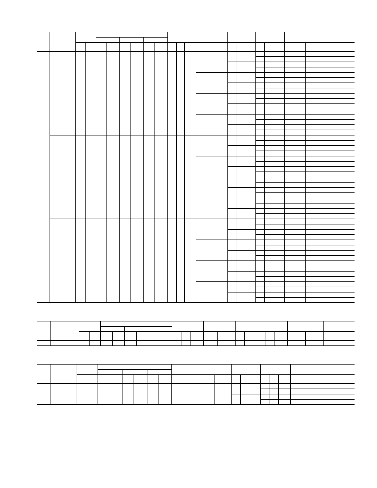
Table 2A — Electrical Data (Units Without Optional Convenience Outlet) (cont)
UNIT
NOMINAL
SIZE
VO LTAGE
50HG
(3 Ph, 60 Hz)
208/230 187 253 22.4 184.0 22.4 184.0 22.4 184.0 4.01/41.5
024
VO LTAGE
RANGE
Min Max RLA LRA RLA LRA RL A LRA Qty Hp
460 414 506 10.7 90.0 10.7 90.0 10.7 90.0 4.01/40.7
575 518 633 9.3 73.0 9.3 73.0 9.3 73.0 4.01/40.7
COMPRESSOR
No. 1 No. 2 No. 3
OFM
ELECTRIC
FLA
(ea)
HEAT
kW FLA Hp FLA Qty Hp
——
19/25 52/ 60
38/50 104/120
56/75† 156/180
——
25 30
50 60
75 90
——
25 24
48 46
78 75
IFM
5.0 16.7/15.2
7.5 24.2/22.0
5.0 16.7/15.2
7.5 24.2/22.0
5.0 16.7/15.2
7.5 24.2/22.0
5.0 16.7/15.2
7.5 24.2/22.0
5.0 7.6
7.5 11.0
5.0 7.6
7.5 11.0
5.0 7.6
7.5 11.0
5.0 7.6
7.5 11.0
5.0 6.1
7.5 9.0
5.0 6.1
7.5 9.0
5.0 6.1
7.5 9.0
5.0 6.1
7.5 9.0
POWER
EXHAUST
FLA
(ea)
—— — 96/ 94 110/110 110/110
2 1.0 5.9 107/106 125/125 125/125
—— — 104/101 125/110 125/110
2 1.0 5.9 115/113 125/125 150/125
—— — 96/ 94 110/110 110/110
2 1.0 5.9 107/109 125/125 125/125
—— — 104/103 125/110 125/110
2 1.0 5.9 115/117 125/125 150/125
—— — 151/139 175/150 150/175
2 1.0 5.9 166/154 175/175 175/175
—— — 160/148 175/150 150/175
2 1.0 5.9 175/162 200/175 175/200
—— — 96/ 94† 110/110† 110/110†
2 1.0 5.9 107/106† 125/125† 125/125†
—— — 104/101† 125/110† 125/110†
2 1.0 5.9 115/113† 125/125† 150/125†
—— — 45 50 50
21.03.1 51 60 60
—— — 49 50 60
21.03.1 55 60 60
—— — 47 50 50
21.03.1 55 60 60
—— — 51 60 60
21.03.1 59 60 60
—— — 70 80 80
21.03.1 77 80 90
—— — 74 80 90
21.03.1 82 90 90
—— — 100 110 125
2 1.0 3.1 107 125 125
—— — 104 125 125
2 1.0 3.1 112 125 125
—— — 39 45 45
21.03.1 45 50 50
—— — 42 50 50
21.03.1 48 50 60
—— — 39 45 45
21.03.1 45 50 50
—— — 42 50 50
21.03.1 49 50 60
—— — 65 70 60
21.03.1 73 80 70
—— — 69 70 70
21.03.1 77 80 80
—— — 83 90 100
2 1.0 3.1 90 100 110
—— — 86 100 100
2 1.0 3.1 94 100 110
POWER
SUPPLY
MCA MOCP* FLA
DISCONNECT
SIZE
ELECTRIC HEAT BRANCH CIRCUIT FOR 208/240-V 75-kW ELECTRIC HEAT
UNIT
NOMINAL
SIZE
VO LTAGE
50HG
(3 Ph, 60 Hz)
024 208/240 187 253 NA NA NA NA NA NA NA NA NA 56/75 156/180 NA NA NA NA NA 156/180 175/200 200/225
VO LTAGE
RANGE
Min Max RLA LRA RL A LRA RLA LRA Qty Hp
COMPRESSOR
No. 1 No. 2 No. 3
OFM
ELECTRIC
FLA
(ea)
HEAT
kW FLA Hp FLA Qty Hp
IFM
POWER
EXHAUST
POWER
FLA
(ea)
SUPPLY
MCA MOCP* FLA
DISCONNECT
FEEDER CIRCUIT FOR 208/230-V UNIT WITH 75-kW ELECTRIC HEAT
UNIT
NOMINAL
SIZE
VO LTAGE
50HG
(3 Ph, 60 Hz)
024 208/230 187 253 22.4 184.0 22.4 184.0 22.4 184.0 4.01/41.5 56/75 156/180
See Legend and Notes on page 10.
VO LTAGE
RANGE
Min Max RLA LRA RLA LRA RLA LRA Qty Hp
COMPRESSOR
No. 1 No. 2 No. 3
OFM
ELECTRIC
FLA
(ea)
HEAT
kW FLA Hp FLA Qty Hp
IFM
5.0 16.7/15.2
7.5 24.2/22
POWER
EXHAUST
FLA
(ea)
—— — 177/199 200/225 200/225
2 1.0 5.9 192/214 200/225 225/250
—— — 186/208 200/225 225/250
2 1.0 5.9 201/222 225/225 225/250
POWER
SUPPLY
MCA MOCP* FLA
DISCONNECT
13
SIZE
SIZE
Page 14

Table 2A — Electrical Data (Units Without Optional Convenience Outlet) (cont)
UNIT
NOMINAL
SIZE
VO LTAGE
50HG
(3 Ph, 60 Hz)
208/230 187 253 47.1 245.0 47.1 245.0 ——6.01/41.5
028
VO LTAGE
RANGE
Min Max RLA LRA RLA LRA RLA LRA Qty Hp
460 414 506 19.6 125.0 19.6 125.0 ——6.01/40.7
575 518 633 15.8 100.0 15.8 100.0 ——6.01/40.7
COMPRESSOR
No. 1 No. 2 No. 3
OFM
ELECTRIC
FLA
(ea)
HEAT
kW FLA Hp FLA Qty Hp
——
19/25 52/ 60
38/50 104/120
56/75† 156/180
——
25 30
50 60
75 90
——
25 24
48 46
78 75
IFM
7.5 24.2/22.0
10.0 30.8/28.0
7.5 24.2/22.0
10.0 30.8/28.0
7.5 24.2/22.0
10.0 30.8/28.0
7.5 24.2/22.0
10.0 30.8/28.0
7.5 11.0
10.0 14.0
7.5 11.0
10.0 14.0
7.5 11.0
10.0 14.0
7.5 11.0
10.0 14.0
7.5 9.0
10.0 11.0
7.5 9.0
10.0 11.0
7.5 9.0
10.0 11.0
7.5 9.0
10.0 11.0
POWER
EXHAUST
FLA
(ea)
—— — 139/137 175/175 150/150
2 1.0 5.9 151/149 175/175 175/175
—— — 146/143 175/175 175/175
2 1.0 5.9 158/155 200/200 175/175
—— — 139/137 175/175 150/150
2 1.0 5.9 151/149 175/175 175/175
—— — 146/143 175/175 175/175
2 1.0 5.9 158/155 200/200 175/175
—— — 160/148 175/175 150/175
2 1.0 5.9 175/162 200/175 175/200
—— — 169/155 175/175 175/175
2 1.0 5.9 183/170 200/200 175/200
—— — 139/137† 175/175† 150/150†
2 1.0 5.9 151/149† 175/175† 175/175†
—— — 146/143† 175/175† 175/175†
2 1.0 5.9 158/155† 200/200† 175/175†
—— — 59 70 70
21.03.1 66 80 70
—— — 62 80 70
21.03.1 69 80 80
—— — 59 70 70
21.03.1 66 80 70
—— — 62 80 70
21.03.1 69 80 80
—— — 74 80 90
21.03.1 82 90 90
—— — 78 90 90
21.03.1 85 90 100
—— — 104 125 125
2 1.0 3.1 112 125 125
—— — 108 125 125
2 1.0 3.1 115 125 150
—— — 49 60 60
21.03.1 55 70 60
—— — 51 60 60
21.03.1 57 70 70
—— — 49 60 60
21.03.1 55 70 60
—— — 51 60 60
21.03.1 57 70 70
—— — 69 70 70
21.03.1 77 80 80
—— — 71 80 70
21.03.1 79 80 80
—— — 86 100 100
2 1.0 3.1 94 100 110
—— — 89 100 100
2 1.0 3.1 97 100 110
POWER
SUPPLY
MCA MOCP* FLA
DISCONNECT
SIZE
ELECTRIC HEAT BRANCH CIRCUIT FOR 208/240-V 75-kW ELECTRIC HEAT
UNIT
NOMINAL
SIZE
VO LTAGE
50HG
(3 Ph, 60 Hz)
028 208/240 187 253 NA NA NA NA NA NA NA NA NA 56/75 156/180 NA NA NA NA NA 156/180 175/200 200/225
VO LTAGE
RANGE
Min Max RLA LRA RL A LRA RLA LRA Qty Hp
COMPRESSOR
No.1 No.2 No.3
OFM
ELECTRIC
FLA
(ea)
HEAT
kW FLA Hp FLA Qty Hp
IFM
POWER
EXHAUST
POWER
FLA
(ea)
SUPPLY
MCA MOCP* FLA
DISCONNECT
FEEDER CIRCUIT FOR 208/230-V UNIT WITH 75-kW ELECTRIC HEAT
UNIT
NOMINAL
SIZE
VO LTAGE
50HG
(3 Ph, 60 Hz)
028 208/230 187 253 47.1 245.0 47.1 245.0 ——6.01/41.5 56/75 156/180
See Legend and Notes on page 10.
VO LTAGE
RANGE
Min Max RLA LRA RLA LRA RLA LRA Qty Hp
COMPRESSOR
No. 1 No. 2 No. 3
OFM
ELECTRIC
FLA
(ea)
HEAT
kW FLA Hp FLA Qty Hp
IFM
7.5 24.2/22.0
10.0 30.8/28.0
POWER
EXHAUST
FLA
(ea)
—— — 186/208 200/225 225/250
2 1.0 5.9 201/222 225/225 225/250
—— — 195/215 225/225 225/250
2 1.0 5.9 209/230 225/250 250/300
POWER
SUPPLY
MCA MOCP* FLA
DISCONNECT
14
SIZE
SIZE
Page 15

UNIT
NOMINAL
SIZE
VO LTAGE
50HG
(3 Ph, 60 Hz)
208/230 187 253 19.2 146.0 19.2 146.0 ——4.01/41.5
014
See Legend and Notes on page 10.
460 414 506 9.5 73.0 9.5 73.0 ——4.01/40.7
575 518 633 7.6 58.4 7.6 58.4 ——4.01/40.7
VO LTAGE
RANGE
Min Max RLA LRA RLA LRA RLA LRA Qty Hp
Table 2B — Electrical Data (Units With Optional Convenience Outlet)
COMPRESSOR
No. 1 No. 2 No. 3
OFM
ELECTRIC
FLA
(ea)
HEAT
kW FLA Hp FLA Qty Hp
——
12/16 33/ 38
19/25 52/ 60
38/50 104/120
——
15 18
25 30
50 60
——
16 15
25 24
48 46
IFM
3.7 10.6/ 9.6
5.0 16.7/15.2
3.7 10.6/ 9.6
5.0 16.7/15.2
3.7 10.6/ 9.6
5.0 16.7/15.2
3.7 10.6/ 9.6
5.0 16.7/15.2
3.7 4.8
5.0 7.6
3.7 4.8
5.0 7.6
3.7 4.8
5.0 7.6
3.7 4.8
5.0 7.6
3.0 3.9
5.0 6.1
3.0 3.9
5.0 6.1
3.0 3.9
5.0 6.1
3.0 3.9
5.0 6.1
POWER
EXHAUST
FLA
(ea)
—— — 65/ 64 80/ 80 70/ 70
2 1.0 5.9 77/ 76 90/ 90 80/ 80
—— — 71/ 69 90/ 80 80/ 70
2 1.0 5.9 83/ 81 100/100 90/ 90
—— — 65/ 66 80/ 80 70/ 70
2 1.0 5.9 77/ 81 90/ 90 80/ 80
—— — 71/ 73 90/ 80 80/ 70
2 1.0 5.9 83/ 88 100/100 90/ 90
—— — 85/ 93 90/100 80/ 90
2 1.0 5.9 99/108 100/110 90/100
—— — 92/100 100/110 80/ 90
2 1.0 5.9 107/115 110/125 100/110
—— — 150/138 150/150 150/150
2 1.0 5.9 164/153 175/175 150/175
—— — 157/145 175/150 150/175
2 1.0 5.9 172/160 175/175 175/175
—— — 32 40 35
21.03.1 38 45 40
—— — 35 40 35
21.03.1 41 50 45
—— — 32 40 35
21.03.1 40 45 40
—— — 36 40 35
21.03.1 44 50 45
—— — 47 50 45
21.03.1 55 60 50
—— — 51 60 45
21.03.1 59 60 60
—— — 70 80 80
21.03.1 78 80 90
—— — 73 80 80
21.03.1 81 90 90
—— — 27 30 30
21.03.1 33 40 35
—— — 29 35 30
21.03.1 36 40 35
—— — 27 30 30
21.03.1 35 40 35
—— — 30 35 30
21.03.1 38 40 35
—— — 39 40 35
21.03.1 46 50 40
—— — 41 45 35
21.03.1 49 50 45
—— — 66 70 60
21.03.1 74 80 70
—— — 69 70 60
21.03.1 77 80 70
POWER
SUPPLY
MCA MOCP* FLA
DISCONNECT
SIZE
15
Page 16
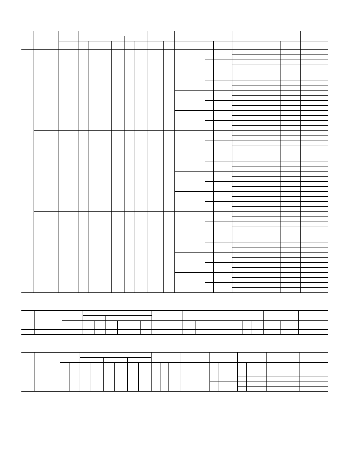
Table 2B — Electrical Data (Units With Optional Convenience Outlet) (cont)
UNIT
NOMINAL
SIZE
VO LTAGE
50HG
(3 Ph, 60 Hz)
208/230 187 253 16.7 130.0 16.7 130.0 16.7 130.0 4.01/41.5
016
VO LTAGE
RANGE
Min Max RLA LRA RLA LRA RLA LRA Qty Hp
460 414 506 9.0 70.0 9.0 70.0 9.0 70.0 4.01/40.7
575 518 633 7.0 55.0 7.0 55.0 7.0 55.0 4.01/40.7
COMPRESSOR
No.1 No.2 No.3
OFM
ELECTRIC
FLA
(ea)
HEAT
kW FLA Hp FLA Qty Hp
——
19/25 52/ 60
38/50 104/120
56/75† 156/180
——
25 30
50 60
75 90
——
25 24
48 46
78 75
IFM
3.7 10.6/ 9.6
5.0 16.7/15.2
3.7 10.6/ 9.6
5.0 16.7/15.2
3.7 10.6/ 9.6
5.0 16.7/15.2
3.7 10.6/ 9.6
5.0 16.7/15.2
3.7 4.8
5.0 7.6
3.7 4.8
5.0 7.6
3.7 4.8
5.0 7.6
3.7 4.8
5.0 7.6
3.0 3.9
5.0 6.1
3.0 3.9
5.0 6.1
3.0 3.9
5.0 6.1
3.0 3.9
5.0 6.1
POWER
EXHAUST
FLA
(ea)
—— — 76/ 75 90/ 90 80/ 80
2 1.0 5.9 88/ 87 100/100 100/ 90
—— — 82/ 80 90/ 90 90/ 90
2 1.0 5.9 94/ 92 110/100 100/100
—— — 85/ 93 90/100 80/ 90
2 1.0 5.9 99/108 100/110 100/100
—— — 92/100 100/110 90/ 90
2 1.0 5.9 107/115 110/125 100/110
—— — 150/138 150/150 150/150
2 1.0 5.9 164/153 175/175 150/175
—— — 157/145 175/150 150/175
2 1.0 5.9 172/160 175/175 175/175
—— — 76/ 75† 90/ 90† 80/ 80†
2 1.0 5.9 88/ 87† 100/100† 100/ 90†
—— — 82/ 80† 90/ 90† 90/ 90†
2 1.0 5.9 94/ 92† 110/100† 100/100†
—— — 40 45 40
21.03.1 46 50 50
—— — 43 50 45
21.03.1 49 50 60
—— — 47 50 45
21.03.1 55 60 50
—— — 51 60 45
21.03.1 59 60 60
—— — 70 80 80
21.03.1 78 80 90
—— — 73 80 80
21.03.1 81 90 90
—— — 100 110 110
2 1.0 3.1 108 125 125
—— — 103 125 125
2 1.0 3.1 111 125 125
—— — 32 35 35
21.03.1 39 45 40
—— — 35 40 35
21.03.1 41 50 45
—— — 39 40 35
21.03.1 46 50 40
—— — 41 45 35
21.03.1 49 50 45
—— — 66 70 60
21.03.1 74 80 70
—— — 69 70 60
21.03.1 77 80 70
—— — 84 90 100
2 1.0 3.1 91 100 100
—— — 86 100 100
2 1.0 3.1 94 100 110
POWER
SUPPLY
MCA MOCP* FLA
DISCONNECT
SIZE
ELECTRIC HEAT BRANCH CIRCUIT FOR 208/240-V 75-kW ELECTRIC HEAT
UNIT
NOMINAL
SIZE
VO LTAGE
50HG
(3 Ph, 60 Hz)
016 208/240 187 253 NA NA NA NA NA NA NA NA NA 56/75 156/180 NA NA NA NA NA 156/180 175/200 200/225
VO LTAGE
RANGE
Min Max RLA LRA RL A LRA RLA LRA Qty Hp
COMPRESSOR
No.1 No.2 No.3
OFM
ELECTRIC
FLA
(ea)
HEAT
kW FLA Hp FLA Qty Hp
IFM
POWER
EXHAUST
POWER
FLA
(ea)
SUPPLY
MCA MOCP* FLA
DISCONNECT
FEEDER CIRCUIT FOR 208/230-V UNIT WITH 75-kW ELECTRIC HEAT
UNIT
NOMINAL
SIZE
VO LTAGE
50HG
(3 Ph, 60 Hz)
016 208/230 187 253 16.7 130.0 16.7 130.0 16.7 130.0 4.0 1/4 1.5 56/75 156/180
See Legend and Notes on page 10.
VO LTAGE
RANGE
Min Max RL A LRA RLA LRA RLA LRA Qty Hp
COMPRESSOR
No. 1 No. 2 No. 3
OFM
ELECTRIC
FLA
(ea)
HEAT
kW FLA Hp FLA Qty Hp
IFM
3.7 10.6/ 9.6
5.0 16.7/15.2
POWER
EXHAUST
FLA
(ea)
—— — 176/198 200/225 200/225
2 1.0 5.9 190/213 200/225 225/250
—— — 183/205 200/225 200/225
2 1.0 5.9 198/220 200/225 225/250
POWER
SUPPLY
MCA MOCP* FLA
DISCONNECT
16
SIZE
SIZE
Page 17
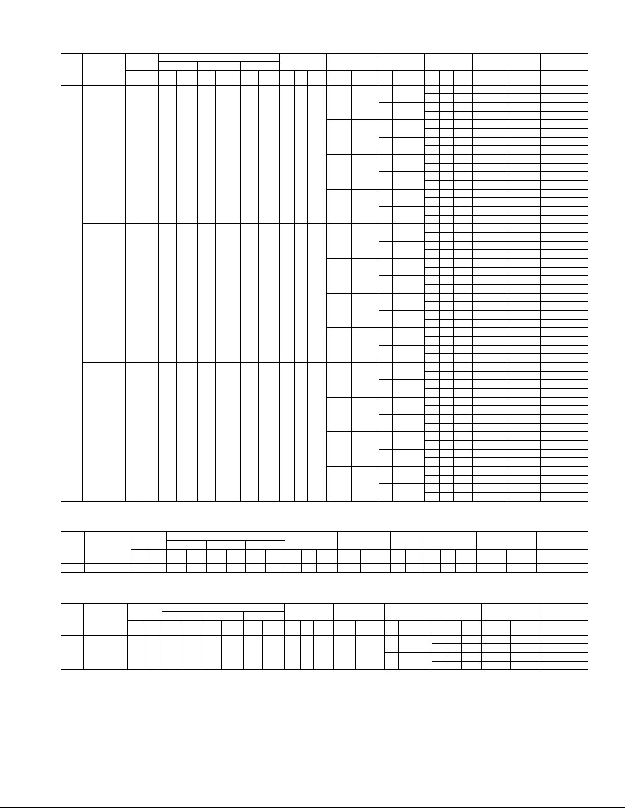
Table 2B — Electrical Data (Units With Optional Convenience Outlet) (cont)
UNIT
NOMINAL
SIZE
VO LTAGE
50HG
(3 Ph, 60 Hz)
208/230 187 253 16.7 130.0 16.7 130.0 22.4 184.0 4.01/41.5
020
VO LTAGE
RANGE
Min Max RLA LRA RLA LRA RLA LRA Qty Hp
460 414 506 9.0 70.0 9.0 70.0 10.7 90.0 4.01/40.7
575 518 633 7.0 55.0 7.0 55.0 9.3 73.0 4.01/40.7
COMPRESSOR
No. 1 No. 2 No. 3
OFM
ELECTRIC
FLA
(ea)
HEAT
kW FLA Hp FLA Qty Hp
5.0 16.7/15.2
——
7.5 24.2/22.0
5.0 16.7/15.2
19/25 52/ 60
7.5 24.2/22.0
5.0 16.7/15.2
38/50 104/120
7.5 24.2/22.0
5.0 16.7/15.2
56/75† 156/180
7.5 24.2/22.0
5.0 7.6
——
7.5 11.0
5.0 7.6
25 30
7.5 11.0
5.0 7.6
50 60
7.5 11.0
5.0 7.6
75 90
7.5 11.0
5.0 6.1
——
7.5 9.0
5.0 6.1
25 24
7.5 9.0
5.0 6.1
48 46
7.5 9.0
5.0 6.1
78 75
7.5 9.0
IFM
POWER
EXHAUST
FLA
(ea)
—— — 89/ 88 110/110 100/ 90
2 1.0 5.9 101/ 99 110/110 110/110
—— — 97/ 94 110/110 100/100
2 1.0 5.9 109/106 125/125 125/110
—— — 92/100 110/110 100/ 90
2 1.0 5.9 107/115 110/125 110/110
—— — 102/109 110/110 100/100
2 1.0 5.9 116/124 125/125 125/110
—— — 157/145 175/150 150/175
2 1.0 5.9 172/160 175/175 175/175
—— — 167/154 175/175 150/175
2 1.0 5.9 181/169 200/175 175/200
—— — 89/ 88† 110/110† 100/ 90†
2 1.0 5.9 101/ 99† 110/110† 110/110†
—— — 97/ 94† 110/110† 100/100†
2 1.0 5.9 109/106† 125/125† 125/110†
—— — 45 50 45
21.03.1 51 60 60
—— — 48 50 50
21.03.1 54 60 60
—— — 51 60 45
21.03.1 59 60 60
—— — 55 60 50
21.03.1 63 70 60
—— — 73 80 80
21.03.1 81 90 90
—— — 78 80 90
21.03.1 85 90 90
—— — 103 125 125
2 1.0 3.1 111 125 125
—— — 108 125 125
2 1.0 3.1 115 125 125
—— — 38 45 40
21.03.1 44 50 45
—— — 40 45 45
21.03.1 47 50 50
—— — 41 45 40
21.03.1 49 50 45
—— — 45 45 45
21.03.1 53 60 50
—— — 69 70 60
21.03.1 77 80 70
—— — 73 80 70
21.03.1 80 90 80
—— — 86 100 100
2 1.0 3.1 94 100 110
—— — 90 100 100
2 1.0 3.1 98 100 110
POWER
SUPPLY
MCA MOCP* FLA
DISCONNECT
SIZE
ELECTRIC HEAT BRANCH CIRCUIT FOR 208/240-V 75-kW ELECTRIC HEAT
UNIT
NOMINAL
SIZE
VO LTAGE
50HG
(3 Ph, 60 Hz)
020 208/240 187 253 NA NA NA NA NA NA NA NA NA 56/75 156/180 NA NA NA NA NA 156/180 175/200 200/225
VO LTAGE
RANGE
Min Max RLA LRA RL A LRA RLA LRA Qty Hp
COMPRESSOR
No. 1 No. 2 No. 3
OFM
ELECTRIC
FLA
(ea)
HEAT
kW FLA Hp FLA Qty Hp
IFM
POWER
EXHAUST
POWER
FLA
(ea)
SUPPLY
MCA MOCP* FLA
DISCONNECT
FEEDER CIRCUIT FOR 208/230-V UNIT WITH 75-kW ELECTRIC HEAT
UNIT
NOMINAL
SIZE
VO LTAGE
50HG
(3 Ph, 60 Hz)
020 208/230 187 253 16.7 130.0 16.7 130.0 22.4 184.0 4.01/41.5 56/75 156/180
See Legend and Notes on page 10.
VO LTAGE
RANGE
Min Max RLA LRA RLA LRA RLA LRA Qty Hp
COMPRESSOR
No. 1 No. 2 No. 3
OFM
ELECTRIC
FLA
(ea)
HEAT
kW FLA Hp FLA Qty Hp
IFM
5.0 16.7/15.2
7.5 24.2/22.0
POWER
EXHAUST
FLA
(ea)
—— — 183/205 200/225 200/225
2 1.0 5.9 198/220 200/225 225/250
—— — 193/214 200/225 225/250
2 1.0 5.9 207/229 225/250 225/250
POWER
SUPPLY
MCA MOCP* FLA
DISCONNECT
17
SIZE
SIZE
Page 18

Table 2B — Electrical Data (Units With Optional Convenience Outlet) (cont)
UNIT
NOMINAL
SIZE
VO LTAGE
50HG
(3 Ph, 60 Hz)
208/230 187 253 22.4 184.0 22.4 184.0 22.4 184.0 4.01/41.5
024
VO LTAGE
RANGE
Min Max RLA LRA RLA LRA RL A LRA Qty Hp
460 414 506 10.7 90.0 10.7 90.0 10.7 90.0 4.01/40.7
575 518 633 9.3 73.0 9.3 73.0 9.3 73.0 4.01/40.7
COMPRESSOR
No. 1 No. 2 No. 3
OFM
ELECTRIC
FLA
(ea)
HEAT
kW FLA Hp FLA Qty Hp
5.0 16.7/15.2
——
7.5 24.2/22.0
5.0 16.7/15.2
19/25 52/ 60
7.5 24.2/22.0
5.0 16.7/15.2
38/50 104/120
7.5 24.2/22.0
5.0 16.7/15.2
56/75† 156/180
7.5 24.2/22.0
5.0 7.6
——
7.5 11.0
5.0 7.6
25 30
7.5 11.0
5.0 7.6
50 60
7.5 11.0
5.0 7.6
75 90
7.5 11.0
5.0 6.1
——
7.5 9.0
5.0 6.1
25 24
7.5 9.0
5.0 6.1
48 46
7.5 9.0
5.0 6.1
78 75
7.5 9.0
IFM
POWER
EXHAUST
FLA
(ea)
—— — 101/ 99 110/110 110/110
2 1.0 5.9 112/111 125/125 125/125
—— — 109/106 125/125 125/110
2 1.0 5.9 120/118 125/125 150/125
—— — 101/100 110/110 110/110
2 1.0 5.9 112/115 125/125 125/125
—— — 109/109 125/125 125/110
2 1.0 5.9 120/124 125/125 150/125
—— — 157/145 175/150 150/175
2 1.0 5.9 172/160 175/175 175/175
—— — 167/154 175/175 150/175
2 1.0 5.9 181/169 200/175 175/200
—— — 101/ 99† 110/110† 110/110†
2 1.0 5.9 112/111† 125/125† 125/125†
—— — 109/106† 125/125† 125/110†
2 1.0 5.9 120/118† 125/125† 150/125†
—— — 48 50 50
21.03.1 54 60 60
—— — 52 60 60
21.03.1 58 60 60
—— — 51 60 50
21.03.1 59 60 60
—— — 55 60 60
21.03.1 63 70 60
—— — 73 80 80
21.03.1 81 90 90
—— — 78 80 90
21.03.1 85 90 90
—— — 103 125 125
2 1.0 3.1 111 125 125
—— — 108 125 125
2 1.0 3.1 115 125 125
—— — 42 50 45
21.03.1 48 50 50
—— — 45 50 50
21.03.1 51 60 60
—— — 42 50 45
21.03.1 49 50 50
—— — 45 50 50
21.03.1 53 60 60
—— — 69 70 60
21.03.1 77 80 70
—— — 73 80 70
21.03.1 80 90 80
—— — 86 100 100
2 1.0 3.1 94 100 110
—— — 90 100 100
2 1.0 3.1 98 100 110
POWER
SUPPLY
MCA MOCP* FLA
DISCONNECT
SIZE
ELECTRIC HEAT BRANCH CIRCUIT FOR 208/240-V 75-kW ELECTRIC HEAT
UNIT
NOMINAL
SIZE
VO LTAGE
50HG
(3 Ph, 60 Hz)
024 208/240 187 253 NA NA NA NA NA NA NA NA NA 56/75 156/180 NA NA NA NA NA 156/180 175/200 200/225
VO LTAGE
RANGE
Min Max RLA LRA RL A LRA RLA LRA Qty Hp
COMPRESSOR
No.1 No.2 No.3
OFM
ELECTRIC
FLA
(ea)
HEAT
kW FLA Hp FLA Qty Hp
IFM
POWER
EXHAUST
POWER
FLA
(ea)
SUPPLY
MCA MOCP* FLA
DISCONNECT
FEEDER CIRCUIT FOR 208/230-V UNIT WITH 75-kW ELECTRIC HEAT
UNIT
NOMINAL
SIZE
VO LTAGE
50HG
(3 Ph, 60 Hz)
024 208/230 187 253 22.4 184.0 22.4 184.0 22.4 184.0 4.01/41.5 56/75 156/180
See Legend and Notes on page 10.
VO LTAGE
RANGE
Min Max RLA LRA RLA LRA RLA LRA Qty Hp
COMPRESSOR
No. 1 No. 2 No. 3
OFM
ELECTRIC
FLA
(ea)
HEAT
kW FLA Hp FLA Qty Hp
IFM
5.0 16.7/15.2
7.5 24.2/22.0
POWER
EXHAUST
FLA
(ea)
—— — 183/205 200/225 200/225
2 1.0 5.9 198/220 200/225 225/250
—— — 193/214 200/225 225/250
2 1.0 5.9 207/229 225/250 225/250
POWER
SUPPLY
MCA MOCP* FLA
DISCONNECT
18
SIZE
SIZE
Page 19

Table 2B — Electrical Data (Units With Optional Convenience Outlet) (cont)
UNIT
NOMINAL
SIZE
VO LTAGE
50HG
(3 Ph, 60 Hz)
208/230 187 253 47.1 245.0 47.1 245.0 ——6.01/41.5
028
VO LTAGE
RANGE
Min Max RLA LRA RLA LRA RLA LRA Qty Hp
460 414 506 19.6 125.0 19.6 125.0 ——6.01/40.7
575 518 633 15.8 100.0 15.8 100.0 ——6.01/40.7
COMPRESSOR
No. 1 No. 2 No. 3
OFM
ELECTRIC
FLA
(ea)
HEAT
kW FLA Hp FLA Qty Hp
——
19/25 52/ 60
38/50 104/120
56/75† 156/180
——
25 30
50 60
75 90
——
25 24
48 46
78 75
IFM
7.5 24.2/22.0
10.0 30.8/28.0
7.5 24.2/22.0
10.0 30.8/28.0
7.5 24.2/22.0
10.0 30.8/28.0
7.5 24.2/22.0
10.0 30.8/28.0
7.5 11.0
10.0 14.0
7.5 11.0
10.0 14.0
7.5 11.0
10.0 14.0
7.5 11.0
10.0 14.0
7.5 9.0
10.0 11.0
7.5 9.0
10.0 11.0
7.5 9.0
10.0 11.0
7.5 9.0
10.0 11.0
POWER
EXHAUST
FLA
(ea)
—— — 144/142 175/175 150/150
2 1.0 5.9 156/154 200/200 175/175
—— — 151/148 175/175 175/175
2 1.0 5.9 163/160 200/200 175/175
—— — 144/142 175/175 150/150
2 1.0 5.9 156/154 200/200 175/175
—— — 151/148 175/175 175/175
2 1.0 5.9 163/160 200/200 175/175
—— — 167/154 175/175 150/175
2 1.0 5.9 181/169 200/200 175/200
—— — 175/161 175/175 175/175
2 1.0 5.9 190/176 200/200 175/200
—— — 144/142† 175/175† 150/150†
2 1.0 5.9 156/154† 200/200† 175/175†
—— — 151/148† 175/175† 175/175†
2 1.0 5.9 163/160† 200/200† 175/175†
—— — 62 80 70
21.03.1 69 80 70
—— — 65 80 70
21.03.1 72 90 80
—— — 62 80 70
21.03.1 69 80 70
—— — 65 80 70
21.03.1 72 90 80
—— — 78 80 90
21.03.1 85 90 90
—— — 81 90 90
2 1.0 3.1 89 100 100
—— — 108 125 125
2 1.0 3.1 115 125 125
—— — 111 125 125
2 1.0 3.1 119 125 150
—— — 52 60 60
21.03.1 58 70 60
—— — 54 60 60
21.03.1 60 70 70
—— — 52 60 60
21.03.1 58 70 60
—— — 54 60 60
21.03.1 60 70 70
—— — 73 80 70
21.03.1 80 90 80
—— — 75 80 70
21.03.1 83 90 80
—— — 90 100 100
2 1.0 3.1 98 100 110
—— — 93 100 100
2 1.0 3.1 100 110 110
POWER
SUPPLY
MCA MOCP* FLA
DISCONNECT
SIZE
ELECTRIC HEAT BRANCH CIRCUIT FOR 208/240-V 75-kW ELECTRIC HEAT
UNIT
NOMINAL
SIZE
VO LTAGE
50HG
(3 Ph, 60 Hz)
028 208/240 187 253 NA NA NA NA NA NA NA NA NA 56/75 156/180 NA NA NA NA NA 156/180 175/200 200/225
VO LTAGE
RANGE
Min Max RLA LRA RL A LRA RLA LRA Qty Hp
COMPRESSOR
No. 1 No. 2 No. 3
OFM
ELECTRIC
FLA
(ea)
HEAT
kW FLA Hp FLA Qty Hp
IFM
POWER
EXHAUST
POWER
FLA
(ea)
SUPPLY
MCA MOCP* FLA
DISCONNECT
FEEDER CIRCUIT FOR 208/230-V UNIT WITH 75-kW ELECTRIC HEAT
UNIT
NOMINAL
SIZE
VO LTAGE
50HG
(3 Ph, 60 Hz)
028 208/230 187 253 47.1 245.0 47.1 245.0 ——6.01/41.5 56/75 156/180
See Legend and Notes on page 10.
VO LTAGE
RANGE
Min Max RLA LRA RLA LRA RLA LRA Qty Hp
COMPRESSOR
No. 1 No. 2 No. 3
OFM
ELECTRIC
FLA
(ea)
HEAT
kW FLA Hp FLA Qty Hp
IFM
7.5 24.2/22.0
10.0 30.8/28.0
POWER
EXHAUST
FLA
(ea)
—— — 193/214 200/225 225/250
2 1.0 5.9 207/229 225/250 225/250
—— — 201/221 225/225 225/250
2 1.0 5.9 216/236 225/250 250/300
POWER
SUPPLY
MCA MOCP* FLA
DISCONNECT
19
SIZE
SIZE
Page 20

LEGEND
EQUIP —
GND —
NEC —
TB —
NOTE: The maximum wire size for TB1 is 2/0.
Equipment
Ground
National Electrical Code
Terminal Board
Fig. 12 — Field Power Wiring Connections
REMOVABLE JUMPER
RC
RH
R
TB4
1
THERMOSTAT ASSEMBLY
Y1 Y2
Y1 Y2
2
W1 W2 G CLX
W1 W2 G C X
45
3
6
Fig. 13 — Field Control Thermostat Wiring
T-55 SPT
T1
TB3
Space Temperature Sensor
SPT —
7
T2
9
8
T-56 SPT
TH
COM
Fig. 14 — Field Control Space
Temperature Sensor Wiring
Set heat anticipator settings as shown in Table 3.
Table 3 — Heat Anticipator Settings
UNIT SIZE
50HG
014
016-028
STAGE 1
ELECTRIC
HEAT (kW)
15 0.2 0.2 0.2 0.2 0.2 0.2
25 0.2 0.2 0.2 0.4 0.4 0.4
50 0.4 0.2 0.2 0.8 0.4 0.4
25 0.2 0.2 0.2 0.4 0.4 0.4
50 0.4 0.2 0.2 0.8 0.4 0.4
75 0.4 0.2 0.2 0.8 0.4 0.4
(W1) ON
Vo lt ag e Vo lt ag e
208/240 480 600 208/240 480 600
STAGES 1 AND 2
8
7
SN
(W1 and W2) ON
3. Remove the bracket holding the bottom half of the hood
in the shipping position. Remove the hood bottom half
and filters (or manual dampers on units so equipped)
from outdoor section.
NOTE: On units without economizers, the compone nts
are attached to the unit basepan. To access the components, remove the panel below the outdoor air intake
section.
4. Remove inner filter track from shipping position in outdoor section. Position inner filter track so the track is facing outward from the unit. Install the filter track with
4 screws provided.
5. Apply seal strip (provided) to back flange of both hood
sides where hood side connects to the unit back panel.
See Fig. 16.
6. Apply seal strip (provided) to top flange of both hood
sides where hood sides connect to the hood top panels.
See Fig. 16.
7. Install hood sides to the back panels using the screws from
Step 2. The sloped flanges point outward. The drip edges
of the side panels should face outward as well. The filter
guides should face inward to hold the filters in place. See
Fig. 16.
8. Apply seal strip along the entire length of the bottom
flange of the hood top. See Fig. 16.
9. Install the bottom part of the hood top using 4 screws provided. See Fig. 16.
10. Remove the packaging from filters (3) and install into the
filter tracks. Slide the filters to the sides then place the last
filter into the center of the filter track.
NOTE: For units with manual dampers, replace the end fi lters
with the manual dampers. Install the filter in the center
between the manual dampers.
11. Install the filter retainer track along the bottom edge of the
outdoor air hood using 4 screws provided. See Fig. 16.
12. Install top section of the outdoor air hood using 9 screws
provided. See Fig. 16. See Fig. 17 for a picture of the
assembled outdoor air hood.
NOTE: For filter removal, remove the four screws holding the
filter retainer. The filters can then be removed, cleaned, or
replaced. Install the filters by reversing the procedure.
MANUAL DAMPER ASSEMBL Y — For units equipped
with manual dampers, the assembly process is similar to the outdoor air hood for units with economizers. There are two slide
dampers shipped with the unit to allow for manual setting of the
outside air volume. When assembling the hood, place one of the
manual slide dampers in each of the end positions and the remaining filter in the center position. The manual da mpers can
then be moved to the appropriate position and then locked into
place using the screws mounted in the adjustment slots. See
Fig. 18.
HOOD TOP
(TOP HALF)
HOOD
SIDE
HOOD
SIDE
HOOD TOP
(BOTTOM HALF)
Settings may be changed slightly to provide a greater degree
of comfort for a particular installation.
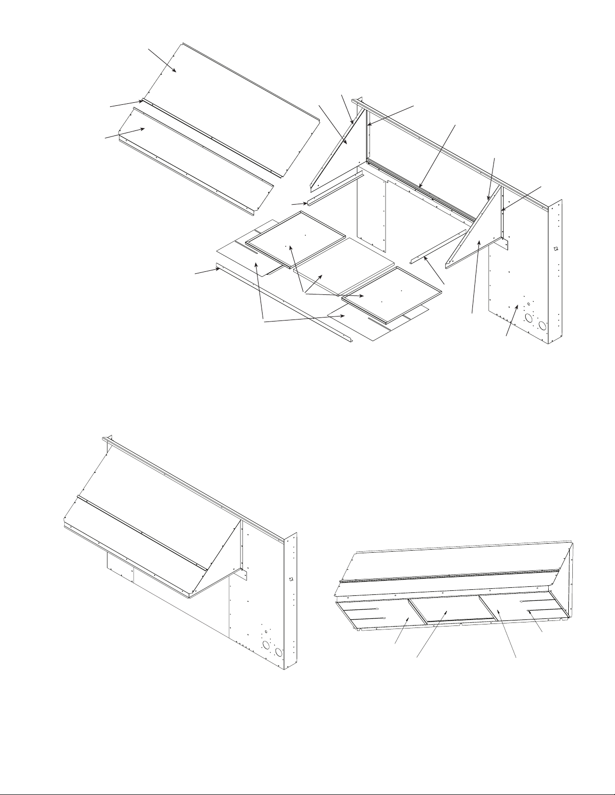
Step 8 — Install Outdoor Air Hood —
Perform the
following procedure to install the outdoor-air hood:
1. Remove blank panel from re turn end of unit (hood section). Save the screws. See Fig. 15 for shipping location
of components.
2. Hood sides are fastened to sides of outdoor ai r opening.
Remove the hood sides and save the screws (3 each side).
20
RETURN AIR
SECTION
Fig. 15 — Outdoor-Air Hood Compartment
Shipping Location
Page 21
SEAL
STRIP
LOCATION
BOTTOM
HOOD
SECTION
TOP HOOD
SECTION
FILTER
RETAINER
FILTER
GUIDE
HOOD
SIDE
FILTER
ADD
SEAL
STRIP
ADD
SEAL
STRIP
INNER
FILTER
TRACK
FILTER
GUIDE
ADD
SEAL
STRIP
ADD
SEAL
STRIP
MANUAL
DAMPER
(IF EQUIPPED)
NOTE: Units with manual damper only use one filter.
Fig. 16 — Outdoor Air Hood Details
HOOD
SIDE
UNIT
BACK
PANEL
Fig. 17 — Outdoor Air Hood Assembled
MOVEABLE DAMPER
AIR FILTER POSITION
21
LOCKING SCREW
MOVEABLE DAMPER
Fig. 18 — Manual Damper Details
Page 22

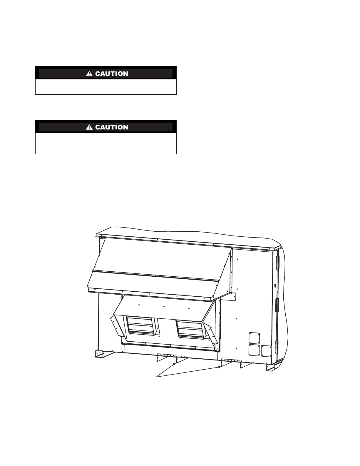
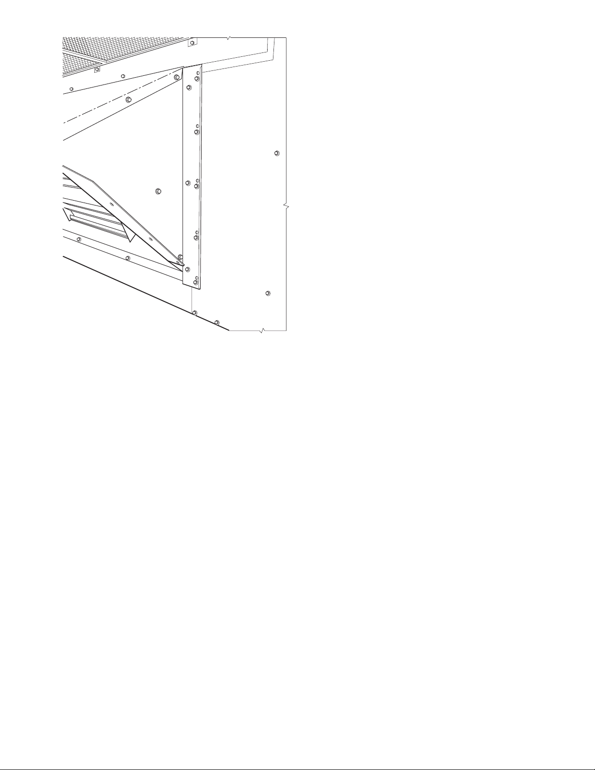
Step 9 — Position Optional Power Exhaust or
Barometric Relief Damper Hood —
power exhaust or barometric relief dampers are shipped
assembled and tilted back into the unit fo r shipping. B rackets and extra screws are shipped in shrink wrap around the
dampers.
1. Remove 9 screws holding each damper assembly in
place. See Fig. 19. Each damper assembly is secured with
3 screws on each side and 3 screws along the bottom.
Save screws.
Be careful when tilting blower assembly. Hoods and blowers are heavy and can cause injury if dropped.
2. Pivot the damper assembly outward until top edge of
damper assembly rests against inside wall of unit.
3. Secure each damper assembly to unit with 6 screws
across top (3 screws provided) and bottom (3 screws
from Step 1) of damper.
4. With screws saved from Step 1, install brackets on each
side of damper assembly . See Fig. 20.
5. Remove tape from damper blades.
Step 10 — Non-Fused Disconnect —
for the factory-installed non-fused disconnect is shipped inside
the unit to prevent the handle from damage during shipping.
Follow these steps to complete installation of the handle.
The optional
The handle
BE SURE POWER IS SHUT OFF TO THE UNIT FROM
THE BUILDING POWER SUPPLY.
1. Open the control box access door.
2. Remove the small cove r plate located on the unit corner
post near the control section.
3. Remove the inner control box cover. The handle and shaft
are located in a plastic bag at the bottom of the control
box.
4. Insert the square shaft into the disconnect with the pins
vertical. On the 100 amp disconnect the shaft is keyed
into the disconnect and can only be installed one way
with the pins vertical.
5. Insert the handle through the corner post and onto the
shaft with the handle positioned so that “OFF” is on top.
6. Rotate the handle to the “ON” position to lock the pins
into the handle.
7. From the inside of the corner post, attach the handle
mounting screws to the handle. Slide the shaft fully into
the handle and tighten the set screws(s) on the disconnect
to lock the shaft. Tighten the screws that attach the handle
to the corner post.
8. Rotate the handle back to the “OFF” p osit ion.
9. Replace all panels and doors .
10. Restore power to unit.
Fig. 19 — Power Exhaust or Barometric Relief Damper Mounting Details
22
Page 23
Step 11 — Install All Accessories —
the factory-installed options have been adjusted, install all
field-installed accessor ies. Refer to the accessory installation
instructions included with e ach accessory. Consult the Carrier
Price Pages for accessory package numbers for particular
applications. The available field-installed accessories for the
Centurion units are:
• economizer
• power exhaust
• barom e tric relief damper
• 14-in. roof curb
• 24-in. roof curb
• electric heaters
• enthalpy control
• differential enthalpy control
• plugged filter indicator
• carbon dioxide detector
• smoke detector
• filter status switch
• fan status switch
• condenser hail guard
• horizontal duct accessory
• thermostats
• tw o-position damper
After all of
Fig. 20 — Bracket and Hood Positioning
23
Page 24

Copyright 2003 Carrier Corporation
Manufacturer reserves the right to discontinue, or change at any time, specifications or designs without notice and without incurring obligations.
Book 1 4
Ta b 1 b 6b
PC 111 Catalog No. 535-00092 Printed in U.S.A. Form 50HG-7SI Pg 24 11-03 Replaces: 50HG-3SI
 Loading...