

Page 1
WeatherMaster
50HC14
Single Package Rooftop Cooling Only Unit
®
with Puron
(R-410A) Refrigerant
Installation Instructions
50HC units for installation in the United States contain use of Carrier's Staged Air Volume (SAV™) 2-speed
indoor fan control system. This complies with the U.S. Department of Energy (DOE) efficiency standard of
2018.
50HC units for installation outside the United States may or may not contain use of the SAV 2-speed indoor
fan control system as they are not required to comply with the U.S. Department of Energy (DOE) efficiency
standard of 2018.
For specific details on operation of the Carrier SAV 2-speed indoor fan system refer to the Variable
Frequency Drive (VFD) Factory-Installed Option 2-Speed Motor Control Installation, Setup, and
Troubleshooting manual.
®
CONTENTS
Page
SAFETY CONSIDERATIONS. . . . . . . . . . . . . . . . . . . . 1-6
Rated Indoor Airflow (cfm) . . . . . . . . . . . . . . . . . . . . . . ..2
INSTALLATION . . . . . . . . . . . . . . . . . . . . . . . . . . . . . . . 6-63
Jobsite Survey . . . . . . . . . . . . . . . . . . . . . . . . . . . . . . . . . . . 6
Step 1 — Plan for Unit Location . . . . . . . . . . . . . . . . . . 6
Step 2 — Plan for Sequence of Unit Installation . 6
Step 3 — Inspect Unit . . . . . . . . . . . . . . . . . . . . . . . . . . . . 7
Step 4 — Provide Unit Support. . . . . . . . . . . . . . . . . . . 7
Step 5 — Field Fabricate Ductwork. . . . . . . . . . . . . . . 9
Step 6 — Rig and Place Unit . . . . . . . . . . . . . . . . . . . . . 9
Step 7 — Convert to Horizontal and Connect
Ductwork . . . . . . . . . . . . . . . . . . . . . . . . . . . . . . . . . . . . . 11
Step 8 — Install Outside Air Hood . . . . . . . . . . . . . . . 11
Step 9 — Install External Condensate Trap and
Line . . . . . . . . . . . . . . . . . . . . . . . . . . . . . . . . . . . . . . . . . . 13
Step 10 — Make Electrical Connections . . . . . . . . . 13
Electric Heaters . . . . . . . . . . . . . . . . . . . . . . . . . . . . . . . . . 21
Single Point Boxes . . . . . . . . . . . . . . . . . . . . . . . . . . . . . . 21
Humidi-MiZer
EconoMi$er
Low Ambient Control (Factory Option) . . . . . . . . . 37
Staged Air Volume (SAV) with Variable Frequency
Drive (Factory Option) . . . . . . . . . . . . . . . . . . . . . . . 37
ComfortLink Controls (Factory Option) . . . . . . . . . 37
PremierLink Controller (Factory Option) . . . . . . . . 42
Supply Air Temperature Sensor . . . . . . . . . . . . . . . . . 45
Field Connections . . . . . . . . . . . . . . . . . . . . . . . . . . . . . . 45
Economizer Controls . . . . . . . . . . . . . . . . . . . . . . . . . . . 48
RTU Open Control System . . . . . . . . . . . . . . . . . . . . . . 52
Field Connections . . . . . . . . . . . . . . . . . . . . . . . . . . . . . . 56
Communication Wiring — Protocols . . . . . . . . . . . . 58
Local Access. . . . . . . . . . . . . . . . . . . . . . . . . . . . . . . . . . . . 59
Outdoor Air Enthalpy Control . . . . . . . . . . . . . . . . . . . 60
Smoke Detectors. . . . . . . . . . . . . . . . . . . . . . . . . . . . . . . . 61
Step 11 — Adjust Factory-Installed Options. . . . . 62
Step 12 — Install Accessories. . . . . . . . . . . . . . . . . . . 62
Pre-Start and Start-up . . . . . . . . . . . . . . . . . . . . . . . . . . . 62
START-UP CHECKLIST . . . . . . . . . . . . . . . . . CL-1, CL-2
®
System Control Connections . . . . 22
®
X (Factory-Installed Option) . . . . . . . 24
SAFETY CONSIDERATIONS
Improper installation, adjustment, alteration, service, maintenance, or use can cause explosion, fire, electrical shock or
other conditions which may cause personal injury or property
damage. Consult a qualified installer, service agency, or your
distributor or branch for information or assistance. The qualified installer or agency must use factory-authorized kits or accessories when modifying this product. Refer to the individual
instructions packaged with the kits or accessories when
installing.
Follow all safety codes. Wear safety glasses and work
gloves. Use quenching cloths for brazing operations and have a
fire extinguisher available. Read these instructions thoroughly
and follow all warnings or cautions attached to the unit. Consult local building codes and appropriate national electrical
codes (in USA, ANSI/NFPA 70, National Electrical Code
(NEC); in Canada, CSA C22.1) for special requirements.
It is important to recognize safety information. This is the
safety-alert symbol . When you see this symbol on the unit
and in instructions or manuals, be alert to the potential for personal injury.
Understand the signal words DANGER, WARNING, CAUTION, and NOTE. These words are used with the safety-alert
symbol. DANGER identifies the most serious hazards which
will result in severe personal injury or death. WARNING signifies hazards which could result in personal injury or death.
CAUTION is used to identify unsafe practices, which may result in minor personal injury or product and property damage.
NOTE is used to highlight suggestions which will result in enhanced installation, reliability, or operation.
WARNING
ELECTRICAL SHOCK HAZARD
Failure to follow this warning could cause personal injury
or death.
Before performing service or maintenance operations on
unit, always turn off main power switch to unit and install
lock(s) and lockout tag(s). Unit may have more than one
power switch.
Manufacturer reserves the right to discontinue, or change at any time, specifications or designs without notice and without incurring obligations.
Catalog No. 04-53500157-01 Printed in U.S.A. Form 50HC-14-02SI Pg 1 12-17 Replaces: 50HC-14-01SI
Page 2
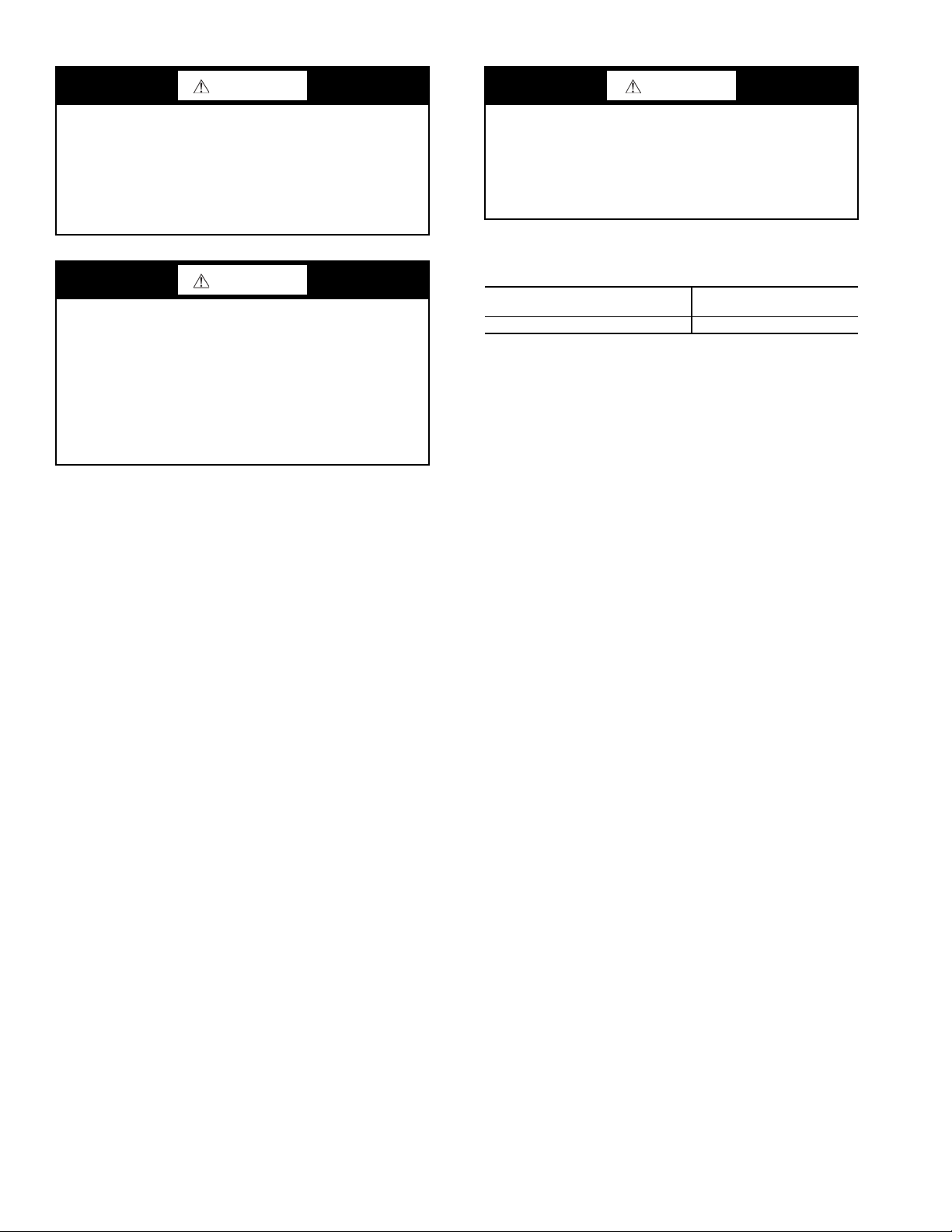
WARNING
CAUTION
UNIT OPERATION AND SAFETY HAZARD
Failure to follow this warning could cause personal injury,
death and/or equipment damage.
®
Puron
(R-410A) refrigerant systems operate at higher
pressures than standard R-22 systems. Do not use R-22 service equipment or components on Puron refrigerant equipment.
WARNING
PERSONAL INJURY AND ENVIRONMENTAL
HAZARD
Failure to follow this warning could cause personal injury
or death.
Relieve pressure and recover all refrigerant before system
repair or final unit disposal.
Wear safety glasses and gloves when handling refrigerants.
Keep torches and other ignition sources away from refrigerants and oils.
CUT HAZARD
Failure to follow this caution may result in personal injury.
Sheet metal parts may have sharp edges or burrs. Use care
and wear appropriate protective clothing, safety glasses and
gloves when handling parts and servicing air-conditioning
equipment.
Rated Indoor Airflow (cfm) — The table below lists
the rated indoor airflow used for the AHRI efficiency rating for
the units covered in this document.
MODEL NUMBER
50HC*D/E/G14 4375
FULL LOAD AIRFLOW
(CFM)
2
Page 3
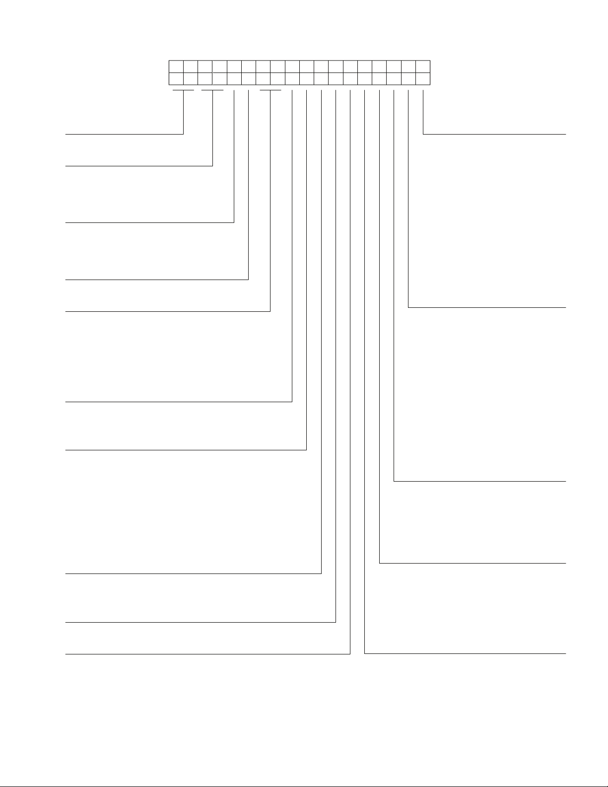
50HCBD14A2A6A0A3B0
Cooling Tons
14 - 12.5 ton
1
Example:
Position: 2 3 4 5 6 7 8 9
10
11 12 13 14 15 16 17 18
Heat Options
- - None (Field Installed Accessory)
A = Low Electric Heat
B = Medium Electric Heat
C = High Electric Heat
Sens or Options
A = None
B = RA Smoke Detector
C = SA Smoke Detector
D = RA + SA Smoke Detector
E = CO
2
F = RA Smoke Detector and CO
2
G = SA Smoke Detector and CO
2
H = RA + SA Smoke Detector and CO
2
Indoor Fan Options
1 = Standard Static Option - Belt Dirve
2 = Medium Static Option - Belt Drive
C = High Static Option with High Efficency Motor - Belt Drive
Coil Options (RTPF) (Outdoor - Indoor - Hail Guard)
A = Al/Cu - Al/Cu
B = Precoat Al/Cu - Al/Cu
C = E-coat Al/Cu - Al/Cu
D = E-coat Al/Cu - E-coat Al/Cu
E = Cu/Cu - Al/Cu
F = Cu/Cu - Cu/Cu
M = Al/Cu -Al/Cu — Louvered Hail Guard
N = Precoat Al/Cu - Al/Cu — Louvered Hail Guard
P = E-coat Al/Cu - Al/Cu — Louvered Hail Guard
Q = E-coat Al/Cu - E-coat Al/Cu — Louvered Hail Guard
R = Cu/Cu - Al/Cu — Louvered Hail Guard
S = Cu/Cu - Cu/Cu — Louvered Hail Guard
Voltage
1 = 575/3/60
5 = 208-230/3/60
6 = 460/3/60
Design Revision
A = Factory Design Revision
Base Unit Controls
0 = Electro-mechanical Controls Can be used with W7212
EconoMi$er IV (Non-Fault Detection and Diagnostic)
1 = PremierLink Controller
2 = RTU Open Multi-Protocol Controller
6 = Electro-mechanical with 2-speed fan and W7220
Econo controller Controls. Can be used with W7220
EconoMi$er X (with Fault Detection and Diagnostic)
D = ComfortLink Controls
Intake / Exhaust Options
A = None
B = Temperature Economizer w/ Barometric Relief
F = Enthalpy Economizer w/ Barometric Relief
K = 2-Position Damper
U = Low Leak Temperature Economizer
w/ Barometric Relief
W = Low Leak Enthalpy Economizer w/ Barometric Relief
Service Options
0 = None
1 = Unpowered Convenience Outlet
2 = Powered Convenience Outlet
3 = Hinged Panels
4 = Hinged Panels and
Unpowered Convenience Outlet
5 = Hinged Panels and
Powered Convenience Outlet
C = Foil Faced Insulation
D = Foil Faced Insulation with
Unpowered Convenience Outlet
E = Foil Faced Insulation with
Powered Convenience Outlet
F = Foil Faced Insulation & Hinged Panels
G = Foil Faced Insulation & Hinged Panels
with Unpowered Convenience Outlet
H = Foil Faced Insulation & Hinged Panels
with Powered Convenience Outlet
Factory Assigned
0 = Standard
1 = LTL
Electrical Options
A = None
B = HACR Breaker
C = Non-Fused Disconnect
D = Thru-The-Base Connections
E = HACR and Thru-The-Base Connections
F = Non-Fused Disconnect and
Thru-The-Base Connections
G = 2-Speed Indoor Fan (VFD) Controller
H = 2-Speed Fan Controller (VFD) and HACR
J = 2-Speed Fan Controller (VFD) and
Non-Fused Disconnect
K = 2-Speed Fan Controller (VFD) and
Thru-The-Base Connections
L = HACR w/ Thru-The-Base &
2-Speed Fan Controller (VFD)
M = 2-Speed Fan Controller (VFD) with
Non-Fused Disconnect and
Thru-The-Base Connections
Refrig. Syste ms Options
D = Two stage cooling models
E = Two stage cooling models with Humidi-MiZer
G = Two stage cooling models with
MotorMaster Low Ambient Controller
Model Series - WeatherMaster
®
HC - High Efficiency
Unit Heat Type
50 - Electric Heat
Packaged Rooftop
Fig. 1 — 50HC 14 Model Number Nomenclature (Example)
3
Page 4
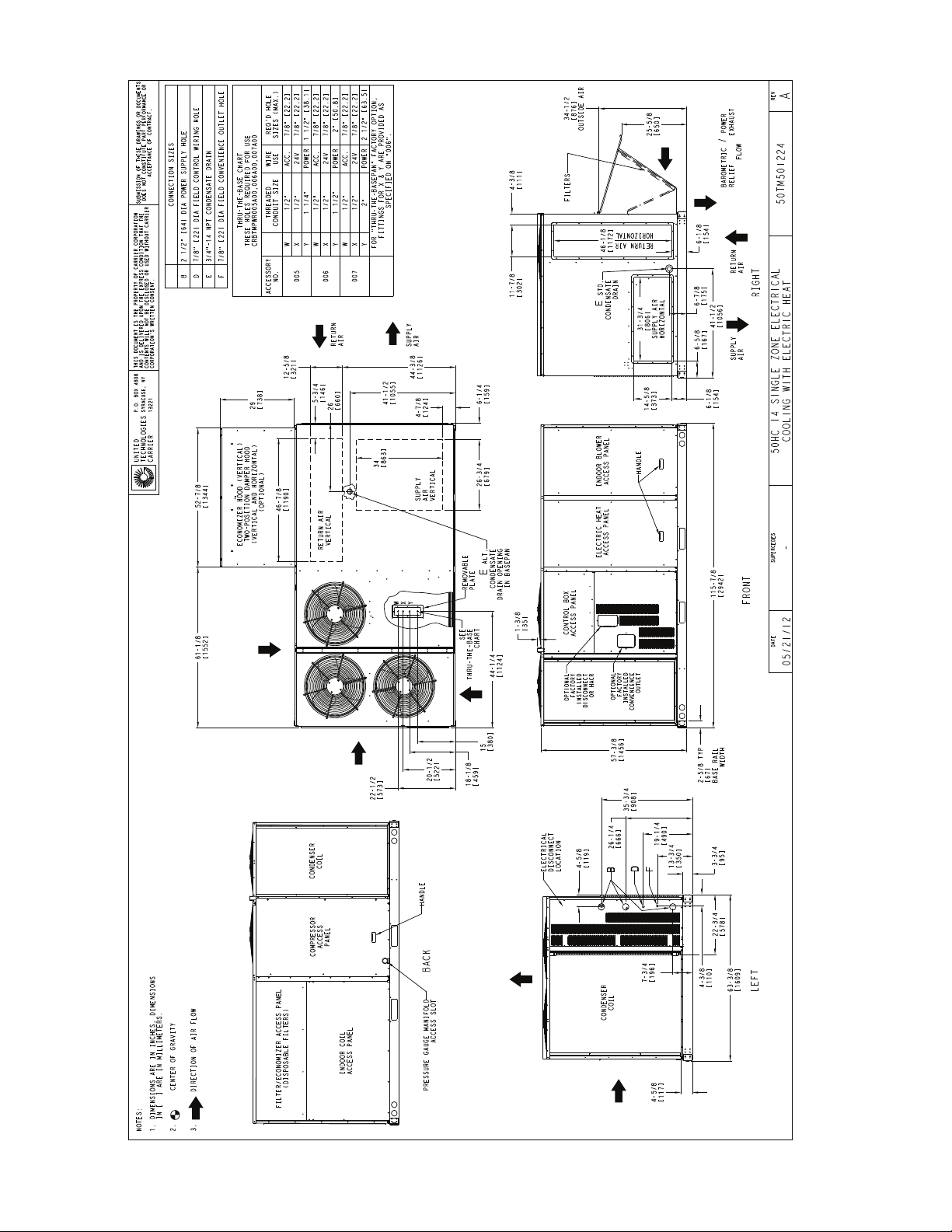
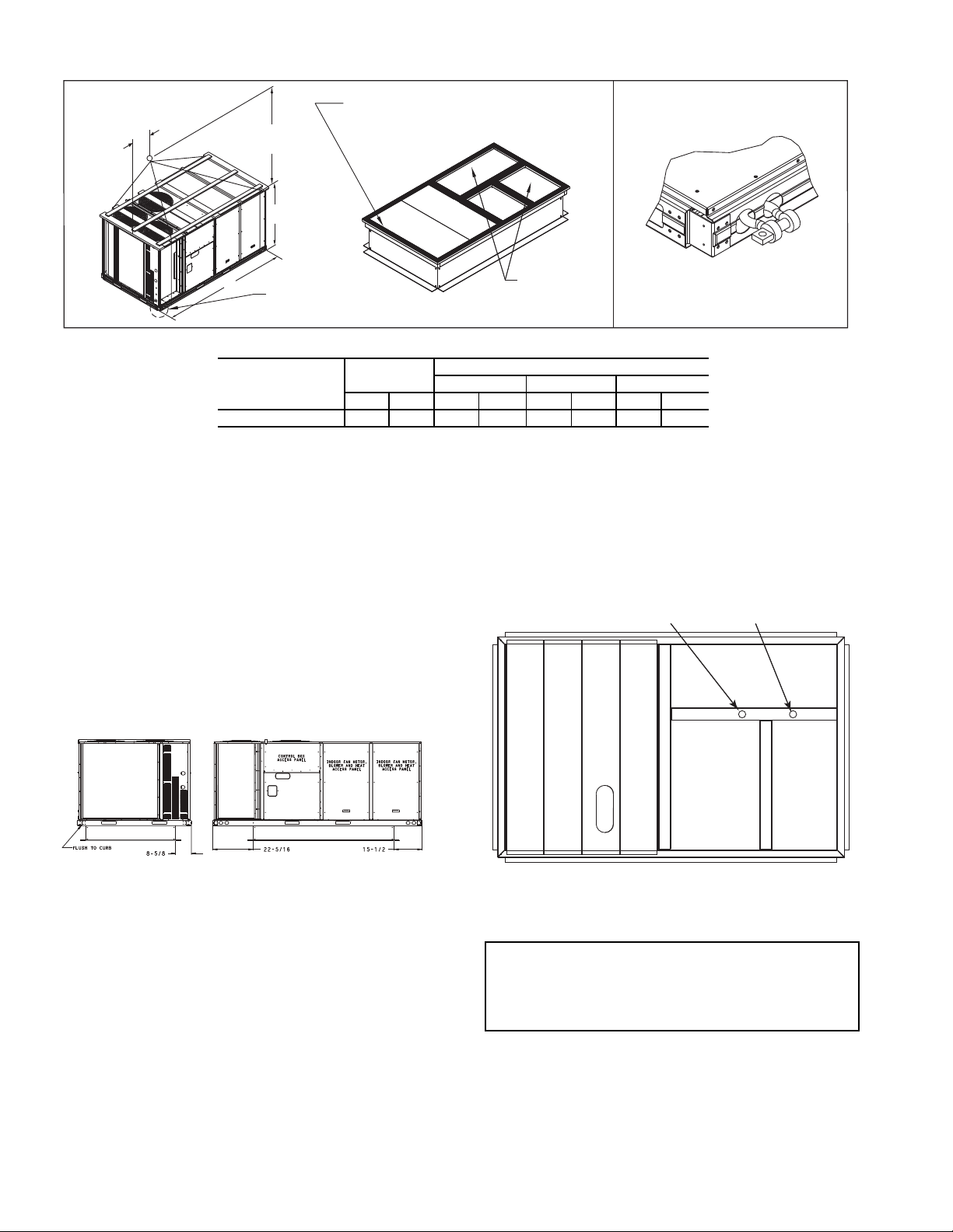
Fig. 2 — Unit Dimensional Drawing — 14 Size Unit
4
Page 5
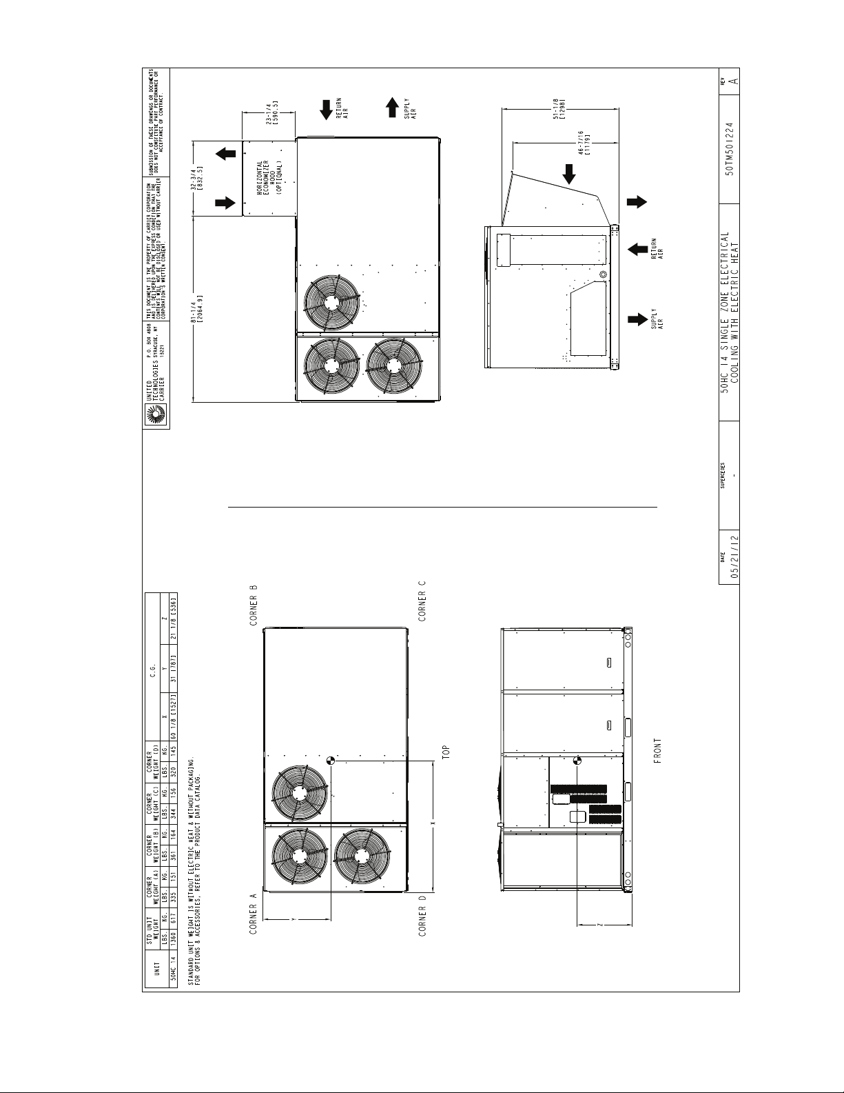
HORIZONTAL ECONOMIZER
VERTICAL ECONOMIZER
Fig. 2 — Unit Dimensional Drawing — 14 Size Unit (cont)
5
Page 6
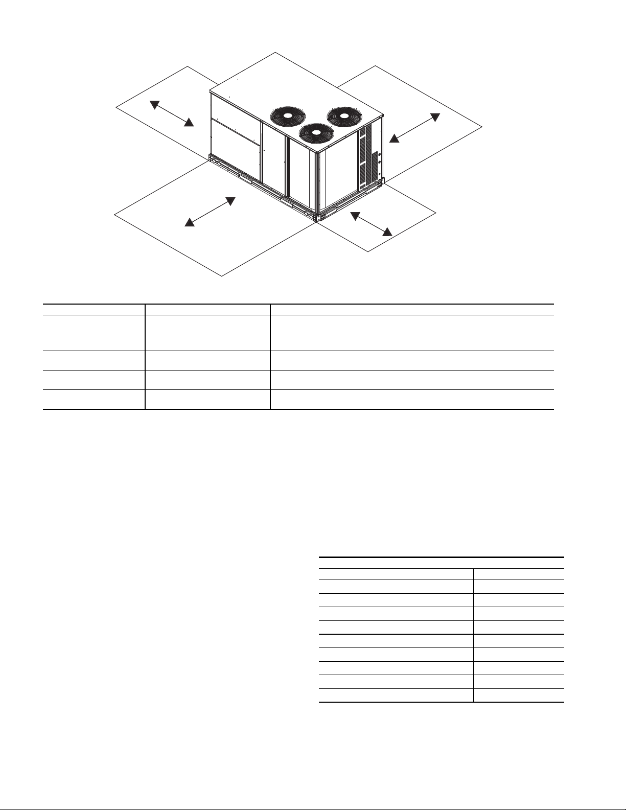
NOTE: Unit not designed to have overhead obstruction. Contact Application Engineering for guidance on any application planning overhead
obstruction or for vertical clearances.
LOCATION DIMENSION CONDITION
A
48-in. (1219 mm)
18-in. (457 mm)
18-in. (457 mm)
12-in. (305 mm)
Unit disconnect is mounted on panel
No disconnect, convenience outlet option
Recommended service clearance
Minimum clearance
B
42-in. (1067 mm)
36-in. (914 mm)
Surface behind servicer is grounded (e.g., metal, masonry wall)
Surface behind servicer is electrically non-conductive (e.g., wood, fiberglass)
C
36-in. (914 mm)
18-in. (457 mm)
Side condensate drain is used
Minimum clearance
D
42-in. (1067 mm)
36-in. (914 mm)
Surface behind servicer is grounded (e.g., metal, masonry wall, another unit)
Surface behind servicer is electrically non-conductive (e.g., wood, fiberglass)
C
D
B
A
Fig. 3 — Service Clearance Dimensional Drawing
INSTALLATION
Jobsite Survey —
installation.
1. Consult local building codes and the NEC (National
Electrical Code) ANSI/NFPA 70 for special installation
requirements.
2. Determine unit location (from project plans) or select unit
location.
3. Check for possible overhead obstructions which may interfere with unit lifting or rigging.
Complete the following checks before
Step 1 — Plan for Unit Location — Select a loca-
tion for the unit and its support system (curb or other) that provides for at least the minimum clearances required for safety.
This includes the clearance to combustible surfaces, unit performance and service access below, around and above unit as
specified in unit drawings. See Fig. 3.
NOTE: Consider also the effect of adjacent units.
Unit may be installed directly on wood flooring or on Class
A, B, or C roof-covering material when roof curb is used.
Do not install unit in an indoor location. Do not locate air inlets near exhaust vents, relief valves, or other sources of contaminated air.
Although unit is weatherproof, avoid locations that permit
water from higher level runoff and overhangs to fall onto the
unit.
6
Select a unit mounting system that provides adequate height
to allow installation of condensate trap per requirements. Refer
to Step 9 — Install External Condensate Trap and Line for required trap dimensions.
ROOF MOUNT — Check building codes for weight distribution requirements. Unit operating weight is shown in
Table 1.
Table 1 — Operating Weights
50HC**14
COMPONENT UNITS LB (KG)
Base Unit
Economizer
Vertical
Horizontal
Humidi-MiZer System
Powered Outlet
Curb
14-in. (356 mm)
24-in. (610 mm)
1360 (617)
103 (47)
242 (110)
90 (41)
35 (16)
180 (82)
255 (116)
Step 2 — Plan for Sequence of Unit Installation —
ferent sequences for the steps of unit installation. For example,
on curb-mounted units, some accessories must be installed on
the unit before the unit is placed on the curb. Review the following for recommended sequences for installation steps.
The support method used for this unit will dictate dif-
Page 7

CURB-MOUNTED INSTALLATION
Install curb
Install field-fabricated ductwork inside curb
Install accessory thru-base service connection package (affects curb and unit) (refer to accessory installation instructions
for details)
Prepare bottom condensate drain connection to suit planned
condensate line routing (refer to Step 9 for details)
Rig and place unit
Install outdoor air hood
Install condensate line trap and piping
Make electrical connections
Install other accessories
PAD-MOUNTED INSTALLATION
Prepare pad and unit supports
Check and tighten the bottom condensate drain connection
plug
Rig and place unit
Convert unit to side duct connection arrangement
Install field-fabricated ductwork at unit duct openings
Install outdoor air hood
Install condensate line trap and piping
Make electrical connections
Install other accessories
FRAME-MOUNTED INSTALLATION — Frame-mounted applications generally follow the sequence for a curb installation. Adapt as required to suit specific installation plan.
Step 3 — Inspect Unit — Inspect unit for transporta-
tion damage. File any claim with transportation agency.
Confirm before installation of unit that voltage, amperage
and circuit protection requirements listed on unit data plate
agree with power supply provided.
On units with hinged panel option, check to be sure all
latches are snug and in closed position.
Locate the carton containing the outside air hood parts; see
Fig. 11 and 12. Do not remove carton until unit has been rigged
and located in final position.
Step 4 — Provide Unit Support
ROOF CURB MOUNT — Accessory roof curb details and
dimensions are shown in Fig. 4. Assemble and install accessory roof curb in accordance with instructions shipped with the
curb.
NOTE: The gasketing of the unit to the roof curb is critical for
a watertight seal. Install gasket supplied with the roof curb as
shown in Fig. 4. Improperly applied gasket can also result in
air leaks and poor unit performance.
Curb should be level. This is necessary for unit drain to
function properly. Unit leveling tolerances are show in Fig. 5.
Refer to Accessory Roof Curb Installation Instructions for additional information as required.
7
Page 8
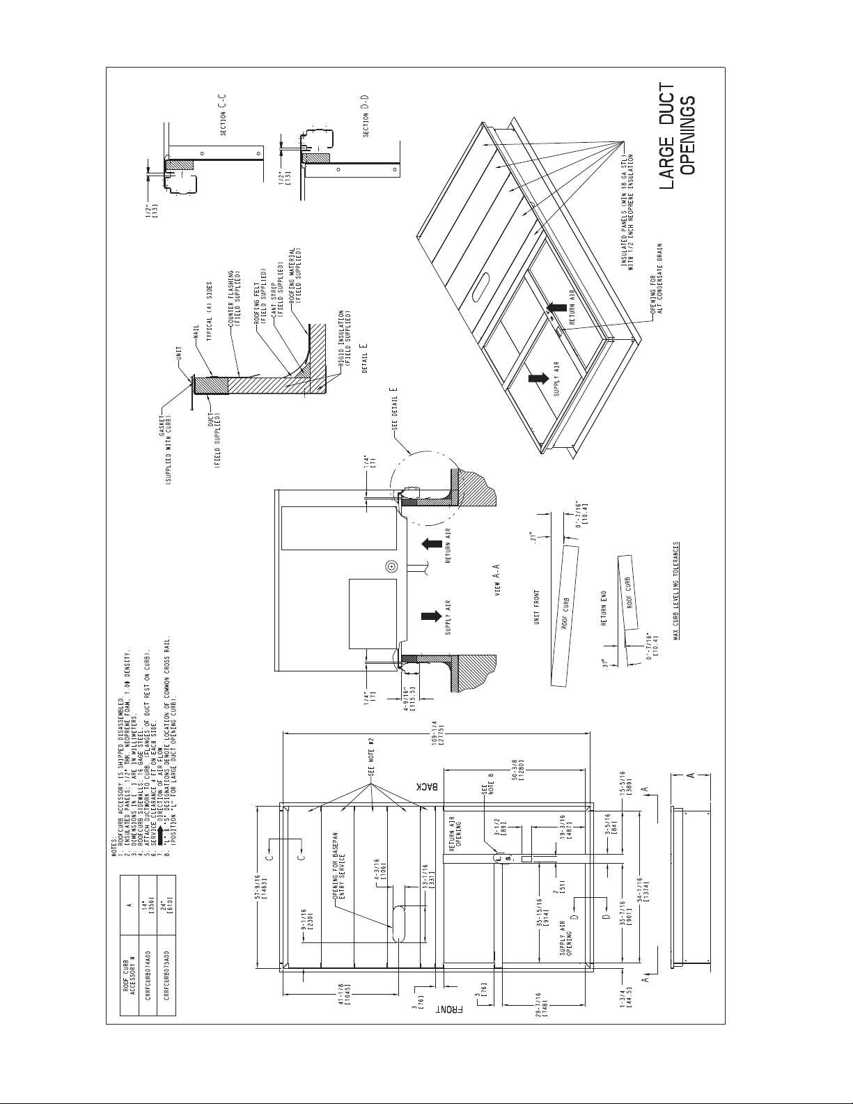
Fig. 4 — Roof Curb Details
8
Page 9
MAXIMUM ALLOWABLE DIFFERENCE IN. (MM)
A-B B-C A-C
0.5" (13) 1.0" (25) 1.0" (25)
A
B
C
Fig. 5 — Unit Leveling Tolerances
Install insulation, cant strips, roofing felt, and counter flashing as shown. Ductwork must be attached to curb and not to
the unit.
IMPORTANT: If the unit’s electric and control wiring is to
be routed through the basepan and the unit is equipped with
the factory-installed Thru-the-Base service option see the
following sections:
• Factory-Option Thru-Base Connections on page 19
If using the field-installed Thru-the-Base accessory follow
the instructions provided with the accessory kit.
NOTE: If electrical connection is not going to occur at this
time, tape or otherwise cover the fittings so that moisture does
not get into the building or conduit in the interim.
SLAB MOUNT (HORIZONTAL UNITS ONLY) — Provide a level concrete slab that extends a minimum of 6 in. (150
mm) beyond unit cabinet. Install a gravel apron in front of condenser coil air inlet to prevent grass and foliage from obstructing airflow.
NOTE: Horizontal units may be installed on a roof curb if
required.
ALTERNATE UNIT SUPPORT (IN LIEU OF CURB OR
SLAB MOUNT) — A non-combustible sleeper rail can be
used in the unit curb support area. If sleeper rails cannot be
used, support the long sides of the unit with a minimum of 3
equally spaced 4-in. x 4-in. (102 mm x 102 mm) pads on each
side.
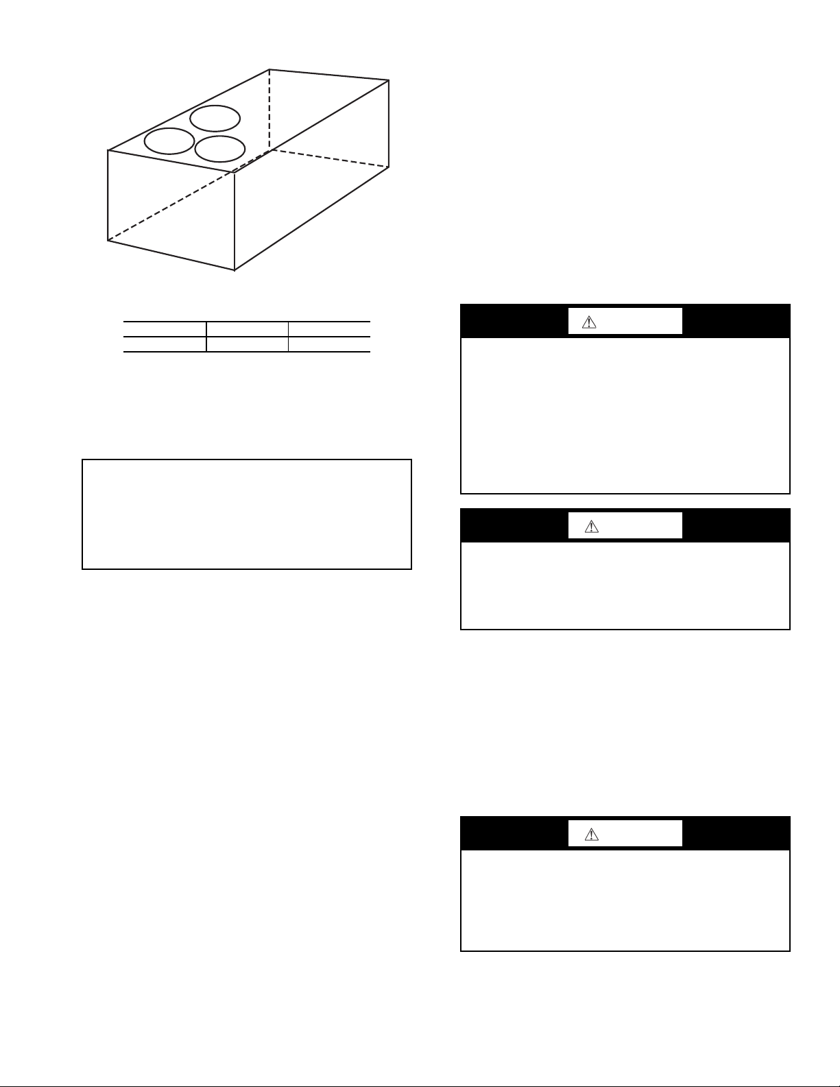
Step 5 — Field Fabricate Ductwork
NOTE: Cabinet return-air static pressure (a negative condition)
shall not exceed 0.35 in. wg (87 Pa) with economizer or 0.45
in. wg (112 Pa) without economizer.
For vertical ducted applications, secure all ducts to roof curb
and building structure. Do not connect ductwork to unit.
Fabricate supply ductwork so that the cross sectional dimensions are equal to or greater than the unit supply duct opening dimensions for the first 18 in. (458 mm) of duct length
from the unit basepan.
Insulate and weatherproof all external ductwork, joints, and
roof openings with counter flashing and mastic in accordance
with applicable codes.
Ducts passing through unconditioned spaces must be insulated and covered with a vapor barrier.
If a plenum return is used on a vertical unit, the return
should be ducted through the roof deck to comply with applicable fire codes.
FOR UNITS WITH ACCESSORY OR OPTIONAL ELECTRIC HEATERS — All installations require a minimum
clearance to combustible surfaces of 1-in. (25 mm) from duct
for first 12-in. (305 mm) away from unit.
Outlet grilles must not lie directly below unit discharge.
NOTE: A 90-degree elbow must be provided in the ductwork
to comply with UL (Underwriters Laboratories) code for use
with electric heat.
WARNING
PERSONAL INJURY HAZARD
Failure to follow this warning could cause personal injury.
For vertical supply and return units, tools or parts could
drop into ductwork and cause an injury. Install a 90-degree
turn in the return ductwork between the unit and the conditioned space. If a 90-degree elbow cannot be installed, then
a grille of sufficient strength and density should be installed
to prevent objects from falling into the conditioned space.
Due to electric heater, supply duct will require 90-degree
elbow.
CAUTION
PROPERTY DAMAGE HAZARD
Failure to follow this caution may result in damage to roofing materials.
Membrane roofs can be cut by sharp sheet metal edges. Be
careful when placing any sheet metal parts on such roof.
Step 6 — Rig and Place Unit — When the unit is
ready to be rigged and no longer will be lifted by a fork truck,
the wood protector under the basepan must be removed. Remove 4 screws from each base rail. Wood protector will drop to
the ground. See instructions on the unit base rails.
Keep unit upright and do not drop. Spreader bars are required. Rollers may be used to move unit across a roof. Level
by using unit frame as a reference. See Table 1 and Fig. 6 for
additional information.
Lifting holes are provided in base rails as shown in Fig. 6.
Refer to rigging instructions on unit.
CAUTION
UNIT DAMAGE HAZARD
Failure to follow this caution may result in equipment damage.
All panels must be in place when rigging. Unit is not
designed for handling by fork truck when panels or packaging are removed.
Before setting the unit onto the curb, recheck gasketing on
curb.
9
Page 10
NOTES:
1. SPREADER BARS REQUIRED — Top damage will occur if spreader bars are not
used.
2. Dimensions in ( ) are in millimeters.
3. Hook rigging shackles through holes in base rail, as shown in detail “A.” Holes in base
rails are centered around the unit center of gravity. Use wooden top to prevent rigging
straps from damaging unit.
UNIT
MAX
WEIGHT
DIMENSIONS
ABC
lb kg in. mm in. mm in. mm
50HC**14 2105 957 116.0 2945 62.5 1590 59.5 1510
DETAIL “A”
PLACE ALL SEAL STRIP IN PLACE BEFORE PLACING
UNIT ON ROOF CURB.
DUCT END
SEE DETAIL “A”
(914 - 1371)
36" - 54"
“B”
“A”
“C”
Fig. 6 — Rigging Details
POSITIONING ON CURB — For full perimeter curbs
CRRFCURB074A00 and 075A00, the clearance between the
roof curb and the front and rear base rails should be
(6.4 mm). The clearance between the curb and the end base
rails should be
1
/2 in. (13 mm). For retrofit applications with
1
/4 in.
curbs CRRFCURB003A01 and 4A01, the unit should be positioned as shown in Fig. 7. Maintain the 15.5 in. (394 mm) and
5
8
/8 in. (220 mm) clearances and allow the 225/16 in. (567 mm)
dimension to float if necessary.
Fig. 7 — Retrofit Installation Dimensions
If the alternative condensate drain location through the bottom of the unit is used in conjunction with a retrofit curb, the
hole in the curb must be moved 12.5 in. (320 mm) towards the
end of the unit. (See Fig. 8.)
Although unit is weatherproof, guard against water from
higher level runoff and overhangs.
Original
Position
Fig. 8 — Alternative Condensate Drain Hole
Positions
IMPORTANT: If the unit has the factory-installed Thruthe-Base option, make sure to complete installation of the
option before placing the unit on the roof curb. See the following section:
• Factory-Option Thru-Base Connections on page 19
NOTE: If electrical connections are not going to occur at this
time, tape or otherwise cover the fittings so that moisture does
not get into the building or conduit in the interim.
Remove all shipping materials and top skid. Remove extra
center post from the condenser end of the unit so that the condenser end of the unit matches Fig. 18-20. Recycle or dispose
of all shipping materials.
10
New Position
(moved 12.5 in.)
Page 11
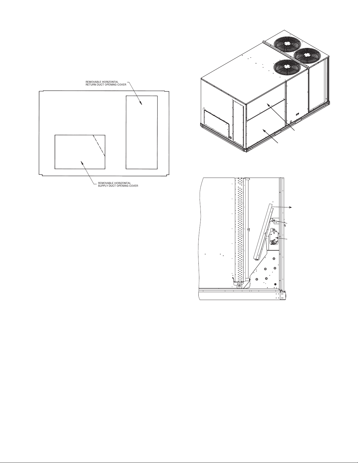
Step 7 — Convert to Horizontal and Connect
FILTER ACCESS PANEL
INDOOR COIL ACCESS PANEL
Ductwork (When Required) —
vertical duct configuration. Unit without factory-installed
economizer or return air smoke detector option may be fieldconverted to horizontal ducted configuration using accessory
CRDUCTCV002A00. To convert to horizontal configuration,
remove screws from side duct opening covers and remove covers. See Fig. 9.
Unit is shipped in the
Fig. 10 — Typical Access Panel Locations
Fig. 9 — Horizontal Conversion Panels
Discard the supply duct cover. Install accessory
CRDUCTCV002A00 to cover the vertical supply duct opening. Use the return duct cover removed from the end panel to
cover the vertical return duct opening.
Field-supplied flanges should be attached to horizontal duct
openings and all ductwork should be secured to the flanges. Insulate and weatherproof all external ductwork, joints, and roof
or building openings with counter flashing and mastic in accordance with applicable codes.
Do not cover or obscure visibility to the unit’s informative
data plate when insulating horizontal ductwork.
Step 8 — Install Outside Air Hood
ECONOMIZER HOOD REMOVAL AND SETUP — FACTORY OPTION
1. The hood is shipped in knock-down form and located in
the return air compartment. It is attached to the economizer using two plastic tie-wraps.
2. To gain access to the hood, remove the filter access panel.
(See Fig. 10.)
3. Locate and cut the (2) plastic tie-wraps, being careful to
not damage any wiring. (See Fig. 11.)
4. Carefully lift the hood assembly through the filter access
opening and assemble per the steps outlined in Economizer Hood and Two-Position Hood on page 12.
Remove Hood Parts
Cut Plastic Ties
(2) Places
Economizer
Fig. 11 — Economizer Hood Package Location
TWO POSITION DAMPER HOOD REMOVAL AND SETUP — FACTORY OPTION
1. The hood is shipped in knock-down form and assembled
to a metal support tray using plastic stretch wrap. Located
in the return air compartment, the assembly’s metal tray is
attached to the basepan and also attached to the damper
using two plastic tie-wraps.
2. To gain access to the hood, remove the filter access panel.
(See Fig. 10.)
3. Locate the (2) screws holding the metal tray to the basepan and remove. In order to remove the screws, it may be
necessary to remove the panel underneath the two-position damper. Remove the two screws. Locate and cut the
(2) plastic tie-wraps securing the assembly to the damper.
(See Fig. 12.) Be careful to not damage any wiring or cut
tie-wraps securing any wiring.
4. Carefully lift the hood assembly (with metal tray) through
the filter access opening and assemble per the steps outlined in Economizer Hood and Two-Position Hood on
page 12.
11
Page 12
5. If removed, reattach the panel under the damper.
Hood Parts
Plastic Tie Wrap
Qty (2)
Screws for Metal Tray
Qty (2)
TOP
PAN EL
INDOOR COIL
ACCESS PANEL
SCREW
HOOD DIVIDER
LEFT
HOOD
SIDE
Fig. 12 — Two-Position Damper Hood Package
Location
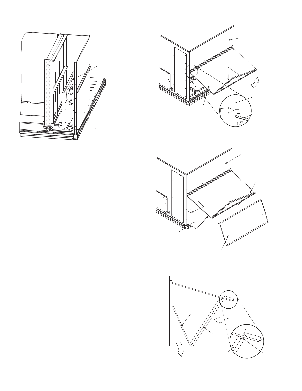
ECONOMIZER HOOD AND TWO-POSITION HOOD
NOTE: If the power exhaust accessory is to be installed on the
unit, the hood shipped with the unit will not be used and must
be discarded. Save the aluminum filter for use in the power
exhaust hood assembly.
1. The indoor coil access panel will be used as the top of the
hood. If the panel is still attached to the unit, remove the
screws along the sides and bottom of the panel. See
Fig. 13.
2. Swing out indoor coil access panel and insert the hood
sides under the panel (hood top). Be careful not to lift the
panel too far as it might fall out. Use the screws provided
to attach the hood sides to the hood top. Use screws provided to attach the hood sides to the unit. See Fig. 14.
3. Remove the shipping tape holding the economizer barometric relief damper in place.
4. Insert the hood divider between the hood sides. See
Fig. 14 and 15. Secure hood divider with 3 screws on
each hood side. The hood divider is also used as the bottom filter rack for the aluminum filter.
5. Attach the post that separates the filters with the screws
provided.
6. Open the filter clips which are located underneath the
hood top. Insert the aluminum filters into the bottom filter
rack (hood divider). Push the filter into position past the
open filter clips. Close the filter clips to lock the filters
into place. See Fig. 15.
7. Install the two rain deflectors on the edge of the hood top
as shown in Fig. 13.
8. Caulk the ends of the joint between the unit top panel and
the hood top as shown in Fig. 13.
9. Replace the filter access panel.
12
SIDE
PAN EL
RAIN DEFLECTORS
TOP
PAN EL
INDOOR
COIL
ACCESS
PAN EL
INDOOR
COIL
ACCESS
PAN EL
CAULK
HERE
Fig. 13 — Indoor Coil Access Panel Relocation
Fig. 14 — Economizer Hood Construction
DIVIDER
OUTSIDE
AIR
HOOD
CLEANABLE
ALUMINUM
FILTER
BAROMETRIC
RELIEF
FILTER
Fig. 15 — Economizer Filter Installation
FILTER
CLIP
Page 13
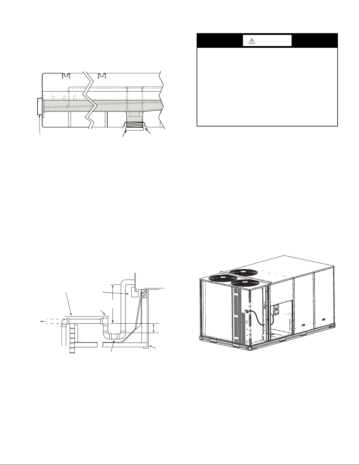
Step 9 — Install External Condensate Trap
DRAIN
(FACTORY-INSTALLED)
PLUG
CONDENSATE PAN (SIDE VIEW)
STANDARD
SIDE DRAIN
ALTERNATE
BOTTOM DRAIN
NOTE: Trap should be deep enough to offset maximum unit static
difference. A 4 in. (102 mm) trap is recommended.
MINIMUM PITCH
1˝ (25 mm) PER
10´ (3 m) OF LINE
BASE RAIL
OPEN
VENT
TO ROOF
DRAIN
DRAIN PLUG
ROOF
CURB
SEE NOTE
3˝(76 mm)
MIN
and Line —
nection on the end of the condensate pan and an alternate connection on the bottom. See Fig. 16. Unit airflow configuration
does not determine which drain connection to use. Either drain
connection can be used with vertical or horizontal applications.
Fig. 16 — Condensate Drain Pan (Side View)
When using the standard side drain connection, ensure the
red plug in the alternate bottom connection is tight. Do this before setting the unit in place. The red drain pan can be tightened
1
with a
/2-in. square socket drive extension.
To use the alternate bottom drain connection, remove the
red drain plug from the bottom connection (use a
socket drive extension) and install it in the side drain connection.
The piping for the condensate drain and external trap can be
completed after the unit is in place. See Fig. 17.
All units must have an external trap for condensate drainage. Install a trap at least 4-in. (102 mm) deep and protect
against freeze-up. If drain line is installed downstream from the
external trap, pitch the line away from the unit at 1-in. per 10 ft
(25 mm in 3 m) of run. Do not use a pipe size smaller than the
unit connection (
The unit has one 3/4-in. condensate drain con-
1
/2-in. square
3
/4-in.).
Step 10 — Make Electrical Connections
WARNING
ELECTRICAL SHOCK HAZARD
Failure to follow this warning could result in personal
injury or death.
Unit cabinet must have an uninterrupted, unbroken electrical ground to minimize the possibility of personal injury if
an electrical fault should occur. This ground may consist of
electrical wire connected to unit ground lug in control compartment, or conduit approved for electrical ground when
installed in accordance with NEC (National Electrical
Code); ANSI/NFPA 70, latest edition (in Canada, Canadian Electrical Code CSA [Canadian Standards Association] C22.1), and local electrical codes.
NOTE: Field-supplied wiring shall conform with the limitations of minimum 63°F (3°C) rise.
FIELD POWER SUPPLY — For those units without
through-the-curb power, conduit must be used to route the
main power from the condenser end, via the power entry in the
corner post of the unit (see Fig. 18-20) to either the factory option disconnect or the bottom of the control box. 1-in. conduit
is provided wrapped around compressor. A second conduit is
provided with factory installed powered convenience outlet.
For those units that require conduit larger than 1-in., it must be
field supplied. Figures 18-20 show the wire routings.
If the field disconnect is larger than 100A, it must be attached to the unit using accessory CRDISBKT001A00 — disconnect switch bracket (see Fig. 21). Follow the instructions
provided with this accessory. For smaller field disconnects, be
sure to use
end panel (see Fig. 22). In either case, set the disconnect vertical location on the unit so that a 90 degree fitting can be used to
connect the conduit to the disconnect.
1
/2-in. screws to mount the disconnect directly to the
Fig. 17 — Condensate Drain Piping Details
Fig. 18 — Conduit into Factory Option Non-Fused
Disconnect or HACR
13
Page 14
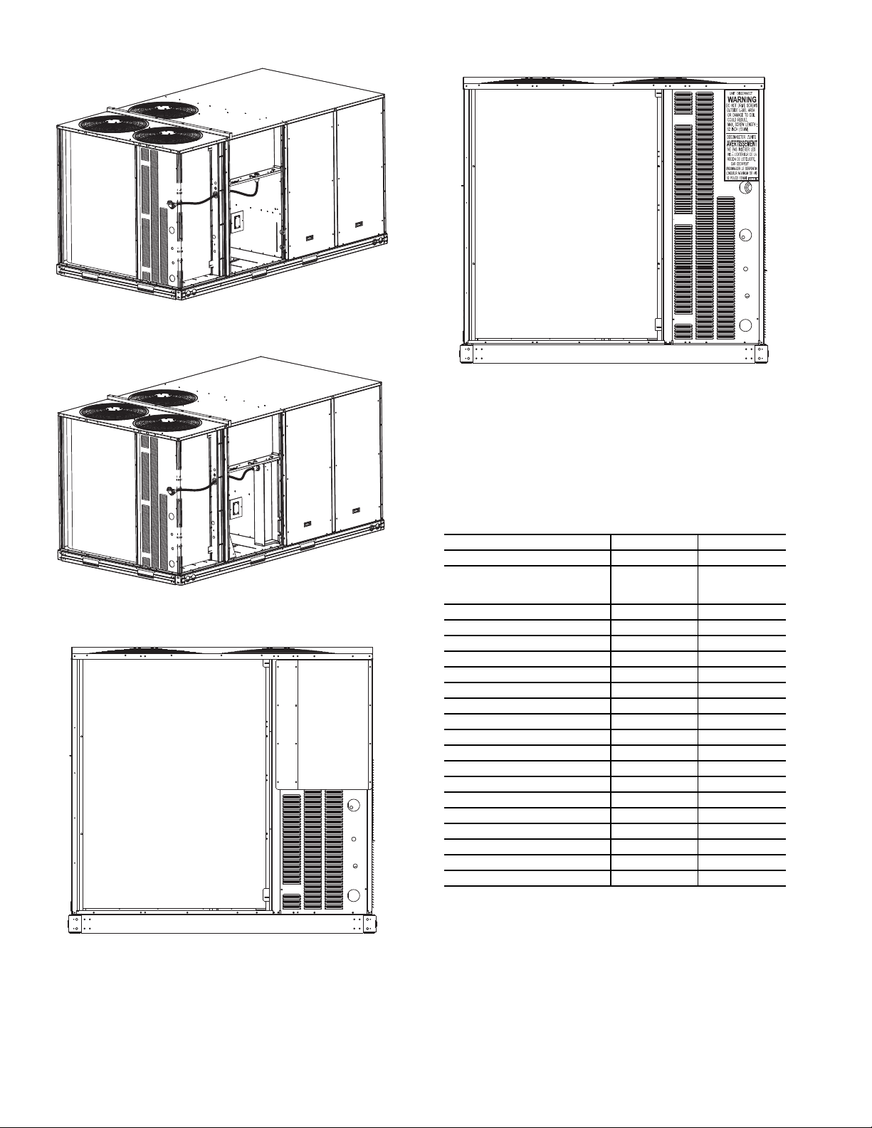
Fig. 19 — Conduit into Control Box
Fig. 22 — Mounting Position for Field Disconnects
(up to 100A)
Field power wires are connected to the unit at line-side pressure lugs at the main terminal block (TB1) or at factoryinstalled option non-fused disconnect switch or HACR, or field
or factory-installed Single Point box for electric heat. Refer to
Table 2 for maximum wire size at connection lugs. Use copper
wire only. See Fig. 23.
Table 2 — Connection Lug Min/Max Wire Sizes
Fig. 20 — Conduit into Single Point Box
Fig. 21 — Mounting Position for Field Disconnects
(over 100A)
MINIMUM MAXIMUM
TB1 in unit control box #14 #1
Terminal/Fuse block in
Single Point Box for Electric
Heat
80A Disconnect Option #14 #4
100A Disconnect Option #8 1/0
200A Disconnect Option #4 300 kcmil
25A HACR Option #14 1/0
30A HACR Option #14 1/0
35A HACR Option #14 1/0
40A HACR Option #14 1/0
50A HACR Option #14 1/0
60A HACR Option #14 1/0
70A HACR Option #14 1/0
80A HACR Option #14 1/0
90A HACR Option #14 1/0
100A HACR Option #14 1/0
110A HACR Option #4 300 kcmil
125A HACR Option #4 300 kcmil
150A HACR Option #4 300 kcmil
175A HACR Option #4 300 kcmil
200A HACR Option #4 300 kcmil
#8 3/0
NOTE: TEST LEADS — Unit may be equipped with short
leads (pigtails) on the field line connection points off the optional non-fused disconnect switch or HACR. These leads
are for factory run-test purposes only; remove and discard
before connecting field power wires to unit connection
points. Make field power connections directly to line connection pressure lugs only.
14
Page 15
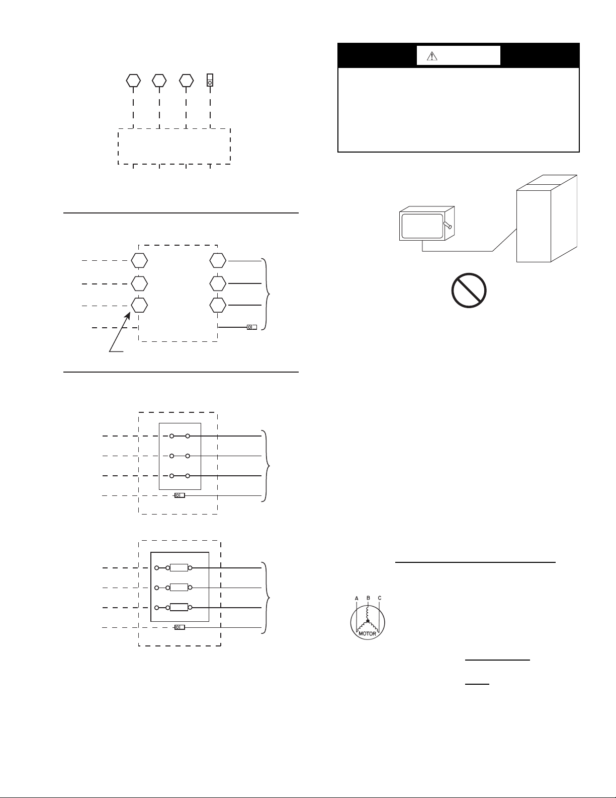
Units Without Single Point Box, Disconnect or HACR Option
Units With Disconnect or HACR Option
L1
L2
L3
2
4
6
1
5
Optional
Disconnect
Switch
or HACR
Disconnect factory test leads; discard.
Factory
Wiring
3
Equip GR Lug
Ground
(GR)
Units With Electric Heat Option with Single Point Box
and Without Disconnect or HACR Option
L1
L2
L3
Single Point Box
Factory
Wiring
Equip GR
Lug
Ground (GR)
Terminal Block
— OR —
L1
L2
L3
Single Point Box
Factory
Wiring
Equip GR
Lug
Ground (GR)
Fuse/Terminal Block
Fuse
Fuse
Fuse
Disconnect
per
NEC
11 1 2 13
L1 L2 L3
TB1
208/230-3-60
460-3-60
575-3-60
Ground
(GR)
Equip
GR Lug
WARNING
FIRE HAZARD
Failure to follow this warning could result in personal
injury, death, or property damage intermittent operation or
performance satisfaction.
Do not connect aluminum wire between disconnect switch
and air conditioning unit. Use only copper wire. (See
Fig. 24.)
ELECTRIC
DISCONNECT
SWITCH
COPPER
WIRE ONLY
ALUMINUM
WIRE
Fig. 24 — Disconnect Switch and Unit
ALL UNITS — All field wiring must comply with NEC and
all local requirements.
Size wire based on MCA (Minimum Circuit Amps) on the
unit informative plate. See Fig. 23 and the unit label diagram
for power wiring connections to the unit power terminal blocks
and equipment ground. Refer to Table 2 for maximum wire
size at connection lugs.
Provide a ground-fault and short-circuit over-current protection device (fuse or breaker) per NEC Article 440 (or local
codes). Refer to unit informative data plate for MOCP (Maximum Over-current Protection) device size.
NOTE: Units ordered with factory installed HACR do not
need an additional ground-fault and short-circuit over-current
protection device unless local codes require.
Voltage to compressor terminals during operation must be
within voltage range indicated on unit nameplate. On 3-phase
units, voltages between phases must be balanced within 2%
and the current within 10%. Use the following formula to determine the percent of voltage imbalance.
% Voltage imbalance
= 100 x
Example: Supply voltage is 230-3-60.
max voltage deviation from average voltage
average voltage
AB = 224 v
BC = 231 v
AC = 226 v
Fig. 23 — Power Wiring Connections
Average Voltage =
Determine maximum deviation from average voltage.
(AB) 227
(BC) 231
(AC) 227
– 224 = 3 v
– 227 = 4 v
– 226 = 1 v
Maximum deviation is 4 v.
224 + 231 + 226
681
=
3
=
227
3
15
Page 16
Determine percent of voltage imbalance.
4
226
% Voltage Imbalance = 100 x
= 1.76%
This amount of phase imbalance is satisfactory as it is below the
maximum allowable 2%.
IMPORTANT: If the supply voltage phase imbalance is more
than 2%, contact your local electric utility company immediately.
All units except 208/230-v units are factory wired for the
voltage shown on the nameplate. If the 208/230-v unit is to be
connected to a 208-v power supply, the control transformer
must be rewired by moving the black wire with the
male spade connector from the 230-v connection and moving it
to the 200-v
1
/4-in. male terminal on the primary side of the
1
/4-in. fe-
transformer. Refer to unit label diagram for additional
information.
CAUTION
UNIT DAMAGE HAZARD
Failure to follow this caution may result in equipment
damage.
Operation on improper line voltage or excessive phase
imbalance constitutes abuse and may cause damage to
electrical components. Such operation would invalidate
any applicable Carrier warranty.
NOTE: Check all factory and field electrical connections for
tightness.
UNITS WITHOUT FACTORY-INSTALLED NON-FUSED
DISCONNECT OR HACR — When installing units, provide
a disconnect switch of adequate size per NEC (National Electrical Code). Disconnect sizing data is provided on the unit informative plate. Locate on unit cabinet or within sight of the
unit per national or local codes. Do not cover unit informative
plate if mounting the disconnect on the unit cabinet.
UNITS WITH FACTORY-INSTALLED NON-FUSED
DISCONNECT OR HACR — The factory-installed option
non-fused disconnect switch (NFD) is located in a weather-
proof enclosure located under the main control box. The manual switch handle is shipped in the disconnect or HACR enclosure. Assemble the shaft and handle to the switch or HACR at
this point. Discard the factory test leads (see Fig. 23). The factory disconnect is a 200A disconnect on 230-3-60 units and a
100A disconnect on 460-3-60 and 575-3-60 units. On units
with factory installed non-fused disconnect, without factory installed electric heat, the factory supplied load side wires may
be of insufficient size for accessory electric heat applications. If
so, remove the load side factory wiring. Re-size wires per unit
nameplate data provided with accessory electric heat.
Fig. 25 — Location of Non-Fused Disconnect
Enclosure
To field install the NFD shaft and handle:
1. Remove the unit front panel (see Fig. 2).
2. Remove (3) hex screws on the NFD enclosure - (2) on the
face of the cover and (1) on the bottom.
3. Remove the front cover of the NFD enclosure.
4. Make sure the NFD shipped from the factory is at OFF
position (the arrow on the black handle knob is at OFF).
5. Insert the shaft with the cross pin on the top of the shaft in
the horizontal position.
6. Measure the tip of the shaft to the top surface of the pointer to be 3.75 to 3.88 in. (95 to 99 mm) for 80A and 100A
NFD and 3.43 to 3.56 in. (87 to 90 mm) for 200A NFD.
7. Tighten the locking screw to secure the shaft to the NFD.
8. Turn the handle to the OFF position with red arrow pointing at OFF.
9. Install the handle on to the painted cover horizontally
with the red arrow pointing to the left.
10. Secure the handle to the painted cover with (2) screws
and lock washers supplied.
11. Engaging the shaft into the handle socket, re-install (3)
hex screws on the NFD enclosure.
12. Re-install the unit front panel.
16
Page 17
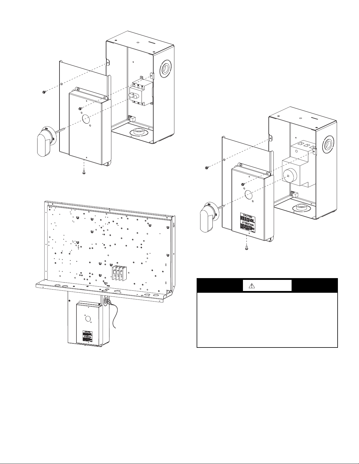
Fig. 26 — Handle and Shaft Assembly for NFD
6. Tighten the locking screw to secure the shaft to the
HACR.
7. Turn the handle to the OFF position with red arrow pointing at OFF.
8. Install the handle on to the painted cover horizontally
with the red arrow pointing to the left.
9. Secure the handle to the painted cover with (2) screws
and lock washers supplied.
10. Engaging the shaft into the handle socket, re-install (3)
hex screws on the HACR enclosure.
11. Re-install the unit front panel.
Fig. 27 — Location of HACR Enclosure
To field install the HACR shaft and handle:
1. Remove the unit front panel (see Fig. 2).
2. Remove (3) hex screws on the HACR enclosure - (2) on
the face of the cover and (1) on bottom.
3. Remove the front cover of the HACR enclosure.
4. Make sure the HACR shipped from the factory is at OFF
position (the white arrow pointing at OFF).
5. Insert the shaft all the way with the cross pin on the top of
the shaft in the horizontal position.
Fig. 28 — Handle and Shaft Assembly for HACR
CONVENIENCE OUTLETS
WARNING
ELECTRICAL OPERATION HAZARD
Failure to follow this warning could result in personal
injury or death.
Units with convenience outlet circuits may use multiple
disconnects. Check convenience outlet for power status
before opening unit for service. Locate its disconnect
switch, if appropriate, and open it. Lock-out and tag-out
this switch, if necessary.
Two types of convenience outlets are offered on the
50HC**14 models: non-powered and unit-powered. Both
types provide a 125-volt GFCI (ground-fault circuit-interrupter) duplex receptacle rated at 15-A behind a hinged waterproof
access cover, located on the panel beneath the control box. See
Fig. 29.
Non-powered type: This type requires the field installation
of a general-purpose 125-volt 15-A circuit powered from a
source elsewhere in the building. Observe national and local
codes when selecting wire size and conduit requirements, fuse
or breaker requirements and disconnect switch size and
location. Route 125-v power supply conductors into the bottom
of the utility box containing the duplex receptacle.
17
Page 18
UNIT
VOLTAGE
CONNECT ASPRIMARY
CONNECTIONS
TRANSFORMER
TERMINALS
208,230 240
L1: RED +YEL
L2: BLU + GRA
H1 + H3
H2 + H4
460 480
L1: RED
Splice BLU + YEL
L2: GRA
H1
H2 + H3
H4
575 600
L1: RED
L2: GRA
H1
H2
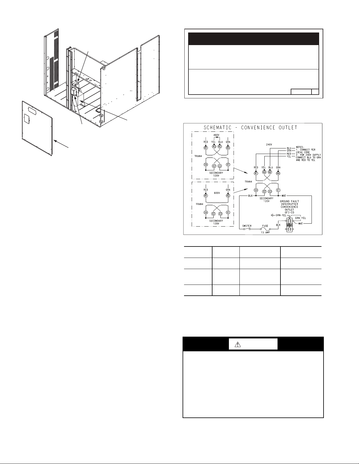
Pwd-CO
Fuse
Switch
Convenience
Outlet
GFCI
Disconnect
Access Panel
Fig. 29 — Convenience Outlet Location
Unit-powered type: A unit-mounted transformer is factory-installed to stepdown the main power suppl voltage to the
unit to 115-v at the duplex receptacle. This option also includes
a manual switch with fuse, located in a utility box and mounted
on a bracket behind the convenience outlet; access is through
the unit’s control box access panel. See Fig. 29.
The primary leads to the convenience outlet transformer are
not factory-connected. Selection of primary power source is a
customer-option. If local codes permit, the transformer primary
leads can be connected at the line-side terminals on the unitmounted non-fused disconnect; this will provide service power
to the unit when the unit disconnect switch is open. Other connection methods will result in the convenience outlet circuit being de-energized when the unit disconnect switch is open. See
Fig. 31. On a unit without a unit-mounted disconnect, connect
the source leads to the main terminal block (TB1).
If the convenience outlet transformer is connected to the
line side of a field disconnect, the conduit provided with the
unit must be used to protect the wire as they are routed from the
transformer to the field disconnect. The end of the conduit with
the straight connector attaches to the field disconnect. The other end does not need to connect to the transformer; however,
the conduit must be routed so that all wiring is either in the conduit or behind the access panel.
If the convenience outlet transformer is connected to the
line side of the factory disconnect option, route the wires
through the web bushing located on the bottom of the disconnect box. For the load side wiring to the factory option disconnect, route the wires through the hole on the right side of the
disconnect. Be sure to create a drip loop at least 6-in. long.
Test the GFCI receptacle by pressing the TEST button on
the face of the receptacle to trip and open the receptacle. Check
for proper grounding wires and power line phasing if the GFCI
receptacle does not trip as required. Press the RESET button to
clear the tripped condition.
Pwd-CO
Transformer
NOTICE/AVIS
Convenience Outlet Utilization
Maximum Intermittent Use 15 - Amps
Maximum Continuous Use 8 - Amps
Observe a 50% limit on the circuit
Loading above 8 - Amps
Utilisation de la prise utilitaire
Usage intermittent maximum 15 - Amps
Usage continu maximum 8 - Amps
Observez une limite de 50% sur le circuit
Chargement au-dessus de 8 - Amps
Fig. 30 — Convenience Utilization Notice
Fig. 31 — Unit Powered Convenience Outlet Wiring
Fuse on power type: The factory fuse is a Bussman “Fusetron” T-15, non-renewable screw-in (Edison base) type plug
fuse.
WARNING
ELECTRICAL OPERATION HAZARD
Failure to follow this warning could result in personal
injury or death.
Using unit-mounted convenience outlets: Units with unitmounted convenience outlet circuits will often require that
two disconnects be opened to de-energize all power to the
unit. Treat all units as electrically energized until the convenience outlet power is also checked and de-energization
is confirmed. Observe National Electrical Code Article
210, Branch Circuits, for use of convenience outlets.
Installing Weatherproof Cover: A weatherproof while-inuse cover for the factory-installed convenience outlets is now
required by UL standards. This cover cannot be factory-mount-
18
2.050HE501288
Page 19
ed due its depth; it must be installed at unit installation. For
shipment, the convenience outlet is covered with a blank cover
plate.
The weatherproof cover kit is shipped in the unit’s control
box. The kit includes the hinged cover, a backing plate and gasket.
DISCONNECT ALL POWER TO UNIT AND CONVENIENCE OUTLET. LOCK-OUT AND TAG-OUT ALL
POWER.
Remove the blank cover plate at the convenience outlet; discard the blank cover.
Loosen the two screws at the GFCI duplex outlet, until approximately
1
/2-in. (13 mm) under screw heads are exposed.
Press the gasket over the screw heads. Slip the backing plate
over the screw heads at the keyhole slots and align with the
gasket; tighten the two screws until snug (do not over-tighten).
Mount the weatherproof cover to the backing plate as
shown in Fig. 32. Remove two slot fillers in the bottom of the
cover to permit service tool cords to exit the cover. Check for
full closing and latching.
COVER – WHILE-IN-USE
WEATHERPROOF
RECEPTACLE
NOT SHOWN
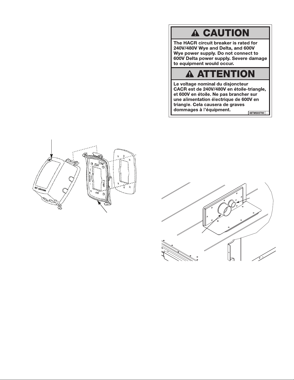
Fig. 33 — HACR Caution Label
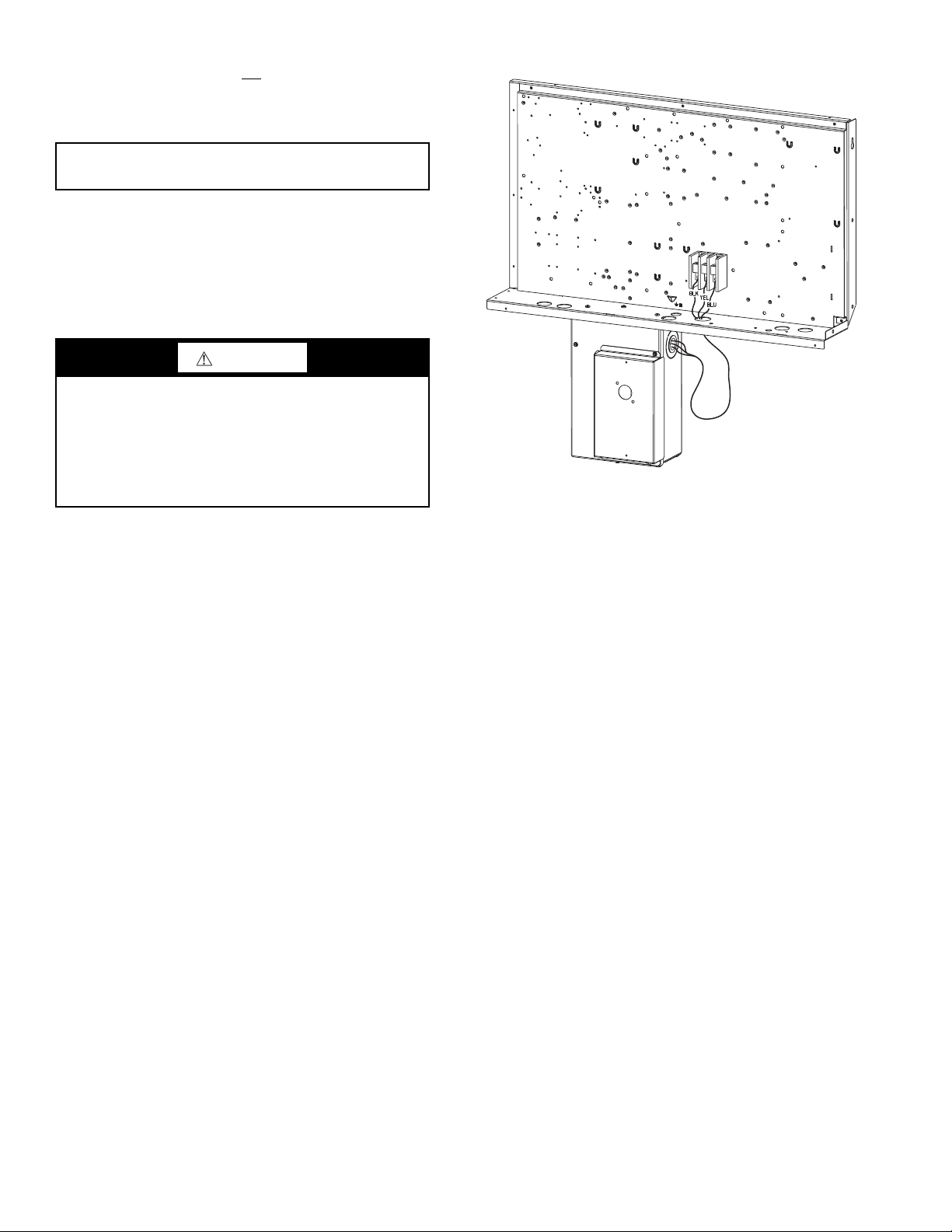
FACTORY OPTION THRU-BASE CONNECTIONS —
This service connection kit consists of a
head connector and a 1
1
/2-in. electrical bulkhead connector,
1
/2-in. electrical bulk-
connected to an “L” bracket covering the embossed (raised)
section of the unit basepan in the condenser section. See
Fig. 34. The
control wires to pass through the basepan. The 1
1
/2-in. bulkhead connector enables the low-voltage
1
/2-in. electrical bulkhead connector allows the high-voltage power wires to
pass through the basepan.
BASE PLATE FOR
GFCI RECEPTACLE
Fig. 32 — Weatherproof Cover Installation
HACR — The amp rating of the HACR factory-installed option is based on the size, voltage, indoor motor and other electrical options of the unit as shipped from the factory. If field-installed accessories are added or changed in the field (i.e., power
exhaust), the HACR may no longer be of the proper amp rating
and therefore will need to be removed from the unit. See unit
nameplate and label on factory-installed HACR for the amp
rating of the HACR that was shipped with the unit from the
factory. See unit nameplates for the proper fuse, HACR or
maximum over-current protection device required on the unit
with field-installed accessories.
1
/2” ELECTRICAL
BULKHEAD
CONNECTOR
11/2” ELECTRICAL
BULKHEAD
CONNECTOR
Fig. 34 — Thru-the Base Option, Shipping
Position
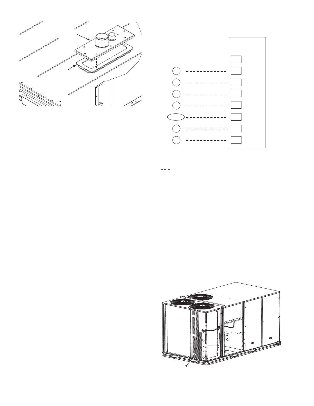
1. Remove the “L” bracket assembly from the unit.
2. Remove connector plate assembly from the “L” bracket
and discard the “L” bracket, but retain the washer head
screws and the gasket (located between the “L” bracket
and the connector plate assembly).
NOTE: Take care not to damage the gasket, as it is reused in
the following step.
3. Place the gasket over the embossed area in the basepan,
aligning the holes in the gasket to the holes in the basepan. See Fig. 35.
4. Install the connector plate assembly to the basepan using
8 of the washer head screws.
NOTE: If electrical connections are not going to occur at this
time, tape or otherwise cover the fittings so that moisture does
not get into the building or conduit in the interim.
19
Page 20
GASKET
CONNECTOR
PLATE
ASSEMBLY
NOTES:
1. Typical multi-function marking. Follow manufacturer’s configuration instructions to select Y2. Do not configure for O output.
2. W2 connection not required on units without electric heating.
Field Wiring
cannot be directly connected to the thermostat and will require
a junction box and splice at the thermostat.
Typical
Thermostat
Connections
Central
Terminal
Board
X
Fig. 35 — Installing Thru-the Base Option
Check tightness of connector lock nuts before connecting
electrical conduits.
Field-supplied and field-installed liquid-tight conduit connectors and conduit may be attached to the connectors on the
basepan. Pull correctly rated high voltage and low voltage
through appropriate conduits. Connect the power conduit to the
internal disconnect (if unit is so equipped) or to the external
disconnect (through unit side panel). Remove one of the two
knockouts located on the bottom left side of the unit control
box. Use this hole for the control conduit.
UNITS WITHOUT THRU-BASE CONNECTIONS
1. Install power wiring conduit through side panel openings.
Install conduit between disconnect and control box.
2. Install power lines to terminal connections as shown in
Fig. 23.
FIELD CONTROL WIRING — The 50HC**14 unit requires an external temperature control device. This device can
be a thermostat (field-supplied) or a PremierLink™ controller
(available as factory-installed option or as field-installed accessory, for use on a Carrier Comfort Network
®
or as a stand alone
control) or the RTU Open Controller for Building Management
Systems using non-CCN protocols (RTU Open controller is
available as a factory-installed option only).
THERMOSTAT — Select a Carrier-approved accessory
thermostat. When electric heat is installed in the 50HC unit, the
thermostat must be capable of energizing the G terminal (to energize the Indoor Fan Contactor) whenever there is a space call
for heat (energizing the W1 terminal). The accessory thermostats listed on the unit price pages can provide this signal but
they are not configured to enable this signal as shipped.
Install the accessory thermostat according to installation in-
structions included with the accessory.
Locate the thermostat accessory on a solid wall in the conditioned space to sense average temperature in accordance with
the thermostat installation instructions.
If the thermostat contains a logic circuit requiring 24-v power, use a thermostat cable or equivalent single leads of different
colors with minimum of seven leads. If the thermostat does not
require a 24-v source (no “C” connection required), use a thermostat cable or equivalent with minimum of six leads. Check
the thermostat installation instructions for additional features
which might require additional conductors in the cable.
For wire runs up to 50 ft (15 m), use no. 18 AWG (American Wire Gage) insulated wire (35°C minimum). For 50 to
75 ft (15 to 23 m), use no. 16 AWG insulated wire (35°C minimum). For over 75 ft (23 m), use no. 14 AWG insulated wire
(35°C minimum). All wire sizes larger than no. 18 AWG
C
G
W2
W1
O/B/Y2
(Note 1)
Y1
R
Note 1: Typical multi-function marking. Follow manufacturer’s configuration
instructions to select Y2. Do not configure for O output.
Note 2: W2 connection not required on units without electric heating.
Field Wiring
(Note 2)
C
G
W2
W1
Y2
Y1
R
T
H
E
R
M
O
S
T
A
T
Fig. 36 — Typical Low-Voltage Control
Connections
UNIT WITHOUT THRU-BASE CONNECTION KIT —
Pass the thermostat control wires through the bushing on the
unit end panel. Route the wire through the snap-in wire tie and
up to the web bushing near the control box. Route the wire
through the bushing and into the bottom left side of the control
box after removing one of the two knockouts in the corner of
the box. Using a connector at the control box to protect the
wire as it passes into the control box. Pull the wires over to the
terminal strip at the upper left corner of the Central Terminal
Board (CTB). Use the connector at the control box and the
wire tie to take up any slack in the thermostat wire to ensure
that it will not be damaged by contact with the condenser coil.
See Fig. 37.
NOTE: If thru-the-bottom connections accessory is used, refer
to the accessory installation instructions for information on
routing power and control wiring.
Fig. 37 — Thermostat Wire Routing
20
Page 21

HEATER
MOUNTING
BRACKET
HEATER
MODULE
(LOCATION 2)
HEATER
MODULE
(LOCATION 1)
SINGLE POINT
BOX
MOUNTING
SCREW
SINGLE
POINT BOX
HEATER
COVERS
MANUAL RESET
LIMIT SWITCH
DISCONNECT
MOUNTING
LOCATION
AL
LIED
P
A
M
O
DE
L
NO
.
ER
I
A
L
N
O.
C
O
R
P
.
O
D
2
2
.
2
3
1
2
3
ISTED
AIR
NDITIONING
UIP
ACCESS
346
N
.
P
/
N
2-
5
6
1
04
RE
V
1
1
13
2
1
2
3
CONTROL
BOX
BUSHING
SINGLE
POINT BOX
MOUNTING
SCREWS
FOAM
BUSHING
DRIP BOOT
BRACKET
MOUNTING
SCREWS
HEATER
RELAYS
POWER
WIRES
HEATER
MOUNTING
SCREWS
Fig. 38 — Typical Component Location
HEAT ANTICIPATOR SETTINGS — Set heat anticipator
settings at 0.14 amp for the first stage and 0.14 amp for secondstage heating, when available.
Electric Heaters — The 50HC-*14 units may be
equipped with factory or field-installed electric heaters. The
heaters are modular in design, with heater frames holding open
coil resistance wires strung through ceramic insulators, linebreak limit switches and a control contactor. One or two heater
modules may be used in a unit.
Heater modules are installed in the compartment below the
indoor (supply) fan outlet. Access is through the indoor access
panel. Heater modules slide into the compartment on tracks
along the bottom of the heater opening. See Fig. 38.
CAUTION
UNIT DAMAGE HAZARD
Failure to follow this caution may result in equipment
damage.
Not all available heater modules and single point boxes
may be used in every unit. Use only those heater modules
that are UL listed for use in a specific size unit. Refer to the
label on the unit cabinet for the list of approved heaters and
single point boxes.
Single Point Boxes — When heaters are installed,
power wiring to both heaters and the rest of the unit is connected via the single point box accessory, which will be installed
directly under the unit control box, just to the left of the partition separating the indoor section (with electric heaters) from
the outdoor section. The single point box has a hinged access
cover. See Fig. 39. The single point box also includes pigtails
to complete the wiring between the single point box and the
unit’s main control box terminals. The pigtails will already be
connected into the unit’s main control box on units with factory
installed electric heat. Refer to the accessory heater and Single
Point Box installation instructions for details on tap connections for field installed electric heat accessory.
Fig. 39 — Typical Single Point Installation
HEATER AND SUPPLEMENTARY FUSES — When the
unit MOCP device value exceeds 60-A, unit-mounted supplementary fuses are required for each heater circuit. These fuses
are included in accessory Single Point Boxes, with power distribution and fuse blocks.
All fuses on 50HC-*14 units are 60-A. (Note that all heaters
are qualified for use with a 60-A fuse, regardless of actual heater ampacity, so only 60-A fuses are necessary.)
HEATER LOW-VOLTAGE CONTROL CONNECTIONS — One or two heaters can be installed in the unit. Use
the wiring procedure listed below for each heater as determined
by the number of stages in the heater.
Single Stage Heaters: Single-stage heaters will have an orange and a brown control wire. Connect these to the orange and
brown wires located on TB4. See Fig. 40.
21
Page 22

NOTE:
Optional Outdoor Temperature Control
at One Heater Stage –
Move heater wire to this terminal and
connect outdoor temperature switch
between 2nd and 3rd terminals.
W2 UseW1 Use
VIO
12
CONTROL
BOARD
8
CONTROL
BOARD
R Use C Use
VIO
% RELATIVE HUMIDITY
®
Fig. 40 — Single Stage Heaters: TB4 Wiring
Connections
Two Stage Heaters: Two-stage heaters will have orange,
violet, red and brown wires. The orange and the purple are the
control wires and the red and brown wires feed the safety circuit. Connect both the orange and the purple wires to the orange wire locations of TB4. Connect the red and brown wires
to red and brown wires on TB4. If more than one heater is installed, repeat the wiring procedure for the second heater. The 3
locations across the top of TB4 do allow a switch to be installed in series with some of the heaters in order to add additional heater control. See Fig. 41.
NOTE: The low voltage wiring will already be completed on
units with factory installed electric heat.
4. Use the connector and the wire tie to reduce any slack in
the humidistat cable to ensure that it will not be damaged
by contact with the condenser coil (see Fig. 37).
5. Use wire nuts to connect humidistat cable to two PINK
leads in the low-voltage wiring as shown in Fig. 44).
To connect the Thermidistat device (33CS2PPRH-01):
1. Route the Thermidistat multi-conductor thermostat cable
(field-supplied) through the bushing in the unit’s louvered
end panel (see Fig. 37).
2. Route the cable through the snap-in wire tie and up to the
web bushing near the control box
3. Feed the cable through the bushing and into the bottom
left side of the control box after removing one of the two
knockouts in the corner of the box. Use a connector to
protect the cable as it enters the control box.
4. Use the connector and the wire tie to reduce any slack in
the thermostat cable to ensure that it will not be damaged
by contact with the condenser coil (see Fig. 37).
5. The Thermidistat has dry contacts at terminals D1 and D2
for dehumidification operation (see Fig. 45). The dry contacts must be wired between CTB terminal R and the
PINK lead to the LTLO switch with field-supplied wire
nuts. Refer to the installation instructions included with
the Carrier Edge Pro Thermidistat device for more information.
Fig. 41 — Two Stage Heaters: TB4 Wiring
Connections
Humidi-MiZer® System Control Connections
HUMIDI-MIZER — SPACE RH CONTROLLER
NOTE: The Humidi-MiZer system is a factory-installed
option.
The Humidi-MiZer dehumidification system requires a
field-supplied and installed space relative humidity control device. This device may be a separate humidistat control (contact
closes on rise in space RH above control setpoint) or a combination thermostat-humidistat control device such as Carrier’s
®
Pro Thermidistat with isolated contact set for dehumidi-
Edge
fication control. The humidistat is normally used in applications where a temperature control is already provided (units
with PremierLink™ control).
To connect the Carrier humidistat (HL38MG029):
1. Route the humidistat 2-conductor cable (field-supplied)
through the bushing in the unit’s louvered end panel (see
Fig. 37).
2. Route the cable through the snap-in wire tie and up to the
web bushing near the control box.
3. Feed the cable through the bushing and into the bottom
left side of the control box after removing one of the two
knockouts in the corner of the box. Use a connector to
protect the cable as it enters the control box.
Fig. 42 — Accessory Field-Installed Humidistat
Fig. 43 — Edge Pro Thermidistat
22
Page 23

Fig. 44 — Typical Humidi-MiZer
®
Adaptive Dehumidification System Humidistat Wiring
23
Page 24

Fig. 45 — Typical Rooftop Unit with Humidi-MiZer Adaptive Dehumidification System with
Rc
Rh
W1
G
Y2
C
O/W2/B
Y1
OAT
RR
S
S
RTN
HUM
D1
D2
V+
Vg
X
*
C
G
W2
W1
Y2
Y1
R
Edge Programable Thermostat
Unit CTB
THERMOSTAT
*Connection not required.
Humidi-MiZer™ FIOP
EconoMi$er® X (Factory-Installed Option)
PRODUCT DESCRIPTION — The EconoMi$er X system
is an expandable economizer control system, which includes a
W7220 economizer module (controller) with an LCD and keypad (See Fig. 46). The W7220 can be configured with optional
sensors.
Fig. 46 — W7220 Economizer Module
The W7220 economizer module can be used as a standalone economizer module wired directly to a commercial setback space thermostat and sensors to provide outside air drybulb economizer control.
The W7220 economizer module can be connected to optional sensors for single or differential enthalpy control. The
W7220 economizer module provides power and communications for the sensors.
The W7220 economizer module automatically detects
sensors by polling to determine which sensors are present. If a
®
Edge
Pro Thermidistat Device
24
sensor loses communications after it has been detected, the
W7220 economizer controller indicates a device fail error on
its LCD.
SYSTEM COMPONENTS — The EconoMi$er X system includes an economizer module, 20k mixed air sensor, damper
actuator, and either a 20k outdoor air temperature sensor or SBus enthalpy sensors.
Economizer Module
— The module is the core of the
EconoMi$er X system. The module is mounted in the unit’s
control box, and includes the user interface for the system. The
W7220 economizer module provides the basic inputs and outputs to provide simple economizer control. When used with the
optional sensors, the economizer module provides more advanced economizer functionality.
S-Bus Enthalpy Control Sensors
— The sensor is a combination temperature and humidity sensor which is powered by
and communicates on the S-Bus. Up to three sensors may be
configured with the W7220 economizer module.
CO
Sensor (optional) — The sensor can be added for De-
2
mand Controlled Ventilation (DCV).
SPECIFICATIONS
W7220 Economizer Module
— The module is designed for
use with 2 to 10 Vdc or bus communicating actuator. The module includes terminals for CO
sensor, Mixed Air sensor, and
2
an Outdoor Dry Bulb sensor. Enthalpy and other options are
available with bus sensors.
User Interface
— Provides status for normal operation, setup
parameters, checkout tests, and alarm and error conditions with
a 2-line 16 character LCD display and four button keypad.
Electrical
Rated Voltage — 20 to 30 Vac RMS, 50/60 Hz
Transformer — 100 va maximum system input
Nominal Power Consumption (at 24 Vac, 60 Hz) — 11.5
VA without sensors or actuators
Page 25

NA
AUX2-
OCC
E-GND
EXH1
AUX1-O
Y2-
Y1-
Y2-O
Y1-O
C
R
50048848-002
Rev. A
NA
A2
OCC
EX
A1
Y2I
Y2O
Y1I
Y1O
C
R
Cert Product
California Title 24, Part 6
HJW10
www.energy.ca.gov
MAT
MAT
OAT
OAT
S-BUS
S-BUS
IAQ 2-10
IAQ COM
IAQ 24V
ACT 2-10
ACT CO M
ACT 24V
MA
MA
OA
OA
SB
SB
SB
SB
SB
SB
V
C
R
V
C
R
NA
50040839-001
Rev. G
Relay Digital Output Rating at 30 Vac (maximum power
from Class 2 input only) — 1.5A run:
3.5A inrush at 0.45PF (200,000 cycles) or
7.5A inrush at 0.45PF (100,000 cycles)
External Sensors Power Output — 21 Vdc ± 5% at 48mA
IMPORTANT: All inputs and outputs must be Class 2
wiring.
INPUTS
Sensors
NOTE: A Mixed Air (MA) analog sensor is required on all
W7220 units; either an Outdoor Air (OA) sensor for dry bulb
change over or an OA bus sensor for outdoor enthalpy change
over is required in addition to the MA sensor. An additional
Return Air (RA) bus sensor can be added to the system for differential enthalpy or dry bulb changeover. For differential dry
bulb changeover a 20k ohm sensor is required in the OA and a
bus sensor in the RA. DIP switch on RA bus sensor must be
set in the RA position.
Dry Bulb Temperature (optional) and Mixed Air (required),
20k NTC
2-wire (18 to 22 AWG);
Temperature range -40 to 150 F (-40 to 65 C)
Temperature accuracy -0 F/+2 F
Temperature and Humidity, C7400S1000 (optional)
S-Bus; 2-wire (18 to 22 AWG)
Temperature: range -40 to 150 F (-40 to 65 C)
Temperature accuracy -0 F/+2 F
Humidity: range 0 to 100% RH with 5% accuracy.
NOTE: Up to three (3) S-Bus sensors may be connected to the
W7220 economizer module. For outdoor air (OA), return air
(RA) and discharge (supply) air (DA).
4 Binary Inputs — 1-wire 24 Vac + common GND (see page
27 for wiring details).
24 Vac power supply — 20 to 30 Vac 50/60Hz; 100 VA Class
2 transformer.
OUTPUTS
Actuator Signal:
2k ohm; bus two-wire output for bus communicating actuators.
Exhaust fan, Y1, Y2 and AUX1 O:
All Relay Outputs (at 30 Vac):
Running: 1.5A maximum
Inrush: 7.5A maximum
ENVIRONMENTAL
Operating Temperature:
-40 to 150 F (-40 to 65 C).
Exception of display operation down to -4 F with full
recovery at -4 F from exposure to -40 F
Storage Temperature
-40 to 150 F (-40 to 65 C)
Shipping Temperature:
-40 to 150 F (- 40 to 65 C)
Relative Humidity:
5% to 95% RH non-condensing
2-10 Vdc; minimum actuator impedance is
:
ECONOMIZER MODULE WIRING DETAILS — Use
Fig. 47 and Tables 3 and 4 to locate the wiring terminals for the
Economizer module.
NOTE: The four terminal blocks are removable. You can slide
out each terminal block, wire it, and then slide it back into
place.
Fig. 47 — W7220 Wiring Terminals
Table 3 — Economizer Module - Left Hand
Terminal Blocks
LABEL TYPE DESCRIPTION
Top Left Terminal Block
MAT
MAT
OAT
OAT
S-BUS
S-BUS
IAQ 2-10 2-10 vdc
IAQ COM COM Air Quality Sensor Common
IAQ 24V 24 vac Air Quality Sensor 24 vac Source
ACT 2-10 2-10 vdc Damper Actuator Output (2-10 vdc)
ACT COM COM Damper Actuator Output Common
ACT 24v 24 vac Damper Actuator 24 vac Source
20k NTC
and COM
20k NTC
and COM
S-BUS
(Sylk Bus)
Bottom Left Terminal Block
Mixed Air Temperature Sensor (Polarity
Insensitive Connection)
Outdoor Air Temperature Sensor
(Polarity Insensitive Connection)
Enthalpy Control Sensor
(Polarity Insensitive Connection)
Air Quality Sensor Input (e.g. CO
sensor)
2
25
Page 26

Table 4 — Economizer Module - Right Hand
DIP
Switch
Label
DIP
Switches
(3)
S-Bus
2 Pin Side
Connector
S-Bus
Terminals
(1 and 2)
Terminal Blocks
LABEL TYPE DESCRIPTION
Top Right Terminal Blocks
AUX2 I 24 vac IN The first terminal is not used.
Shut Down (SD) or HEAT (W)
OCC 24 vac IN
E-GND E-GND Occupied/Unoccupied Input
EXH1
AUX1 O
Y2-I 24 vac IN
Y2-O
Y1-I 24 vac IN
Y1-O
C COM 24 vac Common
R 24 vac 24 vac Power (hot)
24 vac
OUT
24 vac
OUT
Bottom Right Terminal Blocks
24 vac
OUT
24 vac
OUT
Conventional only
and
Heat Pump Changeover (O-B) in Heat
Pump mode.
Exhaust Fan 1 Output
Programmable:
Exhaust fan 2 output
or
ERV
or
System alarm output
Y2 in - Cooling Stage 2 Input from
space thermostat
Y2 out - Cooling Stage 2 Output to
stage 2 mechanical cooling
Y1 in - Cooling Stage 2 Input from
space thermostat
Y1 out - Cooling Stage 2 Output to
stage 2 mechanical cooling
S-BUS SENSOR WIRING — The labels on the sensors and
controller are color coded for ease of installation. Orange labeled sensors can only be wired to orange terminals on the controller. Brown labeled sensors can only be wired to S-bus
(brown) terminals. Use Fig. 48 and Table 5 to locate the wiring
terminals for each S-Bus sensor.
Use Fig. 48 and Table 5 to locate the wiring terminals for
each enthalpy control sensor.
Table 5 — HH57AC081 Sensor Wiring
Terminations
TERMINAL
NUMBER LABEL
1 S-BUS S-BUS
2 S-BUS S-BUS
TYPE DESCRIPTION
S-BUS
Communications
(Enthalpy Control
Sensor Bus)
S-BUS
Communications
(Enthalpy Control
Sensor Bus)
Use Fig. 48 and Table 6 to set the DIP switches for the
desired use of the sensor.
Table 6 — HH57AC081 Sensor DIP Switch
DIP SWITCH POSITIONS FOR SWITCHES 1, 2, AND 3
USE
DA OFF ON OFF
RA ON OFF OFF
OA OFF OFF OFF
123
NOTE: When a S-Bus sensor is connected to an existing network, it will take 60 minutes for the network to recognize and
auto-configure itself to use the new sensor.
During the 60 minute setup period, no alarms for sensor
failures (except SAT) will be issued and no economizing function will be available.
SENSOR WIRING — When using a CO2 sensor the
CO
2
black and brown common wires are internally connected and
only one is connected to “IAQ COM” on the W7220. Use the
power from the W7220 to power the CO
sensor OR make sure
2
the ground for the power supplies are common. See Fig. 49 for
CO
sensor wiring.
2
CO2 SENSOR
L1
(HOT)
L2
1
24V
ANALOG
OUT
+
–
RED
BLACK
YELLOW
BROWN
ORANGE
GREEN
Fig. 48 — S-Bus Sensor DIP Switches
1
POWER SUPPLY. PROVIDE DISCONNECT
MEANS AND OVERLOAD PROTECTION
AS REQUIRED.
Fig. 49 — CO
Sensor Wiring
2
INTERFACE OVERVIEW — This section describes how to
use the Economizer’s user interface for:
• Keypad and menu navigation
• Settings and parameter changes
• Menu structure and selection
USER INTERFACE — The user interface consists of a 2-line
LCD display and a 4-button keypad on the front of the economizer controller.
KEYPAD — The four navigation buttons (see Fig. 50) are
used to scroll through the menus and menu items, select menu
items, and to change parameter and configuration settings.
To use the keypad when working with menus:
• Press the ▲ (Up arrow) button to move to the previous
menu.
• Press the ▼ (Down arrow) button to move to the next
menu.
26
Page 27

• Press the (Enter) button to display the first item in the
currently displayed menu.
Fig. 50 — W7220 Controller Navigation Buttons
Press the (Menu Up/Exit) button to exit a menu’s
item and return to the list of menus. To use the keypad when
working with Setpoints, System and Advanced Settings,
Checkout tests and Alarms:
1. Navigate to the desired menu.
2. Press the (Enter) button to display the first item in the currently displayed menu.
3. Use the ▲ and ▼ buttons to scroll to the desired parameter.
4. Press the (Enter) button to display the value of the currently displayed item.
5. Press the ▲ button to increase (change) the displayed parameter value.
6. Press the ▼ button to decrease (change) the displayed parameter value.
NOTE: When values are displayed, pressing and holding the
or button causes the display to automatically increment.
7. Press the (Enter) button to accept the displayed value and
store it in nonvolatile RAM.
8. “CHANGE STORED” displays.
9. Press the (Enter) button to return to the current menu parameter.
10. Press the (Menu Up/Exit) button to return to the previous
menu.
MENU STRUCTURE — Table 7 illustrates the complete hierarchy of menus and parameters for the EconoMi$er
®
X sys-
tem.
The Menus in display order are:
• STATUS
•SETPOINTS
• SYSTEM SETUP
• ADVANCED SETUP
• CHECKOUT
•ALARMS
IMPORTANT: Table 7 illustrates the complete hierarchy. Your menu parameters may be different depending
on your configuration.
For example if you do not have a DCV (CO
) sensor,
2
then none of the DCV parameters appear and only MIN
POS will display. If you have a CO
sensor, the DCV MIN
2
and DCV MAX will appear AND if you have 2 speed fan
DCV MIN (high and low speed) and DCV MAX (high
and low speed will appear).
NOTE: Some parameters in the menus use the letters MA or
MAT, indicating a mixed air temperature sensor location
before the cooling coil. This unit application has the control
sensor located after the cooling coil, in the fan section, where it
is designated as (Cooling) Supply Air Temperature or SAT
sensor.
SETUP AND CONFIGURATION — Before being placed
into service, the W7220 Economizer module must be setup and
configured for the installed system.
IMPORTANT: During setup, the economizer module is
live at all times.
The setup process uses a hierarchical menu structure that is
easy to use. Press the ▲ and ▼ arrow buttons to move forward
and backward through the menus and press the button to select
and confirm setup item changes.
TIME-OUT AND SCREENSAVER — When no buttons
have been pressed for 10 minutes, the LCD displays a screen
saver, which cycles through the Status items. Each Status items
displays in turn and cycles to the next item after 5 seconds.
27
Page 28

MENU PARAMETER
ECONO AVAIL NO YES/NO
ECONOMIZING NO YES/NO
OCCUPIED NO YES/NO
HEAT PUMP N/A
COOL Y1—IN OFF ON/OFF
COOL Y1—OUT OFF ON/OFF
COOL Y2—IN OFF ON/OFF
COOL Y2—OUT OFF ON/OFF
MA TEMP _ _ . _ F 0 to 140 F
STATUS
DA TEMP _ _ . _ F 0 to 140 F
OA TEMP _ _ . _ F -40 to 140 F
OA HUM _ _ % 0 to 100%
RA TEMP _ _ . _ F 0 to 140 F
RA HUM _ _ % 0 to 100%
IN CO2 _ _ _ ppm 0 TO 2000 ppm
DCV STATUS N/A ON/OFF
DAMPER OUT 2.0v 2.0 TO 10.0v Displays voltage output to the damper actuator.
ACT POS N/A 0 to 100% Displays actual position of outdoor air damper actuator
Table 7 — Menu Structure
PARAMETER
DEFAULT
VALUE
PARAMETER
RANGE AND
INCREMENT
COOL
HEAT
NOTES
FIRST STAGE COOLING DEMAND (Y1–IN)
YES = economizing available; the system can use outside air for free
cooling when required
FIRST STAGE COOLING RELAY OUTPUT
YES = outside air being used for 1 stage cooling
OCCUPIED
YES = OCC signal received from space thermostat or
unitary controller
YES = 24 Vac on terminal OCC
NO = 0 Vac on terminal OCC
HEAT PUMP MODE
Displays COOL or HEAT when system is set to heat pump
(Non-conventional)
FIRST STAGE COOLING DEMAND (Y1-IN)
Y1–I signal from space thermostat or unitary controller for cooling stage
1.
ON = 24 Vac on terminal Y1–I
OFF = 0 Vac on terminal Y1–I
FIRST STAGE COOLING RELAY OUTPUT
Cool stage 1 Relay Output to stage 1 mechanical cooling
(Y1–OUT terminal)
SECOND STAGE COOLING DEMAND (Y2–IN)
Y2–I signal from space thermostat our unitary controller for second
stage cooling.
ON = 24 Vac on terminal Y2–I
OFF = 0 Vac on terminal Y2–I
SECOND STAGE COOLING RELAY OUTPUT
Cool Stage 2 Relay Output to mechanical cooling
(Y2–OUT terminal)
SUPPLY AIR TEMPERATURE, Cooling Mode
Displays value of measured mixed air from MAT sensor.
Displays _ _ . _ F if not connected, short or out-of-range.
DISCHARGE AIR TEMPERATURE, after Heating section
Displays when Discharge Air sensor is connected and displays measured discharge temperature.
Displays _ _ . _F if sensor sends invalid value, if not connected, short or
out-of-range.
OUTSIDE AIR TEMP
Displays measured value of outdoor air temperature.
Displays _ _ . _F if sensor sends invalid value, short or
out-of-range.
OUTSIDE AIR RELATIVE HUMIDITY
Displays measured value of outdoor humidity from
OA sensor.
Displays _ _% if not connected short, or out-of-range.
RETURN AIR TEMPERATURE
Displays measured value of return air temperature from
RAT sensor.
Displays _ _ . _ F if sensor sends invalid value, if not connected, short or
out-of-range
RETURN AIR RELATIVE HUMIDITY
Displays measured value of return air humidity from
RA sensor.
Displays _ _% if sensor sends invalid value, if not connected, short or
out-of-range
SPACE/RETURN AIR CO
Displays value of measured CO2 from CO2 sensor. Invalid if not connected, short or out-of-range
DEMAND CONTROLLED VENTILATION STATUS
Displays ON if above setpoint and OFF if below setpoint, and ONLY if a
CO
sensor is connected.
2
2
28
Page 29

MENU PARAMETER
ACT COUNT N/A 1 to 65535 Displays number of times actuator has cycled.
ACTUATOR N/A OK/Alarm (on Alarm
EXH1 OUT OFF ON/OFF EXHAUST STAGE 1 RELAY OUTPUT
EXH2 OUT OFF ON/OFF EXHAUST STAGE 2 RELAY OUTPUT
STATUS (CONT)
ERV OFF ON/OFF ENERGY RECOVERY VENTILATOR
MECH COOL ON
or
HEAT STAGES ON
FAN SPEED N/A LOW or HIGH SUPPLY FAN SPEED
W (HEAT ON) N/A ON/OFF HEAT DEMAND STATUS
MAT SET 53F
LOW T LOCK 32F
DRYBLB SET 63F
ENTH CURVE ES3
DCV SET 1100ppm
MIN POS 2.8 V 2 to 10 Vdc
VENTMAX
With 2-speed fan units
VENTMAX L (low speed fan)
and VENTMAX H (high
speed fan) settings are
required
SETPOINTS
VENTMIN
With 2-speed
fan units VENTMIN L (low
speed fan) and VENTMIN
H (high speed fan) set
ERV OAT SP 32°F
EXH1 SET
With 2-speed fan units Exh1
L (low speed fan) and Exh1
H (high speed fan) settings
are required
EXH2 SET
With 2-speed fan units Exh2
L (low speed fan) and Exh2
H (high speed fan) settings
are required
Table 7 — Menu Structure (cont)
PARAMETER
DEFAULT
VALUE
0 0, 1, or 2 Displays stage of mechanical cooling that is active.
2.8 V
2.25 V
50%
75%
PARAMETER
RANGE AND
INCREMENT
menu)
38 to 65 F; increment
by 1
-45 to 80 F;
increment by 1
48 to 80 F; increment
by 1
ES1,ES2,ES3,ES4,
or ES5
500 to 2000ppm;
increment by 100
2 to 10 Vdc
100 to 9990 cfm;
increment
by 10
2 to 10 Vdc
2 to 10 Vdc or 100 to
9990 cfm increment
by 10
100 to 9990 cfm;
increment
by 10
2 to 10 Vdc
0 to 50 F; increment
by 1
0 to 100%;increment
by 1
0 to 100%; increment
by 1
NOTES
1 cycles equals 180 deg. of actuator movement in any direction.
Displays ERROR if voltage or torque is below actuator range.
Output of EXH1 terminal:
ON = relay closed
OFF = relay open
Output of AUX terminal; displays only if AUX = EXH2
Output of AUX terminal; displays only if AUX = ERV
Displays the stage of heat pump heating that is active.
Displays speed setting of fan on a 2-speed fan unit.
Displays status of heat demand on a 2-speed fan unit.
SUPPLY AIR SETPOINT
Setpoint determines where the economizer will modulate the OA
damper to maintain the mixed air temperature.
COMPRESSOR LOW TEMPERATURE LOCKOUT
Setpoint determines outdoor temperature when the mechanical cooling
cannot be turned on. Commonly referred to as the Compressor lockout.
OA DRY BULB TEMPERATURE CHANGEOVER SETPOINT
Setpoint determines where the economizer will assume outdoor air temperature is good for free cooling; e.g.; at 63 F unit will economize at 62 F
and below and not economize at 64 F and above. There is a 2 F deadband.
ENTHALPY CHANGEOVER CURVE
Enthalpy boundary “curves” for economizing using single enthalpy.
DEMAND CONTROLLED VENTILATION
Displays only if CO
Ventilation of space. Above the setpoint, the OA dampers will modulate
open to bring in additional OA to maintain a space ppm level below the
setpoint.
VENTILATION MINIMUM POSITION
Displays ONLY if a CO
DCV MAXIMUM DAMPER POSITION
Displays only if a CO
max cfm) setpoint. Displays 2 to 10 V if <3 sensors (RA,OA, and MA). In
AUTO mode dampers controlled by CFM.
If OA, MA, RA, and CO
is set to AUTO mode, the OA dampers are controlled by CFM and displays from 100 to 9990 CFM.
With 2-speed fan units VENT L (low speed fan) and MIN POS H (high
speed fan) settings are required. Default for VENTMAX L is 3.2V and
VENTMAX H is 2.8V
DCV MINIMUM DAMPER POSITION
Displays only if a CO
cfm) setpoint. Displays 2 to 10 V if <3 sensors (RA, OA, and MA). Va is
only set if DCV is used. This is the ventilation for less than maximum
occupancy of the space. In AUTO mode dampers controlled by CFM.
If OA, MA, RA, and CO
is set to AUTO mode, the OA dampers are controlled by CFM and displays from 100 to 9990 CFM.
With 2-speed fan units VENTMIN L (low speed fan) and MIN POS H
(high speed fan) settings are required. Default for VENTMIN L is 3.2V
and VENTMIN H is 2.8V
ENERGY RECOVERY VENTILATOR UNIT OUTDOOR AIR TEMPERATURE SETPOINT
Only when AUX1 O = ERV
EXHAUST FAN STAGE 1 SETPOINT
Setpoint for OA damper position when exhaust fan 1 is powered by the
economizer.
With 2-speed fan units Exh1 L (low speed fan) and Exh1 H (high speed
fan) settings are required. Default for Exh1 L is 65% and Exh1 H is 50%
EXHAUST FAN STAGE 2 SETPOINT
Setpoint for OA damper position when exhaust fan 2 is powered by the
economizer. Only used when AUX1 O is set to EHX2.
With 2-speed fan units Exh2 L (low speed fan) and Exh2 H (high speed
fan) settings are required. Default for Exh2 L is 80% and Exh2 H is 75%
sensor is connected. Setpoint for Demand Control
2
sensor is NOT connected.
2
sensor is connected. Used for Vbz (ventilation
2
sensors are connected and DCV CAL ENABLE
2
sensor is connected. Used for Ba (ventilation min
2
sensors are connected and DCV CAL ENABLE
2
29
Page 30

MENU PARAMETER
INSTALL 01/01/10 N/A Display order = MM/DD/YY
UNITS DEG F F or C Sets economizer controller in degrees Fahrenheit or Celsius
EQUIPMENT CONV Conventional or HP CONV = conventional;
AUX2 IN W SD/W or HP(O)/
FAN SPEED 2 speed 1 speed/2 speed Sets the economizer controller for operation of 1 speed or 2 speed sup-
SYSTEM SETUP
FAN CFM 5000cfm 100 to 15000 cfm;
AUX1 OUT NONE NONE
OCC INPUT INPUT or ALWAYS OCCUPIED MODE BY EXTERNAL SIGNAL
FACTORY DEFAULT NO NO or YES Resets all set points to factory defaults when set to YES. LCD
MA LO SET 45°F 35 to 55 F;
FREEZE POS CLO CLO or MIN FREEZE PROTECTION DAMPER POSITION
CO2 ZERO 0ppm 0 to 500 ppm;
CO2 SPAN 2000ppm 1000 to 3000 ppm;
STG3 DLY 2.0h 0 min, 5 min, 15 min,
ADVANCED
SETUP
SD DMPR POS CLO CLO or OPN Indicates shutdown signal from space thermostat or unitary controller.
DA LO ALM 45 F (7 C) 35 to 65 F; (2 to
DA HI ALM 80 F (27 C) 70 to 180 F; (21 to
DCVCAL ENA MAN MAN (manual) AUTO Turns on the DCV automatic control of the dampers. Resets ventilation
Table 7 — Menu Structure (cont)
PARAMETER
DEFAULT
VALUE
PARAMETER
RANGE AND
INCREMENT
HP(B)
increment by 100
ERV
EXH2
SYS
Incremented by 1
Increment by 10
Increment by 10
then 15 min intervals.
Up to 4 hrs or OFF
18 C) Incremented
by 5 deg.
82 C) Incremented
by 5 deg.
0
Setting order = DD, MM, then YY.
HP O/B = Enable Heat Pump mode. Use AUX2 I for Heat Pump input
from thermostat or controller.
See Menu Note 7.
In CONV mode:
SD + Enables configuration of shutdown (default);
W = Informs controller that system is in heating mode.
NOTE: If using 2-speed fan mode, you must program CONV mode for
W. Shutdown is not available in 2-speed fan mode. See Menu Note 7.
In HP O/B mode:
HP(O) = energize heat pump on Cool (default);
HP(B) = energize heat pump on heat.
ply fan.
NOTE: 2-speed fan option also needs Heat (W1) programmed in AUX 2
In. See Menu Note 7.
UNIT DESIGN AIRFLOW (CFM)
Enter only if using DCVAL ENA = AUTO
The value is dounf on the nameplate label for the specific unit.
Select OUTPUT for AUX1 O relay
• NONE = not configured (output is not used)
• ERV = Energy Recovery Ventilator
• EXH2 = second damper position relay closure for second exhaust fan
• SYS = use output as an alarm signal
When using a setback thermostat with occupancy out (24 vac), the 24
vac is input “INPUT” to the OCC terminal. If no occupancy output from
the thermostat then change program to “ALWAYS” OR add a jumper
from terminal R to OCC terminal.
flash YES and change to NO but all parameters will change to the factory default values.
NOTE: RECHECK AUX2 IN and FANTYPE for required 2-speed values.
SUPPLY AIR TEMPERATURE LOW LIMIT
Temperature to achieve Freeze Protection (close damper and alarm if
temperature falls below setup value).
Damper position when freeze protection is active (closed or MIN POS).
CO
CO
COOLING STAGE 3 DELAY
Delay after stage 2 cool has been active. Turns on 2
when economizer is 1
Allows three stages of cooling, 1 economizer and 2 mechanical.
OFF = no Stage 3 cooling
When controller receives 24 Vac input on the SD terminal in conventional mode, the OA damper will open if programmed for OPN and OA
damper will close if programmed for CLO. All other controls, e.g., fans,
etc. will shut off.
Used for alarm for when the DA air temperature is too low. Set lower
range of alarm, below this temperature the alarm will show on the display.
Used for alarm for when the DA air temperature is too high. Set upper
range of alarm, above this temperature the alarm will show on the display.
based on the RA, OA, and MA sensor conditions. Requires all 3 RA, OA,
and MA sensors.
NOTES
ppm level to match CO2 sensor start level.
2
ppm span to match CO2 sensor.
2
st
stage and mechanical cooling is 2
will
nd
stage of cooling
nd
stage.
briefly
30
Page 31

MENU PARAMETER
MAT T CAL 0.0°F±2.5
OAS T CAL 0.0°F±2.5
OA H CAL 0% RH ±10% RH OUTSIDE AIR HUMIDITY CALIBRATION
ADVANCED
SETUP (CONT)
CHECKOUT
ALARMS
RA T CAL 0.0°F±2.5
RA H CAL 0% RH ±10% RH RETURN AIR HUMIDITY CALIBRATION
DA T CAL 0.0°F±2.5
2SP FAN DELAY 5 Minutes 0 to 20 minutes in 1
DAMPER MINIMUM POSITION
DAMPER OPEN N/A N/A Position damper to the full open position.
DAMPER CLOSE N/A N/A Positions damper to the fully closed position
CONNECT Y1–O N/A N/A Closes the Y1-O relay (Y1-O)
CONNECT Y2–O N/A N/A Closes the Y2-O relay (Y2-O)
CONNECT AUX1-O N/A N/A Energizes the AUX output. If Aux setting is:
CONNECT EXH1 N/A N/A Closes the power exhaust fan 2 relay (EXH1)
Alarms display only when they are active. The menu title “ALARMS(#)” includes the number of active alarms in parenthesis ( ). When using SYLK
bus sensors, “SYLK” will appear on the screen, and when using 20k OA temperature sensors, “SENS T” will appear on the screen
MA T SENS ERR N/A N/A SUPPLY AIR TEMPERATURE SENSOR ERROR
CO2 SENS ERR N/A N/A CO
OA SYLK T ERR N/A N/A OUTSIDE AIR S-BUS SENSOR ERROR
OA SYLK H ERR N/A N/A
RA SYLK T ERR N/A N/A RETURN AIR S-BUS SENSOR ERROR
RA SYLK H ERR N/A N/A
DA SYLK T ERR N/A N/A DISCHARGE AIR S-BUS SENSOR ERROR
OA SENS T ERR N/A N/A OUTSIDE AIR TEMPERATURE SENSOR ERROR
ACT ERROR N/A N/A ACTUATOR ERROR
FREEZE ALARM N/A N/A Check if outdoor temperature is below the LOW Temp Lockout on set-
Table 7 — Menu Structure (cont)
PARAMETER
DEFAULT
VALUE
N/A N/A The checkout for the damper minimum position is based on the system.
PARAMETER
RANGE AND
INCREMENT
F SUPPLY AIR TEMPERATURE CALIBRATION
F OUTSIDE AIR TEMPERATURE CALIBRATION
F RETURN AIR TEMPERATURE CALIBRATION
F DISCHARGE AIR TEMPERATURE CALIBRATION
minute increments
Allows for the operator to adjust for an out of calibration temperature
sensor.
Allows for the operator to adjust for an out of calibration temperature
sensor.
Allows for operator to adjust for an out of calibration humidity sensor.
Allows for the operator to adjust for an out of calibration temperature
sensor.
Allows for operator to adjust for an out of calibration humidity sensor.
Allows for the operator to adjust for an out of calibration temperature
sensor.
TIME DELAY ON 2nd STAGE ECONOMIZING
When in economizing mode this is the delay for the high speed fan to try
to satisfy the call for second stage cooling before the first stage mechanical cooling is enabled.
See Table 8.
Exhaust fan contacts enable during the DAMPER OPEN test. Make
sure you pause in the mode to allow exhaust
contacts to energize due to the delay in the system.
• NONE — not action taken
• ERV — 24 Vac out. Turns on or signals an ERV that the conditions are
not good for economizing but are for ERV operation.
• SYS — 24 Vac out. Issues a system alarm
Mixed air sensor has failed or become disconnected - check wiring then
replace sensor if the alarm continues.
SENSOR ERROR
2
CO
sensor has failed, gone out of range or become disconnected -
2
check wiring then replace sensor if the alarm continues.
Outdoor air enthalpy sensor has failed or become disconnected - check
wiring then replace sensor if the alarm continues.
Return air enthalpy sensor has failed or become disconnected - check
wiring then replace sensor if the alarm continues.
Discharge air sensor has failed or become disconnected - check wiring
then replace sensor if the alarm continues.
Outdoor air temperature sensor has failed or become disconnected check wiring then replace if the alarm continues.
Actuator has failed or become disconnected - check for stall, over voltage, under voltage and actuator count. Replace actuator if damper is
movable and supply voltage is between 21.6 V and 26.4 V. Check actuator count on STATUS menu.
point menu. Check if Mixed air temperature on STATUS menu is below
the Lo Setpoint on Advanced menu. When conditions are back in normal
range then the alarm will go away.
NOTES
31
Page 32

MENU PARAMETER
SHUTDOWN ACTIVE N/A N/A AUX2 IN is programmed for SHUTDOWN and 24 V has been applied to
DMP CAL RUNNING N/A N/A DAMPER CALIBRATION ROUTINE RUNNING
ALARMS
(CONT)
DA SENS ALM N/A N/A DISCHARGE AIR TEMPERATURE SENSOR ALARM
SYS ALARM N/A N/A When AUX1-0 is set to SYS and there is any alarm (e.g., failed sensors,
ACT UNDER V N/A N/A ACTUATOR VOLTAGE LOW
ACT OVER V N/A N/A ACTUATOR VOLTAGE HIGH
ACT STALLED N/A N/A ACTUATOR STALLED
Table 7 — Menu Structure (cont)
PARAMETER
DEFAULT
VALUE
PARAMETER
RANGE AND
INCREMENT
AUX2 IN terminal.
If DCV Auto enable has been programmed, when the W7220 is completing a calibration on the dampers, this alarm will display. Wait until the
calibration is completed and the alarm
and RA sensors for DCV calibration; set up in the Advanced setup
menu.
Discharge air temperature is out of the range set in the ADVANCED
SETUP Menu. Check the temperature of the discharge air.
etc.), the AUX1-0 terminal has 24 Vac out.
Voltage received by actuator is above expected range.
Voltage received by actuator is below expected range.
Actuator stopped before achieving commanded position.
NOTES
will
go away. Must have OA, MA
LEGEND
CLO — Compressor Lockout
ERV — Energy Recovery Ventilator
LCD — Liquid Crystal Display
MA — Mixed Air
MAT — Mixed Air Temperature
N/A — Not Applicable
OA — Outdoor Air
OAT — Outdoor Air Temperature
OCC — Occupied
RA — Return Air
RAT — Return Air Temperature
RTU — Rooftop Unit
SYS — System
NOTES:
1. Table 7 illustrates the complete hierarchy. Your menu parameters may be different depending on your configuration. For
example if you do not have a DCV (CO
the DCV parameters appear.
2. When values are displayed, pressing and holding the or
button causes the display to automatically increment.
3. ERV Operation: When in cooling mode AND the conditions are
NOT OK for economizing - the ERV terminal will be energized.
In the Heating mode, the ERV terminal will be energized when
) sensor, then none of
2
the OA is below the ERV OAT setpoint in the setpoint menu.
For damper minimum position settings and checkout menu
readings, see Table 8. For dry bulb operation with a 1 speed indoor fan, with or without DCV, see Tables 9 and 10. For enthalpy operation with a 1 speed indoor fan, with or without DCV,
see Tables 11 and 12. For dry bulb operation with a 2 speed indoor fan, with or without DCV, see Tables 13 and 14. For enthalpy operation with a 2 speed indoor fan, with or without
DCV, see Tables 15 and 16.
4. STATUS —> OCCUPIED — The factory-standard Occupancy
signal originates with a thermostat or other controller call for
indoor fan operation at CTB terminal G. This signal passes
through the Central Terminal Board’s OCCUPIED jumper JMP1
to the ECONO connector and to the W7220’s OCC input terminal. An external timeclock or relay is required to implement an
Occupancy schedule on the economizer damper position.
5. STATUS —> MA TEMP, SETPOINTS —> MAT SET — The
W7220 menu parameters and labels include designations MA,
MAT and Mixed Air for the economizer cooling control sensor.
On these rooftop units, the economizer control sensor is
located downstream of the evaporator/indoor coil in the supply
fan section where this sensor is designated as Supply Air Temperature (SAT) sensor.
6. SETPOINTS —> DRYBLB SET — This point is not displayed if
a Return Air (differential) temperature sensor or an Outdoor Air
enthalpy sensor is connected.
7. SYSTEM SETUP parameters must be configured as noted for
2-Speed unit operation:
EQUIPMENT = CONV
AUX2 IN = W
FAN SPEED = 2SPEED
32
Page 33

Table 8 — Damper Minimum Position Settings and Readings on Checkout Menu
DEMAND CONTROLLED
VENTILATION
SENSOR)
(CO
2
NO
YES
FAN SPEED SETPOINTS CHECKOUT
1
2
1
2
MIN POS VMAX–HS
N/A N/A
MIN POS H VMAX–HS
MIN POS L VMAX–LS
VENT MIN VMAX–HS
VENT MAX VMAX–HS
VENT MIN H VMAX–HS
VENT MAX H VMAX–LS
VENT MIN L N/A
VENT MAX L N/A
Table 9 — Dry Bulb Operation No DCV (CO
DEMAND
CONTROLLED
VENTILATION (DCV)
NONE NO
NONE YES
*With stage 3 delay (STG3 DLY) in Advanced setup menu can turn on second stage of mechanical cooling Y2-O after the delay if the call for
Y1-I and Y2-I have not been satisfied.
OUTSIDE AIR
GOOD TO
ECONOMIZE
Y1-I Y2-I
OFF OFF HIGH 0v/Off 0v/Off MIN POS Closed
ON OFF HIGH 24v/On 0v/Off MIN POS Closed
ON ON HIGH 24v/On 24v/On MIN POS Closed
OFF OFF HIGH 0v/Off 0v/Off MIN POS Closed
ON OFF HIGH 0v/Off 0v/Off
ON ON HIGH 24v/On 0v/Off*
FAN
SPEED
Y1-O Y2-O OCCUPIED UNOCCUPIED
Sensor) — 1 Speed Fan
2
MIN POS to Full
Open
MIN POS to Full
Open
Closed to Full-Open
Closed to Full-Open
Table 10 — Dry Bulb Operation With DCV (CO2 Sensor) — 1 Speed Fan
DEMAND
CONTROLLED
VENTILATION (DCV)
Below CO
Above CO
*With stage 3 delay (STG3 DLY) in Advanced setup menu can turn on second stage of mechanical cooling Y2-O after the delay if the call for
Y1-I and Y2-I have not been satisfied.
2
2
Set
Set
OUTSIDE AIR
GOOD TO
ECONOMIZE
No
Yes
No
Yes
Y1-I Y2-I
OFF OFF HIGH 0v/Off 0v/Off VENTMIN Closed
ON OFF HIGH 24v/On 0v/Off VENTMIN Closed
ON ON HIGH 24v/On 24v/On VENTMIN Closed
OFF OFF HIGH 0v/Off 0v/Off VENTMIN Closed
ON OFF HIGH 0v/Off 0v/Off
ON ON HIGH 24v/On 0v/Off
OFF OFF HIGH 0v/Off 0v/Off
ON OFF HIGH 24v/On 0v/Off
ON ON HIGH 24v/On 24v/On
OFF OFF HIGH 0v/Off 0v/Off
ON OFF HIGH 0v/Off 0v/Off
ON ON HIGH 24v/On 0v/Off*
FAN
SPEED
Y1-O Y2-O OCCUPIED UNOCCUPIED
VENTMIN to
Full-Open
VENTMIN to
Full-Open
VENTMIN to
VENTMAX
VENTMIN to
VENTMAX
VENTMIN to
VENTMAX
VENTMIN to
VENTMAX
VENTMIN to
Full-Open
VENTMIN to
Full-Open
Closed to Full-Open
Closed to Full-Open
Closed
Closed
Closed
Closed
Closed to Full-Open
Closed to Full-Open
33
Page 34

Table 11 — Enthalpy Operation No DCV (CO
DEMAND
CONTROLLED
VENTILATION (DCV)
NONE NO
NONE YES
*With stage 3 delay (STG3 DLY) in Advanced setup menu can turn on second stage of mechanical cooling Y2-O after the delay if the call for
Y1-I and Y2-I have not been satisfied.
OUTSIDE AIR
GOOD TO
ECONOMIZE
Y1-I Y2-I
OFF OFF HIGH 0v/Off 0v/Off MIN POS Closed
ON OFF HIGH 24v/On 0v/Off MIN POS Closed
ON ON HIGH 24v/On 24v/On MIN POS Closed
OFF OFF HIGH 0v/Off 0v/Off MIN POS Closed
ON OFF HIGH 0v/Off 0v/Off
ON ON HIGH 24v/On 0v/Off*
FAN
SPEED
Y1-O Y2-O OCCUPIED UNOCCUPIED
Sensor) — 1 Speed Fan
2
MIN POS to Full
Open
MIN POS to Full
Open
Closed to Full-Open
Closed to Full-Open
Table 12 — Enthalpy Operation With DCV (CO2 Sensor) — 1 Speed Fan
DEMAND
CONTROLLED
VENTILATION (DCV)
Below CO
Above CO
*With stage 3 delay (STG3 DLY) in Advanced setup menu can turn on second stage of mechanical cooling Y2-O after the delay if the call for
Y1-I and Y2-I have not been satisfied.
2
2
Set
Set
OUTSIDE AIR
GOOD TO
ECONOMIZE
No
Yes
No
Yes
Y1-I Y2-I
OFF OFF HIGH 0v/Off 0v/Off VENTMIN Closed
ON OFF HIGH 24v/On 0v/Off VENTMIN Closed
ON ON HIGH 24v/On 24v/On VENTMIN Closed
OFF OFF HIGH 0v/Off 0v/Off VENTMIN Closed
ON OFF HIGH 0v/Off 0v/Off
ON ON HIGH 24v/On 0v/Off
OFF OFF HIGH 0v/Off 0v/Off
ON OFF HIGH 24v/On 0v/Off
ON ON HIGH 24v/On 24v/On
OFF OFF HIGH 0v/Off 0v/Off
ON OFF HIGH 0v/Off 0v/Off
ON ON HIGH 24v/On 0v/Off*
FAN
SPEED
Y1-O Y2-O OCCUPIED UNOCCUPIED
VENTMIN to
Full-Open
VENTMIN to
Full-Open
VENTMIN to
VENTMAX
VENTMIN to
VENTMAX
VENTMIN to
VENTMAX
VENTMIN to
VENTMAX
VENTMIN to
Full-Open
VENTMIN to
Full-Open
Closed to Full-Open
Closed to Full-Open
Closed
Closed
Closed
Closed
Closed to Full-Open
Closed to Full-Open
Table 13 — Dry Bulb Operation No DCV (CO2 Sensor) — 2 Speed Fan
DEMAND
CONTROLLED
VENTILATION (DCV)
NONE NO
NONE YES
*With stage 3 delay (STG3 DLY) in Advanced setup menu can turn on second stage of mechanical cooling Y2-O after the delay if the call for
Y1-I and Y2-I have not been satisfied.
OUTSIDE AIR
GOOD TO
ECONOMIZE
Y1-I Y2-I
OFF OFF LOW 0v/Off 0v/Off MIN POS Closed
ON OFF LOW 24v/On 0v/Off MIN POS Closed
ON ON HIGH 24v/On 24v/On MIN POS Closed
OFF OFF LOW 0v/Off 0v/Off MIN POS Closed
ON OFF LOW 0v/Off 0v/Off
ON ON HIGH 24v/On 0v/Off*
FAN
SPEED
Y1-O Y2-O OCCUPIED UNOCCUPIED
MIN POS to Full
Open
MIN POS to Full
Open
Closed to Full-Open
Closed to Full-Open
34
Page 35

DEMAND
CONTROLLED
VENTILATION (DCV)
Table 14 — Dry Bulb Operation With DCV (CO
OUTSIDE AIR
GOOD TO
ECONOMIZE
Y1-I Y2-I
FAN
SPEED
Y1-O Y2-O OCCUPIED UNOCCUPIED
Sensor) — 2 Speed Fan
2
OFF OFF LOW 0v/Off 0v/Off VENTMIN Closed
No
ON OFF LOW 24v/On 0v/Off VENTMIN Closed
ON ON HIGH 24v/On 24v/On VENTMIN Closed
Below CO
2
Set
Yes
No
Above CO
Set
2
Yes
*With stage 3 delay (STG3 DLY) in Advanced setup menu can turn on second stage of mechanical cooling Y2-O after the delay if the call for Y1-I and
Y2-I have not been satisfied.
OFF OFF LOW 0v/Off 0v/Off VENTMIN Closed
ON OFF LOW 0v/Off 0v/Off
ON ON HIGH 24v/On 0v/Off
OFF OFF LOW 0v/Off 0v/Off
ON OFF LOW 24v/On 0v/Off
ON ON HIGH 24v/On 24v/On
OFF OFF LOW 0v/Off 0v/Off
ON OFF LOW 0v/Off 0v/Off
ON ON HIGH 24v/On 0v/Off*
VENTMIN to
Full-Open
VENTMIN to
Full-Open
VENTMIN to
VENTMAX
VENTMIN to
VENTMAX
VENTMIN to
VENTMAX
VENTMIN to
VENTMAX
VENTMIN to
Full-Open
VENTMIN to
Full-Open
Closed to Full-Open
Closed to Full-Open
Closed
Closed
Closed
Closed
Closed to Full-Open
Closed to Full-Open
Table 15 — Enthalpy Operation No DCV (CO2 Sensor) — 2 Speed Fan
DEMAND
CONTROLLED
VENTILATION (DCV)
NO CO
SENSOR
2
*With stage 3 delay (STG3 DLY) in Advanced setup menu can turn on second stage of mechanical cooling Y2-O after the delay if the call for Y1-I and
Y2-I have not been satisfied.
OUTSIDE AIR
GOOD TO
ECONOMIZE
NO
YES
Y1-I Y2-I
FAN
SPEED
Y1-O Y2-O OCCUPIED UNOCCUPIED
OFF OFF LOW 0v/Off 0v/Off MIN POS Closed
ON OFF LOW 24v/On 0v/Off MIN POS Closed
ON ON HIGH 24v/On 24v/On MIN POS Closed
OFF OFF LOW 0v/Off 0v/Off MIN POS Closed
ON OFF LOW 0v/Off 0v/Off
ON ON HIGH 24v/On 0v/Off*
MIN POS to Full
Open
MIN POS to Full
Open
Closed to Full-Open
Closed to Full-Open
Table 16 — Enthalpy Operation With DCV (CO2 Sensor) — 2 Speed Fan
DEMAND
CONTROLLED
VENTILATION (DCV)
Below CO
Above CO
2
2
Set
Set
*With stage 3 delay (STG3 DLY) in Advanced setup menu can turn on second stage of mechanical cooling Y2-O after the delay if the call for Y1-I and
Y2-I have not been satisfied.
OUTSIDE AIR
GOOD TO
ECONOMIZE
No
Yes
No
Yes
Y1-I Y2-I
FAN
SPEED
Y1-O Y2-O OCCUPIED UNOCCUPIED
OFF OFF LOW 0v/Off 0v/Off VENTMIN Closed
ON OFF LOW 24v/On 0v/Off VENTMIN Closed
ON ON HIGH 24v/On 24v/On VENTMIN Closed
OFF OFF LOW 0v/Off 0v/Off VENTMIN Closed
ON OFF LOW 0v/Off 0v/Off
ON ON HIGH 24v/On 0v/Off
OFF OFF LOW 0v/Off 0v/Off
ON OFF LOW 24v/On 0v/Off
ON ON HIGH 24v/On 24v/On
OFF OFF LOW 0v/Off 0v/Off
ON OFF LOW 0v/Off 0v/Off
ON ON HIGH 24v/On 0v/Off*
VENTMIN to
Full-Open
VENTMIN to
Full-Open
VENTMIN to
VENTMAX
VENTMIN to
VENTMAX
VENTMIN to
VENTMAX
VENTMIN to
VENTMAX
VENTMIN to
Full-Open
VENTMIN to
Full-Open
Closed to Full-Open
Closed to Full-Open
Closed
Closed
Closed
Closed
Closed to Full-Open
Closed to Full-Open
35
Page 36

Fig. 51 — Single Enthalpy Curve Boundaries
ECONOMIZING
AVAILABLE
NOT AVAILABLE
ENTHA
LPY
RA HUM (%RH)
RA TEMP
TEMPERATURE
ABSOLUTE HUMIDITY
ES5
ES4
ES3
ES2 ES1
HL
P1
(T,RH)
P2 (T,RH)
SINGLE ENTHALPY
DUAL ENTHALPY
HIGH LIMIT
Table 17 — Single Enthalpy and Dual Enthalpy High Limit Curves
ENTHALPY
CURVE
ES1 80 60 28.0 80 36.8 66.3 80.1
ES2 75 57 26.0 75 39.6 63.3 80.0
ES3 70 54 24.0 70 42.3 59.7 81.4
ES4 65 51 22.0 65 44.8 55.7 84.2
ES5 60 48 20.0 60 46.9 51.3 88.5
HL 86 66 32.4 86 38.9 72.4 80.3
TEMP. DRY
BULB (F)
TEMP.
DEWPOINT (F)
ENTHALPY SETTINGS — When the OA temperature, enthalpy and dew point are below the respective setpoints, the
Outdoor Air can be used for economizing. Fig. 51 shows the
new single enthalpy boundaries in the W7220. There are 5
boundaries (setpoints ES1 through ES5), which are defined by
dry bulb temperature, enthalpy and dew point.
Refer to Table 17 for ENTH CURVE setpoint values.
The W7220 calculates the enthalpy and dew point using the
OA temperature and humidity input from the OA enthalpy sensor. When the OA temperature, OA humidity and OA dew
point are all below the selected boundary, the economizer sets
the economizing mode to YES, economizing is available.
When all of the OA conditions are above the selected
boundary, the conditions are not good to economize and the
mode is set to NO.
Fig. 51 shows the 5 current boundaries. There is also a high
limit boundary for differential enthalpy. The high limit boundary is ES1 when there are no stages of mechanical cooling energized and HL (high limit) when a compressor stage is energized.
Table 17 provides the values for each boundary limit.
TWO-SPEED FAN OPERATION — The W7220 controller
has the capability to work with a system using a 2-speed supply
fan. The W7220 does not control the supply directly but uses
the following input status to determine the speed of the supply
fan and controls the OA damper to the required position, see
Table 18.
STATE FAN SPEED
Table 18 — Fan Speed
OCC Low
Y1 Low
Y2 High
W High
ENTHALPY
(btu/lb/da)
POINT P1 POINT P2
TEMP. (F)
HUMIDITY
(%RH)
TEMP. (F)
HUMIDITY
(%RH)
The W (heating mode) is not controlled by the W7220 but it
requires the status to know where to position the OA damper
for minimum position for the fan speed.
The 2 speed fan delay is available when the system is programmed for 2 speed fan (in the System Setup menu item). The
2 speed fan delay is defaulted to 5 minutes and can be changed
in the Advanced Setup menu item. When the unit has a call for
Y1 In and in the free cooling mode and there is a call for Y2 In,
the 2-speed fan delay starts and the OA damper will modulate
100% open, the supply fan should be set to high speed by the
unit controller.
After the delay one of two actions will happen:
• The Y2 In call will be satisfied with the damper 100%
open and fan on high speed and the call will turn off
OR
• If the call for additional cooling in the space has not been
satisfied then the first stage of mechanical cooling will
be enabled through Y1 Out or Y2 Out.
CHECKOUT — Inspect all wiring connections at the
economizer module’s terminals, and verify compliance with
the installation wiring diagrams.
For checkout, review the Status of each configured parameter and perform the Checkout tests.
NOTE: For information about menu navigation and use of the
keypad see Interface Overview on page 26.
36
Page 37

WARNING
Failure to follow this warning could result in personal
injury, property damage, or death.
Before performing service or maintenance operations on
unit, always turn off main power switch to unit and install
lock(s) and lockout tag(s). Unit may have more than one
power switch. Ensure electrical service to rooftop unit
agrees with voltage an amperage listed on the unit rating
plate.
If any wiring changes are required, first be sure to remove power from the Economizer module before starting
work. Pay particular attention to verifying the power connection (24 Vac).
Power Up
apply power.
Initial Menu Display
plays on the first line and economizer W7220 on the second
line. After a brief pause, the revision of the software appears on
the first line and the second line will be blank.
Power Loss (Outage or Brownout)
vanced settings are restored after any power loss or interruption.
NOTE: All settings are stored in non-volatile flash memory.
Status
rameter values for the various devices and sensors configured.
NOTE: For information about menu navigation and use of the
keypad see Interface Overview on page 26.
Checkout Tests
test the damper operation and any configured outputs. Only
items that are configured are shown in the Checkout menu.
the keypad see Interface Overview on page 26.
1. Scroll to the desired test in the Checkout menu using
2. Press the button to select the item.
3. RUN? appears.
4. Press the button to start the test.
5. The unit pauses and then displays IN PROGRESS.
6. When the test is complete, DONE appears.
7. When all desired parameters have been tested, press the
stallation or at any time during the operation of the system as a
test that the system is operable.
— After the W7220 module is mounted and wired,
— On initial start up, Honeywell dis-
— All setpoints and ad-
— Use the Status menu (see Table 7) to check the pa-
— Use the Checkout menu (on page 31) to
NOTE: For information about menu navigation and use of
To perform a Checkout test:
the ▲ and ▼ buttons.
(Menu Up) button to end the test.
The Checkout tests can all be performed at the time of in-
TROUBLESHOOTING
Alarms
— The economizer module provides alarm messages
that display on the 2-line LCD.
NOTE: Upon power up, the module waits 60 minutes before
checking for alarms. This allows time for all the configured
devices (e.g. sensors, actuator) to become operational. The
exception is the SAT sensor which will alarm immediately.
If one or more alarms are present and there has been no keypad activity for at least 5 minutes, the Alarms menu displays
and cycles through the active alarms.
You can also navigate to the Alarms menu at any time.
Clearing Alarms
the cause has been removed (e.g. replaced faulty sensor) the
alarm can be cleared from the display.
To clear an alarm, perform the following:
1. Navigate to the desired alarm.
2. Press the button.
3. ERASE? displays.
4. Press the button.
5. ALARM ERASED displays.
6. Press the (Menu up/Exit) button to complete the action
and return to the previous menu.
NOTE: If the alarm still exists after you clear it, it is redis-
played within 5 seconds.
— Once the alarm has been identified and
CAUTION
Failure to follow this caution may result in damage to
equipment. Be sure to allow enough time for compressor
start-up and shutdown between checkout tests so that you
do not short-cycle the compressors.
Low Ambient Control (Factory Option) — If the
unit comes with Electro-Mechanical (EM) control, then no adjustment is necessary.
If the unit comes with PremierLink™ or RTU Open control
option, then refer to its installation control manual for details
on adjusting “Cooling Lock-Out” setting and configure for
your specific job requirements.
Staged Air Volume (SAV™) with Variable Frequency Drive (Factory Option) —
operating 50HC 2 stage cooling units equipped with the factory-installed Staged Air Volume option, refer to the Variable
Frequency Drive (VFD) Installation, Start-Up and Service Instructions.
For details on
ComfortLink Controls (Factory Option) — For
details on operating 50HC units equipped with the factory-installed ComfortLink controls option, refer to Controls, StartUp, Operation and Troubleshooting for 48/50HC 04-28 Single
Package Rooftop Unit with ComfortLink Controls.
37
Page 38

Fig. 52 — 50HC14 Control Box Component Locations with ComfortLink Controls
38
Page 39

Fig. 53 — 50HC14 ComfortLink Control Wiring Diagram
39
Page 40

Fig. 54 — 50HC14 ComfortLink Power Wiring Diagram
40
Page 41

Fig. 55 — 50HC14 ComfortLink with Humidi-MiZer
41
®
Power Wiring Diagram
Page 42

PremierLink™ Controller (Factory Option)
Fig. 56 — PremierLink™ Controller
The PremierLink controller (see Fig. 56) is compatible with
Carrier Comfort Network
signed to allow users the access and ability to change factorydefined settings, thus expanding the function of the standard
unit control board. CCN service access tools include System
Pilot™, Touch Pilot™ and Service Tool. (Standard tier display
tools Navigator™ and Scrolling Marquee are not suitable for
use with latest PremierLink controller (Version 2.x).)
The PremierLink controller is factory-mounted in the
50HC**14 unit’s main control box to the left of the Central
Terminal Board (CTB) (see Fig. 57). Factory wiring is completed through harnesses connected to the CTB thermostat.
Field connections are made at a 16-pole terminal block (TB3)
located on the bottom shelf of the unit control box in front of
®
(CCN) devices. This control is de-
the PremierLink controller. The factory-installed PremierLink
controller includes the supply-air temperature (SAT) sensor.
The outdoor air temperature (OAT) sensor is included in the
FIOP/accessory EconoMi$er 2 package.
The PremierLink controller requires the use of a Carrier
electronic thermostat or a CCN connection for time broadcast
to initiate its internal timeclock. This is necessary for broadcast
of time of day functions (occupied/unoccupied).
NOTE: PremierLink controller is shipped in Sensor mode.
To be used with a thermostat, the PremierLink controller
must be configured to Thermostat mode. Refer to PremierLink Configuration instructions for Operating Mode.
Fig. 57 — 50HC**14 Control Box Component Locations — PremierLink Controller Location
42
Page 43

Fig. 58 — PremierLink Wiring Schematic
43
Page 44

Fig. 59 — PremierLink™ Wiring Schematic with Humidi-MiZer
44
®
System Option
Page 45

Supply Air Temperature (SAT) Sensor — On
FIOP-equipped 50HC**14 units, the unit is supplied with a
supply-air temperature (SAT) sensor (33ZCSENSAT). This
sensor is a tubular probe type, approx 6-inches (152 mm) in
length. It is a nominal 10k ohm thermistor.
The SAT is factory-wired. The SAT probe is wire-tied to the
supply-air opening (on the horizontal opening end) in its shipping position. Remove the sensor for installation. Re-position
the sensor in the flange of the supply-air opening or in the supply air duct (as required by local codes). Drill or punch a
hole in the flange or duct. Use the template provided in the unit
control box. Use two field-supplied, self-drilling screws to secure the sensor probe in a horizontal orientation. See Fig. 60.
SUPPLY AIR
TEMPERATURE
SENSOR
SUPPLY AIR
RETURN AIR
Fig. 60 — Typical Mounting Location for Supply
Air Temperature (SAT) Sensor on Small Rooftop
Units
Table 19 — PremierLink Controller Sensor Usage
1
/2-in.
ROOF
CURB
NOTE: Refer to PremierLink Controller Installation, Start-up,
and Configuration Instructions for complete PremierLink controller configuration, operating sequences and troubleshooting
information. Have a copy of this manual available at unit setup.
NOTE: The sensor must be mounted in the discharge airstream
downstream of the cooling coil and any heating devices. Be
sure the probe tip does not come in contact with any of the
unit’s heater surfaces.
OUTDOOR AIR TEMPERATURE (OAT) SENSOR —
The OAT is factory-mounted in the EconoMi$er2 (FIOP or
accessory). It is a nominal 10k ohm thermistor attached to an
eyelet mounting ring.
ECONOMI$ER2 — The PremierLink controller is used with
EconoMi$er2 (option or accessory) for outdoor air management. The damper position is controlled directly by the PremierLink controller; EconoMi$er2 has no internal logic device.
Outdoor air management functions can be enhanced with
field-installation of these accessory control devices:
Enthalpy control (outdoor air or differential sensors)
Space CO
Outdoor air CO
sensor
2
sensor
2
Refer to Table 19 for accessory part numbers.
Field Connections — Field connections for accessory
sensor and input devices are made at the 16-pole terminal block
(TB3) located beneath the PremierLink controller (See
Fig. 58). Some input devices also require a 24-vac signal
source; connect at CTB terminal R at “THERMOSTAT” connection strip for this signal source. See connections figures on
following pages for field connection locations (and for continued connections at the PremierLink controller board inputs).
Route wires to control box as indicated in Fig. 37.
Table 20 provides a summary of field connections for units
equipped with Space Sensor. Table 21 provides a summary of
field connections for units equipped with Space Thermostat.
APPLICATION
Differential Dry Bulb Temperature
with PremierLink (PremierLink
requires 4-20 mA Actuator)
Single Enthalpy with PremierLink
(PremierLink requires 4-20mA
Differential Enthalpy with
PremierLink (PremierLink requires
NOTES:
CO
Sensors (Optional):
2
33ZCSENCO2 — Room sensor (adjustable). Aspirator box is
required for duct mounting of the sensor.
33ZCASPCO2 — Aspirator box used for duct-mounted CO
sensor.
Actuator)
4-20mA Actuator)
OUTDOOR AIR
TEMPERATURE
SENSOR
Included —
CRTEMPSN001A00
Included — Not Used —
Included — Not Used —
room
2
RETURN AIR
TEMPERATURE
SENSOR
Required —
33ZCT55SPT or
equivalent
33ZCT55CO2 — Space temperature and CO
override.
33ZCT56CO2 — Space temperature and CO2 room sensor with
override and setpoint.
OUTDOOR AIR
ENTHALPY SENSOR
——
Requires —
33CSENTHSW
Requires —
33CSENTHSW or
equivalent
RETURN AIR
ENTHALPY SENSOR
Requires —
33CSENTSEN or
equivalent
room sensor with
2
—
45
Page 46

Table 20 — Space Sensor Mode
TB3 TERMINAL FIELD CONNECTION INPUT SIGNAL
1 T55—SEN/T56—SEN Analog (10k thermistor)
2 RMTOCC Discrete, 24VAC
3 T55—SEN/T56—SEN Analog (10k thermistor)
4 CMPSAFE Discrete, 24VAC
5 T56—SET Analog (10k thermistor)
6 FSD Discrete, 24VAC
7 LOOP—PWR Analog, 24VDC
8 SPS Discrete, 24VAC
9 IAQ—SEN Analog, 4-20mA
10 FILTER Discrete, 24VAC
11 IAQ—COM/OAQ—COM/RH—COM Analog, 4-20mA
12 CCN + (RED) Digital, 5VDC
13 OAQ—SEN/RH—SEN Analog, 4-20mA
14 CCN Gnd (WHT) Digital, 5VDC
15 AUX OUT(Power Exhaust) (Output) Discrete 24VAC
16 CCN —(BLK) Digital, 5VDC
LEGEND
CCN — Carrier Comfort Network (communication bus)
CMPSAFE — Compressor Safety
FILTER — Filter Switch
FSD — Fire Shutdown
IAQ — Indoor Air Quality (CO
OAQ — Outdoor Air Quality (CO2)
RH — Relative Humidity
SFS — Supply Fan Status
T55 — Space Temperature Sensor
T56 — Space Temperature Sensor
)
2
Table 21 — Thermostat Mode
TB3 TERMINAL FIELD CONNECTION INPUT SIGNAL
1 RAT SEN Analog (10k thermistor)
2 G Discrete, 24VAC
3 RAT SEN Analog (10k thermistor)
4 Y1 Discrete, 24VAC
5 ——
6 Y2 Discrete, 24VAC
7 LOOP—PWR Analog, 24VDC
8 W1 Discrete, 24VAC
9 IAQ—SEN Analog, 4-20mA
10 W2 Discrete, 24VAC
11 IAQ—COM/OAQ—COM/RH—COM Analog, 4-20mA
12 CCN + (RED) Digital, 5VDC
13 OAQ—SEN/RH—SEN Analog, 4-20mA
14 CCN Gnd (WHT) Digital, 5VDC
15 AUX OUT (Power Exhaust) (Output) Discrete 24VAC
16 CCN — (BLK) Digital, 5VDC
LEGEND
CCN — Carrier Comfort Network (communication bus)
G—Thermostat Fan
IAQ — Indoor Air Quality (CO
OAQ — Outdoor Air Quality (CO
RAT — Return Air Temperature
RH — Relative Humidity
W1 — Thermostat Heat Stage 1
W2 — Thermostat Heat Stage 2
Y1 — Thermostat Cool Stage 1
)
2
)
2
Y2 — Thermostat Cool Stage 2
46
Page 47

SPACE SENSORS — The PremierLink™ controller is
2
3
45
61
SW1
SEN
BRN (GND)
BLU (SPT)
RED(+)
WHT(GND)
BLK(-)
CCN COM
SENSOR WIRING
SEN J6-7
J6-6
1
3
TB3 PL
SEN
2
3
45
61
SW1
SEN
SET
Cool Warm
BRN (GND)
BLU (SPT)
RED(+)
WHT(GND)
BLK(-)
CCN COM
SENSOR WIRING
JUMPER
TERMINALS
AS SHOWN
BLK
(T56)
factory-shipped configured for Space Sensor Mode. A Carrier
T-55 or T-56 space sensor must be used. T-55 space temperature sensor provides a signal of space temperature to the PremierLink controller. T-56 provides same space temperature signal plus it allows for adjustment of space temperature setpoints
from the face of the sensor by the occupants.
Fig. 63 — T-56 Internal Connections
TB3 PL
SEN J6-7
1
Fig. 61 — T-55 Space Temperature Sensor Wiring
Connect T-55
— See Fig. 61 for typical T-55 internal connections. Connect the T-55 SEN terminals to TB3 terminals 1 and
3 (see Fig. 62).
Fig. 62 — PremierLink Controller T-55 Sensor
Connect T-56
— See Fig. 63 for T-56 internal connections. Install a jumper between SEN and SET terminals as illustrated.
Connect T-56 terminals to TB3 terminals 1, 3 and 5 (see
Fig. 64).
PL
J6-6
SEN
TB3
3
Jumper
SET
SET
5
J6-5
Fig. 64 — PremierLink Controller T-56 Sensor
CONNECT THERMOSTAT — A 7-wire thermostat connection requires a 24-v power source and a common connection. Use the R and C terminals on the CTBT’s THERMOSTAT connection strip for these. Connect the thermostat’s Y1,
Y2, W1, W2 and G terminals to PremierLink TB3 as shown in
Fig. 65.
If the 50HC**14 unit is equipped with factory-installed
smoke detector(s), disconnect the factory BLU lead at TB3-6
(Y2) before connecting the thermostat. Identify the BLU lead
originating at CTB-DDC-1; disconnect at TB3-6 and tape off.
Confirm that the second BLU lead at TB3-6 remains connected
to PremierLink J4-8.
47
Page 48

8
7
6
5
4
3 2
1
2
1
HG
24 VAC
OR
24 VDC
NC
ALARM
RELAY
CONTACTS
COM
NO
}
0-10VDC
SIG COM
4-20mA
+
+
-
+
-
J3 J4
SEN J5-5
J5-3
COM
9
11
TB3
TB3
IAQ Sensor
PL
24 VAC
SPACE
THERMOSTAT
R
GJ4-12
Y1
Y2
W1
W2
C
CTB
THERMOSTAT
R
TB3
2
4
6
8
10
C
PL
J4-10
J4-8
J4-6
J4-4
CTB
THERMOSTAT
Fig. 65 — Space Thermostat Connections
If the 50HC**14 unit has an economizer system and freecooling operation is required, a sensor representing Return Air
Temperature must also be connected (field-supplied and installed). This sensor may be a T-55 Space Sensor (see Fig. 61)
installed in the space or in the return duct, or it may be sensor
P/N 33ZCSENSAT, installed in the return duct. Connect this
sensor to TB3-1 and TB3-3 per Fig. 62.
CONFIGURE THE UNIT FOR THERMOSTAT
MODE — Connect to the CCN bus using a CCN service tool
and navigate to PremierLink Configuration screen for Operat-
ing Mode. Default setting is Sensor Mode (value 1). Change
the value to 0 to reconfigure the controller for Thermostat
Mode.
When the PremierLink controller is configured for Thermostat Mode, these functions are not available: Fire Shutdown
(FSD), Remote Occupied (RMTOCC), Compressor Safety
(CMPSAFE), Supply Fan Status (SFS), and Filter Pressure
Switch (FILTER).
Economizer Controls
INDOOR AIR QUALITY (CO2) SENSOR — The indoor
air quality sensor accessory monitors space carbon dioxide
(CO
) levels. This information is used to monitor IAQ levels.
2
Several types of sensors are available, for wall mounting in the
space or in return duct, with and without LCD display, and in
combination with space temperature sensors. Sensors use infrared technology to measure the levels of CO
present in the
2
Fig. 66 — Indoor/Outdoor Air Quality (CO
(33ZCSENCO2)
Do not mount the IAQ sensor in drafty areas such as near
supply ducts, open windows, fans, or over heat sources. Allow
at least 3 ft (0.9 m) between the sensor and any corner. Avoid
mounting the sensor where it is influenced by the supply air;
the sensor gives inaccurate readings if the supply air is blown
directly onto the sensor or if the supply air does not have a
chance to mix with the room air before it is drawn into the return airstream.
Wiring the Indoor Air Quality Sensor
two 2-conductor 18 AWG (American Wire Gage) twisted-pair
cables (unshielded) to connect the separate isolated 24 vac
power source to the sensor and to connect the sensor to the control board terminals.
To connect the sensor to the control, identify the positive (4
to 20 mA) and ground (SIG COM) terminals on the sensor. See
Fig. 66. Connect the 4-20 mA terminal to terminal TB3-9 and
connect the SIG COM terminal to terminal TB3-11. See
Fig. 67.
space air.
The CO
sensors are all factory set for a range of 0 to 2000
2
ppm and a linear mA output of 4 to 20. Refer to the instructions
supplied with the CO
sensor for electrical requirements and
2
terminal locations. See Fig. 66 for typical CO2 sensor wiring
schematic.
To accurately monitor the quality of the air in the condi-
Fig. 67 — Indoor CO
tioned air space, locate the sensor near a return-air grille (if
present) so it senses the concentration of CO
space. The sensor should be mounted in a location to avoid direct breath contact.
leaving the
2
Refer to PremierLink Controller Installation, Start-up, and
Configuration Instructions, for detailed configuration information.
OUTDOOR AIR QUALITY SENSOR (P/N 33ZCSENCO2
PLUS WEATHERPROOF ENCLOSURE) — The outdoor
air CO
sensor is designed to monitor carbon dioxide (CO2)
2
levels in the outside ventilation air and interface with the ventilation damper in an HVAC system. The OAQ sensor is packaged with an outdoor cover. See Fig. 68. The outdoor air CO
sensor must be located in the economizer outside air hood.
48
— Typical Wiring Diagram
— For each sensor, use
Sensor (33ZCSENCO2)
2
2
Connections
) Sensor
2
Page 49

COVER REMOVED SIDE VIEW
SEN J5-2
J5-3
COM
13
11
TB3
TB3
OAQ Sensor
PL
24 VAC
Fig. 68 — Outdoor Air Quality Sensor Cover
Wiring the Outdoor Air CO
Sensor — A dedicated power
2
supply is required for this sensor. A two-wire cable is required
to wire the dedicated power supply for the sensor. The two
wires should be connected to the power supply and terminals 1
and 2.
To connect the sensor to the control, identify the positive (4
to 20 mA) and ground (SIG COM) terminals on the OAQ sensor. See Fig. 66. Connect the 4 to 20 mA terminal to the TB313 terminal of the 50HC**14. Connect the SIG COM terminal
to the TB3-11 terminal of the 50HC**14. See Fig. 69.
CAUTION
UNIT DAMAGE HAZARD
Failure to follow this caution may result in permanent damage to the sensor.
DO NOT clean or touch the sensing element with chemical
solvents as they can permanently damage the sensor.
IMPORTANT: UNIT PERFORMANCE HAZARD
Failure to follow this caution will result in inaccurate
sensor readings.
DO NOT mount the sensor in drafty areas such as near
heating or air-conditioning ducts, open windows, fans, or
over heat sources such as baseboard heaters, radiators, or
wall-mounted dimmers. Sensors mounted in those areas
will produce inaccurate readings.
If the sensor is installed directly on a wall service, install the
humidity sensor using 2 screws and 2 hollow wall anchors
(field supplied). Do not over tighten screws. See Fig. 70.
MOUNTING
HOLES
Io
Gnd
Vin
Vo
WIRING
OPENING
Fig. 69 — Outdoor CO
Sensor Connections
2
SPACE RELATIVE HUMIDITY SENSOR OR HUMIDISTAT CONNECTIONS
Space Relative Humidity Sensor connections
— The accessory space relative humidity sensor (33ZCSENSRH-01) is installed on an interior wall to measure the relative humidity of
the air within the occupied space.
The use of a standard 2 X 4 inch electrical box to accommodate the wiring is recommended for installation. The sensor can
be mounted directly on the wall, if acceptable by local codes.
SW2
123456
ON
Fig. 70 — Space Relative Humidity Sensor
Installation
The sensor must be mounted vertically on the wall. The
Carrier logo should be orientated correctly when the sensor is
properly mounted.
Avoid corner locations. Allow at least 4 ft between the sensor and any corner. Airflow near corners tends to be reduced,
resulting in erratic sensor readings. The sensor should be vertically mounted approximately 5 ft up from the floor, beside the
space temperature sensor.
For wiring distances up to 500 feet, use a 3-conductor, 18 or
20 AWG cable. A CCN communication cable can be used, although the shield is not required. The shield must be removed
from the sensor end of the cable if this cable is used. See
Fig. 71 for wiring details.
49
Page 50

Io VoVin Gnd
BLACK
RED
BRN
BLU
R
TB3
J4-4
PL
Filter Switch (NO, close on rising pressure (high drop))
CTB
Thermostat
10
R
TB3
J4-6
PL
Fan (Pressure) Switch (NO, close on rise in pressure)
CTB
Thermostat
8
Fig. 71 — Space Relative Humidity Sensor
Connection
The power for the sensor is provided by the PremierLink™
controller on terminal J5-4 (+33 to +35vdc).
To wire the sensor:
1. At the sensor, remove 4 inches of the jacket from the cable. Strip
1
/4 inch of insulation from each conductor.
Route the cable through the wire clearance opening in the
center of the sensor. See Fig. 70.
2. Connect a field-supplied BLACK wire to the sensor
screw terminal marked Vin.
3. Connect a field-supplied RED wire into the sensor screw
terminal marked Io.
4. Connect the field-supplied RED wire from the sensor to
TB3-13.
5. Connect the field-supplied BLACK wire from the sensor
to TB3-7.
Humidistat connections: A humidistat can not be directly
connected to the PremierLink controller. Follow the instructions on pages 22-24 to connect a humidistat or a thermostat as
an electromechanical device.
SMOKE DETECTOR/FIRE SHUTDOWN (FSD) — This
function is available only when the PremierLink controller is
configured for (Space) Sensor Mode. The unit is factory-wired
for PremierLink FSD operation when the PremierLink controller is factory-installed.
On 50HC**14 units equipped with factory-installed Smoke
Detector(s), the smoke detector controller implements the unit
shutdown through its NC contact set connected to the unit’s
CTB input. The FSD function is initiated via the smoke detector’s Alarm NO contact set. The PremierLink controller communicates the smoke detector’s tripped status to the CCN
building control. See Fig. 58, typical PremierLink controller
wiring schematic.
FILTER STATUS SWITCH — This function is available
only when the PremierLink controller is configured for (Space)
Sensor Mode.
PremierLink controller can monitor return filter status in
two ways: By monitoring a field-supplied/installed filter pressure switch or via supply fan runtime hours.
Using switch input:
pressure drop across the unit’s return filters. Connect one side
of the switch’s NO contact set to CTB’s THERMOSTAT-R ter-
according to switch manufacturer’s instructions, to measure
minal. Connect the other side of the NO contact set to TB3-10.
Setpoint for Dirty Filter is set at the switch. See Fig. 72.
— Install the dirty filter pressure switch
Fig. 72 — PremierLink Controller Filter Switch
Connection
When the filter switch’s NO contact set closes as filter pressure drop increases (indicating dirt-laden filters), the input signal to the PremierLink controller causes the filter status point to
read “DIRTY.”
Using Filter Timer Hours
— Refer to the PremierLink Controller Installation, Start-up, and Configuration Instructions for
instructions on using the PremierLink Configuration screens
and on unit alarm sequence.
SUPPLY FAN STATUS SWITCH — The PremierLink
controller can monitor supply fan operation through a fieldsupplied/installed differential pressure switch. This sequence
will prevent (or interrupt) operation of unit cooling, heating
and economizer functions until the pressure switch contacts are
closed indicating proper supply fan operation.
Install the differential pressure switch in the supply fan section according to switch manufacturer’s instructions. Arrange
the switch contact to be open on no flow and to close as pressure rises indicating fan operation.
Connect one side of the switch’s NO contact set to CTB’s
THERMOSTAT-R terminal. Connect the other side of the NO
contact set to TB3-8. Setpoint for Supply Fan Status is set at
the switch. See Fig. 73.
Fig. 73 — PremierLink Controller Wiring Fan
Pressure Switch Connection
REMOTE OCCUPIED SWITCH — The PremierLink controller permits a remote timeclock to override the control’s onboard occupancy schedule and place the unit into Occupied
mode. This function may also provide a “Door Switch” time
delay function that will terminate cooling and heating functions
after a 2 to 20 minute delay.
Connect one side of the NO contact set on the timeclock to
CTB’s THERMOSTAT-R terminal. Connect the other side of
the timeclock contact to the unit’s TB3-2 terminal (see Fig. 74).
Remote Occupied
Time Clock
LCTB
Thermostat
R
TB3
2
PL
J4-12
Fig. 74 — PremierLink Controller Wiring Remote
Occupied
50
Page 51

Refer to the PremierLink™ Controller Installation, Start-up,
J8-3
15
C
TB3
PL
PEC
TAN
Power Exhaust
CTB
THERMOSTAT
GRA
CCN Bus
J2-1
J2-2GND (WHT)
12
14
TB3
J2-3– (BLK) 16
TB3
TB3
PL
+ (RED)
and Configuration Instructions for additional information on
configuring the PremierLink controller for Door Switch timer
function.
POWER EXHAUST (OUTPUT) — Connect the accessory
Power Exhaust contactor coil(s) per Fig. 75.
Fig. 75 — PremierLink Controller Power Exhaust
Output Connection
CCN COMMUNICATION BUS — The PremierLink controller connects to the bus in a daisy chain arrangement. Negative pins on each component must be connected to respective
negative pins, and likewise, positive pins on each component
must be connected to respective positive pins. The controller
signal pins must be wired to the signal ground pins. Wiring
connections for CCN must be made at the 3-pin plug.
At any baud (9600, 19200, 38400 baud), the number of controllers is limited to 239 devices maximum. Bus length may not
exceed 4000 ft, with no more than 60 total devices on any
1000-ft section. Optically isolated RS-485 repeaters are required every 1000 ft.
NOTE: Carrier device default is 9600 baud.
Communications Bus Wire Specifications
— The CCN
Communication Bus wiring is field-supplied and fieldinstalled. It consists of shielded 3-conductor cable with drain
(ground) wire. The cable selected must be identical to the CCN
Communication Bus wire used for the entire network.
See Table 22 for recommended cable.
Table 22 — Recommended Cables
NOTE: Conductors and drain wire must be at least 20 AWG,
stranded, and tinned copper. Individual conductors must be
insulated with PVC, PVC/nylon, vinyl, Teflon, or polyethylene. An aluminum/polyester 100% foil shield and an outer
jacket of PVC, PVC/nylon, chrome vinyl, or Teflon with a
minimum operating temperature range of –20°C to 60°C is
required. Do not run communication wire in the same conduit
as or next to any AC voltage wiring.
The communication bus shields must be tied together at
each system element. If the communication bus is entirely
within one building, the resulting continuous shield must be
connected to ground at only one single point. If the communication bus cable exits from one building and enters another
building, the shields must be connected to the grounds at a
lightning suppressor in each building (one point only).
Connecting CCN Bus
NOTE: When connecting the communication bus cable, a
color code system for the entire network is recommended to
simplify installation and checkout. See Table 23 for the recommended color code.
Table 23 — Color Code Recommendations
SIGNAL TYPE
+ Red 1
GROUND White 2
– Black 3
CCN BUS WIRE
COLOR
CCN PLUG PIN
NUMBER
Connect the CCN (+) lead (typically RED) to the unit’s
TB3-12 terminal. Connect the CCN (ground) lead (typically
WHT) to the unit’s TB3-14 terminal. Connect the CCN (–)
lead (typically BLK) to the unit’s TB3-16 terminal. See
Fig. 76.
MANUFACTURER CABLE PART NO.
Alpha 2413 or 5463
American A22503
Belden 8772
Columbia 02525
Fig. 76 — PremierLink Controller CCN Bus
Connections
51
Page 52

RTU Open Controller System — The RTU Open
J4
J2J1
J5 J5
J22
J17
J19
J14
J11
J22
J3
J13
J12
J15
J20
Network Comm
Configurable - Input_8
24 VAC
Configurable - Input_5
24 VAC
Configurable - Input_3
24 VAC
Input_9 (Humidistat)
24 VAC
24 VAC
Input _8 (Enthalpy)
AO-1 (ECON)
Gnd
(OAT)
Gnd
(SAT)
Input_5 (SMK)
Input_4 (R)
BO-5 (Y1)
BO-4 (Y2)
BO-3 (W1)
BO-2 (W2)
BO-1 (G)
Gnd
Input_3 (X)
24 VAC IN
+24 VDC
Input_2 (CO2/RH)
Gnd
+24 VDC
Input_1 (CO2/RH)
Gnd
Board Power
(AO-1)
0-10VDC
4-20mA
BO-6
(H) Humidimizer
BO-7
(Reversing Valve/High Speed Fan/Y3)
BO-8
(Power Exhaust)
LonWorks
Option Card
Port
Example set for
BACnet MS/TP
and 76.8K baud
(1, 2, and 4 ON)
Recommended for all
i-Vu Open installations
2N ro ,subdoM ,tenCAB)tupni pmet( TPSrotceleS locotorP
(LON connection J15)
SPT (common)
SPT (offset input)
*Remove
both for 0-5V
AO-2
GND
(2-10V)
3-Volt
Lithium
Battery
BO-1 BO-2 BO-3 BO-4 BO-5
BO-6
BO-7
BO-8
VFD Output
controller is factory-mounted in the 50HC**14 unit’s main
control box, to the left of the CTB. See Fig. 78. Factory wiring
is completed through harnesses connected to the CTB. Fieldconnections for RTU Open controller sensors will be made at
the Phoenix connectors on the RTU Open board. The factoryinstalled RTU Open controller includes the supply-air temperature (SAT) sensor. The outdoor air temperature (OAT) sensor is
included in the FIOP/accessory EconoMi$er2 package.
The RTU Open controller, see Fig. 77, provides expanded
stand-alone operation of the HVAC system plus connection
and control through communication with several Building Automation Systems (BAS) through popular third-party network
systems. The available network systems are BACnet* MP/TP,
Modbus† and Johnson N2. Communication with LonWorks**
is also possible by adding an accessory interface card to the
RTU Open. Selection of the communication protocol and baud
rate are made at on-board DIP switches.
Refer to Table 24, RTU Open Controller Inputs and Outputs
for locations of all connections to the RTU Open controller
board.
Fig. 77 — RTU Open Multi-Protocol Controller Board
* BACnet is a registered trademark of ASHRAE (American Society
of Heating, Refrigerating and Air-Conditioning Engineers).
† Modbus is a registered trademark of Schneider Electric.
** LonWorks is a registered trademark of Echelon Corporation.
52
Page 53

Fig. 78 — RTU Open System Control Wiring Diagram
53
Page 54

Fig. 79 — RTU Open System Control Wiring Diagram with Humidi-MiZer® System Option
54
Page 55

Table 24 — RTU Open Controller Inputs and Outputs
POINT NAME
DEDICATED INPUTS
Space Temp / Zone Temp
Supply Air Temperature
Outside Air Temperature
Space Temperature Offset Pot
Safety Chain Feedback
Compressor Safety Status (1)
Fire Shutdown Status
Enthalpy Status
Humidistat Input Status
Zone Temperature
CONFIGURABLE INPUTS(4)
Indoor Air CO
Outdoor Air CO
Space Relative Humidity
Supply Fan Status (2)
Filter Status (2)
Door Contact (2)
Remote Occupancy input (2)
IGC input (2)
OUTPUTS
Economizer Output
Supply Fan VFD
Supply Fan Relay
Cool 1 Relay State
Cool 2 Relay State
Cool 3 Relay State
Heat 1 Relay State
Heat 2 Relay State
Power Exhaust Relay State
Dehumidification Relay
LEGEND
AI — Analog Input
AO — Analog Output
BI — Binary Input
BO — Binary Output
(1)Safety Chain Feedback: 24Vac required at this terminal to provide
“Run Enable” status. See Input/Output section for additional instructions.
2
2
BACNET OBJECT
NAME
zone_temp AI (10K Thermistor) J20—1 & 2 Analog Input 10
sa_temp AI (10K Thermistor) J2—1 & 2 Analog Input 6
oa_temp AI (10K Thermistor) J2—3 & 4 Analog Input 7
stpt_adj_offset AI (100K Potentiometer) J20—3 & 4 Analog Input 11
safety_status BI (24 VAC) J1—9 Binary Input 4
comp_status BI (24 VAC) J1—2 Binary Input 3
firedown_status BI (24 VAC) J1—10 Binary Input 5
enthalpy_status BI (24 VAC) J2—6 & 7 Binary Input 8
humstat_status BI (24 VAC) J5—7 & 8 Binary Input 9
N/A N/A J13—1—4 Rnet
iaq AI (4-20 mA)
oaq AI (4-20 mA) Analog Input 1
space_rh AI (4-20 mA) Analog Input 10
sfan_status BI (24 VAC)
filter_status BI (24 VAC)
door_contact_status BI (24 VAC)
occ_contact_status BI (24 VAC)
igcovr_status BI (24 VAC)
econ_output AO (4-0mA) J2—5 Analog Output 1
vfd_output AO (2-10Vdc) J22—1 & 2 Analog Output 2
sfan BO Relay (24VAC, 1A) J1—4 Binary Output 1 (G)
comp_1 BO Relay (24VAC, 1A) J1—8 Binary Output 5 (Y1)
comp_2 BO Relay (24VAC, 1A) J1— 7 Binary Output 4 (Y2)
comp_3 BO Relay (24VAC, 1A) J11—5 & 6 Binary Output 7 (Y3)
heat_1 BO Relay (24VAC, 1A) J1—6 Binary Output 3 (W1)
heat_2 BO Relay (24VAC, 1A) J1—5 Binary Output 2 (W2)
pexh BO Relay (24VAC, 1A) J11—2 & 3 (N.O.) Binary Output 8 (PE)
dehum BO Relay (24VAC, 1A) J11—7 & 8 (N.O.) Binary Output 6
TYPE OF I/O
CONNECTION PIN
NUMBER(S)
J4—2 & 3 or J4—5 & 6
J5—1 & 2 or J5—3 & 4,
J5—5 & 6 or J5—7 & 8 (3)
(2)These inputs are configurable. If installed, they take the place of
the default input on the specific channel. See appropriate Input Configuration Section for wiring and setup instructions.
(3)Parallel pins J5—1 = J2—6, J5—3 = J1—10, J5—5 = J1—2 are
used for field installation.
(4)Refer to the input configuration and accessory sections of the
RTU Open Multi-Protocol Controller Controls, Start-Up, Operation
and Troubleshooting manual for more detail.
CHANNEL DESIGNATION
Analog Input 2
Binary Input 3, 5, 8, or 9, except
where intrinsic input is used
Binary Input 3, 5, 8, or 9, except
where intrinsic input is used
Binary Input 3, 5, 8, or 9, except
where intrinsic input is used
Binary Input 3, 5, 8, or 9, except
where intrinsic input is used
Binary Input 9. Mandatory input
on gas heat units.
The RTU Open controller requires the use of a Carrier space
sensor. A standard thermostat cannot be used with the RTU
Open system.
SUPPLY AIR TEMPERATURE (SAT) SENSOR — On
FIOP-equipped 50HC**14 unit, the unit is supplied with a supply-air temperature (SAT) sensor (33ZCSENSAT). This sensor
is a tubular probe type, approx 6-inches (152 mm) in length. It
is a nominal 10k ohm thermistor.
The SAT is factory-wired. The SAT probe is wire-tied to the
supply-air opening (on the horizontal opening end) in its shipping position. Remove the sensor for installation. Re-position
the sensor in the flange of the supply-air opening or in the supply air duct (as required by local codes). Drill or punch a
1
/2-in.
hole in the flange or duct. Use two field-supplied, self-drilling
screws to secure the sensor probe in a horizontal orientation.
See Fig. 60.
OUTDOOR AIR TEMPERATURE (OAT) SENSOR —
The OAT is factory-mounted in the EconoMi$er2 (FIOP or
accessory). It is a nominal 10k ohm thermistor attached to an
eyelet mounting ring.
ECONOMI$ER2 — The RTU Open controller is used with
EconoMi$er2 (factory-installed option or field-installed accessory) for outdoor air management. The damper position is controlled directly by the RTU Open controller; EconoMi$er2 has
no internal logic device.
55
Page 56

Outdoor air management functions can be enhanced with
OR SET SEN
OPB COM- PWR+
BLU (SPT)
BLK (STO)
24 VAC
SENSOR
WIRING
POWER
WIRING
BRN (COM)
NOTE: Must use a separate isolated transformer.
J20-3
J20-2
J20-1
field-installation of these accessory control devices:
Enthalpy control (outdoor air or differential sensors)
Space CO
Outdoor air CO
sensor
2
sensor
2
Field Connections — Field connections for accessory
sensors and input devices are made the RTU Open controller, at
plugs J1, J2, J4, J5, J11 and J20. All field control wiring that
connects to the RTU Open controller must be routed as shown
in Fig. 37. The routing provides the UL required clearance between high and low-voltage wiring. Connect to the wires to the
removable Phoenix connectors and then reconnect the connectors to the board.
SPACE TEMPERATURE (SPT) SENSORS — There are
two types of SPT sensors available from Carrier, resistive input
non-communicating (T55, T56, and T59) and Rnet communicating (SPS, SPPL, SPP, and SPPF) sensors. Each type has a
variety of options consisting of: timed override button, set
point adjustment, a LCD screen, and communication tie in.
Space temperature can be also be written to from a building
network or zoning system. However, it is still recommended
that return air duct sensor be installed to allow stand-alone operation for back-up. Refer to the configuration section for details on controller configurations associated with space sensors.
Field connections to T-55, T-56 and T-59 are provided as
examples.
• 33ZCT55SPT, space temperature sensor with override
button (T-55)
• 33ZCT56SPT, space temperature sensor with override
button and setpoint adjustment (T-56)
• 33ZCT59SPT, space temperature sensor with LCD (liquid crystal display) screen, override button, and setpoint
adjustment (T-59)
Use 20 gauge wire to connect the sensor to the controller.
The wire is suitable for distances of up to 500 ft. Use a threeconductor shielded cable for the sensor and setpoint adjustment
connections. If the setpoint adjustment (slidebar) is not required, then an unshielded, 18 or 20 gauge, two-conductor,
twisted pair cable may be used.
Connect T-55
tions. Connect the T-55 SEN terminals to the RTU Open controller at J20-1 and J20-2. See Fig. 80.
— See Fig. 61 for typical T-55 internal connec-
SEN J20-1
SEN
Jumper
J20-2
SET
SET
J20-3
Fig. 81 — RTU Open Controller T-56 Sensor
Connections
Connect T-59
— The T-59 space sensor requires a separate,
isolated power supply of 24 VAC. See Fig. 82 for internal connections at the T-59. Connect the SEN terminal (BLU) to the
RTU Open controller at J20
(BRN) to J20
J20
-3.
-2. Connect the SET terminal (STO or BLK) to
-1. Connect the COM terminal
SEN
SEN
Fig. 80 — RTU Open Controller T-55 Sensor
Connect T-56
stall a jumper between SEN and SET terminals as illustrated.
Connect T-56 terminals to the RTU Open controller at J20
-2 and J20-3 per Fig. 81.
J20
— See Fig. 63 for T-56 internal connections. In-
Connections
J20-1
J20-2
-1,
Fig. 82 — Space Temperature Sensor Typical
Wiring (33ZCT59SPT)
INDOOR AIR QUALITY (CO
) SENSOR — The indoor
2
air quality sensor accessory monitors space carbon dioxide
(CO
) levels. This information is used to monitor IAQ levels.
2
Several types of sensors are available, for wall mounting in the
space or in return duct, with and without LCD display, and in
combination with space temperature sensors. Sensors use infrared technology to measure the levels of CO
present in the
2
space air.
The CO
sensors are all factory set for a range of 0 to 2000
2
ppm and a linear mA output of 4 to 20. Refer to the instructions
supplied with the CO
terminal locations. See Fig. 66 for typical CO
sensor for electrical requirements and
2
sensor wiring
2
schematic.
To accurately monitor the quality of the air in the conditioned air space, locate the sensor near a return-air grille (if
present) so it senses the concentration of CO
leaving the space.
2
The sensor should be mounted in a location to avoid direct
breath contact.
56
Page 57

Do not mount the IAQ sensor in drafty areas such as near
SW2
123456
ON
Io
Vin
Gnd
Vo
MOUNTING
HOLES
WIRING
OPENING
Vin - J4-1 or J4-4 24Vdc
Io - J4-2 or J4-5 -20mA output
supply ducts, open windows, fans, or over heat sources. Allow
at least 3 ft (0.9 m) between the sensor and any corner. Avoid
mounting the sensor where it is influenced by the supply air;
the sensor gives inaccurate readings if the supply air is blown
directly onto the sensor or if the supply air does not have a
chance to mix with the room air before it is drawn into the return airstream.
Wiring the Indoor Air Quality Sensor
— For each sensor,
use two 2-conductor 18 AWG (American Wire Gage) twistedpair cables (unshielded) to connect the separate isolated 24 vac
power source to the sensor and to connect the sensor to the control board terminals.
To connect the sensor to the control, identify the positive (4
to 20 mA) and ground (SIG COM) terminals on the sensor. See
Fig. 66. Connect the 4-20 mA terminal to the RTU Open controller at J4-2 and connect the SIG COM terminal to the RTU
Open controller at J4-3. See Fig. 83.
IAQ Sensor
SEN
COM
J4-2
J4-3
24 VAC
Fig. 83 — RTU Open Controller/Indoor CO
Sensor
2
(33ZCSENCO2) Connections
OUTDOOR AIR QUALITY SENSOR (P/N 33ZCSENCO2
PLUS WEATHERPROOF ENCLOSURE) — The outdoor
air CO
sensor is designed to monitor carbon dioxide (CO2)
2
levels in the outside ventilation air and interface with the ventilation damper in an HVAC system. The OAQ sensor is packaged with an outdoor cover. See Fig. 68. The outdoor air CO
sensor must be located in the economizer outside air hood.
Wiring the Outdoor Air CO
Sensor — A dedicated power
2
supply is required for this sensor. A two-wire cable is required
to wire the dedicated power supply for the sensor. The two
wires should be connected to the power supply and terminals 1
and 2.
To connect the sensor to the control, identify the positive (4
to 20 mA) and ground (SIG COM) terminals on the OAQ sensor. See Fig. 66. Connect the 4 to 20 mA terminal to the RTU
Open controller at J4
RTU Open controller at J4
-5. Connect the SIG COM terminal to the
-6. See Fig. 84.
SPACE RELATIVE HUMIDITY SENSOR OR HUMIDISTAT
Humidi-MiZer
®
System Control Wiring — In units equipped
with the Humidi-MiZer option there are two pink (PNK) wires
loose in the control box used to control the dehumidification
function of the unit. These pink wires are meant to be tied to a
space humidistat or thermidistat on an electromechanical unit.
On RTU Open controller equipped units these pink wires must
be connected to J11
-7 and 8 to allow the Open board to operate
the dehumidification function for the unit. Disconnect the J11
Phoenix style connector from the board and use the plug
screws to secure the pink wires in pins 7 and 8, reconnect the
plug to the board at J11.
Relative Humidity Sensors (Space or Duct Mounted)
— The
accessory space humidity sensor (33ZCSENSRH-01) or duct
humidity sensor (33ZCSENDRH-01) is used to measure the
relative humidity of air within the space or return air duct. The
RH reading is used to control the Humidi-MiZer option of the
rooftop unit. For wiring distances up to 500 ft (152 m), use a 3conductor, 18 or 20 AWG shielded cable. The shield must be
removed from the sensor end of the cable and grounded at the
unit end. The current loop power for sensor is provided by the
RTU Open controller as 24vdc. Refer to the instructions supplied with the RH sensor for the electrical requirements and
terminal locations. RTU Open controller configurations must
be changed after adding an RH sensor. See Fig. 85 and 86 for
typical RH sensor wiring.
•J4
—1 or J4—4 = 24vdc loop power
•J4
—2 or J4—5 = 4-20mA signal input
NOTE: The factory default for dehumidification control is normally open humidistat.
2
OAQ Sensor/RH Sensor
SEN
COM
24 VAC
Fig. 84 — RTU Open Controller/Outdoor CO
Sensor (33ZCSENCO2) Connections
J4-5
J4-6
2
Fig. 85 — Space Relative Humidity Sensor Typical
Wiring
57
Page 58

J4-1 or J4-4 + 24 VDC
SUPPLY VOLTAGE
J4-2 or J4-5 (-)4 to 20 mA Current
LOOP OUTPUT TO RTU OPEN
RELATIVE HUMIDITY SENSOR
(POLARIZED MALE CONNECTOR)
4-20mAVAC
SPAN
ZERO
GND 0-5V
or
or
VDC
0-10V
123456
ON
Fig. 86 — Duct Relative Humidity Sensor Typical
Wiring
Humidistat
— The accessory humidistat provides the RTU
Open controller insight to the relative humidity in the space.
The humidistat reads the RH level in the space and compares it
to its setpoint to operate a dry contact. The humidistat is a dedicated input on the configurable input 9 and tells the RTU Open
controller when the RH level is HIGH or LOW. The normal
condition for humidity is LOW. A normally open humidistat is
the factory default control for the Humidi-MiZer system
option.
To wire in the field:
•J5
—8 = 24 VAC source for dry contact
•J5
—7 = Signal input
SMOKE DETECTOR/FIRE SHUTDOWN (FSD) — On
50HC**14 units equipped with factory-installed Smoke Detector(s), the smoke detector controller implements the unit shutdown through its NC contact set connected to the unit’s CTB
input. The FSD function is initiated via the smoke detector’s
Alarm NO contact set. The RTU Open controller communicates the smoke detector’s tripped status to the BAS building
control. See Fig. 78, (RTU Open Controller wiring diagrams).
The Fire Shutdown Switch configuration, MENU
fig
Inputsinput 5, identifies the normally open status of
Con-
this input when there is no fire alarm.
CONNECTING DISCRETE INPUTS
Filter Status
— The filter status accessory is a field-installed
accessory. This accessory detects plugged filters. When installing this accessory, the unit must be configured for filter status
by setting MENU
ConfigInputsinput 3, 5, 8, or 9 to
Filter Status and normally open (N/O) or normally closed
(N/C). Input 8 or 9 is recommended for ease of installation. Refer to Fig. 77 and Fig. 78 or 79 for wire terminations at J5.
Fan Status
— The fan status accessory is a field-installed accessory. This accessory detects when the indoor fan is blowing
air. When installing this accessory, the unit must be configured
for fan status by setting MENU
ConfigInputsinput 3,
5, 8, or 9 to Fan Status and normally open (N/O) or normally
closed (N/C). Input 8 or 9 is recommended for ease of installation. Refer to Fig. 77 and Fig. 78 or 79 for wire terminations at
J5.
Remote Occupancy
— The remote occupancy accessory is a
field-installed accessory. This accessory overrides the unoccupied mode and puts the unit in occupied mode. When installing
this accessory, the unit must be configured for remote occupancy by setting MENU
ConfigInputsinput 3, 5, 8, or 9 to
Remote Occupancy and normally open (N/O) or normally
closed (N/C).
Also set MENU
Schedulesoccupancy source to DI on/
off. Input 8 or 9 is recommended for ease of installation. Refer
to Fig. 77 and Table 24 for wire terminations at J5.
Power Exhaust (output)
— The relay used by the RTU Open
controller board to control power exhaust is a dry contact
which means it does not have 24vac. This 24vac must be connected to the relay to allow it to operate the power exhaust relay in the PE accessory. A 24vac source must be provided to
J11
-2 on the RTU Open controller board. This can be provided
by the unit’s transformer from various sources. The “R” terminal on the unit’s central terminal board (CTB) is a logical
source. Refer to Fig. 77 and Fig. 78 or 79 for wire terminations
at J11.
Communication Wiring — Protocols
GENERAL — Protocols are the communication languages
spoken by control devices. The main purpose of a protocol is to
communicate information in the most efficient method possible. Different protocols exist to provide different kinds of information for different applications. In the BAS application, many
different protocols are used, depending on manufacturer. Protocols do not change the function of a controller; just make the
front end user different.
The RTU Open controller can be set to communicate on
four different protocols: BACnet, Modbus, N2, and LonWorks.
Switch 3 (SW3) on the board is used to set protocol and baud
rate. Switches 1 and 2 (SW1 and SW2) are used to set the
board’s network address. See Fig. 87 and 88 for protocol
switch settings and address switches. The third party connection to the RTU Open controller is through plug J19. See
Fig. 89 for wiring.
NOTE: Power must be cycled after changing the SW1
switch settings.
Refer to the RTU Open Controller Integration Guide for
more detailed information on protocols, third party wiring, and
networking.
-3
58
Page 59

SW3 Protocol Selection
0
1
2
3
4
5
6
7
8
9
MSB LSB
SW1 SW2
0
1
2
3
4
5
6
7
8
9
J19
NET+
NET-
SHLD
PROTOCOL DS8 DS7 DS6 DS5 DS4 DS3 DS2 DS1
BACnet MS/TP (Master) Unused OFF OFF OFF ON OFF
Modbus (Slave) Unused OFF OFF ON ON OFF
N2 (Slave) Unused OFF OFF OFF ON ON OFF OFF
LonWorks Unused ON ON OFF ON OFF OFF ON
NOTE:
DS = Dip Switch
BACnet MS/TP SW3 example shown
Baud Rate Selections
BAUD RATE DS2 DS1
9600 OFF OFF
19,200 ON OFF
38,400 OFF ON
76,800 ON ON
COMM
OPTION
PORT
UNUSED
(OFF)
(ON)
PROTOCOL SELECTOR DIP SWITCHES
SET TO MSTP
(MASTER)
Select
Baud
Select
Baud
SET TO
38.4k
BAUD
Select Baud
Select Baud
Fig. 87 — RTU Open Controller SW3 Dip Switch Settings
Local Access
WALL MOUNTED EQUIPMENT TOUCH INTERFACE — The Equipment Touch interface is a wall mounted
interface used to connect to the RTU Open controller to access
the control information, read sensor values, and maintenance.
This is an accessory interface that does not come with the RTU
Open controller. You wire the Equipment Touch interface to
the RTU Open controller’s J13 local access port. There are 2
password protected levels in the display (User and Admin). See
the Equipment Touch Installation and Setup Guide for more information. See Appendix A for navigation and screen content.
FIELD ASSISTANT — Field Assistant is a computer program included with the purchase of the Tech Tool Kit (USBTKIT). This is a field Tech Tool to set-up, service, or download
Fig. 88 — RTU Open Controller Address Switches
application software to the RTU Open controller and includes a
USB Link Cable. The link cable connects a USB port to the
J12 local access port. The Field Assistant’s menu structure is
similar and functions the same as i-Vu
®
controller. See Fig. 90.
RTU OPEN CONTROLLER TROUBLESHOOTING
Communication LEDs
— The LEDs indicate if the controller
is speaking to the devices on the network. The LEDs should reflect communication traffic based on the baud rate set. The
higher the baud rate the more solid the LEDs will appear. See
Table 25.
NOTE: Refer to the RTU Open Multi-Protocol Controller
Controls, Start-Up, Operation and Troubleshooting manual for
complete configuration of the RTU Open controller, operating
sequences and troubleshooting information. Refer to the RTU
Open v3 Integration Guide for details on configuration and
troubleshooting of connected networks. Have a copy of these
manuals available at unit start-up.
Fig. 89 — Network Wiring
59
Page 60

7
CTB ECON
(P’LINK: to J4-2) or
(RTU Open: to J2-6)
LOW
GND
24V
Enthalpy
Switch
GRA
BLK
RED
FACTORY WIRING HARNESS
PL6-1 (24-V)
PL6-4 (COM)
48TC
Access
Port
J12
P1 P1
Connect to
computer’s
USB port
Fig. 90 — PC Running Field Assistant
The LEDs on the RTU Open Control Board (see Fig. 77) show the status of certain functions
If this LED is on... Status is...
Power
Rx
Tx
BO#
The RTU Open controller has power
The RTU Open controller is receiving data from the network segment
The RTU Open controller is transmitting data over the network segment
The binary output is active
The Run and Error LEDs indicate control module and network status
If Run LED shows...
2 flashes per second
2 flashes per second
2 flashes per second
2 flashes per second
2 flashes per second
5 flashes per second
5 flashes per second
7 flashes per second
14 flashes per second
On
Off Normal
2 flashes, alternating with Run LED Five minute auto-restart delay after system error
3 flashes, then off Control module has just been formatted
4 flashes, then pause
On
On Exec start-up aborted, Boot is running
Off Firmware transfer in progress, Boot is running
7 flashes per second, alternating with Run LED Ten second recovery period after brownout
14 flashes per second, alternating with Run
LED
On
Outdoor Air Enthalpy Control (P/N
33CSENTHSW) —
(33CSENTHSW) is available as a field-installed accessory to
be used with the EconoMi$er2 damper system. The outdoor air
enthalpy sensor is part of the enthalpy control. (The separate
field-installed accessory return air enthalpy sensor
(33CSENTSEN) is required for differential enthalpy control.
See Fig. 91.)
Locate the enthalpy control in the economizer next to the
Actuator Motor. Locate two GRA leads in the factory harness
and connect the gray lead labeled “ESL” to the terminal labeled
“LOW.” See Fig. 92. Connect the enthalpy control power input
terminals to economizer actuator power leads RED (connect to
24V) and BLK (connect to GND).
The outdoor enthalpy changeover setpoint is set at the enthalpy controller.
The enthalpy control
USB Link Kit
P5 P5
Connect to
the Local
Access port
-
+
MSB LSB
CR2032
SW1 SW2
COMM
OPTION
J15
on
RTU Open Controller
LOCAL
ACCESS
SW3
Table 25 — LEDs
And Error LED shows... Status is...
Two or more devices on this network have the same
MSTP network address
Exec halted after frequent system errors or control programs halted
Brownout
Failure. Try the following solutions:
· Turn the RTU Open controller off, then on.
· Format the RTU Open controller.
· Download memory to the RTU Open controller.
· Replace the RTU Open controller.
Fig. 91 — Enthalpy Switch (33CSENTHSW)
Connections
60
RNET
PORT
J13
+12 DVC
RnetRnet+
GND
J12
*Therm
*Therm
mA
mA
GND
GND
UI-10
UI-11
TXRX
J20
Page 61

DIFFERENTIAL ENTHALPY CONTROL — Differential
enthalpy control is provided by sensing and comparing the outside air and return air enthalpy conditions. Install the outdoor
air enthalpy control as described above. Add and install a return air enthalpy sensor.
RETURN AIR ENTHALPY SENSOR — Mount the returnair enthalpy sensor (33CSENTSEN) in the return-air section of
the economizer. The return air sensor is wired to the enthalpy
controller (33CSENTHSW). See Fig. 92.
– 4-20
MAIN
+ VDC
OUT
OUTSIDE AIR
ENTHALPY SWITCH
+ 24-36
VDC IN
– 4-20 MAIN
OUT
24V
GND
LOW
RED
BLK
GRA
RETURN AIR ENTHALPY SENSOR
PL6-1 (24-V)
PL6-4 (COM)
CTB ECON
7
(P’LINK: to J4-2) or
(RTU Open: to J2-6)
board may be necessary to complete the unit and smoke detector configuration to meet project requirements.
Units equipped with factory-optional Return Air smoke detectors require a relocation of the sensor module at unit installation. See Fig. 93 for the as shipped location.
Completing Installation of Return Air Smoke Sensor:
1. Unscrew the two screws holding the Return Air Smoke
Detector assembly. See Fig. 94, Step 1. Save the screws.
2. Turn the assembly 90 and then rotate end to end. Make
sure that the elbow fitting is pointing down. See Fig. 94,
Step 2.
3. Screw the sensor and detector plate into its operating position using screws from Step 1. See Fig. 94, Step 3.
4. Connect the flexible tube on the sampling inlet to the
sampling tube on the basepan.
Return Air
Smoke Detector
(as shipped)
Fig. 92 — Outside and Return Air Enthalpy Sensor
Wiring
To wire the return air enthalpy sensor, perform the follow-
ing:
1. Use a 2-conductor, 18 or 20 AWG, twisted pair cable to
connect the return air enthalpy sensor to the enthalpy
controller.
2. Connect the field-supplied RED wire to (+) spade connector on the return air enthalpy sensor and the (+) terminal on the enthalpy controller. Connect the BLK wire to
(–) spade connector on the return air enthalpy sensor and
the (
–) terminal on the enthalpy controller.
Smoke Detectors — Smoke detectors are available as
factory-installed options on 50HC**14 models. Smoke detectors may be specified for Supply Air only or for Return Air
without or with economizer or in combination of Supply Air
and Return Air. Return Air smoke detectors are arranged for
vertical return configurations only. All components necessary
for operation are factory-provided and mounted. The unit is
factory-configured for immediate smoke detector shutdown
operation; additional wiring or modifications to unit terminal
Fig. 93 — Return Air Smoke Detector, Shipping
Position
ADDITIONAL APPLICATION DATA — Refer to the Application Data sheet titled Factory Installed Smoke Detectors
for Small and Medium Rooftop Units 2 to 25 Tons for discussions on additional control features of these smoke detectors
including multiple unit coordination.
Step 1 Step 2 Step 3
Fig. 94 — Completing Installation of Return Air Smoke Sensor
61
Page 62

r
Economizer 2 Position Damper
Fig. 95 — EconoMi$er
Step 11 — Adjust Factory-Installed Options
SMOKE DETECTORS — Smoke detector(s) will be connected at the Controls Connections Board, at terminals marked
“Smoke Shutdown.” Cut jumper JMP 3 when ready to energize unit.
ECONOMI$ER IV OCCUPANCY SWITCH — Refer to
Fig. 95 for general EconoMi$er IV wiring. External occupancy
control is managed through a connection on the Controls Connections Board.
If external occupancy control is desired, connect a time
clock or remotely controlled switch (closed for Occupied, open
for Unoccupied sequence) at terminals marked OCCUPANCY.
Cut jumper JMP 2 to complete the installation.
Step 12 — Install Accessories — Available acces-
sories include:
• Roof Curb (must be installed before unit)
• Thru-base connection kit (must be installed before unit is
set on curb)
• Manual outside air damper
• Two-Position motorized outside air damper
• EconoMi$er IV (with control and integrated barometric
relief)
• EconoMi$er2 (without control/for external signal and
integrated barometric relief)
• Barometric relief
• Power Exhaust
• Differential dry-bulb sensor (EconoMi$er IV)
• Outdoor enthalpy sensor
• Differential enthalpy sensor
• Time Guard II compressor anti-cycle control
• Outdoor coil protector grille
Unit Without Economizer o
2 Position Damper
®
IV Wiring
• Head pressure control
• Programmable setback thermostat
• Electrical/Mechanical thermostat and subbase
• Thermidistat device
• Humidistat
• Thermostat / Sensors
•CO
sensor
2
• DDC interface (PremierLink controller)
• Louvered hail guard
• Phase monitor control
Refer to separate installation instructions for information on
installing these accessories.
Pre-Start and Start-Up — This completes the mechan-
ical installation of the unit. Refer to the unit’s Service Manual
for detailed Pre-Start and Start-Up instructions. Download the
latest versions from HVAC Partners (www.hvacpartners.com).
© Carrier Corporation 2017
Manufacturer reserves the right to discontinue, or change at any time, specifications or designs without notice and without incurring obligations.
Catalog No. 04-53500157-01 Printed in U.S.A. Form 50HC-14-02SI Pg 62 12-17 Replaces: 50HC-14-01SI
Page 63

START-UP CHECKLIST
(Remove and use for job file)
NOTE: To avoid injury to personnel and damage to equipment or
property when completing the procedures listed in this start-up
checklist, use good judgment, follow safe practices, and adhere to
the safety considerations/information as outlined in preceding sections of this Installation Instructions document.
MODEL NO.: ____________________________________________ SERIAL NO.: ____________________________
I. PRE-START-UP
VERIFY THAT ALL PACKAGING MATERIALS HAVE BEEN REMOVED FROM UNIT
VERIFY INSTALLATION OF OUTDOOR AIR HOOD
VERIFY INSTALLATION OF FLUE EXHAUST AND INLET HOOD
VERIFY THAT CONDENSATE CONNECTION IS INSTALLED PER INSTRUCTIONS
VERIFY THAT ALL ELECTRICAL CONNECTIONS AND TERMINALS ARE TIGHT
CHECK THAT INDOOR-AIR FILTERS ARE CLEAN AND IN PLACE
CHECK THAT OUTDOOR AIR INLET SCREENS ARE IN PLACE
VERIFY THAT UNIT IS LEVEL
CHECK FAN WHEELS AND PROPELLER FOR LOCATION IN HOUSING/ORIFICE AND VERIFY
SETSCREW IS TIGHT
VERIFY THAT FAN SHEAVES ARE ALIGNED AND BELTS ARE PROPERLY TENSIONED
VERIFY THAT SCROLL COMPRESSORS ARE ROTATING IN THE CORRECT DIRECTION
VERIFY INSTALLATION OF THERMOSTAT
II. START-UP
ELECTRICAL
SUPPLY VOLTAGE L1-L2 ____________ L2-L3 _____________ L3-L1 ___________
COMPRESSOR AMPS 1 L1 ____________ L2 _____________ L3 ___________
COMPRESSOR AMPS 2 L1 ____________ L2 _____________ L3 ___________
SUPPLY FAN AMPS L1 ____________ L2 _____________ L3 ___________
TEMPERATURES
OUTDOOR-AIR TEMPERATURE _____________ °F DB (DRY BULB)
RETURN-AIR TEMPERATURE _____________ °F DB _____________ °F WB (WET BULB)
COOLING SUPPLY AIR TEMPERATURE _____________ °F
PRESSURES
REFRIGERANT SUCTION CIRCUIT A _____________ PSIG
CIRCUIT B _____________ PSIG
REFRIGERANT DISCHARGE CIRCUIT A _____________ PSIG
CIRCUIT B _____________ PSIG
VERIFY REFRIGERANT CHARGE USING CHARGING CHARTS
GENERAL
ECONOMIZER MINIMUM VENT AND CHANGEOVER SETTINGS TO JOB REQUIREMENTS (IF EQUIPPED)
VERIFY SMOKE DETECTOR UNIT SHUTDOWN BY UTILIZING MAGNET TEST
Manufacturer reserves the right to discontinue, or change at any time, specifications or designs without notice and without incurring obligations.
Catalog No. 04-53500157-01 Printed in U.S.A. Form 50HC-14-02SI Pg CL-1 12-17 Replaces: 50HC-14-01SI
Page 64

III. HUMIDI-MIZER SYSTEM START-UP
STEPS
1. CHECK CTB FOR JUMPER 5, 6, 7
JUMPER 5, 6, 7 MUST BE CUT AND OPEN
2. OPEN HUMIDISTAT CONTACTS
3. START UNIT IN COOLING (CLOSE Y1)
OBSERVE AND RECORD
A. SUCTION PRESSURE _____________ PSIG
B. DISCHARGE PRESSURE _____________ PSIG
C. ENTERING AIR TEMPERATURE _____________ °F
D. LIQUID LINE TEMPERATURE
AT OUTLET OR REHEAT COIL _____________ °F
E. CONFIRM CORRECT ROTATION FOR COMPRESSOR
F. CHECK FOR CORRECT RAMP-UP OF OUTDOOR FAN MOTOR AS CONDENSER COIL WARMS
4. CHECK UNIT CHARGE PER CHARGING CHART
5. SWITCH UNIT TO HIGH-LATENT MODE (SUBCOOLER) BY CLOSING HUMIDISTAT WITH Y1 CLOSED
OBSERVE
A. REDUCTION IN SUCTION PRESSURE (5 TO 7 PSI EXPECTED)
B. DISCHARGE PRESSURE UNCHANGED
C. LIQUID TEMPERATURE DROPS TO 50 TO 55°F RANGE
D. LIQUID SOLENOID VALVE (LSV) ENERGIZED (VALVE CLOSES)
6. SWITCH UNIT TO DEHUMID (REHEAT) BY OPENING Y1
OBSERVE
A. SUCTION PRESSURE INCREASES TO NORMAL COOLING LEVEL
B. DISCHARGE PRESSURE DECREASES (35 TO 50 PSI)
C. LIQUID TEMPERATURE RETURNS TO NORMAL COOLING LEVEL
D. LIQUID SOLENOID VALVE (LSV) ENERGIZED (VALVE CLOSES)
E. DISCHARGE SOLENOID VALVE (DSV) ENERGIZED, VALVE OPENS
7. WITH UNIT IN DEHUMID MODE CLOSE W1
COMPRESSOR AND OUTDOOR FAN STOP; LSV AND DSV SOLENOIDS DE-ENERGIZED
8. OPEN W1 RESTORE UNIT TO DEHUMID MODE
9. OPEN HUMIDISTAT INPUT
COMPRESSOR AND OUTDOOR FAN STOP; LSV AND DSV SOLENOIDS DE-ENERGIZED
10. RESTORE SETPOINTS FOR THERMOSTAT AND HUMIDISTAT
REPEAT PROCESS FOR 2 COMPRESSOR SYSTEMS
© Carrier Corporation 2017
Manufacturer reserves the right to discontinue, or change at any time, specifications or designs without notice and without incurring obligations.
Catalog No. 04-53500157-01 Printed in U.S.A. Form 50HC-14-02SI Pg CL-2 12-17 Replaces: 50HC-14-01SI
CUT ALONG DOTTED LINE CUT ALONG DOTTED LINE
- - - - - - - - - - - - - - - - - - - - - - - - - - - - - - - - - - - - - - - - - - - - - - - - - - - - - - - - - - - - - - - - - - - - - - - - - - - - - - - - - - - - - - - - - - - - - - - - - - - - - - - - - - - - - - - - - - - - - - - - - - - - - - - - - - - - - - - - - - - - - - - - - - - - - - - - - - - - - - - - - - - - - - - - - - - - -- - - - - - - - - - - - - - - - - - - -
 Loading...