

Page 1
HFATUNG & COOLING
%isitx__ _.carrier.com
Installation, Start-Up and Service instructions
SingMe
50GL 7-14 kW (024-048)
Packaged 50 Hz, CE EMectric CooMing Units
with Puron® (R-410A) Refrigerant
NOTE: Read the entire instruction manual be%re starting the
installation.
TABLE OF CONTENTS
SAFETY < ONSIDERATIONS i
RULES FOR SAFE INSTALLATION AND OPERATION .... 1
RECEIVING AND INSTALLATION .......................................... 2
Check Equipment .................................. 2
Identif}" Unit ................................... 2
Inspect Shipment ................................ 2
Provide -Unit Support ............................... 2
Roof" Curb ...................................... 2
Slab Mount ..................................... 2
Ground Level ................................... 2
Field Fabricate Ductwork .......................... 2
Provide Clearances ................................... 2
Rig and Place Unit ................................... 4
Inspection ..................................... 5
Installation ....................................... 6
Connect Condensate Drain ........................... 6
Install Duct Connections ........................... 6
Configuring Units l'or Downflow
(Vertical) Discharge .............................. 6
Install Electrical ( onnection .......................... 8
High-Voltage Connections ........................ 8
Control Voltage Connections ..................... 10
Standard Connection .............................. i 0
Transi\_rmer Protection .......................... 11
PRE-START-[ P ................................... !2
START-UP .......................................... 12
Check for Reffigeration Leaks ....................... 12
Start [p Cooling Section and Make Adjusm_ent ........ 13
Checking Cooling Control Operation ................ 13
Checking and Adjusting Refrigerant Charge ........... 13
Indoor Airflow and Airflow Adjustments .............. I3
For 400"V Motors .............................. 13
Cooling Sequence of Operation .................... 14
MAINTENANCE ................................... 15
Air Filter ........................................ 18
Evaporator Blower and Motor .......................................... 18
(ondenser (oil_ Ewtporator (oil, and (ondensate Drain.1
( ondenser Fan ................................................................... 19
Electrical <ontrols and Wiring ......................................... i9
Refi'igerant Circuit ............................................................. 19
Evaporator Airflow ............................................................ i9
High Flow Valves .............................................................. 19
Phase Monitor ( ontrol ...................................................... i9
PL RONR; System Items .................................................... i9
TROUBLESHOOTING ............................................................... 21
START-UP < HE( KLIST ............................................................ 2 !
NOTE TO INSTALLER Before the installation, READ THESE
INSTRUCTIONS CAREFULLY AND COMPLETELY Also,
make sure the User's Manual and Replacement Guide are left with
the unit after installation.
SAFETY CONSIDERATIONS
Installation and seivicing of air-conditioning equipment can be
hazardous due to system pressure and electrical components. Only
trained and qualified personnel should install, repair, or service
air-conditioning equipment.
Untrained personnel can perfbrm basic maintenance functions of
cleaning coils and filters. Al! other operations should be perf'ormed
by trained service personnel. When working on air-conditioning
equipment, observe precautions in the literature, tags, and labels
attached to the unit, and other safety precautions that may apply.
Follow all safety codes. Wear safety glasses and work gloves. Use
quenching cloth fbr unbrazing operations. Have fire extinguisher
available fk}rall brazing operations. Consult a qualified installer or
service agency fk}r infommtion or assistance. The qualified in-
staller or agency must use only fitctory-authorized kits or acces-
sories when modifying this product.
Before perfbrming service or maintenance operations on
system, mm off power to unit Turn off accessory- heater
power switch, if applicable. EtectIical shock can cause
personal it!jury.
Puron (R-410A) systems operate at higher pressures than
standard R=22 systems. Do not use R-22 service equipment or
components or* Pro'on (R-410A) equipment. Ensure service
equipment is rated for Puron (R=410A).
RULES FOR SAFE INSTALLATION AND OPERATION
Recognize safety infbrmation. This is the safety-alert symbolS\ .
When yon see this symbol in instructions or manuals, be alert to
the potential for personal inju W
Understand the signal words DANGER.. WARNfNG, CAUTION,
and NOTE. These words are used with the safety-alert synghol.
DANGER identifies the most serious hazards which will result in
severe personal injnry or death. WARNING signifies a hazard
which could result in personal injury or death. CAUTION is used
to identify unsafe practices which would result in minor personal
injury or product and property damage. NOTE is used to highlight
suggestions which will result in enhanced installation, reliability,
or operation.
The power supply (volts, phase, and hertz) must correspond to that
specified on unit rating plate.
Manufacturer reserves the right to discontinue, or change at any time, specifications or designs without notice and without incurring obligations.
PC 101 Catalog No 005-00026 Printed in U.S.A Form 50GL-C2SI Pg 1 7-02 Replaces: 50GL-C1SI
Page 2
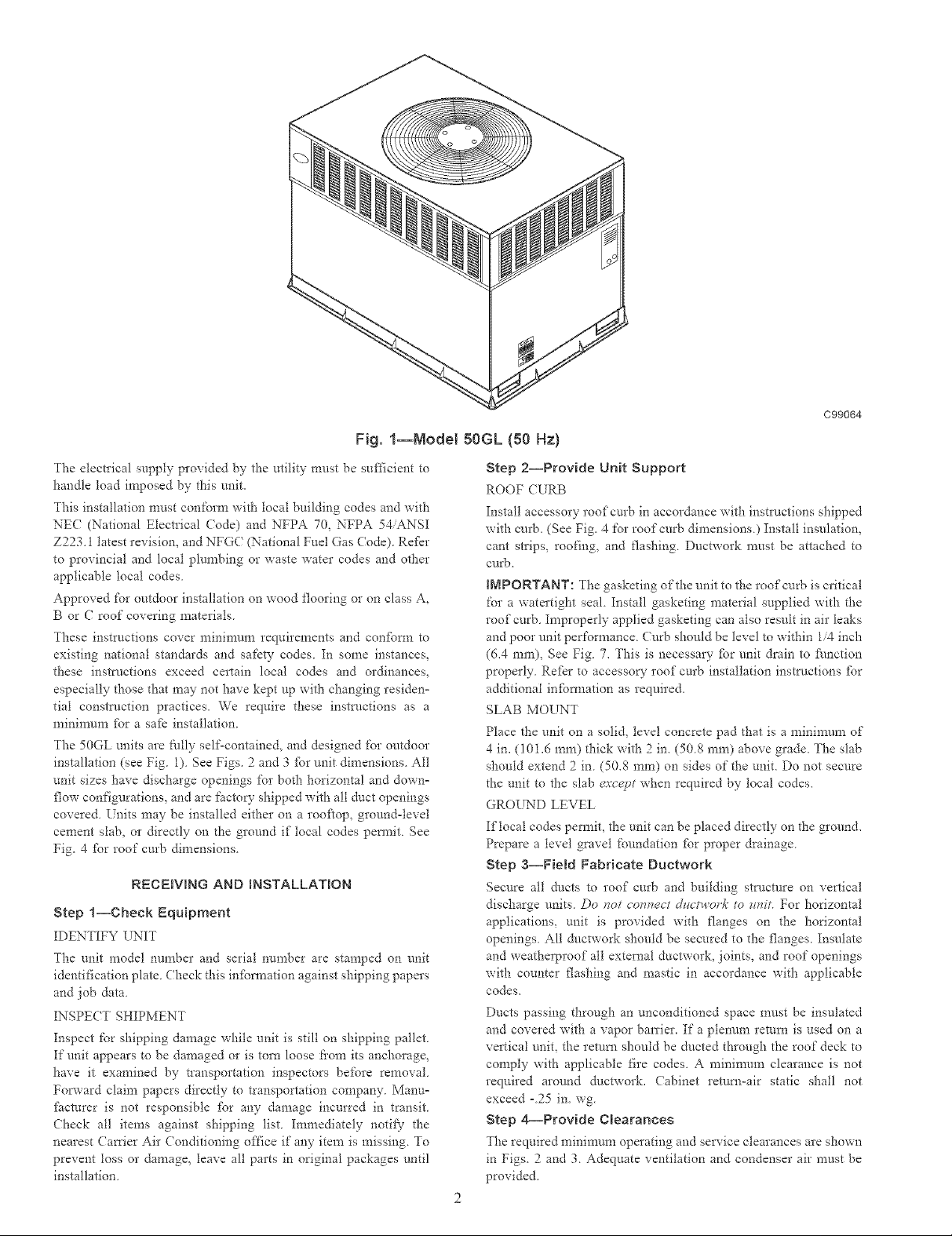
Fig. l--Model 50GL {50 Hz)
The electrical supply provided by the utility must be sufficient to
handle load imposed by this unit.
This installation must conform with local building codes and with
NE( (National Electrical Code) and NFPA 70, NFPA 54/ANSI
Z223.1 latest revision, and NFG( (National Fuel Gas Code). Re_:_r
to provincial and local plumbing or waste water codes and other
applicable local codes.
Approved for outdoor installation on wood flooring or on class A,
B or C roof covering materials.
These instructions cover n_inimum requirements and con_bt'm to
existing national standards and safety codes. In some instances,
these instructions exceed certain local codes and ordinances,
especia!ly those that may not have kept up with changing resideno
tial construction practices. We require these instrl/ctions as a
minimum fbr a safe installation.
The 50GL units are Nlly self-contained, and designed for outdoor
installation (see Fig. 1). See Figs. 2 and 3 t:br unit dimensions. All
unit sizes have discharge openings for both horizontal and down°
flow configurations, and are facto V shipped with all duct openings
covered. Units may be installed either on a rooflop, ground-level
cement slab, or directly on the ground if local codes permit. See
Fig. 4 ibr roof curb dimensions.
RECEBVING AND INSTALLATION
Step 1--Check Equipment
IDENTIFY UNIT
The unit model number and serial nungber are stamped on unit
identification plate Check this information against shipping papers
and job data
INSPECT SHIPMENT
Inspect lk_r shipping damage while unit is still on shipping pallet
If unit appears to be damaged or is torn loose tiom its anchorage,
have it examined by transportation inspectors before removal.
Forward claim papers directly to transportation company. Manuo
fhct*_rer is not responsible fbr any damage incurred in transit.
Check all items against shipping list. Immediately notify the
nearest ( mxier Air Conditioning once if any item is missing. To
prevent toss or damage, leave all parts in original packages until
installation.
C99064
Step 2--Provide Unit Support
ROOF (URB
Install accessory roof curb in accordance with inst_/ctions shipped
with curb. (See Fig. 4 for roof curb dimensions) Install insulation,
cant strips, roofing, and flashing Ductwork must be attached to
curb
INPORTANT: The gasketing of the unit to the roof curb is critical
for a watertight seal. Install gasketing material supplied with the
roof curb. Improperly applied gasketing can also result in air leaks
and poor unit performance. Curb should be level to within 1/4 inch
(6.4 ram), See Fig. 7. This is necessary _br unit drain to Nnction
properly. Refkr to accessow- roof cm'b installation instructions fbr
additional infbm_ation as required.
SLAB MOUNT
Place the unit on a solid, level concrete pad that is a nainimun_ of
4 in. (i01.6 ram) thick wit}* 2 in. (50.8 ram) above grade. The slab
should extend 2 in. (50.8 ram) on sides of the unit. Do not secure
the unit to the slab ea'cc,pt when required by local codes.
GROUND LEVEL
Iftocal codes permit, the unit can be placed directly on the ground.
Prepare a level gravel foundation _br proper drainage.
Step a--Field Fabricate Duetwork
Secure all ducts to roof curb and building structure on vertical
discharge units. Do nut connect dzlctwork to _fmt. For horizontal
applications, unit is provided with flanges on the horizontal
openings. All dtlctwork should be secured to the flanges. Insulate
and weatherproof all external ductwork, joints, and roof openings
with counter flashing and mastic in accordance with applicable
codes.
Ducts passing through an unconditioned space must be insulated
and covered with a vapor barrier. If a plenum return is used on a
vertical unit, the return should be ducted through the roof deck to
comply with applicable fire codes. A minin-mm clearance is not
required around dnctwork. (abinet return-air static shall not
exceed -25 in. wg.
Step 4--Provide Clearances
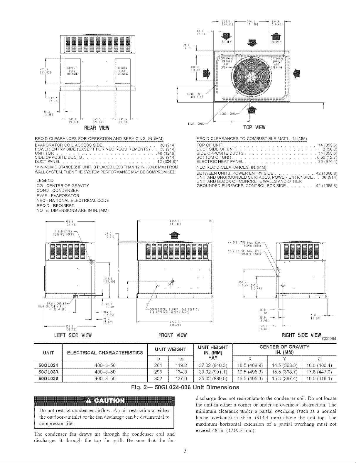
The required minimum opeiating and service clearances are shown
in Figs. 2 and 3. Adequate ventilation and condenser air must be
provided.
Page 3
[9 83] [21 6F] [9 g3_
REAR VmEW
[1600]
,W
REQ'D CLEARANCES FOR OPERATION AND SERVICING IN (MM)
EVAPORATOR COIL ACCESS SIDE ............. 36 1914)
POWER ENTRY SIDE (EXCEPT FOR NEC REQUIREMENTS) . 36 (914)
UNIT TOR ......................... 48 (1219)
SIDE OPPOSITE DUCTS ................... 36 1914)
DUCT PANEL ....................... 12 (304.8)*
*MINIMUM DISTANCES: IF UNIT IS PLACED LESS THAN 12 IN (3048 MM) FROM
VVALL SYSTEM THEN THE SYSTEM PERFORMANCE MAY BE COMPROMISED
LEGEND
CG - CENTER OF GRAVITY
COND - CONDENSER
EVAP - EVAPORATOR
NEC - NATIONAL ELECTRICAL CODE
REQ'D - REQUIRED
NOTE: DIMENSIONS ARE IN IN (MM)
i98 5 - I!93 9
{3i44] [4700]
i 6!os I _ ' '
i [82 45] _.............................
" i I I
,_ol#1;_277 / i,2.
x 22 0 OP I ¢OMPRCSSOR 8_OWER 6AS SECTiOB
8310
[_272]
LEFT SiDE ViEW FRONT ViEW
UNIT
50GL024
50GL030
50GL036
ELECTRICAL CHARACTERISTICS
_ 326 5 & ELECFRICALACC[SSPANEL
[i2 85]
_724
12 85] 12263
[48 28]
UNIT WEIGNT
Ib kg
400-3-50
400-3-50
400-3-50
264 119.2
296 134.3
302 137.0
Fig. 2-- 50GL024-036 Unit Dimensions
REQ'D CLEARANCES TO COMBUSTIBLE MATL IN (MM)
TOP OF UNIT ....................... 14 (355.6)
DUCT SIDE OF UNIT ..................... 2 (50.8)
SIDE OPPOSITE DUCTS .................. 14 (355.6)
BOTTOM OF UNIT ..................... 0.50 (12.7)
ELECTRIC HEAT PANEL .................. 36 (914.4)
NEC REQ'D CLEARANCES. IN.(MM)
BETWEEN UNITS, POWER ENTRY SIDE .......... 42 (1066.8)
UNIT AND UNGROUNDED SURFACES, POWER ENTRY SIDE . 36 (914)
UNIT AND BLOCK OF CONCRETE WALLS AND OTHER
GROUNDED SURFACES, CONTROL BOX SIDE ....... 42 (1066.8)
44 5 [/ 75] CiA K 0
UNIT N_=iGNT
IN. {_,1M}
_A_
37.02 (940.3)
39.02 (991.1)
35.02 (889.5)
POWER E_TRf \
22 2 [0 88] biA
CONTROL E_TRY
4562
[!t£6] 3472
185 (469.9) 14.5 (368.3) 160 (406.4)
195 (495.3) 15.5 (393.7) 176 (447.0)
195 (495.3) 15.3 (387.4) 165 (419.1)
\
[13 67]
5 o
[0 20]
[48i]
RIGHT SiDE ViEW
CENTER OF GRAVITY
IN.(MM)
X Y Z
C00064
Do not restrict condenser airflow. An air restriction at either
the outdoor-air inlet or the J_imdischarge can be detrimental to
compressor tiJ:_.
The condenser _bn draws air through the condenser coil and
discharges it through the top fhn grill, Be sure that the Lm
discharge does not reeJrculate to the condenser coil, Do not locate
the unit in either a corner or under an overhead obstruction The
mininmm clearance under a partial overhang (such as a normal
house overhang) is 36-in, (9144 ram) above the unit top, The
maximum horizontal extension of a partial overhang must not
exceed 48 in, (12192 ram)
Page 4
i i
f!22 I DUCT
58s] _ [ OPENI G 02_1N6
i sUOPL_ 2WN
i I
[16 0i]
402 6
[16 0 ]
L I_ i' [
[4 63] [
' Sw _ ; , j
88 3 35 0 "_3 7 3 _ 371 2
[3 48] [13 83] [[3 67] [13 88]
REARViEW
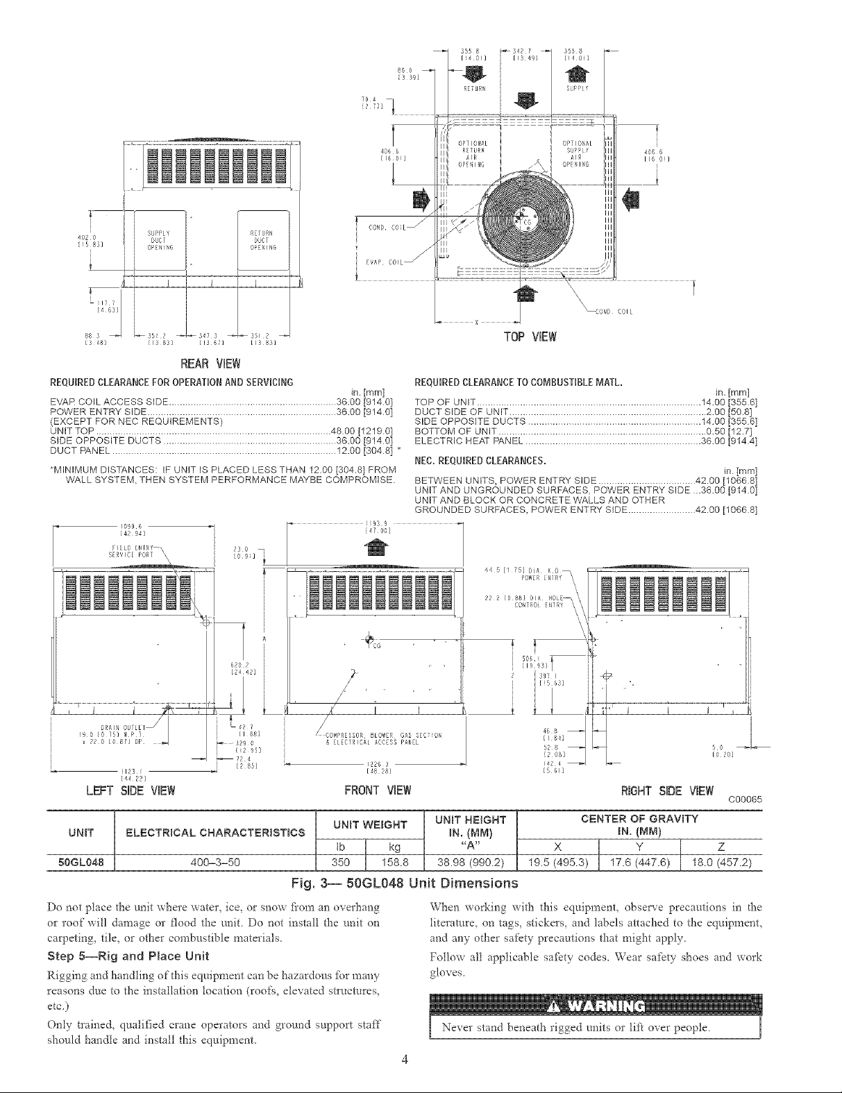
REQUIRED CLEARANCE FOR OPERATION AND SERVICING
EVAR COIL ACCESS SIDE .............................................................. 36.00 [914 O]
POWER ENTRY SIDE ...................................................................... 36.00 [914 0]
(EXCEPT FOR NEC REQUIREMENTS)
UNIT TOP ....................................................................................... 4800 [1219 0]
SIDE OPPOSITE DUCTS ................................................................ 36.00 [914 0]
DUCT PANEL ................................................................................... 12.00 [304 8] _
_MINIMUM DISTANCES: IF UNiT IS PLACED LESS THAN 1200 [304.8] FROM
WALL SYSTEM, THEN SYSTEM PERFORMANCE MAYBE COMPROMISE.
10906
{42 94]
in [mm]
C01L
TOP ViEW
REQUIRED CLEARANCE TO COMBUSTIBLE MATE
TOP OF UNIT ................................................................................... 1400 [355 6]
DUCT SIDE OF UNIT ......................................................................... 200 [50.8]
SIDE OPPOSITE DUCTS ................................................................ 1400 [355 6]
BOTTOM OF UNIT ............................................................................. 050 [12.7]
ELECTRIC HEAT PANEL ................................................................. 3600 [91441
NEC. REQUIRED CLEARANCES,
BETWEEN UNITS, POWER ENTRY SIDE .................................... 42.00 [1066 8]
UNIT AND UNGROUNDED SURFACES. POWER ENTRY SIDE ..3600 [914 0]
UNIT AND BLOCK OR CONCRETE WALLS AND OTHER
GROUNDED SURFACES, POWER ENTRY SIDE ......................... 42.00 [10668 l
d 5 [I 75] DIA K0
POISEI l_2f_
22 2 88 O A 0 / /
CONTRO] EN!RY \ _,_
in. [mml
in [mml
1123 i
[4422]
LEFT SiDE VmEW
UNIT
BL£CTR[CAL CHARACTERISTICS
FRONT ViEW RIOHT SiDE VIEW
UNIT WEIGNT
tb kg
50GL048
400-3-50
350 158.8
Fig. 3-- 50GL048 Unit Dimensions
Do not place the unit where water_ ice, or snow flora an overhang
or roof will damage or flood the mail Do not install the unit on
carpeting_ tile, or other combustible materials,
Step 5--Rig and Place Unit
Rigging and handling of this equipment can be hazardous _br maay
reasons due to the installation location (roofq, elevated stlucmres,
etc,)
Only trained, qualified crane operators and ground support staff
should handle and install this equipment
C00065
UNIT N£1GHT
iN. {_M}
"A"
38.98 (990.2)
19.5 (495.3) 17.6 (447.6) 18.0 (457.2)
CENTER OF GRAVITY
IN. (MM)
X Y Z
When workiag with this equipment, observe precautions in d-_e
literature, on tags, stickers, and labels attached to the equipment,
and aay other safety precautions that might apply,
Follow all applicable safkty codes, Wear safety shoes and work
gloves
Page 5
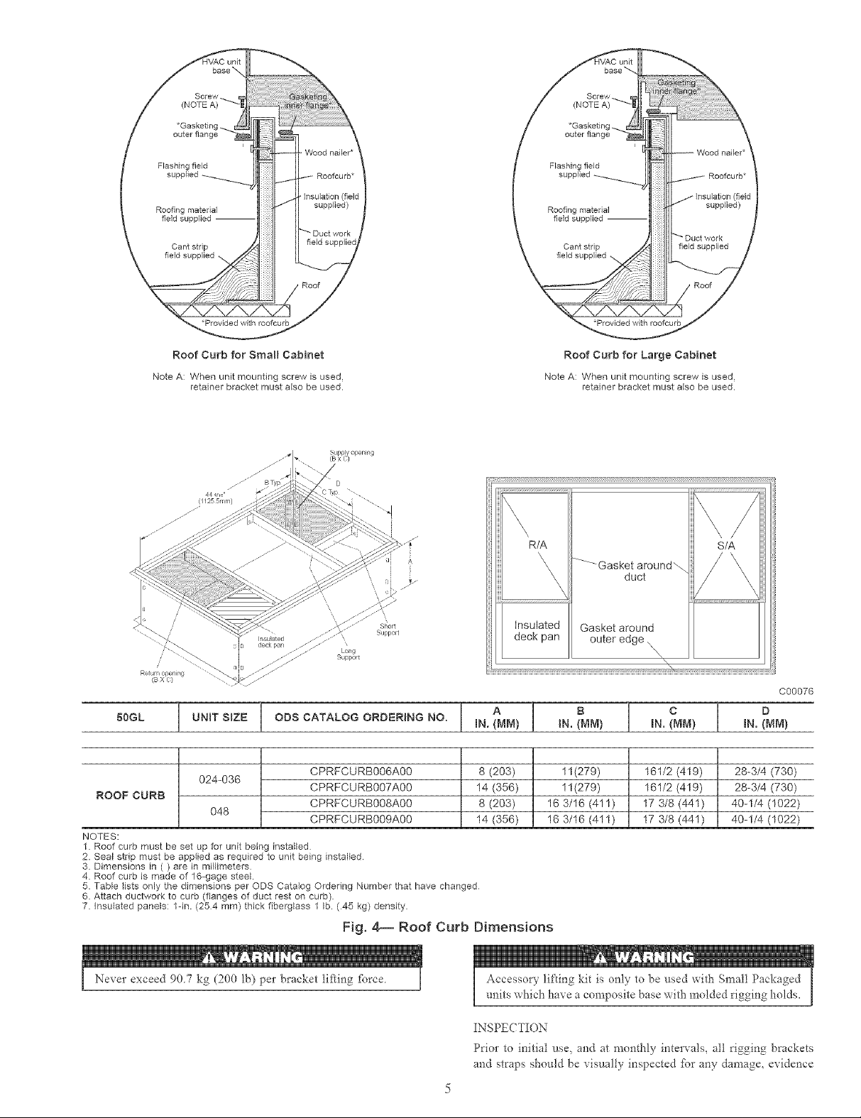
Roof Curb for Small Cabinet
Note A: When unit mounting screw is used,
retainer bracket must also be used.
Roof Curb for Large Cabinet
Note A: When unit mounting screw is used,
retainer bracket must also be used.
R/A
-'-_- Gasket around_
\
\
Suppolt
Long
Support
iB X C}
50GL UNIT SIZE ODS CATALOG ORDERING NO. IN. {MM) IN. {MM) IN. {MM) IN. {MM)
ROOF CURB
NOTES:
1. Roof curb must be set up for unit being installed
2. Seal strip must be applied as required to unit being installed
3. Dimensions in ( ) are in millimeters
4. Roof curb is made of 16-gage steel.
5. Table lists only the dimensions per ODS Catalog Ordering Number that have changed
6. Attach ductwork to curb (flanges of duct rest on curb)
7. Insulated panels: lqn. (254 mm) thick fiberglass 1 lb. (45 kg) density.
i I ° i ° i °
024-036
048
CPRFCURB006A00 8 (203) 11(279) 161/2 (419) 28-3/4 (730)
CPRFCURB007A00 14 (356) 11(279) 161/2 (419) 28-3/4 (730)
CPRFCURB008A00 8 (203) 16 3/16 (411) 17 3/8 (441) 40-1/4 (1022)
CPRFCURB009A00 14 (356) 16 3/16 (411) 17 3/8 (441) 40-1/4 (1022)
insulated
deck pan
Gasket around
duct
outer edge \
/\
\,
Fig. 4===Roof Curb Dimensions
S/A
C00076
INSPECTION
Prior to initial use, and at monthly intervals, all rigging brackets
and straps should be xisualty inspected for any damage, evidence
Page 6
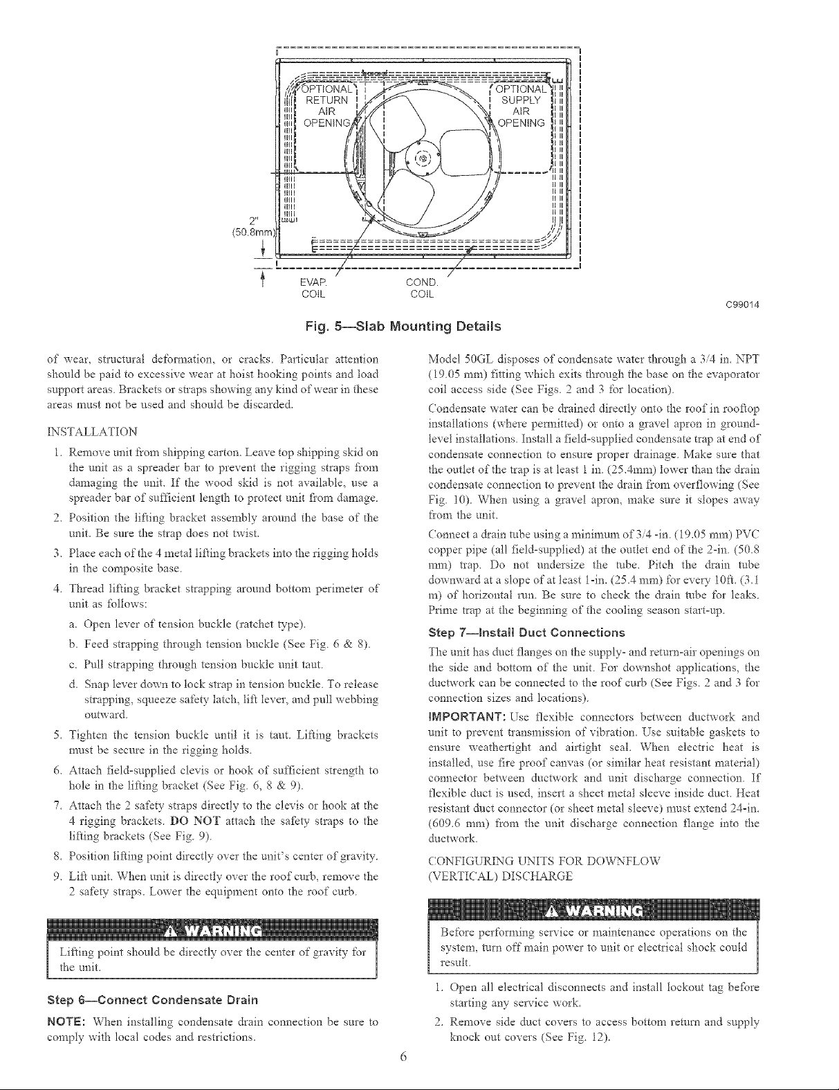
2"
(50 8ran
EVAP. COND.
COIL COIL
Fig. 5--Slab Mounting Details
C99014
of wear, structural det'ormation, or cracks Particular attention
should be paid to excessive wear at hoist hooking points and load
support areas Brackets or straps showing any kind of wear in these
areas must not be used and should be discarded.
INSTALLATION
l. Remove unit t'rom shipping carton. Leave top shipping skid or*
the unit as a spreader bar to prevent the rigging straps fiom
damaging the unit. If the wood skid is not available, use a
spreader bar of sufficient length to protect unit flora damage
2. Position the lifting bracket assembly around the base of the
unit. Be sure the strap does not twist.
3. Place each of the 4 metal lifting brackets into the rigging holds
in the composite base
4. Thread lifting bracket strapping around bottom peiimetei of
unit as follows:
a. Open lever of tension buckle (ratchet type).
b. Feed strapping through tension buckle (See Fig 6 & 8).
c. Pull strapping through tension buckle unit taut
d. Snap lever down to tock strap in tension buckle To release
strapping, squeeze safety tatch, lift teveI, and pull webbing
outward
5. Tighten the tension buckte until it is taut Lifting brackets
n-rest be secure in the rigging holds
6. Attach field=supplied clevis or hook of sufficient strength to
hole in the lifting bracket (See Fig. 6, 8 & 9).
7. Attach the 2 safety straps directly to the clevis or hook at the
4 rigging brackets. DO NOT attach the safety straps to the
lifting brackets (See Fig. 9).
8. Position lifting point directly over the unit's center of gravity.
9. Lift unit. When unit is directly over the roof curb, remove the
2 safety straps. Lower the equipment onto the roof curb.
Model 50GL disposes of condensate water through a 3/4 in. NPT
(1905 ram) fitting which exits through the base on the evaporator
coil access side (See Figs. 2 and 3 for location)
Condensate water can be drained directty onto the roof in rooftop
installations (where pem_itted) or onto a gravel apron in ground-
level installations. Install a field=supplied condensate trap at end of
condensate connection to ensure proper drainage. Make sure that
the outlet of the trap is at least 1 in. (25.4mm) lower than the drain
condensate connection to prevent the &ain f}'om overflowing (See
Fig. i0). When using a gravel apron, make sure it slopes away
/}'ore the unit.
Connect a drain robe using a mininmna of 3/4 -in. ( 19.05 ram) PVC
copper pipe (all field-supplied) at the outlet end of the 2-in. (50.8
ram) trap. Do not undersize the tube. Pitch the drain robe
downward at a slope of at least 1-in. (25.4 ram) for every 1Oft. (3.1
m) of horizontal 1am. Be sure to check the &ain robe for leaks.
Prime trap at the beginning of the cooling season start=up.
Step 7--Install Duct Connections
The unit has duct flanges on the supply- and return=air openings on
the side and bottom of the unit For downshot applications, the
ductwork can be connected to the root" curb (See Figs 2 and 3 for
connection sizes and locations)
IMPORTANT: l_se flexible connectors between ductwork and
unit to prevent transmission of vibration. Use suitable gaskets to
ensure weathertight and airtight seal. When electric heat is
installed, use fire proof canvas (or similar heat resistant material)
connector between ductwork and unit discharge connection. If
flexible duct is used, insert a sheet metal sleeve inside duct. Heat
resistant duct connector (or sheet metal sleeve) must extend 24=in.
(60%6 ram) from the unit discharge connection flange into the
&ctwork.
CONFIGUR1)..:G UNITS FOR DOW_TLOW
(VERTICAL) DISCHARGE
the unit,
Step 6--Connect Condensate Drain
NOTE: When installing condensate drain connection be sure to
comply with local codes and restrictions.
Before performing service or maintenance operations on the
system, mrn off main power to unit or electrical shock could
result
1. Open all electrical disconnects and install lockout tag be%re
starting any service work.
2. Remove side duct covers to access bottom remm and supply
knock out covers (See Fig. 12).
Page 7
DUCTS
'\
\\
SRZE
B
PLACE RIGGING STRAPS IN
BASEPAN SLOT (BELOW R]/ GING HOLDS)
BEFORE RIG/'qNG
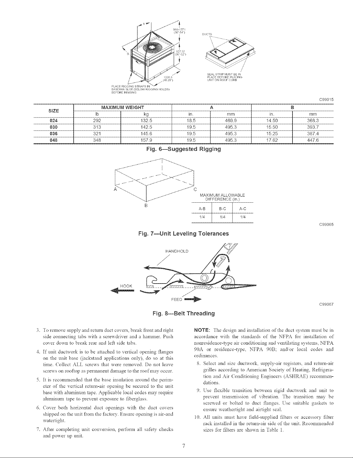
MAXBMUM WEIGHT A B
Ib kg in. mm in. mm
_f/A /;',2,;T:,_7_
/(4828')
PLACE BEFORE PLACING
UNIT ON ROOF CURB
024 292 132.5 18.5 469.9 14.50 368.3
030 313 142.5 19.5 495.3 15.50 393.7
036 321 145.6 19.5 495.3 15.25 387.4
048 348 157.9 19.5 495.3 17.62 447.6
Fig. 6--Suggested Rigging
3
MAXIMUM ALLOWABLE
DIFFERENCE 0n.)
A-B B-C A-C
1/4 1/4 1/4
Fig. 7--Unit Leveling Tolerances
C99015
C99065
HANDHOLD Z<_
HOOK
Fig. 8--BeR Threading
3. To remove supply and return duct covers, break front and right
side connecting tabs with a scre_drixer and a hammer Push
cover do_n to break rear and ld:'t side tabs.
4. If unit ductwork is to be attached to vertical opening flanges
on the unit base 0ackstand applications only), do so at _his
time, Collect ALL screws that were removed, Do not leave
screws on rooftop as permanent damage to the roof may occur
5, It is recommended that the base insulation around the perim°
eter of" the vertical return°air opening be secm'ed to the unit
base with alumintml tape. Applicable local codes may require
aluminum tape to prevent exposure to fiberglass.
6. (;over both horizontal duct openings with the duct covers
shipped on the unit fi'om the _i_ctory. Ensure opening is air-and
watertight.
7. After completing unit conversion, perform all safety checks
and power up unit.
FEED
C99067
NOTE: The design and installation of the duct system must be in
accordance with the standards of the NFPA for installation of
nonresidence-type air conditioning and ventilating systems, NFPA
90A or residence=type, NFPA 90B; and/or local codes and
ordinances.
8 Select and size ductwork, supply-air registers, and return-air
grilles according to American Society of Heating, Ref?igera-
tion and Air Conditioning Engineers (ASHRAE) reeommen=
dations
9. Use flexible transition between rigid ductwork and unit to
prevent transmission of vibration. The transition may be
screwed or bolted to duct flanges. Use suitable gaskets to
ensure weathertight and airtight seal.
10. All units must have field-supplied filters or accessory filter
rack installed in the return-air side of the unit. Recommended
sizes _br filters are shown in Table 1.
Page 8
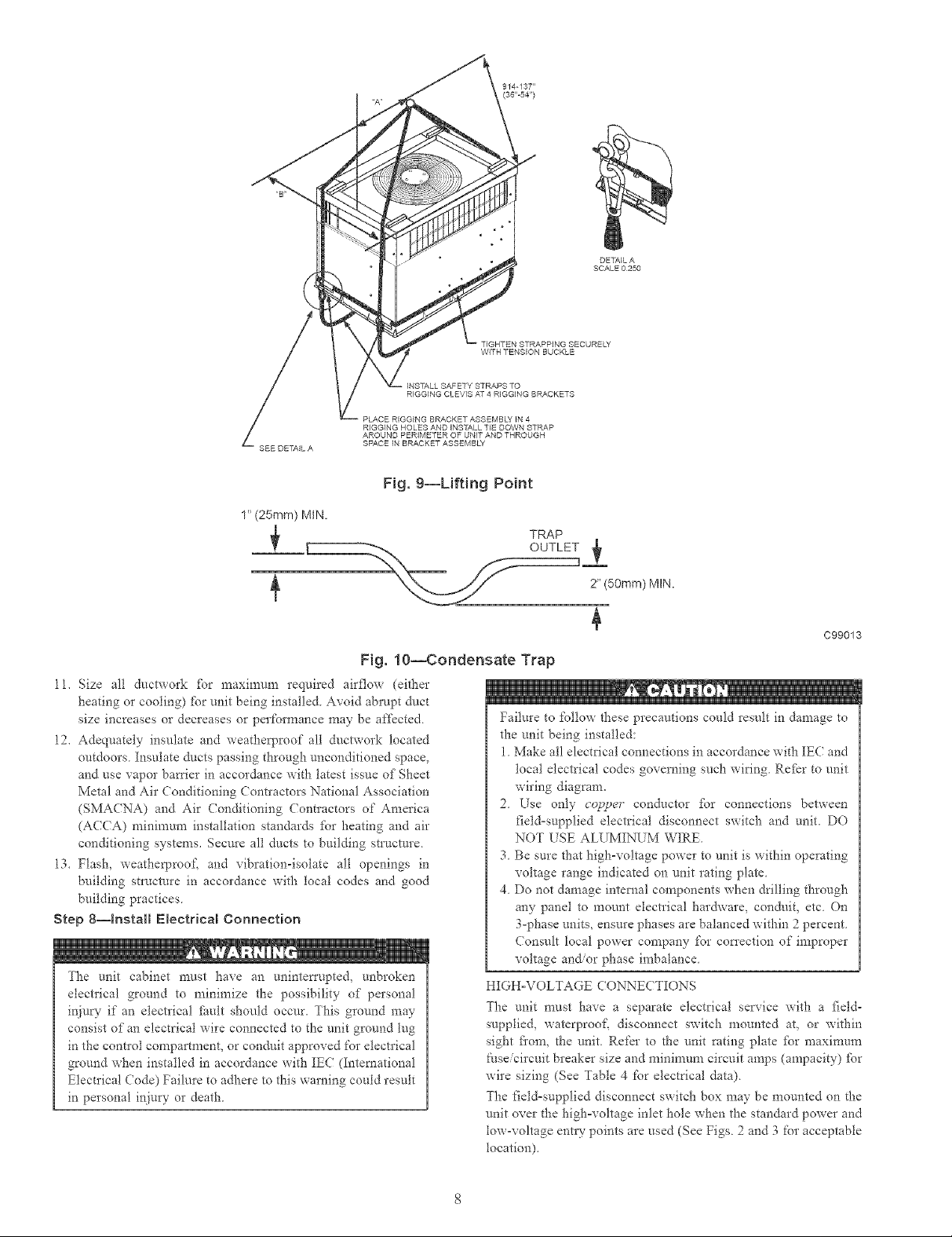
B4STALL SAFETY STRAPS TO
RIGGB4G CLEVIS AT 4 RIGGING BRACKETS
PLACE RIGGING BRACKET ASSEMBLV IN 4
RIGGING HOLES AND INSTALL TIE DOWN STRAP
AROUND PERIMETER OF UNIT AND THROUGH
SEE DETAIL A
SPACE B4 BRACKET ASSEMBL'V
Fig. 9--Lifting Point
1" (25mm) MtN.
Fig. 10--Condensate Trap
11. Size all ductwork %r maxinmm required airflow (either
heating or cooling) fbr unit being installed. Avoid abrupt duct
size increases or decreases or perfom_ance may be affected
12. Adequately insulate and weatherproof all ductwork located
outdoors Insulate ducts passing through unconditioned space,
and use vapor barrier in accordance with latest issue of Sheet
Metal and Air Conditioning Contractors National Association
(SMACNA) and Air (oaditioning Colmactors of America
(ACCA) minimum installation standards fbr heating and air
conditioning systems. Secure all ducts to building structure
13. Flash, weatherproof, and vibration-isolate all openings in
building structure in accordance with local codes and good
building practices
Step 8--Install Electrical Connection
The unit cabinet must have an uaintetTupted, unbroken
electrical ground to minimize the possibility of personal
injury if an electrical _5ult should occur. This ground may
consist of an electrical wire connected to the unit ground tug
in the contlol compartment, or conduit approved for electrical
ground when installed in accordance with IEC (International
Electrical Code) Failure to adhere to this warning could result
in personal injury or death
DETAIL A
SCALE 0250
TIGHTEN STRAPPING SECURELY
WITH TENSION BUCKLE
TRAP
OUTLET
2" (50ram) MIN.
C99013
Failure to %llow these precautions could result in damage to
the unit being installed:
1 Make all electrical connections in accordance with IEC and
local electrical codes governing such wiring Refkr to unit
wiring diagram.
2 Use only cop!_er conductor _br connections between
fieldosupplied electrical disconnect switch and unit. DO
NOT USE ALUMINUM WIRE.
3. Be sure that high-voltage power to unit is within operating
voltage range indicated on unit rating plate.
4. Do not damage internal components when drilling through
any panel to mount electrical hardv,'are, con&fit, etc. On
3-phase units, ensure phases are balanced within 2 percent.
Consult local power company for cot_'ection of improper
voltage aa_or phase imbalance.
HIGHoVOLTAGE CONNECTIONS
The unit must have a separate electrical service with a field-
supplied, waterproof, disconnect switch mounted at, or within
sight fi'om, the unit Refer to the unit rating plate fbr maximum
£aseicircuit breaker size and mininmm circuit amps (ampacity) _br
wire sizing (See Table 4 t'or electrical data)
The field=supplied disconnect switch box may be mounted on the
unit over the highovoltage inlet hole when the standard power and
tow-voltage entry points are used (See Figs 2 and 3 for acceptable
location).
Page 9

Table 1--PhysicN Data-UNt 50GL (50 Hz)-English
UNiT SIZE 024 030 036 048
NOMINAL CAPACITY {ton) 2 2-1/2 3 4
OPERATING WEIGHT (Ib) 264 296 302 350
COMPRESSOR Scroll
REFRIGERANT (R-410A)
Quantity (tb) 4.25 6 7.25 9.75
REFRIGERANT METERING (in) .057 .057 .065 .073
CONDENSER COiL
Rowe...Fins/in.
Face Area (sq, ft.)
CONDENSER FAN
NominN Cfm
Diameter (in.) 1/4._.900 1/4....900 1/4....900 1/3...1340
Motor Bp (Rpm}
EVAPORATOR COIL
Rowe...Finstin.
Face Area (sq. ft.)
EVAPORATOR BLOWER
NominN Airflow (Cfm) 10x10 10x10 10x10 1 lx10
Size (in.) 1/4....1075 1/2....1300 1/2...1300 1...1230
Motor (hp)
RETURN-A_R FILTERS (in.}* 2Ox2O 20x20 20x24 24x30
throwaway
* Requiredfilter sizes shown are based on rated cooling airflow or heating airflow velocity of 300ft/min for throwaway type or 450 tL/minfor high-capacity type. Air filter
pressure drop for non-standard filters must not exceed 0.08 in wg
1._17 1._17 2._17 2...17
10.9 12.7 9.1 12.3
2350 2350 2350 3300
22 22 22 22
3...15 3_.15 3...15 4...15
3.70 3.70 3.70 4.70
800 1000 1200 1600
Table 2--PhysicN Data--Unit 50GL {50 Hz)-SI
UNIT SIZE 024 030 036 048
NOMINAL CAPACITY (kW) 7.0 8.8 10.6 14.1
OPERATING WEIGHT (kg) 119.7 134.3 137.0 158.8
COMPRESSOR Scroll
REFRIGERANT {Ro41OA)
Quantity (kg) 1.93 2.72 3.29 4.42
REFRIGERANT 1.45 1.45 1.65 1.85
METERBNG DEVICE
CONDENSER CORL
Rows_,Finsim.
Face Area (eq. m)
CONDENSER FAN
Nominal L!e
Diameter (ram) .187...15 .187._15 .187...15 .249...22
Motor Hp (r/s)
EVAPORATOR COIL
Rows...Finslm
Face Area (sq. m)
EVAPORATOR BLOWER
Nominal Airflow {Lie) 0.254x0.254 0.254x0.254 0.254x0.254 0.254x0.279
Size {m) 186...17.9 373...21.7 373...21.9 746...20.5
Motor Hp (r/s)
RETURN-AIR FILTERS (ram.)* 508x508 508x508 508x610 610x762
Throwaway
* Required filter sizes shown are based on rated cooling airflow or heating airflow velocRy of 91.5 m/mh3, for throwaway type or 137 m cu/min, for high-capacity type
Air filter pressure drop for non-standard fi{ters must not exceed 203 mm. wg
See unit wiring label and Fig. 13 for ref)rence when making high
voltage connections Proceed as follows to complete the high-
voltage connections to the unit.
Three phase units:
1. Run the high-voltage (L!, L2, L3) and ground leads into the
control box.
2. (onnect ground lead to chassis ground connection.
1...669 1...669 2._669 2...669
1.0 1.2 0.8 1.1
1109 1109 1109 1557
558.8 558.8 558.8 558.8
2...590 3._590 3._590 3._590
0.34 0.34 0.34 0.44
378 472 566 755
3. (onnect field L1 GoBlack wire on connection L1 of the high
voltage temainal block.
4 Connect field wire L2 GoBlack wire on connection L2 of the
high voltage terminal block.
5. ( onnect field wire L3 to Black wire on connection L3 of high
voltage tem_inal block.
6. If Red light blinks on dae phase monitor control board (See
Fig. 17), switch 2 legs on the high voltage terminal block..
U U
Page 10

Airflow
CFM
L/s
TaNe 3--Minimum Airflow for Safe Electr{c Heater
Operation
SIZE
024 030 036
800 I000 1200
378 472 567
s o
o
/ /
SUPPLY RETURN
DUCT DUCT
OPENING OPENING
Fig. 11--Supply and Return Duct Opening
O48
1600
756
1
C99011
DUCT COVERS REMOVED
Fig. 12--VerticN Duct Cover Removed
(ONTROL VOLTAGE (ONNECTIONS
NOTE: Do not use any type of power-stealing thermostat Unit
control problems may result.
Use no. lS American Wire Gage (AWG) color-coded, insulated
(35 (minimum) wires to make the control voltage connections
between the them_ostat and the unit. If the thermostat is located
more than 100 R. fi'om the unit (as measured along the control
voltage wires), use no. 16 AWG color-coded, insulated (35 C
minimum) wires.
C99012
STANDARD CONNECTION
Remove knockout hole located in the electric heat panel adjacent
to the control access panel (See Figs. 2 and 3) Remove the rubber
grommet fi'om the installer's packet (included with unit) and install
grommet in the knockout opening. Provide a drip loop before
running wire through panel.
Rtm the tow-voltage leads flora the thermostat, through the inlet
hole, and into unit towovoltage splice box.
10
Page 11

HIGH VOLTAGE |
p-
POWER LEADS d o-
(SEE UNIT WIRING|
LABEL)
GND
CONTROLBOX
LOW-VO LTAG E
POWER LEADS--
(SEE UNIT
WIRING LABEL)
SPLICE BOX
LEGEND
Field Control-Voltage Wiring
Field High-Voltage Wiring
NOTE: Use blue wire for 3-phase units only.
Fig. 13--High= and Control=Voltage Connections
LEGEND
FLA -- Futt Load Amps
LRA -- Locked Rotor Amps
MCA -- Minimum Circuit Amps
MOCP -- Maximum Overcurrent Protection
RLA -- Rated Load Amps
CKTBKR -- Circuit Breaker
NOTES:
1. In compliance with IEC(International Electrical Code) requirements
for multimotor and combination toad equipment (refer to tEC
Articles 430 and 440), the overcurrent protective device for the
unit shalt be Power Supply fuse.
2. Minimum wire size is based on 60 C copper wire. If other than
60 C wire is used, or if length exceeds wire length in table,
determine size from tEC.
3. Unbalanced 3-Phase Suppty Voltage
Never operate a motor where a phase imbalance in supply volt-
age is greater than 2%. Use the following formula to determine
the percentage of voltage imbalance.
% Voltage imbalance
= 100 x max vottage deviation from average voltage
average voltage
m . m_O
_ I_POWER
4Z:::U o
.... 72- _jsuPPL¥
FIELD-SUPPLIED
FUSED DISCONNECT
YELffL "_ @ THERMOSTAT
G--RN--(G2_ @ _(TYPICAL)
REDgR) __ @
B_RN_C£0- @
EXAMPLE: Supply voltage is 400-3-50.
A B c AB = 393 v
Determine maximum deviation from average voltage.
(AB) 397- 393=4v
(BC) 403- 397 = 6 v
(AC) 397- 396 = 1 v
Maximum deviation is 6 v.
Determine percent of 'voltage imbalance.
% Vottage Imbalance = 100 x --
This amount of phase imbalance is satisfactory as it is below the
maximum allowable 2%.
more than 2%, contact your local electdc utility company
I IMPORTANT: If the supply voltage phase imbalance is
immediately.
J
AC = 396 v
Average Voltage = 393 + 403 + 396
BC = 403 v
= 397
6
397
= 1.5%
3
1192
3
C99010
Fig. 14--Electrical Legend
Locate iS-gage wires leaving control box. These low-voltage
connection leads can be identified by the colors red, green, yellow,
brown, and white. (See Fig. 13.) Ensure the leads are tong enough
to be routed into the low-voltage splice box (located below right
side of control box). Route leads through hole in bottom of control
box and make low-voltage connections as shown in Fig. 13. Secure
all cut wires, so that they do not interfere with operation of unit.
TRANSFORMER PROTECTION
The tmn@)_'7_er is of the energy-limiting type. It is set to
withstand a 30-second overload or shorted secondary condition.
C01054
11
Page 12

UNIT SOGL
SIZE
024 400-3-50
030 400-3-50
03$ 400-3-50
048 400-3-50
(See Eegend fo{Iowing Electrical Data charts)
V-PH°HZ
VOLTAGE
RANGE
Min Max
380 420
380 420
380 420
380 420
Table 4_ElectricN Data--50GL {50Hz)
COMPRESSOR OFM
RLA LRA FLA
4.5 32.0 0.8
5.2 35.0 0.8
6.5 46.0 0.8
6.7 50.0 1.3
IFN ELECTRBC HEAT
FLA NominalKw FLA
1.1 6.5 9.4
8.7 12.6
1.7
2.0
3.9 8.7 12.6
6.5 9.4
8.7 12.6
13.0 18.8
6.5 9.4
8# 12.6
13.0 18.8
6.5 9.4
13.0 18.8
17.4 25.1
POWER SUPPLY DISCONNECT SBZE
MCA FUSE OR CKT. BKR MOCP
7.5 10
19.2 20 -
23.2 25
9.0 10
20.7 20
24.7 25
32.5 35
10.9 15
22.7 25
26.6 30
34.4 35
13.6 15
25.3 30
29.3 30 -
37.0 40
45.0 45
FLA LRA
7 35
18 44
22 48
9 39
20 49
23 52
30 59
11 51
21 61
25 64
32 70
14 58
24 67
28 71
35 77
43 83
PRE-START-UP
Failure to obsela'e the %llowing warnings could result in
serious personal injury or death:
1 Follow recognized saJ[_ty practices and wear protective
goggles when checking or servicing refrigerant system
2 Do not operate compressor or provide any electric power to
unit unless compressor tem_inal cover is in place and
secured.
3. Do not remove compressor terminal cover until all electri=
ca! sources are disconnected and lockout tags are installed.
4. Relieve and recover all refl'igerant fiom both high- and
low-pressure sides of system befbre touching or disturbing
anything inside terminal box if refl'igerant leak is suspected
around compressor temainals.
5. Never attempt to repair soldered connection while refi'ig=
erant system is under pressure.
6. Do not use torch to remove any component. System
contains oil and refi'igerant under pressure. To remove a
component, wear protective goggles and proceed as fol=
lOWS:
a. Shut off electrical power to unit and install lockout tag.
b, Relieve and reclaim all refrigerant fi'om system using
both high° and tow°pressure ports.
c. Cut component connecting tubing with robing cutter and
remove component fi'om unit.
d. Carefldly unsweat remaining tubing stubs when neces°
sary. Oil can ignite when exposed to torch flame.
Proceed as %llows to inspect and prepare the unit %r initial
star:up:
1. Remove access panel.
2. Read and follow instrnctions on all WARNING, CAUTION,
and INFORMATION labels attached to, or shipped with, unit.
3. Make the following inspections:
a. [nspect _br shipping and handling damages such as broken
lines, loose parts, disconnected wires, etc.
b. k_spect for oil at all refi'igerant tubing connections and on
unit base Detecting oil generally indicates a refrigerant
leak. Leak test all refrigerant tubing connections using
electronic leak detector, halide torch, or liquid-soap solu-
tion. If a re['rigerant leak is detected, see (heck _br
Refrigerant Leaks section under Start-Up.
c [nspect all field- and factory-wiring connections Be sure
that connections are completed and tight
d. [nspect coil fins If damaged during shipping and handling,
careflflly straighten fins with a fin comb
Veri£}_ the following conditions:
a Make sure that condenser-fan blade is correctly positioned
in fan orifice Ensure that distance fi'om _m hub to motor is
set to 1/8" (3 175rnm). Adjust if necessary (see Fig. 15)
b. Make sure that air filter(s) is in place.
c Make sure that condensate &sin trap is filled with water to
ensure proper drainage
d. Make sure that all tools and miscellaneous loose parts have
been removed.
START-UP
CHECK FOR REFRIGERATION LEAKS
Proceed as follows to locate and repair a refrigerant leak and to
charge the unit:
1. Locate leak and make sure that refi'igerant system pressure has
been relieved and reclaimed fiom both high- and low-pressure
ports.
2. Repair leak fbllowing accepted practices.
NOTE: Replace filter &ier with factory authorized replacement
whenever d-_e system has been opened fbr repair.
3. (harge unit with R-410A refi'igerant, using a volumetric°
charging cylinder or accurate scale. R@r to zmit rating pZate
/br reqzm'ed cha_ge.
12
Page 13

1/8" (3.175mm) MAX BETWEEN MOTOR SHAFT
MOTOR AND FAN HUB
Fig. 15--Fan Blade Clearance
C99009
STAR7 UP (OOLING SECTION AND MAKE ADJUSTMENT
Complete d_e required procedures given in the Pro-Start=Up
section before starting the unit. Do not jumper any safety
devices when operating the unit Do not operate the compres=
sot when the outdoor temperature is below 55°F/12.8c_(
(unless accesso_- low-ambient kit is installed). Do not rapid=
cycle the compressor. Allow 5 minutes between "on" cycles
to prevent compressor damage.
(HE(KING (OOLING CONTROL OPERATION
Start and check the unit _br proper cooling control operation as
follows:
1. Place room them_ostat SYSTEM switch in OFF position
Observe that blower motor starts when FAN switch is placed
in ON position and shuts down when FAN switch is placed in
AUTO position,
2, Place SYSTEM switch in (OOL position and FAN switch in
AUTO position Set cooling control below room temperature,
Observe that compressor, condenser _n, and evaporator
blower motors start. Observe that cooling cycle shuts down
when control setting is satisfied. The evaporator _hn will
continue to 1am for 30 seconds.
3. When using an auto=changeover room them_ostat, place both
SYSTEM and FAN switches in AUTO positions Obsela'e that
unit operates in heating mode when temperatnre contlol is set
to "call for heating" (above room temperature) and operates in
cooling mode when temperatnre control is set to %all for
cooling" (below room temperature)
INPORTANT: Three=phase, scroll compressor units are
direction-oriented. These units must be checked to ensure proper
compressor 3=phase power lead orientation. If not correct the phase
monitor (See Fig. 17) will not allow power to pass through the
components. Any two of the 3=phase power leads to the unit must
be reversed to correct rotation
CHECKING AND ADJ_ STING REFRIGERANT CHARGE
The refrigerant system is fully charged with R=410A refiigerant,
tested, and factow-sealed.
NOTE: Adjustment of the refrigerant charge is not required
unless the unit is suspected of not having d'*e proper R=410A
charge. The charging label and the tables shown refer to system
temperatures and pressures
INPORTANT: When evaluating the re_iigerant charge, an indi=
cared adjustment to the specified _hcto_" charge must always be
very minimal. If a substantial adjustment is indicated, an abnormal
condition exists somewhere in the cooling system, such as insuf-
ficient airflow across either coil or both coils
Re fi'igerant charge
The amount of reJi'igerant charge is listed on the unit nameplate.
Re_r to the Refiigeration Service Techniques Manual, Refriger-
ants section.
Unit panels must be in place when unit is operating during
charging procedures.
No charge
Use standard evacuating techniques. After evacuating system,
weigh in the specified amount of refiigerant (refer to system data
plate).
Low charge cooling
Measure ontdoor ambient temperature using Cooling Charging
Tables. Vary refligerant until the conditions of the tables are met.
Note that charging tables are different from type normally used.
Tables are based on charging the units to con'ect superheat _br the
various operating conditions. Accurate pressure gauge and tem-
perature sensing devices are required. Connect the pressure gauge
to the service port on the suction line. Mount the temperatore
sensing device on the suction line and insulate it so that the
outdoor ambient does not affect the reading. Indoor air CFM (L/s)
must be within the normal operating range of the unit.
INDOOR AIRFLOW AND AIRFLOW ADJUSTMENTS
For cooling operation, the recommended airflow is 350 to 450
cfm for each 12,000 Btuh of rated cooling capacity (165 to
212 Lis _br each 35 kW of rated cooling capacity).
Table 6 shows cooling airflows at various external static pressures.
Refer to these tables to detem_ine the airflow for the system being
installed.
NOTE: Be sure that all supply= and return-air grilles are open,
free from obstructions, and adiusted properly.
Disconnect electrical power to d-_eunit and install lockont mg
bel:bre changing blower speed. ElectIical shock can cause
personal ir!im'y or death.
Airflow can be changed by changing the lead connections of the
blower motor
All 50GL units are _tctory wired for low speed and may need to be
wired _br medium or high speed in the field
FOR 400 V MOTORS
The motor leads are color coded as _bllows:
To change the speed of the indoor _im motor (IFM), remove fan
motor speed lead fi'om the indoor fan relay (R) and replace with
the lead _br the desired blower motor speed. The motor speed lead
is attached to terminal BM For all speeds, yellow must be
13
Page 14

MAXIMUM WIRE
SIZE 6 AWG. TBI
FIELD
POWERSUPPLY
BL
HEAT SCHEMATIC
USED WITH HEATERS
ACCESSORY
ELECT.HEATI I
OPTION ONLY.
SIZE 2 AWG,
I (BLK) @ 4 (BLK)
3 (BLK) 5 (WHT)
2 (BLK]__ I
I
]
7 {BLK)
6 {BLK)
8 (BLK)
o
. I
-- FMcAPi OR YEL
0TL L BR
3, GRNYEL,z'8(GRNYEL,2
SCHEMATIC
400 3 50
SEE NOTE#2
w2
COMM_
UNIT COMPONENT ARRANGEMENT
OUTDOOR FAN
SECTION
COMPRESSOR INDOOR FAN
SECTION SECTION
COMP
TIT2
50GSO48&060
T3
cAPL_L_
2[]YI
3[]Y2
4_Wl
5@w2
6@G
7@¢
8_ X
O
CONTROLBOXAREA
ELECTIHEA _C
(BLK) HPSIBLK)(BLUI LPS (BLUI
30 (BLK)_ •
HRI & 2 (IO NW)_ I
HRI,2 & 3 (15 KW)J
34(BRN)
HRI, 2, 3, & 4 (20 KW)/
LEGEND
FIELD SPLICE
o TERMINAL (MARKED)
0 TERMINAL {UNMARRED)
o SPLICE
o SPLICE {MARKED)
FACTORY WIRING
FIELD CONTROL WIRING
FIELD POWERWIRING
ACCESSORY OR OPTIONAL
WIRING
TO INDICATE COMMON
POTENTIAL ONLY:
NOT TO REPRESENT
WIRING
R
/EQUIP
GND
24V POWER ENTRY
NOTES:
IIF ANY OF THE ORIGINAL WIRES FURNISHED ARE REPLACED,
IT MUST BE REPLACED WITH TYPE 90 DEGREE C WIRE OR
IT'S EQUIVALENT
R.SEE PRICE PAGES FOR THERMOSTAT AND SUBBASES
3USE 75 DEGREE COPPER CONDUCTORS FOR FIELD INSTALLATION.
4FOR HIGH SPEED IFM,DISCONNECT RED
WIRE FROM IFR3 AND CONNECT BLK WIRE FROM IFM
FOR MEDIUM SP_ED DISCONNECT RED WIRE
FROM IFR;3 AND C6NNECT BLU WIRE FROM IFM
, 36(BRN)
23
ACCESSORY ELECTRIC HEA
HRI (5 KW)
C CONTACTOR
CAP CAPACITOR
CB CIRCUIT BREAKER
COMP COMPRESSOR MOTOR
EQUIP EQUIPMENT
GND GROUND
HPS HIGH PRESSURE SWITCH
HR HEATER RELAY
R INDOOR FAN RELAY
IFM INDOOR FAN MOTOR
LPS LOW PRESSURE SWITCH
OFM OUTDOOR FAN MOTOR
PRM PHASE ROTATION MONITOR
QT QUADRUPLE TERMINAL
TC THERMOSTAT COOLING
TH THERMOSTAT HEATING
TRAN TRANSFORMER
TBI TERMINAL BLOCK POWERLEADS
TB2 TERMINAL BLOCK GROUND LEADS
54
55 (BRN)
R
M
R
V
AN
C
Fig. 16--Wiring Diagram-400-3-50
connected to the jumper wire See Table 9 %r 2 and 3 speed motor
leads.IRws_late remER_ed lend end to mold cutwmct with elTa,ssi,s
parLM.
COOLING SEQUENCE OF OPERATION
With the room them_ostat SYSTEM switch in the COOL position
and the FAN switch in the AUTO position, the cooling sequence
of operation is as follows:
C00062
When the room temperature rises to a point that is slightly above
the cooling control setting of the them_ostat, the thermostat
completes the circuit between thermostat terminal R to temainals Y
and G. These completed circuits through the thermostat connect
contactor coil (C) (through unit wire Y) and blower relay coil (BR)
(through unit wire G) across the 24ov seconda V of transfom?er
(T];-U_N'),
14
Page 15

SUPERHEAT
TEMP
(°C)
0
1
2
3
4
6
7
8
9
10
tl
12
t3
14
t5
16
t7
18
t9
20
21
22
424
1.7
2.8
3.9
5.0
6.1
7.2
8.3
9.4
10.6
11.7
12.8
13.9
15.0
16.1
16.7
17.2
18.3
19.4
20.6
21.7
22.8
23.9
Table 5--Required Suction=Line Temperature (Metric)
SUCTION PRESSURE AT SERVICE PORT (KPA)
443
2.8
3.9
5.0
6.1
7.2
8.3
9.4
10.6
11.7
12.8
13.9
15.0
16.1
17.2
17.8
18.3
19.4
20.6
21.7
22.8
23.9
25.0
463
3.9
5.0
6.1
7.2
8.3
9.4
10.6
11.7
12.8
13.9
15.0
16.1
17.2
18.3
18.9
19.4
20.6
21.7
22.8
23.9
25.0
26.1
483
5.0
6.1
7.2
8.3
9.4
10.6
11.7
12.8
13.9
15.0
16.1
17.2
18.3
19.4
20.0
20.6
21.7
22.8
23.9
25.0
26.1
27.2
503 524 546
6.1 7.2 8.3
7.2 8.3 9.4
8.3 9.4 10.6
9.4 10.6 11.7
10.6 11.7 12.8
11.7 12.8 13.9
12.8 13.9 15.0
13.9 15.0 16.1
15.0 16.1 17.2
16.1 17.2 18.3
17.2 18.3 19.4
18.3 19.4 20.6
19.4 20.6 21.7
20.6 21.7 22.8
21.1 22.2 23.3
21.7 22.8 23.9
22.8 23.9 25.0
23.9 25.0 26.1
25.0 26.1 27.2
26.1 27.2 28.3
27.2 28.3 29.4
28.3 29.4 30.6
568
9.4
10.6
11.7
12.8
13.9
15.0
16.1
17.2
18.3
19.4
20.6
21.7
22.8
23.9
24.4
25.0
26.1
27.2
28.3
29.4
30.6
31.7
591
10.6
11.7
12.8
13.9
15.0
16.1
17.2
18.3
19.4
20.6
21.7
22.8
23.9
25.0
25.6
26.1
27.2
28.3
29.4
30.6
31.7
32.8
Tab{e 6--Superheat Charging Table (Metric)
OUTDOOR EVAPORATOR ENTERING ABRTEMPERATURE (°C WB)
TEMP
(°C) 10 11 12 13 14 15 16 17 18 19 20 21 22
t3 5.0 6.7 7.8 9.4 11.1 11.9 12.8 14.4 16.1 17.8 19.4 20.6 22.2
1G 3.9 5.6 6.7 8.3 10.0 10.8 11.7 13.3 15.0 16.7 18.3 20.0 21.1
t8 - 3.3 5.6 7.2 8.9 9.7 10.6 11.7 13.3 15.0 16.7 18.3 20.0
21 - - 3.9 5.6 7.2 8.1 8.9 10.6 11.7 13.3 15.0 16.7 18.3
24 - - - 3.3 5.0 5.8 6.7 8.3 10.0 11.7 7.8 15.6 17.2
21 .... 2.8 3.6 4.4 6.7 8.3 10.0 11.7 13.9 15.6
29 ...... 4.4 6.1 8.3 10.6 12.2 14.4
32 ...... 2.8 5.0 7.2 8.9 11.1 13.3
38 ....... 3.3 5.6 7.8 10.0 12.2
38 ....... 4.4 6.7 8.3 11.1
41 ....... 2.8 5.0 7.2 9.4
43 ........ 3.3 6.1 8.3
4G ......... 4.4 7.8
Where a dash (-) appears, do not attempt to charge system under these conditions, or refrigerant slugging may occur. Charge must be weighed in.
NOTE: Superheat °C Jsat low-side service port
The normally open contacts of energized contactor (C) close and
complete the circuit through compressor motor ((-OMP) to con=
denser (outdoor) fan motor (OFM). Both motors start instantly.
The set of normally open contacts of energized relay TDR close
and complete the circuit through evaporator blower (indoor) tim
motor (IFM).
NOTE: Once the compressor has started and then has stopped, it
should not be started again until 5 minutes have elapsed.
The cooling cycle remains "on" until the room temperature &ops
to a point that is slightly below the cooling control setting of the
room thermostat. At this point, the thernrostat "breaks" the circuit
between them_ostat terminal R to terminals Y and G. These open
circuits deenergize contactor coil C and relay coil TDR. The
condenser and compressor motors stop. After a 30=second delay,
the blower motor stops. The unit is in a "standby" condition,
waiting for the next "call for cooling" fi'om the room them_ostat.
To ensure continuing high performance, and to minimize the
possibility of premature equipment failure, periodic maintenance
must be performed on this equipment. This cooling unit should be
inspected at least once each year by a qualified service person. To
troubleshoot heating or cooling of units, refer to tables at the back
of the book.
NOTE TO EQUIPMENT O\\'24ER: (onsult your local dealer
about the availability of a maintenance contlact.
MAINTENANCE
15
23
23.3
22.2
21.1
20.0
18.9
17.2
16.7
15.0
13.9
12.8
12.2
11.1
10.0
24
25.0
23.9
22.8
21.7
20.6
19.4
18.3
17.2
16.1
15.0
14.4
13.9
12.8
Page 16

Table 7--Required Suction=Line Temperature (English)
SUPERHEAT SUCTION PRESSURE AT SERVICE PORT (PSBG)
TEMP
(°F) 6115 64.2 67.1 70.0 73.0 76.0 79.2 82.4 85.7
0 35 37 39 41 43 45 47 49 51
2 37 39 41 43 45 47 49 51 53
4 39 41 43 45 47 49 51 53 55
6 41 43 45 47 49 51 53 55 57
8 43 45 47 49 51 53 55 57 59
10 45 47 49 51 53 55 57 59 61
t2 47 49 51 53 55 57 59 61 63
14 49 51 53 55 57 59 61 63 65
t6 51 53 55 57 59 61 63 65 67
18 53 55 57 59 61 63 65 67 69
20 55 57 59 61 63 65 67 69 71
22 57 59 61 63 65 67 69 71 73
24 59 61 63 65 67 69 71 73 75
26 61 63 65 67 69 71 73 75 77
28 63 65 67 69 71 73 75 77 79
30 65 67 69 71 73 75 77 79 81
32 67 69 71 73 75 77 79 81 83
34 69 71 73 75 77 79 81 83 85
36 71 73 75 77 79 81 83 85 87
38 73 75 77 79 81 83 85 87 89
40 75 77 79 81 83 85 87 89 91
Table 8--Superheat Charging Table (English)
OUTDOOR EVAPORATOR ENTERING ABR TEMPERATURE (°FWB)
TEMP
(OF} 50 52 54 56 58 60 62 64 66 68 70 72 74 76
58 9 12 14 17 20 23 26 29 32 35 37 40 42 45
60 7 10 12 15 18 21 24 27 30 33 35 38 40 43
68 -- 6 10 13 16 19 21 24 27 30 33 36 38 41
70 -- -- 7 10 13 16 19 21 24 27 30 33 36 39
78 -- -- -- 6 9 12 15 18 21 24 28 31 34 37
80 .... 5 8 12 15 18 21 25 28 31 35
85 ...... 8 11 15 19 22 26 30 33
90 ...... 5 9 13 16 20 24 27 31
98 ....... 6 10 14 18 22 25 29
100 ........ 8 12 15 20 23 27
108 ........ 5 9 13 17 22 26
110 ......... 6 11 15 20 25
118 .......... 8 14 18 23
Where a dash (-) appears, do not attempt to charge system under these conditions, or refrigerant
NOTE: Superheat °F is at low-side service port
slugging may occur Charge must be weighed in.
Table 9--400oV Motors
Motor Lead Color Codes
3oSPEED 2-SPEED
black = high black = high
white = jumper yellow = jumper
blue = medium
red = low red = low
16
Page 17

Table10--WetCoit Air Delivery
Horizontal and Downflow Discharge*
Unit 50GL (50 Hz) 024=048 (English)
400 VOLT
Unit
50GL024
50GL030
50GL03G
50GL048
* Air delivery values are based on operating voltage of 400-v, wet coil, without filter or electric heater. Deduct filter and electric heater pressure drops to obtain static
pressure available for ducting.
NOTES: 1. Do not operate the unit at a cooling aid_ow that is less than 350 cfm for each 12,000 Btuh (165 L/s for each 35 kW) of rated cooling capacity. Evaporator
2. Dashes indicate portions of table that are beyond the blower motor capacity or are not recommended.
Motor Speed 0.0 0.1 0.2 0.3 0.4 0.5 0.6 0.7 0.8 0.9 1.0
Low
High Cfm - - - 963 833 758 676 - -
Low
High Cfm ..... 1223 1142 1075 1058
Low
High Cfm - - - 1467 1398 1321 1237 1165 1137
Low
High Cfm - 1693 1670 1601 1521 1447 1378 1294 -
coil frosting may occur at airflows below this point
Watts 303 305 303 300 ....
Cfm 969 879 785 687 ....
Watts - - - 435 428 428 422 - -
Watts - 814 853 889 921 954 1002 - -
Cfm - 1189 1115 1041 971 903 833 - -
Watts ..... 700 683 688 755
Watts 552 540 529 523 514 480 - - -
Cfm 1296 1237 1167 1097 1029 952 - - -
Watts - - - 782 765 736 721 780 1002
Watts 692 686 678 664 652 664 736 - -
Cfm 1571 1509 1444 1370 1295 1240 1237 - -
Watts - 1112 930 856 834 825 811 793 -
External Static Pressure (in. wg)
Table 11--Wet Colt Air Delivery
Horizontam and Downflow Discharge*
Unit 50GL (50 Hz) 024=048 (Si)
UNIT
50GL024
80GL030
SOGL036
SOGL048
* Air delivery values are based on operating voltage of 400-v, wet coil, without filter or electric heater. Deduct filter and electric heater pressure drops to obtain static
pressure available for ducting.
1. Dashes indicate portions of table that are beyond the blower motor capacity or are not recommended.
MOTOR SPEED
Low
High
Low
High
Low
High
Low
High
Watts 303 305 303 300 ......
Watts - - 435 428 428 422 - - -
Watts - 814 853 889 92I 954 1002 ....
Watts .... 700 683 688 755
Watts 552 540 529 523 514 480 .....
Watts - - 782 765 736 721 780 1002
Watts 692 686 678 664 652 664 736 ....
Watts - - 1112 930 856 834 825 811 793 - -
O 25 50 75 100 125 150 175 200 225 250
L/s 458 415 371 324 ......
L/S - - 455 393 358 319 - - -
L/s - 561 526 491 458 426 393 ....
L/S .... 577 539 508 499
L/s 612 584 551 518 486 449 .....
L/s - - 693 660 624 584 550 536
L/s 741 712 681 647 611 585 584 ....
L/s - - 799 788 756 718 683 650 611 - -
EXTERNAL STATIC PRESSURE (PA.}
17
Page 18

The ability to properly per%tin maintenance on this equip-
ment requires certain expertise, mechanical skills_ tools, and
equipment If you do not possess these, do not attempt to
peribnn any maintenance on this equipment other than those
procedures recommended in tl_e User's Manual. FAILURE
TO HEED THIS WARNING COULD RESULT IN SERI-
OUS PERSONAL INJURY AND POSSIBLE DAMAGE TO
THIS EQUIPMENT.
Failure to %llow these warnings could result in serious
personal injury:
1. Turn off electrical power to the unit and install lockout tag
before performing any maintenance or sela'ice on the unit.
2. Use extreme caution when removing panels and parts. As
with any mechanical equipment, personal injury can result
fi'om sharp edges, etc.
3. Never place anything combustible either on, or in contact
with, the unit.
Errors made when reconnecting wires may cause improper
and dangerous operation. Label all wires prior to disconnec-
tion when selwicing.
The mininmm maintenance requirements %r this equipment are as
follows:
1. Inspect air filter(s) each month. (?lean or replace when
necessa_
2. Each cooling season, inspect indoor coil, drain, and conden-
sate drain line for cleanliness. (?lean when necessa V,
3. Inspect blower motor and wheel for cleanliness and check
lubrication each heating and cooling season. (lean when
necessa_.
4. Check electrical connections fbr tightness and controls for
proper operation each heating and cooling season. Service
when necessa_'.
AIR FILTER
IMPORTANT: Never operate the unit without a suitable air filter
in the return-air duct system. Always replace the filter with the
same dimensional size and type as originally installed (See Table
1 ibr recommended filter sizes).
Inspect air filter(s) at least once each month and replace
(throwaway-type) or clean (cleanable-type) at least twice during
each heating and cooling season or whenever the filter(s) becomes
clogged with dust and lint.
EVAPORATOR BLOWER AND MOTOR
NOTE: All motors are prelubricated Do not attempt to lubricate
these motors.
For longer life, operating economy, and continuing efficiency,
clean accumulated dirt and grease fiom the blower wheel and
motor annually.
1. Remove arid disassemble blower assembly as %llows:
a. Remove unit access panel.
b. Disconnect motor leads fi'om indoor ihn relay (R).
c. On all units, remove blower assembly flora unit. Remove
screws securing blower to blower partition and slide
assembly out. Be carefld not to tear insulation in blower
compartment.
& Ensure proper reassembly by marking blower wheel and
motor in relation to blower housing before disassembly.
e. Loosen setscrew(s) that secures wheel to motor shaft,
remove screws that secure motor mount brackets to hous-
ing, and slide motor and motor mount out of housing.
2. Remove and clean blower wheel as ibllows:
a. Ensure proper reassembly by marking wheel orientation.
b. Lift wheel fiom housing. When handling and/or cleaning
blower wheel, be sure not to disturb balance weights (clips)
on blower wheel vanes.
c. Remove caked-on dirt from wheel and housing with a
bmsL Remove lint an_or dirt accumulations from wheel
and housing with vacuum cleaner, using soft brush attach-
ment. Remove grease and oil with mild solvent.
& Reassemble wheel into housing.
e. Reassemble motor into housing. Be sure setscrews are
tightened on motor shaR flats and not on round part of
shaft.
i_ Reinstall unit access panel.
3. Restore electrical power to unit. Start unit and check for
proper blower rotation and motor speeds during heating and
cooling cycles.
CONDENSER COIL, EVAPORATOR COIL_ AND (ONDEN-
SATE DRAIN
Inspect the condenser coil, evaporator coil, and condensate drain at
least once each year.
The coils are easily cleaned when @; therefore, inspect and clean
the coils either beibre or after each cooling season. Remove all
obstructions, including weeds and shr_/bs, that interfere with the
airflow through the condenser coil.
Straighten bent fins with a fin comb. If coated with dirt or tint,
clean the coils with a vacuum cleaner, using the soft brl/sh
attachment Be careful not to bend the fins. If coated with oil or
grease, clean the coils with a mild detergent-and-water solution.
Rinse coils with clear water, using a garden hose. Be carefld not to
splash water on motors, insulation, wiring, or air filter(s). For best
results, spray condenser coil fins from inside to outside the unit.
On units with an outer and inner condenser coil, be sure to clean
between the coils. Be sure to flush all dirt and debris from the unit
base.
Inspect the drain and condensate &sin line when inspecting the
coils. (?lean the &sin and condensate &sin line by removing all
foreign matter from the &sin. Flush the &sin arid drain robe with
clear water. Do not splash water on the insulation, motor, wiring,
or air filter(s). If the &sin tube is restricted, clear it with a
"plumbers snake" or similar probe device. Ensure that the auxiliary
drain port above the &sin robe is also clear.
Disconnect and tag electrical power to the unit before
cleaning the blower motor and wheel Failure to adhere to this
warning could cause personal injury or death
To clean the blower motor and wheel:
18
Page 19

CONDENSER FAN
Keep the condenser fan free fi'orn all obstructions to ensure
proper cooling operation. Never place articles on top of the
unit Damage to unit may result.
1. Remove 6 screws holding condenser grille and motor to top
cover
2. Turn motor/grille assemhly upside down on top cover to
expose the fan blade.
3. Inspect the tSn blades tbr cracks or bends.
4. If fan needs to be removed, loosen the setscrew and slide the
tim off the motor shat_.
5. When replacing fan blade, position blade so that the hub is 1/8
in. (3.2 ram) away from the motor end.
6. Ensure that setscrew engages the flat area on the motor shall
when tightening
7. Replace grille.
ELECTRICAL CONTROLS AND WIRING
Inspect and check the electrical controls and wiring annually. Be
.s_lre to tz_'t_ q[f llle electrical po_er to _l_ez_nit and i_sral/ [ocI_ozet
Remove access panel to locate all the eleckical controls and
wiring. Check all electrical connections tbr tightness. Tighten all
screw connections.
After inspecting the electrical contlols and wiring, replace the
access panel. Start tl_e unit, and obsela'e at least one complete
heating cycle and one complete cooling cycle to ensure proper
operation. If discrepancies are observed in either or both operating
cycles_ or if a suspected malNnction has occmxed, check each
electrical component with the proper electrical instrumentation.
RefEr to the unit wiring label when making these checkouts.
NOTE: Ref)r to the heating an_or cooling sequence of operation
in this publication as an aid in determining proper control
operation
REFRIGERANT CIRCUIT
Inspect all refrigerant tubing connections and the unit base for oil
accumulations annually. Detecting oil generally indicates a ref?ig-
erant leak.
System under pressure. Relieve pressure and recover all
ret?igerant before system repair or final unit disposal to avoid
personal inju_' or death. Use all service ports and open all
flow=control devices, including solenoid valves.
If oil is detected or if low cooling performance is suspected,
leak=test all refi'igerant tubing using an electronic leak=detector,
halide torch., or liquid-soap solution. If a refi'igerant leak is
detected, refer to Check for Refrigerant Leaks section.
If no refrigerant leaks are fbund and low cooling performance is
suspected, refer to Checking and Adjusting Reli'igerant Charge
section.
EVAPORATOR AIRFLOW
The heating an_or cooling air=flow does not require checking
unless improper pertbm_ance is suspected. Ira prof_lem exi._ls, I:,e
szlre Nat aN/szll_y)- a_d retzlrn-air grilles are open and fi'eefi'om
ob_strzlctio_s, and that Ills air filter is clean. When necessary, refer
to Indoor Airflow and Airflow Adjustments section to check the
system airflow.
HIGH FLOW VALVES
Located on the compressor hot gas and suction tubes are High
Flow Valves. Large, black plastic caps distinguish those valves
with o-rings located inside the caps These valves cannot be
accessed fbr service in the field. Ensure the plastic caps are in
place and tight or the possibility of refi'igerant leakage could occur.
PHASE MONITOR CONTROL
1 3_hase scroll compressors are rotational sensitive
2. A flashing LED on phase monitor (See Fig. 17) indicates
reverse rotation.
3. This will not allow contactor to be energized
4. Disconnect power to unit and interchange 2 field wiring leads
on unit contactor.
Follow these steps to properly start up the system:
1. Fully back seat (open) liquid and vapor-tube smwice valves.
2. Unit is shipped with valve stem(s) fi'ont seated (closed) and
caps installed. Replace stern caps afler system is opened to
refrigerant flow. Replace caps finger=tight and tighten with
wrench an additional 1/12 mm for back=seating valves (male
square stem).
3. (lose electrical disconnects to energize system.
4. Set room thermostat desired temperature. Be sure set point is
below indoor arubient temperature.
5. Set room thermostat to COOL and fire control to ON or AUTO
mode, as desired. Operate unit for 15 minutes. Check system
refrigerant charge.
SEQUENCE OF OPERATION
Turn on power to indoor and outdoor unit. Transformer is
energized.
On a call tbr cooling, thermostat make circuits R=Y and R=G. On
three phase models with scroll compressors, the units are equipped
with a phase monitor (See Fig. 17) to detect if the incoming power
is correctly phased for compressor operation. If the phasing is
con'ect, circuit R-Y energizes contactor, starting outdoor t_n motor
and compressor circuit. R-G energizes indoor unit blower relay,
starting indoor blower motor on high speed.
NOTE: If the phasing is incolxect, the contactor will not be
energized. To correct the phasing, interchange any two of the three
power connections on the field side.
When the thermostat is satisfied, its contacts open, de=engergizing
contactor and blower relay. Compressor and motors stop.
If indoor unit is equipped with an off-delay circuit, the indoor
blower can be run up to an additional 120 sec to increase the
system efficiency.
P/RON,> SYSTEM ITEMS
METERING DEVICE ACCURATOR PISTON
This metering device is a fixed orifice and is contained in the brass
hex=body in the liquid line
PRESSURE SWITCHES
Pressure switches are protective devices wired into the control
circuit (low voltage). They shut off compressor if"abnormally high
or tow pressures are present in the ref?igeration circuit These
pressure switches are specifically designed to operate with Puron
(R-410A) systems. Other refrigerant pressure switchesmust not be
used as replacements for the Puron (R=410A) air conditioner.
19
Page 20

LED
OFF
FLASHING
ON
GONTAG fOR 24VAC COM
OFF:NO 24VAC
ON:OK
FLASFI _PFIASE PROBLEM
0
L3
Ll
STATUS
No Call for compressor operation
Reversed phase
Normal
Fig. 17--Phase Monitor Control and LED Indicators
A00010
LOSS OF (HARGE LOW-PRESS_ RE SWITCH
This switch is located on d_e liquid line and protects against low
sucdon pressures caused by such events as loss of charge, low
airflow across indoor coil, dirty filters, etc. It opens on a pressure
drop at about 20 psig (138 kpa) If system pressure is above this,
switch should be closed
To check switch:
1. Turn off all power to unit.
2. Install lockout tag
3. Disconnect leads on s_itch.
4. Apply ohmmeter leads across switch. You should have con=
tirmity on a good switch.
NOTE: Because these switches are attached to refi'igeration
system under pressure, it is not advisable to remove this device for
troubleshooting unless you are reasonably certain that a problem
exists. If switch must be removed, remove and recover al! system
charge so that pressure gauges read 0 psi. Never open system
without breaking vacuum with dW nitrogen
HIGH-PRESSURE SWITCH
The high=pressure switch is located in the discharge line and
protects against excessive condenser coil pressure It opens at 610
psig (4206 kpa)
High pressure may be caused by a dirty condenser coil, failed _hn
nmtor, or condenser air recirculation
To check switch:
1. Turn off all power to unit.
2. Install lockout tag
3. Disconnect leads on switch
4. Apply ohmmeter leads across switch. You should have con=
tinuity on a good switch.
(OPELAND PURON SCROLL COMPRESSOR
The compressor used in this product is specil_caily designed to
operate with Puron (R-410A) refrigerant and cannot be iuter-
chaugedo
The compressor is an electrical (as well as mechanical) device
Exercise extreme caution when working near compressors. Power
should be shut off, if possible, fbr most troubleshooting ted>
niques. Refrigerants present additional safety hazards.
Wear safety glasses and g!oves when handling refrigerants.
Keep torches and other ignition sources away fiom refi'iger=
ants and oils. Failure to fbllow this warning can cause a fire,
serious injury, or death.
The scroll compressor pumps refrigerant d_roughout the system by
the interaction of a stationary and an orbiting scroll. The scroll
compressor has no dynamic suction or discharge valves, and it is
more tolerant of stresses caused by debris, liquid slugging, and
flooded starts The compressor is equipped with a phase monitor=
ing device (See Fig. 17) and an internal pressure relief port. The
phase nmnitoring device will not allow power to pass to the
components if the phase is connected incorrectly The internal
compressor pressure relief port is a safety' device, designed to
protect against extreme high pressure. The relief port has an
operating range between 550 arid 625 psi (3792 and 4309 kpa)
diffcrentiai pressure.
The Copeland scroll compressor uses Mobil 3MA POE oil.
This is the on]y oil allowed for oil recharge.
REFRIGERANT
This system uses Puron (R=410A) refiigerant which has
higher operating pressures than R-22 and other refrigerants
No other refrigerant may be used in this system Gage set,
hoses, and recovery system must be designed to handle
Puron If you are unsure, consult the equipment manufi_cturer
Failure to use Puron compatible servicing equipment or
replacement components may result in property" damage or
iajury
COMPRESSOR OIL
The compressor in this system uses a polyolester (POE) oil, Mobil
3MA POE. This oil is extremely hygroscopic, meaning it absorbs
2O
Page 21

AiR CONDITIONER WITH PURON (R-410A) QUICK REFERENCE GUIDE
Puron refrigerant operates at 50-70 percent higher pressures than R-22. Be sure that servicing equipment and replacement components are
designed to operate with Puron. Puron refrigerant cylinders are rose colored.
• Puron refrigerant cylinders manufactured prior to March 1, I999, have a dip tube that allows liquid to flow out of cytinder in upright position.
Cylinders manufactured March 1, 1999 and later DO NOT have a dip tube and MUST be positioned upside down to allow liquid to flow.
• Recovery cylinder service pressure rating must be 400 psig (2758 kpa). DOT 4BA400 or DOT BW400.
Puron systems should be charged with liquid refrigerant. Use a commercial type metering device in the manifold hose.
Manifold sets should be 750 psig (5171 kpa) high-side and 200 psig (1379 kpa) tow-side with 520 psig (3585 kpa) tow-side retard.
Use hoses with 750 psig (5171 kpa) service pressure rating.
Leak detectors should be designed to detect HFC refrigerant.
Puron, as with other HFCs, is only compatible with POE oils.
Vacuum pumps wilt not remove moisture from oil.
Only use factory specified liquid-line filter driers with rated working pressures no less than 600 psig (4137 kpa).
Do not install a suction-line filter drier in liquid line.
POE oils absorb moisture rapidly. Do not expose oil to atmosphere.
POE oils may cause damage to certain plastics and roofing materials.
Wrap all filter driers and service valves with wet cloth when brazing.
A Puron liquid-line filter drier is required on every unit.
Do not use an R-22 TXV.
Never open system to atmosphere while it is under a vacuum.
When system must be opened for service, break vacuum with dry nitrogen and replace fitter driers.
Always replace filter drier after opening system for service.
Do not vent Puron into the atmosphere.
Observe all warnings, cautions, and bold text.
• Do not leave Puron suction line driers in place for more than 72 hrs.
water readily POE oils can absorb 15 times as much water as other
oils designed for HCFC and (F( re_iigerants. Take all necessa_"
precautions to avoid exposure of the oil to the atmosphere.
SERVICING SYSTEMS ON SYNTHETIC ROOFS
POE (polyolester) compressor lubricants are known to cause long
tem_ damage to some synthetic roofing materials. Exposure, even
if immediately cleaned up, may cause embritttement (leading to
cracking) to occur in one year or more. When performing any
sela-ice that may risk exposure of compressor oil Gothe roof, take
appropriate precautions to protect roofing. Procedures which risk
oil leakage include, bug are not limited to, compressor replacement,
repairing refi'igerant leaks, replacing refiigerant components such
as filter drier, pressure switch, metering device, coil, accumulator,
or reversing valve.
Synthetic Roof Precautionar? Procedure
The Following precautions must be taken when dealing with a
synthetic roo£
1, (over extended roof" working area with an impemmable
polyethylene (plastic) drip cloth or tarp (over an approximate
10x 10 ft (3 x31n) area,
2. Cover area in front of the unit service panel with a ter W cloth
shop towel to absorb lubricant spills, prevent run=off;, and
protect drop cloth fiom tears caused by tools or components.
3. Place teiaT cloth shop towel inside unit immediately under
component(s) to be serviced and prevent lubricant run-of£s
through the louvered openings in the unit base.
4 Per%rm required sen'ice.
5. Remove and dispose of any oil contaminated material per
local codes.
LIQUID LINE FILTER DRIER
The filter &ier is specifically designed to operate with Puron. Use
only factory=authorized components. Filter &ier must be replaced
whenever the refi'igerant system is opened. When removing a filter
drier, use a robing cutter to cut d_e drier fi'om the system. Do not
unsweat a fill.or drier from l.he system. Heat from unsweating
will release moisture and contaminants fiom &ier into system.
Puron (R=410A) REFRIGERANT CHARGING
Re_r to unit information plate and charging chart. Some R-410A
refrigerant cylinders cm_tain a dip tube to allow liquid refrig-
erant to flow from cylinder in upright position. For cylinders
equipped with a dip robe, charge Puron units with cylinder in
upright position and a commercial metering device in mani_bld
hose. Charge ref'rigerant into suction=line.
TROUBLESHOOTING
Re*kr to the Tl'ozlbleshootmg Cnolmg chart (Table 7) fbr trouble-
shooting information.
START-UP CHECKLmST
Use the Start=E p checklist to ensure proper start=up procedures are
followed,
2i
Page 22

SYMPTOM
Compressor arid outdoor fan
will not start
Compressor will not start but condenser fan
runs
Compressor cycles (other than normally
satisfying thermostat)
Compressor operates continuously
TaMe 12--Troubleshooting Chart
CAUSE
Power Failure
Fuse blown or circuit breaker tripped
Defective thermostat, contactor, transformer, con-
trol relay, high pressure or loss-of-charge switch
Insufficient line voltage
Incorrect or faulty wiring
Thermostat setting too high
Phase Monitor/Sensing incorrect phasing to compressor
No Power to Componenets
Faulty wiring or loose connections in compressor
circuit
Compressor motor burned out, seized, or
internal overload open
Defective overload
One leg of S-phase power dead
Refrigerant overcharge or undercharge
Defective compressor
Insufficient line voltage
Blocked condenser
Defective ovedoad
Defective thermostat
Faulty condenser4an motor
Restriction in refrigerant system
Dirty air filter
Unit undersized for load
Thermostat set too low
Low refrigerant charge
Air insystem
REMEDY
Call power company
Replace fuse or reset circuit breaker
Replace component
Determine cause and correct
Check wiring diagram and rewire correctly
Lower thermostat setting below room
temperature
Reverse any two incoming power leads to unit.
See if Red light is blinking on phase monitor
Check wiring and repair or replace
Determine cause Replace compressor
Determine cause and replace
Replace fuse or reset circuit breaker.
Determine cause
Recover refrigerant, evacuate system, and
recharge to capacities shown on nameplate
Replace and determine cause
Determine cause and correct
Determine cause and correct
Determine cause and replace
Replace thermostat
Replace
Locate restriction and remove
Replace filter
Decrease _oad or increase unit size
Reset thermostat
Locate leak, repair, and recharge
Recover refdgerant, evacuate system,
and recharge
Condenser coil dirty or restricted
Excessive head pressure
Head pressure too low
Excessive suction pressure
Suction pressure too low
CMan coil or remove restriction
Contactor Stuck Closed
Dirty air filter
Dirty condenser coil
Refrigerant overcharged
Air in system
Condenser air restricted or air short-cycling
Low refrigerant charge
Restriction in Hquid tube
High Heat load
Refrigerant overcharged
Dirty air filter
Low refrigerant charge
Metering device or low side restricted
Insufficient evaporator airflow
Temperature too low in conditioned area
Outdoor ambient below 55°F/12.8C
FieldqnstaIMd filter-drier restricted
Replace failed Contactor
Replace filter
Clean coil
Recover excess refrigerant
Recover refrigerant, evacuate system,
and recharge
Determine cause and correct
Check for leaks, repair and recharge
Remove restriction
Check for source and eliminate
Recover excess refrigerant
Replace filter
Check for leaks, repair and recharge
Remove source of restriction
Increase air quantity
Check filter - replace if necessary
Reset thermostat
Install low-ambient kit
Replace
[-
22
Page 23

L PREUMRNARY INFORMATION
Modet No .............................................................................................................................................................
Serial No ..............................................................................................................................................................
Date .....................................................................................................................................................................
Technician ...........................................................................................................................................................
H. PRE-STARToUp
___ Verify that all packing materials have been removed from unit
___ Verify that condensate connection is installed per installation instructions
___ Check att electrical connections and terminals for tightness
___ Check that indoor (evaporator) air filter is clean and in ptace
___ Verify that unit installation is level
___ Check fan wheel propeller for location in housing and setscrew tightness
HL START-UP
Supply Voltage L1-L2 L2-L3 L3-L1
Compressor Amps L1 L2 L3
Indoor (Evaporator) Fan Amps
TEMPERATURE
Outdoor (Condenser) Air Temperature DB
Return-Air Temperature DB WB
Cooling Air Supply __ DB WB
PRESSURES
Refrigerant Suction psig
Suction Line Temp*
Refrigerant Discharge psig
Discharge Templ-
___ Verify refrigerant charge using charging tables
___ Verify that 3-phase scroll compressor is rotating in correct direction.
START-UPCHECKLIST
(REMOVEANDSTOREINJOBFILE)
* Measured at suction inlet to compressor
1 Measured at liquid line leaving condenser
23
Page 24

Copyright 2002 CARRIER Corp. _ 7310 W. Morris St • Indianapolis. IN 46231 50glc2si
Manufacturer reserves the right to discontinue, or change at any time, specifications or designs without notice and without incurring obligations.
B°°k 1h_ PC 101 Catalog No 005-00026 Printed in U.SA Form 50GL-C2SI Pg 24 7-02 Replaces: 50GL=C1SI
Tab 15al 5a
 Loading...