

Page 1
50ET.QT
HEATING A COOLING
Installation, Start-Up and Service Instructions
Heat Pump and Cooling Unit Chassis Only, Sizes 212-230
CONTENTS
SAFETY CONSIDERATIONS
INTRODUCTION
INSTALLATION
Step 1 — Check Equipment and Jobsite................I
• UNPACK UNIT
• INSPECT EQUIPMENT
• INSPECT WALL SLEEVE
Step 2 — Install Chassis in Wall Sleeve...............1-3
• INSTALL ACCESSORY OUTDOOR GRILLE
• INSTALL ACCESSORY COLD CLIMATE
PACKAGE IF REQUIRED
• SLIDE CHASSIS INTO SLEEVE
Step 3 — Install Accessory Thermostat
and Connect Thermostat Wiring
• TO MOUNT THERMOSTAT IN UNIT
• TO MOUNT THERMOSTAT REMOTELY
Step 4 — Set Indoor Fan Motor Speed...................4
Step 5 — Install Accessory Electric Heater
If Required.................................................................4
START-UP................................................................4,5
SERVICE...................................................................5-I4
Installing and servicing air conditioning equipment
can be hazardous due to system pressure and electrical
components. Only trained and qualified service personnel
should install or service air conditioning equipment.
Untrained personnel can perform basic maintenance,
such as cleaning and replacing filters. All other opera
tions should be performed by trained service personnel.
When working on air conditioning equipment, observe
precautions in literature and on tags and labels attached
to unit.
Follow all safety codes. Wear safety glasses and work
gloves. Use quenching cloth for brazing operations.
Have fire extinguisher available.
.......................................................
.......................................................
SAFETY CONSIDERATIONS
....................................
...........................
A WARNING
Before installing or servicing unit, turn off main
power to system. There may be more than one
disconnect switch. Turn off accessory heater power
if applicable. Electrical shock can cause personal
injury.
_________________________________________
IMPORTANT: Final wiring inspection by local
authorities must be done before chassis is installed
in sleeve.
A WARNING
The Model 50ET,QT chassis is an uncased unit and,
therefore, requires special care in handling to prevent
injury to installer and damage to unit. A portable
lifting device must be used to move and position unit.
Be careful of sharp edges when handling chassis.
Page
I
1
1-4
3,4
Single-Package Units
INTRODUCTION
Install Model 50ET air conditioner or 50QT heat pump
chassis in accessory wall sleeve. See Table 2 for part
numbers. Wall sleeves are shipped separately with accom
panying installation instructions. All electrical power,
ductwork and condensate drain hookups are made at
time of wall sleeve installation.
IMPORTANT; Carrier standard outdoor grille or
deluxe outdoor grille must be ordered separately and
installed in wall sleeve before chassis is installed. Do
not run unit without proper outdoor grille in place.
See Table 2 for part numbers.
INSTALLATION
Step 1 — Check Equipment and Jobsite
UNPACK UNIT — Move to final location. Lift card
board carton off chassis taking special care not to
damage unit.
INSPECT EQUIPMENT for damage prior to installa
tion. To remove metal cover plate, remove 6 screws. File
claim with shipping company if shipment is damaged or
incomplete.
Leave chassis bolted to skid and replace metal cover
plate and carton until ready for installation into wall
sleeve.
INSPECT WALL SLEEVE installation for damage.
Condensate drain pan must be free of debris and installed
in accordance with local building regulations. Electrical
connector on left side of sleeve should be free of dirt,
grease, paint, etc. Connector must be properly wired
before chassis installation. Duct connection panel must
be level and duct connections complete. Do not rest
weight of ductwork on duct connector panel. Inspect
nameplate on sleeve to ensure wire and fuse sizing is
correct for model size and heater accessory to be installed.
NOTE: If remote thermostat location is desired, location
must be determined and field wiring must be installed
before wall completion.
Step 2 — Install Chassis in Wall Sleeve —
Remove sleeve filler panel and save screws.
INSTALL ACCESSORY OUTDOOR GRILLE — In
stall outdoor grille using screws saved Refer to instruc
tions shipped with outdoor grille.
INSTALL ACCESSORY COLD CLIMATE PACK
AGE IF REQUIRED — Cold climate accessory should
be installed where the outdoor ambient temperature
consistently falls below 30 F. Refer to Table 2 for correct
accessory part number. Refer to instructions packaged
with aceessory for installation.
IMPORTANT. Be sure disconnect, per NEC,
installed with the wall sleeve is in OFF position
before proceeding with chassis installation.
Book |1 |1 |4 |4 PC 131 Catalog No 535-078 Printed inUS A Form 50ET,QT-3SI Pgl 5-85 Replaces: 50QT-10SI
Tab Ilbl5ahal5a
Manufacturer reserves the right to discontinue, or change at any time, specifications or designs without notice and without incurring obiigations.
For replacement items use Carrier Specitied Parts
Page 2
50ET,QT
HEATING A COOLING
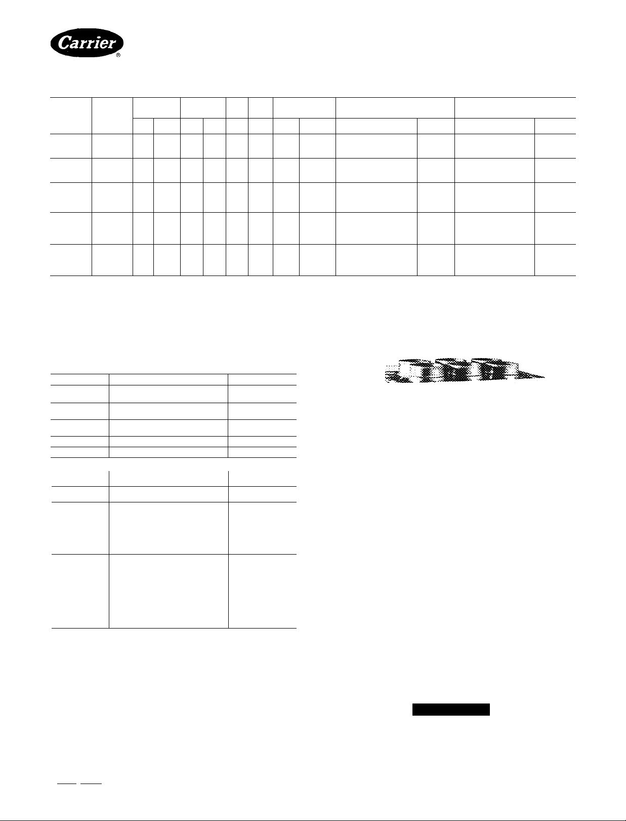
Table 1 — Electrical Data (60 Hz)
OPER
MODEL
50ET/QT
212300
215300 208/230/1
218300
224300ft
230300ft
FLA — Full Load Amps
HACR — Heating, Air Conditioning and Refrigeration
IFM — Indoor Fan Motor
LRA — Locked Rotor Amps
MCA — Minimum Circuit Amps
OFM — Outdoor Fan Motor
RLA — Rated Load Amps
TD — Time Delay
‘Permissible limits of the voltage range at which units will operate
satisfactorily
V/PH
208/230/1
208/230/1 254 187 50
208/230/1 254
208/230/1 254 187
VOLTS*
Max Mint LRA
254 187
254 187 43
187
CO^flPR
37
59
79
RLA
68 1 5
87
9 3
130
169
iPM
FLA
1 5 1 0
1 7 1 5
2 0
2 4 1 5
OFM
FLA
1 0
1 5
ELECTRIC
HEATER
kW
Amps
None
30
9 4/12 5
5.0
18.0/20.8
None
30509 4/12 5
18 0/20 8
None
30
9 4/12 5
50
18 0/20 8
7.5
26.8/31.3
None
50
17 3/20 8
7 5
26 8/31 3
100
36 1/41 7
None
50
17 4/20 8
7 5
26 8/31 3
36.0/41.7
10.0
Single-Package Units
BRANCH CiRCUiT #1
(or Total Unit)
Max TD Fuse or
HACR CktBkr Amps**
15/15
25/30
35/40
20/20
25/30
35/40
20/20
30/35
40/45
50/60
15/15
25/30
35/40
50/60
15/15
30/30
40/40
50/60
tMinimum voltage Is 197 when outdoor ambient temperature exceeds
105 F
^iFiold wiring to be sized per NEC or local codes Use copper wire only
"Maximum dual element fuse size
ttThese units require 2 separate supply circuits Refer to both branch
circuit charts for complete electrical data Two-circuitfused disconnect
must be field supplied
NOTE: Dual values in this table (for example: Electric Heater Amps:
9 4/12 5) apply to 208- and 230-volt connections, respectively
MCA
110/110
22 8/26 6
33,5/37.0
13 4/13 4
25 1/29 0
35 9/39.4
14 8/14 8
26 6/30 5
37 3/40 8
48.3/54.0
2 5/25
24 1/28 5
36 0/41 6
47 6/54 6
3 0/30
24 8/29 0
36 5/42 1
48.0/55.1
BRANCH CiRCUiT #2
(When Used)t
Max TO Fuse or
HACR CktBkr Amps**
-
—
-
25/25
25/25
25/25
25/25
35/35
35/35
35/35
35/35
MCA
-
—
-
17 9/17 9
17 9/17 9
17 9/17 9
17.9/17 9
25/25
25/25
25/25
25/25
Table 2 — Accessories
PART NO.
500T902061 \A/all Sleeve (one)
50QT900081 Wall Sleeve (one)
50QT90301106
500T90302106 Architectural Grille (six) All
S0QT90400102
50QT90401102
50QT90700106 Fresh Air Damper (six)
50QT905001
99TZ900321/
99TZ900361*
99TZ900321/
99TZ900391*
99TZ900291*
99TZ900401*
99TZ900511*
99TZ900501* Electronic, 7-Day Programmable
99TZ900541t
50QT901000
50QT901010
50QT901020
SOQT901030
50QT901040
50QT901050
500T901060
50QT901070
50QT901080
'For remote mounting only
tSuitable for mounting on unit chassis
Standard Aluminum Grille (six) All
Polymer Front Cover (two)
Cold Climate Package (one) All
Cooling Thermostats:
Automatic Changeover All
Manual Changeover All
Heat Pump Thermostats:
Two-Stage Heat, One-Stage Cool
Manual Changeover
Automatic Changeover
Manual Changeover All
Manual Changeover
Electric Heaters (kW)
DESCRiPTiON MODEL 50ET.QT
3
5
75 218
5
7 5 224
10
5
7 5
10
212, 215, 218
224, 230
212, 215, 218
224, 230
212, 215, 218
212, 215, 218
All
224
224
230
230
230
w
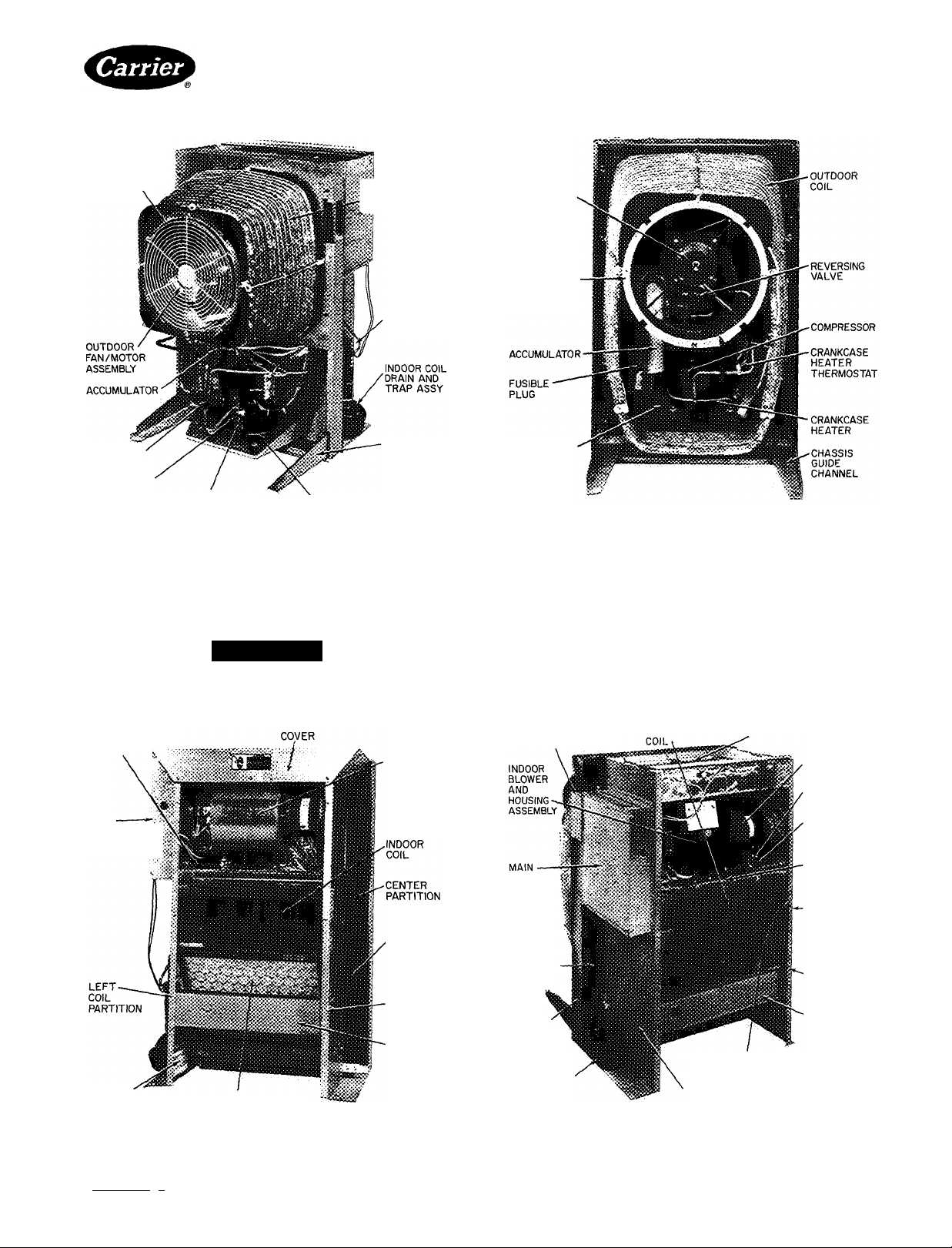
SLIDE CHASSIS INTO SLEEVE — Chassis is heavy.
Portable lifting device must be used. Exercise caution
to be sure forks do not damage chassis components (such
Fig. 1 — Chassis with Accessory Indoor
Polymer Wrapper
as drain connections) while lifting and installing. Guide
chassis into sleeve on indoor side by first placing chassis
guide channels onto lower corners of sleeve. Slide chassis
into sleeve until center partition perimeter meets gasket
provided around outer edge of sleeve. Check electrical
plugs for alignment as chassis is slid into place.
Manufacturer reserves the right to discontinue, or change at any time, specifications or designs without notice and without incurring obiigations.
Bookll II 14 14 PC 131 Catalog No 535-078 Printed in U S A Form 50ET.QT-3SI Pg2 5-85 Replaces: 50QT-10SI
Tab 1b 5al1a|5a For replacement items use Carrier Specilied Parts
Do not release chassis until installed and bolted
completely into sleeve as it may fall out without
warning.
A WARNING
Page 3
50ET,QT
HEATING A C001.ING
OUTDOOR FAN
ORIFICE
REVERSING
VALVE
COMPRESSOR
CRANKCASE HEATER THERMOSTAT
CRANKCASE HEATER
«-OUTDOOR
ÌÌÌ COIL
DEFROST
THERMOSTAT
(NOT VISIBLE)
CHASSIS
GUIDE
CHANNEL
50QT212.215 (shown), 218
Fig. 2 — Outdoor Component Location
Tighten chassis into place by driving 6 lag bolts, pro
vided in separate bag with chassis into nuts provided on
sleeve (see Fig. 3).
Electrical and condensate drain connections are com
plete when chassis is installed correctly into sleeve.
A CAUTION
Tighten lag bolts uniformly. Failure to do so may
cause misalignment and poor electrical connection.
ACCURATER'^“
DEVICE
LOCATION
MAIN
CONTROL
BOX
COVER
ELECTRIC HEATER COMPARTMENT
INDOOR
BLOWER AND
MOTOR
ASSEMBLY
COMPRESSOR
SUCTION
PRESSURE
PORT
LOCATION
Single-Package Units
OUTDOOR
FAN MOTOR
(PROPELLER
FAN AND GUARD
REMOVED)
OUTDOOR FAN
ORIFICE
COMPRESSOR
MOUNTING
PAN
50QT224 (Shown), 230
Step 3 — Install Accessory Thermostat and
Connect Thermostat Wiring — Accessory thermo
stat can be installed on the 50ET,QT chassis or in a
remote location.
TO MOUNT THERMOSTAT IN UNIT-
1. Remove metal cover plate by removing 6 screws.
2. Locate and install subbase onto thermostat bracket
running between right and left coil partition (see
Fig. 3). Push field-supplied thermostat wires through
hole provided.
SLEEVE JUNCTION BOX
ACCESS PLATE
CONTROL
BOX
(SLIDES
OUT FOR
SERVICE)
CHASSIS
MOUNTING
BOLTS (6)
INDOOR
ACCESSORY ELECTRIC HEATER
LOW-PRESSURE
SWITCH
DEFROST
THERMOSTAT
COMPRESSOR
SUCTION
SERVICE
PORT
(NOT VISIBLE)
CENTER
PARTITION
INDOOR
CONDENSATE
DRAIN
50QT224,230
INDOOR
NAMEPLATE
INDOOR AIR FILTER
50QT212,215,218
THERMOSTAT
MOUNTING
BRACKET
Fig. 3 — Indoor Component Location
Book|1 II 14 14 PC131 Catalog No 535-078 PrintedinUSA Form 50ET,QT~3SI Pg3 5-85 Replaces; 50QT-10SI
- • For replacement Hems use Carrier Specilled Parts.
Manufacturer reserves the right to discontinue, or change at any time, specifications or designs without notice and without incurring obligations.
INDOOR AIR FILTER LOCATION
(NOT SHOWN)
LEFT COIL PARTITION
THERMOSTAT
MOUNTING
BRACKET
Page 4
50ET,QT
HEATING A COOLING
(5>
S>]
(5>
THERMOSTAT AND
SUBBASE (SEE BELOW)
THERMOSTAT
99TZ900321 99TZ900361
99TZ900321
COOLING UNIT WITH ELECTRIC HEAT HEAT PUMP WITH SUPPLEMENTAL ELECTRIC HEAT
JM.
JH
WIRES FROM
JZL
UNIT CONTROL BOX
_0_
SUBBASE
99TZ900391
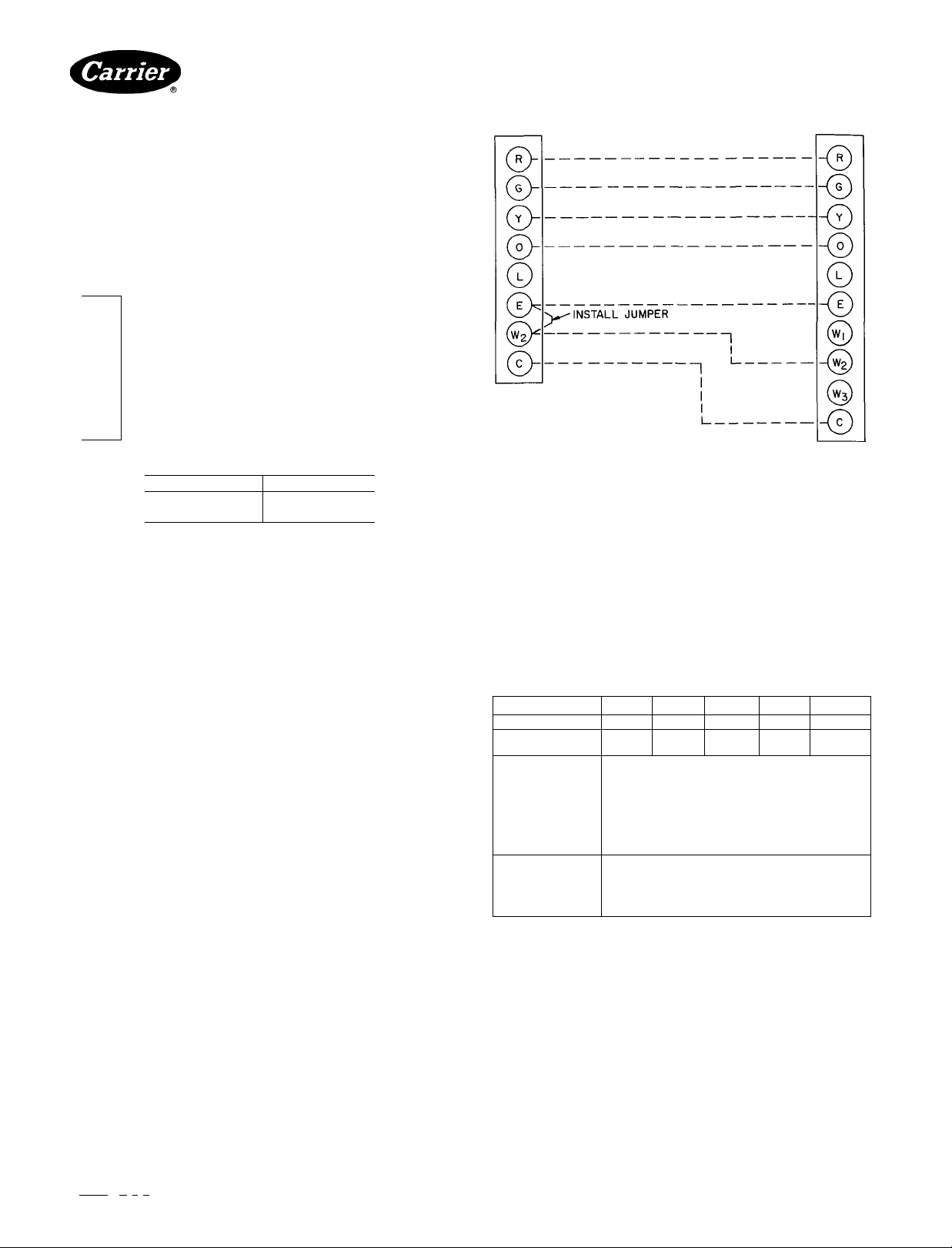
Fig. 4 — Thermostat Connection Diagrams — 50ET,QT
Single-Package Units
UNIT CONTROL BOX
WIRING TERMINAL BOARD
THERMOSTAT/SUBBASE
99TZ900291
99TZ900401
99TZ900511
99TZ900541
3. Route thermostat wires through hole located on left
coil partition and up to low-voltage wire entrance
hole on control box front cover.
4. Remove 2 screws and slide control box to expose
low-voltage terminals. Attach wires to appropriate
terminals as shown on unit wiring diagram. See Fig. 4.
5. Attach thermostat to subbase and snap on thermostat
cover.
6. Cut and remove insulation from hole in metal cover
plate.
7. Replace metal cover plate.
8. Install accessory polymer front cover as described in
instructions shipped with accessory cover. Cut
rectangular hole for thermostat as indicated by mark
in back of cover.
TO MOUNT THERMOSTAT REMOTELY-
1. Pull field-supplied thermostat wires previously
installed up into wire entrance hole on control box
front cover and connect wires as described in Step 3,
paragraph 4, above.
2. Connect other ends of thermostat wires, hanging from
the wall at their remote location, securely into subbase
at appropriate terminals specified in unit wiring
diagram. See Fig. 4.
3 Mount subbase onto wall.
4. Attach thermostat to subbase. Snap on cover and
install chassis indoor cover.
Step 4 — Set Indoor Fan Motor Speed — All
units are factory wired for low fan speed. Higherexternal
static pressure requirements can be met by wiring motor
for higher fan speed. See Table 3.
Step 5 — Install Accessory Electric Heater,
If Required — Refer to instructions packaged with
accessory heater. See Table 2 for part numbers.
» Table 3 — Service Data
SIZE
MODEL 50
R-22 CHARGE* (lb)
Refrig Control
INDOOR FAN
Rotationt
Rpm
Diameter (in.)
Width (In.)
Range (cfm)
Motor Hp
OUTDOOR FAN
Ctm
Rpm
Diameter (In)
Motor Hp
CCW — Counterclockwise
CW — Clockwise
‘Factory refrigerant charge
tLooking at fan motor shaft
212
ET I QT
2 3 I 2 7
215
ET lOT ET 1 QT
23)27
AccuRa
CW I CW I CW I CCW I CCW
1580 1550 1570 1675 1675
430/ 1 550/ 1 575/ 1 885/ 1 1025/
Propeller, Direct Drive, Single Speed
1700 1 1700 1 2000 1 2000 1 2000
218
3 1 1 3 75
ter'" BypaE
Centrifugal Blower,
Direct Drive, 2-Speed
6 1 6 1 6 1 7 1 7
8
375 475 480 800 960
V. 1 '/, 1 % 1 '/4 1 '/4
1125
15
’/b
224 230
ET 1 QT ET 1 QT
4.0 1 4 5
s Type
39)47
START-UP
Crankcase Heater — The 50QT compressor is
equipped with a crankcase heater that is thermostatically
activated in cold weather. (See Fig. 2 and 3.) If tempera
ture is below 65 F, operate crankcase heater 24 hours
before starting unit. To energize crankcase heater only,
after chassis installation, set thermostat to ^^
position (for thermostat mounted on the chassis) or OFF
position (for remote-mounted thermostat) and turn on
unit power at disconnect switch.
t
Bookn 11 |4 |4 PC 131 Catalog No 535-078 PrintedinUSA Form 50ET.QT-3SI Pg4 5-85 Replaces 50QT-10SI
Tab llbisahalsa
Manufacturer reserves the right to discontinue, or change at any time, specifications or designs without notice and without incurring obiigations.
For replacement items use Carrier Specified Parts
Page 5
50ET,QT
HEATING A COOLING
To Start Unit — Check that main power is on and,
if temperature is below 65 F, that compressor crankcase
heater has been energized for at least 24 hours.
1. Set selector switch at <; -O—^ if thermostat is
mounted on chassis, or at OFF if thermostat accessory
is remote mounted.
2. Set fan switch as desired (FAN) (AUTO.).
3. Set thermostat lever at the desired temperature.
4. Set selector .switch at HEAT or COOL. Check sy.stem
refrigerant charge. See Refrigerant Charging.
SERVICE
Service Port Connections — High and low side
pressure connections are accessible from the indoor
portion of the unit for charging. (See Fig. 3.)
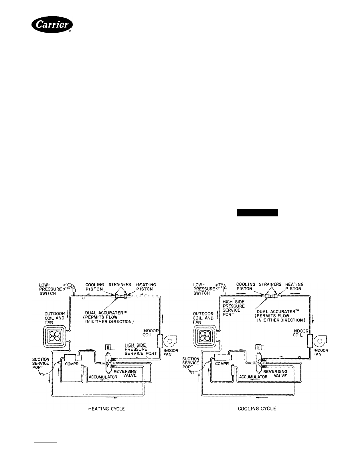
Low-Pressure Switch (50QT only) (Safety
Control) is located on liquid line downstream of Accu-
Rater™ control during cooling mode (or upstream of
AccuRater control during heating mode). Switch opens
at 5 psig and shuts down compressor to protect it from
overheating if refrigerant charge is too low.
High-Pressure Relief Valve (Safety Control) is
located in compressor. Relief valve opens at a pressure
differential of approximately 450 ± 50 psi between
suction (low side) and discharge (high side) to allow
pressure equalization.
Internal Current and Temperature Sensitive
Overload (Safety Control) resets automatically
when compressor motor temperature drops to a safe level
(overloads may require up to one hour to reset). When an
internal overload is suspected of being open, check by
using an ohmmeter or continuity tester. If necessary,
refer to Carrier Standard Service Techniques Manual,
Chapter 2, Electrical, for complete instructions.
Defrost Control consisting of a control board and
defrost thermostat, interrupts normal system heating
operation to remove frost and iee formation on outdoor
Single-Package Units
coil. Frost impairs unit performance. Defrost control
simultaneously stops outdoor fan, energizes reversing
valve solenoid to switch system into cooling cycle (out
door unit as condenser, indoor unit as evaporator), and
activates accessory electric heater. Unit can defrost every
90 minutes, but will do so only if outdoor temperatures
are in the frosting temperature zone.
For heat pump to defrost, 2 eonditions are necessary;
1 Defrost circuit board contacts must be closed.
2. Coil temperature must be cold enough to cause defrost
thermostat contacts to close.
Contacts clo.se at 27 ±5 F. Every 90 minutes of elap.sed
running time, the defrost circuit board contacts close for
10 seconds. If the defrost thermostat contacts are closed,
the unit defrosts The defrost circuit board limits defrost
ing period to 10 minutes. Normally the frost is removed
and the defrost thermostat contacts will open to terminate
defrosting before 10 minutes have elapsed. Defrost
thermostat contacts open at 80 ±5 F. When defrosting is
terminated, the outdoor fan motor is energized and
reversing valve solenoid is de-energized, returning unit
to heating cycle.
HEAT PUMP CIRCUITS shown in Fig. 5 are refrig
erant flow diagrams for heating and cooling cycles.
Refrigerant Charging
A CAUTION
To prevent personal injury, wear safety glasses and
gloves when handling refrigerant.
Do not overcharge system. An overcharge can
cause compressor damage.
Unit refrigerant system is factory charged. When
recharging is necessary, weigh in total charge indicated
in Table 3. (Charge must be weighed in during heating
season.) Remove any refrigerant remaining in system
before recharging. If system has lost complete charge.
3 Unit Piping
Fig. 5 — 50QT Refrigerant Flow Diagrams
Manulacturer reserves the right to discontinue, or change at any time, specifications or designs without notice and without incurring obiigations.
Bookll h |4 |4 PC131 Catalog No 535-078 PrintedinUSA Form 50ET,QT-3S1 Pg5 5-85 Replaces: 50QT-10SI
FROcTlT^r^ Pgj replacement items use Carrier Specified Parts
Page 6

50ET,QT
HEATING A COOLING
triple-evacuate system to 5000 microns (29.7 in. vacuum)
before recharging. Service port connections are provided
on unit suction and discharge lines for evacuation and
charging. (See Fig. 5 for service port location.) Dial-acharge charging cylinder is an accurate device used to
recharge systems by weight. These cylinders are available
at refrigeration supply firms.
To check and/or adjust charge during cooling season,
use Cooling Cycle Charging Charts (Fig. 6, 8, 10, 12, 14)
and follow Charging Chart Method below. The charging
chart may also be used as an alternate method of recharg
ing system.
To check svsiem operation during heating cycle, use
Heating Cycle Operation Check Chart (Fig. 7, 9, 11, 13,
15). These charts indicate whether a correct relationship
exists between system operating pressures and air tem
peratures entering unit. If pressure and temperature
lines do not intersect on chart, the system refrigerant
charge may not be correct or other system abnormalities
may exist. Do not use Operating Check Charts to adjust
refrigerant charge. Weigh charge into system.
Single-Package Units
COOLING CYCLE CHARGING CHART
METHOD
1. Operate unit a minimum of 10 minutes before check
ing charge, and after each charge adjustment.
2. Measure suction pressure by attaching a gage to unit
suction service port. (See Fig. 5 for correct service
port location.)
3 Measure outdoor (coil inlet) air dry-bulb tempera
ture. Use service thermometer.
4. Using a sling psychrometer, measure wet-bulb tem
perature of air entering indoor fan coil.
5. Refer to Charging Chart. Locate on curves where
outdoor air dry-bulb and indoor air wet-bulb tem
perature lines intersect.
6. From intersect point, project vertically downward to
chart suction pressure line. Compare chart suction
pressure to unit suction pressure (step 2).
7. If unit suction pressure is lower than chart pressure,
add refrigerant to system until chart pressure is
reached If unit suction pressure is higher than chart
pressure, remove refrigerant until chart pressure
is reached.
t
70 72 74 76 78 80 82 84 86 88 90 92
SUCTION PRESSURE (PSIG)
Fig. 6 — 50ET.QT212 Cooling Cycle
B^k|1
Tab ilb|5allal5a
Manufacturer reserves the right to discontinue, or change at any time, specifications or designs without notice and without incurring obiigatlons.
[ 1
|4 |4 PC131 Catalog No 535-078 PrIntedinUSA Form 50ET,QT-3SI Pg6 5-85 Replaces: 50QT-10SI
Charging Chart
For replacement items use Carrier Specified Parts
Fig. 7 — 50QT212 Heating Operation
t
Check Chart
Page 7

50ET,QT
HEATING A COOLING
Single-Package Units
NOT AVAILABLE
AT TIME OF
PRINTING
64 66 68 70 7Z 74 76 78 80 82 84 86
SUCTION PRESSURE (PSIG)
Fig. 8 — 50ET,QT215 Cooling Cycle
Charging Chart
Fig. 10 — 50ET.QT218 Cooling Cycle
Charging Chart
NOT AVAILABLE
AT TIME OF
PRINTING
#
10 20 30 40 50 60
Fig. 9 — 50QT215 Heating Operation
Manufacturer reserves the rtght to dtsconttnue, or change at any ttme, spectlicattons or destgns without notice and without incurring obtigations.
k|1 |1 |4 |4 PC131 Catalog No 535-078 PrintedinUSA Form50ET,QT-3SI Pg7 5-85 Replaces: 50QT-10SI
Book
Tab Ilbl5alla|5a For replacement items use Carrier Specified Parts
SUCTION PRESSURE (PSIG)
Check Chart
Fig. 11 — 50QT218 Heating Operation
Check Chart
Page 8

50ET.QT
HEATING A COOLING
Single-Package Units
70 72 74 76 78 80 82 84 86 88 90 92
SUCTION PRESSURE (PSIG)
Fig. 12 — 50ET,QT224 Cooling Cycle
Charging Chart
Fig. 14 — 50ET.QT230 Cooling Cycle
Charging Chart
10 20 30 40 50 60
Fig. 13 — 50QT224 Heating Operation
^ok(1 |1 |4 14_ PC131 Catalog No 535-078 PrintedinUSA Form 50ET.QT-3SI Pg8 5-85 Replaces: 50QTTab hbisahalsa
Manufacturer reserves the right to discontinue, or change at any time, specilications or designs without notice and without incurring obiigations.
SUCTION PRESSURE (PSIG)
Fig. 15 — 50QT230 Heating Operation
Check Chart
For replacement items use Carrier Specified Parts
I
Check Chart
Page 9

50ET,QT
HEATING A COOLING
AccuRater™ Device (Dual-Piston Type)
Servicing — See Fig. 16 for AccuRater components.
m
The pistons have a refrigerant metering orifice through
them. The retainers form a stop for the pistons in the
refrigerant bypass mode, and a sealing surface for liquid
line flare connection. To clean or replace piston;
1. Shut off power to unit.
2. Protect area around unit to prevent damage to
interior, furnishings, etc.
3. Remove refrigerant from unit.
4. Remove liquid line flare connections from Accu
Rater. See Fig. 3 for AccuRater location.
5. Note position of arrow on AccuRater body in
relation to unit.
6. Pull retainer out of body. Be careful not to scratch
flare sealing surface. If retainer does not pull out
easily, carefully use locking pliers to remove
retainer. Replace scratched or damaged retainer.
7. Slide piston out by inserting a small soft wire through
metering hole (18-gage thermostat wire). Check that
metering hole, sealing surface around piston cones
and fluted portion of piston are not damaged.
8. See chart on indoor blower scroll for illustration of
proper arrangement and sizes of pistons.
9. Clean piston refrigerant metering orifice.
10. Replace retainer 0-ring before reassembling Accu
Rater. Carrier O-ring Part No. is 99CC501052.
LIQUID LINE STRAINERS (protect AccuRater), are
made of wire mesh and located in the liquid line on each
side of the AccuRater. The strainers are pressed into the
line. Remove strainer by threading a #10 sheet metal
screw into strainer and pulling the screw with pliers.
Single-Package Units
Compressor Removal — (Refer to Fig. 2.)
IMPORTANT: Compressor cannot be removed
from an installed chassis. Remove chassis from
sleeve, then bring to service truck or dealer shop
before removing compressor.
See Table 4 for compressor information. Follow safety
codes and wear safety glasses and work gloves. Have
quenching cloth available.
A CAUTION
Aluminum tubing is used in 50QT coils. Do not
overheat or place excessive strain on tubing or
damage may result.
Table 4 — Compressor Data
MODEL 50ET,QT
212
215
218
224
230
COMPRESSOR
Copeland
RE-Z3-0150-PFV
Tecumseh
AB5515H
Bristol
H22B193ABCA
Copeland
CRD-10200-PFV
Copeland
CRF1-0250-PFV
Compressor Removal — 50ET,QT212,215
I. Shutoff power to unit. Remove chassis indoor cover.
Fig. 1.
Remove chassis to truck or shop.
2.
Remove refrigerant from unit using refrigerant
3.
removal methods described in Carrier Standard
Service Techniques Manual, Chapter 1, Refrigerants.
Remove core from suction and discharge line
4.
Schrader valves.
________________
OIL RECHARGE
(oz)
20
32
27
51
51
#
FLARE
NUT
COIL
FLARE
NUT
STRAINER
STRAINER
STAMPED ARROW ON
COUPLING BODY
RUBBER 0-RlNG
STAMPED ARROW ON
RUBBER 0-RING (TOWARD INDOOR COIL)
COUPLING BODY
(TOWARD INDOOR COIL)
Fig. 16 — AccuRater Device (Dual-Piston) Components
Book|1 |1 |4 |4 PC131 Catalog No 535-078 PrintedinUSA Form 50ET.QT-3SI Pg9 5-85 Replaces. 50QT-10SI
Manufacturer reserves the right to discontinue, or change at any time, specitications or designs without notice and without incurring obiigatlons.
TO
INDOOR
50ET
FLARE
NUT
50QT
Page 10

50ET,QT
HEATING A COOLING
5. Disconnect compressor wiring at compressor
terminal box.
6. Using a tubing cutter, cut suction and discharge lines
at convenient place near compressor for easy re
assembly to new compressor with copper slip
couplings.
A CAUTION
Excessive movement of copper lines at com
pressor may cause a break where lines connect
to other .system components.
7. Remove crankcase heater from compressor base.
8. Remove clamp holding accumulator to shell.
9. Remove compressor holddown bolts and lift com
pressor out, sliding and tipping it towards the
outside,
10. Carefully unbraze suction and discharge line piping
stubs from compressor. If oil vapor in piping stubs
ignites, use quenching cloth.
11. Braze piping stubs (removed in step 10) on new
compressor, in same position as before.
12. Install new compre.ssor in unit. Braze suction and
discharge lines to compressor piping using fieldsupplied copper couplings. Ensure compressor hold
down bolts are in place. Reinstall crankcase heater.
Connect wiring.
13. Triple-evacuate to 5000 microns and recharge unit.
See Refrigerant Charging section.
14. Refer to NOTE at the end of this section for
important information.
Compressor Removal — 50ET.QT218,
224,230
1. Shut off power to unit. Remove chassis indoor cover.
Fig, 1.
2. Remove chassis to truck or shop.
3. Remove refrigerant from unit using refrigerant re
moval methods described in Carrier Standard Serv
ice Techniques Manual, Chapter 1, Refrigerants.
4. Remove core from suction and discharge line
Schrader valves.
5. Remove outdoor fan guard.
6. Remove outdoor compressor guard.
7. Remove outdoor propeller fan.
8. Remove outdoor fan orifice ring by removing 4
screws attaching it to outdoor fan motor bracket.
9. Remove 3 of 4 outdoor fan motor bolts, leaving
bolt at upper right of fan motor in place. Rotate
motor up and out of the way by hinging it on remain
ing bolt. Use wire or solder to tie outdoor fan
motor to outdoor coil support on top side of coil.
10. Using a miniature tubing cutter, cut compressor
suction tube on short vertical run as tube enters
compressor.
11. Cut compressor discharge tube on horizontal tubing
run approximately 6 to 12 in. from where it leaves the
compressor. Keep crankcase heater thermostat on
right side of cut so it stays in place when compressor
is removed.
Single-Package Units
12. Disconnect compressor wiring at compressor terminal box. Remove compre.ssor wires and crankca.se
heater splice from box.
13. Using an 18-in. long extension on ratchet wrench,
remove 4 compressor holddown bolts.
14. Slide compressor out to edge of pan. Remove crank
case heater by loosening worm drive clamp and
sliding over top of compressor.
15. Remove compressor from pan.
16. Carefully unbraze suction and discharge line piping
stubs from compressor. If oil vapor in piping stubs
ignites, use quenching cloth.
17. Braze piping stubs (removed in step 16) on new com
pressor, in same direction as before.
18. Using field-supplied copper couplings, install new
compressor in unit.
19. Reassembly is reverse of above procedure.
20. Triple-evacuate to 5000 microns and recharge unit.
See Refrigerant Charging section.
NOTE. If a compressor failure was caused by motor
winding burnout, the by-products of the burnout
must be separated from the circulating refrigerant.
This must be done before the by-products enter the
reversing valve or accumulator and render parts
inoperative. Burnout by-products can cause future
system operating problems if left in the system.
Clean the .system by installing a suction line drier in
the refrigerant line where the suction gas enters the
reversing valve. During the cooling cycle, this is the
line from the indoor coil running to the compressor
compartment; during heating cyele, install drier in Br
line between outdoor coil and reversing valve. If
possible, run unit in cooling mode when cleaning
.system as no defrosting occurs.
To provide protection for the reversing valve, do not
place filter d rier between reversing valve and accumu
lator. Since the suction drier works on one mode
only, temporarily wire the unit in the selected mode
(heating or cooling, based on suction drier location),
ifo insure cooling operation only, install a jumper
between terminals no. 1 and no. 4 on receptacle no. 3.
For heating operation only, remove and insulate
one of the reversing valve solenoid leads. Run unit for
2 hours and check oil for acidity. If satisfactory,
remove suction line drier. Refer to and follow pro
cedure under AccuRater^“ Servicing for cleaning of
AccuRater. Rewire unit to normal condition.
Lubrication — Compressor contains factory oil
charge. Replace oil when lost. See Table 4 for oil re
charge. If necessary, refer to Carrier Standard Service
Techniques Manual, Chapter 1, Refrigerants, page 1-21,
for oil recharging procedure. Use Carrier PP33-1,
Texaco WF-32 or Suniso 3GS oil.
FAN MOTOR BEARINGS — Oiling holes are provided
at each end of outdoor fan motor. Remove fan motor and
lubricate motor with 32 drops (16 drops per hole) of
SAE 10 nondetergent oil at intervals described below:
a. Annually when environment is very dirty, ambient
temperature is higher than 105 F and average unit
operating time exceeds 15 hours a day.
Manufacturer reserves the right to discontinue, or change at any time, specifications or designs without notice and without incurring obiigations.
Bookll 11 |4 |4 PC131 CataloaNo 535-078 PrintedinUSA Form50ET.QT-3SI PglO 5-85 Replaces: S0QT-10SI
Tab Ilbl5allal5a
Catalog No 535-078 Printed in U S A Form 50ET.QT-3SI
For replacement items use Carrier Specified Parts
Page 11

50ET,QT
HEATINC A COOLING
I. Every 3 years when environment is reasonably clean,
ambient temperature is less than 105 F and unit
operating time averages 8 to 15 hours a day.
c. Every 5 years when environment is clean, ambient
temperature is less than 105 F and unit operating time
averages less than 8 hours a day.
INDOOR MOTOR — To oil indoor motor, remove dust
caps or plugs from oil holes located at each end of the
motor. Use a teaspoon, 5 cc (5 ml), 3/16 oz or 16 to 25
drops of a good grade of SAE 20 nondetergent motor oil
in each oil hole. Allow time for total quantity of oil to
be absorbed into each bearing. After oiling motor, be sure
to wipe off excess oil from housing and replace cap or
plugs on oil port.
Outdoor Coil Cleaning — To be done at the be
ginning of each cooling season or more often if required.
A CAUTION
Fin damage or removal can result in higher operating
costs or compressor damage. Do not use flame, high-
pressure water, steam, or volatile or corrosive
cleaners on fins and tubing. Follow these instruc
tions carefully. Contact your dealer if you encounter
problems.
Single-Package Units
1. Shut off power to unit.
2. Remove chassis from sleeve by removing 6 bolts and
sliding chassis out. Transport chassis to an appro
priate cleaning location.
3. Clean coil using vacuum cleaner and its crevice tool
(see Fig. 17). Work crevice tool perpendicularly to
coil tubes, making sure tool only touches dirt on fins.
To prevent fin removal, do not “scrub” fins with tool
or move tool parallel to coil tube configuration.
4. If oil deposits are present, spray coil with liquid house
hold detergent. Wait 10 minutes, then proceed to
step 5.
5. Using garden hose, spray coil perpendicularly to coil
tubes with a constant stream of water at moderate
pressure (see Fig. 18). Keep nozzle at a 15 to 20 degree
angle, about 3 in. from coil face and 18 in. from tube.
Spray so debris is washed out and away from coil
making sure water does not contact components
on side of chassis.
6. Make sure condensate pan drain is not clogged with
debris.
7. Reinstall ehassis in sleeve.
8. Restore power to unit.
Fig. 18 — Positioning Hose to Spray Coil
Indoor Coil and Condensate Pan Cleaning —
Clean and inspect indoor coil, condensate pan and drain
at .same time outdoor coil is cleaned.
1. Use vacuum cleaner nozzle to clean the face of coil.
2. Clean condensate pan with a brush similar to that
shown.
3. Hold pail under condensate pan drain connection and
flush pan by slowly pouring water on coil. Do not
overflow pan.
Indoor Air Filter Replacement (Refer to Fig. 3.)
— Replace filters at least 4 times per year especially at the
beginning of the heating and cooling seasons.
On 50ET,QT212,215 and 218, slide filter through slots
at bottom of left and right coil partitions. Slide filter
upward until top of filter reaches top of filter brackets.
Then, rest bottom of filter on bottom flanges of left and
right coil partitions.
On 50ET,QT224 and 230, slide filter upward until top
of filter reaches top of filter brackets. Then, rest bottom
of filter on horizontal sheet metal shelf between left and
right coil partitions making sure tabs at bottom of filter
brackets hold filter in place.
Outdoor Fan Adjustment — Required fan position
is shown in Fig. 19. Adjust position by loosening setscrew
on fan hub and moving in or out of orifice.
Manufacturer reserves the right to discontinue, or change at any time, specifications or designs without notice and without incurring obligations.
Book II 11 14 14 PC131 Catalog No 535-078 Printed in U S A. Form 50ET.QT-3SI Pgll 5-85 Replaces: 50QT-10SI
>1h iBal 1a IfSa For replacement Hems use Carrier Specified Parts
Page 12

50ET,QT
HEATING A COOLING
Fig. 19 — Outdoor Fan Position
MODEL 50ET,QT
212,215 2'h
218,224,230 2
DIMENSION A
(in.)
Single-Package Units
Outdoor Fan/Motor Removal
1. Shut off power to unit.
2. Remove ehassis from sleeve as described previously
in Outdoor Coil Cleaning section.
3. Remove 4 nuts from outer tip of coil support rods and
remove wire mesh guard.
4. Remove fan blade from motor shaft by loosening hub
setscrews and slipping it off shaft.
5. Remove fan motor leads from electrical components
in indoor side control box and pull through bulkhead
so they are loose in outdoor machine compartment.
6. Remove nuts and bolts connecting 4 motor ears to
motor support struts.
7. Remove motor and leads.
8. Reassembly is reverse of above procedure. Make sure
guard is replaced and fan is positioned correctly
as in Fig. 2.
Book |1 h |4 |4 PC131 Catalog No 535-078 Printed in U S A Form 50ET,QT-3SI Pg12 5-85 Replaces; 50QT-10SI
Tab llbl5alla|5a
Manufacturer reserves the right to discontinue, or change at any time, specifications or designs without notice and without incurring obiigations.
For replacement items use Carrier Specified Parts
Page 13

■O ^
o J
O 9:
0) w
“ o
o 3.
|f
o <D
w 5
U1 ^
' 6 s-
5
CO §
(O
3 “D »
5 =. 3
5. D »<
s o s
gag
» 5' ?
c C" to
2 *3
® O) 5
0^0
TROUBLESHOOTING CHART — COOLING CYCLE
i 5
Cl a
o ®
m £.
H (O
b »
7^ i
CO y
— o
cn C
33 3.
■§ u
g &
« <o
in 2.
§§
—I «
(0
3
(Q
0
I
T5
fi>
c
Is
* m
CH
irb
(0 H
Page 14

50ET.QT
HEATING A COOLING
lU
-j
o
>
o
o
z
Single-Package Units
5
UJ
X
cc
<
X
o
(D
z
o
o
X
(A
UJ
_i
CD
3
o
X
Book 11 |1 14 14 PC 131 Catalog No 535-078 Printed in U S A Form 50ET,QT-3SI Pg14 5-85 Replaces: 50QT-10SI
Tab Mb!5ailal5a For replacement items use Carrier Specified Paris.
Manufacturer reserves the right to discontinue, or change at any time, specifications or designs without notice and without incurring obligations.
 Loading...